US6343370B1 - Apparatus and process for pattern distortion detection for semiconductor process and semiconductor device manufactured by use of the apparatus or process - Google Patents
Apparatus and process for pattern distortion detection for semiconductor process and semiconductor device manufactured by use of the apparatus or process Download PDFInfo
- Publication number
- US6343370B1 US6343370B1 US09/203,582 US20358298A US6343370B1 US 6343370 B1 US6343370 B1 US 6343370B1 US 20358298 A US20358298 A US 20358298A US 6343370 B1 US6343370 B1 US 6343370B1
- Authority
- US
- United States
- Prior art keywords
- pattern
- finished
- predicted
- layout pattern
- patterns
- Prior art date
- Legal status (The legal status is an assumption and is not a legal conclusion. Google has not performed a legal analysis and makes no representation as to the accuracy of the status listed.)
- Expired - Lifetime
Links
Images


Classifications
-
- H—ELECTRICITY
- H01—ELECTRIC ELEMENTS
- H01L—SEMICONDUCTOR DEVICES NOT COVERED BY CLASS H10
- H01L21/00—Processes or apparatus adapted for the manufacture or treatment of semiconductor or solid state devices or of parts thereof
- H01L21/02—Manufacture or treatment of semiconductor devices or of parts thereof
- H01L21/027—Making masks on semiconductor bodies for further photolithographic processing not provided for in group H01L21/18 or H01L21/34
-
- G—PHYSICS
- G03—PHOTOGRAPHY; CINEMATOGRAPHY; ANALOGOUS TECHNIQUES USING WAVES OTHER THAN OPTICAL WAVES; ELECTROGRAPHY; HOLOGRAPHY
- G03F—PHOTOMECHANICAL PRODUCTION OF TEXTURED OR PATTERNED SURFACES, e.g. FOR PRINTING, FOR PROCESSING OF SEMICONDUCTOR DEVICES; MATERIALS THEREFOR; ORIGINALS THEREFOR; APPARATUS SPECIALLY ADAPTED THEREFOR
- G03F1/00—Originals for photomechanical production of textured or patterned surfaces, e.g., masks, photo-masks, reticles; Mask blanks or pellicles therefor; Containers specially adapted therefor; Preparation thereof
- G03F1/36—Masks having proximity correction features; Preparation thereof, e.g. optical proximity correction [OPC] design processes
-
- G—PHYSICS
- G03—PHOTOGRAPHY; CINEMATOGRAPHY; ANALOGOUS TECHNIQUES USING WAVES OTHER THAN OPTICAL WAVES; ELECTROGRAPHY; HOLOGRAPHY
- G03F—PHOTOMECHANICAL PRODUCTION OF TEXTURED OR PATTERNED SURFACES, e.g. FOR PRINTING, FOR PROCESSING OF SEMICONDUCTOR DEVICES; MATERIALS THEREFOR; ORIGINALS THEREFOR; APPARATUS SPECIALLY ADAPTED THEREFOR
- G03F7/00—Photomechanical, e.g. photolithographic, production of textured or patterned surfaces, e.g. printing surfaces; Materials therefor, e.g. comprising photoresists; Apparatus specially adapted therefor
- G03F7/70—Microphotolithographic exposure; Apparatus therefor
- G03F7/70425—Imaging strategies, e.g. for increasing throughput or resolution, printing product fields larger than the image field or compensating lithography- or non-lithography errors, e.g. proximity correction, mix-and-match, stitching or double patterning
- G03F7/70433—Layout for increasing efficiency or for compensating imaging errors, e.g. layout of exposure fields for reducing focus errors; Use of mask features for increasing efficiency or for compensating imaging errors
- G03F7/70441—Optical proximity correction [OPC]
-
- G—PHYSICS
- G03—PHOTOGRAPHY; CINEMATOGRAPHY; ANALOGOUS TECHNIQUES USING WAVES OTHER THAN OPTICAL WAVES; ELECTROGRAPHY; HOLOGRAPHY
- G03F—PHOTOMECHANICAL PRODUCTION OF TEXTURED OR PATTERNED SURFACES, e.g. FOR PRINTING, FOR PROCESSING OF SEMICONDUCTOR DEVICES; MATERIALS THEREFOR; ORIGINALS THEREFOR; APPARATUS SPECIALLY ADAPTED THEREFOR
- G03F7/00—Photomechanical, e.g. photolithographic, production of textured or patterned surfaces, e.g. printing surfaces; Materials therefor, e.g. comprising photoresists; Apparatus specially adapted therefor
- G03F7/70—Microphotolithographic exposure; Apparatus therefor
- G03F7/70483—Information management; Active and passive control; Testing; Wafer monitoring, e.g. pattern monitoring
- G03F7/70491—Information management, e.g. software; Active and passive control, e.g. details of controlling exposure processes or exposure tool monitoring processes
- G03F7/705—Modelling or simulating from physical phenomena up to complete wafer processes or whole workflow in wafer productions
Definitions
- the present invention relates to a pattern distortion detecting apparatus and method for detecting a pattern distortion that may occur in pattern forming processes such as photolithography and etching used in semiconductor manufacture. More specifically, the invention relates to a pattern distortion detecting apparatus and method for detecting a portion where a pattern distortion out of an allowable range may occur by predicting patterns that will be formed in a semiconductor manufacturing process and by detecting differences between the predicted patterns and design layout patterns.
- the design rules of semiconductor devices have reached the 0.2 ⁇ m level and this value is smaller than light source wavelengths (0.248 ⁇ m in the case of an excimer laser) of steppers for transfer of such patterns. Since the resolution performance deteriorates significantly in this circumstance, it is attempted to improve the resolution performance by using a special transfer technique such as a modified illumination technique.
- FIG. 16 shows how a dimension of resist patterns that are formed by using a modified illumination technique varies as the distance between adjacent patterns, i.e. the pitch, is changed for design layout patterns whose line width is fixed at 0.25 ⁇ m.
- the resist dimension sharply varies when the pitch is changed in a range of 0.5-1.0 ⁇ m.
- Our experiments showed that the amount of this variation, which depends on the process conditions, is 0.05 ⁇ m at the maximum. Such a large variation amount is not allowable in view of the dimensional accuracy required in forming 0.25 ⁇ m devices is within ⁇ 0.03 ⁇ m.
- FIG. 17 shows an example of a pitch inspection method.
- this pitch inspection method patterns 161 - 164 having a particular line width L are extracted.
- the sidelines 165 and 166 are extracted as a pair of side lines which has a particular distance S 2 among a combination of a sideline of one of the patterns 161 - 164 and a sideline of another pattern that is adjacent to the former sideline.
- the pitch defined as the sum of the line width of a pattern and the distance between adjacent sidelines, this method enables recognition as to whether there exists a pattern having a particular line width and pitch. If a pattern having a particular line width and pitch is detected, the layout patterns are modified when necessary.
- each of patterns 171 , 172 , 174 , and 175 and part of a pattern 173 are extracted as patterns having a particular line width L 1 .
- sidelines 176 , 177 , and 179 are extracted as sidelines having a particular value S 2 as a distance to the sideline of an adjacent pattern.
- the sideline 179 and a sideline 178 that is part of the sideline 176 are sidelines that should not be extracted. This is because a variation in pattern dimension as shown in FIG.
- the present invention has been made to solve the above problems in the conventional art, and an object of the present invention is therefore to provide a pattern distortion detecting apparatus and method which can detect a pattern distortion with high accuracy without causing detection errors.
- Another object of the present invention is to provide a pattern distortion detecting apparatus and method which can inspect the portions in remarkable variations of predicted finished pattern dimensions considering the variations of a plurality of optical conditions and a plurality of patterns forming process conditions.
- a further object of the present invention is to provide a pattern distortion detecting apparatus and method which can detect a pattern distortion in an important part of a circuit with high accuracy, as well as being able to do the inspection considering, for example, a contrast of an optical intensity.
- a further object of the present invention is to provide a pattern distortion detecting apparatus and method by which pattern distortion errors are obtained more accurately by generating a plurality of different predicted patterns according to different optical or process conditions and performing logical figure operation between these patterns and the design layout pattern reference layout pattern.
- a predicted finished layout pattern is formed based on a design layout pattern or a inspection layout pattern.
- An outline or a outline of the predicted finished layout pattern is converted into a polygon to generate a polygonized predicted finished layout pattern.
- a pattern distortion in said predicted finished layout pattern is detected by logical figure operation of the input data of said polygonized predicted finished layout patterns only or of said polygonized predicted finished layout patterns and said design layout pattern or inspection layout pattern.
- the number of apices of the polygonized predicted finished layout pattern may be reduced.
- an upper limit test reference layout pattern for defining an allowable upper limit may be formed by enlarging the design layout pattern, and a lower limit test reference layout pattern for defining an allowable lower limit may be formed by reducing the design layout pattern.
- an amount of the pattern distortion may be calculated , where the pattern distortion is detected, based on a difference between the design layout pattern or a reference layout pattern and the predicted finished layout pattern.
- the pattern distortion detecting method it may be detected whether the finished layout pattern shrinks or expands more than the design layout pattern by comparing the polygonized predicted finished layout pattern with the test reference layout pattern.
- a graphical operation may be performed between the pattern distortion of the predicted layout pattern and another design layout layer, and pattern distortion information may be selected based on a pattern distortion information selecting conditions.
- a plurality of predicted finished layout patterns may be formed based on a design layout pattern or a inspection layout pattern corresponding to a plurality of optical conditions and/or a plurality of pattern forming process conditions. Further, contrast information of the predicted finished pattern may be obtained based on a difference pattern between the plurality of predicted finished layout patterns.
- a highly defined polygonized predicted finished pattern may be formed by performing graphical operations between the polygonized predicted finished pattern and the design layout pattern or a reference layout pattern based on a finished pattern predicting specification.
- a plurality of polygonized predicted finished patterns are formed corresponding to a plurality of optical conditions and/or a plurality of pattern forming process conditions.
- a plurality of highly-defined predicted finished patterns are formed by performing graphical operations between each of a plurality of the polygonized predicted finished patterns and the design layout patterns or reference layout patterns. Further, the plurality of highly-defined predicted finished patterns are merged.
- a plurality of polygonized predicted finished patterns are formed corresponding to a plurality of optical conditions and/or a plurality of pattern forming process conditions. Further, graphical operations are performed among a plurality of the polygonized predicted finished patterns to output the result as a predicted finished layout pattern.
- a plurality of predicted finished layout patterns is formed based on a design layout pattern or a inspection layout pattern corresponding to a plurality of optical conditions and/or a plurality of pattern forming process conditions. Further, graphical operations are performed on a plurality of finished predicted patterns to detect regions different among a plurality of the finished predicted patterns.
- a pattern distortion detecting apparatus for a semiconductor manufacturing process includes finished pattern predicting means for predicting a finished pattern to be formed based on a design layout pattern.
- Predicted finished pattern polygonizing means is provided for converting an outline of the predicted finished pattern into a polygon to generate a polygonized predicted finished pattern.
- pattern distortion detecting means is provided for detecting a pattern distortion in the predicted finished pattern by logical figure operation of the input data of said polygonized predicted finished layout patterns only or of said polygonized predicted finished layout pattern and said design layout pattern or inspection layout pattern.
- a computer program recorded media which records a computer program readable by a computer, and which enables pattern distortion detection in a semiconductor manufacturing process as described above. That is, by the computer program read into a computer, a process is performed to form data of design layout pattern, inspection layout pattern or reference layout pattern in a memory area. Another process is performed to form a predicted finished layout pattern based on a design layout pattern or an inspection layout pattern. Another process is performed to convert an outline of said predicted finished layout pattern into a polygon to generate a polygonized predicted finished layout pattern. Further, still another process is performed to detect a pattern distortion in said predicted finished layout pattern by logical figure operation of the input data of said polygonized predicted finished layout patterns only or of said polygonized predicted finished layout patterns and said design layout pattern or inspection layout pattern.
- FIG. 1 is a block diagram showing the configuration of a pattern distortion detecting apparatus according to a first embodiment of the present invention.
- FIG. 2 is a flowchart showing the operation of the pattern distortion detecting apparatus according to a first embodiment of the present invention.
- FIG. 3 shows design layout patterns
- FIG. 4 shows predicted finished patterns
- FIG. 5 shows polygon patterns
- FIGS. 6 and 7 show formation of lower limit test reference patterns and upper limit test reference patterns.
- FIG. 8 shows comparison of lower limit test reference patterns with predicted finished patterns.
- FIG. 9 shows comparison of upper limit test reference patterns with predicted finished patterns.
- FIGS. 10 and 11 illustrate formation of a pattern distortion test reference pattern according to a second embodiment of the present invention.
- FIGS. 12 and 13 show formation of a pattern distortion test reference pattern according to a third embodiment of the present invention.
- FIG. 14 illustrates formation of a pattern distortion test reference pattern according to a fourth embodiment of the present invention.
- FIG. 15 is a block diagram showing the configuration of a pattern distortion detecting apparatus according to a fifth embodiment of the present invention.
- FIG. 16 shows the configuration of a pattern distortion detecting apparatus having a pattern distortion error selecting function according to the sixth and seventh embodiments.
- FIG. 17 shows a concrete example of correcting a line and space pattern as an inspection layout pattern.
- FIG. 18 shows a concrete example of finished pattern based on the inspection layout pattern of FIG. 17 .
- FIG. 19 shows a concrete example of error output when the finished pattern of FIG. 18 is compared with a design layout pattern being already corrected.
- FIG. 20 shows a concrete example of a design layout pattern before its correction, as a reference layout pattern.
- FIG. 21 shows a concrete example of error output when the finished pattern obtained from a corrected layout pattern is compared with a design layout pattern before its correction.
- FIG. 22 is a flowchart for detecting a pattern distortion according to the sixth embodiment, that is, a flowchart for selecting errors by performing logical operation with other design layers.
- FIG. 23 shows a concrete example of a finished pattern obtained from a corrected layout pattern.
- FIG. 24 shows a concrete example of error output according to the sixth embodiment, as a comparison with FIG. 23 .
- FIG. 25 shows a concrete example of a process for detecting a pattern distortion according to the sixth embodiment.
- FIG. 26 shows a concrete example of a result of detecting a pattern distortion according to the sixth embodiment.
- FIG. 27 is a flowchart showing a pattern distortion detection according to the seventh embodiment, that is, a flowchart for selecting the errors depending on the finished patterns being shrunk or enlarged.
- FIG. 28 shows a concrete example of a result of detecting a pattern distortion according to the seventh embodiment.
- FIG. 29 shows another concrete example of a pattern distortion detection according to the seventh embodiment.
- FIG. 30 shows a concrete example of an input layout pattern according to the eighth embodiment.
- FIG. 31 shows a concrete example of an intensity distribution such as an optical intensity in FIG. 30 .
- FIG. 32 shows another concrete example of an input layout pattern according to the eighth embodiment.
- FIG. 33 shows a concrete example of an intensity distribution such as an optical intensity in FIG. 32 .
- FIG. 34 shows an inspection result of a design layout pattern of FIG. 30 according to the first embodiment, as a comparison.
- FIG. 35 shows an inspection result of a design layout pattern of FIG. 32 according to the first embodiment, as a comparison.
- FIG. 36 shows a concrete example of a finished pattern corresponding to a design layout pattern in FIG. 30 .
- FIG. 37 shows a concrete example of a finished pattern corresponding to a design layout pattern in FIG. 32 .
- FIG. 38 shows a configuration of a pattern distortion detecting apparatus according to the eighth embodiment, that is, a configuration of a pattern distortion detecting apparatus having a contrast inspection function.
- FIG. 39 is a flowchart showing a pattern distortion detection according to the eighth embodiment, that is, a flowchart for inspecting a contrast.
- FIG. 40 shows a concrete example of a pattern in FIG. 30 processed by a method according to the eighth embodiment.
- FIG. 41 shows a concrete example of a pattern in FIG. 30 processed by a different condition according to the method of the eighth embodiment.
- FIG. 42 shows a concrete example of a pattern in FIG. 30 as a result of subtraction operation, being processed by the method according to the eighth embodiment.
- FIG. 43 shows a concrete example of a pattern in FIG. 30 as a result of decreasing its size by a method according to the eighth embodiment.
- FIG. 44 shows a concrete example of a pattern in FIG. 32 processed by a method according to the eighth embodiment.
- FIG. 45 shows a concrete example of a pattern in FIG. 32 processed by a different condition according to the method of the eighth embodiment.
- FIG. 46 shows a concrete example of a pattern in FIG. 32 as a result of subtraction operation, being processed by the method according to the eighth embodiment.
- FIG. 47 shows a concrete example of a pattern in FIG. 32 as a result of decreasing its size by a method according to the eighth embodiment.
- FIG. 48 shows a configuration of a pattern distortion detecting apparatus according to the ninth embodiment.
- FIG. 49 is a block diagram showing the configuration of the pattern distortion inspecting apparatus according to a tenth embodiment of the invention.
- FIG. 50 shows a flow for the operation of the pattern distortion inspection according to a tenth embodiment of the invention.
- FIG. 51 shows concrete examples of input layout patterns according to the tenth and eleventh embodiments of the invention.
- FIG. 52 shows an exemplified predicted finished pattern according to a first embodiment, etc., for comparison
- FIG. 53 shows an exemplified input layout pattern of FIG. 51 actually formed on a wafer
- FIG. 54 shows a concrete example of pattern predicting specification according to a tenth embodiment of the present invention.
- FIG. 55 shows an example of a predicted finished pattern according to a tenth embodiment of the present invention.
- FIG. 56 is a block diagram showing the configuration of the pattern distortion inspecting apparatus according to the eleventh to thirteenth embodiments of the invention.
- FIG. 57 shows a flow for the operation of the pattern distortion inspection according to the eleventh to thirteenth embodiments of the invention.
- FIG. 58 illustrates the process of pattern prediction according to an eleventh embodiment of the present invention.
- FIG. 59 shows a concrete example of an input layout pattern according to a twelfth embodiment of the present invention.
- FIG. 60 is a pattern view illustrating the pattern predicting process according to a twelfth embodiment of the present invention.
- FIG. 61 is a pattern view illustrating the pattern predicting process according to a twelfth embodiment of the present invention.
- FIG. 62 is a pattern view illustrating the pattern predicting process according to a twelfth embodiment of the present invention.
- FIG. 63 is a synthesized pattern view illustrating a concrete example of pattern predicting specification according to a twelfth embodiment of the present invention.
- FIG. 64 shows a concrete example of pattern predicting specification according to a twelfth embodiment of the present invention.
- FIG. 65 is a block diagram showing the configuration of a pattern distortion detecting apparatus according to a thirteenth embodiment of the present invention.
- FIG. 66 is a flowchart showing the operation of the pattern distortion detecting apparatus according to a thirteenth embodiment of the present invention.
- FIG. 67 shows an example of the optical proximity effect in pattern formation.
- FIG. 68 shows an example of a pitch inspection method.
- FIG. 69 shows a problem of the conventional pitch inspection method.
- FIG. 1 is a block diagram showing the configuration of a pattern distortion detecting apparatus according to a first embodiment of the invention.
- a design layout pattern data holding section 1 holds design layout patterns.
- a finished patterns predicting means 2 predicts, by a simulation or the like, shapes of finished patterns after a pattern transfer process and an etching process.
- a predicted finished pattern outlines polygonizing means 3 converts the outlines of the finished patterns into polygon data (in the forms of a list of apex coordinates) based on data that are output from the finished patterns predicting means 2 .
- a number-of-apices reducing means 4 reduces the number of apices of each of the polygons that are output from the predicted finished pattern outlines polygonizing means 3 into a proper number of apices that can be handled by general CAD software.
- a predicted finished pattern data holding section 5 holds the polygon data that have been subjected to the number-of-apices reduction.
- a test reference patterns generating means 6 generates reference patterns to be used for detecting a pattern distortion larger than an allowable range from the design layout pattern data.
- Reference numeral 7 denotes a test reference pattern data holding section.
- a pattern distortion detecting means 8 extracts a portion where a pattern distortion larger than the allowable range occurs by comparing the predicted finished patterns with the test reference patterns.
- Reference numerals 9 and 10 denote a pattern distortion information holding section and a patterns forming process conditions holding section, respectively.
- FIG. 2 is a flowchart showing the operation of the above pattern distortion detecting apparatus.
- FIG. 3 shows design layout patterns.
- FIG. 4 shows predicted finished patterns that are calculated based on the design layout patterns of FIG. 3 by fetching patterns forming process conditions.
- FIG. 5 shows polygon patterns obtained by polygonizing the outlines of the predicted finished patterns of FIG. 4 .
- FIG. 6 shows a method for generating the lower limit test reference pattern data
- FIG. 7 shows a method for generating the upper limit test reference pattern data.
- FIGS. 8 and 9 show how lower limit test reference patterns and upper limit test reference patterns are formed, respectively.
- FIG. 8 compares lower limit test reference patterns with predicted finished patterns.
- FIG. 9 compares upper limit test reference patterns with predicted finished patterns.
- the finished patterns predicting means 2 receives data of design layout patterns 31 (see FIG. 3) and patterns forming process conditions from the design layout pattern data holding section 1 and the patterns forming process conditions holding section 10 , respectively, and calculates shapes of predicted finished patterns 40 (see FIG. 4) to be formed on a wafer by using an optical simulation or the like (step ST 21 in FIG. 2 ).
- finished pattern shapes data have a bit-map data structure.
- the predicted finished pattern outlines polygonizing means 3 converts the outlines of the pattern shapes into polygonized predicted finished patterns 50 (see FIG. 5) based on the predicted finished pattern shape and outputs apex coordinates.
- the number-of-apices reducing means 4 reduces the number of apices to a value that can be handled by general CAD software (usually, about 200 ) by eliminating as many redundant apices as possible and dividing each polygon into rectangles and trapezoids.
- Predicted finished pattern data that have been subjected to such number-of-apices reduction are stored in the predicted finished pattern data holding section 5 .
- the test reference patterns generating means 6 generates two kinds of test reference pattern data to be used for extracting regions of the predicted finished patterns where a pattern distortion larger than the allowable range occurs.
- the first one is lower limit test reference pattern data.
- FIG. 6 shows a method for generating the lower limit test reference pattern data.
- reference numerals 61 - 63 denote design layout patterns, rectangles, and lower limit test reference patterns, respectively.
- the rectangles 62 having a predetermined size are generated at the corners of each design layout pattern 61 . Portions obtained by ANDing the rectangles 62 and each design layout pattern 61 are removed from the latter. Finally, resulting patterns are reduced in size by a pattern distortion allowable value.
- Data of solid-line patterns 63 in FIG. 6 are lower limit test reference pattern data.
- FIG. 7 shows a method for generating the lower limit test reference pattern data.
- reference numerals 71 - 73 denote design layout patterns, rectangles, and upper limit test reference patterns, respectively.
- the rectangles 72 having a predetermined size are generated at the corners of each design layout pattern 71 .
- patterns obtained by ORing the rectangles 72 and each design layout pattern 71 are increased in size by a pattern distortion allowable value.
- Data of solid-line patterns 73 in FIG. 7 are upper limit test reference pattern data.
- the test reference pattern data thus obtained are stored in the test reference pattern data holding section 7 .
- the pattern distortion detecting means 8 compares the predicted finished patterns stored in the predicted finished pattern data holding section 5 with the lower limit test reference patterns stored in the test reference pattern data holding section 7 .
- FIG. 8 compares predicted finished patterns 80 and lower limit test reference patterns 83 .
- a pattern distortion larger than the allowable range occurs in regions 84 and 85 that are those portions of the lower limit test reference pattern 83 which are located outside the predicted finished pattern 80 .
- Information of the positions and the sizes of the regions 84 and 85 is output at step ST 26 , and stored in the pattern distortion information holding section 9 .
- the pattern distortion detecting means 8 compares the predicted finished patterns with the upper limit test reference patterns.
- FIG. 9 compares predicted finished patterns 90 and lower limit test reference patterns 93 . As shown in FIG. 9, if the predicted finished patterns 90 are completely included in the respective upper limit test reference patterns 93 , no pattern distortion larger than the allowable range occurs. On the other hand, if part of the predicted finished pattern 90 is located outside the upper limit, a distortion larger than the allowable range occurs. Therefore, information of the positions and the sizes of such a region is output at step ST 28 , and stored in the pattern distortion information holding section 9 .
- the design layout pattern data are directly compared with the highly accurately predicted finished patterns that have been calculated by an optical intensity simulation or the like. Therefore, a pattern distortion can be detected with high accuracy particularly in connection with the pattern line width.
- the pattern distortion caused in the semiconductor manufacturing process may be predicted, and the portion which exceeds the allowable pattern limit may be detected.
- a general-purpose design rule check program can be used for the generation of test reference patterns and the comparison between the test reference patterns and predicted patterns.
- pattern distortion upper limit test reference patterns and pattern distortion lower limit test reference patterns are formed separately and a pattern distortion is detected through comparison with the upper limit test reference patterns and the lower limit test reference patterns. Therefore, a pattern distortion can be detected by separately setting a pattern distortion upper limit value and a pattern distortion lower limit value.
- test reference patterns are deformed so as not to detect a pattern distortion at pattern corner portions. Therefore, only a pattern distortion relating to a pattern line width that is required to be highly accurate can be detected with high accuracy.
- test reference patterns are generated merely by generating rectangles at the corners, performing graphical operations on the rectangles and design layout patterns, and then executing a sizing process. Therefore, a general-purpose design rule check program can also be used for this purpose. Thus, the system can be constructed simply and easily.
- a predicted finished layout pattern is formed based on a design layout pattern or a inspection layout pattern.
- An outline of the predicted finished layout pattern is converted into a polygon to generate a polygonized predicted finished layout pattern.
- a pattern distortion in said predicted finished layout pattern is detected by logical figure operation of the input data of said polygonized predicted finished layout pattern and said design layout pattern or inspection layout pattern.
- the logical figure operation may be a comparison operation between a polygonized predicted finished layout pattern and a reference layout pattern which is formed based on the design layout pattern.
- a pattern distortion detecting apparatus as shown in FIG. I may be constituted by an electric computer system.
- a process of pattern distortion detecting may be recorded as an computer program in a recording media.
- method of pattern distortion detection may be carried out by a computer by reading out the computer program. This applies to other embodiment to be described below.
- logical figure operation means operation that is carried out by one or combination of operations such as AND, OR, NOT, XOR, sizing, inclusion relation processing among figure patters, contacting, corner portion processing, internal or external distance processing, etc, which can be operated as a general layout inspection tool.
- a pattern distortion detecting apparatus comprises finished pattern predicting means for predicting a finished pattern to be formed based on a design layout pattern in a semiconductor manufacturing process.
- Predicted finished pattern polygonizing means is provided for converting a outline of the predicted finished pattern into a polygon to generate a polygonized predicted finished pattern.
- Test reference pattern generating means is provided for generating a test reference pattern based on the design layout pattern.
- Pattern distortion detecting means is provided for detecting a pattern distortion in the predicted finished pattern by comparing the polygonized predicted finished pattern with the test reference pattern.
- the predicted finished pattern polygonizing means comprises number-of-apices reducing means for reducing the number of apices of the polygonized predicted finished pattern.
- the test reference pattern generating means generates an upper limit test reference pattern for defining an allowable upper limit by enlarging the design layout pattern and a lower limit test reference pattern for defining an allowable lower limit by reducing the design layout pattern.
- the test reference pattern generating means generates the upper limit test reference pattern by adding rectangular regions having a predetermined size to the design layout pattern at corner portions thereof and increasing a size of a resulting pattern by a pattern distortion allowable amount.
- the test reference pattern generating means generates the lower limit test reference pattern by deleting rectangular regions having a predetermined size from the design layout pattern at corner portions thereof and decreasing a size of a resulting pattern by a pattern distortion allowable amount.
- FIGS. 10 and 11 illustrate how a pattern distortion test reference pattern is formed according to a second embodiment of the invention. Specifically, FIG. 10 illustrates a problem that may arise in forming a test reference pattern in the first embodiment and FIG. 11 shows how a test reference pattern is formed in the second embodiment when a corner-to-corner distance of a pattern is small.
- a reference pattern is generated by generating rectangles having a predetermined size at corner portions of a design layout pattern and then performing graphical operations on the rectangles and the design layout pattern.
- FIG. 10 illustrates a problem that may occur in such a case.
- reference numerals 101 - 103 denote a design layout pattern, rectangles, and a lower limit test reference pattern, respectively.
- the rectangles 102 overlap with each other and the lower limit test reference pattern 103 is made unduly small. This causes a problem that a pattern distortion on the shorter sidelines of a finished pattern is not detected.
- the shortest corner-tocorner distance of the design layout pattern 111 is represented by cd
- the sideline length of each generated rectangle 112 is represented by w 1
- the allowable pattern distortion amount is represented by a
- the sideline length of each size-adjusted rectangle is represented by w 2
- the minimum pattern width to be left of the lower limit test reference pattern 113 is represented by sd.
- the test reference pattern generating means generates the upper limit test reference pattern by adding rectangular regions, of which size is adjusted so that adjacent ones of the rectangular regions do not overlap with each other, to the design layout pattern at corner portions thereof and increasing a size of a resulting pattern by a pattern distortion allowable amount.
- the test reference pattern generating means generates the lower limit test reference pattern by deleting rectangular regions, of which size is adjusted so that adjacent ones of the rectangular regions do not overlap with each other, from the design layout pattern at corner portions thereof and decreasing a size of a resulting pattern by a pattern distortion allowable amount.
- FIGS. 12 and 13 show how a pattern distortion test reference pattern is formed according to a third embodiment of the invention.
- FIG. 12 illustrates a problem that may arise in forming a test reference pattern in the first embodiment when a sideline of a pattern has a minute step
- FIG. 13 shows how a test reference pattern is formed in the third embodiment when a sideline of a pattern has a minute step.
- reference numerals 121 - 124 denote a design layout pattern, a rectangle, a lower limit test reference pattern, and a minute step portion, respectively.
- the design layout pattern 121 has the minute step portion 124
- an unduly large rectangle 122 for generation of a lower limit test reference pattern is formed at the minute step portion 124 .
- the lower limit test reference pattern 123 thus formed, a pattern distortion at and in the vicinity of the minute step portion cannot be detected.
- the sideline length of the generated rectangle is adjusted in accordance with the corner-to-corner distance.
- reference numerals 131 - 134 denote a design layout pattern, a rectangle, a lower limit test reference pattern, and a minute step portion, respectively.
- the sideline length of the generated rectangle 132 is adjusted in accordance with the corner-to-corner distance cd* and the rectangle 132 is located at the middle point 135 between the corners as shown in FIG. 13 .
- Equation (2) an adjusted rectangular size w 3 is calculated according. to Equation (2):
- k is a properly set coefficient and b is a properly set constant.
- one rectangle enclosing the minute step portion and having a size that is reduced according to a certain criterion is set at the middle point of the step portion, it may be set anywhere between the two corners of the minute step portion.
- rectangular regions smaller than rectangular regions to be set at corner portions of a sideline may be set at both corner portions of a minute step portion so as to overlap with each other.
- a pattern distortion at or in the vicinity of a minute step portion can be detected with high accuracy.
- the upper limit test reference pattern generating substep when the design layout pattern has a minute step portion in a sideline, the upper limit test reference pattern generating substep generates the upper limit test reference pattern by adding, to the design layout pattern at corner portions of the minute step potion, rectangular regions that are smaller than rectangular regions that are set at the corner portions of the sideline.
- the lower limit test reference pattern generating substep when the design layout pattern has a minute step portion in a sideline, the lower limit test reference pattern generating substep generates the lower limit test reference pattern by deleting, from the design layout pattern at corner portions of the minute step potion, rectangular regions that are smaller than rectangular regions that are set at the corner portions of the sideline.
- the upper limit test reference pattern generating substep when the design layout pattern has a minute step portion in a sideline, the upper limit test reference pattern generating substep generates the upper limit test reference pattern by adding a rectangular region having a predetermined size to the design layout pattern at an intermediate position of the minute step potion.
- the lower limit test reference pattern generating substep when the design layout pattern has a minute step portion in a sideline, the lower limit test reference pattern generating substep generates the lower limit test reference pattern by deleting a rectangular region having a predetermined size from the design layout pattern at an intermediate position of the minute step potion.
- FIG. 14 illustrates how a pattern distortion test reference pattern is formed according to a fourth embodiment of the invention.
- reference numerals 141 , 141 c , and 143 denote a design layout pattern, its corner portions, and a lower limit test reference pattern, respectively.
- rectangles are generated at the corner portions and the corner portions are eliminated through graphical operations.
- data of the lower limit test reference pattern 143 that enables neglect of the corner portions is generated by deleting the corner portions 141 c of the design layout pattern 141 by cutting it obliquely and then reducing the size of a resulting pattern by a pattern distortion allowable value.
- the fourth embodiment requires no graphical operations, making it possible to increase the processing speed.
- the lower limit test reference pattern generating substep generates the lower limit test reference pattern by deleting corner portions of the design layout pattern by obliquely cutting the design layout pattern and decreasing a size of a resulting pattern by a pattern distortion allowable value.
- FIG. 15 is a block diagram showing the configuration of a pattern distortion detecting apparatus according to a fifth embodiment of the invention.
- reference numerals 11 and 12 denote a pattern distortion amount calculating means and a pattern distortion amount display means, respectively, which are added to, i.e., combined with, the pattern distortion detecting apparatus of FIG. 1 .
- the pattern distortion amount calculating means 11 acquires, from the pattern distortion information holding section 9 , information of the positions of regions where a pattern distortion larger than the allowable range occurs. For each of those regions, the pattern distortion amount calculating means 11 compares design layout pattern data that is sent from the design layout pattern data holding section 1 with predicted pattern data that is sent from the predicted pattern data holding section 5 , calculates their difference by graphical operations, and outputs a calculation result to the pattern distortion amount display means 11 .
- a difference between design layout pattern data and predicted finished pattern data of a portion corresponding to the detected sideline is calculated by graphical operations and output, to report a distortion amount of the portion precisely.
- the design layout pattern data can be corrected precisely. It is also possible to automatically correct the design layout pattern data.
- Each of the above embodiments is directed to the case where a predicted finished pattern and a test reference pattern are compared with each other.
- pattern distortion amount calculating means is provided for calculating an amount of the pattern distortion that has been detected by the pattern distortion detecting means based on a difference between the design layout pattern and the predicted finished pattern.
- design layout pattern may be named as “reference layout pattern”, when the design layout pattern is used as a basis to form a test reference-pattern. In the present application, each term is used where appropriate.
- a prediction of a finished pattern is made based on a “design layout pattern”.
- a pattern modified based on a “design layout pattern” may be used as a basis to predict a finished pattern in order to finally obtain a pattern substantially same with the “design layout pattern” or the “reference layout pattern”.
- the modified pattern may be called as an “inspection layout pattern”.
- the term “inspection layout pattern” may includes both a “design layout pattern” and the modified pattern where they are used as a basis to predict a finished pattern. In the present application, each term is used where appropriate.
- the above first through fifth embodiments are presented for the purpose of detecting a pattern distortion occurred in the patterns forming process, and are to inspect the distorted portion larger than a certain level by searching a processed finished pattern from a design layout pattern, polygonizing the outline of the finished pattern, then performing a subtracting operation between the design layout pattern the size of which is increased or decreased and the finished pattern.
- the following embodiments improve the above disadvantage, so that the more desirable detection can be achieved by distinguishing the errors into the ones occurred in unimportant parts of a circuit and the ones occurred in important parts of the circuit.
- the following embodiments are also to be able to inspect the portions in remarkable variations of predicted finished pattern dimensions, considering the variations of a plurality of optical conditions and a plurality of patterns forming process conditions.
- the following embodiments are not only to inspect the dimensions of the finished patterns but also to be able to detect a portion, that is an important part of the process, in which the errors tend to be occurred, considering a contrast of an optical intensity for example.
- FIG. 16 is a block diagram showing the configuration of a pattern distortion detecting apparatus according to a sixth embodiment of the present invention.
- reference numeral “ 1 a ” denotes a reference layout pattern data holding section which holds a reference layout pattern
- “ 1 b ” denotes an inspection layout pattern data holding section which holds an inspection layout pattern.
- Reference numeral 13 denotes a pattern distortion information selecting conditions holding section which holds the selecting conditions for selecting the pattern distortion information being held in the pattern distortion information holding section 9 , based on the given condition.
- Reference numeral 14 denotes a pattern distortion information selecting means for selecting the pattern distortion information from the pattern distortion information holding section 9 , based on the selecting condition from the pattern distortion information selecting conditions holding section 13 .
- reference numeral 15 denotes an error information holding section for holding error information being output from the pattern distortion information selecting means 14 .
- the pattern distortion information selecting conditions maybe the data of other design layers used for a semiconductor manufacturing process, and the pattern distortion information selecting means 14 performs logical operation between the detected pattern distortion information and the other design layer data. Other part of this configuration is the same as that in FIG. 1 .
- this embodiment includes the pattern distortion information selecting means 14 to which the information and data are input from the pattern distortion information holding section 9 , the reference layout pattern data holding section la and the pattern distortion information selecting conditions holding section 13 .
- the data from the design layout pattern data holding section 1 are input to both of the finished patterns predicting means 2 and the test reference patterns generating means 6 .
- the data from the inspection layout pattern data holding section 1 b and the reference layout pattern data holding section 1 a are input to the finished patterns predicting means 2 and the test reference patterns generating means 6 , respectively.
- This configuration shows a general example and does not limit the present invention.
- the reference layout pattern is a design layout pattern which is not modified yet, and which is to be finally formed.
- the inspection layout pattern may be either a pattern same with a layout pattern which is not modified, i.e. a pattern same with a reference layout pattern, or a modified pattern.
- the modified pattern means a pattern which is modified based on a design layout pattern to ultimately obtain a pattern, through a practical process, substantially same with a design layout pattern or a reference layout pattern.
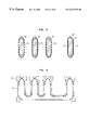
- FIG. 17 shows a line and space pattern as an inspection layout pattern 171 .
- FIG. 18 shows a finished pattern 181 based on the inspection layout pattern 171 of FIG. 17 .
- FIG. 19 shows an error output 191 caused by comparing the finished pattern 181 of FIG. 18 with the inspection layout pattern 171 .
- FIG. 20 shows a reference layout pattern (a design layout pattern before being modified) 201 .
- FIG. 21 shows an error output in case of comparing the finished pattern 181 computed from the inspection layout pattern 171 with the reference layout pattern 201 .
- the reference layout pattern 201 is modified to be the inspection layout pattern 171 so that the errors are not output, then the inspection layout pattern 171 is actually used for a pattern forming apparatus.
- FIG. 22 is a flowchart showing an operation of a pattern distortion detecting apparatus of FIG. 16 .
- a pattern distortion information is output to the pattern distortion information holding section 9 of FIG. 16 .
- the pattern distortion information selecting means 14 performs graphical operation between the design layout pattern or reference layout pattern and the pattern distortion information to output the result as an error information to the error information holding section 15 .
- the errors are selected by performing a logical operation with one of other design layers.
- FIG. 23 shows an example of a design layout pattern.
- reference numeral 231 denotes a gate of a transistor
- 232 denotes an active region.
- FIG. 24 shows, for a comparison, an example of an error output which is produced in inspecting the pattern distortion with the gate lead 231 as an input pattern according to the method of the first embodiment.
- reference numeral 231 denotes a gate of a transistor
- 232 denotes an active region
- 241 denotes a pattern distortion error.
- the dimension of the error 241 on the active region 232 is important in the circuit design in order to define the transistor characteristics, but other parts are not required to have high accuracy in this circuit design. Therefore, it is required to provide a function which selects these errors depending on their circuit design importance.
- FIG. 25 shows an error output example as a result of performing the pattern distortion inspection according to the sixth embodiment.
- reference numeral 232 denotes an active region
- 251 denotes an error output from the pattern distortion information holding section 9 at step 221 (ST 221 ) in FIG. 22 .
- the error selection depending on its circuit design importance is performed such that the pattern distortion information selecting conditions holding section 13 of FIG. 16 outputs the pattern distortion information selecting condition which commands to “perform AND operation between the error and the active region”, to the pattern distortion information selecting means 14 .
- the pattern distortion information selecting means 14 Based on the input condition, the pattern distortion information selecting means 14 performs operation which is “to perform AND operation between an error and an active region” to be able to select only an error presented on the active region.
- FIG. 26 shows the errors which are selected as described above and are output to the error information holding section 15 .
- reference numeral 231 denotes a gate of a transistor
- 232 denotes an active region
- 261 denotes an error selected depending on its importance.
- the pattern distortion detecting method and apparatus can be provided that can select the errors by logical operation on other design layers and the pattern distortion errors.
- a pattern distortion error selecting function for selecting the error importance can be provided. That is, performing the selection of the detected pattern distortion errors enables to detect the important errors with high fidelity.
- pattern distortion information selecting means is provided for performing logical operation between the pattern distortion in the design layout pattern and other design layers.
- selecting of the importance level of the pattern distortion is performed by the logical operation.
- a pattern distortion detecting apparatus of FIG. 16 described in the sixth embodiment is also used.
- FIG. 27 is a flowchart of error selection in the seventh embodiment.
- step 26 a (ST 26 a ) and step 28 a (ST 28 a ) are different from those in the FIG. 2 of the first embodiment, and other parts are the same with FIG. 2 .
- an inspection layout pattern is used in the step 21 (ST 21 )
- a reference layout pattern is used in the step 24 .
- step 25 it is judged whether or not the lower limit test reference pattern data are completely included within the predicted finished pattern at step 25 (ST 25 ), and information of the positions and the sizes of the regions not being included within the predicted finished pattern is output at step 26 (ST 26 ). It is judged whether or not the predicted finished pattern is completely included within the upper limit test reference pattern at step 27 (ST 27 ), and information of the positions and the sizes of such a region not being included within the upper limit test reference pattern is output at step 28 (ST 28 ). The both outputs are sent to the same indication.
- this seventh embodiment it is judged whether or not the lower limit test reference pattern data are completely included within the predicted finished pattern at step 25 (ST 25 ), and information of the positions and the sizes of the regions not being included within the predicted finished pattern is output to a designated indication at step 26 a (ST 26 a ) as an error for shrinking. And it is Gag judged whether or not the predicted finished pattern is completely included with in the upper limit test reference pattern at step 27 (ST 27 ), then information of the positions and the sizes of such a region not being included within the upper limit test reference pattern is output to another indication at step 28 a (ST 28 a ) as an error for expanding. That is, each of the outputs is sent to the individual indication to be independently displayed or colored.
- the errors detected at the step 26 a (ST 26 a ) and at the step 28 a (ST 28 a ) are respectively sent to the different output area. This is remarkably different from the first embodiment.
- FIG. 28 shows a result of inspecting the gate lead pattern 231 of the transistor described in FIG. 23 .
- reference numeral 231 denotes a gate lead of a transistor
- 232 denotes an active region
- 281 denotes an error region distorting the pattern to be shrunk
- 282 denotes an error region distorting the pattern to be expanded. Both errors are found to be individually output by the selecting operation.
- different colors are respectively described in different hatchings.
- each of the pattern distortions which shrinks or expands the pattern is selected to be detected.
- FIG. 29 shows a result of process in which the sixth embodiment is combined with the seventh embodiment.
- the errors in the important positions of this circuit design are selected, and the error 291 which shrinks the pattern is distinguished from the error 292 which expands the pattern.
- a pattern distortion detecting method and apparatus for selecting errors depending on whether the finished pattern shrinks or expands more than the design layout pattern.
- the pattern distortion detecting means selects and detects whether the finished pattern shrinks or expands more than the design layout pattern by comparing the polygonized predicted finished pattern with the test reference pattern.
- positions at which the pattern distortion is large are detected by comparing the predicted finished pattern data with the design layout pattern data (or the reference layout data).
- the design layout pattern data or the reference layout data.
- FIG. 30 shows an example of a design layout pattern 301 .
- FIG. 31 shows a distribution of the optical intensity, resist solubility calculated from the optical intensity or etching rate, relating to the position on the dotted line A—A in FIG. 30.
- a horizontal axis denotes the positions at the dotted line A—A in FIG. 30, and a vertical axis denotes an optical intensity or so on.
- FIG. 32 shows another design layout pattern 321
- FIG. 33 shows a intensity graph for the position on the dotted line B—B in FIG. 32 as the same as FIG. 31 .
- a position corresponding to a certain intensity such as an intensity ‘t’ in FIG. 31 or FIG. 33 is considered to be an edge of the finished pattern, so that the finished pattern is predicted and the portion in which the distortion between this pattern and the design layout pattern is large is detected.
- the results of inspecting the design layout patterns in FIG. 30 and FIG. 32, according to the first embodiment, are respectively shown in FIG. 34 and FIG. 35 .
- reference numeral 301 denotes a design layout pattern and 341 denotes a finished pattern predicted by the above described intensity t.
- reference numeral 321 denotes a design layout pattern and 351 denotes a finished pattern predicted by the above described intensity ‘t’.
- the amount of the gap between the finished pattern and the design layout pattern is not seen, so that the inspection results never show their difference.
- FIG. 36 shows finished patterns, corresponding to the design layout pattern of FIG. 30, when the intensity which defines the pattern edge is changed.
- reference numeral 301 denotes a design layout pattern
- reference numerals 361 , 362 and 363 denote the finished patterns when their pattern edges are respectively decided by the intensities ‘t’, ‘tu’ and ‘tl’.
- FIG. 37 shows finished patterns corresponding to the design layout patterns in FIG. 32 .
- reference numeral 321 denotes a design layout pattern
- reference numerals 371 , 372 and 373 denote the finished patterns when their pattern edges are considered to be respectively decided by the intensities ‘t’, ‘tu’ and ‘tl’.
- FIG. 37 shows that, comparing to FIG. 36, the variations between the sizes of the finished patterns are remarkable depending on the intensities which define the finished patterns. This is because the intensity contrast at the pattern edges in FIG. 37 is lower than that in FIG. 36, as understood by comparing the graph of FIG. 31 and that of FIG. 33 .
- the finished state of the pattern is not good at the position where its contrast is low, it is necessary to inspect such a position.
- the optical intensity distribution itself varies.
- the defocus value for example, among the optical conditions is changed, the optical intensity itself varies. In this case, it is also necessary to inspect the positions where the difference between the pattern variations is large.
- a pattern distortion detection which solves such a problem will be explained.
- FIG. 38 is a block diagram showing the configuration of a pattern distortion detecting apparatus according to the eighth embodiment.
- reference numeral 16 denotes a contrast inspecting conditions holding section for holding conditions which inspect the contrast of the pattern
- 17 denotes a contrast information detecting means for detecting the contrast information of the pattern based on the contrast inspecting conditions
- 18 denotes a contrast information holding section for holding a result of inspection.
- Two or more predicted finished pattern data holding sections 5 are provided in the configuration, and FIG. 38 shows two predicted finished pattern data holding sections as an example.
- the configuration of the eighth embodiment is different from that of the first embodiment. That is, a plurality of predicted finished pattern data holding sections 5 are provided which holds a plurality of predicted finished pattern data being predicted by a plurality of optical conditions or pattern forming process conditions such as a plurality of optical intensities. Further, the contrast information detecting means 17 which receives the contrast inspecting conditions from a contrast inspecting conditions holding section 16 is provided to output the information to the contrast information holding section 18 .
- a contrast inspecting condition for example, a decreasing amount of the pattern which is defined to a certain value, that will be described hereinafter, may be adopted, and this value is held by the contrast information holding section 18 .
- FIG. 39 is a flowchart showing an operation of a pattern distortion detecting apparatus of FIG. 38 .
- step 391 ST 391
- step 392 ST 392
- predicted finished patterns are respectively computed based on each of the optical conditions or each of the pattern forming process conditions, to output the computed results to the predicted finished pattern data holding sections 5 respectively.
- step 393 ST 393
- the contrast information detecting means 17 decides that which one of the output patterns should be subtracted from the other one in the next step, based on the mask tone information or the inclusion relationship between the output patterns.
- step 394 subtraction is performed between the predicted finished patterns.
- step 395 the size of the subtracted pattern is under-sized by a designated amount, corresponding to the inspecting conditions from the contrast inspecting conditions holding section 16 , then the result is output to the contrast information holding section 18 . In this way, a part with low contrast may be detected by under-sizing the subtracted pattern.
- a predicted finished pattern 401 as described in FIG. 40 and a predicted finished pattern 411 as described in FIG. 41 are output at step 391 (ST 391 ) and step 392 (ST 392 ) respectively.
- an optical intensity of the exposure for pattern forming is changed as a plurality of optical conditions or pattern forming process conditions.
- step 393 it is judged that the result of FIG. 41 is subtracted from the result of FIG. 40 .
- FIG. 42 shows a pattern 421 which is a result of subtraction at step 394 (ST 394 ). Further, the subtracted pattern is under-sized in order to detect a position where the contrast is low, and this result is as shown in FIG. 43 . Since the positions with low contrast are not included, the under-sized pattern or error pattern is not output.
- under-sizing means that the outside of the pattern 421 of FIG. 42 (that is, the outside of the pattern 401 of FIG. 40) is shrunk by a certain amount, and the inside of the pattern 421 of FIG. 42 (that is, the outside of the pattern 411 of FIG. 41) is enlarged by a certain amount.
- step 391 predicted finished pattern 441 as described in FIG. 44 and predicted finished pattern 451 as described in FIG. 45 are output at step 391 (ST 391 ) and step 392 (ST 392 ) respectively.
- step 393 step 393
- step 394 step 394
- the resulted pattern of FIG. 45 is subtracted from that of FIG. 44 to obtain a pattern 461 as described in FIG. 46 .
- the subtracted pattern is under-sized, and an error pattern 471 as described in FIG. 47 can be obtained.
- a low contrast position in the predicted finished pattern may be detected where the process condition is poor.
- a pattern distortion detecting method and apparatus in which the predicted finished patterns are obtained corresponding to a plurality of optical conditions or pattern forming process conditions such as a plurality of optical intensities, subtraction between the predicted finished patterns is performed, the resulted pattern is under-sized by a certain amount to detect a position with low contrast, and the contrast is inspected.
- a pattern distortion detecting method and apparatus can further comprise a contrast inspecting function for outputting a pattern distortion error corresponding to a position where the contrast of the optical intensity is lower than a certain level.
- this embodiment can inspect a position where the variations of the predicted finished pattern dimension are remarkable, considering the variations of a plurality of optical conditions or a plurality of pattern forming process conditions.
- a predicted finished layout pattern is formed based on a design layout pattern or a inspection layout pattern.
- An outline of the predicted finished layout pattern is converted into a polygon to generate a polygonized predicted finished layout pattern.
- a pattern distortion in said predicted finished layout pattern is detected by logical figure operation of the input data of said polygonized predicted finished layout patterns.
- the logical figure operation may be a comparison operation between polygonized predicted finished layout patterns.
- a pattern distortion detecting apparatus may be constituted by an electric computer system.
- a process of pattern distortion detecting may be recorded as an computer program in a recording media.
- method of pattern distortion detection may be carried out by a computer by reading out the computer program. This applies to other embodiment to be described below.
- contrast information detecting means is provided for searching a plurality of predicted finished patterns by the finished pattern predicting means based on a plurality of optical conditions and/or a plurality of patterns forming process conditions, and for obtaining contrast information of the predicted finished pattern based on a difference between the plurality of predicted finished patterns.
- the contrast information detecting means performs subtracting operation between the plurality of predicted finished patterns, and under-sizes an obtained figure by a designated amount to detect a low contrast part of the predicted finished pattern.
- FIG. 48 is a combination of FIG. 16 and FIG. 38, and is a block diagram showing an example of configuration of a pattern distortion detecting apparatus including all of the functions explained in the sixth through eighth embodiments.
- a pattern distortion detecting apparatus having all of the functions of the sixth through eighth embodiments can be provided according to the above described explanations.
- a pattern distortion was inspected only by means of a single predicted finished pattern. Accordingly, highly accurate inspection is restricted when there are some differences in optical conditions or process conditions.
- FIG. 49 is a block diagram showing the configuration of a pattern distortion detecting apparatus according to a tenth embodiment of the present invention. Comparing FIG. 49 with FIG. 1, it is noticed that the design layout pattern data holding section 1 in FIG. 1 is separated into a reference layout pattern data holding section 1 a and an inspection layout pattern data holding section 1 b in FIG. 49 . It has been shown, however, for the configuration in FIG. 16 in a sixth embodiment and is not novel for this embodiment.
- the configuration in FIG. 49 is different from the configuration in FIG. 1 in the following points.
- the predicted finished pattern data holding section 5 is connected to a first highly-defined finished pattern detecting means 19 .
- a first finished pattern predicting specification holding section 20 is connected as an input to the first highly-defined finished pattern predicting means 19
- a first highly-defined predicted finished pattern data holding section 21 is connected as an output.
- the reference layout pattern data holding section 1 a is connected as an input to the first highly-defined predicted finished pattern detecting means 19 .
- an output of the first highly-defined prediction finished pattern data holding section 21 is connected to a pattern distortion detecting means 8 .
- the tenth embodiment is characterized in that it comprises the first highly-defined finished pattern predicting means 19 connected to the reference layout pattern data holding section 1 a , the predicted finished pattern data holding section 5 , and the first finished pattern predicting specification holding section 20 as inputs.
- FIG. 50 is a flowchart showing the operation of the pattern distortion detecting apparatus having the above constitution.
- steps 501 (ST 501 ) to 503 (ST 503 ) are similar to steps 21 (ST 21 ) to 23 (ST 23 ) in FIG. 2 in the first embodiment.
- steps 505 (ST 505 ) and later in FIG. 50 are similar to steps 25 (ST 25 ) and later in FIG. 2 .
- Step 504 (ST 504 ) in FIG. 50 is characteristic of this embodiment.
- step 504 (ST 504 ) logical figure operations are performed between a design layout pattern (an original layout pattern) and the predicted layout patterns based on finished pattern predicting specification for refining a predicted finished pattern corresponding to a plurality of optical conditions and/or a plurality of pattern forming process conditions.
- the “finished pattern predicting specification” means a logic to perform logical figure operation between a reference layout pattern and a plurality of predicted finished layout patterns corresponding to a plurality of optical or pattern forming conditions.
- logical figure operation means operation that is carried out by one or combination of operations such as AND, OR, NOT, XOR, sizing, inclusion relation processing among figure patters, contacting, corner portion processing, internal or external distance processing, etc, which can be operated as a general layout inspection tool.
- FIG. 51 shows a concrete example of an input layout pattern, that is, a design layout pattern.
- reference numeral 511 denotes an active area of a transistor and 512 a gate wiring of the transistor.
- 521 denotes the same active area as in FIG. 51
- 522 is a predicted pattern using the gate wiring 512 in FIG. 51 as an input.
- FIG. 53 a shape of a pattern actually formed on a wafer is shown in FIG. 53 .
- 531 denotes the same active area as in FIG. 51
- 532 denotes a shape of a pattern of a gate wiring 512 in FIG. 51 actually formed on a wafer.
- a comparison between FIG. 52 and FIG. 53 shows that the shapes of parts not overlapping the active areas 521 and 531 are quite different.
- An area of the gate wiring 522 is formed following formation of an area of the active area 521 in actual wafer processing. However, there is vertical differences in a normal line direction against a sheet plane between the inside and the outside of the active area 521 in an actual wafer. As a result, a pattern of the gate wiring area 522 formed differs between the inside and the outside of the active area 531 as shown in FIG. 53 . Therefore, a function to change pattern predicting methods is required for parts under different conditions on layout, such as the inside and the outside of the active area 531 .
- FIG. 54 is to explain a concrete example of pattern predicting specification of the tenth embodiment and shows the relationship between the predicted pattern for gate wiring and the active area (active areas 511 , 521 , and 531 in FIGS. 51 - 53 ).
- reference numerals 541 and 542 denote an active area and a predicted pattern for the gate wiring and 542 a shows a predicted pattern for the outside of the region 541 and 542 b is that for the inside.
- the predicted patterns 542 a and 542 b can be obtained by NOT processing and AND processing of the predicted pattern 542 and the active area 541 , respectively.
- the finished pattern predicting specification for graphical operation is set “to under-size the area of the predicted pattern 542 a , and to merge (OR processing) the results and the predicted pattern 542 b ”, which is supplied from the first finished pattern predicting specification holding section 20 to the first highly-defined finished pattern predicting means 19 .
- the predicted pattern 552 as shown in FIG. 55 is obtained.
- the active area 551 in FIG. 55 is the same as that in FIGS. 51-53.
- FIG. 55 shows an example of a predicted finished pattern according to this embodiment.
- a predicted pattern close to the condition in FIG. 53 can be obtained by applying the finished pattern predicting specification to the flow in FIG. 50 .
- polygonized predicted finished pattern can be highly defined by performing logical figure operations between polygonized predicted finished patterns and a design layout pattern based on finished pattern predicting specification corresponding to a plurality of optical conditions and/or a plurality of pattern forming process conditions in the highly-defined finished pattern predicting means 19 .
- finished patterns for the processes under partially different conditions can be predicted and pattern distortion can be inspected according to the prediction.
- this embodiment is effective for deformations of predicted patterns generally correlated to a layout as well as influence of the step portions.
- a refined finished pattern predicting means is provided to highly define the polygonized predicted finished pattern by performing graphical operations between the polygonized predicted finished pattern and the design layout pattern based on finished pattern predicting specification corresponding to a plurality of optical conditions and/or a plurality of pattern forming process conditions.
- FIG. 56 is a block diagram showing the configuration of the pattern distortion detecting apparatus according to an eleventh embodiment of the present invention.
- FIG. 56 there is provided multiple sets of the configuration from the finished patterns predicting means 2 to 4 the predicted finished pattern data holding section 5 , that is, the finished pattern predicting means 2 , the predicted finished pattern outlines polygonizing means 3 , the number-of-apices reducing means 4 , the predicted finished pattern data holding section 5 , in FIG. 49 .
- FIG. 56 two sets are shown.
- a second highly-defined finished pattern predicting means 22 is provided, to which a plurality of predicted finished pattern data holding section 5 are connected as a plurality of inputs.
- a second finished pattern predicting specification holding section 23 is connected as an input, and a second highly-defined predicted finished pattern data holding section 24 is connected as an output.
- the output of the second highly-defined predicted finished pattern data holding section 24 is connected to the pattern distortion detecting means 8 .
- the reference layout pattern data holding section 1 a is connected as an input.
- the eleventh embodiment is characterized in that the second highly-defined finished pattern predicting means 22 , to which the reference layout pattern data holding section 1 a and a plurality of predicted finished pattern data holding section 5 and the second finished pattern predicting specification holding sections 23 are input, as mentioned above.
- FIG. 57 is a flowchart showing the operation of pattern distortion detection according to this embodiment. Steps 571 (ST 571 ) to 573 (ST 573 ) inthe flowchart shown in FIG. 57 are similar to steps 501 (ST 501 ) to 503 (ST 503 ) in FIG. 50 of the tenth embodiment. In addition, steps 576 (ST 576 ) or later in FIG. 57 are also similar to steps 505 (ST 505 ) or later in FIG. 50 .
- Steps 574 (ST 574 ) and 575 (ST 575 ) in FIG. 57 are characteristic of this embodiment.
- a predicted finished pattern is obtained under one condition in FIG. 50 for the tenth embodiment, whereas a flow from step 571 (ST 571 ) to step 573 (ST 573 ) is repeated several times under a plurality of conditions, that is, corresponding to a plurality of optical conditions and/or pattern formation process conditions, in step 574 (ST 574 ) in the flow of this embodiment.
- a predicted finished pattern can be obtained by performing graphical operations on a plurality of finished patterns thus obtained, based on the second finished pattern specification based on the second finished pattern predicting specification supplied by the second finished pattern predicting specification holding section 23 in the second highly-defined finished pattern predicting means 22 in step 575 (ST 575 ).
- FIG. 58 is to explain a process of pattern prediction according to this embodiment.
- a gate wiring 512 in FIG. 51 is to be inspected, optical or process conditions differ between the inside and the outside of the active area 511 , as mentioned above.
- FIG. 58 shows an example of pattern prediction performed under different conditions.
- the active area 581 in FIG. 58 is the same as the active area 511 in FIG. 51 .
- Reference numeral 582 in FIG. 58 is a pattern predicted under the conditions for the outside of the active area 581
- 583 is a pattern predicted under the conditions for the inside of the active area 591 .
- a highly-defined predicted finished pattern is generated by predicting a plurality of finished predicted patterns corresponding to a plurality of processes with partially different optical condition and/or pattern forming process conditions, performing graphical operations between the predicted patterns and a design layout pattern, and merging the results.
- This highly-defined predicted finished pattern thus obtained can be employed to perform inspection of pattern distortion more accurately than in the tenth embodiment. It is apparent that this embodiment is effective not only for influence of the step height but also for deformations of a predicted pattern generally correlated to a layout.
- a highly-defined finished pattern predicting means is provided to generate a highly-defined predicted finished pattern by performing graphical operations between each of a plurality of polygonized predicted finished patterns generated corresponding to a plurality of optical conditions and/or a plurality of pattern forming process conditions and the design layout patterns based on preset finished pattern predicting specification and merging the results.
- a pattern distortion inspecting apparatus and an inspection flow in a twelfth embodiment are explained by means of the same figure as for the first embodiment. (The configuration of the pattern distortion inspecting apparatus and the inspection flow in the twelfth embodiment are the same as those in the eleventh embodiment.)
- graphical operations are conducted between each of a plurality of predicted finished patterns and a design layout pattern.
- graphical operations are performed among a plurality of predicted finished patterns.
- FIG. 59 shows an input layout pattern, that is, a layout pattern to be subjected to inspection.
- FIGS. 60-62 show predicted finished patterns predicted under different conditions.
- FIG. 63 is provided to explain a concrete example of pattern predicting specification according to this embodiment, in which FIGS. 60-62 are overlapped.
- the smallest pattern can be obtained by AND processing of all predicted finished patterns (predicted pattern 633 in FIG. 63) and the largest pattern by OR processing of all predicted finished patterns (predicted pattern 632 in FIG. 63 ).
- FIG. 64 more accurate prediction can be achieved by using a predicted finished pattern 641 in FIG. 64 of the active area 581 in place of the active area 581 in FIG. 58 of the eleventh embodiment and performing graphical operations between the predicted finished patterns and the predicted patterns 642 and 643 .
- FIG. 64 is provided to illustrate a concrete example of pattern predicting specification according to this embodiment.
- a highly-defined finished pattern predicting means is provided to perform graphical operations among a plurality of polygonized predicted finished patterns generated corresponding to a plurality of optical conditions and/or a plurality of pattern forming process conditions and outputting the results as a predicted finished pattern.
- regions of the predicted finished patterns where there is a pattern distortion from the design layout pattern larger than the allowable range are detected by predicting the finished patterns from the design layout pattern and performing logical figure operations between the predicted finished patterns and the design layout pattern (See FIG. 1 ).
- regions of the predicted finished patterns where there is a pattern distortion from the reference layout pattern larger than the allowable range are detected by predicting the finished predicted patterns based on the inspection layout pattern and performing logical figure operations between the finished predicted patterns and the reference layout pattern (See FIG. 16 ).
- the fourteenth embodiment described hereinafter is performed to improve the above situation.
- This embodiment is intended to inspect differences among the respective results obtained under various conditions by performing graphical operations on a plurality of finished predicted patterns generated under the various conditions to detect regions that are different among a plurality of the finished predicted patterns.
- FIG. 65 is a block diagram showing the configuration of the pattern distortion detecting apparatus according to the fourteenth embodiment.
- the inspection layout pattern data holding section 1 b the pattern forming process conditions holding section 10 , the finished pattern predicting means 2 , the predicted finished pattern outlines polygonizing means 3 , the number-of-apices reducing means 4 , and the predicted finished pattern data holding section 5 in FIG. 65 are similar to those in FIG. 16, there are provide two sets in FIG. 65 .
- a predicted finished pattern comparing means 25 is newly connected to a plurality of predicted finished pattern data holding sections 5 .
- a predicted pattern data comparing specification holding section 26 is also connected as an input and a finished pattern difference information holding section 27 is connected as an output.
- the fourteenth embodiment is characterized in that the predicted finished pattern comparing means 25 is incorporated, which is connected to a plurality of predicted finished pattern data holding sections 5 and the predicted finished pattern data comparing specification holding section 26 as its inputs.
- FIG. 66 is a flowchart showing the operation of the pattern distortion detecting apparatus having the above configuration. Steps 661 to 663 (ST 661 to ST 663 ) and steps 661 ′ to 663 ′ (ST 661 ′ jto ST 663 ′) in FIG. 66 are the same as steps 21 to 23 (ST 21 to ST 23 ) in FIG. 2 . However, “the design layout pattern” for the step 21 in FIG. 2 should be read as “inspection layout pattern” in FIG. 66 .
- the steps 661 to 663 differ from the steps 661 ′ to 663 ′ (ST 661 ′ to ST 663 ′) only in the inspection layout pattern data or/and pattern forming process conditions respectively employed.
- step 664 graphical operations are performed among a plurality of predicted finished pattern data based on the predicted finished pattern comparing specification supplied from the predicted finished pattern data comparing specification holding section 26 , and the results are output as the predicted finished pattern difference information and stored in the predicted finished pattern difference information holding section 27 .
- the fourteenth embodiment is characterized in that it comprises a plurality of sets of the operation in the steps 661 to 663 (ST 661 to ST 663 ) and that it also comprises the step 664 (ST 664 ) to detect differences by performing graphical operations among a plurality of predicted finished patterns thus obtained.
- a specific predicted finished pattern is selected, as one aspect for comparison among a plurality of predicted finished patterns, from a plurality of predicted finished patterns, and a test reference pattern is generated based on the selected pattern.
- the test reference pattern is compared with a plurality of predicted finished patterns, or graphical operations are performed among a plurality of predicted finished pattern data.
- test reference patterns a upper limit test reference pattern to define the allowable upper limit larger than the specific predicted finished pattern and a lower limit test reference pattern to define the allowable lower limit smaller than the specific predicted finished pattern are generated. Then, the upper and lower test reference patterns are compared with a plurality of predicted finished patterns by NOT processing.
- regions that are different among a plurality of predicted finished patterns can be detected. It is also apparent that different regions thus detected can be classified as described below.
- regions that are different among the predicted pattern data can be detected by predicting a plurality of finished patterns corresponding to a plurality of different pattern forming process conditions and/or a plurality of inspection layout pattern data and performing graphical operations on a plurality of predicted finished pattern data thus predicted.
- each of the above-described pattern distortion detecting apparatus and method of the present invention is effectively used for manufacture of a semiconductor device.
- a semiconductor manufacturing process many patterns are formed by a photolithography technique or the like and there are many pattern forming processes such as an etching process.
- the pattern distortion detecting apparatus and method of the invention can be used to accurately form ultra-fine patterns in those many pattern forming processes. Further, such a manufacturing process can produce a semiconductor device in which fine patterns with few distortions are formed.
- the pattern distortion detecting apparatus and method of the present invention can detect a pattern distortion with high accuracy by comparing highly accurately predicted finished pattern data that are calculated by using an optical intensity simulation or the like with test reference pattern data that are generated from design layout pattern data.
- a pattern distortion can be detected by directly comparing predicted finished pattern data with design layout pattern data.
- a pattern distortion can be detected with high accuracy in connection with the pattern line width.
- a general-purpose design rule check program can be used for the generation of test reference patterns and the comparison between the test reference patterns and predicted patterns.
- pattern distortion detecting apparatus and method of the present invention since pattern distortion upper limit test reference patterns and pattern distortion lower limit test reference patterns are formed separately, a pattern distortion can be detected with high accuracy by separately setting an allowable upper limit value and an allowable lower limit value.
- test reference patterns are deformed so as not to detect a pattern distortion at pattern corner portions. Therefore, only a pattern distortion relating to a pattern line width that is required to be highly accurate can be detected with high accuracy.
- test reference patterns are generated merely by generating rectangles at the corners, performing graphical operations on the rectangles and design layout patterns, and then executing a sizing process. Therefore, a general-purpose design rule check program can also be used for this purpose. Thus, the system can be constructed simply and easily.
- the pattern distortion detecting apparatus and method of the present invention since the size of rectangles generated at corner portions of a design layout pattern is adjusted in forming a test reference pattern, a pattern distortion of shorter sidelines of a pattern can also be detected with high accuracy.
- rectangular regions smaller than rectangular regions to be set at corner portions of a sideline are set at both corner portions of a minute step portion of a pattern in forming a test reference pattern. Therefore, also a pattern distortion at or in the vicinity of a minute step portion can be detected with high accuracy.
- a rectangular region smaller than rectangular regions to be set at corner portions of a sideline is set at a certain position between both corner portions of a minute step portion of a pattern in forming a test reference pattern. Therefore, also a pattern distortion at or in the vicinity of a minute step portion can be detected with high accuracy.
- the pattern distortion can be calculated precisely by directly comparing design layout pattern data with predicted finished pattern data. A distortion amount of this portion can be reported precisely. Further, the design layout pattern data can be corrected precisely based on the reported distortion amount.
- the pattern distortion detecting process can judge whether the predicted pattern is shrunk or enlarged more than the design layout pattern, and the results are selected and detected. Therefore, it is possible to correct the design layout pattern data precisely.
- the design layout pattern data can be precisely corrected.
- the above described pattern distortions can be selected depending on their importance by the above described logical operation. Therefore, it is possible to correct the design layout pattern data precisely.
- the design layout pattern data can be precisely corrected.
- the pattern distortion detecting apparatus and method of the present invention it is possible to perform subtracting operation between a plurality of predicted finished patterns, and further to under-size the resulted pattern in order to detect a position with low contrast in the predicted finished pattern. Therefore, -the design layout pattern data can be precisely corrected.
- a predicted finished pattern can be highly defined corresponding to process conditions, since graphical operations are performed between polygonized predicted finished patterns and a design layout pattern based on finished pattern predicting specification corresponding to a plurality of process conditions.
- a predicted finished pattern can be highly defined corresponding to process conditions, since a plurality of polygonized predicted finished patterns are generated corresponding to a plurality of process conditions and graphical operations are performed between the polygonized predicted finished patterns and a design layout pattern.
- a predicted finished pattern can be highly defined corresponding to process conditions, since a plurality of polygonized predicted finished patterns are generated corresponding to a plurality of process conditions and graphical operations are performed among a plurality of the predicted finished patterns.
- regions that are different among the predicted finished pattern can be detected by predicting a plurality of finished patterns corresponding to a plurality of pattern forming process conditions and/or a plurality of inspection layout pattern and performing graphical operations on a plurality of predicted finished pattern thus predicted in a manufacturing process for semiconductors.
- the pattern distortion detecting apparatus and the detecting method of the present invention it is possible to inspect differences among the respective finished predicted patterns obtained under various conditions by performing graphical operations on a plurality of finished predicted patterns generated under the various conditions.
Abstract
Description
Claims (20)
Applications Claiming Priority (8)
| Application Number | Priority Date | Filing Date | Title |
|---|---|---|---|
| JP33571197 | 1997-12-05 | ||
| JP9-335711 | 1997-12-05 | ||
| JP21152298 | 1998-07-27 | ||
| JP10-211522 | 1998-07-27 | ||
| JP10-287975 | 1998-10-09 | ||
| JP28797598 | 1998-10-09 | ||
| JP33771098A JP4076644B2 (en) | 1997-12-05 | 1998-11-27 | Pattern distortion detection apparatus and detection method |
| JP10-337710 | 1998-11-27 |
Publications (1)
| Publication Number | Publication Date |
|---|---|
| US6343370B1 true US6343370B1 (en) | 2002-01-29 |
Family
ID=27476551
Family Applications (1)
| Application Number | Title | Priority Date | Filing Date |
|---|---|---|---|
| US09/203,582 Expired - Lifetime US6343370B1 (en) | 1997-12-05 | 1998-12-02 | Apparatus and process for pattern distortion detection for semiconductor process and semiconductor device manufactured by use of the apparatus or process |
Country Status (3)
| Country | Link |
|---|---|
| US (1) | US6343370B1 (en) |
| JP (1) | JP4076644B2 (en) |
| KR (1) | KR100300652B1 (en) |
Cited By (26)
| Publication number | Priority date | Publication date | Assignee | Title |
|---|---|---|---|---|
| US20020111784A1 (en) * | 2001-02-12 | 2002-08-15 | Keller S. Brandon | Method of suggesting configuration commands based on E-CAD tool output |
| US20020138813A1 (en) * | 2001-03-20 | 2002-09-26 | Cheehoe Teh | System & method for performing design rule check |
| US6507931B2 (en) * | 2000-06-30 | 2003-01-14 | Kabushiki Kaisha Toshiba | Semiconductor integrated circuit designing method and system |
| US20030168596A1 (en) * | 1999-10-07 | 2003-09-11 | Hitachi, Ltd. | Microstructured pattern inspection method |
| US6658641B2 (en) * | 2000-10-18 | 2003-12-02 | Isao Ashida | Method for mask data verification and computer readable record medium recording the verification program |
| US20030229479A1 (en) * | 2002-06-07 | 2003-12-11 | Smith Taber H. | Dummy fill for integrated circuits |
| US20030229410A1 (en) * | 2002-06-07 | 2003-12-11 | Smith Taber H. | Integrated circuit metrology |
| US20030228714A1 (en) * | 2002-06-07 | 2003-12-11 | Smith Taber H. | Dummy fill for integrated circuits |
| US20030226757A1 (en) * | 2002-06-07 | 2003-12-11 | Smith Taber H. | Dummy fill for integrated circuits |
| US20040031005A1 (en) * | 2002-03-08 | 2004-02-12 | Umc Japan | Electronic cad system and layout data producing method therefor |
| US20040058255A1 (en) * | 2002-09-24 | 2004-03-25 | Scott Jessen | Substrate topography compensation at mask design: 3D OPC topography anchored |
| US6854093B1 (en) * | 2000-11-15 | 2005-02-08 | Reshape, Inc. | Facilitating press operation in abutted-pin hierarchical physical design |
| US20050076323A1 (en) * | 2003-10-03 | 2005-04-07 | Taiwan Semiconductor Manufacturing Co., Ltd. | Method for improving the critical dimension uniformity of patterned features on wafers |
| US20050081180A1 (en) * | 2003-08-20 | 2005-04-14 | Toshiya Kotani | Pattern dimension correction method and verification method using OPC, mask and semiconductor device fabricated by using the correction method, and system and software product for executing the correction method |
| US20050132306A1 (en) * | 2002-06-07 | 2005-06-16 | Praesagus, Inc., A Massachusetts Corporation | Characterization and reduction of variation for integrated circuits |
| US20050235246A1 (en) * | 2002-06-07 | 2005-10-20 | Praesagus, Inc., A Massachusetts Corporation | Use of models in integrated circuit fabrication |
| US20060075366A1 (en) * | 2004-09-30 | 2006-04-06 | Seongtae Jeong | Test structures for feature fidelity improvement |
| US20070157139A1 (en) * | 2002-06-07 | 2007-07-05 | David White | Characterization and verification for integrated circuit designs |
| US20070256039A1 (en) * | 2002-06-07 | 2007-11-01 | Cadence Design Systems, Inc. | Dummy fill for integrated circuits |
| US20080027698A1 (en) * | 2002-06-07 | 2008-01-31 | Cadence Design Systems, Inc. | Method and System for Handling Process Related Variations for Integrated Circuits Based Upon Reflections |
| US20080052661A1 (en) * | 2006-08-23 | 2008-02-28 | Jae-Hyun Kang | Optical proximity correction (opc) processing method for preventing the occurrence of off-grid |
| US20080281541A1 (en) * | 2001-10-19 | 2008-11-13 | Singh Adit D | System and method for estimating reliability of components for testing and quality optimization |
| US8464192B2 (en) | 2011-01-27 | 2013-06-11 | Renesas Electronics Corporation | Lithography verification apparatus and lithography simulation program |
| US8930857B2 (en) | 2011-06-10 | 2015-01-06 | Renesas Electronics Corporation | Mask data verification apparatus, design layout verification apparatus, method thereof, and computer program thereof |
| US20150089458A1 (en) * | 2013-09-26 | 2015-03-26 | Taiwan Semiconductor Manufacturing Company, Ltd. | Systems and methods for mitigating print-out defects |
| US9697317B1 (en) | 2004-04-21 | 2017-07-04 | Iym Technologies Llc | Integrated circuits having in-situ constraints |
Families Citing this family (11)
| Publication number | Priority date | Publication date | Assignee | Title |
|---|---|---|---|---|
| JP2011081388A (en) * | 1997-12-05 | 2011-04-21 | Renesas Electronics Corp | Apparatus and process for pattern distortion detection |
| JP2001350250A (en) * | 2000-06-05 | 2001-12-21 | Mitsubishi Electric Corp | Pattern distortion correcting device, pattern distortion correcting method and recording medium recorded with pattern distortion correcting program |
| JP4068541B2 (en) | 2003-09-25 | 2008-03-26 | 株式会社東芝 | Integrated circuit pattern verification apparatus and verification method |
| JP2005309140A (en) | 2004-04-22 | 2005-11-04 | Toshiba Corp | Method for manufacturing photomask, method for determining position of photomask defect correction, and apparatus for determining position of photomask defect correction |
| JP2006091576A (en) * | 2004-09-24 | 2006-04-06 | Fujitsu Ltd | Light intensity difference evaluating method and semiconductor device |
| US8112724B2 (en) | 2007-03-20 | 2012-02-07 | Sony Corporation | Method of designing semiconductor integrated circuit, apparatus for designing semiconductor integrated circuit, recording medium, and mask manufacturing method |
| JP4693869B2 (en) * | 2008-06-02 | 2011-06-01 | 株式会社東芝 | Pattern verification method, pattern verification system, mask manufacturing method, semiconductor device manufacturing method |
| JP5514754B2 (en) * | 2011-02-18 | 2014-06-04 | 株式会社ニューフレアテクノロジー | Inspection apparatus and inspection method |
| KR101659309B1 (en) * | 2011-03-24 | 2016-09-26 | 한화테크윈 주식회사 | Vision inspection apparatus and method using the same |
| US8669523B2 (en) * | 2011-05-25 | 2014-03-11 | Kla-Tencor Corporation | Contour-based defect detection using an inspection apparatus |
| JP2021166271A (en) * | 2020-04-08 | 2021-10-14 | 日本コントロールシステム株式会社 | Mask information adjustment device, mask data adjustment method, program |
Citations (13)
| Publication number | Priority date | Publication date | Assignee | Title |
|---|---|---|---|---|
| JPS60201630A (en) | 1984-03-23 | 1985-10-12 | インタ−ナショナル ビジネス マシ−ンズ コ−ポレ−ション | Method of forming inspecting pattern |
| US5530372A (en) * | 1994-04-15 | 1996-06-25 | Schlumberger Technologies, Inc. | Method of probing a net of an IC at an optimal probe-point |
| US5553274A (en) * | 1995-04-17 | 1996-09-03 | International Business Machines Corporation | Vertex minimization in a smart optical proximity correction system |
| JPH08334888A (en) | 1995-06-07 | 1996-12-17 | Hitachi Ltd | Device or inspecting mask pattern data and device for optimumly designing mask pattern data |
| US5663893A (en) * | 1995-05-03 | 1997-09-02 | Microunity Systems Engineering, Inc. | Method for generating proximity correction features for a lithographic mask pattern |
| US5795688A (en) * | 1996-08-14 | 1998-08-18 | Micron Technology, Inc. | Process for detecting defects in photomasks through aerial image comparisons |
| US5801954A (en) * | 1996-04-24 | 1998-09-01 | Micron Technology, Inc. | Process for designing and checking a mask layout |
| US5862058A (en) * | 1996-05-16 | 1999-01-19 | International Business Machines Corporation | Optical proximity correction method and system |
| US5879844A (en) * | 1995-12-22 | 1999-03-09 | Kabushiki Kaisha Toshiba | Optical proximity correction method |
| US5920487A (en) * | 1997-03-03 | 1999-07-06 | Motorola Inc. | Two dimensional lithographic proximity correction using DRC shape functions |
| US6078738A (en) * | 1997-05-08 | 2000-06-20 | Lsi Logic Corporation | Comparing aerial image to SEM of photoresist or substrate pattern for masking process characterization |
| US6081658A (en) * | 1997-12-31 | 2000-06-27 | Avant! Corporation | Proximity correction system for wafer lithography |
| US6154714A (en) * | 1997-11-17 | 2000-11-28 | Heuristic Physics Laboratories | Method for using wafer navigation to reduce testing times of integrated circuit wafers |
-
1998
- 1998-11-27 JP JP33771098A patent/JP4076644B2/en not_active Expired - Fee Related
- 1998-12-02 US US09/203,582 patent/US6343370B1/en not_active Expired - Lifetime
- 1998-12-04 KR KR1019980053147A patent/KR100300652B1/en not_active IP Right Cessation
Patent Citations (14)
| Publication number | Priority date | Publication date | Assignee | Title |
|---|---|---|---|---|
| JPS60201630A (en) | 1984-03-23 | 1985-10-12 | インタ−ナショナル ビジネス マシ−ンズ コ−ポレ−ション | Method of forming inspecting pattern |
| US4581537A (en) | 1984-03-23 | 1986-04-08 | International Business Machines Corporation | Method for generating inspection patterns |
| US5530372A (en) * | 1994-04-15 | 1996-06-25 | Schlumberger Technologies, Inc. | Method of probing a net of an IC at an optimal probe-point |
| US5553274A (en) * | 1995-04-17 | 1996-09-03 | International Business Machines Corporation | Vertex minimization in a smart optical proximity correction system |
| US5663893A (en) * | 1995-05-03 | 1997-09-02 | Microunity Systems Engineering, Inc. | Method for generating proximity correction features for a lithographic mask pattern |
| JPH08334888A (en) | 1995-06-07 | 1996-12-17 | Hitachi Ltd | Device or inspecting mask pattern data and device for optimumly designing mask pattern data |
| US5879844A (en) * | 1995-12-22 | 1999-03-09 | Kabushiki Kaisha Toshiba | Optical proximity correction method |
| US5801954A (en) * | 1996-04-24 | 1998-09-01 | Micron Technology, Inc. | Process for designing and checking a mask layout |
| US5862058A (en) * | 1996-05-16 | 1999-01-19 | International Business Machines Corporation | Optical proximity correction method and system |
| US5795688A (en) * | 1996-08-14 | 1998-08-18 | Micron Technology, Inc. | Process for detecting defects in photomasks through aerial image comparisons |
| US5920487A (en) * | 1997-03-03 | 1999-07-06 | Motorola Inc. | Two dimensional lithographic proximity correction using DRC shape functions |
| US6078738A (en) * | 1997-05-08 | 2000-06-20 | Lsi Logic Corporation | Comparing aerial image to SEM of photoresist or substrate pattern for masking process characterization |
| US6154714A (en) * | 1997-11-17 | 2000-11-28 | Heuristic Physics Laboratories | Method for using wafer navigation to reduce testing times of integrated circuit wafers |
| US6081658A (en) * | 1997-12-31 | 2000-06-27 | Avant! Corporation | Proximity correction system for wafer lithography |
Non-Patent Citations (3)
| Title |
|---|
| "Automated Determination of CAD Layout Failures Through Focus: Experiment and Simulation", by Chris Spence, et al., SPIE vol. 2197, 1994, pp. 302-313. |
| "Fast Chip Level OPC Method on Mask Database", by Hidetoshi Ohnuma, et al., SPIE vol. 3096, 1997, pp. 145-153. |
| "Simple Method of Correcting Optical Proximity for 0.35um Logic LSI Circuits", by Eiichi Kawamura, et al., Japanese Journal of Applied Physics, vol. 34, Dec. 1995, pp. 6547-6551. |
Cited By (82)
| Publication number | Priority date | Publication date | Assignee | Title |
|---|---|---|---|---|
| US7791021B2 (en) | 1999-10-07 | 2010-09-07 | Hitachi, Ltd. | Microstructured pattern inspection method |
| US6765204B2 (en) * | 1999-10-07 | 2004-07-20 | Hitachi, Ltd. | Microstructured pattern inspection method |
| US7217923B2 (en) | 1999-10-07 | 2007-05-15 | Hitachi, Ltd. | Microstructured pattern inspection method |
| US20030168596A1 (en) * | 1999-10-07 | 2003-09-11 | Hitachi, Ltd. | Microstructured pattern inspection method |
| US20070290697A1 (en) * | 1999-10-07 | 2007-12-20 | Fumihiro Sasajima | Microstructured pattern inspection method |
| US8304724B2 (en) | 1999-10-07 | 2012-11-06 | Hitachi, Ltd. | Microstructured pattern inspection method |
| US7435959B2 (en) | 1999-10-07 | 2008-10-14 | Hitachi, Ltd. | Microstructured pattern inspection method |
| US20100314541A1 (en) * | 1999-10-07 | 2010-12-16 | Hitachi, Ltd. | Microstructured pattern inspection method |
| US20050277029A1 (en) * | 1999-10-07 | 2005-12-15 | Fumihiro Sasajima | Microstructured pattern inspection method |
| US20090020699A1 (en) * | 1999-10-07 | 2009-01-22 | Fumihiro Sasajima | Microstructured pattern inspection method |
| USRE42294E1 (en) | 2000-06-30 | 2011-04-12 | Kabushiki Kaisha Toshiba | Semiconductor integrated circuit designing method and system using a design rule modification |
| USRE42302E1 (en) * | 2000-06-30 | 2011-04-19 | Kabushiki Kaisha Toshiba | Method for making a design layout and mask |
| US6507931B2 (en) * | 2000-06-30 | 2003-01-14 | Kabushiki Kaisha Toshiba | Semiconductor integrated circuit designing method and system |
| USRE43659E1 (en) * | 2000-06-30 | 2012-09-11 | Kabushiki Kaisha Toshiba | Method for making a design layout of a semiconductor integrated circuit |
| US6658641B2 (en) * | 2000-10-18 | 2003-12-02 | Isao Ashida | Method for mask data verification and computer readable record medium recording the verification program |
| US6854093B1 (en) * | 2000-11-15 | 2005-02-08 | Reshape, Inc. | Facilitating press operation in abutted-pin hierarchical physical design |
| US20020111784A1 (en) * | 2001-02-12 | 2002-08-15 | Keller S. Brandon | Method of suggesting configuration commands based on E-CAD tool output |
| US6816997B2 (en) | 2001-03-20 | 2004-11-09 | Cheehoe Teh | System and method for performing design rule check |
| US20020138813A1 (en) * | 2001-03-20 | 2002-09-26 | Cheehoe Teh | System & method for performing design rule check |
| US20050086619A1 (en) * | 2001-03-20 | 2005-04-21 | Cheehoe Teh | System & method for performing design rule check |
| US7552408B2 (en) | 2001-03-20 | 2009-06-23 | United Microelectronics Corporation | Method for performing design rule check on mask pattern data for an integrated circuit |
| US20080281541A1 (en) * | 2001-10-19 | 2008-11-13 | Singh Adit D | System and method for estimating reliability of components for testing and quality optimization |
| US20040031005A1 (en) * | 2002-03-08 | 2004-02-12 | Umc Japan | Electronic cad system and layout data producing method therefor |
| US20070256039A1 (en) * | 2002-06-07 | 2007-11-01 | Cadence Design Systems, Inc. | Dummy fill for integrated circuits |
| US7383521B2 (en) | 2002-06-07 | 2008-06-03 | Cadence Design Systems, Inc. | Characterization and reduction of variation for integrated circuits |
| US20050132306A1 (en) * | 2002-06-07 | 2005-06-16 | Praesagus, Inc., A Massachusetts Corporation | Characterization and reduction of variation for integrated circuits |
| US20050196964A1 (en) * | 2002-06-07 | 2005-09-08 | Praesagus, Inc. | Dummy fill for integrated circuits |
| US20050235246A1 (en) * | 2002-06-07 | 2005-10-20 | Praesagus, Inc., A Massachusetts Corporation | Use of models in integrated circuit fabrication |
| US20030229479A1 (en) * | 2002-06-07 | 2003-12-11 | Smith Taber H. | Dummy fill for integrated circuits |
| US20030229410A1 (en) * | 2002-06-07 | 2003-12-11 | Smith Taber H. | Integrated circuit metrology |
| US7124386B2 (en) | 2002-06-07 | 2006-10-17 | Praesagus, Inc. | Dummy fill for integrated circuits |
| US7152215B2 (en) | 2002-06-07 | 2006-12-19 | Praesagus, Inc. | Dummy fill for integrated circuits |
| US7174520B2 (en) | 2002-06-07 | 2007-02-06 | Praesagus, Inc. | Characterization and verification for integrated circuit designs |
| US8001516B2 (en) | 2002-06-07 | 2011-08-16 | Cadence Design Systems, Inc. | Characterization and reduction of variation for integrated circuits |
| US20070101305A1 (en) * | 2002-06-07 | 2007-05-03 | Praesagus, Inc. | Methods and systems for implementing dummy fill for integrated circuits |
| US7962867B2 (en) | 2002-06-07 | 2011-06-14 | Cadence Design Systems, Inc. | Electronic design for integrated circuits based on process related variations |
| US20030229880A1 (en) * | 2002-06-07 | 2003-12-11 | David White | Test masks for lithographic and etch processes |
| US20070157139A1 (en) * | 2002-06-07 | 2007-07-05 | David White | Characterization and verification for integrated circuit designs |
| US7243316B2 (en) | 2002-06-07 | 2007-07-10 | Praesagus, Inc. | Test masks for lithographic and etch processes |
| US20030229881A1 (en) * | 2002-06-07 | 2003-12-11 | David White | Adjustment of masks for integrated circuit fabrication |
| US20050051809A1 (en) * | 2002-06-07 | 2005-03-10 | Praesagus, Inc., A Massachusetts Corporation | Dummy fill for integrated circuits |
| US20050037522A1 (en) * | 2002-06-07 | 2005-02-17 | Praesagus Inc., A Massachusetts Corporation | Dummy fill for integrated circuits |
| US7325206B2 (en) * | 2002-06-07 | 2008-01-29 | Cadence Design Systems, Inc. | Electronic design for integrated circuits based process related variations |
| US20080027698A1 (en) * | 2002-06-07 | 2008-01-31 | Cadence Design Systems, Inc. | Method and System for Handling Process Related Variations for Integrated Circuits Based Upon Reflections |
| US20030228714A1 (en) * | 2002-06-07 | 2003-12-11 | Smith Taber H. | Dummy fill for integrated circuits |
| US7353475B2 (en) * | 2002-06-07 | 2008-04-01 | Cadence Design Systems, Inc. | Electronic design for integrated circuits based on process related variations |
| US7356783B2 (en) | 2002-06-07 | 2008-04-08 | Cadence Design Systems, Inc. | Dummy fill for integrated circuits |
| US7360179B2 (en) | 2002-06-07 | 2008-04-15 | Cadence Design Systems, Inc. | Use of models in integrated circuit fabrication |
| US7363099B2 (en) | 2002-06-07 | 2008-04-22 | Cadence Design Systems, Inc. | Integrated circuit metrology |
| US7363598B2 (en) | 2002-06-07 | 2008-04-22 | Cadence Design Systems, Inc. | Dummy fill for integrated circuits |
| US7367008B2 (en) | 2002-06-07 | 2008-04-29 | Cadence Design Systems, Inc. | Adjustment of masks for integrated circuit fabrication |
| US7380220B2 (en) | 2002-06-07 | 2008-05-27 | Cadence Design Systems, Inc. | Dummy fill for integrated circuits |
| US7853904B2 (en) | 2002-06-07 | 2010-12-14 | Cadence Design Systems, Inc. | Method and system for handling process related variations for integrated circuits based upon reflections |
| US7393755B2 (en) | 2002-06-07 | 2008-07-01 | Cadence Design Systems, Inc. | Dummy fill for integrated circuits |
| US20080216027A1 (en) * | 2002-06-07 | 2008-09-04 | Cadence Design Systems, Inc. | Electronic Design for Integrated Circuits Based on Process Related Variations |
| US20030229412A1 (en) * | 2002-06-07 | 2003-12-11 | David White | Electronic design for integrated circuits based on process related variations |
| US20030237064A1 (en) * | 2002-06-07 | 2003-12-25 | David White | Characterization and verification for integrated circuit designs |
| US20030226757A1 (en) * | 2002-06-07 | 2003-12-11 | Smith Taber H. | Dummy fill for integrated circuits |
| US20090031261A1 (en) * | 2002-06-07 | 2009-01-29 | Cadence Design Systems, Inc. | Characterization and reduction of variation for integrated circuits |
| US20030229868A1 (en) * | 2002-06-07 | 2003-12-11 | David White | Electronic design for integrated circuits based process related variations |
| US7774726B2 (en) | 2002-06-07 | 2010-08-10 | Cadence Design Systems, Inc. | Dummy fill for integrated circuits |
| US7712056B2 (en) | 2002-06-07 | 2010-05-04 | Cadence Design Systems, Inc. | Characterization and verification for integrated circuit designs |
| US7757195B2 (en) | 2002-06-07 | 2010-07-13 | Cadence Design Systems, Inc. | Methods and systems for implementing dummy fill for integrated circuits |
| US20040058255A1 (en) * | 2002-09-24 | 2004-03-25 | Scott Jessen | Substrate topography compensation at mask design: 3D OPC topography anchored |
| US6893800B2 (en) | 2002-09-24 | 2005-05-17 | Agere Systems, Inc. | Substrate topography compensation at mask design: 3D OPC topography anchored |
| US7213226B2 (en) | 2003-08-20 | 2007-05-01 | Kabushiki Kaisha Toshiba | Pattern dimension correction method and verification method using OPC, mask and semiconductor device fabricated by using the correction method, and system and software product for executing the correction method |
| US20050081180A1 (en) * | 2003-08-20 | 2005-04-14 | Toshiya Kotani | Pattern dimension correction method and verification method using OPC, mask and semiconductor device fabricated by using the correction method, and system and software product for executing the correction method |
| US7234128B2 (en) * | 2003-10-03 | 2007-06-19 | Taiwan Semiconductor Manufacturing Company, Ltd. | Method for improving the critical dimension uniformity of patterned features on wafers |
| US20050076323A1 (en) * | 2003-10-03 | 2005-04-07 | Taiwan Semiconductor Manufacturing Co., Ltd. | Method for improving the critical dimension uniformity of patterned features on wafers |
| US9697317B1 (en) | 2004-04-21 | 2017-07-04 | Iym Technologies Llc | Integrated circuits having in-situ constraints |
| US10860773B2 (en) | 2004-04-21 | 2020-12-08 | Iym Technologies Llc | Integrated circuits having in-situ constraints |
| US10846454B2 (en) | 2004-04-21 | 2020-11-24 | Iym Technologies Llc | Integrated circuits having in-situ constraints |
| US10216890B2 (en) | 2004-04-21 | 2019-02-26 | Iym Technologies Llc | Integrated circuits having in-situ constraints |
| US9798853B2 (en) * | 2004-04-21 | 2017-10-24 | Iym Technologies Llc | Increasing manufacturing yield of integrated circuits by modifying original design layout using location specific constraints |
| US20060075366A1 (en) * | 2004-09-30 | 2006-04-06 | Seongtae Jeong | Test structures for feature fidelity improvement |
| US7254803B2 (en) * | 2004-09-30 | 2007-08-07 | Intel Corporation | Test structures for feature fidelity improvement |
| US7673280B2 (en) * | 2006-08-23 | 2010-03-02 | Dongbu Hitek Co., Ltd. | Optical proximity correction (OPC) processing method for preventing the occurrence of off-grid |
| US20080052661A1 (en) * | 2006-08-23 | 2008-02-28 | Jae-Hyun Kang | Optical proximity correction (opc) processing method for preventing the occurrence of off-grid |
| US8464192B2 (en) | 2011-01-27 | 2013-06-11 | Renesas Electronics Corporation | Lithography verification apparatus and lithography simulation program |
| US8930857B2 (en) | 2011-06-10 | 2015-01-06 | Renesas Electronics Corporation | Mask data verification apparatus, design layout verification apparatus, method thereof, and computer program thereof |
| US20150089458A1 (en) * | 2013-09-26 | 2015-03-26 | Taiwan Semiconductor Manufacturing Company, Ltd. | Systems and methods for mitigating print-out defects |
| US9159557B2 (en) * | 2013-09-26 | 2015-10-13 | Taiwan Semiconductor Manufacturing Company, Ltd. | Systems and methods for mitigating print-out defects |
Also Published As
| Publication number | Publication date |
|---|---|
| JP2000182921A (en) | 2000-06-30 |
| JP4076644B2 (en) | 2008-04-16 |
| KR19990062811A (en) | 1999-07-26 |
| KR100300652B1 (en) | 2001-10-20 |
Similar Documents
| Publication | Publication Date | Title |
|---|---|---|
| US6343370B1 (en) | Apparatus and process for pattern distortion detection for semiconductor process and semiconductor device manufactured by use of the apparatus or process | |
| US7412671B2 (en) | Apparatus and method for verifying an integrated circuit pattern | |
| US5723233A (en) | Optical proximity correction method and apparatus | |
| KR100962859B1 (en) | Integrated circuit selective scaling | |
| JP2984633B2 (en) | Reference image creation method and pattern inspection device | |
| US11120182B2 (en) | Methodology of incorporating wafer physical measurement with digital simulation for improving semiconductor device fabrication | |
| US7010775B2 (en) | Method for creating mask pattern for circuit fabrication and method for verifying mask pattern for circuit fabrication | |
| US8064681B2 (en) | Method and apparatus for inspecting reticle | |
| US20050204327A1 (en) | Layout data verification method, mask pattern verification method and circuit operation verification method | |
| US7266801B2 (en) | Design pattern correction method and mask pattern producing method | |
| WO2006118098A1 (en) | Semiconductor device and its manufacturing method, semiconductor manufacturing mask, and optical proximity processing method | |
| JP4846635B2 (en) | Pattern information generation method | |
| US6303251B1 (en) | Mask pattern correction process, photomask and semiconductor integrated circuit device | |
| US20010049811A1 (en) | Pattern distortion correction device, pattern distortion correction method, and recording medium recording a pattern distortion correction program | |
| US20030046655A1 (en) | Data processing method and apparatus, reticle mask,exposing method and apparatus, and recording medium | |
| US20030037308A1 (en) | Layout verification method, program thereof, and layout verification apparatus | |
| US6350977B2 (en) | Pattern distortion detecting method and apparatus and recording medium for pattern distortion detection | |
| US7640530B2 (en) | Method for inspecting mask | |
| US7698667B2 (en) | Pattern correction apparatus, pattern optimization apparatus, and integrated circuit design apparatus | |
| JP2004294551A (en) | Method for correcting optical proximity effect, apparatus for correcting optical proximity effect, and program | |
| US7458057B2 (en) | Pattern correction method, pattern correction system, mask manufacturing method, semiconductor device manufacturing method, recording medium, and designed pattern | |
| JP2006058413A (en) | Method for forming mask | |
| CN108873604B (en) | Method for inspecting hot spots of photoetching process | |
| JPH08334888A (en) | Device or inspecting mask pattern data and device for optimumly designing mask pattern data | |
| US8223403B2 (en) | Inspection apparatus, inspection method and manufacturing method of mask for exposure, and mask for exposure |
Legal Events
| Date | Code | Title | Description |
|---|---|---|---|
| AS | Assignment |
Owner name: MITSUBISHI DENKI KABUSHIKI KAISHA, JAPAN Free format text: ASSIGNMENT OF ASSIGNORS INTEREST;ASSIGNORS:TAOKA, HIRONOBU;MORIIZUMI, KOICHI;REEL/FRAME:009622/0236 Effective date: 19981119 |
|
| STCF | Information on status: patent grant |
Free format text: PATENTED CASE |
|
| FPAY | Fee payment |
Year of fee payment: 4 |
|
| FPAY | Fee payment |
Year of fee payment: 8 |
|
| AS | Assignment |
Owner name: RENESAS ELECTRONICS CORPORATION, JAPAN Free format text: ASSIGNMENT OF ASSIGNORS INTEREST;ASSIGNOR:MITSUBISHI DENKI KABUSHIKI KAISHA;REEL/FRAME:025980/0219 Effective date: 20110307 |
|
| FPAY | Fee payment |
Year of fee payment: 12 |
|
| AS | Assignment |
Owner name: RENESAS ELECTRONICS CORPORATION, JAPAN Free format text: CHANGE OF ADDRESS;ASSIGNOR:RENESAS ELECTRONICS CORPORATION;REEL/FRAME:044928/0001 Effective date: 20150806 |