US6332420B1 - Sail of one piece three dimensional fabric - Google Patents
Sail of one piece three dimensional fabric Download PDFInfo
- Publication number
- US6332420B1 US6332420B1 US09/598,871 US59887100A US6332420B1 US 6332420 B1 US6332420 B1 US 6332420B1 US 59887100 A US59887100 A US 59887100A US 6332420 B1 US6332420 B1 US 6332420B1
- Authority
- US
- United States
- Prior art keywords
- sail
- yarns
- corners
- corner
- molded
- Prior art date
- Legal status (The legal status is an assumption and is not a legal conclusion. Google has not performed a legal analysis and makes no representation as to the accuracy of the status listed.)
- Expired - Fee Related
Links
Images


Classifications
-
- B—PERFORMING OPERATIONS; TRANSPORTING
- B32—LAYERED PRODUCTS
- B32B—LAYERED PRODUCTS, i.e. PRODUCTS BUILT-UP OF STRATA OF FLAT OR NON-FLAT, e.g. CELLULAR OR HONEYCOMB, FORM
- B32B27/00—Layered products comprising a layer of synthetic resin
- B32B27/12—Layered products comprising a layer of synthetic resin next to a fibrous or filamentary layer
-
- B—PERFORMING OPERATIONS; TRANSPORTING
- B32—LAYERED PRODUCTS
- B32B—LAYERED PRODUCTS, i.e. PRODUCTS BUILT-UP OF STRATA OF FLAT OR NON-FLAT, e.g. CELLULAR OR HONEYCOMB, FORM
- B32B5/00—Layered products characterised by the non- homogeneity or physical structure, i.e. comprising a fibrous, filamentary, particulate or foam layer; Layered products characterised by having a layer differing constitutionally or physically in different parts
- B32B5/02—Layered products characterised by the non- homogeneity or physical structure, i.e. comprising a fibrous, filamentary, particulate or foam layer; Layered products characterised by having a layer differing constitutionally or physically in different parts characterised by structural features of a fibrous or filamentary layer
- B32B5/08—Layered products characterised by the non- homogeneity or physical structure, i.e. comprising a fibrous, filamentary, particulate or foam layer; Layered products characterised by having a layer differing constitutionally or physically in different parts characterised by structural features of a fibrous or filamentary layer the fibres or filaments of a layer being of different substances, e.g. conjugate fibres, mixture of different fibres
-
- B—PERFORMING OPERATIONS; TRANSPORTING
- B63—SHIPS OR OTHER WATERBORNE VESSELS; RELATED EQUIPMENT
- B63H—MARINE PROPULSION OR STEERING
- B63H9/00—Marine propulsion provided directly by wind power
- B63H9/04—Marine propulsion provided directly by wind power using sails or like wind-catching surfaces
- B63H9/06—Types of sail; Constructional features of sails; Arrangements thereof on vessels
- B63H9/067—Sails characterised by their construction or manufacturing process
- B63H9/0671—Moulded sails
-
- B—PERFORMING OPERATIONS; TRANSPORTING
- B63—SHIPS OR OTHER WATERBORNE VESSELS; RELATED EQUIPMENT
- B63H—MARINE PROPULSION OR STEERING
- B63H9/00—Marine propulsion provided directly by wind power
- B63H9/04—Marine propulsion provided directly by wind power using sails or like wind-catching surfaces
- B63H9/06—Types of sail; Constructional features of sails; Arrangements thereof on vessels
- B63H9/067—Sails characterised by their construction or manufacturing process
- B63H9/0678—Laminated sails
Definitions
- a method for making a sail on mold having an adjustable profile or 3-D surface is described.
- a triangular sail is made by first applying a layer of film on the mold, applying individual adhesively coated yarns on the film with yarns extending from corner to corner in generally a curved path, and then applying a top layer of film.
- the film layers carry adhesive and are bonded together on the mold using heat and pressure.
- the resulting product is a three-dimensional, one-piece laminate having yarns which run along stress lines in the sail, generally in a curved fashion.
- U.S. Pat. No. 5,172,647 discloses a triangular sail, in which the body of the sail is made from flat panels of film joined together. Reinforcing tapes or ribbons are applied on each side of the film body. On one side, the tapes extend radially outwardly from the head to the foot of the sail. On the other side of the film, tapes are applied to extend radially outwardly from the clew to the luff.
- the use of externally applied tapes to sails made of panels is also described in earlier patents, such as U.S. Pat. Nos. 4,593,639; 4,624,205; and 4,831,953.
- the tapes described in the above references may be of woven fabric, or may be they are composed of a fabric or laminate having strong yarns running in a direction parallel to the length of the tape. These yarns are held together in a cross direction so that the yarns act as a flat unit.
- one edge may be stressed more than the opposite edge, which is undesirable and inefficient. This is due to the fact that on one side of the tape, the yarns may be under tension while on the other side they will be in compression.
- the yarns in a tape do not act as efficiently to transmit loads as do individual yarns.
- the tapes are flat and two-dimensional and are therefore, considered only suitable for application to a flat sail panel, with adjacent panels being connected by seams which extend through the body of the sail.
- a sail is made by the method described in U.S. Pat. No. 5,097,784, with one primary difference being the layout pattern of the yarns.
- Individual yarns radiate from each corner of the sail with at least some of the yarns extending to and terminating at an opposite edge of the sail. It is believed that such yarn layout provides better handling of loads, as well as good durability, for example, when the sail is luffing.
- the yarns are laid on the mold in a 3-D fashion and follow the shape of the mold and the desired shape of the sail. At least some of the yarns may be said to be geodesic, in that they follow the shortest path between two points on a 3-D surface.
- additional or secondary load bearing elements may be introduced between the outer film layers prior to lamination. These include a layer of randomly applied individual fibers. Other potentially useful inner layers include a scrim, a woven fabric such as taffeta and the like.
- FIG. 1 is a plan view of the molded sail of the present invention.
- FIG. 2 is a plan view of two outer transparent film layers, showing arrangement of the film pieces.
- FIG. 3 is a plan view of the layout of fibers from the head to the foot of the sail.
- FIG. 4 is a plan view of the layout of the yarns from the tack or lower front corner to the rear edge of the sail.
- FIG. 5 is a plan view showing the layout of the yarns from the clew of the sail to the leading edge or luff.
- FIG. 6A is a plan view of the sail show in FIG. 1 with the addition of a layer of individual fibers.
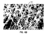
- FIG. 6B is a magnified view of the fiber layer shown in FIG. 6 A.
- FIG. 7 is a perspective schematic view of the adjustable mold used to make the sail of the present invention.
- FIG. 8 is a plan view of another embodiment.
- FIG. 9 illustrates a partial layout of yarns in a mainsail having a roach.
- the sail of the present invention is made on a mold having a 3-D surface, preferably a convex continuous adjustable surface, such as shown in FIG. 7, as described in U.S. Pat. No. 5,097,784, incorporated herein by reference.
- the mold apparatus comprises a plurality of base support members 34 , 36 and 38 , which diverge from a common point in a triangular configuration. These support members are mounted in a fixed position.
- a plurality of transverse rail members 40 are mounted on and across the base members and are adjustably movable in parallel in a direction toward and away from apex of the base members, i.e., along the center line of the angle.
- Each of the rails 40 carries a plurality of upright columns 42 which can be adjusted along various positions on the rail.
- Each of the columns 42 is preferably adjustable in height by a plurality of fluid driven devices to define a plurality of areas of support for a three dimensional profile.
- On the upper ends of each series of columns is secured a flexible flat member 44 , similar to a batten, with each batten defining a crosswise curvature.
- a plurality of upper profile members 46 which are flexible and contiguous together to define the three dimensional surface of the mold.
- These members may be made, for example, from reinforced rubber, or the sections may each comprise a tube covered with flexible plates and covered with a rubber blanket. As a result, the mold surface is substantially continuous and uninterrupted.
- the various supports are adjustable to accommodate sails of various shapes and sizes.
- the molded, three dimensional sail of the present invention comprises a laminate of at least three layers.
- the outer layers comprise continuous film layers
- the third layer is an array of yarns as described herein.
- the triangular sail of the present invention comprises a luff 10 extending between the head 12 and the tack 14 , a foot 16 between the tack and clew 18 , and a leech 20 between the head and clew.
- the sail has a triangular shape when viewed in plan but also has a molded airfoil shape and draft.
- the layout described herein is applicable to any type of sail, including mainsails, foresails, or any pliant or flexible three dimensional fabric.
- FIG. 2 illustrates the layout of the two film layers 20 and 22 .
- the film may be composed of any suitable polymer such as polyester, as well as any other films known to sailmaking.
- the yarn layers have been omitted for the sake of clarity.
- each film layer is formed from a number of pieces of film such as 24 and 26 .
- the butt joints between the pieces in each layer 20 and 22 may be offset or spaced, as shown at 28 for layer 20 and 30 for layer 22 .
- the sail is devoid of “panels” as the term is used in sailmaking, in that there are no joined seams extending through the fabric of the sail. While the film layers are impervious, they do not contribute substantially to the strength of the sail in comparison to the yarns.
- the edges of film pieces may be cut such that they can be butted together, or the edges may be overlapped. Adhesive tape may be applied to hold the pieces together during the lamination process.
- the sail is made by the same method disclosed in the aforesaid U.S. Pat. No. 5,097,784.
- a first layer of continuous film is applied to the mold, and then three layers of overlapping yarns are applied as described herein.
- the yarns may be coated with adhesive prior to application.
- the yarns are applied in a 3-D fashion.
- the inwardly facing surfaces of the film layers may also be coated with adhesive.
- composition of the yarns can be selected from any suitable type known in the sailmaking industry, such as polyester, carbon, aramid, and the like, as well as materials sold under the trademarks Spectra, Dyntema, Certran, Vectran and Zylon.
- the denier and count of the yarns are dependent on the size of the sail and its intended use.
- the yarns comprise continuous filaments and may be twisted.
- FIGS. 1, 3 , 4 and 5 illustrate the general layout pattern of yarns in the sail.
- a first plurality of yarns 32 extend from a concentrated area at the head 12 of the sail and radiate outwardly, with all of the yarns terminating at the foot 16 in spaced fashion. While the yarns 32 are shown being spaced equally at the foot 16 , other configurations can be envisioned. For example, a greater number of yarns may be applied in areas which receive more stress in the sail. Also, the yarns do not have to radiate exactly out of the apex of the corner, especially if patches are applied to the corners.
- a second plurality of yarns 50 extend from a concentrated area of the tack 14 and radiate across the width of the sail and terminate at the leech 20 .
- a third plurality of yarns 52 diverge outwardly from a concentrated area at the clew 18 in a radiating fashion and terminate at the luff 10 .
- the sail is a one piece, molded triangular three dimensional sail having three corners and three edges opposed to the corners.
- a first 32 , second 50 , and third 52 , plurality of yarns radiate from each of the corners in a radiating fashion and terminate at an opposite edge of the sail.
- the yarns are preferably substantially straight when the sail is viewed in plan and are preferably continuous along their length.
- the yarns connect corners of the sail.
- the yarns are substantially inextensible, and each set or array of yarns from each corner act independently of the other sets. Loads on the body of the sail caused by wind pressure are dissipated from the body into the corners by the shortest available route.
- the yarns in the present embodiment appear to be substantially straight when viewed in plan, but since they are applied on a 3-D surface of changing or complex curved shape, the yarns may not appear exactly straight when viewed in plan but may be considered as functionally straight.
- the yarns must be applied individually and not in the form of flat tapes or ribbons. If applied as tapes, the yarns or filaments within the tapes would not share loads equally.
- FIGS. 6A and 6B illustrate another embodiment of the present invention.
- the yarns are applied in the same tri-radial fashion as shown in FIG. 1 .
- a layer of chopped fibers 60 is applied over the yarns.
- the fibers may be applied as a uniform layer or may be more concentrated in selected areas.
- the fibers are applied in a fashion such that there is no orientation, with numerous fibers intersecting, and the fibers having a curved shape, as shown in FIGS. 6A and 6B.
- FIG. 8 illustrates another configuration of an array of yarns which can be employed from any of the corners. While it is essential that a substantial number of yarns extend from corner to an opposite edge, such as the yarns 80 , other yarns, such as 82 may radiate out of a corner and terminate at a point short of the opposite of the total distance, for example from about 40 to about 85 percent of the distance. In this embodiment, it is preferable that the short yarns alternate with at least one of the longer yarns. Also, the length of the shorter yarns should preferably be varied so as not to create artificial lines of potential stress.
- the sails as shown were substantially triangular in plan, in that the lines or edge s between corners are substantially straight lines, and the most effective deployment of the three radiating groups being as shown and described. Certain sails, however, do not have a triangular shape and may have portions which extend beyond a line d drawn between the corners.
- FIGS. 9 shows a mainsail 90 in which the rear edge or leech 92 is curved outwardly from the head to the clew and defines a relatively unsupported portion or roach 94 . While the roach 94 is normally supported by a number of spaced horizontal battens, it is also necessary or desirable that laminates made in accordance with the present invention have some yarns which curve into and out of the area of the roach for added support, since yarns which radiate out of the head and the clew in a relatively straight fashion would normally not intersect this portion of the sail.
- yarns 96 radiating out of the clew 18 may be deposited so that they follow a curved trajectory out toward the leech 92 into the area of the roach 94 and then back toward the luff.
- portions of the sail such as the foot, may be curved outwardly, in which case, the yarns can be curved into the additional area before extending toward the opposite edge.
- one of the outer film layers may itself be a laminate, with the outer layer being film and the inner layer being a light weight cloth, such as a taffeta, a scrim, a nonwoven fabric such as a light weight spunbonded fabric of polypropylene or polyester, and the like.
Abstract
Description
Claims (9)
Priority Applications (12)
| Application Number | Priority Date | Filing Date | Title |
|---|---|---|---|
| US09/598,871 US6332420B1 (en) | 2000-06-21 | 2000-06-21 | Sail of one piece three dimensional fabric |
| EP01944603A EP1294607B1 (en) | 2000-06-21 | 2001-06-19 | Improved sail of one piece three dimensional fabric |
| DE60135336T DE60135336D1 (en) | 2000-06-21 | 2001-06-19 | ONE PIECE SAIL OF THREE-DIMENSIONAL TISSUE |
| AU6699601A AU6699601A (en) | 2000-06-21 | 2001-06-19 | Improved sail of one piece three dimensional fabric |
| CA002411581A CA2411581C (en) | 2000-06-21 | 2001-06-19 | Improved sail of one piece three dimensional fabric |
| NZ523112A NZ523112A (en) | 2000-06-21 | 2001-06-19 | Sail of one piece three dimensional fabric comprising a laminated yarn structure with continuous primary load bearing yarns |
| DK01944603T DK1294607T3 (en) | 2000-06-21 | 2001-06-19 | Three-dimensional weave sails |
| AT01944603T ATE404426T1 (en) | 2000-06-21 | 2001-06-19 | ONE-PIECE SAIL MADE OF THREE-DIMENSIONAL FABRIC |
| PCT/US2001/019449 WO2001098141A1 (en) | 2000-06-21 | 2001-06-19 | Improved sail of one piece three dimensional fabric |
| JP2002503592A JP2003535771A (en) | 2000-06-21 | 2001-06-19 | sail |
| ES01944603T ES2311527T3 (en) | 2000-06-21 | 2001-06-19 | PERFECTED CANDLE OF A SINGLE PIECE OF THREE-DIMENSIONAL FABRIC. |
| AU2001266996A AU2001266996B2 (en) | 2000-06-21 | 2001-06-19 | Improved sail of one piece three dimensional fabric |
Applications Claiming Priority (1)
| Application Number | Priority Date | Filing Date | Title |
|---|---|---|---|
| US09/598,871 US6332420B1 (en) | 2000-06-21 | 2000-06-21 | Sail of one piece three dimensional fabric |
Publications (1)
| Publication Number | Publication Date |
|---|---|
| US6332420B1 true US6332420B1 (en) | 2001-12-25 |
Family
ID=24397260
Family Applications (1)
| Application Number | Title | Priority Date | Filing Date |
|---|---|---|---|
| US09/598,871 Expired - Fee Related US6332420B1 (en) | 2000-06-21 | 2000-06-21 | Sail of one piece three dimensional fabric |
Country Status (11)
| Country | Link |
|---|---|
| US (1) | US6332420B1 (en) |
| EP (1) | EP1294607B1 (en) |
| JP (1) | JP2003535771A (en) |
| AT (1) | ATE404426T1 (en) |
| AU (2) | AU6699601A (en) |
| CA (1) | CA2411581C (en) |
| DE (1) | DE60135336D1 (en) |
| DK (1) | DK1294607T3 (en) |
| ES (1) | ES2311527T3 (en) |
| NZ (1) | NZ523112A (en) |
| WO (1) | WO2001098141A1 (en) |
Cited By (11)
| Publication number | Priority date | Publication date | Assignee | Title |
|---|---|---|---|---|
| WO2003024779A2 (en) * | 2001-09-20 | 2003-03-27 | Conrad Peter G | Cast composite sail and method |
| US20050039662A1 (en) * | 2003-08-19 | 2005-02-24 | Duncan Skinner | Asymmetrical sail fabric |
| WO2005061321A3 (en) * | 2004-09-09 | 2005-10-06 | Alberto Fiorenzi | Apparatus and method to make a sail and relative sail made |
| FR2868752A1 (en) | 2004-04-09 | 2005-10-14 | Pascal Francis Raymo Rossignol | COMPOSITE MATERIALS FOR THE CONFECTION OF SAILS AND SAILS PRODUCED WITH THIS TYPE OF MATERIALS |
| US6971430B1 (en) | 2003-03-19 | 2005-12-06 | Thomas Ward Omohundro | Cast composite sail and method |
| US20060192054A1 (en) * | 2004-10-13 | 2006-08-31 | Lachenmeier Timothy T | Inflatable and deployable systems with three dimensionally reinforced membranes |
| US7479200B2 (en) | 2002-07-02 | 2009-01-20 | Createx S.A. | Method of producing reinforced, formed fabrics |
| US20090133818A1 (en) * | 2002-07-02 | 2009-05-28 | Gerard Gautier | Method of producing sails using reinforced, formed fabrics |
| US20100043689A1 (en) * | 2008-08-21 | 2010-02-25 | Madsen Kenneth M | Apparatus And Method Of Producing Reinforced Laminated Panels As A Continuous Batch |
| AU2007237295B2 (en) * | 2001-09-20 | 2010-08-26 | Thomas W. Omohundro | Cast composite sail and method |
| US20140060409A1 (en) * | 2011-05-05 | 2014-03-06 | Porcher Industries | Reinforcing textile thread for an inflatable sail, and rigging sail comprising such reinforcing textile threads |
Families Citing this family (2)
| Publication number | Priority date | Publication date | Assignee | Title |
|---|---|---|---|---|
| FR2829721B1 (en) | 2001-09-18 | 2007-02-23 | Alexandre Udin | DEVICE FOR THE THERMOFORMING MANUFACTURE OF THREE-DIMENSIONAL CURVED SAILS |
| ATE330765T1 (en) * | 2001-09-18 | 2006-07-15 | Sail Innovation | APPARATUS AND METHOD FOR PRODUCING PLATES WITH A THREE-DIMENSIONAL CURVATURE FROM A FLAT MATERIAL, FOR EXAMPLE FOR HEAT FORMING SAILS FROM A THERMOPLASTIC MATERIAL |
Citations (5)
| Publication number | Priority date | Publication date | Assignee | Title |
|---|---|---|---|---|
| US3903826A (en) * | 1973-07-13 | 1975-09-09 | Andersen Sailmakers Inc | Stretch resistant sail web |
| US4708080A (en) * | 1986-06-11 | 1987-11-24 | Sobstad Sailmakers, Inc. | Composite thread line sails |
| US4945848A (en) * | 1988-10-17 | 1990-08-07 | Linville James C | Reinforced sailcloth |
| US5097784A (en) * | 1990-08-21 | 1992-03-24 | North Sails Group, Inc. | Sail of one piece three dimensional laminated fabric having uninterrupted load bearing yarns |
| US6260497B1 (en) * | 2000-03-07 | 2001-07-17 | Fred Aivars Keire | Sail and method of manufacture |
Family Cites Families (5)
| Publication number | Priority date | Publication date | Assignee | Title |
|---|---|---|---|---|
| US4593639A (en) * | 1984-12-14 | 1986-06-10 | Sobstad Sailmakers, Inc. | Method of stress distribution in a sail and sail construction |
| EP0271215A1 (en) * | 1986-11-11 | 1988-06-15 | Larnaston Ltd. | Fore and aft sails |
| US4851953A (en) * | 1987-10-28 | 1989-07-25 | Linear Technology Corporation | Low voltage current limit loop |
| JPH06115494A (en) * | 1991-06-26 | 1994-04-26 | Thomas Sukaabara Guria | Sailer |
| US5172647A (en) * | 1991-09-26 | 1992-12-22 | Towne Yacht Survey, Inc. | Tape reinforced monofilm sail |
-
2000
- 2000-06-21 US US09/598,871 patent/US6332420B1/en not_active Expired - Fee Related
-
2001
- 2001-06-19 DK DK01944603T patent/DK1294607T3/en active
- 2001-06-19 NZ NZ523112A patent/NZ523112A/en not_active IP Right Cessation
- 2001-06-19 EP EP01944603A patent/EP1294607B1/en not_active Expired - Lifetime
- 2001-06-19 CA CA002411581A patent/CA2411581C/en not_active Expired - Fee Related
- 2001-06-19 WO PCT/US2001/019449 patent/WO2001098141A1/en active IP Right Grant
- 2001-06-19 AU AU6699601A patent/AU6699601A/en active Pending
- 2001-06-19 ES ES01944603T patent/ES2311527T3/en not_active Expired - Lifetime
- 2001-06-19 JP JP2002503592A patent/JP2003535771A/en active Pending
- 2001-06-19 AT AT01944603T patent/ATE404426T1/en active
- 2001-06-19 AU AU2001266996A patent/AU2001266996B2/en not_active Ceased
- 2001-06-19 DE DE60135336T patent/DE60135336D1/en not_active Expired - Lifetime
Patent Citations (6)
| Publication number | Priority date | Publication date | Assignee | Title |
|---|---|---|---|---|
| US3903826A (en) * | 1973-07-13 | 1975-09-09 | Andersen Sailmakers Inc | Stretch resistant sail web |
| US4708080A (en) * | 1986-06-11 | 1987-11-24 | Sobstad Sailmakers, Inc. | Composite thread line sails |
| US4708080B1 (en) * | 1986-06-11 | 1990-09-25 | Ctl Inc | |
| US4945848A (en) * | 1988-10-17 | 1990-08-07 | Linville James C | Reinforced sailcloth |
| US5097784A (en) * | 1990-08-21 | 1992-03-24 | North Sails Group, Inc. | Sail of one piece three dimensional laminated fabric having uninterrupted load bearing yarns |
| US6260497B1 (en) * | 2000-03-07 | 2001-07-17 | Fred Aivars Keire | Sail and method of manufacture |
Cited By (32)
| Publication number | Priority date | Publication date | Assignee | Title |
|---|---|---|---|---|
| AU2007237295B2 (en) * | 2001-09-20 | 2010-08-26 | Thomas W. Omohundro | Cast composite sail and method |
| WO2003024779A3 (en) * | 2001-09-20 | 2003-09-04 | Peter G Conrad | Cast composite sail and method |
| AU2002327672B2 (en) * | 2001-09-20 | 2008-01-31 | Omohundro, Thomas W. | Cast composite sail and method |
| WO2003024779A2 (en) * | 2001-09-20 | 2003-03-27 | Conrad Peter G | Cast composite sail and method |
| US20090173432A1 (en) * | 2002-07-02 | 2009-07-09 | Createx S.A. | Method of producing reinforced, formed fabrics |
| US8181587B2 (en) | 2002-07-02 | 2012-05-22 | Createx S.A. | Method of producing reinforced, formed fabrics |
| US8506739B2 (en) | 2002-07-02 | 2013-08-13 | Createx S.A. | Method of producing sails using reinforced, formed fabrics |
| US20090173266A1 (en) * | 2002-07-02 | 2009-07-09 | Createx S.A. | Method of producing reinforced, formed fabrics |
| US20090173267A1 (en) * | 2002-07-02 | 2009-07-09 | Createx S.A. | Method of producing reinforced, formed fabrics |
| US8709186B2 (en) | 2002-07-02 | 2014-04-29 | Createx S.A. | Method of producing reinforced, formed fabrics |
| US20090140455A1 (en) * | 2002-07-02 | 2009-06-04 | Createx S.A. | Method of producing reinforced, formed fabrics |
| US20090133818A1 (en) * | 2002-07-02 | 2009-05-28 | Gerard Gautier | Method of producing sails using reinforced, formed fabrics |
| US7479200B2 (en) | 2002-07-02 | 2009-01-20 | Createx S.A. | Method of producing reinforced, formed fabrics |
| US6971430B1 (en) | 2003-03-19 | 2005-12-06 | Thomas Ward Omohundro | Cast composite sail and method |
| US20090218727A1 (en) * | 2003-03-19 | 2009-09-03 | Thomas Ward Omohundro | Cast composite sail and method |
| US7419561B1 (en) | 2003-03-19 | 2008-09-02 | Thomas Ward Omohundro | Cast composite sail and method |
| US7490570B2 (en) | 2003-08-19 | 2009-02-17 | Contender U.S., Inc. | Asymmetrical sail fabric |
| US7104210B2 (en) * | 2003-08-19 | 2006-09-12 | Contender U.S., Inc. | Asymmetrical sail fabric |
| US20050039662A1 (en) * | 2003-08-19 | 2005-02-24 | Duncan Skinner | Asymmetrical sail fabric |
| US20080066667A1 (en) * | 2003-08-19 | 2008-03-20 | Contender U.S., Inc. | Asymmetrical Sail Fabric |
| US7305927B2 (en) | 2003-08-19 | 2007-12-11 | Contender U.S., Inc. | Asymmetrical sail fabric |
| US7658160B2 (en) | 2003-08-19 | 2010-02-09 | Contender U.S., Inc. | Asymmetrical sail fabric |
| US20070022933A1 (en) * | 2003-08-19 | 2007-02-01 | Duncan Skinner | Asymmetrical Sail Fabric |
| US20090114135A1 (en) * | 2003-08-19 | 2009-05-07 | Contender U.S., Inc. | Asymmetrical Sail Fabric |
| FR2868752A1 (en) | 2004-04-09 | 2005-10-14 | Pascal Francis Raymo Rossignol | COMPOSITE MATERIALS FOR THE CONFECTION OF SAILS AND SAILS PRODUCED WITH THIS TYPE OF MATERIALS |
| US20070256621A1 (en) * | 2004-09-09 | 2007-11-08 | Alberto Fiorenzi | Apparatus and Method to Make a Sail and Relative Sail Made |
| WO2005061321A3 (en) * | 2004-09-09 | 2005-10-06 | Alberto Fiorenzi | Apparatus and method to make a sail and relative sail made |
| US7383783B2 (en) | 2004-09-09 | 2008-06-10 | Alberto Fiorenzi | Apparatus and method to make a sail and relative sail made |
| US20060192054A1 (en) * | 2004-10-13 | 2006-08-31 | Lachenmeier Timothy T | Inflatable and deployable systems with three dimensionally reinforced membranes |
| US20100043689A1 (en) * | 2008-08-21 | 2010-02-25 | Madsen Kenneth M | Apparatus And Method Of Producing Reinforced Laminated Panels As A Continuous Batch |
| US20140060409A1 (en) * | 2011-05-05 | 2014-03-06 | Porcher Industries | Reinforcing textile thread for an inflatable sail, and rigging sail comprising such reinforcing textile threads |
| US9234305B2 (en) * | 2011-05-05 | 2016-01-12 | Porcher Industries | Reinforcing textile thread for an inflatable sail, and rigging sail comprising such reinforcing textile threads |
Also Published As
| Publication number | Publication date |
|---|---|
| NZ523112A (en) | 2005-03-24 |
| JP2003535771A (en) | 2003-12-02 |
| AU6699601A (en) | 2002-01-02 |
| EP1294607A1 (en) | 2003-03-26 |
| AU2001266996B2 (en) | 2005-10-20 |
| ATE404426T1 (en) | 2008-08-15 |
| DE60135336D1 (en) | 2008-09-25 |
| WO2001098141A1 (en) | 2001-12-27 |
| DK1294607T3 (en) | 2008-12-08 |
| EP1294607A4 (en) | 2006-09-13 |
| EP1294607B1 (en) | 2008-08-13 |
| CA2411581C (en) | 2008-09-09 |
| CA2411581A1 (en) | 2001-12-27 |
| ES2311527T3 (en) | 2009-02-16 |
Similar Documents
| Publication | Publication Date | Title |
|---|---|---|
| US5001003A (en) | Laminated sailcloth with scrim | |
| CA2049657C (en) | Sail of one piece three dimensional laminated fabric having uninterrupted load bearing yarns | |
| US5097783A (en) | Reinforced sailcloth | |
| US6332420B1 (en) | Sail of one piece three dimensional fabric | |
| US4945848A (en) | Reinforced sailcloth | |
| US4679519A (en) | Laminated cloth construction | |
| AU747021B2 (en) | Composite products, methods and apparatus | |
| US7658160B2 (en) | Asymmetrical sail fabric | |
| US4624205A (en) | Method of stress distribution in a sail, a sail embodying the same and sail construction | |
| AU2001266996A1 (en) | Improved sail of one piece three dimensional fabric | |
| JPS61247591A (en) | Sail | |
| EP0224729A1 (en) | A sail | |
| US6302045B1 (en) | Three layer molded sail construction | |
| EP2920057B1 (en) | Integral sail and corresponding method of production | |
| US5323725A (en) | Spinnaker | |
| US5097782A (en) | Sail with reinforced batten pocket ends | |
| WO2004041636A1 (en) | Three-dimensional sail with laminated structure and construction method |
Legal Events
| Date | Code | Title | Description |
|---|---|---|---|
| AS | Assignment |
Owner name: NORTH MARINE GROUP, CONNECTICUT Free format text: ASSIGNMENT OF ASSIGNORS INTEREST;ASSIGNOR:RODGERS, JOHN H.;REEL/FRAME:011215/0686 Effective date: 20000926 |
|
| FEPP | Fee payment procedure |
Free format text: PAYOR NUMBER ASSIGNED (ORIGINAL EVENT CODE: ASPN); ENTITY STATUS OF PATENT OWNER: LARGE ENTITY |
|
| FPAY | Fee payment |
Year of fee payment: 4 |
|
| FEPP | Fee payment procedure |
Free format text: PAYOR NUMBER ASSIGNED (ORIGINAL EVENT CODE: ASPN); ENTITY STATUS OF PATENT OWNER: LARGE ENTITY Free format text: PAYER NUMBER DE-ASSIGNED (ORIGINAL EVENT CODE: RMPN); ENTITY STATUS OF PATENT OWNER: LARGE ENTITY |
|
| FPAY | Fee payment |
Year of fee payment: 8 |
|
| REMI | Maintenance fee reminder mailed | ||
| LAPS | Lapse for failure to pay maintenance fees | ||
| STCH | Information on status: patent discontinuation |
Free format text: PATENT EXPIRED DUE TO NONPAYMENT OF MAINTENANCE FEES UNDER 37 CFR 1.362 |
|
| FP | Lapsed due to failure to pay maintenance fee |
Effective date: 20131225 |
|
| AS | Assignment |
Owner name: NXT CAPITAL, LLC, AS AGENT, ILLINOIS Free format text: SECURITY AGREEMENT;ASSIGNORS:NORTH SAILS GROUP, LLC;SOUTHERN SPARS GROUP, LLC;NORTH TECHNOLOGY GROUP, LLC;REEL/FRAME:032389/0355 Effective date: 20140305 |