US6278735B1 - Real-time single pass variable bit rate control strategy and encoder - Google Patents

Real-time single pass variable bit rate control strategy and encoder Download PDF

Info

Publication number
US6278735B1
US6278735B1 US09/044,642 US4464298A US6278735B1 US 6278735 B1 US6278735 B1 US 6278735B1 US 4464298 A US4464298 A US 4464298A US 6278735 B1 US6278735 B1 US 6278735B1
Authority
US
United States
Prior art keywords
frames
overscore
bits
encoding
bit rate
Prior art date
Legal status (The legal status is an assumption and is not a legal conclusion. Google has not performed a legal analysis and makes no representation as to the accuracy of the status listed.)
Expired - Fee Related
Application number
US09/044,642
Inventor
Nader Mohsenian
Current Assignee (The listed assignees may be inaccurate. Google has not performed a legal analysis and makes no representation or warranty as to the accuracy of the list.)
International Business Machines Corp
Original Assignee
International Business Machines Corp
Priority date (The priority date is an assumption and is not a legal conclusion. Google has not performed a legal analysis and makes no representation as to the accuracy of the date listed.)
Filing date
Publication date
Application filed by International Business Machines Corp filed Critical International Business Machines Corp
Priority to US09/044,642 priority Critical patent/US6278735B1/en
Assigned to INTERNATIONAL BUSINESS MACHINES CORPORATION reassignment INTERNATIONAL BUSINESS MACHINES CORPORATION ASSIGNMENT OF ASSIGNORS INTEREST (SEE DOCUMENT FOR DETAILS). Assignors: MOHSENIAN, NADER
Priority to TW087110219A priority patent/TW404132B/en
Priority to KR1019990005614A priority patent/KR100305941B1/en
Priority to SG9901279A priority patent/SG80615A1/en
Priority to JP11063139A priority patent/JPH11346362A/en
Application granted granted Critical
Publication of US6278735B1 publication Critical patent/US6278735B1/en
Anticipated expiration legal-status Critical
Expired - Fee Related legal-status Critical Current

Links

Images

Classifications

    • HELECTRICITY
    • H04ELECTRIC COMMUNICATION TECHNIQUE
    • H04NPICTORIAL COMMUNICATION, e.g. TELEVISION
    • H04N19/00Methods or arrangements for coding, decoding, compressing or decompressing digital video signals
    • H04N19/10Methods or arrangements for coding, decoding, compressing or decompressing digital video signals using adaptive coding
    • H04N19/134Methods or arrangements for coding, decoding, compressing or decompressing digital video signals using adaptive coding characterised by the element, parameter or criterion affecting or controlling the adaptive coding
    • HELECTRICITY
    • H04ELECTRIC COMMUNICATION TECHNIQUE
    • H04NPICTORIAL COMMUNICATION, e.g. TELEVISION
    • H04N19/00Methods or arrangements for coding, decoding, compressing or decompressing digital video signals
    • H04N19/80Details of filtering operations specially adapted for video compression, e.g. for pixel interpolation
    • HELECTRICITY
    • H04ELECTRIC COMMUNICATION TECHNIQUE
    • H04NPICTORIAL COMMUNICATION, e.g. TELEVISION
    • H04N19/00Methods or arrangements for coding, decoding, compressing or decompressing digital video signals
    • H04N19/10Methods or arrangements for coding, decoding, compressing or decompressing digital video signals using adaptive coding
    • H04N19/102Methods or arrangements for coding, decoding, compressing or decompressing digital video signals using adaptive coding characterised by the element, parameter or selection affected or controlled by the adaptive coding
    • H04N19/115Selection of the code volume for a coding unit prior to coding
    • HELECTRICITY
    • H04ELECTRIC COMMUNICATION TECHNIQUE
    • H04NPICTORIAL COMMUNICATION, e.g. TELEVISION
    • H04N19/00Methods or arrangements for coding, decoding, compressing or decompressing digital video signals
    • H04N19/10Methods or arrangements for coding, decoding, compressing or decompressing digital video signals using adaptive coding
    • H04N19/134Methods or arrangements for coding, decoding, compressing or decompressing digital video signals using adaptive coding characterised by the element, parameter or criterion affecting or controlling the adaptive coding
    • H04N19/136Incoming video signal characteristics or properties
    • H04N19/14Coding unit complexity, e.g. amount of activity or edge presence estimation
    • HELECTRICITY
    • H04ELECTRIC COMMUNICATION TECHNIQUE
    • H04NPICTORIAL COMMUNICATION, e.g. TELEVISION
    • H04N19/00Methods or arrangements for coding, decoding, compressing or decompressing digital video signals
    • H04N19/10Methods or arrangements for coding, decoding, compressing or decompressing digital video signals using adaptive coding
    • H04N19/134Methods or arrangements for coding, decoding, compressing or decompressing digital video signals using adaptive coding characterised by the element, parameter or criterion affecting or controlling the adaptive coding
    • H04N19/146Data rate or code amount at the encoder output
    • H04N19/152Data rate or code amount at the encoder output by measuring the fullness of the transmission buffer
    • HELECTRICITY
    • H04ELECTRIC COMMUNICATION TECHNIQUE
    • H04NPICTORIAL COMMUNICATION, e.g. TELEVISION
    • H04N19/00Methods or arrangements for coding, decoding, compressing or decompressing digital video signals
    • H04N19/10Methods or arrangements for coding, decoding, compressing or decompressing digital video signals using adaptive coding
    • H04N19/169Methods or arrangements for coding, decoding, compressing or decompressing digital video signals using adaptive coding characterised by the coding unit, i.e. the structural portion or semantic portion of the video signal being the object or the subject of the adaptive coding
    • H04N19/17Methods or arrangements for coding, decoding, compressing or decompressing digital video signals using adaptive coding characterised by the coding unit, i.e. the structural portion or semantic portion of the video signal being the object or the subject of the adaptive coding the unit being an image region, e.g. an object
    • H04N19/176Methods or arrangements for coding, decoding, compressing or decompressing digital video signals using adaptive coding characterised by the coding unit, i.e. the structural portion or semantic portion of the video signal being the object or the subject of the adaptive coding the unit being an image region, e.g. an object the region being a block, e.g. a macroblock
    • HELECTRICITY
    • H04ELECTRIC COMMUNICATION TECHNIQUE
    • H04NPICTORIAL COMMUNICATION, e.g. TELEVISION
    • H04N19/00Methods or arrangements for coding, decoding, compressing or decompressing digital video signals
    • H04N19/10Methods or arrangements for coding, decoding, compressing or decompressing digital video signals using adaptive coding
    • H04N19/169Methods or arrangements for coding, decoding, compressing or decompressing digital video signals using adaptive coding characterised by the coding unit, i.e. the structural portion or semantic portion of the video signal being the object or the subject of the adaptive coding
    • H04N19/177Methods or arrangements for coding, decoding, compressing or decompressing digital video signals using adaptive coding characterised by the coding unit, i.e. the structural portion or semantic portion of the video signal being the object or the subject of the adaptive coding the unit being a group of pictures [GOP]
    • HELECTRICITY
    • H04ELECTRIC COMMUNICATION TECHNIQUE
    • H04NPICTORIAL COMMUNICATION, e.g. TELEVISION
    • H04N19/00Methods or arrangements for coding, decoding, compressing or decompressing digital video signals
    • H04N19/50Methods or arrangements for coding, decoding, compressing or decompressing digital video signals using predictive coding
    • H04N19/503Methods or arrangements for coding, decoding, compressing or decompressing digital video signals using predictive coding involving temporal prediction
    • H04N19/51Motion estimation or motion compensation
    • HELECTRICITY
    • H04ELECTRIC COMMUNICATION TECHNIQUE
    • H04NPICTORIAL COMMUNICATION, e.g. TELEVISION
    • H04N19/00Methods or arrangements for coding, decoding, compressing or decompressing digital video signals
    • H04N19/60Methods or arrangements for coding, decoding, compressing or decompressing digital video signals using transform coding
    • H04N19/61Methods or arrangements for coding, decoding, compressing or decompressing digital video signals using transform coding in combination with predictive coding
    • HELECTRICITY
    • H04ELECTRIC COMMUNICATION TECHNIQUE
    • H04NPICTORIAL COMMUNICATION, e.g. TELEVISION
    • H04N19/00Methods or arrangements for coding, decoding, compressing or decompressing digital video signals
    • H04N19/10Methods or arrangements for coding, decoding, compressing or decompressing digital video signals using adaptive coding
    • H04N19/134Methods or arrangements for coding, decoding, compressing or decompressing digital video signals using adaptive coding characterised by the element, parameter or criterion affecting or controlling the adaptive coding
    • H04N19/146Data rate or code amount at the encoder output
    • H04N19/149Data rate or code amount at the encoder output by estimating the code amount by means of a model, e.g. mathematical model or statistical model
    • HELECTRICITY
    • H04ELECTRIC COMMUNICATION TECHNIQUE
    • H04NPICTORIAL COMMUNICATION, e.g. TELEVISION
    • H04N19/00Methods or arrangements for coding, decoding, compressing or decompressing digital video signals
    • H04N19/10Methods or arrangements for coding, decoding, compressing or decompressing digital video signals using adaptive coding
    • H04N19/134Methods or arrangements for coding, decoding, compressing or decompressing digital video signals using adaptive coding characterised by the element, parameter or criterion affecting or controlling the adaptive coding
    • H04N19/146Data rate or code amount at the encoder output
    • H04N19/15Data rate or code amount at the encoder output by monitoring actual compressed data size at the memory before deciding storage at the transmission buffer

Definitions

  • This invention relates, in general, to the field of digital video compression, and in particular, to a rate-control technique suitable for real-time single-pass variable bit rate encoding in a video compression system which employs the MPEG-2 international standard.
  • Digital video compression solutions are arguably the most important component of any digital video platform. Since digital video is known to contain an enormous amount of information in uncompressed format, its manipulation, storage, and transmission can become very time consuming and expensive, if not impossible. As a result, digital video compression techniques are needed to reduce the overwhelming volume of the data while preserving the perceptual quality of its content. A compatible video decompression scheme is then used to uncompress the data for playback.
  • This standard specifies the syntax of the encoded stream and a technique of decoding. It offers great flexibility to the encoder designer allowing the designer to derive his/her own set of compression parameters, and therefore, distinguish his/her product from the rest of the encoders developed by other manufacturers.
  • the efficiency of the MPEG-2 encoding system is assessed by the fidelity of the perceived video transmitted over a fixed communications bandwidth or stored into a digital medium.
  • multiple programs are multiplexed into a single large stream for broadcasting, and a bank of MPEG-2 encoders are used to monitor and encode all programs, while maintaining the quality of all received channels.
  • the MPEG-2 stream is sent over either a fixed communications bandwidth or a dynamic bandwidth as in asynchronous transfer mode (ATM) networks.
  • ATM asynchronous transfer mode
  • a video stream includes a plurality of pictures or frames of various types, such as I, B and P picture types.
  • a picture depending on its type, may consume more or less bits than the set target rate of the video stream.
  • the CBR rate-control strategy has the responsibility of maintaining a bit ratio between the different picture types of the stream, such that the desired average bit rate is satisfied, and a high quality video sequence is displayed.
  • VBR variable bit rate
  • Other encoders including other MPEG-2 encoders, perform in a different mode, defined as a variable bit rate (VBR) mode.
  • VBR variable bit rate
  • Variable bit rate encoding allows each compressed picture to have a different amount of bits based on the complexity of intra and inter-picture characteristics. For example, the encoding of scenes with simple picture content (such as a color test pattern) will consume significantly less bits than scenes with complicated picture content (such as a crowded city street), in order to achieve the same picture quality.
  • VBR encoding is conventionally accomplished in non-real time using two or more passes. In a first pass, encoding is performed and statistics are gathered and analyzed, and in a second pass, the results of the analysis are used to control the encoding process. Although this produces a high quality compressed video stream, it does not allow for real-time operation, nor does it allow for single pass encoding.
  • the shortcomings of the prior art are overcome and additional advantages are provided through the provision of a method of processing groups of frames.
  • the method includes, for instance, encoding at least one group of frames of an input stream, and determining, prior to encoding the entire input stream, a number of bits to be allocated to another group of frames of the input stream.
  • the another group of frames is to be encoded in a variable bit rate mode.
  • the determining uses one or more parameter of values obtained from the encoding.
  • the method includes encoding the another group of frames in a single pass variable bit rate mode, wherein the another group of frames is encoded in only one encoding pass.
  • the determining includes modulating, for the another group of frames, a slope of a predefined perceptual function, and using the modulated slope in a bit rate equation to determine the number of bits to be allocated.
  • the determining includes determining, for the another group of frames, a translation factor for a predefined perceptual function, and using the translation factor in a bit rate equation to determine the number of bits.
  • the determining includes compensating for one or more instability conditions of the input stream, and in a further embodiment, the determining includes using a predefined function to determine the number of bits.
  • a method of processing groups of frames includes, for example, determining a plurality of parameter values from one or more previously encoded group of frames; computing, for a group of frames to be encoded, in a single pass variable bit rate mode, a slope of a predefined function, in which the computing uses one or more of the plurality of parameter values; and obtaining a bit rate for the group of frames to be encoded, using the computed slope and one or more of the plurality of parameter values.
  • a method of processing groups of frames includes, for instance, determining a number of bits to be allocated to a group of frames of an input stream.
  • the determining uses an instantaneous rate-quantization behavior of the group of frames and a perceptual model indicating a complexity of the group of frames.
  • the method further includes encoding the group of frames using a variable bit rate mode at a rate defined by the determining.
  • a single pass variable bit rate encoder includes, for example, an encoding engine adapted to encode at least one group of frames of an input stream; and means for determining, prior to encoding the entire input stream, a number of bits to be allocated to another group of frames of the input stream.
  • the another group of frames is to be encoded in a variable bit rate mode.
  • the means for determining uses one or more parameter values obtained from the encoding engine.
  • a single pass variable bit rate encoder which includes, for instance, means for determining a plurality of parameter values for one or more previously encoded group of frames; means for computing, for a group of frames to be encoded in a single pass variable bit rate mode, a slope of a predefined function, in which one or more of the plurality of parameter values is used; and means for obtaining a bit rate for the group of frames to be encoded, using the computed slope and one or more of the plurality of parameter values.
  • a single pass variable bit rate encoder which includes, for instance, means for determining a number of bits to be allocated to a group of frames of an input stream, in which the means for determining uses an instantaneous rate-quantization behavior of the group of frames and a perceptual model indicating a complexity of the group of frames; and an encoding engine adapted to encode the group of frames using a variable bit rate mode at a rate defined by the means for determining.
  • the present invention is particularly useful for applications where one cannot pre-analyze or pre-encode the video, as in in-home production for digital video disks (DVD's), digital video cassette recorders (DVCR's), computer multimedia, and digital camcorders.
  • a single-pass VBR encoder only uses the previously encoded pictures to make an assumption about the complexity of a picture to be encoded. This is in contrast to multi-pass VBR video compression, used in high-end DVD mastering, where a video source may be pre-analyzed and encoded several times to create an optimal compressed stream for a particular storage medium. Therefore, a single-pass VBR encoder relies on a causal predictive model to dynamically adjust the average rate of the stream and produce high fidelity video.
  • FIG. 1 depicts one example of a block diagram of an MPEG-2 encoder incorporating and using the real-time single pass variable bit rate control strategy of the present invention
  • FIG. 2 depicts one example of a block diagram of motion estimation tasks for P and B picture types
  • FIG. 3 depicts one example of the ⁇ overscore (C) ⁇ - ⁇ overscore (Q) ⁇ models and the operating points of a variable bit rate control technique of the present invention
  • FIG. 4 depicts one embodiment of the logic associated with one example of estimating the number of bits to be allocated to a group of pictures (GOP), in accordance with the principles of the present invention
  • FIG. 5 depicts one example of a block diagram of one embodiment of the variable bit rate control strategy of the present invention
  • FIG. 6 depicts one embodiment of the logic associated with another example of estimating the number of bits to be allocated to a group of pictures, in accordance with the principles of the present invention
  • FIG. 7 depicts one example of the ⁇ overscore (C) ⁇ - ⁇ overscore (Q) ⁇ models and the operating points of another variable bit rate control technique of the present invention
  • FIG. 8 depicts one example of GOP bits adjustment during a scene transition using a MEDIAN filtering technique of the present invention.
  • FIG. 9 depicts one example of GOP bits adjustment for rate control instabilities, in accordance with the principles of the present invention.
  • a rate-control strategy for real-time single pass variable bit rate (VBR) encoding is provided, which is easily implementable in hardware and may be incorporated in, for instance, any MPEG-2 compression system.
  • VBR variable bit rate
  • FIG. 1 depicts various image and signal processing tasks used by the encoder to encode a video stream and to decode the compressed stream.
  • MPEG-2 encoder 100 is a sophisticated information processor including spatial and temporal image analyzers, quantizers, entropy coders, and a rate control policy that ensures the creation of a fully compliant video stream which meets the demand of a chosen application.
  • Each luminance picture of a video stream is partitioned into non-overlapping blocks of 16 ⁇ 16 pixels, which in turn are sub-divided into four 8 ⁇ 8 blocks.
  • the two chrominance pictures result in four or two 8 ⁇ 8 blocks, depending on the 4:2:2: or 4:2:0 chrominance sampling.
  • the set containing all luminance and chrominance blocks is called a macroblock (MB).
  • a 4:2:2 macroblock has eight blocks, while the 4:2:0 macroblock has six.
  • Each 8 ⁇ 8 block of pixels is transformed to frequency domain, using a two-dimensional discrete cosine transformation (DCT) 102 .
  • DCT discrete cosine transformation
  • DCT is intended to perform an energy compaction on input blocks by obtaining classes of high priority (low) frequency coefficients and low priority (high) frequency coefficients. It is a fast and efficient way of removing some of the spatial redundancies of the image blocks.
  • Temporal redundancies are removed via a technique called motion estimation (ME) 104 .
  • ME motion estimation
  • any luminance macroblock can be predicted by moving a correspondent macroblock, which belongs to a previous picture, within a search window.
  • the procedure of searching for the best macroblock match is defined as motion estimation.
  • This best match (prediction) is then subtracted from the macroblock under consideration and a DCT transformation is applied to the macroblock difference.
  • a motion vector 106 is created, which points to the location of the predicted macroblock.
  • the motion vector (MV) is used by both the encoder and the decoder to motion compensate (MC) 108 the correspondent macroblock and locate the best match.
  • Motion estimation is implemented only on the luminance portion of the macroblock, with the resulting motion vector scaled and used to motion compensate the chrominance block pairs.
  • the encoding of the motion vectors is carried out, employing a technique known as differential pulse code modulation (DPCM), where a motion vector is predicted using the motion vector of a previously encoded macroblock, and only the difference between the motion vector and its prediction is encoded.
  • DPCM differential pulse code modulation
  • Motion vector differences are represented with code words defined in look-up tables of the MPEG-2 standard.
  • the MPEG-2 standard uses I (Intra-Coded), P (Predicted) and B (Bidirectionally-Predicted) type pictures, as shown in FIG. 2 .
  • the Intra-Coded I's use only the information within that picture, while the P types employ the motion estimation and compensation tasks performed on previously encoded I or P types to predict a macroblock 200 and compute a prediction error to be encoded. This is an efficient way of compression, since the motion compensated macroblock differences contain less information than the original macroblock.
  • a motion vector MV p f 202 is used to find the best match for a macroblock 200 in picture P, which resides in picture I and within a search window 204 (denoted in FIG. 2 by the dashed lines).
  • B type pictures use information from both previous and future I or P types for forward and backward predictions and are particularly useful for estimating objects that move in different directions with different velocities. Further, the bidirectional motion estimation schemes used in B pictures are more robust in noisy environments, as compared to the causal prediction used for P types. This is because both predictions can be used simultaneously by averaging their nominal values.
  • the task of motion estimation for macroblock 200 in picture B 1 consists of a forward prediction represented by MV B1 f and a backward prediction, represented by MV B1 b .
  • forward and backward predictions are represented by MV B2 f and MV B2 b , respectively.
  • the various picture types are quantized 110 (FIG. 1) by encoder 100 in several steps.
  • a quantization matrix unique to a picture type, is applied to an 8 ⁇ 8 DCT block.
  • the elements (weights) of the matrix are chosen such that importance is given to low frequency coefficients. These coefficients contain more information and contribute more to the perceptual quality of the picture.
  • a quantization scaling factor is computed to classify the macroblocks into different classes, based on the local image activity, complexity of the picture type, and a measure of buffer fullness. This index is directly related to the number of bits allocated to a picture and its perceived quality.
  • the actual number of bits is obtained by first scanning 112 each DCT block and then grouping the quantized alternate current (AC) coefficients together, according to the procedures defined in the MPEG-2 standard. Each group is entropy coded 114 with a unique variable length code (VLC), using a Huffman look-up table. Direct current (DC) coefficients are encoded, employing DPCM (similar to encoding of MV's) and uniform quantization.
  • AC alternate current
  • the output of the entropy coder 114 is input to entropy decoder 116 .
  • the output of decoder 116 goes through an inverse scan 118 , inverse quantization 120 and inverse discrete cosine transformation 122 to return a lossy version of the difference macroblock.
  • the decoded picture is then passed through a delay 124 to motion estimation 104 and/or motion compensation 108 , as is known in the art.
  • a decoder buffer is used to absorb the rate fluctuations and convert the fixed channel rate into compressed picture bits and deliver it to an actual decoder for processing. Therefore, in one embodiment of the rate-control strategy of the present invention, the level of buffer occupancy is tracked, as well as the complexity of the picture and the local activity of the image macroblock, as described in detail below.
  • Encoder 100 further includes a rate control policy used in the creation of a fully compliant stream that meets the demand of a chosen application.
  • the rate control policy of encoder 100 includes a variable bit rate (VBR) encoding scheme used to encode the frames of an input stream (e.g., a video stream).
  • VBR variable bit rate
  • some rate control fundamentals are discussed in order to enhance the understanding of the present invention. These fundamentals relate to constant bit rate (CBR) encoding schemes.
  • An MPEG-2 sequence is typically partitioned into small intervals, such as group of pictures (GOP's) or frames, which in turn are categorized by picture types I, P, and B.
  • the number of bits per GOP is distributed such that an I picture allocation is more than a P. This is because a P picture uses the motion estimation technique to estimate its content and, as a result, a motion compensated frame difference (MCFD), with a lower entropy than the original source, is encoded.
  • B pictures use the least amount of bits, since their motion estimation techniques are more intensive than P's. This provides a basis for maintaining the same picture quality within a GOP, when pictures of different types are encoded. Further, the bit allocation of B pictures can be lowered, since they will not be used to estimate other pictures.
  • An encoded GOP starts with an I picture type. The amount of bits assigned to a picture type x,(x ⁇ I,P,B ⁇ ) is inversely related to the amount of distortion perceived in the picture quality of that type.
  • X x is a pre-defined measure of complexity for each picture type.
  • index k denotes the GOP number
  • x is the picture type
  • N x is the number of pictures of type x in a GOP
  • R x is the target picture bits for type x.
  • C k C gop , where C gop is a fixed GOP bits.
  • C gop is a fixed GOP bits.
  • Targets in equation (5) represent the ideal picture bits and the actual bits would almost always deviate from this.
  • the accumulated error is computed and fed back to the constant bit rate control technique to ensure that the final MPEG-2 bitstream meets the average bit rate or the total bit budget.
  • complexity measures X x 's are updated and a new target based on equation (7) is computed for the next picture. This target should meet certain constraints, as described below, to ensure that the decoder buffer does not experience overflow or underflow conditions.
  • VBR real-time single pass VBR techniques
  • the CBR rate control technique of section 1 is motivated by the fact that for a fixed target C gop , constant quality is achieved within a GOP by modulating the quantization parameters. Any statistical variations or bit offshoots are exploited to help stabilize the CBR rate control technique over time and maintain a desired rate.
  • an MPEG-2 CBR encoder takes advantage of a set of universal constants and pre-determined initial complexity measures to maintain a certain ratio between the amount of bits allocated among different picture types.
  • efforts in classifying a group of continuous pictures, such as GOP's or video segments, into different types of time intervals in terms of complexity hardness or softness, have been limited for real-time single-pass MPEG-2 encoding. Hardness (softness) of the video is defined by a large (small) amount of bits that it requires to produce high fidelity results. For multi-pass CBR or multi-pass VBR encoding, such information is known and hence, quality improvements can be made.
  • the real time single-pass VBR encoder of the present invention exploits a ( ⁇ overscore (C) ⁇ - ⁇ overscore (Q) ⁇ ) perceptual model to differentiate the hardness or softness of video segments, each corresponding to a particular hyperbola defined by equation (1).
  • the actual ( ⁇ overscore (C) ⁇ , ⁇ overscore (Q) ⁇ ) pairs are then computed along this hyperbola.
  • each video segment i.e., each GOP
  • this difficulty can be measured by various source statistics or compression parameters, such as total picture bits, quantization scaler, spatial activity, temporal activity, signal to noise ratio, or any combination of the above.
  • a larger amount of bits should be allocated to a video segment with a high level of encoding difficulty.
  • This is a different approach than the CBR rate control technique, where a fixed number of bits is allocated to each GOP, regardless of the degree of complexity of the source.
  • Research efforts have shown that for a large number of test cases composed of complex, moderate and easy materials, a strong correlation exists between the rate of the video interval and the quantization scaler.
  • the R a -Q a relationship of (8) is deduced based on the criterion that all types of video intervals should be perceived equally. Further, it suggests that difficult video segments producing a large quantization scaler, Q, should consume more than an average bit rate of the compressed stream, while easy segments would use a smaller number of bits. This relationship provides a building block in formulating a robust single pass VBR encoding technique, since it takes advantage of the variability of the video source.
  • the actual number of bits allocated to each interval (e.g., each GOP) is determined, in accordance with the principles of the present invention, by the slope K of the following perceptual model:
  • R a K ( a 1 +a 2 Q a ⁇ ) (9).
  • constant K (measured in Mbits/s) is modulated, for each video interval (i.e., each GOP), to ensure the average rate of the compressed stream meets the desired target rate.
  • K is described further below.
  • the efficiency of a single pass VBR encoder is assessed by how fast its rate control technique can learn and adjust itself to the softness or hardness of the video stream. For regions where image discontinuity or special effects occur, degradations in picture quality should be minimized. Since, for single pass encoding, image statistics are limited by the previously analyzed and encoded pictures, the learning rate of the rate control technique should be adequate enough to predict the content of the future video intervals, yet not be too aggressive to result in algorithmic instabilities.
  • One way to solve the twofold problem is to adjust the quality of the encoded stream for every time interval (i.e., every GOP) and let the rate control technique learn the local content of each picture within that time interval.
  • Equation (10) defines the instantaneous rate-quantization behavior of a particular GOP under analysis.
  • the linear model of equation (10) and its relationship to the perceptual model of equation ( 9 a ) are depicted in FIG. 3 .
  • equation (10) is solved together with the perceptual model of equation ( 9 a ).
  • ideal operating point 3 is obtained from solving the equations with ( ⁇ overscore (C) ⁇ 1 , ⁇ overscore (Q) ⁇ 1 ) and ( ⁇ overscore (C) ⁇ 2 , ⁇ overscore (Q) ⁇ 2 )
  • ideal operating point 4 is obtained from solving the equations with ( ⁇ overscore (C) ⁇ 2 , ⁇ overscore (Q) ⁇ 2 ) and ( ⁇ overscore (C) ⁇ 3 , ⁇ overscore (Q) ⁇ 3 ).
  • a next GOP is encoded at the average bits of:
  • C _ k K ⁇ ( ⁇ k ⁇ a 1 + ⁇ k ⁇ a 2 ) f ⁇ ⁇ ⁇ k + a 2 ⁇ K . ( 11 )
  • N gop is the number of GOP's in the input sequence and G is the GOP size.
  • the denominator of equation (12) can be easily computed in a multi-pass encoding scheme, but is not available for a single-pass real-time compression scheme, as in the present invention.
  • N * gop is the number of encoded GOP's in the phantom sequence. The summation of equation (12) is thus adjusted after each GOP of the input sequence is encoded.
  • the single pass VBR encoder of the present invention has the responsibility of fitting all of the produced bits into the digital medium.
  • R TOT is dynamically modified for each GOP.
  • FIG. 3 displays how the perceptual model is adjusted for cases where soft or hard GOP's are encoded.
  • K Since K, and in particular, the denominator of K cannot be computed in a single pass VBR encoding scheme, a technique has been devised, in accordance with the principles of the present invention, to modulate K and to estimate the number of bits to be allocated to each GOP.
  • This real-time single pass VBR scheme is referred to as a learning procedure, because it learns certain information as it progresses.
  • One embodiment of the learning procedure is described below with reference to FIG. 4 :
  • a typical value for Z 0 is 108 and for N 0 is 114.
  • VBR rate control technique initialize the VBR rate control technique by encoding the first two GOP's of the input sequence, i.e, S 0 and S 1 , at a rate of f ⁇ overscore (C) ⁇ gop using, for instance, a CBR MPEG-2 encoder.
  • the nominal value of f ⁇ overscore (C) ⁇ gop should correspond to the average rate of the VBR stream given by the user, STEP 402 .
  • Z k which represents a summation of the measures of encoding difficulty
  • N k which is the adjusted number of GOP's
  • Z k Z k ⁇ 1 + ⁇ F( ⁇ overscore (Q) ⁇ k ⁇ 1,actual )
  • K k fR k , tot ⁇ N k P k ⁇ Z k , ⁇ STEP ⁇ ⁇ 406.
  • INQUIRY 412 go to Step 3, otherwise stop, STEP 414 .
  • Z k is intended to adapt itself to the image content of each GOP and smooth out the volatility of the VBR video. It acts as a safety measure to prohibit unrealistic bit-allocations to very high (low) complexity GOP's.
  • C _ k ( R k , tot ⁇ N k P k ⁇ Z k ) ⁇ ( ⁇ k ⁇ a 1 + ⁇ k ⁇ a 2 ⁇ k + a 2 ⁇ ( R k , tot ⁇ N k P k ⁇ Z k ) ) . ( 14 )
  • an uncompressed input stream (e.g., a video stream) is input into a compression engine 500 , which includes, for instance, the encoder depicted in FIG. 1 and described above. Since there is no prior knowledge of the input stream, compression engine 500 is initialized with the old technology of the chip, i.e., a known CBR or VBR algorithm. Thereafter, the first two GOP's are encoded in, for instance, CBR mode.
  • a delay 502 is provided in FIG. 5 to illustrate that information is to be obtained from previously encoded GOP's (e.g., GOP k ⁇ 1 and GOP k ⁇ 2 ) and not from GOP k , which is the next GOP to be encoded.
  • the average bits, ⁇ overscore (C) ⁇ 1, ⁇ overscore (C) ⁇ 2 , for each of the last two encoded GOP's e.g., GOP k ⁇ 1 and GOP k ⁇ 2
  • the average Q factor, ⁇ overscore (Q) ⁇ 1 , ⁇ overscore (Q) ⁇ 2 , for those GOP's are calculated ( 504 ).
  • the manner in which the average bits and the average Q factor are calculated for the first two GOP's is described above with respect to equations 1 through
  • the ⁇ overscore (C) ⁇ - ⁇ overscore (Q) ⁇ predictive model ( 508 ) of equation (10) and the ⁇ overscore (C) ⁇ - ⁇ overscore (Q) ⁇ perceptual model ( 510 ) of equation (9a) are used in the estimation of the new GOP bits.
  • the updated parameters of the learning procedure, the remaining bits to consume and the number of pictures to encode are input to the time varying perceptual model ( 511 ).
  • the point at which the predictive and perceptual models meet is the estimate of the GOP bits for GOP k . This point is defined by previously described equation (14).
  • the estimation of the GOP bits can be adjusted for special effects and instabilities ( 512 ), as described below.
  • a picture bit allocation model is used in order to assign a number of bits to each frame or picture of the GOP to be encoded ( 514 ).
  • the same amount of bits per GOP are to be consumed and, if there are differences between ideal GOP target bits and actual values, the long term GOP errors are carried over to the next GOP to be encoded. This is so that the bit rate of the video stream for a GOP, or for a collection of GOP's, or for the whole sequence, would be the same.
  • the long term GOP error is ⁇ n ⁇ 1,gop .
  • the responsibility of the VBR scheme is to optimize the total bit budget for video quality.
  • ⁇ 1 the parameter ⁇ 1 in the above equation, one can scale the long term GOP errors and control this information as it is fed to the rate-control algorithm of the VBR encoder.
  • ⁇ 2 is used to meet the bit budget within the GOP.
  • Typical values for ⁇ 1 and ⁇ 2 are 0.05 and 0.2, respectively.
  • the quantization factor for each picture is also derived ( 516 ) using, for instance, equation (1).
  • This quantization factor is input to compression engine 500 , which is used to compress each of the frames or pictures of the current GOP.
  • the output of the compression engine is a stream compressed in a single pass real-time variable bit rate mode, in accordance with the principles of the present invention.
  • the actual number of bits allocated to each picture can be obtained from, e.g., a counter within compression engine 500 . These values can then be plugged into equation (6) to determine how far the actual bits deviated from the ideal bits.
  • FIG. 5 the various processes used to estimate the number of GOP bits are shown separately from compression engine 500 . That is, processing logic or circuits independent of compression engine 500 can be used to implement the processes. However, in another embodiment, one or more of the processes of FIG. 5 can be included on one chip (i.e., within compression engine 500 ).
  • the single pass VBR rate-quantization framework described above is based on an assumption that a decoder buffer within a decompression engine is of an infinite size and that a large enough number of bits is always available.
  • the buffer size is limited and defined by the MPEG-2 standard.
  • the encoding scheme of the present invention is responsible for eliminating any overflow or underflow condition that the decoder buffer may encounter. This is accomplished by examining a hypothetical decoder buffer, i.e., a video buffer verifier (VBV), and computing lower/upper bounds on the amount of bits assigned for a picture type. Fortunately, for a VBR scenario, an overflow cannot occur for the decoder buffer.
  • VBV video buffer verifier
  • the decoder buffer is filled at the maximum rate of R max (in Mbits/sec), set by the user.
  • B n and B n * be the decoder buffer fullness before and after picture n is removed, respectively.
  • B n * is computed as:
  • R n , ideal ⁇ U n if ⁇ ⁇ ( R n , ideal > U n ) L n elseif ⁇ ⁇ ( R n , ideal ⁇ L n ) R n , ideal else . ( 19 )
  • the encoder operates along constellations which are formed by jointly solving for a time-varying perceptual model and a bank of ( ⁇ overscore (C) ⁇ - ⁇ overscore (Q) ⁇ ) models.
  • the relative ideal position of a ( ⁇ overscore (C) ⁇ k , ⁇ overscore (Q) ⁇ k ) pair of a GOP within the constellation is first determined by the “softness” or “hardness” of the GOP and then adjusted by the remaining number of bits in the bit budget.
  • FIG. 3 displays how a constellation of ( ⁇ overscore (C) ⁇ k , ⁇ overscore (Q) ⁇ k ) pairs is formed by the VBR encoder, which employs the variable bit rate control technique 1.
  • the figure reflects that the average quantization scalers increase as the hardness of GOP's increase.
  • the output of the encoder i.e., point ( ⁇ overscore (C) ⁇ 3 , ⁇ overscore (Q) ⁇ 3
  • point ( ⁇ overscore (C) ⁇ 3 , ⁇ overscore (Q) ⁇ 3 ) will be different, and as a result, a new perceptual model (shown by dotted line) is derived to meet the bit budget constraint.
  • the pairs ( ⁇ overscore (C) ⁇ 2 , ⁇ overscore (Q) ⁇ 2 ) and ( ⁇ overscore (C) ⁇ 3 , ⁇ overscore (Q) ⁇ 3 ) are then used to obtain a new predictive model (displayed by dotted line) and compute a new operating point, i.e., “4”.
  • the rate control technique will migrate to a new GOP.
  • the actual quantization scaler values for previously encoded picture types determine the migration to a “harder” or “softer” GOP.
  • For a future “harder” (“softer”) GOP we move to the right (left) of the previously encoded GOP, as depicted in FIG. 3 .
  • the perceptual model produces a GOP bits which is higher (lower) than the actual bits consumed by a previous GOP.
  • This mechanism ensures that for a collection of contiguous GOP's of similar “level of encoding difficulty” the effect of the “hardness” (or “softness”) reduction or augmentation is distributed over the encoded content of the corresponding video interval, while the most (least) complex GOP still gets the largest (smallest) bit allocation relative to its look-alike GOP's. While this technique is based on modulating the slope K of the perceptual model, an alternative VBR rate control technique can be formulated by translation of the perceptual model to meet the total number of bits set by the user. This variable bit rate control technique is described next.
  • a pre-encoded phantom sequence (as in technique 1) is used to initialize VBR rate control technique 2 of the present invention.
  • the remaining bits are monitored periodically and used as the instantaneous total bit budget, i.e., R k,tot .
  • r a k represents a ratio between the long term rate of the GOP's not yet encoded and a CBR rate of the video stream
  • Y k and E k are described below.
  • Further enforcement is provided by E k to move the position of the ( ⁇ overscore (C) ⁇ k , ⁇ overscore (Q) ⁇ k ) pairs downstream, along the constellation, to lower the rate of the compressed stream.
  • the opposite scenario takes place if several soft GOP's are encoded over time.
  • VBR rate control technique 2 a learning procedure is also provided for VBR rate control technique 2. During this learning procedure, Y is initialized and updated. The remaining encoding parameters are defined with the formulation of VBR rate-control technique 1.
  • One embodiment of learning procedure 2 is described below with reference to FIG. 6 .
  • N 0 N gop * , STEP 600 .
  • a typical value for Y 0 is 1869.
  • VBR rate control technique initialize the VBR rate control technique by encoding the first two GOP's of the video sequence, i.e., S 0 and S 1 , at a rate of f ⁇ overscore (C) ⁇ gop using, for example, a CBR MPEG-2 encoder.
  • the nominal value of f ⁇ overscore (C) ⁇ gop should correspond to the average rate of the VBR stream, STEP 602 .
  • update various parameters STEP 604 .
  • update Y k which represents a summation of average quantization factors per group of frames
  • Step 3 Use the sum term of Step 3 to determine the remaining bits R k,tot in the budget. Update the number of remaining pictures P k to be encoded, STEP 604 .
  • INQUIRY 612 go to Step 3, otherwise stop, STEP 614 .
  • FIG. 7 displays how the instantaneous causal predictive models are formed within each GOP and used in conjunction with a time-varying perceptual model to estimate a new ( ⁇ overscore (C) ⁇ k , ⁇ overscore (Q) ⁇ k ) point for the VBR encoder which employs the variable bit rate control technique 2. If several soft (or hard) COP's are encoded over time, the perceptual model will be shifted upward (or downward) to meet the bit budget constraint.
  • the VBR rate control technique can become unstable.
  • the cause of this is usually special effects or naturally occurring phenomena, such as scene cuts, slow or fast moving fades (e.g., fade from old scene to black to new scene), and sudden luminance changes (as a result of high intensity light from camera, gun shot in an action movie, etc.) in combination with the volatility nature of the compressed video parameters.
  • scene cuts e.g., scene cuts
  • slow or fast moving fades e.g., fade from old scene to black to new scene
  • sudden luminance changes as a result of high intensity light from camera, gun shot in an action movie, etc.
  • high quality video VBR streams are offered, even when special effects are compressed. This is accomplished by detecting algorithmic instabilities of the VBR encoder (as a result of the special effects) and setting the GOP targets along a trajectory different than the procedures described in previous sub-sections.
  • FIG. 8 depicts a case where a transition from a soft GOP to a hard GOP makes an incorrect estimation for a future GOP to be encoded. This incorrect estimation is denoted by “bad operating point” in the figure. A much better estimation can be made by applying a 3-point MEDIAN filter to a set of carefully selected parameters.
  • the new targets are derived using the following:
  • C k , new ⁇ G ⁇ ( MEDIAN ⁇ ⁇ ( ⁇ 1 ⁇ f - 1 ⁇ K k ⁇ F ⁇ ( Q _ k - 1 , actual ) , ⁇ 2 ⁇ C _ gop , ⁇ 3 ⁇ f - 1 ⁇ K k ) if ⁇ ⁇ ( ⁇ k ⁇ 0 ) C _ ⁇ k else ( 23 )
  • the MEDIAN filter is used to compensate for instability conditions (as a result of scene transitions) that may occur in all types of GOP's, e.g., soft or hard.
  • equations (23) and (24) can also be used when scene changes are detected. How to detect the scene cut is not described herein, since many techniques of scene change detection are given in the literature. Since the encoding of each GOP starts with an I picture, if the position of this picture is where the scene cut occurs in the sequence, then equation (23) or equation (24) is used to set the new target. Moreover, if the encoder detects a scene change for a P picture, this type of picture is changed to an I type and a new GOP is started and, again, the new target is set according to equation (23) or equation (24).
  • FIG. 9 displays two points derived by an encoder with one being outside of the composite ( ⁇ overscore (C) ⁇ - ⁇ overscore (Q) ⁇ ) curve. This point is a result of the aforementioned criteria and does not obey the ( ⁇ overscore (C) ⁇ - ⁇ overscore (Q) ⁇ ) relationship. Further, it contributes to calculation of a “bad operating point.”
  • the VBR encoder of the present invention suppresses this instability by making an additional contribution to the strategy defined in equation (23) or equation (24).
  • C k , new ⁇ MAX ⁇ ( C k , new , ⁇ G ⁇ ⁇ ⁇ max ⁇ C _ k , fil ) if ⁇ ( ⁇ k ⁇ 0 ) ⁇ ( ⁇ L ⁇ ⁇ ⁇ ⁇ ⁇ Q _ ⁇ ⁇ ⁇ U ) ⁇ ( C _ k , fil > C _ gop ) MIN ⁇ ( C k , new , ⁇ G ⁇ ⁇ ⁇ min ⁇ C _ k , fil ) elseif ⁇ ( ⁇ k ⁇ 0 ) ⁇ ( ⁇ L ⁇ ⁇ ⁇ ⁇ Q _ ⁇ ⁇ U ) ⁇ ( C _ k , fil ⁇ C _ gop ) G ⁇ ⁇ C _ gop ⁇ elseif ⁇ ( ⁇ k ⁇ 0 ) ⁇ ( ⁇ L ⁇ ⁇ ⁇ ⁇ Q _ ⁇ ⁇ ⁇ U ) ⁇
  • ⁇ 1 and ⁇ 2 represent the weights of the filter.
  • ⁇ 1 is set to 1.0 and ⁇ 2 is set to 3.0.
  • is a constant used to modulate the number of bits to be allocated.
  • MAX ⁇ is 1.1 and MIN ⁇ is 0.9.
  • Thresholds ⁇ L (e.g., 0.1) and ⁇ U (e.g., 1.0) are chosen under the assumption that a future GOP belongs to the same video segment as the already processed GOP's, and ⁇ overscore (C) ⁇ k,fil is an average GOP bits, which is determined by applying a linear filter on the bits of the previously encoded GOP's. Output of this linear filter is the new operating point.
  • the MAX and MIN functions are implemented to filter out the encoding bit parameters that result in ( ⁇ overscore (C) ⁇ - ⁇ overscore (Q) ⁇ ) instabilities.
  • Described in detail above are techniques for providing a real-time single pass variable bit rate encoder that is easy to implement and produces high quality video.
  • An estimate of the number of bits to be allocated to a GOP is determined, and then the estimate is refined using various techniques.
  • the present invention can be included in an article of manufacture (e.g., one or more computer program products) having, for instance, computer useable media.
  • the media has embodied therein, for instance, computer readable program code means for providing and facilitating the capabilities of the present invention.
  • the article of manufacture can be included as a part of a computer system or sold separately.
  • At least one program storage device readable by a machine, tangibly embodying at least one program of instructions executable by the machine to perform the capabilities of the present invention can be provided.

Abstract

A real-time single pass variable bit rate control strategy is provided to achieve variable bit rate (VBR) MPEG-2 encoding in a video compression system. For a sequence of frames, the level of encoding difficulty of a video interval (i.e., a group of pictures (GOP)) is determined by a perceptual rate-quantization ({overscore (C)}-{overscore (Q)}) model. This model assigns a composite ({overscore (C)}-{overscore (Q)}) curve to each video interval from which the number of bits for the video interval is estimated. The estimation relies on a causal predictive model using the parameters obtained from previously encoded video intervals. The R-Q relationship of each picture type is updated and picture bits are assigned, based on the total rate of the video interval under analysis. Robustness of the variable bit rate control strategy is ensured throughout scene transitions and instabilities by applying, for example, a non-linear median filter, and a low pass filter, respectively.

Description

TECHNICAL FIELD
This invention relates, in general, to the field of digital video compression, and in particular, to a rate-control technique suitable for real-time single-pass variable bit rate encoding in a video compression system which employs the MPEG-2 international standard.
BACKGROUND ART
The emergence of various digital video technologies in industries such as broadcast television, communications networks, consumer electronics, and multimedia computers has been increasing at a remarkable rate. This widespread use of applications is motivated by the fact that signal processing, editing and data transfer of digital information is much easier as compared to performing the same tasks with an analog representation. But more importantly, digital video owes its popularity to the several standards that have been created for digital video compression in recent years.
Digital video compression solutions are arguably the most important component of any digital video platform. Since digital video is known to contain an enormous amount of information in uncompressed format, its manipulation, storage, and transmission can become very time consuming and expensive, if not impossible. As a result, digital video compression techniques are needed to reduce the overwhelming volume of the data while preserving the perceptual quality of its content. A compatible video decompression scheme is then used to uncompress the data for playback.
The MPEG-2 international standard formed by the Moving Pictures and Expert Group, and described in ISO/IEC 13818-2, “Information technology—Generic coding of moving pictures and associated audio information: Video, 1996,” which is hereby incorporated herein by reference in its entirety, is intended to satisfy the compression needs of the industries mentioned above. This standard specifies the syntax of the encoded stream and a technique of decoding. It offers great flexibility to the encoder designer allowing the designer to derive his/her own set of compression parameters, and therefore, distinguish his/her product from the rest of the encoders developed by other manufacturers.
The efficiency of the MPEG-2 encoding system is assessed by the fidelity of the perceived video transmitted over a fixed communications bandwidth or stored into a digital medium. For some applications, such as in digital satellite systems, multiple programs are multiplexed into a single large stream for broadcasting, and a bank of MPEG-2 encoders are used to monitor and encode all programs, while maintaining the quality of all received channels. The MPEG-2 stream is sent over either a fixed communications bandwidth or a dynamic bandwidth as in asynchronous transfer mode (ATM) networks. For home consumer video or PC applications, where the size of the storage media is limited, the user would like to accumulate as much information as possible, and an efficient encoder is certainly beneficial in these cases.
Most MPEG-2 encoders are developed to perform in constant bit rate (CBR) mode, where the average rate of the video stream is almost the same from start to finish. A video stream includes a plurality of pictures or frames of various types, such as I, B and P picture types. A picture, depending on its type, may consume more or less bits than the set target rate of the video stream. The CBR rate-control strategy has the responsibility of maintaining a bit ratio between the different picture types of the stream, such that the desired average bit rate is satisfied, and a high quality video sequence is displayed.
Other encoders, including other MPEG-2 encoders, perform in a different mode, defined as a variable bit rate (VBR) mode. Variable bit rate encoding allows each compressed picture to have a different amount of bits based on the complexity of intra and inter-picture characteristics. For example, the encoding of scenes with simple picture content (such as a color test pattern) will consume significantly less bits than scenes with complicated picture content (such as a crowded city street), in order to achieve the same picture quality.
Because of the amount of information that is needed to characterize the video and the complexity of the algorithms needed to interpret the information to effectively enhance the encoding process, VBR encoding is conventionally accomplished in non-real time using two or more passes. In a first pass, encoding is performed and statistics are gathered and analyzed, and in a second pass, the results of the analysis are used to control the encoding process. Although this produces a high quality compressed video stream, it does not allow for real-time operation, nor does it allow for single pass encoding.
Therefore, a need exists for a real-time, single pass variable bit rate encoding scheme that provides high quality videos. A further need exists for a real-time single pass variable bit rate encoding scheme that is easily implementable in hardware.
SUMMARY OF THE INVENTION
The shortcomings of the prior art are overcome and additional advantages are provided through the provision of a method of processing groups of frames. The method includes, for instance, encoding at least one group of frames of an input stream, and determining, prior to encoding the entire input stream, a number of bits to be allocated to another group of frames of the input stream. The another group of frames is to be encoded in a variable bit rate mode. The determining uses one or more parameter of values obtained from the encoding.
In a further embodiment of the invention, the method includes encoding the another group of frames in a single pass variable bit rate mode, wherein the another group of frames is encoded in only one encoding pass.
In yet another embodiment of the invention, the determining includes modulating, for the another group of frames, a slope of a predefined perceptual function, and using the modulated slope in a bit rate equation to determine the number of bits to be allocated.
In a further embodiment, the determining includes determining, for the another group of frames, a translation factor for a predefined perceptual function, and using the translation factor in a bit rate equation to determine the number of bits.
In yet another embodiment of the invention, the determining includes compensating for one or more instability conditions of the input stream, and in a further embodiment, the determining includes using a predefined function to determine the number of bits.
In yet another aspect of the invention, a method of processing groups of frames is provided. The method includes, for example, determining a plurality of parameter values from one or more previously encoded group of frames; computing, for a group of frames to be encoded, in a single pass variable bit rate mode, a slope of a predefined function, in which the computing uses one or more of the plurality of parameter values; and obtaining a bit rate for the group of frames to be encoded, using the computed slope and one or more of the plurality of parameter values.
In another aspect of the present invention, a method of processing groups of frames is provided. The method includes, for instance, determining a number of bits to be allocated to a group of frames of an input stream. The determining uses an instantaneous rate-quantization behavior of the group of frames and a perceptual model indicating a complexity of the group of frames. The method further includes encoding the group of frames using a variable bit rate mode at a rate defined by the determining.
In another aspect of the invention, a single pass variable bit rate encoder is provided. The encoder includes, for example, an encoding engine adapted to encode at least one group of frames of an input stream; and means for determining, prior to encoding the entire input stream, a number of bits to be allocated to another group of frames of the input stream. The another group of frames is to be encoded in a variable bit rate mode. The means for determining uses one or more parameter values obtained from the encoding engine.
In yet another aspect of the present invention, a single pass variable bit rate encoder is provided, which includes, for instance, means for determining a plurality of parameter values for one or more previously encoded group of frames; means for computing, for a group of frames to be encoded in a single pass variable bit rate mode, a slope of a predefined function, in which one or more of the plurality of parameter values is used; and means for obtaining a bit rate for the group of frames to be encoded, using the computed slope and one or more of the plurality of parameter values.
In yet a further embodiment of the present invention, a single pass variable bit rate encoder is provided, which includes, for instance, means for determining a number of bits to be allocated to a group of frames of an input stream, in which the means for determining uses an instantaneous rate-quantization behavior of the group of frames and a perceptual model indicating a complexity of the group of frames; and an encoding engine adapted to encode the group of frames using a variable bit rate mode at a rate defined by the means for determining.
The present invention is particularly useful for applications where one cannot pre-analyze or pre-encode the video, as in in-home production for digital video disks (DVD's), digital video cassette recorders (DVCR's), computer multimedia, and digital camcorders. A single-pass VBR encoder only uses the previously encoded pictures to make an assumption about the complexity of a picture to be encoded. This is in contrast to multi-pass VBR video compression, used in high-end DVD mastering, where a video source may be pre-analyzed and encoded several times to create an optimal compressed stream for a particular storage medium. Therefore, a single-pass VBR encoder relies on a causal predictive model to dynamically adjust the average rate of the stream and produce high fidelity video.
Additional features and advantages are realized through the techniques of the present invention. Other embodiments and aspects of the invention are described in detail herein and are considered a part of the claimed invention.
BRIEF DESCRIPTION OF THE DRAWINGS
The subject matter which is regarded as the invention is particularly pointed out and distinctly claimed in the claims at the conclusion of the specification. The foregoing and other objects, features, and advantages of the invention will be apparent from the following detailed description taken in conjunction with the accompanying drawings in which:
FIG. 1 depicts one example of a block diagram of an MPEG-2 encoder incorporating and using the real-time single pass variable bit rate control strategy of the present invention;
FIG. 2 depicts one example of a block diagram of motion estimation tasks for P and B picture types;
FIG. 3 depicts one example of the {overscore (C)}-{overscore (Q)} models and the operating points of a variable bit rate control technique of the present invention;
FIG. 4 depicts one embodiment of the logic associated with one example of estimating the number of bits to be allocated to a group of pictures (GOP), in accordance with the principles of the present invention;
FIG. 5 depicts one example of a block diagram of one embodiment of the variable bit rate control strategy of the present invention;
FIG. 6 depicts one embodiment of the logic associated with another example of estimating the number of bits to be allocated to a group of pictures, in accordance with the principles of the present invention;
FIG. 7 depicts one example of the {overscore (C)}-{overscore (Q)} models and the operating points of another variable bit rate control technique of the present invention;
FIG. 8 depicts one example of GOP bits adjustment during a scene transition using a MEDIAN filtering technique of the present invention; and
FIG. 9 depicts one example of GOP bits adjustment for rate control instabilities, in accordance with the principles of the present invention.
BEST MODE FOR CARRYING OUT THE INVENTION
In accordance with the principles of the present invention, a rate-control strategy for real-time single pass variable bit rate (VBR) encoding is provided, which is easily implementable in hardware and may be incorporated in, for instance, any MPEG-2 compression system.
One example of a block diagram of an MPEG-2 encoder 100 is shown in FIG. 1. In particular, FIG. 1 depicts various image and signal processing tasks used by the encoder to encode a video stream and to decode the compressed stream.
MPEG-2 encoder 100 is a sophisticated information processor including spatial and temporal image analyzers, quantizers, entropy coders, and a rate control policy that ensures the creation of a fully compliant video stream which meets the demand of a chosen application. Each luminance picture of a video stream is partitioned into non-overlapping blocks of 16×16 pixels, which in turn are sub-divided into four 8×8 blocks. The two chrominance pictures result in four or two 8×8 blocks, depending on the 4:2:2: or 4:2:0 chrominance sampling. The set containing all luminance and chrominance blocks is called a macroblock (MB). A 4:2:2 macroblock has eight blocks, while the 4:2:0 macroblock has six. Each 8×8 block of pixels is transformed to frequency domain, using a two-dimensional discrete cosine transformation (DCT) 102. DCT is intended to perform an energy compaction on input blocks by obtaining classes of high priority (low) frequency coefficients and low priority (high) frequency coefficients. It is a fast and efficient way of removing some of the spatial redundancies of the image blocks.
Temporal redundancies are removed via a technique called motion estimation (ME) 104. With this scheme, any luminance macroblock can be predicted by moving a correspondent macroblock, which belongs to a previous picture, within a search window. The procedure of searching for the best macroblock match is defined as motion estimation. This best match (prediction) is then subtracted from the macroblock under consideration and a DCT transformation is applied to the macroblock difference. Further, a motion vector 106 is created, which points to the location of the predicted macroblock. The motion vector (MV) is used by both the encoder and the decoder to motion compensate (MC) 108 the correspondent macroblock and locate the best match.
Motion estimation is implemented only on the luminance portion of the macroblock, with the resulting motion vector scaled and used to motion compensate the chrominance block pairs. The encoding of the motion vectors is carried out, employing a technique known as differential pulse code modulation (DPCM), where a motion vector is predicted using the motion vector of a previously encoded macroblock, and only the difference between the motion vector and its prediction is encoded. Motion vector differences are represented with code words defined in look-up tables of the MPEG-2 standard.
The MPEG-2 standard uses I (Intra-Coded), P (Predicted) and B (Bidirectionally-Predicted) type pictures, as shown in FIG. 2. The Intra-Coded I's use only the information within that picture, while the P types employ the motion estimation and compensation tasks performed on previously encoded I or P types to predict a macroblock 200 and compute a prediction error to be encoded. This is an efficient way of compression, since the motion compensated macroblock differences contain less information than the original macroblock.
P types are often called forward predicted pictures, since they use previous pictures to make predictions forward in time. For example, in FIG. 2, a motion vector MVp f 202 is used to find the best match for a macroblock 200 in picture P, which resides in picture I and within a search window 204 (denoted in FIG. 2 by the dashed lines).
B type pictures use information from both previous and future I or P types for forward and backward predictions and are particularly useful for estimating objects that move in different directions with different velocities. Further, the bidirectional motion estimation schemes used in B pictures are more robust in noisy environments, as compared to the causal prediction used for P types. This is because both predictions can be used simultaneously by averaging their nominal values. In the example of FIG. 2, the task of motion estimation for macroblock 200 in picture B1 consists of a forward prediction represented by MVB1 f and a backward prediction, represented by MVB1 b. For picture B2, forward and backward predictions are represented by MVB2 f and MVB2 b, respectively.
The various picture types are quantized 110 (FIG. 1) by encoder 100 in several steps. First, a quantization matrix, unique to a picture type, is applied to an 8×8 DCT block. The elements (weights) of the matrix are chosen such that importance is given to low frequency coefficients. These coefficients contain more information and contribute more to the perceptual quality of the picture. Then, a quantization scaling factor is computed to classify the macroblocks into different classes, based on the local image activity, complexity of the picture type, and a measure of buffer fullness. This index is directly related to the number of bits allocated to a picture and its perceived quality. The actual number of bits is obtained by first scanning 112 each DCT block and then grouping the quantized alternate current (AC) coefficients together, according to the procedures defined in the MPEG-2 standard. Each group is entropy coded 114 with a unique variable length code (VLC), using a Huffman look-up table. Direct current (DC) coefficients are encoded, employing DPCM (similar to encoding of MV's) and uniform quantization.
The output of the entropy coder 114 is input to entropy decoder 116. The output of decoder 116 goes through an inverse scan 118, inverse quantization 120 and inverse discrete cosine transformation 122 to return a lossy version of the difference macroblock. The decoded picture is then passed through a delay 124 to motion estimation 104 and/or motion compensation 108, as is known in the art.
Since the instantaneous rate of the compressed stream changes over time, a decoder buffer is used to absorb the rate fluctuations and convert the fixed channel rate into compressed picture bits and deliver it to an actual decoder for processing. Therefore, in one embodiment of the rate-control strategy of the present invention, the level of buffer occupancy is tracked, as well as the complexity of the picture and the local activity of the image macroblock, as described in detail below.
Encoder 100 further includes a rate control policy used in the creation of a fully compliant stream that meets the demand of a chosen application. In accordance with the principles of the present invention, the rate control policy of encoder 100 includes a variable bit rate (VBR) encoding scheme used to encode the frames of an input stream (e.g., a video stream). However, before discussing the VBR encoding scheme of the present invention, some rate control fundamentals are discussed in order to enhance the understanding of the present invention. These fundamentals relate to constant bit rate (CBR) encoding schemes.
1. CBR Rate Control Fundamentals
An MPEG-2 sequence is typically partitioned into small intervals, such as group of pictures (GOP's) or frames, which in turn are categorized by picture types I, P, and B. The number of bits per GOP is distributed such that an I picture allocation is more than a P. This is because a P picture uses the motion estimation technique to estimate its content and, as a result, a motion compensated frame difference (MCFD), with a lower entropy than the original source, is encoded. B pictures use the least amount of bits, since their motion estimation techniques are more intensive than P's. This provides a basis for maintaining the same picture quality within a GOP, when pictures of different types are encoded. Further, the bit allocation of B pictures can be lowered, since they will not be used to estimate other pictures. An encoded GOP starts with an I picture type. The amount of bits assigned to a picture type x,(xε{I,P,B}) is inversely related to the amount of distortion perceived in the picture quality of that type.
Experimental results in the literature (i.e., J. L. Mitchell, W. B. Pennebaker, C. E. Fogg, and D. J. LeGall, Mpeg Video Compression Standard, Chapman and Hall, New York, 1997, which is hereby incorporated herein by reference in its entirety) suggest that a similar behavior exists between the rate R of the source (or picture or frame) and the quantization factor Q, which in simplified form becomes: R X ( Q X ) = X X Q X , ( 1 )
Figure US06278735-20010821-M00001
where Xx is a pre-defined measure of complexity for each picture type.
However, since the nature of the source changes over time, a new complexity measure is determined prior to encoding of each picture type. This parameter is usually computed based on the past encoding parameters, e.g., bits, quantization factor, and/or some look-ahead statistics. For each GOP of an MPEG-2 stream, a number of bits given by Ck is enforced: x N X R X = C k x = I , P , B , ( 2 )
Figure US06278735-20010821-M00002
where index k denotes the GOP number, x is the picture type, Nx is the number of pictures of type x in a GOP and Rx is the target picture bits for type x.
For a CBR sequence, Ck=Cgop, where Cgop is a fixed GOP bits. For a given Ck, the video quality of the GOP is maximized by minimizing the average sum of the quantization scalers subject to the condition of equation (2), Ψ = x N x Q x x N x . ( 3 )
Figure US06278735-20010821-M00003
Instead of minimizing Ψ subject to the constraint of (2), this condition is removed and the Lagrange multiplier λ is used to minimize the Lagrangian cost Υ:
Υ=Ψ−λC k  (4)
With the aid of the rate-quantization model described in (1), the target bits for each picture type is deduced: R x = X x C k x X x N x . ( 5 )
Figure US06278735-20010821-M00004
Targets in equation (5) represent the ideal picture bits and the actual bits would almost always deviate from this. The accumulated error is computed and fed back to the constant bit rate control technique to ensure that the final MPEG-2 bitstream meets the average bit rate or the total bit budget. Let Ck,ideal and Ck,actual represent the ideal and actual bits for GOP k, respectively, and δk,gop=Ck,actual−Ck,ideal be the difference between the two. Further, let Ri,ideal and Ri,actual represent the ideal and actual bits for picture i, respectively, and δi,pic=Ri,actual−Ri,ideal be the difference between the two. After n number of pictures have been encoded, the total accumulated error can be computed as: k = 0 n g - 1 δ k , gop + i = 0 n - n g G - 1 δ i , pic = Δ n - 1 , gop + Δ n - 1 , pic . ( 6 )
Figure US06278735-20010821-M00005
The size of the GOP is given by G = x N x , and n g = n G
Figure US06278735-20010821-M00006
is the number of encoded GOP's. Sub-error accumulation for all processed GOP's is given by Δn−1,gop, while Δn−1,pic is the sub-error accumulation for the last, but not yet finished GOP in the encoding order. The ideal picture target can now be adjusted for overproduction or underproduction of bits, resulting from previously encoded pictures. The new ideal bits prior to encoding picture n belonging to GOP (k=ng) is: R n , ideal x = X n - 1 x ( C gop - α Δ n - 1 ) x X n - 1 x N x , ( 7 )
Figure US06278735-20010821-M00007
where Cgop is a fixed number of CBR GOP bits; α is, for example, 1.0; and Δn−1n−1,gopn−1,pic. α is a constant that indicates how aggressively this adjustment is carried out. After each picture is encoded, complexity measures Xx's are updated and a new target based on equation (7) is computed for the next picture. This target should meet certain constraints, as described below, to ensure that the decoder buffer does not experience overflow or underflow conditions.
Finally, a quantization scaler Q, which is defined on the hyperbola of equation (1), is obtained. It should be noted that each picture type has its own composite (R-Q) curve, and further, for each picture type, the Q factor may slightly get adjusted to assure all frames are perceived equally. The manner in which perceptual effects for macroblock-level rate control are incorporated, as well as how the ideal targets are met during the encoding task via modulating the Q factor, are not described herein. They are, however, described in ISO/IEC JTC1/SC29/WG11/N0400, “Test Model 5,” April 1993, which is hereby incorporated herein by reference in its entirety.
Described above is a description of various CBR fundamentals. Following, is a description of VBR and, in particular, the real-time single pass VBR techniques of the present invention.
2. VBR Video
The CBR rate control technique of section 1, is motivated by the fact that for a fixed target Cgop, constant quality is achieved within a GOP by modulating the quantization parameters. Any statistical variations or bit offshoots are exploited to help stabilize the CBR rate control technique over time and maintain a desired rate. In addition, an MPEG-2 CBR encoder takes advantage of a set of universal constants and pre-determined initial complexity measures to maintain a certain ratio between the amount of bits allocated among different picture types. However, efforts in classifying a group of continuous pictures, such as GOP's or video segments, into different types of time intervals, in terms of complexity hardness or softness, have been limited for real-time single-pass MPEG-2 encoding. Hardness (softness) of the video is defined by a large (small) amount of bits that it requires to produce high fidelity results. For multi-pass CBR or multi-pass VBR encoding, such information is known and hence, quality improvements can be made.
In this invention, however, a level of complexity is added to the rate-control strategy of CBR encoding by adjusting the GOP bits on the fly. This problem is particularly challenging, since the statistical nature of any video source is either not known a priori or will change over time, and a true estimation of source distribution can become impossible. The real time single-pass VBR encoder of the present invention exploits a ({overscore (C)}-{overscore (Q)}) perceptual model to differentiate the hardness or softness of video segments, each corresponding to a particular hyperbola defined by equation (1). The actual ({overscore (C)},{overscore (Q)}) pairs are then computed along this hyperbola.
2.1 Rate-Quantization Perceptual Model
The VBR scheme of the present invention is conceptually motivated by the fact that each video segment (i.e., each GOP) is associated with a level of encoding difficulty, and this difficulty can be measured by various source statistics or compression parameters, such as total picture bits, quantization scaler, spatial activity, temporal activity, signal to noise ratio, or any combination of the above. A larger amount of bits should be allocated to a video segment with a high level of encoding difficulty. This is a different approach than the CBR rate control technique, where a fixed number of bits is allocated to each GOP, regardless of the degree of complexity of the source. Research efforts have shown that for a large number of test cases composed of complex, moderate and easy materials, a strong correlation exists between the rate of the video interval and the quantization scaler. This correlation is described, for instance, in co-pending U.S. Patent Application entitled “Two-Pass Encoding Method Of Digital Motion Video Sequences For Constant Or Variable Rate,” R. Rajagopalan et al., Ser. No. 09/013,149, filed Jan. 26, 1998, which is hereby incorporated herein by reference in its entirety.
In particular, this correlation is shown by the following equation:
R aα(a 1 +a 2 Q a β)  (8),
where a1 is a point 300 (FIG. 3) at which a perceptual line 301 intercepts a {overscore (C)} axis 302 (e.g., a1=0.2); a2 is the slope of perceptual line 301 (e.g., a2=0.06), and β indicates whether the perceptual model is linear or non-linear (e.g., β=1 indicates linear).
The Ra-Qa relationship of (8) is deduced based on the criterion that all types of video intervals should be perceived equally. Further, it suggests that difficult video segments producing a large quantization scaler, Q, should consume more than an average bit rate of the compressed stream, while easy segments would use a smaller number of bits. This relationship provides a building block in formulating a robust single pass VBR encoding technique, since it takes advantage of the variability of the video source.
Using the above relationship, the actual number of bits allocated to each interval (e.g., each GOP) is determined, in accordance with the principles of the present invention, by the slope K of the following perceptual model:
R a =K(a 1 +a 2 Q a β)  (9).
In particular, in accordance with one technique of the present invention, constant K (measured in Mbits/s) is modulated, for each video interval (i.e., each GOP), to ensure the average rate of the compressed stream meets the desired target rate. One technique for modulating K is described further below.
2.2 VBR Rate Control Technique 1
The efficiency of a single pass VBR encoder is assessed by how fast its rate control technique can learn and adjust itself to the softness or hardness of the video stream. For regions where image discontinuity or special effects occur, degradations in picture quality should be minimized. Since, for single pass encoding, image statistics are limited by the previously analyzed and encoded pictures, the learning rate of the rate control technique should be adequate enough to predict the content of the future video intervals, yet not be too aggressive to result in algorithmic instabilities. One way to solve the twofold problem is to adjust the quality of the encoded stream for every time interval (i.e., every GOP) and let the rate control technique learn the local content of each picture within that time interval.
In accordance with the principles of the present invention, a VBR input stream Svbr is, for instance, a concatenation of several contiguous video or time intervals (i.e., GOP's), each operating at a different CBR bit rate. Dynamic bit rate adjustment for each video interval is determined by the perceptual model described in section 2.1, while the actual ({overscore (C)},{overscore (Q)}) pairs are computed from the rate-quantization model of equation (1). Therefore, VBR sequence Svbr can be partitioned into a finite number of GOP's specified by {Sk}m k=0. For GOP S k, an average number of bits, {overscore (C)}k, and an average quantization scalar, {overscore (Q)}k are defined, such that [{overscore (C)}k {overscore (Q)} k]=G−1[Ck Qk]. The terms of equation (9) are modified, in accordance with the principles of the present invention, to form a dependency between the average bits and quantization scaler of GOP Sk, as follows: {overscore (C)}k=f−1KF({overscore (Q)}k) (equation 9 a), in which the frame rate of the video is defined by f.
Let ({overscore (C)}k−2 actual,{overscore (Q)}k−2,actual) and ({overscore (C)}k−1,actual{overscore (Q)}k−1,actual) represent the average bits and average quantization scaler pairs of GOP's Sk−2 and Sk−1 just encoded. A CBR or VBR MPEG-2 encoder can be used for the encoding of those GOP's. Further, it is assumed that there is a hyperbolic dependency between {overscore (C)}k and {overscore (Q)}k as in equation (1), and that the above pairs are used, in the present invention, to predict a linear model for the {overscore (C)}-{overscore (Q)} relationship, as follows:
{overscore (C)} k=−ξk{overscore (Q)} kk
where, { ξ k = Δ C _ k Δ Q _ k η k = C _ k - 1 , actual + ξ k Q _ k - 1 , actual Δ C _ k = C _ k - 1 , actual - C _ k - 2 , actual Δ Q _ k = Q _ k - 2 , actual - Q _ k - 1 , actual . ( 10 )
Figure US06278735-20010821-M00008
Equation (10) defines the instantaneous rate-quantization behavior of a particular GOP under analysis. The linear model of equation (10) and its relationship to the perceptual model of equation (9 a) are depicted in FIG. 3.
To find the optimum operating point, equation (10) is solved together with the perceptual model of equation (9 a). For example, ideal operating point 3 is obtained from solving the equations with ({overscore (C)}1,{overscore (Q)}1) and ({overscore (C)}2,{overscore (Q)}2), and ideal operating point 4 is obtained from solving the equations with ({overscore (C)}2,{overscore (Q)}2) and ({overscore (C)}3,{overscore (Q)}3).
In particular, a next GOP is encoded at the average bits of: C _ k = K ( ξ k a 1 + η k a 2 ) f ξ k + a 2 K . ( 11 )
Figure US06278735-20010821-M00009
Constant K is modulated for each GOP to ensure that the total number of bits produced by the VBR stream is not more than the size of the storage or retrieval device, e.g., a DVD disk. For instance, if the total number of bits available is RTOT, then after every GOP of the input sequence is analyzed and encoded, the perceptual model of (9 a) can be used to compute K, as follows: K = fR TOT G k = 0 N gop - 1 F ( Q _ k , actual ) , ( 12 )
Figure US06278735-20010821-M00010
where Ngop is the number of GOP's in the input sequence and G is the GOP size.
The denominator of equation (12) can be easily computed in a multi-pass encoding scheme, but is not available for a single-pass real-time compression scheme, as in the present invention. Thus, in accordance with the principles of the present invention, a pre-encoded phantom sequence is used, instead, with a set of GOP quantizers defined by: { Q _ k * } N gop - 1 * k = 0 ,
Figure US06278735-20010821-M00011
where N* gopis the number of encoded GOP's in the phantom sequence. The summation of equation (12) is thus adjusted after each GOP of the input sequence is encoded.
Given a number of pictures and a bit budget RTOT, the single pass VBR encoder of the present invention has the responsibility of fitting all of the produced bits into the digital medium. In order to prevent over-runs or under-runs, RTOT is dynamically modified for each GOP. The adjusted budget Rk,tot is obtained by subtracting the actual bits from RTOT and is used to set a new slope, K k = fR k , tot G k = 0 N gop - 1 F ( Q _ k , actual ) . ( 13 )
Figure US06278735-20010821-M00012
FIG. 3 displays how the perceptual model is adjusted for cases where soft or hard GOP's are encoded.
Since K, and in particular, the denominator of K cannot be computed in a single pass VBR encoding scheme, a technique has been devised, in accordance with the principles of the present invention, to modulate K and to estimate the number of bits to be allocated to each GOP. This real-time single pass VBR scheme is referred to as a learning procedure, because it learns certain information as it progresses. One embodiment of the learning procedure is described below with reference to FIG. 4:
1. Let P be a pre-encoded phantom defined by the tuple: { N gop * , { Q _ k * } k = 0 N gop - 1 * } , and set Z 0 = ( k = 0 N gop - 1 * F ( Q _ k * ) ) , and N 0 = N gop * , Step 400.
Figure US06278735-20010821-M00013
A typical value for Z0 is 108 and for N0 is 114.
2. Initialize the VBR rate control technique by encoding the first two GOP's of the input sequence, i.e, S0 and S1, at a rate of f·{overscore (C)}gop using, for instance, a CBR MPEG-2 encoder. The nominal value of f·{overscore (C)}gop should correspond to the average rate of the VBR stream given by the user, STEP 402.
3. After Sk−1 is encoded, various parameters are updated, STEP 404. For instance, Zk, which represents a summation of the measures of encoding difficulty, and Nk, which is the adjusted number of GOP's, are updated as: Zk=Zk−1+γF({overscore (Q)}k−1,actual), Nk=Nk−1+γ, where γ is the update speed of the learning algorithm (e.g., γ=2.0). Additionally, Ck−1,actual is computed, as well as the sum j = 0 k - 1 C j , actual .
Figure US06278735-20010821-M00014
(a) If (k−1=0)=> increment k by one, go to Step 3.
(b) Otherwise, compute other parameters, such as ξk and ηk, according to the predictive model defined in equation (10).
4. Use the sum term of Step 3 to determine the remaining bits Rk,tot in the budget. For instance, subtract j = 0 k - 1 C j , actual
Figure US06278735-20010821-M00015
from Rtot to obtain Rk,tot. Update the number of remaining frames or pictures Pk to be encoded, STEP 404.
5. Measure the new slope: K k = fR k , tot N k P k Z k , STEP 406.
Figure US06278735-20010821-M00016
6. Calculate new target {overscore (C)}k using equation (11), described above, or equation (14), described below, STEP 408.
7. Encode Sk in VBR mode, STEP 410.
8. If there are unfinished GOP's in the sequence, INQUIRY 412, go to Step 3, otherwise stop, STEP 414.
The term Zk is intended to adapt itself to the image content of each GOP and smooth out the volatility of the VBR video. It acts as a safety measure to prohibit unrealistic bit-allocations to very high (low) complexity GOP's.
Described above is a scheme for determining the average bits of a GOP Sk to be encoded. In summary, this target bits is set by the following equation: C _ k = ( R k , tot N k P k Z k ) ( ξ k a 1 + η k a 2 ξ k + a 2 ( R k , tot N k P k Z k ) ) . ( 14 )
Figure US06278735-20010821-M00017
The rate control technique of the present invention is further described below with reference to FIG. 5. In one embodiment, an uncompressed input stream (e.g., a video stream) is input into a compression engine 500, which includes, for instance, the encoder depicted in FIG. 1 and described above. Since there is no prior knowledge of the input stream, compression engine 500 is initialized with the old technology of the chip, i.e., a known CBR or VBR algorithm. Thereafter, the first two GOP's are encoded in, for instance, CBR mode.
A delay 502 is provided in FIG. 5 to illustrate that information is to be obtained from previously encoded GOP's (e.g., GOPk−1 and GOPk−2) and not from GOPk, which is the next GOP to be encoded.
Thereafter, the average bits, {overscore (C)}1,{overscore (C)} 2, for each of the last two encoded GOP's (e.g., GOPk−1 and GOPk−2), and the average Q factor, {overscore (Q)}1,{overscore (Q)}2, for those GOP's, are calculated (504). As an example, the manner in which the average bits and the average Q factor are calculated for the first two GOP's is described above with respect to equations 1 through
7. The values of ({overscore (C)}1{overscore (Q)}1), ({overscore (C)}2{overscore (Q)}2) are then buffered to be used later to estimate the GOP bits needed for the next GOP to be encoded (e.g., GOPk).
In order to estimate the new GOP bits (506), the {overscore (C)}-{overscore (Q)} predictive model (508) of equation (10) and the {overscore (C)}-{overscore (Q)} perceptual model (510) of equation (9a) are used in the estimation of the new GOP bits. As shown in FIG. 5, the updated parameters of the learning procedure, the remaining bits to consume and the number of pictures to encode are input to the time varying perceptual model (511). The point at which the predictive and perceptual models meet is the estimate of the GOP bits for GOPk. This point is defined by previously described equation (14).
In addition to the above, the estimation of the GOP bits can be adjusted for special effects and instabilities (512), as described below.
After the new GOP bits are derived, a picture bit allocation model is used in order to assign a number of bits to each frame or picture of the GOP to be encoded (514). In one embodiment, in order to adjust the target bits of each picture type, {overscore (C)}k is multiplied by the GOP size G, and the following equation is used to obtain an ideal bits for each picture: R n , ideal X = X n - 1 X ( C k - α 1 Δ n - 1 , gop - α 2 Δ n - 1 , pic ) x X n - 1 X N x . ( 15 )
Figure US06278735-20010821-M00018
For a CBR type of operation, the same amount of bits per GOP are to be consumed and, if there are differences between ideal GOP target bits and actual values, the long term GOP errors are carried over to the next GOP to be encoded. This is so that the bit rate of the video stream for a GOP, or for a collection of GOP's, or for the whole sequence, would be the same. The long term GOP error is Δn−1,gop. However, for a real-time VBR scenario, there is no need to carry over the long term GOP errors, since each GOP may operate at a different bit rate. The responsibility of the VBR scheme is to optimize the total bit budget for video quality. With the parameter α1 in the above equation, one can scale the long term GOP errors and control this information as it is fed to the rate-control algorithm of the VBR encoder. Once the VBR GOP target bits are set, α2 is used to meet the bit budget within the GOP. Typical values for α1 and α2 are 0.05 and 0.2, respectively.
For example, set the CBR rate at 4.0 Mbits/sec and encode the first GOP. Assume 3.9 Mbits/sec is consumed. The remaining 0.1 Mbits/sec goes to the next GOP (number 2) and it will get 4.1 Mbits/sec (ideally). But, if GOP 2 only gets 3.5 Mbits/sec, then, for the first two GOP's, there was an undershoot by 0.6 Mbits/sec, which carries over to GOP 3 to ensure a piece-wise constant bit rate. This is not needed for VBR, as we are trying to optimize video quality for regions where CBR is vulnerable. The surplus bits (0.6 Mbits/sec) should be conserved and be used efficiently for difficult (hard) to encode scenes. This is why α1 is very small.
After the ideal bits for the pictures are determined, the quantization factor for each picture is also derived (516) using, for instance, equation (1). This quantization factor is input to compression engine 500, which is used to compress each of the frames or pictures of the current GOP. The output of the compression engine is a stream compressed in a single pass real-time variable bit rate mode, in accordance with the principles of the present invention.
Subsequent to encoding the frames, the actual number of bits allocated to each picture can be obtained from, e.g., a counter within compression engine 500. These values can then be plugged into equation (6) to determine how far the actual bits deviated from the ideal bits.
In FIG. 5, the various processes used to estimate the number of GOP bits are shown separately from compression engine 500. That is, processing logic or circuits independent of compression engine 500 can be used to implement the processes. However, in another embodiment, one or more of the processes of FIG. 5 can be included on one chip (i.e., within compression engine 500).
The single pass VBR rate-quantization framework described above is based on an assumption that a decoder buffer within a decompression engine is of an infinite size and that a large enough number of bits is always available. However, in a real-life scenario, the buffer size is limited and defined by the MPEG-2 standard. Thus, the encoding scheme of the present invention is responsible for eliminating any overflow or underflow condition that the decoder buffer may encounter. This is accomplished by examining a hypothetical decoder buffer, i.e., a video buffer verifier (VBV), and computing lower/upper bounds on the amount of bits assigned for a picture type. Fortunately, for a VBR scenario, an overflow cannot occur for the decoder buffer. This is because the task of filling the decoder buffer is immediately stopped after the VBV buffer occupancy reaches its maximum level. Therefore, a lower bound of zero is imposed for picture bound. Moreover, the decoder buffer is filled at the maximum rate of Rmax (in Mbits/sec), set by the user.
However, an underflow condition can occur for the VBV buffer of a VBR decoder, and an upper bound not larger than a pre-determined value should be assigned to prevent this. Thus, let Bn and Bn * be the decoder buffer fullness before and after picture n is removed, respectively. Bn * is computed as:
B n * =B n −R n,actual  (16).
Further, the buffer fullness before removing the next picture is,
B n+1=MIN(B vb r,B n * +R max T n)  (17),
where Bvbv is the total size of the video buffer verifier and Tn is the display period for picture n. (Tn is an inverse of f.) Before picture n is removed, all of the information in the buffer is available, and therefore, the upper bound Un becomes the buffer occupancy. The nominal values by which the picture target bits is bounded are given by the lower bound Ln and upper bound Un:
U n=MIN(B vbv ,B n−1 +R max T n−1 −R n−1,actual)
L n=0  (18).
Therefore, the ideal picture bits are clipped, using the picture bounds: R n , ideal = { U n if ( R n , ideal > U n ) L n elseif ( R n , ideal < L n ) R n , ideal else . ( 19 )
Figure US06278735-20010821-M00019
Described above is a single pass VBR MPEG-2 encoder specified by {RTOT, {Ri,Qi}n i=0}. The encoder operates along constellations which are formed by jointly solving for a time-varying perceptual model and a bank of ({overscore (C)}-{overscore (Q)}) models. The relative ideal position of a ({overscore (C)}k,{overscore (Q)}k) pair of a GOP within the constellation is first determined by the “softness” or “hardness” of the GOP and then adjusted by the remaining number of bits in the bit budget. The local position of the (Ri,Qi) pair of a picture is represented by the (R-Q) model of the picture type. FIG. 3 displays how a constellation of ({overscore (C)}k,{overscore (Q)}k) pairs is formed by the VBR encoder, which employs the variable bit rate control technique 1. In this figure, the constant line defined by {overscore (C)}={overscore (C)}gop indicates the ideal location of all ({overscore (C)}k,{overscore (Q)}k) pairs if they were to be encoded in CBR mode. Moreover, the figure reflects that the average quantization scalers increase as the hardness of GOP's increase. Ideal and actual operating points are depicted by white and dark circles, respectively. Let ({overscore (C)}1,{overscore (Q)}1) and ({overscore (C)}2,{overscore (Q)}2) be the first two pairs of a “soft” GOP, which are obtained by initialization of the VBR encoder in the beginning of a video sequence. The next ideal operating point, denoted by “3”, is the intersection of the perceptual model (solid line) and the causal predictive model. The position of point “3” indicates that an average bits smaller than the sequence average bits {overscore (C)}gop is allocated. However, the output of the encoder, i.e., point ({overscore (C)}3,{overscore (Q)}3), will be different, and as a result, a new perceptual model (shown by dotted line) is derived to meet the bit budget constraint. The pairs ({overscore (C)}2,{overscore (Q)}2) and ({overscore (C)}3,{overscore (Q)}3) are then used to obtain a new predictive model (displayed by dotted line) and compute a new operating point, i.e., “4”. If the video sequence contains a large number of contiguous “soft” GOP's, the perceptual model will eventually converge to a line which intersects the {overscore (C)}={overscore (C)}gop line in close proximity to the CBR output pairs ({overscore (C)}1,{overscore (Q)}1) and ({overscore (C)}2,{overscore (Q)}2).
If the video material starts with “hard” GOP's, the location of the actual point ({overscore (C)}3,{overscore (Q)}3) is above the {overscore (C)}={overscore (C)}gop line. This ensures the optimization of the available bit budget for regions where a CBR encoder is most vulnerable, i.e., “hard” GOP's. In this scenario, a new perceptual model (displayed by dashed line) is formed to gradually lower the allocated GOP bits and comply with the bit budget constraint. This model, along with the new causal predictive model (shown also by dashed line), determine the next operating point, denoted by “4”. For the case where the incoming sequence is composed only of “hard” GOP's, the perceptual model will eventually conform to a line which meets the {overscore (C)}={overscore (C)}gop line at a location close to ({overscore (C)}1,{overscore (Q)}1) and ({overscore (C)}2,{overscore (Q)}2) points. For a typical video program, it is unlikely that we operate along the same GOP (or a constellation of previously computed points) for a long duration of time. It is, however, likely that we jump out of a GOP to the next neighboring GOP after a short time. Therefore, we can deduce the following behavior. Before the perceptual model settles in a situation where it can monotonously take away from “hardness” or “softness” of a GOP, the rate control technique will migrate to a new GOP. The actual quantization scaler values for previously encoded picture types determine the migration to a “harder” or “softer” GOP. For a future “harder” (“softer”) GOP, we move to the right (left) of the previously encoded GOP, as depicted in FIG. 3. Hence, where we intersect the perceptual model produces a GOP bits which is higher (lower) than the actual bits consumed by a previous GOP. This mechanism ensures that for a collection of contiguous GOP's of similar “level of encoding difficulty” the effect of the “hardness” (or “softness”) reduction or augmentation is distributed over the encoded content of the corresponding video interval, while the most (least) complex GOP still gets the largest (smallest) bit allocation relative to its look-alike GOP's. While this technique is based on modulating the slope K of the perceptual model, an alternative VBR rate control technique can be formulated by translation of the perceptual model to meet the total number of bits set by the user. This variable bit rate control technique is described next.
2.3 VBR Rate Control Technique 2
In this section, a second technique for calculating the target bits of each GOP to be encoded is described. In accordance with the principles of the present invention, instead of modulating slope K of the ({overscore (C)}-{overscore (Q)}) perceptual model, the position of the perceptual model is translated by solving for parameter a1. Slope K is fixed at a CBR rate of f·{overscore (C)}gop and parameter a1 is derived as follows: a 1 = R TOT - C gop a 2 k = o N gop - 1 Q k _ C gop N gop . ( 20 )
Figure US06278735-20010821-M00020
The sum term in the above equation is undefined for a real-time single pass VBR encoder. Thus, a pre-encoded phantom sequence (as in technique 1) is used to initialize VBR rate control technique 2 of the present invention. To ensure that the digital storage medium does not experience over-runs/under-runs, the remaining bits are monitored periodically and used as the instantaneous total bit budget, i.e., Rk,tot. Translation of the perceptual model is varied as: a l k = P k - 1 R k , tot C _ gop - a 2 Y k N k = r a k - a 2 E k , ( 21 )
Figure US06278735-20010821-M00021
where term ra k represents a ratio between the long term rate of the GOP's not yet encoded and a CBR rate of the video stream, and Yk and Ek are described below. For hard GOP's, ({overscore (C)}k>{overscore (C)}gop) and, therefore, ratio ra has to become smaller over time to satisfy the total bit budget. Further enforcement is provided by Ek to move the position of the ({overscore (C)}k,{overscore (Q)}k) pairs downstream, along the constellation, to lower the rate of the compressed stream. The opposite scenario takes place if several soft GOP's are encoded over time. The average bits of each GOP is set as follows: C _ k = ξ k a 1 k + η k a 2 ξ k C _ gop - 1 + a 2 . ( 22 )
Figure US06278735-20010821-M00022
In accordance with the principles of the present invention, a learning procedure is also provided for VBR rate control technique 2. During this learning procedure, Y is initialized and updated. The remaining encoding parameters are defined with the formulation of VBR rate-control technique 1.
One embodiment of learning procedure 2 is described below with reference to FIG. 6.
1. Let P be a pre-encoded phantom defined by the tuple { N gop * , { Q _ k * } N gop - 1 * k = 0 } ,
Figure US06278735-20010821-M00023
and set Y _ 0 = ( k = 0 N gop - 1 * Q _ k * ) ,
Figure US06278735-20010821-M00024
and N0=Ngop *, STEP 600.
A typical value for Y0 is 1869.
2. Initialize the VBR rate control technique by encoding the first two GOP's of the video sequence, i.e., S0 and S1, at a rate of f·{overscore (C)}gop using, for example, a CBR MPEG-2 encoder. The nominal value of f·{overscore (C)}gop should correspond to the average rate of the VBR stream, STEP 602.
3. After Sk−1 is encoded, update various parameters, STEP 604. For instance, update Yk, which represents a summation of average quantization factors per group of frames, and Nk as: Yk=Yk−1+γ{overscore (Q)}k−1,actual, and Nk=Nk−1+γ, respectively, where γ is the update speed of the learning algorithm (e.g., γ=2.0). Compute Ck−1,actual, and then, the sum of j = 0 k = 1
Figure US06278735-20010821-M00025
Cj,actual.
(a) If (k−1 =0)=> increment k by one, go to Step 3.
(b) Otherwise, compute ξk and ηk according to the predictive model defined in equation (10).
4. Use the sum term of Step 3 to determine the remaining bits Rk,tot in the budget. Update the number of remaining pictures Pk to be encoded, STEP 604.
5. Compute ra k, Ek and the new translation factor a1 k, STEP 606.
6. Calculate new target {overscore (C)}k using, for instance, equation (22), STEP 608.
7. Encode Sk in VBR mode, STEP 610.
8. If there are unfinished GOP's in the sequence, INQUIRY 612, go to Step 3, otherwise stop, STEP 614.
Constraints on the VBV buffer occupancy and target adjustments are handled as described in the previous sections. FIG. 7 displays how the instantaneous causal predictive models are formed within each GOP and used in conjunction with a time-varying perceptual model to estimate a new ({overscore (C)}k,{overscore (Q)}k) point for the VBR encoder which employs the variable bit rate control technique 2. If several soft (or hard) COP's are encoded over time, the perceptual model will be shifted upward (or downward) to meet the bit budget constraint.
2.4 Scene Transitions
During the course of the encoding procedure, the VBR rate control technique can become unstable. The cause of this is usually special effects or naturally occurring phenomena, such as scene cuts, slow or fast moving fades (e.g., fade from old scene to black to new scene), and sudden luminance changes (as a result of high intensity light from camera, gun shot in an action movie, etc.) in combination with the volatility nature of the compressed video parameters. For the aforementioned temporal and spatial transitions, the parameter adjustments for the encoder become nearly impossible.
In accordance with the principles of the present invention, high quality video VBR streams are offered, even when special effects are compressed. This is accomplished by detecting algorithmic instabilities of the VBR encoder (as a result of the special effects) and setting the GOP targets along a trajectory different than the procedures described in previous sub-sections.
FIG. 8 depicts a case where a transition from a soft GOP to a hard GOP makes an incorrect estimation for a future GOP to be encoded. This incorrect estimation is denoted by “bad operating point” in the figure. A much better estimation can be made by applying a 3-point MEDIAN filter to a set of carefully selected parameters.
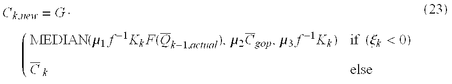
For example, for VBR rate control technique 1, the new targets are derived using the following:
C k , new = G · ( MEDIAN ( μ 1 f - 1 K k F ( Q _ k - 1 , actual ) , μ 2 C _ gop , μ 3 f - 1 K k ) if ( ξ k < 0 ) C _ k else ( 23 )
Figure US06278735-20010821-M00026
As a further example, for VBR rate control technique 2, the new targets are derived using: C k , new = G · ( MEDIAN ( μ 1 r a k C _ gop F ( Q _ k - 1 , actual ) a 2 E k + H ( k ) , μ 2 C _ gop , μ 3 r a k C _ gop a 2 E k + H ( k ) ) if ( ξ k < 0 ) C _ k   else ( 24 )
Figure US06278735-20010821-M00027
where H(k) a1(Ngop *+γk)Nk −1.
The MEDIAN filter is used to compensate for instability conditions (as a result of scene transitions) that may occur in all types of GOP's, e.g., soft or hard. The constant set {μ1, μ2, μ3} enforces a bound on the number of bits produced during a scene transition. In one example, μ1=1.0, μ2=0.9 and μ3=0.9.
The GOP target allocation of equations (23) and (24) can also be used when scene changes are detected. How to detect the scene cut is not described herein, since many techniques of scene change detection are given in the literature. Since the encoding of each GOP starts with an I picture, if the position of this picture is where the scene cut occurs in the sequence, then equation (23) or equation (24) is used to set the new target. Moreover, if the encoder detects a scene change for a P picture, this type of picture is changed to an I type and a new GOP is started and, again, the new target is set according to equation (23) or equation (24).
2.5 ({overscore (C)}-{overscore (Q)}) Instabilities
The (R-Q) relationship of equation (1) is known to work fairly well for a diverse class of video sequences and is a fundamental concept used for many real-time MPEG and non-MPEG compression systems. In accordance with the principles of the present invention, however, this relationship is used to build a causal predictive model to estimate the average bits of a present GOP to be encoded, based on the actual average GOP bits and average quantization factor of previous GOP's. However, this predictive model can become unreliable for some video segments, even when there are no special effects, scene transitions, or scene cuts. The cause of this is related to the non-stationary nature of video sources, e.g., several highly detailed objects moving slowly across a background of significant luminance or chrominance image details, presence of unwanted noise in the scene, etc.
FIG. 9 displays two points derived by an encoder with one being outside of the composite ({overscore (C)}-{overscore (Q)}) curve. This point is a result of the aforementioned criteria and does not obey the ({overscore (C)}-{overscore (Q)}) relationship. Further, it contributes to calculation of a “bad operating point.” The VBR encoder of the present invention suppresses this instability by making an additional contribution to the strategy defined in equation (23) or equation (24). In particular, the GOP bits are set according to the condition below: C k , new = { MAX ( C k , new , G Φ max C _ k , fil ) if ( ξ k < 0 ) ( θ L < Δ Q _ < θ U ) ( C _ k , fil > C _ gop ) MIN ( C k , new , G Φ min C _ k , fil ) elseif ( ξ k < 0 ) ( θ L < Δ Q _ < θ U ) ( C _ k , fil < C _ gop ) G C _ gop   elseif ( ξ k < 0 ) ( θ L < Δ Q _ < θ U ) ( C _ k , fil = C _ gop ) with , ( 25 ) C _ k , fil = ω 1 C _ k - 2 , actual + ω 2 C _ k - 1 , actual ω 1 + ω 2 , ( 26 )
Figure US06278735-20010821-M00028
where ω1 and ω2 represent the weights of the filter. In one example, ω1=1.0 and ω2=1.0, and in another example, ω1 is set to 1.0 and ω2 is set to 3.0.
In the above equation, Φ is a constant used to modulate the number of bits to be allocated. For example, MAX Φ is 1.1 and MIN Φ is 0.9. Thresholds θL (e.g., 0.1) and θU (e.g., 1.0) are chosen under the assumption that a future GOP belongs to the same video segment as the already processed GOP's, and {overscore (C)}k,fil is an average GOP bits, which is determined by applying a linear filter on the bits of the previously encoded GOP's. Output of this linear filter is the new operating point. The MAX and MIN functions are implemented to filter out the encoding bit parameters that result in ({overscore (C)}-{overscore (Q)}) instabilities.
Described in detail above are techniques for providing a real-time single pass variable bit rate encoder that is easy to implement and produces high quality video. An estimate of the number of bits to be allocated to a GOP is determined, and then the estimate is refined using various techniques.
The present invention can be included in an article of manufacture (e.g., one or more computer program products) having, for instance, computer useable media. The media has embodied therein, for instance, computer readable program code means for providing and facilitating the capabilities of the present invention. The article of manufacture can be included as a part of a computer system or sold separately.
Additionally, at least one program storage device readable by a machine, tangibly embodying at least one program of instructions executable by the machine to perform the capabilities of the present invention can be provided.
The flow diagrams depicted herein are just exemplary. There may be many variations to these diagrams or the steps (or operations) described therein without departing from the spirit of the invention. For instance, the steps may be performed in a differing order, or steps may be added, deleted or modified. All of these variations are considered a part of the claimed invention.
Although preferred embodiments have been depicted and described in detail herein, it will be apparent to those skilled in the relevant art that various modifications, additions, substitutions and the like can be made without departing from the spirit of the invention and these are therefore considered to be within the scope of the invention as defined in the following claims.

Claims (29)

What is claimed is:
1. A method of processing groups of frames, said method comprising:
encoding at least one group of frames of an input stream;
determining, prior to encoding the entire input stream, a number of bits to be allocated to another group of frames of said input stream, said another group of frames to be encoded in a self-variable bit rate mode, and wherein said determining uses one or more parameter values obtained from said encoding; and
encoding said another group of frames in a single pass variable bit rate mode, wherein said another group of frames is encoded in only one encoding pass;
wherein said encoding said another group of frames comprises adjusting an ideal number of target bits of a picture type, within said another group of frames, wherein said adjusting comprises scaling a sub-error accumulation of previously encoded groups of frames of said input stream using a first scaling factor and scaling a sub-error accumulation of frames of said another group of frames using a second scaling factor.
2. The method of claim 1, wherein said first scaling factor is smaller than said second scaling factor.
3. A method of processing groups of frames, said method comprising:
encoding at least one group of frames of an input stream; and
determining, prior to encoding the entire input stream, a number of bits to be allocated to another group of frames of said input stream, said another group of frames to be encoded in a self-variable bit rate mode, and wherein said determining uses one or more parameter values obtained from said encoding;
wherein said determining comprises:
modulating, for said another group of frames, a slope of a predefined perceptual function; and
using said modulated slope in a bit rate equation to determine said number of bits.
4. The method of claim 3, wherein said predefined perceptual function comprises:
{overscore (C)} k =f −1 KF({overscore (Q)} k)
wherein F ({overscore (Q)}k)=a1+a2{overscore (Q)}k β in which, a1, a2 and β are constants, {overscore (Q)}k is a quantization factor, and K represents a slope value.
5. The method of claim 3, wherein said bit rate equation comprises: C _ k = ( R k , tot N k P k Z k ) ( ξ k a 1 + η k a 2 ξ k + a 2 ( R k , tot N k P k Z k ) ) ,
Figure US06278735-20010821-M00029
wherein Rk,tot represents a number of remaining bits in a bit budget, Nk represents an adjusted number of groups of frames in an input stream, Pk represents a number of remaining frames of said another group of frames to be encoded, Zk represents a summation of the measures of encoding difficulty, ξk is Δ{overscore (C)}k/Δ{overscore (Q)}k in which {overscore (C)}k is an average bits and {overscore (Q)}k is an average quantization factor, ηk is equal to {overscore (C)}k−1,actualk{overscore (Q)}k−1,actual, and a1 and a2 are constants.
6. A method of processing groups of frames, said method comprising:
encoding at least one group of frames of an input stream; and
determining, prior to encoding the entire input stream, a number of bits to be allocated to another group of frames of said input stream, said another group of frames to be encoded in a self-variable bit rate mode, and wherein said determining uses one or more parameter values obtained from said encoding;
wherein said determining comprises:
determining, for said another group of frames, a translation factor for a predefined perceptual function; and
using said translation factor in a bit rate equation to determine said number of bits.
7. The method of claim 6, wherein said determining said translation factor comprises using: a l k = P k - 1 R k , tot C _ gop - a 2 Y k N k ,
Figure US06278735-20010821-M00030
wherein Pk represents a number of remaining frames of said another group of frames to be encoded, Rk,tot represents a number of remaining bits in a bit budget, {overscore (C)}gop is a rate of said input stream, Yk represents a summation of average quantization factors per group of frames, Nk represents an adjusted number of groups of frames in an input stream, and a2 is a constant.
8. The method of claim 1, wherein said determining comprises compensating for one or more instability conditions of said input stream, wherein said one or more instability conditions comprises at least one or a scene transition, a scene cut and one or more special effects, and wherein said compensating comprises applying a MEDIAN filter to one or more selected attributes of a predefined function used to determine said number of bits.
9. A method of processing groups of frames, said method comprising:
determining a plurality of parameter values from one or more previously encoded group of frames;
computing, for a group of frames to be encoded in a single pass variable bit rate mode, a slope of a predefined function, said computing using one or more of said plurality of parameter values; and
obtaining a bit rate for said group of frames to be encoded using said computed slope and one or more of said plurality of parameter values.
10. The method of claim 9, further comprising encoding said group of frames to be encoded in said variable bit rate mode at said bit rate obtained for said group of frames to be encoded.
11. The method of claim 10, further comprising repeating said determining, computing, obtaining and encoding for other groups of frames of said input stream.
12. The method of claim 11, wherein said determining, for each group of frames to be encoded, comprises using data from the last two groups of encoded frames.
13. The method of claim 9, wherein said computing said slope comprises using the following function: K k = f R k , tot N k P k Z k ,
Figure US06278735-20010821-M00031
wherein f is a frame rate of said input stream, Rk,tot is a remaining number of bits in a bit budget, Nk represents an adjusted number of groups of frames in an input stream, Pk represents a number of remaining frames of said another group of frames to be encoded and Zk represents a summation of the measures of encoding difficulty.
14. The method of claim 9, wherein said obtaining comprises using a predefined function to obtain said bit rate.
15. The method of claim 14, wherein said predefined function comprises: C _ k = ( R k , tot N k P k Z k ) ( ξ k a 1 + η k a 2 ξ k + a 2 ( R k , tot N k P k Z k ) ) ,
Figure US06278735-20010821-M00032
wherein Rk,tot represents a number of remaining bits in a bit budget, Nk represents an adjusted number of groups of frames in an input stream, Pk represents a number of remaining frames of said another group of frames to be encoded, Zk represents a summation of the measures of encoding difficulty, ξk is Δ{overscore (C)}k/Δ{overscore (Q)}k in which {overscore (C)}k is an average bits and {overscore (Q)}k is an average quantization factor, ωk is equal to {overscore (C)}k−1,actualk{overscore (Q)}k−1,actual, and a1 and a2 are constants.
16. The method of claim 14, wherein said predefined function represents an instantaneous rate-quantization behavior of said another group of frames and a perceptual model indicating a complexity of said another group of frames.
17. The method of claim 16, wherein said rate-quantization behavior is defined by:
{overscore (C)}k=−ξk{overscore (Q)}kηk,
wherein {overscore (C)}k is an average bits, {overscore (Q)}k is an average quantization scaler, ξk is equal to Δ{overscore (C)}k/Δ{overscore (Q)}k in which Δ{overscore (C)}k={overscore (C)}k−1,actual−{overscore (C)}k−2,actual, and Δ{overscore (Q)}k={overscore (Q)}k−2,actual−{overscore (Q)}k−1,actual, and ηk={overscore (C)}k−1,actualk{overscore (Q)}k−1,actual.
18. The method of claim 16, wherein said perceptual model is defined by:
{overscore (C)} k =f −1 KF({overscore (Q)} k)
wherein F ({overscore (Q)}k)=a1+a2{overscore (Q)}k μ in which, a1, a2 and β are constants, {overscore (Q)}k is a quantization factor, and K represents a slope value.
19. The method of claim 9, wherein said determining comprises compensating for one or more instability conditions of said input stream.
20. A single pass self-variable bit rate encoder comprising:
an encoding engine adapted to encode at least one group of frames of an input stream; and
means for determining, prior to encoding the entire input stream, a number of bits to be allocated to another group of frames of said input stream, said another group of frames to be encoded in a self-variable bit rate mode, and wherein said means for determining uses one or more parameter values obtained from encoding said at least one group of frames,
wherein said means for determining comprises:
means for modulating, for said another group of frames, a slope of a predefined perceptual function; and
means for using said modulated slope in a bit rate equation to determine said number of bits.
21. A single pass self-variable bit rate encoder comprising:
an encoding engine adapted to encode at least one group of frames of an input stream; and
means for determining prior to encoding the entire input stream, a number of bits to be allocated to another group of frames of said input stream, said another group of frames to be encoded in a self-variable bit rate mode, and wherein said means for determining uses one or more parameter values obtained from encoding said at least one group of frames,
wherein said means for determining comprises:
means for determining, for said another group of frames, a translation factor for a predefined perceptual function; and
means for using said translation factor in a bit rate equation to determine said number of bits.
22. The encoder of claim 21 wherein said means for determining comprises means for compensating for one or more instability conditions of said input stream, wherein said one or more instability conditions comprises at least one of a scene transition, a scene cut and one or more special effects, and wherein said means for compensating comprises means for applying a MEDIAN filter to one or more selected attributes of a predefined function used to determine said number of bits.
23. A single pass variable bit rate encoder comprising:
means for determining a plurality of parameter values from one or more previously encoded group of frames;
means for computing, for a group of frames to be encoded in a single pass variable bit rate mode, a slope of a predefined function, said computing using one or more of said plurality of parameter values; and
means for obtaining a bit rate for said group of frames to be encoded using said computed slope and one or more of said plurality of parameter values.
24. The encoder of claim 23, further comprising means for encoding said group of frames to be encoded in a variable bit rate mode at said bit rate obtained for said group of frames to be encoded.
25. The encoder of claim 23, wherein said means for obtaining comprises means for using a predefined function to obtain said bit rate.
26. The encoder of claim 25, wherein said predefined function represents an instantaneous rate-quantization behavior of said another group of frames and a perceptual model indicating a complexity of said another group of frames.
27. The encoder of claim 23, wherein said means for determining comprises means for compensating for one or more instability conditions of said input stream.
28. An article of manufacture, comprising:
at least one computer usable medium having computer readable program code means embodied therein for causing the processing of groups of frames, the computer readable program code means in said article of manufacture comprising:
computer readable program code means for causing a computer to encode at least one group of frames of an input stream; and
computer readable program code means for causing a computer to determine, prior to encoding the entire input stream, a number of bits to be allocated to another group of frames of said input stream, said another group of frames to be encoded in a self-variable bit rate mode, and wherein said computer readable program code means for causing a computer to determine uses one or more parameter values obtained from said encoding;
wherein said computer readable program code means for causing a computer to determine comprises:
computer readable program code means for causing a computer to modulate, for said another group of frames, a slope of a predefined perceptual function; and
computer readable program code means for causing a computer to use said modulated slope in a bit rate equation to determine said number of bits.
29. An article of manufacture, comprising:
at least one computer usable medium having computer readable program code means embodied therein for causing the processing of groups of frames, the computer readable program code means in said article of manufacture comprising:
computer readable program code means for causing a computer to encode at least one group of frames of an input stream; and
computer readable program code means for causing a computer to determine, prior to encoding the entire input stream, a number of bits to be allocated to another group of frames of said input stream, said another group of frames to be encoded in a self-variable bit rate mode, and wherein said computer readable program code means for causing a computer to determine uses one or more parameter values obtained from said encoding;
wherein said computer readable program code means for causing a computer to determine comprises:
computer readable program code means for causing a computer to determine, for said another group of frames, a translation factor for a predefined perceptual function; and
computer readable program code means for causing a computer to use said translation factor in a bit rate equation to determine said number of bits.
US09/044,642 1998-03-19 1998-03-19 Real-time single pass variable bit rate control strategy and encoder Expired - Fee Related US6278735B1 (en)

Priority Applications (5)

Application Number Priority Date Filing Date Title
US09/044,642 US6278735B1 (en) 1998-03-19 1998-03-19 Real-time single pass variable bit rate control strategy and encoder
TW087110219A TW404132B (en) 1998-03-19 1998-06-25 A real-time single pass variable bit rate control strategy and encoder
KR1019990005614A KR100305941B1 (en) 1998-03-19 1999-02-19 A real-time single pass variable bit rate control strategy and encoder
SG9901279A SG80615A1 (en) 1998-03-19 1999-02-27 A real time single pass variable bit rate control strategy and encoder
JP11063139A JPH11346362A (en) 1998-03-19 1999-03-10 Real time single path variable bit rate control method, and encoder

Applications Claiming Priority (1)

Application Number Priority Date Filing Date Title
US09/044,642 US6278735B1 (en) 1998-03-19 1998-03-19 Real-time single pass variable bit rate control strategy and encoder

Publications (1)

Publication Number Publication Date
US6278735B1 true US6278735B1 (en) 2001-08-21

Family

ID=21933502

Family Applications (1)

Application Number Title Priority Date Filing Date
US09/044,642 Expired - Fee Related US6278735B1 (en) 1998-03-19 1998-03-19 Real-time single pass variable bit rate control strategy and encoder

Country Status (5)

Country Link
US (1) US6278735B1 (en)
JP (1) JPH11346362A (en)
KR (1) KR100305941B1 (en)
SG (1) SG80615A1 (en)
TW (1) TW404132B (en)

Cited By (107)

* Cited by examiner, † Cited by third party
Publication number Priority date Publication date Assignee Title
US20020021756A1 (en) * 2000-07-11 2002-02-21 Mediaflow, Llc. Video compression using adaptive selection of groups of frames, adaptive bit allocation, and adaptive replenishment
US20020034246A1 (en) * 2000-08-04 2002-03-21 Kohji Yamada Method and apparatus for image signal encoding
US20020047932A1 (en) * 2000-04-05 2002-04-25 Snell & Wilcox Limited Spatial video processing
US6453424B1 (en) * 1999-03-31 2002-09-17 International Business Machines Corporation System and method for temporally controlling instruction execution
US20020143556A1 (en) * 2001-01-26 2002-10-03 Kadatch Andrew V. Quantization loop with heuristic approach
US20020186890A1 (en) * 2001-05-03 2002-12-12 Ming-Chieh Lee Dynamic filtering for lossy compression
US20020190888A1 (en) * 2000-12-11 2002-12-19 Ikuo Tsukagoshi System and method for overrun catch-up in a real-time software
US20030021344A1 (en) * 2001-07-27 2003-01-30 General Instrument Corporation Methods and apparatus for sub-pixel motion estimation
US6535555B1 (en) * 1999-04-26 2003-03-18 Thomson Licensing S.A. Quantizing method and device for video compression
US20030053698A1 (en) * 2001-09-18 2003-03-20 Ferguson Kevin M. Temporal processing for realtime human vision system behavior modeling
US20030084182A1 (en) * 2001-10-25 2003-05-01 Alcatel Method of transmitting packets via a telecommunications network using IP protocol
US20030095594A1 (en) * 2001-11-21 2003-05-22 Indra Laksono Method and system for rate control during video transcoding
FR2832582A1 (en) * 2001-11-21 2003-05-23 Canon Kk Multimedia data coding process for domestic networks selects parameters using quality assessment
US20030147466A1 (en) * 2002-02-01 2003-08-07 Qilian Liang Method, system, device and computer program product for MPEG variable bit rate (VBR) video traffic classification using a nearest neighbor classifier
US20030152148A1 (en) * 2001-11-21 2003-08-14 Indra Laksono System and method for multiple channel video transcoding
US20030202604A1 (en) * 1998-01-22 2003-10-30 British Broadcasting Corporation Video processing system also compressing coding decision data
US20030206583A1 (en) * 2002-05-03 2003-11-06 Microsoft Corporation Signaling for fading compensation
US20030210821A1 (en) * 2001-04-20 2003-11-13 Front Porch Digital Inc. Methods and apparatus for generating, including and using information relating to archived audio/video data
US6661926B1 (en) * 1999-06-18 2003-12-09 Thomson Licensing S.A. Picture compression process, especially of the MPEG2 type
US20030229902A1 (en) * 2002-06-10 2003-12-11 Shankar Moni Dynamic rate control
US20030235250A1 (en) * 2002-06-24 2003-12-25 Ankur Varma Video deblocking
US20040001638A1 (en) * 2002-06-28 2004-01-01 Microsoft Corporation Rate allocation for mixed content video
US6700623B1 (en) 1998-12-10 2004-03-02 Snell & Wilcox Limited Video signal processing using triplets of pixels
US20040057465A1 (en) * 2002-09-24 2004-03-25 Koninklijke Philips Electronics N.V. Flexible data partitioning and packetization for H.26L for improved packet loss resilience
US6741648B2 (en) * 2000-11-10 2004-05-25 Nokia Corporation Apparatus, and associated method, for selecting an encoding rate by which to encode video frames of a video sequence
US6760379B1 (en) 1998-03-06 2004-07-06 British Broadcasting Corporation Cascading of up conversion and down conversion
US20040161033A1 (en) * 2003-02-19 2004-08-19 Youji Notoya Moving picture coding method and moving picture decoding method
US20040184529A1 (en) * 2003-02-14 2004-09-23 Canon Europa N.V. Method and device for analyzing video sequences in a communication network
US6845107B1 (en) * 1997-10-15 2005-01-18 Sony Corporation Video data multiplexer, video data multiplexing control method, method and apparatus for multiplexing encoded stream, and encoding method and apparatus
US20050013500A1 (en) * 2003-07-18 2005-01-20 Microsoft Corporation Intelligent differential quantization of video coding
US20050015259A1 (en) * 2003-07-18 2005-01-20 Microsoft Corporation Constant bitrate media encoding techniques
US20050015246A1 (en) * 2003-07-18 2005-01-20 Microsoft Corporation Multi-pass variable bitrate media encoding
US20050036699A1 (en) * 2003-07-18 2005-02-17 Microsoft Corporation Adaptive multiple quantization
US6865224B1 (en) * 1999-01-28 2005-03-08 Snell & Wilcox Limited Bit rate control for video data compression
US20050053155A1 (en) * 2003-09-07 2005-03-10 Microsoft Corporation Intensity estimation/compensation for interlaced forward-predicted fields
US6895049B1 (en) 1998-10-09 2005-05-17 Snell & Wilcox Limited Analysis of compression decoded video image sequences
US6898321B1 (en) 1998-10-09 2005-05-24 Snell & Wilcox Limited Method and apparatus for blocking effect reduction
US20050143993A1 (en) * 2001-12-14 2005-06-30 Microsoft Corporation Quality and rate control strategy for digital audio
US6922214B1 (en) 1998-11-03 2005-07-26 Snell & Wilcox Limited Video signal processing
US20050196050A1 (en) * 2004-03-08 2005-09-08 Canon Kabushiki Kaisha Method and device for access to a digital image stored on a server computer
US20050238096A1 (en) * 2003-07-18 2005-10-27 Microsoft Corporation Fractional quantization step sizes for high bit rates
US20050286631A1 (en) * 2004-06-27 2005-12-29 Hsi Jung Wu Encoding with visual masking
US20060013298A1 (en) * 2004-06-27 2006-01-19 Xin Tong Multi-pass video encoding
US20060034375A1 (en) * 1998-10-09 2006-02-16 Snell & Wilcox Limited Data compression unit control for alignment of output signal
US20060062292A1 (en) * 2004-09-23 2006-03-23 International Business Machines Corporation Single pass variable bit rate control strategy and encoder for processing a video frame of a sequence of video frames
US20060165168A1 (en) * 2003-06-26 2006-07-27 Boyce Jill M Multipass video rate control to match sliding window channel constraints
WO2006099086A1 (en) * 2005-03-10 2006-09-21 Qualcomm Incorporated Context-adaptive bandwidth adjustment in video rate control
US20060224762A1 (en) * 2005-03-10 2006-10-05 Qualcomm Incorporated Quasi-constant-quality rate control with look-ahead
US20060245492A1 (en) * 2005-04-28 2006-11-02 Thomas Pun Single pass rate controller
US7161635B1 (en) 1998-05-15 2007-01-09 Snell & Wilcox Limited Video signal processing
US20070116116A1 (en) * 1999-09-27 2007-05-24 Bernd Sostawa Digital transcoding system
US20070127579A1 (en) * 2003-01-08 2007-06-07 Adriana Dumitras Method and apparatus for improved coding mode selection
US20070177808A1 (en) * 2006-01-31 2007-08-02 Canon Kabushiki Kaisha Image processing apparatus
US20080037657A1 (en) * 2002-05-03 2008-02-14 Microsoft Corporation Parameterization for fading compensation
US7477691B1 (en) 1998-01-22 2009-01-13 Snell & Wilcox Limited Video signal compression
US20090180555A1 (en) * 2008-01-10 2009-07-16 Microsoft Corporation Filtering and dithering as pre-processing before encoding
US20100008428A1 (en) * 2004-05-21 2010-01-14 Stephen Gordon Multistandard video recorder
US20100111163A1 (en) * 2006-09-28 2010-05-06 Hua Yang Method for p-domain frame level bit allocation for effective rate control and enhanced video encoding quality
US7738554B2 (en) 2003-07-18 2010-06-15 Microsoft Corporation DC coefficient signaling at small quantization step sizes
US20100223396A1 (en) * 2009-02-27 2010-09-02 Yahoo! Inc. Intelligent status polling
US7801383B2 (en) 2004-05-15 2010-09-21 Microsoft Corporation Embedded scalar quantizers with arbitrary dead-zone ratios
US7925774B2 (en) 2008-05-30 2011-04-12 Microsoft Corporation Media streaming using an index file
US7974340B2 (en) 2006-04-07 2011-07-05 Microsoft Corporation Adaptive B-picture quantization control
US7995649B2 (en) 2006-04-07 2011-08-09 Microsoft Corporation Quantization adjustment based on texture level
US20110222604A1 (en) * 2008-11-13 2011-09-15 Thomson Licensing Multiple thread video encoding using gop merging and bit allocation
CN102223531A (en) * 2010-04-14 2011-10-19 新港传播媒介公司 Fixed buffer real-time image compression technique
EP2382784A2 (en) * 2009-01-29 2011-11-02 Microsoft Corporation Multiple bit rate video encoding using variable bit rate and dynamic resolution for adaptive video streaming
US8059721B2 (en) 2006-04-07 2011-11-15 Microsoft Corporation Estimating sample-domain distortion in the transform domain with rounding compensation
US8130828B2 (en) 2006-04-07 2012-03-06 Microsoft Corporation Adjusting quantization to preserve non-zero AC coefficients
US8160132B2 (en) 2008-02-15 2012-04-17 Microsoft Corporation Reducing key picture popping effects in video
US8184694B2 (en) 2006-05-05 2012-05-22 Microsoft Corporation Harmonic quantizer scale
US8189933B2 (en) 2008-03-31 2012-05-29 Microsoft Corporation Classifying and controlling encoding quality for textured, dark smooth and smooth video content
US8189666B2 (en) 2009-02-02 2012-05-29 Microsoft Corporation Local picture identifier and computation of co-located information
EP2472868A1 (en) * 2010-12-29 2012-07-04 British Telecommunications Public Limited Company Video coding
US8238424B2 (en) 2007-02-09 2012-08-07 Microsoft Corporation Complexity-based adaptive preprocessing for multiple-pass video compression
US8243797B2 (en) 2007-03-30 2012-08-14 Microsoft Corporation Regions of interest for quality adjustments
US8254455B2 (en) 2007-06-30 2012-08-28 Microsoft Corporation Computing collocated macroblock information for direct mode macroblocks
US20120219054A1 (en) * 2011-02-24 2012-08-30 Vixs Systems, Inc. Multi-pass video encoder and methods for use therewith
US8265140B2 (en) 2008-09-30 2012-09-11 Microsoft Corporation Fine-grained client-side control of scalable media delivery
US20120243613A9 (en) * 2005-01-26 2012-09-27 Nader Mohsenian Systems, methods, and apparatus for real-time video encoding
US20120269272A1 (en) * 2009-10-29 2012-10-25 Thomas Sikora Method and device for processing a video sequence
US8325800B2 (en) 2008-05-07 2012-12-04 Microsoft Corporation Encoding streaming media as a high bit rate layer, a low bit rate layer, and one or more intermediate bit rate layers
US8331438B2 (en) 2007-06-05 2012-12-11 Microsoft Corporation Adaptive selection of picture-level quantization parameters for predicted video pictures
US8355436B2 (en) 2002-11-08 2013-01-15 Apple Inc. Method and apparatus for control of rate-distortion tradeoff by mode selection in video encoders
US20130016784A1 (en) * 2011-07-14 2013-01-17 Technische Universitat Berlin Method and device for processing pixels contained in a video sequence
US8379851B2 (en) 2008-05-12 2013-02-19 Microsoft Corporation Optimized client side rate control and indexed file layout for streaming media
US8422546B2 (en) 2005-05-25 2013-04-16 Microsoft Corporation Adaptive video encoding using a perceptual model
US8442337B2 (en) 2007-04-18 2013-05-14 Microsoft Corporation Encoding adjustments for animation content
US8498335B2 (en) 2007-03-26 2013-07-30 Microsoft Corporation Adaptive deadzone size adjustment in quantization
US8503536B2 (en) 2006-04-07 2013-08-06 Microsoft Corporation Quantization adjustments for DC shift artifacts
US20130279882A1 (en) * 2012-04-23 2013-10-24 Apple Inc. Coding of Video and Audio with Initialization Fragments
US8705616B2 (en) 2010-06-11 2014-04-22 Microsoft Corporation Parallel multiple bitrate video encoding to reduce latency and dependences between groups of pictures
US8897359B2 (en) 2008-06-03 2014-11-25 Microsoft Corporation Adaptive quantization for enhancement layer video coding
US9268723B2 (en) 2011-12-21 2016-02-23 Intel Corporation Dram compression scheme to reduce power consumption in motion compensation and display refresh
CN106257402A (en) * 2015-06-19 2016-12-28 Hgst荷兰公司 The equipment detected for the single pass entropy transmitted for data and method
US9571856B2 (en) 2008-08-25 2017-02-14 Microsoft Technology Licensing, Llc Conversion operations in scalable video encoding and decoding
US9591318B2 (en) 2011-09-16 2017-03-07 Microsoft Technology Licensing, Llc Multi-layer encoding and decoding
US20180324427A1 (en) * 2017-05-04 2018-11-08 Sony Corporation Quantization partitioning for enhanced image compression
US10152389B2 (en) 2015-06-19 2018-12-11 Western Digital Technologies, Inc. Apparatus and method for inline compression and deduplication
US10523940B2 (en) * 2017-03-14 2019-12-31 Axis Ab Method and encoder system for determining GOP length for encoding video
US10531087B2 (en) * 2015-08-03 2020-01-07 Canon Kabushiki Kaisha Image processing apparatus, imaging apparatus, and image processing method
CN110708547A (en) * 2018-07-10 2020-01-17 三星显示有限公司 Efficient entropy coding group grouping method for transform mode
US10554985B2 (en) 2003-07-18 2020-02-04 Microsoft Technology Licensing, Llc DC coefficient signaling at small quantization step sizes
US10863179B1 (en) * 2018-09-05 2020-12-08 Amazon Technologies, Inc. Overlapped rate control for high-quality segmented video encoding
US11089343B2 (en) 2012-01-11 2021-08-10 Microsoft Technology Licensing, Llc Capability advertisement, configuration and control for video coding and decoding
TWI806707B (en) * 2022-07-13 2023-06-21 緯創資通股份有限公司 Communication method and communication device thereof
CN110708547B (en) * 2018-07-10 2024-04-09 三星显示有限公司 Efficient entropy coding group grouping method for transform modes

Families Citing this family (7)

* Cited by examiner, † Cited by third party
Publication number Priority date Publication date Assignee Title
KR100394014B1 (en) * 2001-06-23 2003-08-09 엘지전자 주식회사 Apparatus for transcoding video
KR100848457B1 (en) * 2002-05-06 2008-07-28 주식회사 케이티 Method of restricting bit generation and preventing buffer overflow in video encoder
US7535959B2 (en) 2003-10-16 2009-05-19 Nvidia Corporation Apparatus, system, and method for video encoder rate control
JP4988567B2 (en) * 2004-06-27 2012-08-01 アップル インコーポレイテッド Multi-pass video encoding
US7974193B2 (en) 2005-04-08 2011-07-05 Qualcomm Incorporated Methods and systems for resizing multimedia content based on quality and rate information
US8582905B2 (en) 2006-01-31 2013-11-12 Qualcomm Incorporated Methods and systems for rate control within an encoding device
CN103517080A (en) * 2012-06-21 2014-01-15 北京数码视讯科技股份有限公司 Real-time video stream encoder and real-time video stream encoding method

Citations (30)

* Cited by examiner, † Cited by third party
Publication number Priority date Publication date Assignee Title
US5134476A (en) * 1990-03-30 1992-07-28 At&T Bell Laboratories Video signal encoding with bit rate control
US5231484A (en) 1991-11-08 1993-07-27 International Business Machines Corporation Motion video compression system with adaptive bit allocation and quantization
US5241383A (en) 1992-05-13 1993-08-31 Bell Communications Research, Inc. Pseudo-constant bit rate video coding with quantization parameter adjustment
US5426463A (en) 1993-02-22 1995-06-20 Rca Thomson Licensing Corporation Apparatus for controlling quantizing in a video signal compressor
EP0664651A2 (en) 1994-01-21 1995-07-26 Hitachi, Ltd. Video communication system, with variable and fixed bit-rate storage equipment
US5539469A (en) * 1994-12-30 1996-07-23 Daewoo Electronics Co., Ltd. Apparatus for determining motion vectors through the use of an adaptive median filtering technique
US5566208A (en) 1994-03-17 1996-10-15 Philips Electronics North America Corp. Encoder buffer having an effective size which varies automatically with the channel bit-rate
EP0753831A1 (en) 1995-07-10 1997-01-15 France Telecom Modified leaky-bucket method
JPH0937242A (en) 1995-07-21 1997-02-07 Nippon Telegr & Teleph Corp <Ntt> Variable bit rate image signal coder
US5606369A (en) 1994-12-28 1997-02-25 U.S. Philips Corporation Buffering for digital video signal encoders using joint bit-rate control
JPH0970041A (en) 1995-08-30 1997-03-11 Kokusai Denshin Denwa Co Ltd <Kdd> Variable bit rate coder
JPH0993537A (en) 1995-09-27 1997-04-04 Mitsubishi Electric Corp Digital video signal recording and reproducing device and digital video signal coding method
US5631644A (en) * 1993-12-22 1997-05-20 Sharp Kabushiki Kaisha Image encoding apparatus
JPH09186999A (en) 1995-12-27 1997-07-15 Lg Electron Inc Digital moving image compressor
WO1997032436A1 (en) 1996-03-02 1997-09-04 Deutsche Thomson-Brandt Gmbh Method and apparatus for encoding or decoding digital video data
US5675384A (en) 1995-10-03 1997-10-07 Nec Usa, Inc. VBR MPEG video encoding for ATM networks with dynamic bandwidth renegotiation
US5680483A (en) * 1994-03-02 1997-10-21 U.S. Philips Corporation Method and device for coding digital signals which are representative of a sequence of pictures
US5682204A (en) 1995-12-26 1997-10-28 C Cube Microsystems, Inc. Video encoder which uses intra-coding when an activity level of a current macro-block is smaller than a threshold level
WO1997043859A1 (en) 1996-05-09 1997-11-20 Thomson Multimedia Variable bit-rate encoder
US5703889A (en) 1991-06-04 1997-12-30 Kabushiki Kaisha Toshiba High efficiency coding signal processing apparatus with error propagation influence reduction
US5703646A (en) 1993-04-09 1997-12-30 Sony Corporation Picture encoding method, picture encoding apparatus and picture recording medium
US5715176A (en) 1996-01-23 1998-02-03 International Business Machines Corporation Method and system for locating a frame position in an MPEG data stream
US5748243A (en) * 1993-11-08 1998-05-05 Sony Corporation Method for encoding and decoding motion picture as a function of its non-linear characteristic
US5754233A (en) * 1995-09-04 1998-05-19 Sony Corporation Compression encoding apparatus and recording apparatus for compressionencoded data
US5764698A (en) * 1993-12-30 1998-06-09 International Business Machines Corporation Method and apparatus for efficient compression of high quality digital audio
US5764805A (en) * 1995-10-25 1998-06-09 David Sarnoff Research Center, Inc. Low bit rate video encoder using overlapping block motion compensation and zerotree wavelet coding
US5874995A (en) * 1994-10-28 1999-02-23 Matsuhita Electric Corporation Of America MPEG video decoder having a high bandwidth memory for use in decoding interlaced and progressive signals
US5877814A (en) * 1994-04-20 1999-03-02 Thomson Consumer Electronics, Inc. Asynchronous control signal generating apparatus
US5956426A (en) * 1994-05-25 1999-09-21 Sony Corporation Multi-coding apparatus
US5987179A (en) * 1997-09-05 1999-11-16 Eastman Kodak Company Method and apparatus for encoding high-fidelity still images in MPEG bitstreams

Patent Citations (30)

* Cited by examiner, † Cited by third party
Publication number Priority date Publication date Assignee Title
US5134476A (en) * 1990-03-30 1992-07-28 At&T Bell Laboratories Video signal encoding with bit rate control
US5703889A (en) 1991-06-04 1997-12-30 Kabushiki Kaisha Toshiba High efficiency coding signal processing apparatus with error propagation influence reduction
US5231484A (en) 1991-11-08 1993-07-27 International Business Machines Corporation Motion video compression system with adaptive bit allocation and quantization
US5241383A (en) 1992-05-13 1993-08-31 Bell Communications Research, Inc. Pseudo-constant bit rate video coding with quantization parameter adjustment
US5426463A (en) 1993-02-22 1995-06-20 Rca Thomson Licensing Corporation Apparatus for controlling quantizing in a video signal compressor
US5703646A (en) 1993-04-09 1997-12-30 Sony Corporation Picture encoding method, picture encoding apparatus and picture recording medium
US5748243A (en) * 1993-11-08 1998-05-05 Sony Corporation Method for encoding and decoding motion picture as a function of its non-linear characteristic
US5631644A (en) * 1993-12-22 1997-05-20 Sharp Kabushiki Kaisha Image encoding apparatus
US5764698A (en) * 1993-12-30 1998-06-09 International Business Machines Corporation Method and apparatus for efficient compression of high quality digital audio
EP0664651A2 (en) 1994-01-21 1995-07-26 Hitachi, Ltd. Video communication system, with variable and fixed bit-rate storage equipment
US5680483A (en) * 1994-03-02 1997-10-21 U.S. Philips Corporation Method and device for coding digital signals which are representative of a sequence of pictures
US5566208A (en) 1994-03-17 1996-10-15 Philips Electronics North America Corp. Encoder buffer having an effective size which varies automatically with the channel bit-rate
US5877814A (en) * 1994-04-20 1999-03-02 Thomson Consumer Electronics, Inc. Asynchronous control signal generating apparatus
US5956426A (en) * 1994-05-25 1999-09-21 Sony Corporation Multi-coding apparatus
US5874995A (en) * 1994-10-28 1999-02-23 Matsuhita Electric Corporation Of America MPEG video decoder having a high bandwidth memory for use in decoding interlaced and progressive signals
US5606369A (en) 1994-12-28 1997-02-25 U.S. Philips Corporation Buffering for digital video signal encoders using joint bit-rate control
US5539469A (en) * 1994-12-30 1996-07-23 Daewoo Electronics Co., Ltd. Apparatus for determining motion vectors through the use of an adaptive median filtering technique
EP0753831A1 (en) 1995-07-10 1997-01-15 France Telecom Modified leaky-bucket method
JPH0937242A (en) 1995-07-21 1997-02-07 Nippon Telegr & Teleph Corp <Ntt> Variable bit rate image signal coder
JPH0970041A (en) 1995-08-30 1997-03-11 Kokusai Denshin Denwa Co Ltd <Kdd> Variable bit rate coder
US5754233A (en) * 1995-09-04 1998-05-19 Sony Corporation Compression encoding apparatus and recording apparatus for compressionencoded data
JPH0993537A (en) 1995-09-27 1997-04-04 Mitsubishi Electric Corp Digital video signal recording and reproducing device and digital video signal coding method
US5675384A (en) 1995-10-03 1997-10-07 Nec Usa, Inc. VBR MPEG video encoding for ATM networks with dynamic bandwidth renegotiation
US5764805A (en) * 1995-10-25 1998-06-09 David Sarnoff Research Center, Inc. Low bit rate video encoder using overlapping block motion compensation and zerotree wavelet coding
US5682204A (en) 1995-12-26 1997-10-28 C Cube Microsystems, Inc. Video encoder which uses intra-coding when an activity level of a current macro-block is smaller than a threshold level
JPH09186999A (en) 1995-12-27 1997-07-15 Lg Electron Inc Digital moving image compressor
US5715176A (en) 1996-01-23 1998-02-03 International Business Machines Corporation Method and system for locating a frame position in an MPEG data stream
WO1997032436A1 (en) 1996-03-02 1997-09-04 Deutsche Thomson-Brandt Gmbh Method and apparatus for encoding or decoding digital video data
WO1997043859A1 (en) 1996-05-09 1997-11-20 Thomson Multimedia Variable bit-rate encoder
US5987179A (en) * 1997-09-05 1999-11-16 Eastman Kodak Company Method and apparatus for encoding high-fidelity still images in MPEG bitstreams

Non-Patent Citations (5)

* Cited by examiner, † Cited by third party
Title
"Controlling The Trade-Off Between Reserved Bandwidth And Delay For Variable Bit Rate Multimedia Streams," IBM Technical Disclosure Bulletin, vol. 37, No. 11, pp. 127-130 (Nov. 1994).
"Video Sub-Band Coder," IBM Technical Disclosure Bulletin, vol. 34, No. 7A, pp. 191-192 (Dec. 1991).
Interface 23 [7], pp. 126-129, Jul. 1997. (Translation).
O. Verscheure, et al., "Perceptual Bit Allocation For MPEG-2 CBR Video Coding," Proceedings, International Conference on Image Processing, vol. 1, pp. 117-120, 1996 (IEEE).*
Satoshi Kondo, "An Algorithm of MPEG2 Realtime Variable Bit Rate Video Coding," Technical Report of Television Society, 20 [68], pp. 45-52, Dec. 13, 1996. (Abstract).

Cited By (217)

* Cited by examiner, † Cited by third party
Publication number Priority date Publication date Assignee Title
US6845107B1 (en) * 1997-10-15 2005-01-18 Sony Corporation Video data multiplexer, video data multiplexing control method, method and apparatus for multiplexing encoded stream, and encoding method and apparatus
US7123657B2 (en) 1998-01-22 2006-10-17 British Broadcasting Corporation Video processing system also compressing coding decision data
US7477691B1 (en) 1998-01-22 2009-01-13 Snell & Wilcox Limited Video signal compression
US20030202604A1 (en) * 1998-01-22 2003-10-30 British Broadcasting Corporation Video processing system also compressing coding decision data
US6760379B1 (en) 1998-03-06 2004-07-06 British Broadcasting Corporation Cascading of up conversion and down conversion
US7161635B1 (en) 1998-05-15 2007-01-09 Snell & Wilcox Limited Video signal processing
US6895049B1 (en) 1998-10-09 2005-05-17 Snell & Wilcox Limited Analysis of compression decoded video image sequences
US6898321B1 (en) 1998-10-09 2005-05-24 Snell & Wilcox Limited Method and apparatus for blocking effect reduction
US20060034375A1 (en) * 1998-10-09 2006-02-16 Snell & Wilcox Limited Data compression unit control for alignment of output signal
US7023925B1 (en) 1998-10-09 2006-04-04 Snell & Wilcox Limited Data compression unit control for alignment of output signal
US6922214B1 (en) 1998-11-03 2005-07-26 Snell & Wilcox Limited Video signal processing
US6700623B1 (en) 1998-12-10 2004-03-02 Snell & Wilcox Limited Video signal processing using triplets of pixels
US6865224B1 (en) * 1999-01-28 2005-03-08 Snell & Wilcox Limited Bit rate control for video data compression
US6453424B1 (en) * 1999-03-31 2002-09-17 International Business Machines Corporation System and method for temporally controlling instruction execution
US6535555B1 (en) * 1999-04-26 2003-03-18 Thomson Licensing S.A. Quantizing method and device for video compression
US6661926B1 (en) * 1999-06-18 2003-12-09 Thomson Licensing S.A. Picture compression process, especially of the MPEG2 type
US7936816B2 (en) 1999-09-27 2011-05-03 Harman Becker Automotive Systems Gmbh Digital transcoding system
US20070116116A1 (en) * 1999-09-27 2007-05-24 Bernd Sostawa Digital transcoding system
US6950560B2 (en) 2000-04-05 2005-09-27 Snell & Wilcox Limited Spatial video processing
US20020047932A1 (en) * 2000-04-05 2002-04-25 Snell & Wilcox Limited Spatial video processing
US20020021756A1 (en) * 2000-07-11 2002-02-21 Mediaflow, Llc. Video compression using adaptive selection of groups of frames, adaptive bit allocation, and adaptive replenishment
US6801572B2 (en) * 2000-08-04 2004-10-05 Fujitsu Limited Method and apparatus for image signal encoding
US20020034246A1 (en) * 2000-08-04 2002-03-21 Kohji Yamada Method and apparatus for image signal encoding
US6741648B2 (en) * 2000-11-10 2004-05-25 Nokia Corporation Apparatus, and associated method, for selecting an encoding rate by which to encode video frames of a video sequence
US20020190888A1 (en) * 2000-12-11 2002-12-19 Ikuo Tsukagoshi System and method for overrun catch-up in a real-time software
US6990144B2 (en) * 2000-12-11 2006-01-24 Sony Corporation System and method for overrun catch-up in a real-time software
US7062445B2 (en) 2001-01-26 2006-06-13 Microsoft Corporation Quantization loop with heuristic approach
US20020143556A1 (en) * 2001-01-26 2002-10-03 Kadatch Andrew V. Quantization loop with heuristic approach
US6947598B2 (en) * 2001-04-20 2005-09-20 Front Porch Digital Inc. Methods and apparatus for generating, including and using information relating to archived audio/video data
US20030210821A1 (en) * 2001-04-20 2003-11-13 Front Porch Digital Inc. Methods and apparatus for generating, including and using information relating to archived audio/video data
US7206453B2 (en) 2001-05-03 2007-04-17 Microsoft Corporation Dynamic filtering for lossy compression
US20020186890A1 (en) * 2001-05-03 2002-12-12 Ming-Chieh Lee Dynamic filtering for lossy compression
US6859494B2 (en) * 2001-07-27 2005-02-22 General Instrument Corporation Methods and apparatus for sub-pixel motion estimation
US20030021344A1 (en) * 2001-07-27 2003-01-30 General Instrument Corporation Methods and apparatus for sub-pixel motion estimation
US20030053698A1 (en) * 2001-09-18 2003-03-20 Ferguson Kevin M. Temporal processing for realtime human vision system behavior modeling
US6941017B2 (en) * 2001-09-18 2005-09-06 Tektronix, Inc. Temporal processing for realtime human vision system behavior modeling
US20030084182A1 (en) * 2001-10-25 2003-05-01 Alcatel Method of transmitting packets via a telecommunications network using IP protocol
US20030152148A1 (en) * 2001-11-21 2003-08-14 Indra Laksono System and method for multiple channel video transcoding
FR2832582A1 (en) * 2001-11-21 2003-05-23 Canon Kk Multimedia data coding process for domestic networks selects parameters using quality assessment
US10129552B2 (en) 2001-11-21 2018-11-13 Vixs Systems Inc. Method and system for rate control during video transcoding
US20030095594A1 (en) * 2001-11-21 2003-05-22 Indra Laksono Method and system for rate control during video transcoding
US20060256861A1 (en) * 2001-11-21 2006-11-16 Vixs Systems, Inc. Method and system for rate control during video transcoding
US9036698B2 (en) 2001-11-21 2015-05-19 Vixs Systems Inc. Method and system for rate control during video transcoding
US7356079B2 (en) * 2001-11-21 2008-04-08 Vixs Systems Inc. Method and system for rate control during video transcoding
US7295973B2 (en) 2001-12-14 2007-11-13 Microsoft Corporation Quality control quantization loop and bitrate control quantization loop for quality and rate control for digital audio
US7277848B2 (en) 2001-12-14 2007-10-02 Microsoft Corporation Measuring and using reliability of complexity estimates during quality and rate control for digital audio
US20050177367A1 (en) * 2001-12-14 2005-08-11 Microsoft Corporation Quality and rate control strategy for digital audio
US20050143992A1 (en) * 2001-12-14 2005-06-30 Microsoft Corporation Quality and rate control strategy for digital audio
US20070061138A1 (en) * 2001-12-14 2007-03-15 Microsoft Corporation Quality and rate control strategy for digital audio
US20050143991A1 (en) * 2001-12-14 2005-06-30 Microsoft Corporation Quality and rate control strategy for digital audio
US20050143990A1 (en) * 2001-12-14 2005-06-30 Microsoft Corporation Quality and rate control strategy for digital audio
US7260525B2 (en) 2001-12-14 2007-08-21 Microsoft Corporation Filtering of control parameters in quality and rate control for digital audio
US7263482B2 (en) 2001-12-14 2007-08-28 Microsoft Corporation Accounting for non-monotonicity of quality as a function of quantization in quality and rate control for digital audio
US20050159946A1 (en) * 2001-12-14 2005-07-21 Microsoft Corporation Quality and rate control strategy for digital audio
US7027982B2 (en) * 2001-12-14 2006-04-11 Microsoft Corporation Quality and rate control strategy for digital audio
US7340394B2 (en) 2001-12-14 2008-03-04 Microsoft Corporation Using quality and bit count parameters in quality and rate control for digital audio
US20060053020A1 (en) * 2001-12-14 2006-03-09 Microsoft Corporation Quality and rate control strategy for digital audio
US7299175B2 (en) 2001-12-14 2007-11-20 Microsoft Corporation Normalizing to compensate for block size variation when computing control parameter values for quality and rate control for digital audio
US20050143993A1 (en) * 2001-12-14 2005-06-30 Microsoft Corporation Quality and rate control strategy for digital audio
US7295971B2 (en) 2001-12-14 2007-11-13 Microsoft Corporation Accounting for non-monotonicity of quality as a function of quantization in quality and rate control for digital audio
US7283952B2 (en) 2001-12-14 2007-10-16 Microsoft Corporation Correcting model bias during quality and rate control for digital audio
US6847682B2 (en) * 2002-02-01 2005-01-25 Hughes Electronics Corporation Method, system, device and computer program product for MPEG variable bit rate (VBR) video traffic classification using a nearest neighbor classifier
US20030147466A1 (en) * 2002-02-01 2003-08-07 Qilian Liang Method, system, device and computer program product for MPEG variable bit rate (VBR) video traffic classification using a nearest neighbor classifier
US20080037657A1 (en) * 2002-05-03 2008-02-14 Microsoft Corporation Parameterization for fading compensation
US10264284B2 (en) 2002-05-03 2019-04-16 Microsoft Technology Licensing, Llc Parameterization for fading compensation
US9363536B2 (en) 2002-05-03 2016-06-07 Microsoft Technology Licensing, Llc Parameterization for fading compensation
US20030206583A1 (en) * 2002-05-03 2003-11-06 Microsoft Corporation Signaling for fading compensation
US8265148B2 (en) 2002-05-03 2012-09-11 Microsoft Corporation Parameterization for fading compensation
US7609767B2 (en) * 2002-05-03 2009-10-27 Microsoft Corporation Signaling for fading compensation
US9843822B2 (en) 2002-05-03 2017-12-12 Microsoft Technology Licensing, Llc Parameterization for fading compensation
US7543326B2 (en) 2002-06-10 2009-06-02 Microsoft Corporation Dynamic rate control
US20030229902A1 (en) * 2002-06-10 2003-12-11 Shankar Moni Dynamic rate control
US20050259745A1 (en) * 2002-06-24 2005-11-24 Microsoft Corporation Video deblocking
US20030235250A1 (en) * 2002-06-24 2003-12-25 Ankur Varma Video deblocking
US7660351B2 (en) 2002-06-24 2010-02-09 Microsoft Corporation Video deblocking
US20050281340A1 (en) * 2002-06-24 2005-12-22 Microsoft Corporation Video deblocking
US20050262531A1 (en) * 2002-06-24 2005-11-24 Microsoft Corporation Video deblocking
US7567618B2 (en) 2002-06-24 2009-07-28 Microsoft Corporation Video deblocking
US7567619B2 (en) 2002-06-24 2009-07-28 Microsoft Corporation Video deblocking
US7200276B2 (en) 2002-06-28 2007-04-03 Microsoft Corporation Rate allocation for mixed content video
US20060045368A1 (en) * 2002-06-28 2006-03-02 Microsoft Corporation Rate allocation for mixed content video
US20040001638A1 (en) * 2002-06-28 2004-01-01 Microsoft Corporation Rate allocation for mixed content video
US6980695B2 (en) 2002-06-28 2005-12-27 Microsoft Corporation Rate allocation for mixed content video
US20040057465A1 (en) * 2002-09-24 2004-03-25 Koninklijke Philips Electronics N.V. Flexible data partitioning and packetization for H.26L for improved packet loss resilience
US8355436B2 (en) 2002-11-08 2013-01-15 Apple Inc. Method and apparatus for control of rate-distortion tradeoff by mode selection in video encoders
US20070127579A1 (en) * 2003-01-08 2007-06-07 Adriana Dumitras Method and apparatus for improved coding mode selection
US8781002B2 (en) 2003-01-08 2014-07-15 Apple Inc. Method and apparatus for improved coding mode selection
US7466865B2 (en) * 2003-02-14 2008-12-16 Canon Europa, N.V. Method and device for analyzing video sequences in a communication network
US20040184529A1 (en) * 2003-02-14 2004-09-23 Canon Europa N.V. Method and device for analyzing video sequences in a communication network
US20040161033A1 (en) * 2003-02-19 2004-08-19 Youji Notoya Moving picture coding method and moving picture decoding method
US8194751B2 (en) * 2003-02-19 2012-06-05 Panasonic Corporation Moving picture coding method and moving picture decoding method
US8542733B2 (en) * 2003-06-26 2013-09-24 Thomson Licensing Multipass video rate control to match sliding window channel constraints
US20060165168A1 (en) * 2003-06-26 2006-07-27 Boyce Jill M Multipass video rate control to match sliding window channel constraints
US7383180B2 (en) 2003-07-18 2008-06-03 Microsoft Corporation Constant bitrate media encoding techniques
US7602851B2 (en) 2003-07-18 2009-10-13 Microsoft Corporation Intelligent differential quantization of video coding
US7343291B2 (en) 2003-07-18 2008-03-11 Microsoft Corporation Multi-pass variable bitrate media encoding
US10659793B2 (en) 2003-07-18 2020-05-19 Microsoft Technology Licensing, Llc DC coefficient signaling at small quantization step sizes
US10554985B2 (en) 2003-07-18 2020-02-04 Microsoft Technology Licensing, Llc DC coefficient signaling at small quantization step sizes
US7738554B2 (en) 2003-07-18 2010-06-15 Microsoft Corporation DC coefficient signaling at small quantization step sizes
US20050036699A1 (en) * 2003-07-18 2005-02-17 Microsoft Corporation Adaptive multiple quantization
US20050015246A1 (en) * 2003-07-18 2005-01-20 Microsoft Corporation Multi-pass variable bitrate media encoding
US7580584B2 (en) 2003-07-18 2009-08-25 Microsoft Corporation Adaptive multiple quantization
US9313509B2 (en) 2003-07-18 2016-04-12 Microsoft Technology Licensing, Llc DC coefficient signaling at small quantization step sizes
US20050013500A1 (en) * 2003-07-18 2005-01-20 Microsoft Corporation Intelligent differential quantization of video coding
US20050015259A1 (en) * 2003-07-18 2005-01-20 Microsoft Corporation Constant bitrate media encoding techniques
US20050238096A1 (en) * 2003-07-18 2005-10-27 Microsoft Corporation Fractional quantization step sizes for high bit rates
US7644002B2 (en) 2003-07-18 2010-01-05 Microsoft Corporation Multi-pass variable bitrate media encoding
US8218624B2 (en) 2003-07-18 2012-07-10 Microsoft Corporation Fractional quantization step sizes for high bit rates
US10063863B2 (en) 2003-07-18 2018-08-28 Microsoft Technology Licensing, Llc DC coefficient signaling at small quantization step sizes
US20050053155A1 (en) * 2003-09-07 2005-03-10 Microsoft Corporation Intensity estimation/compensation for interlaced forward-predicted fields
US8009739B2 (en) 2003-09-07 2011-08-30 Microsoft Corporation Intensity estimation/compensation for interlaced forward-predicted fields
US20050196050A1 (en) * 2004-03-08 2005-09-08 Canon Kabushiki Kaisha Method and device for access to a digital image stored on a server computer
US8230103B2 (en) 2004-03-08 2012-07-24 Canon Kabushiki Kaisha Method and device for access to a digital image stored on a server computer
US7801383B2 (en) 2004-05-15 2010-09-21 Microsoft Corporation Embedded scalar quantizers with arbitrary dead-zone ratios
US20100008428A1 (en) * 2004-05-21 2010-01-14 Stephen Gordon Multistandard video recorder
US9001896B2 (en) * 2004-05-21 2015-04-07 Broadcom Corporation Multistandard video decoder
US20060013298A1 (en) * 2004-06-27 2006-01-19 Xin Tong Multi-pass video encoding
US8594190B2 (en) 2004-06-27 2013-11-26 Apple Inc. Encoding with visual masking
US8811475B2 (en) 2004-06-27 2014-08-19 Apple Inc. Multi-pass video encoding solution for buffer underflow
US8406293B2 (en) 2004-06-27 2013-03-26 Apple Inc. Multi-pass video encoding based on different quantization parameters
US8005139B2 (en) 2004-06-27 2011-08-23 Apple Inc. Encoding with visual masking
US20050286631A1 (en) * 2004-06-27 2005-12-29 Hsi Jung Wu Encoding with visual masking
US20060062292A1 (en) * 2004-09-23 2006-03-23 International Business Machines Corporation Single pass variable bit rate control strategy and encoder for processing a video frame of a sequence of video frames
US7474701B2 (en) 2004-09-23 2009-01-06 International Business Machines Corporation Single pass variable bit rate control strategy and encoder for processing a video frame of a sequence of video frames
US20090110081A1 (en) * 2004-09-23 2009-04-30 International Business Machines Corporation Single pass variable bit rate control strategy and encoder for processing a video frame of a sequence of video frames
US20080225943A1 (en) * 2004-09-23 2008-09-18 International Business Machines Corporation Single pass variable bit rate control strategy and encoder for processing a video frame of a sequence of video frames
US20120243613A9 (en) * 2005-01-26 2012-09-27 Nader Mohsenian Systems, methods, and apparatus for real-time video encoding
US9781433B2 (en) * 2005-01-26 2017-10-03 Avago Technologies General Ip (Singapore) Pte. Ltd. Systems, methods, and apparatus for real-time video encoding
US20060227870A1 (en) * 2005-03-10 2006-10-12 Tao Tian Context-adaptive bandwidth adjustment in video rate control
US8565301B2 (en) 2005-03-10 2013-10-22 Qualcomm Incorporated Quasi-constant-quality rate control with look-ahead
WO2006099086A1 (en) * 2005-03-10 2006-09-21 Qualcomm Incorporated Context-adaptive bandwidth adjustment in video rate control
US20060224762A1 (en) * 2005-03-10 2006-10-05 Qualcomm Incorporated Quasi-constant-quality rate control with look-ahead
EP2096868A2 (en) 2005-03-10 2009-09-02 Qualcomm Incorporated Context-adaptive bandwidth adjustment in video rate control
EP2096868A3 (en) * 2005-03-10 2009-09-23 Qualcomm Incorporated Context-adaptive bandwidth adjustment in video rate control
KR100943875B1 (en) * 2005-03-10 2010-02-24 퀄컴 인코포레이티드 Context-adaptive bandwidth adjustment in video rate control
US8208536B2 (en) * 2005-04-28 2012-06-26 Apple Inc. Method and apparatus for encoding using single pass rate controller
US20060245492A1 (en) * 2005-04-28 2006-11-02 Thomas Pun Single pass rate controller
US8422546B2 (en) 2005-05-25 2013-04-16 Microsoft Corporation Adaptive video encoding using a perceptual model
US20070177808A1 (en) * 2006-01-31 2007-08-02 Canon Kabushiki Kaisha Image processing apparatus
US8503536B2 (en) 2006-04-07 2013-08-06 Microsoft Corporation Quantization adjustments for DC shift artifacts
US8130828B2 (en) 2006-04-07 2012-03-06 Microsoft Corporation Adjusting quantization to preserve non-zero AC coefficients
US8767822B2 (en) 2006-04-07 2014-07-01 Microsoft Corporation Quantization adjustment based on texture level
US7974340B2 (en) 2006-04-07 2011-07-05 Microsoft Corporation Adaptive B-picture quantization control
US8059721B2 (en) 2006-04-07 2011-11-15 Microsoft Corporation Estimating sample-domain distortion in the transform domain with rounding compensation
US8249145B2 (en) 2006-04-07 2012-08-21 Microsoft Corporation Estimating sample-domain distortion in the transform domain with rounding compensation
US7995649B2 (en) 2006-04-07 2011-08-09 Microsoft Corporation Quantization adjustment based on texture level
US8711925B2 (en) 2006-05-05 2014-04-29 Microsoft Corporation Flexible quantization
US9967561B2 (en) 2006-05-05 2018-05-08 Microsoft Technology Licensing, Llc Flexible quantization
US8588298B2 (en) 2006-05-05 2013-11-19 Microsoft Corporation Harmonic quantizer scale
US8184694B2 (en) 2006-05-05 2012-05-22 Microsoft Corporation Harmonic quantizer scale
US20100111163A1 (en) * 2006-09-28 2010-05-06 Hua Yang Method for p-domain frame level bit allocation for effective rate control and enhanced video encoding quality
US8238424B2 (en) 2007-02-09 2012-08-07 Microsoft Corporation Complexity-based adaptive preprocessing for multiple-pass video compression
US8498335B2 (en) 2007-03-26 2013-07-30 Microsoft Corporation Adaptive deadzone size adjustment in quantization
US8576908B2 (en) 2007-03-30 2013-11-05 Microsoft Corporation Regions of interest for quality adjustments
US8243797B2 (en) 2007-03-30 2012-08-14 Microsoft Corporation Regions of interest for quality adjustments
US8442337B2 (en) 2007-04-18 2013-05-14 Microsoft Corporation Encoding adjustments for animation content
US8331438B2 (en) 2007-06-05 2012-12-11 Microsoft Corporation Adaptive selection of picture-level quantization parameters for predicted video pictures
US8254455B2 (en) 2007-06-30 2012-08-28 Microsoft Corporation Computing collocated macroblock information for direct mode macroblocks
US8750390B2 (en) 2008-01-10 2014-06-10 Microsoft Corporation Filtering and dithering as pre-processing before encoding
US20090180555A1 (en) * 2008-01-10 2009-07-16 Microsoft Corporation Filtering and dithering as pre-processing before encoding
US8160132B2 (en) 2008-02-15 2012-04-17 Microsoft Corporation Reducing key picture popping effects in video
US8189933B2 (en) 2008-03-31 2012-05-29 Microsoft Corporation Classifying and controlling encoding quality for textured, dark smooth and smooth video content
US8325800B2 (en) 2008-05-07 2012-12-04 Microsoft Corporation Encoding streaming media as a high bit rate layer, a low bit rate layer, and one or more intermediate bit rate layers
US9571550B2 (en) 2008-05-12 2017-02-14 Microsoft Technology Licensing, Llc Optimized client side rate control and indexed file layout for streaming media
US8379851B2 (en) 2008-05-12 2013-02-19 Microsoft Corporation Optimized client side rate control and indexed file layout for streaming media
US7949775B2 (en) 2008-05-30 2011-05-24 Microsoft Corporation Stream selection for enhanced media streaming
US7925774B2 (en) 2008-05-30 2011-04-12 Microsoft Corporation Media streaming using an index file
US8819754B2 (en) 2008-05-30 2014-08-26 Microsoft Corporation Media streaming with enhanced seek operation
US8370887B2 (en) 2008-05-30 2013-02-05 Microsoft Corporation Media streaming with enhanced seek operation
US8897359B2 (en) 2008-06-03 2014-11-25 Microsoft Corporation Adaptive quantization for enhancement layer video coding
US9571840B2 (en) 2008-06-03 2017-02-14 Microsoft Technology Licensing, Llc Adaptive quantization for enhancement layer video coding
US10306227B2 (en) 2008-06-03 2019-05-28 Microsoft Technology Licensing, Llc Adaptive quantization for enhancement layer video coding
US9185418B2 (en) 2008-06-03 2015-11-10 Microsoft Technology Licensing, Llc Adaptive quantization for enhancement layer video coding
US10250905B2 (en) 2008-08-25 2019-04-02 Microsoft Technology Licensing, Llc Conversion operations in scalable video encoding and decoding
US9571856B2 (en) 2008-08-25 2017-02-14 Microsoft Technology Licensing, Llc Conversion operations in scalable video encoding and decoding
US8265140B2 (en) 2008-09-30 2012-09-11 Microsoft Corporation Fine-grained client-side control of scalable media delivery
US9210431B2 (en) * 2008-11-13 2015-12-08 Thomson Licensing Multiple thread video encoding using GOP merging and bit allocation
US20110222604A1 (en) * 2008-11-13 2011-09-15 Thomson Licensing Multiple thread video encoding using gop merging and bit allocation
EP2382784A4 (en) * 2009-01-29 2014-01-22 Microsoft Corp Multiple bit rate video encoding using variable bit rate and dynamic resolution for adaptive video streaming
EP2382784A2 (en) * 2009-01-29 2011-11-02 Microsoft Corporation Multiple bit rate video encoding using variable bit rate and dynamic resolution for adaptive video streaming
US8189666B2 (en) 2009-02-02 2012-05-29 Microsoft Corporation Local picture identifier and computation of co-located information
US20100223396A1 (en) * 2009-02-27 2010-09-02 Yahoo! Inc. Intelligent status polling
US20120269272A1 (en) * 2009-10-29 2012-10-25 Thomas Sikora Method and device for processing a video sequence
US9363534B2 (en) * 2009-10-29 2016-06-07 Vestel Elektronik Sanayi Ve Ticaret A.S. Method and device for processing a video sequence
US9794589B2 (en) 2009-10-29 2017-10-17 Vestel Elektronik Sanayi Ve Ticaret A.S. Method and device for processing a video sequence
CN102223531A (en) * 2010-04-14 2011-10-19 新港传播媒介公司 Fixed buffer real-time image compression technique
US20110255800A1 (en) * 2010-04-14 2011-10-20 Newport Media, Inc. Fixed Buffer Real-Time Image Compression Technique
US8331709B2 (en) * 2010-04-14 2012-12-11 Newport Media, Inc. Fixed buffer real-time image compression technique
US8705616B2 (en) 2010-06-11 2014-04-22 Microsoft Corporation Parallel multiple bitrate video encoding to reduce latency and dependences between groups of pictures
US8824547B2 (en) 2010-12-29 2014-09-02 British Telecommunications Public Limited Company Video coding using a constant perceptual quality
EP2472868A1 (en) * 2010-12-29 2012-07-04 British Telecommunications Public Limited Company Video coding
WO2012089991A1 (en) 2010-12-29 2012-07-05 British Telecommunications Public Limited Company Video coding
US20120219054A1 (en) * 2011-02-24 2012-08-30 Vixs Systems, Inc. Multi-pass video encoder and methods for use therewith
US9271005B2 (en) * 2011-02-24 2016-02-23 Vixs Systems, Inc. Multi-pass video encoder and methods for use therewith
US9159139B2 (en) * 2011-07-14 2015-10-13 Technische Universitat Berlin Method and device for processing pixels contained in a video sequence
US20130016784A1 (en) * 2011-07-14 2013-01-17 Technische Universitat Berlin Method and device for processing pixels contained in a video sequence
US9769485B2 (en) 2011-09-16 2017-09-19 Microsoft Technology Licensing, Llc Multi-layer encoding and decoding
US9591318B2 (en) 2011-09-16 2017-03-07 Microsoft Technology Licensing, Llc Multi-layer encoding and decoding
US9268723B2 (en) 2011-12-21 2016-02-23 Intel Corporation Dram compression scheme to reduce power consumption in motion compensation and display refresh
US11089343B2 (en) 2012-01-11 2021-08-10 Microsoft Technology Licensing, Llc Capability advertisement, configuration and control for video coding and decoding
US20130279882A1 (en) * 2012-04-23 2013-10-24 Apple Inc. Coding of Video and Audio with Initialization Fragments
US10992946B2 (en) 2012-04-23 2021-04-27 Apple Inc. Coding of video and audio with initialization fragments
US10264274B2 (en) 2012-04-23 2019-04-16 Apple Inc. Coding of video and audio with initialization fragments
US9552384B2 (en) * 2015-06-19 2017-01-24 HGST Netherlands B.V. Apparatus and method for single pass entropy detection on data transfer
US10152389B2 (en) 2015-06-19 2018-12-11 Western Digital Technologies, Inc. Apparatus and method for inline compression and deduplication
CN106257402A (en) * 2015-06-19 2016-12-28 Hgst荷兰公司 The equipment detected for the single pass entropy transmitted for data and method
CN106257402B (en) * 2015-06-19 2021-05-25 西部数据技术公司 Apparatus and method for detecting entropy of an input data stream during a single pass
US10089360B2 (en) 2015-06-19 2018-10-02 Western Digital Technologies, Inc. Apparatus and method for single pass entropy detection on data transfer
US10531087B2 (en) * 2015-08-03 2020-01-07 Canon Kabushiki Kaisha Image processing apparatus, imaging apparatus, and image processing method
US10523940B2 (en) * 2017-03-14 2019-12-31 Axis Ab Method and encoder system for determining GOP length for encoding video
US20180324427A1 (en) * 2017-05-04 2018-11-08 Sony Corporation Quantization partitioning for enhanced image compression
US10750175B2 (en) * 2017-05-04 2020-08-18 Sony Corporation Quantization partitioning for enhanced image compression
US10602147B2 (en) * 2018-07-10 2020-03-24 Samsung Display Co., Ltd. Efficient entropy coding group grouping methodology for transform mode
CN110708547A (en) * 2018-07-10 2020-01-17 三星显示有限公司 Efficient entropy coding group grouping method for transform mode
CN110708547B (en) * 2018-07-10 2024-04-09 三星显示有限公司 Efficient entropy coding group grouping method for transform modes
US10863179B1 (en) * 2018-09-05 2020-12-08 Amazon Technologies, Inc. Overlapped rate control for high-quality segmented video encoding
TWI806707B (en) * 2022-07-13 2023-06-21 緯創資通股份有限公司 Communication method and communication device thereof

Also Published As

Publication number Publication date
KR100305941B1 (en) 2001-09-26
TW404132B (en) 2000-09-01
JPH11346362A (en) 1999-12-14
KR19990077445A (en) 1999-10-25
SG80615A1 (en) 2001-05-22

Similar Documents

Publication Publication Date Title
US6278735B1 (en) Real-time single pass variable bit rate control strategy and encoder
US7512181B2 (en) Single pass variable bit rate control strategy and encoder for processing a video frame of a sequence of video frames
Ribas-Corbera et al. Rate control in DCT video coding for low-delay communications
EP0959627B1 (en) A motion video compression system with adaptive bit allocation and quantization
EP1289301B1 (en) Method and device for encoding image
US6925120B2 (en) Transcoder for scalable multi-layer constant quality video bitstreams
US6859496B1 (en) Adaptively encoding multiple streams of video data in parallel for multiplexing onto a constant bit rate channel
US7042943B2 (en) Method and apparatus for control of rate-distortion tradeoff by mode selection in video encoders
EP2160903B1 (en) A buffer-based rate control exploiting frame complexity, buffer level and position of intra frames in video coding
US6678322B1 (en) Video data coding device, video data coding method, video data transmitting device, and video data recording medium
EP1445958A1 (en) Quantization method and system, for instance for video MPEG applications, and computer program product therefor
US20010017887A1 (en) Video encoding apparatus and method
US20060269156A1 (en) Image processing apparatus and method, recording medium, and program
Mohsenian et al. Single-pass constant-and variable-bit-rate MPEG-2 video compression
KR20000005110A (en) Apparatus and method for optimizing encoding and performing automated steerable image compression using a perceptual metric
US20060233236A1 (en) Scene-by-scene digital video processing
US7397855B2 (en) Rate controlling method and apparatus for use in a transcoder
US7321624B1 (en) Bit-rate allocation system for object-based video encoding
JP4081727B2 (en) Image encoding apparatus, image encoding method, recording apparatus, and recording method
Xin et al. Bit-allocation for transcoding pre-encoded video streams
EP1933569A2 (en) Method and apparatus for control of rate-distortion tradeoff by using lagrange multiplier and/or quantizer value
Sun et al. Scene adaptive parameters selection for MPEG syntax based HDTV coding
Overmeire et al. Constant quality video coding using video content analysis
Macnicol et al. Rate control for MPEG-2 SNR scalability and stream morphing using codeword estimation and overhead modelling

Legal Events

Date Code Title Description
AS Assignment

Owner name: INTERNATIONAL BUSINESS MACHINES CORPORATION, NEW Y

Free format text: ASSIGNMENT OF ASSIGNORS INTEREST;ASSIGNOR:MOHSENIAN, NADER;REEL/FRAME:009226/0133

Effective date: 19980403

FEPP Fee payment procedure

Free format text: PAYOR NUMBER ASSIGNED (ORIGINAL EVENT CODE: ASPN); ENTITY STATUS OF PATENT OWNER: LARGE ENTITY

CC Certificate of correction
FPAY Fee payment

Year of fee payment: 4

FEPP Fee payment procedure

Free format text: PAYER NUMBER DE-ASSIGNED (ORIGINAL EVENT CODE: RMPN); ENTITY STATUS OF PATENT OWNER: LARGE ENTITY

REMI Maintenance fee reminder mailed
LAPS Lapse for failure to pay maintenance fees
STCH Information on status: patent discontinuation

Free format text: PATENT EXPIRED DUE TO NONPAYMENT OF MAINTENANCE FEES UNDER 37 CFR 1.362

FP Lapsed due to failure to pay maintenance fee

Effective date: 20090821