US6256200B1 - Symmetrical package for semiconductor die - Google Patents
Symmetrical package for semiconductor die Download PDFInfo
- Publication number
- US6256200B1 US6256200B1 US09/322,124 US32212499A US6256200B1 US 6256200 B1 US6256200 B1 US 6256200B1 US 32212499 A US32212499 A US 32212499A US 6256200 B1 US6256200 B1 US 6256200B1
- Authority
- US
- United States
- Prior art keywords
- die
- leads
- heat sink
- lead
- epoxy
- Prior art date
- Legal status (The legal status is an assumption and is not a legal conclusion. Google has not performed a legal analysis and makes no representation as to the accuracy of the status listed.)
- Expired - Lifetime
Links
Images


Classifications
-
- H—ELECTRICITY
- H01—ELECTRIC ELEMENTS
- H01L—SEMICONDUCTOR DEVICES NOT COVERED BY CLASS H10
- H01L24/00—Arrangements for connecting or disconnecting semiconductor or solid-state bodies; Methods or apparatus related thereto
- H01L24/93—Batch processes
- H01L24/95—Batch processes at chip-level, i.e. with connecting carried out on a plurality of singulated devices, i.e. on diced chips
- H01L24/97—Batch processes at chip-level, i.e. with connecting carried out on a plurality of singulated devices, i.e. on diced chips the devices being connected to a common substrate, e.g. interposer, said common substrate being separable into individual assemblies after connecting
-
- H—ELECTRICITY
- H01—ELECTRIC ELEMENTS
- H01L—SEMICONDUCTOR DEVICES NOT COVERED BY CLASS H10
- H01L23/00—Details of semiconductor or other solid state devices
- H01L23/34—Arrangements for cooling, heating, ventilating or temperature compensation ; Temperature sensing arrangements
- H01L23/42—Fillings or auxiliary members in containers or encapsulations selected or arranged to facilitate heating or cooling
- H01L23/433—Auxiliary members in containers characterised by their shape, e.g. pistons
- H01L23/4334—Auxiliary members in encapsulations
-
- H—ELECTRICITY
- H01—ELECTRIC ELEMENTS
- H01L—SEMICONDUCTOR DEVICES NOT COVERED BY CLASS H10
- H01L23/00—Details of semiconductor or other solid state devices
- H01L23/48—Arrangements for conducting electric current to or from the solid state body in operation, e.g. leads, terminal arrangements ; Selection of materials therefor
- H01L23/488—Arrangements for conducting electric current to or from the solid state body in operation, e.g. leads, terminal arrangements ; Selection of materials therefor consisting of soldered or bonded constructions
- H01L23/495—Lead-frames or other flat leads
- H01L23/49517—Additional leads
- H01L23/49524—Additional leads the additional leads being a tape carrier or flat leads
-
- H—ELECTRICITY
- H01—ELECTRIC ELEMENTS
- H01L—SEMICONDUCTOR DEVICES NOT COVERED BY CLASS H10
- H01L23/00—Details of semiconductor or other solid state devices
- H01L23/48—Arrangements for conducting electric current to or from the solid state body in operation, e.g. leads, terminal arrangements ; Selection of materials therefor
- H01L23/488—Arrangements for conducting electric current to or from the solid state body in operation, e.g. leads, terminal arrangements ; Selection of materials therefor consisting of soldered or bonded constructions
- H01L23/495—Lead-frames or other flat leads
- H01L23/49541—Geometry of the lead-frame
- H01L23/49562—Geometry of the lead-frame for devices being provided for in H01L29/00
-
- H—ELECTRICITY
- H01—ELECTRIC ELEMENTS
- H01L—SEMICONDUCTOR DEVICES NOT COVERED BY CLASS H10
- H01L23/00—Details of semiconductor or other solid state devices
- H01L23/48—Arrangements for conducting electric current to or from the solid state body in operation, e.g. leads, terminal arrangements ; Selection of materials therefor
- H01L23/488—Arrangements for conducting electric current to or from the solid state body in operation, e.g. leads, terminal arrangements ; Selection of materials therefor consisting of soldered or bonded constructions
- H01L23/495—Lead-frames or other flat leads
- H01L23/49575—Assemblies of semiconductor devices on lead frames
-
- H—ELECTRICITY
- H01—ELECTRIC ELEMENTS
- H01L—SEMICONDUCTOR DEVICES NOT COVERED BY CLASS H10
- H01L24/00—Arrangements for connecting or disconnecting semiconductor or solid-state bodies; Methods or apparatus related thereto
- H01L24/01—Means for bonding being attached to, or being formed on, the surface to be connected, e.g. chip-to-package, die-attach, "first-level" interconnects; Manufacturing methods related thereto
- H01L24/26—Layer connectors, e.g. plate connectors, solder or adhesive layers; Manufacturing methods related thereto
- H01L24/31—Structure, shape, material or disposition of the layer connectors after the connecting process
- H01L24/33—Structure, shape, material or disposition of the layer connectors after the connecting process of a plurality of layer connectors
-
- H—ELECTRICITY
- H01—ELECTRIC ELEMENTS
- H01L—SEMICONDUCTOR DEVICES NOT COVERED BY CLASS H10
- H01L24/00—Arrangements for connecting or disconnecting semiconductor or solid-state bodies; Methods or apparatus related thereto
- H01L24/01—Means for bonding being attached to, or being formed on, the surface to be connected, e.g. chip-to-package, die-attach, "first-level" interconnects; Manufacturing methods related thereto
- H01L24/34—Strap connectors, e.g. copper straps for grounding power devices; Manufacturing methods related thereto
- H01L24/35—Manufacturing methods
-
- H—ELECTRICITY
- H01—ELECTRIC ELEMENTS
- H01L—SEMICONDUCTOR DEVICES NOT COVERED BY CLASS H10
- H01L24/00—Arrangements for connecting or disconnecting semiconductor or solid-state bodies; Methods or apparatus related thereto
- H01L24/01—Means for bonding being attached to, or being formed on, the surface to be connected, e.g. chip-to-package, die-attach, "first-level" interconnects; Manufacturing methods related thereto
- H01L24/34—Strap connectors, e.g. copper straps for grounding power devices; Manufacturing methods related thereto
- H01L24/36—Structure, shape, material or disposition of the strap connectors prior to the connecting process
- H01L24/37—Structure, shape, material or disposition of the strap connectors prior to the connecting process of an individual strap connector
-
- H—ELECTRICITY
- H01—ELECTRIC ELEMENTS
- H01L—SEMICONDUCTOR DEVICES NOT COVERED BY CLASS H10
- H01L24/00—Arrangements for connecting or disconnecting semiconductor or solid-state bodies; Methods or apparatus related thereto
- H01L24/01—Means for bonding being attached to, or being formed on, the surface to be connected, e.g. chip-to-package, die-attach, "first-level" interconnects; Manufacturing methods related thereto
- H01L24/34—Strap connectors, e.g. copper straps for grounding power devices; Manufacturing methods related thereto
- H01L24/39—Structure, shape, material or disposition of the strap connectors after the connecting process
- H01L24/40—Structure, shape, material or disposition of the strap connectors after the connecting process of an individual strap connector
-
- H—ELECTRICITY
- H01—ELECTRIC ELEMENTS
- H01L—SEMICONDUCTOR DEVICES NOT COVERED BY CLASS H10
- H01L24/00—Arrangements for connecting or disconnecting semiconductor or solid-state bodies; Methods or apparatus related thereto
- H01L24/01—Means for bonding being attached to, or being formed on, the surface to be connected, e.g. chip-to-package, die-attach, "first-level" interconnects; Manufacturing methods related thereto
- H01L24/42—Wire connectors; Manufacturing methods related thereto
- H01L24/47—Structure, shape, material or disposition of the wire connectors after the connecting process
- H01L24/48—Structure, shape, material or disposition of the wire connectors after the connecting process of an individual wire connector
-
- H—ELECTRICITY
- H01—ELECTRIC ELEMENTS
- H01L—SEMICONDUCTOR DEVICES NOT COVERED BY CLASS H10
- H01L24/00—Arrangements for connecting or disconnecting semiconductor or solid-state bodies; Methods or apparatus related thereto
- H01L24/73—Means for bonding being of different types provided for in two or more of groups H01L24/10, H01L24/18, H01L24/26, H01L24/34, H01L24/42, H01L24/50, H01L24/63, H01L24/71
-
- H—ELECTRICITY
- H01—ELECTRIC ELEMENTS
- H01L—SEMICONDUCTOR DEVICES NOT COVERED BY CLASS H10
- H01L24/00—Arrangements for connecting or disconnecting semiconductor or solid-state bodies; Methods or apparatus related thereto
- H01L24/80—Methods for connecting semiconductor or other solid state bodies using means for bonding being attached to, or being formed on, the surface to be connected
- H01L24/84—Methods for connecting semiconductor or other solid state bodies using means for bonding being attached to, or being formed on, the surface to be connected using a strap connector
-
- H—ELECTRICITY
- H01—ELECTRIC ELEMENTS
- H01L—SEMICONDUCTOR DEVICES NOT COVERED BY CLASS H10
- H01L2224/00—Indexing scheme for arrangements for connecting or disconnecting semiconductor or solid-state bodies and methods related thereto as covered by H01L24/00
- H01L2224/01—Means for bonding being attached to, or being formed on, the surface to be connected, e.g. chip-to-package, die-attach, "first-level" interconnects; Manufacturing methods related thereto
- H01L2224/02—Bonding areas; Manufacturing methods related thereto
- H01L2224/04—Structure, shape, material or disposition of the bonding areas prior to the connecting process
- H01L2224/05—Structure, shape, material or disposition of the bonding areas prior to the connecting process of an individual bonding area
- H01L2224/0554—External layer
- H01L2224/0555—Shape
- H01L2224/05552—Shape in top view
- H01L2224/05554—Shape in top view being square
-
- H—ELECTRICITY
- H01—ELECTRIC ELEMENTS
- H01L—SEMICONDUCTOR DEVICES NOT COVERED BY CLASS H10
- H01L2224/00—Indexing scheme for arrangements for connecting or disconnecting semiconductor or solid-state bodies and methods related thereto as covered by H01L24/00
- H01L2224/01—Means for bonding being attached to, or being formed on, the surface to be connected, e.g. chip-to-package, die-attach, "first-level" interconnects; Manufacturing methods related thereto
- H01L2224/26—Layer connectors, e.g. plate connectors, solder or adhesive layers; Manufacturing methods related thereto
- H01L2224/2612—Auxiliary members for layer connectors, e.g. spacers
- H01L2224/26152—Auxiliary members for layer connectors, e.g. spacers being formed on an item to be connected not being a semiconductor or solid-state body
- H01L2224/26175—Flow barriers
-
- H—ELECTRICITY
- H01—ELECTRIC ELEMENTS
- H01L—SEMICONDUCTOR DEVICES NOT COVERED BY CLASS H10
- H01L2224/00—Indexing scheme for arrangements for connecting or disconnecting semiconductor or solid-state bodies and methods related thereto as covered by H01L24/00
- H01L2224/01—Means for bonding being attached to, or being formed on, the surface to be connected, e.g. chip-to-package, die-attach, "first-level" interconnects; Manufacturing methods related thereto
- H01L2224/26—Layer connectors, e.g. plate connectors, solder or adhesive layers; Manufacturing methods related thereto
- H01L2224/27—Manufacturing methods
- H01L2224/27011—Involving a permanent auxiliary member, i.e. a member which is left at least partly in the finished device, e.g. coating, dummy feature
- H01L2224/27013—Involving a permanent auxiliary member, i.e. a member which is left at least partly in the finished device, e.g. coating, dummy feature for holding or confining the layer connector, e.g. solder flow barrier
-
- H—ELECTRICITY
- H01—ELECTRIC ELEMENTS
- H01L—SEMICONDUCTOR DEVICES NOT COVERED BY CLASS H10
- H01L2224/00—Indexing scheme for arrangements for connecting or disconnecting semiconductor or solid-state bodies and methods related thereto as covered by H01L24/00
- H01L2224/01—Means for bonding being attached to, or being formed on, the surface to be connected, e.g. chip-to-package, die-attach, "first-level" interconnects; Manufacturing methods related thereto
- H01L2224/26—Layer connectors, e.g. plate connectors, solder or adhesive layers; Manufacturing methods related thereto
- H01L2224/28—Structure, shape, material or disposition of the layer connectors prior to the connecting process
- H01L2224/29—Structure, shape, material or disposition of the layer connectors prior to the connecting process of an individual layer connector
- H01L2224/29001—Core members of the layer connector
- H01L2224/29099—Material
- H01L2224/291—Material with a principal constituent of the material being a metal or a metalloid, e.g. boron [B], silicon [Si], germanium [Ge], arsenic [As], antimony [Sb], tellurium [Te] and polonium [Po], and alloys thereof
-
- H—ELECTRICITY
- H01—ELECTRIC ELEMENTS
- H01L—SEMICONDUCTOR DEVICES NOT COVERED BY CLASS H10
- H01L2224/00—Indexing scheme for arrangements for connecting or disconnecting semiconductor or solid-state bodies and methods related thereto as covered by H01L24/00
- H01L2224/01—Means for bonding being attached to, or being formed on, the surface to be connected, e.g. chip-to-package, die-attach, "first-level" interconnects; Manufacturing methods related thereto
- H01L2224/26—Layer connectors, e.g. plate connectors, solder or adhesive layers; Manufacturing methods related thereto
- H01L2224/31—Structure, shape, material or disposition of the layer connectors after the connecting process
- H01L2224/32—Structure, shape, material or disposition of the layer connectors after the connecting process of an individual layer connector
- H01L2224/3205—Shape
- H01L2224/32057—Shape in side view
-
- H—ELECTRICITY
- H01—ELECTRIC ELEMENTS
- H01L—SEMICONDUCTOR DEVICES NOT COVERED BY CLASS H10
- H01L2224/00—Indexing scheme for arrangements for connecting or disconnecting semiconductor or solid-state bodies and methods related thereto as covered by H01L24/00
- H01L2224/01—Means for bonding being attached to, or being formed on, the surface to be connected, e.g. chip-to-package, die-attach, "first-level" interconnects; Manufacturing methods related thereto
- H01L2224/26—Layer connectors, e.g. plate connectors, solder or adhesive layers; Manufacturing methods related thereto
- H01L2224/31—Structure, shape, material or disposition of the layer connectors after the connecting process
- H01L2224/32—Structure, shape, material or disposition of the layer connectors after the connecting process of an individual layer connector
- H01L2224/321—Disposition
- H01L2224/32151—Disposition the layer connector connecting between a semiconductor or solid-state body and an item not being a semiconductor or solid-state body, e.g. chip-to-substrate, chip-to-passive
- H01L2224/32221—Disposition the layer connector connecting between a semiconductor or solid-state body and an item not being a semiconductor or solid-state body, e.g. chip-to-substrate, chip-to-passive the body and the item being stacked
- H01L2224/32245—Disposition the layer connector connecting between a semiconductor or solid-state body and an item not being a semiconductor or solid-state body, e.g. chip-to-substrate, chip-to-passive the body and the item being stacked the item being metallic
-
- H—ELECTRICITY
- H01—ELECTRIC ELEMENTS
- H01L—SEMICONDUCTOR DEVICES NOT COVERED BY CLASS H10
- H01L2224/00—Indexing scheme for arrangements for connecting or disconnecting semiconductor or solid-state bodies and methods related thereto as covered by H01L24/00
- H01L2224/01—Means for bonding being attached to, or being formed on, the surface to be connected, e.g. chip-to-package, die-attach, "first-level" interconnects; Manufacturing methods related thereto
- H01L2224/34—Strap connectors, e.g. copper straps for grounding power devices; Manufacturing methods related thereto
- H01L2224/36—Structure, shape, material or disposition of the strap connectors prior to the connecting process
- H01L2224/37—Structure, shape, material or disposition of the strap connectors prior to the connecting process of an individual strap connector
- H01L2224/37001—Core members of the connector
- H01L2224/3701—Shape
- H01L2224/37011—Shape comprising apertures or cavities
-
- H—ELECTRICITY
- H01—ELECTRIC ELEMENTS
- H01L—SEMICONDUCTOR DEVICES NOT COVERED BY CLASS H10
- H01L2224/00—Indexing scheme for arrangements for connecting or disconnecting semiconductor or solid-state bodies and methods related thereto as covered by H01L24/00
- H01L2224/01—Means for bonding being attached to, or being formed on, the surface to be connected, e.g. chip-to-package, die-attach, "first-level" interconnects; Manufacturing methods related thereto
- H01L2224/34—Strap connectors, e.g. copper straps for grounding power devices; Manufacturing methods related thereto
- H01L2224/36—Structure, shape, material or disposition of the strap connectors prior to the connecting process
- H01L2224/37—Structure, shape, material or disposition of the strap connectors prior to the connecting process of an individual strap connector
- H01L2224/37001—Core members of the connector
- H01L2224/37099—Material
- H01L2224/371—Material with a principal constituent of the material being a metal or a metalloid, e.g. boron [B], silicon [Si], germanium [Ge], arsenic [As], antimony [Sb], tellurium [Te] and polonium [Po], and alloys thereof
- H01L2224/37138—Material with a principal constituent of the material being a metal or a metalloid, e.g. boron [B], silicon [Si], germanium [Ge], arsenic [As], antimony [Sb], tellurium [Te] and polonium [Po], and alloys thereof the principal constituent melting at a temperature of greater than or equal to 950°C and less than 1550°C
- H01L2224/37147—Copper [Cu] as principal constituent
-
- H—ELECTRICITY
- H01—ELECTRIC ELEMENTS
- H01L—SEMICONDUCTOR DEVICES NOT COVERED BY CLASS H10
- H01L2224/00—Indexing scheme for arrangements for connecting or disconnecting semiconductor or solid-state bodies and methods related thereto as covered by H01L24/00
- H01L2224/01—Means for bonding being attached to, or being formed on, the surface to be connected, e.g. chip-to-package, die-attach, "first-level" interconnects; Manufacturing methods related thereto
- H01L2224/34—Strap connectors, e.g. copper straps for grounding power devices; Manufacturing methods related thereto
- H01L2224/39—Structure, shape, material or disposition of the strap connectors after the connecting process
- H01L2224/40—Structure, shape, material or disposition of the strap connectors after the connecting process of an individual strap connector
- H01L2224/4005—Shape
- H01L2224/4009—Loop shape
- H01L2224/40095—Kinked
-
- H—ELECTRICITY
- H01—ELECTRIC ELEMENTS
- H01L—SEMICONDUCTOR DEVICES NOT COVERED BY CLASS H10
- H01L2224/00—Indexing scheme for arrangements for connecting or disconnecting semiconductor or solid-state bodies and methods related thereto as covered by H01L24/00
- H01L2224/01—Means for bonding being attached to, or being formed on, the surface to be connected, e.g. chip-to-package, die-attach, "first-level" interconnects; Manufacturing methods related thereto
- H01L2224/34—Strap connectors, e.g. copper straps for grounding power devices; Manufacturing methods related thereto
- H01L2224/39—Structure, shape, material or disposition of the strap connectors after the connecting process
- H01L2224/40—Structure, shape, material or disposition of the strap connectors after the connecting process of an individual strap connector
- H01L2224/401—Disposition
- H01L2224/40151—Connecting between a semiconductor or solid-state body and an item not being a semiconductor or solid-state body, e.g. chip-to-substrate, chip-to-passive
- H01L2224/40221—Connecting between a semiconductor or solid-state body and an item not being a semiconductor or solid-state body, e.g. chip-to-substrate, chip-to-passive the body and the item being stacked
- H01L2224/40245—Connecting between a semiconductor or solid-state body and an item not being a semiconductor or solid-state body, e.g. chip-to-substrate, chip-to-passive the body and the item being stacked the item being metallic
-
- H—ELECTRICITY
- H01—ELECTRIC ELEMENTS
- H01L—SEMICONDUCTOR DEVICES NOT COVERED BY CLASS H10
- H01L2224/00—Indexing scheme for arrangements for connecting or disconnecting semiconductor or solid-state bodies and methods related thereto as covered by H01L24/00
- H01L2224/01—Means for bonding being attached to, or being formed on, the surface to be connected, e.g. chip-to-package, die-attach, "first-level" interconnects; Manufacturing methods related thereto
- H01L2224/42—Wire connectors; Manufacturing methods related thereto
- H01L2224/44—Structure, shape, material or disposition of the wire connectors prior to the connecting process
- H01L2224/45—Structure, shape, material or disposition of the wire connectors prior to the connecting process of an individual wire connector
- H01L2224/45001—Core members of the connector
- H01L2224/45099—Material
- H01L2224/451—Material with a principal constituent of the material being a metal or a metalloid, e.g. boron (B), silicon (Si), germanium (Ge), arsenic (As), antimony (Sb), tellurium (Te) and polonium (Po), and alloys thereof
- H01L2224/45138—Material with a principal constituent of the material being a metal or a metalloid, e.g. boron (B), silicon (Si), germanium (Ge), arsenic (As), antimony (Sb), tellurium (Te) and polonium (Po), and alloys thereof the principal constituent melting at a temperature of greater than or equal to 950°C and less than 1550°C
- H01L2224/45144—Gold (Au) as principal constituent
-
- H—ELECTRICITY
- H01—ELECTRIC ELEMENTS
- H01L—SEMICONDUCTOR DEVICES NOT COVERED BY CLASS H10
- H01L2224/00—Indexing scheme for arrangements for connecting or disconnecting semiconductor or solid-state bodies and methods related thereto as covered by H01L24/00
- H01L2224/01—Means for bonding being attached to, or being formed on, the surface to be connected, e.g. chip-to-package, die-attach, "first-level" interconnects; Manufacturing methods related thereto
- H01L2224/42—Wire connectors; Manufacturing methods related thereto
- H01L2224/47—Structure, shape, material or disposition of the wire connectors after the connecting process
- H01L2224/48—Structure, shape, material or disposition of the wire connectors after the connecting process of an individual wire connector
- H01L2224/481—Disposition
- H01L2224/48151—Connecting between a semiconductor or solid-state body and an item not being a semiconductor or solid-state body, e.g. chip-to-substrate, chip-to-passive
- H01L2224/48221—Connecting between a semiconductor or solid-state body and an item not being a semiconductor or solid-state body, e.g. chip-to-substrate, chip-to-passive the body and the item being stacked
- H01L2224/48245—Connecting between a semiconductor or solid-state body and an item not being a semiconductor or solid-state body, e.g. chip-to-substrate, chip-to-passive the body and the item being stacked the item being metallic
- H01L2224/48247—Connecting between a semiconductor or solid-state body and an item not being a semiconductor or solid-state body, e.g. chip-to-substrate, chip-to-passive the body and the item being stacked the item being metallic connecting the wire to a bond pad of the item
-
- H—ELECTRICITY
- H01—ELECTRIC ELEMENTS
- H01L—SEMICONDUCTOR DEVICES NOT COVERED BY CLASS H10
- H01L2224/00—Indexing scheme for arrangements for connecting or disconnecting semiconductor or solid-state bodies and methods related thereto as covered by H01L24/00
- H01L2224/01—Means for bonding being attached to, or being formed on, the surface to be connected, e.g. chip-to-package, die-attach, "first-level" interconnects; Manufacturing methods related thereto
- H01L2224/42—Wire connectors; Manufacturing methods related thereto
- H01L2224/47—Structure, shape, material or disposition of the wire connectors after the connecting process
- H01L2224/48—Structure, shape, material or disposition of the wire connectors after the connecting process of an individual wire connector
- H01L2224/484—Connecting portions
- H01L2224/48463—Connecting portions the connecting portion on the bonding area of the semiconductor or solid-state body being a ball bond
- H01L2224/48464—Connecting portions the connecting portion on the bonding area of the semiconductor or solid-state body being a ball bond the other connecting portion not on the bonding area also being a ball bond, i.e. ball-to-ball
-
- H—ELECTRICITY
- H01—ELECTRIC ELEMENTS
- H01L—SEMICONDUCTOR DEVICES NOT COVERED BY CLASS H10
- H01L2224/00—Indexing scheme for arrangements for connecting or disconnecting semiconductor or solid-state bodies and methods related thereto as covered by H01L24/00
- H01L2224/01—Means for bonding being attached to, or being formed on, the surface to be connected, e.g. chip-to-package, die-attach, "first-level" interconnects; Manufacturing methods related thereto
- H01L2224/42—Wire connectors; Manufacturing methods related thereto
- H01L2224/47—Structure, shape, material or disposition of the wire connectors after the connecting process
- H01L2224/48—Structure, shape, material or disposition of the wire connectors after the connecting process of an individual wire connector
- H01L2224/484—Connecting portions
- H01L2224/48463—Connecting portions the connecting portion on the bonding area of the semiconductor or solid-state body being a ball bond
- H01L2224/48465—Connecting portions the connecting portion on the bonding area of the semiconductor or solid-state body being a ball bond the other connecting portion not on the bonding area being a wedge bond, i.e. ball-to-wedge, regular stitch
-
- H—ELECTRICITY
- H01—ELECTRIC ELEMENTS
- H01L—SEMICONDUCTOR DEVICES NOT COVERED BY CLASS H10
- H01L2224/00—Indexing scheme for arrangements for connecting or disconnecting semiconductor or solid-state bodies and methods related thereto as covered by H01L24/00
- H01L2224/01—Means for bonding being attached to, or being formed on, the surface to be connected, e.g. chip-to-package, die-attach, "first-level" interconnects; Manufacturing methods related thereto
- H01L2224/42—Wire connectors; Manufacturing methods related thereto
- H01L2224/47—Structure, shape, material or disposition of the wire connectors after the connecting process
- H01L2224/48—Structure, shape, material or disposition of the wire connectors after the connecting process of an individual wire connector
- H01L2224/484—Connecting portions
- H01L2224/48475—Connecting portions connected to auxiliary connecting means on the bonding areas, e.g. pre-ball, wedge-on-ball, ball-on-ball
- H01L2224/48476—Connecting portions connected to auxiliary connecting means on the bonding areas, e.g. pre-ball, wedge-on-ball, ball-on-ball between the wire connector and the bonding area
- H01L2224/48477—Connecting portions connected to auxiliary connecting means on the bonding areas, e.g. pre-ball, wedge-on-ball, ball-on-ball between the wire connector and the bonding area being a pre-ball (i.e. a ball formed by capillary bonding)
- H01L2224/48478—Connecting portions connected to auxiliary connecting means on the bonding areas, e.g. pre-ball, wedge-on-ball, ball-on-ball between the wire connector and the bonding area being a pre-ball (i.e. a ball formed by capillary bonding) the connecting portion being a wedge bond, i.e. wedge on pre-ball
- H01L2224/4848—Connecting portions connected to auxiliary connecting means on the bonding areas, e.g. pre-ball, wedge-on-ball, ball-on-ball between the wire connector and the bonding area being a pre-ball (i.e. a ball formed by capillary bonding) the connecting portion being a wedge bond, i.e. wedge on pre-ball outside the semiconductor or solid-state body
-
- H—ELECTRICITY
- H01—ELECTRIC ELEMENTS
- H01L—SEMICONDUCTOR DEVICES NOT COVERED BY CLASS H10
- H01L2224/00—Indexing scheme for arrangements for connecting or disconnecting semiconductor or solid-state bodies and methods related thereto as covered by H01L24/00
- H01L2224/01—Means for bonding being attached to, or being formed on, the surface to be connected, e.g. chip-to-package, die-attach, "first-level" interconnects; Manufacturing methods related thereto
- H01L2224/42—Wire connectors; Manufacturing methods related thereto
- H01L2224/47—Structure, shape, material or disposition of the wire connectors after the connecting process
- H01L2224/48—Structure, shape, material or disposition of the wire connectors after the connecting process of an individual wire connector
- H01L2224/485—Material
- H01L2224/48505—Material at the bonding interface
- H01L2224/48599—Principal constituent of the connecting portion of the wire connector being Gold (Au)
-
- H—ELECTRICITY
- H01—ELECTRIC ELEMENTS
- H01L—SEMICONDUCTOR DEVICES NOT COVERED BY CLASS H10
- H01L2224/00—Indexing scheme for arrangements for connecting or disconnecting semiconductor or solid-state bodies and methods related thereto as covered by H01L24/00
- H01L2224/73—Means for bonding being of different types provided for in two or more of groups H01L2224/10, H01L2224/18, H01L2224/26, H01L2224/34, H01L2224/42, H01L2224/50, H01L2224/63, H01L2224/71
- H01L2224/732—Location after the connecting process
- H01L2224/73201—Location after the connecting process on the same surface
- H01L2224/73221—Strap and wire connectors
-
- H—ELECTRICITY
- H01—ELECTRIC ELEMENTS
- H01L—SEMICONDUCTOR DEVICES NOT COVERED BY CLASS H10
- H01L2224/00—Indexing scheme for arrangements for connecting or disconnecting semiconductor or solid-state bodies and methods related thereto as covered by H01L24/00
- H01L2224/73—Means for bonding being of different types provided for in two or more of groups H01L2224/10, H01L2224/18, H01L2224/26, H01L2224/34, H01L2224/42, H01L2224/50, H01L2224/63, H01L2224/71
- H01L2224/732—Location after the connecting process
- H01L2224/73251—Location after the connecting process on different surfaces
- H01L2224/73265—Layer and wire connectors
-
- H—ELECTRICITY
- H01—ELECTRIC ELEMENTS
- H01L—SEMICONDUCTOR DEVICES NOT COVERED BY CLASS H10
- H01L2224/00—Indexing scheme for arrangements for connecting or disconnecting semiconductor or solid-state bodies and methods related thereto as covered by H01L24/00
- H01L2224/80—Methods for connecting semiconductor or other solid state bodies using means for bonding being attached to, or being formed on, the surface to be connected
- H01L2224/83—Methods for connecting semiconductor or other solid state bodies using means for bonding being attached to, or being formed on, the surface to be connected using a layer connector
- H01L2224/83009—Pre-treatment of the layer connector or the bonding area
- H01L2224/83051—Forming additional members, e.g. dam structures
-
- H—ELECTRICITY
- H01—ELECTRIC ELEMENTS
- H01L—SEMICONDUCTOR DEVICES NOT COVERED BY CLASS H10
- H01L2224/00—Indexing scheme for arrangements for connecting or disconnecting semiconductor or solid-state bodies and methods related thereto as covered by H01L24/00
- H01L2224/80—Methods for connecting semiconductor or other solid state bodies using means for bonding being attached to, or being formed on, the surface to be connected
- H01L2224/83—Methods for connecting semiconductor or other solid state bodies using means for bonding being attached to, or being formed on, the surface to be connected using a layer connector
- H01L2224/8338—Bonding interfaces outside the semiconductor or solid-state body
- H01L2224/83385—Shape, e.g. interlocking features
-
- H—ELECTRICITY
- H01—ELECTRIC ELEMENTS
- H01L—SEMICONDUCTOR DEVICES NOT COVERED BY CLASS H10
- H01L2224/00—Indexing scheme for arrangements for connecting or disconnecting semiconductor or solid-state bodies and methods related thereto as covered by H01L24/00
- H01L2224/80—Methods for connecting semiconductor or other solid state bodies using means for bonding being attached to, or being formed on, the surface to be connected
- H01L2224/83—Methods for connecting semiconductor or other solid state bodies using means for bonding being attached to, or being formed on, the surface to be connected using a layer connector
- H01L2224/838—Bonding techniques
- H01L2224/83801—Soldering or alloying
-
- H—ELECTRICITY
- H01—ELECTRIC ELEMENTS
- H01L—SEMICONDUCTOR DEVICES NOT COVERED BY CLASS H10
- H01L2224/00—Indexing scheme for arrangements for connecting or disconnecting semiconductor or solid-state bodies and methods related thereto as covered by H01L24/00
- H01L2224/80—Methods for connecting semiconductor or other solid state bodies using means for bonding being attached to, or being formed on, the surface to be connected
- H01L2224/83—Methods for connecting semiconductor or other solid state bodies using means for bonding being attached to, or being formed on, the surface to be connected using a layer connector
- H01L2224/838—Bonding techniques
- H01L2224/8385—Bonding techniques using a polymer adhesive, e.g. an adhesive based on silicone, epoxy, polyimide, polyester
-
- H—ELECTRICITY
- H01—ELECTRIC ELEMENTS
- H01L—SEMICONDUCTOR DEVICES NOT COVERED BY CLASS H10
- H01L2224/00—Indexing scheme for arrangements for connecting or disconnecting semiconductor or solid-state bodies and methods related thereto as covered by H01L24/00
- H01L2224/80—Methods for connecting semiconductor or other solid state bodies using means for bonding being attached to, or being formed on, the surface to be connected
- H01L2224/84—Methods for connecting semiconductor or other solid state bodies using means for bonding being attached to, or being formed on, the surface to be connected using a strap connector
- H01L2224/848—Bonding techniques
- H01L2224/84801—Soldering or alloying
-
- H—ELECTRICITY
- H01—ELECTRIC ELEMENTS
- H01L—SEMICONDUCTOR DEVICES NOT COVERED BY CLASS H10
- H01L2224/00—Indexing scheme for arrangements for connecting or disconnecting semiconductor or solid-state bodies and methods related thereto as covered by H01L24/00
- H01L2224/80—Methods for connecting semiconductor or other solid state bodies using means for bonding being attached to, or being formed on, the surface to be connected
- H01L2224/84—Methods for connecting semiconductor or other solid state bodies using means for bonding being attached to, or being formed on, the surface to be connected using a strap connector
- H01L2224/848—Bonding techniques
- H01L2224/8485—Bonding techniques using a polymer adhesive, e.g. an adhesive based on silicone, epoxy, polyimide, polyester
-
- H—ELECTRICITY
- H01—ELECTRIC ELEMENTS
- H01L—SEMICONDUCTOR DEVICES NOT COVERED BY CLASS H10
- H01L2224/00—Indexing scheme for arrangements for connecting or disconnecting semiconductor or solid-state bodies and methods related thereto as covered by H01L24/00
- H01L2224/80—Methods for connecting semiconductor or other solid state bodies using means for bonding being attached to, or being formed on, the surface to be connected
- H01L2224/85—Methods for connecting semiconductor or other solid state bodies using means for bonding being attached to, or being formed on, the surface to be connected using a wire connector
- H01L2224/85009—Pre-treatment of the connector or the bonding area
- H01L2224/85051—Forming additional members, e.g. for "wedge-on-ball", "ball-on-wedge", "ball-on-ball" connections
-
- H—ELECTRICITY
- H01—ELECTRIC ELEMENTS
- H01L—SEMICONDUCTOR DEVICES NOT COVERED BY CLASS H10
- H01L2224/00—Indexing scheme for arrangements for connecting or disconnecting semiconductor or solid-state bodies and methods related thereto as covered by H01L24/00
- H01L2224/91—Methods for connecting semiconductor or solid state bodies including different methods provided for in two or more of groups H01L2224/80 - H01L2224/90
- H01L2224/92—Specific sequence of method steps
- H01L2224/922—Connecting different surfaces of the semiconductor or solid-state body with connectors of different types
- H01L2224/9222—Sequential connecting processes
- H01L2224/92242—Sequential connecting processes the first connecting process involving a layer connector
- H01L2224/92247—Sequential connecting processes the first connecting process involving a layer connector the second connecting process involving a wire connector
-
- H—ELECTRICITY
- H01—ELECTRIC ELEMENTS
- H01L—SEMICONDUCTOR DEVICES NOT COVERED BY CLASS H10
- H01L2224/00—Indexing scheme for arrangements for connecting or disconnecting semiconductor or solid-state bodies and methods related thereto as covered by H01L24/00
- H01L2224/93—Batch processes
- H01L2224/95—Batch processes at chip-level, i.e. with connecting carried out on a plurality of singulated devices, i.e. on diced chips
- H01L2224/97—Batch processes at chip-level, i.e. with connecting carried out on a plurality of singulated devices, i.e. on diced chips the devices being connected to a common substrate, e.g. interposer, said common substrate being separable into individual assemblies after connecting
-
- H—ELECTRICITY
- H01—ELECTRIC ELEMENTS
- H01L—SEMICONDUCTOR DEVICES NOT COVERED BY CLASS H10
- H01L24/00—Arrangements for connecting or disconnecting semiconductor or solid-state bodies; Methods or apparatus related thereto
- H01L24/01—Means for bonding being attached to, or being formed on, the surface to be connected, e.g. chip-to-package, die-attach, "first-level" interconnects; Manufacturing methods related thereto
- H01L24/42—Wire connectors; Manufacturing methods related thereto
- H01L24/44—Structure, shape, material or disposition of the wire connectors prior to the connecting process
- H01L24/45—Structure, shape, material or disposition of the wire connectors prior to the connecting process of an individual wire connector
-
- H—ELECTRICITY
- H01—ELECTRIC ELEMENTS
- H01L—SEMICONDUCTOR DEVICES NOT COVERED BY CLASS H10
- H01L2924/00—Indexing scheme for arrangements or methods for connecting or disconnecting semiconductor or solid-state bodies as covered by H01L24/00
- H01L2924/0001—Technical content checked by a classifier
- H01L2924/00014—Technical content checked by a classifier the subject-matter covered by the group, the symbol of which is combined with the symbol of this group, being disclosed without further technical details
-
- H—ELECTRICITY
- H01—ELECTRIC ELEMENTS
- H01L—SEMICONDUCTOR DEVICES NOT COVERED BY CLASS H10
- H01L2924/00—Indexing scheme for arrangements or methods for connecting or disconnecting semiconductor or solid-state bodies as covered by H01L24/00
- H01L2924/0001—Technical content checked by a classifier
- H01L2924/00015—Technical content checked by a classifier the subject-matter covered by the group, the symbol of which is combined with the symbol of this group, being disclosed as prior art
-
- H—ELECTRICITY
- H01—ELECTRIC ELEMENTS
- H01L—SEMICONDUCTOR DEVICES NOT COVERED BY CLASS H10
- H01L2924/00—Indexing scheme for arrangements or methods for connecting or disconnecting semiconductor or solid-state bodies as covered by H01L24/00
- H01L2924/01—Chemical elements
- H01L2924/01006—Carbon [C]
-
- H—ELECTRICITY
- H01—ELECTRIC ELEMENTS
- H01L—SEMICONDUCTOR DEVICES NOT COVERED BY CLASS H10
- H01L2924/00—Indexing scheme for arrangements or methods for connecting or disconnecting semiconductor or solid-state bodies as covered by H01L24/00
- H01L2924/01—Chemical elements
- H01L2924/01013—Aluminum [Al]
-
- H—ELECTRICITY
- H01—ELECTRIC ELEMENTS
- H01L—SEMICONDUCTOR DEVICES NOT COVERED BY CLASS H10
- H01L2924/00—Indexing scheme for arrangements or methods for connecting or disconnecting semiconductor or solid-state bodies as covered by H01L24/00
- H01L2924/01—Chemical elements
- H01L2924/01014—Silicon [Si]
-
- H—ELECTRICITY
- H01—ELECTRIC ELEMENTS
- H01L—SEMICONDUCTOR DEVICES NOT COVERED BY CLASS H10
- H01L2924/00—Indexing scheme for arrangements or methods for connecting or disconnecting semiconductor or solid-state bodies as covered by H01L24/00
- H01L2924/01—Chemical elements
- H01L2924/01015—Phosphorus [P]
-
- H—ELECTRICITY
- H01—ELECTRIC ELEMENTS
- H01L—SEMICONDUCTOR DEVICES NOT COVERED BY CLASS H10
- H01L2924/00—Indexing scheme for arrangements or methods for connecting or disconnecting semiconductor or solid-state bodies as covered by H01L24/00
- H01L2924/01—Chemical elements
- H01L2924/01019—Potassium [K]
-
- H—ELECTRICITY
- H01—ELECTRIC ELEMENTS
- H01L—SEMICONDUCTOR DEVICES NOT COVERED BY CLASS H10
- H01L2924/00—Indexing scheme for arrangements or methods for connecting or disconnecting semiconductor or solid-state bodies as covered by H01L24/00
- H01L2924/01—Chemical elements
- H01L2924/01027—Cobalt [Co]
-
- H—ELECTRICITY
- H01—ELECTRIC ELEMENTS
- H01L—SEMICONDUCTOR DEVICES NOT COVERED BY CLASS H10
- H01L2924/00—Indexing scheme for arrangements or methods for connecting or disconnecting semiconductor or solid-state bodies as covered by H01L24/00
- H01L2924/01—Chemical elements
- H01L2924/01029—Copper [Cu]
-
- H—ELECTRICITY
- H01—ELECTRIC ELEMENTS
- H01L—SEMICONDUCTOR DEVICES NOT COVERED BY CLASS H10
- H01L2924/00—Indexing scheme for arrangements or methods for connecting or disconnecting semiconductor or solid-state bodies as covered by H01L24/00
- H01L2924/01—Chemical elements
- H01L2924/01079—Gold [Au]
-
- H—ELECTRICITY
- H01—ELECTRIC ELEMENTS
- H01L—SEMICONDUCTOR DEVICES NOT COVERED BY CLASS H10
- H01L2924/00—Indexing scheme for arrangements or methods for connecting or disconnecting semiconductor or solid-state bodies as covered by H01L24/00
- H01L2924/013—Alloys
- H01L2924/014—Solder alloys
-
- H—ELECTRICITY
- H01—ELECTRIC ELEMENTS
- H01L—SEMICONDUCTOR DEVICES NOT COVERED BY CLASS H10
- H01L2924/00—Indexing scheme for arrangements or methods for connecting or disconnecting semiconductor or solid-state bodies as covered by H01L24/00
- H01L2924/10—Details of semiconductor or other solid state devices to be connected
- H01L2924/102—Material of the semiconductor or solid state bodies
- H01L2924/1025—Semiconducting materials
- H01L2924/10251—Elemental semiconductors, i.e. Group IV
- H01L2924/10253—Silicon [Si]
-
- H—ELECTRICITY
- H01—ELECTRIC ELEMENTS
- H01L—SEMICONDUCTOR DEVICES NOT COVERED BY CLASS H10
- H01L2924/00—Indexing scheme for arrangements or methods for connecting or disconnecting semiconductor or solid-state bodies as covered by H01L24/00
- H01L2924/10—Details of semiconductor or other solid state devices to be connected
- H01L2924/11—Device type
- H01L2924/13—Discrete devices, e.g. 3 terminal devices
- H01L2924/1304—Transistor
- H01L2924/1305—Bipolar Junction Transistor [BJT]
-
- H—ELECTRICITY
- H01—ELECTRIC ELEMENTS
- H01L—SEMICONDUCTOR DEVICES NOT COVERED BY CLASS H10
- H01L2924/00—Indexing scheme for arrangements or methods for connecting or disconnecting semiconductor or solid-state bodies as covered by H01L24/00
- H01L2924/10—Details of semiconductor or other solid state devices to be connected
- H01L2924/11—Device type
- H01L2924/13—Discrete devices, e.g. 3 terminal devices
- H01L2924/1304—Transistor
- H01L2924/1306—Field-effect transistor [FET]
- H01L2924/13062—Junction field-effect transistor [JFET]
-
- H—ELECTRICITY
- H01—ELECTRIC ELEMENTS
- H01L—SEMICONDUCTOR DEVICES NOT COVERED BY CLASS H10
- H01L2924/00—Indexing scheme for arrangements or methods for connecting or disconnecting semiconductor or solid-state bodies as covered by H01L24/00
- H01L2924/10—Details of semiconductor or other solid state devices to be connected
- H01L2924/11—Device type
- H01L2924/13—Discrete devices, e.g. 3 terminal devices
- H01L2924/1304—Transistor
- H01L2924/1306—Field-effect transistor [FET]
- H01L2924/13091—Metal-Oxide-Semiconductor Field-Effect Transistor [MOSFET]
-
- H—ELECTRICITY
- H01—ELECTRIC ELEMENTS
- H01L—SEMICONDUCTOR DEVICES NOT COVERED BY CLASS H10
- H01L2924/00—Indexing scheme for arrangements or methods for connecting or disconnecting semiconductor or solid-state bodies as covered by H01L24/00
- H01L2924/10—Details of semiconductor or other solid state devices to be connected
- H01L2924/11—Device type
- H01L2924/14—Integrated circuits
-
- H—ELECTRICITY
- H01—ELECTRIC ELEMENTS
- H01L—SEMICONDUCTOR DEVICES NOT COVERED BY CLASS H10
- H01L2924/00—Indexing scheme for arrangements or methods for connecting or disconnecting semiconductor or solid-state bodies as covered by H01L24/00
- H01L2924/15—Details of package parts other than the semiconductor or other solid state devices to be connected
- H01L2924/151—Die mounting substrate
- H01L2924/156—Material
- H01L2924/157—Material with a principal constituent of the material being a metal or a metalloid, e.g. boron [B], silicon [Si], germanium [Ge], arsenic [As], antimony [Sb], tellurium [Te] and polonium [Po], and alloys thereof
- H01L2924/15738—Material with a principal constituent of the material being a metal or a metalloid, e.g. boron [B], silicon [Si], germanium [Ge], arsenic [As], antimony [Sb], tellurium [Te] and polonium [Po], and alloys thereof the principal constituent melting at a temperature of greater than or equal to 950 C and less than 1550 C
- H01L2924/15747—Copper [Cu] as principal constituent
-
- H—ELECTRICITY
- H01—ELECTRIC ELEMENTS
- H01L—SEMICONDUCTOR DEVICES NOT COVERED BY CLASS H10
- H01L2924/00—Indexing scheme for arrangements or methods for connecting or disconnecting semiconductor or solid-state bodies as covered by H01L24/00
- H01L2924/15—Details of package parts other than the semiconductor or other solid state devices to be connected
- H01L2924/181—Encapsulation
-
- H—ELECTRICITY
- H01—ELECTRIC ELEMENTS
- H01L—SEMICONDUCTOR DEVICES NOT COVERED BY CLASS H10
- H01L2924/00—Indexing scheme for arrangements or methods for connecting or disconnecting semiconductor or solid-state bodies as covered by H01L24/00
- H01L2924/19—Details of hybrid assemblies other than the semiconductor or other solid state devices to be connected
- H01L2924/1901—Structure
- H01L2924/1904—Component type
- H01L2924/19043—Component type being a resistor
Definitions
- ICs integrated circuit chips
- ICs Semiconductor devices in the form of integrated circuit chips (ICs) must typically be mounted on a flat surface such as a printed circuit board when they are incorporated into a product such as a computer or cellular phone.
- Such surface-mount power packages should include at least the following features:
- Power semiconductor devices and ICs come in two types, those that conduct high currents because they exhibit low on-state voltage drops (and hence low power dissipation) and those that conduct “high” currents because they dissipate large amounts of power. Because of the varied use, construction, and operation of such power devices, the first two features listed (i.e. low electrical resistance) can be achieved in lieu of the third feature (low thermal resistance), but ideally one package should offer both low electrical and thermal resistance.
- a high current flow laterally or vertically specifies that a power package should ideally be applicable to both lateral and vertical power devices, but at least one of the two orientations should be high current capable.
- Another feature is low cost, including the package material cost and the cost of its manufacture.
- the material cost is fundamental since the prices of certain materials such as gold wire, plastic molding, copper leadframes, etc., are based on the world market for the raw material and cannot be substantially changed through simple increases in semiconductor product volume. Package designs using smaller amounts of material are inherently cheaper to produce.
- the reliability of a package in a power application means it must survive operating conditions commonly encountered in power device use, such as current spikes, higher ambient temperatures than normally encountered, significant self heating, thermal shock from repeated thermal transients, etc. Repeated pulses of current or heating can provoke fatigue-related failures, particularly at metallurgical junctions and interfaces. Fewer interfaces are preferable.
- Two-terminal packages are needed for diodes, transient suppressors, and fuses, while packages supporting at least three connections are useful for discrete transistors.
- Four connections up to eight connections are extremely valuable for a variable of smarter power semiconductor components. Beyond eight distinct connections, the use of such power package technology is concentrated on power integrated circuits.
- Low profile surface mount packages while not universally required, make it convenient for PC board manufacturing since power devices packaged in low profile packages have the same characteristics of other ICs on the same board and hence avoid the need for special handling.
- the low profile package may be crucial in meeting a critical thickness in the final end product.
- Small footprint is generally a matter of overall product size, especially in portable electronics where size is an important consumer buying criteria—the smaller the better.
- FIG. 1 A One such attempt at a process flow for fabricating a power MOSFET containing a bond-wireless source connection combined with a gate bond wire is shown in FIG. 1 A.
- an epoxy die attach (and partial cure) between the die and the top leadframe is then followed by flipping the die over and attaching it via epoxy to the bottom leadframe. Because of the torque applied by the tie bars to the die attach portion of the leadframe, maintaining a uniform interfacial epoxy layer is difficult at best.
- wire bonding must occur after the bond-wireless die-attach. After the wire-bond is made, molding, trimming and forming still must occur.
- FIG. 1B illustrates a top leadframe 440 epoxy-attached to die 442 .
- the curved-metal “camel hump” leadframe 440 i.e. the step-up and down-set leadframe
- the plan view of FIG. 1C illustrates the bond-wireless portion 444 of the top leadframe 440 and the shorter “diving board” piece 446 used for wire bonding the gate. Even with a tie bar tied to one side, holding leadframe 440 stable during wire bonding is difficult.
- the bottom leadframe 448 is die-attached using conductive epoxy, as shown in the cross-sectional view of FIG. 1 D and the plan view of FIG. 1 E. Controlling the torque and pressure during die attach and curing is critical to a reliable product.
- the gate lead 446 is then wired-bonded, using a bonding wire 450 , as shown in the perspective drawing of FIG. 1 F. Mixing bonding wire and bond-wireless methods in the same package has a disadvantage in cost since the die-leadframe or die-strap assembly must be moved to a different machine to perform wire bonding. Handling the product takes time and costs money.
- FIG. 1G shows another perspective drawing after plastic molding (shown as a dotted line 454 ). The asymmetry of the design renders manufacturing of this approach challenging and irreproducible.
- FIG. 2 A Another approach is shown in the flow diagram of FIG. 2 A.
- the die is first attached to a copper strap layer to form a die and strap assembly, then subsequently the die and strap assembly is attached to a conventional leadframe. After this second attachment, the part still must be wire bonded to connect the gate of the device. Thereafter the structure is molded, trimmed and formed.
- FIG. 2B again a camel hump piece of metal, in this case the “strap” 460 is aligned to the die 462 .
- the strap 460 has a uniform width (see FIG. 2C) and therefore must be positioned so as to not cover the gate bonding pad 464 (see FIG. 2E) yet still contact the source.
- Strap 460 is shown in the cross-sectional view of FIG. 2 D and the plan view of FIG. 2E as a source lead epoxy-attached to die 462 to form a die and strap assembly 461 . It is critical that bottom surfaces of the foot 466 of the camel hump leadframe 460 and the die 462 be perfectly coplanar to avoid problems later in the process.
- the bottom leadframe 470 shown in the cross-sectional view of FIG. 2 F and the plan view in FIG. 2G, looks like a ordinary leadframe. Note that while lead frame is drawn as separate parts in FIGS. 2F-2R, in reality the parts are connected by a tie bar (not shown). Leadframe 470 is typically flat before it is attached to the die, although conceivably it could be pre-formed (i.e., already bent), which makes it even more difficult to handle.
- FIGS. 2H and 2I the die and strap assembly 461 , comprising the die 462 and copper strap 460 , is aligned to the bottom leadframe 470 , which is coated with epoxy “dots” 472 .
- the epoxy dots 472 have no correspondence with surface features of the die, such as the gate pad 464 .
- FIG. 2J is a view of the die and strap assembly 461 pushed onto the bottom leadframe 470 , taken at cross-section J—J shown in FIG. 2 I.
- the coplanarity of the bottom surfaces of die 460 and the foot 466 of strap 460 are crucial in achieving two good, low-resistance epoxy joints simultaneously, the one under the die 460 and the other under the foot 466 .
- FIG. 2 K A view of the gate bonding area, taken at cross-section K—K in FIG. 2I, is shown in FIG. 2 K.
- a wire bond 480 is then made, followed by injection molding to form the plastic capsule 482 shown in FIGS. 2O and 2P.
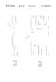
- FIGS. 3A-3H illustrate the problem of coplanarity in three-terminal bond-wireless packaging.
- a downset leadframe 402 and a silicon die 404 are aligned and brought in contact as in FIG. 3 B.
- constant pressure and minimal torque will squeeze both the gate lead 408 (the thin isolated lead) and the wider source metal 410 onto the die surface with equal force.
- FIG. 3D illustrates a downset lead 414 pressed properly onto the epoxy interlayer 416 to make good contact with a pad 418 .
- the downset lead 420 is parallel to the surface of the pad 418 but never touches, resulting in open circuit and a failed device.
- the lead 422 is twisted touching only on its heal while in FIG. 3G, only the toe of lead 424 touches epoxy 416 .
- lead 426 barely touches the epoxy 416 , but the contact is so light that it does not redistribute the epoxy 416 properly, resulting in a poor electrical contact.
- the outer edge of the top surface typically includes a metal ring shorted to the drain on the bottom surface, referred to as an equipotential ring or EQR, primarily introduced for purposes of achieving improved reliability against ionic migration.
- This outer ring is a source of risk for an accidental short between the source or gate connections during assembly.
- the silicon extends beyond this ring by another 20 to 70 ⁇ m.
- the protruding silicon varies in dimension due to the sawing process when the wafer is cut into separate dice. This area of the die is also biased at the drain potential and may short to a source or gate connected bond wire during packaging.
- a semiconductor package in accordance with this invention includes a semiconductor die having first and second principal surfaces, a heat sink electrically attached to a first terminal on the first principal surface of the die, and at least one lead electrically attached to at least one terminal on the second principal surface of the die.
- the lead is formed of a flat sheet of metal and extends laterally over opposite edges of the die. At the location where the lead passes over each of the opposite edges of the die, a notch is formed in the lead on the side of the lead that faces the die, thereby assuring that the lead does not come into electrical contact with a portion of the second principal surface adjacent the edge of the die.
- the die and at least a portion of the heat sink are encased in a conductive material such as plastic.
- the leads are symmetrical about an axis of the die.
- the opposite ends of the lead are normally bent, preferably at the end of the manufacturing process, to form surfaces that can be electrically mounted to a flat object such as a printed circuit board.
- the leads are symmetrical about the die, there is often no need for a central tie bar connecting the leads in the leadframe. Instead, the leads may be connected together in the leadframe by a pair of tie bars located on opposite sides of the leadframe.
- the die includes a power MOSFET, and at least two, electrically isolated leads are in electrical contact with the second principal surface of the die, a first lead making contact with a source terminal and a second lead making contact with a gate terminal.
- the heat sink is in electrical contact with a drain terminal of the die.
- a plurality of leads are in contact with the source terminal. The individual leads of the plurality may merge in the region where they contact the source terminal.
- the leads and heat sink are attached to the die with conductive epoxy or solder.
- the heat sink may include a rim and one or more notches to establish a firm connection between the heat sink and the plastic capsule.
- the capsule may be held back from a portion of one or more edges of the heat sink.
- An array of holes may be formed in a surface of the heat sink that is attached to the first principal surface of the die.
- the leads are bent away from the die so as to create a clearance between the leads and the portion of the second principal surface adjacent the edge of the die, in lieu of or in combination with, notches on the leads.
- a semiconductor package contains at least one sheet metal lead in contact with a surface of semiconductor die.
- a moat is formed on a side of the lead that is in contact with the die, the moat running parallel to an edge of the lead.
- the moat inhibits a die-attach material such as epoxy or solder (which is liquid while it is hot) from spreading out so as to create at short circuit.
- at least two adjacent leads are in contact with the die, and each of the leads contains a moat to prevent a short circuit from developing between the adjacent leads.
- This invention also includes a method of fabricating a lead frame for use in a semiconductor package.
- the process includes patterning a sheet of metal to form the lead frame and forming a notch in a surface of at least one of the leads.
- the notch can be formed by etching or stamping the metal.
- the notch typically has a depth that is equal to from 10% to 80% of the thickness of the metal sheet.
- the process also can include attaching the leadframe to a first principal surface of a semiconductor die such that the notch overlies at least one edge of the die. In many embodiments at least two notches are formed in the leadframe and the leadframe is attached to the die such that the at least two notches overlie opposite edges of the die.
- the process can also include attaching a heat sink to a second surface of the die.
- This invention also includes packages which contain more than one die, an arrangement that is made particularly achievable where the leadframe contains no central tie bar.
- FIG. 1A is a flow diagram of a known process for fabricating a power MOSFET package containing a bond-wireless source connection and a bond wire gate connection.
- FIGS. 1B-1G are views illustrating the process of FIG. 1 A.
- FIG. 2A is a flow diagram of a known process for fabricating a power MOSFET package containing a die-and-strap assembly.
- FIGS. 2B-2R are views illustrating the process of FIG. 2 A.
- FIGS. 3A-3H illustrate the problem of lead coplanarity in package design.
- FIGS. 4A and 4B illustrate the manner by which the epoxy or solder used in making a connection can spread outward and thereby cause a short between adjacent leads.
- FIG. 5 is a flow chart of a process sequence for fabricating a semiconductor package in accordance with this invention.
- FIGS. 6A-6F illustrate the steps of a process described in FIG. 5 .
- FIGS. 7A-7H illustrate the steps of a process of attaching at least two dice to a strip lead frame in accordance with this invention.
- FIGS. 8A-8F illustrate the steps of a process wherein the die is initially attached to the lead frame and then to the heat sink.
- FIGS. 8G-8J illustrate the steps of a process wherein the die is initially attached to the heat sink and then to the lead frame.
- FIGS. 9A-9D illustrate prospective views of a plastic capsule in accordance with this invention, showing various ways in which the heat sink may be exposed.
- FIGS. 9E-9H illustrate bottom views of the plastic capsules illustrated in FIGS. 9A-9D.
- FIGS. 10A and 10B are cross-sectional and bottom views, respectively, of a capsule containing a notched, T-shaped heat sink having a rim to secure the heat sink in the capsule.
- FIG. 10C is a cross-sectional view of a capsule similar to the one illustrated in FIGS. 10A and 10B, except that the heat sink protrudes from the bottom of the plastic capsule.
- FIG. 10D is a cross-sectional view of a heat sink having a second notch along its side to further secure the heat sink inside the capsule.
- FIG. 10E is a cross-sectional view of a T-shaped heat sink having a rim but no notch.
- FIGS. 10F and 10G are cross-sectional and bottom views, respectively, of a heat sink having a rim and a series of holes formed in the rim.
- FIGS. 10H and 10I are cross-sectional and bottom views, respectively, of a heat sink having a series of holes or depressions formed around its periphery to further secure the plastic.
- FIGS. 10J and 10K are cross-sectional and bottom views, respectively, of a heat sink and a die, the heat sink having an array of holes or depressions formed in its top surface.
- FIG. 10L is a cross-sectional view of a semiconductor package containing several of the features illustrated in FIGS. 10A-10K.
- FIGS. 11A and 11B illustrate top and cross-sectional views, respectively, of a lead frame which includes moats to prevent the epoxy or solder from creating a short between adjacent leads.
- FIGS. 12A-12F illustrate plan views of various shapes of leads that may be formed in accordance with this invention.
- FIGS. 13A-13F illustrate an alternative embodiment in which the lead frame is bent to ensure that it is spaced from the edge of the die.
- FIG. 5 illustrates a process sequence for fabricating a semiconductor package including a symmetrical lead frame in accordance with this invention.
- the process uses essentially three components: a semiconductor die, a symmetrical lead frame and a heat sink which is attached to the bottom of the die.
- a semiconductor die a symmetrical lead frame
- a heat sink which is attached to the bottom of the die.
- the die is initially attached to the symmetrical lead frame, using a conductive epoxy or soft solder. If an epoxy is used, the epoxy must be cured. Then the heat sink is attached to the bottom of the die, again using epoxy or solder. Alternatively, the die is initially attached to the heat sink and then to the lead frame. In either case, the result is a sandwich including the heat sink, the die and the symmetrical lead frame.
- a plastic capsule is then injection-molded around the die, the lead frame is trimmed to remove the outer tie bars, and the leads are bent or formed to allow them to be connected to a flat surface, such as circuit board.
- FIGS. 6A-6F illustrate a preferred process.
- the process is used to package a three-terminal die, such as a power MOSFET.
- MOSFET 110 includes a source terminal 112 , a gate terminal 114 and a drain terminal (not shown) which is on the bottom surface of die 110 .
- lead frame 100 includes a relatively large central portion 102 which will be attached to the source terminal 112 and a relatively thin lead 104 that will be attached to the gate terminal 114 .
- Portion 102 and lead 104 are connected together by tie bars 107 and 109 .
- Six cutouts 106 are formed in portion 102 , creating a total of eight source leads.
- Leadframe 100 is typically formed from a sheet of a metal such as aluminum or copper and is from 3 to 15 mils thick, with 6-7 mils being a common thickness
- FIG. 6B shows the underside of lead frame 100 .
- Notches 116 and 118 are formed in portion 102 in locations where portion 102 will overlie the edges of die 110 .
- notches 120 and 122 are formed in lead 104 .
- Notches 116 , 118 , 120 and 122 could have depths ranging from 10% to 80% of the total thickness of lead frame 100 . Typically, the depth of notches 116 , 118 , 120 and 122 would be approximately 20% of the thickness of lead frame 100 . For example, if lead frame 100 is six or seven mils thick, the notches would be approximately 2 mils (50 ⁇ m) deep.
- Notches 116 , 118 , 120 and 122 could be etched from the lead frame, using the known “half etch” process, or they could be formed using a stamping machine which could also be used to form holes 106 .
- Notches 116 , 118 , 120 and 122 need to be wide enough to allow for errors in the placement of the die, plus variations in the width of the saw blade (called the “kerf”) is used to separate the dice. Typically, the notches would be four mils wide and two mils deep.
- FIG. 6C shows lead frame 100 attached to die 110 by a layer of epoxy 124 , with notches 116 , 118 , 120 and 122 overhanging the edges of die 110 .
- the epoxy 124 can be applied to either the lead frame 100 or the die 110 , although typically the epoxy is applied to the lead frame.
- the lead frame 100 and die 110 are then placed in a die-attachment machine where they are squeezed together.
- the epoxy is then partially or fully cured so that it chemically reacts to the points, areas or regions of contact on lead frame 100 and die 110 .
- FIG. 6D shows the combination of lead frame 100 and die 110 with a heat sink 126 attached to the backside of die 110 .
- Heat sink 126 is attached to die 110 with epoxy in the same manner as described above.
- Heat sink 126 may be formed of copper and contains a lip 128 , the function of which is described below.
- leads 130 A- 130 F and 132 A and 132 B form structures that are symmetrical about an axis 131 of die 110 .
- the leads are held stable by only the outer tie bars 107 and 109 and did not require any central tie bars which produce the torque and twisting common to the asymmetrical designs described in the above-referenced application Ser. No. 09/322,127.
- FIG. 6F shows the structure after the leads 130 A- 130 F and 132 A and 132 B have been bent such that the bottoms of the outer portions of the leads are bent flat and are coplanar and can make contact with a flat surface, such as a printed circuit board.
- FIG. 6F also shows the plastic capsule 134 which encases the die 110 .
- Plastic capsule 134 does not cover the bottom surface of heat sink 126 , which is left exposed to provide an electrical contact with the backside of die 110 .
- heat sink 126 an edge of heat sink 126 is also left exposed (as shown by the arrow) to allow a visual confirmation that the epoxy or solder used to make a connection between heat sink 126 and a printed circuit board has properly wetted and flowed (and in the case of epoxy, evenly distributed) so as to establish a good electrical connection.
- heat sink 126 is a block of a metal, such as copper. While heat sink 126 serves to conduct heat away from die 110 , any block of metal could be used in place of heat sink 126 , whether or not in the particular application it serves primarily as a “heat sink” or thermal conductor. In some applications, the metal block could serve primarily as a low-resistance connection to the backside of the die. Thus, as used herein, the term “heat sink” includes any block or piece of metal that is used to form an electrical and/or thermal connection to the backside (bottom) of the die.
- a single lead frame may contain numerous repetitions of the source and gate leads illustrated in FIG. 6 A.
- lead frame 140 shown in FIG. 7A includes gate leads 140 G 1 and 140 G 2 and source leads 140 S 1 and 140 S 2 .
- FIG. 7B shows lead frame 140 with dice 142 A and 142 B positioned over the lead frame
- FIG. 7C shows dice 142 A and 142 B attached to lead frame 140 .
- FIG. 7D shows heat sinks 144 A and 144 B attached to dice 142 A and 142 B, respectively.
- dice 142 A and 142 B are enclosed in plastic capsules 146 A and 146 B, respectively.
- the tie bars are trimmed, leaving the structure illustrated in FIG. 7F with four leads protruding from each side of the package. As described above, six of the leads 148 A are connected to the source terminal and two of the leads 148 A are connected to the gate terminal. The leads 148 A are then bent to form a surface mount package, as shown in FIG. 7 G.
- FIG. 8A shows cross-sectional view of lead frame 140 positioned over die 142 A, with epoxy dots 150 on the surface of lead frame 140 .
- FIG. 8B shows die 142 attached to lead frame 140 .
- Epoxy dots 150 have spread out to form a single epoxy layer 152 . Note that the notches in lead frame 140 overlie the edges of die 142 A.
- FIG. 8C shows die 142 A positioned over heat sink 144 A, and FIG. 8D shows die 142 A and heat frame 144 A attached by an epoxy layer 154 .
- FIG. 8E shows the structure after a plastic capsule 156 has been injection-molded around die 142 A and heat sink 144 A, with leads 148 A protruding from either side.
- leads 148 A have been bent to form a surface mount package. Note that the bottom surface of heat sink 144 A is exposed.
- the attachment process can be reversed, with die 142 A being attached first to heat sink 144 A and then to lead frame 140 .
- FIGS. 9A-9D are perspective views showing various ways of exposing one or more edges of the heat sink to allow a visual inspection of the attachment between the heat sink and the surface on which it is mounted.
- FIG. 9A the entire periphery of the heat sink 144 A is exposed.
- FIG. 9B the opposite shorter edges of heat sink 144 A are exposed.
- FIG. 9C the opposite longer edges heat sink 144 A are exposed.
- FIG. 9D two opposite edges of heat sink 144 A are exposed and plastic capsule 156 is notched to allow segments of the other edges to be exposed.
- FIGS. 9E-9H are bottom views of the structures illustrated in FIGS. 9A-9E, respectively, where the dashed line represents the edge of the edge of the plastic capsule.
- FIG. 10A illustrates a notched, T-shaped heat sink 144 A which contains a rim 160 , as described above, as well as notch 158 on the underside of rim 160 .
- This arrangement “locks” the heat sink to the plastic capsule 156 and prevents delamination between the heat sink and the overlying die (not shown in FIG. 10 A).
- FIG. 10B is a bottom view of the structure illustrated in FIG. 10 A.
- FIG. 10C illustrates cross-sectional view of a variant in which the bottom of heat sink 144 protrudes slightly from the plastic 156 .
- FIG. 10E is a cross-sectional view of another form of heat sink 144 A containing a rim 160 but no notch.
- FIGS. 10F and 10G illustrate an alternative heat sink 144 A with holes 164 formed at intervals around the rim 160 . This further solidifies the attachment between the heat sink and surrounding plastic.
- FIGS. 10H and 10I Yet another form of T-shaped heat sink 144 is illustrated in FIGS. 10H and 10I where a series of holes 166 are formed in the top surface of the heat sink.
- holes 168 are also formed where the die 142 A is to be located.
- Holes 168 provide receptacles for the epoxy or solder that is used to attach die 142 A and heat sink 144 A, thereby improving the bond between these components.
- Holes 166 and 168 could be 10 to 50 ⁇ m in diameter, for example.
- FIG. 10L illustrates an embodiment combining many of the features described above, including rim 160 , notch 158 , holes 166 filled with plastic and holes 168 filled with the die-attach epoxy or solder.
- FIGS. 11A and 11B A solution to this problem is illustrated in FIGS. 11A and 11B, where moats 170 and 172 are formed in the adjacent leads 140 G 1 and 140 S 1 .
- Moats 170 and 172 provide volumes into which the epoxy may expand as lead frame 140 is pressed against die 142 A. Moats 170 and 172 are shown as being narrower than the notch 174 overlying the edge of die 142 A, but this need not be the case.
- the moats can be 0.25 to 4 mils wide (typically 1 mil) and 1 to 4 mils deep. Preferably, the depth and width of the moats are equal.
- Moats can be formed along the edges of any leads where there is a danger of a short from the spreading epoxy or solder.
- FIGS. 12A-12F show strip lead 184 attached to a die 182 and heat sink 180 , a structure that is useful for packaging diodes and other two-terminal devices.
- the lead 184 has a wider portion 184 A which contacts the die.
- FIG. 12C shows leads 190 and 192 having wider portions 190 A and 192 A, respectively, attached to the die 182 , a structure having three separate electrical terminals that is useful for packaging dual diodes, bipolar transistors, power MOSFETs, JFETs, and many other three-terminal devices.
- FIG. 12A shows strip lead 184 attached to a die 182 and heat sink 180 , a structure that is useful for packaging diodes and other two-terminal devices.
- the lead 184 has a wider portion 184 A which contacts the die.
- FIG. 12C shows leads 190 and 192 having wider portions 190 A and 192 A, respectively, attached to the die 182 , a structure having three separate electrical terminals that is useful for packaging dual dio
- FIG. 12D a strip lead 200 is combined with a lead 202 having a wider portion 202 A.
- FIG. 12E shows a strip lead 210 combined with a digitated lead 212 having a wider portion 212 A, a structure useful for packaging devices having three electrical connections where more than three pins are desired.
- FIG. 12F shows a strip lead 220 with an offset portion combined with a digitated lead 222 .
- the lead frame is bent to provide clearance where the lead frame passes over the edge of a die.
- lead frame 240 contains bends 246 and 248 which provide a spacing between lead frame 240 and the edges of a die 250 .
- FIG. 13B shows lead frame 240 attached to die 250 and
- FIG. 13C shows the same structure viewed from the bottom of the die.
- heat sink 260 is attached to the bottom of the die 250 . The completed structure is illustrated from the bottom of the heat sink 260 in FIG. 13 E and from the top of the lead frame 240 in FIG. 13 F.
Abstract
Description
Claims (3)
Priority Applications (7)
| Application Number | Priority Date | Filing Date | Title |
|---|---|---|---|
| US09/322,124 US6256200B1 (en) | 1999-05-27 | 1999-05-27 | Symmetrical package for semiconductor die |
| AU51752/00A AU5175200A (en) | 1999-05-27 | 2000-05-25 | Symmetrical package for semiconductor die |
| PCT/US2000/014959 WO2000074460A1 (en) | 1999-05-27 | 2000-05-25 | Symmetrical package for semiconductor die |
| CNB008097178A CN1261009C (en) | 1999-05-27 | 2000-05-25 | Symmetrical package for semiconductor die |
| TW089116854A TW516135B (en) | 1999-05-27 | 2000-08-19 | Symmetrical package for semiconductor die |
| US09/898,212 US6452802B2 (en) | 1999-05-27 | 2001-07-02 | Symmetrical package for semiconductor die |
| US10/066,023 US6800932B2 (en) | 1999-05-27 | 2002-01-30 | Package for semiconductor die containing symmetrical lead and heat sink |
Applications Claiming Priority (1)
| Application Number | Priority Date | Filing Date | Title |
|---|---|---|---|
| US09/322,124 US6256200B1 (en) | 1999-05-27 | 1999-05-27 | Symmetrical package for semiconductor die |
Related Child Applications (1)
| Application Number | Title | Priority Date | Filing Date |
|---|---|---|---|
| US09/898,212 Continuation US6452802B2 (en) | 1999-05-27 | 2001-07-02 | Symmetrical package for semiconductor die |
Publications (1)
| Publication Number | Publication Date |
|---|---|
| US6256200B1 true US6256200B1 (en) | 2001-07-03 |
Family
ID=23253533
Family Applications (3)
| Application Number | Title | Priority Date | Filing Date |
|---|---|---|---|
| US09/322,124 Expired - Lifetime US6256200B1 (en) | 1999-05-27 | 1999-05-27 | Symmetrical package for semiconductor die |
| US09/898,212 Expired - Lifetime US6452802B2 (en) | 1999-05-27 | 2001-07-02 | Symmetrical package for semiconductor die |
| US10/066,023 Expired - Lifetime US6800932B2 (en) | 1999-05-27 | 2002-01-30 | Package for semiconductor die containing symmetrical lead and heat sink |
Family Applications After (2)
| Application Number | Title | Priority Date | Filing Date |
|---|---|---|---|
| US09/898,212 Expired - Lifetime US6452802B2 (en) | 1999-05-27 | 2001-07-02 | Symmetrical package for semiconductor die |
| US10/066,023 Expired - Lifetime US6800932B2 (en) | 1999-05-27 | 2002-01-30 | Package for semiconductor die containing symmetrical lead and heat sink |
Country Status (5)
| Country | Link |
|---|---|
| US (3) | US6256200B1 (en) |
| CN (1) | CN1261009C (en) |
| AU (1) | AU5175200A (en) |
| TW (1) | TW516135B (en) |
| WO (1) | WO2000074460A1 (en) |
Cited By (95)
| Publication number | Priority date | Publication date | Assignee | Title |
|---|---|---|---|---|
| US20020125562A1 (en) * | 2000-03-27 | 2002-09-12 | Crowley Sean T. | Attaching semiconductor dies to substrates with conductive straps |
| US6521982B1 (en) * | 2000-06-02 | 2003-02-18 | Amkor Technology, Inc. | Packaging high power integrated circuit devices |
| US6566164B1 (en) | 2000-12-07 | 2003-05-20 | Amkor Technology, Inc. | Exposed copper strap in a semiconductor package |
| US6630726B1 (en) | 2001-11-07 | 2003-10-07 | Amkor Technology, Inc. | Power semiconductor package with strap |
| US6689642B2 (en) * | 2000-03-24 | 2004-02-10 | Sanyo Electric Co., Ltd. | Semiconductor device and manufacturing method thereof |
| US6740969B1 (en) * | 1999-08-25 | 2004-05-25 | Renesas Technology Corp. | Electronic device |
| US6750545B1 (en) | 2003-02-28 | 2004-06-15 | Amkor Technology, Inc. | Semiconductor package capable of die stacking |
| US6756658B1 (en) | 2001-04-06 | 2004-06-29 | Amkor Technology, Inc. | Making two lead surface mounting high power microleadframe semiconductor packages |
| US20040150086A1 (en) * | 1999-10-15 | 2004-08-05 | Lee Tae Heon | Semiconductor package having reduced thickness |
| US6777789B1 (en) | 2001-03-20 | 2004-08-17 | Amkor Technology, Inc. | Mounting for a package containing a chip |
| US6791181B2 (en) * | 2000-11-29 | 2004-09-14 | Mitsubishi Chemical Corporation | Semiconductor light emitting device |
| US6794740B1 (en) | 2003-03-13 | 2004-09-21 | Amkor Technology, Inc. | Leadframe package for semiconductor devices |
| US6798047B1 (en) | 2002-12-26 | 2004-09-28 | Amkor Technology, Inc. | Pre-molded leadframe |
| US6818973B1 (en) | 2002-09-09 | 2004-11-16 | Amkor Technology, Inc. | Exposed lead QFP package fabricated through the use of a partial saw process |
| US6849930B2 (en) * | 2000-08-31 | 2005-02-01 | Nec Corporation | Semiconductor device with uneven metal plate to improve adhesion to molding compound |
| US20050023670A1 (en) * | 2003-07-31 | 2005-02-03 | Renesas Technology Corp. | Semiconductor device and a method of manufacturing the same |
| US20050167802A1 (en) * | 2004-01-30 | 2005-08-04 | Denso Corporation | Semiconductor device |
| US7012282B1 (en) * | 2002-05-21 | 2006-03-14 | National Semiconductor Corporation | Bumped integrated circuits for optical applications |
| EP1685596A2 (en) * | 2003-11-08 | 2006-08-02 | Robert Bosch Gmbh | Electric motor and method for producing said motor |
| US7183630B1 (en) | 2002-04-15 | 2007-02-27 | Amkor Technology, Inc. | Lead frame with plated end leads |
| US20070090499A1 (en) * | 2002-08-19 | 2007-04-26 | Nec Electronics Corporation | Production process for manufacturing such semiconductor package |
| US20070090463A1 (en) * | 2005-10-20 | 2007-04-26 | Tan Xiaochun | Semiconductor devices with multiple heat sinks |
| US20080211082A1 (en) * | 1999-02-17 | 2008-09-04 | Hitachi, Ltd. | Semiconductor device and a method of manufacturing the same |
| US20080277770A1 (en) * | 2007-04-27 | 2008-11-13 | Kabushiki Kaisha Toshiba | Semiconductor device |
| US20090224380A1 (en) * | 2008-03-04 | 2009-09-10 | Powertech Technology Inc. | Leadframe and semiconductor package having downset baffle paddles |
| US7619307B1 (en) * | 2008-06-05 | 2009-11-17 | Powertech Technology Inc. | Leadframe-based semiconductor package having arched bend in a supporting bar and leadframe for the package |
| US7687893B2 (en) | 2006-12-27 | 2010-03-30 | Amkor Technology, Inc. | Semiconductor package having leadframe with exposed anchor pads |
| US7687899B1 (en) | 2007-08-07 | 2010-03-30 | Amkor Technology, Inc. | Dual laminate package structure with embedded elements |
| US7692286B1 (en) | 2002-11-08 | 2010-04-06 | Amkor Technology, Inc. | Two-sided fan-out wafer escape package |
| US7723210B2 (en) | 2002-11-08 | 2010-05-25 | Amkor Technology, Inc. | Direct-write wafer level chip scale package |
| US7723852B1 (en) | 2008-01-21 | 2010-05-25 | Amkor Technology, Inc. | Stacked semiconductor package and method of making same |
| US7732899B1 (en) | 2005-12-02 | 2010-06-08 | Amkor Technology, Inc. | Etch singulated semiconductor package |
| US7768135B1 (en) | 2008-04-17 | 2010-08-03 | Amkor Technology, Inc. | Semiconductor package with fast power-up cycle and method of making same |
| US7777351B1 (en) | 2007-10-01 | 2010-08-17 | Amkor Technology, Inc. | Thin stacked interposer package |
| US7808084B1 (en) | 2008-05-06 | 2010-10-05 | Amkor Technology, Inc. | Semiconductor package with half-etched locking features |
| US7829990B1 (en) | 2007-01-18 | 2010-11-09 | Amkor Technology, Inc. | Stackable semiconductor package including laminate interposer |
| US20100295187A1 (en) * | 2007-12-20 | 2010-11-25 | Aisin Aw Co., Ltd. | Semiconductor device and method for fabricating the same |
| US7847386B1 (en) | 2007-11-05 | 2010-12-07 | Amkor Technology, Inc. | Reduced size stacked semiconductor package and method of making the same |
| US7847392B1 (en) | 2008-09-30 | 2010-12-07 | Amkor Technology, Inc. | Semiconductor device including leadframe with increased I/O |
| US7875963B1 (en) | 2008-11-21 | 2011-01-25 | Amkor Technology, Inc. | Semiconductor device including leadframe having power bars and increased I/O |
| US7902660B1 (en) | 2006-05-24 | 2011-03-08 | Amkor Technology, Inc. | Substrate for semiconductor device and manufacturing method thereof |
| US7928542B2 (en) | 2001-03-27 | 2011-04-19 | Amkor Technology, Inc. | Lead frame for semiconductor package |
| US7956453B1 (en) | 2008-01-16 | 2011-06-07 | Amkor Technology, Inc. | Semiconductor package with patterning layer and method of making same |
| US7960818B1 (en) | 2009-03-04 | 2011-06-14 | Amkor Technology, Inc. | Conformal shield on punch QFN semiconductor package |
| US7968998B1 (en) | 2006-06-21 | 2011-06-28 | Amkor Technology, Inc. | Side leaded, bottom exposed pad and bottom exposed lead fusion quad flat semiconductor package |
| US7977163B1 (en) | 2005-12-08 | 2011-07-12 | Amkor Technology, Inc. | Embedded electronic component package fabrication method |
| US7977774B2 (en) | 2007-07-10 | 2011-07-12 | Amkor Technology, Inc. | Fusion quad flat semiconductor package |
| US7982297B1 (en) | 2007-03-06 | 2011-07-19 | Amkor Technology, Inc. | Stackable semiconductor package having partially exposed semiconductor die and method of fabricating the same |
| US7982298B1 (en) | 2008-12-03 | 2011-07-19 | Amkor Technology, Inc. | Package in package semiconductor device |
| US7989933B1 (en) | 2008-10-06 | 2011-08-02 | Amkor Technology, Inc. | Increased I/O leadframe and semiconductor device including same |
| US8008758B1 (en) | 2008-10-27 | 2011-08-30 | Amkor Technology, Inc. | Semiconductor device with increased I/O leadframe |
| US8026589B1 (en) | 2009-02-23 | 2011-09-27 | Amkor Technology, Inc. | Reduced profile stackable semiconductor package |
| US8058715B1 (en) | 2009-01-09 | 2011-11-15 | Amkor Technology, Inc. | Package in package device for RF transceiver module |
| US8067821B1 (en) | 2008-04-10 | 2011-11-29 | Amkor Technology, Inc. | Flat semiconductor package with half package molding |
| US8072050B1 (en) | 2008-11-18 | 2011-12-06 | Amkor Technology, Inc. | Semiconductor device with increased I/O leadframe including passive device |
| US8089159B1 (en) | 2007-10-03 | 2012-01-03 | Amkor Technology, Inc. | Semiconductor package with increased I/O density and method of making the same |
| US8089145B1 (en) | 2008-11-17 | 2012-01-03 | Amkor Technology, Inc. | Semiconductor device including increased capacity leadframe |
| US8125064B1 (en) | 2008-07-28 | 2012-02-28 | Amkor Technology, Inc. | Increased I/O semiconductor package and method of making same |
| US8184453B1 (en) | 2008-07-31 | 2012-05-22 | Amkor Technology, Inc. | Increased capacity semiconductor package |
| US8294276B1 (en) | 2010-05-27 | 2012-10-23 | Amkor Technology, Inc. | Semiconductor device and fabricating method thereof |
| US8318287B1 (en) | 1998-06-24 | 2012-11-27 | Amkor Technology, Inc. | Integrated circuit package and method of making the same |
| US20120299166A1 (en) * | 2010-12-10 | 2012-11-29 | Masanori Minamio | Conduction path, semiconductor device using the same, and method of manufacturing conduction path, and semiconductor device |
| US8324511B1 (en) | 2010-04-06 | 2012-12-04 | Amkor Technology, Inc. | Through via nub reveal method and structure |
| US20130034937A1 (en) * | 2011-04-05 | 2013-02-07 | Texas Instruments Incorporated | Exposed Die Package for Direct Surface Mounting |
| US8390130B1 (en) | 2011-01-06 | 2013-03-05 | Amkor Technology, Inc. | Through via recessed reveal structure and method |
| US8410585B2 (en) | 2000-04-27 | 2013-04-02 | Amkor Technology, Inc. | Leadframe and semiconductor package made using the leadframe |
| US8440554B1 (en) | 2010-08-02 | 2013-05-14 | Amkor Technology, Inc. | Through via connected backside embedded circuit features structure and method |
| US8487445B1 (en) | 2010-10-05 | 2013-07-16 | Amkor Technology, Inc. | Semiconductor device having through electrodes protruding from dielectric layer |
| US8487420B1 (en) | 2008-12-08 | 2013-07-16 | Amkor Technology, Inc. | Package in package semiconductor device with film over wire |
| US8552548B1 (en) | 2011-11-29 | 2013-10-08 | Amkor Technology, Inc. | Conductive pad on protruding through electrode semiconductor device |
| US8575742B1 (en) | 2009-04-06 | 2013-11-05 | Amkor Technology, Inc. | Semiconductor device with increased I/O leadframe including power bars |
| US8648450B1 (en) | 2011-01-27 | 2014-02-11 | Amkor Technology, Inc. | Semiconductor device including leadframe with a combination of leads and lands |
| US8674485B1 (en) | 2010-12-08 | 2014-03-18 | Amkor Technology, Inc. | Semiconductor device including leadframe with downsets |
| US8680656B1 (en) | 2009-01-05 | 2014-03-25 | Amkor Technology, Inc. | Leadframe structure for concentrated photovoltaic receiver package |
| US8791501B1 (en) | 2010-12-03 | 2014-07-29 | Amkor Technology, Inc. | Integrated passive device structure and method |
| US8796561B1 (en) | 2009-10-05 | 2014-08-05 | Amkor Technology, Inc. | Fan out build up substrate stackable package and method |
| US20140291825A1 (en) * | 2013-04-02 | 2014-10-02 | Mitsubishi Electric Corporation | Semiconductor device and semiconductor module |
| US8937381B1 (en) | 2009-12-03 | 2015-01-20 | Amkor Technology, Inc. | Thin stackable package and method |
| US9048298B1 (en) | 2012-03-29 | 2015-06-02 | Amkor Technology, Inc. | Backside warpage control structure and fabrication method |
| US20150235928A1 (en) * | 2011-04-05 | 2015-08-20 | Panasonic Intellectual Property Management Co., Ltd. | Encapsulated semiconductor device and method for manufacturing the same |
| US9129943B1 (en) | 2012-03-29 | 2015-09-08 | Amkor Technology, Inc. | Embedded component package and fabrication method |
| US9184118B2 (en) | 2013-05-02 | 2015-11-10 | Amkor Technology Inc. | Micro lead frame structure having reinforcing portions and method |
| US9184148B2 (en) | 2013-10-24 | 2015-11-10 | Amkor Technology, Inc. | Semiconductor package and method therefor |
| US20160043189A1 (en) * | 2014-08-07 | 2016-02-11 | Semiconductor Components Industries, Llc | Semiconductor package for a lateral device and related methods |
| US9275921B2 (en) * | 2014-01-30 | 2016-03-01 | Kabushiki Kaisha Toshiba | Semiconductor device |
| US20160277017A1 (en) * | 2011-09-13 | 2016-09-22 | Fsp Technology Inc. | Snubber circuit |
| US20160336251A1 (en) * | 2015-05-11 | 2016-11-17 | Denso Corporation | Semiconductor device |
| US9631481B1 (en) | 2011-01-27 | 2017-04-25 | Amkor Technology, Inc. | Semiconductor device including leadframe with a combination of leads and lands and method |
| US9673122B2 (en) | 2014-05-02 | 2017-06-06 | Amkor Technology, Inc. | Micro lead frame structure having reinforcing portions and method |
| US9691734B1 (en) | 2009-12-07 | 2017-06-27 | Amkor Technology, Inc. | Method of forming a plurality of electronic component packages |
| US9704725B1 (en) | 2012-03-06 | 2017-07-11 | Amkor Technology, Inc. | Semiconductor device with leadframe configured to facilitate reduced burr formation |
| US20190097524A1 (en) * | 2011-09-13 | 2019-03-28 | Fsp Technology Inc. | Circuit having snubber circuit in power supply device |
| US10811341B2 (en) | 2009-01-05 | 2020-10-20 | Amkor Technology Singapore Holding Pte Ltd. | Semiconductor device with through-mold via |
| US11056422B2 (en) * | 2018-05-29 | 2021-07-06 | Shindengen Electric Manufacturing Co., Ltd. | Semiconductor module |
| US20230154827A1 (en) * | 2021-11-12 | 2023-05-18 | Infineon Technologies Ag | Dual functional thermal performance semiconductor package and related methods of manufacturing |
Families Citing this family (39)
| Publication number | Priority date | Publication date | Assignee | Title |
|---|---|---|---|---|
| US6777786B2 (en) * | 2001-03-12 | 2004-08-17 | Fairchild Semiconductor Corporation | Semiconductor device including stacked dies mounted on a leadframe |
| US6919625B2 (en) * | 2003-07-10 | 2005-07-19 | General Semiconductor, Inc. | Surface mount multichip devices |
| DE10345247B4 (en) * | 2003-09-29 | 2007-10-04 | Infineon Technologies Ag | Use of conductor tracks as Krallkörper |
| US7432595B2 (en) * | 2003-12-04 | 2008-10-07 | Great Wall Semiconductor Corporation | System and method to reduce metal series resistance of bumped chip |
| WO2005059957A2 (en) * | 2003-12-12 | 2005-06-30 | Great Wall Semiconductor Corporation | Metal interconnect system and method for direct die attachment |
| US7132314B2 (en) * | 2004-05-28 | 2006-11-07 | Texas Instruments Incorporated | System and method for forming one or more integrated circuit packages using a flexible leadframe structure |
| DE102004041088B4 (en) * | 2004-08-24 | 2009-07-02 | Infineon Technologies Ag | Semiconductor component in flat conductor technology with a semiconductor chip and method for its production |
| US7202113B2 (en) * | 2005-06-09 | 2007-04-10 | Ming Sun | Wafer level bumpless method of making a flip chip mounted semiconductor device package |
| US8334583B2 (en) * | 2005-07-20 | 2012-12-18 | Infineon Technologies Ag | Leadframe strip and mold apparatus for an electronic component and method of encapsulating an electronic component |
| JP4764692B2 (en) * | 2005-09-29 | 2011-09-07 | 日立オートモティブシステムズ株式会社 | Semiconductor module |
| CN101460779A (en) | 2005-12-21 | 2009-06-17 | 科锐Led照明技术公司 | Lighting device |
| US7572675B2 (en) * | 2006-01-24 | 2009-08-11 | Asm Technology Singapore Pte Ltd. | Mold flash removal process for electronic devices |
| US7648257B2 (en) * | 2006-04-21 | 2010-01-19 | Cree, Inc. | Light emitting diode packages |
| EP2066968B1 (en) * | 2006-09-18 | 2016-04-27 | Cree, Inc. | Lighting devices, lighting assemblies, fixtures and methods using same |
| US8827507B2 (en) * | 2006-09-21 | 2014-09-09 | Cree, Inc. | Lighting assemblies, methods of installing same, and methods of replacing lights |
| JP5324458B2 (en) * | 2006-11-14 | 2013-10-23 | クリー インコーポレイテッド | Lighting assembly and components for the lighting assembly |
| US9605828B2 (en) * | 2006-11-14 | 2017-03-28 | Cree, Inc. | Light engine assemblies |
| US7967480B2 (en) * | 2007-05-03 | 2011-06-28 | Cree, Inc. | Lighting fixture |
| WO2008137905A1 (en) | 2007-05-07 | 2008-11-13 | Cree Led Lighting Solutions, Inc. | Light fixtures and lighting devices |
| US7821111B2 (en) * | 2007-10-05 | 2010-10-26 | Texas Instruments Incorporated | Semiconductor device having grooved leads to confine solder wicking |
| US7800219B2 (en) * | 2008-01-02 | 2010-09-21 | Fairchild Semiconductor Corporation | High-power semiconductor die packages with integrated heat-sink capability and methods of manufacturing the same |
| US7960845B2 (en) | 2008-01-03 | 2011-06-14 | Linear Technology Corporation | Flexible contactless wire bonding structure and methodology for semiconductor device |
| US8240875B2 (en) | 2008-06-25 | 2012-08-14 | Cree, Inc. | Solid state linear array modules for general illumination |
| US7902665B2 (en) * | 2008-09-02 | 2011-03-08 | Linear Technology Corporation | Semiconductor device having a suspended isolating interconnect |
| US8124449B2 (en) | 2008-12-02 | 2012-02-28 | Infineon Technologies Ag | Device including a semiconductor chip and metal foils |
| JP5822468B2 (en) * | 2011-01-11 | 2015-11-24 | ローム株式会社 | Semiconductor device |
| JP5615757B2 (en) * | 2011-04-06 | 2014-10-29 | 新電元工業株式会社 | Semiconductor device, connector, and manufacturing method of semiconductor device |
| JP2013149779A (en) * | 2012-01-19 | 2013-08-01 | Semiconductor Components Industries Llc | Semiconductor device |
| TWI488341B (en) * | 2012-04-11 | 2015-06-11 | Lite On Electronics Guangzhou | Insulator-integrated leadframe assembly, led package and led light bar |
| CN103367344B (en) * | 2012-04-11 | 2016-04-27 | 光宝电子(广州)有限公司 | Connecting plate tablet, LED package product and light-emitting diode light bar |
| CN105552039B (en) * | 2014-10-24 | 2019-08-13 | 意法半导体股份有限公司 | Electronic device and manufacturing method with the encapsulating structure for improving electric accessibility |
| DE102015104996B4 (en) * | 2015-03-31 | 2020-06-18 | Infineon Technologies Austria Ag | Semiconductor devices with control and load lines from opposite directions |
| USD904322S1 (en) | 2019-08-28 | 2020-12-08 | Carbice Corporation | Flexible heat sink |
| USD906269S1 (en) | 2019-08-28 | 2020-12-29 | Carbice Corporation | Flexible heat sink |
| US20210063099A1 (en) | 2019-08-28 | 2021-03-04 | Carbice Corporation | Flexible and conformable polymer-based heat sinks and methods of making and using thereof |
| USD903610S1 (en) | 2019-08-28 | 2020-12-01 | Carbice Corporation | Flexible heat sink |
| EP3790047B1 (en) * | 2019-09-05 | 2022-03-02 | Infineon Technologies AG | Multi-chip-package |
| IT202000008269A1 (en) | 2020-04-17 | 2021-10-17 | St Microelectronics Srl | STACKABLE ENCAPSULATED ELECTRONIC POWER DEVICE FOR SURFACE MOUNTING AND CIRCUIT ARRANGEMENT |
| NL2026503B1 (en) * | 2020-09-18 | 2022-05-23 | Ampleon Netherlands Bv | Molded RF power package |
Citations (3)
| Publication number | Priority date | Publication date | Assignee | Title |
|---|---|---|---|---|
| US5545921A (en) * | 1994-11-04 | 1996-08-13 | International Business Machines, Corporation | Personalized area leadframe coining or half etching for reduced mechanical stress at device edge |
| US5554885A (en) * | 1993-06-04 | 1996-09-10 | Seiko Epson Corporation | Semiconductor device including means for dispersing and absorbing tensile forces acting on film tape |
| US6005286A (en) * | 1997-10-06 | 1999-12-21 | Micron Technology, Inc. | Increasing the gap between a lead frame and a semiconductor die |
Family Cites Families (11)
| Publication number | Priority date | Publication date | Assignee | Title |
|---|---|---|---|---|
| DE3684184D1 (en) * | 1985-06-20 | 1992-04-16 | Toshiba Kawasaki Kk | ENCLOSED SEMICONDUCTOR ARRANGEMENT. |
| JPH02155256A (en) * | 1988-12-08 | 1990-06-14 | Mitsubishi Electric Corp | Semiconductor device |
| US5105259A (en) * | 1990-09-28 | 1992-04-14 | Motorola, Inc. | Thermally enhanced semiconductor device utilizing a vacuum to ultimately enhance thermal dissipation |
| JPH05211250A (en) * | 1992-01-30 | 1993-08-20 | Nec Corp | Resin-sealed type semiconductor device |
| US5177669A (en) * | 1992-03-02 | 1993-01-05 | Motorola, Inc. | Molded ring integrated circuit package |
| US5652461A (en) * | 1992-06-03 | 1997-07-29 | Seiko Epson Corporation | Semiconductor device with a convex heat sink |
| US5598034A (en) * | 1992-07-22 | 1997-01-28 | Vlsi Packaging Corporation | Plastic packaging of microelectronic circuit devices |
| US5485037A (en) * | 1993-04-12 | 1996-01-16 | Amkor Electronics, Inc. | Semiconductor device having a thermal dissipator and electromagnetic shielding |
| US5625226A (en) * | 1994-09-19 | 1997-04-29 | International Rectifier Corporation | Surface mount package with improved heat transfer |
| JP3170182B2 (en) * | 1995-08-15 | 2001-05-28 | 株式会社東芝 | Resin-sealed semiconductor device and method of manufacturing the same |
| KR100259080B1 (en) * | 1998-02-11 | 2000-06-15 | 김영환 | Lead frame having heat spread and semiconductor package with such lead frame |
-
1999
- 1999-05-27 US US09/322,124 patent/US6256200B1/en not_active Expired - Lifetime
-
2000
- 2000-05-25 AU AU51752/00A patent/AU5175200A/en not_active Abandoned
- 2000-05-25 CN CNB008097178A patent/CN1261009C/en not_active Expired - Fee Related
- 2000-05-25 WO PCT/US2000/014959 patent/WO2000074460A1/en active Application Filing
- 2000-08-19 TW TW089116854A patent/TW516135B/en not_active IP Right Cessation
-
2001
- 2001-07-02 US US09/898,212 patent/US6452802B2/en not_active Expired - Lifetime
-
2002
- 2002-01-30 US US10/066,023 patent/US6800932B2/en not_active Expired - Lifetime
Patent Citations (3)
| Publication number | Priority date | Publication date | Assignee | Title |
|---|---|---|---|---|
| US5554885A (en) * | 1993-06-04 | 1996-09-10 | Seiko Epson Corporation | Semiconductor device including means for dispersing and absorbing tensile forces acting on film tape |
| US5545921A (en) * | 1994-11-04 | 1996-08-13 | International Business Machines, Corporation | Personalized area leadframe coining or half etching for reduced mechanical stress at device edge |
| US6005286A (en) * | 1997-10-06 | 1999-12-21 | Micron Technology, Inc. | Increasing the gap between a lead frame and a semiconductor die |
Cited By (170)
| Publication number | Priority date | Publication date | Assignee | Title |
|---|---|---|---|---|
| US8318287B1 (en) | 1998-06-24 | 2012-11-27 | Amkor Technology, Inc. | Integrated circuit package and method of making the same |
| US8853836B1 (en) | 1998-06-24 | 2014-10-07 | Amkor Technology, Inc. | Integrated circuit package and method of making the same |
| US8963301B1 (en) | 1998-06-24 | 2015-02-24 | Amkor Technology, Inc. | Integrated circuit package and method of making the same |
| US9224676B1 (en) | 1998-06-24 | 2015-12-29 | Amkor Technology, Inc. | Integrated circuit package and method of making the same |
| US20080211082A1 (en) * | 1999-02-17 | 2008-09-04 | Hitachi, Ltd. | Semiconductor device and a method of manufacturing the same |
| US7812464B2 (en) * | 1999-02-17 | 2010-10-12 | Renesas Electronics Corporation | Semiconductor device and a method of manufacturing for high output MOSFET |
| US6740969B1 (en) * | 1999-08-25 | 2004-05-25 | Renesas Technology Corp. | Electronic device |
| US20040150086A1 (en) * | 1999-10-15 | 2004-08-05 | Lee Tae Heon | Semiconductor package having reduced thickness |
| US6707138B2 (en) | 1999-12-01 | 2004-03-16 | Amkor Technology, Inc. | Semiconductor device including metal strap electrically coupled between semiconductor die and metal leadframe |
| US6689642B2 (en) * | 2000-03-24 | 2004-02-10 | Sanyo Electric Co., Ltd. | Semiconductor device and manufacturing method thereof |
| US20020125562A1 (en) * | 2000-03-27 | 2002-09-12 | Crowley Sean T. | Attaching semiconductor dies to substrates with conductive straps |
| US6459147B1 (en) | 2000-03-27 | 2002-10-01 | Amkor Technology, Inc. | Attaching semiconductor dies to substrates with conductive straps |
| US8410585B2 (en) | 2000-04-27 | 2013-04-02 | Amkor Technology, Inc. | Leadframe and semiconductor package made using the leadframe |
| US9362210B2 (en) | 2000-04-27 | 2016-06-07 | Amkor Technology, Inc. | Leadframe and semiconductor package made using the leadframe |
| US6521982B1 (en) * | 2000-06-02 | 2003-02-18 | Amkor Technology, Inc. | Packaging high power integrated circuit devices |
| US6849930B2 (en) * | 2000-08-31 | 2005-02-01 | Nec Corporation | Semiconductor device with uneven metal plate to improve adhesion to molding compound |
| US6791181B2 (en) * | 2000-11-29 | 2004-09-14 | Mitsubishi Chemical Corporation | Semiconductor light emitting device |
| US6723582B2 (en) | 2000-12-07 | 2004-04-20 | Amkor Technology, Inc. | Method of making a semiconductor package having exposed metal strap |
| US6566164B1 (en) | 2000-12-07 | 2003-05-20 | Amkor Technology, Inc. | Exposed copper strap in a semiconductor package |
| US6777789B1 (en) | 2001-03-20 | 2004-08-17 | Amkor Technology, Inc. | Mounting for a package containing a chip |
| US7928542B2 (en) | 2001-03-27 | 2011-04-19 | Amkor Technology, Inc. | Lead frame for semiconductor package |
| US8102037B2 (en) | 2001-03-27 | 2012-01-24 | Amkor Technology, Inc. | Leadframe for semiconductor package |
| US6756658B1 (en) | 2001-04-06 | 2004-06-29 | Amkor Technology, Inc. | Making two lead surface mounting high power microleadframe semiconductor packages |
| US6630726B1 (en) | 2001-11-07 | 2003-10-07 | Amkor Technology, Inc. | Power semiconductor package with strap |
| US7183630B1 (en) | 2002-04-15 | 2007-02-27 | Amkor Technology, Inc. | Lead frame with plated end leads |
| US7012282B1 (en) * | 2002-05-21 | 2006-03-14 | National Semiconductor Corporation | Bumped integrated circuits for optical applications |
| US7449370B2 (en) * | 2002-08-19 | 2008-11-11 | Nec Electronics Corporation | Production process for manufacturing such semiconductor package |
| US20070090499A1 (en) * | 2002-08-19 | 2007-04-26 | Nec Electronics Corporation | Production process for manufacturing such semiconductor package |
| US6818973B1 (en) | 2002-09-09 | 2004-11-16 | Amkor Technology, Inc. | Exposed lead QFP package fabricated through the use of a partial saw process |
| US9406645B1 (en) | 2002-11-08 | 2016-08-02 | Amkor Technology, Inc. | Wafer level package and fabrication method |
| US7692286B1 (en) | 2002-11-08 | 2010-04-06 | Amkor Technology, Inc. | Two-sided fan-out wafer escape package |
| US8691632B1 (en) | 2002-11-08 | 2014-04-08 | Amkor Technology, Inc. | Wafer level package and fabrication method |
| US8710649B1 (en) | 2002-11-08 | 2014-04-29 | Amkor Technology, Inc. | Wafer level package and fabrication method |
| US10665567B1 (en) | 2002-11-08 | 2020-05-26 | Amkor Technology, Inc. | Wafer level package and fabrication method |
| US9871015B1 (en) | 2002-11-08 | 2018-01-16 | Amkor Technology, Inc. | Wafer level package and fabrication method |
| US8486764B1 (en) | 2002-11-08 | 2013-07-16 | Amkor Technology, Inc. | Wafer level package and fabrication method |
| US7932595B1 (en) | 2002-11-08 | 2011-04-26 | Amkor Technology, Inc. | Electronic component package comprising fan-out traces |
| US8119455B1 (en) | 2002-11-08 | 2012-02-21 | Amkor Technology, Inc. | Wafer level package fabrication method |
| US8501543B1 (en) | 2002-11-08 | 2013-08-06 | Amkor Technology, Inc. | Direct-write wafer level chip scale package |
| US7714431B1 (en) | 2002-11-08 | 2010-05-11 | Amkor Technology, Inc. | Electronic component package comprising fan-out and fan-in traces |
| US7723210B2 (en) | 2002-11-08 | 2010-05-25 | Amkor Technology, Inc. | Direct-write wafer level chip scale package |
| US8298866B1 (en) | 2002-11-08 | 2012-10-30 | Amkor Technology, Inc. | Wafer level package and fabrication method |
| US8188584B1 (en) | 2002-11-08 | 2012-05-29 | Amkor Technology, Inc. | Direct-write wafer level chip scale package |
| US9054117B1 (en) | 2002-11-08 | 2015-06-09 | Amkor Technology, Inc. | Wafer level package and fabrication method |
| US8952522B1 (en) | 2002-11-08 | 2015-02-10 | Amkor Technology, Inc. | Wafer level package and fabrication method |
| US6798047B1 (en) | 2002-12-26 | 2004-09-28 | Amkor Technology, Inc. | Pre-molded leadframe |
| US6750545B1 (en) | 2003-02-28 | 2004-06-15 | Amkor Technology, Inc. | Semiconductor package capable of die stacking |
| US6794740B1 (en) | 2003-03-13 | 2004-09-21 | Amkor Technology, Inc. | Leadframe package for semiconductor devices |
| US6992386B2 (en) * | 2003-07-31 | 2006-01-31 | Renesas Technology Corp. | Semiconductor device and a method of manufacturing the same |
| US20080272472A1 (en) * | 2003-07-31 | 2008-11-06 | Renesas Technology Corp. | Semiconductor packaging device comprising a semiconductor chip including a MOSFET |
| US20050023670A1 (en) * | 2003-07-31 | 2005-02-03 | Renesas Technology Corp. | Semiconductor device and a method of manufacturing the same |
| US7408251B2 (en) | 2003-07-31 | 2008-08-05 | Renesas Technology Corp. | Semiconductor packaging device comprising a semiconductor chip including a MOSFET |
| US20060097391A1 (en) * | 2003-07-31 | 2006-05-11 | Renesas Technology Corp. | Semiconductor device and a method of manufacturing the same |
| US7586180B2 (en) | 2003-07-31 | 2009-09-08 | Renesas Technology Corp. | Semiconductor packaging device comprising a semiconductor chip including a MOSFET |
| EP1685596A2 (en) * | 2003-11-08 | 2006-08-02 | Robert Bosch Gmbh | Electric motor and method for producing said motor |
| US20050167802A1 (en) * | 2004-01-30 | 2005-08-04 | Denso Corporation | Semiconductor device |
| US7786555B2 (en) * | 2005-10-20 | 2010-08-31 | Diodes, Incorporated | Semiconductor devices with multiple heat sinks |
| US20070090463A1 (en) * | 2005-10-20 | 2007-04-26 | Tan Xiaochun | Semiconductor devices with multiple heat sinks |
| US7732899B1 (en) | 2005-12-02 | 2010-06-08 | Amkor Technology, Inc. | Etch singulated semiconductor package |
| US7977163B1 (en) | 2005-12-08 | 2011-07-12 | Amkor Technology, Inc. | Embedded electronic component package fabrication method |
| US7902660B1 (en) | 2006-05-24 | 2011-03-08 | Amkor Technology, Inc. | Substrate for semiconductor device and manufacturing method thereof |
| US8441110B1 (en) | 2006-06-21 | 2013-05-14 | Amkor Technology, Inc. | Side leaded, bottom exposed pad and bottom exposed lead fusion quad flat semiconductor package |
| US7968998B1 (en) | 2006-06-21 | 2011-06-28 | Amkor Technology, Inc. | Side leaded, bottom exposed pad and bottom exposed lead fusion quad flat semiconductor package |
| US8089141B1 (en) | 2006-12-27 | 2012-01-03 | Amkor Technology, Inc. | Semiconductor package having leadframe with exposed anchor pads |
| US7687893B2 (en) | 2006-12-27 | 2010-03-30 | Amkor Technology, Inc. | Semiconductor package having leadframe with exposed anchor pads |
| US7829990B1 (en) | 2007-01-18 | 2010-11-09 | Amkor Technology, Inc. | Stackable semiconductor package including laminate interposer |
| US7982297B1 (en) | 2007-03-06 | 2011-07-19 | Amkor Technology, Inc. | Stackable semiconductor package having partially exposed semiconductor die and method of fabricating the same |
| US20080277770A1 (en) * | 2007-04-27 | 2008-11-13 | Kabushiki Kaisha Toshiba | Semiconductor device |
| US8022515B2 (en) * | 2007-04-27 | 2011-09-20 | Kabushiki Kaisha Toshiba | Semiconductor device |
| US7977774B2 (en) | 2007-07-10 | 2011-07-12 | Amkor Technology, Inc. | Fusion quad flat semiconductor package |
| US8304866B1 (en) | 2007-07-10 | 2012-11-06 | Amkor Technology, Inc. | Fusion quad flat semiconductor package |
| US7687899B1 (en) | 2007-08-07 | 2010-03-30 | Amkor Technology, Inc. | Dual laminate package structure with embedded elements |
| US7872343B1 (en) | 2007-08-07 | 2011-01-18 | Amkor Technology, Inc. | Dual laminate package structure with embedded elements |
| US8283767B1 (en) | 2007-08-07 | 2012-10-09 | Amkor Technology, Inc. | Dual laminate package structure with embedded elements |
| US8319338B1 (en) | 2007-10-01 | 2012-11-27 | Amkor Technology, Inc. | Thin stacked interposer package |
| US7777351B1 (en) | 2007-10-01 | 2010-08-17 | Amkor Technology, Inc. | Thin stacked interposer package |
| US8089159B1 (en) | 2007-10-03 | 2012-01-03 | Amkor Technology, Inc. | Semiconductor package with increased I/O density and method of making the same |
| US8227921B1 (en) | 2007-10-03 | 2012-07-24 | Amkor Technology, Inc. | Semiconductor package with increased I/O density and method of making same |
| US7847386B1 (en) | 2007-11-05 | 2010-12-07 | Amkor Technology, Inc. | Reduced size stacked semiconductor package and method of making the same |
| US8710666B2 (en) * | 2007-12-20 | 2014-04-29 | Aisin Aw Co., Ltd. | Semiconductor device and method for fabricating the same |
| US20100295187A1 (en) * | 2007-12-20 | 2010-11-25 | Aisin Aw Co., Ltd. | Semiconductor device and method for fabricating the same |
| US8729710B1 (en) | 2008-01-16 | 2014-05-20 | Amkor Technology, Inc. | Semiconductor package with patterning layer and method of making same |
| US7956453B1 (en) | 2008-01-16 | 2011-06-07 | Amkor Technology, Inc. | Semiconductor package with patterning layer and method of making same |
| US7723852B1 (en) | 2008-01-21 | 2010-05-25 | Amkor Technology, Inc. | Stacked semiconductor package and method of making same |
| US7906855B1 (en) | 2008-01-21 | 2011-03-15 | Amkor Technology, Inc. | Stacked semiconductor package and method of making same |
| US7812430B2 (en) * | 2008-03-04 | 2010-10-12 | Powertech Technology Inc. | Leadframe and semiconductor package having downset baffle paddles |
| US20090224380A1 (en) * | 2008-03-04 | 2009-09-10 | Powertech Technology Inc. | Leadframe and semiconductor package having downset baffle paddles |
| US8067821B1 (en) | 2008-04-10 | 2011-11-29 | Amkor Technology, Inc. | Flat semiconductor package with half package molding |
| US7768135B1 (en) | 2008-04-17 | 2010-08-03 | Amkor Technology, Inc. | Semiconductor package with fast power-up cycle and method of making same |
| US8084868B1 (en) | 2008-04-17 | 2011-12-27 | Amkor Technology, Inc. | Semiconductor package with fast power-up cycle and method of making same |
| US7808084B1 (en) | 2008-05-06 | 2010-10-05 | Amkor Technology, Inc. | Semiconductor package with half-etched locking features |
| US20090302443A1 (en) * | 2008-06-05 | 2009-12-10 | Powertech Technology Inc. | Leadframe-based semiconductor package having arched bend in a supporting bar and leadframe for the package |
| US7619307B1 (en) * | 2008-06-05 | 2009-11-17 | Powertech Technology Inc. | Leadframe-based semiconductor package having arched bend in a supporting bar and leadframe for the package |
| US8125064B1 (en) | 2008-07-28 | 2012-02-28 | Amkor Technology, Inc. | Increased I/O semiconductor package and method of making same |
| US8184453B1 (en) | 2008-07-31 | 2012-05-22 | Amkor Technology, Inc. | Increased capacity semiconductor package |
| US8299602B1 (en) | 2008-09-30 | 2012-10-30 | Amkor Technology, Inc. | Semiconductor device including leadframe with increased I/O |
| US7847392B1 (en) | 2008-09-30 | 2010-12-07 | Amkor Technology, Inc. | Semiconductor device including leadframe with increased I/O |
| US7989933B1 (en) | 2008-10-06 | 2011-08-02 | Amkor Technology, Inc. | Increased I/O leadframe and semiconductor device including same |
| US8432023B1 (en) | 2008-10-06 | 2013-04-30 | Amkor Technology, Inc. | Increased I/O leadframe and semiconductor device including same |
| US8823152B1 (en) | 2008-10-27 | 2014-09-02 | Amkor Technology, Inc. | Semiconductor device with increased I/O leadframe |
| US8008758B1 (en) | 2008-10-27 | 2011-08-30 | Amkor Technology, Inc. | Semiconductor device with increased I/O leadframe |
| US8089145B1 (en) | 2008-11-17 | 2012-01-03 | Amkor Technology, Inc. | Semiconductor device including increased capacity leadframe |
| US8072050B1 (en) | 2008-11-18 | 2011-12-06 | Amkor Technology, Inc. | Semiconductor device with increased I/O leadframe including passive device |
| US8188579B1 (en) | 2008-11-21 | 2012-05-29 | Amkor Technology, Inc. | Semiconductor device including leadframe having power bars and increased I/O |
| US7875963B1 (en) | 2008-11-21 | 2011-01-25 | Amkor Technology, Inc. | Semiconductor device including leadframe having power bars and increased I/O |
| US7982298B1 (en) | 2008-12-03 | 2011-07-19 | Amkor Technology, Inc. | Package in package semiconductor device |
| US8487420B1 (en) | 2008-12-08 | 2013-07-16 | Amkor Technology, Inc. | Package in package semiconductor device with film over wire |
| US11869829B2 (en) | 2009-01-05 | 2024-01-09 | Amkor Technology Singapore Holding Pte. Ltd. | Semiconductor device with through-mold via |
| US8680656B1 (en) | 2009-01-05 | 2014-03-25 | Amkor Technology, Inc. | Leadframe structure for concentrated photovoltaic receiver package |
| US10811341B2 (en) | 2009-01-05 | 2020-10-20 | Amkor Technology Singapore Holding Pte Ltd. | Semiconductor device with through-mold via |
| US8558365B1 (en) | 2009-01-09 | 2013-10-15 | Amkor Technology, Inc. | Package in package device for RF transceiver module |
| US8058715B1 (en) | 2009-01-09 | 2011-11-15 | Amkor Technology, Inc. | Package in package device for RF transceiver module |
| US8026589B1 (en) | 2009-02-23 | 2011-09-27 | Amkor Technology, Inc. | Reduced profile stackable semiconductor package |
| US7960818B1 (en) | 2009-03-04 | 2011-06-14 | Amkor Technology, Inc. | Conformal shield on punch QFN semiconductor package |
| US8729682B1 (en) | 2009-03-04 | 2014-05-20 | Amkor Technology, Inc. | Conformal shield on punch QFN semiconductor package |
| US8575742B1 (en) | 2009-04-06 | 2013-11-05 | Amkor Technology, Inc. | Semiconductor device with increased I/O leadframe including power bars |
| US8796561B1 (en) | 2009-10-05 | 2014-08-05 | Amkor Technology, Inc. | Fan out build up substrate stackable package and method |
| US8937381B1 (en) | 2009-12-03 | 2015-01-20 | Amkor Technology, Inc. | Thin stackable package and method |
| US10546833B2 (en) | 2009-12-07 | 2020-01-28 | Amkor Technology, Inc. | Method of forming a plurality of electronic component packages |
| US9691734B1 (en) | 2009-12-07 | 2017-06-27 | Amkor Technology, Inc. | Method of forming a plurality of electronic component packages |
| US9324614B1 (en) | 2010-04-06 | 2016-04-26 | Amkor Technology, Inc. | Through via nub reveal method and structure |
| US8324511B1 (en) | 2010-04-06 | 2012-12-04 | Amkor Technology, Inc. | Through via nub reveal method and structure |
| US8294276B1 (en) | 2010-05-27 | 2012-10-23 | Amkor Technology, Inc. | Semiconductor device and fabricating method thereof |
| US9159672B1 (en) | 2010-08-02 | 2015-10-13 | Amkor Technology, Inc. | Through via connected backside embedded circuit features structure and method |
| US8440554B1 (en) | 2010-08-02 | 2013-05-14 | Amkor Technology, Inc. | Through via connected backside embedded circuit features structure and method |
| US8487445B1 (en) | 2010-10-05 | 2013-07-16 | Amkor Technology, Inc. | Semiconductor device having through electrodes protruding from dielectric layer |
| US8900995B1 (en) | 2010-10-05 | 2014-12-02 | Amkor Technology, Inc. | Semiconductor device and manufacturing method thereof |
| US8791501B1 (en) | 2010-12-03 | 2014-07-29 | Amkor Technology, Inc. | Integrated passive device structure and method |
| US8674485B1 (en) | 2010-12-08 | 2014-03-18 | Amkor Technology, Inc. | Semiconductor device including leadframe with downsets |
| US20120299166A1 (en) * | 2010-12-10 | 2012-11-29 | Masanori Minamio | Conduction path, semiconductor device using the same, and method of manufacturing conduction path, and semiconductor device |
| US8754510B2 (en) * | 2010-12-10 | 2014-06-17 | Panasonic Corporation | Conduction path, semiconductor device using the same, and method of manufacturing conduction path, and semiconductor device |
| US9082833B1 (en) | 2011-01-06 | 2015-07-14 | Amkor Technology, Inc. | Through via recessed reveal structure and method |
| US8390130B1 (en) | 2011-01-06 | 2013-03-05 | Amkor Technology, Inc. | Through via recessed reveal structure and method |
| US8648450B1 (en) | 2011-01-27 | 2014-02-11 | Amkor Technology, Inc. | Semiconductor device including leadframe with a combination of leads and lands |
| US9978695B1 (en) | 2011-01-27 | 2018-05-22 | Amkor Technology, Inc. | Semiconductor device including leadframe with a combination of leads and lands and method |
| US9275939B1 (en) | 2011-01-27 | 2016-03-01 | Amkor Technology, Inc. | Semiconductor device including leadframe with a combination of leads and lands and method |
| US9631481B1 (en) | 2011-01-27 | 2017-04-25 | Amkor Technology, Inc. | Semiconductor device including leadframe with a combination of leads and lands and method |
| US9508631B1 (en) | 2011-01-27 | 2016-11-29 | Amkor Technology, Inc. | Semiconductor device including leadframe with a combination of leads and lands and method |
| US9240369B2 (en) * | 2011-04-05 | 2016-01-19 | Panasonic Intellectual Property Management Co., Ltd. | Encapsulated semiconductor device and method for manufacturing the same |
| US8470644B2 (en) * | 2011-04-05 | 2013-06-25 | Texas Instruments Incorporated | Exposed die package for direct surface mounting |
| US20130034937A1 (en) * | 2011-04-05 | 2013-02-07 | Texas Instruments Incorporated | Exposed Die Package for Direct Surface Mounting |
| US20150235928A1 (en) * | 2011-04-05 | 2015-08-20 | Panasonic Intellectual Property Management Co., Ltd. | Encapsulated semiconductor device and method for manufacturing the same |
| US20160277017A1 (en) * | 2011-09-13 | 2016-09-22 | Fsp Technology Inc. | Snubber circuit |
| US20190097524A1 (en) * | 2011-09-13 | 2019-03-28 | Fsp Technology Inc. | Circuit having snubber circuit in power supply device |
| US8981572B1 (en) | 2011-11-29 | 2015-03-17 | Amkor Technology, Inc. | Conductive pad on protruding through electrode semiconductor device |
| US9431323B1 (en) | 2011-11-29 | 2016-08-30 | Amkor Technology, Inc. | Conductive pad on protruding through electrode |
| US8552548B1 (en) | 2011-11-29 | 2013-10-08 | Amkor Technology, Inc. | Conductive pad on protruding through electrode semiconductor device |
| US11043458B2 (en) | 2011-11-29 | 2021-06-22 | Amkor Technology Singapore Holding Pte. Ltd. | Method of manufacturing an electronic device comprising a conductive pad on a protruding-through electrode |
| US9947623B1 (en) | 2011-11-29 | 2018-04-17 | Amkor Technology, Inc. | Semiconductor device comprising a conductive pad on a protruding-through electrode |
| US10410967B1 (en) | 2011-11-29 | 2019-09-10 | Amkor Technology, Inc. | Electronic device comprising a conductive pad on a protruding-through electrode |
| US9704725B1 (en) | 2012-03-06 | 2017-07-11 | Amkor Technology, Inc. | Semiconductor device with leadframe configured to facilitate reduced burr formation |
| US10090228B1 (en) | 2012-03-06 | 2018-10-02 | Amkor Technology, Inc. | Semiconductor device with leadframe configured to facilitate reduced burr formation |
| US9048298B1 (en) | 2012-03-29 | 2015-06-02 | Amkor Technology, Inc. | Backside warpage control structure and fabrication method |
| US9129943B1 (en) | 2012-03-29 | 2015-09-08 | Amkor Technology, Inc. | Embedded component package and fabrication method |
| US10014240B1 (en) | 2012-03-29 | 2018-07-03 | Amkor Technology, Inc. | Embedded component package and fabrication method |
| US20140291825A1 (en) * | 2013-04-02 | 2014-10-02 | Mitsubishi Electric Corporation | Semiconductor device and semiconductor module |
| US9613888B2 (en) * | 2013-04-02 | 2017-04-04 | Mitsubishi Electric Corporation | Semiconductor device and semiconductor module |
| US9184118B2 (en) | 2013-05-02 | 2015-11-10 | Amkor Technology Inc. | Micro lead frame structure having reinforcing portions and method |
| US9184148B2 (en) | 2013-10-24 | 2015-11-10 | Amkor Technology, Inc. | Semiconductor package and method therefor |
| US9543235B2 (en) | 2013-10-24 | 2017-01-10 | Amkor Technology, Inc. | Semiconductor package and method therefor |
| US9275921B2 (en) * | 2014-01-30 | 2016-03-01 | Kabushiki Kaisha Toshiba | Semiconductor device |
| US9673122B2 (en) | 2014-05-02 | 2017-06-06 | Amkor Technology, Inc. | Micro lead frame structure having reinforcing portions and method |
| US20160043189A1 (en) * | 2014-08-07 | 2016-02-11 | Semiconductor Components Industries, Llc | Semiconductor package for a lateral device and related methods |
| US9646919B2 (en) | 2014-08-07 | 2017-05-09 | Semiconductor Components Industries, Llc | Semiconductor package for a lateral device and related methods |
| US9379193B2 (en) * | 2014-08-07 | 2016-06-28 | Semiconductor Components Industries, Llc | Semiconductor package for a lateral device and related methods |
| US20160336251A1 (en) * | 2015-05-11 | 2016-11-17 | Denso Corporation | Semiconductor device |
| US9762140B2 (en) * | 2015-05-11 | 2017-09-12 | Denso Corporation | Semiconductor device |
| US11056422B2 (en) * | 2018-05-29 | 2021-07-06 | Shindengen Electric Manufacturing Co., Ltd. | Semiconductor module |
| US20230154827A1 (en) * | 2021-11-12 | 2023-05-18 | Infineon Technologies Ag | Dual functional thermal performance semiconductor package and related methods of manufacturing |
| US11908771B2 (en) * | 2021-11-12 | 2024-02-20 | Infineon Technologies Ag | Power semiconductor device with dual heat dissipation structures |
Also Published As
| Publication number | Publication date |
|---|---|
| CN1359608A (en) | 2002-07-17 |
| US20020071253A1 (en) | 2002-06-13 |
| US20010040277A1 (en) | 2001-11-15 |
| US6452802B2 (en) | 2002-09-17 |
| WO2000074460A1 (en) | 2000-12-07 |
| AU5175200A (en) | 2000-12-18 |
| CN1261009C (en) | 2006-06-21 |
| TW516135B (en) | 2003-01-01 |
| US6800932B2 (en) | 2004-10-05 |
Similar Documents
| Publication | Publication Date | Title |
|---|---|---|
| US6256200B1 (en) | Symmetrical package for semiconductor die | |
| US6307755B1 (en) | Surface mount semiconductor package, die-leadframe combination and leadframe therefor and method of mounting leadframes to surfaces of semiconductor die | |
| KR101324905B1 (en) | Dual side cooling integrated power device package and module and methods of manufacture | |
| US6177718B1 (en) | Resin-sealed semiconductor device | |
| US6744124B1 (en) | Semiconductor die package including cup-shaped leadframe | |
| US8481368B2 (en) | Semiconductor package of a flipped MOSFET and its manufacturing method | |
| US5753969A (en) | Resin sealed semiconductor device including a die pad uniformly having heat conducting paths and circulating holes for fluid resin | |
| US7781265B2 (en) | DFN semiconductor package having reduced electrical resistance | |
| US20100164078A1 (en) | Package assembly for semiconductor devices | |
| US20090189261A1 (en) | Ultra-Thin Semiconductor Package | |
| US20100261316A1 (en) | Semiconductor device with surface mounting terminals | |
| US20120181676A1 (en) | Power semiconductor device packaging | |
| KR19980024345A (en) | Improved surface mount high power semiconductor package and manufacturing method thereof | |
| CN111244041B (en) | Package comprising chip contact elements of two different conductive materials | |
| US20130017652A1 (en) | Method of manufacturing a semiconductor device package with a heatsink | |
| JP2004516654A (en) | Semiconductor device package having die projecting from lead frame pad and lead frame | |
| JP5271778B2 (en) | Manufacturing method of semiconductor device | |
| US7402895B2 (en) | Semiconductor package structure and method of manufacture | |
| US20120181677A1 (en) | Semiconductor device package with two component lead frame | |
| US9929076B2 (en) | Semiconductor package of a flipped MOSFET chip and a multi-based die paddle with top surface groove-divided multiple connecting areas for connection to the flipped MOSFET electrodes | |
| JP5512845B2 (en) | Semiconductor device | |
| US7595547B1 (en) | Semiconductor die package including cup-shaped leadframe | |
| JPH11186447A (en) | Resin sealing semiconductor device and its manufacture and its manufacturing device | |
| JP2002076231A (en) | Lead frame, molding mold and semiconductor device | |
| WO2005055320A1 (en) | Integrated circuit package and leadframe |
Legal Events
| Date | Code | Title | Description |
|---|---|---|---|
| STCF | Information on status: patent grant |
Free format text: PATENTED CASE |
|
| AS | Assignment |
Owner name: ADVANCED ANALOGIC TECHNOLOGIES, INC., CALIFORNIA Free format text: ASSIGNMENT OF ASSIGNORS INTEREST;ASSIGNORS:LAM, ALLEN K.;WILLIAMS, RICHARD K.;CHOI, ALEX K.;REEL/FRAME:013117/0250;SIGNING DATES FROM 20010530 TO 20020126 |
|
| FPAY | Fee payment |
Year of fee payment: 4 |
|
| FPAY | Fee payment |
Year of fee payment: 8 |
|
| FEPP | Fee payment procedure |
Free format text: PAT HOLDER NO LONGER CLAIMS SMALL ENTITY STATUS, ENTITY STATUS SET TO UNDISCOUNTED (ORIGINAL EVENT CODE: STOL); ENTITY STATUS OF PATENT OWNER: LARGE ENTITY |
|
| FPAY | Fee payment |
Year of fee payment: 12 |