US6215777B1 - Method and apparatus for transmitting and receiving data multiplexed onto multiple code channels, frequencies and base stations - Google Patents
Method and apparatus for transmitting and receiving data multiplexed onto multiple code channels, frequencies and base stations Download PDFInfo
- Publication number
- US6215777B1 US6215777B1 US08/929,380 US92938097A US6215777B1 US 6215777 B1 US6215777 B1 US 6215777B1 US 92938097 A US92938097 A US 92938097A US 6215777 B1 US6215777 B1 US 6215777B1
- Authority
- US
- United States
- Prior art keywords
- symbols
- base station
- signal
- transmitted
- frequency
- Prior art date
- Legal status (The legal status is an assumption and is not a legal conclusion. Google has not performed a legal analysis and makes no representation as to the accuracy of the status listed.)
- Expired - Lifetime
Links
Images


Classifications
-
- H—ELECTRICITY
- H04—ELECTRIC COMMUNICATION TECHNIQUE
- H04J—MULTIPLEX COMMUNICATION
- H04J13/00—Code division multiplex systems
-
- H—ELECTRICITY
- H04—ELECTRIC COMMUNICATION TECHNIQUE
- H04J—MULTIPLEX COMMUNICATION
- H04J1/00—Frequency-division multiplex systems
-
- H—ELECTRICITY
- H04—ELECTRIC COMMUNICATION TECHNIQUE
- H04J—MULTIPLEX COMMUNICATION
- H04J13/00—Code division multiplex systems
- H04J13/0077—Multicode, e.g. multiple codes assigned to one user
Definitions
- the present invention relates to communications. More particularly, the present invention relates to a novel and improved method and apparatus for increasing the available data rate to and from a wireless station by multiplexing signals onto multiple carriers, multiple spread spectrum code channels and/or from multiple base stations.
- the present invention is concerned with transmitting data at rates which are higher than the capacity of a single CDMA channel.
- Many solutions to this problem have been proposed.
- One solution is to allocate multiple channels to the users and allow those users to transmit and receive data in parallel on the plurality of channels available to them.
- Two methods for providing multiple CDMA channels for use by a single user are described in co-pending U.S. Pat. No. 6,005,855, entitled “METHOD AND APPARATUS FOR PROVIDING VARIABLE RATE DATA IN A COMMUNICATIONS SYSTEM USING STATISTICAL MULTIPLEXING”, issued Dec. 21, 1999 and U.S. Pat. No.
- CDMA code division multiple access
- TDMA time division multiple access
- FDMA frequency division multiple access
- AM modulation schemes such as amplitude companded single sideband (ACSSB)
- TDMA time division multiple access
- FDMA frequency division multiple access
- AM modulation schemes such as amplitude companded single sideband (ACSSB)
- TDMA time division multiple access
- FDMA frequency division multiple access
- AM modulation schemes such as amplitude companded single sideband (ACSSB)
- ACSB amplitude companded single sideband
- CDMA has significant advantages over these modulation techniques for multiple access communication systems.
- the use of CDMA techniques in a multiple access communication system is disclosed in U.S. Pat. No.
- CDMA by its inherent nature of being a wideband signal offers a form of frequency diversity by spreading the signal energy over a wide bandwidth. Therefore, frequency selective fading affects only a small part of the CDMA signal bandwidth.
- Space or path diversity is obtained by providing multiple signal paths through simultaneous links from a mobile user through two or more cell-sites.
- path diversity may be obtained by exploiting the multipath environment through spread spectrum processing by allowing a signal arriving with different propagation delays to be received and processed separately. Examples of the utilization of path diversity are illustrated in copending U.S. Pat. No. 5,101,501 entitled “SOFT HANDOFF IN A CDMA CELLULAR TELEPHONE SYSTEM”, and U.S. Pat. No. 5,109,390 entitled “DIVERSITY RECEIVER IN A CDMA CELLULAR TELEPHONE SYSTEM”, both assigned to the assignee of the present invention and incorporated by reference herein.
- the present invention is a novel and improved method and apparatus for the transmission of high speed data in spread spectrum communication systems.
- high speed data is provided by transmitting data on multiple carrier frequencies, multiple code channels and/or from multiple base stations.
- multiplexed code symbols are transmitted on a plurality of carrier frequencies from the same base station.
- code symbols are transmitted on multiple carrier frequencies with at least one corner frequency providing the code symbols is a multiple code channels.
- a subset of the multiplexed code symbols are redundantly provided on a different carrier from at least one additional base station.
- code symbols are multiplexed onto carriers from a plurality of base stations for increased throughput.
- code symbols are transmitted on carriers from a first base station and redundantly provided on at least one additional base station on the same carriers as used by the first base station.
- the present invention further describes a method wherein a receiver can demodulate data on a plurality of channels and can allocate a demodulator or set of demodulators to search for other available systems, while maintaining the current level of data throughput.
- the present invention describes a method for receiving multiple paging channels on a plurality of frequencies and code channels.
- FIG. 1 is a block diagram illustrating a base station of the present invention
- FIGS. 2A-2B is a block diagram illustrating a receiver system of the present invention
- FIGS. 3A-3B are illustrations of the frequency bands of the present invention.
- FIG. 4 is a block diagram of the wireless network structure for multiplexing the data onto a plurality of base stations
- FIG. 5 is a frequency band diagram to assist in the description of the improved receiver structure illustrated in FIG. 6;
- FIG. 6 is a block diagram of a receiver structure which provides for reduced hardware requirement in the reception of signals transmitted in accordance with the present invention.
- FIG. 1 illustrates a base station 80 of the present invention. It shall be noted that in the exemplary embodiment, the transmission occurs from the base station to a remote station, but that this embodiment could be implemented for transmissions from the remote station to the base station.
- encoded symbols of data are multiplexed onto a plurality of frequencies and transmitted on a single code channel per frequency as illustrated by Table 1 below.
- FIGS. 3A and 3B illustrate the frequency bands for data transmitted using a multiple carrier scheme. Often a service provider will buy a block of bandwidth and divide the band up such that the frequencies are adjacent to one another. This situation is illustrated in FIG. 3 A. However the present invention is equally applicable to cases where the bands are not adjacent as is illustrated in FIG. 3 B.
- the spread spectrum technique of CDMA provides inherent frequency diversity and the present invention provides additional frequency diversity through the use of multiple spread spectrum signals transmitted on a plurality of frequencies.
- CRC generator 50 Frames of data to be transmitted by base station 80 is provided to CRC generator 50 .
- CRC generator 50 generates and appends a set of cyclic redundancy check (CRC) bits to the frame of data and in the exemplary embodiment appends a set of tail bits.
- the frame is then provided to encoder 52 .
- encoder 52 is a convolutional encoder.
- the encoded symbols are provided to multiplexer (MUX) 54 .
- Multiplexer 54 provides the encoded symbols on different outputs in response to a signal from control processor 56 .
- Each output of multiplexer 54 is provided to a corresponding code channel modulator 57 a - 57 n .
- one code channel is allocated for each frequency.
- the subscript “n” is equal to the subscript “j”.
- Each of spreading means 58 a- 58 n is driven by a corresponding Walsh symbol generator 60 a - 60 n .
- Walsh channels are but one method of providing code channels in a CDMA system and that the present invention is equally applicable to other methods of code channel generation.
- each of Walsh symbol generators 60 a - 60 n outputs a spreading sequence that is mutually orthogonal to the remaining spreading sequences.
- the data can be channeled by means of other modulation techniques, such as phase in the QPSK signal.
- the signals are transmitted using different PN offsets or on different carriers or from different antennas, then the Walsh sequence spreading need not be orthogonal or even different.
- each of the spread signals from spreading means 58 a- 58 n are provided to a scrambling means 62 a - 62 n .
- Scrambling means 62 a - 62 n scramble the data in accordance with scrambling sequence provided by PN generators 64 a - 64 n .
- the method and apparatus for performing orthogonal spreading and for performing scrambling in accordance with a pseudonoise sequence is described in detail in the aforementioned U.S. Pat. Nos. 4,901,307 and 5,103,459.
- the modulated data from scramblers 62 a - 62 n are provided to multiplexer 65 which directs the data to one of summers 66 a - 66 j .
- multiplexer 65 and summers 66 a - 66 j are unnecessary and the code channel modulated data can be provided directly to an upconversion means 68 a - 68 j .
- Each of upconverters 68 a - 68 j are driven by a corresponding local oscillator 70 a - 70 j which outputs a different frequency sinusoid.
- the upconverted signals are provided to transmitter 72 , which filters and amplifies the signal and provides it for transmission through antenna 74 .
- FIGS. 2A-2B illustrates the receiver system of the present invention.
- the downconversion of the transmitted signal occurs in two stages. A first downconversion is performed to bring the signal down to an intermediate frequency. Then, a second downconversion is performed to bring the intermediate frequency signal down to baseband.
- baseband refers to the frequency of the spread signal.
- downconverter 104 performs an initial downconversion to a lower frequency, then downconverters 110 a - 110 j perform a second downconversion to a lower frequency which is QPSK (Quaternary Phase Shift Keying) demodulated into I and Q signals .
- QPSK Quadrature Phase Shift Keying
- the data is provided in three bands. The first signal 150 is transmitted on a frequency of 920 MHz, the second signal 152 is transmitted on as frequency of 922 MHz, and the third signal is transmitted on a frequency of 924 MHz.
- the data signal might first be down converted by 900 MHz to provide signals at 20 MHz, 22 MHz and 24 MHz to downconverters 110 a - 110 j , which complete the downconversion.
- a first downconverter 104 performs a downconversion of 18 MHz to provide a first low frequency signal at 2 MHz.
- a second downconverter 110 performs a downconversion of 20 MHz to provide a second low frequency signal at 2 MHz.
- a third downconverter 110 performs a downconversion of 22 MHz to provide a third low frequency signal at 2 MHz.
- the data is again provided in three bands, although the present invention is easily extendible to an arbitrary number of bands.
- the first signal 160 is transmitted on a frequency of 850 MHz
- the second signal 162 is transmitted on a frequency of 920 MHz
- the third signal is transmitted on a frequency of 928 MHz.
- the signals might first be down converted by 800 MHz and then provided to downconverters 110 a - 110 j , which would complete the downconversion to a baseband.
- a first downconverter 104 performs a downconversion of 48 MHz to provide a first low frequency signal at 2 MHz.
- a second downconverter 110 performs a downconversion of 68 MHz to provide a second low frequency signal at 2 MHz.
- a third downconverter 110 performs a downconversion of 76 MHz to provide a third low frequency signal at 2 MHz.
- the transmitted signals are received at antenna 100 and provided to receiver (RCVR) 102 .
- Receiver 102 filters and amplifies the received signal and provides it to first downconverter 104 .
- Down converter 104 is driven by local oscillator 106 .
- the down converted signal is then provided to band pass filter 105 which filters the down converted signal to remove artifacts of the down conversion process.
- Downconverter 104 brings the received signal down to an intermediate frequency.
- the filtered signal is provide to a bank of second downconverters 110 a - 110 j which downconvert the intermediate frequency signal to a low frequency signal.
- Each of downconverters 110 a - 110 j is driven by a corresponding local oscillator 112 a - 112 j .
- local oscillators 106 and 112 a - 112 j are variable frequency synthesizers which output signals with frequencies determined by a control signal provided by control processor 114 .
- the down converted signal are then provided to band pass filters 111 a - 111 j , which band pass filter the down converted signals to remove artifacts from the down conversion process.
- the low frequency filtered signals from bandpass filters 111 a , 111 b . . . 111 j are provided to QPSK (quaternary Phase Shift Keying) demodulators 228 a , 228 b . . . 228 j respectively.
- QPSK demodulator consists of an I-channel demodulator comprising mixer 212 , cosine signal generator (COS) 210 and low pass filter 214 and a Q-channel demodulator comprising a mixer 213 , a sine signal generator (which is approximately 90° out of phase with cosine generator 210 ) and low pass filter 215 .
- the I and Q channel QPSK demodulated signal are provided to analog to digital converters (A/D) respectively.
- Analog to digital converts 216 and 217 sample and quantize the QPSK demodulated signals and provide the digital signals to multiplexer 113 .
- Multiplexer 113 directs the downconverted signals to demodulator and searcher 116 .
- all of the downconverted signals contain a different information and a single code channel is used for each frequency.
- the downconverted data from each of downconverters 110 a - 110 j can be filtered and passed directly to a single corresponding demodulator 118 a - 118 n .
- the output of downconverters 110 a - 110 j may be provided to more than one of demodulators 118 a - 118 n .
- the demodulators can separately demodulate signals that traveled along different propagation paths, then combine those demodulated signals to provide an improved estimate of the transmitted signal is well known in the art and is described in detail in the aforementioned U.S. Pat. No. 5,109,390.
- a channel equalizer can be used.
- many channel equalizer structures are known in the art, a preferred embodiment of the equalizer that operates in conjunction with a CDMA receiver is disclosed in detail in, now U.S. Pat. No. 5,692,006, entitled “ADAPTIVE DESPREADER”, which is assigned to the assignee of the present invention and incorporated by reference herein.
- the downconverted signal is unscrambled in descrambling means 120 a - 120 n .
- descrambling means 120 a - 120 n is driven by a corresponding pseudonoise generator (PN GEN) 122 a - 122 n .
- PN GEN pseudonoise generator
- Each of the unscrambled signals is provided to a corresponding despreading means 124 a - 124 n .
- Walsh channels are but one method of providing CDMA channels and that the present invention is equally applicable to other methods of code channel generation and reception.
- despreading means 124 a - 124 n the pilot channel is despread and the traffic channel is despread. the dot product of the traffic signal with the pilot signal is then performed to yield phase corrected estimates of the traffic data.
- the unscrambled signal is provided to despreader 221 .
- Despreader 221 multiplies the signal by a pilot signal which is generated by pilot signal generator (W pilot ). The resultant signal is then low pass filtered to provide a despread pilot signal.
- the unscrambled signal is also provided to despreading means 222 which multiplies the unscrambled signal with a locally generated traffic Walsh sequence generated by Walsh traffic generators (W T ). The resultant signal provided by multiplier 222 is then accumulated by accumulator 224 .
- the accumulated signal from accumulator 224 and the filtered signal from low pass filter 223 are provided to inner product circuit 225 .
- the design and implementation of inner product circuit 225 is described in detail in U.S. Pat. No. 5,506,865, that was abandoned in favor of a continuation application filed on Nov. 21, 1994, and assigned U.S. Ser. No. 08/343,800, now U.S. Pat. No. 5,506,865 entitled “PILOT CARRIER DOT PRODUCT CIRCUIT”, assigned to the assignee of the present invention and incorporated by reference herein.
- the despread data is then provided to buffer 226 which provides time alignment of the received signals so that diversity combination may be performed.
- the buffered signals are then provided to combiner 127 when multipath combination is desirable.
- the combined symbol energies are provided to demultiplexer 128 , which reorders the symbol stream performing the inverse operation of multiplexer 54 of FIG. 1 .
- the demultiplexed energies are provided to trellis decoder 130 .
- trellis decoder 130 is a Viterbi decoder or a MAP decoder, the design of which is known in the art.
- the decoded data is then provided in frames to CRC check 132 which checks the accuracy of the received frame. If the frame passes the CRC check then the data is provided to the user and if the CRC check fails a frame erasure is declared.
- the encoded symbols are provided on a plurality of frequencies and with multiple code channels on at least one of plurality of frequencies as illustrated by Table 2 below.
- the hardware necessary to demodulate a signal comprises the majority of hardware necessary to search a candidate frequency band to determine whether service is available on that frequency.
- the second embodiment can be used in combination with the first embodiment to maintain a constant level of data throughput while allowing a subset of the downconverters to be used to search different frequencies.
- the data throughput to the receiver can be maintained by allocating more than one code channel on one of the frequencies being received by remote station 134 .
- this embodiment provides for ability to provide increased throughput to a mobile station by using available additional capacity on carriers which may not be available on all carriers.
- this embodiment assists in both maximizing the throughput to the mobile station and aiding in hard handoff.
- a frame of data to be transmitted by base station 80 is provided to CRC generator 50 .
- CRC generator 50 generates and appends a set of cyclic redundancy check (CRC) bits to the frame of data and appends a set of tail bits.
- the frame is then provided to encoder 52 .
- encoder 52 is a convolutional encoder.
- the encoded symbols are provided to multiplexer (MUX) 54 .
- Multiplexer 54 provides the encoded symbols of the frame on different outputs based on a signal from control processor 56 .
- Each output of multiplexer 54 is provided to a corresponding code channel modulator 57 a - 57 n .
- more than one code channel is allocated for at least one frequency.
- Each of spreading means 58 a - 58 n is driven by a corresponding Walsh symbol generator 60 a - 60 n .
- each of Walsh symbol generators 60 a - 60 n . outputs a spreading sequence that is mutually orthogonal to the remaining spreading sequences.
- each of the spread signals from spreading means 58 a - 58 n are provided to a corresponding scrambling means 62 a - 62 n .
- Scrambling means 62 a - 62 n scramble the data in accordance with scrambling sequence provided by PN generators 64 a - 64 n .
- the method and apparatus for performing orthogonal spreading and for performing scrambling in accordance with a pseudonoise sequence is described in detail in the aforementioned U.S. Pat. Nos. 4,901,307 and 5,103,459.
- the modulated data from scramblers 62 a - 62 n are provided to multiplexer 65 which directs the data to one of summers 66 a - 66 j .
- multiplexer 65 provides the spread data to be transmitted on a single frequency to a summer 66 a - 66 j which combines the spread spectrum data for transmission on a single frequency.
- the summed signals are provided to upconverters 68 a - 68 j which combines the spread data for transmission on a single frequency.
- Each of upconverters 68 a - 68 j are driven by a corresponding local oscillator 70 a - 70 j each of which outputs a different frequency driving signal.
- the upconverted signals are provided to transmitter 72 , which filters and amplifies the signal and provides it for transmission through antenna 74 .
- the transmitted signals are received at antenna 100 and provided to receiver (RCVR) 102 .
- Receiver 102 filters and amplifies the received signal and provides it to downconverter 104 .
- Down-converter 104 is driven by local oscillator 106 .
- Downconverter 104 brings the received signal down to an intermediate frequency.
- the down converted signal is band pass filtered by filter 105 to remove artifacts of the down conversion process.
- the intermediate frequency signal is provide to the bank of downconverters 110 a - 110 j which downconvert the intermediate frequency signal to a low frequency signal.
- Each of downconverters 110 a - 110 j is driven by a corresponding local oscillators 112 a - 112 j .
- the down converted signals are band pass filtered by a band pass filters 111 a - 111 j to remove artifacts from the down conversion process.
- band pass filters 111 a - 111 j are variable frequency synthesizers which output driving signal with frequencies determined by control signals provided by control processor 114 .
- the low frequency filtered signals from bandpass filters 111 a , 111 b . . . 111 j are provided to QPSK (quaternary Phase Shift Keying) demodulators 228 a , 228 b . . . 228 j respectively.
- QPSK demodulator consists of an I-channel demodulator comprising mixer 212 , cosine signal generator (COS) 210 and low pass filter 214 and a Q-channel demodulator comprising a mixer 213 , a sine signal generator (which is approximately 90° out of phase with cosine generator 210 ) and low pass filter 215 .
- the I and Q channel QPSK demodulated signal are provided to analog to digital converters (A/D) respectively.
- Analog to digital converts 216 and 217 sample and quantize the QPSK demodulated signals and provide the digital signals to multiplexer 113 .
- Multiplexer 113 directs the downconverted signals to demodulator and searcher 116 .
- at least one of the down converted data streams will be provided to more than one demodulator 118 a - 118 n .
- multipath combining may be performed by providing of the downconverted signals to more than one of demodulators 118 a - 118 n and separately demodulating the signals that have traveled over differing propagation paths. The separately demodulated multipath signals are then provided to combiner 127 . Combination of received signal from multiple paths of propagation is well known in the art and is described in detail in the aforementioned U.S. Pat. No. 5,109,390.
- the downconverted signal is unscrambled by descrambling means 120 a - 120 n .
- descrambling means 120 a - 120 n is driven by a pseudonoise generator (PN GEN) 122 a - 122 n .
- PN GEN pseudonoise generator
- the descrambled signals are then provided to despreading means 124 a - 124 n .
- despreading means 124 a - 124 n the pilot channel is despread and the traffic channel is despread.
- the dot product of the traffic signal with the pilot signal is then performed to yield phase corrected estimates of the traffic data.
- the unscrambled signal is provided to despreader 221 .
- Despreader 221 multiplies the signal by a pilot signal which is generated by pilot signal generator (W pilot ). The resultant signal is then low pass filtered to provide a despread pilot signal.
- the unscrambled signal is also provided to despreading means 222 which multiplies the unscrambled signal with a locally generated traffic Walsh sequence generated by Walsh traffic generators (W T ). The resultant signal provided by multiplier 222 is then accumulated by accumulator 224 .
- the accumulated signal from accumulator 224 and the filtered signal from low pass filter 223 are provided to inner product circuit 225 .
- the design and implementation of inner product circuit 225 is described in detail in U.S. Pat. No. 5,506,865, that was abandoned in favor of a continuation application filed on Nov. 21, 1994, and assigned U.S. Ser. No. 08/343,800, now U.S. Pat. No. 5,506,865 entitled “PILOT CARRIER DOT PRODUCT CIRCUIT”, assigned to the assignee of the present invention and incorporated by reference herein.
- the despread data is then provided to buffer 226 which provides time alignment of the received signals so that diversity combination may be performed.
- the buffered signals are then provided to combiner 127 when multipath combination is desirable.
- the combined symbol energies are provided to demultiplexer 128 , which reorders the symbol stream, performing the inverse operation of multiplexer 54 .
- the demultiplexed symbol energies are provided to trellis decoder 130 .
- trellis decoder 130 is a Viterbi decoder or a MAP decoder, the design of which is known in the art.
- the decoded data is then provided in frames to CRC check 132 which checks the accuracy of the received frame. If the frame passes the CRC check then the data is provided to the user and if the CRC check fails an erasure is declared.
- the encoded symbols are transmitted on a plurality of frequencies and with single code channel per carrier and a subset of the encoded symbols are redundantly transmitted on a different carrier from at least one additional base station as illustrated in Table 3.
- data to be transmitted to remote station 134 is provided to base station controller 200 , which routes the data to the appropriate base station (BS) or base stations 80 a - 80 d .
- the data is provided to buffer 204 , which in the exemplary embodiment sends a signal indicative of the amount and priority of data queued for transmission control processor 202 .
- Control processor 202 determines which of base stations 80 a - 80 d will be used to transmit the data to remote station 134 . In the exemplary embodiment, control processor 202 , also determines what frequencies and code channels will be used, though it will be readily understood by one skilled in the art that this function as well as other functions of the base station controller could be performed at base stations 80 a - 80 d .
- Control processor 202 sends a signal to buffer 204 indicating the amount of data to be provided to selector 208 .
- Selector 208 in accordance with a signal from control processor 202 routes the data to the selected ones of base stations 80 a - 80 d.
- the first base station (BS 1 ) 80 a transmits the encoded symbols as described with respect to the first embodiment of the invention wherein symbols are multiplexed onto carriers f 1 , f 2 and f n .
- a redundant set of bits are transmitted from base station (BS 2 ) 80 b on a carrier or set of carriers of a frequency different from that used to transmit the bits from base station 80 a .
- encoded symbols S 1 , S 2 and S 3 are transmitted on frequencies f 1 , f 2 and f 3 from base station 80 a . This operation is performed as described with respect the first embodiment.
- a second base station 80 b redundantly transmits symbol S 2 .
- symbol S 1 is transmitted on frequency f 1 , which is different from the frequency f 2 upon which symbol S 2 was transmitted from base station 80 a .
- This provides for frequency diversity in the transmission of symbol S 2 which can improve performance in the face of frequency dependent fading conditions in addition to providing spatial path diversity.
- the encoded symbols are transmitted on a plurality of frequencies and with single code channel per carrier and all of the encoded symbols are redundantly transmitted on a different carrier from at least one additional base station as illustrated in Table 4.
- data to be transmitted to remote station 134 is provided to base station controller 200 , which routes the data to the appropriate base station (BS) or base stations 80 a - 80 d .
- the data is provided to buffer 204 , which sends a signal indicative of the amount and priority of the data queued to control processor 202 .
- Control processor 202 determines which of base stations 80 a - 80 d will be used to transmit the data to remote station 134 . In the exemplary embodiment, control processor 202 , also determines what frequencies and code channels will be use.
- Control processor 202 sends a signal to buffer 204 indicating the amount of data to be provided from buffer 204 to selector 208 . Selector 208 , in accordance with a signal from control processor 202 routes the data to the selected ones of base stations 80 a - 80 d.
- the first base station (BS 1 ) 80 a transmits the encoded symbols provided as described with respect to the first embodiment of the invention wherein symbols are multiplexed onto carriers f 1 , f 2 and f n .
- a redundant set of all the encoded symbols are transmitted from base station (BS 2 ) 80 b on the same frequencies used to transmit the bits from base station 80 a .
- encoded symbols S 1 , S 2 and S 3 are transmitted on frequencies f 1 , f 2 and f 3 from base station 80 a . This operation is performed as described with respect the first embodiment.
- a second base station 80 b redundantly transmits symbol S 1 , S 2 and S 3 on frequencies f 1 , f 2 and f 3.
- remote station 134 can use half the number of downconverters as would be necessary if the frequencies were exclusive sets.
- the signals from base stations 80 a and 80 b are received at antenna 100 and provided through receiver 102 to initial down converter 104 .
- Down converter 104 provides the intermediate frequency signal to bank of down converters 110 a - 110 j .
- the intermediate frequency signal is provided to three of downconverters 110 a - 110 j which perform the down conversion to baseband of data transmitted on frequencies f 1 , f 2 and f 3 , respectively.
- the data from down converter 110 a is provided to two separate demodulators 118 .
- One of demodulators 118 demodulates the signal transmitted from base station 80 a and the second demodulates the data transmitted from base station 80 b .
- More demodulators 118 are employed if diversity combination of multipath signals is desired.
- the two demodulated signals are then combined in combiner 127 before being provided to demultiplexer 128 .
- the first embodiment provides flexibility so that base stations 80 a to use the same or different code channels for the transmission of the code symbols.
- the same code channels are used for transmission to remote station 134 from base station 80 a and from base station 80 b and the arrival time of frames at remote station 134 is synchronized.
- the down converted data from downconverter 110 a need only be provided to a single demodulator 118 a and symbol energy combining need only be provided when multipath combination is desired.
- a channel equalizer can be employed to resolved small difference in arrival time of the redundant signals.
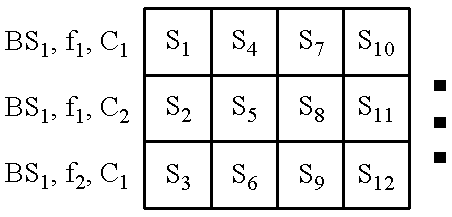
- the encoded symbols are transmitted on a plurality of frequencies and with single code channel per carrier and a set of entirely different encoded symbols are transmitted on different carriers from at least one additional base station as illustrated in Table 5.
- the first base station (BS 1 ) 80 a transmits the encoded symbols S 1 , S 2 and S 3 on frequencies f 1 , f 2 and f 3 and base (BS 2 ) transmits symbols S 4 , S 5 and S 6 on frequencies f 4 , f 5 and f 6 .
- data to be transmitted to remote station 134 is provided to base station controller 200 .
- Base station controller 200 allocates the portions of the data to be transmitted by the base stations in communication with remote station 134 . In the present example, base station controller allocates half of the data to be transmitted by base station 80 a and half of the data to be transmitted by base station 80 b .
- Selector 208 routes encoded symbols S 1 , S 2 and S 3 to base station 80 a and routes S 4 , S 5 and S 6 to base station 80 b .
- Base station 80 a transmits the encoded symbols on frequencies f 1 , f 2 and f 3 and base station 80 b transmits the encoded symbols on frequencies f 4 , f 5 and f 6 transmission is performed as described with respect to the first embodiment.
- the signals from base stations 80 a and 80 b are received at antenna 100 and provided though receiver 102 to down converter 104 .
- Down converter 104 provides the intermediate frequency signals to bank of down converters 110 a - 110 j .
- six secondary downconverters are needed to provide for down conversion of both signals.
- Each of the down converted signal is provided to a corresponding demodulator 118 . If multipath combination is desired or needed, then a single output from one of downconverters 110 is provided to more than one demodulator 118 .
- the data from down converter 110 a is provided to two separate demodulators 118 .
- the data is passed to demultiplexer 128 which reassembles the output data stream such that the encoded symbols are output in the order S 1 , S 2 , S 3 , S 4 , S 5 and S 6 .
- the output sequence is provided to trellis decoder 130 and decoded before the resulting decoded frame is checked by CRC check 132 .
- the encoded symbols are redundantly transmitted from a plurality of base stations on the same frequencies as illustrated in Table 6.
- the first base station (BS 1 ) 80 a transmits the encoded symbol S 1 , on frequencies f 1
- base station (BS 2 ) 80 b redundantly transmits the symbol S 1 on frequency f 1
- base station (BS 3 ) 80 c transmits symbols S 2 and S 3 on frequencies f 4 and f 6
- base station (BS 4 ) 80 d transmits symbols S 2 and S 3 on frequencies f 4 and f 6 .
- data to be transmitted to remote station 134 is provided to base station controller 200 .
- Base station controller redundantly directs the data to be transmitted to each base station in communication with remote station 134 .
- Selector 208 routes encoded symbol S 1 to base station 80 a symbols S 1 to base station 80 b and symbols S 3 and S 4 to base stations 80 c and 80 d .
- Base station 80 a transmits the encoded symbol on frequency f 1 and base station 80 b transmits symbols on frequency f 1
- base station 80 c transmits symbols S 1 and S 2 on frequencies f 4 and f 6 respectively
- base station 80 d transmits symbols S 1 and S 2 on frequencies f 4 and f 6 respectively.
- the signals from base stations 80 a and 80 b are received at antenna 100 and provided though receiver 102 to initial down converter 104 .
- Down converter 104 provides the intermediate frequency signals to bank of down converters 110 a - 110 j .
- only four secondary down converters 110 are needed to provide the down conversion of the four signals.
- Each of the down converted signals is provided to a corresponding demodulator 118 . If multipath combination is desired or needed, then a single output from one of down converters 110 is provided to more than one demodulator 118 . The data from down converter 110 a is provided to two separate demodulators 118 .
- Combiner 127 combines the energies of the received symbols S 1 , S 2 and S 3 from base station 80 a with the energies of the received symbols S 1 , S 2 and S 3 from base station 80 b .
- the data is passed to demultiplexer 128 which reassembles the output data stream such that the encoded symbols are output in the order S 1 , S 2 , S 3 and S 4
- the output sequence is provided to trellis decoder 130 and decoded before the resulting decoded frame is checked by CRC check 132 .
- Another aspect of the present invention is the flexibility to allow a mobile station to search for alternative systems or base stations in the area while remaining in high speed communication.
- base station 80 need not know of the intention of remote station 134 to perform an alternative system search.
- remote station 134 simply sets one or more of local oscillators 110 into a search mode wherein it temporarily stops downconverting data being transmitted to it and searches other frequencies to determine whether they are available to provide reliable communications. During this period remote station 134 depends on the data received on the other frequencies in combination with the error correcting capabilities of trellis decoder 130 to provide an acceptable level of communication.
- mobile station 134 alerts the base station or base stations in communication with it, that it will temporarily place the secondary down converter into a search mode. In response to this message the base or base stations 80 which are in communication with the remote station 134 begin to transmit the data which is provided on channel other than the one temporarily not being received by mobile station 134 at a higher power level. An alternative response of base station 80 to the message from remote station 134 is to begin transmitting to remote station 134 at a lower rate such that the signals that were being received the downconverters that are in search mode are not necessary.
- mobile station 134 informs the base station of its intention to place one or more of down converters 110 into a search mode, and base station 80 redefines the channel allocations such that the data may be maintained at the same level. 5 For example, if base station 80 is transmitting to remote station 134 on one code channel on each of frequencies f 1 , f 2 and f 3 , then if one down converter is placed in search mode such that remote station 134 cannot receive data transmitted on f 1 , then base station 80 will transmit to remote station 134 using an additional code channel on either frequency f 2 or f 3 .
- Another aspect of the present invention is to provide increased reliability and speed in paging remote station 134 .
- a base station 80 attempting to page a remote station 134 does so by providing the paging message on multiple frequencies or from multiple base stations as described previously with respect to traffic data.
- Remote station 134 monitors the paging channel on a plurality of frequencies or from a plurality of base stations. This increases the reliability of paging the remote station 134 through frequency and spatial diversity as described above.
- FIG. 5 illustrates a frequency band allotment of two separate 5 Mhz (or 3.75 Mhz) bands.
- the first group of adjacent carriers is illustrated by frequency bands 250 a , 250 b and 250 c .
- the second group of adjacent carriers is illustrated by carriers 252 a , 252 b and 252 c .
- the receiver structure illustrated in FIG. 6 is capable of receiving information on the three carriers 250 a , 250 b and 250 c and simultaneously searching or receiving data on one of carriers 252 a , 252 b and 252 c.
- the mobile station in which receiver 350 is located is currently receiving data on carriers 250 a , 250 b and 250 c and that the mobile station will search band 252 a to determine whether it is capable of receiving service from the system providing the signal comprising carriers 252 a , 252 b and 252 c .
- data for the mobile station could be provided on carriers 252 a , 252 b or 252 c by simply changing the searching operation to a demodulation operation.
- Signals 250 a , 250 b , 250 c and 252 a are received at antenna 300 and provided through duplexer 302 to low noise amplifier (LNA) 304 .
- the amplified signal is provided to mixer 306 .
- Mixer 306 down converts the signal in accordance with a signal provided by local oscillator 308 which brings the 5 Mhz band consisting of carriers 250 a , 250 b and 250 c down to a MHz wide baseband signal.
- the down converted signal is low pass filtered by filter (BPF 1 ) 314 which is a low pass filter with a 5 Mhz pass band.
- the received signal is also provided to downconverter 310 which brings the signal carried on carrier 252 a down to base band.
- the down converted signal is low pass filtered by filter (BPF 2 ) 316 which is a low pass filter with a 1.23 Mhz pass band.
- the filtered signal from filter 314 is summed with the filtered signal from filter 316 in summer 318 .
- the summed signal is amplified by automatic gain control (AGC) 320 .
- the amplified signal is provided to analog to digital (A/D) converter 322 .
- the digital signals are provided to downconverters 324 a , 324 b and filter (BPF) 328 c .
- Downconverters 324 a and 324 b bring the signals carried on carriers 250 b and 250 c down to base band.
- the signal carried on carriers 250 a and 252 a are already at baseband and is provided directly to filter 328 c .
- the signals 250 a and 252 a act as interference to one another in the demodulation process but given sufficient coding and spreading gain, both the signals can be demodulated. In the present context of searching, it more often than not be the case that no signal is found and in that case the signal degradation will be minimum.
- Downconverter 324 a and downconverter 324 b are driven by local oscillators 326 a and 326 b respectively.
- the down converted signals are provided to filters 328 a and 328 b , which are low pass filters with a 1.228 Mhz pass band.
- filter 328 c is a low pass filter with a 1.228 Mhz pass band.
- the base band signals are then provided to demodulator and searcher 330 which operate as described with respect to demodulator and searcher 116 of FIG. 2 .
- the signal provided through filter 328 c can be demodulated by two demodulators, one to demodulate the signal transmitted from the first system (on carrier 250 a ) and one to demodulate the signal transmitted by the second system (on carrier 252 a ).
- a single demodulator can be time shared demodulating the signal from the first system and at certain intervals demodulating the signal transmitted from the second system.
Abstract
In the present invention, high speed data is provided by transmitting data on multiple carrier frequencies, multiple code channels and/or from multiple base stations. In a first embodiment of the present invention, multiplexed code symbols are transmitted on a plurality of carrier frequencies from the same base station. In second embodiment, code symbols are transmitted on multiple carrier frequencies with at least one corner frequency providing the code symbols is a multiple code channels. In a third embodiment, a subset of the multiplexed code symbols are redundantly provided on a different carrier from at least one additional base station. In a fourth embodiment, multiplexed symbols as transmitted on different carriers from the same base station and are redundantly transmitted on another set of carriers from a different base station. In a fifth embodiment, code symbols are multiplexed onto carriers from a plurality of base stations for increased throughput. In a sixth embodiment, code symbols are transmitted on carriers from a first base station and redundantly provided on at least one additional base station on the same carriers as used by the first base station.
Description
I. Field of the Invention
The present invention relates to communications. More particularly, the present invention relates to a novel and improved method and apparatus for increasing the available data rate to and from a wireless station by multiplexing signals onto multiple carriers, multiple spread spectrum code channels and/or from multiple base stations.
II. Description of the Related Art
The present invention is concerned with transmitting data at rates which are higher than the capacity of a single CDMA channel. Many solutions to this problem have been proposed. One solution is to allocate multiple channels to the users and allow those users to transmit and receive data in parallel on the plurality of channels available to them. Two methods for providing multiple CDMA channels for use by a single user are described in co-pending U.S. Pat. No. 6,005,855, entitled “METHOD AND APPARATUS FOR PROVIDING VARIABLE RATE DATA IN A COMMUNICATIONS SYSTEM USING STATISTICAL MULTIPLEXING”, issued Dec. 21, 1999 and U.S. Pat. No. 5,777,999, entitled “METHOD AND APPARATUS FOR PROVIDING VARIABLE RATE DATA IN A COMMUNICATIONS SYSTEM USING NON-ORTHOGONAL OVERFLOW CHANNELS”, issued Jul. 7,1998, both of which are assigned to the assignee of the present invention and are incorporated by reference herein. In addition, frequency diversity can be obtained by transmitting data over multiple spread spectrum channels that are separated from one another in frequency. A method and apparatus for redundantly transmitting data over multiple CDMA channels is described in U.S. Pat. No. 5,166,951, entitled “HIGH CAPACITY SPREAD SPECTRUM CHANNEL”, which is incorporated by reference herein.
The use of code division multiple access (CDMA) modulation techniques is one of several techniques for facilitating communications in which a large number of system users are present. Other multiple access communication system techniques, such as time division multiple access (TDMA), frequency division multiple access (FDMA) and AM modulation schemes such as amplitude companded single sideband (ACSSB) are known in the art. However, the spread spectrum modulation technique of CDMA has significant advantages over these modulation techniques for multiple access communication systems. The use of CDMA techniques in a multiple access communication system is disclosed in U.S. Pat. No. 4,901,307, entitled “SPREAD SPECTRUM MULTIPLE ACCESS COMMUNICATION SYSTEM USING SATELLITE OR TERRESTRIAL REPEATERS”, assigned to the assignee of the present invention and incorporated by reference herein. The use of CDMA techniques in a multiple access communication system is further disclosed in U.S. Pat. No. 5,103,459, entitled “SYSTEM AND METHOD FOR GENERATING SIGNAL WAVEFORMS IN A CDMA CELLULAR TELEPHONE SYSTEM”, assigned to the assignee of the present invention and incorporated by reference herein.
CDMA by its inherent nature of being a wideband signal offers a form of frequency diversity by spreading the signal energy over a wide bandwidth. Therefore, frequency selective fading affects only a small part of the CDMA signal bandwidth. Space or path diversity is obtained by providing multiple signal paths through simultaneous links from a mobile user through two or more cell-sites. Furthermore, path diversity may be obtained by exploiting the multipath environment through spread spectrum processing by allowing a signal arriving with different propagation delays to be received and processed separately. Examples of the utilization of path diversity are illustrated in copending U.S. Pat. No. 5,101,501 entitled “SOFT HANDOFF IN A CDMA CELLULAR TELEPHONE SYSTEM”, and U.S. Pat. No. 5,109,390 entitled “DIVERSITY RECEIVER IN A CDMA CELLULAR TELEPHONE SYSTEM”, both assigned to the assignee of the present invention and incorporated by reference herein.
The present invention is a novel and improved method and apparatus for the transmission of high speed data in spread spectrum communication systems. In the present invention, high speed data is provided by transmitting data on multiple carrier frequencies, multiple code channels and/or from multiple base stations. In a first embodiment of the present invention, multiplexed code symbols are transmitted on a plurality of carrier frequencies from the same base station. In second embodiment, code symbols are transmitted on multiple carrier frequencies with at least one corner frequency providing the code symbols is a multiple code channels. In a third embodiment, a subset of the multiplexed code symbols are redundantly provided on a different carrier from at least one additional base station. In a fourth embodiment, multiplexed symbols as transmitted on different carriers from the same base station and are redundantly transmitted on another set of carriers from a different base station. In a fifth embodiment, code symbols are multiplexed onto carriers from a plurality of base stations for increased throughput. In a sixth embodiment, code symbols are transmitted on carriers from a first base station and redundantly provided on at least one additional base station on the same carriers as used by the first base station.
The present invention further describes a method wherein a receiver can demodulate data on a plurality of channels and can allocate a demodulator or set of demodulators to search for other available systems, while maintaining the current level of data throughput. In addition the present invention describes a method for receiving multiple paging channels on a plurality of frequencies and code channels.
The features, objects, and advantages of the present invention will become more apparent from the detailed description set forth below when taken in conjunction with the drawings in which like reference characters identify correspondingly throughout and wherein:
FIG. 1 is a block diagram illustrating a base station of the present invention;
FIGS. 2A-2B is a block diagram illustrating a receiver system of the present invention;
FIGS. 3A-3B are illustrations of the frequency bands of the present invention;
FIG. 4 is a block diagram of the wireless network structure for multiplexing the data onto a plurality of base stations;
FIG. 5 is a frequency band diagram to assist in the description of the improved receiver structure illustrated in FIG. 6; and
FIG. 6 is a block diagram of a receiver structure which provides for reduced hardware requirement in the reception of signals transmitted in accordance with the present invention.
I. Single Code Channel Per Frequency Band.
Referring to the figures, FIG. 1 illustrates a base station 80 of the present invention. It shall be noted that in the exemplary embodiment, the transmission occurs from the base station to a remote station, but that this embodiment could be implemented for transmissions from the remote station to the base station. In the first embodiment of the present invention encoded symbols of data are multiplexed onto a plurality of frequencies and transmitted on a single code channel per frequency as illustrated by Table 1 below.
| TABLE 1 |
 |
This implementation provides frequency diversity which can reduce the effects of frequency dependent fading which can degrade the reliability of wireless communication. FIGS. 3A and 3B illustrate the frequency bands for data transmitted using a multiple carrier scheme. Often a service provider will buy a block of bandwidth and divide the band up such that the frequencies are adjacent to one another. This situation is illustrated in FIG. 3A. However the present invention is equally applicable to cases where the bands are not adjacent as is illustrated in FIG. 3B. The spread spectrum technique of CDMA provides inherent frequency diversity and the present invention provides additional frequency diversity through the use of multiple spread spectrum signals transmitted on a plurality of frequencies.
Frames of data to be transmitted by base station 80 is provided to CRC generator 50. CRC generator 50 generates and appends a set of cyclic redundancy check (CRC) bits to the frame of data and in the exemplary embodiment appends a set of tail bits. The frame is then provided to encoder 52. In the exemplary embodiment, encoder 52 is a convolutional encoder. The encoded symbols are provided to multiplexer (MUX) 54. Multiplexer 54 provides the encoded symbols on different outputs in response to a signal from control processor 56. Each output of multiplexer 54 is provided to a corresponding code channel modulator 57 a-57 n. In the first exemplary embodiment, one code channel is allocated for each frequency. Thus, in the first exemplary embodiment the subscript “n” is equal to the subscript “j”.
Each of spreading means 58a-58n is driven by a corresponding Walsh symbol generator 60 a-60 n. It will be understood that Walsh channels are but one method of providing code channels in a CDMA system and that the present invention is equally applicable to other methods of code channel generation. In the exemplary embodiment, each of Walsh symbol generators 60 a-60 n. outputs a spreading sequence that is mutually orthogonal to the remaining spreading sequences. In alternative embodiment, the data can be channeled by means of other modulation techniques, such as phase in the QPSK signal. Moreover, it should be understood that if the signals are transmitted using different PN offsets or on different carriers or from different antennas, then the Walsh sequence spreading need not be orthogonal or even different. In the exemplary embodiment, each of the spread signals from spreading means 58a-58n are provided to a scrambling means 62 a-62 n. Scrambling means 62 a-62 n scramble the data in accordance with scrambling sequence provided by PN generators 64 a-64 n. The method and apparatus for performing orthogonal spreading and for performing scrambling in accordance with a pseudonoise sequence is described in detail in the aforementioned U.S. Pat. Nos. 4,901,307 and 5,103,459.
The modulated data from scramblers 62 a-62 n are provided to multiplexer 65 which directs the data to one of summers 66 a-66 j. In the first embodiment wherein one code channel is allocated for each carrier, multiplexer 65 and summers 66 a-66 j are unnecessary and the code channel modulated data can be provided directly to an upconversion means 68 a-68 j. Each of upconverters 68 a-68 j are driven by a corresponding local oscillator 70 a-70 j which outputs a different frequency sinusoid. The upconverted signals are provided to transmitter 72, which filters and amplifies the signal and provides it for transmission through antenna 74.
FIGS. 2A-2B illustrates the receiver system of the present invention. In the exemplary embodiment, the downconversion of the transmitted signal occurs in two stages. A first downconversion is performed to bring the signal down to an intermediate frequency. Then, a second downconversion is performed to bring the intermediate frequency signal down to baseband. In the present context, baseband refers to the frequency of the spread signal.
Referring to FIGS. 2A-2B, downconverter 104 performs an initial downconversion to a lower frequency, then downconverters 110 a-110 j perform a second downconversion to a lower frequency which is QPSK (Quaternary Phase Shift Keying) demodulated into I and Q signals . Referring to FIG. 3A, the data is provided in three bands. The first signal 150 is transmitted on a frequency of 920 MHz, the second signal 152 is transmitted on as frequency of 922 MHz, and the third signal is transmitted on a frequency of 924 MHz. In order to demodulate data transmitted on these three bands, the data signal might first be down converted by 900 MHz to provide signals at 20 MHz, 22 MHz and 24 MHz to downconverters 110 a-110 j, which complete the downconversion. A first downconverter 104 performs a downconversion of 18 MHz to provide a first low frequency signal at 2 MHz. A second downconverter 110 performs a downconversion of 20 MHz to provide a second low frequency signal at 2 MHz. A third downconverter 110 performs a downconversion of 22 MHz to provide a third low frequency signal at 2 MHz.
Referring to FIG. 3B, the data is again provided in three bands, although the present invention is easily extendible to an arbitrary number of bands. The first signal 160 is transmitted on a frequency of 850 MHz, the second signal 162 is transmitted on a frequency of 920 MHz, and the third signal is transmitted on a frequency of 928 MHz. In order to demodulate data transmitted on these three bands, the signals might first be down converted by 800 MHz and then provided to downconverters 110 a-110 j, which would complete the downconversion to a baseband. A first downconverter 104 performs a downconversion of 48 MHz to provide a first low frequency signal at 2 MHz. A second downconverter 110 performs a downconversion of 68 MHz to provide a second low frequency signal at 2 MHz. A third downconverter 110 performs a downconversion of 76 MHz to provide a third low frequency signal at 2 MHz.
At the receiver, the transmitted signals are received at antenna 100 and provided to receiver (RCVR) 102. Receiver 102 filters and amplifies the received signal and provides it to first downconverter 104. Down converter 104 is driven by local oscillator 106. The down converted signal is then provided to band pass filter 105 which filters the down converted signal to remove artifacts of the down conversion process. Downconverter 104 brings the received signal down to an intermediate frequency. The filtered signal is provide to a bank of second downconverters 110 a-110 j which downconvert the intermediate frequency signal to a low frequency signal. Each of downconverters 110 a-110 j is driven by a corresponding local oscillator 112 a-112 j. In the preferred embodiment, additional flexibility is provided wherein local oscillators 106 and 112 a-112 j are variable frequency synthesizers which output signals with frequencies determined by a control signal provided by control processor 114. The down converted signal are then provided to band pass filters 111 a-111 j, which band pass filter the down converted signals to remove artifacts from the down conversion process.
The low frequency filtered signals from bandpass filters 111 a, 111 b . . . 111 j are provided to QPSK (quaternary Phase Shift Keying) demodulators 228 a, 228 b . . . 228 j respectively. Each QPSK demodulator consists of an I-channel demodulator comprising mixer 212, cosine signal generator (COS) 210 and low pass filter 214 and a Q-channel demodulator comprising a mixer 213, a sine signal generator (which is approximately 90° out of phase with cosine generator 210) and low pass filter 215.
The I and Q channel QPSK demodulated signal are provided to analog to digital converters (A/D) respectively. Analog to digital converts 216 and 217 sample and quantize the QPSK demodulated signals and provide the digital signals to multiplexer 113.
In an alternative embodiment or in addition to the first embodiment, a channel equalizer can be used. Although, many channel equalizer structures are known in the art, a preferred embodiment of the equalizer that operates in conjunction with a CDMA receiver is disclosed in detail in, now U.S. Pat. No. 5,692,006, entitled “ADAPTIVE DESPREADER”, which is assigned to the assignee of the present invention and incorporated by reference herein.
Within each of demodulator 118, the downconverted signal is unscrambled in descrambling means 120 a-120 n. Each of descrambling means 120 a-120 n. is driven by a corresponding pseudonoise generator (PN GEN) 122 a-122 n. Each of the unscrambled signals is provided to a corresponding despreading means 124 a-124 n. It is understood by one skilled in the art that Walsh channels are but one method of providing CDMA channels and that the present invention is equally applicable to other methods of code channel generation and reception. In each of despreading means 124 a-124 n, the pilot channel is despread and the traffic channel is despread. the dot product of the traffic signal with the pilot signal is then performed to yield phase corrected estimates of the traffic data.
The unscrambled signal is provided to despreader 221. Despreader 221 multiplies the signal by a pilot signal which is generated by pilot signal generator (Wpilot). The resultant signal is then low pass filtered to provide a despread pilot signal. The unscrambled signal is also provided to despreading means 222 which multiplies the unscrambled signal with a locally generated traffic Walsh sequence generated by Walsh traffic generators (WT). The resultant signal provided by multiplier 222 is then accumulated by accumulator 224.
The accumulated signal from accumulator 224 and the filtered signal from low pass filter 223 are provided to inner product circuit 225. The design and implementation of inner product circuit 225 is described in detail in U.S. Pat. No. 5,506,865, that was abandoned in favor of a continuation application filed on Nov. 21, 1994, and assigned U.S. Ser. No. 08/343,800, now U.S. Pat. No. 5,506,865 entitled “PILOT CARRIER DOT PRODUCT CIRCUIT”, assigned to the assignee of the present invention and incorporated by reference herein. The despread data is then provided to buffer 226 which provides time alignment of the received signals so that diversity combination may be performed. The buffered signals are then provided to combiner 127 when multipath combination is desirable.
The combined symbol energies are provided to demultiplexer 128, which reorders the symbol stream performing the inverse operation of multiplexer 54 of FIG. 1. The demultiplexed energies are provided to trellis decoder 130. In the exemplary embodiment, trellis decoder 130 is a Viterbi decoder or a MAP decoder, the design of which is known in the art. The decoded data is then provided in frames to CRC check 132 which checks the accuracy of the received frame. If the frame passes the CRC check then the data is provided to the user and if the CRC check fails a frame erasure is declared.
II. Multiple Code Channels Per Carrier for Increased Flexibility and/or Throughput.
In a second embodiment of the present invention, the encoded symbols are provided on a plurality of frequencies and with multiple code channels on at least one of plurality of frequencies as illustrated by Table 2 below.
| TABLE 2 |
 |
It should be noted that the hardware necessary to demodulate a signal comprises the majority of hardware necessary to search a candidate frequency band to determine whether service is available on that frequency. As will be described later herein, the second embodiment can be used in combination with the first embodiment to maintain a constant level of data throughput while allowing a subset of the downconverters to be used to search different frequencies. Thus, when one or more of down converters 110 a-110 j are allocated to the task of searching other frequency bands, the data throughput to the receiver can be maintained by allocating more than one code channel on one of the frequencies being received by remote station 134. In addition, this embodiment provides for ability to provide increased throughput to a mobile station by using available additional capacity on carriers which may not be available on all carriers. Thus, this embodiment assists in both maximizing the throughput to the mobile station and aiding in hard handoff.
In the second embodiment of the present invention, a frame of data to be transmitted by base station 80 is provided to CRC generator 50. CRC generator 50 generates and appends a set of cyclic redundancy check (CRC) bits to the frame of data and appends a set of tail bits. The frame is then provided to encoder 52. In the exemplary embodiment, encoder 52 is a convolutional encoder. The encoded symbols are provided to multiplexer (MUX) 54. Multiplexer 54 provides the encoded symbols of the frame on different outputs based on a signal from control processor 56. Each output of multiplexer 54 is provided to a corresponding code channel modulator 57 a-57 n. In the first exemplary embodiment, more than one code channel is allocated for at least one frequency.
Each of spreading means 58 a-58 n is driven by a corresponding Walsh symbol generator 60 a-60 n. In the exemplary embodiment, each of Walsh symbol generators 60 a-60 n. outputs a spreading sequence that is mutually orthogonal to the remaining spreading sequences. Again, one skilled in the art will understand that the present invention is equally applicable to other forms of code channel generation. In the exemplary embodiment, each of the spread signals from spreading means 58 a-58 n are provided to a corresponding scrambling means 62 a-62 n. Scrambling means 62 a-62 n scramble the data in accordance with scrambling sequence provided by PN generators 64 a-64 n. The method and apparatus for performing orthogonal spreading and for performing scrambling in accordance with a pseudonoise sequence is described in detail in the aforementioned U.S. Pat. Nos. 4,901,307 and 5,103,459.
The modulated data from scramblers 62 a-62 n are provided to multiplexer 65 which directs the data to one of summers 66 a-66 j. In the second embodiment wherein more than one code channel is allocated for at least one frequency band, multiplexer 65 provides the spread data to be transmitted on a single frequency to a summer 66 a-66 j which combines the spread spectrum data for transmission on a single frequency. The summed signals are provided to upconverters 68 a-68 j which combines the spread data for transmission on a single frequency. Each of upconverters 68 a-68 j are driven by a corresponding local oscillator 70 a-70 j each of which outputs a different frequency driving signal. The upconverted signals are provided to transmitter 72, which filters and amplifies the signal and provides it for transmission through antenna 74.
At the receiver, the transmitted signals are received at antenna 100 and provided to receiver (RCVR) 102. Receiver 102 filters and amplifies the received signal and provides it to downconverter 104. Down-converter 104 is driven by local oscillator 106. Downconverter 104 brings the received signal down to an intermediate frequency. The down converted signal is band pass filtered by filter 105 to remove artifacts of the down conversion process. The intermediate frequency signal is provide to the bank of downconverters 110 a-110 j which downconvert the intermediate frequency signal to a low frequency signal. Each of downconverters 110 a-110 j is driven by a corresponding local oscillators 112 a-112 j. The down converted signals are band pass filtered by a band pass filters 111 a-111 j to remove artifacts from the down conversion process. In the preferred embodiment, additional flexibility is provided wherein local oscillators 106 and 112 a-112 j are variable frequency synthesizers which output driving signal with frequencies determined by control signals provided by control processor 114.
The low frequency filtered signals from bandpass filters 111 a, 111 b . . . 111 j are provided to QPSK (quaternary Phase Shift Keying) demodulators 228 a, 228 b . . . 228 j respectively. Each QPSK demodulator consists of an I-channel demodulator comprising mixer 212, cosine signal generator (COS) 210 and low pass filter 214 and a Q-channel demodulator comprising a mixer 213, a sine signal generator (which is approximately 90° out of phase with cosine generator 210) and low pass filter 215.
The I and Q channel QPSK demodulated signal are provided to analog to digital converters (A/D) respectively. Analog to digital converts 216 and 217 sample and quantize the QPSK demodulated signals and provide the digital signals to multiplexer 113.
Within each of demodulators 118 a-118 n, the downconverted signal is unscrambled by descrambling means 120 a-120 n. Each of descrambling means 120 a-120 n. is driven by a pseudonoise generator (PN GEN) 122 a-122 n. The descrambled signals are then provided to despreading means 124 a-124 n. In each of despreading means 124 a-124 n, the pilot channel is despread and the traffic channel is despread. The dot product of the traffic signal with the pilot signal is then performed to yield phase corrected estimates of the traffic data.
The unscrambled signal is provided to despreader 221. Despreader 221 multiplies the signal by a pilot signal which is generated by pilot signal generator (Wpilot). The resultant signal is then low pass filtered to provide a despread pilot signal. The unscrambled signal is also provided to despreading means 222 which multiplies the unscrambled signal with a locally generated traffic Walsh sequence generated by Walsh traffic generators (WT). The resultant signal provided by multiplier 222 is then accumulated by accumulator 224.
The accumulated signal from accumulator 224 and the filtered signal from low pass filter 223 are provided to inner product circuit 225. The design and implementation of inner product circuit 225 is described in detail in U.S. Pat. No. 5,506,865, that was abandoned in favor of a continuation application filed on Nov. 21, 1994, and assigned U.S. Ser. No. 08/343,800, now U.S. Pat. No. 5,506,865 entitled “PILOT CARRIER DOT PRODUCT CIRCUIT”, assigned to the assignee of the present invention and incorporated by reference herein. The despread data is then provided to buffer 226 which provides time alignment of the received signals so that diversity combination may be performed. The buffered signals are then provided to combiner 127 when multipath combination is desirable.
The combined symbol energies are provided to demultiplexer 128, which reorders the symbol stream, performing the inverse operation of multiplexer 54. The demultiplexed symbol energies are provided to trellis decoder 130. In the exemplary embodiment, trellis decoder 130 is a Viterbi decoder or a MAP decoder, the design of which is known in the art. The decoded data is then provided in frames to CRC check 132 which checks the accuracy of the received frame. If the frame passes the CRC check then the data is provided to the user and if the CRC check fails an erasure is declared.
III. Providing Selective Redundancy for Increased Reliability.
In a third embodiment of the present invention, the encoded symbols are transmitted on a plurality of frequencies and with single code channel per carrier and a subset of the encoded symbols are redundantly transmitted on a different carrier from at least one additional base station as illustrated in Table 3.
| TABLE 3 |
 |
Referring to FIG. 4, data to be transmitted to remote station 134 is provided to base station controller 200, which routes the data to the appropriate base station (BS) or base stations 80 a-80 d. The data is provided to buffer 204, which in the exemplary embodiment sends a signal indicative of the amount and priority of data queued for transmission control processor 202. Control processor 202 determines which of base stations 80 a-80 d will be used to transmit the data to remote station 134. In the exemplary embodiment, control processor 202, also determines what frequencies and code channels will be used, though it will be readily understood by one skilled in the art that this function as well as other functions of the base station controller could be performed at base stations 80 a-80 d. Control processor 202 sends a signal to buffer 204 indicating the amount of data to be provided to selector 208. Selector 208, in accordance with a signal from control processor 202 routes the data to the selected ones of base stations 80 a-80 d.
In the this embodiment, the first base station (BS1) 80 a transmits the encoded symbols as described with respect to the first embodiment of the invention wherein symbols are multiplexed onto carriers f1, f2 and fn. In addition to the symbols transmitted by the first base station 80 a, a redundant set of bits are transmitted from base station (BS2) 80 b on a carrier or set of carriers of a frequency different from that used to transmit the bits from base station 80 a. Referring to the example provided in Table 3, encoded symbols S1, S2 and S3 are transmitted on frequencies f1, f2 and f3 from base station 80 a. This operation is performed as described with respect the first embodiment. In addition a second base station 80 b redundantly transmits symbol S2. In the preferred embodiment, symbol S1 is transmitted on frequency f1, which is different from the frequency f2 upon which symbol S2 was transmitted from base station 80 a. This provides for frequency diversity in the transmission of symbol S2 which can improve performance in the face of frequency dependent fading conditions in addition to providing spatial path diversity.
IV. Providing Total Redundancy for Increased Reliability.
In a fourth embodiment of the present invention, the encoded symbols are transmitted on a plurality of frequencies and with single code channel per carrier and all of the encoded symbols are redundantly transmitted on a different carrier from at least one additional base station as illustrated in Table 4.
| TABLE 4 |
 |
Referring to FIG. 4, data to be transmitted to remote station 134 is provided to base station controller 200, which routes the data to the appropriate base station (BS) or base stations 80 a-80 d. The data is provided to buffer 204, which sends a signal indicative of the amount and priority of the data queued to control processor 202. Control processor 202 determines which of base stations 80 a-80 d will be used to transmit the data to remote station 134. In the exemplary embodiment, control processor 202, also determines what frequencies and code channels will be use. Control processor 202 sends a signal to buffer 204 indicating the amount of data to be provided from buffer 204 to selector 208. Selector 208, in accordance with a signal from control processor 202 routes the data to the selected ones of base stations 80 a-80 d.
In the fourth embodiment, the first base station (BS1) 80 a transmits the encoded symbols provided as described with respect to the first embodiment of the invention wherein symbols are multiplexed onto carriers f1, f2 and fn. In addition to the symbols transmitted by the first base station 80 a, a redundant set of all the encoded symbols are transmitted from base station (BS2) 80 b on the same frequencies used to transmit the bits from base station 80 a. Referring to the example provided in Table 4, encoded symbols S1, S2 and S3 are transmitted on frequencies f1, f2 and f3 from base station 80 a. This operation is performed as described with respect the first embodiment. In addition, a second base station 80 b redundantly transmits symbol S1, S2 and S3 on frequencies f1, f2 and f3.
By using the same frequencies to transmit to remote station, remote station 134 can use half the number of downconverters as would be necessary if the frequencies were exclusive sets. Referring back to FIGS. 2A-2B, the signals from base stations 80 a and 80 b are received at antenna 100 and provided through receiver 102 to initial down converter 104. Down converter 104 provides the intermediate frequency signal to bank of down converters 110 a-110 j. In the present example only three such secondary downconverters are needed to provide for demodulation of both signals. So in the example the intermediate frequency signal is provided to three of downconverters 110 a-110 j which perform the down conversion to baseband of data transmitted on frequencies f1, f2 and f3, respectively.
In a first embodiment, the data from down converter 110 a is provided to two separate demodulators 118. One of demodulators 118 demodulates the signal transmitted from base station 80 a and the second demodulates the data transmitted from base station 80 b. More demodulators 118 are employed if diversity combination of multipath signals is desired. The two demodulated signals are then combined in combiner 127 before being provided to demultiplexer 128. The first embodiment provides flexibility so that base stations 80 a to use the same or different code channels for the transmission of the code symbols.
In a second embodiment, the same code channels are used for transmission to remote station 134 from base station 80 a and from base station 80 b and the arrival time of frames at remote station 134 is synchronized. In the second embodiment, the down converted data from downconverter 110 a need only be provided to a single demodulator 118 a and symbol energy combining need only be provided when multipath combination is desired. A channel equalizer can be employed to resolved small difference in arrival time of the redundant signals.
V. Providing Total Redundancy for Increased Reliability.
In a fifth embodiment of the present invention, the encoded symbols are transmitted on a plurality of frequencies and with single code channel per carrier and a set of entirely different encoded symbols are transmitted on different carriers from at least one additional base station as illustrated in Table 5.
| TABLE 5 |
 |
In the this embodiment, the first base station (BS1) 80 a transmits the encoded symbols S1, S2 and S3 on frequencies f1, f2 and f3 and base (BS2) transmits symbols S4, S5 and S6 on frequencies f4, f5 and f6. Referring to FIG. 4, data to be transmitted to remote station 134 is provided to base station controller 200. Base station controller 200 allocates the portions of the data to be transmitted by the base stations in communication with remote station 134. In the present example, base station controller allocates half of the data to be transmitted by base station 80 a and half of the data to be transmitted by base station 80 b. Selector 208 routes encoded symbols S1, S2 and S3 to base station 80 a and routes S4, S5 and S6 to base station 80 b. Base station 80 a transmits the encoded symbols on frequencies f1, f2 and f3 and base station 80 b transmits the encoded symbols on frequencies f4, f5 and f6 transmission is performed as described with respect to the first embodiment.
Referring back to FIG. 2, the signals from base stations 80 a and 80 b are received at antenna 100 and provided though receiver 102 to down converter 104. Down converter 104 provides the intermediate frequency signals to bank of down converters 110 a-110 j. In the present example, six secondary downconverters are needed to provide for down conversion of both signals.
Each of the down converted signal is provided to a corresponding demodulator 118. If multipath combination is desired or needed, then a single output from one of downconverters 110 is provided to more than one demodulator 118. The data from down converter 110 a is provided to two separate demodulators 118. The data is passed to demultiplexer 128 which reassembles the output data stream such that the encoded symbols are output in the order S1, S2, S3, S4, S5 and S6. The output sequence is provided to trellis decoder 130 and decoded before the resulting decoded frame is checked by CRC check 132.
VI. Providing Total Redundancy for Increased Reliability.
In a sixth embodiment of the present invention, the encoded symbols are redundantly transmitted from a plurality of base stations on the same frequencies as illustrated in Table 6.
| TABLE 6 |
 |
In the this embodiment, the first base station (BS1) 80 a transmits the encoded symbol S1, on frequencies f1, base station (BS2) 80 b redundantly transmits the symbol S1 on frequency f1, base station (BS3) 80 c transmits symbols S2 and S3 on frequencies f4 and f6 and base station (BS4) 80 d transmits symbols S2 and S3 on frequencies f4 and f6. Referring to FIG. 4, data to be transmitted to remote station 134 is provided to base station controller 200. Base station controller redundantly directs the data to be transmitted to each base station in communication with remote station 134. Selector 208 routes encoded symbol S1 to base station 80 a symbols S1 to base station 80 b and symbols S3 and S4 to base stations 80 c and 80 d. Base station 80 a transmits the encoded symbol on frequency f1 and base station 80 b transmits symbols on frequency f1, base station 80 c transmits symbols S1 and S2 on frequencies f4 and f6 respectively and base station 80 d transmits symbols S1 and S2 on frequencies f4 and f6 respectively.
Referring back to FIG. 2, the signals from base stations 80 a and 80 b are received at antenna 100 and provided though receiver 102 to initial down converter 104. Down converter 104 provides the intermediate frequency signals to bank of down converters 110 a-110 j. In the present example, only four secondary down converters 110 are needed to provide the down conversion of the four signals.
Each of the down converted signals is provided to a corresponding demodulator 118. If multipath combination is desired or needed, then a single output from one of down converters 110 is provided to more than one demodulator 118. The data from down converter 110 a is provided to two separate demodulators 118. Combiner 127 combines the energies of the received symbols S1, S2 and S3 from base station 80 a with the energies of the received symbols S1, S2 and S3 from base station 80 b. The data is passed to demultiplexer 128 which reassembles the output data stream such that the encoded symbols are output in the order S1, S2, S3 and S4 The output sequence is provided to trellis decoder 130 and decoded before the resulting decoded frame is checked by CRC check 132.
VII. Search for Alternative Systems
Another aspect of the present invention is the flexibility to allow a mobile station to search for alternative systems or base stations in the area while remaining in high speed communication. In a first embodiment for searching for alternative systems, base station 80 need not know of the intention of remote station 134 to perform an alternative system search.
In this first embodiment, remote station 134 simply sets one or more of local oscillators 110 into a search mode wherein it temporarily stops downconverting data being transmitted to it and searches other frequencies to determine whether they are available to provide reliable communications. During this period remote station 134 depends on the data received on the other frequencies in combination with the error correcting capabilities of trellis decoder 130 to provide an acceptable level of communication. In a preferred implementation of the first embodiment, mobile station 134 alerts the base station or base stations in communication with it, that it will temporarily place the secondary down converter into a search mode. In response to this message the base or base stations 80 which are in communication with the remote station 134 begin to transmit the data which is provided on channel other than the one temporarily not being received by mobile station 134 at a higher power level. An alternative response of base station 80 to the message from remote station 134 is to begin transmitting to remote station 134 at a lower rate such that the signals that were being received the downconverters that are in search mode are not necessary.
In a second embodiment for searching alternative system, mobile station 134 informs the base station of its intention to place one or more of down converters 110 into a search mode, and base station 80 redefines the channel allocations such that the data may be maintained at the same level. 5 For example, if base station 80 is transmitting to remote station 134 on one code channel on each of frequencies f1, f2 and f3, then if one down converter is placed in search mode such that remote station 134 cannot receive data transmitted on f1, then base station 80 will transmit to remote station 134 using an additional code channel on either frequency f2 or f3.
VIII. Multiple Paging Channel Reception
Another aspect of the present invention is to provide increased reliability and speed in paging remote station 134. A base station 80 attempting to page a remote station 134, does so by providing the paging message on multiple frequencies or from multiple base stations as described previously with respect to traffic data. Remote station 134 monitors the paging channel on a plurality of frequencies or from a plurality of base stations. This increases the reliability of paging the remote station 134 through frequency and spatial diversity as described above.
IX. Alternative Receiver Structures
FIG. 5 illustrates a frequency band allotment of two separate 5 Mhz (or 3.75 Mhz) bands. The first group of adjacent carriers is illustrated by frequency bands 250 a, 250 b and 250 c. The second group of adjacent carriers is illustrated by carriers 252 a, 252 b and 252 c. The receiver structure illustrated in FIG. 6 is capable of receiving information on the three carriers 250 a, 250 b and 250 c and simultaneously searching or receiving data on one of carriers 252 a, 252 b and 252 c.
To illustrate the operation and advantages of the receiver in FIG. 6, it will be assumed that the mobile station in which receiver 350 is located is currently receiving data on carriers 250 a, 250 b and 250 c and that the mobile station will search band 252 a to determine whether it is capable of receiving service from the system providing the signal comprising carriers 252 a, 252 b and 252 c. It will be understood by one skilled in the art that data for the mobile station could be provided on carriers 252 a, 252 b or 252 c by simply changing the searching operation to a demodulation operation.
The filtered signal from filter 314 is summed with the filtered signal from filter 316 in summer 318. The summed signal is amplified by automatic gain control (AGC) 320. The amplified signal is provided to analog to digital (A/D) converter 322. The digital signals are provided to downconverters 324 a, 324 b and filter (BPF) 328 c. Downconverters 324 a and 324 b bring the signals carried on carriers 250 b and 250 c down to base band. The signal carried on carriers 250 a and 252 a are already at baseband and is provided directly to filter 328 c. The signals 250 a and 252 a act as interference to one another in the demodulation process but given sufficient coding and spreading gain, both the signals can be demodulated. In the present context of searching, it more often than not be the case that no signal is found and in that case the signal degradation will be minimum.
The previous description of the preferred embodiments is provided to enable any person skilled in the art to make or use the present invention. The various modifications to these embodiments will be readily apparent to those skilled in the art, and the generic principles defined herein may be applied to other embodiments without the use of the inventive faculty. Thus, the present invention is not intended to be limited to the embodiments shown herein but is to be accorded the widest scope consistent with the principles and novel features disclosed herein.
Claims (13)
1. A method of transmitting a plurality of symbols, comprising:
multiplexing the symbols onto a plurality of frequencies;
transmitting the multiplexed symbols from a first wireless infrastructure element on at least one code channel per frequency; and
redundantly transmitting a subset of the symbols on at least one of the plurality of frequencies from at least one other wireless infrastructure element.
2. The method of claim 1, wherein the at least one code channel is an orthogonal code channel.
3. The method of claim 1, wherein the subset comprises the entire plurality of symbols.
4. A method of transmitting a plurality of symbols, comprising:
multiplexing the symbols onto a plurality of frequencies;
transmitting the multiplexed symbols from a first wireless infrastructure element on at least one code channel per frequency; and
redundantly transmitting the multiplexed symbols from at least one other wireless infrastructure element on at least one code channel per frequency.
5. The method of claim 4, wherein the at least one code channel is an orthogonal code channel.
6. A method of transmitting a plurality of symbols, comprising:
multiplexing a first subset of the symbols onto a first plurality of frequencies;
transmitting the first subset of multiplexed symbols from a first wireless infrastructure element on at least one code channel per frequency;
multiplexing a second subset of the symbols onto a second plurality of frequencies, wherein the first and second subsets comprise the entire plurality of symbols; and
transmitting the second subset of multiplexed symbols from at least one other wireless infrastructure element on at least one code channel per frequency.
7. The method of claim 6, wherein the at least one code channel is an orthogonal code channel.
8. A method of transmitting a plurality of symbols, comprising:
multiplexing the symbols onto a first plurality of frequencies;
redundantly multiplexing the symbols onto a second plurality of frequencies;
transmitting a first subset of the symbols that was multiplexed onto a first frequency from a first wireless infrastructure element on at least one code channel;
redundantly transmitting the first subset of the symbols that was multiplexed onto the first frequency from a second wireless infrastructure element on at least one code channel;
transmitting a second subset of the symbols that was multiplexed onto a second frequency from a third wireless infrastructure element on at least one code channel;
redundantly transmitting the second subset of the symbols that was multiplexed onto the second frequency from a fourth wireless infrastructure element on at least one code channel;
transmitting a third subset of the symbols that was multiplexed onto a third frequency from the third wireless infrastructure element on at least one code channel; and
redundantly transmitting the third subset of the symbols that was multiplexed onto the third frequency from the fourth wireless infrastructure element on at least one code channel.
9. The method of claim 8, wherein the at least one code channel is an orthogonal code channel.
10. A wireless receiver configured to receive, demodulate, and decode symbols transmitted from a plurality of wireless infrastructure elements in accordance with the method of claim 1.
11. A wireless receiver configured to receive, demodulate, and decode symbols transmitted from a plurality of wireless infrastructure elements in accordance with the method of claim 4.
12. A wireless receiver configured to receive, demodulate, and decode symbols transmitted from a plurality of wireless infrastructure elements in accordance with the method of claim 6.
13. A wireless receiver configured to receive, demodulate, and decode symbols transmitted from a plurality of wireless infrastructure elements in accordance with the method of claim 8.
Priority Applications (2)
| Application Number | Priority Date | Filing Date | Title |
|---|---|---|---|
| US08/929,380 US6215777B1 (en) | 1997-09-15 | 1997-09-15 | Method and apparatus for transmitting and receiving data multiplexed onto multiple code channels, frequencies and base stations |
| US09/686,350 US6359868B1 (en) | 1997-09-15 | 2000-10-10 | Method and apparatus for transmitting and receiving data multiplexed onto multiple code channels, frequencies and base stations |
Applications Claiming Priority (1)
| Application Number | Priority Date | Filing Date | Title |
|---|---|---|---|
| US08/929,380 US6215777B1 (en) | 1997-09-15 | 1997-09-15 | Method and apparatus for transmitting and receiving data multiplexed onto multiple code channels, frequencies and base stations |
Related Child Applications (1)
| Application Number | Title | Priority Date | Filing Date |
|---|---|---|---|
| US09/686,350 Continuation US6359868B1 (en) | 1997-09-15 | 2000-10-10 | Method and apparatus for transmitting and receiving data multiplexed onto multiple code channels, frequencies and base stations |
Publications (1)
| Publication Number | Publication Date |
|---|---|
| US6215777B1 true US6215777B1 (en) | 2001-04-10 |
Family
ID=25457769
Family Applications (2)
| Application Number | Title | Priority Date | Filing Date |
|---|---|---|---|
| US08/929,380 Expired - Lifetime US6215777B1 (en) | 1997-09-15 | 1997-09-15 | Method and apparatus for transmitting and receiving data multiplexed onto multiple code channels, frequencies and base stations |
| US09/686,350 Expired - Lifetime US6359868B1 (en) | 1997-09-15 | 2000-10-10 | Method and apparatus for transmitting and receiving data multiplexed onto multiple code channels, frequencies and base stations |
Family Applications After (1)
| Application Number | Title | Priority Date | Filing Date |
|---|---|---|---|
| US09/686,350 Expired - Lifetime US6359868B1 (en) | 1997-09-15 | 2000-10-10 | Method and apparatus for transmitting and receiving data multiplexed onto multiple code channels, frequencies and base stations |
Country Status (1)
| Country | Link |
|---|---|
| US (2) | US6215777B1 (en) |
Cited By (43)
| Publication number | Priority date | Publication date | Assignee | Title |
|---|---|---|---|---|
| US6308054B2 (en) * | 1999-03-02 | 2001-10-23 | Hitachi, Ltd. | Diversity wireless communication method and its wireless communication apparatus |
| US6359868B1 (en) * | 1997-09-15 | 2002-03-19 | Qualcomm Incorporated | Method and apparatus for transmitting and receiving data multiplexed onto multiple code channels, frequencies and base stations |
| US20020034217A1 (en) * | 1997-02-24 | 2002-03-21 | At&T Wireless Services, Inc. | Adaptive weight update method and system for a discrete multitone spread spectrum communications system |
| US20020122465A1 (en) * | 1997-02-24 | 2002-09-05 | Agee Brian G. | Highly bandwidth-efficient communications |
| US20020136314A1 (en) * | 1997-09-29 | 2002-09-26 | Masahiro Maki | Communication systems, transmitter and receiver |
| US20020191566A1 (en) * | 2001-06-07 | 2002-12-19 | Eliezer Fogel | Method of cellular communication |
| US20030053521A1 (en) * | 2001-09-17 | 2003-03-20 | Xiaojing Huang | System and electronic device for providing a multi-carrier spread spectrum signal |
| US6560209B1 (en) * | 1997-02-06 | 2003-05-06 | At&T Wireless Services, Inc. | Method for frequency division duplex communications |
| US6563807B1 (en) * | 1997-12-30 | 2003-05-13 | Lg Information & Communications, Ltd. | Inter-frequency handoff execution method and apparatus in mobile communication system |
| US6782039B2 (en) | 1997-02-24 | 2004-08-24 | At&T Wireless Services, Inc. | Vertical adaptive antenna array for a discrete multitone spread spectrum communications system |
| US6785300B2 (en) | 1997-02-06 | 2004-08-31 | At&T Wireless Services, Inc. | Delay compensation |
| US20050053165A1 (en) * | 2001-12-06 | 2005-03-10 | Ismail Lakkis | Ultra-wideband communication apparatus and methods |
| US20050053121A1 (en) * | 2001-12-06 | 2005-03-10 | Ismail Lakkis | Ultra-wideband communication apparatus and methods |
| US20050058180A1 (en) * | 2001-12-06 | 2005-03-17 | Ismail Lakkis | Ultra-wideband communication apparatus and methods |
| US20050069020A1 (en) * | 2001-12-06 | 2005-03-31 | Ismail Lakkis | Ultra-wideband communication apparatus and methods |
| US20050152483A1 (en) * | 2001-12-06 | 2005-07-14 | Ismail Lakkis | Systems and methods for implementing path diversity in a wireless communication network |
| US20050233710A1 (en) * | 2001-12-06 | 2005-10-20 | Ismail Lakkis | High data rate transmitter and receiver |
| US6993062B1 (en) * | 1997-11-17 | 2006-01-31 | Samsung Electronics Co., Ltd. | Forward link device of multicarrier communication system and method for realizing the same |
| US7027484B1 (en) * | 1998-07-10 | 2006-04-11 | Qualcomm Incorporated | Method and apparatus for transmitting and receiving high speed data using code division multiple access channels |
| US7031371B1 (en) * | 2000-09-25 | 2006-04-18 | Lakkis Ismail A | CDMA/TDMA communication method and apparatus for wireless communication using cyclic spreading codes |
| WO2006041681A2 (en) * | 2004-10-08 | 2006-04-20 | Pulse-Link, Inc. | Ultra-wideband communication systems and methods |
| US20070077886A1 (en) * | 1999-04-15 | 2007-04-05 | Lundby Stein S | Interleaver and deinterleaver for use in a diversity transmission communication system |
| US20070268843A1 (en) * | 2006-05-22 | 2007-11-22 | Viasat, Inc. | Segmented Code Division Multiple Access |
| US20070268959A1 (en) * | 2006-05-16 | 2007-11-22 | Lucent Technologies Inc. | Scalable spectrum CDMA communication systems and methods with dynamic orthogonal code allocation |
| US20080008234A1 (en) * | 2001-12-06 | 2008-01-10 | Ismail Lakkis | Systems and methods for equalization of received signals in a wireless communication network |
| US20080043654A1 (en) * | 2001-12-06 | 2008-02-21 | Lakkis Ismail A | Systems and methods for wireless communication over a wide bandwidth channel using a plurality of sub-channels |
| US20080056333A1 (en) * | 2001-12-06 | 2008-03-06 | Ismail Lakkis | Ultra-wideband communication apparatus and methods |
| US20080056332A1 (en) * | 2001-12-06 | 2008-03-06 | Ismail Lakkis | Ultra-wideband communication systems and methods |
| US20080056186A1 (en) * | 2001-12-06 | 2008-03-06 | Ismail Lakkis | Ultra-wideband communication systems and methods |
| US20080109696A1 (en) * | 2001-12-06 | 2008-05-08 | Ismail Lakkis | Systems and methods for forward error correction in a wireless communication network |
| US20080107199A1 (en) * | 2001-12-06 | 2008-05-08 | Ismail Lakkis | Systems and methods for recovering bandwidth in a wireless communication network |
| US7403576B2 (en) | 2001-12-06 | 2008-07-22 | Pulse-Link, Inc. | Systems and methods for receiving data in a wireless communication network |
| US20090245171A1 (en) * | 2006-04-26 | 2009-10-01 | Mitsubishi Electric Corporation | Wireless communication system and wireless communication apparatus |
| US20110135308A1 (en) * | 2009-12-09 | 2011-06-09 | Luigi Tarlazzi | Distributed antenna system for mimo signals |
| US20110201368A1 (en) * | 2010-02-12 | 2011-08-18 | Pier Faccin | Distributed antenna system for mimo communications |
| US9184962B2 (en) | 2009-12-09 | 2015-11-10 | Andrew Wireless Systems Gmbh | Distributed antenna system for MIMO signals |
| US9231670B2 (en) | 2010-10-01 | 2016-01-05 | Commscope Technologies Llc | Distributed antenna system for MIMO signals |
| USRE46477E1 (en) * | 1998-05-15 | 2017-07-11 | Sony Corporation | Transmitter and transmitting method increasing the flexibility of code assignment |
| RU2691733C1 (en) * | 2018-10-15 | 2019-06-18 | Акционерное общество "Концерн "Созвездие" | Device for generation and processing of broadband signals |
| RU2714300C1 (en) * | 2019-02-06 | 2020-02-14 | Акционерное общество "Концерн "Созвездие" | Method for spreading signals spectrum |
| RU2734230C1 (en) * | 2020-02-14 | 2020-10-13 | Акционерное общество "Концерн "Созвездие" | Method of forming noise-like phase-shift keyed signals |
| US11050594B2 (en) * | 2019-12-03 | 2021-06-29 | Harris Global Communications, Inc. | Communications system having multiple spread carriers and associated methods |
| RU2792089C1 (en) * | 2022-03-16 | 2023-03-16 | Федеральное государственное казенное военное образовательное учреждение высшего образования "Рязанское гвардейское высшее воздушно-десантное ордена Суворова дважды Краснознаменное командное училище имени генерала армии В.Ф. Маргелова" Министерства обороны Российской Федерации | Method of transmitting radio signals in the mode of pseudorandom adjustment of the operating frequency |
Families Citing this family (14)
| Publication number | Priority date | Publication date | Assignee | Title |
|---|---|---|---|---|
| KR100293412B1 (en) * | 1997-12-31 | 2001-07-12 | 박종섭 | Pico-cell indicator and method for registering cells of mobile terminal using the same |
| US6542492B1 (en) * | 1999-05-28 | 2003-04-01 | Koninklijke Philips Electronics N.V. | Method and system of initializing state metrics for traffic, paging, and sync channels to enhance Viterbi decoder performance |
| KR100354337B1 (en) * | 1999-12-04 | 2002-09-28 | 한국과학기술원 | Transmission and Receiving using Spreading Modulation for Spread Spectrum Communications and thereof Apparatus |
| US6735240B1 (en) * | 2000-11-21 | 2004-05-11 | Qualcomm, Incorporated | System and method of deskew buffering signals |
| US7181162B2 (en) * | 2000-12-12 | 2007-02-20 | The Directv Group, Inc. | Communication system using multiple link terminals |
| US7103317B2 (en) * | 2000-12-12 | 2006-09-05 | The Directv Group, Inc. | Communication system using multiple link terminals for aircraft |
| US7400857B2 (en) * | 2000-12-12 | 2008-07-15 | The Directv Group, Inc. | Communication system using multiple link terminals |
| US20020073437A1 (en) * | 2000-12-12 | 2002-06-13 | Hughes Electronics Corporation | Television distribution system using multiple links |
| US6952580B2 (en) * | 2000-12-12 | 2005-10-04 | The Directv Group, Inc. | Multiple link internet protocol mobile communications system and method therefor |
| US7068616B2 (en) * | 2001-02-05 | 2006-06-27 | The Directv Group, Inc. | Multiple dynamic connectivity for satellite communications systems |
| JP3564108B2 (en) * | 2002-03-08 | 2004-09-08 | イビデン産業株式会社 | Wire spread spectrum communication apparatus, communication method thereof, and wire spread spectrum communication system |
| KR100595584B1 (en) * | 2003-02-12 | 2006-07-03 | 엘지전자 주식회사 | Wireless transceiver |
| WO2006050181A2 (en) * | 2004-10-29 | 2006-05-11 | Ohio University | Spectrally shaped generalized multitone direct sequence spread spectrum modulation |
| US8290371B2 (en) * | 2008-09-19 | 2012-10-16 | Telcordia Technologies, Inc. | OCDM-based all optical multi-level security |
Citations (32)
| Publication number | Priority date | Publication date | Assignee | Title |
|---|---|---|---|---|
| US3819872A (en) | 1972-07-10 | 1974-06-25 | Bell Telephone Labor Inc | Mobile telephone cellular switching system |
| US4004224A (en) | 1972-01-17 | 1977-01-18 | Siemens Aktiengesellschaft | Method for fade correction of communication transmission over directional radio paths |
| US4112257A (en) | 1977-03-24 | 1978-09-05 | Frost Edward G | Comprehensive automatic mobile radio telephone system |
| US4123718A (en) | 1970-09-30 | 1978-10-31 | Siemens Aktiengesellschaft | SSMA receiver with synchronous demodulation and variable gain control |
| US4222115A (en) | 1978-03-13 | 1980-09-09 | Purdue Research Foundation | Spread spectrum apparatus for cellular mobile communication systems |
| US4309771A (en) | 1979-07-02 | 1982-01-05 | Farinon Corporation | Digital radio transmission system |
| US4398063A (en) | 1980-10-24 | 1983-08-09 | Hass Ronald J | Mobile telephone interoffice handoff limiting method and apparatus |
| US4475010A (en) | 1983-05-05 | 1984-10-02 | At&T Bell Laboratories | High density cellular mobile radio communications |
| US4495648A (en) | 1982-12-27 | 1985-01-22 | At&T Bell Laboratories | Transmitter power control circuit |
| US4580262A (en) | 1982-12-08 | 1986-04-01 | Racal-Ses Limited | Radio systems |
| US4608711A (en) | 1984-06-21 | 1986-08-26 | Itt Corporation | Cellular mobile radio hand-off utilizing voice channel |
| US4641322A (en) | 1983-10-18 | 1987-02-03 | Nec Corporation | System for carrying out spread spectrum communication through an electric power line |
| US4672658A (en) | 1985-10-16 | 1987-06-09 | At&T Company And At&T Bell Laboratories | Spread spectrum wireless PBX |
| US4718081A (en) | 1986-11-13 | 1988-01-05 | General Electric Company | Method and apparatus for reducing handoff errors in a cellular radio telephone communications system |
| US4765753A (en) | 1986-03-08 | 1988-08-23 | U.S. Philips Corporation | Method and apparatus for handing-over a radio connection from one radio cell to another radio cell of a digital radio transmission system |
| US4811421A (en) | 1986-03-14 | 1989-03-07 | Christophe Havel | Transmission power control device in a radio communication transmitting/receiving station |
| EP0421535A1 (en) | 1989-10-03 | 1991-04-10 | Koninklijke KPN N.V. | Method for transferring, between two switching exchanges for mobile services, the handling of an active connection with a mobile terminal |
| US5054110A (en) | 1989-12-29 | 1991-10-01 | Motorola, Inc. | Multi-site dispatching system cell registration |
| US5056109A (en) | 1989-11-07 | 1991-10-08 | Qualcomm, Inc. | Method and apparatus for controlling transmission power in a cdma cellular mobile telephone system |
| US5101501A (en) | 1989-11-07 | 1992-03-31 | Qualcomm Incorporated | Method and system for providing a soft handoff in communications in a cdma cellular telephone system |
| US5103459A (en) | 1990-06-25 | 1992-04-07 | Qualcomm Incorporated | System and method for generating signal waveforms in a cdma cellular telephone system |
| US5109390A (en) | 1989-11-07 | 1992-04-28 | Qualcomm Incorporated | Diversity receiver in a cdma cellular telephone system |
| US5109528A (en) | 1988-06-14 | 1992-04-28 | Telefonaktiebolaget L M Ericsson | Handover method for mobile radio system |
| US5127100A (en) | 1989-04-27 | 1992-06-30 | Motorola, Inc. | Digital radio communication system and two way radio |
| US5164958A (en) | 1991-05-22 | 1992-11-17 | Cylink Corporation | Spread spectrum cellular handoff method |
| US5179571A (en) | 1991-07-10 | 1993-01-12 | Scs Mobilecom, Inc. | Spread spectrum cellular handoff apparatus and method |
| US5235615A (en) | 1991-05-22 | 1993-08-10 | Cylink Corporation | Spread spectrum method |
| US5265119A (en) | 1989-11-07 | 1993-11-23 | Qualcomm Incorporated | Method and apparatus for controlling transmission power in a CDMA cellular mobile telephone system |
| US5267261A (en) | 1992-03-05 | 1993-11-30 | Qualcomm Incorporated | Mobile station assisted soft handoff in a CDMA cellular communications system |
| US5267262A (en) | 1989-11-07 | 1993-11-30 | Qualcomm Incorporated | Transmitter power control system |
| US5327577A (en) | 1988-06-14 | 1994-07-05 | Telefonaktiebolaget L M Ericsson | Handover method for mobile radio system |
| US5504783A (en) * | 1992-11-20 | 1996-04-02 | Ntt Mobile Communication Network Inc. | Frequency diversity transmitter and receiver |
Family Cites Families (1)
| Publication number | Priority date | Publication date | Assignee | Title |
|---|---|---|---|---|
| US6215777B1 (en) * | 1997-09-15 | 2001-04-10 | Qualcomm Inc. | Method and apparatus for transmitting and receiving data multiplexed onto multiple code channels, frequencies and base stations |
-
1997
- 1997-09-15 US US08/929,380 patent/US6215777B1/en not_active Expired - Lifetime
-
2000
- 2000-10-10 US US09/686,350 patent/US6359868B1/en not_active Expired - Lifetime
Patent Citations (34)
| Publication number | Priority date | Publication date | Assignee | Title |
|---|---|---|---|---|
| US4123718A (en) | 1970-09-30 | 1978-10-31 | Siemens Aktiengesellschaft | SSMA receiver with synchronous demodulation and variable gain control |
| US4004224A (en) | 1972-01-17 | 1977-01-18 | Siemens Aktiengesellschaft | Method for fade correction of communication transmission over directional radio paths |
| US3819872A (en) | 1972-07-10 | 1974-06-25 | Bell Telephone Labor Inc | Mobile telephone cellular switching system |
| US4112257A (en) | 1977-03-24 | 1978-09-05 | Frost Edward G | Comprehensive automatic mobile radio telephone system |
| US4222115A (en) | 1978-03-13 | 1980-09-09 | Purdue Research Foundation | Spread spectrum apparatus for cellular mobile communication systems |
| US4309771A (en) | 1979-07-02 | 1982-01-05 | Farinon Corporation | Digital radio transmission system |
| US4398063A (en) | 1980-10-24 | 1983-08-09 | Hass Ronald J | Mobile telephone interoffice handoff limiting method and apparatus |
| US4580262A (en) | 1982-12-08 | 1986-04-01 | Racal-Ses Limited | Radio systems |
| US4495648A (en) | 1982-12-27 | 1985-01-22 | At&T Bell Laboratories | Transmitter power control circuit |
| US4475010A (en) | 1983-05-05 | 1984-10-02 | At&T Bell Laboratories | High density cellular mobile radio communications |
| US4641322A (en) | 1983-10-18 | 1987-02-03 | Nec Corporation | System for carrying out spread spectrum communication through an electric power line |
| US4608711A (en) | 1984-06-21 | 1986-08-26 | Itt Corporation | Cellular mobile radio hand-off utilizing voice channel |
| US4672658A (en) | 1985-10-16 | 1987-06-09 | At&T Company And At&T Bell Laboratories | Spread spectrum wireless PBX |
| US4765753A (en) | 1986-03-08 | 1988-08-23 | U.S. Philips Corporation | Method and apparatus for handing-over a radio connection from one radio cell to another radio cell of a digital radio transmission system |
| US4811421A (en) | 1986-03-14 | 1989-03-07 | Christophe Havel | Transmission power control device in a radio communication transmitting/receiving station |
| US4718081A (en) | 1986-11-13 | 1988-01-05 | General Electric Company | Method and apparatus for reducing handoff errors in a cellular radio telephone communications system |
| US5109528A (en) | 1988-06-14 | 1992-04-28 | Telefonaktiebolaget L M Ericsson | Handover method for mobile radio system |
| US5327577A (en) | 1988-06-14 | 1994-07-05 | Telefonaktiebolaget L M Ericsson | Handover method for mobile radio system |
| US5127100A (en) | 1989-04-27 | 1992-06-30 | Motorola, Inc. | Digital radio communication system and two way radio |
| EP0421535A1 (en) | 1989-10-03 | 1991-04-10 | Koninklijke KPN N.V. | Method for transferring, between two switching exchanges for mobile services, the handling of an active connection with a mobile terminal |
| US5267262A (en) | 1989-11-07 | 1993-11-30 | Qualcomm Incorporated | Transmitter power control system |
| US5101501A (en) | 1989-11-07 | 1992-03-31 | Qualcomm Incorporated | Method and system for providing a soft handoff in communications in a cdma cellular telephone system |
| US5056109A (en) | 1989-11-07 | 1991-10-08 | Qualcomm, Inc. | Method and apparatus for controlling transmission power in a cdma cellular mobile telephone system |
| US5109390A (en) | 1989-11-07 | 1992-04-28 | Qualcomm Incorporated | Diversity receiver in a cdma cellular telephone system |
| US5265119A (en) | 1989-11-07 | 1993-11-23 | Qualcomm Incorporated | Method and apparatus for controlling transmission power in a CDMA cellular mobile telephone system |
| US5054110A (en) | 1989-12-29 | 1991-10-01 | Motorola, Inc. | Multi-site dispatching system cell registration |
| US5103459A (en) | 1990-06-25 | 1992-04-07 | Qualcomm Incorporated | System and method for generating signal waveforms in a cdma cellular telephone system |
| US5103459B1 (en) | 1990-06-25 | 1999-07-06 | Qualcomm Inc | System and method for generating signal waveforms in a cdma cellular telephone system |
| US5309474A (en) | 1990-06-25 | 1994-05-03 | Qualcomm Incorporated | System and method for generating signal waveforms in a CDMA cellular telephone system |
| US5235615A (en) | 1991-05-22 | 1993-08-10 | Cylink Corporation | Spread spectrum method |
| US5164958A (en) | 1991-05-22 | 1992-11-17 | Cylink Corporation | Spread spectrum cellular handoff method |
| US5179571A (en) | 1991-07-10 | 1993-01-12 | Scs Mobilecom, Inc. | Spread spectrum cellular handoff apparatus and method |
| US5267261A (en) | 1992-03-05 | 1993-11-30 | Qualcomm Incorporated | Mobile station assisted soft handoff in a CDMA cellular communications system |
| US5504783A (en) * | 1992-11-20 | 1996-04-02 | Ntt Mobile Communication Network Inc. | Frequency diversity transmitter and receiver |
Cited By (98)
| Publication number | Priority date | Publication date | Assignee | Title |
|---|---|---|---|---|
| US6785300B2 (en) | 1997-02-06 | 2004-08-31 | At&T Wireless Services, Inc. | Delay compensation |
| US8305990B2 (en) | 1997-02-06 | 2012-11-06 | At&T Mobility Ii Llc | Method for frequency division duplex communications |
| US8693432B2 (en) | 1997-02-06 | 2014-04-08 | At&T Mobility Ii Llc | Method for frequency division duplex communications |
| US9088388B2 (en) | 1997-02-06 | 2015-07-21 | At&T Mobility Ii Llc | Method for frequency division duplex communications |
| US7460561B2 (en) | 1997-02-06 | 2008-12-02 | Clearwire Corporation | Delay compensation |
| US20110222526A1 (en) * | 1997-02-06 | 2011-09-15 | Siavash Alamouti | Method for frequency division duplex communications |
| US20080298339A1 (en) * | 1997-02-06 | 2008-12-04 | Siavash Alamouti | Method for frequency division duplex communications |
| US6853629B2 (en) | 1997-02-06 | 2005-02-08 | Cingular Wireless Ii, Llc | Method for frequency division duplex communications |
| US7983217B2 (en) | 1997-02-06 | 2011-07-19 | At&T Mobility Ii Llc | Method for frequency division duplex communications |
| US6560209B1 (en) * | 1997-02-06 | 2003-05-06 | At&T Wireless Services, Inc. | Method for frequency division duplex communications |
| US20040264549A1 (en) * | 1997-02-06 | 2004-12-30 | Elliott Hoole | Delay compensation |
| US20020122465A1 (en) * | 1997-02-24 | 2002-09-05 | Agee Brian G. | Highly bandwidth-efficient communications |
| US20050002440A1 (en) * | 1997-02-24 | 2005-01-06 | Siavash Alamouti | Vertical adaptive antenna array for a discrete multitone spread spectrum communications system |
| US7061969B2 (en) | 1997-02-24 | 2006-06-13 | Cingular Wireless Ii, Llc | Vertical adaptive antenna array for a discrete multitone spread spectrum communication system |
| US20060193373A1 (en) * | 1997-02-24 | 2006-08-31 | Agee Brian G | Highly bandwidth-efficient communications |
| US20020034217A1 (en) * | 1997-02-24 | 2002-03-21 | At&T Wireless Services, Inc. | Adaptive weight update method and system for a discrete multitone spread spectrum communications system |
| US7106781B2 (en) | 1997-02-24 | 2006-09-12 | Cingular Wireless Ii, Llc | Highly bandwidth-efficient communications |
| US6782039B2 (en) | 1997-02-24 | 2004-08-24 | At&T Wireless Services, Inc. | Vertical adaptive antenna array for a discrete multitone spread spectrum communications system |
| US6975668B2 (en) | 1997-02-24 | 2005-12-13 | Cingular Wireless Ii, Llc | Adaptive weight update method and system for a discrete multitone spread spectrum communications system |
| US7149238B2 (en) | 1997-02-24 | 2006-12-12 | Cingular Wireless Ii, Llc | Highly bandwidth-efficient communications |
| US6359868B1 (en) * | 1997-09-15 | 2002-03-19 | Qualcomm Incorporated | Method and apparatus for transmitting and receiving data multiplexed onto multiple code channels, frequencies and base stations |
| US6507622B2 (en) * | 1997-09-29 | 2003-01-14 | Matsushita Electric Industrial Co., Ltd. | Communication systems, sender and receiver |
| US20020136314A1 (en) * | 1997-09-29 | 2002-09-26 | Masahiro Maki | Communication systems, transmitter and receiver |
| US6993062B1 (en) * | 1997-11-17 | 2006-01-31 | Samsung Electronics Co., Ltd. | Forward link device of multicarrier communication system and method for realizing the same |
| US6563807B1 (en) * | 1997-12-30 | 2003-05-13 | Lg Information & Communications, Ltd. | Inter-frequency handoff execution method and apparatus in mobile communication system |
| USRE46477E1 (en) * | 1998-05-15 | 2017-07-11 | Sony Corporation | Transmitter and transmitting method increasing the flexibility of code assignment |
| US20090252141A1 (en) * | 1998-07-10 | 2009-10-08 | Qualcomm Incorporated | Method and Apparatus for Transmitting and Receiving High Speed Data Using Code Division Multiple Access Channels |
| US8345728B2 (en) | 1998-07-10 | 2013-01-01 | Qualcomm Incorporated | Method and apparatus for transmitting and receiving high speed data using code division multiple access channels |
| US8040936B2 (en) | 1998-07-10 | 2011-10-18 | Qualcomm, Incorporated | Method and apparatus for transmitting and receiving high speed data using code division multiple access channels |
| US7027484B1 (en) * | 1998-07-10 | 2006-04-11 | Qualcomm Incorporated | Method and apparatus for transmitting and receiving high speed data using code division multiple access channels |
| US7675961B2 (en) | 1998-07-10 | 2010-03-09 | Qualcomm Incorporated | Method and apparatus for transmitting and receiving high speed data using code division multiple access channels |
| US20090316761A1 (en) * | 1998-07-10 | 2009-12-24 | Qualcomm Incorporated | Method and Apparatus For Transmitting and Receiving High Speed Data Using Code Division Multiple Access Channels |
| US6456830B2 (en) * | 1999-03-02 | 2002-09-24 | Hitachi, Ltd. | Diversity wireless communication method and its wireless communication apparatus |
| US6308054B2 (en) * | 1999-03-02 | 2001-10-23 | Hitachi, Ltd. | Diversity wireless communication method and its wireless communication apparatus |
| EP1855392A2 (en) | 1999-04-15 | 2007-11-14 | QUALCOMM Incorporated | Interleaver and deinterleaver for use in a diversity transmission communication system |
| US20070077886A1 (en) * | 1999-04-15 | 2007-04-05 | Lundby Stein S | Interleaver and deinterleaver for use in a diversity transmission communication system |
| US20080225963A1 (en) * | 2000-09-25 | 2008-09-18 | Ismail Lakkis | Ultra-wideband communication systems and methods |
| US7031371B1 (en) * | 2000-09-25 | 2006-04-18 | Lakkis Ismail A | CDMA/TDMA communication method and apparatus for wireless communication using cyclic spreading codes |
| US20020191566A1 (en) * | 2001-06-07 | 2002-12-19 | Eliezer Fogel | Method of cellular communication |
| US20030053521A1 (en) * | 2001-09-17 | 2003-03-20 | Xiaojing Huang | System and electronic device for providing a multi-carrier spread spectrum signal |
| US10700754B2 (en) | 2001-11-30 | 2020-06-30 | Andrew Wireless Systems Gmbh | Distributed antenna system for MIMO signals |
| US20080109696A1 (en) * | 2001-12-06 | 2008-05-08 | Ismail Lakkis | Systems and methods for forward error correction in a wireless communication network |
| US20080049827A1 (en) * | 2001-12-06 | 2008-02-28 | Ismail Lakkis | Systems and methods for implementing path diversity in a wireless communication network |
| US20080049652A1 (en) * | 2001-12-06 | 2008-02-28 | Lakkis Ismail A | Systems and methods for wireless communication over a wide bandwidth channel using a plurality of sub-channels |
| US20080056333A1 (en) * | 2001-12-06 | 2008-03-06 | Ismail Lakkis | Ultra-wideband communication apparatus and methods |
| US20080056332A1 (en) * | 2001-12-06 | 2008-03-06 | Ismail Lakkis | Ultra-wideband communication systems and methods |
| US20080056186A1 (en) * | 2001-12-06 | 2008-03-06 | Ismail Lakkis | Ultra-wideband communication systems and methods |
| US20080069256A1 (en) * | 2001-12-06 | 2008-03-20 | Ismail Lakkis | Ultra-wideband communication apparatus and methods |
| US20080043653A1 (en) * | 2001-12-06 | 2008-02-21 | Lakkis Ismail A | Systems and methods for wireless communication over a wide bandwidth channel using a plurality of sub-channels |
| US20080107199A1 (en) * | 2001-12-06 | 2008-05-08 | Ismail Lakkis | Systems and methods for recovering bandwidth in a wireless communication network |
| US20050053165A1 (en) * | 2001-12-06 | 2005-03-10 | Ismail Lakkis | Ultra-wideband communication apparatus and methods |
| US7391815B2 (en) | 2001-12-06 | 2008-06-24 | Pulse-Link, Inc. | Systems and methods to recover bandwidth in a communication system |
| US7403576B2 (en) | 2001-12-06 | 2008-07-22 | Pulse-Link, Inc. | Systems and methods for receiving data in a wireless communication network |
| US7406647B2 (en) | 2001-12-06 | 2008-07-29 | Pulse-Link, Inc. | Systems and methods for forward error correction in a wireless communication network |
| US20080043654A1 (en) * | 2001-12-06 | 2008-02-21 | Lakkis Ismail A | Systems and methods for wireless communication over a wide bandwidth channel using a plurality of sub-channels |
| US7450637B2 (en) | 2001-12-06 | 2008-11-11 | Pulse-Link, Inc. | Ultra-wideband communication apparatus and methods |
| US20050053121A1 (en) * | 2001-12-06 | 2005-03-10 | Ismail Lakkis | Ultra-wideband communication apparatus and methods |
| US20080008234A1 (en) * | 2001-12-06 | 2008-01-10 | Ismail Lakkis | Systems and methods for equalization of received signals in a wireless communication network |
| US7483483B2 (en) | 2001-12-06 | 2009-01-27 | Pulse-Link, Inc. | Ultra-wideband communication apparatus and methods |
| US20050058180A1 (en) * | 2001-12-06 | 2005-03-17 | Ismail Lakkis | Ultra-wideband communication apparatus and methods |
| US8744389B2 (en) | 2001-12-06 | 2014-06-03 | Intellectual Ventures Holding 73 Llc | High data rate transmitter and receiver |
| US20050069020A1 (en) * | 2001-12-06 | 2005-03-31 | Ismail Lakkis | Ultra-wideband communication apparatus and methods |
| US8532586B2 (en) | 2001-12-06 | 2013-09-10 | Intellectual Ventures Holding 73 Llc | High data rate transmitter and receiver |
| US7929596B2 (en) | 2001-12-06 | 2011-04-19 | Pulse-Link, Inc. | Ultra-wideband communication apparatus and methods |
| US20050152483A1 (en) * | 2001-12-06 | 2005-07-14 | Ismail Lakkis | Systems and methods for implementing path diversity in a wireless communication network |
| US20050233710A1 (en) * | 2001-12-06 | 2005-10-20 | Ismail Lakkis | High data rate transmitter and receiver |
| US8045935B2 (en) | 2001-12-06 | 2011-10-25 | Pulse-Link, Inc. | High data rate transmitter and receiver |
| WO2006041681A2 (en) * | 2004-10-08 | 2006-04-20 | Pulse-Link, Inc. | Ultra-wideband communication systems and methods |
| WO2006041681A3 (en) * | 2004-10-08 | 2006-12-07 | Pulse Link Inc | Ultra-wideband communication systems and methods |
| US8036162B2 (en) * | 2006-04-26 | 2011-10-11 | Mitsubishi Electric Corporation | Wireless communication system and wireless communication device |
| US20090245171A1 (en) * | 2006-04-26 | 2009-10-01 | Mitsubishi Electric Corporation | Wireless communication system and wireless communication apparatus |
| US20070268959A1 (en) * | 2006-05-16 | 2007-11-22 | Lucent Technologies Inc. | Scalable spectrum CDMA communication systems and methods with dynamic orthogonal code allocation |
| WO2007136529A3 (en) * | 2006-05-16 | 2008-01-31 | Lucent Technologies Inc | Scalable spectrum cdma communication systems and methods with dynamic orthogonal code allocation |
| US8081686B2 (en) | 2006-05-16 | 2011-12-20 | Alcatel Lucent | Scalable spectrum CDMA communication systems and methods with dynamic orthogonal code allocation |
| CN101444029B (en) * | 2006-05-16 | 2012-05-23 | 卢森特技术有限公司 | Scalable spectrum CDMA communication systems and methods with dynamic orthogonal code allocation |
| WO2007136529A2 (en) * | 2006-05-16 | 2007-11-29 | Lucent Technologies Inc. | Scalable spectrum cdma communication systems and methods with dynamic orthogonal code allocation |
| US20070268843A1 (en) * | 2006-05-22 | 2007-11-22 | Viasat, Inc. | Segmented Code Division Multiple Access |
| WO2007137270A2 (en) * | 2006-05-22 | 2007-11-29 | Viasat, Inc. | Segmented code division multiple access |
| WO2007137270A3 (en) * | 2006-05-22 | 2008-06-05 | Viasat Inc | Segmented code division multiple access |
| US8396368B2 (en) | 2009-12-09 | 2013-03-12 | Andrew Llc | Distributed antenna system for MIMO signals |
| US20110135308A1 (en) * | 2009-12-09 | 2011-06-09 | Luigi Tarlazzi | Distributed antenna system for mimo signals |
| US9184962B2 (en) | 2009-12-09 | 2015-11-10 | Andrew Wireless Systems Gmbh | Distributed antenna system for MIMO signals |
| US9246559B2 (en) | 2009-12-09 | 2016-01-26 | Andrew Wireless Systems Gmbh | Distributed antenna system for MIMO signals |
| US9787385B2 (en) | 2009-12-09 | 2017-10-10 | Andrew Wireless Systems Gmbh | Distributed antenna system for MIMO signals |
| US8744504B2 (en) | 2010-02-12 | 2014-06-03 | Andrew Llc | Distributed antenna system for MIMO communications |
| US10644761B2 (en) | 2010-02-12 | 2020-05-05 | Andrew Wireless Systems Gmbh | Distributed antenna system for MIMO communications |
| US9413439B2 (en) | 2010-02-12 | 2016-08-09 | Commscope Technologies Llc | Distributed antenna system for MIMO communications |
| US20110201368A1 (en) * | 2010-02-12 | 2011-08-18 | Pier Faccin | Distributed antenna system for mimo communications |
| US9768840B2 (en) | 2010-02-12 | 2017-09-19 | Andrew Wireless Systems Gmbh | Distributed antenna system for MIMO communications |
| US9231670B2 (en) | 2010-10-01 | 2016-01-05 | Commscope Technologies Llc | Distributed antenna system for MIMO signals |
| US10491273B2 (en) | 2010-10-01 | 2019-11-26 | Commscope Technologies Llc | Distributed antenna system for MIMO signals |
| US9979443B2 (en) | 2010-10-01 | 2018-05-22 | Commscope Technologies Llc | Distributed antenna system for MIMO signals |
| US9602176B2 (en) | 2010-10-01 | 2017-03-21 | Commscope Technologies Llc | Distributed antenna system for MIMO signals |
| RU2691733C1 (en) * | 2018-10-15 | 2019-06-18 | Акционерное общество "Концерн "Созвездие" | Device for generation and processing of broadband signals |
| RU2714300C1 (en) * | 2019-02-06 | 2020-02-14 | Акционерное общество "Концерн "Созвездие" | Method for spreading signals spectrum |
| US11050594B2 (en) * | 2019-12-03 | 2021-06-29 | Harris Global Communications, Inc. | Communications system having multiple spread carriers and associated methods |
| RU2734230C1 (en) * | 2020-02-14 | 2020-10-13 | Акционерное общество "Концерн "Созвездие" | Method of forming noise-like phase-shift keyed signals |
| RU2792089C1 (en) * | 2022-03-16 | 2023-03-16 | Федеральное государственное казенное военное образовательное учреждение высшего образования "Рязанское гвардейское высшее воздушно-десантное ордена Суворова дважды Краснознаменное командное училище имени генерала армии В.Ф. Маргелова" Министерства обороны Российской Федерации | Method of transmitting radio signals in the mode of pseudorandom adjustment of the operating frequency |
Also Published As
| Publication number | Publication date |
|---|---|
| US6359868B1 (en) | 2002-03-19 |
Similar Documents
| Publication | Publication Date | Title |
|---|---|---|
| US6215777B1 (en) | Method and apparatus for transmitting and receiving data multiplexed onto multiple code channels, frequencies and base stations | |
| US7421279B2 (en) | Method, system and apparatus for improving reception in multiple access communication systems | |
| EP0903019B1 (en) | Subscriber unit for a cdma wireless communication system | |
| KR100336815B1 (en) | Apparatus and method for transmitting signals in a communication system | |
| EP1228590B1 (en) | Method and apparatus for transmitting signals in a communication system | |
| US6728230B2 (en) | Receiver method and apparatus with complex pilot filter | |
| US6298051B1 (en) | High-data-rate supplemental channel for CDMA telecommunications system | |
| US7400614B2 (en) | Methods and apparatus for downlink diversity in CDMA using Walsh codes | |
| RU2434339C2 (en) | Method and apparatus for multiplexing high-speed packet data transmission with voice/data transmission | |
| US7751371B2 (en) | Method and apparatus for providing variable rate data in a communications system using non-orthogonal overflow channels | |
| RU2407174C2 (en) | Transmission device, signal transmission method, receiving device and signal receiving method | |
| EP0812500B1 (en) | Method and apparatus for providing variable rate data in a communications system using non-orthogonal overflow channels | |
| RU2405258C2 (en) | Device and method of signal transmission via superior-to-subordinate communication channel | |
| EP1203468B1 (en) | Method and apparatus for orthogonal code hopping multiplexing communications | |
| US20020191569A1 (en) | Multi-dimensional orthogonal resource hopping multiplexing communications method and apparatus | |
| US20010017883A1 (en) | Rake receiver | |
| KR100334219B1 (en) | Radio communication equipment using algorithm diversity | |
| AU2002212002A1 (en) | Method and apparatus for improving reception in multiple access communication systems | |
| US6810070B1 (en) | Selective multi-carrier direct sequence spread spectrum communication systems and methods | |
| US6587517B1 (en) | Multi-stage receiver | |
| US6526103B1 (en) | Multi-stage receiver | |
| KR20090073910A (en) | Apparatus and method for pairing terminals in ul mimo system | |
| KR20050113366A (en) | Apparatus and method for brodacasting service in a mobile communication by use of orthogonal freqeucny divisional multiple | |
| KR20050021687A (en) | System for adapting space division multiple access for orthogonal frequency division multiple access communication system and method thereof | |
| US20060182066A1 (en) | Receiver and receiving method |
Legal Events
| Date | Code | Title | Description |
|---|---|---|---|
| AS | Assignment |
Owner name: QUALCOMM INCORPORATED, CALIFORNIA Free format text: ASSIGNMENT OF ASSIGNORS INTEREST;ASSIGNORS:CHEN, TAO;TIEDEMANN, EDWARD G., JR.;REEL/FRAME:009583/0220;SIGNING DATES FROM 19980302 TO 19980309 |
|
| STCF | Information on status: patent grant |
Free format text: PATENTED CASE |
|
| FPAY | Fee payment |
Year of fee payment: 4 |
|
| FPAY | Fee payment |
Year of fee payment: 8 |
|
| FPAY | Fee payment |
Year of fee payment: 12 |