US6167329A - Dual microprocessor electronic trip unit for a circuit interrupter - Google Patents
Dual microprocessor electronic trip unit for a circuit interrupter Download PDFInfo
- Publication number
- US6167329A US6167329A US09/055,522 US5552298A US6167329A US 6167329 A US6167329 A US 6167329A US 5552298 A US5552298 A US 5552298A US 6167329 A US6167329 A US 6167329A
- Authority
- US
- United States
- Prior art keywords
- microprocessors
- microprocessor
- trip unit
- current
- trip
- Prior art date
- Legal status (The legal status is an assumption and is not a legal conclusion. Google has not performed a legal analysis and makes no representation as to the accuracy of the status listed.)
- Expired - Lifetime
Links
- 230000009977 dual effect Effects 0.000 title 1
- 230000006870 function Effects 0.000 claims abstract description 31
- 238000000034 method Methods 0.000 claims abstract 2
- 238000012544 monitoring process Methods 0.000 claims description 7
- 238000012545 processing Methods 0.000 claims description 7
- 230000003111 delayed effect Effects 0.000 abstract description 3
- 238000001514 detection method Methods 0.000 abstract description 3
- 238000004891 communication Methods 0.000 description 16
- 239000004020 conductor Substances 0.000 description 7
- 230000003750 conditioning effect Effects 0.000 description 6
- 230000009471 action Effects 0.000 description 3
- 230000000295 complement effect Effects 0.000 description 3
- 230000007935 neutral effect Effects 0.000 description 3
- 230000002093 peripheral effect Effects 0.000 description 3
- 239000003990 capacitor Substances 0.000 description 2
- 238000010586 diagram Methods 0.000 description 2
- 230000006872 improvement Effects 0.000 description 2
- 238000009434 installation Methods 0.000 description 2
- 230000007246 mechanism Effects 0.000 description 2
- 230000001681 protective effect Effects 0.000 description 2
- 238000005070 sampling Methods 0.000 description 2
- 239000007787 solid Substances 0.000 description 2
- 230000009286 beneficial effect Effects 0.000 description 1
- 238000009529 body temperature measurement Methods 0.000 description 1
- 238000006243 chemical reaction Methods 0.000 description 1
- 238000012986 modification Methods 0.000 description 1
- 230000004048 modification Effects 0.000 description 1
- 230000010363 phase shift Effects 0.000 description 1
- 230000035945 sensitivity Effects 0.000 description 1
- 230000001360 synchronised effect Effects 0.000 description 1
Images


Classifications
-
- H—ELECTRICITY
- H02—GENERATION; CONVERSION OR DISTRIBUTION OF ELECTRIC POWER
- H02H—EMERGENCY PROTECTIVE CIRCUIT ARRANGEMENTS
- H02H7/00—Emergency protective circuit arrangements specially adapted for specific types of electric machines or apparatus or for sectionalised protection of cable or line systems, and effecting automatic switching in the event of an undesired change from normal working conditions
- H02H7/26—Sectionalised protection of cable or line systems, e.g. for disconnecting a section on which a short-circuit, earth fault, or arc discharge has occured
- H02H7/261—Sectionalised protection of cable or line systems, e.g. for disconnecting a section on which a short-circuit, earth fault, or arc discharge has occured involving signal transmission between at least two stations
-
- H—ELECTRICITY
- H01—ELECTRIC ELEMENTS
- H01H—ELECTRIC SWITCHES; RELAYS; SELECTORS; EMERGENCY PROTECTIVE DEVICES
- H01H11/00—Apparatus or processes specially adapted for the manufacture of electric switches
- H01H11/0062—Testing or measuring non-electrical properties of switches, e.g. contact velocity
- H01H2011/0068—Testing or measuring non-electrical properties of switches, e.g. contact velocity measuring the temperature of the switch or parts thereof
-
- H—ELECTRICITY
- H01—ELECTRIC ELEMENTS
- H01H—ELECTRIC SWITCHES; RELAYS; SELECTORS; EMERGENCY PROTECTIVE DEVICES
- H01H71/00—Details of the protective switches or relays covered by groups H01H73/00 - H01H83/00
- H01H2071/006—Provisions for user interfaces for electrical protection devices
-
- H—ELECTRICITY
- H02—GENERATION; CONVERSION OR DISTRIBUTION OF ELECTRIC POWER
- H02H—EMERGENCY PROTECTIVE CIRCUIT ARRANGEMENTS
- H02H3/00—Emergency protective circuit arrangements for automatic disconnection directly responsive to an undesired change from normal electric working condition with or without subsequent reconnection ; integrated protection
- H02H3/02—Details
- H02H3/05—Details with means for increasing reliability, e.g. redundancy arrangements
-
- H—ELECTRICITY
- H02—GENERATION; CONVERSION OR DISTRIBUTION OF ELECTRIC POWER
- H02H—EMERGENCY PROTECTIVE CIRCUIT ARRANGEMENTS
- H02H3/00—Emergency protective circuit arrangements for automatic disconnection directly responsive to an undesired change from normal electric working condition with or without subsequent reconnection ; integrated protection
- H02H3/08—Emergency protective circuit arrangements for automatic disconnection directly responsive to an undesired change from normal electric working condition with or without subsequent reconnection ; integrated protection responsive to excess current
- H02H3/093—Emergency protective circuit arrangements for automatic disconnection directly responsive to an undesired change from normal electric working condition with or without subsequent reconnection ; integrated protection responsive to excess current with timing means
- H02H3/0935—Emergency protective circuit arrangements for automatic disconnection directly responsive to an undesired change from normal electric working condition with or without subsequent reconnection ; integrated protection responsive to excess current with timing means the timing being determined by numerical means
Definitions
- This invention relates in general to electrical switching apparatus, and more particularly to such apparatus that employ a plurality of microprocessors to monitor separate current ranges.
- Circuit breakers are widely used in industrial, commercial and residential applications for protecting electrical conductors and apparatus from damage due to excessive current flow. Initially used as a direct replacement for fuses, circuit breakers have been gradually called upon to provide more sophisticated types of protection other than merely interrupting the circuit when the current flow exceeds a certain level. More elaborate time-current trip characteristics have been developed such that a circuit breaker can rapidly open upon very high current with the time delay being roughly inversely proportional to the degree of overload. Circuit breakers are also available which interrupt upon the detection of ground fault currents. As the complexity of electrical distribution circuits has increased, the control portions of the circuit breaker have been interconnected to provide selected coordination.
- solid state electronic trip units were developed for use in high power, low voltage circuit breakers. These electronic trip units performed functions such as instantaneous and delayed tripping which were traditionally achieved by magnetic and thermal means. The improved accuracy and flexibility of the solid state electronic trip units resulted in their wide spread acceptance.
- the microprocessor uses the samples to execute algorithms which implement the protection curve which is typically based upon a constant value of I 2 t where "I" is the value of current and "t" is the time-to-trip.
- the protection curve typically provides an instantaneous trip, a long delay trip and, if appropriate, a short delay trip function.
- the microprocessor also performs calculations for metering such as determining the RMS value of the highest phase current.
- circuit interrupters It is also common today to have a plurality of such circuit interrupters monitored and controlled by a central network control station such as is described in U.S. Pat. No. 5,420,799, issued May 30, 1995.
- the circuit interrupters usually have mechanical status indicating accessory devices mounted within the casings which are used by external and remote monitoring and control equipment. Examples of these are auxiliary contacts which follow the open/close status of the circuit breaker and bell alarm contacts which are closed if the breaker is in the tripped condition.
- the central monitoring and control network typically communicates digitally with multiple circuit interrupters over a common network, the connection between the internally mounted mechanical contacts within the individual circuit interrupters and the remote slave devices is accomplished in parallel using two wires per pair of contacts.
- the increase in related functional versatility that the electronic trip units of circuit breakers have added employing the capabilities of microprocessors has required the processing circuitry to monitor wide ranges in current and related parameters which can vary from open or a zero state, to a normal operating range where most of the metering calculations are performed, to the other extreme or short circuit states which exceed the normal operating range by a factor 10 or greater.
- Scaling of the monitored value is required to enable the microprocessor to monitor the entire range below its saturation limitations.
- the extent of scaling required to accommodate the trip values can affect the accuracy of the calculations performed in the metering range, the normal operating state of the protected device. It can also affect the microprocessor's ability to monitor harmonics and small distortions in the current.
- an improved circuit interrupter is desired that has more flexibility in communicating with its auxiliary slave devices and has increased sensitivity to the monitored current over its normal operating range.
- An improved electronic trip unit having a first microprocessor which monitors a load current outside of its normal operating range and is responsive to a given state of the load current to initiate a signal to open the load current circuit.
- the electronic trip unit also includes a second microprocessor for monitoring a characteristic of the load current in its normal operating range.
- the monitored load is scaled to different factors for each microprocessor so that the value of the respective monitored ranges inputted to the separate microprocessors are maximized for the respective assigned functions, within the limits of the saturation levels of the processing circuitry.
- one of the processors is a dedicated interface to a master control network while the other processor is an interface to an auxiliary accessory network.
- One microprocessor controls an overcurrent protection function while the other controls voltage based protection and metering functions.
- the processors communicate with each other and either processor can initiate a trip upon detection of a fault condition.
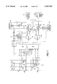
- FIG. 1 is a schematic diagram, primarily in block form, illustrating a circuit interrupter configured in accordance with this invention.
- FIG. 2 is a schematic diagram showing the accessory bus network of this invention.
- FIG. 3A is a representation of a control message employed by this invention.
- FIG. 3B is a representation of a data message employed by this invention.
- FIG. 4 is a graphical representation of examples of modulation that can be employed to establish each bit message represented in FIGS. 3A and B;
- FIG. 5 is a graphical illustration of the load current-versus-time-to-trip curve over a range of load currents from a no trip value to an instantaneous trip value
- FIG. 6 is a perspective view of a display and switch input panel which can be used by this invention.
- FIG. 1 illustrates an electronic trip unit 10 of the invention in combination with ancillary components used for protection and capture of waveforms in an AC electrical power distribution system 12, which represents the load.
- the power distribution system 12 illustrated has three phase conductors 14A, B and C, and a neutral conductor 14N.
- Current transformers 16A, B, C, and N sense current flowing into each of these conductors.
- Current transformer 16G is a zero sequence transformer which indirectly measures ground current by directly measuring the sum of the phase and neutral currents. These currents are sensed by the conditioning circuits 80 and 82 which prepare the signals for processing by the analog-to-digital (A/D) converters 22 and 84, respectively.
- A/D analog-to-digital
- Phase-to-neutral voltages are also sensed from the three phase conductors 14A, B and C by the potential transformers 18A, B and C and are inputted to conditioning circuit 82 for processing by the A/D converter 84.
- the conditioning circuits 80 and 82 scale the current and voltage signals to a suitable range for conversion by the A/D converters 22 and 84 for input to microprocessors 24 and 46, respectively.
- the microprocessors can be microcomputers.
- the A/D converter 84 samples analog voltages and currents at sampling instances determined by interrupts generated by the microprocessor 46 in a manner more particularly described in U.S. Pat. No. 5,600,527, issued Feb. 4, 1997, and the patents referenced therein.
- the microprocessor 46 utilizes the data generated by the digital samples to provide voltage based protection functions for example, under/over voltage protection for the electrical system 12, and also uses the samples for waveform capture and harmonic analysis for metering and display purposes.
- the microprocessor 46 communicates with a display and switch input panel 28 more fully illustrated in FIG. 6.
- the panel 28 serves as one means of interface with the user. It is through the panel 28 that the user can control the operation of the circuit breaker 10, and monitor the AC electrical power system 12, including the harmonic content of the waveform and various measured values such as power factor. To this end, the panel 28 has a display 30 on which the harmonic content of the waveforms can be presented to the user.
- the panel 28 can also be used to input values, e.g., the circuit breaker protection set points.
- the second microprocessor 24 operates in a protection mode to generate a trip signal when any one of the current/time characteristics of a delayed trip protection function is exceeded.
- This trip signal is passed to a trip mechanism 32 which opens separable contacts 34A, B and C in the three phase conductors 14A, B and C of the electrical system 12.
- the trip unit 32 is typically a mechanically latched electronically released mechanism. Although typically not provided in the United States, additional separate contacts can be included to also interrupt current in the neutral conductor 14N.
- the microprocessors 24 and 46 can also communicate with one another through a serial peripheral interface (SPI) link 42. This allows, for example, communication between microprocessor 24 and panel 28.
- the microprocessor 46 can also communicate with a remote processor using the communication link 36 which is an analog transmit and receive circuit known as a transceiver.
- the transceiver 36 enables the circuit breaker 10 to provide information to and be controlled by a remote processor such as a central control network station 38.
- a central control network that can be employed for this purpose is described in U.S. Pat. No. 5,420,799, issued May 30, 1995. Central control networks of that type typically communicate over a common bus using a digital, asynchronous communication protocol.
- FIG. 5 illustrates a plot of the load current value versus time-to-trip from a no trip region to a device that experiences a short period of extremely high load current before entering an instantaneous trip condition.
- Reference character 76 illustrates the normal operating range.
- Reference character 78 identifies the broad current range that can be experienced under different trip conditions spanning from long delay to instantaneous. In some cases the current at the point of trip can be a factor of 10 of the normal operating current value.
- the broad current range makes it very difficult for a single microprocessor such as the microcomputers 24 and 46 shown in FIG. 1 to perform all circuit trip and metering functions accurately.
- FIG. 1 illustrates a further improvement provided by this invention in splitting the processing functions between two processors 24 and 46. In this way the monitoring, voltage based protection and metering functions and algorithms that need to be processed over the normal operating range of the power circuit 12 can be managed by the processor 46 while the overcurrent trip related functions can be handled by the microprocessor 24. Both processors can then communicate with trip circuit 32.
- the conditioning circuit 82 need not scale the monitored currents to the coarse range that otherwise would have been required and the microprocessor 46 has more information available to it from the signal to perform its given functions.
- the conditioning circuits 80 and 82 permit different ranging factors for their respective microprocessors 24 and 46, and enable the respective microprocessors to implement different sampling rates which is sometime beneficial as noted in U.S. Pat. No. 5,600,527.
- the microprocessor 24 provides the overcurrent protection and communicates with the trip circuit 32 to implement an overcurrent instantaneous trip requirement.
- the microprocessor 46 monitors auxiliary contacts 34 on the circuit breaker 11 through a breaker status circuit 26 to indicate the breaker's open/closed condition.
- the microprocessor 46 also communicates with relay outputs 20 that provide local breaker status information such as high load, ground fault, etc. to a remote location.
- the microprocessor 24 communicates through a second transceiver 40 to an accessory bus network 48 which will be described hereafter.
- Present day circuit breakers typically have internal contacts or relays which can be wired to a remote location to provide a remote indication of the digital status of the circuit breaker.
- the status can include an indication of whether the breaker is in an opened, closed, or tripped condition.
- a pair of wires from the breaker is required for each remote status indication.
- Remote open or close control of a circuit breaker can also be provided utilizing a pair of wires for each function from a remote location to the circuit breaker.
- An open command can consist of a voltage on a pair of wires connected to the breakers shunt trip circuit.
- a close command can consist of a voltage on a pair of wires connected to the breakers motor operator.
- a pair of wires is required for each remote digital input/output function. The installation of these wires is both costly and time consuming.
- This invention replaces parallel pairs of separate wires to the various remote accessory devices associated with a given electronic trip unit 10 with a two wire, asynchronous, serial communication network 48 that is illustrated in FIG. 2.
- the network 48 called an accessory bus, is dedicated to a given protective device such as the electronic trip unit 10.
- the electronic trip unit 10 will serve as the bus "master” that controls remote “slave” devices which are the various analog and digital input and output accessory units 50, 52, 54, 56, 58 and 60.
- the information to and from remote accessory units to the master trip unit 10 is carried over a single, rather than multiple, pair of wires 44.
- FIG. 2 shows six representative types of accessory devices, each representative of the type of communication it provides or requires.
- device 50 is representative of an accessory which provides a digital output
- device 52 is representative of an accessory that accepts a digital input
- device 54 is representative of an accessory that provides an analog output
- device 56 is representative of an accessory that accepts an analog input
- remote device 58 is representative of an accessory providing a remote display
- interface 60 is an accessory bus interface for devices such as a personal computer or a communications MODEM.
- a single remote device such as a programmable logic controller.
- One special digital input and output device is a programmable time-delayed close relay which can be used to start a generator following a power outage. The delay would be sent from the electronic trip unit 10 to the relay over the network 48 during normal operation.
- the network 48 can also be provided with an interface 60 that can alternately serve as the interface with a personal computer for purposes of inputting, monitoring and storing breaker trip unit 10 setpoints.
- the interface can also be used to communicate with other networks via a MODEM. Such a MODEM could be a phone connection which initiates a call should a problem exist.
- each slave device can be set by its function, for example, as in Table 1 where "DO” represents digital output devices; “DI” represents digital input devices; where “AO” represents analog output devices; where “AI” represents analog input devices; where “DD” represents digital display devices; and "I” represents an interface to another system.
- each slave device by its function eliminates the need for the electronic trip unit to be programmed for a given application.
- the display and switch input 28 can be used to provide such programming. This allows a single slave device such as a digital output unit 50 to be programmed for multiple purposes. Each slave device would need to have means such as switches to allow its address to be set.
- the display and switch input 28 can be used as shown in FIG. 6 to program the bus.
- the display is shown as having three rows with eight alpha/numeric characters per row. The first row is used for column labels such as slave address (ADD), slave relay number (R) and relay function (FN).
- a digital output slave 50 is identified in row 2 (address 001 H ).
- Its relay 1 (it could have for example 4 relays) is programmed to function as an auxiliary contact (AX).
- Row 3 illustrates that the same slave device 50 has its relay 3 programmed to function as a bell alarm (BA).
- BA bell alarm
- the display and switch input device 28 shown in FIG. 6 can be used to set the desired address, I/O number, and I/O function.
- the trip unit 10 will verify that the slave device at a given address is the type specified. If not, the display would blink to annunciate a programming error.
- the microprocessor 24 within the electronic trip unit 10 communicates with accessory bus devices using control messages illustrated in FIG. 3A and data messages illustrated in FIG. 3B.
- the communication consists of 33 bit asynchronous messages.
- the first two bits, bit 0 and bit 1 are start bits which are used to synchronize the receiver.
- the third bit, bit 2, is a control or data bit. As shown in FIG. 3A, this bit is 1 if the message is a control message. If it is, then bit 10 through bit 22 contains the 12-bit slave destination address.
- Bit 3 through bit 6 consist of an instruction field which is used to set the communications hardware. In this accessory bus application, this field will be 0011 B (binary), or 3 H , which enables the addressed slave device to communicate back to the master microprocessor 24. All other slave devices which are not addressed have their communication interface disabled by the message. This establishes a master-slave communications network as a slave can speak only when enabled.
- the command and subcommand fields, bit 7 through bit 9 and bit 23 through bit 26 are used to pass a command request to the slave.
- the command field could consist of the desired state of the relays while the sub-command could be the complement of the desired state.
- a command of 0010 B would means that relays 4, 3 and 1 should be de-energized while relay 2 is energized.
- the slave will not respond to this request unless the sub-command field contains the complement of the command field or 1101 B .
- the command and subcommand field's definitions are thus specific to the slave device function.
- the data message shown in FIG. 3B is typically used to send data to/from a slave device.
- Bit 3 through bit 26 form a 24-bit data field.
- the communication message protocol master-to-slave could be as follows. First the master microprocessor 24 would send an instruction of 3 H to the slave and a command and subcommand which would instruct the slave to send the value of its two analog inputs and be prepared to accept the desired value of two analog outputs.
- the 24 bit data field would be considered to consist of two 12 bit fields where bit 3 through bit 14 represent analog value 1 and bit 15 through bit 26 represent analog value 2.
- a value less than 333 H such as zero indicates that the analog value is invalid or not used.
- the Analog Input Module 54 shown in FIG. 2 can be used, for example, to measure bus bar temperature with the switchgear near the breaker terminal connection. Such a temperature measurement could be made by means of a resistance temperature detector (RTD). The voltage output of the RTD would be an input to Analog Input Module 54. The Circuit Breaker Electronic Trip Unit 10 can then read this value, display it on the Display and Switch Input 28, and trip the breaker if the temperature reading is too high. A high reading can occur if the breaker's contacts are worn or damaged. A poor contact can have a high resistance which will make the breaker's terminal run too hot, even if the current is below the full load rated value.
- RTD resistance temperature detector
- the Digital Input module 52 shown in FIG. 2 can be used to provide a remote open/close control station. For safety it is desirable to be able to close a breaker without standing directly in front of the unit. Two normally opened switches feeding a Digital Input module 52 can be used for this purpose. One normally opened switch would be labeled OPEN while the other would be labeled CLOSE. The Circuit Breaker Electronic Trip Unit 10 could read these two switches such that if one and only one switch is closed the breaker would perform the requested action. If both are opened or closed no action would be taken. Such a request would be confirmed by multiple reads to avoid false action.
- the Remote Display 58 shown in FIG. 2 could be used to display Circuit Breaker Electronic Trip Unit 10 analog and digital information such as is normally displayed at the trip unit on the Display and Switch Panel 28.
- the Accessory Bus Interface 60 shown in FIG. 2 has a number of uses. When connected to a personal computer (PC) it can be used as a means for programming the trip unit 10.
- the PC would have the ability to establish the desired setpoints by means of its display and then on command download the settings from the PC to the Accessory Bus Interface 60.
- the values would be saved in a non-volatile memory such that the values are preserved during a power outage.
- the Circuit Breaker Electronic Trip Unit 10 would be able to upload these values on command from the PC. Should a trip unit setting be changed using the Display and Switch Panel 28 the new values would be saved within the trip unit 10 and also downloaded to the Accessory Bus Interface 60. In this way the Accessory Bus Interface 60 will always hold the latest setpoint values.
- the Accessory Bus Interface 60 can also be used as a communications MODEM connection such as a phone connection. This would allow the trip unit 10 to initiate a phone call should a circuit problem be detected.
- FIG. 4 illustrates a number of modulation examples that can be used to carry information on the asynchronous, serial communication accessory network.
- Waveform 62 is known as “non return to 0" modulation format “NRZ”;
- waveform 64 is known as “return to 0” modulation format “RTZ”;
- waveform 66 is known as “return to complement” modulation format “RTC”;
- waveform 68 is known as “amplitude shift keying” modulation format “ASK”;
- waveform 70 is known as “frequency shift keying” modulation format “FSK”;
- waveform 72 is known as “phase shift keying” modulation format “PSK.”
- a BIT length is illustrated in FIG. 4 by reference character 74.
- accessory bus 48 and the central controller 38 can employ completely different and distinct protocols.
- the microprocessor 24 performs the overcurrent protection, monitors the breaker status, trips the breaker during overload and fault conditions, and communicates with the microprocessor 46 through a serial peripheral interface (SPI) link 42 and serves as the master for the accessory bus 48.
- the microprocessor 46 provides metering and voltage based protective relay protection, controls output relays, human interfacing by way of display and switch input panel 28, trip implementation under voltage based fault conditions or upon a request from the central controller 37, communication with the microprocessor 24 through the serial peripheral interface (SPI) link 42, and remote communication with the central controller 37 which serves as a master to the circuit interrupter.
- SPI serial peripheral interface
- Either microprocessor 24 or 46 can trip the breaker should the information shared over the synchronous serial port 42 indicate that either or both microprocessors detect a problem.
- this invention provides a number of improvements enabling a layering of networks and improved communication and digital processing capability.
Abstract
Description
TABLE 1 ______________________________________ Type Address Hardware Function______________________________________ DO 001H 1 or more relay outputs auxiliary contacts which follow state of circuitbreaker DO 002H 1 or more relay outputs bell arm contacts which indicate a trip condition DO003H 1 or more relay outputs high load alarm contacts DO004H 1 or more relay outputs ground fault alarm contacts DO005H 1 latched relay time-delayed generator startDI 007H 2 push button inputs remote open/close control input AO 008H 4 to 20 mA output RMS value of highest phase current sealed 4 mA = 0 A and 20 mA = ratedcurrent AI 009H 3 RTD inputs circuit breaker terminal or switchgear bus temperature DD 00AH remote digital display provide remote means for reading breaker setting, metered values, etc. I 00BH RS232/RS485 PC or MODEM interface to electronic trip unit ______________________________________ * H indicates a hexadecimal address
Claims (2)
Priority Applications (5)
| Application Number | Priority Date | Filing Date | Title |
|---|---|---|---|
| US09/055,522 US6167329A (en) | 1998-04-06 | 1998-04-06 | Dual microprocessor electronic trip unit for a circuit interrupter |
| BR9901943-4A BR9901943A (en) | 1998-04-06 | 1999-04-06 | Electronic trip unit and method for monitoring a circuit to perform protection and measurement functions of an electronic trip unit. |
| CA002268233A CA2268233A1 (en) | 1998-04-06 | 1999-04-06 | Dual microprocessor electronic trip unit for a circuit interrupter |
| EP99106792A EP0949734A3 (en) | 1998-04-06 | 1999-04-06 | Dual microprocessor electronic trip unit for a circuit interrupter |
| AU23611/99A AU753319B2 (en) | 1998-04-06 | 1999-04-06 | Dual microprocessor electronic trip unit for a circuit interrupter |
Applications Claiming Priority (1)
| Application Number | Priority Date | Filing Date | Title |
|---|---|---|---|
| US09/055,522 US6167329A (en) | 1998-04-06 | 1998-04-06 | Dual microprocessor electronic trip unit for a circuit interrupter |
Publications (1)
| Publication Number | Publication Date |
|---|---|
| US6167329A true US6167329A (en) | 2000-12-26 |
Family
ID=21998414
Family Applications (1)
| Application Number | Title | Priority Date | Filing Date |
|---|---|---|---|
| US09/055,522 Expired - Lifetime US6167329A (en) | 1998-04-06 | 1998-04-06 | Dual microprocessor electronic trip unit for a circuit interrupter |
Country Status (5)
| Country | Link |
|---|---|
| US (1) | US6167329A (en) |
| EP (1) | EP0949734A3 (en) |
| AU (1) | AU753319B2 (en) |
| BR (1) | BR9901943A (en) |
| CA (1) | CA2268233A1 (en) |
Cited By (81)
| Publication number | Priority date | Publication date | Assignee | Title |
|---|---|---|---|---|
| US20020046007A1 (en) * | 2000-07-27 | 2002-04-18 | Wendorff Wilhard Von | Apparatus for monitoring the proper operation of components of an electrical system carrying out the same or mutually corresponding actions |
| US6459557B1 (en) * | 2000-05-31 | 2002-10-01 | Rockwell Automation Technologies, Inc. | Configurable single/multi-phase overload relay |
| US6473281B1 (en) * | 2000-08-17 | 2002-10-29 | General Electric Company | Automatic protection device with ground fault annunciation |
| US20030181998A1 (en) * | 2000-03-09 | 2003-09-25 | Joachim Schenk | Device for reliably generating signals |
| WO2003079511A1 (en) * | 2002-02-25 | 2003-09-25 | General Electric Company | Circuit protection system |
| US6710482B2 (en) | 2001-08-25 | 2004-03-23 | Lucas Aerospace Power Equipment Corporation | Generator |
| US6731487B2 (en) | 2002-03-20 | 2004-05-04 | General Electric Company | Method and devices for optimizing power consumption of trip units containing microprocessors |
| US20040098170A1 (en) * | 2002-11-15 | 2004-05-20 | Abb Research Ltd. | Installation of a protecftive function in a protective device for an electrical power distribution network |
| US20040130837A1 (en) * | 2003-01-06 | 2004-07-08 | General Electric Company | Circuit protection system |
| US20040169984A1 (en) * | 2002-11-15 | 2004-09-02 | Abb Research Ltd. | Protective device and method for installation of a protective function in a protective device |
| US6850135B1 (en) | 2003-08-01 | 2005-02-01 | Gaton Corporation | Circuit breaker trip unit employing a reset overtravel compensating rotary trip lever |
| US20050024173A1 (en) * | 2003-08-01 | 2005-02-03 | Puskar Michael P. | Circuit breaker trip unit including a plunger resetting a trip actuator mechanism and a trip bar |
| US20050023120A1 (en) * | 2003-08-01 | 2005-02-03 | Puskar Michael P. | Circuit breaker trip unit employing a rotary plunger |
| US20050047045A1 (en) * | 2003-08-29 | 2005-03-03 | Puskar Michael P. | Circuit breaker and trip unit employing multiple function time selector switch |
| US20050231875A1 (en) * | 2004-04-19 | 2005-10-20 | Abb Service S.R.L | Self-supplied electronic protection device for automatic circuit-breakers |
| US20060025944A1 (en) * | 2004-07-30 | 2006-02-02 | Siemens Energy & Automation, Inc. | Power quality indicator |
| US20060119344A1 (en) * | 2004-10-12 | 2006-06-08 | Eaton Corporation | Wireless system for one or more electrical switching apparatus |
| US20070097718A1 (en) * | 2005-10-27 | 2007-05-03 | Anusheel Nahar | Temperature estimation based on a signal oscillation |
| US20080012669A1 (en) * | 2006-07-14 | 2008-01-17 | Square D Company | Burden resistor temperature compensation algorithm |
| US7337081B1 (en) * | 2005-01-27 | 2008-02-26 | Electro Industries/Gauge Tech | Metering device with control functionality and method thereof |
| US20080147334A1 (en) * | 2005-01-27 | 2008-06-19 | Electro Industries/Gauge Tech. | Metering Device with Control Functionally and Method Thereof |
| US20080172192A1 (en) * | 2005-01-27 | 2008-07-17 | Electro Industries/Gauge Tech. | Intelligent Electronic Device with Board-Range High Accuracy |
| US20080215264A1 (en) * | 2005-01-27 | 2008-09-04 | Electro Industries/Gauge Tech. | High speed digital transient waveform detection system and method for use in an intelligent device |
| US20080235355A1 (en) * | 2004-10-20 | 2008-09-25 | Electro Industries/Gauge Tech. | Intelligent Electronic Device for Receiving and Sending Data at High Speeds Over a Network |
| US20090012728A1 (en) * | 2005-01-27 | 2009-01-08 | Electro Industries/Gauge Tech. | System and Method for Multi-Rate Concurrent Waveform Capture and Storage for Power Quality Metering |
| US20090154046A1 (en) * | 2007-12-18 | 2009-06-18 | Robinson Judy A | Trip unit and electrical switching apparatus including a movable indicator to indicate selection of an arc reduction maintenance system current condition |
| US20090195337A1 (en) * | 2008-01-31 | 2009-08-06 | Carlino Harry J | Manually selectable instantaneous current settings for a trip unit and electrical switching apparatus including the same |
| US20090228224A1 (en) * | 2005-01-27 | 2009-09-10 | Electro Industries/Gauge Tech. | Intelligent electronic device with enhanced power quality monitoring and communications capabilities |
| US20100128404A1 (en) * | 2008-11-24 | 2010-05-27 | Square D Company-Schneider Electric | Improper Voltage Detection for Electronic Circuit Breaker |
| US20100127691A1 (en) * | 2008-11-24 | 2010-05-27 | Square D Company - Schneider Electric | Two Pole Circuit Breaker Voltage Monitoring Integration |
| US7747356B2 (en) | 2002-02-25 | 2010-06-29 | General Electric Company | Integrated protection, monitoring, and control system |
| ITBO20090029A1 (en) * | 2009-01-23 | 2010-07-24 | Giuseppe Giuliano | INTERRUPTION DEVICE FOR ELECTRIC CURRENT DELIVERY WITH AN EMERGENCY SYSTEM |
| US20100324845A1 (en) * | 2005-01-27 | 2010-12-23 | Electro Industries/Gauge Tech. | Intelligent electronic device with enhanced power quality monitoring and communication capabilities |
| US20100328825A1 (en) * | 2009-06-29 | 2010-12-30 | Rockwell Automation Technologies, Inc. | System and method for detecting a fault condition |
| US20110026181A1 (en) * | 2008-03-05 | 2011-02-03 | Dirk Graupner | Protective switching device for monitoring the electrical current flow to an electrical user and method for monitoring the electrical current flow to an electrical user by way of a protective switching device |
| US20120120536A1 (en) * | 2010-11-12 | 2012-05-17 | Rivers Jr Cecil | Shared memory architecture for protection of electrical distribution equipment |
| CN103066549A (en) * | 2011-10-21 | 2013-04-24 | 施耐德电器工业公司 | A relay with an intermediate alert mechanism |
| US20130242445A1 (en) * | 2011-12-20 | 2013-09-19 | Landis+Gyr Inc. | Service Voltage Load Protection in an Electric Utility Meter |
| US20140139014A1 (en) * | 2012-11-20 | 2014-05-22 | Thales | Power over data transmission |
| US8737033B2 (en) | 2012-09-10 | 2014-05-27 | Eaton Corporation | Circuit interrupter employing non-volatile memory for improved diagnostics |
| US20140176117A1 (en) * | 2007-04-03 | 2014-06-26 | Electro Industries/Gauge Tech. | High Speed Digital Transient Waveform Detection System and Method for Use in an Intelligent Electronic Device |
| US8797202B2 (en) | 2008-03-13 | 2014-08-05 | Electro Industries/Gauge Tech | Intelligent electronic device having circuitry for highly accurate voltage sensing |
| US8810987B2 (en) | 2012-10-19 | 2014-08-19 | General Electric Company | Method and apparatus for power management in ETU within a circuit breaker when used as a host controller |
| RU2531038C2 (en) * | 2013-02-04 | 2014-10-20 | Александр Николаевич Беляев | Method for monitoring state of electrical network and power facility and device for its implementation |
| US8930153B2 (en) | 2005-01-27 | 2015-01-06 | Electro Industries/Gauge Tech | Metering device with control functionality and method thereof |
| US9194898B2 (en) | 2005-01-27 | 2015-11-24 | Electro Industries/Gauge Tech | Intelligent electronic device and method thereof |
| US9214797B2 (en) | 2013-02-13 | 2015-12-15 | General Electric Company | Apparatus, systems, and methods for operation of a trip unit in a circuit protection device |
| US20160294179A1 (en) * | 2015-04-06 | 2016-10-06 | Atom Power, LLC | Dynamic coordination of protection devices in electrical distribution systems |
| US9482555B2 (en) | 2008-04-03 | 2016-11-01 | Electro Industries/Gauge Tech. | System and method for improved data transfer from an IED |
| US9989618B2 (en) | 2007-04-03 | 2018-06-05 | Electro Industries/Gaugetech | Intelligent electronic device with constant calibration capabilities for high accuracy measurements |
| US10275840B2 (en) | 2011-10-04 | 2019-04-30 | Electro Industries/Gauge Tech | Systems and methods for collecting, analyzing, billing, and reporting data from intelligent electronic devices |
| US10303860B2 (en) | 2011-10-04 | 2019-05-28 | Electro Industries/Gauge Tech | Security through layers in an intelligent electronic device |
| US10345416B2 (en) | 2007-03-27 | 2019-07-09 | Electro Industries/Gauge Tech | Intelligent electronic device with broad-range high accuracy |
| US10430263B2 (en) | 2016-02-01 | 2019-10-01 | Electro Industries/Gauge Tech | Devices, systems and methods for validating and upgrading firmware in intelligent electronic devices |
| US10641618B2 (en) | 2004-10-20 | 2020-05-05 | Electro Industries/Gauge Tech | On-line web accessed energy meter |
| US10672578B2 (en) | 2015-08-26 | 2020-06-02 | David Stuckey Investments Pty Ltd | Solid-state relay |
| US10771532B2 (en) | 2011-10-04 | 2020-09-08 | Electro Industries/Gauge Tech | Intelligent electronic devices, systems and methods for communicating messages over a network |
| US10778320B2 (en) | 2011-10-21 | 2020-09-15 | Schneider Electric Logistics Asia Pte Ltd. | Method and relay for communicating a value of a parameter of a source to be monitored |
| US10845399B2 (en) | 2007-04-03 | 2020-11-24 | Electro Industries/Gaugetech | System and method for performing data transfers in an intelligent electronic device |
| US10862784B2 (en) | 2011-10-04 | 2020-12-08 | Electro Industries/Gauge Tech | Systems and methods for processing meter information in a network of intelligent electronic devices |
| US10958435B2 (en) | 2015-12-21 | 2021-03-23 | Electro Industries/ Gauge Tech | Providing security in an intelligent electronic device |
| US10985548B2 (en) | 2018-10-01 | 2021-04-20 | Intelesol, Llc | Circuit interrupter with optical connection |
| US11056981B2 (en) | 2018-07-07 | 2021-07-06 | Intelesol, Llc | Method and apparatus for signal extraction with sample and hold and release |
| US11064586B2 (en) | 2018-12-17 | 2021-07-13 | Intelesol, Llc | AC-driven light-emitting diode systems |
| US11170964B2 (en) | 2019-05-18 | 2021-11-09 | Amber Solutions, Inc. | Intelligent circuit breakers with detection circuitry configured to detect fault conditions |
| US11205011B2 (en) | 2018-09-27 | 2021-12-21 | Amber Solutions, Inc. | Privacy and the management of permissions |
| US11334388B2 (en) | 2018-09-27 | 2022-05-17 | Amber Solutions, Inc. | Infrastructure support to enhance resource-constrained device capabilities |
| US11349296B2 (en) | 2018-10-01 | 2022-05-31 | Intelesol, Llc | Solid-state circuit interrupters |
| US11349297B2 (en) | 2020-01-21 | 2022-05-31 | Amber Solutions, Inc. | Intelligent circuit interruption |
| US11495956B1 (en) | 2021-08-24 | 2022-11-08 | Rockwell Automation Technologies, Inc. | Widerange shunt and undervoltage |
| US11581725B2 (en) | 2018-07-07 | 2023-02-14 | Intelesol, Llc | Solid-state power interrupters |
| US11644490B2 (en) | 2007-04-03 | 2023-05-09 | El Electronics Llc | Digital power metering system with serial peripheral interface (SPI) multimaster communications |
| US11670946B2 (en) | 2020-08-11 | 2023-06-06 | Amber Semiconductor, Inc. | Intelligent energy source monitoring and selection control system |
| US11671029B2 (en) | 2018-07-07 | 2023-06-06 | Intelesol, Llc | AC to DC converters |
| US11686594B2 (en) | 2018-02-17 | 2023-06-27 | Ei Electronics Llc | Devices, systems and methods for a cloud-based meter management system |
| US11686749B2 (en) | 2004-10-25 | 2023-06-27 | El Electronics Llc | Power meter having multiple ethernet ports |
| US11734396B2 (en) | 2014-06-17 | 2023-08-22 | El Electronics Llc | Security through layers in an intelligent electronic device |
| US11734704B2 (en) | 2018-02-17 | 2023-08-22 | Ei Electronics Llc | Devices, systems and methods for the collection of meter data in a common, globally accessible, group of servers, to provide simpler configuration, collection, viewing, and analysis of the meter data |
| US11754997B2 (en) | 2018-02-17 | 2023-09-12 | Ei Electronics Llc | Devices, systems and methods for predicting future consumption values of load(s) in power distribution systems |
| US11816465B2 (en) | 2013-03-15 | 2023-11-14 | Ei Electronics Llc | Devices, systems and methods for tracking and upgrading firmware in intelligent electronic devices |
| US11863589B2 (en) | 2019-06-07 | 2024-01-02 | Ei Electronics Llc | Enterprise security in meters |
Families Citing this family (3)
| Publication number | Priority date | Publication date | Assignee | Title |
|---|---|---|---|---|
| SE516685C2 (en) | 1999-09-23 | 2002-02-12 | Applied Polytechnics Inc | Method, system and apparatus for measuring electrical energy, measuring, communicating and operating via a current transformer |
| WO2004061462A1 (en) * | 2002-12-23 | 2004-07-22 | Power Measurement Ltd. | Power monitoring integrated circuit with communication interface |
| SG189580A1 (en) * | 2011-10-21 | 2013-05-31 | Schneider Electric South East Asia Hq Pte Ltd | An automatic configurable relay |
Citations (10)
| Publication number | Priority date | Publication date | Assignee | Title |
|---|---|---|---|---|
| US4428022A (en) * | 1980-04-15 | 1984-01-24 | Westinghouse Electric Corp. | Circuit interrupter with digital trip unit and automatic reset |
| US4672555A (en) * | 1984-10-18 | 1987-06-09 | Massachusetts Institute Of Technology | Digital ac monitor |
| US4996646A (en) * | 1988-03-31 | 1991-02-26 | Square D Company | Microprocessor-controlled circuit breaker and system |
| US5233538A (en) * | 1990-04-02 | 1993-08-03 | Square D Company | Waveform capturing arrangement in a distributed power network |
| US5420799A (en) * | 1991-08-15 | 1995-05-30 | Eaton Corporation | Circuit breaker - associated backpack unit for lower-link communication with a PC computer monitoring system and energy monitoring system using a plurality of such backpack units |
| US5500781A (en) * | 1994-05-09 | 1996-03-19 | General Electric Company | Digital circuit interrupter with multiple accessory function |
| US5524083A (en) * | 1988-03-31 | 1996-06-04 | Square D Company | Decentralized, modular tripping arrangement |
| US5525985A (en) * | 1990-12-28 | 1996-06-11 | Eaton Corporation | Sure chip |
| US5600527A (en) * | 1994-12-22 | 1997-02-04 | Eaton Corporation | Circuit interrupter providing protection and waveform capture for harmonic analysis |
| US6005757A (en) * | 1998-05-11 | 1999-12-21 | Eaton Corporation | Electrical switching device or trip unit acquiring predetermined settings from another electrical switching device or trip unit |
Family Cites Families (1)
| Publication number | Priority date | Publication date | Assignee | Title |
|---|---|---|---|---|
| US5369356A (en) * | 1991-08-30 | 1994-11-29 | Siemens Energy & Automation, Inc. | Distributed current and voltage sampling function for an electric power monitoring unit |
-
1998
- 1998-04-06 US US09/055,522 patent/US6167329A/en not_active Expired - Lifetime
-
1999
- 1999-04-06 CA CA002268233A patent/CA2268233A1/en not_active Abandoned
- 1999-04-06 EP EP99106792A patent/EP0949734A3/en not_active Withdrawn
- 1999-04-06 BR BR9901943-4A patent/BR9901943A/en not_active IP Right Cessation
- 1999-04-06 AU AU23611/99A patent/AU753319B2/en not_active Ceased
Patent Citations (10)
| Publication number | Priority date | Publication date | Assignee | Title |
|---|---|---|---|---|
| US4428022A (en) * | 1980-04-15 | 1984-01-24 | Westinghouse Electric Corp. | Circuit interrupter with digital trip unit and automatic reset |
| US4672555A (en) * | 1984-10-18 | 1987-06-09 | Massachusetts Institute Of Technology | Digital ac monitor |
| US4996646A (en) * | 1988-03-31 | 1991-02-26 | Square D Company | Microprocessor-controlled circuit breaker and system |
| US5524083A (en) * | 1988-03-31 | 1996-06-04 | Square D Company | Decentralized, modular tripping arrangement |
| US5233538A (en) * | 1990-04-02 | 1993-08-03 | Square D Company | Waveform capturing arrangement in a distributed power network |
| US5525985A (en) * | 1990-12-28 | 1996-06-11 | Eaton Corporation | Sure chip |
| US5420799A (en) * | 1991-08-15 | 1995-05-30 | Eaton Corporation | Circuit breaker - associated backpack unit for lower-link communication with a PC computer monitoring system and energy monitoring system using a plurality of such backpack units |
| US5500781A (en) * | 1994-05-09 | 1996-03-19 | General Electric Company | Digital circuit interrupter with multiple accessory function |
| US5600527A (en) * | 1994-12-22 | 1997-02-04 | Eaton Corporation | Circuit interrupter providing protection and waveform capture for harmonic analysis |
| US6005757A (en) * | 1998-05-11 | 1999-12-21 | Eaton Corporation | Electrical switching device or trip unit acquiring predetermined settings from another electrical switching device or trip unit |
Cited By (135)
| Publication number | Priority date | Publication date | Assignee | Title |
|---|---|---|---|---|
| US20030181998A1 (en) * | 2000-03-09 | 2003-09-25 | Joachim Schenk | Device for reliably generating signals |
| US6459557B1 (en) * | 2000-05-31 | 2002-10-01 | Rockwell Automation Technologies, Inc. | Configurable single/multi-phase overload relay |
| US6807514B2 (en) * | 2000-07-27 | 2004-10-19 | Infineon Technologies Ag | Apparatus for monitoring the proper operation of components of an electrical system carrying out the same or mutually corresponding actions |
| US20020046007A1 (en) * | 2000-07-27 | 2002-04-18 | Wendorff Wilhard Von | Apparatus for monitoring the proper operation of components of an electrical system carrying out the same or mutually corresponding actions |
| US6473281B1 (en) * | 2000-08-17 | 2002-10-29 | General Electric Company | Automatic protection device with ground fault annunciation |
| US6710482B2 (en) | 2001-08-25 | 2004-03-23 | Lucas Aerospace Power Equipment Corporation | Generator |
| US7747356B2 (en) | 2002-02-25 | 2010-06-29 | General Electric Company | Integrated protection, monitoring, and control system |
| WO2003079511A1 (en) * | 2002-02-25 | 2003-09-25 | General Electric Company | Circuit protection system |
| US8213144B2 (en) | 2002-02-25 | 2012-07-03 | General Electric Company | Circuit protection system |
| US6731487B2 (en) | 2002-03-20 | 2004-05-04 | General Electric Company | Method and devices for optimizing power consumption of trip units containing microprocessors |
| US20040098170A1 (en) * | 2002-11-15 | 2004-05-20 | Abb Research Ltd. | Installation of a protecftive function in a protective device for an electrical power distribution network |
| US20040169984A1 (en) * | 2002-11-15 | 2004-09-02 | Abb Research Ltd. | Protective device and method for installation of a protective function in a protective device |
| US7319922B2 (en) * | 2002-11-15 | 2008-01-15 | Abb Research Ltd | Protective device and method for installation of a protective function in a protective device |
| US7103453B2 (en) * | 2002-11-15 | 2006-09-05 | Abb Research Ltd | Installation of a protective function in a protective device for an electrical power distribution network |
| US20040130837A1 (en) * | 2003-01-06 | 2004-07-08 | General Electric Company | Circuit protection system |
| US7986503B2 (en) * | 2003-01-06 | 2011-07-26 | General Electric Company | Circuit protection system |
| US20050024172A1 (en) * | 2003-08-01 | 2005-02-03 | Puskar Michael P. | Circuit breaker trip unit employing a reset overtravel compensating rotary trip lever |
| US6921873B2 (en) | 2003-08-01 | 2005-07-26 | Eaton Corporation | Circuit breaker trip unit employing a rotary plunger |
| US6853279B1 (en) | 2003-08-01 | 2005-02-08 | Eaton Corporation | Circuit breaker trip unit including a plunger resetting a trip actuator mechanism and a trip bar |
| US20050023120A1 (en) * | 2003-08-01 | 2005-02-03 | Puskar Michael P. | Circuit breaker trip unit employing a rotary plunger |
| US20050024173A1 (en) * | 2003-08-01 | 2005-02-03 | Puskar Michael P. | Circuit breaker trip unit including a plunger resetting a trip actuator mechanism and a trip bar |
| US6850135B1 (en) | 2003-08-01 | 2005-02-01 | Gaton Corporation | Circuit breaker trip unit employing a reset overtravel compensating rotary trip lever |
| US20050047045A1 (en) * | 2003-08-29 | 2005-03-03 | Puskar Michael P. | Circuit breaker and trip unit employing multiple function time selector switch |
| US20050231875A1 (en) * | 2004-04-19 | 2005-10-20 | Abb Service S.R.L | Self-supplied electronic protection device for automatic circuit-breakers |
| US7417840B2 (en) * | 2004-04-19 | 2008-08-26 | Abb S.P.A. | Self-supplied electronic protection device for automatic circuit-breakers |
| CN100546141C (en) * | 2004-04-19 | 2009-09-30 | Abb股份公司 | The self-supplied electronic protective device that is used for automatic circuit breaker |
| US20060025944A1 (en) * | 2004-07-30 | 2006-02-02 | Siemens Energy & Automation, Inc. | Power quality indicator |
| US7085662B2 (en) | 2004-07-30 | 2006-08-01 | Siemens Energy & Automation, Inc. | Power quality indicator |
| US7417554B2 (en) * | 2004-10-12 | 2008-08-26 | Gaton Corporation | Wireless system for one or more electrical switching apparatus |
| US20060119344A1 (en) * | 2004-10-12 | 2006-06-08 | Eaton Corporation | Wireless system for one or more electrical switching apparatus |
| US10641618B2 (en) | 2004-10-20 | 2020-05-05 | Electro Industries/Gauge Tech | On-line web accessed energy meter |
| US11754418B2 (en) | 2004-10-20 | 2023-09-12 | Ei Electronics Llc | On-line web accessed energy meter |
| US20080235355A1 (en) * | 2004-10-20 | 2008-09-25 | Electro Industries/Gauge Tech. | Intelligent Electronic Device for Receiving and Sending Data at High Speeds Over a Network |
| US10628053B2 (en) | 2004-10-20 | 2020-04-21 | Electro Industries/Gauge Tech | Intelligent electronic device for receiving and sending data at high speeds over a network |
| US9080894B2 (en) | 2004-10-20 | 2015-07-14 | Electro Industries/Gauge Tech | Intelligent electronic device for receiving and sending data at high speeds over a network |
| US11686749B2 (en) | 2004-10-25 | 2023-06-27 | El Electronics Llc | Power meter having multiple ethernet ports |
| US8930153B2 (en) | 2005-01-27 | 2015-01-06 | Electro Industries/Gauge Tech | Metering device with control functionality and method thereof |
| US8190381B2 (en) | 2005-01-27 | 2012-05-29 | Electro Industries/Gauge Tech | Intelligent electronic device with enhanced power quality monitoring and communications capabilities |
| US20080147334A1 (en) * | 2005-01-27 | 2008-06-19 | Electro Industries/Gauge Tech. | Metering Device with Control Functionally and Method Thereof |
| US7337081B1 (en) * | 2005-01-27 | 2008-02-26 | Electro Industries/Gauge Tech | Metering device with control functionality and method thereof |
| US9194898B2 (en) | 2005-01-27 | 2015-11-24 | Electro Industries/Gauge Tech | Intelligent electronic device and method thereof |
| US10823770B2 (en) | 2005-01-27 | 2020-11-03 | Electro Industries/Gaugetech | Intelligent electronic device and method thereof |
| US9903895B2 (en) | 2005-01-27 | 2018-02-27 | Electro Industries/Gauge Tech | Intelligent electronic device and method thereof |
| US20100324845A1 (en) * | 2005-01-27 | 2010-12-23 | Electro Industries/Gauge Tech. | Intelligent electronic device with enhanced power quality monitoring and communication capabilities |
| US20080215264A1 (en) * | 2005-01-27 | 2008-09-04 | Electro Industries/Gauge Tech. | High speed digital transient waveform detection system and method for use in an intelligent device |
| US20080172192A1 (en) * | 2005-01-27 | 2008-07-17 | Electro Industries/Gauge Tech. | Intelligent Electronic Device with Board-Range High Accuracy |
| US8878517B2 (en) | 2005-01-27 | 2014-11-04 | Electro Industries/Gauge Tech | Intelligent electronic device with broad-range high accuracy |
| US7899630B2 (en) | 2005-01-27 | 2011-03-01 | Electro Industries/Gauge Tech | Metering device with control functionality and method thereof |
| US11366143B2 (en) | 2005-01-27 | 2022-06-21 | Electro Industries/Gaugetech | Intelligent electronic device with enhanced power quality monitoring and communication capabilities |
| US8666688B2 (en) | 2005-01-27 | 2014-03-04 | Electro Industries/Gauge Tech | High speed digital transient waveform detection system and method for use in an intelligent electronic device |
| US7996171B2 (en) | 2005-01-27 | 2011-08-09 | Electro Industries/Gauge Tech | Intelligent electronic device with broad-range high accuracy |
| US8862435B2 (en) * | 2005-01-27 | 2014-10-14 | Electric Industries/Gauge Tech | Intelligent electronic device with enhanced power quality monitoring and communication capabilities |
| US8121801B2 (en) | 2005-01-27 | 2012-02-21 | Electro Industries/Gauge Tech | System and method for multi-rate concurrent waveform capture and storage for power quality metering |
| US8160824B2 (en) * | 2005-01-27 | 2012-04-17 | Electro Industries/Gauge Tech | Intelligent electronic device with enhanced power quality monitoring and communication capabilities |
| US11366145B2 (en) | 2005-01-27 | 2022-06-21 | Electro Industries/Gauge Tech | Intelligent electronic device with enhanced power quality monitoring and communications capability |
| US20090228224A1 (en) * | 2005-01-27 | 2009-09-10 | Electro Industries/Gauge Tech. | Intelligent electronic device with enhanced power quality monitoring and communications capabilities |
| US20090012728A1 (en) * | 2005-01-27 | 2009-01-08 | Electro Industries/Gauge Tech. | System and Method for Multi-Rate Concurrent Waveform Capture and Storage for Power Quality Metering |
| US8700347B2 (en) | 2005-01-27 | 2014-04-15 | Electro Industries/Gauge Tech | Intelligent electronic device with enhanced power quality monitoring and communications capability |
| US20120209552A1 (en) * | 2005-01-27 | 2012-08-16 | Electro Industries/Gauge Tech | Intelligent electronic device with enhanced power quality monitoring and communication capabilities |
| US20070097718A1 (en) * | 2005-10-27 | 2007-05-03 | Anusheel Nahar | Temperature estimation based on a signal oscillation |
| US7522434B2 (en) * | 2005-10-27 | 2009-04-21 | Wisconsin Alumni Research Foundation | Temperature estimation based on a signal oscillation |
| US7859802B2 (en) * | 2006-07-14 | 2010-12-28 | William Davison | Burden resistor temperature compensation algorithm |
| US20080012669A1 (en) * | 2006-07-14 | 2008-01-17 | Square D Company | Burden resistor temperature compensation algorithm |
| US10345416B2 (en) | 2007-03-27 | 2019-07-09 | Electro Industries/Gauge Tech | Intelligent electronic device with broad-range high accuracy |
| US11307227B2 (en) * | 2007-04-03 | 2022-04-19 | Electro Industries/Gauge Tech | High speed digital transient waveform detection system and method for use in an intelligent electronic device |
| US11644490B2 (en) | 2007-04-03 | 2023-05-09 | El Electronics Llc | Digital power metering system with serial peripheral interface (SPI) multimaster communications |
| US11635455B2 (en) | 2007-04-03 | 2023-04-25 | El Electronics Llc | System and method for performing data transfers in an intelligent electronic device |
| US20140176117A1 (en) * | 2007-04-03 | 2014-06-26 | Electro Industries/Gauge Tech. | High Speed Digital Transient Waveform Detection System and Method for Use in an Intelligent Electronic Device |
| US9989618B2 (en) | 2007-04-03 | 2018-06-05 | Electro Industries/Gaugetech | Intelligent electronic device with constant calibration capabilities for high accuracy measurements |
| US10845399B2 (en) | 2007-04-03 | 2020-11-24 | Electro Industries/Gaugetech | System and method for performing data transfers in an intelligent electronic device |
| US20090154046A1 (en) * | 2007-12-18 | 2009-06-18 | Robinson Judy A | Trip unit and electrical switching apparatus including a movable indicator to indicate selection of an arc reduction maintenance system current condition |
| US20090195337A1 (en) * | 2008-01-31 | 2009-08-06 | Carlino Harry J | Manually selectable instantaneous current settings for a trip unit and electrical switching apparatus including the same |
| US8385037B2 (en) | 2008-03-05 | 2013-02-26 | Siemens Aktiengesellschaft | Protective switching device for monitoring the electrical current flow to an electrical user and method for monitoring the electrical current flow to an electrical user by way of a protective switching device |
| US20110026181A1 (en) * | 2008-03-05 | 2011-02-03 | Dirk Graupner | Protective switching device for monitoring the electrical current flow to an electrical user and method for monitoring the electrical current flow to an electrical user by way of a protective switching device |
| US8797202B2 (en) | 2008-03-13 | 2014-08-05 | Electro Industries/Gauge Tech | Intelligent electronic device having circuitry for highly accurate voltage sensing |
| US9482555B2 (en) | 2008-04-03 | 2016-11-01 | Electro Industries/Gauge Tech. | System and method for improved data transfer from an IED |
| US8106670B2 (en) | 2008-11-24 | 2012-01-31 | Schneider Electric USA, Inc. | Two pole circuit breaker voltage monitoring integration |
| US20100127691A1 (en) * | 2008-11-24 | 2010-05-27 | Square D Company - Schneider Electric | Two Pole Circuit Breaker Voltage Monitoring Integration |
| US20100128404A1 (en) * | 2008-11-24 | 2010-05-27 | Square D Company-Schneider Electric | Improper Voltage Detection for Electronic Circuit Breaker |
| US8649143B2 (en) | 2008-11-24 | 2014-02-11 | Schneider Electric USA, Inc. | Improper voltage detection for electronic circuit breaker |
| ITBO20090029A1 (en) * | 2009-01-23 | 2010-07-24 | Giuseppe Giuliano | INTERRUPTION DEVICE FOR ELECTRIC CURRENT DELIVERY WITH AN EMERGENCY SYSTEM |
| US20100328825A1 (en) * | 2009-06-29 | 2010-12-30 | Rockwell Automation Technologies, Inc. | System and method for detecting a fault condition |
| US7965478B2 (en) * | 2009-06-29 | 2011-06-21 | Rockwell Automation Technologies, Inc. | System and method for detecting a fault condition |
| CN102610261B (en) * | 2010-11-12 | 2016-08-03 | 通用电气公司 | Shared memory architecture for controller switching equipment protection |
| US20120120536A1 (en) * | 2010-11-12 | 2012-05-17 | Rivers Jr Cecil | Shared memory architecture for protection of electrical distribution equipment |
| US8526151B2 (en) * | 2010-11-12 | 2013-09-03 | General Electric Company | Shared memory architecture for protection of electrical distribution equipment |
| CN102610261A (en) * | 2010-11-12 | 2012-07-25 | 通用电气公司 | Shared memory architecture for protection of electrical distribution equipment |
| US10771532B2 (en) | 2011-10-04 | 2020-09-08 | Electro Industries/Gauge Tech | Intelligent electronic devices, systems and methods for communicating messages over a network |
| US10275840B2 (en) | 2011-10-04 | 2019-04-30 | Electro Industries/Gauge Tech | Systems and methods for collecting, analyzing, billing, and reporting data from intelligent electronic devices |
| US10303860B2 (en) | 2011-10-04 | 2019-05-28 | Electro Industries/Gauge Tech | Security through layers in an intelligent electronic device |
| US10862784B2 (en) | 2011-10-04 | 2020-12-08 | Electro Industries/Gauge Tech | Systems and methods for processing meter information in a network of intelligent electronic devices |
| US10922950B2 (en) | 2011-10-21 | 2021-02-16 | Schneider Electric Logistics Asia Pte Ltd. | Relay with an intermediate alert mechanism |
| US10778320B2 (en) | 2011-10-21 | 2020-09-15 | Schneider Electric Logistics Asia Pte Ltd. | Method and relay for communicating a value of a parameter of a source to be monitored |
| CN103066549B (en) * | 2011-10-21 | 2016-09-07 | 施耐德电器工业公司 | Relay with middle alert mechanism |
| CN103066549A (en) * | 2011-10-21 | 2013-04-24 | 施耐德电器工业公司 | A relay with an intermediate alert mechanism |
| US9252588B2 (en) * | 2011-12-20 | 2016-02-02 | Landis+Gyr, Inc. | Service voltage load protection in an electric utility meter |
| US20130242445A1 (en) * | 2011-12-20 | 2013-09-19 | Landis+Gyr Inc. | Service Voltage Load Protection in an Electric Utility Meter |
| US8737033B2 (en) | 2012-09-10 | 2014-05-27 | Eaton Corporation | Circuit interrupter employing non-volatile memory for improved diagnostics |
| US8810987B2 (en) | 2012-10-19 | 2014-08-19 | General Electric Company | Method and apparatus for power management in ETU within a circuit breaker when used as a host controller |
| US9819510B2 (en) * | 2012-11-20 | 2017-11-14 | Thales | Power over data transmission |
| US20140139014A1 (en) * | 2012-11-20 | 2014-05-22 | Thales | Power over data transmission |
| RU2531038C2 (en) * | 2013-02-04 | 2014-10-20 | Александр Николаевич Беляев | Method for monitoring state of electrical network and power facility and device for its implementation |
| US9214797B2 (en) | 2013-02-13 | 2015-12-15 | General Electric Company | Apparatus, systems, and methods for operation of a trip unit in a circuit protection device |
| US11816465B2 (en) | 2013-03-15 | 2023-11-14 | Ei Electronics Llc | Devices, systems and methods for tracking and upgrading firmware in intelligent electronic devices |
| US11734396B2 (en) | 2014-06-17 | 2023-08-22 | El Electronics Llc | Security through layers in an intelligent electronic device |
| US20160294179A1 (en) * | 2015-04-06 | 2016-10-06 | Atom Power, LLC | Dynamic coordination of protection devices in electrical distribution systems |
| US10276321B2 (en) * | 2015-04-06 | 2019-04-30 | Atom Power, Inc. | Dynamic coordination of protection devices in electrical distribution systems |
| US10672578B2 (en) | 2015-08-26 | 2020-06-02 | David Stuckey Investments Pty Ltd | Solid-state relay |
| US11870910B2 (en) | 2015-12-21 | 2024-01-09 | Ei Electronics Llc | Providing security in an intelligent electronic device |
| US10958435B2 (en) | 2015-12-21 | 2021-03-23 | Electro Industries/ Gauge Tech | Providing security in an intelligent electronic device |
| US10430263B2 (en) | 2016-02-01 | 2019-10-01 | Electro Industries/Gauge Tech | Devices, systems and methods for validating and upgrading firmware in intelligent electronic devices |
| US11734704B2 (en) | 2018-02-17 | 2023-08-22 | Ei Electronics Llc | Devices, systems and methods for the collection of meter data in a common, globally accessible, group of servers, to provide simpler configuration, collection, viewing, and analysis of the meter data |
| US11754997B2 (en) | 2018-02-17 | 2023-09-12 | Ei Electronics Llc | Devices, systems and methods for predicting future consumption values of load(s) in power distribution systems |
| US11686594B2 (en) | 2018-02-17 | 2023-06-27 | Ei Electronics Llc | Devices, systems and methods for a cloud-based meter management system |
| US11671029B2 (en) | 2018-07-07 | 2023-06-06 | Intelesol, Llc | AC to DC converters |
| US11056981B2 (en) | 2018-07-07 | 2021-07-06 | Intelesol, Llc | Method and apparatus for signal extraction with sample and hold and release |
| US11581725B2 (en) | 2018-07-07 | 2023-02-14 | Intelesol, Llc | Solid-state power interrupters |
| US11764565B2 (en) | 2018-07-07 | 2023-09-19 | Intelesol, Llc | Solid-state power interrupters |
| US11334388B2 (en) | 2018-09-27 | 2022-05-17 | Amber Solutions, Inc. | Infrastructure support to enhance resource-constrained device capabilities |
| US11205011B2 (en) | 2018-09-27 | 2021-12-21 | Amber Solutions, Inc. | Privacy and the management of permissions |
| US10985548B2 (en) | 2018-10-01 | 2021-04-20 | Intelesol, Llc | Circuit interrupter with optical connection |
| US11791616B2 (en) | 2018-10-01 | 2023-10-17 | Intelesol, Llc | Solid-state circuit interrupters |
| US11349296B2 (en) | 2018-10-01 | 2022-05-31 | Intelesol, Llc | Solid-state circuit interrupters |
| US11363690B2 (en) | 2018-12-17 | 2022-06-14 | Intelesol, Llc | AC-driven light-emitting diode systems |
| US11064586B2 (en) | 2018-12-17 | 2021-07-13 | Intelesol, Llc | AC-driven light-emitting diode systems |
| US11348752B2 (en) | 2019-05-18 | 2022-05-31 | Amber Solutions, Inc. | Intelligent circuit breakers with air-gap and solid-state switches |
| US11342151B2 (en) | 2019-05-18 | 2022-05-24 | Amber Solutions, Inc. | Intelligent circuit breakers with visual indicators to provide operational status |
| US11682891B2 (en) | 2019-05-18 | 2023-06-20 | Amber Semiconductor, Inc. | Intelligent circuit breakers with internal short circuit control system |
| US11170964B2 (en) | 2019-05-18 | 2021-11-09 | Amber Solutions, Inc. | Intelligent circuit breakers with detection circuitry configured to detect fault conditions |
| US11373831B2 (en) | 2019-05-18 | 2022-06-28 | Amber Solutions, Inc. | Intelligent circuit breakers |
| US11551899B2 (en) | 2019-05-18 | 2023-01-10 | Amber Semiconductor, Inc. | Intelligent circuit breakers with solid-state bidirectional switches |
| US11863589B2 (en) | 2019-06-07 | 2024-01-02 | Ei Electronics Llc | Enterprise security in meters |
| US11349297B2 (en) | 2020-01-21 | 2022-05-31 | Amber Solutions, Inc. | Intelligent circuit interruption |
| US11670946B2 (en) | 2020-08-11 | 2023-06-06 | Amber Semiconductor, Inc. | Intelligent energy source monitoring and selection control system |
| US11495956B1 (en) | 2021-08-24 | 2022-11-08 | Rockwell Automation Technologies, Inc. | Widerange shunt and undervoltage |
Also Published As
| Publication number | Publication date |
|---|---|
| AU753319B2 (en) | 2002-10-17 |
| CA2268233A1 (en) | 1999-10-06 |
| EP0949734A2 (en) | 1999-10-13 |
| EP0949734A3 (en) | 2001-04-04 |
| AU2361199A (en) | 1999-10-14 |
| BR9901943A (en) | 2000-01-11 |
Similar Documents
| Publication | Publication Date | Title |
|---|---|---|
| US6167329A (en) | Dual microprocessor electronic trip unit for a circuit interrupter | |
| US6175780B1 (en) | Accessory network for an electronic trip unit | |
| US6005757A (en) | Electrical switching device or trip unit acquiring predetermined settings from another electrical switching device or trip unit | |
| US5311392A (en) | Dual processor electric power trip unit | |
| EP2028677B1 (en) | Method and electrical switching apparatus including a number of accessories employing wireless communication | |
| US5309312A (en) | Overcurrent protection relay with communications | |
| CA2271441C (en) | Electrical switching apparatus employing a circuit for selectively enabling and disabling a close actuator mechanism | |
| US5369356A (en) | Distributed current and voltage sampling function for an electric power monitoring unit | |
| US5335135A (en) | Fault recording system for an electric power trip unit | |
| CA2162350A1 (en) | Circuit breaker using bimetal of thermal-magnetic trip to sense current | |
| AU749406B2 (en) | Electrical switching apparatus employing interlocks for first and second trip functions | |
| US5657193A (en) | Electronic control module for motor controller units | |
| US6127742A (en) | Draw-out electrical switchgear apparatus | |
| US6442493B1 (en) | Method of detecting a fault in a monitored section of an electric transmission line using distance protection techniques | |
| US5524083A (en) | Decentralized, modular tripping arrangement | |
| CA2145471C (en) | Overcurrent trip unit with separately adjustable neutral protection | |
| US5159519A (en) | Digital circuit interrupter with an improved sampling algorithm | |
| CA2082433A1 (en) | Electronic trip device comprising communication means | |
| JP2000503517A (en) | Connection device for load network | |
| KR200344922Y1 (en) | Composite protective relay device | |
| CN110366765B (en) | Circuit breaker | |
| Gediya et al. | Phase Induction Motor Protection using Numerical Relay’ | |
| JPH02122276A (en) | Measuring instrument for electrode consumption rate of disconnecting switch | |
| CN115280171A (en) | Protection switch device and method | |
| JP2585211B2 (en) | Protective relay |
Legal Events
| Date | Code | Title | Description |
|---|---|---|---|
| AS | Assignment |
Owner name: EATON CORPORATION, OHIO Free format text: ASSIGNMENT OF ASSIGNORS INTEREST;ASSIGNORS:ENGEL, JOSEPH CHARLES;JOHNSON, RICHARD ARTHUR;SALETTA, GARY FRANCIS;REEL/FRAME:009126/0107 Effective date: 19980324 |
|
| STCF | Information on status: patent grant |
Free format text: PATENTED CASE |
|
| FEPP | Fee payment procedure |
Free format text: PAYOR NUMBER ASSIGNED (ORIGINAL EVENT CODE: ASPN); ENTITY STATUS OF PATENT OWNER: LARGE ENTITY |
|
| FPAY | Fee payment |
Year of fee payment: 4 |
|
| FPAY | Fee payment |
Year of fee payment: 8 |
|
| FPAY | Fee payment |
Year of fee payment: 12 |