US6162232A - Instruments and techniques for high-velocity fluid abrasion of epidermal layers with skin cooling - Google Patents
Instruments and techniques for high-velocity fluid abrasion of epidermal layers with skin cooling Download PDFInfo
- Publication number
- US6162232A US6162232A US09/294,254 US29425499A US6162232A US 6162232 A US6162232 A US 6162232A US 29425499 A US29425499 A US 29425499A US 6162232 A US6162232 A US 6162232A
- Authority
- US
- United States
- Prior art keywords
- skin
- treatment
- dermal
- fluid
- patient
- Prior art date
- Legal status (The legal status is an assumption and is not a legal conclusion. Google has not performed a legal analysis and makes no representation as to the accuracy of the status listed.)
- Expired - Lifetime
Links
Images


Classifications
-
- A—HUMAN NECESSITIES
- A61—MEDICAL OR VETERINARY SCIENCE; HYGIENE
- A61B—DIAGNOSIS; SURGERY; IDENTIFICATION
- A61B17/00—Surgical instruments, devices or methods, e.g. tourniquets
- A61B17/54—Chiropodists' instruments, e.g. pedicure
- A61B17/545—Chiropodists' instruments, e.g. pedicure using a stream or spray of abrasive particles
-
- A—HUMAN NECESSITIES
- A61—MEDICAL OR VETERINARY SCIENCE; HYGIENE
- A61B—DIAGNOSIS; SURGERY; IDENTIFICATION
- A61B17/00—Surgical instruments, devices or methods, e.g. tourniquets
- A61B17/32—Surgical cutting instruments
- A61B2017/320004—Surgical cutting instruments abrasive
Definitions
- the present invention relates to devices for dermatology and more particularly to a hand-held instrument together with (i) a high-pressure gas delivery source, (ii) a source for delivery of a cooling fluid and a crystalline abrasive; and (iii) an aspiration system, which systems together cooperate to jet high-velocity gases and cooling fluids together with abrasives crystals against a patient's epidermis to abrade away surface layers for therapeutic purposes, as well to capture and remove tissue debris from the patient's skin in a closed system.
- Dermatologists and plastic surgeons have used various methods for removing superficial skin layers skin to cause the growth of new skin layers (i.e., commonly described as skin resurfacing techniques) since the early 1900's.
- Early skin resurfacing treatments used an acid such as phenol to etch away surface layers of a patient's skin that contained damage to thereafter be replaced by new skin.
- damage when referring to a skin disorder is herein defined as any cutaneous defect, e.g., including but not limited to rhytides, hyperpigmentation, acne scars, solar elastosis, other dyschromias, stria distensae, seborrheic dermatitus).
- the range of resurfacing treatments can be divided generally into three categories based on the depth of the skin removal and wound: (i) superficial exfoliations or peels extending into the epidermis, (ii) medium-depth resurfacing treatments extending into the papillary dermis, and (iii) deep resurfacing treatments that remove tissue to the depth of the reticular dermis (see FIGS. 1A-1B).
- Modern techniques for skin layer removal include: CO 2 laser resurfacing which falls into the category of a deep resurfacing treatment; Erbium laser resurfacing which generally is considered a medium-depth treatment; mechanical dermabrasion using high-speed abrasive wheels which results in a medium-depth or deep resurfacing treatment; and chemical peels which may range from a superficial to a deep resurfacing treatment, depending on the treatment parameters.
- a recent treatment, general called micro-dermabrasion has been developed that uses an air-pressure source to deliver abrasive particles against a patient's skin to abrade away skin layers. Micro-dermabrasion as currently practiced falls into the category of a superficial resurfacing treatment.
- a superficial exfoliation, peel or abrasion removes some or all of the epidermis (see FIGS. 1A-1B) and thus is suited for treating very light rhytides. Such a superficial exfoliation is not effective in treating many forms of damage to skin.
- a medium-depth resurfacing treatment that extends into the papillary dermis can treat many types of damage to skin. Deep resurfacing treatments, such as CO 2 laser treatments, that extend well into the reticular dermis (see FIG. 1B) causes the most significant growth of new skin layers but carry the risk of scarring unless carefully controlled.
- each of the above-listed depths of treatment disrupts the epidermal barrier, or a deeper dermal barrier (papillary or reticular), which initiates varied levels of the body's wound-healing response.
- a superficial skin layer removal typically causes a limited wound-healing response, including a transient inflammatory response and limited collagen synthesis within the dermis.
- the initial inflammatory stage leads to hemostasis through an activated coagulation cascade.
- Chemotactic factors and fibrin lysis products cause neutrophils and monocytes to appear at the site of the wound.
- the neutrophils sterilize the wound site and the monocytes convert to macrophages and elaborate growth factors which initiate the next phase of the body's wound-healing response involving granular tissue formation.
- fibroblasts generate a new extracellular matrix, particularly in the papillary and reticuilar dermis, which is sustained by angiogenesis and protected anteriorly by the reforming epithelial layer.
- the new excellular matrix is largely composed of collagen fibers (particularly Types I and III) which are laid down in compact parallel arrays (see FIG. 1B). It is largely the collagen fibers that provide the structural integrity of the new skin--and contribute to the appearance of youthful skin.
- skin Of most significance to a clinical improvement is skin is the creation of more dense parallel collagen aggregates with decreased periodicity (spacing between fibrils).
- the body's wound-healing response is responsible for synthesis of these collagen aggregates.
- adjunct pharmaceutical treatments that are administered concurrent with, or following, a skin exfoliations can enhance the development of collagen aggregates to provide a more normal dermal architecture in the skin--the result being a more youthful appearing skin.
- the deeper skin resurfacing treatments such as laser ablation, chemical peels and mechanical dermabrasion have drawbacks.
- the treatments are best used for treatments of a patient's face and may not be suited for treating other portions of a patient's body.
- laser resurfacing of a patient's neck or decolletage may result in post-treatment pigmentation disorders.
- All the deep resurfacing treatments are expensive, require anesthetics, and must be performed in a clinical setting.
- the most significant disadvantage to deep resurfacing treatments relates to the post-treatment recovery period. It may require up to several weeks or even months to fully recover and to allow the skin the form a new epidermal layer. During a period ranging from a few weeks to several weeks after a deep resurfacing treatment, the patient typically must wear heavy make-up to cover redness thus making the treatment acceptable only to women.
- micro-dermabrasion has the advantages of being performed without anesthetics and requiring no extended post-treatment recovery period.
- micro-dermabrasion as currently practices also has several disadvantages.
- a micro-dermabrasion treatment is adapted only for a superficial exfoliation of a patient's epidermis which does not treat many forms of damage to skin.
- the current micro-dermabrasion devices cause abrasive effects in a focused area of the skin that is very small, for example a few mm. 2 , since all current devices use a single pin-hole orifice that jets air and abrasives to strike the skin in a highly focused area.
- Such a focused treatment area is suitable for superficial exfoliations when the working end of the device is passed over the skin in overlapping paths.
- Such focused energy delivery is not well suited for deeper skin removal where repeated passes may be necessary.
- current micro-dermabrasion devices are not suited for deeper skin removal due to the pain associated with deep abrasions.
- Another disadvantage of the current micro-dermabrasion devices is that the aluminum oxide abrasive particles that are typically used contaminate the environment thus creating a health hazard for operators and patients alike. Inhalation of aluminum oxide particles over time can result in serious respiratory disorders.
- the system of the present invention provides a technique for controlled removal of skin layers to a superficial depth, or slightly deeper, in a patient's dermis as depths are defined above.
- the skin removal is accomplished by using a crystalline abrasive media that intermixes in the working end of a hand-held device with a plurality of high-velocity gas streams.
- the treatment is adapted to be used in a periodic therapy to enhance the synthesis of dermal collagen aggregates by inducing the body's natural wound healing response.
- the invention also provides a skin cooling system that provides a substantially atomized liquid flow into the working end of the device to contact the skin during a treatment which reduces apparent pain sensation to the patient.
- This aspect of the technique means that aestheticians may typically perform the proposed treatments and that anesthetics should not be required.
- the present invention provides a hand-held body having a working end that carries means for media delivery therein, including (i) a high-pressure gas delivery source connected to a plurality of ducts in the working end to create a plurality of gas jets to strike the skin, (ii) a source for delivery of a cooling fluid that carries a crystalline abrasive through a bore in the working end; and (iii) an aspiration source for capturing and removing tissue debris from the patient's skin through an interior chamber of the working end.
- a high-pressure gas delivery source connected to a plurality of ducts in the working end to create a plurality of gas jets to strike the skin
- a source for delivery of a cooling fluid that carries a crystalline abrasive through a bore in the working end a source for delivery of a cooling fluid that carries a crystalline abrasive through a bore in the working end
- an aspiration source for capturing and removing tissue debris from the patient'
- the instrument system further provides a hand-held body that carries a de-matable duct component that may be configured with variously dimensioned ducts for introducing media into the interior chamber of the working end of the device to provide varied treatment parameters.
- the system includes a computer controller that controls media flows from the various sources or reservoirs (the term media or fluid are used to describe any composition capable of flowing, i.e., a liquid or a gas).
- the system has cooperating 1 st and 2 nd delivery means: the 1 st delivery means comprising a gas source for introducing high-pressure gas streams into the interior chamber and over the patient's skin that is partly received by an open end of the working end; and, the 2 nd delivery means comprising a source for introducing a crystalline abrasive-carrying cooling fluid into the interior chamber under very low pressure, or no pressure, to intermix with the high-pressure gas streams.
- the 1 st delivery means comprising a gas source for introducing high-pressure gas streams into the interior chamber and over the patient's skin that is partly received by an open end of the working end
- the 2 nd delivery means comprising a source for introducing a crystalline abrasive-carrying cooling fluid into the interior chamber under very low pressure, or no pressure, to intermix with the high-pressure gas streams.
- the system's use of a very low pressure liquid agent to carry crystal abrasives offers several advantages: First, the liquid is atomized by the gas streams and sprayed against the epidermis during the crystalline abrasion process to reduce or eliminate the patient's sensation of pain. Pain reduction occurs, it is believed, principally by the liquid absorbing and conducting heat away from the skin. This reduction of pain allows to use of higher velocity gas streams and finer crystalline abrasives to provide a finer dermabrasion. Without the cooling liquid, such a treatment modality would exceed the patient's pain threshold.
- the use of low-pressure fluid delivery of abrasive crystals allows for the abrupt termination of the fluid flow thus preventing abrasive crystals from flowing into the operating environment after the device is lifted away from the patient's skin. Still further, the crystalline abrasive will combine and attach to the atomized water droplets after striking the skin thus allowing the spent crystals to be easily collected by the aspiration system of the invention.
- the use of a coolant fluid to carry a selected crystalline agent allows very fine crystalline substances (e.g., aluminum oxide) to be used safely.
- the invention may be use with crystals ranging is size from about 1 ⁇ m to about 30 ⁇ m in maximum cross-sectional dimension, and preferably in range of about 5 ⁇ m to about 15 ⁇ m in maximum cross-section.
- crystals ranging is size from about 1 ⁇ m to about 30 ⁇ m in maximum cross-sectional dimension, and preferably in range of about 5 ⁇ m to about 15 ⁇ m in maximum cross-section.
- the use of such crystals provides a very fine abrasion of the epidermis which would not be possible with currently available devices. Such fine crystals would cause excessive pain to the patient without the cooling system of the invention. More important, such fine crystals would cause a more significant health hazard if inhaled by the patient or operator.
- the system's use of spent cooling fluid to adhere to the crystals provides for collection of substantially all spent crystals to prevent contamination of the operating environment.
- FIGS. 1A--1A are sectional illustrations of a patient's skin showing dermal layers.
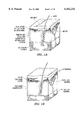
- FIGS. 2A-2B are views of different sizes of Type "A" handpiece bodies of the present invention.
- FIGS. 3A-3B are enlarged sectional views of the handpiece bodies of FIGS. 2A-2B take along lines 3A--3A and 3B--3B rotated 90°.
- FIG. 4 is perspective view of a duct component of either body of FIGS. 3A-3B.
- FIGS. 5A-5B are views of alternative embodiments of the duct component of FIG. 4.
- FIGS. 6A-6B are views of alternative embodiments of a handpiece similar to that shown in FIG. 2B.
- FIG. 7 is an enlarged view of the working end of the device of FIG. 2B.
- FIG. 8 is a view of the duct component of FIG. 4 showing an exemplary energy delivery pattern over a treatment area of a patient's skin.
- FIGS. 9A-9B are views showing the manner of using the working end of the invention to perform a method of the invention; FIG. 9A showing a treatment area received by an opening portion in the working end of the device of FIG. 7 under aspiration pressures; FIG. 9B depicting the skin being exfoliated in the treatment area by high-velocity gas flows and crystal abrasives.
- the instrument system 5 includes: (i) a hand-held body 8 (comprising first and second body components 8A and 8B) having a skin interface surface indicated at 15 with an opening portion 22 that extends to interior chamber portion 24 to interface with a treatment area TA of a patient's skin, and (ii) delivery means for introducing (A) high-pressure gas streams and (B) cooling/abrasive fluid flows to the working end of the body 8 together with (C) vacuum means for aspirating skin debris from the targeted treatment area TA.
- a hand-held body 8 comprising first and second body components 8A and 8B having a skin interface surface indicated at 15 with an opening portion 22 that extends to interior chamber portion 24 to interface with a treatment area TA of a patient's skin
- delivery means for introducing (A) high-pressure gas streams and (B) cooling/abrasive fluid flows to the working end of the body 8 together with (C) vacuum means for aspirating skin debris from the targeted treatment area TA.
- the instrument system 5 includes a computer controller 25 that controls media flows from the various sources or reservoirs (the term media is used interchangeably herein with the term fluid, and is defined as any composition that is capable of flowing, i.e., a liquid or a gas, and that is used to strike the skin and assist in the exfoliation of skin layers).
- a 1 st delivery means comprising a gas source or reservoir indicated at 30 is provided to introduce high-pressure media flows through duct component SB to develop high-pressure gas streams 36A and 36B in interior chamber (see FIGS. 3A-3B and FIG. 4).
- a 2 nd delivery means comprising a media reservoir or source indicated at 40 is provided to introduce a cooling fluid CF carrying crystal abrasives CA into interior chamber 24 to intermix with the high-pressure gas streams 36A and 36B.
- This invention offers several advantages by using an independent low-pressure 2 nd delivery means 40 for introducing the abrasive-carrying media into interior chamber 24 under very low pressures, or the absence of pressure.
- the advantages follow: First, it has been found that delivery of a liquid against the epidermis during micro-dermabrasion reduces the patient's sensation of pain. It is believed the reduction in pain is caused mostly by the liquid absorbing and conducting heat away from the treatment area TA. This factor allows the system to use higher velocity gas streams and finer crystalline abrasives to provide a very fine dermabrasion treatment that would far exceed the patient's pain threshold without the use of a cooling fluid.
- the use of low-pressure introduction (or no pressure introduction as described below) of crystal abrasives CA in a fluid allows such a fluid flow to be terminated abruptly to prevent abrasive crystals from flowing into the operating environment after the working (skin-interface) surface 15 is lifted away from the patient's skin.
- a fluid fluid being defined as flowable medium, i.e., liquid or gas
- an crystalline abrasive-laden fluid such as sterile water, allows the water to essentially atomize into water droplets as it intermixes with the high-velocity gas streams 36A-36B to allow the abrasive crystals to strike and abrade the skin (FIG. 4).
- the body 8 of the invention is scalable to various sizes to provide different treatment dimensions by providing a smaller or larger open portion 22, for example in the exemplary bodies 8 shown in FIGS. 2A-2B.
- the body 8 of FIG. 2A is of a large size for gripping between the fingers of the operator or in the palm of the operator.
- the body 8 of FIG. 2B is of a smaller size for a pen-like grip between the operator's fingers.
- FIGS. 2A-2B are provided with first and second de-matable body components 8A and 8B, which are illustrated in FIGS. 3A-3B.
- the (first) tissue-interface body component is indicated at 8A.
- the (second) fluid-flow duct component is indicated at 8B and is adapted to slidably fit into a cooperating receiving slot 41A in tissue-interface body 8A with cooperating keyways 41B in the bodies 8A and 8B adapted to align the components.
- FIG. 4 is a perspective view an exemplary duct component 8B which shows flexible gas supply tubing 42a-42b attached thereto as well as cooling fluid tubing 43.
- duct components 8B may be configured with particular duct dimensions for accelerating gas flows therethrough or for laterally-distributing gas streams to optimize various skin treatment parameters, and the de-matable aspect of component 8B allows it to be switched out quickly from a cooperating body component 8A;
- a duct component 8B that is de-matable may be injection molded in an inexpensive manner and may be disposable along with the supply tubing;
- a duct component 8B in some applications may require cleaning and the disclosed de-matable component 8B facilitates its switching out for cleaning or replacement; and
- a particular duct component 8B may switched between different side-interface bodies 8A to select an optimal angle-of-attack of high-pressure gas streams against the skin (described further below) which is determined by body 8A.
- FIGS. 4 & 5A-5B show alternative duct-carrying components 8B that are configured with one or more of flow ducts 44a-44c, with each duct defining a corresponding flow axis 45a-45c, with duct dimensions and parameters that are described in detail below.
- FIGS. 5A-8B show that multiple coolant inflow passageways fall within the scope of the invention.
- FIGS. 6A-6B show alternative skin-interface bodies 8A with variously angled surfaces 15, each example of which has a receiving slot 41A that is adapted to receive any particular duct component 8B, for instance any of the exemplary components 8B of FIGS. 4 & 5A-5B. As can be seen in FIGS. 3A-3B and FIGS.
- the skin interface surface 15 about open portion 22 defines a particular angle-of-attack ⁇ of high-velocity gas streams against the surface of the skin, which generally is the angle of slot 41A relative to skin interface surface 15.
- ⁇ the angle of slot 41A relative to skin interface surface 15.
- lower angles-of-attack of fluid and/or agent flows against the skin causes less sensation of pain than higher angles-of attack, and that various areas of skin on a patient's body (as well as various skin types) have differing pain thresholds.
- higher flow velocities are permitted at lower angles-of-attack for a given level of pain sensation.
- the bodies 8A can be configured with a receiving slot 41A at a selected angle ⁇ to optimize the angle-of-attack via fluid flow ducts 44a-44c and about fluid flow axes 45a-45c.
- a preferred embodiment of the body 8 defines angle ⁇ within a range from about 0 to 40°. More preferably, the body 8 defines angle ⁇ within a range from about 5° to 25°.
- FIG. 7 shows an enlarged sectional view of an open end portion of a body 8 (either body of FIGS. 2A-2B) with a skin-interface opening portion 22 surrounded by a surface area indicated at 15.
- Surface 15 around opening portion 22 preferably is smooth with a lubricious coating (e.g., Teflon® coating) to slide easily over the skin's surface.
- the body 8A is of any suitable transparent material, such as a transparent medical grade plastic. The transparency of body 8A will assist the operator in localizing treatment in a particular targeted skin treatment area.
- the transverse dimension of body 8A of FIGS. 2A-2B around opening portion 22 may vary from about 5.0 mm. to 50.0 mm.
- a typical dimension is from about 5.0 mm. to 15.0 mm. for a treatment area TA around a patient's face.
- FIGS. 4 and 7 further shows exemplary ducts 44a-44b that have a minimal-dimension proximal jet portions 50a-50b and distal duct portions 54a-54b that are adapted to shape the gas flow streams therethrough and beyond as the gas streams 36A-36B spread into interior chamber 24.
- FIG. 4 shows that the shape of ducts 44a-44b have length l and width w height dimension h in the distal duct portion thereof (54a-54b) which communicate with interior the chamber portion 24 proximate to opening 22.
- the distal terminations 54a-54b of the ducts 44a-44b have a collective width w that may be defined angularly relative to opening 22 and collectively cover from about 45° to about 270° around opening 22 (see FIGS. 4 & 5A).
- the height dimension h of any distal termination 54a-54b of a duct 44a-44b preferably ranges from about 0.1 mm. to 4.0 mm. to provide means for spreading the air flow over a wider surface area and for creating an even distribution of fluid flow pressure over a treatment area TA of skin (see FIG. 8).
- height dimension h ranges from about 0.5 mm. to 2.0 mm.
- FIG. 4 further shows that jet portions 50a-50b preferably have a rectangular or elongate slit-type configuration but a pin-hole type aperture also may be suitable at the proximal end of each duct. These duct configurations and dimensions allow the hi-velocity gas streams 36A-36B to be flattened with an energy density spread evenly over the treatment area TA of the epidermis received by opening 22 (see FIG. 8).
- This aspect of the invention is an improvement over prior art devices that jet abrasives against the skin from a pin-hole jet that covered little surface area.
- FIG. 8 shows an exemplary duct component 8B that causes gas streams to be spread laterally to cover a wide treatment areas TA with an even energy distribution.
- the wide treatment TA area is allowed by both (or either, individually), (i) at least one laterally-distributed or flattened gas stream relative to its flow axis, and (ii) a plurality of partly overlapping gas streams to thus allow an even energy distribution within a scalable working end of the device.
- FIG. 8 shows an outline of opening 22 within face 15.
- the invention allows the dimensions of opening 22 to be in any shape and circumscribe an area ranging from about 5 mm. in diameter (or equivalent non-circular area) to about 40 mm. in diameter (or an equivalent non-circular area).
- FIG. 8 shows that opening 22 has a somewhat elliptical shape in the exemplary embodiment.
- body 8A defines interior chamber 24 therein that communicates with passageway 56 that is connected to a flexible aspiration tube 58 that extends to a remote collection reservoir 60.
- FIGS. 9A-9B show that opening 22 is adapted to partially receive the surface skin layers of a treatment area TA.
- the skin-interface surface 15 defines plane P and has a width dimension 62 that is sufficient to allow the face 15 to be supported on, and slide over, the skin's surface when negative pressurization exists in chamber 24. More particularly, the width dimension 62 of surface 15 ranges from about 1.0 mm. to 5.0 mm., and may be increased in width at heel portion 63.
- interior chamber 24 of body 8A directly communicates with the two ducts 44a and 44b that are adapted to deliver a gas under pressure from 1 st delivery source 30 to interior chamber 24.
- the number of such ducts or passageways may range from one to about ten and fall within the scope of the invention.
- gas as used herein describes any suitable gas, but preferably is a medical grade CO 2 supplied in a pressurized tank for reasons described below. (It should be appreciated that compressed air also may be suitable; delivered either from a pressurized tank or a compressor).
- the system is adapted to provide gas inflow pressures from the 1 st delivery means 30 that range from about 5 psi to 125 psi on the proximal side of jet portions 50a-50c of any ducts in body component 8B.
- the 2 nd delivery means 40 introduces the coolant fluid CF plus a crystalline agent CA into chamber 24 to intermix with the high-pressure gas streams 36A-36B provided by the 1 st delivery means, to thereafter impact the skin surface to abrade away superficial layers.
- a small diameter flexible supply tube 43 is best seen in FIG. 4 connected to bore 64 in body portion 8B.
- bore 64 is very small in diameter (e.g., 0.005" to 0.10" diameter).
- the fluid CF plus agent CA is carried in a reservoir that may be pressurized or unpressurized.
- the source or reservoir may be a pressurized vessel (or pressure source) fitted with a regulator 65 (not shown) as is known in the art to introduce a sterile fluid and crystalline agent into interior chamber 24.
- a pressurized vessel or pressure source
- a regulator 65 not shown
- any sort of pump or pressure system may be used to supply fluid CF plus agent CA to the interior chamber 24 such as a peristaltic pump or another fluid pump type known in the art.
- any mechanism known in the art may be used such as a vibratory mechanism. As indicated in FIG.
- the system 5 may optionally have a thermal energy system 70 for altering the temperature of fluid CF to any temperature below the patient's body temperature, that is within a range from about 0° C. to about 38° C.
- the temperature of the fluid CF is from about 0 ° C. to about 35° C.
- a temperature range of fluid CF between about 5° C. to about 25° C.
- Any type of a thermal energy system 70 that is known in the art may be used to remove heat from (or apply heat to) the fluid CF, and a preferred system would use thermoelectric cooling (or heating) using bismuth telluride semi-conductors in the manner commercialized by Melcor Corp., 1040 Spruce Street, Trenton, N.J. 08641A.
- the coolant fluid CF is further provided with a selected amount of crystalline agent CA mixed therein, which may be any suitable crystalline substance such as aluminum oxide.
- crystalline agent CA may be any suitable crystalline substance such as aluminum oxide.
- the invention disclosed herein may be use with crystals ranging is size from about 1 ⁇ m to about 30 ⁇ m in maximum cross-sectional dimension. Preferably, the crystals are from about 5 ⁇ m to about 15 ⁇ m in maximum cross-sectional dimension to allow a very fine abrasion of the epidermis.
- the use of such fine crystals was not feasible with prior art equipment for two reasons: First, such fine crystals would cause too much pain to the patient, which aspect of the prior art is overcome by the cooling system of the present invention.
- the negative (-) pressurization means or vacuum source 80 is provided which communicates with interior chamber 24 in body 8A for evacuating skin debris and spent fluid CF plus agent CA from the treatment site TA.
- flexible tube 58 extends from interior chamber 24 to a collection reservoir 60.
- the negative (-) pressurization source 80 may be any suitable vacuum source known in the art.
- a filter 84 subsystem that is known in the art for collecting aspirated fluid CF plus agent CA and skin detritus that is captured by the negative pressure in chamber 24.
- the collection reservoir 60 and filter 84 are of inexpensive plastic and other materials that are disposable.
- FIGS. 2A-2B illustrate that the negative (-) pressurization source 80 and the 1 st and 2 nd delivery means 30 and 40 are provided with adjustable valve means 85a, 85b and 85c for adjusting the pressure level setting, and balance between, the various fluid delivery sources and the negative (-) pressurization source 80.
- the physician will learn from experience how to balance the pressure levels from the cooperating pressurization sources to jet chemical agents and collect such spent agents without suctioning skin too tightly against the treatment areas TA.
- the computer controller 25 will be provided with algorithms to automatically balance fluid flow pressures and aspiration pressures, as well as with algorithms for any dimensions of ducts within component 8B.
- a trigger or switch component 88 is provided for sequentially (or otherwise) actuating the 1 st and 2 nd delivery means or sources 30 and 40, and the negative (-) pressurization source 80.
- the trigger mechanism 88 (handswitch or footswitch) has a repose OFF position and a 1 st ON position and a 2 nd ON position.
- the 1 st position actuates the 1 st delivery means 30 and negative pressure source 80 to thereby jet gases through the interior chamber and aspirate the gases.
- the 2 nd ON position of the trigger 88 actuates the 2 nd delivery means 40 to deliver cooling fluid CF and crystal agent CA into the gas streams 36A-36B and against the patient's skin while still actuating the 1 st and 2 nd delivery means.
- the trigger mechanism 88 preferably is differently sequentially timed (i) when moving the switch to the 2 nd On position from the OFF position, and (ii) when moving the switch from the 2 nd ON position to the OFF position similar to manner described in patent application Ser. No. 09/271,610 filed Mar. 17, 1999 titled Technique and System for Controlled Chemically-Mediated Removal of Skin Layers.
- a fluid CF is selected and the controller 25 of system 5 is programmed to maintain the fluid CF at a particular temperature.
- the fluid is also selected to carry a particular dimension (or grit) of abrasive crystal CA.
- the operator (after cleansing the patient's skin) places the surface 15 of body 8A on the patient's skin and moves the trigger mechanism 88 to a 1 st position thereby actuating the negative (-) pressure source 80 to draw the tissue surface against or into opening 22.
- the switch actuates the 1 st delivery means 30 to cause CO 2 gas (or another gas) to be jetted through apertures 50a-50b and ducts 44a-44b into interior chamber 24.
- the negative (-) pressure source 80 captures and aspirates the gas stream 36A-36B of the 1 st delivery means 40 after the gas stream strikes the skin surface in the interior chamber 24. It is believed that only an independent and computer-controlled aspiration pressure source 80 will allow the use of large diameter openings 22 in the working end of body 8 to substantially draw the skin upward into the opening 22 to thus allow the wide paths of treatment described above.
- the operator then moves the trigger mechanism 88 to a 2 nd position that actuates the 2 nd fluid delivery means 40 to allow low-pressure or no pressure flow of cooling fluid CF and crystalline agent CA into interior chamber to mix with high-velocity gas streams 36A and 36B as shown in FIG. 9B.
- the flow of fluid CF and crystalline agent CA optionally may be triggered automatically a pre-selected time interval after the movement of the trigger to the 1 st position).
- the mixing of the crystalline agent CA with the high-velocity air streams proves to be an economical and efficient manner to cause a fine abrasion of the epidermis.
- the flow of atomized fluid cools the skin as described above which reduces or eliminates the sensation of pain. As can be seen in FIG.
- the negative (-) pressure source aspirates the spent fluids and skin detritus from the interior chamber 24.
- operator can instantly terminate the low pressure flow of fluid CF and crystal CA to stop the flow of cooling fluid CF and crystalline agent CA so to prevent contamination of the environment when body 8 is removed from the patient's skin.
- the operator While maintaining the trigger mechanism in the 2 nd position, the operator then sweeps the working face 15 over the patient's skin to exfoliate a path therein. At the end of a sweep, the operator releases the trigger 88 which in sequence terminates the 2 nd delivery means 40, then the 1 st delivery means and then a slight time interval later terminates the negative (-) pressure source 80 to allow the operator to easily lift the body from the patient's skin.
- the exfoliated path can be seen and the operator then can exfoliate another slightly overlapping or adjacent path by repeating the above steps until exfoliation is completed over the treatment area.
- the system 5 of the invention is commercialized as a kit with instructions for use that include the following.
- the steps in the instructions first explain to select a desired temperature of cooling fluid CF for a particular dermabrasion, and to select a particular grit size of crystal abrasive CA.
- the instructions further explain to select a particular pressure for gas inflows from 1 st delivery means ranging from about 5 psi to 125 psi.
- the instructions further explain to select a particular negative pressure for aspiration of spent fluids and skin debris from the interior chamber 24.
- the instructions then direct the operator (after cleansing the patient's skin) to press the surface 15 of the body 8A on the skin of the patient in the treatment area TA.
- the instructions for operating the system then direct the operator to actuate the trigger mechanism 88 to a 1 st position to cause the high velocity gas streams to be jetted against the skin by the 1 st delivery means, while at the same time the negative (-) pressure source 80 is activated to aspirate debris from chamber 24 into the collection reservoir.
- the operating instructions further direct the operator to thereafter move the trigger to a 2 nd position to actuate the low-pressure cooling fluid and crystalline agent delivery means 40, and to sweep the working face 15 over the patient's skin to abrade the epidermis in a path.
- the operator is instructed to release the trigger to the release position to terminate fluid flows, that is cooling fluid CF and crystalline agent CA and the high velocity gas streams, and negative pressure in sequence to allow lifting of the body from the patient's skin.
- the operating instructions further direct the operator to repeat the above steps to abrade superficial layers in slightly overlapping or adjacent paths to controllably remove superficial layers in the treatment area.
- the instructions then direct the operator to dispose of the aspirated and collected skin detritus and spent fluids and crystalline agent.
Abstract
Description
Claims (32)
Priority Applications (1)
| Application Number | Priority Date | Filing Date | Title |
|---|---|---|---|
| US09/294,254 US6162232A (en) | 1999-03-18 | 1999-04-19 | Instruments and techniques for high-velocity fluid abrasion of epidermal layers with skin cooling |
Applications Claiming Priority (3)
| Application Number | Priority Date | Filing Date | Title |
|---|---|---|---|
| US12536999P | 1999-03-18 | 1999-03-18 | |
| US12539999P | 1999-03-20 | 1999-03-20 | |
| US09/294,254 US6162232A (en) | 1999-03-18 | 1999-04-19 | Instruments and techniques for high-velocity fluid abrasion of epidermal layers with skin cooling |
Publications (1)
| Publication Number | Publication Date |
|---|---|
| US6162232A true US6162232A (en) | 2000-12-19 |
Family
ID=27383234
Family Applications (1)
| Application Number | Title | Priority Date | Filing Date |
|---|---|---|---|
| US09/294,254 Expired - Lifetime US6162232A (en) | 1999-03-18 | 1999-04-19 | Instruments and techniques for high-velocity fluid abrasion of epidermal layers with skin cooling |
Country Status (1)
| Country | Link |
|---|---|
| US (1) | US6162232A (en) |
Cited By (93)
| Publication number | Priority date | Publication date | Assignee | Title |
|---|---|---|---|---|
| US6299620B1 (en) * | 1999-03-18 | 2001-10-09 | Aq Technologies, Inc. | Instruments and techniques for inducing neocollagenesis in skin treatments |
| US6387103B2 (en) * | 1999-12-30 | 2002-05-14 | Aq Technologies, Inc. | Instruments and techniques for inducing neocollagenesis in skin treatments |
| US6432114B1 (en) * | 1999-06-16 | 2002-08-13 | L.I.C.A. S.R.L. | Device for making hydro-microabrasions on human tissue |
| WO2002098288A2 (en) * | 2001-06-07 | 2002-12-12 | Fallon, James | Hand piece for use in a dermal abrasion system |
| US20030093040A1 (en) * | 2001-10-29 | 2003-05-15 | Mikszta John A. | Method and device for the delivery of a substance |
| US6629983B1 (en) * | 2000-10-27 | 2003-10-07 | Edge Systems Corporation | Apparatus and method for skin/surface abrasion |
| US6641591B1 (en) * | 1999-08-26 | 2003-11-04 | John H. Shadduck | Instruments and techniques for controlled removal of epidermal layers |
| US20030208159A1 (en) * | 2002-03-01 | 2003-11-06 | Ignon Roger G. | Skin abrasion growth factor fluid delivery system and method |
| US20030212415A1 (en) * | 2001-11-21 | 2003-11-13 | Karasiuk Kenneth B. | Skin treatment system and method of use |
| US20040260210A1 (en) * | 2003-06-23 | 2004-12-23 | Engii (2001) Ltd. | System and method for face and body treatment |
| US20040260209A1 (en) * | 2003-06-23 | 2004-12-23 | Engli (2001) Ltd. | System and method for face and body treatment |
| US20060047291A1 (en) * | 2004-08-20 | 2006-03-02 | Uptake Medical Corporation | Non-foreign occlusion of an airway and lung collapse |
| US20060058723A1 (en) * | 2004-09-15 | 2006-03-16 | Pratt William R | Apparatus and method for cleaning a surgically prepared bone surface |
| US20060100567A1 (en) * | 2004-07-30 | 2006-05-11 | Rocky Mountain Biosystems, Inc | Microsurgical tissue treatment system |
| US20060161233A1 (en) * | 2004-11-16 | 2006-07-20 | Uptake Medical Corp. | Device and method for lung treatment |
| US20060253125A1 (en) * | 2005-03-07 | 2006-11-09 | Ignon Roger G | Microdermabrasion method and apparatus |
| US20070043382A1 (en) * | 2005-08-18 | 2007-02-22 | Cheney Sharon A | Thermal separation of impurities from the scalp, hair, and skin |
| US20080110457A1 (en) * | 2006-11-13 | 2008-05-15 | Uptake Medical Corp. | Treatment with high temperature vapor |
| US20080114297A1 (en) * | 2006-11-13 | 2008-05-15 | Uptake Medical Corp. | High pressure and high temperature vapor catheters and systems |
| US20080132826A1 (en) * | 2003-01-18 | 2008-06-05 | Shadduck John H | Medical instruments and techniques for treating pulmonary disorders |
| US7494482B2 (en) | 2001-05-15 | 2009-02-24 | The Brigham And Women's Hospital, Inc. | Methods and apparatus for application of micro-mechanical forces to tissues |
| US20090062815A1 (en) * | 2007-08-28 | 2009-03-05 | Emed, Inc. | Handheld microdermabrasion device |
| US20090194164A1 (en) * | 2008-02-05 | 2009-08-06 | Twin Creeks Technologies, Inc. | Method to form a photovoltaic cell comprising a thin lamina |
| US7691102B2 (en) * | 2006-03-03 | 2010-04-06 | Covidien Ag | Manifold for gas enhanced surgical instruments |
| US8016823B2 (en) | 2003-01-18 | 2011-09-13 | Tsunami Medtech, Llc | Medical instrument and method of use |
| US8048089B2 (en) | 2005-12-30 | 2011-11-01 | Edge Systems Corporation | Apparatus and methods for treating the skin |
| US8147532B2 (en) | 2007-10-22 | 2012-04-03 | Uptake Medical Corp. | Determining patient-specific vapor treatment and delivery parameters |
| US8157807B2 (en) | 2005-06-02 | 2012-04-17 | The Invention Science Fund I, Llc | Skin treatment including patterned light |
| US20120165725A1 (en) * | 2010-12-22 | 2012-06-28 | Cabochon Aesthetics, Inc. | Dissection handpiece with aspiration means for reducing the appearance of cellulite |
| US8236008B2 (en) | 2008-02-29 | 2012-08-07 | Envy Medical, Inc. | Microdermabrasion treatment heads |
| US8322335B2 (en) | 2007-10-22 | 2012-12-04 | Uptake Medical Corp. | Determining patient-specific vapor treatment and delivery parameters |
| US8343116B2 (en) | 2008-01-04 | 2013-01-01 | Edge Systems Corporation | Apparatus and method for treating the skin |
| US8444636B2 (en) | 2001-12-07 | 2013-05-21 | Tsunami Medtech, Llc | Medical instrument and method of use |
| US8574226B2 (en) | 2000-12-09 | 2013-11-05 | Tsunami Medtech, Llc | Method for treating tissue |
| US8579888B2 (en) | 2008-06-17 | 2013-11-12 | Tsunami Medtech, Llc | Medical probes for the treatment of blood vessels |
| US8579892B2 (en) | 2003-10-07 | 2013-11-12 | Tsunami Medtech, Llc | Medical system and method of use |
| US8579893B2 (en) | 2005-08-03 | 2013-11-12 | Tsunami Medtech, Llc | Medical system and method of use |
| US8721632B2 (en) | 2008-09-09 | 2014-05-13 | Tsunami Medtech, Llc | Methods for delivering energy into a target tissue of a body |
| US8753339B2 (en) | 2005-09-07 | 2014-06-17 | Ulthera, Inc. | Dissection handpiece and method for reducing the appearance of cellulite |
| US8814836B2 (en) | 2008-01-29 | 2014-08-26 | Edge Systems Llc | Devices, systems and methods for treating the skin using time-release substances |
| US20140343574A1 (en) * | 2006-03-29 | 2014-11-20 | Edge Systems Llc | Devices, systems and methods for treating the skin |
| US8900223B2 (en) | 2009-11-06 | 2014-12-02 | Tsunami Medtech, Llc | Tissue ablation systems and methods of use |
| US9011473B2 (en) | 2005-09-07 | 2015-04-21 | Ulthera, Inc. | Dissection handpiece and method for reducing the appearance of cellulite |
| US9050133B1 (en) | 2009-12-22 | 2015-06-09 | Envy Medical, Inc. | Skin treatment system with adjustable height wand |
| US9056193B2 (en) | 2008-01-29 | 2015-06-16 | Edge Systems Llc | Apparatus and method for treating the skin |
| US9161801B2 (en) | 2009-12-30 | 2015-10-20 | Tsunami Medtech, Llc | Medical system and method of use |
| US9248317B2 (en) | 2005-12-02 | 2016-02-02 | Ulthera, Inc. | Devices and methods for selectively lysing cells |
| US9272124B2 (en) | 2005-12-02 | 2016-03-01 | Ulthera, Inc. | Systems and devices for selective cell lysis and methods of using same |
| US9358033B2 (en) | 2005-09-07 | 2016-06-07 | Ulthera, Inc. | Fluid-jet dissection system and method for reducing the appearance of cellulite |
| US9358064B2 (en) | 2009-08-07 | 2016-06-07 | Ulthera, Inc. | Handpiece and methods for performing subcutaneous surgery |
| US9433457B2 (en) | 2000-12-09 | 2016-09-06 | Tsunami Medtech, Llc | Medical instruments and techniques for thermally-mediated therapies |
| US9486274B2 (en) | 2005-09-07 | 2016-11-08 | Ulthera, Inc. | Dissection handpiece and method for reducing the appearance of cellulite |
| US9498610B2 (en) | 2014-12-23 | 2016-11-22 | Edge Systems Llc | Devices and methods for treating the skin using a rollerball or a wicking member |
| US9561068B2 (en) | 2008-10-06 | 2017-02-07 | Virender K. Sharma | Method and apparatus for tissue ablation |
| US9561067B2 (en) | 2008-10-06 | 2017-02-07 | Virender K. Sharma | Method and apparatus for tissue ablation |
| US9561066B2 (en) | 2008-10-06 | 2017-02-07 | Virender K. Sharma | Method and apparatus for tissue ablation |
| US20170181769A1 (en) * | 2015-12-28 | 2017-06-29 | Dominique Calhoun | Dermal Abrasion System |
| US9700365B2 (en) | 2008-10-06 | 2017-07-11 | Santa Anna Tech Llc | Method and apparatus for the ablation of gastrointestinal tissue |
| US9782211B2 (en) | 2013-10-01 | 2017-10-10 | Uptake Medical Technology Inc. | Preferential volume reduction of diseased segments of a heterogeneous lobe |
| US9833261B2 (en) | 2008-08-22 | 2017-12-05 | Envy Medical, Inc. | Microdermabrasion system upgrade kit |
| US9924992B2 (en) | 2008-02-20 | 2018-03-27 | Tsunami Medtech, Llc | Medical system and method of use |
| US9943353B2 (en) | 2013-03-15 | 2018-04-17 | Tsunami Medtech, Llc | Medical system and method of use |
| US10064697B2 (en) | 2008-10-06 | 2018-09-04 | Santa Anna Tech Llc | Vapor based ablation system for treating various indications |
| TWI637707B (en) * | 2016-07-25 | 2018-10-11 | 艾倫 丹托 | Positive pressure flow skin abrasion system |
| US10172644B2 (en) | 2006-03-29 | 2019-01-08 | Edge Systems Llc | Devices, systems and methods for treating the skin |
| US10179229B2 (en) | 2014-12-23 | 2019-01-15 | Edge Systems Llc | Devices and methods for treating the skin using a porous member |
| US10179019B2 (en) | 2014-05-22 | 2019-01-15 | Aegea Medical Inc. | Integrity testing method and apparatus for delivering vapor to the uterus |
| US10238812B2 (en) | 2013-03-15 | 2019-03-26 | Edge Systems Llc | Skin treatment systems and methods using needles |
| US10238446B2 (en) | 2010-11-09 | 2019-03-26 | Aegea Medical Inc. | Positioning method and apparatus for delivering vapor to the uterus |
| USD845467S1 (en) | 2017-09-17 | 2019-04-09 | Uptake Medical Technology Inc. | Hand-piece for medical ablation catheter |
| US10299856B2 (en) | 2014-05-22 | 2019-05-28 | Aegea Medical Inc. | Systems and methods for performing endometrial ablation |
| US10485983B1 (en) | 2008-08-22 | 2019-11-26 | Envy Medical, Inc. | Microdermabrasion system with combination skin therapies |
| US10485604B2 (en) | 2014-12-02 | 2019-11-26 | Uptake Medical Technology Inc. | Vapor treatment of lung nodules and tumors |
| US10531906B2 (en) | 2015-02-02 | 2020-01-14 | Uptake Medical Technology Inc. | Medical vapor generator |
| US10548659B2 (en) | 2006-01-17 | 2020-02-04 | Ulthera, Inc. | High pressure pre-burst for improved fluid delivery |
| US10695126B2 (en) | 2008-10-06 | 2020-06-30 | Santa Anna Tech Llc | Catheter with a double balloon structure to generate and apply a heated ablative zone to tissue |
| US10758292B2 (en) | 2007-08-23 | 2020-09-01 | Aegea Medical Inc. | Uterine therapy device and method |
| US10881442B2 (en) | 2011-10-07 | 2021-01-05 | Aegea Medical Inc. | Integrity testing method and apparatus for delivering vapor to the uterus |
| US10993743B2 (en) | 2013-03-15 | 2021-05-04 | Edge Systems Llc | Devices, systems and methods for treating the skin |
| US11096708B2 (en) | 2009-08-07 | 2021-08-24 | Ulthera, Inc. | Devices and methods for performing subcutaneous surgery |
| US11129673B2 (en) | 2017-05-05 | 2021-09-28 | Uptake Medical Technology Inc. | Extra-airway vapor ablation for treating airway constriction in patients with asthma and COPD |
| US11241357B2 (en) | 2015-07-08 | 2022-02-08 | Edge Systems Llc | Devices, systems and methods for promoting hair growth |
| US11284931B2 (en) | 2009-02-03 | 2022-03-29 | Tsunami Medtech, Llc | Medical systems and methods for ablating and absorbing tissue |
| US11331037B2 (en) | 2016-02-19 | 2022-05-17 | Aegea Medical Inc. | Methods and apparatus for determining the integrity of a bodily cavity |
| US11331140B2 (en) | 2016-05-19 | 2022-05-17 | Aqua Heart, Inc. | Heated vapor ablation systems and methods for treating cardiac conditions |
| US11344364B2 (en) | 2017-09-07 | 2022-05-31 | Uptake Medical Technology Inc. | Screening method for a target nerve to ablate for the treatment of inflammatory lung disease |
| US11350988B2 (en) | 2017-09-11 | 2022-06-07 | Uptake Medical Technology Inc. | Bronchoscopic multimodality lung tumor treatment |
| US11419658B2 (en) | 2017-11-06 | 2022-08-23 | Uptake Medical Technology Inc. | Method for treating emphysema with condensable thermal vapor |
| US11490946B2 (en) | 2017-12-13 | 2022-11-08 | Uptake Medical Technology Inc. | Vapor ablation handpiece |
| EP4147669A1 (en) * | 2021-08-31 | 2023-03-15 | TAV-TECH Ltd. | Dermal infusion handpiece with improved delivery head |
| US11653927B2 (en) | 2019-02-18 | 2023-05-23 | Uptake Medical Technology Inc. | Vapor ablation treatment of obstructive lung disease |
| US11806066B2 (en) | 2018-06-01 | 2023-11-07 | Santa Anna Tech Llc | Multi-stage vapor-based ablation treatment methods and vapor generation and delivery systems |
| USD1016615S1 (en) | 2021-09-10 | 2024-03-05 | Hydrafacial Llc | Container for a skin treatment device |
Citations (24)
| Publication number | Priority date | Publication date | Assignee | Title |
|---|---|---|---|---|
| DE234608C (en) * | ||||
| US2608032A (en) * | 1950-08-29 | 1952-08-26 | Pangborn Corp | Suction blast gun |
| US2921585A (en) * | 1955-07-01 | 1960-01-19 | Reinhold S Schumann | Device for the treatment of skin diseases such as skin overgrowths, eruptions and the like or other skin disfigurements |
| US3085573A (en) * | 1960-03-15 | 1963-04-16 | Jerome H Meyer | Cleansing apparatus |
| US3476122A (en) * | 1967-11-29 | 1969-11-04 | Attilio Zaupa | Hairpiece |
| US3574239A (en) * | 1968-01-12 | 1971-04-13 | Svenska Utvecklings Ab | Apparatus for washing patients hygienically |
| US3715838A (en) * | 1970-03-06 | 1973-02-13 | Vacu Blast Ltd | Apparatus for correcting misprinted matter on sheet material |
| US4182329A (en) * | 1977-05-31 | 1980-01-08 | Smit Helen E | Acne facial treatment appliance and method |
| US4216233A (en) * | 1978-12-06 | 1980-08-05 | Stein Karl N | Method for treatment of skin burns in mammals |
| DE3421390A1 (en) * | 1984-06-08 | 1985-12-12 | Werner Dr.med. 4330 Mülheim Schubert | High-pressure catheter with a cutting and/or abrasion device |
| US4560373A (en) * | 1983-06-06 | 1985-12-24 | Sugino Machine Limited | Surgical nozzle apparatus |
| US4646480A (en) * | 1985-10-23 | 1987-03-03 | Inventive Machine Corporation | Pressurized abrasive cleaning device for use with plastic abrasive particles |
| US4676749A (en) * | 1984-03-08 | 1987-06-30 | Ems Electro Medical Systems, S.A. | Nozzle head for the hand piece of a dental prophylactic apparatus |
| US4706676A (en) * | 1985-02-11 | 1987-11-17 | The United States Of America As Represented By The Secretary Of The Army | Dermal substance collection device |
| EP0258901A2 (en) * | 1986-09-03 | 1988-03-09 | Tonokura Ika Kogyo Co. Ltd | Water jet operating apparatus and liquid supply unit line used for the apparatus |
| US4757814A (en) * | 1985-02-28 | 1988-07-19 | Alcon Laboratories, Inc. | Proportional control for pneumatic cutting device |
| US4900316A (en) * | 1986-10-18 | 1990-02-13 | Azz International Co., Ltd. | Vacuum skin cleaner |
| US5037432A (en) * | 1987-11-27 | 1991-08-06 | Lorenzo Molinari | Adjustable apparatus for removing surface portions of human tissue |
| US5100412A (en) * | 1988-01-11 | 1992-03-31 | L.I.C.A. Di Rosso & C. S.N.C. | Apparatus for making micro-abrasions, particularly on human tissue or on hides |
| US5207234A (en) * | 1988-01-11 | 1993-05-04 | L.I.C.A. Di Rosso & C.S. N.C. | Method for making micro-abrasions on human tissue |
| US5810842A (en) * | 1994-06-29 | 1998-09-22 | Mattioli Engineering S.R.L. | Equipment for microdermoabrasion through a flow of an air/reducing substances mix |
| US5971999A (en) * | 1995-06-16 | 1999-10-26 | Naldoni; Moreno | Apparatus for microdermabrasion by means of a jet of mixture of air/reducing substances and relating handle |
| US6024733A (en) * | 1995-06-07 | 2000-02-15 | Arthrocare Corporation | System and method for epidermal tissue ablation |
| US6039745A (en) * | 1995-06-29 | 2000-03-21 | Mattioli Engineering Ltd. | Equipment for microdermoabrasion through a flow of air/reducing substances mix and relative handpiece |
-
1999
- 1999-04-19 US US09/294,254 patent/US6162232A/en not_active Expired - Lifetime
Patent Citations (24)
| Publication number | Priority date | Publication date | Assignee | Title |
|---|---|---|---|---|
| DE234608C (en) * | ||||
| US2608032A (en) * | 1950-08-29 | 1952-08-26 | Pangborn Corp | Suction blast gun |
| US2921585A (en) * | 1955-07-01 | 1960-01-19 | Reinhold S Schumann | Device for the treatment of skin diseases such as skin overgrowths, eruptions and the like or other skin disfigurements |
| US3085573A (en) * | 1960-03-15 | 1963-04-16 | Jerome H Meyer | Cleansing apparatus |
| US3476122A (en) * | 1967-11-29 | 1969-11-04 | Attilio Zaupa | Hairpiece |
| US3574239A (en) * | 1968-01-12 | 1971-04-13 | Svenska Utvecklings Ab | Apparatus for washing patients hygienically |
| US3715838A (en) * | 1970-03-06 | 1973-02-13 | Vacu Blast Ltd | Apparatus for correcting misprinted matter on sheet material |
| US4182329A (en) * | 1977-05-31 | 1980-01-08 | Smit Helen E | Acne facial treatment appliance and method |
| US4216233A (en) * | 1978-12-06 | 1980-08-05 | Stein Karl N | Method for treatment of skin burns in mammals |
| US4560373A (en) * | 1983-06-06 | 1985-12-24 | Sugino Machine Limited | Surgical nozzle apparatus |
| US4676749A (en) * | 1984-03-08 | 1987-06-30 | Ems Electro Medical Systems, S.A. | Nozzle head for the hand piece of a dental prophylactic apparatus |
| DE3421390A1 (en) * | 1984-06-08 | 1985-12-12 | Werner Dr.med. 4330 Mülheim Schubert | High-pressure catheter with a cutting and/or abrasion device |
| US4706676A (en) * | 1985-02-11 | 1987-11-17 | The United States Of America As Represented By The Secretary Of The Army | Dermal substance collection device |
| US4757814A (en) * | 1985-02-28 | 1988-07-19 | Alcon Laboratories, Inc. | Proportional control for pneumatic cutting device |
| US4646480A (en) * | 1985-10-23 | 1987-03-03 | Inventive Machine Corporation | Pressurized abrasive cleaning device for use with plastic abrasive particles |
| EP0258901A2 (en) * | 1986-09-03 | 1988-03-09 | Tonokura Ika Kogyo Co. Ltd | Water jet operating apparatus and liquid supply unit line used for the apparatus |
| US4900316A (en) * | 1986-10-18 | 1990-02-13 | Azz International Co., Ltd. | Vacuum skin cleaner |
| US5037432A (en) * | 1987-11-27 | 1991-08-06 | Lorenzo Molinari | Adjustable apparatus for removing surface portions of human tissue |
| US5100412A (en) * | 1988-01-11 | 1992-03-31 | L.I.C.A. Di Rosso & C. S.N.C. | Apparatus for making micro-abrasions, particularly on human tissue or on hides |
| US5207234A (en) * | 1988-01-11 | 1993-05-04 | L.I.C.A. Di Rosso & C.S. N.C. | Method for making micro-abrasions on human tissue |
| US5810842A (en) * | 1994-06-29 | 1998-09-22 | Mattioli Engineering S.R.L. | Equipment for microdermoabrasion through a flow of an air/reducing substances mix |
| US6024733A (en) * | 1995-06-07 | 2000-02-15 | Arthrocare Corporation | System and method for epidermal tissue ablation |
| US5971999A (en) * | 1995-06-16 | 1999-10-26 | Naldoni; Moreno | Apparatus for microdermabrasion by means of a jet of mixture of air/reducing substances and relating handle |
| US6039745A (en) * | 1995-06-29 | 2000-03-21 | Mattioli Engineering Ltd. | Equipment for microdermoabrasion through a flow of air/reducing substances mix and relative handpiece |
Cited By (215)
| Publication number | Priority date | Publication date | Assignee | Title |
|---|---|---|---|---|
| US8187269B2 (en) * | 1998-03-27 | 2012-05-29 | Tsunami Medtech, Llc | Medical instruments and techniques for treating pulmonary disorders |
| US8858549B2 (en) * | 1998-03-27 | 2014-10-14 | Tsunami Medtech, Llc | Medical instruments and techniques for treating pulmonary disorders |
| US9204889B2 (en) | 1998-03-27 | 2015-12-08 | Tsunami Medtech, Llc | Medical instrument and method of use |
| US6299620B1 (en) * | 1999-03-18 | 2001-10-09 | Aq Technologies, Inc. | Instruments and techniques for inducing neocollagenesis in skin treatments |
| US6432114B1 (en) * | 1999-06-16 | 2002-08-13 | L.I.C.A. S.R.L. | Device for making hydro-microabrasions on human tissue |
| US8337513B2 (en) | 1999-08-26 | 2012-12-25 | Axia Medsciences, Llc | Instruments and techniques for controlled removal of epidermal layers |
| US9468464B2 (en) | 1999-08-26 | 2016-10-18 | Axia Medsciences, Llc | Methods for treating the skin using vacuum |
| US6641591B1 (en) * | 1999-08-26 | 2003-11-04 | John H. Shadduck | Instruments and techniques for controlled removal of epidermal layers |
| US20060200172A1 (en) * | 1999-08-26 | 2006-09-07 | Shadduck John H | Instruments and techniques for controlled removal of epidermal layers |
| US8066716B2 (en) * | 1999-08-26 | 2011-11-29 | Axia Medsciences, Llc | Instruments and techniques for controlled removal of epidermal layers |
| US20060200173A1 (en) * | 1999-08-26 | 2006-09-07 | Shadduck John H | Instruments and techniques for controlled removal of epidermal layers |
| US20040143274A1 (en) * | 1999-08-26 | 2004-07-22 | Shadduck John H. | Instruments and techniques for controlled removal of epidermal layers |
| US7789886B2 (en) | 1999-08-26 | 2010-09-07 | Axia Medsciences, Llc | Instruments and techniques for controlled removal of epidermal layers |
| US9775646B2 (en) | 1999-08-26 | 2017-10-03 | Axia Medsciences, Llc | Devices and systems for treating the skin using vacuum |
| US7678120B2 (en) * | 1999-08-26 | 2010-03-16 | Axia Medsciences, Llc | Instruments and techniques for controlled removal of epidermal layers |
| US6387103B2 (en) * | 1999-12-30 | 2002-05-14 | Aq Technologies, Inc. | Instruments and techniques for inducing neocollagenesis in skin treatments |
| US20040097967A1 (en) * | 2000-10-27 | 2004-05-20 | Ignon Roger G. | Method for skin/surface abrasion |
| US6629983B1 (en) * | 2000-10-27 | 2003-10-07 | Edge Systems Corporation | Apparatus and method for skin/surface abrasion |
| US10524847B2 (en) | 2000-12-09 | 2020-01-07 | Tsunami Medtech, Llc | Medical instruments and techniques for thermally-mediated therapies |
| US10675079B2 (en) | 2000-12-09 | 2020-06-09 | Tsunami Medtech, Llc | Method for treating tissue |
| US8574226B2 (en) | 2000-12-09 | 2013-11-05 | Tsunami Medtech, Llc | Method for treating tissue |
| US9433457B2 (en) | 2000-12-09 | 2016-09-06 | Tsunami Medtech, Llc | Medical instruments and techniques for thermally-mediated therapies |
| US9615875B2 (en) | 2000-12-09 | 2017-04-11 | Tsunami Med Tech, LLC | Medical instruments and techniques for thermally-mediated therapies |
| US8758341B2 (en) | 2000-12-09 | 2014-06-24 | Tsunami Medtech, Llc | Thermotherapy device |
| US7494482B2 (en) | 2001-05-15 | 2009-02-24 | The Brigham And Women's Hospital, Inc. | Methods and apparatus for application of micro-mechanical forces to tissues |
| WO2002098288A3 (en) * | 2001-06-07 | 2003-03-27 | Fallon James | Hand piece for use in a dermal abrasion system |
| WO2002098288A2 (en) * | 2001-06-07 | 2002-12-12 | Fallon, James | Hand piece for use in a dermal abrasion system |
| US20030093040A1 (en) * | 2001-10-29 | 2003-05-15 | Mikszta John A. | Method and device for the delivery of a substance |
| US20030212415A1 (en) * | 2001-11-21 | 2003-11-13 | Karasiuk Kenneth B. | Skin treatment system and method of use |
| US7658742B2 (en) | 2001-11-21 | 2010-02-09 | Envy Medical, Inc. | Skin treatment system and method of use |
| US8721662B2 (en) | 2001-11-21 | 2014-05-13 | Envy Medical, Inc. | Skin treatment system and method of use |
| US9517085B2 (en) | 2001-11-21 | 2016-12-13 | Envy Medical, Inc. | Skin treatment system and method of use |
| US7951156B2 (en) | 2001-11-21 | 2011-05-31 | Envy Medical, Inc. | Skin treatment system and method of use |
| US9468487B2 (en) | 2001-12-07 | 2016-10-18 | Tsunami Medtech, Llc | Medical instrument and method of use |
| US8444636B2 (en) | 2001-12-07 | 2013-05-21 | Tsunami Medtech, Llc | Medical instrument and method of use |
| US6942649B2 (en) | 2002-03-01 | 2005-09-13 | Edge Systems Corporation | Microdermabrasion fluid appplication system and method |
| US20030208159A1 (en) * | 2002-03-01 | 2003-11-06 | Ignon Roger G. | Skin abrasion growth factor fluid delivery system and method |
| US7892229B2 (en) * | 2003-01-18 | 2011-02-22 | Tsunami Medtech, Llc | Medical instruments and techniques for treating pulmonary disorders |
| US8016823B2 (en) | 2003-01-18 | 2011-09-13 | Tsunami Medtech, Llc | Medical instrument and method of use |
| US9113944B2 (en) | 2003-01-18 | 2015-08-25 | Tsunami Medtech, Llc | Method for performing lung volume reduction |
| US20080132826A1 (en) * | 2003-01-18 | 2008-06-05 | Shadduck John H | Medical instruments and techniques for treating pulmonary disorders |
| US8313485B2 (en) | 2003-01-18 | 2012-11-20 | Tsunami Medtech, Llc | Method for performing lung volume reduction |
| US20040260209A1 (en) * | 2003-06-23 | 2004-12-23 | Engli (2001) Ltd. | System and method for face and body treatment |
| US20040260210A1 (en) * | 2003-06-23 | 2004-12-23 | Engii (2001) Ltd. | System and method for face and body treatment |
| US8579892B2 (en) | 2003-10-07 | 2013-11-12 | Tsunami Medtech, Llc | Medical system and method of use |
| US9907599B2 (en) | 2003-10-07 | 2018-03-06 | Tsunami Medtech, Llc | Medical system and method of use |
| US20060100567A1 (en) * | 2004-07-30 | 2006-05-11 | Rocky Mountain Biosystems, Inc | Microsurgical tissue treatment system |
| US20060047291A1 (en) * | 2004-08-20 | 2006-03-02 | Uptake Medical Corporation | Non-foreign occlusion of an airway and lung collapse |
| US20060058723A1 (en) * | 2004-09-15 | 2006-03-16 | Pratt William R | Apparatus and method for cleaning a surgically prepared bone surface |
| US7913698B2 (en) | 2004-11-16 | 2011-03-29 | Uptake Medical Corp. | Device and method for lung treatment |
| US11839418B2 (en) | 2004-11-16 | 2023-12-12 | Uptake Medical Technology Inc. | Device and method for lung treatment |
| US20060161233A1 (en) * | 2004-11-16 | 2006-07-20 | Uptake Medical Corp. | Device and method for lung treatment |
| US9050076B2 (en) | 2004-11-16 | 2015-06-09 | Uptake Medical Corp. | Device and method for lung treatment |
| US9642668B2 (en) | 2004-11-16 | 2017-05-09 | Uptake Medical Technology Inc. | Device and method for lung treatment |
| US8562657B2 (en) | 2005-03-04 | 2013-10-22 | The Invention Science Fund I, Llc | Photopatterning of skin |
| US20060253125A1 (en) * | 2005-03-07 | 2006-11-09 | Ignon Roger G | Microdermabrasion method and apparatus |
| US8157807B2 (en) | 2005-06-02 | 2012-04-17 | The Invention Science Fund I, Llc | Skin treatment including patterned light |
| US8579893B2 (en) | 2005-08-03 | 2013-11-12 | Tsunami Medtech, Llc | Medical system and method of use |
| US20070043382A1 (en) * | 2005-08-18 | 2007-02-22 | Cheney Sharon A | Thermal separation of impurities from the scalp, hair, and skin |
| US8579916B2 (en) * | 2005-08-18 | 2013-11-12 | Sharon Ann Cheney | Thermal separation of impurities from the scalp, hair, and skin |
| US9011473B2 (en) | 2005-09-07 | 2015-04-21 | Ulthera, Inc. | Dissection handpiece and method for reducing the appearance of cellulite |
| US9486274B2 (en) | 2005-09-07 | 2016-11-08 | Ulthera, Inc. | Dissection handpiece and method for reducing the appearance of cellulite |
| US9358033B2 (en) | 2005-09-07 | 2016-06-07 | Ulthera, Inc. | Fluid-jet dissection system and method for reducing the appearance of cellulite |
| US8753339B2 (en) | 2005-09-07 | 2014-06-17 | Ulthera, Inc. | Dissection handpiece and method for reducing the appearance of cellulite |
| US9364246B2 (en) | 2005-09-07 | 2016-06-14 | Ulthera, Inc. | Dissection handpiece and method for reducing the appearance of cellulite |
| US9005229B2 (en) | 2005-09-07 | 2015-04-14 | Ulthera, Inc. | Dissection handpiece and method for reducing the appearance of cellulite |
| US9248317B2 (en) | 2005-12-02 | 2016-02-02 | Ulthera, Inc. | Devices and methods for selectively lysing cells |
| US9272124B2 (en) | 2005-12-02 | 2016-03-01 | Ulthera, Inc. | Systems and devices for selective cell lysis and methods of using same |
| US20230158282A1 (en) * | 2005-12-30 | 2023-05-25 | Hydrafacial Llc | Devices and methods for treating skin |
| US8048089B2 (en) | 2005-12-30 | 2011-11-01 | Edge Systems Corporation | Apparatus and methods for treating the skin |
| US10357641B2 (en) | 2005-12-30 | 2019-07-23 | Edge Systems Llc | Tips for skin treatment device |
| US9474886B2 (en) | 2005-12-30 | 2016-10-25 | Edge Systems Llc | Removable tips for skin treatment systems |
| US11612726B2 (en) | 2005-12-30 | 2023-03-28 | Hydrafacial Llc | Devices and methods for treating skin |
| US11547840B2 (en) | 2005-12-30 | 2023-01-10 | Hydrafacial Llc | Devices and methods for treating skin |
| US9550052B2 (en) | 2005-12-30 | 2017-01-24 | Edge Systems Llc | Console system for the treatment of skin |
| US11446477B2 (en) * | 2005-12-30 | 2022-09-20 | Hydrafacial Llc | Devices and methods for treating skin |
| US11865287B2 (en) * | 2005-12-30 | 2024-01-09 | Hydrafacial Llc | Devices and methods for treating skin |
| US9814868B2 (en) | 2005-12-30 | 2017-11-14 | Edge Systems Llc | Tip with embedded materials for skin treatment |
| US10357642B2 (en) | 2005-12-30 | 2019-07-23 | Edge Systems Llc | Removable tips for use with skin treatment systems |
| US9662482B2 (en) | 2005-12-30 | 2017-05-30 | Edge Systems Llc | Methods and systems for extraction of materials from skin |
| US10548659B2 (en) | 2006-01-17 | 2020-02-04 | Ulthera, Inc. | High pressure pre-burst for improved fluid delivery |
| AU2007200928B2 (en) * | 2006-03-03 | 2013-02-14 | Covidien Ag | Manifold for gas enhanced surgical instruments |
| US7691102B2 (en) * | 2006-03-03 | 2010-04-06 | Covidien Ag | Manifold for gas enhanced surgical instruments |
| US11717326B2 (en) | 2006-03-29 | 2023-08-08 | Hydrafacial Llc | Devices, systems and methods for treating the skin |
| US10172644B2 (en) | 2006-03-29 | 2019-01-08 | Edge Systems Llc | Devices, systems and methods for treating the skin |
| US10251675B2 (en) | 2006-03-29 | 2019-04-09 | Edge Systems Llc | Devices, systems and methods for treating the skin |
| US20140343574A1 (en) * | 2006-03-29 | 2014-11-20 | Edge Systems Llc | Devices, systems and methods for treating the skin |
| US9566088B2 (en) * | 2006-03-29 | 2017-02-14 | Edge Systems Llc | Devices, systems and methods for treating the skin |
| US7993323B2 (en) | 2006-11-13 | 2011-08-09 | Uptake Medical Corp. | High pressure and high temperature vapor catheters and systems |
| US8585645B2 (en) | 2006-11-13 | 2013-11-19 | Uptake Medical Corp. | Treatment with high temperature vapor |
| US9113858B2 (en) | 2006-11-13 | 2015-08-25 | Uptake Medical Corp. | High pressure and high temperature vapor catheters and systems |
| US20080114297A1 (en) * | 2006-11-13 | 2008-05-15 | Uptake Medical Corp. | High pressure and high temperature vapor catheters and systems |
| US20080110457A1 (en) * | 2006-11-13 | 2008-05-15 | Uptake Medical Corp. | Treatment with high temperature vapor |
| US11207118B2 (en) | 2007-07-06 | 2021-12-28 | Tsunami Medtech, Llc | Medical system and method of use |
| US10758292B2 (en) | 2007-08-23 | 2020-09-01 | Aegea Medical Inc. | Uterine therapy device and method |
| US11213338B2 (en) | 2007-08-23 | 2022-01-04 | Aegea Medical Inc. | Uterine therapy device and method |
| US8128638B2 (en) | 2007-08-28 | 2012-03-06 | Emed, Inc. | Handheld microdermabrasion device |
| US20090062815A1 (en) * | 2007-08-28 | 2009-03-05 | Emed, Inc. | Handheld microdermabrasion device |
| US10220122B2 (en) | 2007-10-09 | 2019-03-05 | Ulthera, Inc. | System for tissue dissection and aspiration |
| US9039722B2 (en) | 2007-10-09 | 2015-05-26 | Ulthera, Inc. | Dissection handpiece with aspiration means for reducing the appearance of cellulite |
| US8734380B2 (en) | 2007-10-22 | 2014-05-27 | Uptake Medical Corp. | Determining patient-specific vapor treatment and delivery parameters |
| US8322335B2 (en) | 2007-10-22 | 2012-12-04 | Uptake Medical Corp. | Determining patient-specific vapor treatment and delivery parameters |
| US8147532B2 (en) | 2007-10-22 | 2012-04-03 | Uptake Medical Corp. | Determining patient-specific vapor treatment and delivery parameters |
| US11883621B2 (en) | 2008-01-04 | 2024-01-30 | Hydrafacial Llc | Devices and methods for skin treatment |
| US8343116B2 (en) | 2008-01-04 | 2013-01-01 | Edge Systems Corporation | Apparatus and method for treating the skin |
| US20130102978A1 (en) * | 2008-01-04 | 2013-04-25 | Edge Systems Corporation | Microdermabrasion apparatus and method |
| US9486615B2 (en) * | 2008-01-04 | 2016-11-08 | Edge Systems Llc | Microdermabrasion apparatus and method |
| US10556096B2 (en) | 2008-01-04 | 2020-02-11 | Edge Systems Llc | Devices and methods for skin treatment |
| US11020577B2 (en) | 2008-01-29 | 2021-06-01 | Edge Systems Llc | Devices and systems for treating skin surfaces |
| US9642997B2 (en) | 2008-01-29 | 2017-05-09 | Edge Systems Llc | Devices for treating skin using treatment materials located along a tip |
| US8814836B2 (en) | 2008-01-29 | 2014-08-26 | Edge Systems Llc | Devices, systems and methods for treating the skin using time-release substances |
| US10556097B2 (en) | 2008-01-29 | 2020-02-11 | Edge Systems Llc | Devices for treating skin using treatment materials located along a tip |
| US9056193B2 (en) | 2008-01-29 | 2015-06-16 | Edge Systems Llc | Apparatus and method for treating the skin |
| US20090194164A1 (en) * | 2008-02-05 | 2009-08-06 | Twin Creeks Technologies, Inc. | Method to form a photovoltaic cell comprising a thin lamina |
| US9924992B2 (en) | 2008-02-20 | 2018-03-27 | Tsunami Medtech, Llc | Medical system and method of use |
| US10595925B2 (en) | 2008-02-20 | 2020-03-24 | Tsunami Medtech, Llc | Medical system and method of use |
| US9655432B2 (en) | 2008-02-29 | 2017-05-23 | Envy Medical, Inc. | Microdermabrasion treatment heads |
| US10898227B2 (en) | 2008-02-29 | 2021-01-26 | Envy Medical, Inc. | Microdermabrasion treatment heads |
| US8236008B2 (en) | 2008-02-29 | 2012-08-07 | Envy Medical, Inc. | Microdermabrasion treatment heads |
| US11141210B2 (en) | 2008-05-31 | 2021-10-12 | Tsunami Medtech, Llc | Systems and methods for delivering energy into a target tissue of a body |
| US11179187B2 (en) | 2008-05-31 | 2021-11-23 | Tsunami Medtech, Llc | Methods for delivering energy into a target tissue of a body |
| US11284932B2 (en) | 2008-05-31 | 2022-03-29 | Tsunami Medtech, Llc | Methods for delivering energy into a target tissue of a body |
| US11478291B2 (en) | 2008-05-31 | 2022-10-25 | Tsunami Medtech, Llc | Methods for delivering energy into a target tissue of a body |
| US11129664B2 (en) | 2008-05-31 | 2021-09-28 | Tsunami Medtech, Llc | Systems and methods for delivering energy into a target tissue of a body |
| US8579888B2 (en) | 2008-06-17 | 2013-11-12 | Tsunami Medtech, Llc | Medical probes for the treatment of blood vessels |
| US8911430B2 (en) | 2008-06-17 | 2014-12-16 | Tsunami Medtech, Llc | Medical probes for the treatment of blood vessels |
| US9833261B2 (en) | 2008-08-22 | 2017-12-05 | Envy Medical, Inc. | Microdermabrasion system upgrade kit |
| US10485983B1 (en) | 2008-08-22 | 2019-11-26 | Envy Medical, Inc. | Microdermabrasion system with combination skin therapies |
| US8721632B2 (en) | 2008-09-09 | 2014-05-13 | Tsunami Medtech, Llc | Methods for delivering energy into a target tissue of a body |
| US10548653B2 (en) | 2008-09-09 | 2020-02-04 | Tsunami Medtech, Llc | Methods for delivering energy into a target tissue of a body |
| US9561067B2 (en) | 2008-10-06 | 2017-02-07 | Virender K. Sharma | Method and apparatus for tissue ablation |
| US10842557B2 (en) | 2008-10-06 | 2020-11-24 | Santa Anna Tech Llc | Vapor ablation system with a catheter having more than one positioning element and configured to treat duodenal tissue |
| US11020175B2 (en) | 2008-10-06 | 2021-06-01 | Santa Anna Tech Llc | Methods of ablating tissue using time-limited treatment periods |
| US11813014B2 (en) | 2008-10-06 | 2023-11-14 | Santa Anna Tech Llc | Methods and systems for directed tissue ablation |
| US11779430B2 (en) | 2008-10-06 | 2023-10-10 | Santa Anna Tech Llc | Vapor based ablation system for treating uterine bleeding |
| US9561068B2 (en) | 2008-10-06 | 2017-02-07 | Virender K. Sharma | Method and apparatus for tissue ablation |
| US10842548B2 (en) | 2008-10-06 | 2020-11-24 | Santa Anna Tech Llc | Vapor ablation system with a catheter having more than one positioning element |
| US9700365B2 (en) | 2008-10-06 | 2017-07-11 | Santa Anna Tech Llc | Method and apparatus for the ablation of gastrointestinal tissue |
| US10842549B2 (en) | 2008-10-06 | 2020-11-24 | Santa Anna Tech Llc | Vapor ablation system with a catheter having more than one positioning element and configured to treat pulmonary tissue |
| US10064697B2 (en) | 2008-10-06 | 2018-09-04 | Santa Anna Tech Llc | Vapor based ablation system for treating various indications |
| US9561066B2 (en) | 2008-10-06 | 2017-02-07 | Virender K. Sharma | Method and apparatus for tissue ablation |
| US11589920B2 (en) | 2008-10-06 | 2023-02-28 | Santa Anna Tech Llc | Catheter with a double balloon structure to generate and apply an ablative zone to tissue |
| US10695126B2 (en) | 2008-10-06 | 2020-06-30 | Santa Anna Tech Llc | Catheter with a double balloon structure to generate and apply a heated ablative zone to tissue |
| US11284931B2 (en) | 2009-02-03 | 2022-03-29 | Tsunami Medtech, Llc | Medical systems and methods for ablating and absorbing tissue |
| US11337725B2 (en) | 2009-08-07 | 2022-05-24 | Ulthera, Inc. | Handpieces for tissue treatment |
| US8900262B2 (en) | 2009-08-07 | 2014-12-02 | Ulthera, Inc. | Device for dissection of subcutaneous tissue |
| US10531888B2 (en) | 2009-08-07 | 2020-01-14 | Ulthera, Inc. | Methods for efficiently reducing the appearance of cellulite |
| US9510849B2 (en) | 2009-08-07 | 2016-12-06 | Ulthera, Inc. | Devices and methods for performing subcutaneous surgery |
| US8920452B2 (en) | 2009-08-07 | 2014-12-30 | Ulthera, Inc. | Methods of tissue release to reduce the appearance of cellulite |
| US8979881B2 (en) | 2009-08-07 | 2015-03-17 | Ulthera, Inc. | Methods and handpiece for use in tissue dissection |
| US9044259B2 (en) | 2009-08-07 | 2015-06-02 | Ulthera, Inc. | Methods for dissection of subcutaneous tissue |
| US9757145B2 (en) | 2009-08-07 | 2017-09-12 | Ulthera, Inc. | Dissection handpiece and method for reducing the appearance of cellulite |
| US8894678B2 (en) | 2009-08-07 | 2014-11-25 | Ulthera, Inc. | Cellulite treatment methods |
| US11096708B2 (en) | 2009-08-07 | 2021-08-24 | Ulthera, Inc. | Devices and methods for performing subcutaneous surgery |
| US9078688B2 (en) | 2009-08-07 | 2015-07-14 | Ulthera, Inc. | Handpiece for use in tissue dissection |
| US9358064B2 (en) | 2009-08-07 | 2016-06-07 | Ulthera, Inc. | Handpiece and methods for performing subcutaneous surgery |
| US8906054B2 (en) | 2009-08-07 | 2014-12-09 | Ulthera, Inc. | Apparatus for reducing the appearance of cellulite |
| US10485573B2 (en) | 2009-08-07 | 2019-11-26 | Ulthera, Inc. | Handpieces for tissue treatment |
| US8900261B2 (en) | 2009-08-07 | 2014-12-02 | Ulthera, Inc. | Tissue treatment system for reducing the appearance of cellulite |
| US10271866B2 (en) | 2009-08-07 | 2019-04-30 | Ulthera, Inc. | Modular systems for treating tissue |
| US8900223B2 (en) | 2009-11-06 | 2014-12-02 | Tsunami Medtech, Llc | Tissue ablation systems and methods of use |
| US9918727B1 (en) | 2009-12-22 | 2018-03-20 | Envy Medical, Inc. | Skin treatment system with adjustable height wand |
| US10492807B1 (en) | 2009-12-22 | 2019-12-03 | Envy Medical, Inc. | Skin treatment system with adjustable height wand |
| US9050133B1 (en) | 2009-12-22 | 2015-06-09 | Envy Medical, Inc. | Skin treatment system with adjustable height wand |
| US9161801B2 (en) | 2009-12-30 | 2015-10-20 | Tsunami Medtech, Llc | Medical system and method of use |
| US10603066B2 (en) | 2010-05-25 | 2020-03-31 | Ulthera, Inc. | Fluid-jet dissection system and method for reducing the appearance of cellulite |
| US11457969B2 (en) | 2010-08-13 | 2022-10-04 | Tsunami Medtech, Llc | Medical system and method of use |
| US10499973B2 (en) | 2010-08-13 | 2019-12-10 | Tsunami Medtech, Llc | Medical system and method of use |
| US11160597B2 (en) | 2010-11-09 | 2021-11-02 | Aegea Medical Inc. | Positioning method and apparatus for delivering vapor to the uterus |
| US10238446B2 (en) | 2010-11-09 | 2019-03-26 | Aegea Medical Inc. | Positioning method and apparatus for delivering vapor to the uterus |
| US11213618B2 (en) | 2010-12-22 | 2022-01-04 | Ulthera, Inc. | System for tissue dissection and aspiration |
| US20120165725A1 (en) * | 2010-12-22 | 2012-06-28 | Cabochon Aesthetics, Inc. | Dissection handpiece with aspiration means for reducing the appearance of cellulite |
| US8439940B2 (en) * | 2010-12-22 | 2013-05-14 | Cabochon Aesthetics, Inc. | Dissection handpiece with aspiration means for reducing the appearance of cellulite |
| US10881442B2 (en) | 2011-10-07 | 2021-01-05 | Aegea Medical Inc. | Integrity testing method and apparatus for delivering vapor to the uterus |
| US11903615B2 (en) | 2013-03-15 | 2024-02-20 | Hydrafacial Llc | Devices, systems and methods for treating the skin |
| US11413086B2 (en) | 2013-03-15 | 2022-08-16 | Tsunami Medtech, Llc | Medical system and method of use |
| US11213321B2 (en) | 2013-03-15 | 2022-01-04 | Edge Systems Llc | Devices, systems and methods for treating the skin |
| US11202657B2 (en) | 2013-03-15 | 2021-12-21 | Edge Systems Llc | Devices, systems and methods for treating the skin |
| US11672584B2 (en) | 2013-03-15 | 2023-06-13 | Tsunami Medtech, Llc | Medical system and method of use |
| US10993743B2 (en) | 2013-03-15 | 2021-05-04 | Edge Systems Llc | Devices, systems and methods for treating the skin |
| US11517350B2 (en) | 2013-03-15 | 2022-12-06 | Hydrafacial Llc | Devices, systems and methods for treating the skin |
| US9943353B2 (en) | 2013-03-15 | 2018-04-17 | Tsunami Medtech, Llc | Medical system and method of use |
| US10238812B2 (en) | 2013-03-15 | 2019-03-26 | Edge Systems Llc | Skin treatment systems and methods using needles |
| US9782211B2 (en) | 2013-10-01 | 2017-10-10 | Uptake Medical Technology Inc. | Preferential volume reduction of diseased segments of a heterogeneous lobe |
| US11090102B2 (en) | 2013-10-01 | 2021-08-17 | Uptake Medical Technology Inc. | Preferential volume reduction of diseased segments of a heterogeneous lobe |
| US10299856B2 (en) | 2014-05-22 | 2019-05-28 | Aegea Medical Inc. | Systems and methods for performing endometrial ablation |
| US10179019B2 (en) | 2014-05-22 | 2019-01-15 | Aegea Medical Inc. | Integrity testing method and apparatus for delivering vapor to the uterus |
| US10575898B2 (en) | 2014-05-22 | 2020-03-03 | Aegea Medical Inc. | Systems and methods for performing endometrial ablation |
| US11219479B2 (en) | 2014-05-22 | 2022-01-11 | Aegea Medical Inc. | Integrity testing method and apparatus for delivering vapor to the uterus |
| US10485604B2 (en) | 2014-12-02 | 2019-11-26 | Uptake Medical Technology Inc. | Vapor treatment of lung nodules and tumors |
| US11224728B2 (en) | 2014-12-23 | 2022-01-18 | Edge Systems Llc | Devices and methods for treating the skin using a porous member |
| US11744999B2 (en) | 2014-12-23 | 2023-09-05 | Hydra Facial LLC | Devices and methods for treating the skin |
| US11806495B2 (en) | 2014-12-23 | 2023-11-07 | Hydrafacial Llc | Devices and methods for treating the skin |
| US10179229B2 (en) | 2014-12-23 | 2019-01-15 | Edge Systems Llc | Devices and methods for treating the skin using a porous member |
| US9498610B2 (en) | 2014-12-23 | 2016-11-22 | Edge Systems Llc | Devices and methods for treating the skin using a rollerball or a wicking member |
| US11925780B2 (en) | 2014-12-23 | 2024-03-12 | Hydrafacial Llc | Devices and methods for treating the skin |
| US10035007B2 (en) | 2014-12-23 | 2018-07-31 | Edge Systems Llc | Devices and methods for treating the skin |
| US10531906B2 (en) | 2015-02-02 | 2020-01-14 | Uptake Medical Technology Inc. | Medical vapor generator |
| US11241357B2 (en) | 2015-07-08 | 2022-02-08 | Edge Systems Llc | Devices, systems and methods for promoting hair growth |
| US9956001B2 (en) * | 2015-12-28 | 2018-05-01 | Dominique Calhoun | Dermal abrasion system |
| US20170181769A1 (en) * | 2015-12-28 | 2017-06-29 | Dominique Calhoun | Dermal Abrasion System |
| US11331037B2 (en) | 2016-02-19 | 2022-05-17 | Aegea Medical Inc. | Methods and apparatus for determining the integrity of a bodily cavity |
| US11331140B2 (en) | 2016-05-19 | 2022-05-17 | Aqua Heart, Inc. | Heated vapor ablation systems and methods for treating cardiac conditions |
| TWI637707B (en) * | 2016-07-25 | 2018-10-11 | 艾倫 丹托 | Positive pressure flow skin abrasion system |
| US11129673B2 (en) | 2017-05-05 | 2021-09-28 | Uptake Medical Technology Inc. | Extra-airway vapor ablation for treating airway constriction in patients with asthma and COPD |
| US11344364B2 (en) | 2017-09-07 | 2022-05-31 | Uptake Medical Technology Inc. | Screening method for a target nerve to ablate for the treatment of inflammatory lung disease |
| US11350988B2 (en) | 2017-09-11 | 2022-06-07 | Uptake Medical Technology Inc. | Bronchoscopic multimodality lung tumor treatment |
| USD845467S1 (en) | 2017-09-17 | 2019-04-09 | Uptake Medical Technology Inc. | Hand-piece for medical ablation catheter |
| US11419658B2 (en) | 2017-11-06 | 2022-08-23 | Uptake Medical Technology Inc. | Method for treating emphysema with condensable thermal vapor |
| US11490946B2 (en) | 2017-12-13 | 2022-11-08 | Uptake Medical Technology Inc. | Vapor ablation handpiece |
| US11864809B2 (en) | 2018-06-01 | 2024-01-09 | Santa Anna Tech Llc | Vapor-based ablation treatment methods with improved treatment volume vapor management |
| US11806066B2 (en) | 2018-06-01 | 2023-11-07 | Santa Anna Tech Llc | Multi-stage vapor-based ablation treatment methods and vapor generation and delivery systems |
| US11653927B2 (en) | 2019-02-18 | 2023-05-23 | Uptake Medical Technology Inc. | Vapor ablation treatment of obstructive lung disease |
| EP4147669A1 (en) * | 2021-08-31 | 2023-03-15 | TAV-TECH Ltd. | Dermal infusion handpiece with improved delivery head |
| USD1016615S1 (en) | 2021-09-10 | 2024-03-05 | Hydrafacial Llc | Container for a skin treatment device |
Similar Documents
| Publication | Publication Date | Title |
|---|---|---|
| US6162232A (en) | Instruments and techniques for high-velocity fluid abrasion of epidermal layers with skin cooling | |
| US9775646B2 (en) | Devices and systems for treating the skin using vacuum | |
| US6387103B2 (en) | Instruments and techniques for inducing neocollagenesis in skin treatments | |
| US20020016601A1 (en) | Instruments and techniques for inducing neocollagenesis in skin treatments | |
| US6264666B1 (en) | Water jet for dermatological treatment | |
| US6299620B1 (en) | Instruments and techniques for inducing neocollagenesis in skin treatments | |
| US8226663B2 (en) | Microdermabrasion hand piece providing automatic limitation of skin hyperextension | |
| KR100457474B1 (en) | Microdermabrasion device | |
| US9044582B2 (en) | Apparatus and method for transdermal fluid delivery | |
| WO2022081212A1 (en) | System and method for treating skin and areas proximate thereto | |
| US9089361B2 (en) | Liposuction based on tissue liquefaction | |
| US20040092920A1 (en) | Cutting and removal of biologic tissue by pressurized propulsion of ice particles | |
| US20210275406A1 (en) | System and method for treating skin and areas proximate thereto | |
| US20010049511A1 (en) | Water jet for dermatological treatment | |
| KR102415592B1 (en) | Apparatus and method for transdermal fluid delivery | |
| WO2002098288A2 (en) | Hand piece for use in a dermal abrasion system | |
| WO2005070313A1 (en) | Microdermabrasion device | |
| JP2003000713A (en) | Liquid jetting method and apparatus therefor | |
| WO2002053014A2 (en) | Apparatus and method for cutting and removal of biological tissue by pressurized propulsion of ice particles | |
| WO1999037229A1 (en) | Epidermal and dermal skin removal apparatus |
Legal Events
| Date | Code | Title | Description |
|---|---|---|---|
| STCF | Information on status: patent grant |
Free format text: PATENTED CASE |
|
| FEPP | Fee payment procedure |
Free format text: PAYER NUMBER DE-ASSIGNED (ORIGINAL EVENT CODE: RMPN); ENTITY STATUS OF PATENT OWNER: SMALL ENTITY |
|
| FPAY | Fee payment |
Year of fee payment: 4 |
|
| FPAY | Fee payment |
Year of fee payment: 8 |
|
| AS | Assignment |
Owner name: AXIA MEDSCIENCES, LLC, CALIFORNIA Free format text: ASSIGNMENT OF ASSIGNORS INTEREST;ASSIGNOR:SHADDUCK, JOHN H.;REEL/FRAME:026618/0804 Effective date: 20110716 |
|
| FPAY | Fee payment |
Year of fee payment: 12 |
|
| AS | Assignment |
Owner name: SILVER POINT FINANCE, LLC, CONNECTICUT Free format text: SECURITY INTEREST;ASSIGNORS:EDGE SYSTEMS INTERMEDIATE CORPORATION;EDGE SYSTEMS LLC;REEL/FRAME:040538/0026 Effective date: 20161201 |
|
| AS | Assignment |
Owner name: EDGE SYSTEMS LLC, CALIFORNIA Free format text: ASSIGNMENT OF ASSIGNORS INTEREST;ASSIGNOR:AXIA MEDSCIENCES, LLC;REEL/FRAME:046808/0007 Effective date: 20180826 |
|
| AS | Assignment |
Owner name: EDGE SYSTEMS INTERMEDIATE, LLC, NEW YORK Free format text: RELEASE BY SECURED PARTY;ASSIGNOR:SILVER POINT FINANCE, LLC;REEL/FRAME:056675/0606 Effective date: 20210505 Owner name: EDGE SYSTEMS LLC, NEW YORK Free format text: RELEASE BY SECURED PARTY;ASSIGNOR:SILVER POINT FINANCE, LLC;REEL/FRAME:056675/0606 Effective date: 20210505 |