US6150822A - Sensor in bit for measuring formation properties while drilling - Google Patents
Sensor in bit for measuring formation properties while drilling Download PDFInfo
- Publication number
- US6150822A US6150822A US08/448,134 US44813495A US6150822A US 6150822 A US6150822 A US 6150822A US 44813495 A US44813495 A US 44813495A US 6150822 A US6150822 A US 6150822A
- Authority
- US
- United States
- Prior art keywords
- bit
- sensor
- zone
- drilling
- uninvaded
- Prior art date
- Legal status (The legal status is an assumption and is not a legal conclusion. Google has not performed a legal analysis and makes no representation as to the accuracy of the status listed.)
- Expired - Lifetime
Links
- 230000015572 biosynthetic process Effects 0.000 title claims abstract description 75
- 238000005553 drilling Methods 0.000 title claims abstract description 37
- 239000012530 fluid Substances 0.000 claims abstract description 36
- 229930195733 hydrocarbon Natural products 0.000 claims abstract description 10
- 150000002430 hydrocarbons Chemical class 0.000 claims abstract description 10
- 230000004075 alteration Effects 0.000 claims abstract description 5
- 238000005259 measurement Methods 0.000 claims description 29
- 238000000034 method Methods 0.000 claims description 12
- 239000000463 material Substances 0.000 abstract description 21
- 229910003460 diamond Inorganic materials 0.000 abstract description 8
- 239000010432 diamond Substances 0.000 abstract description 8
- 239000004215 Carbon black (E152) Substances 0.000 abstract description 7
- 230000009545 invasion Effects 0.000 abstract description 6
- 238000011156 evaluation Methods 0.000 abstract description 2
- 238000001514 detection method Methods 0.000 abstract 1
- 238000005755 formation reaction Methods 0.000 description 62
- XLYOFNOQVPJJNP-UHFFFAOYSA-N water Substances O XLYOFNOQVPJJNP-UHFFFAOYSA-N 0.000 description 7
- 239000004020 conductor Substances 0.000 description 4
- 230000005670 electromagnetic radiation Effects 0.000 description 3
- 239000000706 filtrate Substances 0.000 description 3
- 239000011148 porous material Substances 0.000 description 3
- 239000011435 rock Substances 0.000 description 3
- 238000004891 communication Methods 0.000 description 2
- 238000011161 development Methods 0.000 description 2
- 238000012986 modification Methods 0.000 description 2
- 230000004048 modification Effects 0.000 description 2
- 238000009825 accumulation Methods 0.000 description 1
- 230000005540 biological transmission Effects 0.000 description 1
- 239000000919 ceramic Substances 0.000 description 1
- 230000002596 correlated effect Effects 0.000 description 1
- 230000003247 decreasing effect Effects 0.000 description 1
- 239000003989 dielectric material Substances 0.000 description 1
- 230000000694 effects Effects 0.000 description 1
- 238000005516 engineering process Methods 0.000 description 1
- 230000035699 permeability Effects 0.000 description 1
- 239000003208 petroleum Substances 0.000 description 1
- 230000005855 radiation Effects 0.000 description 1
- 238000006467 substitution reaction Methods 0.000 description 1
Images
Classifications
-
- G—PHYSICS
- G01—MEASURING; TESTING
- G01V—GEOPHYSICS; GRAVITATIONAL MEASUREMENTS; DETECTING MASSES OR OBJECTS; TAGS
- G01V3/00—Electric or magnetic prospecting or detecting; Measuring magnetic field characteristics of the earth, e.g. declination, deviation
- G01V3/18—Electric or magnetic prospecting or detecting; Measuring magnetic field characteristics of the earth, e.g. declination, deviation specially adapted for well-logging
- G01V3/30—Electric or magnetic prospecting or detecting; Measuring magnetic field characteristics of the earth, e.g. declination, deviation specially adapted for well-logging operating with electromagnetic waves
-
- E—FIXED CONSTRUCTIONS
- E21—EARTH DRILLING; MINING
- E21B—EARTH DRILLING, e.g. DEEP DRILLING; OBTAINING OIL, GAS, WATER, SOLUBLE OR MELTABLE MATERIALS OR A SLURRY OF MINERALS FROM WELLS
- E21B10/00—Drill bits
- E21B10/60—Drill bits characterised by conduits or nozzles for drilling fluids
-
- E—FIXED CONSTRUCTIONS
- E21—EARTH DRILLING; MINING
- E21B—EARTH DRILLING, e.g. DEEP DRILLING; OBTAINING OIL, GAS, WATER, SOLUBLE OR MELTABLE MATERIALS OR A SLURRY OF MINERALS FROM WELLS
- E21B47/00—Survey of boreholes or wells
- E21B47/01—Devices for supporting measuring instruments on drill bits, pipes, rods or wirelines; Protecting measuring instruments in boreholes against heat, shock, pressure or the like
-
- E—FIXED CONSTRUCTIONS
- E21—EARTH DRILLING; MINING
- E21B—EARTH DRILLING, e.g. DEEP DRILLING; OBTAINING OIL, GAS, WATER, SOLUBLE OR MELTABLE MATERIALS OR A SLURRY OF MINERALS FROM WELLS
- E21B49/00—Testing the nature of borehole walls; Formation testing; Methods or apparatus for obtaining samples of soil or well fluids, specially adapted to earth drilling or wells
Definitions
- the present invention pertains to an improved method of measuring earth formation properties using a sensor disposed in a drill bit which detects electromagnetic radiation in the microwave frequency range so that the water content of the formation may be compared with the formation porosity to estimate the presence of hydrocarbon fluids in the formation.
- the present invention provides a unique arrangement of a sensor disposed on a rock drilling bit in such a way that the sensor is operable to make measurements of formation properties without being subject to measurement errors resulting from invasion of the earth formation material by wellbore fluids.
- the present invention also provides an improved device and method for detecting the presence of certain materials in an earth formation, such as hydrocarbon fluids in relatively thin layers of formation material, which might go undetected by conventional measuring techniques.
- an improved arrangement of a formation property measuring sensor wherein the sensor is located in a substantially transverse face of a drill bit, particularly a bit of the type commonly known as polycrystalline diamond compact (PDC) bits, also known as synthetic or natural diamond bits. Moreover, the bit and sensor are arranged such that the accumulation of drilling fluid filtrate in the formation directly ahead of the bit is minimized.
- PDC polycrystalline diamond compact
- a method of evaluating formation properties wherein the dielectric properties of the formation are compared with density and porosity measurements which may also be made while drilling the formation.
- the formation porosity measurements may be compared with the measurements taken by a microwave energy emitter and sensor system to detect the presence of hydrocarbon fluids, particularly in relatively thin layers or beds of formation material.
- microwave frequency range electromagnetic energy as the measurement medium is advantageous in that relatively thin layers of earth material may be evaluated because of the high spatial resolution capability of the microwave measurements.
- the measurements are sensitive to the nature of fluids in the formation pore spaces wherein high signal values are obtainable for formations in which water is present.
- a sensor disposed in a rock bit of the type described above may emit and sense nuclear, low frequency electromagnetic wave energy or acoustic energy.
- FIG. 1 is a view, in somewhat schematic form, of a well being drilled with the improved sensor arrangement and method of the present invention
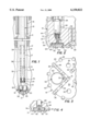
- FIG. 2 is a detail section view of a typical diamond bit having a microwave energy sensor disposed therein and taken in the plane of the axis of rotation of the bit;
- FIG. 3 is a partial plan view of the bit shown in FIG. 2;
- FIG. 4 is a detail view in the same plane as that of FIG. 2 of an alternate embodiment of a sensor mounted in a diamond type bit in accordance with the invention.
- FIG. 1 there is shown a portion of a wellbore 10 being formed in an earth formation 12 which may have several relatively thin vertically spaced layers or beds, not shown, which are desired to be measured to determine if hydrocarbon fluids are present in commercial quantities.
- the wellbore 10 is shown being formed by a rotatable drill stem 14 extending through a cased portion of the wellbore 10 defined by a conventional casing 16.
- the drill stem 14 includes two instrument carrying sections or subs, 17 and 19 connected thereto and a distal end characterized by a drill bit 18 which, preferably, is of the so called diamond type or PDC type, aforementioned.
- This type of bit is characterized by a generally cylindrical body 20, see FIGS.
- the bit body 20 is provided with a generally transverse end face 30 portion which intersects a sloping outer sidewall 31, preferably having a parabolic shape in the plane of FIG. 2 so as to minimize the formation area ahead of the bit which would accumulate drilling fluid filtrate.
- Plural drilling fluid ejection ports or nozzles 32 and 33 are operable to be in communication with a passage 34 which receives drilling fluid through the drill stem 14 in a conventional manner.
- the bit 18 also has conventional circumferentially spaced blades 36, 38, 40 and 42, FIGS. 2 and 3, on which polycrystalline diamond blanks or inserts 44 are disposed, respectively.
- Conventional gage inserts 45 are also provided on the body 20.
- the bit 18 is exemplary and those skilled in the art will recognize that other specific bit designs of the so called diamond type, or the like, may be used in conjunction with the present invention.
- the bit 18 is adapted to include a sensor, generally designated by the numeral 50, disposed in the body 20 and opening toward the transverse end face 30. At least one nozzle (FIG. 3) 33 is directed to cause fresh drilling fluid to wash across the sensor 50 to maintain a predetermined thin layer of drilling fluid between the sensor and the uninvaded formation ahead of the bit 18.
- the sensor 50 is operable to transmit microwave frequency range electromagnetic wave energy into the formation 12 directly ahead of the bit, in particular, into the formation zone 13.
- the sensor 50 is in communication with a conventional source of microwave frequency range electromagnetic wave energy and which comprises not only a source but a receiver of reflected energy from the sensor 50. This source is generally designated by the numeral 52 in FIG. 1 and is suitably disposed in the sub 19.
- the sub 17 is adapted to include certain formation measuring tools or devices such as a formation density logging instrument 54 and a formation porosity measuring instrument 56, both disposed in the sub.
- the density measuring device or instrument 54 may be of a type known as a gamma-gamma density sensor comprising multiple sets of detector banks, not shown, which are comprised of rugged Geiger-Mueller (GM) tubes placed around the circumference of a sensor insert, also not shown, in a common plane perpendicular to the axis of the instrument. These detectors are of the same axial distance from a gamma radiation source.
- GM Geiger-Mueller
- the porosity sensing instrument 56 may be of a type commercially available and known as a neutron type sensor or compensated neutron sensor such as developed as a commercial service by Schlumberger, Houston, Tex. Measurements carried out by the instruments 54 and 56 may be compared to determine the actual porosity and or lithology of the formation material being penetrated by the wellbore 10.
- the sensor 50 may be characterized as a microwave frequency range antenna for emitting electromagnetic radiation in a frequency range of about 0.10 GHz to 3.0 GHz.
- the sensor 50 as illustrated, is characterized by a ceramic disc 60 having a conductive metallic backing 62 which is isolated from the bit body 20 by a suitable dielectric material 64.
- a conductor pin 66 extends from the metallic backing 62 into a connector 68.
- the connector 68 has a coaxial sleeve conductor 70 formed thereon which is insulated from a body member 72 which is in conductive engagement with the bit body 20.
- FIG. 4 shows an alternate embodiment of a sensor in accordance with the invention and generally designated by the numeral 80.
- the sensor 80 is adapted to be mounted in the bit body 20, with some modification thereto, in place of the sensor 50 and is comprised of a center conductor 82 which is isolated from an outer conductor 84 by a suitable dielectric sleeve portion 86.
- the sensor 80 may be characterized as a microwave energy wave guide for emitting microwave energy into the formation zone 13, which is essentially contiguous with the bit end face 30.
- the sensor 50 may function as a microwave energy antenna which also emits microwave energy into the formation zone 13. Both sensors 50 and 80 are suitably connected to cable means 90, FIG. 1, connected to the instrument 52.
- the instrument 52 may be characterized as a so called network analyzer which is adapted to generate microwave frequency range electromagnetic wave energy for transmission through the antenna or sensor 50 or the wave guide sensor 80 via the aforementioned cable 90. This microwave energy is emitted into the formation zone 13 and reflected back to the sensors 50 or 80 with an altered amplitude and phase angle, for example.
- the so called reflection co-efficient which is a function of the complex impedance of the formation material in the zone 13 may be related to the dielectric properties of the material which, in turn, can be related to the water content of the material. Calibration of the sensors 50 and 80 may be required to compensate for a thin layer of wellbore fluid between the bit face 30 and the formation zone 13.
- This thin layer of fluid will typically exist during operation of the bit since the blades 36 and the inserts 44 axially project from the face 30. A very small amount of wellbore fluid may be considered to invade the formation zone 13 although not to the extent which will render inaccurate the measurements made by the instrument 52.
- the reflected microwave energy signal sensed by the sensors 50 and 80 may be stored in a suitable storage medium and analyzed later or the sub 19 may include an onboard digital computer, not shown, operably connected to the network analyzer 52 for producing real time values of the dielectric constant of the material of the formation. zone 13.
- the instrument 52 may be a device commercially available such as a network analyzer of the 8700 Series manufactured by Hewlett Packard Company of Rockville, Md.
- the measurement of dielectric properties of the material in the formation zone 13 may be correlated with porosity measurements obtained by the instruments 54, 56 since the dielectric property measurements will indicate the water content of the formation zone 13. Measurement of density and porosity obtained by the instruments 54, 56, will, of course, not be obtained until these instruments pass through the zone 13 with continued drilling by the drill stem 14 and bit 18. In any event upon retrieval of the drill stem 14 the information accumulated by the instruments 52, 54 and 56 may be analyzed to determine if the pore volume of the earth formation zone 13 is entirely occupied by water or, absent that indication, it may be assumed that quantities of hydrocarbon fluids may be present in the pore spaces of the formation material.
- the sensors 50 or 80 in the bit 18 and disposed in proximity to the bit face 30 and the previously undisturbed formation of the zone 13 material Thanks to the provision of the sensors 50 or 80 in the bit 18 and disposed in proximity to the bit face 30 and the previously undisturbed formation of the zone 13 material, a more accurate measurement of the formation material properties, such as water content, may be obtained since this material is not substantially invaded by wellbore fluids before measurements can be taken. Furthermore, as mentioned hereinabove, microwave energy alteration measurements are particularly useful for evaluating relatively thin layers of formation material because of their relatively high spatial resolution capability. Providing the sensors 50 or 80 in the bit face 30 thus offers the ability to detect the presence of hydrocarbon fluids in relatively thin layers of subterranean earth formations.
- drilling fluid filtrate invasion into the earth formation directly ahead of the bit end face is reduced.
- a drilling fluid ejection nozzle such as the nozzle 33 arranged to provide a constant, uniform flow of drilling fluid across the face of the sensors 50 or 80, provides a consistent, thin layer of drilling fluid which may be taken into account when observing the readings of energy reflected back to the sensor or emitted from the sensor, which is consistent and does not interfere with an accurate determination of the formation properties ahead of the bit.
- the operation of the drill stem 14, including the arrangement illustrated in FIG. 1, is believed to be understandable from the foregoing description.
- the drill stem 14 and bit 18 are rotated about central axis 15, FIG. 1, and continuous measurements of the dielectric properties of the formation zone 13 may be carried out if the instrument 52 is operable with the sensors 50 or 80 to emit microwave frequency range electromagnetic radiation and sense the energy loss or reflection so that at least one of the reflection coefficient, including the dielectric loss factor or loss tangent can be determined.
- the measurements carried out by the instruments 52, 54 and 56 may be suitably stored for later retrieval and analysis upon withdrawal of the drill stem 14 from the wellbore or, if space permits, on board analysis of the measurements may be obtained and transmitted through the drill stem by suitable signal transmitting means, such as stress wave telemetry or so called wireline telemetry, for example.
Abstract
Description
Claims (6)
Priority Applications (1)
| Application Number | Priority Date | Filing Date | Title |
|---|---|---|---|
| US08/448,134 US6150822A (en) | 1994-01-21 | 1995-07-17 | Sensor in bit for measuring formation properties while drilling |
Applications Claiming Priority (2)
| Application Number | Priority Date | Filing Date | Title |
|---|---|---|---|
| US08/184,795 US5475309A (en) | 1994-01-21 | 1994-01-21 | Sensor in bit for measuring formation properties while drilling including a drilling fluid ejection nozzle for ejecting a uniform layer of fluid over the sensor |
| US08/448,134 US6150822A (en) | 1994-01-21 | 1995-07-17 | Sensor in bit for measuring formation properties while drilling |
Related Parent Applications (1)
| Application Number | Title | Priority Date | Filing Date |
|---|---|---|---|
| US08/184,795 Continuation US5475309A (en) | 1994-01-21 | 1994-01-21 | Sensor in bit for measuring formation properties while drilling including a drilling fluid ejection nozzle for ejecting a uniform layer of fluid over the sensor |
Publications (1)
| Publication Number | Publication Date |
|---|---|
| US6150822A true US6150822A (en) | 2000-11-21 |
Family
ID=22678364
Family Applications (2)
| Application Number | Title | Priority Date | Filing Date |
|---|---|---|---|
| US08/184,795 Expired - Lifetime US5475309A (en) | 1994-01-21 | 1994-01-21 | Sensor in bit for measuring formation properties while drilling including a drilling fluid ejection nozzle for ejecting a uniform layer of fluid over the sensor |
| US08/448,134 Expired - Lifetime US6150822A (en) | 1994-01-21 | 1995-07-17 | Sensor in bit for measuring formation properties while drilling |
Family Applications Before (1)
| Application Number | Title | Priority Date | Filing Date |
|---|---|---|---|
| US08/184,795 Expired - Lifetime US5475309A (en) | 1994-01-21 | 1994-01-21 | Sensor in bit for measuring formation properties while drilling including a drilling fluid ejection nozzle for ejecting a uniform layer of fluid over the sensor |
Country Status (1)
| Country | Link |
|---|---|
| US (2) | US5475309A (en) |
Cited By (95)
| Publication number | Priority date | Publication date | Assignee | Title |
|---|---|---|---|---|
| US6367564B1 (en) * | 1999-09-24 | 2002-04-09 | Vermeer Manufacturing Company | Apparatus and method for providing electrical transmission of power and signals in a directional drilling apparatus |
| US20020149499A1 (en) * | 1999-02-19 | 2002-10-17 | Dresser Industries, Inc. | Casing mounted sensors, actuators and generators |
| US6467341B1 (en) | 2001-04-24 | 2002-10-22 | Schlumberger Technology Corporation | Accelerometer caliper while drilling |
| US20050132794A1 (en) * | 2003-12-22 | 2005-06-23 | Spross Ronald L. | System, method and apparatus for petrophysical and geophysical measurements at the drilling bit |
| US20070114062A1 (en) * | 2005-11-21 | 2007-05-24 | Hall David R | Drill Bit Assembly with a Logging Device |
| US20070229304A1 (en) * | 2006-03-23 | 2007-10-04 | Hall David R | Drill Bit with an Electrically Isolated Transmitter |
| WO2007130749A2 (en) | 2006-03-24 | 2007-11-15 | Hall David R | Drill bit assembly with a logging device |
| US20080035388A1 (en) * | 2006-08-11 | 2008-02-14 | Hall David R | Drill Bit Nozzle |
| US20080079432A1 (en) * | 2006-09-28 | 2008-04-03 | Baker Hughes Incorporated | Broadband resistivity interpretation |
| US20080079433A1 (en) * | 2006-09-28 | 2008-04-03 | Baker Hughes Incorporated | Broadband Resistivity Interpretation |
| US7392857B1 (en) | 2007-01-03 | 2008-07-01 | Hall David R | Apparatus and method for vibrating a drill bit |
| US7419018B2 (en) | 2006-11-01 | 2008-09-02 | Hall David R | Cam assembly in a downhole component |
| US7419016B2 (en) | 2006-03-23 | 2008-09-02 | Hall David R | Bi-center drill bit |
| US7424922B2 (en) | 2005-11-21 | 2008-09-16 | Hall David R | Rotary valve for a jack hammer |
| US7484576B2 (en) | 2006-03-23 | 2009-02-03 | Hall David R | Jack element in communication with an electric motor and or generator |
| US7497279B2 (en) | 2005-11-21 | 2009-03-03 | Hall David R | Jack element adapted to rotate independent of a drill bit |
| US7527110B2 (en) | 2006-10-13 | 2009-05-05 | Hall David R | Percussive drill bit |
| US7533737B2 (en) | 2005-11-21 | 2009-05-19 | Hall David R | Jet arrangement for a downhole drill bit |
| US7559379B2 (en) | 2005-11-21 | 2009-07-14 | Hall David R | Downhole steering |
| US7571780B2 (en) | 2006-03-24 | 2009-08-11 | Hall David R | Jack element for a drill bit |
| US7591327B2 (en) | 2005-11-21 | 2009-09-22 | Hall David R | Drilling at a resonant frequency |
| US7600586B2 (en) | 2006-12-15 | 2009-10-13 | Hall David R | System for steering a drill string |
| US7617886B2 (en) | 2005-11-21 | 2009-11-17 | Hall David R | Fluid-actuated hammer bit |
| US20090321132A1 (en) * | 2006-07-28 | 2009-12-31 | Mcgill University | Electromagnetic energy assisted drilling system and method |
| US7641002B2 (en) | 2005-11-21 | 2010-01-05 | Hall David R | Drill bit |
| DE102008026456A1 (en) * | 2008-06-03 | 2010-01-07 | Tracto-Technik Gmbh & Co. Kg | wellhead |
| US20100032210A1 (en) * | 2005-06-07 | 2010-02-11 | Baker Hughes Incorporated | Monitoring Drilling Performance in a Sub-Based Unit |
| US7661487B2 (en) | 2006-03-23 | 2010-02-16 | Hall David R | Downhole percussive tool with alternating pressure differentials |
| US20100038136A1 (en) * | 2008-08-18 | 2010-02-18 | Baker Hughes Incorporated | Drill Bit With A Sensor For Estimating Rate Of Penetration And Apparatus For Using Same |
| US20100051292A1 (en) * | 2008-08-26 | 2010-03-04 | Baker Hughes Incorporated | Drill Bit With Weight And Torque Sensors |
| US7694756B2 (en) | 2006-03-23 | 2010-04-13 | Hall David R | Indenting member for a drill bit |
| US20100089645A1 (en) * | 2008-10-13 | 2010-04-15 | Baker Hughes Incorporated | Bit Based Formation Evaluation Using A Gamma Ray Sensor |
| US20100118657A1 (en) * | 2008-11-10 | 2010-05-13 | Baker Hughes Incorporated | Bit Based Formation Evaluation and Drill Bit and Drill String Analysis Using an Acoustic Sensor |
| US20100123462A1 (en) * | 1999-01-28 | 2010-05-20 | Halliburton Energy Services, Inc. | Electromagnetic Wave Resistivity Tool Having a Tilted Antenna for Geosteering within a Desired Payzone |
| US7721826B2 (en) | 2007-09-06 | 2010-05-25 | Schlumberger Technology Corporation | Downhole jack assembly sensor |
| USD620510S1 (en) | 2006-03-23 | 2010-07-27 | Schlumberger Technology Corporation | Drill bit |
| US7762353B2 (en) | 2006-03-23 | 2010-07-27 | Schlumberger Technology Corporation | Downhole valve mechanism |
| US20100307835A1 (en) * | 2009-06-09 | 2010-12-09 | Baker Hughes Incorporated | Drill Bit with Weight and Torque Sensors |
| US20100319992A1 (en) * | 2009-06-19 | 2010-12-23 | Baker Hughes Incorporated | Apparatus and Method for Determining Corrected Weight-On-Bit |
| US7866416B2 (en) | 2007-06-04 | 2011-01-11 | Schlumberger Technology Corporation | Clutch for a jack element |
| US7900720B2 (en) | 2006-01-18 | 2011-03-08 | Schlumberger Technology Corporation | Downhole drive shaft connection |
| US20110060527A1 (en) * | 2009-09-10 | 2011-03-10 | Baker Hughes Incorporated | Drill Bit with Rate of Penetration Sensor |
| US7954401B2 (en) | 2006-10-27 | 2011-06-07 | Schlumberger Technology Corporation | Method of assembling a drill bit with a jack element |
| US7967083B2 (en) | 2007-09-06 | 2011-06-28 | Schlumberger Technology Corporation | Sensor for determining a position of a jack element |
| US8011457B2 (en) | 2006-03-23 | 2011-09-06 | Schlumberger Technology Corporation | Downhole hammer assembly |
| US8020471B2 (en) | 2005-11-21 | 2011-09-20 | Schlumberger Technology Corporation | Method for manufacturing a drill bit |
| WO2011133544A3 (en) * | 2010-04-19 | 2011-12-15 | Baker Hughes Incorporated | Apparatus and methods for estimating tool inclination using bit-based gamma ray sensors |
| US8085050B2 (en) | 2007-03-16 | 2011-12-27 | Halliburton Energy Services, Inc. | Robust inversion systems and methods for azimuthally sensitive resistivity logging tools |
| WO2011133530A3 (en) * | 2010-04-19 | 2011-12-29 | Baker Hughes Incorporated | Formation evaluation using a bit-based active radiation source and a gamma ray detector |
| US8122980B2 (en) | 2007-06-22 | 2012-02-28 | Schlumberger Technology Corporation | Rotary drag bit with pointed cutting elements |
| US8191651B2 (en) | 2006-08-11 | 2012-06-05 | Hall David R | Sensor on a formation engaging member of a drill bit |
| US8205688B2 (en) | 2005-11-21 | 2012-06-26 | Hall David R | Lead the bit rotary steerable system |
| US8215420B2 (en) | 2006-08-11 | 2012-07-10 | Schlumberger Technology Corporation | Thermally stable pointed diamond with increased impact resistance |
| US8225883B2 (en) | 2005-11-21 | 2012-07-24 | Schlumberger Technology Corporation | Downhole percussive tool with alternating pressure differentials |
| US8240404B2 (en) | 2006-08-11 | 2012-08-14 | Hall David R | Roof bolt bit |
| US8267196B2 (en) | 2005-11-21 | 2012-09-18 | Schlumberger Technology Corporation | Flow guide actuation |
| US8297375B2 (en) | 2005-11-21 | 2012-10-30 | Schlumberger Technology Corporation | Downhole turbine |
| US8297378B2 (en) | 2005-11-21 | 2012-10-30 | Schlumberger Technology Corporation | Turbine driven hammer that oscillates at a constant frequency |
| US8316964B2 (en) * | 2006-03-23 | 2012-11-27 | Schlumberger Technology Corporation | Drill bit transducer device |
| US20120312599A1 (en) * | 2011-06-13 | 2012-12-13 | Baker Hughes Incorporated | Cutting elements comprising sensors, earth-boring tools having such sensors, and associated methods |
| US8333254B2 (en) | 2010-10-01 | 2012-12-18 | Hall David R | Steering mechanism with a ring disposed about an outer diameter of a drill bit and method for drilling |
| US8342266B2 (en) | 2011-03-15 | 2013-01-01 | Hall David R | Timed steering nozzle on a downhole drill bit |
| USD674422S1 (en) | 2007-02-12 | 2013-01-15 | Hall David R | Drill bit with a pointed cutting element and a shearing cutting element |
| US20130020479A1 (en) * | 2011-07-19 | 2013-01-24 | Baker Hughes Incorporated | Apparatus and Method for Determining Formation Density from Nuclear Density Measurements Made Using Sensors at More Than One Location |
| US8360174B2 (en) | 2006-03-23 | 2013-01-29 | Schlumberger Technology Corporation | Lead the bit rotary steerable tool |
| USD678368S1 (en) | 2007-02-12 | 2013-03-19 | David R. Hall | Drill bit with a pointed cutting element |
| US8418784B2 (en) | 2010-05-11 | 2013-04-16 | David R. Hall | Central cutting region of a drilling head assembly |
| US8434573B2 (en) | 2006-08-11 | 2013-05-07 | Schlumberger Technology Corporation | Degradation assembly |
| US8522897B2 (en) | 2005-11-21 | 2013-09-03 | Schlumberger Technology Corporation | Lead the bit rotary steerable tool |
| US8528664B2 (en) | 2005-11-21 | 2013-09-10 | Schlumberger Technology Corporation | Downhole mechanism |
| US8540037B2 (en) | 2008-04-30 | 2013-09-24 | Schlumberger Technology Corporation | Layered polycrystalline diamond |
| US8550190B2 (en) | 2010-04-01 | 2013-10-08 | David R. Hall | Inner bit disposed within an outer bit |
| US8567532B2 (en) | 2006-08-11 | 2013-10-29 | Schlumberger Technology Corporation | Cutting element attached to downhole fixed bladed bit at a positive rake angle |
| US8573331B2 (en) | 2006-08-11 | 2013-11-05 | David R. Hall | Roof mining drill bit |
| US8581592B2 (en) | 2008-12-16 | 2013-11-12 | Halliburton Energy Services, Inc. | Downhole methods and assemblies employing an at-bit antenna |
| US8590644B2 (en) | 2006-08-11 | 2013-11-26 | Schlumberger Technology Corporation | Downhole drill bit |
| US8616305B2 (en) | 2006-08-11 | 2013-12-31 | Schlumberger Technology Corporation | Fixed bladed bit that shifts weight between an indenter and cutting elements |
| US8622155B2 (en) | 2006-08-11 | 2014-01-07 | Schlumberger Technology Corporation | Pointed diamond working ends on a shear bit |
| US8701799B2 (en) | 2009-04-29 | 2014-04-22 | Schlumberger Technology Corporation | Drill bit cutter pocket restitution |
| US8714285B2 (en) | 2006-08-11 | 2014-05-06 | Schlumberger Technology Corporation | Method for drilling with a fixed bladed bit |
| US8820440B2 (en) | 2010-10-01 | 2014-09-02 | David R. Hall | Drill bit steering assembly |
| US8839888B2 (en) | 2010-04-23 | 2014-09-23 | Schlumberger Technology Corporation | Tracking shearing cutters on a fixed bladed drill bit with pointed cutting elements |
| US8950517B2 (en) | 2005-11-21 | 2015-02-10 | Schlumberger Technology Corporation | Drill bit with a retained jack element |
| US9051795B2 (en) | 2006-08-11 | 2015-06-09 | Schlumberger Technology Corporation | Downhole drill bit |
| US9068410B2 (en) | 2006-10-26 | 2015-06-30 | Schlumberger Technology Corporation | Dense diamond body |
| US9157315B2 (en) | 2006-12-15 | 2015-10-13 | Halliburton Energy Services, Inc. | Antenna coupling component measurement tool having a rotating antenna configuration |
| US9222350B2 (en) | 2011-06-21 | 2015-12-29 | Diamond Innovations, Inc. | Cutter tool insert having sensing device |
| US9316061B2 (en) | 2006-08-11 | 2016-04-19 | David R. Hall | High impact resistant degradation element |
| US9366089B2 (en) | 2006-08-11 | 2016-06-14 | Schlumberger Technology Corporation | Cutting element attached to downhole fixed bladed bit at a positive rake angle |
| US9465132B2 (en) | 1999-01-28 | 2016-10-11 | Halliburton Energy Services, Inc. | Tool for azimuthal resistivity measurement and bed boundary detection |
| GB2543356A (en) * | 2015-10-16 | 2017-04-19 | Reeves Wireline Tech Ltd | Apparatuses and methods for determining permittivity in downhole locations |
| US9851467B2 (en) | 2006-08-08 | 2017-12-26 | Halliburton Energy Services, Inc. | Tool for azimuthal resistivity measurement and bed boundary detection |
| US9915102B2 (en) | 2006-08-11 | 2018-03-13 | Schlumberger Technology Corporation | Pointed working ends on a bit |
| US10029391B2 (en) | 2006-10-26 | 2018-07-24 | Schlumberger Technology Corporation | High impact resistant tool with an apex width between a first and second transitions |
| US10119388B2 (en) | 2006-07-11 | 2018-11-06 | Halliburton Energy Services, Inc. | Modular geosteering tool assembly |
Families Citing this family (27)
| Publication number | Priority date | Publication date | Assignee | Title |
|---|---|---|---|---|
| DE69635694T2 (en) * | 1995-02-16 | 2006-09-14 | Baker-Hughes Inc., Houston | Method and device for detecting and recording the conditions of use of a drill bit during drilling |
| US6571886B1 (en) | 1995-02-16 | 2003-06-03 | Baker Hughes Incorporated | Method and apparatus for monitoring and recording of the operating condition of a downhole drill bit during drilling operations |
| US6230822B1 (en) * | 1995-02-16 | 2001-05-15 | Baker Hughes Incorporated | Method and apparatus for monitoring and recording of the operating condition of a downhole drill bit during drilling operations |
| US5720354A (en) * | 1996-01-11 | 1998-02-24 | Vermeer Manufacturing Company | Trenchless underground boring system with boring tool location |
| US6269892B1 (en) * | 1998-12-21 | 2001-08-07 | Dresser Industries, Inc. | Steerable drilling system and method |
| DE10116363B4 (en) * | 2001-04-02 | 2006-03-16 | Tracto-Technik Gmbh | Drilling head of a drilling device, in particular Spülbohrkopf a flat drilling |
| EP1256692A1 (en) * | 2001-05-08 | 2002-11-13 | Massimo Sacchetto | Drilling method and means for a direct survey of geotechnical parameters |
| US6814162B2 (en) * | 2002-08-09 | 2004-11-09 | Smith International, Inc. | One cone bit with interchangeable cutting structures, a box-end connection, and integral sensory devices |
| EP1662274A1 (en) * | 2004-11-24 | 2006-05-31 | Services Petroliers Schlumberger | A probe for measuring the electromagnetic properties of a down-hole material |
| US20090032304A1 (en) * | 2007-08-03 | 2009-02-05 | Ohmart/Vega Corporation | Mud level sensing system |
| US8269509B2 (en) * | 2008-11-17 | 2012-09-18 | General Electric Company | System and method for measuring thickness of a refractory wall of a gasifier using electromagnetic energy |
| GB2476653A (en) * | 2009-12-30 | 2011-07-06 | Wajid Rasheed | Tool and Method for Look-Ahead Formation Evaluation in advance of the drill-bit |
| US9297251B2 (en) * | 2013-02-20 | 2016-03-29 | Schlumberger Technology Corporation | Drill bit systems with temperature sensors and applications using temperature sensor measurements |
| US10145178B2 (en) | 2013-05-22 | 2018-12-04 | Halliburton Energy Services, Inc. | Roller cone seal failure detection using an integrated computational element |
| SG11201601744QA (en) | 2013-12-19 | 2016-04-28 | Halliburton Energy Services Inc | Self-assembling packer |
| NO347228B1 (en) | 2013-12-19 | 2023-07-17 | Halliburton Energy Services Inc | Intervention Tool for Delivering Self-Assembling Repair Fluid |
| US9797222B2 (en) | 2013-12-30 | 2017-10-24 | Halliburton Energy Services, Inc. | Ferrofluid tool for enhancing magnetic fields in a wellbore |
| US9896910B2 (en) | 2013-12-30 | 2018-02-20 | Halliburton Energy Services, Inc. | Ferrofluid tool for isolation of objects in a wellbore |
| MX2016006840A (en) | 2013-12-30 | 2016-12-16 | Halliburton Energy Services Inc | Ferrofluid tool for providing modifiable structures in boreholes. |
| EP3039238A1 (en) | 2013-12-30 | 2016-07-06 | Halliburton Energy Services, Inc. | Ferrofluid tool for influencing electrically conductive paths in a wellbore |
| MX2017005458A (en) | 2014-12-31 | 2017-07-04 | Halliburton Energy Services Inc | Visualization of look-ahead sensor data for wellbore drilling tools. |
| CN104863576B (en) * | 2015-04-03 | 2017-12-08 | 山东大学 | Judge that rig is crept into the method for geological stratification residing for drill bit during certain depth |
| CN104793264B (en) * | 2015-04-03 | 2017-12-08 | 山东大学 | Geological state applied to rig reflects and forward probe system and method in real time |
| WO2017003443A1 (en) | 2015-06-30 | 2017-01-05 | Halliburton Energy Services, Inc. | Outflow control device for creating a packer |
| CN105909233B (en) * | 2016-04-29 | 2019-01-25 | 中国石油大学(北京) | The method and device of distance measuring signal between a kind of extraction well |
| CN107398582B (en) * | 2017-06-12 | 2019-06-28 | 宁波工程学院 | Wall detection electric drill and detection method based on mechanical parameter characteristic |
| CN113530523A (en) * | 2021-07-12 | 2021-10-22 | 华北科技学院(中国煤矿安全技术培训中心) | Coal bed gas drilling while drilling instrument |
Citations (7)
| Publication number | Priority date | Publication date | Assignee | Title |
|---|---|---|---|---|
| US2310611A (en) * | 1938-12-23 | 1943-02-09 | Geophysical Res Corp | Electrical exploration of geological strata |
| US2354887A (en) * | 1942-10-29 | 1944-08-01 | Stanolind Oil & Gas Co | Well signaling system |
| US2917704A (en) * | 1954-05-24 | 1959-12-15 | Jan J Arps | Earth formation logging system |
| US3293542A (en) * | 1963-03-18 | 1966-12-20 | Phillips Petroleum Co | Electrical well logging apparatus including a drill collar having spaced electrodes mounted thereon for making resistivity measurements while drilling |
| US3412321A (en) * | 1966-11-14 | 1968-11-19 | Chevron Res | Oil-water contact location with frequency modulated electromagnetic energy |
| US4893084A (en) * | 1988-05-19 | 1990-01-09 | Halliburton Logging Services, Inc. | Formation electromagnetic parameters measuring tool using transmitter reference and reflected signals and a received signal |
| US4940943A (en) * | 1988-04-19 | 1990-07-10 | Baroid Technology, Inc. | Method and apparatus for optimizing the reception pattern of the antenna of a propagating electromagnetic wave logging tool |
Family Cites Families (5)
| Publication number | Priority date | Publication date | Assignee | Title |
|---|---|---|---|---|
| US2316611A (en) * | 1938-09-27 | 1943-04-13 | Neuse Wilhelm | Expansion thermometer |
| US3412815A (en) * | 1966-11-14 | 1968-11-26 | Chevron Res | Electromagnetic radiation method for guiding the drilling of oil wells after the borehole has entered a massive earth formation of chemically deposited material, by a mistake, accident, or the like |
| US4884071A (en) * | 1987-01-08 | 1989-11-28 | Hughes Tool Company | Wellbore tool with hall effect coupling |
| US4933690A (en) * | 1988-10-31 | 1990-06-12 | Eastman Kodak | Slide changing apparatus with slide jam protection |
| US5325714A (en) * | 1993-05-12 | 1994-07-05 | Baker Hughes Incorporated | Steerable motor system with integrated formation evaluation logging capacity |
-
1994
- 1994-01-21 US US08/184,795 patent/US5475309A/en not_active Expired - Lifetime
-
1995
- 1995-07-17 US US08/448,134 patent/US6150822A/en not_active Expired - Lifetime
Patent Citations (7)
| Publication number | Priority date | Publication date | Assignee | Title |
|---|---|---|---|---|
| US2310611A (en) * | 1938-12-23 | 1943-02-09 | Geophysical Res Corp | Electrical exploration of geological strata |
| US2354887A (en) * | 1942-10-29 | 1944-08-01 | Stanolind Oil & Gas Co | Well signaling system |
| US2917704A (en) * | 1954-05-24 | 1959-12-15 | Jan J Arps | Earth formation logging system |
| US3293542A (en) * | 1963-03-18 | 1966-12-20 | Phillips Petroleum Co | Electrical well logging apparatus including a drill collar having spaced electrodes mounted thereon for making resistivity measurements while drilling |
| US3412321A (en) * | 1966-11-14 | 1968-11-19 | Chevron Res | Oil-water contact location with frequency modulated electromagnetic energy |
| US4940943A (en) * | 1988-04-19 | 1990-07-10 | Baroid Technology, Inc. | Method and apparatus for optimizing the reception pattern of the antenna of a propagating electromagnetic wave logging tool |
| US4893084A (en) * | 1988-05-19 | 1990-01-09 | Halliburton Logging Services, Inc. | Formation electromagnetic parameters measuring tool using transmitter reference and reflected signals and a received signal |
Cited By (145)
| Publication number | Priority date | Publication date | Assignee | Title |
|---|---|---|---|---|
| US8085049B2 (en) | 1999-01-28 | 2011-12-27 | Halliburton Energy Services, Inc. | Electromagnetic wave resistivity tool having a tilted antenna for geosteering within a desired payzone |
| US20100123462A1 (en) * | 1999-01-28 | 2010-05-20 | Halliburton Energy Services, Inc. | Electromagnetic Wave Resistivity Tool Having a Tilted Antenna for Geosteering within a Desired Payzone |
| US9465132B2 (en) | 1999-01-28 | 2016-10-11 | Halliburton Energy Services, Inc. | Tool for azimuthal resistivity measurement and bed boundary detection |
| US7046165B2 (en) * | 1999-02-19 | 2006-05-16 | Halliburton Energy Services, Inc. | Method for collecting geological data ahead of a drill bit |
| US20020154027A1 (en) * | 1999-02-19 | 2002-10-24 | Dresser Industries, Inc. | Casing mounted sensors, actuators and generators |
| US7932834B2 (en) | 1999-02-19 | 2011-04-26 | Halliburton Energy Services. Inc. | Data relay system for instrument and controller attached to a drill string |
| US20070139217A1 (en) * | 1999-02-19 | 2007-06-21 | Halliburton Energy Services, Inc., A Delaware Corp | Data relay system for casing mounted sensors, actuators and generators |
| US7173542B2 (en) | 1999-02-19 | 2007-02-06 | Halliburton Energy Services, Inc. | Data relay for casing mounted sensors, actuators and generators |
| US20020149499A1 (en) * | 1999-02-19 | 2002-10-17 | Dresser Industries, Inc. | Casing mounted sensors, actuators and generators |
| US20070132605A1 (en) * | 1999-02-19 | 2007-06-14 | Halliburton Energy Services, Inc., A Delaware Corporation | Casing mounted sensors, actuators and generators |
| USRE39259E1 (en) * | 1999-09-24 | 2006-09-05 | Vermeer Manufacturing Company | Apparatus and method for providing electrical transmission of power and signals in a directional drilling apparatus |
| US6367564B1 (en) * | 1999-09-24 | 2002-04-09 | Vermeer Manufacturing Company | Apparatus and method for providing electrical transmission of power and signals in a directional drilling apparatus |
| US6467341B1 (en) | 2001-04-24 | 2002-10-22 | Schlumberger Technology Corporation | Accelerometer caliper while drilling |
| US7207215B2 (en) * | 2003-12-22 | 2007-04-24 | Halliburton Energy Services, Inc. | System, method and apparatus for petrophysical and geophysical measurements at the drilling bit |
| US20070186639A1 (en) * | 2003-12-22 | 2007-08-16 | Spross Ronald L | System, method and apparatus for petrophysical and geophysical measurements at the drilling bit |
| US7743654B2 (en) * | 2003-12-22 | 2010-06-29 | Halliburton Energy Services, Inc. | System, method and apparatus for petrophysical and geophysical measurements at the drilling bit |
| EP1709280A2 (en) * | 2003-12-22 | 2006-10-11 | Halliburton Energy Services, Inc. | System, method and apparatus for petrophysical and geophysical measurements at the drilling bit |
| WO2005062830A2 (en) | 2003-12-22 | 2005-07-14 | Halliburton Energy Services, Inc. | System, method and apparatus for petrophysical and geophysical measurements at the drilling bit |
| EP1709280A4 (en) * | 2003-12-22 | 2011-09-28 | Halliburton Energy Serv Inc | System, method and apparatus for petrophysical and geophysical measurements at the drilling bit |
| US20050132794A1 (en) * | 2003-12-22 | 2005-06-23 | Spross Ronald L. | System, method and apparatus for petrophysical and geophysical measurements at the drilling bit |
| WO2005062830A3 (en) * | 2003-12-22 | 2009-04-02 | Halliburton Energy Serv Inc | System, method and apparatus for petrophysical and geophysical measurements at the drilling bit |
| US8376065B2 (en) | 2005-06-07 | 2013-02-19 | Baker Hughes Incorporated | Monitoring drilling performance in a sub-based unit |
| US20100032210A1 (en) * | 2005-06-07 | 2010-02-11 | Baker Hughes Incorporated | Monitoring Drilling Performance in a Sub-Based Unit |
| US20070114062A1 (en) * | 2005-11-21 | 2007-05-24 | Hall David R | Drill Bit Assembly with a Logging Device |
| US8281882B2 (en) | 2005-11-21 | 2012-10-09 | Schlumberger Technology Corporation | Jack element for a drill bit |
| US7424922B2 (en) | 2005-11-21 | 2008-09-16 | Hall David R | Rotary valve for a jack hammer |
| US8205688B2 (en) | 2005-11-21 | 2012-06-26 | Hall David R | Lead the bit rotary steerable system |
| US8225883B2 (en) | 2005-11-21 | 2012-07-24 | Schlumberger Technology Corporation | Downhole percussive tool with alternating pressure differentials |
| US7497279B2 (en) | 2005-11-21 | 2009-03-03 | Hall David R | Jack element adapted to rotate independent of a drill bit |
| US7398837B2 (en) * | 2005-11-21 | 2008-07-15 | Hall David R | Drill bit assembly with a logging device |
| US8950517B2 (en) | 2005-11-21 | 2015-02-10 | Schlumberger Technology Corporation | Drill bit with a retained jack element |
| US7533737B2 (en) | 2005-11-21 | 2009-05-19 | Hall David R | Jet arrangement for a downhole drill bit |
| US7559379B2 (en) | 2005-11-21 | 2009-07-14 | Hall David R | Downhole steering |
| US8267196B2 (en) | 2005-11-21 | 2012-09-18 | Schlumberger Technology Corporation | Flow guide actuation |
| US8408336B2 (en) | 2005-11-21 | 2013-04-02 | Schlumberger Technology Corporation | Flow guide actuation |
| US7591327B2 (en) | 2005-11-21 | 2009-09-22 | Hall David R | Drilling at a resonant frequency |
| US8020471B2 (en) | 2005-11-21 | 2011-09-20 | Schlumberger Technology Corporation | Method for manufacturing a drill bit |
| US7617886B2 (en) | 2005-11-21 | 2009-11-17 | Hall David R | Fluid-actuated hammer bit |
| US7967082B2 (en) | 2005-11-21 | 2011-06-28 | Schlumberger Technology Corporation | Downhole mechanism |
| US7641002B2 (en) | 2005-11-21 | 2010-01-05 | Hall David R | Drill bit |
| US8297375B2 (en) | 2005-11-21 | 2012-10-30 | Schlumberger Technology Corporation | Downhole turbine |
| US8522897B2 (en) | 2005-11-21 | 2013-09-03 | Schlumberger Technology Corporation | Lead the bit rotary steerable tool |
| US8297378B2 (en) | 2005-11-21 | 2012-10-30 | Schlumberger Technology Corporation | Turbine driven hammer that oscillates at a constant frequency |
| US8528664B2 (en) | 2005-11-21 | 2013-09-10 | Schlumberger Technology Corporation | Downhole mechanism |
| US7900720B2 (en) | 2006-01-18 | 2011-03-08 | Schlumberger Technology Corporation | Downhole drive shaft connection |
| US7419016B2 (en) | 2006-03-23 | 2008-09-02 | Hall David R | Bi-center drill bit |
| US7484576B2 (en) | 2006-03-23 | 2009-02-03 | Hall David R | Jack element in communication with an electric motor and or generator |
| US20070229304A1 (en) * | 2006-03-23 | 2007-10-04 | Hall David R | Drill Bit with an Electrically Isolated Transmitter |
| US8011457B2 (en) | 2006-03-23 | 2011-09-06 | Schlumberger Technology Corporation | Downhole hammer assembly |
| US8360174B2 (en) | 2006-03-23 | 2013-01-29 | Schlumberger Technology Corporation | Lead the bit rotary steerable tool |
| US7694756B2 (en) | 2006-03-23 | 2010-04-13 | Hall David R | Indenting member for a drill bit |
| US8130117B2 (en) | 2006-03-23 | 2012-03-06 | Schlumberger Technology Corporation | Drill bit with an electrically isolated transmitter |
| USD620510S1 (en) | 2006-03-23 | 2010-07-27 | Schlumberger Technology Corporation | Drill bit |
| US7762353B2 (en) | 2006-03-23 | 2010-07-27 | Schlumberger Technology Corporation | Downhole valve mechanism |
| US7661487B2 (en) | 2006-03-23 | 2010-02-16 | Hall David R | Downhole percussive tool with alternating pressure differentials |
| US8316964B2 (en) * | 2006-03-23 | 2012-11-27 | Schlumberger Technology Corporation | Drill bit transducer device |
| US7571780B2 (en) | 2006-03-24 | 2009-08-11 | Hall David R | Jack element for a drill bit |
| WO2007130749A2 (en) | 2006-03-24 | 2007-11-15 | Hall David R | Drill bit assembly with a logging device |
| US10119388B2 (en) | 2006-07-11 | 2018-11-06 | Halliburton Energy Services, Inc. | Modular geosteering tool assembly |
| US8550182B2 (en) * | 2006-07-28 | 2013-10-08 | Mcgill University | Electromagnetic energy assisted drilling system and method |
| US20090321132A1 (en) * | 2006-07-28 | 2009-12-31 | Mcgill University | Electromagnetic energy assisted drilling system and method |
| US9851467B2 (en) | 2006-08-08 | 2017-12-26 | Halliburton Energy Services, Inc. | Tool for azimuthal resistivity measurement and bed boundary detection |
| US10378288B2 (en) | 2006-08-11 | 2019-08-13 | Schlumberger Technology Corporation | Downhole drill bit incorporating cutting elements of different geometries |
| US8573331B2 (en) | 2006-08-11 | 2013-11-05 | David R. Hall | Roof mining drill bit |
| US9366089B2 (en) | 2006-08-11 | 2016-06-14 | Schlumberger Technology Corporation | Cutting element attached to downhole fixed bladed bit at a positive rake angle |
| US9915102B2 (en) | 2006-08-11 | 2018-03-13 | Schlumberger Technology Corporation | Pointed working ends on a bit |
| US8434573B2 (en) | 2006-08-11 | 2013-05-07 | Schlumberger Technology Corporation | Degradation assembly |
| US20080035388A1 (en) * | 2006-08-11 | 2008-02-14 | Hall David R | Drill Bit Nozzle |
| US9051795B2 (en) | 2006-08-11 | 2015-06-09 | Schlumberger Technology Corporation | Downhole drill bit |
| US9316061B2 (en) | 2006-08-11 | 2016-04-19 | David R. Hall | High impact resistant degradation element |
| US9708856B2 (en) | 2006-08-11 | 2017-07-18 | Smith International, Inc. | Downhole drill bit |
| US8240404B2 (en) | 2006-08-11 | 2012-08-14 | Hall David R | Roof bolt bit |
| US8590644B2 (en) | 2006-08-11 | 2013-11-26 | Schlumberger Technology Corporation | Downhole drill bit |
| US7886851B2 (en) | 2006-08-11 | 2011-02-15 | Schlumberger Technology Corporation | Drill bit nozzle |
| US8714285B2 (en) | 2006-08-11 | 2014-05-06 | Schlumberger Technology Corporation | Method for drilling with a fixed bladed bit |
| US8622155B2 (en) | 2006-08-11 | 2014-01-07 | Schlumberger Technology Corporation | Pointed diamond working ends on a shear bit |
| US8191651B2 (en) | 2006-08-11 | 2012-06-05 | Hall David R | Sensor on a formation engaging member of a drill bit |
| US8567532B2 (en) | 2006-08-11 | 2013-10-29 | Schlumberger Technology Corporation | Cutting element attached to downhole fixed bladed bit at a positive rake angle |
| US8616305B2 (en) | 2006-08-11 | 2013-12-31 | Schlumberger Technology Corporation | Fixed bladed bit that shifts weight between an indenter and cutting elements |
| US8215420B2 (en) | 2006-08-11 | 2012-07-10 | Schlumberger Technology Corporation | Thermally stable pointed diamond with increased impact resistance |
| US8596381B2 (en) | 2006-08-11 | 2013-12-03 | David R. Hall | Sensor on a formation engaging member of a drill bit |
| WO2008039965A3 (en) * | 2006-09-28 | 2008-10-16 | Baker Hughes Inc | Broadband resistivity interpretation |
| US7659723B2 (en) * | 2006-09-28 | 2010-02-09 | Baker Hughes Incorporated | Broadband resistivity interpretation |
| WO2008039965A2 (en) * | 2006-09-28 | 2008-04-03 | Baker Hughes Incorporated | Broadband resistivity interpretation |
| US20080079433A1 (en) * | 2006-09-28 | 2008-04-03 | Baker Hughes Incorporated | Broadband Resistivity Interpretation |
| US20080079432A1 (en) * | 2006-09-28 | 2008-04-03 | Baker Hughes Incorporated | Broadband resistivity interpretation |
| US7579840B2 (en) | 2006-09-28 | 2009-08-25 | Baker Hughes Incorporated | Broadband resistivity interpretation |
| US7527110B2 (en) | 2006-10-13 | 2009-05-05 | Hall David R | Percussive drill bit |
| US9068410B2 (en) | 2006-10-26 | 2015-06-30 | Schlumberger Technology Corporation | Dense diamond body |
| US10029391B2 (en) | 2006-10-26 | 2018-07-24 | Schlumberger Technology Corporation | High impact resistant tool with an apex width between a first and second transitions |
| US7954401B2 (en) | 2006-10-27 | 2011-06-07 | Schlumberger Technology Corporation | Method of assembling a drill bit with a jack element |
| US7419018B2 (en) | 2006-11-01 | 2008-09-02 | Hall David R | Cam assembly in a downhole component |
| US7600586B2 (en) | 2006-12-15 | 2009-10-13 | Hall David R | System for steering a drill string |
| US9157315B2 (en) | 2006-12-15 | 2015-10-13 | Halliburton Energy Services, Inc. | Antenna coupling component measurement tool having a rotating antenna configuration |
| US7392857B1 (en) | 2007-01-03 | 2008-07-01 | Hall David R | Apparatus and method for vibrating a drill bit |
| USD674422S1 (en) | 2007-02-12 | 2013-01-15 | Hall David R | Drill bit with a pointed cutting element and a shearing cutting element |
| USD678368S1 (en) | 2007-02-12 | 2013-03-19 | David R. Hall | Drill bit with a pointed cutting element |
| US8085050B2 (en) | 2007-03-16 | 2011-12-27 | Halliburton Energy Services, Inc. | Robust inversion systems and methods for azimuthally sensitive resistivity logging tools |
| US7866416B2 (en) | 2007-06-04 | 2011-01-11 | Schlumberger Technology Corporation | Clutch for a jack element |
| US8307919B2 (en) | 2007-06-04 | 2012-11-13 | Schlumberger Technology Corporation | Clutch for a jack element |
| US8122980B2 (en) | 2007-06-22 | 2012-02-28 | Schlumberger Technology Corporation | Rotary drag bit with pointed cutting elements |
| US7721826B2 (en) | 2007-09-06 | 2010-05-25 | Schlumberger Technology Corporation | Downhole jack assembly sensor |
| US8499857B2 (en) | 2007-09-06 | 2013-08-06 | Schlumberger Technology Corporation | Downhole jack assembly sensor |
| US7967083B2 (en) | 2007-09-06 | 2011-06-28 | Schlumberger Technology Corporation | Sensor for determining a position of a jack element |
| US8931854B2 (en) | 2008-04-30 | 2015-01-13 | Schlumberger Technology Corporation | Layered polycrystalline diamond |
| US8540037B2 (en) | 2008-04-30 | 2013-09-24 | Schlumberger Technology Corporation | Layered polycrystalline diamond |
| DE102008026456A1 (en) * | 2008-06-03 | 2010-01-07 | Tracto-Technik Gmbh & Co. Kg | wellhead |
| DE102008026456B4 (en) * | 2008-06-03 | 2012-05-24 | Tracto-Technik Gmbh & Co. Kg | wellhead |
| US20100038136A1 (en) * | 2008-08-18 | 2010-02-18 | Baker Hughes Incorporated | Drill Bit With A Sensor For Estimating Rate Of Penetration And Apparatus For Using Same |
| US7946357B2 (en) | 2008-08-18 | 2011-05-24 | Baker Hughes Incorporated | Drill bit with a sensor for estimating rate of penetration and apparatus for using same |
| US20100051292A1 (en) * | 2008-08-26 | 2010-03-04 | Baker Hughes Incorporated | Drill Bit With Weight And Torque Sensors |
| US8245792B2 (en) | 2008-08-26 | 2012-08-21 | Baker Hughes Incorporated | Drill bit with weight and torque sensors and method of making a drill bit |
| US8210280B2 (en) | 2008-10-13 | 2012-07-03 | Baker Hughes Incorporated | Bit based formation evaluation using a gamma ray sensor |
| US20100089645A1 (en) * | 2008-10-13 | 2010-04-15 | Baker Hughes Incorporated | Bit Based Formation Evaluation Using A Gamma Ray Sensor |
| US20100118657A1 (en) * | 2008-11-10 | 2010-05-13 | Baker Hughes Incorporated | Bit Based Formation Evaluation and Drill Bit and Drill String Analysis Using an Acoustic Sensor |
| US8215384B2 (en) | 2008-11-10 | 2012-07-10 | Baker Hughes Incorporated | Bit based formation evaluation and drill bit and drill string analysis using an acoustic sensor |
| US8581592B2 (en) | 2008-12-16 | 2013-11-12 | Halliburton Energy Services, Inc. | Downhole methods and assemblies employing an at-bit antenna |
| US8701799B2 (en) | 2009-04-29 | 2014-04-22 | Schlumberger Technology Corporation | Drill bit cutter pocket restitution |
| US20100307835A1 (en) * | 2009-06-09 | 2010-12-09 | Baker Hughes Incorporated | Drill Bit with Weight and Torque Sensors |
| US8162077B2 (en) | 2009-06-09 | 2012-04-24 | Baker Hughes Incorporated | Drill bit with weight and torque sensors |
| US20100319992A1 (en) * | 2009-06-19 | 2010-12-23 | Baker Hughes Incorporated | Apparatus and Method for Determining Corrected Weight-On-Bit |
| US8245793B2 (en) | 2009-06-19 | 2012-08-21 | Baker Hughes Incorporated | Apparatus and method for determining corrected weight-on-bit |
| US20110060527A1 (en) * | 2009-09-10 | 2011-03-10 | Baker Hughes Incorporated | Drill Bit with Rate of Penetration Sensor |
| US9238958B2 (en) | 2009-09-10 | 2016-01-19 | Baker Hughes Incorporated | Drill bit with rate of penetration sensor |
| US8550190B2 (en) | 2010-04-01 | 2013-10-08 | David R. Hall | Inner bit disposed within an outer bit |
| US8573327B2 (en) | 2010-04-19 | 2013-11-05 | Baker Hughes Incorporated | Apparatus and methods for estimating tool inclination using bit-based gamma ray sensors |
| CN102933793A (en) * | 2010-04-19 | 2013-02-13 | 贝克休斯公司 | Formation evaluation using a bit-based active radiation source and a gamma ray detector |
| WO2011133530A3 (en) * | 2010-04-19 | 2011-12-29 | Baker Hughes Incorporated | Formation evaluation using a bit-based active radiation source and a gamma ray detector |
| WO2011133544A3 (en) * | 2010-04-19 | 2011-12-15 | Baker Hughes Incorporated | Apparatus and methods for estimating tool inclination using bit-based gamma ray sensors |
| US8695728B2 (en) | 2010-04-19 | 2014-04-15 | Baker Hughes Incorporated | Formation evaluation using a bit-based active radiation source and a gamma ray detector |
| US8839888B2 (en) | 2010-04-23 | 2014-09-23 | Schlumberger Technology Corporation | Tracking shearing cutters on a fixed bladed drill bit with pointed cutting elements |
| US9677343B2 (en) | 2010-04-23 | 2017-06-13 | Schlumberger Technology Corporation | Tracking shearing cutters on a fixed bladed drill bit with pointed cutting elements |
| US8418784B2 (en) | 2010-05-11 | 2013-04-16 | David R. Hall | Central cutting region of a drilling head assembly |
| US8333254B2 (en) | 2010-10-01 | 2012-12-18 | Hall David R | Steering mechanism with a ring disposed about an outer diameter of a drill bit and method for drilling |
| US8820440B2 (en) | 2010-10-01 | 2014-09-02 | David R. Hall | Drill bit steering assembly |
| US8342266B2 (en) | 2011-03-15 | 2013-01-01 | Hall David R | Timed steering nozzle on a downhole drill bit |
| US20120312599A1 (en) * | 2011-06-13 | 2012-12-13 | Baker Hughes Incorporated | Cutting elements comprising sensors, earth-boring tools having such sensors, and associated methods |
| US9739093B2 (en) | 2011-06-13 | 2017-08-22 | Baker Hughes, A Ge Company, Llc | Cutting elements comprising sensors, earth-boring tools having such sensors, and associated methods |
| US9145741B2 (en) * | 2011-06-13 | 2015-09-29 | Baker Hughes Incorporated | Cutting elements comprising sensors, earth-boring tools having such sensors, and associated methods |
| US9222350B2 (en) | 2011-06-21 | 2015-12-29 | Diamond Innovations, Inc. | Cutter tool insert having sensing device |
| US20130020479A1 (en) * | 2011-07-19 | 2013-01-24 | Baker Hughes Incorporated | Apparatus and Method for Determining Formation Density from Nuclear Density Measurements Made Using Sensors at More Than One Location |
| US8481920B2 (en) * | 2011-07-19 | 2013-07-09 | Baker Hughes Incorporated | Apparatus and method for determining formation density from nuclear density measurements made using sensors at more than one location |
| GB2543356A (en) * | 2015-10-16 | 2017-04-19 | Reeves Wireline Tech Ltd | Apparatuses and methods for determining permittivity in downhole locations |
| GB2543356B (en) * | 2015-10-16 | 2019-11-27 | Reeves Wireline Tech Ltd | Apparatuses and methods for determining permittivity in downhole locations |
| US10545256B2 (en) | 2015-10-16 | 2020-01-28 | Reeves Wireline Technology Limited | Apparatuses and methods for determining permittivity in downhole locations |
Also Published As
| Publication number | Publication date |
|---|---|
| US5475309A (en) | 1995-12-12 |
Similar Documents
| Publication | Publication Date | Title |
|---|---|---|
| US6150822A (en) | Sensor in bit for measuring formation properties while drilling | |
| US6788066B2 (en) | Method and apparatus for measuring resistivity and dielectric in a well core in a measurement while drilling tool | |
| US6850068B2 (en) | Formation resistivity measurement sensor contained onboard a drill bit (resistivity in bit) | |
| CA2202310C (en) | Borehole invariant neutron porosity measurement system | |
| US5530359A (en) | Borehole logging tools and methods using reflected electromagnetic signals | |
| US5278507A (en) | Well logging method and apparatus providing multiple depth of investigation using multiple transmitters and single receiver pair having depth of investigation independent of formation resistivity | |
| CA2424514C (en) | Method and apparatus for measuring mud and formation properties downhole | |
| US6671623B1 (en) | Methods and system for characterizing the response of subsurface measurements to determine wellbore and formation characteristics | |
| US6285026B1 (en) | Borehole caliper derived from neutron porosity measurements | |
| AU749178B2 (en) | System and method for determining a characteristic of an earth formation and/or borehole traversing the formation | |
| GB2156984A (en) | System for acoustic caliper measurements | |
| GB2404983A (en) | Generating directional low frequency acoustic signals for well logging | |
| US20070127314A1 (en) | Method and apparatus for detecting overpressured zone ahead of a drill bit using resistivity and seismic measurements | |
| US6377050B1 (en) | LWD resistivity device with inner transmitters and outer receivers, and azimuthal sensitivity | |
| WO2009018242A2 (en) | System and method for automated data analysis and parameter selection | |
| MX2008015642A (en) | Standoff correction for lwd density measurement. | |
| US4916400A (en) | Method for determining characteristics of the interior geometry of a wellbore | |
| US5367262A (en) | Advances in high frequency dielectric logging | |
| BRPI0717168A2 (en) | WIDE BAND INTERPRETATION AND RESISTIVITY | |
| JPH06130158A (en) | Method and device for detecting layer in high resolution | |
| Meyer et al. | Near-bit propagation resistivity for reservoir navigation | |
| CA2397916C (en) | Resistivity and dielectric constant well core measurement system for measurement while drilling and laboratory | |
| Heliot et al. | New developments in fracture characterization from logs | |
| CA2254162C (en) | Method of borehole compensation of earth formation characteristic measurements using depth measurements | |
| Petricola | Consonance Logging: Old Concept-New Solutions |
Legal Events
| Date | Code | Title | Description |
|---|---|---|---|
| STCF | Information on status: patent grant |
Free format text: PATENTED CASE |
|
| FEPP | Fee payment procedure |
Free format text: PAYOR NUMBER ASSIGNED (ORIGINAL EVENT CODE: ASPN); ENTITY STATUS OF PATENT OWNER: LARGE ENTITY |
|
| AS | Assignment |
Owner name: PHILLIPS PETROLEUM COMPANY, OKLAHOMA Free format text: ASSIGNMENT OF ASSIGNORS INTEREST;ASSIGNOR:ATLANTIC RICHFIELD COMPANY;REEL/FRAME:012333/0329 Effective date: 20010920 |
|
| FPAY | Fee payment |
Year of fee payment: 4 |
|
| FPAY | Fee payment |
Year of fee payment: 8 |
|
| AS | Assignment |
Owner name: CONOCOPHILLIPS COMPANY, TEXAS Free format text: CHANGE OF NAME;ASSIGNOR:PHILLIPS PETROLEUM COMPANY;REEL/FRAME:022793/0106 Effective date: 20021212 |
|
| FPAY | Fee payment |
Year of fee payment: 12 |