US6139560A - Cutting device and method for making controlled surgical incisions - Google Patents
Cutting device and method for making controlled surgical incisions Download PDFInfo
- Publication number
- US6139560A US6139560A US09/268,802 US26880299A US6139560A US 6139560 A US6139560 A US 6139560A US 26880299 A US26880299 A US 26880299A US 6139560 A US6139560 A US 6139560A
- Authority
- US
- United States
- Prior art keywords
- holder
- tissue
- incision
- applanation
- blade
- Prior art date
- Legal status (The legal status is an assumption and is not a legal conclusion. Google has not performed a legal analysis and makes no representation as to the accuracy of the status listed.)
- Expired - Lifetime
Links
Images


Classifications
-
- A—HUMAN NECESSITIES
- A61—MEDICAL OR VETERINARY SCIENCE; HYGIENE
- A61F—FILTERS IMPLANTABLE INTO BLOOD VESSELS; PROSTHESES; DEVICES PROVIDING PATENCY TO, OR PREVENTING COLLAPSING OF, TUBULAR STRUCTURES OF THE BODY, e.g. STENTS; ORTHOPAEDIC, NURSING OR CONTRACEPTIVE DEVICES; FOMENTATION; TREATMENT OR PROTECTION OF EYES OR EARS; BANDAGES, DRESSINGS OR ABSORBENT PADS; FIRST-AID KITS
- A61F9/00—Methods or devices for treatment of the eyes; Devices for putting-in contact lenses; Devices to correct squinting; Apparatus to guide the blind; Protective devices for the eyes, carried on the body or in the hand
- A61F9/007—Methods or devices for eye surgery
- A61F9/013—Instruments for compensation of ocular refraction ; Instruments for use in cornea removal, for reshaping or performing incisions in the cornea
- A61F9/0133—Knives or scalpels specially adapted therefor
Definitions
- the present invention relates to cutting devices, in particular cutting devices for making controlled surgical incisions.
- the present invention is useful in ophthalmic surgery, but is not limited to specific surgical procedures.
- a cataract is an opacity of the lens of the eye. Cataracts may be congenital or may occur as a result of trauma or, less commonly, systemic disease. Senile cataract is by far the most common type, and most people over sixty have some degree of lens opacity.
- a cataractous lens or one which has become partially or wholly opaque, sometimes requires removal from the eye, and replacement with an intraocular lens. Whether to remove the lens depends upon a variety of factors taken into consideration by the ophthalmic surgeon. If a decision is made to remove the lens, the surgeon has a choice of several techniques. In some instances a lens implant may be placed in the eye without removing the natural lens of the eye.
- a conjunctive flap is formed by making an incision in the conjunctiva so that it can be moved back to expose the sclera of the eye at the corneal border.
- an incision is made extending around the cornea in the limbus area, a short distance (between about zero to two millimeters) from the periphery of the cornea and extending between approximately 3.0 and 6.0 mm.
- One of the more desirable types of incisions is a multiplane incision, or "stepped" incision, in which a first cut, in a first plane, extends only partially through the cornea. This partial thickness incision has been referred to as a "cataract groove. " Second, and sometimes third, cuts, in second and third planes, are then made to enter the anterior chamber for access to the lens.
- the first incision typically extends to a depth of approximately one-half the thickness of the wall of the eye globe, and is made by use of a scalpel blade, razor blade, or other instrument, held freehand either perpendicular to the wall of the eye globe or at an angle to it.
- the first incision may be enlarged with either a scissor, keratome, or other blade implement.
- the multiplane, or "stepped, " incision has a number of advantages over an incision which lies in a single plane and extends through the full thickness of the eye into the anterior chamber.
- With a single plane incision there is a tendency for fluid to leak through the incision, requiring the use of sutures.
- With a stepped incision there is a tendency for-the incision to seal itself, obviating the need for sutures.
- the first cut in a stepped incision has been formed freehand by the surgeon. No matter how skilled the surgeon may be, it is difficult to make the cut with precision. No two incisions will ever be exactly the same, and hence results and post operative effects vary.
- the surgeon often encounters difficulty in completing the full incision, since the cutting edge is usually supported in a holder gripped by the surgeon in one hand while he stabilizes the globe of the eye with a fixator or forceps in the other hand. Accordingly, it is necessary for the surgeon to both rotate the globe of the eye using the fixator in one hand while rotating the position of the cutting edge with the other hand. The surgeon often finds himself in an awkward position and unable to complete the cut in a single sweeping motion. This can result in a cut which is not smooth, or may not be positioned in the desired location.
- the invention reduces the level of surgical skill required, and provides a more consistent, better sealing, and faster healing incision.
- the invention is a surgical cutting device comprising a tissue contact member for contacting and altering the contour of tissue to be incised and a cutting blade movable linearly toward and away from said tissue in a plane spaced from the tissue contact member by a preselected distance.
- a first embodiment of the present invention includes a surgical cutting device comprising a holder having a distal end, an applanation plate extending from said distal end for contacting and altering the contour of tissue to be incised, and a cutting blade reciprocally movable with respect to the holder and extending from said distal end in proximity to the applanation plate.
- the blade is guided by the holder and is linearly advanceable into said tissue to effect an incision and retractable therefrom after the incision is made.
- a second embodiment of the present invention includes a vacuum ring including an inner contact wall and an outer housing wall.
- the contact wall and the housing wall form a hollow chamber between them.
- the contact wall includes an applanation section extending from it for contacting and altering the contour of tissue to be incised.
- a holder extends from the housing wall, and a cutting blade moves reciprocally and linearly with respect to the holder and is guided by it, through a passageway in the contact wall and into the tissue. The blade effects an incision in the tissue in proximity to the applanation section.
- the present invention also includes a method of making a surgical incision, comprising the steps of altering the pre-incision contour of tissue to be incised by applying pressure to said tissue using a tissue contact member, linearly advancing a cutting blade into said tissue adjacent the tissue contact member to effect a linear incision, retracting the cutting blade from the incised tissue, and removing the applied pressure from the tissue and allowing the tissue to return to its pre-incision contour.
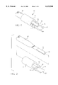
- FIG. 1 is an isometric view of a first embodiment of a surgical cutting device according to the present invention, showing the holder, applanation plate, and cutting blade.
- FIG. 2 is an exploded view of the surgical cutting device of FIG. 1.
- FIG. 3 is a side elevation view of the cutting device of FIG. 1, with the holder shown partially in section.
- FIG. 4 is a top plan view of the device of FIG. 1.
- FIG. 5 is a top plan view of the device of FIG. 1, with an alternative configuration of applanation plate.
- FIG. 6 is a view of a cutting device according to the invention being used to incise the cornea of an eye.
- FIG. 7 illustrates a linear incision effected in the cornea by the present invention, after the blade has been retracted and while the applanation plate is still in contact with the eye.
- FIG. 8 illustrates the shape of the incision of FIG. 7 after the applanation plate has been removed and the eye allowed to return to its preincision contour.
- FIG. 9 is a top plan view of a second embodiment of a surgical cutting device according to the present invention showing a vacuum ring, a holder and a cutting blade.
- FIG. 10 is a section view of the device of FIG. 9, showing the applanation section.
- FIG. 11 is a section detail view of the device of FIG. 10 illustrating a linear incision effected in the cornea by the present invention, after the blade has been retracted and while the vacuum ring and applanation section are still in contact with the eye.
- FIG. 12 illustrates the shape of the incision of FIG. 11 after the vacuum ring and applanation section have been removed and the eye allowed to return to its pre-incision contour.
- FIG. 1 a surgical cutting device 10 according to a first embodiment of the present invention.
- the cutting device 10 comprises a holder 12 and a cutting blade 14.
- the holder 12 is in the form of a hollow cylindrical tube, although the holder 12 may have other convenient shapes without departing from the invention.
- the surface of the holder 12 may, if desired, be knurled or engraved in order to assist the surgeon in grasping the holder and preventing it from slipping during use.
- the holder 12 has a rabbet 16 at its distal end 18, which forms a step 20.
- a tissue contact member Spaced from the step 20 and extending outwardly from the distal end 18 of the holder 12 is a tissue contact member in the form of an applanation plate 22 for contacting tissue to be incised by the cutting blade 14.
- the step 20 serves to control the spacing between the cutting blade 14 and the applanation plate 22 which, in turn, controls the depth of the incision relative to the tissue being incised.
- the cutting blade 14 may be mounted in a handle 24.
- the cutting blade 14 may be removable from the handle 24, so that it may be replaced by a new, sterile blade for each procedure, or it may be integral with the handle 24.
- the surface of the handle 24 may be knurled to assist the surgeon in grasping the handle and preventing it from slipping during use.
- the handle 24 is dimensioned to fit within the holder 12 for reciprocal movement along the longitudinal axis of the holder 12.
- the outer diameter of the handle 24 is just slightly less than the inner diameter of the holder 12 and tapers toward the distal end thereof, so that the handle 24, and thus the cutting blade 14, can be linearly advanced and retracted with respect to the distal end 18 of the holder 12.
- the step 20, in addition to controlling the spacing between the cutting blade 14 and the applanation plate 22, serves to guide the cutting blade 14 for movement in a single plane and prevent the cutting blade 14 from rotating about its longitudinal axis while it is advanced.
- the step 20 also serves as a stop, so that the extent to which the blade 14 may be advanced into tissue relative to the distal end 18 can be limited.
- the step 20 thus cooperates with the handle 24 to prevent the cutting,blade 14 from being advanced beyond a preselected distance determined in part by the distance between the step 20 and the distal end of the handle 24.
- Other ways of guiding the handle 24 and the blade 14 with respect to the holder 12, such as a rib on the handle 24 and a slot on the inner surface of the holder 12 for receiving the rib, and other ways of limiting the extent to which the cutting blade 14 may be advanced, may also be provided without departing from the invention.
- the cutting blade 14 is reciprocally movable with respect to the holder 12, and the cutting blade 14 moves in a linear fashion in and out of the holder 12.
- the cutting blade 14 may be advanced by moving the handle 24 by hand, such as by pushing it between finger and thumb, or by moving the handle 24 by an electric motor or mechanical device such as a gear, worm, or cable.
- the device 10 may be made of any suitable materials.
- the device 10 may be constructed of surgical grade steel, and may be sterilized and reused.
- only the blade 14 may be made of surgical steel, and the remainder of the device 10 may be made of a thermosetting plastic resin material, so as to be relatively inexpensive and disposable after use.
- the holder 12 may be a single integral piece, or may be made of two or more pieces assembled together.
- the dimensions of the device 10 and its constituent elements, and the extent to which the cutting blade 14 may be advanced, are chosen to accommodate the procedures for which the device 10 will be use.
- the cutting blade 14 preferably has a cutting edge 26 which is both beveled and angled with respect to the longitudinal axis of the blade, to facilitate cutting the tissue to be incised.
- any desired blade and edge configuration may be used, depending upon the tissue to be incised and the surgical procedure to be performed.
- the applanation plate 22 preferably has a bull nose, or rounded, end 28, which is placed in contact with tissue to be incised, as will be described in greater detail hereinafter.
- the end 28 of the applanation plate 22 may extend straight across, as shown in FIGS. 1 through 4, or may be concave, as shown in FIG. 5.
- the applanation plate 22' with a concave end 28' shown in FIG. 5 may be of particular utility in ophthalmic surgery, in that the curvature of the concave end 28' may assist the surgeon in placing the applanation plate 22' against the cornea and holding it in place when making the conjunctive flap.
- Other configurations of the end 28 of the applanation plate 22 useful in other surgical procedures may suggest themselves to those skilled in the art and are within the scope of the invention.
- FIGS. 6 through 8 illustrate the use of the device 10 in ophthalmic surgery, although, as noted previously, the invention is not limited to any specific surgical procedure.
- the device 10 is illustrated in connection with making an incision into an eye 30 to create a conjunctive flap.
- the end 28 of the applanation plate 22 is placed against the cornea 32, and sufficient pressure is applied to the cornea to alter its pre-incision contour, as best seen in FIGS. 6 and 7.
- the end 28 of the applanation plate 22 is placed in a location in the area of the limbus, so that the cutting edge of the blade 14 will incise the eye 30 at the corneal border.
- the blade 14 is advanced into the cornea 32 by pushing handle 24 toward the eye, thus incising the cornea. After the incision is made, the blade 14 is retracted by pulling the handle 24 away from the eye.
- the blade 14 Since the blade 14 moves linearly and in a single plane relative to the holder 12, the blade 14 makes an incision 34 which is also linear and lies in a single plane. However, the incision 34 is linear and planar with respect to the tissue only while its contour has been altered due to the pressure applied by the applanation plate 22. Once the applanation plate 22 is removed from the tissue, the tissue relaxes and returns to its pre-incision contour, as illustrated in FIG. 8. When it does so, the incision 34 assumes a multiplane, or stepped, shape as shown in FIG. 8. Thus, the device 10 makes it possible to form a stepped incision by merely advancing and retracting a cutting blade in a linear, planar fashion. No special surgical skills are required, and the resulting incision is precise and accurate. Moreover, the incision is repeatable from procedure to procedure, which gives the surgeon the ability to better anticipate the results of the procedure.
- the depth of the incision into the tissue when the tissue is in its altered state can be controlled by controlling the spacing between the applanation plate 22 and the cutting blade 14.
- an adjustment may be provided to enable the surgeon to selectably control the spacing.
- the cutting device 100 comprises a vacuum ring 102, a holder 104, and a cutting blade 106.
- the cutting blade 106 may be mounted in a handle 108.
- the handle 108 and the cutting blade 106 are linearly movable within the holder 104.
- the vacuum ring comprises an outer housing wall 110 and an inner contact wall 112.
- the contact wall 112 preferably has a concave shape.
- a hollow chamber 114 is formed between the housing wall 110 and the contact wall 112.
- the contact wall 112 includes a plurality of hollow passageways 116 between the hollow chamber 114 and an external surface of the contact wall 112.
- the device 100 also comprises a suction port 118 extending from the housing wall 110 of the vacuum ring 102.
- the suction port 118 includes an internal passage way 120 to the hollow chamber 114.
- the contact wall 112 includes a blade passageway 122 which enables the blade 106 to pass through the contact wall 112 as the blade 106 and the handle 108 are moved linearly into the holder 104.
- the contact wall 112 further includes an applanation section 124 in close proximity to the blade passageway 122. Similar to the applanation plate 22 described above with respect to the first embodiment, the applanation section 124 contacts the tissue to be incised by the cutting blade 106, and is similarly shaped to alter the contour of the cornea.
- the suction port 116 is connected to a vacuum source (not shown).
- the vacuum ring 102 is placed against an eye 126.
- the vacuum source is activated to draw any air from the area between the contact wall 112 and the eye 126 through the passage ways 120 and the hollow chamber 114.
- the cornea 128 is drawn into engagement with the contact wall 112.
- the applanation section 124 applies sufficient pressure to alter the contour of the cornea 128.
- the blade 106 is linearly advanced into the cornea 128 by pushing the handle 108 toward the eye 126, thus incising the cornea 128. After the incision is made, the blade 106 is retracted by pulling the handle 108 away from the eye 126.
- the blade 106 Since the blade 106 moves linearly and in a single plane relative to the holder 104, the blade 106 makes an incision 130 which is also linear and lies in a single plane. However, the incision 130 is linear and planar with respect to the tissue only while its contour is altered due to the pressure applied by the applanation section 124. Once the vacuum is turned off and the applanation section 124 is removed from the tissue, the tissue relaxes and returns to its preincision contour, as illustrated in FIG. 12. When it does so, the incision 130 assumes a multiplane, or stepped, shape as shown in FIG. 12. Thus, the device 100 makes it possible to form a stepped incision by merely advancing and retracting a cutting blade in a linear, planar fashion. No special surgical skills are required, and the resulting incision is precise and accurate. Moreover, the incision is repeatable from procedure to procedure, which gives the surgeon the ability to better anticipate the results of the procedure.
Abstract
Description
Claims (4)
Priority Applications (1)
| Application Number | Priority Date | Filing Date | Title |
|---|---|---|---|
| US09/268,802 US6139560A (en) | 1999-03-16 | 1999-03-16 | Cutting device and method for making controlled surgical incisions |
Applications Claiming Priority (1)
| Application Number | Priority Date | Filing Date | Title |
|---|---|---|---|
| US09/268,802 US6139560A (en) | 1999-03-16 | 1999-03-16 | Cutting device and method for making controlled surgical incisions |
Publications (1)
| Publication Number | Publication Date |
|---|---|
| US6139560A true US6139560A (en) | 2000-10-31 |
Family
ID=23024550
Family Applications (1)
| Application Number | Title | Priority Date | Filing Date |
|---|---|---|---|
| US09/268,802 Expired - Lifetime US6139560A (en) | 1999-03-16 | 1999-03-16 | Cutting device and method for making controlled surgical incisions |
Country Status (1)
| Country | Link |
|---|---|
| US (1) | US6139560A (en) |
Cited By (37)
| Publication number | Priority date | Publication date | Assignee | Title |
|---|---|---|---|---|
| US20030195538A1 (en) * | 1999-10-21 | 2003-10-16 | Medical Instrument Development Laboratories, Inc. | High-speed vitreous cutting system |
| US6663644B1 (en) * | 2000-06-02 | 2003-12-16 | Med-Logics, Inc. | Cutting blade assembly for a microkeratome |
| US20040243160A1 (en) * | 2003-05-27 | 2004-12-02 | Yichieh Shiuey, M.D. | System for cutting the cornea of an eye |
| US20050033338A1 (en) * | 2003-06-19 | 2005-02-10 | Ferree Bret A. | Surgical instruments particularly suited to severing ligaments and fibrous tissues |
| US20050178394A1 (en) * | 2003-08-21 | 2005-08-18 | Intralens Vision, Inc. | Method for keratophakia surgery |
| US20060089607A1 (en) * | 2004-10-22 | 2006-04-27 | Medical Instrument Development Laboratories, Inc. | Ophthalmic cannula insertion tool and method |
| US20060271078A1 (en) * | 2005-05-12 | 2006-11-30 | Modesitt D B | Access and closure device and method |
| US20070027455A1 (en) * | 2004-05-12 | 2007-02-01 | Modesitt D B | Access and closure device and method |
| US20070083221A1 (en) * | 2005-10-12 | 2007-04-12 | Sismed, Llc | Precision trephine |
| US20070083087A1 (en) * | 2005-10-12 | 2007-04-12 | Sismed, Llc | Fixator with membrane |
| US20070280994A1 (en) * | 2006-06-01 | 2007-12-06 | Cunanan Crystal M | Ocular Tissue Separation Areas With Barrier Regions For Inlays Or Other Refractive Procedures |
| US7780689B2 (en) | 2003-04-07 | 2010-08-24 | Technolas Perfect Vision Gmbh | Bar-link drive system for a microkeratome |
| US20110213317A1 (en) * | 2010-03-01 | 2011-09-01 | Chen David E-Bin | Cannula for intraocular surgery |
| US8057541B2 (en) | 2006-02-24 | 2011-11-15 | Revision Optics, Inc. | Method of using small diameter intracorneal inlays to treat visual impairment |
| US8162953B2 (en) | 2007-03-28 | 2012-04-24 | Revision Optics, Inc. | Insertion system for corneal implants |
| US20120191114A1 (en) * | 2009-09-10 | 2012-07-26 | E-Medix Limited | Surgical Knife Handle and Knife |
| US8277418B2 (en) | 2009-12-23 | 2012-10-02 | Alcon Research, Ltd. | Ophthalmic valved trocar cannula |
| US8343106B2 (en) | 2009-12-23 | 2013-01-01 | Alcon Research, Ltd. | Ophthalmic valved trocar vent |
| US8469948B2 (en) | 2010-08-23 | 2013-06-25 | Revision Optics, Inc. | Methods and devices for forming corneal channels |
| US8668735B2 (en) | 2000-09-12 | 2014-03-11 | Revision Optics, Inc. | Corneal implant storage and delivery devices |
| US8900296B2 (en) | 2007-04-20 | 2014-12-02 | Revision Optics, Inc. | Corneal inlay design and methods of correcting vision |
| US8979882B2 (en) | 2008-07-21 | 2015-03-17 | Arstasis, Inc. | Devices, methods, and kits for forming tracts in tissue |
| EP2856956A1 (en) * | 2013-10-02 | 2015-04-08 | Medical Instrument Development Laboratories, Inc. | Cannula insertion tool |
| US9005280B2 (en) | 2000-09-12 | 2015-04-14 | Revision Optics, Inc. | System for packaging and handling an implant and method of use |
| US9198671B2 (en) | 2012-12-04 | 2015-12-01 | DePuy Synthes Products, Inc. | Surgical cutting tool |
| USD746443S1 (en) | 2013-10-02 | 2015-12-29 | Medical Instrument Development Laboratories, Inc. | Cannula insertion tool |
| US9271828B2 (en) | 2007-03-28 | 2016-03-01 | Revision Optics, Inc. | Corneal implant retaining devices and methods of use |
| US9345569B2 (en) | 2011-10-21 | 2016-05-24 | Revision Optics, Inc. | Corneal implant storage and delivery devices |
| US9364260B2 (en) | 2012-05-25 | 2016-06-14 | Depuy Mitek, Llc | Method for atraumatic hip access |
| US9539143B2 (en) | 2008-04-04 | 2017-01-10 | Revision Optics, Inc. | Methods of correcting vision |
| US9549848B2 (en) | 2007-03-28 | 2017-01-24 | Revision Optics, Inc. | Corneal implant inserters and methods of use |
| US10441753B2 (en) | 2012-05-25 | 2019-10-15 | Arstasis, Inc. | Vascular access configuration |
| US10555805B2 (en) | 2006-02-24 | 2020-02-11 | Rvo 2.0, Inc. | Anterior corneal shapes and methods of providing the shapes |
| US10583041B2 (en) | 2015-03-12 | 2020-03-10 | RVO 2.0 Inc. | Methods of correcting vision |
| US10675447B2 (en) | 2012-05-25 | 2020-06-09 | Arstasis, Inc. | Vascular access configuration |
| US10835371B2 (en) | 2004-04-30 | 2020-11-17 | Rvo 2.0, Inc. | Small diameter corneal inlay methods |
| US11633301B2 (en) * | 2018-06-29 | 2023-04-25 | Hatta Kogyo Co., Ltd. | Medical instrument, medical device, method of manufacturing medical instrument, and metal article |
Citations (5)
| Publication number | Priority date | Publication date | Assignee | Title |
|---|---|---|---|---|
| US4180075A (en) * | 1977-04-05 | 1979-12-25 | Marinoff Gerald P | Ophthalmological surgical instrument |
| US4662370A (en) * | 1984-09-13 | 1987-05-05 | Carl-Zeiss-Stiftung | Apparatus for performing lamellar refractive corneal surgery |
| US5080111A (en) * | 1990-06-28 | 1992-01-14 | Pallin Samuel L | Method of making self-sealing episcleral incision |
| US5370652A (en) * | 1992-10-08 | 1994-12-06 | Kellan; Robert E. | Surgical knife blade for making sutureless incisions in the eye and methods therefor |
| US5876415A (en) * | 1997-06-20 | 1999-03-02 | Becton Dickinson And Company | Multi-plane corneal incision form |
-
1999
- 1999-03-16 US US09/268,802 patent/US6139560A/en not_active Expired - Lifetime
Patent Citations (5)
| Publication number | Priority date | Publication date | Assignee | Title |
|---|---|---|---|---|
| US4180075A (en) * | 1977-04-05 | 1979-12-25 | Marinoff Gerald P | Ophthalmological surgical instrument |
| US4662370A (en) * | 1984-09-13 | 1987-05-05 | Carl-Zeiss-Stiftung | Apparatus for performing lamellar refractive corneal surgery |
| US5080111A (en) * | 1990-06-28 | 1992-01-14 | Pallin Samuel L | Method of making self-sealing episcleral incision |
| US5370652A (en) * | 1992-10-08 | 1994-12-06 | Kellan; Robert E. | Surgical knife blade for making sutureless incisions in the eye and methods therefor |
| US5876415A (en) * | 1997-06-20 | 1999-03-02 | Becton Dickinson And Company | Multi-plane corneal incision form |
Cited By (66)
| Publication number | Priority date | Publication date | Assignee | Title |
|---|---|---|---|---|
| US7335217B2 (en) | 1999-10-21 | 2008-02-26 | Medical Instrument Development Laboratories, Inc. | High-speed vitreous cutting system |
| US20030195538A1 (en) * | 1999-10-21 | 2003-10-16 | Medical Instrument Development Laboratories, Inc. | High-speed vitreous cutting system |
| US6663644B1 (en) * | 2000-06-02 | 2003-12-16 | Med-Logics, Inc. | Cutting blade assembly for a microkeratome |
| US9005280B2 (en) | 2000-09-12 | 2015-04-14 | Revision Optics, Inc. | System for packaging and handling an implant and method of use |
| US8668735B2 (en) | 2000-09-12 | 2014-03-11 | Revision Optics, Inc. | Corneal implant storage and delivery devices |
| US9889000B2 (en) | 2000-09-12 | 2018-02-13 | Revision Optics, Inc. | Corneal implant applicators |
| US7780689B2 (en) | 2003-04-07 | 2010-08-24 | Technolas Perfect Vision Gmbh | Bar-link drive system for a microkeratome |
| US20040243159A1 (en) * | 2003-05-27 | 2004-12-02 | Yichieh Shiuey | System for cutting the cornea of an eye |
| WO2004105585A2 (en) | 2003-05-27 | 2004-12-09 | Yichieh Shiuey | System for cutting the cornea of an eye |
| US7901421B2 (en) | 2003-05-27 | 2011-03-08 | Yichieh Shiuey | System for cutting the cornea of an eye |
| US7223275B2 (en) * | 2003-05-27 | 2007-05-29 | Yichieh Shiuey | System for cutting the cornea of an eye |
| US20040243160A1 (en) * | 2003-05-27 | 2004-12-02 | Yichieh Shiuey, M.D. | System for cutting the cornea of an eye |
| US20050033338A1 (en) * | 2003-06-19 | 2005-02-10 | Ferree Bret A. | Surgical instruments particularly suited to severing ligaments and fibrous tissues |
| US20050178394A1 (en) * | 2003-08-21 | 2005-08-18 | Intralens Vision, Inc. | Method for keratophakia surgery |
| US10835371B2 (en) | 2004-04-30 | 2020-11-17 | Rvo 2.0, Inc. | Small diameter corneal inlay methods |
| US20070027455A1 (en) * | 2004-05-12 | 2007-02-01 | Modesitt D B | Access and closure device and method |
| US8002793B2 (en) | 2004-05-12 | 2011-08-23 | Arstasis, Inc. | Access and closure device and method |
| US20070027454A1 (en) * | 2004-05-12 | 2007-02-01 | Modesitt D B | Access and closure device and method |
| US8012168B2 (en) | 2004-05-12 | 2011-09-06 | Arstasis, Inc. | Access and closure device and method |
| US20070032804A1 (en) * | 2004-05-12 | 2007-02-08 | Modesitt D B | Access and closure device and method |
| US8002792B2 (en) | 2004-05-12 | 2011-08-23 | Arstasis, Inc. | Access and closure device and method |
| US20070032803A1 (en) * | 2004-05-12 | 2007-02-08 | Modesitt D B | Access and closure device and method |
| US7998169B2 (en) | 2004-05-12 | 2011-08-16 | Arstasis, Inc. | Access and closure device and method |
| US8002791B2 (en) | 2004-05-12 | 2011-08-23 | Arstasis, Inc. | Access and closure device and method |
| US7604647B2 (en) | 2004-10-22 | 2009-10-20 | Medical Instrument Development Laboratories, Inc. | Ophthalmic cannula insertion tool and method |
| US20060089607A1 (en) * | 2004-10-22 | 2006-04-27 | Medical Instrument Development Laboratories, Inc. | Ophthalmic cannula insertion tool and method |
| US8002794B2 (en) | 2005-05-12 | 2011-08-23 | Arstasis, Inc. | Access and closure device and method |
| US20090318889A1 (en) * | 2005-05-12 | 2009-12-24 | Arstasis, Inc. | Access and closure device and method |
| US8083767B2 (en) | 2005-05-12 | 2011-12-27 | Arstasis, Inc. | Access and closure device and method |
| US8241325B2 (en) | 2005-05-12 | 2012-08-14 | Arstasis, Inc. | Access and closure device and method |
| US20060271078A1 (en) * | 2005-05-12 | 2006-11-30 | Modesitt D B | Access and closure device and method |
| US20070083221A1 (en) * | 2005-10-12 | 2007-04-12 | Sismed, Llc | Precision trephine |
| US20070083087A1 (en) * | 2005-10-12 | 2007-04-12 | Sismed, Llc | Fixator with membrane |
| US8057541B2 (en) | 2006-02-24 | 2011-11-15 | Revision Optics, Inc. | Method of using small diameter intracorneal inlays to treat visual impairment |
| US10555805B2 (en) | 2006-02-24 | 2020-02-11 | Rvo 2.0, Inc. | Anterior corneal shapes and methods of providing the shapes |
| US20070280994A1 (en) * | 2006-06-01 | 2007-12-06 | Cunanan Crystal M | Ocular Tissue Separation Areas With Barrier Regions For Inlays Or Other Refractive Procedures |
| US8162953B2 (en) | 2007-03-28 | 2012-04-24 | Revision Optics, Inc. | Insertion system for corneal implants |
| US8540727B2 (en) | 2007-03-28 | 2013-09-24 | Revision Optics, Inc. | Insertion system for corneal implants |
| US9877823B2 (en) | 2007-03-28 | 2018-01-30 | Revision Optics, Inc. | Corneal implant retaining devices and methods of use |
| US9549848B2 (en) | 2007-03-28 | 2017-01-24 | Revision Optics, Inc. | Corneal implant inserters and methods of use |
| US9271828B2 (en) | 2007-03-28 | 2016-03-01 | Revision Optics, Inc. | Corneal implant retaining devices and methods of use |
| US8900296B2 (en) | 2007-04-20 | 2014-12-02 | Revision Optics, Inc. | Corneal inlay design and methods of correcting vision |
| US9539143B2 (en) | 2008-04-04 | 2017-01-10 | Revision Optics, Inc. | Methods of correcting vision |
| US8979882B2 (en) | 2008-07-21 | 2015-03-17 | Arstasis, Inc. | Devices, methods, and kits for forming tracts in tissue |
| AU2009352530B2 (en) * | 2009-09-10 | 2015-12-03 | Core Surgical Limited | Surgical knife handle and knife |
| US9320651B2 (en) * | 2009-09-10 | 2016-04-26 | Core Surgical Limited | Surgical knife handle and knife |
| US20120191114A1 (en) * | 2009-09-10 | 2012-07-26 | E-Medix Limited | Surgical Knife Handle and Knife |
| US8679064B2 (en) | 2009-12-23 | 2014-03-25 | Alcon Research, Ltd. | Ophthalmic valved trocar cannula |
| US8277418B2 (en) | 2009-12-23 | 2012-10-02 | Alcon Research, Ltd. | Ophthalmic valved trocar cannula |
| US8343106B2 (en) | 2009-12-23 | 2013-01-01 | Alcon Research, Ltd. | Ophthalmic valved trocar vent |
| US20110213317A1 (en) * | 2010-03-01 | 2011-09-01 | Chen David E-Bin | Cannula for intraocular surgery |
| US8469948B2 (en) | 2010-08-23 | 2013-06-25 | Revision Optics, Inc. | Methods and devices for forming corneal channels |
| US9345569B2 (en) | 2011-10-21 | 2016-05-24 | Revision Optics, Inc. | Corneal implant storage and delivery devices |
| US9987124B2 (en) | 2011-10-21 | 2018-06-05 | Revision Optics, Inc. | Corneal implant storage and delivery devices |
| US10675447B2 (en) | 2012-05-25 | 2020-06-09 | Arstasis, Inc. | Vascular access configuration |
| US9364260B2 (en) | 2012-05-25 | 2016-06-14 | Depuy Mitek, Llc | Method for atraumatic hip access |
| US10849649B2 (en) | 2012-05-25 | 2020-12-01 | DePuy Synthes Products, Inc. | Hip obturator and method for atraumatic hip access |
| US10441753B2 (en) | 2012-05-25 | 2019-10-15 | Arstasis, Inc. | Vascular access configuration |
| US9198671B2 (en) | 2012-12-04 | 2015-12-01 | DePuy Synthes Products, Inc. | Surgical cutting tool |
| US9636119B2 (en) | 2012-12-04 | 2017-05-02 | DePuy Synthes Products, Inc. | Surgical cutting tool |
| US9968372B2 (en) | 2013-10-02 | 2018-05-15 | Medical Instrument Development Laboratories, Inc. | Cannula insertion tool |
| USD773651S1 (en) | 2013-10-02 | 2016-12-06 | Medical Instrument Development Laboratories, Inc. | Cannula insertion tool |
| USD746443S1 (en) | 2013-10-02 | 2015-12-29 | Medical Instrument Development Laboratories, Inc. | Cannula insertion tool |
| EP2856956A1 (en) * | 2013-10-02 | 2015-04-08 | Medical Instrument Development Laboratories, Inc. | Cannula insertion tool |
| US10583041B2 (en) | 2015-03-12 | 2020-03-10 | RVO 2.0 Inc. | Methods of correcting vision |
| US11633301B2 (en) * | 2018-06-29 | 2023-04-25 | Hatta Kogyo Co., Ltd. | Medical instrument, medical device, method of manufacturing medical instrument, and metal article |
Similar Documents
| Publication | Publication Date | Title |
|---|---|---|
| US6139560A (en) | Cutting device and method for making controlled surgical incisions | |
| US6139559A (en) | Surgical blade | |
| US5669923A (en) | Anterior capsulotomy device and procedure | |
| US10729582B2 (en) | Vitrectomy probe with end tissue cutter and associated devices, systems, and methods | |
| US6264668B1 (en) | Ophthalmologic instrument for producing a fistula in the sclera | |
| US5019036A (en) | Method and apparatus for removing gelatinous tissue | |
| US5522829A (en) | Surgical cutting instrument | |
| US6083236A (en) | Keratome method and apparatus | |
| US5167618A (en) | Capsulotomy forceps | |
| US5658303A (en) | Universal automated keratectomy apparatus and method | |
| EP0327624A1 (en) | Corneal vacuum trephine system | |
| US7141048B1 (en) | Vitreoretinal instrument | |
| US7285107B1 (en) | Vitreoretinal instrument | |
| EP1325721B1 (en) | Blade for corneal surgery and corneal surgical apparatus comprising the same | |
| US4180075A (en) | Ophthalmological surgical instrument | |
| JP2000501002A (en) | Corneal tissue resection instrument | |
| EP0236485A4 (en) | Scalpel with removable depth guard. | |
| CA2410357C (en) | Cutting blade and cutting blade assembly for ophthalmic procedures | |
| CN111110440B (en) | Device for performing scleral surgical procedures | |
| CA2336028A1 (en) | Apparatus and method for corneal keratotomy | |
| JP4255582B2 (en) | Corneal incision device | |
| US6547802B1 (en) | Surgical blade | |
| EP0165657B1 (en) | Knife for cataract surgery | |
| EP1809219B1 (en) | Surgical knife blade with hollow bevel | |
| US11806281B2 (en) | Ophthalmic surgery instrument |
Legal Events
| Date | Code | Title | Description |
|---|---|---|---|
| STCF | Information on status: patent grant |
Free format text: PATENTED CASE |
|
| FPAY | Fee payment |
Year of fee payment: 4 |
|
| AS | Assignment |
Owner name: CIT HEALTHCARE LLC, NEW YORK Free format text: SECURITY AGREEMENT;ASSIGNORS:TLC VISION (USA) CORPORATION;AMERICAN EYE INSTRUMENT, INC.;LASER EYE SURGERY, INC.;AND OTHERS;REEL/FRAME:019477/0938 Effective date: 20070622 |
|
| AS | Assignment |
Owner name: AMERICAN EYE INSTRUMENT, INC., MISSOURI Free format text: RELEASE BY SECURED PARTY;ASSIGNOR:CIT HEALTHCARE LLC;REEL/FRAME:019995/0296 Effective date: 20071019 Owner name: VALLEY LASER EYE CENTER, LLC, MISSOURI Free format text: RELEASE BY SECURED PARTY;ASSIGNOR:CIT HEALTHCARE LLC;REEL/FRAME:019995/0296 Effective date: 20071019 Owner name: LVCI CALIFORNIA, LLC, MISSOURI Free format text: RELEASE BY SECURED PARTY;ASSIGNOR:CIT HEALTHCARE LLC;REEL/FRAME:019995/0296 Effective date: 20071019 Owner name: MSS, INC., MISSOURI Free format text: RELEASE BY SECURED PARTY;ASSIGNOR:CIT HEALTHCARE LLC;REEL/FRAME:019995/0296 Effective date: 20071019 Owner name: TLC THE LASER CENTER (CAROLINA), INC., MISSOURI Free format text: RELEASE BY SECURED PARTY;ASSIGNOR:CIT HEALTHCARE LLC;REEL/FRAME:019995/0296 Effective date: 20071019 Owner name: SOUTHEAST MEDICAL, INC., MISSOURI Free format text: RELEASE BY SECURED PARTY;ASSIGNOR:CIT HEALTHCARE LLC;REEL/FRAME:019995/0296 Effective date: 20071019 Owner name: TLC MANAGEMENT SERVICES, INC., MISSOURI Free format text: RELEASE BY SECURED PARTY;ASSIGNOR:CIT HEALTHCARE LLC;REEL/FRAME:019995/0296 Effective date: 20071019 Owner name: OR PARTNERS, INC., MISSOURI Free format text: RELEASE BY SECURED PARTY;ASSIGNOR:CIT HEALTHCARE LLC;REEL/FRAME:019995/0296 Effective date: 20071019 Owner name: LASER EYE SURGERY, INC., MISSOURI Free format text: RELEASE BY SECURED PARTY;ASSIGNOR:CIT HEALTHCARE LLC;REEL/FRAME:019995/0296 Effective date: 20071019 Owner name: TLC VISION (USA) CORPORATION, MISSOURI Free format text: RELEASE BY SECURED PARTY;ASSIGNOR:CIT HEALTHCARE LLC;REEL/FRAME:019995/0296 Effective date: 20071019 Owner name: TRUHEARING, INC., MISSOURI Free format text: RELEASE BY SECURED PARTY;ASSIGNOR:CIT HEALTHCARE LLC;REEL/FRAME:019995/0296 Effective date: 20071019 Owner name: TLC THE LASER CENTER (CONNECTICUT) LLC, MISSOURI Free format text: RELEASE BY SECURED PARTY;ASSIGNOR:CIT HEALTHCARE LLC;REEL/FRAME:019995/0296 Effective date: 20071019 Owner name: SOUTHERN OPTHALMICS, INC., MISSOURI Free format text: RELEASE BY SECURED PARTY;ASSIGNOR:CIT HEALTHCARE LLC;REEL/FRAME:019995/0296 Effective date: 20071019 Owner name: TLC THE LASER CENTER (BALTIMORE MANAGEMENT) LLC, M Free format text: RELEASE BY SECURED PARTY;ASSIGNOR:CIT HEALTHCARE LLC;REEL/FRAME:019995/0296 Effective date: 20071019 Owner name: TLC THE LASER CENTER (INSTITUTE), INC., MISSOURI Free format text: RELEASE BY SECURED PARTY;ASSIGNOR:CIT HEALTHCARE LLC;REEL/FRAME:019995/0296 Effective date: 20071019 Owner name: TLC VC, LLC, MISSOURI Free format text: RELEASE BY SECURED PARTY;ASSIGNOR:CIT HEALTHCARE LLC;REEL/FRAME:019995/0296 Effective date: 20071019 Owner name: TLC THE LASER CENTER (NORTHEAST), INC., MISSOURI Free format text: RELEASE BY SECURED PARTY;ASSIGNOR:CIT HEALTHCARE LLC;REEL/FRAME:019995/0296 Effective date: 20071019 Owner name: TLC CAPITAL CORPORATION, MISSOURI Free format text: RELEASE BY SECURED PARTY;ASSIGNOR:CIT HEALTHCARE LLC;REEL/FRAME:019995/0296 Effective date: 20071019 Owner name: TLC WHITTEN LASER EYE ASSOCIATES, LLC, MISSOURI Free format text: RELEASE BY SECURED PARTY;ASSIGNOR:CIT HEALTHCARE LLC;REEL/FRAME:019995/0296 Effective date: 20071019 Owner name: TLC FLORIDA EYE LASER CENTER, LLC, MISSOURI Free format text: RELEASE BY SECURED PARTY;ASSIGNOR:CIT HEALTHCARE LLC;REEL/FRAME:019995/0296 Effective date: 20071019 Owner name: TRUVISION, INC., MISSOURI Free format text: RELEASE BY SECURED PARTY;ASSIGNOR:CIT HEALTHCARE LLC;REEL/FRAME:019995/0296 Effective date: 20071019 Owner name: TLC LASER EYE CENTERS (REFRACTIVE I), INC., MISSOU Free format text: RELEASE BY SECURED PARTY;ASSIGNOR:CIT HEALTHCARE LLC;REEL/FRAME:019995/0296 Effective date: 20071019 Owner name: TLC THE LASER CENTER (BALTIMORE), INC., MISSOURI Free format text: RELEASE BY SECURED PARTY;ASSIGNOR:CIT HEALTHCARE LLC;REEL/FRAME:019995/0296 Effective date: 20071019 Owner name: O.R. PROVIDERS, INC., MISSOURI Free format text: RELEASE BY SECURED PARTY;ASSIGNOR:CIT HEALTHCARE LLC;REEL/FRAME:019995/0296 Effective date: 20071019 Owner name: TLC THE LASER CENTER (BOCA RATON) LP, MISSOURI Free format text: RELEASE BY SECURED PARTY;ASSIGNOR:CIT HEALTHCARE LLC;REEL/FRAME:019995/0296 Effective date: 20071019 Owner name: TLC LASER EYE CENTERS (ATAC), LLC, MISSOURI Free format text: RELEASE BY SECURED PARTY;ASSIGNOR:CIT HEALTHCARE LLC;REEL/FRAME:019995/0296 Effective date: 20071019 Owner name: TLC VISION SOURCE, INC., MISSOURI Free format text: RELEASE BY SECURED PARTY;ASSIGNOR:CIT HEALTHCARE LLC;REEL/FRAME:019995/0296 Effective date: 20071019 Owner name: TRUEVISION PROVIDER ONLINE SERVICES, INC., MISSOUR Free format text: RELEASE BY SECURED PARTY;ASSIGNOR:CIT HEALTHCARE LLC;REEL/FRAME:019995/0296 Effective date: 20071019 Owner name: TLC THE LASER CENTER (ANNAPOLIS), INC., MISSOURI Free format text: RELEASE BY SECURED PARTY;ASSIGNOR:CIT HEALTHCARE LLC;REEL/FRAME:019995/0296 Effective date: 20071019 Owner name: TLC MIDWEST LASER EYE CENTER, INC., MISSOURI Free format text: RELEASE BY SECURED PARTY;ASSIGNOR:CIT HEALTHCARE LLC;REEL/FRAME:019995/0296 Effective date: 20071019 Owner name: TRUVISION CONTACTS, INC., MISSOURI Free format text: RELEASE BY SECURED PARTY;ASSIGNOR:CIT HEALTHCARE LLC;REEL/FRAME:019995/0296 Effective date: 20071019 |
|
| FPAY | Fee payment |
Year of fee payment: 8 |
|
| REMI | Maintenance fee reminder mailed | ||
| FPAY | Fee payment |
Year of fee payment: 12 |