US6071307A - Endoluminal grafts having continuously curvilinear wireforms - Google Patents
Endoluminal grafts having continuously curvilinear wireforms Download PDFInfo
- Publication number
- US6071307A US6071307A US09/163,831 US16383198A US6071307A US 6071307 A US6071307 A US 6071307A US 16383198 A US16383198 A US 16383198A US 6071307 A US6071307 A US 6071307A
- Authority
- US
- United States
- Prior art keywords
- apices
- graft
- curvilinear
- wireform
- wireforms
- Prior art date
- Legal status (The legal status is an assumption and is not a legal conclusion. Google has not performed a legal analysis and makes no representation as to the accuracy of the status listed.)
- Expired - Lifetime
Links
Images


Classifications
-
- A—HUMAN NECESSITIES
- A61—MEDICAL OR VETERINARY SCIENCE; HYGIENE
- A61F—FILTERS IMPLANTABLE INTO BLOOD VESSELS; PROSTHESES; DEVICES PROVIDING PATENCY TO, OR PREVENTING COLLAPSING OF, TUBULAR STRUCTURES OF THE BODY, e.g. STENTS; ORTHOPAEDIC, NURSING OR CONTRACEPTIVE DEVICES; FOMENTATION; TREATMENT OR PROTECTION OF EYES OR EARS; BANDAGES, DRESSINGS OR ABSORBENT PADS; FIRST-AID KITS
- A61F2/00—Filters implantable into blood vessels; Prostheses, i.e. artificial substitutes or replacements for parts of the body; Appliances for connecting them with the body; Devices providing patency to, or preventing collapsing of, tubular structures of the body, e.g. stents
- A61F2/02—Prostheses implantable into the body
- A61F2/04—Hollow or tubular parts of organs, e.g. bladders, tracheae, bronchi or bile ducts
- A61F2/06—Blood vessels
- A61F2/07—Stent-grafts
-
- A—HUMAN NECESSITIES
- A61—MEDICAL OR VETERINARY SCIENCE; HYGIENE
- A61F—FILTERS IMPLANTABLE INTO BLOOD VESSELS; PROSTHESES; DEVICES PROVIDING PATENCY TO, OR PREVENTING COLLAPSING OF, TUBULAR STRUCTURES OF THE BODY, e.g. STENTS; ORTHOPAEDIC, NURSING OR CONTRACEPTIVE DEVICES; FOMENTATION; TREATMENT OR PROTECTION OF EYES OR EARS; BANDAGES, DRESSINGS OR ABSORBENT PADS; FIRST-AID KITS
- A61F2/00—Filters implantable into blood vessels; Prostheses, i.e. artificial substitutes or replacements for parts of the body; Appliances for connecting them with the body; Devices providing patency to, or preventing collapsing of, tubular structures of the body, e.g. stents
- A61F2/95—Instruments specially adapted for placement or removal of stents or stent-grafts
-
- A—HUMAN NECESSITIES
- A61—MEDICAL OR VETERINARY SCIENCE; HYGIENE
- A61F—FILTERS IMPLANTABLE INTO BLOOD VESSELS; PROSTHESES; DEVICES PROVIDING PATENCY TO, OR PREVENTING COLLAPSING OF, TUBULAR STRUCTURES OF THE BODY, e.g. STENTS; ORTHOPAEDIC, NURSING OR CONTRACEPTIVE DEVICES; FOMENTATION; TREATMENT OR PROTECTION OF EYES OR EARS; BANDAGES, DRESSINGS OR ABSORBENT PADS; FIRST-AID KITS
- A61F2/00—Filters implantable into blood vessels; Prostheses, i.e. artificial substitutes or replacements for parts of the body; Appliances for connecting them with the body; Devices providing patency to, or preventing collapsing of, tubular structures of the body, e.g. stents
- A61F2/82—Devices providing patency to, or preventing collapsing of, tubular structures of the body, e.g. stents
- A61F2/86—Stents in a form characterised by the wire-like elements; Stents in the form characterised by a net-like or mesh-like structure
- A61F2/89—Stents in a form characterised by the wire-like elements; Stents in the form characterised by a net-like or mesh-like structure the wire-like elements comprising two or more adjacent rings flexibly connected by separate members
-
- A—HUMAN NECESSITIES
- A61—MEDICAL OR VETERINARY SCIENCE; HYGIENE
- A61F—FILTERS IMPLANTABLE INTO BLOOD VESSELS; PROSTHESES; DEVICES PROVIDING PATENCY TO, OR PREVENTING COLLAPSING OF, TUBULAR STRUCTURES OF THE BODY, e.g. STENTS; ORTHOPAEDIC, NURSING OR CONTRACEPTIVE DEVICES; FOMENTATION; TREATMENT OR PROTECTION OF EYES OR EARS; BANDAGES, DRESSINGS OR ABSORBENT PADS; FIRST-AID KITS
- A61F2/00—Filters implantable into blood vessels; Prostheses, i.e. artificial substitutes or replacements for parts of the body; Appliances for connecting them with the body; Devices providing patency to, or preventing collapsing of, tubular structures of the body, e.g. stents
- A61F2/02—Prostheses implantable into the body
- A61F2/04—Hollow or tubular parts of organs, e.g. bladders, tracheae, bronchi or bile ducts
- A61F2/06—Blood vessels
- A61F2/07—Stent-grafts
- A61F2002/075—Stent-grafts the stent being loosely attached to the graft material, e.g. by stitching
-
- A—HUMAN NECESSITIES
- A61—MEDICAL OR VETERINARY SCIENCE; HYGIENE
- A61F—FILTERS IMPLANTABLE INTO BLOOD VESSELS; PROSTHESES; DEVICES PROVIDING PATENCY TO, OR PREVENTING COLLAPSING OF, TUBULAR STRUCTURES OF THE BODY, e.g. STENTS; ORTHOPAEDIC, NURSING OR CONTRACEPTIVE DEVICES; FOMENTATION; TREATMENT OR PROTECTION OF EYES OR EARS; BANDAGES, DRESSINGS OR ABSORBENT PADS; FIRST-AID KITS
- A61F2250/00—Special features of prostheses classified in groups A61F2/00 - A61F2/26 or A61F2/82 or A61F9/00 or A61F11/00 or subgroups thereof
- A61F2250/0004—Special features of prostheses classified in groups A61F2/00 - A61F2/26 or A61F2/82 or A61F9/00 or A61F11/00 or subgroups thereof adjustable
- A61F2250/001—Special features of prostheses classified in groups A61F2/00 - A61F2/26 or A61F2/82 or A61F9/00 or A61F11/00 or subgroups thereof adjustable for adjusting a diameter
Definitions
- the present invention relates generally to medical devices, and more particularly to a radially expandable, endoluminal grafts which may be implanted within the lumen of a luminal anatomical structure.
- radially expandable grafts and similar devices within body lumens (e.g., blood vessels, esophagus, common bile duct, ureter, urethra, fallopian tube, etc.)
- body lumens e.g., blood vessels, esophagus, common bile duct, ureter, urethra, fallopian tube, etc.
- Self-expanding intraluminal grafts are formed of resilient or shape-memory material such as spring steel or NitinolTM. Self-expanding material is capable of being formed in a configuration from which it may be compressed to a radially compact diameter for placement within a damaged vessel. At the time of use, the memory feature of these materials causes them to self-expand from the radially compact diameter to the expanded operative diameter.
- Pressure-expandable intraluminal grafts are formed of plastically deformable material such as stainless steel that is initially formed in its radially compact diameter. This type of material does not have memory, and will remain in the radially compact diameter until manually expanded. Typically, outwardly directed pressure is exerted upon the graft through use of a balloon so as to cause radial expansion and resultant plastic deformation of the material to its operative diameter.
- endovascular grafts typically comprise: a tube of pliable material (e.g., expanded polytetrafluoroethylene (ePTFE) or woven polyester) in combination with a graft anchoring component (e.g., a wireform, a frame, a series of wire rings, hooks, barbs, clips, staples, etc.) which operates to hold the tubular graft in its intended position within the blood vessel.
- a tube of pliable material e.g., expanded polytetrafluoroethylene (ePTFE) or woven polyester
- a graft anchoring component e.g., a wireform, a frame, a series of wire rings, hooks, barbs, clips, staples, etc.
- the graft anchoring component is formed of a radially expandable frame (e.g., one or more radially-expandable wireforms of the type described hereabove) which is either a) incorporated into the body of the tubular graft or b) formed separately from the graft and positioned within the graft lumen, such frame being expandable to exert outwardly directed radial pressure against the surrounding blood vessel wall--thereby frictionally holding the graft in place.
- a radially expandable frame e.g., one or more radially-expandable wireforms of the type described hereabove
- endovascular grafts which incorporate radially expandable graft anchoring devices are initially disposed in a radially collapsed configuration which is sufficiently compact to allow the graft to be transluminally advanced through the vasculature until it reaches the intended site of implantation. Thereafter, the graft (and the accompanying graft anchoring device) expands to a radially expanded configuration which is large enough to exert the desired outwardly-directed pressure against the blood vessel wall.
- hooks, barbs, or other projections formed on the graft anchoring device will insert into the wall of the blood vessel to ensure that the graft will be firmly held in its desired position, without slipping or migrating after implantation.
- the radially expandable anchoring devices e.g., frames or wireforms
- the radially expandable anchoring devices are generally classifiable as either a.) self-expanding or b) pressure-expandable.
- Graft anchoring devices of the self-expanding type are usually formed of a resilient material (e.g., spring metal) or shape memory alloy which automatically expands from a radially collapsed configuration to a radially expanded configuration, when relieved of surrounding constraint (e.g., a surrounding tubular sheath or catheter wall).
- a resilient material e.g., spring metal
- shape memory alloy which automatically expands from a radially collapsed configuration to a radially expanded configuration, when relieved of surrounding constraint (e.g., a surrounding tubular sheath or catheter wall).
- those of the pressure-expandable variety are typically formed of malleable wire or other plastically deformable material which will deform to a radially expanded configuration in response to the exertion of outwardly directed pressure thereagainst--as by inflation of a balloon or actuation of another pressure-exerting apparatus which has been positioned within the graft anchoring device.
- the diameter of the graft In order to facilitate the transluminal, catheter based implantation of endoluminal grafts, it is typically desirable to minimize the diameter of the graft while in its radially compact configuration, thereby minimizing the required diameter of the delivery catheter used for delivery and implantation of the graft.
- the smaller the diameter of the delivery catheter the smaller the size of the percutaneous puncture tract required for introduction of the catheter.
- the act of radially compressing or collapsing a graft can result in the introduction of stress within the wireform. In some cases, the introduction of such stresses can adversely affect the performance of the graft following implantation.
- the present invention provides new grafts which are constructed to be radially collapsed and/or radially compressed to a small diameter.
- the wireforms of the present invention generally comprise a wire deformed into generally annular configuration and consisting of a plurality of curvilinear wave forms.
- the wave forms have a plurality of first apices in linear alignment with each other, a plurality of second apices in linear alignment with each other, and a plurality of curvilinear segments traversing back and forth between said first and second apices.
- This graft is i) initially disposable in a radially compact configuration of a first diameter and ii) subsequently expandable to a radially expanded configuration of a second diameter, said second diameter being larger than said first diameter.
- the adjacent curvilinear segments of the wireforms will nest or seat in abutting contact with one another, thereby minimizing the diameter of the graft while in its radially compact configuration.
- endoluminal or endovascular grafts which comprise one or more wireforms of the foregoing character, affixed to a pliable tubular graft such that the wireforms will act as a radially expandable graft anchoring device to frictionally anchor and hold the graft at its desired position within the lumen of a blood vessel or other anatomical conduit.
- FIG. 1 is a schematic view of a human body having an endoluminal graft of the present invention implanted within the abdominal aorta, to treat an aortic aneurysm.
- FIG. 2 is a side elevational view of an endoluminal graft of the present invention, showing the locations and configurations of the continuously curvilinear members mounted within the graft.
- FIG. 3 is a longitudinal sectional view of the endoluminal graft of FIG. 2.
- FIG. 4 is a plan view of one (1) of the continuously curvilinear members of the endoluminal graft of FIG. 2.
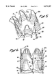
- FIG. 5 is perspective view of one end of the endoluminal graft of FIG. 2.
- FIG. 6 is a side elevational view of the endoluminal graft of FIG. 2.
- FIG. 7 is a plan view of a fixture apparatus of the present invention being used to perform a first step in the formation of a continuously curvilinear member of the present invention.
- FIG. 8 is a perspective view of a wireform guide member which is a component of the fixture apparatus of FIG. 7.
- FIG. 9 is a perspective view of one end of a cylindrical mandrel being used to perform a second step in the formation of a continuously curvilinear member of the present invention.
- FIGS. 1-6 show an endoluminal graft 100 of the present invention, which comprises a pliable tube 22 having a plurality of radially expandable ring members 10 affixed thereto.
- the radially expandable ring members 10 combine to form a graft anchoring system (i.e., a series of individual ring members 10) which, when radially expanded within the lumen of an anatomical conduit, will exert outward force against the surrounding wall of the anatomical conduit to hold the endoluminal graft 100 in a substantially fixed position therewithin.
- a graft anchoring system i.e., a series of individual ring members
- each ring member 10 comprises a series of curvilinear segments 12, 14 which extend, in zig-zag fashion, between apices 16, 18.
- a tangent line TL is projectable in relation to each curvilinear segment 12 or 14, and the direction in which the curvilinear segment 12, 14 diverges from its tangent line TL is herein referred to as its direction of curvature DC.
- a center of radius CR is definable within each apex 16, 18, and a longitudinal apical axis LAA may be projected through each center of radius CR, as shown.
- An internal angle A 1 of preferably about 37.5 degrees, and an external angle A 2 of preferably about 70 degrees, are defined between each longitudinal apical axis LAA and the adjacent tangent lines TL which relate to the curvilinear segments 12, 14 on either side of that longitudinal apical axis LAA.
- Each curvilinear segment 12, 14 connects to the curvilinear first and second apices 16, 18 at points of tangency.
- the internal angle A 1 is the angle that each of the tangent lines TL make with respect to the adjacent longitudinal apical axes LAA
- the external angle A 2 is the angle with respect to the corresponding LAA along the respective curvilinear first and second apices 16, 18 at which the points of tangency are located.
- the values of the internal angle A 1 and the external angle A 2 are not limited to the described preferred embodiments and it will be understood by those skilled in the art that other values also within the scope of the present invention.
- each ring member 10 As shown in FIG. 9, the individual curvilinear segments 12, 14 of each ring member 10 are affixed to or continuous with one another, and are formed about a longitudinal axis LA to form a ring.
- the ring members 10 may be either pressure expandable or self expanding.
- Ring members 10 of the pressure-expandable (i.e., "passive expandable”) variety may be formed of plastically deformable material (e.g., stainless steel or ElgiloyTM) which is compressible and plastically deformable to a first (radially compact) diameter and remains stable in such first diameter until such time as outwardly directed pressure is applied thereto (e.g., by inflation of a balloon positioned within the interior of the radially collapsed ring member) to cause radial expansion and resultant plastic deformation to a second (operative) diameter.
- plastically deformable material e.g., stainless steel or ElgiloyTM
- Ring members 10 of the self-expanding variety may be formed of resilient or shape memory material (e.g., spring steel or NitinolTM) which is capable of self-expanding from its first (radially compact) diameter to its second (operative) diameter without the exertion of outwardly directed force thereagainst.
- resilient or shape memory material e.g., spring steel or NitinolTM
- Each ring member 10 may thus be used individually as a radially expandable intraluminal stent, whereby the alternating zig-zag configuration of the curvilinear members 12, 14 will form a support scaffold which will prevent surrounding tissue from invading the interior thereof.
- the ring members 10 comprise stents which may be implanted in blood vessels or other luminal anatomical structures to maintain patency thereof.
- the ring member 10 When it is desired to use a ring member 10 as a stent, the ring member 10 may be initially mounted upon or within a delivery catheter for introduction into, and implantation within, the desired anatomical structure. In pressure-expandable embodiments, by way of example and not limitation this may be accomplished by mounting the ring member 10 in a radially compressed state upon a balloon catheter, while the balloon of the catheter is deflated. Thereafter, the catheter is inserted and advanced through the body lumens (e.g., blood vessels) until the ring member 10 is positioned at the desired site of implantation. Thereafter, the balloon of the catheter is inflated causing the ring member 10 to radially expand until it engages the surrounding wall of the anatomical structure (e.g., blood vessel).
- the body lumens e.g., blood vessels
- the balloon is deflated and the catheter is removed, leaving the ring member implanted as a stent within the luminal anatomical structure (e.g., blood vessel).
- a stent within the luminal anatomical structure (e.g., blood vessel).
- Self-expanding embodiments and any known methods of their implantation are also within the scope of the present invention.
- FIGS. 1-3 and 5-6 show an endoluminal graft 100 wherein a plurality of the ring members 10 of the present invention are used to form a graft anchoring system.
- the endoluminal graft 100 comprises a pliable tube graft 22 having a series of the ring members 10 affixed to the tube graft 22 at spaced-apart locations or intervals, as shown.
- the apices 16, 18 of the ring members 10 are preferably in direct alignment with one another and the curvilinear segments 12, 14 are also substantially aligned and are of the substantially the same direction of curvature DC.
- the pliable tube graft 22 may be formed of any suitable material, including but not limited to woven polyester, expanded polytetrafluoroethylene (ePTFE), etc.
- the tube graft 22 is formed of woven polyester and the individual ring members 10 are threaded through slits 40 formed in the tube graft 22 such that the ring members 10 will be held in substantially fixed positions within the tube graft 22.
- the ring members 10 may be unconnected to one another other than by way of their common attachment to the pliable tube graft. On the other hand, if desired, they may be attached to one another other than by way of their common attachment to the pliable tube graft.
- terminal ring members 10 E located at either end of the endoluminal graft 100 such that their first apices 16 protrude beyond the end of the tube graft 22, as particularly shown in FIGS. 5 and 6.
- the protruding portions of the terminal ring members 10 E may be bent outwardly in the manner indicated by phantom lines on FIG. 5, to enhance the frictional engagement of those terminal ring members 10 E with the tissue of the surrounding wall of the anatomical structure.
- the protruding portions 10 E are described in great details in U.S. Pat. No. 5,782,904 to White et al., which is incorporated herein by reference.
- FIGS. 7-9 show a fixture apparatus and method for forming a ring member 10 of the present invention from a single piece of wire 57.
- the preferred fixture apparatus 50 comprises a backboard 52 which has a flat surface 53 and a plurality of wire-forming block members 54 mounted on such flat surface 53.
- Each block member 54 has a curved wire-abutting edge 56, an apical tip 58, and an apical trough 60.
- the block members 54 are mounted on the back board 52 such that the apical tip 58 of one block member 54 is in close-spaced juxtaposition with the apical trough 60 of the next block member 54, as shown.
- the distance between the apical tip 58 of one block member 54 and the apical trough 60 of the next block member 54 is approximately equal to the diameter of the wire 57.
- a preferred wire 57 for use in forming the ring members 10 is an alloy wire available commercially as ElgiloyTM wire from Elgiloy, Elgin, Ill.
- Other wires which may be useable include stainless steel wire and other implantable metals.
- the wire 57 is threaded between the block members 54 such that the wire 57 abuts against the curved surfaces 56 to form the curvilinear segments 12, 14, and is interposed between the adjacent apical tips 58 and apical troughs 60 to form the first and second apices 16, 18. In this manner, the wire 57 assumes the desired flattened wireform configuration shown in FIG. 4.
- the wire 57 As shown specifically in FIG. 9, after the wire 57 has been formed upon the fixture apparatus 50, it is removed from the fixture apparatus 52 and is the formed about a cylindrical mandrel 70 to impart the desired ring configuration.
- the free ends tails 24, 26 of the wire 57 When formed about the mandrel 70, the free ends tails 24, 26 of the wire 57 are in side by side juxtaposition. Such free end tails 24, 26 are then twined about one another to overlap and a sleeve member 30 is crimped thereabout to firmly connect the twined portions of the free end tails 24, 26 immediately adjacent the associated second apex 18. Thereafter any portions of the free end tails 24, 26 which protrude from the crimped sleeve member 30 may be cut away, and the finished ring member 10 is removed from the mandrel 70.
- the plurality of curvilinear segments of each ring member may be initially formed as separate, curvilinear segments and subsequently connected to one another to form that ring member.
Abstract
Description
Claims (26)
Priority Applications (8)
| Application Number | Priority Date | Filing Date | Title |
|---|---|---|---|
| US09/163,831 US6071307A (en) | 1998-09-30 | 1998-09-30 | Endoluminal grafts having continuously curvilinear wireforms |
| EP99951621A EP1124505B2 (en) | 1998-09-30 | 1999-09-24 | Endoluminal grafts having continuously curvilinear wireforms |
| JP2000571847A JP2002531148A (en) | 1998-09-30 | 1999-09-24 | Endoluminal implant with continuous curved wireform |
| DE69924400T DE69924400T3 (en) | 1998-09-30 | 1999-09-24 | ENDOLUMINAL TISSUE WITH CONTINUOUS CURVED LINEAR WIRE SHAPES |
| PCT/US1999/022400 WO2000018324A2 (en) | 1998-09-30 | 1999-09-24 | Endoluminal grafts having continuously curvilinear wireforms |
| CA002345962A CA2345962C (en) | 1998-09-30 | 1999-09-24 | Endoluminal grafts having continuously curvilinear wireforms |
| AU64025/99A AU762866B2 (en) | 1998-09-30 | 1999-09-24 | Endoluminal grafts having continuously curvilinear wireforms |
| JP2008094313A JP2008173499A (en) | 1998-09-30 | 2008-03-31 | Endoluminal graft having continuously curvilinear wireforms |
Applications Claiming Priority (1)
| Application Number | Priority Date | Filing Date | Title |
|---|---|---|---|
| US09/163,831 US6071307A (en) | 1998-09-30 | 1998-09-30 | Endoluminal grafts having continuously curvilinear wireforms |
Publications (1)
| Publication Number | Publication Date |
|---|---|
| US6071307A true US6071307A (en) | 2000-06-06 |
Family
ID=22591772
Family Applications (1)
| Application Number | Title | Priority Date | Filing Date |
|---|---|---|---|
| US09/163,831 Expired - Lifetime US6071307A (en) | 1998-09-30 | 1998-09-30 | Endoluminal grafts having continuously curvilinear wireforms |
Country Status (7)
| Country | Link |
|---|---|
| US (1) | US6071307A (en) |
| EP (1) | EP1124505B2 (en) |
| JP (2) | JP2002531148A (en) |
| AU (1) | AU762866B2 (en) |
| CA (1) | CA2345962C (en) |
| DE (1) | DE69924400T3 (en) |
| WO (1) | WO2000018324A2 (en) |
Cited By (60)
| Publication number | Priority date | Publication date | Assignee | Title |
|---|---|---|---|---|
| WO2001030270A2 (en) | 1999-09-23 | 2001-05-03 | Edwards Lifesciences Corporation | Pre-shaped intraluminal graft |
| US6278079B1 (en) * | 1999-02-09 | 2001-08-21 | Edwards Lifesciences Corp. | Laser cutting of fabric grafts |
| US6290720B1 (en) * | 1998-11-16 | 2001-09-18 | Endotex Interventional Systems, Inc. | Stretchable anti-buckling coiled-sheet stent |
| US6322585B1 (en) | 1998-11-16 | 2001-11-27 | Endotex Interventional Systems, Inc. | Coiled-sheet stent-graft with slidable exo-skeleton |
| US6331188B1 (en) * | 1994-08-31 | 2001-12-18 | Gore Enterprise Holdings, Inc. | Exterior supported self-expanding stent-graft |
| US20020058984A1 (en) * | 1998-03-30 | 2002-05-16 | Frank Butaric | Extension prosthesis for an arterial repair |
| US20020058985A1 (en) * | 2000-11-16 | 2002-05-16 | Depalma Donald F. | Thoracic aneurysm repair prosthesis and system |
| US20030033002A1 (en) * | 1998-09-30 | 2003-02-13 | Edwards Lifesciences, Llc | Aorto uni-iliac graft |
| US20030088305A1 (en) * | 2001-10-26 | 2003-05-08 | Cook Incorporated | Prostheses for curved lumens |
| US20030158595A1 (en) * | 2002-02-20 | 2003-08-21 | Impra, Inc., A Subsidiary Of C.R. Bard Inc. | Anchoring device for an endoluminal prosthesis |
| US6626938B1 (en) * | 2000-11-16 | 2003-09-30 | Cordis Corporation | Stent graft having a pleated graft member |
| US20030191517A1 (en) * | 2002-04-03 | 2003-10-09 | Osborne Thomas A. | Intraluminal graft assembly and vessel repair system |
| US6641607B1 (en) | 2000-12-29 | 2003-11-04 | Advanced Cardiovascular Systems, Inc. | Double tube stent |
| US20040059406A1 (en) * | 2002-09-20 | 2004-03-25 | Cully Edward H. | Medical device amenable to fenestration |
| US20040106972A1 (en) * | 2000-11-20 | 2004-06-03 | Deaton David H. | Fenestrated endovascular graft |
| US6805706B2 (en) | 2002-08-15 | 2004-10-19 | Gmp Cardiac Care, Inc. | Stent-graft with rails |
| US6805704B1 (en) | 2000-06-26 | 2004-10-19 | C. R. Bard, Inc. | Intraluminal stents |
| US20050267566A1 (en) * | 2003-03-26 | 2005-12-01 | Robert Rioux | Longitudinally expanding medical device |
| US20060195177A1 (en) * | 2003-08-12 | 2006-08-31 | Jotec Gmbh | Stent for implantation in a blood vessel, especially in the region of the aortic arch |
| US20060276872A1 (en) * | 2003-09-03 | 2006-12-07 | Bolton Medical, Inc. | Method for implanting a prosthesis with a two-part expanding delivery system |
| US20080077226A1 (en) * | 2003-09-03 | 2008-03-27 | Bolton Medical, Inc. | Stent Graft Delivery System Handle |
| US20080114445A1 (en) * | 2006-10-24 | 2008-05-15 | Cook Incorporated | Thoracic arch stent graft and method of delivery |
| US20080119943A1 (en) * | 2006-11-16 | 2008-05-22 | Armstrong Joseph R | Stent having flexibly connected adjacent stent elements |
| US20080264102A1 (en) * | 2004-02-23 | 2008-10-30 | Bolton Medical, Inc. | Sheath Capture Device for Stent Graft Delivery System and Method for Operating Same |
| EP1986573A2 (en) * | 2006-02-03 | 2008-11-05 | Bolton Medical Inc. | Delivery system and meth0d for self-centering a proximal end of a stent graft |
| US20090112306A1 (en) * | 2007-10-24 | 2009-04-30 | Craig Bonsignore | Stent segments axially connected by thin film |
| US20090171437A1 (en) * | 2007-12-26 | 2009-07-02 | Cook Incorporated | Low profile non-symmetrical stent |
| US20090299403A1 (en) * | 2006-05-02 | 2009-12-03 | C.R. Bard, Inc. | Ivc filter with translating hooks |
| US20090306763A1 (en) * | 2007-12-26 | 2009-12-10 | Roeder Blayne A | Low profile non-symmetrical bare alignment stents with graft |
| US20100030255A1 (en) * | 2008-06-30 | 2010-02-04 | Humberto Berra | Abdominal aortic aneurysms: systems and methods of use |
| US20100100170A1 (en) * | 2008-10-22 | 2010-04-22 | Boston Scientific Scimed, Inc. | Shape memory tubular stent with grooves |
| GB2470041A (en) * | 2009-05-06 | 2010-11-10 | William Cook Europe As | Stent graft |
| US20100312326A1 (en) * | 2007-12-26 | 2010-12-09 | Cook Incorporated | Apparatus and methods for deployment of a modular stent-graft system |
| US20100318179A1 (en) * | 2007-12-21 | 2010-12-16 | Feinstein Ara J | Devices, systems, and methods for repair of vascular defects |
| US20110118821A1 (en) * | 2007-12-26 | 2011-05-19 | Cook Incorporated | Low profile non-symmetrical stent |
| US20110118816A1 (en) * | 2009-11-18 | 2011-05-19 | William Cook Europe Aps | Stent Graft and Introducer Assembly |
| US20110125249A1 (en) * | 2009-11-19 | 2011-05-26 | Med Institute, Inc. | Stent Graft and Introducer Assembly |
| US20110125244A1 (en) * | 2009-11-18 | 2011-05-26 | Roeder Blayne A | Stent graft and introducer assembly |
| US20120143305A1 (en) * | 2003-09-03 | 2012-06-07 | Bolton Medical, Inc. | Vascular repair devices |
| US8372109B2 (en) | 2004-08-04 | 2013-02-12 | C. R. Bard, Inc. | Non-entangling vena cava filter |
| US8430903B2 (en) | 2005-08-09 | 2013-04-30 | C. R. Bard, Inc. | Embolus blood clot filter and delivery system |
| US8574261B2 (en) | 2005-05-12 | 2013-11-05 | C. R. Bard, Inc. | Removable embolus blood clot filter |
| US8613754B2 (en) | 2005-05-12 | 2013-12-24 | C. R. Bard, Inc. | Tubular filter |
| US8679173B2 (en) | 2009-03-16 | 2014-03-25 | Cook Medical Technologies Llc | Hybrid stent and method of making such a stent |
| US8690906B2 (en) | 1998-09-25 | 2014-04-08 | C.R. Bard, Inc. | Removeable embolus blood clot filter and filter delivery unit |
| US8728145B2 (en) | 2008-12-11 | 2014-05-20 | Cook Medical Technologies Llc | Low profile non-symmetrical stents and stent-grafts |
| US8998970B2 (en) | 2012-04-12 | 2015-04-07 | Bolton Medical, Inc. | Vascular prosthetic delivery device and method of use |
| US9101506B2 (en) | 2009-03-13 | 2015-08-11 | Bolton Medical, Inc. | System and method for deploying an endoluminal prosthesis at a surgical site |
| US9131999B2 (en) | 2005-11-18 | 2015-09-15 | C.R. Bard Inc. | Vena cava filter with filament |
| US9204956B2 (en) | 2002-02-20 | 2015-12-08 | C. R. Bard, Inc. | IVC filter with translating hooks |
| US9220617B2 (en) | 2003-09-03 | 2015-12-29 | Bolton Medical, Inc. | Dual capture device for stent graft delivery system and method for capturing a stent graft |
| US9326842B2 (en) | 2006-06-05 | 2016-05-03 | C. R . Bard, Inc. | Embolus blood clot filter utilizable with a single delivery system or a single retrieval system in one of a femoral or jugular access |
| US9439751B2 (en) | 2013-03-15 | 2016-09-13 | Bolton Medical, Inc. | Hemostasis valve and delivery systems |
| US20160270899A1 (en) * | 2007-12-21 | 2016-09-22 | Cook Medical Technologies Llc | Devices, systems, and methods for repair of vascular defects |
| US9943428B2 (en) | 2008-01-11 | 2018-04-17 | W. L. Gore & Associates, Inc. | Stent having adjacent elements connected by flexible webs |
| US10188496B2 (en) | 2006-05-02 | 2019-01-29 | C. R. Bard, Inc. | Vena cava filter formed from a sheet |
| US10299948B2 (en) | 2014-11-26 | 2019-05-28 | W. L. Gore & Associates, Inc. | Balloon expandable endoprosthesis |
| US10568752B2 (en) | 2016-05-25 | 2020-02-25 | W. L. Gore & Associates, Inc. | Controlled endoprosthesis balloon expansion |
| US11259945B2 (en) | 2003-09-03 | 2022-03-01 | Bolton Medical, Inc. | Dual capture device for stent graft delivery system and method for capturing a stent graft |
| US11596537B2 (en) | 2003-09-03 | 2023-03-07 | Bolton Medical, Inc. | Delivery system and method for self-centering a proximal end of a stent graft |
Families Citing this family (3)
| Publication number | Priority date | Publication date | Assignee | Title |
|---|---|---|---|---|
| AU2007200411B2 (en) * | 1999-01-22 | 2008-05-29 | W. L. Gore & Associates, Inc. | Low profile stent and graft combination |
| AU2006335649A1 (en) * | 2006-01-13 | 2007-07-19 | I.B.S. International Biomedical Systems S.P.A. | Endovascular prosthesis and relating manufacturing procedure |
| JP7039957B2 (en) * | 2017-11-24 | 2022-03-23 | 株式会社ジェイ・エム・エス | Stent |
Citations (35)
| Publication number | Priority date | Publication date | Assignee | Title |
|---|---|---|---|---|
| US2978787A (en) * | 1957-04-18 | 1961-04-11 | Meadox Medicals Inc | Synthetic vascular implants and the manufacture thereof |
| US5064435A (en) * | 1990-06-28 | 1991-11-12 | Schneider (Usa) Inc. | Self-expanding prosthesis having stable axial length |
| US5123917A (en) * | 1990-04-27 | 1992-06-23 | Lee Peter Y | Expandable intraluminal vascular graft |
| US5135536A (en) * | 1991-02-05 | 1992-08-04 | Cordis Corporation | Endovascular stent and method |
| US5397345A (en) * | 1983-12-09 | 1995-03-14 | Endovascular Technologies, Inc. | Artificial graft and implantation method |
| EP0657147A2 (en) * | 1993-11-04 | 1995-06-14 | C.R. Bard, Inc. | Non-migrating vascular prosthesis and minimally invasive placement system therefor |
| EP0662307A1 (en) * | 1993-12-28 | 1995-07-12 | Advanced Cardiovascular Systems, Inc. | Expandable stents and method for making same |
| US5443497A (en) * | 1993-11-22 | 1995-08-22 | The Johns Hopkins University | Percutaneous prosthetic by-pass graft and method of use |
| EP0686379A2 (en) * | 1994-06-08 | 1995-12-13 | Cardiovascular Concepts, Inc. | Apparatus for endoluminal graft placement |
| US5489295A (en) * | 1991-04-11 | 1996-02-06 | Endovascular Technologies, Inc. | Endovascular graft having bifurcation and apparatus and method for deploying the same |
| EP0701800A1 (en) * | 1994-09-15 | 1996-03-20 | C.R. Bard, Inc. | Method and apparatus for recapture of hooked endoprosthesis |
| EP0712614A1 (en) * | 1994-11-15 | 1996-05-22 | Advanced Cardiovascular Systems, Inc. | Intraluminal stent for attaching a graft |
| US5522880A (en) * | 1990-06-11 | 1996-06-04 | Barone; Hector D. | Method for repairing an abdominal aortic aneurysm |
| US5527354A (en) * | 1991-06-28 | 1996-06-18 | Cook Incorporated | Stent formed of half-round wire |
| US5554181A (en) * | 1994-05-04 | 1996-09-10 | Regents Of The University Of Minnesota | Stent |
| US5562726A (en) * | 1991-10-25 | 1996-10-08 | Cook Incorporated | Expandable transluminal graft prosthesis for repair of aneurysm and method for implanting |
| US5562728A (en) * | 1983-12-09 | 1996-10-08 | Endovascular Tech Inc | Endovascular grafting apparatus, system and method and devices for use therewith |
| US5575817A (en) * | 1994-08-19 | 1996-11-19 | Martin; Eric C. | Aorto femoral bifurcation graft and method of implantation |
| US5575816A (en) * | 1994-08-12 | 1996-11-19 | Meadox Medicals, Inc. | High strength and high density intraluminal wire stent |
| US5591230A (en) * | 1994-09-07 | 1997-01-07 | Global Therapeutics, Inc. | Radially expandable stent |
| US5591197A (en) * | 1995-03-14 | 1997-01-07 | Advanced Cardiovascular Systems, Inc. | Expandable stent forming projecting barbs and method for deploying |
| US5603721A (en) * | 1991-10-28 | 1997-02-18 | Advanced Cardiovascular Systems, Inc. | Expandable stents and method for making same |
| US5609605A (en) * | 1994-08-25 | 1997-03-11 | Ethicon, Inc. | Combination arterial stent |
| US5630829A (en) * | 1994-12-09 | 1997-05-20 | Intervascular, Inc. | High hoop strength intraluminal stent |
| US5676697A (en) * | 1996-07-29 | 1997-10-14 | Cardiovascular Dynamics, Inc. | Two-piece, bifurcated intraluminal graft for repair of aneurysm |
| US5676696A (en) * | 1995-02-24 | 1997-10-14 | Intervascular, Inc. | Modular bifurcated intraluminal grafts and methods for delivering and assembling same |
| US5683453A (en) * | 1992-01-08 | 1997-11-04 | Expandable Grafts Partnership | Apparatus for bilateral intra-aortic bypass |
| US5776161A (en) * | 1995-10-16 | 1998-07-07 | Instent, Inc. | Medical stents, apparatus and method for making same |
| US5782904A (en) * | 1993-09-30 | 1998-07-21 | Endogad Research Pty Limited | Intraluminal graft |
| US5797949A (en) * | 1996-05-30 | 1998-08-25 | Parodi; Juan C. | Method and apparatus for implanting a prosthesis within a body passageway |
| US5824055A (en) * | 1997-03-25 | 1998-10-20 | Endotex Interventional Systems, Inc. | Stent graft delivery system and methods of use |
| US5871536A (en) * | 1993-11-08 | 1999-02-16 | Lazarus; Harrison M. | Intraluminal vascular graft and method |
| US5925061A (en) * | 1997-01-13 | 1999-07-20 | Gore Enterprise Holdings, Inc. | Low profile vascular stent |
| US5928280A (en) * | 1995-09-11 | 1999-07-27 | William Cook Europe A/S | Expandable endovascular stent |
| US5931866A (en) * | 1998-02-24 | 1999-08-03 | Frantzen; John J. | Radially expandable stent featuring accordion stops |
Family Cites Families (3)
| Publication number | Priority date | Publication date | Assignee | Title |
|---|---|---|---|---|
| US3481177A (en) * | 1967-09-29 | 1969-12-02 | Lear Siegler Inc | Wire bending assembly |
| US4136718A (en) * | 1977-12-12 | 1979-01-30 | Ignatiev Alexei K | Apparatus for making serpentiform springs |
| US6099558A (en) * | 1995-10-10 | 2000-08-08 | Edwards Lifesciences Corp. | Intraluminal grafting of a bifuricated artery |
-
1998
- 1998-09-30 US US09/163,831 patent/US6071307A/en not_active Expired - Lifetime
-
1999
- 1999-09-24 WO PCT/US1999/022400 patent/WO2000018324A2/en active IP Right Grant
- 1999-09-24 AU AU64025/99A patent/AU762866B2/en not_active Expired
- 1999-09-24 CA CA002345962A patent/CA2345962C/en not_active Expired - Lifetime
- 1999-09-24 EP EP99951621A patent/EP1124505B2/en not_active Expired - Lifetime
- 1999-09-24 DE DE69924400T patent/DE69924400T3/en not_active Expired - Lifetime
- 1999-09-24 JP JP2000571847A patent/JP2002531148A/en active Pending
-
2008
- 2008-03-31 JP JP2008094313A patent/JP2008173499A/en active Pending
Patent Citations (38)
| Publication number | Priority date | Publication date | Assignee | Title |
|---|---|---|---|---|
| US2978787A (en) * | 1957-04-18 | 1961-04-11 | Meadox Medicals Inc | Synthetic vascular implants and the manufacture thereof |
| US5397345A (en) * | 1983-12-09 | 1995-03-14 | Endovascular Technologies, Inc. | Artificial graft and implantation method |
| US5562728A (en) * | 1983-12-09 | 1996-10-08 | Endovascular Tech Inc | Endovascular grafting apparatus, system and method and devices for use therewith |
| US5123917A (en) * | 1990-04-27 | 1992-06-23 | Lee Peter Y | Expandable intraluminal vascular graft |
| US5522880A (en) * | 1990-06-11 | 1996-06-04 | Barone; Hector D. | Method for repairing an abdominal aortic aneurysm |
| US5064435A (en) * | 1990-06-28 | 1991-11-12 | Schneider (Usa) Inc. | Self-expanding prosthesis having stable axial length |
| US5135536A (en) * | 1991-02-05 | 1992-08-04 | Cordis Corporation | Endovascular stent and method |
| US5489295A (en) * | 1991-04-11 | 1996-02-06 | Endovascular Technologies, Inc. | Endovascular graft having bifurcation and apparatus and method for deploying the same |
| US5824039A (en) * | 1991-04-11 | 1998-10-20 | Endovascular Technologies, Inc. | Endovascular graft having bifurcation and apparatus and method for deploying the same |
| US5527354A (en) * | 1991-06-28 | 1996-06-18 | Cook Incorporated | Stent formed of half-round wire |
| US5562726A (en) * | 1991-10-25 | 1996-10-08 | Cook Incorporated | Expandable transluminal graft prosthesis for repair of aneurysm and method for implanting |
| US5603721A (en) * | 1991-10-28 | 1997-02-18 | Advanced Cardiovascular Systems, Inc. | Expandable stents and method for making same |
| US5683453A (en) * | 1992-01-08 | 1997-11-04 | Expandable Grafts Partnership | Apparatus for bilateral intra-aortic bypass |
| US5782904A (en) * | 1993-09-30 | 1998-07-21 | Endogad Research Pty Limited | Intraluminal graft |
| EP0657147A2 (en) * | 1993-11-04 | 1995-06-14 | C.R. Bard, Inc. | Non-migrating vascular prosthesis and minimally invasive placement system therefor |
| US5871536A (en) * | 1993-11-08 | 1999-02-16 | Lazarus; Harrison M. | Intraluminal vascular graft and method |
| US5443497A (en) * | 1993-11-22 | 1995-08-22 | The Johns Hopkins University | Percutaneous prosthetic by-pass graft and method of use |
| US5569295A (en) * | 1993-12-28 | 1996-10-29 | Advanced Cardiovascular Systems, Inc. | Expandable stents and method for making same |
| EP0662307A1 (en) * | 1993-12-28 | 1995-07-12 | Advanced Cardiovascular Systems, Inc. | Expandable stents and method for making same |
| US5554181A (en) * | 1994-05-04 | 1996-09-10 | Regents Of The University Of Minnesota | Stent |
| EP0686379A2 (en) * | 1994-06-08 | 1995-12-13 | Cardiovascular Concepts, Inc. | Apparatus for endoluminal graft placement |
| US5575816A (en) * | 1994-08-12 | 1996-11-19 | Meadox Medicals, Inc. | High strength and high density intraluminal wire stent |
| US5575817A (en) * | 1994-08-19 | 1996-11-19 | Martin; Eric C. | Aorto femoral bifurcation graft and method of implantation |
| US5609605A (en) * | 1994-08-25 | 1997-03-11 | Ethicon, Inc. | Combination arterial stent |
| US5591230A (en) * | 1994-09-07 | 1997-01-07 | Global Therapeutics, Inc. | Radially expandable stent |
| EP0701800A1 (en) * | 1994-09-15 | 1996-03-20 | C.R. Bard, Inc. | Method and apparatus for recapture of hooked endoprosthesis |
| EP0712614A1 (en) * | 1994-11-15 | 1996-05-22 | Advanced Cardiovascular Systems, Inc. | Intraluminal stent for attaching a graft |
| US5630829A (en) * | 1994-12-09 | 1997-05-20 | Intervascular, Inc. | High hoop strength intraluminal stent |
| US5676696A (en) * | 1995-02-24 | 1997-10-14 | Intervascular, Inc. | Modular bifurcated intraluminal grafts and methods for delivering and assembling same |
| US5683449A (en) * | 1995-02-24 | 1997-11-04 | Marcade; Jean Paul | Modular bifurcated intraluminal grafts and methods for delivering and assembling same |
| US5591197A (en) * | 1995-03-14 | 1997-01-07 | Advanced Cardiovascular Systems, Inc. | Expandable stent forming projecting barbs and method for deploying |
| US5928280A (en) * | 1995-09-11 | 1999-07-27 | William Cook Europe A/S | Expandable endovascular stent |
| US5776161A (en) * | 1995-10-16 | 1998-07-07 | Instent, Inc. | Medical stents, apparatus and method for making same |
| US5797949A (en) * | 1996-05-30 | 1998-08-25 | Parodi; Juan C. | Method and apparatus for implanting a prosthesis within a body passageway |
| US5676697A (en) * | 1996-07-29 | 1997-10-14 | Cardiovascular Dynamics, Inc. | Two-piece, bifurcated intraluminal graft for repair of aneurysm |
| US5925061A (en) * | 1997-01-13 | 1999-07-20 | Gore Enterprise Holdings, Inc. | Low profile vascular stent |
| US5824055A (en) * | 1997-03-25 | 1998-10-20 | Endotex Interventional Systems, Inc. | Stent graft delivery system and methods of use |
| US5931866A (en) * | 1998-02-24 | 1999-08-03 | Frantzen; John J. | Radially expandable stent featuring accordion stops |
Cited By (178)
| Publication number | Priority date | Publication date | Assignee | Title |
|---|---|---|---|---|
| US6331188B1 (en) * | 1994-08-31 | 2001-12-18 | Gore Enterprise Holdings, Inc. | Exterior supported self-expanding stent-graft |
| US20020058984A1 (en) * | 1998-03-30 | 2002-05-16 | Frank Butaric | Extension prosthesis for an arterial repair |
| US9615909B2 (en) | 1998-09-25 | 2017-04-11 | C.R. Bard, Inc. | Removable embolus blood clot filter and filter delivery unit |
| US9351821B2 (en) | 1998-09-25 | 2016-05-31 | C. R. Bard, Inc. | Removable embolus blood clot filter and filter delivery unit |
| US8690906B2 (en) | 1998-09-25 | 2014-04-08 | C.R. Bard, Inc. | Removeable embolus blood clot filter and filter delivery unit |
| US20030033002A1 (en) * | 1998-09-30 | 2003-02-13 | Edwards Lifesciences, Llc | Aorto uni-iliac graft |
| US6849088B2 (en) | 1998-09-30 | 2005-02-01 | Edwards Lifesciences Corporation | Aorto uni-iliac graft |
| US6635081B2 (en) | 1998-11-16 | 2003-10-21 | Endotex Interventional Systems, Inc. | Coiled-sheet stent-graft with slidable exo-skeleton |
| US6632240B2 (en) * | 1998-11-16 | 2003-10-14 | Endotek Interventional Systems, Inc. | Stretchable anti-buckling coiled-sheet stent |
| US6325820B1 (en) | 1998-11-16 | 2001-12-04 | Endotex Interventional Systems, Inc. | Coiled-sheet stent-graft with exo-skeleton |
| US20060142841A1 (en) * | 1998-11-16 | 2006-06-29 | Endotex Inteventional Systems, Inc. | Coiled-sheet stent-graft with slidable exo-skeleton |
| US6322585B1 (en) | 1998-11-16 | 2001-11-27 | Endotex Interventional Systems, Inc. | Coiled-sheet stent-graft with slidable exo-skeleton |
| US7731743B2 (en) * | 1998-11-16 | 2010-06-08 | Boston Scientific Cupertino Corp. | Coiled-sheet stent-graft with slidable exo-skeleton |
| US6290720B1 (en) * | 1998-11-16 | 2001-09-18 | Endotex Interventional Systems, Inc. | Stretchable anti-buckling coiled-sheet stent |
| US7641683B2 (en) | 1998-11-16 | 2010-01-05 | Boston Scientific Scimed, Inc. | Stretchable anti-buckling coiled-sheet stent |
| US7179284B2 (en) | 1998-11-16 | 2007-02-20 | Endotex Interventional Systems, Inc. | Stretchable anti-buckling coiled-sheet stent |
| US20070135888A1 (en) * | 1998-11-16 | 2007-06-14 | Endotex Interventional Systems, Inc. | Stretchable Anti-Buckling Coiled-Sheet Stent |
| US7223284B2 (en) | 1998-11-16 | 2007-05-29 | Endotex Interventional Systems, Inc. | Coiled-sheet stent-graft with slidable exo-skeleton |
| US20040049258A1 (en) * | 1998-11-16 | 2004-03-11 | Farhad Khosravi | Stretchable anti-buckling coiled-sheet stent |
| US6278079B1 (en) * | 1999-02-09 | 2001-08-21 | Edwards Lifesciences Corp. | Laser cutting of fabric grafts |
| WO2001030270A2 (en) | 1999-09-23 | 2001-05-03 | Edwards Lifesciences Corporation | Pre-shaped intraluminal graft |
| US6805704B1 (en) | 2000-06-26 | 2004-10-19 | C. R. Bard, Inc. | Intraluminal stents |
| US6626938B1 (en) * | 2000-11-16 | 2003-09-30 | Cordis Corporation | Stent graft having a pleated graft member |
| US6656215B1 (en) * | 2000-11-16 | 2003-12-02 | Cordis Corporation | Stent graft having an improved means for attaching a stent to a graft |
| US20020058985A1 (en) * | 2000-11-16 | 2002-05-16 | Depalma Donald F. | Thoracic aneurysm repair prosthesis and system |
| US7862609B2 (en) | 2000-11-16 | 2011-01-04 | Cordis Corporation | Stent graft having a pleated graft member |
| US7229472B2 (en) * | 2000-11-16 | 2007-06-12 | Cordis Corporation | Thoracic aneurysm repair prosthesis and system |
| US20040106972A1 (en) * | 2000-11-20 | 2004-06-03 | Deaton David H. | Fenestrated endovascular graft |
| US6641607B1 (en) | 2000-12-29 | 2003-11-04 | Advanced Cardiovascular Systems, Inc. | Double tube stent |
| US20030088305A1 (en) * | 2001-10-26 | 2003-05-08 | Cook Incorporated | Prostheses for curved lumens |
| US6974471B2 (en) * | 2001-10-26 | 2005-12-13 | Cook Incorporated | Prostheses for curved lumens |
| US7331992B2 (en) | 2002-02-20 | 2008-02-19 | Bard Peripheral Vascular, Inc. | Anchoring device for an endoluminal prosthesis |
| US20080103582A1 (en) * | 2002-02-20 | 2008-05-01 | Scott Randall | Anchoring device for an endoluminal prosthesis |
| US7887580B2 (en) | 2002-02-20 | 2011-02-15 | Bard Peripheral Vascular, Inc. | Anchoring device for an endoluminal prosthesis |
| US20030158595A1 (en) * | 2002-02-20 | 2003-08-21 | Impra, Inc., A Subsidiary Of C.R. Bard Inc. | Anchoring device for an endoluminal prosthesis |
| US9204956B2 (en) | 2002-02-20 | 2015-12-08 | C. R. Bard, Inc. | IVC filter with translating hooks |
| WO2003070126A1 (en) * | 2002-02-20 | 2003-08-28 | Bard Peripheral Vascular, Inc. | Anchoring device for an endoluminal prosthesis |
| US20030191517A1 (en) * | 2002-04-03 | 2003-10-09 | Osborne Thomas A. | Intraluminal graft assembly and vessel repair system |
| US7608100B2 (en) | 2002-04-03 | 2009-10-27 | Cook Incorporated | Intraluminal graft assembly and vessel repair system |
| US6939369B2 (en) | 2002-04-03 | 2005-09-06 | Cook Incorporated | Intraluminal graft assembly and vessel repair system |
| US20050149167A1 (en) * | 2002-04-03 | 2005-07-07 | Cook Incorporated | Intraluminal graft assembly and vessel repair system |
| US6805706B2 (en) | 2002-08-15 | 2004-10-19 | Gmp Cardiac Care, Inc. | Stent-graft with rails |
| US20040059406A1 (en) * | 2002-09-20 | 2004-03-25 | Cully Edward H. | Medical device amenable to fenestration |
| US9694108B2 (en) | 2002-09-20 | 2017-07-04 | W. L. Gore & Associates, Inc. | Medical device ameneable to fenestration |
| US20050267566A1 (en) * | 2003-03-26 | 2005-12-01 | Robert Rioux | Longitudinally expanding medical device |
| US7842098B2 (en) * | 2003-03-26 | 2010-11-30 | Boston Scientific Scimed, Inc. | Longitudinally expanding medical device |
| US20060195177A1 (en) * | 2003-08-12 | 2006-08-31 | Jotec Gmbh | Stent for implantation in a blood vessel, especially in the region of the aortic arch |
| US8668729B2 (en) * | 2003-08-12 | 2014-03-11 | Jotec Gmbh | Stent for implantation in a blood vessel, especially in the region of the aortic arch |
| US11103341B2 (en) | 2003-09-03 | 2021-08-31 | Bolton Medical, Inc. | Stent graft delivery device |
| US10105250B2 (en) | 2003-09-03 | 2018-10-23 | Bolton Medical, Inc. | Dual capture device for stent graft delivery system and method for capturing a stent graft |
| US10213291B2 (en) | 2003-09-03 | 2019-02-26 | Bolto Medical, Inc. | Vascular repair devices |
| US11596537B2 (en) | 2003-09-03 | 2023-03-07 | Bolton Medical, Inc. | Delivery system and method for self-centering a proximal end of a stent graft |
| US9220617B2 (en) | 2003-09-03 | 2015-12-29 | Bolton Medical, Inc. | Dual capture device for stent graft delivery system and method for capturing a stent graft |
| US11413173B2 (en) | 2003-09-03 | 2022-08-16 | Bolton Medical, Inc. | Stent graft with a longitudinal support member |
| US11259945B2 (en) | 2003-09-03 | 2022-03-01 | Bolton Medical, Inc. | Dual capture device for stent graft delivery system and method for capturing a stent graft |
| US9333104B2 (en) | 2003-09-03 | 2016-05-10 | Bolton Medical, Inc. | Delivery systems for delivering and deploying stent grafts |
| US9907686B2 (en) | 2003-09-03 | 2018-03-06 | Bolton Medical, Inc. | System for implanting a prosthesis |
| US20060276872A1 (en) * | 2003-09-03 | 2006-12-07 | Bolton Medical, Inc. | Method for implanting a prosthesis with a two-part expanding delivery system |
| US9913743B2 (en) | 2003-09-03 | 2018-03-13 | Bolton Medical, Inc. | Methods of implanting a prosthesis and treating an aneurysm |
| US11813158B2 (en) | 2003-09-03 | 2023-11-14 | Bolton Medical, Inc. | Stent graft delivery device |
| US9877857B2 (en) | 2003-09-03 | 2018-01-30 | Bolton Medical, Inc. | Sheath capture device for stent graft delivery system and method for operating same |
| US9198786B2 (en) | 2003-09-03 | 2015-12-01 | Bolton Medical, Inc. | Lumen repair device with capture structure |
| US9655712B2 (en) | 2003-09-03 | 2017-05-23 | Bolton Medical, Inc. | Vascular repair devices |
| US10945827B2 (en) | 2003-09-03 | 2021-03-16 | Bolton Medical, Inc. | Vascular repair devices |
| US10918509B2 (en) | 2003-09-03 | 2021-02-16 | Bolton Medical, Inc. | Aligning device for stent graft delivery system |
| US20080077226A1 (en) * | 2003-09-03 | 2008-03-27 | Bolton Medical, Inc. | Stent Graft Delivery System Handle |
| US9561124B2 (en) | 2003-09-03 | 2017-02-07 | Bolton Medical, Inc. | Methods of self-aligning stent grafts |
| US20120143305A1 (en) * | 2003-09-03 | 2012-06-07 | Bolton Medical, Inc. | Vascular repair devices |
| US9925080B2 (en) | 2003-09-03 | 2018-03-27 | Bolton Medical, Inc. | Methods of implanting a prosthesis |
| US10390929B2 (en) | 2003-09-03 | 2019-08-27 | Bolton Medical, Inc. | Methods of self-aligning stent grafts |
| US9173755B2 (en) * | 2003-09-03 | 2015-11-03 | Bolton Medical, Inc. | Vascular repair devices |
| US10182930B2 (en) | 2003-09-03 | 2019-01-22 | Bolton Medical, Inc. | Aligning device for stent graft delivery system |
| US9408734B2 (en) | 2003-09-03 | 2016-08-09 | Bolton Medical, Inc. | Methods of implanting a prosthesis |
| US9320631B2 (en) | 2003-09-03 | 2016-04-26 | Bolton Medical, Inc. | Aligning device for stent graft delivery system |
| US8740963B2 (en) | 2003-09-03 | 2014-06-03 | Bolton Medical, Inc. | Methods of implanting a prosthesis and treating an aneurysm |
| US10646365B2 (en) | 2003-09-03 | 2020-05-12 | Bolton Medical, Inc. | Delivery system and method for self-centering a proximal end of a stent graft |
| US9408735B2 (en) | 2003-09-03 | 2016-08-09 | Bolton Medical, Inc. | Methods of implanting a prosthesis and treating an aneurysm |
| US8636788B2 (en) | 2003-09-03 | 2014-01-28 | Bolton Medical, Inc. | Methods of implanting a prosthesis |
| US20080264102A1 (en) * | 2004-02-23 | 2008-10-30 | Bolton Medical, Inc. | Sheath Capture Device for Stent Graft Delivery System and Method for Operating Same |
| US11103339B2 (en) | 2004-08-04 | 2021-08-31 | C. R. Bard, Inc. | Non-entangling vena cava filter |
| US8372109B2 (en) | 2004-08-04 | 2013-02-12 | C. R. Bard, Inc. | Non-entangling vena cava filter |
| US8628556B2 (en) | 2004-08-04 | 2014-01-14 | C. R. Bard, Inc. | Non-entangling vena cava filter |
| US9144484B2 (en) | 2004-08-04 | 2015-09-29 | C. R. Bard, Inc. | Non-entangling vena cava filter |
| US11554006B2 (en) | 2005-05-12 | 2023-01-17 | C. R. Bard Inc. | Removable embolus blood clot filter |
| US8574261B2 (en) | 2005-05-12 | 2013-11-05 | C. R. Bard, Inc. | Removable embolus blood clot filter |
| US11730583B2 (en) | 2005-05-12 | 2023-08-22 | C.R. Band. Inc. | Tubular filter |
| US9498318B2 (en) | 2005-05-12 | 2016-11-22 | C.R. Bard, Inc. | Removable embolus blood clot filter |
| US10729527B2 (en) | 2005-05-12 | 2020-08-04 | C.R. Bard, Inc. | Removable embolus blood clot filter |
| US10813738B2 (en) | 2005-05-12 | 2020-10-27 | C.R. Bard, Inc. | Tubular filter |
| US9017367B2 (en) | 2005-05-12 | 2015-04-28 | C. R. Bard, Inc. | Tubular filter |
| US8613754B2 (en) | 2005-05-12 | 2013-12-24 | C. R. Bard, Inc. | Tubular filter |
| US10492898B2 (en) | 2005-08-09 | 2019-12-03 | C.R. Bard, Inc. | Embolus blood clot filter and delivery system |
| US8430903B2 (en) | 2005-08-09 | 2013-04-30 | C. R. Bard, Inc. | Embolus blood clot filter and delivery system |
| US9387063B2 (en) | 2005-08-09 | 2016-07-12 | C. R. Bard, Inc. | Embolus blood clot filter and delivery system |
| US11517415B2 (en) | 2005-08-09 | 2022-12-06 | C.R. Bard, Inc. | Embolus blood clot filter and delivery system |
| US9131999B2 (en) | 2005-11-18 | 2015-09-15 | C.R. Bard Inc. | Vena cava filter with filament |
| US10842608B2 (en) | 2005-11-18 | 2020-11-24 | C.R. Bard, Inc. | Vena cava filter with filament |
| EP1986573A4 (en) * | 2006-02-03 | 2013-04-10 | Bolton Medical Inc | Delivery system and meth0d for self-centering a proximal end of a stent graft |
| EP1986573A2 (en) * | 2006-02-03 | 2008-11-05 | Bolton Medical Inc. | Delivery system and meth0d for self-centering a proximal end of a stent graft |
| US10188496B2 (en) | 2006-05-02 | 2019-01-29 | C. R. Bard, Inc. | Vena cava filter formed from a sheet |
| US8333785B2 (en) | 2006-05-02 | 2012-12-18 | C. R. Bard, Inc. | IVC filter with translating hooks |
| US20090299403A1 (en) * | 2006-05-02 | 2009-12-03 | C.R. Bard, Inc. | Ivc filter with translating hooks |
| US10980626B2 (en) | 2006-05-02 | 2021-04-20 | C. R. Bard, Inc. | Vena cava filter formed from a sheet |
| US9326842B2 (en) | 2006-06-05 | 2016-05-03 | C. R . Bard, Inc. | Embolus blood clot filter utilizable with a single delivery system or a single retrieval system in one of a femoral or jugular access |
| US11141257B2 (en) | 2006-06-05 | 2021-10-12 | C. R. Bard, Inc. | Embolus blood clot filter utilizable with a single delivery system or a single retrieval system in one of a femoral or jugular access |
| US20080114445A1 (en) * | 2006-10-24 | 2008-05-15 | Cook Incorporated | Thoracic arch stent graft and method of delivery |
| US8425585B2 (en) * | 2006-10-24 | 2013-04-23 | Cook Medical Technologies Llc | Thoracic arch stent graft and method of delivery |
| US20080119943A1 (en) * | 2006-11-16 | 2008-05-22 | Armstrong Joseph R | Stent having flexibly connected adjacent stent elements |
| US10456281B2 (en) | 2006-11-16 | 2019-10-29 | W.L. Gore & Associates, Inc. | Stent having flexibly connected adjacent stent elements |
| US9622888B2 (en) * | 2006-11-16 | 2017-04-18 | W. L. Gore & Associates, Inc. | Stent having flexibly connected adjacent stent elements |
| US8906085B2 (en) * | 2007-10-24 | 2014-12-09 | Cordis Corporation | Stent segments axially connected by thin film |
| US20120179241A1 (en) * | 2007-10-24 | 2012-07-12 | Cordis Corporation | Stent segments axially connected by thin film |
| US8142491B2 (en) | 2007-10-24 | 2012-03-27 | Cordis Corporation | Stent segments axially connected by thin film |
| US8142490B2 (en) * | 2007-10-24 | 2012-03-27 | Cordis Corporation | Stent segments axially connected by thin film |
| US20090112306A1 (en) * | 2007-10-24 | 2009-04-30 | Craig Bonsignore | Stent segments axially connected by thin film |
| US20100043199A1 (en) * | 2007-10-24 | 2010-02-25 | Rice Carolyn | Stent segments axially connected by thin film |
| US20160270899A1 (en) * | 2007-12-21 | 2016-09-22 | Cook Medical Technologies Llc | Devices, systems, and methods for repair of vascular defects |
| US9999494B2 (en) * | 2007-12-21 | 2018-06-19 | Cook Medical Technologies Llc | Devices, systems, and methods for repair of vascular defects |
| US8801765B2 (en) * | 2007-12-21 | 2014-08-12 | Ara J. Feinstein | Devices, systems, and methods for repair of vascular defects |
| US20100318179A1 (en) * | 2007-12-21 | 2010-12-16 | Feinstein Ara J | Devices, systems, and methods for repair of vascular defects |
| US8992593B2 (en) | 2007-12-26 | 2015-03-31 | Cook Medical Technologies Llc | Apparatus and methods for deployment of a modular stent-graft system |
| US10729531B2 (en) | 2007-12-26 | 2020-08-04 | Cook Medical Technologies Llc | Low profile non-symmetrical stent |
| US20090171437A1 (en) * | 2007-12-26 | 2009-07-02 | Cook Incorporated | Low profile non-symmetrical stent |
| US20090306763A1 (en) * | 2007-12-26 | 2009-12-10 | Roeder Blayne A | Low profile non-symmetrical bare alignment stents with graft |
| US20100161026A1 (en) * | 2007-12-26 | 2010-06-24 | David Brocker | Low profile non-symmetrical stent |
| US9687336B2 (en) | 2007-12-26 | 2017-06-27 | Cook Medical Technologies Llc | Low profile non-symmetrical stent |
| US11471263B2 (en) | 2007-12-26 | 2022-10-18 | Cook Medical Technologies Llc | Low profile non-symmetrical stent |
| US20100312326A1 (en) * | 2007-12-26 | 2010-12-09 | Cook Incorporated | Apparatus and methods for deployment of a modular stent-graft system |
| US20110118821A1 (en) * | 2007-12-26 | 2011-05-19 | Cook Incorporated | Low profile non-symmetrical stent |
| US8574284B2 (en) * | 2007-12-26 | 2013-11-05 | Cook Medical Technologies Llc | Low profile non-symmetrical bare alignment stents with graft |
| US9980834B2 (en) | 2007-12-26 | 2018-05-29 | Cook Medical Technologies Llc | Low profile non-symmetrical stent |
| US9993331B2 (en) | 2007-12-26 | 2018-06-12 | Cook Medical Technologies Llc | Low profile non-symmetrical stent |
| US10828183B2 (en) | 2007-12-26 | 2020-11-10 | Cook Medical Technologies Llc | Low profile non-symmetrical stent |
| US8740966B2 (en) * | 2007-12-26 | 2014-06-03 | Cook Medical Technologies Llc | Low profile non-symmetrical stent |
| US10588736B2 (en) | 2007-12-26 | 2020-03-17 | Cook Medical Technologies Llc | Low profile non-symmetrical stent |
| US9345595B2 (en) | 2007-12-26 | 2016-05-24 | Cook Medical Technologies Llc | Low profile non-symmetrical stent |
| US9226813B2 (en) | 2007-12-26 | 2016-01-05 | Cook Medical Technologies Llc | Low profile non-symmetrical stent |
| US9180030B2 (en) * | 2007-12-26 | 2015-11-10 | Cook Medical Technologies Llc | Low profile non-symmetrical stent |
| US9943428B2 (en) | 2008-01-11 | 2018-04-17 | W. L. Gore & Associates, Inc. | Stent having adjacent elements connected by flexible webs |
| US11865020B2 (en) | 2008-01-11 | 2024-01-09 | W. L. Gore & Associates, Inc. | Stent having adjacent elements connected by flexible webs |
| US11103372B2 (en) | 2008-01-11 | 2021-08-31 | W. L. Gore & Associates, Inc. | Stent having adjacent elements connected by flexible webs |
| US10105248B2 (en) | 2008-06-30 | 2018-10-23 | Bolton Medical, Inc. | Abdominal aortic aneurysms: systems and methods of use |
| US10864097B2 (en) | 2008-06-30 | 2020-12-15 | Bolton Medical, Inc. | Abdominal aortic aneurysms: systems and methods of use |
| US20100030255A1 (en) * | 2008-06-30 | 2010-02-04 | Humberto Berra | Abdominal aortic aneurysms: systems and methods of use |
| US10307275B2 (en) | 2008-06-30 | 2019-06-04 | Bolton Medical, Inc. | Abdominal aortic aneurysms: systems and methods of use |
| US11382779B2 (en) | 2008-06-30 | 2022-07-12 | Bolton Medical, Inc. | Abdominal aortic aneurysms: systems and methods of use |
| US9364314B2 (en) | 2008-06-30 | 2016-06-14 | Bolton Medical, Inc. | Abdominal aortic aneurysms: systems and methods of use |
| US9980806B2 (en) | 2008-10-22 | 2018-05-29 | Boston Scientific Scimed, Inc. | Shape memory tubular stent with grooves |
| US20100100170A1 (en) * | 2008-10-22 | 2010-04-22 | Boston Scientific Scimed, Inc. | Shape memory tubular stent with grooves |
| US8728145B2 (en) | 2008-12-11 | 2014-05-20 | Cook Medical Technologies Llc | Low profile non-symmetrical stents and stent-grafts |
| US9827123B2 (en) | 2009-03-13 | 2017-11-28 | Bolton Medical, Inc. | System for deploying an endoluminal prosthesis at a surgical site |
| US9101506B2 (en) | 2009-03-13 | 2015-08-11 | Bolton Medical, Inc. | System and method for deploying an endoluminal prosthesis at a surgical site |
| US10898357B2 (en) | 2009-03-13 | 2021-01-26 | Bolton Medical, Inc. | System for deploying an endoluminal prosthesis at a surgical site |
| US8679173B2 (en) | 2009-03-16 | 2014-03-25 | Cook Medical Technologies Llc | Hybrid stent and method of making such a stent |
| GB2470041A (en) * | 2009-05-06 | 2010-11-10 | William Cook Europe As | Stent graft |
| US9693855B2 (en) | 2009-05-06 | 2017-07-04 | Cook Medical Technologies Llc | Stent graft |
| US20100286757A1 (en) * | 2009-05-06 | 2010-11-11 | William Cook Europe Aps | Stent graft |
| GB2470041B (en) * | 2009-05-06 | 2011-05-18 | Cook William Europ | Stent graft |
| US20110118816A1 (en) * | 2009-11-18 | 2011-05-19 | William Cook Europe Aps | Stent Graft and Introducer Assembly |
| US20110125244A1 (en) * | 2009-11-18 | 2011-05-26 | Roeder Blayne A | Stent graft and introducer assembly |
| US9925032B2 (en) | 2009-11-18 | 2018-03-27 | Cook Medical Technologies Llc | Stent graft and introducer assembly |
| US9226814B2 (en) | 2009-11-18 | 2016-01-05 | Cook Medical Technologies Llc | Stent graft and introducer assembly |
| US9757263B2 (en) | 2009-11-18 | 2017-09-12 | Cook Medical Technologies Llc | Stent graft and introducer assembly |
| US20110125249A1 (en) * | 2009-11-19 | 2011-05-26 | Med Institute, Inc. | Stent Graft and Introducer Assembly |
| US9717611B2 (en) | 2009-11-19 | 2017-08-01 | Cook Medical Technologies Llc | Stent graft and introducer assembly |
| US8998970B2 (en) | 2012-04-12 | 2015-04-07 | Bolton Medical, Inc. | Vascular prosthetic delivery device and method of use |
| US10299951B2 (en) | 2012-04-12 | 2019-05-28 | Bolton Medical, Inc. | Vascular prosthetic delivery device and method of use |
| US11351049B2 (en) | 2012-04-12 | 2022-06-07 | Bolton Medical, Inc. | Vascular prosthetic delivery device and method of use |
| US9554929B2 (en) | 2012-04-12 | 2017-01-31 | Bolton Medical, Inc. | Vascular prosthetic delivery device and method of use |
| US9439751B2 (en) | 2013-03-15 | 2016-09-13 | Bolton Medical, Inc. | Hemostasis valve and delivery systems |
| US10555826B2 (en) | 2013-03-15 | 2020-02-11 | Bolton Medical, Inc. | Hemostasis valve and delivery systems |
| US11666467B2 (en) | 2013-03-15 | 2023-06-06 | Bolton Medical, Inc. | Hemostasis valve and delivery systems |
| US10543116B2 (en) | 2014-11-26 | 2020-01-28 | W. L. Gore & Associates, Inc. | Balloon expandable endoprosthesis |
| US11285029B2 (en) | 2014-11-26 | 2022-03-29 | W. L. Gore & Associates, Inc. | Balloon expandable endoprosthesis |
| US11857444B2 (en) | 2014-11-26 | 2024-01-02 | W. L. Gore & Associates, Inc. | Balloon expandable endoprosthesis |
| US10299948B2 (en) | 2014-11-26 | 2019-05-28 | W. L. Gore & Associates, Inc. | Balloon expandable endoprosthesis |
| US10568752B2 (en) | 2016-05-25 | 2020-02-25 | W. L. Gore & Associates, Inc. | Controlled endoprosthesis balloon expansion |
| US11779481B2 (en) | 2016-05-25 | 2023-10-10 | W. L. Gore & Associates, Inc. | Controlled endoprosthesis balloon expansion |
Also Published As
| Publication number | Publication date |
|---|---|
| WO2000018324A2 (en) | 2000-04-06 |
| EP1124505B1 (en) | 2005-03-23 |
| WO2000018324A3 (en) | 2000-08-17 |
| CA2345962C (en) | 2008-02-19 |
| JP2008173499A (en) | 2008-07-31 |
| EP1124505B2 (en) | 2009-01-28 |
| JP2002531148A (en) | 2002-09-24 |
| WO2000018324A9 (en) | 2000-10-05 |
| AU6402599A (en) | 2000-04-17 |
| DE69924400T2 (en) | 2005-08-11 |
| AU762866B2 (en) | 2003-07-10 |
| DE69924400D1 (en) | 2005-04-28 |
| DE69924400T3 (en) | 2009-07-23 |
| CA2345962A1 (en) | 2000-04-06 |
| EP1124505A2 (en) | 2001-08-22 |
Similar Documents
| Publication | Publication Date | Title |
|---|---|---|
| US6071307A (en) | Endoluminal grafts having continuously curvilinear wireforms | |
| US7998194B2 (en) | Mechanism for securing to a corporeal lumen and method of manufacturing | |
| EP1009326B1 (en) | Helical mesh endoprosthesis | |
| US5843168A (en) | Double wave stent with strut | |
| US5662700A (en) | Artificial graft and implantation method | |
| US5226913A (en) | Method of making a radially expandable prosthesis | |
| EP0357003B2 (en) | Radially expandable endoprothesis | |
| EP1776066B1 (en) | Stent having arcuate struts | |
| US6425915B1 (en) | Helical mesh endoprosthesis and methods of use | |
| US6325820B1 (en) | Coiled-sheet stent-graft with exo-skeleton | |
| US6270524B1 (en) | Flexible, radially expansible luminal prostheses | |
| US5554181A (en) | Stent | |
| US5507771A (en) | Stent assembly | |
| US5800519A (en) | Tubular medical prosthesis for use in a body lumen | |
| US5683448A (en) | Intraluminal stent and graft | |
| AU743158B2 (en) | A profiled stent and method of manufacture | |
| US5899934A (en) | Dual stent | |
| EP0556850A1 (en) | Intraluminal stent | |
| JP2002540889A (en) | Spiral sheet implant with slidable exoskeleton | |
| JPH11511352A (en) | Covered intraluminal stent and method of assembling the same | |
| JPH10328216A (en) | Stent for treating bifurcate vessel and stent graft | |
| JP2001515389A (en) | Coil sheet type stent having helical connection and method of using the same | |
| JPH10510200A (en) | Implantable endoluminal prosthesis |
Legal Events
| Date | Code | Title | Description |
|---|---|---|---|
| AS | Assignment |
Owner name: BAXTER INTERNATIONAL INC., ILLINOIS Free format text: ASSIGNMENT OF ASSIGNORS INTEREST;ASSIGNORS:RHEE, RICHARD;MCINTYRE, JOHN;OH, SEIK;REEL/FRAME:009616/0139;SIGNING DATES FROM 19981106 TO 19981111 |
|
| STCF | Information on status: patent grant |
Free format text: PATENTED CASE |
|
| AS | Assignment |
Owner name: EDWARDS LIFESCIENCES CORPORATION, CALIFORNIA Free format text: ASSIGNMENT OF ASSIGNORS INTEREST;ASSIGNOR:BAXTER INTERNATIONAL INC.;REEL/FRAME:010901/0274 Effective date: 20000609 |
|
| FEPP | Fee payment procedure |
Free format text: PAYOR NUMBER ASSIGNED (ORIGINAL EVENT CODE: ASPN); ENTITY STATUS OF PATENT OWNER: LARGE ENTITY Free format text: PAYER NUMBER DE-ASSIGNED (ORIGINAL EVENT CODE: RMPN); ENTITY STATUS OF PATENT OWNER: LARGE ENTITY |
|
| FPAY | Fee payment |
Year of fee payment: 4 |
|
| FPAY | Fee payment |
Year of fee payment: 8 |
|
| FPAY | Fee payment |
Year of fee payment: 12 |