US6067728A - Supercritical phase wafer drying/cleaning system - Google Patents
Supercritical phase wafer drying/cleaning system Download PDFInfo
- Publication number
- US6067728A US6067728A US09/023,290 US2329098A US6067728A US 6067728 A US6067728 A US 6067728A US 2329098 A US2329098 A US 2329098A US 6067728 A US6067728 A US 6067728A
- Authority
- US
- United States
- Prior art keywords
- vessel
- rings
- cavity
- lid
- pressure
- Prior art date
- Legal status (The legal status is an assumption and is not a legal conclusion. Google has not performed a legal analysis and makes no representation as to the accuracy of the status listed.)
- Expired - Fee Related
Links
Images


Classifications
-
- H—ELECTRICITY
- H01—ELECTRIC ELEMENTS
- H01L—SEMICONDUCTOR DEVICES NOT COVERED BY CLASS H10
- H01L21/00—Processes or apparatus adapted for the manufacture or treatment of semiconductor or solid state devices or of parts thereof
- H01L21/67—Apparatus specially adapted for handling semiconductor or electric solid state devices during manufacture or treatment thereof; Apparatus specially adapted for handling wafers during manufacture or treatment of semiconductor or electric solid state devices or components ; Apparatus not specifically provided for elsewhere
- H01L21/67005—Apparatus not specifically provided for elsewhere
- H01L21/67011—Apparatus for manufacture or treatment
- H01L21/67155—Apparatus for manufacturing or treating in a plurality of work-stations
- H01L21/6719—Apparatus for manufacturing or treating in a plurality of work-stations characterized by the construction of the processing chambers, e.g. modular processing chambers
-
- H—ELECTRICITY
- H01—ELECTRIC ELEMENTS
- H01L—SEMICONDUCTOR DEVICES NOT COVERED BY CLASS H10
- H01L21/00—Processes or apparatus adapted for the manufacture or treatment of semiconductor or solid state devices or of parts thereof
- H01L21/67—Apparatus specially adapted for handling semiconductor or electric solid state devices during manufacture or treatment thereof; Apparatus specially adapted for handling wafers during manufacture or treatment of semiconductor or electric solid state devices or components ; Apparatus not specifically provided for elsewhere
- H01L21/67005—Apparatus not specifically provided for elsewhere
- H01L21/67011—Apparatus for manufacture or treatment
- H01L21/67017—Apparatus for fluid treatment
- H01L21/67028—Apparatus for fluid treatment for cleaning followed by drying, rinsing, stripping, blasting or the like
-
- H—ELECTRICITY
- H01—ELECTRIC ELEMENTS
- H01L—SEMICONDUCTOR DEVICES NOT COVERED BY CLASS H10
- H01L21/00—Processes or apparatus adapted for the manufacture or treatment of semiconductor or solid state devices or of parts thereof
- H01L21/67—Apparatus specially adapted for handling semiconductor or electric solid state devices during manufacture or treatment thereof; Apparatus specially adapted for handling wafers during manufacture or treatment of semiconductor or electric solid state devices or components ; Apparatus not specifically provided for elsewhere
- H01L21/683—Apparatus specially adapted for handling semiconductor or electric solid state devices during manufacture or treatment thereof; Apparatus specially adapted for handling wafers during manufacture or treatment of semiconductor or electric solid state devices or components ; Apparatus not specifically provided for elsewhere for supporting or gripping
- H01L21/687—Apparatus specially adapted for handling semiconductor or electric solid state devices during manufacture or treatment thereof; Apparatus specially adapted for handling wafers during manufacture or treatment of semiconductor or electric solid state devices or components ; Apparatus not specifically provided for elsewhere for supporting or gripping using mechanical means, e.g. chucks, clamps or pinches
- H01L21/68714—Apparatus specially adapted for handling semiconductor or electric solid state devices during manufacture or treatment thereof; Apparatus specially adapted for handling wafers during manufacture or treatment of semiconductor or electric solid state devices or components ; Apparatus not specifically provided for elsewhere for supporting or gripping using mechanical means, e.g. chucks, clamps or pinches the wafers being placed on a susceptor, stage or support
- H01L21/68785—Apparatus specially adapted for handling semiconductor or electric solid state devices during manufacture or treatment thereof; Apparatus specially adapted for handling wafers during manufacture or treatment of semiconductor or electric solid state devices or components ; Apparatus not specifically provided for elsewhere for supporting or gripping using mechanical means, e.g. chucks, clamps or pinches the wafers being placed on a susceptor, stage or support characterised by the mechanical construction of the susceptor, stage or support
-
- Y—GENERAL TAGGING OF NEW TECHNOLOGICAL DEVELOPMENTS; GENERAL TAGGING OF CROSS-SECTIONAL TECHNOLOGIES SPANNING OVER SEVERAL SECTIONS OF THE IPC; TECHNICAL SUBJECTS COVERED BY FORMER USPC CROSS-REFERENCE ART COLLECTIONS [XRACs] AND DIGESTS
- Y10—TECHNICAL SUBJECTS COVERED BY FORMER USPC
- Y10S—TECHNICAL SUBJECTS COVERED BY FORMER USPC CROSS-REFERENCE ART COLLECTIONS [XRACs] AND DIGESTS
- Y10S134/00—Cleaning and liquid contact with solids
- Y10S134/902—Semiconductor wafer
Definitions
- This invention relates to means for the drying of microelectronic wafer structures so as to avoid surface tension effects, and more particularly to methods and apparatus for drying silicon wafer microstructures with supercritical fluids.
- a silicon wafer containing a pattern of microelectronic structure having been fabricated in the conventional manner, is arranged with a horizontal orientation in a cavity, submerged in methanol.
- the cavity is sealed, and a through-flow of liquid carbon dioxide (CO 2 ) is introduced for about 15 minutes.
- CO 2 liquid carbon dioxide
- the methanol is rapidly absorbed into the liquid carbon dioxide and carried out of the cavity.
- heat is applied uniformly for several minutes, causing the carbon dioxide to transition to it's supercritical phase. It is at this point that the benefit of the process is realized, as no liquid/vapor interface occurs during this transition.
- the CO 2 is then slowly vented to atmosphere, to avoid turbulence within the cavity.
- a circumferential pattern of 8 bolts is used to secure the lid or top to the base of the vessel, to contain the high pressure.
- the subject wafer is placed within the base cavity, the lid placed in position, the fasteners applied manually to secure the lid, heat applied to the vessel by external heaters, and ports in the vessel used to admit and remove the fluids of the process.
- the device is not suitable for integration into a production line with automated means for inserting and removing wafers; the closing mechanism is manual and too slow; and the serially administered steps of the process are manually accomplished and too slow.
- the device is also lacking the safeguards required by industrial standards and regulations for production requirements.
- the invention in it's simplest form, is an apparatus and method for the drying of microelectronic structures on wafer substrates using supercritical phase drying techniques.
- the apparatus would include a way for placing the lid on the base, and a way for clamping the lid to the base using at least two locking clamp rings linked by a drive mechanism.
- Each ring would have an open jaw sufficiently large to partially enclose an edge of the vessel when closed.
- the rings would be supported symmetrically about the circumference of the vessel and oriented with the jaws facing the vessel.
- the rings would be collectively movable by a force on the drive mechanism between an open position where the rings are clear of the vessel and a locking position where the jaws partially enclose the vessel.
- the jaws and the vessel would have a tapered cam plate and roller system configured to bring the rings into vertically compressive locking engagement on the pressure vessel when the rings are moved into the locking position.
- the apparatus would also have a way for controlling pressure in the cavity, a way for controlling temperature in the cavity, a way for flowing process fluid through the cavity, a way for venting the cavity, a way to unclamp the pressure vessel, and a way to remove the lid from the base.
- the rollers would be configured to contact respective cam plates and bring the rings into vertically compressive locking engagement on the pressure vessel when the rings are moved into locking position.
- the wafer substrate being fabricated of a silicon material, the process fluid being carbon dioxide, the raising and regulating of temperature in the cavity in excess of 30 degrees centigrade, and the raising and regulating of pressure in the cavity in excess of 1000 pounds per square inch over atmosphere.
- Each ring would have an open jaw sufficiently large to partially enclose an edge of the vessel.
- the rings would be located on opposite sides of the vessel and be slidingly mounted on a common rail system with the jaws facing the vessel.
- the rings would be interconnected by a drive mechanism and collectively movable between an open position where the rings are clear of the vessel and a locking position where the jaws partially enclose said vessel.
- the jaws would be configured with internal upper and lower rollers, and the vessel with top and bottom tapered cam plates, with the cam plates oriented with respect to the rollers so as to bring the rings into vertically compressive locking engagement on the vessel when the rings are moved into locking position.
- the method would further include the steps of introducing a through flow of process fluid in the cavity at supercritical temperature and pressure in a manner that minimizes turbulence in the methanol as it is being displaced, then evacuating the process fluid from the closed cavity, unclamping the lid from the base, removing the lid from the base, and removing the microelectronic structure on wafer substrate from the cavity.
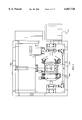
- FIG. 1 is a front elevation of the supercritical fluid dryer, showing the adjacent water heater/cooler, the control panel, the valve assembly, the pressure vessel in the closed position, and the clamping mechanism in the open position.
- FIG. 2 is a right side elevation of the supercritical fluid dryer of FIG. 1, with the pressure vessel cover shown in phantom in the open position.
- FIG. 3 is a rear elevation of the supercritical fluid dryer of FIG. 1, showing compressed air and CO 2 inlets.
- FIG. 4 is a top view of the supercritical fluid dryer of FIG. 1, illustrating the layout of the principal components of the clamping mechanism in the open position surrounding the pressure vessel.
- FIG. 5 is a top view of the chamber of the pressure vessel of FIG. 1, showing the lower interior of the cavity of the pressure vessel with a fluid distribution ring about the circumference.
- FIG. 6 is a top view of the fluid distribution ring with variable diameter holes, as is shown within the chamber of FIG. 5.
- FIG. 7 is a front view of the fluid distribution ring of FIG. 6.
- FIG. 8 is a left side elevation of the fluid distribution ring of FIG. 6.
- FIG. 9 is a side elevation of the chamber of FIG. 5.
- FIG. 10 is a rear elevation of the chamber of FIG. 5.
- FIG. 11 is the AA cross section view of the chamber of FIG. 10, revealing it's interior water channels.
- FIG. 12 is a bottom view of the chamber of FIGS. 5, 9 and 10, showing the ports to it's water channels and to the interior cavity of the pressure vessel, and the mounting holes for the lower roller plates.
- FIG. 13 is a top view of the cover of the pressure vessel of FIG. 1, showing the ports to it's water channels and the mounting holes for the upper roller wedges.
- FIG. 14 is a left side elevation of the cover of FIG. 13.
- FIG. 15 a front elevation of the cover of FIG. 13.
- FIG. 16 is the AA section view of the cover of FIG. 14, revealing it's interior water channels.
- FIG. 17 is a bottom view of the cover of FIG. 13, showing the upper surface of the closed cavity of the pressure vessel of FIG. 1.
- FIG. 18 is a front elevation of the left side clamp half locking ring of the clamping assembly of FIGS. 1 and 4.
- FIG. 19 is a bottom view of the left side clamp half locking ring of FIG. 18, showing the mounting holes for the rail guides.
- FIG. 20 is a top view of the left side clamp half locking ring of FIG. 18, showing the mounting holes for the top plate.
- FIG. 21 is an AA sectional view of the locking ring of FIG. 18.
- FIG. 22 is a BB sectional view of the locking ring of FIG. 18.
- FIG. 23 is a right side elevation of the locking ring of FIG. 18.
- FIG. 24 is a top view of the clamping mechanism of FIG. 4.
- FIG. 25 is the AA sectional view of FIG. 24, showing details of the clamping mechanism.
- FIG. 26 is the BB sectional view of FIG. 25, showing the right side spindle drive gearbox.
- FIG. 27 is the CC sectional view of FIG. 25, showing the left side spindle drive gearbox.
- FIG. 28 is a top view of the valve assembly of FIG. 1, showing the mechanical layout of the CO 2 plumbing.
- FIG. 29 is front elevation of the valve assembly of FIG. 28.
- FIG. 30 is a schematic diagram of CO2 and compressed air systems of the supercritical fluid dryer.
- FIG. 31 is a schematic of the water circulation system of the preferred embodiment.
- the principal components consist of a water heater/cooler 100 positioned closely to table frame 200, which supports valve assembly 300, pressure vessel 400, clamping mechanism 500 and control panel 600.
- the dryer requires the following inputs: a standard single phase, 115 volt, 40 ampere electrical supply, 0.5 SCFM (standard cubic feet per minute of compressed air at 60-80 PSIG, and 0.01 cu. ft. (liquid volume) of CO 2 at 1200 PSIG.
- Table frame is configured with retractable castors 202, and hood 204.
- Hood 204 has a transparent viewing panel 206 on the front side, and a blowout panel 208 on the back side.
- compressed air manual shutoff valve 331, inline filter 332, pressure regulator 333, and pressure gauge 334 are also shown. Also shown are CO 2 supply inlet 301, CO 2 process outlet 315, CO 2 vent outlet 320, and safety valve outlet 321.
- FIGS. 5-12 chamber 420 of pressure vessel 400 of FIG. 1 is depicted from several views.
- FIGS. 5, 9 and 10 clearly disclose mating surface 421 within which is centered chamber cavity 422, a shallow recess sufficiently large to accept a silicon wafer with supports.
- O-ring grove 423 in mating surface 421 accepts an O-ring seal for sealing the chamber to cover 440 (FIGS. 13-17).
- the fluid distribution ring structure creates by its profile, outer circumfrential channels connected by small lateral channels 701 and 703 to the chamber cavity 422. Opposing areas 702, generally coinciding with fluid inlet and outlet ports (ref. FIG. 12., ports 431 and 432), are blocked off or void of such channels.
- cooling channels 424 are bored into the chamber from two sides, the entrance holes being then plugged.
- Two cooling channel ports 425 through the bottom of chamber 420 into the channels provide inlet and outlet for heating/cooling water provided from water heater/cooler 100.
- thermocouple bore 426 accepts a type T thermocouple 436 to provide temperature data on chamber 420.
- Carbon Dioxide (CO 2 ) inlet port 431 and CO 2 outlet port 432 access cavity 422 through the bottom of chamber 420.
- the four sets of three hole patterns of support flange screw holes 435 are provided for mounting support flanges.
- Eight sets of three hole patterns of bottom roller plate screw holes 433 are provided for attach points for eight bottom roller plates 434 (not shown in this view).
- the cover 440 of pressure vessel 400 is the same overall diameter as chamber 420 of FIGS. 5-12.
- Mating flange 441 transitions by tapered shoulder 443 to interior surface 442. This surface forms the top of cavity 422 of chamber 420 when the cover is placed on the chamber.
- Cover 440 has lift assembly attach point 450 centered on it's top side, and is configured with internal cooling channels 444 and cooling channel ports 445, similar to the corresponding features of chamber 420.
- Eight sets of three hole patterns of locking wedge screw holes 453 are provided as mounting points for locking wedges 454 (not shown in this view).
- FIGS. 18-25 generally, and 18-23 specifically, the left clamp half locking ring 520 of clamping mechanism 500 is depicted from several perspectives.
- face surface 521 intersects at opposing edges with bottom surface 522 and top surface 523.
- FIGS. 21 and 22 show the stepped arrangement of the four upper and four lower cam follower roller mounting surfaces 524A and 524B respectively.
- Cam follower roller mounting surfaces 524A and 524B have cam follower roller mounting holes 538 through which cam follower roller attach bolts 525 are used to attach cam follower rollers 526.
- Upper and lower cam follower roller mounting surfaces 524A and 524B are separated by semi circular interior surface 539, which accommodates and conforms generally to the circular shape and height of one side of closed pressure vessel 400.
- Top surface 523 has several safety plate screw holes 537.
- Bottom surface 522 has four hole pattern linear bearing screw holes 527 for linear bearings 528 (not shown in this view).
- Back surface 540 has ball screw attach point 529 from which left clamp half locking ring 520 is pushed and pulled between the open and clamping positions of clamping mechanism 500.
- FIGS. 24-27 the layout of clamping mechanism 500, with it's attendant components is illustrated in detail.
- FIGS. 22 and 23 show left and right clamp half locking rings 520 and 550 in the open position, with cover 440 of pressure vessel 400 in place on chamber 420.
- two parallel rails 501 are configured to extend left and right across the bed of table frame 200.
- Linear bearings 528 are mounted to the underside of clamp half locking rings 520 and 550, and slidingly engaged with rails 501.
- reversible and variable speed drive motor 454 is connected by shaft coupler 535 to drive train 532 which consists of several drive shaft elements 533 and two right angle drives 534, to transfer power to left and right side transmissions 531.
- Left and right side transmissions 531 are interlocked by the drive train and configured to advance and retract screws 530 attached to ball screw attach points 529 on the back surfaces 540 of respective left and right clamp half locking rings 520 and 550, thereby advancing and retracting the clamp half locking rings on rails 501 in a synchronous manner towards and away from each other between open and clamping positions.
- chamber 420 is configured with support flanges 437 on its lower surface and supported by support rods 438 secured to table frame 200.
- drive motor 536 is operable to cause advancement of clamp half locking rings to a clamping position around pressure vessel 400, causing left side and right side upper cam follower rollers 545A and 555A to contact respective locking wedges 454 on cover 440, and left side and right side lower cam follower rollers 545B and 555B to contact respective bottom roller plates 434 mounted to the bottom of chamber 420.
- Left and right side safety plates 541 and 551 are bolted to top surfaces 523 of respective left and right clamp half locking rings 520 and 550. The safety plates are cut out on their respective leading edges so that when advanced to a clamping position, there is clearance for cover lift assembly 460.
- Pneumatically actuated safety latch assemblies 542 are mounted to either end of left side safety plate 541.
- Corresponding latch pin assemblies 552 are mounted to either end of right side safety plate 552 on right clamping half locking ring 550.
- Latch assemblies 542 are further configured with latch cams 543 which are engagable with the latch pin assemblies 552 when the clamp half locking rings are advanced to a clamping position.
- Latch pin assemblies 552 are further configured with plunger actuated pneumatic valves 553, such that the proper engagement of latch cams 543 with respective pin assemblies 552 operates their plunger actuated pneumatic valves 553.
- cover lift assembly 460 consists of cover lift arm 461, pivotally connected at one end to cover 440, and at it's other end to stanchion 462, which in turn is secured to table frame 200.
- Lift arm pneumatic cylinder is pivotally attached at one end to table frame 200 and at it's other end to a midpoint on cover lift arm 461, such that full extension of pneumatic cylinder 463 positions cover 440 on chamber 420, and full compression lifts cover 440 to the dotted line position of FIG. 2.
- valve assembly 300 with it's associated parts is illustrated.
- CO 2 supply inlet 301 (shown on FIG. 3) is connected serially by high pressure tubing to CO 2 inline filter 302, pneumatically actuated normally closed CO 2 supply shutoff valve 304, stepper motor operated CO 2 metering valve 305, metered CO 2 pressure gauge 306, metered CO 2 pressure transducer 307, and hence through CO 2 inlet 431 into cavity 422 of chamber 420 (shown on FIGS. 11 and 12).
- a back flow check valve is incorporated at inlet 431.
- Cavity 422 (of FIGS. 11 and 12) is further connected via CO 2 outlet 432 serially by high pressure tubing to CO 2 chamber outlet Tee 311, over pressure safety valve 312, manually operated CO 2 outlet valve 313, pneumatically actuated normally open CO 2 outlet shutoff valve 314, and hence to CO 2 process outlet 315 (shown on FIG. 3).
- An adjustable heat jacket 316 covers outlet valve 313 and shutoff valve 314.
- CO 2 chamber outlet Tee 311 is further serially connected by high pressure tubing to pneumatically actuated normally open CO 2 vent line shutoff valve 317, manually operated CO 2 vent line metering valve 318, and hence to vent outlet 320 (shown on FIG. 3).
- Safety valve 312 is further connected to safety valve outlet 321 (shown on FIG. 3).
- the compressed air system of the dryer consists of components connected by pressure tubing as follows: inlet 330 (FIG. 3) to manual shutoff valve 331, to inline filter 332, to pressure regulator 333, the pressure regulator thus providing regulated air to pressure switch 334, to lift arm closing solenoid valve 335 and hence to pneumatic cylinder 463. Regulated air is likewise provided to lift arm opening solenoid valve 336 and hence to the other end of pneumatic cylinder 463. Regulated air is likewise provided to safety latch solenoid valve 337, and hence to both ends of the pneumatic cylinders of safety latch assemblies 542.
- Regulated air is further supplied through serially connected plunger actuated pneumatic valves 553 of latch pin assemblies 552, to process section pressure switch 339, to CO 2 supply shutoff solenoid valve 340 and hence to shutoff valve 304, to CO 2 outlet shutoff solenoid valve 341 and hence to shutoff valve 314, and to CO 2 vent line shutoff solenoid valve 342 and hence to shutoff valve 317.
- Water heater/cooler 100 is able to heat or cool water as necessary to maintain a selected temperature range, and continuously pump water out outlet 101, to a 3-way solenoid preheat bypass valve 102, and switchable there from to either pressure side tee 103, hence in parallel to respective cooling channels of cover 440 and chamber 420, collecting return water to return side tee 104, passing through a second 3-way solenoid preheat bypass valve 105, and back to inlet 106.
- Bypass valves 102 and 105 are connected with a shunt line and operated together such that water is switchable to be passed through the cover and chamber, or bypassed through the shunt line.
- Type T thermocouple 436 mounted in the center of the underside of chamber 420, provides temperature feedback for the control function.
- control panel 900 integrates control of the various electrically controllable components with a keyboard/display and computer capability that provides manual control from the keyboard as well as programmable semi-automatic sequencing of the functions of the dryer.
- Common limit switches and pressure switches are electrically connected to the control panel are variously placed and adjusted to detect travel limits of moving components, or pressure levels, for control purposes in accordance with the overall process.
- the pressure vessel Prior to insertion of a wafer, the pressure vessel is filled with approximately 30 milliliters of methanol. A wafer is then placed onto a support structure while keeping a film of methanol on the wafer surface.
- the support structure allows an open space above and below the wafer for unobstructed flow.
- the process is then started by pressing the start button on the control panel.
- the control panel display will prompt the operator for any necessary intervention and provide a readout of process status during the cycle.
- the cycle commences with the chamber cover being lowered by a pneumatic cylinder and locking clamps being driven into position by an electric motor and gear train. This forces cam follower rollers on the clamps to contact tapered locking wedges on the cover, compressing the cover to the vessel o-ring seal and creating a sealed and locked assembly.
- An electrical limit switch controls the clamp position.
- two safety latches located on top of one of the clamps are pneumatically actuated to provide additional resistance to an undesired opening due to process pressure.
- These latches when brought into position latch onto mounted pins located on the other clamp and contact two plunger actuated pneumatic valves which in turn allow air pressure to a bank of solenoid valves.
- the solenoid valves in turn operate the CO 2 inlet, dilution and vent shutoff valves making for a fail safe system because the vessel cannot be pressurized unless the clamps are closed and the safety latches are locked.
- the CO 2 inlet valve opens and begins pressurizing the vessel.
- the distribution ring in the chamber cavity inhibits turbulence and promotes a laminar flow of CO 2 around the subject wafer.
- the flow rate is controlled by the motor positioning metering valve. It is important to pressurize the vessel slowly to avoid turbulence on the product.
- a transducer mounted in the inlet line senses pressure and provides a signal to the control panel for set point comparisons.
- the dilution shutoff valve opens and the CO 2 /methanol mixture begins to dilute out.
- a manually controlled metering valve regulates the outlet flow to avoid turbulence in the vessel while the inlet metering valve is opened further to assure enough pressure to keep the CO 2 in a liquid state (900 psi minimum).
- the dilution mode is controlled by a timed set point (approximately 8 minutes for this embodiment). At this point the PLC checks for a minimum pressure of 1100 psi and if found to be lower closes only the outlet shutoff valve while leaving the inlet open. When the set point is satisfied both valves will be closed and the heating mode will start.
- Both the vessel and the cover have channels machined into them for flowing water for temperature control.
- a packaged heater/chiller provides the means for pumping water through the channels and heating the CO 2 to 35-40 deg. Celsius.
- There is a thermocouple mounted in the vessel providing a signal to the control panel for set point comparisons. Preheated water is pumped through the system for approximately 10 minutes to achieve the temperature noted above. The pressure will undergo a corresponding rise of approximately 200 psi as the temperature increases and when the set point temperature is made a supercritical state has been reached.
- a vent circuit consisting of a shutoff and metering valve similar to the dilution circuit is also located on the outlet of the vessel.
- the shutoff valve opens and performs a controlled vent of the system. This takes approximately five minutes during which time the chiller brings the water temperature back under 30 degrees Celsius.
- the invention includes an apparatus for drying a microelectronic structure on wafer substrate, which has a pressure vessel with a lid and a base with an open cavity or bowl or depression formed in its top surface that is of uniform diameter and constant depth sufficient to contain at least one microelectronic structure on wafer substrate. A deeper cavity will hold several wafers in a stacked arrangement.
- the lid being emplaced on the base closes the cavity.
- the invention includes a mechanism for placing the lid on the base, such as a pneumatically actuated cylinder that raises and lowers the lid, and has a way for clamping the lid to the base by using at least two locking clamp rings, each having an open jaw sufficiently large to partially enclose the edge of the vessel.
- a mechanism for placing the lid on the base such as a pneumatically actuated cylinder that raises and lowers the lid, and has a way for clamping the lid to the base by using at least two locking clamp rings, each having an open jaw sufficiently large to partially enclose the edge of the vessel.
- the base of the vessel may be supported on stanchions on a base assembly and the lid operated by a swinging arm mechanism also attached to the base.
- the rings are supported symmetrically about the circumference of the vessel and oriented with the jaws facing the vessel.
- the rings are individually adjusted, or collectively movable by a common drive mechanism, between an open position where the rings are clear of the vessel and a locking position where the jaws partially enclose the vessel.
- the jaws and the vessel share a tapered cam plate and roller system configured to bring the rings into vertically compressive locking engagement on the pressure vessel when the rings are moved into locking position.
- the invention includes the necessary mechanisms and systems for controlling pressure in the cavity, for controlling temperature in the cavity, for flowing process fluid through the cavity, for venting the cavity, for unclamping the pressure vessel, and for removing the lid from the base.
- the invention may use two locking clamp rings, with the jaws configured with internal upper and lower rollers, and the vessel configured with top and bottom tapered cam plates, where the rollers are configured to contact respective cam plates when the rings are moved into locking position, bringing the rings into vertically compressive locking engagement on the pressure vessel.
- the invention includes an apparatus that has a control panel and control circuits for automatic operation according to a pre-determined sequence of process steps and within manually selectable or pre-determined limits of temperature, pressure and time.
- the apparatus may have a computer and control panel interconnected with other systems on the device, where the computer is programmable or programmed with a predetermined process sequence, and may include pre-determined or programmable limits of temperature, pressure and time.
- the apparatus may have a way for rigidly interconnecting or interlocking the locking clamp rings when in the locking position, such as a latching system with mating components secured to respective locking clamp rings and aligned so as to be brought into connecting position when the rings are moved into locking position.
- a latching system with mating components secured to respective locking clamp rings and aligned so as to be brought into connecting position when the rings are moved into locking position.
- the invention includes a pressure vessel with a way of distributing the incoming flow of process fluid around the circumference of its cavity, such as a system of channels connecting an incoming port to a plurality of orifices arranged symmetrically about the circumference of the cavity.
- the invention includes an apparatus for use with a wafer substrate being fabricated of silicon material, where the process fluid is carbon dioxide, the temperature in the cavity can be raised and regulated at in excess of 30 degrees centigrade, and the pressure in the cavity can be raised and regulated at in excess of 1000 pounds per square inch over atmosphere.
- the process fluid is carbon dioxide
- the temperature in the cavity can be raised and regulated at in excess of 30 degrees centigrade
- the pressure in the cavity can be raised and regulated at in excess of 1000 pounds per square inch over atmosphere.
- the invention includes a method for drying a microelectronic structure on wafer substrate, including the steps of submerging a microelectronic structure on wafer substrate in methanol in a horizontally oriented cavity of uniform diameter and constant vertical depth in the base of a pressure vessel consisting of a base and a lid, placing the lid on the base, and clamping the lid to the base with two locking clamp rings.
- Each ring has an open jaw sufficiently large to partially enclose an edge of the vessel.
- the method may include the base of the vessel being supported on stanchions on a base assembly and the lid operated by a swinging arm mechanism also attached to the base.
- the rings may be slidingly mounted on a common rail system that may run underneath the base, with the rings positioned on opposite sides of the vessel and oriented with their jaws open towards the vessel.
- the method would include introducing a through flow of process fluid in the cavity at supercritical temperature and pressure, evacuating process fluid from the closed cavity, unclamping the lid from the base, removing the lid from the base, and removing the microelectronic structure on wafer substrate from the cavity.
- the method may be for a wafer substrate fabricated of silicon material, with the process fluid being carbon dioxide, the supercritical temperature being in excess of 30 degrees centigrade, the supercritical pressure being in excess of 1000 pounds per square inch over atmosphere, and further include the automatic controlling and sequencing of the other steps of the process.
- the first and last steps of loading and unloading the wafer from the cavity may be done either manually or by automated means.
- the process fluid inlet 431 of the chamber of FIG. 12 may be located in the chamber cover of FIGS. 13-17, so as to introduce the process fluid from above the methanol bath without turbulence, rather than up through the bath.
- the process fluid then displaces the methanol, which is exhausted through the lower outlet port 432.
- the distribution ring 700 of FIGS. 5-8, or a similar structure may likewise be configured in or incorporated with the cover, to disburse the incoming fluid uniformally and with minimal turbulence.
Abstract
Description
Claims (20)
Priority Applications (1)
| Application Number | Priority Date | Filing Date | Title |
|---|---|---|---|
| US09/023,290 US6067728A (en) | 1998-02-13 | 1998-02-13 | Supercritical phase wafer drying/cleaning system |
Applications Claiming Priority (1)
| Application Number | Priority Date | Filing Date | Title |
|---|---|---|---|
| US09/023,290 US6067728A (en) | 1998-02-13 | 1998-02-13 | Supercritical phase wafer drying/cleaning system |
Publications (1)
| Publication Number | Publication Date |
|---|---|
| US6067728A true US6067728A (en) | 2000-05-30 |
Family
ID=21814208
Family Applications (1)
| Application Number | Title | Priority Date | Filing Date |
|---|---|---|---|
| US09/023,290 Expired - Fee Related US6067728A (en) | 1998-02-13 | 1998-02-13 | Supercritical phase wafer drying/cleaning system |
Country Status (1)
| Country | Link |
|---|---|
| US (1) | US6067728A (en) |
Cited By (76)
| Publication number | Priority date | Publication date | Assignee | Title |
|---|---|---|---|---|
| US6161311A (en) * | 1998-07-10 | 2000-12-19 | Asm America, Inc. | System and method for reducing particles in epitaxial reactors |
| GB2352001A (en) * | 1999-06-12 | 2001-01-17 | Clayton Commercials Ltd | A remotely operated locking lid system |
| US6209221B1 (en) * | 1998-05-14 | 2001-04-03 | Asm International N.V. | Wafer rack provided with a gas distribution device |
| EP1106946A2 (en) * | 1999-12-06 | 2001-06-13 | Nippon Telegraph and Telephone Corporation | Supercritical drying method and supercritical drying apparatus |
| US6364953B1 (en) * | 1999-06-23 | 2002-04-02 | Kabushiki Kaisha Kobe Seiko Sho. | Method and apparatus for making aerogel film |
| US20020046707A1 (en) * | 2000-07-26 | 2002-04-25 | Biberger Maximilian A. | High pressure processing chamber for semiconductor substrate |
| US6398875B1 (en) * | 2001-06-27 | 2002-06-04 | International Business Machines Corporation | Process of drying semiconductor wafers using liquid or supercritical carbon dioxide |
| WO2002066176A1 (en) * | 2001-02-15 | 2002-08-29 | Micell Technologies, Inc. | Methods for cleaning microelectronic structures |
| US20020189543A1 (en) * | 2001-04-10 | 2002-12-19 | Biberger Maximilian A. | High pressure processing chamber for semiconductor substrate including flow enhancing features |
| US20030027085A1 (en) * | 1997-05-27 | 2003-02-06 | Mullee William H. | Removal of photoresist and photoresist residue from semiconductors using supercritical carbon dioxide process |
| US6554507B2 (en) * | 1998-09-09 | 2003-04-29 | Nippon Telegraph And Telephone Corporation | Pattern formation method and apparatus |
| US6562146B1 (en) * | 2001-02-15 | 2003-05-13 | Micell Technologies, Inc. | Processes for cleaning and drying microelectronic structures using liquid or supercritical carbon dioxide |
| US20030121535A1 (en) * | 1999-11-02 | 2003-07-03 | Biberger Maximilian Albert | Method for supercritical processing of multiple workpieces |
| US6596093B2 (en) | 2001-02-15 | 2003-07-22 | Micell Technologies, Inc. | Methods for cleaning microelectronic structures with cyclical phase modulation |
| US6602351B2 (en) | 2001-02-15 | 2003-08-05 | Micell Technologies, Inc. | Methods for the control of contaminants following carbon dioxide cleaning of microelectronic structures |
| US20030150559A1 (en) * | 1999-11-02 | 2003-08-14 | Biberger Maximilian Albert | Apparatus for supercritical processing of a workpiece |
| US20030155541A1 (en) * | 2002-02-15 | 2003-08-21 | Supercritical Systems, Inc. | Pressure enhanced diaphragm valve |
| US6612317B2 (en) | 2000-04-18 | 2003-09-02 | S.C. Fluids, Inc | Supercritical fluid delivery and recovery system for semiconductor wafer processing |
| US6613157B2 (en) | 2001-02-15 | 2003-09-02 | Micell Technologies, Inc. | Methods for removing particles from microelectronic structures |
| US6619304B2 (en) | 2001-09-13 | 2003-09-16 | Micell Technologies, Inc. | Pressure chamber assembly including non-mechanical drive means |
| US6641678B2 (en) | 2001-02-15 | 2003-11-04 | Micell Technologies, Inc. | Methods for cleaning microelectronic structures with aqueous carbon dioxide systems |
| EP1358021A1 (en) * | 2000-08-04 | 2003-11-05 | S. C. Fluids, Inc. | Inverted pressure vessel with shielded closure mechanism |
| US6656666B2 (en) * | 2000-12-22 | 2003-12-02 | International Business Machines Corporation | Topcoat process to prevent image collapse |
| US20030232512A1 (en) * | 2002-06-13 | 2003-12-18 | Dickinson C. John | Substrate processing apparatus and related systems and methods |
| US6666928B2 (en) | 2001-09-13 | 2003-12-23 | Micell Technologies, Inc. | Methods and apparatus for holding a substrate in a pressure chamber |
| US6678968B1 (en) | 2000-05-25 | 2004-01-20 | Tousimis Research Corporation | Supercritical point drying apparatus for semiconductor device manufacturing and bio-medical sample processing |
| US20040025908A1 (en) * | 2000-04-18 | 2004-02-12 | Stephen Douglas | Supercritical fluid delivery system for semiconductor wafer processing |
| US20040040660A1 (en) * | 2001-10-03 | 2004-03-04 | Biberger Maximilian Albert | High pressure processing chamber for multiple semiconductor substrates |
| US6706641B2 (en) | 2001-09-13 | 2004-03-16 | Micell Technologies, Inc. | Spray member and method for using the same |
| US6722642B1 (en) | 2002-11-06 | 2004-04-20 | Tokyo Electron Limited | High pressure compatible vacuum chuck for semiconductor wafer including lift mechanism |
| US20040094183A1 (en) * | 2002-11-18 | 2004-05-20 | Recif, Societe Anonyme | Substrate processing apparatus for processing substrates using dense phase gas and sonic waves |
| US20040118430A1 (en) * | 2001-12-28 | 2004-06-24 | Hansen Brian Nils | Pressure processing apparatus with improved heating and closure system |
| US6763840B2 (en) | 2001-09-14 | 2004-07-20 | Micell Technologies, Inc. | Method and apparatus for cleaning substrates using liquid carbon dioxide |
| US20040139987A1 (en) * | 2003-01-13 | 2004-07-22 | Mount David J. | Method for releasing and drying moveable elements of micro-electronic mechanical structures with organic thin film sacrificial layers |
| US20040139986A1 (en) * | 2003-01-10 | 2004-07-22 | Mount David J. | Adding energy to a cleaning process fluid for removing photo resist, residues and particles from semiconductor substrates, photo masks, reticles, disks and flat-panel displays |
| US20040154647A1 (en) * | 2003-02-07 | 2004-08-12 | Supercritical Systems, Inc. | Method and apparatus of utilizing a coating for enhanced holding of a semiconductor substrate during high pressure processing |
| US6782900B2 (en) | 2001-09-13 | 2004-08-31 | Micell Technologies, Inc. | Methods and apparatus for cleaning and/or treating a substrate using CO2 |
| US20040187894A1 (en) * | 2003-03-31 | 2004-09-30 | Lam Research Corporation | Wafer clamping apparatus and method for operating the same |
| US20040211447A1 (en) * | 2003-04-28 | 2004-10-28 | Supercritical Systems, Inc. | Apparatus and method of securing a workpiece during high-pressure processing |
| US20050008980A1 (en) * | 2002-02-15 | 2005-01-13 | Arena-Foster Chantal J. | Developing photoresist with supercritical fluid and developer |
| EP1503401A1 (en) * | 2003-08-01 | 2005-02-02 | Vlaamse Instelling Voor Technologisch Onderzoek (Vito) | Method and apparatus for cleaning a substrate by using a supercritical fluid |
| US20050028927A1 (en) * | 2003-08-06 | 2005-02-10 | Cem Basceri | Supercritical fluid technology for cleaning processing chambers and systems |
| US20050034660A1 (en) * | 2003-08-11 | 2005-02-17 | Supercritical Systems, Inc. | Alignment means for chamber closure to reduce wear on surfaces |
| US6905555B2 (en) | 2001-02-15 | 2005-06-14 | Micell Technologies, Inc. | Methods for transferring supercritical fluids in microelectronic and other industrial processes |
| US20050164127A1 (en) * | 2001-06-15 | 2005-07-28 | Reid Jason S. | Method for removing a sacrificial material with a compressed fluid |
| US20050191861A1 (en) * | 2003-03-21 | 2005-09-01 | Steven Verhaverbeke | Using supercritical fluids and/or dense fluids in semiconductor applications |
| US6953654B2 (en) | 2002-03-14 | 2005-10-11 | Tokyo Electron Limited | Process and apparatus for removing a contaminant from a substrate |
| US20050279453A1 (en) * | 2004-06-17 | 2005-12-22 | Uvtech Systems, Inc. | System and methods for surface cleaning |
| DE10255231B4 (en) * | 2002-11-26 | 2006-02-02 | Uhde High Pressure Technologies Gmbh | High pressure device for closing a pressure vessel in the clean room |
| US20060135047A1 (en) * | 2004-12-22 | 2006-06-22 | Alexei Sheydayi | Method and apparatus for clamping a substrate in a high pressure processing system |
| US20060130913A1 (en) * | 2004-12-22 | 2006-06-22 | Alexei Sheydayi | Non-contact shuttle valve for flow diversion in high pressure systems |
| US20060130875A1 (en) * | 2004-12-22 | 2006-06-22 | Alexei Sheydayi | Method and apparatus for clamping a substrate in a high pressure processing system |
| US20060130477A1 (en) * | 2002-11-26 | 2006-06-22 | Uhde High Pressure Technologies Gmbh | High pressure device and method for clean room applications |
| US20060130966A1 (en) * | 2004-12-20 | 2006-06-22 | Darko Babic | Method and system for flowing a supercritical fluid in a high pressure processing system |
| US20060180175A1 (en) * | 2005-02-15 | 2006-08-17 | Parent Wayne M | Method and system for determining flow conditions in a high pressure processing system |
| US20060266287A1 (en) * | 2005-05-25 | 2006-11-30 | Parent Wayne M | Method and system for passivating a processing chamber |
| US20070158654A1 (en) * | 2006-01-03 | 2007-07-12 | Kholodenko Arnold V | Apparatus for fabricating large-surface area polycrystalline silicon sheets for solar cell application |
| US20070169791A1 (en) * | 2006-01-21 | 2007-07-26 | Industry-University Cooperation Foundation Sogang University | Cleaning process |
| US20070169373A1 (en) * | 2006-01-25 | 2007-07-26 | Tokyo Electron Limited | Heat processing apparatus and heat processing method |
| US20080060214A1 (en) * | 2006-09-07 | 2008-03-13 | Hideki Nishimura | Substrate processing method, substrate processing apparatus, and program storage medium |
| US20080264443A1 (en) * | 2002-02-05 | 2008-10-30 | Novellus Systems, Inc. | Apparatus and methods for increasing the rate of solute concentration evolution in a supercritical process chamber |
| US7503334B1 (en) | 2002-02-05 | 2009-03-17 | Novellus Systems, Inc. | Apparatus and methods for processing semiconductor substrates using supercritical fluids |
| US7767145B2 (en) | 2005-03-28 | 2010-08-03 | Toyko Electron Limited | High pressure fourier transform infrared cell |
| US7789971B2 (en) | 2005-05-13 | 2010-09-07 | Tokyo Electron Limited | Treatment of substrate using functionalizing agent in supercritical carbon dioxide |
| US7797855B2 (en) * | 2005-08-31 | 2010-09-21 | Tokyo Electron Limited | Heating apparatus, and coating and developing apparatus |
| US20110143553A1 (en) * | 2009-12-11 | 2011-06-16 | Lam Research Corporation | Integrated tool sets and process to keep substrate surface wet during plating and clean in fabrication of advanced nano-electronic devices |
| CN102160149A (en) * | 2008-09-24 | 2011-08-17 | 朗姆研究公司 | Methods and systems for preventing feature collapse during microelectronic topography fabrication |
| US20130145640A1 (en) * | 2011-12-07 | 2013-06-13 | Samsung Electronics Co., Ltd. | Apparatus and methods for treating a substrate |
| CN103569672A (en) * | 2012-07-20 | 2014-02-12 | 上海微电子装备有限公司 | Silicon wafer and glass substrate compatible conveying device |
| US20170256397A1 (en) * | 2016-03-02 | 2017-09-07 | Tokyo Electron Limited | Substrate processing apparatus, substrate processing method, and storage medium |
| US20180114707A1 (en) * | 2016-10-26 | 2018-04-26 | Semes Co., Ltd. | Apparatus and method for treating substrate |
| US20180264504A1 (en) * | 2017-03-14 | 2018-09-20 | Tokyo Electron Limited | Substrate processing apparatus and substrate processing method |
| US10096462B2 (en) | 2012-07-18 | 2018-10-09 | Toshiba Memory Corporation | Substrate processing method and storage medium |
| CN104380438B (en) * | 2012-04-17 | 2018-11-06 | 普莱克斯技术有限公司 | The system for being delivered to handling implement for multiphase carbon dioxide will to be purified |
| US10395950B2 (en) * | 2016-11-04 | 2019-08-27 | Tokyo Electron Limited | Substrate processing apparatus, substrate processing method, and recording medium |
| CN110950020A (en) * | 2019-10-25 | 2020-04-03 | 深圳市拉普拉斯能源技术有限公司 | Boat turning device |
-
1998
- 1998-02-13 US US09/023,290 patent/US6067728A/en not_active Expired - Fee Related
Non-Patent Citations (6)
| Title |
|---|
| Dai Kobayashi et al, Photoresist Assisted Release of Movable Microstructures , vol. 32, 1993, pp. L1642 L1644, Jpn. J. Appl. Phys. * |
| Dai Kobayashi et al, Photoresist-Assisted Release of Movable Microstructures, vol. 32, 1993, pp. L1642-L1644, Jpn. J. Appl. Phys. |
| Gregory T. Mulhern et al, Supercritical Carbon Dioxide Drying of Microstructures , pp. 296 300., Seventh International Conference on Solid State Sensors & Actuators; Yokohama, Japan, 1993. * |
| Gregory T. Mulhern et al, Supercritical Carbon Dioxide Drying of Microstructures, pp. 296-300., Seventh International Conference on Solid-State Sensors & Actuators; Yokohama, Japan, 1993. |
| John Y. Kim et al, Comparative Study of Various Release Methods For Polysilicon Surface Micromachining , Jan. 1997, Nagoya, Japan, pp. 442 447. * |
| John Y. Kim et al, Comparative Study of Various Release Methods For Polysilicon Surface Micromachining, Jan. 1997, Nagoya, Japan, pp. 442-447. |
Cited By (119)
| Publication number | Priority date | Publication date | Assignee | Title |
|---|---|---|---|---|
| US20030027085A1 (en) * | 1997-05-27 | 2003-02-06 | Mullee William H. | Removal of photoresist and photoresist residue from semiconductors using supercritical carbon dioxide process |
| US6209221B1 (en) * | 1998-05-14 | 2001-04-03 | Asm International N.V. | Wafer rack provided with a gas distribution device |
| US6161311A (en) * | 1998-07-10 | 2000-12-19 | Asm America, Inc. | System and method for reducing particles in epitaxial reactors |
| US6550158B2 (en) | 1998-07-10 | 2003-04-22 | Asm America, Inc. | Substrate handling chamber |
| US6554507B2 (en) * | 1998-09-09 | 2003-04-29 | Nippon Telegraph And Telephone Corporation | Pattern formation method and apparatus |
| GB2352001A (en) * | 1999-06-12 | 2001-01-17 | Clayton Commercials Ltd | A remotely operated locking lid system |
| US6364953B1 (en) * | 1999-06-23 | 2002-04-02 | Kabushiki Kaisha Kobe Seiko Sho. | Method and apparatus for making aerogel film |
| US20030150559A1 (en) * | 1999-11-02 | 2003-08-14 | Biberger Maximilian Albert | Apparatus for supercritical processing of a workpiece |
| US6736149B2 (en) | 1999-11-02 | 2004-05-18 | Supercritical Systems, Inc. | Method and apparatus for supercritical processing of multiple workpieces |
| US6748960B1 (en) | 1999-11-02 | 2004-06-15 | Tokyo Electron Limited | Apparatus for supercritical processing of multiple workpieces |
| US20030121535A1 (en) * | 1999-11-02 | 2003-07-03 | Biberger Maximilian Albert | Method for supercritical processing of multiple workpieces |
| US6576066B1 (en) | 1999-12-06 | 2003-06-10 | Nippon Telegraph And Telephone Corporation | Supercritical drying method and supercritical drying apparatus |
| EP1106946A3 (en) * | 1999-12-06 | 2002-04-10 | Nippon Telegraph and Telephone Corporation | Supercritical drying method and supercritical drying apparatus |
| EP1106946A2 (en) * | 1999-12-06 | 2001-06-13 | Nippon Telegraph and Telephone Corporation | Supercritical drying method and supercritical drying apparatus |
| US6612317B2 (en) | 2000-04-18 | 2003-09-02 | S.C. Fluids, Inc | Supercritical fluid delivery and recovery system for semiconductor wafer processing |
| US20040025908A1 (en) * | 2000-04-18 | 2004-02-12 | Stephen Douglas | Supercritical fluid delivery system for semiconductor wafer processing |
| US6857200B1 (en) * | 2000-05-25 | 2005-02-22 | Tousimis Research Corporation | Supercritical point drying apparatus for semiconductor device manufacturing and bio-medical sample processing |
| US6883674B1 (en) | 2000-05-25 | 2005-04-26 | Tousimis Research Corporation | Holder for use in semiconductor device manufacturing and bio-medical sample processing |
| US6678968B1 (en) | 2000-05-25 | 2004-01-20 | Tousimis Research Corporation | Supercritical point drying apparatus for semiconductor device manufacturing and bio-medical sample processing |
| US20050000651A1 (en) * | 2000-07-26 | 2005-01-06 | Biberger Maximilian A. | High pressure processing chamber for semiconductor substrate |
| US20020046707A1 (en) * | 2000-07-26 | 2002-04-25 | Biberger Maximilian A. | High pressure processing chamber for semiconductor substrate |
| US6921456B2 (en) * | 2000-07-26 | 2005-07-26 | Tokyo Electron Limited | High pressure processing chamber for semiconductor substrate |
| EP1358021A4 (en) * | 2000-08-04 | 2004-03-31 | S C Fluids Inc | Inverted pressure vessel with shielded closure mechanism |
| EP1358021A1 (en) * | 2000-08-04 | 2003-11-05 | S. C. Fluids, Inc. | Inverted pressure vessel with shielded closure mechanism |
| US6656666B2 (en) * | 2000-12-22 | 2003-12-02 | International Business Machines Corporation | Topcoat process to prevent image collapse |
| US6905555B2 (en) | 2001-02-15 | 2005-06-14 | Micell Technologies, Inc. | Methods for transferring supercritical fluids in microelectronic and other industrial processes |
| US6596093B2 (en) | 2001-02-15 | 2003-07-22 | Micell Technologies, Inc. | Methods for cleaning microelectronic structures with cyclical phase modulation |
| WO2002066176A1 (en) * | 2001-02-15 | 2002-08-29 | Micell Technologies, Inc. | Methods for cleaning microelectronic structures |
| US6641678B2 (en) | 2001-02-15 | 2003-11-04 | Micell Technologies, Inc. | Methods for cleaning microelectronic structures with aqueous carbon dioxide systems |
| US6562146B1 (en) * | 2001-02-15 | 2003-05-13 | Micell Technologies, Inc. | Processes for cleaning and drying microelectronic structures using liquid or supercritical carbon dioxide |
| US6602351B2 (en) | 2001-02-15 | 2003-08-05 | Micell Technologies, Inc. | Methods for the control of contaminants following carbon dioxide cleaning of microelectronic structures |
| US6613157B2 (en) | 2001-02-15 | 2003-09-02 | Micell Technologies, Inc. | Methods for removing particles from microelectronic structures |
| US20020189543A1 (en) * | 2001-04-10 | 2002-12-19 | Biberger Maximilian A. | High pressure processing chamber for semiconductor substrate including flow enhancing features |
| US6958123B2 (en) | 2001-06-15 | 2005-10-25 | Reflectivity, Inc | Method for removing a sacrificial material with a compressed fluid |
| US20050164127A1 (en) * | 2001-06-15 | 2005-07-28 | Reid Jason S. | Method for removing a sacrificial material with a compressed fluid |
| US6398875B1 (en) * | 2001-06-27 | 2002-06-04 | International Business Machines Corporation | Process of drying semiconductor wafers using liquid or supercritical carbon dioxide |
| US6782900B2 (en) | 2001-09-13 | 2004-08-31 | Micell Technologies, Inc. | Methods and apparatus for cleaning and/or treating a substrate using CO2 |
| US6730612B2 (en) | 2001-09-13 | 2004-05-04 | Micell Technologies, Inc. | Spray member and method for using the same |
| US6619304B2 (en) | 2001-09-13 | 2003-09-16 | Micell Technologies, Inc. | Pressure chamber assembly including non-mechanical drive means |
| US6666928B2 (en) | 2001-09-13 | 2003-12-23 | Micell Technologies, Inc. | Methods and apparatus for holding a substrate in a pressure chamber |
| US6706641B2 (en) | 2001-09-13 | 2004-03-16 | Micell Technologies, Inc. | Spray member and method for using the same |
| US6763840B2 (en) | 2001-09-14 | 2004-07-20 | Micell Technologies, Inc. | Method and apparatus for cleaning substrates using liquid carbon dioxide |
| US20040040660A1 (en) * | 2001-10-03 | 2004-03-04 | Biberger Maximilian Albert | High pressure processing chamber for multiple semiconductor substrates |
| US7028698B2 (en) * | 2001-12-28 | 2006-04-18 | Brian Nils Hansen | Pressure processing apparatus with improved heating and closure system |
| US20040118430A1 (en) * | 2001-12-28 | 2004-06-24 | Hansen Brian Nils | Pressure processing apparatus with improved heating and closure system |
| US20080264443A1 (en) * | 2002-02-05 | 2008-10-30 | Novellus Systems, Inc. | Apparatus and methods for increasing the rate of solute concentration evolution in a supercritical process chamber |
| US7503334B1 (en) | 2002-02-05 | 2009-03-17 | Novellus Systems, Inc. | Apparatus and methods for processing semiconductor substrates using supercritical fluids |
| US20030155541A1 (en) * | 2002-02-15 | 2003-08-21 | Supercritical Systems, Inc. | Pressure enhanced diaphragm valve |
| US20050008980A1 (en) * | 2002-02-15 | 2005-01-13 | Arena-Foster Chantal J. | Developing photoresist with supercritical fluid and developer |
| US6953654B2 (en) | 2002-03-14 | 2005-10-11 | Tokyo Electron Limited | Process and apparatus for removing a contaminant from a substrate |
| US6846380B2 (en) | 2002-06-13 | 2005-01-25 | The Boc Group, Inc. | Substrate processing apparatus and related systems and methods |
| US20030232512A1 (en) * | 2002-06-13 | 2003-12-18 | Dickinson C. John | Substrate processing apparatus and related systems and methods |
| US6722642B1 (en) | 2002-11-06 | 2004-04-20 | Tokyo Electron Limited | High pressure compatible vacuum chuck for semiconductor wafer including lift mechanism |
| US6880560B2 (en) | 2002-11-18 | 2005-04-19 | Techsonic | Substrate processing apparatus for processing substrates using dense phase gas and sonic waves |
| US20040094183A1 (en) * | 2002-11-18 | 2004-05-20 | Recif, Societe Anonyme | Substrate processing apparatus for processing substrates using dense phase gas and sonic waves |
| US7275373B2 (en) | 2002-11-26 | 2007-10-02 | Uhde High Pressure Technologies Gmbh | High pressure device and method for clean room applications |
| US20070037399A1 (en) * | 2002-11-26 | 2007-02-15 | Christoph Luetge | High-pressure device for closing a container in a clean room |
| US20060130477A1 (en) * | 2002-11-26 | 2006-06-22 | Uhde High Pressure Technologies Gmbh | High pressure device and method for clean room applications |
| DE10255231B4 (en) * | 2002-11-26 | 2006-02-02 | Uhde High Pressure Technologies Gmbh | High pressure device for closing a pressure vessel in the clean room |
| US20040139986A1 (en) * | 2003-01-10 | 2004-07-22 | Mount David J. | Adding energy to a cleaning process fluid for removing photo resist, residues and particles from semiconductor substrates, photo masks, reticles, disks and flat-panel displays |
| US6935352B2 (en) | 2003-01-10 | 2005-08-30 | S.C. Fluids, Inc. | Adding energy to a cleaning process fluid for removing photo resist, residues and particles from semiconductor substrates, photo masks, reticles, disks and flat-panel displays |
| WO2004064244A2 (en) * | 2003-01-13 | 2004-07-29 | S.C. Fluids Inc. | Method for releasing and drying moveable elements of micro-electronic mechanical structures with organic thin film sacrificial layers |
| US20040139987A1 (en) * | 2003-01-13 | 2004-07-22 | Mount David J. | Method for releasing and drying moveable elements of micro-electronic mechanical structures with organic thin film sacrificial layers |
| WO2004064244A3 (en) * | 2003-01-13 | 2004-11-25 | S C Fluids Inc | Method for releasing and drying moveable elements of micro-electronic mechanical structures with organic thin film sacrificial layers |
| US20040154647A1 (en) * | 2003-02-07 | 2004-08-12 | Supercritical Systems, Inc. | Method and apparatus of utilizing a coating for enhanced holding of a semiconductor substrate during high pressure processing |
| US20050191861A1 (en) * | 2003-03-21 | 2005-09-01 | Steven Verhaverbeke | Using supercritical fluids and/or dense fluids in semiconductor applications |
| US7357115B2 (en) * | 2003-03-31 | 2008-04-15 | Lam Research Corporation | Wafer clamping apparatus and method for operating the same |
| US20040187894A1 (en) * | 2003-03-31 | 2004-09-30 | Lam Research Corporation | Wafer clamping apparatus and method for operating the same |
| US20040211447A1 (en) * | 2003-04-28 | 2004-10-28 | Supercritical Systems, Inc. | Apparatus and method of securing a workpiece during high-pressure processing |
| EP1503401A1 (en) * | 2003-08-01 | 2005-02-02 | Vlaamse Instelling Voor Technologisch Onderzoek (Vito) | Method and apparatus for cleaning a substrate by using a supercritical fluid |
| US20050028927A1 (en) * | 2003-08-06 | 2005-02-10 | Cem Basceri | Supercritical fluid technology for cleaning processing chambers and systems |
| US20060070637A1 (en) * | 2003-08-06 | 2006-04-06 | Cem Basceri | Supercritical fluid technology for cleaning processing chambers and systems |
| US7323064B2 (en) | 2003-08-06 | 2008-01-29 | Micron Technology, Inc. | Supercritical fluid technology for cleaning processing chambers and systems |
| US20050034660A1 (en) * | 2003-08-11 | 2005-02-17 | Supercritical Systems, Inc. | Alignment means for chamber closure to reduce wear on surfaces |
| US7514015B2 (en) | 2004-06-17 | 2009-04-07 | Uvtech Systems | Method for surface cleaning |
| US20050279380A1 (en) * | 2004-06-17 | 2005-12-22 | Uvtech Systems, Inc. | Method for surface cleaning |
| US20050279453A1 (en) * | 2004-06-17 | 2005-12-22 | Uvtech Systems, Inc. | System and methods for surface cleaning |
| US20060231204A1 (en) * | 2004-06-17 | 2006-10-19 | Uvtech Systems, Inc. | Portable system for semiconductor manufacturing |
| US20060130966A1 (en) * | 2004-12-20 | 2006-06-22 | Darko Babic | Method and system for flowing a supercritical fluid in a high pressure processing system |
| US20060135047A1 (en) * | 2004-12-22 | 2006-06-22 | Alexei Sheydayi | Method and apparatus for clamping a substrate in a high pressure processing system |
| US20060130913A1 (en) * | 2004-12-22 | 2006-06-22 | Alexei Sheydayi | Non-contact shuttle valve for flow diversion in high pressure systems |
| US20060130875A1 (en) * | 2004-12-22 | 2006-06-22 | Alexei Sheydayi | Method and apparatus for clamping a substrate in a high pressure processing system |
| US20060180175A1 (en) * | 2005-02-15 | 2006-08-17 | Parent Wayne M | Method and system for determining flow conditions in a high pressure processing system |
| US7767145B2 (en) | 2005-03-28 | 2010-08-03 | Toyko Electron Limited | High pressure fourier transform infrared cell |
| US7789971B2 (en) | 2005-05-13 | 2010-09-07 | Tokyo Electron Limited | Treatment of substrate using functionalizing agent in supercritical carbon dioxide |
| US20060266287A1 (en) * | 2005-05-25 | 2006-11-30 | Parent Wayne M | Method and system for passivating a processing chamber |
| US7797855B2 (en) * | 2005-08-31 | 2010-09-21 | Tokyo Electron Limited | Heating apparatus, and coating and developing apparatus |
| US20070158654A1 (en) * | 2006-01-03 | 2007-07-12 | Kholodenko Arnold V | Apparatus for fabricating large-surface area polycrystalline silicon sheets for solar cell application |
| US7572334B2 (en) | 2006-01-03 | 2009-08-11 | Applied Materials, Inc. | Apparatus for fabricating large-surface area polycrystalline silicon sheets for solar cell application |
| US20070169791A1 (en) * | 2006-01-21 | 2007-07-26 | Industry-University Cooperation Foundation Sogang University | Cleaning process |
| US8080114B2 (en) * | 2006-01-21 | 2011-12-20 | Industry-University Cooperation Foundation Sogang University | Cleaning process |
| US20110236845A1 (en) * | 2006-01-25 | 2011-09-29 | Tokyo Electron Limited | Heat processing apparatus and heat processing method |
| US7980003B2 (en) * | 2006-01-25 | 2011-07-19 | Tokyo Electron Limited | Heat processing apparatus and heat processing method |
| US8782918B2 (en) | 2006-01-25 | 2014-07-22 | Tokyo Electron Limited | Heat processing apparatus and heat processing method |
| US20070169373A1 (en) * | 2006-01-25 | 2007-07-26 | Tokyo Electron Limited | Heat processing apparatus and heat processing method |
| US8020315B2 (en) * | 2006-09-07 | 2011-09-20 | Tokyo Electron Limited | Substrate processing method, substrate processing apparatus, and program storage medium |
| US20080060214A1 (en) * | 2006-09-07 | 2008-03-13 | Hideki Nishimura | Substrate processing method, substrate processing apparatus, and program storage medium |
| US8266820B2 (en) | 2006-09-07 | 2012-09-18 | Tokyo Electron Limited | Substrate processing method, and program storage medium therefor |
| CN102160149A (en) * | 2008-09-24 | 2011-08-17 | 朗姆研究公司 | Methods and systems for preventing feature collapse during microelectronic topography fabrication |
| CN102160149B (en) * | 2008-09-24 | 2014-09-17 | 朗姆研究公司 | Methods and systems for preventing feature collapse during microelectronic topography fabrication |
| US20110143553A1 (en) * | 2009-12-11 | 2011-06-16 | Lam Research Corporation | Integrated tool sets and process to keep substrate surface wet during plating and clean in fabrication of advanced nano-electronic devices |
| US20130145640A1 (en) * | 2011-12-07 | 2013-06-13 | Samsung Electronics Co., Ltd. | Apparatus and methods for treating a substrate |
| US9534839B2 (en) * | 2011-12-07 | 2017-01-03 | Samsung Electronics Co., Ltd. | Apparatus and methods for treating a substrate |
| US10361100B2 (en) | 2011-12-07 | 2019-07-23 | Samsung Electronics Co., Ltd. | Apparatus and methods for treating a substrate |
| CN104380438B (en) * | 2012-04-17 | 2018-11-06 | 普莱克斯技术有限公司 | The system for being delivered to handling implement for multiphase carbon dioxide will to be purified |
| US10096462B2 (en) | 2012-07-18 | 2018-10-09 | Toshiba Memory Corporation | Substrate processing method and storage medium |
| CN103569672B (en) * | 2012-07-20 | 2016-03-09 | 上海微电子装备有限公司 | The transmitting device of a kind of compatible silicon chip and glass substrate |
| CN103569672A (en) * | 2012-07-20 | 2014-02-12 | 上海微电子装备有限公司 | Silicon wafer and glass substrate compatible conveying device |
| US10566182B2 (en) * | 2016-03-02 | 2020-02-18 | Tokyo Electron Limited | Substrate processing apparatus, substrate processing method, and storage medium |
| US20170256397A1 (en) * | 2016-03-02 | 2017-09-07 | Tokyo Electron Limited | Substrate processing apparatus, substrate processing method, and storage medium |
| US10998186B2 (en) | 2016-03-02 | 2021-05-04 | Tokyo Electron Limited | Substrate processing apparatus, substrate processing method, and storage medium |
| CN107993959A (en) * | 2016-10-26 | 2018-05-04 | 细美事有限公司 | Apparatus and method for handling substrate |
| US20180114707A1 (en) * | 2016-10-26 | 2018-04-26 | Semes Co., Ltd. | Apparatus and method for treating substrate |
| US10529594B2 (en) * | 2016-10-26 | 2020-01-07 | Semes Co., Ltd. | Apparatus and method for treating substrate |
| CN107993959B (en) * | 2016-10-26 | 2022-01-28 | 细美事有限公司 | Apparatus and method for processing substrate |
| US10395950B2 (en) * | 2016-11-04 | 2019-08-27 | Tokyo Electron Limited | Substrate processing apparatus, substrate processing method, and recording medium |
| US20180264504A1 (en) * | 2017-03-14 | 2018-09-20 | Tokyo Electron Limited | Substrate processing apparatus and substrate processing method |
| US10576493B2 (en) * | 2017-03-14 | 2020-03-03 | Tokyo Electron Limited | Substrate processing apparatus and substrate processing method |
| CN110950020A (en) * | 2019-10-25 | 2020-04-03 | 深圳市拉普拉斯能源技术有限公司 | Boat turning device |
Similar Documents
| Publication | Publication Date | Title |
|---|---|---|
| US6067728A (en) | Supercritical phase wafer drying/cleaning system | |
| US6423947B2 (en) | Thermal processing chamber for heating and cooling wafer-like objects | |
| US6180060B1 (en) | Analyzer transport device | |
| DE69937042T2 (en) | COMBINATIONAL DEVICE FOR EPITACTIC MOLECULAR LAYER | |
| KR20030039247A (en) | Susceptor | |
| US6564474B2 (en) | Apparatus for heat processing of substrate | |
| EP0632760B1 (en) | Process for sealing compounds in an impregnating compound | |
| US5725835A (en) | Device for initiating and/or promoting chemical or physical processes in a material | |
| DE2218609A1 (en) | REACTOR SYSTEM FOR CREATING LAYERS ON A SUBSTRATE | |
| US4208372A (en) | Apparatus for generating and transferring a gaseous test sample to an atomic absorption spectrometer | |
| US5567381A (en) | Hybrid heat treating furnace | |
| US4890725A (en) | Automatic continuously cycleable molding system and method | |
| CN109765088B (en) | Semiconductor material preparation equipment | |
| KR20040103714A (en) | Apparatus for wafer loading, and the method | |
| US7028698B2 (en) | Pressure processing apparatus with improved heating and closure system | |
| DE2140756C3 (en) | Process and devices for the production of laminated safety glass by gluing panes during a heat overpressure treatment in an autoclave and subsequent liquid pressure cooling | |
| KR100585994B1 (en) | Treating Apparatus for Autoclave | |
| CN117038528A (en) | Substrate drying system and substrate drying method | |
| CN217377970U (en) | Heating device of heat treatment equipment | |
| CN215881558U (en) | Automatic rapid water detection clamp | |
| JPS5942678Y2 (en) | Liquid-liquid automatic extraction device | |
| RU2105822C1 (en) | Method for hardening of flat parts and device for its embodiment | |
| DE2732206A1 (en) | DEVICE FOR DYING YARN WITH A DRYING DEVICE | |
| EP1027933A1 (en) | Device and method for sample treatment | |
| JP3635476B2 (en) | Processed food manufacturing method and apparatus |
Legal Events
| Date | Code | Title | Description |
|---|---|---|---|
| AS | Assignment |
Owner name: GT EQUIPMENT TECHNOLOGIES INC., NEW HAMPSHIRE Free format text: ASSIGNMENT OF ASSIGNORS INTEREST;ASSIGNORS:FARMER, ROBERT B.;JONES, BERNARD D.;GUPTA, KEDAR P.;AND OTHERS;REEL/FRAME:008976/0015 Effective date: 19980204 |
|
| AS | Assignment |
Owner name: NHBDC VENTURE PARTNERS, L.P. ( A NEW HAMPSHIRE LIM Free format text: SECURITY AGREEMENT;ASSIGNOR:GT EQUIPMENT TECHNOLOGIES, INC. (A NEW HAMPSHIRE CORPORATION);REEL/FRAME:010456/0065 Effective date: 19991214 |
|
| AS | Assignment |
Owner name: GT EQUIPMENT TECHNOLOGIES, INC., NEW HAMPSHIRE Free format text: ASSIGNMENT OF ASSIGNORS INTEREST;ASSIGNORS:FARMER, ROBERT;JONES, BERNARD;GUPTA, KEDAR;AND OTHERS;REEL/FRAME:010482/0273 Effective date: 19991202 |
|
| AS | Assignment |
Owner name: S.C. FLUIDS INC., NEW HAMPSHIRE Free format text: ASSIGNMENT OF ASSIGNORS INTEREST;ASSIGNOR:G.T. EQUIPMENT TECHNOLOGIES, INC.;REEL/FRAME:011238/0757 Effective date: 20000710 |
|
| FPAY | Fee payment |
Year of fee payment: 4 |
|
| AS | Assignment |
Owner name: GT EQUIPMENT TECHNOLOGIES, INC., NEW HAMPSHIRE Free format text: RELEASE BY SECURED PARTY;ASSIGNOR:MERCHANTBANC VENTURE PARTNERS, LIMITED PARTNERSHIP (F/K/A NHBDC VENTURE PARTNERS, L.P.);REEL/FRAME:017435/0043 Effective date: 20060405 |
|
| REMI | Maintenance fee reminder mailed | ||
| LAPS | Lapse for failure to pay maintenance fees | ||
| STCH | Information on status: patent discontinuation |
Free format text: PATENT EXPIRED DUE TO NONPAYMENT OF MAINTENANCE FEES UNDER 37 CFR 1.362 |
|
| FP | Lapsed due to failure to pay maintenance fee |
Effective date: 20080530 |