US6050999A - Corneal implant introducer and method of use - Google Patents
Corneal implant introducer and method of use Download PDFInfo
- Publication number
- US6050999A US6050999A US08/993,594 US99359497A US6050999A US 6050999 A US6050999 A US 6050999A US 99359497 A US99359497 A US 99359497A US 6050999 A US6050999 A US 6050999A
- Authority
- US
- United States
- Prior art keywords
- implant
- channel
- guide portion
- distal end
- eye
- Prior art date
- Legal status (The legal status is an assumption and is not a legal conclusion. Google has not performed a legal analysis and makes no representation as to the accuracy of the status listed.)
- Expired - Fee Related
Links
Images


Classifications
-
- A—HUMAN NECESSITIES
- A61—MEDICAL OR VETERINARY SCIENCE; HYGIENE
- A61F—FILTERS IMPLANTABLE INTO BLOOD VESSELS; PROSTHESES; DEVICES PROVIDING PATENCY TO, OR PREVENTING COLLAPSING OF, TUBULAR STRUCTURES OF THE BODY, e.g. STENTS; ORTHOPAEDIC, NURSING OR CONTRACEPTIVE DEVICES; FOMENTATION; TREATMENT OR PROTECTION OF EYES OR EARS; BANDAGES, DRESSINGS OR ABSORBENT PADS; FIRST-AID KITS
- A61F2/00—Filters implantable into blood vessels; Prostheses, i.e. artificial substitutes or replacements for parts of the body; Appliances for connecting them with the body; Devices providing patency to, or preventing collapsing of, tubular structures of the body, e.g. stents
- A61F2/02—Prostheses implantable into the body
- A61F2/14—Eye parts, e.g. lenses, corneal implants; Implanting instruments specially adapted therefor; Artificial eyes
- A61F2/148—Implantation instruments specially adapted therefor
-
- A—HUMAN NECESSITIES
- A61—MEDICAL OR VETERINARY SCIENCE; HYGIENE
- A61F—FILTERS IMPLANTABLE INTO BLOOD VESSELS; PROSTHESES; DEVICES PROVIDING PATENCY TO, OR PREVENTING COLLAPSING OF, TUBULAR STRUCTURES OF THE BODY, e.g. STENTS; ORTHOPAEDIC, NURSING OR CONTRACEPTIVE DEVICES; FOMENTATION; TREATMENT OR PROTECTION OF EYES OR EARS; BANDAGES, DRESSINGS OR ABSORBENT PADS; FIRST-AID KITS
- A61F9/00—Methods or devices for treatment of the eyes; Devices for putting-in contact lenses; Devices to correct squinting; Apparatus to guide the blind; Protective devices for the eyes, carried on the body or in the hand
- A61F9/007—Methods or devices for eye surgery
- A61F9/013—Instruments for compensation of ocular refraction ; Instruments for use in cornea removal, for reshaping or performing incisions in the cornea
-
- Y—GENERAL TAGGING OF NEW TECHNOLOGICAL DEVELOPMENTS; GENERAL TAGGING OF CROSS-SECTIONAL TECHNOLOGIES SPANNING OVER SEVERAL SECTIONS OF THE IPC; TECHNICAL SUBJECTS COVERED BY FORMER USPC CROSS-REFERENCE ART COLLECTIONS [XRACs] AND DIGESTS
- Y10—TECHNICAL SUBJECTS COVERED BY FORMER USPC
- Y10S—TECHNICAL SUBJECTS COVERED BY FORMER USPC CROSS-REFERENCE ART COLLECTIONS [XRACs] AND DIGESTS
- Y10S623/00—Prosthesis, i.e. artificial body members, parts thereof, or aids and accessories therefor
- Y10S623/902—Method of implanting
- Y10S623/905—Eye
- Y10S623/906—Corneal
Definitions
- This invention relates generally to opthalmosurgical devices, and more particularly to a device used for the introduction of a corneal implant into the cornea of a mammalian eye.
- a corneal implant In general, such implants are used to adjust corneal curvature and correct vision abnormalities such as hyperopia.
- Hyperopia occurs when the front-to-back distance in the eyeball is too short. In such a case, parallel rays originating greater than 20 feet from the eye focus behind the retina. Although minor amounts of hyperopia can be resolved in the human eye by a muscular action known as "accommodation", aging often compromises the ability of the eye to adequately accommodate. In contrast, when the front-to-back distance of the eyeball is too long, myopia (“nearsightedness”) occurs and the focus of parallel rays entering the eye occurs in front of the retina.
- Astigmatism is a condition which occurs when the parallel rays of light do not focus to a single point within the eye, but rather have a variable focus due to the fact that the cornea refracts light in a different meridian at different distances. Some degree of astigmatism is normal, but where it is pronounced, the astigmatism must be corrected.
- Hyperopia, myopia, and astigmatism are usually corrected by glasses or contact lenses.
- Surgical methods for the correction of such disorders are known. Such methods include radial keratotomy (see, e.g., U.S. Pat. Nos. 4,815,463 and 4,688,570) and laser corneal ablation (see, e.g., U.S. Pat. No. 4,941,093).
- Another method for correcting these disorders is through the implantation of polymeric implants into the cornea instromal space to change the curvature of the cornea.
- Devices currently available for introducing the implants into the eye include standard forceps which are used to grasp the implant and manipulate it into an incision formed in the eye.
- the implant grasping surfaces of the forceps are typically flat or formed with small ridges, and do not conform to the specific shape of the implant. This makes it difficult to grasp the relatively small implants. Once the implant is picked up by the forceps, it is often difficult to retain the implant within the grasp of the forceps. If the implant is dropped it has to be sterilized again prior to use. These forceps are also not well suited for insertion of the implant into the incision.
- the forceps are designed to grasp the implant only along its sides to allow the forceps to release and regrasp the implant, the implant often backs out of the forceps during insertion into the eye. This also makes it difficult to push and manipulate the implant once it is partially inserted into the incision.
- these forceps are configured for holding, and introducing into the eye only one implant at a time. This requires reloading and repositioning of the forceps prior to inserting each implant into the eye. Since the forceps are not designed for storage of the implants, the implants cannot be preloaded and packaged with the forceps.
- the present invention involves an instrument which facilitates simple and accurate introduction of corneal implants (or inserts) into an eye to adjust corneal curvature and correct vision abnormalities.
- a device which is designed to facilitate single-handed operation.
- a device of this invention is for use in introducing a corneal implant into a cornea of a human eye.
- the device includes a body having a distal end and a proximal end, a guide portion disposed at the distal end and forming a channel, and a member coupled to the body.
- the guide portion is configured for laterally supporting the implant when positioned in the channel and the member is arranged to axially support the implant when positioned in the channel.
- a method of the present invention includes the steps of providing a corneal implant in a holder and axially forcing the implant into an incision formed in the cornea of the eye.
- FIG. 1 is a schematic illustration of a horizontal section of an eye
- FIG. 2 is a schematic illustration of an anterior portion of the eye showing various layers of the cornea
- FIGS. 3A and 3B show respectively a front view and a cross-sectional view of a typical array of intracorneal implants inserted in an eye;
- FIG. 4A is a plan view of a typical implant
- FIG. 4B is a cross-sectional view taken in the plane including line 4B--4B of FIG. 4A;
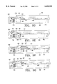
- FIG. 5 is an elevational view of a device of the present invention for introducing the implant into an eye
- FIG. 6 is a cross-sectional view taken in the plane including line 6--6 of FIG. 5;
- FIG. 7 shows the device of FIG. 5 introducing the implant into an eye
- FIG. 8 is a cross-sectional view of the device of FIG. 5 with a threaded connection between a slide and a body of the device;
- FIG. 9A is a cross-sectional view of the device of FIG. 5 with a locked connection between the slide and the body of the device;
- FIG. 9B is an exploded view of the device of FIG. 9A;
- FIG. 9C is a cross-sectional view of the device of FIG. 5 modified to include an implant separator for introducing multiple implants;
- FIGS. 9D-9G are schematic illustrations of a cartridge for use with the device of FIG. 5;
- FIG. 10 is a plan view of a second embodiment of a device of the present invention.
- FIG. 10A is an enlarged fragmentary view of the device of FIG. 10;
- FIG. 11 is a cross-sectional view taken in the plane including line 11--11 of FIG. 10A;
- FIG. 12 is a side view of the device of FIG. 10;
- FIG. 13 is a side view of a third embodiment of a device of the present invention.
- FIG. 14 is a cross-sectional fragmentary view taken in the plane including line 14--14 of FIG. 13;
- FIG. 15 is a schematic view showing the implant in an eye.
- FIG. 1 shows a horizontal cross-section of the eye with the globe 11 of the eye resembling a sphere with an anterior bulged spherical portion representing the cornea 12.
- the globe 11 of the eye consists of three concentric coverings enclosing the various transparent media through which the light must pass before reaching the light-sensitive retina 18.
- the outermost covering is a fibrous protective portion the posterior, five-sixths of which is white and opaque and called the sclera 13, and sometimes referred to as the white of the eye where visible to the front.
- the anterior one-sixth of this outer layer is the transparent cornea 12.
- a middle covering is mainly vascular and nutritive in function and is made up of the choroid, ciliary body 16, and iris 17.
- the choroid generally functions to maintain the retina 18.
- the ciliary body 16 is involved in suspending the lens 21 and accommodation of the lens.
- the iris 17 is the most anterior portion of the middle covering of the eye and is arranged in a frontal plane. It is a thin circular disc similar in function to the diaphragm of a camera, and is perforated near its center by a circular aperture called the pupil 19.
- the size of the pupil varies to regulate the amount of light which reaches the retina 18. It contracts also by accommodation, which serves to sharpen the focus by diminishing spherical aberration.
- the iris divides the space between the cornea 12 and the lens 21 into an anterior chamber 22 and the posterior chamber 23.
- the innermost portion of covering is the retina 18, consisting of nerve elements which form the true receptive portion for visual impressions.
- the retina 18 is a part of the brain arising as an outgrowth from the fore-brain, with the optic nerve 24 serving as a fiber tract connecting the retina part of the brain with the fore-brain.
- a layer of rods and cones, lying just beneath a pigmented epithelium on the anterior wall of the retina serve as visual cells or photoreceptors which transform physical energy (light) into nerve impulses.
- the vitreous body 26 is a transparent gelatinous mass which fills the posterior four-fifths of the globe 11. At its sides it supports the ciliary body 16 and the retina 18. A frontal saucer-shaped depression houses the lens.
- the lens 21 of the eye is a transparent bi-convex body of crystalline appearance placed between the iris 17 and vitreous body 26. Its axial diameter varies markedly with accommodation.
- a ciliary zonule 27, consisting of transparent fibers passing between the ciliary body 16 and lens 21 serves to hold the lens 21 in position and enables the ciliary muscle to act on it.
- this outermost fibrous transparent coating resembles a watch glass. Its curvature is somewhat greater than the rest of the globe and is ideally radially symmetric in nature. However, often it is more curved in one meridian than another giving rise to astigmatism. A central third of the cornea is called the optical zone with a slight flattening taking place outwardly thereof as the cornea thickens towards its periphery. Most of the refraction of the eye takes place through the cornea.
- FIG. 2 is a more detailed drawing of the anterior portion of the globe showing the various layers of the cornea 12 making up the epithelium 31.
- Epithelial cells on the surface thereof function to maintain transparency of the cornea 12. These epithelial cells are rich in glycogen, enzymes and acetylcholine and their activity regulates the corneal corpuscles and controls the transport of water and electrolytes through the lamellae of the stroma 32 of the cornea 12.
- An anterior limiting lamella 33 is positioned between the epithelium 31 and the stroma 32 of the cornea
- the corneal stroma 32 is made up of lamellae having bands of fibrils parallel to each other and crossing the whole of the cornea. While most of the fibrous bands are parallel to the surface, some are oblique, especially anteriorly.
- a posterior limiting lamella 34 is referred to as Descemet's membrane. It is a strong membrane sharply defined from the stroma 32 and resistant to pathological processes of the cornea.
- the endothelium 36 is the most posterior layer of the cornea and consists of a single layer of cells.
- the limbus 37 is the transition zone between the conjunctiva 38 and sclera on the one hand and the cornea 12 on the other.
- the present invention relates to the introduction of an implant 40 into the cornea 12, typically and desirably between the lamellar layers making up the cornea, in a position meridional to the cornea to alleviate abnormalities such as hyperopia.
- One or more of the implants 40 are typically inserted into the cornea 12 so that each subtends a portion of the meridian of the cornea outside of the cornea's central area, e.g., the area through which vision is achieved, but within the cornea's frontal diameter.
- FIGS. 3A and 3B show typical placement of the implants in the eye.
- FIG. 3A is a frontal view of the cornea 12 of an eye having six implants 40 which are located within small meridional pockets 42.
- a cross-sectional side view of the cornea 12 is shown in FIG. 3B.
- FIGS. 4A and 4B show one type of implant 40 which may be introduced into the eye by the devices of this invention.
- the implants 40 are preferably formed from a relatively stiff, physiologically acceptable polymer, but may be formed from other materials, or may be formed from a hybrid of different materials.
- the implant 40 has a central longitudinal axis A which may be arcuate or straight. As shown in FIG. 4B, the implant has a hexagonal shape as viewed in transverse cross section.
- the implant 40 may have a width W of between 0.2 mm and 2.0 mm, a thickness T of between 0.15 mm and 0.5 mm, and a length L less than 3.0 mm, for example.
- One or both of the ends of the implant 40 may also be tapered.
- the device 50 comprises a body 52 having a distal end 54 and a proximal end 56, a guide portion 55 disposed at the distal end of the body and forming a channel 53, and a member coupled to the body.
- the guide portion 55 of the body 52 is configured for laterally supporting the implant when positioned in the channel 53 and the member is arranged to axially support the implant when positioned in the channel.
- the member comprises a drive member or piston 58 with the arrangement of the piston and implant 40 being such that as the piston moves in a distal direction (to the left as viewed in FIG.
- the implant is urged along the channel 53 and into an incision formed in the corneal stroma, for introduction of the implant into the eye.
- a slide 60 extends from the distal end of the body 52 to guide the implant 40 and provide a surface against which the implant may slide to facilitate smooth insertion of the implant into the incision, as further described below.
- the implant is generally in its implanted configuration (FIG. 2, 3A, and 3B) when it is inserted into the device 50 and as it moves along channel 53, guide 55, and slide 60 of the device (FIGS. 6, 7, and 9C).
- the body 52 is a generally tubular elongated member having an inside diameter slightly larger than the diameter of the piston 58 to allow for smooth axial movement of the piston.
- the proximal end 56 of the body 52 may include a peripheral rim 64 for engagement by a surgeon's fingers to assist in actuation of the piston 58.
- the body 52 may be formed from metal, a rigid polymer, or any other suitable material.
- the piston 58 is in the form of a plunger similar in design to a plunger used in a syringe.
- the piston 58 comprises a rod 66, preferably having a length greater than the length of the body.
- a proximal end of the piston 58 has an enlarged portion 68 having a diameter greater than opening 70 in the proximal end 56 of the body 52 to limit the travel of the piston in the distal direction.
- the piston 58 is preferably sized such that when the enlarged portion 68 of the piston is in contact with the rim 64 of the body 52, the end of the piston rod 66 extends past the distal end 54 of the body so that the piston can push the entire implant 40 onto a surface of the slide 60.
- the piston 58 may be formed from metal, a stiff polymeric material or any other suitable material.
- the slide 60 is located at the distal end 54 of the body 52 and is sized to fit within an incision 62 to guide the implant through the incision and into a pocket (or channel) 72 extending from the incision (FIG. 7).
- the slide 60 extends from a forward side of the body 52 and is preferably curved in a forward direction away from a central longitudinal axis A 1 of the device 50 so that the implant 40 is located rearward of the slide as it exits the body. This configuration allows the device 50 to guide the implant past a comer 74 defined by the intersection of the incision 62 and the pocket 72 (as further described below).
- the slide 60 is preferably formed from a rigid material to compress comer 74 to allow the implant 40 to move easily past the comer.
- the slide 60 may also be formed from a flexible material to allow the slide to bend around the comer 74.
- the width W G of the slide 60 is preferably greater than the width W of the implant 40, and the length of the slide is preferably greater than the depth of the incision (FIGS. 4B and 5).
- the slide 60 may have configurations other than the one shown without departing from the scope of the invention.
- the slide 60 may be straight for insertion into only the incision 62 rather than both the incision and the pocket 72.
- the slide 60 may be permanently attached to the body 52 by soldering, adhesives or any other suitable means.
- the slide 60 may also be removably connected to body 52 as described below.
- the device 50 further includes a retaining member or ring 76 extending from the body 52 to the slide 60 to retain the implant 40 within the device prior to introducing the implant into the eye (FIG. 6).
- the ring 76 comprises a first portion 78 which is generally cylindrical in shape and sized to fit over the distal end 54 of the body 52, and a second portion 80 having a generally tapered surface extending from the first portion to a distal end 82 of the ring.
- the distal end 82 of the ring 76 has a width W R slightly larger than the width W G of the slide 60 so that the ring may extend over the slide.
- the ring 76 is formed from a resilient, expansible material which stretches to allow the implant 40 to pass through an opening 85 in the distal end 82 of the ring. As shown in FIG. 6, the opening 85 is sized so that the implant 40 must be pushed out from the ring 76 by the piston 58. As the piston 58 moves the implant 40 in the distal direction, the implant causes the opening 85 in the ring 76 to expand so that the insert can pass through. This design prevents the implant 40 from inadvertently falling out of the body 52 through the opening 85 in the ring 76.
- a ring 86 may also be sized to allow the implant 40 to pass freely therethrough without requiring the material of the ring to stretch (see FIG. 8).
- the ring 76, 86 is preferably formed from a smooth material which is compatible with the eye to prevent damage to the cornea 12 if the ring contacts the cornea.
- the ring 76, 86 may be configured for insertion into a portion of the incision 62, or may include a shoulder (not shown) for engagement with the cornea so that the device may rest on the cornea during introduction of the implant into the eye.
- the distal end of the ring 76, 86 may also beveled to prevent inadvertent contact with the cornea.
- the retaining member may comprise a flap disposed on the distal end 54 of the body 52 to hold the implants in place within the device.
- FIG. 8 shows a slide 88 which is threadably connected to a body 89 for easy removal and replacement of the slide.
- the slide 88 has a stem 90 extending from the end opposite the curved end of the slide.
- the stem 90 is hollow and generally cylindrical in shape.
- External threads 92 are formed on an outer surface of the stem 90.
- the body 89 has internal threads 94 formed thereon for mating with the external threads 92 on the stem 90 of the slide 88.
- FIGS. 9A and 9B A locking connection between a slide 96 and a body 98 is shown in FIGS. 9A and 9B.
- the body 98 includes a first locking element 100 for engagement with a second locking element 102 formed on a stem 104 of the slide 96.
- the locking element 102 of the slide 96 snaps into the locking element 100 of the body 98.
- Other types of locking or interengageable components may be used to removably connect the slide 96 to the body 98.
- FIG. 9C shows a modification of the body and piston of the device 50 of FIG. 5.
- the inner diameter of a body 53 of the device has a groove 55 formed therein for receiving the implants 40.
- a piston 57 includes an implant separator 59 at a distal end thereof for separating the implants 40 so that only one implant at a time is dispensed from the device.
- the implant separator 59 is integrally formed with the piston rod 61 and is bent downward from a distal end of the piston rod.
- the implant separator 59 engages one end of the implant 40 located at the distal end 63 of the body 53, and pushes the implant along the slide 60.
- the piston 57 is then pulled in the proximal direction until the implant separator 59 engages the proximal end of the next implant.
- the piston rod 61 may have markings on it to show how far to pull the piston 57 from the body 53 in order to engage the next implant 40.
- the piston 57 is preferably stiff and may be formed from a cold worked stainless steel, nitinol, or any other suitable material.
- a cartridge for use with the device 50 (FIG. 5) is schematically shown in FIGS. 9D-9G, and generally indicated at 65.
- the cartridge 65 may be inserted into body 52 to replace the piston 57 of device 50.
- the cartridge comprises a piston 67 slidable along a support 69, a lever 71 pivotally mounted on the support, a lever spring 73 for biasing the lever to a closed position, and a feeder spring 75.
- the piston 67 has a longitudinal channel 77 formed on a bottom side thereof for storing the implants 40.
- a pusher 79 extends from an upper side of the piston 67 and is used to push the implants 40 onto a guide surface 81 which is aligned with the slide 60 (shown in FIG. 5).
- the piston 67 also includes a camming surface 91 for engagement with lever 71.
- the lever 71 is pivotally connected to the support 69 by a pivot pin 83, and has an opening 85 for receiving a portion of the support upon which the lever slides in a generally radial direction.
- the lever 71 is movable between a closed position (FIG. 9F) in which the implants 40 are retained within the channel 77, and an open position (FIG. 9E) in which an implant 40 may be moved from the channel onto an upper surface of the lever.
- Operation of the cartridge 65 is as follows.
- the implants 40 are placed on the support 69 and the piston 67 is positioned over the implants with the implants disposed within the channel 77 formed on the bottom side of the piston (FIG. 9D).
- the lever 71 is in its normally closed position with the lever spring 73 forcing the lever against the piston 67.
- the piston 67 is moved in a distal direction (to the left as viewed in FIG. 9E) and the camming surface 91 of the piston forces the lever downward into its open position.
- the piston 67 is then moved in a proximal direction to allow the lever 71 to move back to its closed position and push the implant 40 upward (FIG. 9F).
- the piston is next moved once again in the distal direction and the pusher 79 pushes the implant 40 onto the guide surface 81 and onto the slide 60 (FIGS. 6 and 9G).
- the implants 40 are constantly moved in the distal direction towards the lever by the feeder spring 75 which is connected to the support at 93.
- the cartridge 65 may also be used alone without the body 52 and slide 60 of device 50.
- the cartridge 65 may be loaded with the implants 40, and then sterilized and packaged, or the cartridge and implants may be inserted into the body 52 and sterilized and packaged as a complete device.
- a second embodiment of the present invention is generally indicated at 110 and shown in FIGS. 10-12.
- the device 110 comprises a body 112, a guide portion 114, and a piston 116 axially slidable in the body.
- the body 112 comprises a generally U-shaped member having two arms 118 extending generally parallel to a central longitudinal axis A 2 of the body, and forming a longitudinal slot 122 therebetween. End portions (or fingers) 120 of the arms 118 constitute the guide portion 114.
- the arms 118 are movably biased towards one another and are movable in a direction generally transverse to the longitudinal axis A 2 of the body 112.
- a cam 124 is connected to the piston 116 and is axially slidable along the slot 122 to urge the arms 118 outward and spread the fingers 120.
- Ramps 126 project from each arm into the slot 122 to provide camming surfaces for the cam 124.
- the cam 124 is located in a position distal to the ramps 126 when the fingers are in a closed position. As the cam 124 is moved in a proximal direction (to the left as viewed in FIG. 10) along the slot 122, the cam engages the ramps 126 and forces the arms 118 apart, thus causing the fingers 120 to move away from one another into an open position for loading the implants 40 into the device 110.
- the arms 118 may be bent so that the cam 124 engages the arms directly to open fingers 120, thus eliminating the ramps 126.
- the arms may also be formed as two separate pieces and attached to one another at their proximal ends.
- Each finger 120 has a longitudinal groove 128 formed therein (FIG. 10A).
- the grooves 128 define a channel having a transverse cross-sectional shape corresponding to the transverse cross-sectional shape of the implant 40 (FIG. 11).
- the grooves 128 preferably have smooth surfaces to prevent damage to the implant as it moves through the channel.
- the piston 116 is operable to push the implant 40 along the channel and into the incision as the piston moves in a distal direction.
- a pusher 130 is disposed above the cam 124 and arranged for actuation by a surgeon's thumb for simple one handed operation.
- the upper surface of the pusher 130 may be formed with ridges to increase the friction between the surgeon's thumb and the pusher for ease of operation.
- the piston 116 may be configured for actuation by a surgeon's index finger rather than the surgeon's thumb.
- the piston 116 may also be actuated by a rotary device (not shown) which causes axial movement of the piston to move the implant 40.
- a slide 60 similar to the one shown in the first embodiment 50, may also be attached to the ends of the fingers 120 to facilitate inserting and positioning the implants 40 in the incision 62 and pockets 72.
- the piston 116 and cam 124 may also be arranged to move in the same direction so that when the piston pushes the implant 40 towards the distal end of the fingers 120, the cam spreads the fingers apart.
- FIG. 13 A third embodiment of the present invention is shown in FIG. 13 and generally indicated at 140.
- the device 140 has two grasping fingers 144 (defining the guide portion), movable towards one another for holding the implant 40.
- the device has a stop (or flange) 142 to prevent the implant 40 from backing out from between the fingers 144.
- the fingers 144 preferably have grooves 146 formed therein to define a channel having a transverse cross-sectional shape generally corresponding to the transverse cross-sectional shape of the implant (FIG. 14).
- the stop 142 is attached to one side of one of the fingers 144 by welding, glue, or any other suitable method.
- the stop 142 may also be integrally formed with one of the fingers 144.
- the stop 142 is also used to apply a direct axial force to one end of the implant 40 to assist in pushing the implant into the incision 62 and manipulating the implant into its proper position.
- the device 140 may also have hinge operated fingers (not shown) similar to forceps available from Dutch Ophthalmic Research Center International (D.O.R.C.) of Springfield, N.H., under trade designation MICROFORCEPS 1286C or 1286 DIA.
- the forceps include a sleeve which is axially movable in one direction to extend partially over the fingers and force the fingers into a closed position, and in the opposite direction to allow the fingers to spread apart.
- a flexible hinge is fixedly connected to the sleeve and actuated by movement in the radial direction to cause axial movement of the sleeve.
- the hinge is normally biased to a position in which the fingers are spread apart.
- FIG. 15 shows a small circumferential incision 150 and a meridional pocket 152 for placement of the implant.
- the incision 150 is shown located within the cornea 12, but the incision may also be made outside of the cornea 12, within the limbus of the eye.
- the pocket 152 is formed by inserting a blade of a pocket-forming device (not shown) through the incision 150 to separate stroma layers to form the pocket.
- the blade creates a stromal delamination for receiving the implant.
- the length, width and shape of the pocket are determined by the size and shape of the blade.
- the implant 40 is then introduced through the incision and into the pocket 152.
- a suitable positioning device may be used to properly position the implant 40 within the pocket.
- the initial incision 150 may be closed by use of sutures, glue, staples, or by electrosurgical welding. It is to be understood that various other methods may be used to create the channels or pockets for the implants and other configurations or number of implants may be used without departing from the scope of the invention.
- one or more implants 40 are first loaded into the device (FIG. 6).
- the implant 40 is preferably loaded from the proximal end 56 of the body 52 by removing the piston 58 and placing the implants into the body lengthwise.
- the implant 40 may also be loaded into the distal end 54 of the body 52 through the ring 76.
- the device 50 is loaded, it is placed near the incision 62 and the slide 60 is inserted into the incision (FIG. 7).
- the slide 60 is positioned adjacent to an upper edge 160 of the pocket 72.
- the piston 58 is slowly actuated to advance the implant 40 into the incision 62, rearward of the slide 60.
- the slide 60 prevents the implant 40 from getting caught on the comer 74 and allows for smooth insertion and positioning of the implant. After the implant 40 is properly inserted into the pocket 72, the slide 60 is removed from the incision 62. Multiple implants 40 may be inserted through the same incision 62.
- the device 110 of the second embodiment is loaded axially from the open end of the fingers 120 (FIG. 10).
- the pusher 130 is moved in the proximal direction until the cam 124 engages the ramps 126 extending from the arms 118.
- the fingers 120 are now spread apart and the implant 40 may be loaded into the fingers.
- the pusher 130 is then moved in the distal direction to close the fingers 120 to grasp the implant 40.
- the device 110 is positioned over the incision and the pusher 130 is moved in the distal direction to introduce the implant 40 into the incision.
- An implant 40 is inserted into the fingers 144 of the device 140 of the third embodiment in a method similar to the grasping of an implant with standard forceps, except that the implant is positioned with one end contiguous with the stop 142 (FIG. 13). The opposite end of the implant 40 is then inserted into the incision and the stop 142 prevents the implant from backing out from between the fingers 144. The stop 142 also helps to push the implant 40 into the incision and properly position the implant.
- the devices may be sterilized using known procedures with sterilants such as ethylene oxide, radiation, or any other suitable sterilant.
- the devices are preferably packaged in a sterilized condition.
- the implants may be loaded into the devices and packaged with the device.
- the implants may also be loaded into a cartridge which may be inserted into the device.
- the device can then be reused by inserting a new cartridge.
- the packaging may by dry and include an inert gas or contain a sterile fluid such as saline solution.
- the devices of the present invention have numerous advantages over the prior art.
- the devices provide for simple and accurate placement of the implants into the corneal stroma of the eye.
- the design of the devices allows for single-handed operation by the surgeon and allows for the introduction of multiple implants into the eye at one time.
- the implants may be loaded into the device and packaged with the device.
Abstract
Description
Claims (30)
Priority Applications (3)
| Application Number | Priority Date | Filing Date | Title |
|---|---|---|---|
| US08/993,594 US6050999A (en) | 1997-12-18 | 1997-12-18 | Corneal implant introducer and method of use |
| AU22018/99A AU2201899A (en) | 1997-12-18 | 1998-12-18 | Corneal implant introducer |
| PCT/US1998/027099 WO1999030644A1 (en) | 1997-12-18 | 1998-12-18 | Corneal implant introducer |
Applications Claiming Priority (1)
| Application Number | Priority Date | Filing Date | Title |
|---|---|---|---|
| US08/993,594 US6050999A (en) | 1997-12-18 | 1997-12-18 | Corneal implant introducer and method of use |
Publications (1)
| Publication Number | Publication Date |
|---|---|
| US6050999A true US6050999A (en) | 2000-04-18 |
Family
ID=25539736
Family Applications (1)
| Application Number | Title | Priority Date | Filing Date |
|---|---|---|---|
| US08/993,594 Expired - Fee Related US6050999A (en) | 1997-12-18 | 1997-12-18 | Corneal implant introducer and method of use |
Country Status (3)
| Country | Link |
|---|---|
| US (1) | US6050999A (en) |
| AU (1) | AU2201899A (en) |
| WO (1) | WO1999030644A1 (en) |
Cited By (127)
| Publication number | Priority date | Publication date | Assignee | Title |
|---|---|---|---|---|
| WO2001050943A2 (en) * | 2000-01-12 | 2001-07-19 | Becton, Dickinson And Company | Systems and methods for reducing intraocular pressure |
| US20020116056A1 (en) * | 2000-12-21 | 2002-08-22 | Kirk James F. | Device for controllably altering the curvature of the cornea |
| US20030099024A1 (en) * | 2001-11-28 | 2003-05-29 | Lg Electronics Inc. | Apparatus and method for energy recovery |
| US20030187385A1 (en) * | 2000-04-14 | 2003-10-02 | Bergheim Olav B. | Implant with anchor |
| US20030229358A1 (en) * | 2001-07-16 | 2003-12-11 | Errico Joseph P. | Wedge plate inserter/impactor and related methods for use in implanting an artificial intervertebral disc |
| US20040024345A1 (en) * | 2002-04-19 | 2004-02-05 | Morteza Gharib | Glaucoma implant with valveless flow bias |
| US20040102729A1 (en) * | 2002-04-08 | 2004-05-27 | David Haffner | Devices and methods for glaucoma treatment |
| US20040111050A1 (en) * | 2000-04-14 | 2004-06-10 | Gregory Smedley | Implantable ocular pump to reduce intraocular pressure |
| US20040127843A1 (en) * | 2000-04-14 | 2004-07-01 | Hosheng Tu | Glaucoma implant with therapeutic agents |
| US6761724B1 (en) * | 1997-09-19 | 2004-07-13 | Eberhard-Karls-Universität Tübingen Universitätsklinikum | Method and device for entering the subretinal region of the eye |
| US20040147870A1 (en) * | 2002-04-08 | 2004-07-29 | Burns Thomas W. | Glaucoma treatment kit |
| US20040167534A1 (en) * | 2001-07-16 | 2004-08-26 | Errico Joseph P. | Instrumentation for inserting and impacting an artificial intervertebral disc in an intervertebral space |
| US20040167555A1 (en) * | 2001-07-23 | 2004-08-26 | Fos Holding S.A. | Device for separating the epithelium layer from the surface of the cornea of an eye |
| US20040204762A1 (en) * | 2001-10-01 | 2004-10-14 | Ralph James D. | Intervertebral spacer device utilizing a spirally slotted belleville washer having radially spaced concentric grooves |
| US20050049578A1 (en) * | 2000-04-14 | 2005-03-03 | Hosheng Tu | Implantable ocular pump to reduce intraocular pressure |
| US20050090807A1 (en) * | 1999-04-26 | 2005-04-28 | Gmp Vision Solutions, Inc. | Shunt device and method for treating glaucoma |
| US20050113844A1 (en) * | 2000-09-12 | 2005-05-26 | Alok Nigam | System for packaging and handling an implant and method of use |
| US20050119737A1 (en) * | 2000-01-12 | 2005-06-02 | Bene Eric A. | Ocular implant and methods for making and using same |
| US20050192527A1 (en) * | 2001-05-02 | 2005-09-01 | Morteza Gharib | Glaucoma implant with extending members |
| US20050246016A1 (en) * | 2004-04-30 | 2005-11-03 | Intralens Vision, Inc. | Implantable lenses with modified edge regions |
| US20050246015A1 (en) * | 2004-04-30 | 2005-11-03 | Troy Miller | Aspherical corneal implant |
| US20050250788A1 (en) * | 2004-01-30 | 2005-11-10 | Hosheng Tu | Aqueous outflow enhancement with vasodilated aqueous cavity |
| US20050266047A1 (en) * | 2002-04-08 | 2005-12-01 | Hosheng Tu | Injectable glaucoma implants with multiple openings |
| US20050271704A1 (en) * | 2002-04-08 | 2005-12-08 | Hosheng Tu | Injectable glaucoma implants with multiple openings |
| US20050277864A1 (en) * | 2000-04-14 | 2005-12-15 | David Haffner | Injectable gel implant for glaucoma treatment |
| US20050283163A1 (en) * | 2004-06-04 | 2005-12-22 | Valdemar Portney | Intraocular lens implanting instrument |
| US20060036269A1 (en) * | 2001-02-23 | 2006-02-16 | Ras Holding Corp | Surgical blade for use with a surgical tool for making incisions for scleral eye implants |
| US20060173539A1 (en) * | 2005-01-31 | 2006-08-03 | Yichieh Shiuey | Corneal implants and methods and systems for placement |
| US20060235430A1 (en) * | 2005-04-15 | 2006-10-19 | Intralens Vision, Inc. | Corneal implant injector assembly and methods of use |
| US20060241749A1 (en) * | 2001-08-28 | 2006-10-26 | Hosheng Tu | Glaucoma stent system |
| US20070112292A1 (en) * | 2001-04-07 | 2007-05-17 | Hosheng Tu | Glaucoma stent and methods thereof for glaucoma treatment |
| US20070129797A1 (en) * | 2005-12-01 | 2007-06-07 | Revision Optics, Inc. | Intracorneal inlays |
| US20070203577A1 (en) * | 2006-02-24 | 2007-08-30 | Revision Optics, Inc. | Small Diameter Inlays |
| US20070219631A1 (en) * | 2006-03-17 | 2007-09-20 | Addition Technology, Inc. | Pre-formed intrastromal corneal insert for corneal abnormalities or dystrophies |
| US20070244559A1 (en) * | 2005-01-31 | 2007-10-18 | Yichieh Shiuey | Corneal Implants and Methods and Systems for Placement |
| US20070255401A1 (en) * | 2006-05-01 | 2007-11-01 | Revision Optics, Inc. | Design of Inlays With Intrinsic Diopter Power |
| US20070293807A1 (en) * | 2006-05-01 | 2007-12-20 | Lynch Mary G | Dual drainage pathway shunt device and method for treating glaucoma |
| US20080015488A1 (en) * | 2001-05-03 | 2008-01-17 | Glaukos Corporation | Glaucoma implant with double anchor mechanism |
| US20080077229A1 (en) * | 2004-06-28 | 2008-03-27 | Xtent, Inc. | Custom-length self-expanding stent delivery systems with stent bumpers |
| US20080172204A1 (en) * | 2007-01-15 | 2008-07-17 | Fujitsu Limited | Step counter and method of counting steps |
| US20080243138A1 (en) * | 2007-03-28 | 2008-10-02 | Jon Dishler | Insertion system for corneal implants |
| US20080262610A1 (en) * | 2007-04-20 | 2008-10-23 | Alan Lang | Biomechanical design of intracorneal inlays |
| US20090021692A1 (en) * | 1999-03-01 | 2009-01-22 | Boston Innovative Optics, Inc. | System and method for increasing the depth of focus of the human eye |
| WO2009046158A1 (en) * | 2007-10-02 | 2009-04-09 | Mayo Foundation For Medical Education And Research | Keratoplasty graft deployment devices and methods |
| US20090306773A1 (en) * | 2008-06-04 | 2009-12-10 | Acufocus, Inc. | Opaque corneal insert for refractive correction |
| US20100069915A1 (en) * | 2005-01-31 | 2010-03-18 | Yichieh Shiuey | Corneal implants and methods and systems for placement |
| US20100076506A1 (en) * | 2003-03-06 | 2010-03-25 | Spinecore, Inc. | Instrumentation and methods for use in implanting a cervical disc replacement device |
| US20100100186A1 (en) * | 2003-03-06 | 2010-04-22 | Spinecore, Inc. | Instrumentation and methods for use in implanting a cervical disc replacement device |
| US20100106073A1 (en) * | 2001-05-02 | 2010-04-29 | Glaukos Corporation | Method of monitoring intraocular pressure and treating an ocular disorder |
| US20110022148A1 (en) * | 2007-02-20 | 2011-01-27 | Xtent, Inc. | Thermo-mechanically controlled implants and methods of use |
| US20110028884A1 (en) * | 2003-11-14 | 2011-02-03 | Minas Theodore Coroneo | Ocular pressure regulation |
| US20110028883A1 (en) * | 2006-01-17 | 2011-02-03 | Juan Jr Eugene De | Glaucoma treatment device |
| US20110125248A1 (en) * | 2001-12-03 | 2011-05-26 | Xtent, Inc. | Custom length stent apparatus |
| US7951155B2 (en) | 2002-03-15 | 2011-05-31 | Glaukos Corporation | Combined treatment for cataract and glaucoma treatment |
| US20110152996A1 (en) * | 2001-12-03 | 2011-06-23 | Xtent, Inc. | Apparatus and methods for delivery of multiple distributed stents |
| US20110172675A1 (en) * | 2010-01-12 | 2011-07-14 | Acufocus, Inc. | Ocular inlay delivery system and method of use |
| US20110196381A1 (en) * | 2010-02-11 | 2011-08-11 | Presbitech, Inc. | Lens Inserter Apparatus and Method |
| US20110218623A1 (en) * | 2004-04-30 | 2011-09-08 | Jon Dishler | Small Diameter Inlays |
| US8029568B2 (en) | 2001-10-18 | 2011-10-04 | Spinecore, Inc. | Intervertebral spacer device having a slotted partial circular domed arch strip spring |
| US8092539B2 (en) | 2001-10-01 | 2012-01-10 | Spinecore, Inc. | Intervertebral spacer device having a belleville washer with concentric grooves |
| US20120203238A1 (en) * | 2000-09-12 | 2012-08-09 | Revision Optics, Inc. | System for Packaging and Handling an Implant and Method of Use |
| US8277507B2 (en) | 2002-04-12 | 2012-10-02 | Spinecore, Inc. | Spacerless artificial disc replacements |
| US8470041B2 (en) | 2002-04-12 | 2013-06-25 | Spinecore, Inc. | Two-component artificial disc replacements |
| US8469948B2 (en) | 2010-08-23 | 2013-06-25 | Revision Optics, Inc. | Methods and devices for forming corneal channels |
| US8506515B2 (en) | 2006-11-10 | 2013-08-13 | Glaukos Corporation | Uveoscleral shunt and methods for implanting same |
| US8597318B2 (en) | 2011-08-08 | 2013-12-03 | Refocus Group, Inc. | Apparatus and method for forming incisions in ocular tissue |
| US8617094B2 (en) | 2002-03-07 | 2013-12-31 | Glaukos Corporation | Fluid infusion methods for glaucoma treatment |
| US8668735B2 (en) * | 2000-09-12 | 2014-03-11 | Revision Optics, Inc. | Corneal implant storage and delivery devices |
| US20140277429A1 (en) * | 2013-03-12 | 2014-09-18 | Oculeve, Inc. | Implant delivery devices, systems, and methods |
| US8864824B2 (en) | 2003-06-17 | 2014-10-21 | Acufocus, Inc. | Method and apparatus for aligning a mask with the visual axis of an eye |
| US8900296B2 (en) | 2007-04-20 | 2014-12-02 | Revision Optics, Inc. | Corneal inlay design and methods of correcting vision |
| US8945038B2 (en) | 2003-05-05 | 2015-02-03 | Transcend Medical, Inc. | Internal shunt and method for treating glaucoma |
| JP2015517836A (en) * | 2012-03-26 | 2015-06-25 | グローコス コーポレーション | System and method for delivering multiple ocular implants |
| US9101503B2 (en) | 2008-03-06 | 2015-08-11 | J.W. Medical Systems Ltd. | Apparatus having variable strut length and methods of use |
| US9155656B2 (en) | 2012-04-24 | 2015-10-13 | Transcend Medical, Inc. | Delivery system for ocular implant |
| WO2015161069A1 (en) * | 2014-04-16 | 2015-10-22 | Revision Optics, Inc. | Corneal inlay delivery devices and methods |
| US9204962B2 (en) | 2013-03-13 | 2015-12-08 | Acufocus, Inc. | In situ adjustable optical mask |
| US9271828B2 (en) | 2007-03-28 | 2016-03-01 | Revision Optics, Inc. | Corneal implant retaining devices and methods of use |
| US9339404B2 (en) | 2007-03-22 | 2016-05-17 | J.W. Medical Systems Ltd. | Devices and methods for controlling expandable prostheses during deployment |
| US9345569B2 (en) | 2011-10-21 | 2016-05-24 | Revision Optics, Inc. | Corneal implant storage and delivery devices |
| US9427922B2 (en) | 2013-03-14 | 2016-08-30 | Acufocus, Inc. | Process for manufacturing an intraocular lens with an embedded mask |
| US9480598B2 (en) | 2012-09-17 | 2016-11-01 | Novartis Ag | Expanding ocular implant devices and methods |
| US9539143B2 (en) | 2008-04-04 | 2017-01-10 | Revision Optics, Inc. | Methods of correcting vision |
| US9545303B2 (en) | 2011-12-02 | 2017-01-17 | Acufocus, Inc. | Ocular mask having selective spectral transmission |
| US9549848B2 (en) | 2007-03-28 | 2017-01-24 | Revision Optics, Inc. | Corneal implant inserters and methods of use |
| US9566179B2 (en) | 2003-12-23 | 2017-02-14 | J.W. Medical Systems Ltd. | Devices and methods for controlling and indicating the length of an interventional element |
| US9592151B2 (en) | 2013-03-15 | 2017-03-14 | Glaukos Corporation | Systems and methods for delivering an ocular implant to the suprachoroidal space within an eye |
| US20170079772A1 (en) * | 2014-03-19 | 2017-03-23 | Hoya Corporation | Intraocular lens injector and intraocular lens injection device |
| US9687652B2 (en) | 2014-07-25 | 2017-06-27 | Oculeve, Inc. | Stimulation patterns for treating dry eye |
| US9700448B2 (en) | 2004-06-28 | 2017-07-11 | J.W. Medical Systems Ltd. | Devices and methods for controlling expandable prostheses during deployment |
| US9730638B2 (en) | 2013-03-13 | 2017-08-15 | Glaukos Corporation | Intraocular physiological sensor |
| US9737712B2 (en) | 2014-10-22 | 2017-08-22 | Oculeve, Inc. | Stimulation devices and methods for treating dry eye |
| US9763828B2 (en) | 2009-01-28 | 2017-09-19 | Novartis Ag | Ocular implant with stiffness qualities, methods of implantation and system |
| US9764150B2 (en) | 2014-10-22 | 2017-09-19 | Oculeve, Inc. | Contact lens for increasing tear production |
| US9763829B2 (en) | 2012-11-14 | 2017-09-19 | Novartis Ag | Flow promoting ocular implant |
| US9821159B2 (en) | 2010-11-16 | 2017-11-21 | The Board Of Trustees Of The Leland Stanford Junior University | Stimulation devices and methods |
| US9855167B2 (en) | 2012-03-20 | 2018-01-02 | Sight Sciences, Inc. | Ocular delivery systems and methods |
| US9883957B2 (en) | 2006-03-20 | 2018-02-06 | J.W. Medical Systems Ltd. | Apparatus and methods for deployment of linked prosthetic segments |
| US9987163B2 (en) | 2013-04-16 | 2018-06-05 | Novartis Ag | Device for dispensing intraocular substances |
| US10085633B2 (en) | 2012-04-19 | 2018-10-02 | Novartis Ag | Direct visualization system for glaucoma treatment |
| US10143846B2 (en) | 2010-11-16 | 2018-12-04 | The Board Of Trustees Of The Leland Stanford Junior University | Systems and methods for treatment of dry eye |
| US10207108B2 (en) | 2014-10-22 | 2019-02-19 | Oculeve, Inc. | Implantable nasal stimulator systems and methods |
| US10252048B2 (en) | 2016-02-19 | 2019-04-09 | Oculeve, Inc. | Nasal stimulation for rhinitis, nasal congestion, and ocular allergies |
| USD846738S1 (en) | 2017-10-27 | 2019-04-23 | Glaukos Corporation | Implant delivery apparatus |
| US10299958B2 (en) | 2015-03-31 | 2019-05-28 | Sight Sciences, Inc. | Ocular delivery systems and methods |
| US10314742B2 (en) | 2006-06-26 | 2019-06-11 | Sight Sciences, Inc. | Intraocular implants and methods and kits therefor |
| US10406030B2 (en) | 2010-02-05 | 2019-09-10 | Sight Sciences, Inc. | Intraocular implants and related kits and methods |
| US10426958B2 (en) | 2015-12-04 | 2019-10-01 | Oculeve, Inc. | Intranasal stimulation for enhanced release of ocular mucins and other tear proteins |
| US10517717B2 (en) | 2008-06-05 | 2019-12-31 | Hoya Corporation | Intraocular lens insertion device and cartridge |
| US10555805B2 (en) | 2006-02-24 | 2020-02-11 | Rvo 2.0, Inc. | Anterior corneal shapes and methods of providing the shapes |
| US10583041B2 (en) | 2015-03-12 | 2020-03-10 | RVO 2.0 Inc. | Methods of correcting vision |
| US10610095B2 (en) | 2016-12-02 | 2020-04-07 | Oculeve, Inc. | Apparatus and method for dry eye forecast and treatment recommendation |
| US10675145B2 (en) | 2010-09-30 | 2020-06-09 | KeraMed, Inc. | Corneal implants |
| US10799695B2 (en) | 2013-04-19 | 2020-10-13 | Oculeve, Inc. | Nasal stimulation devices and methods |
| US10799339B2 (en) | 2015-09-16 | 2020-10-13 | Hoya Corporation | Intraocular lens injector |
| US10799696B2 (en) | 2014-02-25 | 2020-10-13 | Oculeve, Inc. | Polymer formulations for nasolacrimal stimulation |
| US10806631B2 (en) | 2017-08-23 | 2020-10-20 | Refocus Group, Inc. | Surgical tool for forming incisions in ocular tissue with tip providing visibility and related apparatus and method |
| US10835371B2 (en) | 2004-04-30 | 2020-11-17 | Rvo 2.0, Inc. | Small diameter corneal inlay methods |
| US10849738B2 (en) | 2015-09-16 | 2020-12-01 | Hoya Corporation | Intraocular lens injector |
| US10918474B2 (en) | 2017-09-11 | 2021-02-16 | Industrial Technology Research Institute | Implanting device |
| US10918864B2 (en) | 2016-05-02 | 2021-02-16 | Oculeve, Inc. | Intranasal stimulation for treatment of meibomian gland disease and blepharitis |
| US11033382B2 (en) | 2016-06-28 | 2021-06-15 | Hoya Corporation | Intraocular lens injector |
| US11116625B2 (en) | 2017-09-28 | 2021-09-14 | Glaukos Corporation | Apparatus and method for controlling placement of intraocular implants |
| US11363951B2 (en) | 2011-09-13 | 2022-06-21 | Glaukos Corporation | Intraocular physiological sensor |
| US11376040B2 (en) | 2017-10-06 | 2022-07-05 | Glaukos Corporation | Systems and methods for delivering multiple ocular implants |
| US11504270B1 (en) | 2019-09-27 | 2022-11-22 | Sight Sciences, Inc. | Ocular delivery systems and methods |
| US11617643B2 (en) | 2007-05-30 | 2023-04-04 | Hoya Corporation | Intraocular lens insertion device |
Families Citing this family (6)
| Publication number | Priority date | Publication date | Assignee | Title |
|---|---|---|---|---|
| US6358261B1 (en) | 1999-11-05 | 2002-03-19 | Alcon Universal Ltd. | Lamellar dissecting instrument |
| US6358262B1 (en) | 1999-11-05 | 2002-03-19 | Alcon Universal Ltd. | Lamellar dissecting instrument |
| GB0010871D0 (en) * | 2000-05-06 | 2000-06-28 | Duckworth & Kent Ltd | Opthalmic injector |
| AU2002317086A1 (en) * | 2002-06-28 | 2004-02-16 | 3062696 Nova Scotia Limited | Pupil dilating device and apparatus for use therewith |
| AU2011253668B2 (en) * | 2003-08-05 | 2015-11-05 | Glaukos Corporation | Devices and methods for glaucoma treatment |
| AR110649A1 (en) * | 2017-11-29 | 2019-04-17 | Albertazzi Roberto Gustavo | INTRACTOR INJECTOR AND SEGMENT TO TREAT CORNEAL DISORDERS |
Citations (33)
| Publication number | Priority date | Publication date | Assignee | Title |
|---|---|---|---|---|
| US4014335A (en) * | 1975-04-21 | 1977-03-29 | Alza Corporation | Ocular drug delivery device |
| US4086914A (en) * | 1977-02-11 | 1978-05-02 | Edwin Bailey Moore | Implant injector |
| US4451254A (en) * | 1982-03-15 | 1984-05-29 | Eli Lilly And Company | Implant system |
| US4452235A (en) * | 1982-01-04 | 1984-06-05 | Reynolds Alvin E | Method for corneal curvature adjustment |
| US4481948A (en) * | 1980-12-29 | 1984-11-13 | Sole Gary M | Medical instrument, and methods of constructing and utilizing same |
| US4573998A (en) * | 1982-02-05 | 1986-03-04 | Staar Surgical Co. | Methods for implantation of deformable intraocular lenses |
| US4607617A (en) * | 1980-08-05 | 1986-08-26 | Choyce David P | Apparatus and method for improving eyesight |
| US4688570A (en) * | 1981-03-09 | 1987-08-25 | The Regents Of The University Of California | Ophthalmologic surgical instrument |
| US4815463A (en) * | 1983-12-21 | 1989-03-28 | Laboratoire Hydron | Surgical apparatus for radial keratotomy |
| US4834094A (en) * | 1987-10-07 | 1989-05-30 | Patton Medical Technologies, Inc. | "Canoe" apparatus for inserting intra-ocular lens into the eye |
| US4941093A (en) * | 1985-09-12 | 1990-07-10 | Summit Technology, Inc. | Surface erosion using lasers |
| US4950272A (en) * | 1989-06-19 | 1990-08-21 | Smirmaul Heinz J | Surgical instrument and method for removing the lens of an eye |
| EP0392773A2 (en) * | 1989-04-12 | 1990-10-17 | Allergan, Inc | Small incision intraocular lens insertion apparatus |
| US5090955A (en) * | 1990-07-12 | 1992-02-25 | University Of Miami | Gel injection adjustable keratoplasty |
| US5098443A (en) * | 1989-03-23 | 1992-03-24 | University Of Miami | Method of implanting intraocular and intraorbital implantable devices for the controlled release of pharmacological agents |
| US5123905A (en) * | 1991-06-07 | 1992-06-23 | Kelman Charles D | Intraocular lens injector |
| US5188125A (en) * | 1982-01-04 | 1993-02-23 | Keravision, Inc. | Method for corneal curvature adjustment |
| US5190552A (en) * | 1992-02-04 | 1993-03-02 | Kelman Charles D | Slotted tube injector for an intraocular lens |
| US5242373A (en) * | 1991-09-17 | 1993-09-07 | Scott Walter P | Medical seed implantation instrument |
| US5242449A (en) * | 1991-04-23 | 1993-09-07 | Allergan, Inc. | Ophthalmic instrument |
| US5300118A (en) * | 1992-09-21 | 1994-04-05 | Keravision | Adjustable devices for corneal curvature adjustment |
| US5318047A (en) * | 1992-01-14 | 1994-06-07 | Keravision Inc. | Method for corneal curvature variation |
| US5354333A (en) * | 1990-09-26 | 1994-10-11 | Adatomed Pharmazeutische Und Medizintechnische Gesellschaft Mbh | Apparatus for implanting a folding intraocular lens |
| US5372580A (en) * | 1990-07-12 | 1994-12-13 | University Of Miami | Gel injection adjustable keratoplasty |
| DE4301418A1 (en) * | 1993-01-20 | 1995-03-02 | Adatomed Pharma & Med | Device for the treatment of integumentary eye tissue damaged by defects, especially iris tissue |
| US5474562A (en) * | 1993-03-09 | 1995-12-12 | Chiron Vision Corporation | Apparatus and method for preparing an intraocular lens for insertion |
| US5505722A (en) * | 1982-01-04 | 1996-04-09 | Keravision, Inc. | Corneal curvature adjusting ring |
| US5547468A (en) * | 1990-07-12 | 1996-08-20 | University Of Miami | Instruments for use in performing gel injection adjustable keratoplasty |
| WO1996040005A1 (en) * | 1995-06-07 | 1996-12-19 | Keravision, Inc. | Radial intrastromal corneal insert and a method of insertion |
| US5607437A (en) * | 1990-07-12 | 1997-03-04 | University Of Miami | Instruments for use in performing gel injection adjustable keratoplasty |
| US5766181A (en) * | 1996-08-02 | 1998-06-16 | Staar Surgical Company, Inc. | Spring biased deformable intraocular injecting apparatus |
| US5776139A (en) * | 1997-02-18 | 1998-07-07 | Henry H. McDonald | Rocking lens implantation apparatus |
| WO1998042409A1 (en) * | 1997-03-25 | 1998-10-01 | Sawusch Mark R | Method, implant, and apparatus for refractive keratoplasty |
Family Cites Families (2)
| Publication number | Priority date | Publication date | Assignee | Title |
|---|---|---|---|---|
| SG52643A1 (en) | 1993-08-02 | 1998-09-28 | Keravision Inc | Segmented preformed intrastromal corneal insert |
| SG52622A1 (en) | 1993-08-02 | 1998-09-28 | Keravision Inc | Segmented pliable intrastromal corneal insert |
-
1997
- 1997-12-18 US US08/993,594 patent/US6050999A/en not_active Expired - Fee Related
-
1998
- 1998-12-18 AU AU22018/99A patent/AU2201899A/en not_active Abandoned
- 1998-12-18 WO PCT/US1998/027099 patent/WO1999030644A1/en active Application Filing
Patent Citations (34)
| Publication number | Priority date | Publication date | Assignee | Title |
|---|---|---|---|---|
| US4014335A (en) * | 1975-04-21 | 1977-03-29 | Alza Corporation | Ocular drug delivery device |
| US4086914A (en) * | 1977-02-11 | 1978-05-02 | Edwin Bailey Moore | Implant injector |
| US4607617A (en) * | 1980-08-05 | 1986-08-26 | Choyce David P | Apparatus and method for improving eyesight |
| US4481948A (en) * | 1980-12-29 | 1984-11-13 | Sole Gary M | Medical instrument, and methods of constructing and utilizing same |
| US4688570A (en) * | 1981-03-09 | 1987-08-25 | The Regents Of The University Of California | Ophthalmologic surgical instrument |
| US5188125A (en) * | 1982-01-04 | 1993-02-23 | Keravision, Inc. | Method for corneal curvature adjustment |
| US4452235A (en) * | 1982-01-04 | 1984-06-05 | Reynolds Alvin E | Method for corneal curvature adjustment |
| US5505722A (en) * | 1982-01-04 | 1996-04-09 | Keravision, Inc. | Corneal curvature adjusting ring |
| US4573998A (en) * | 1982-02-05 | 1986-03-04 | Staar Surgical Co. | Methods for implantation of deformable intraocular lenses |
| US4451254A (en) * | 1982-03-15 | 1984-05-29 | Eli Lilly And Company | Implant system |
| US4815463A (en) * | 1983-12-21 | 1989-03-28 | Laboratoire Hydron | Surgical apparatus for radial keratotomy |
| US4941093A (en) * | 1985-09-12 | 1990-07-10 | Summit Technology, Inc. | Surface erosion using lasers |
| US4834094A (en) * | 1987-10-07 | 1989-05-30 | Patton Medical Technologies, Inc. | "Canoe" apparatus for inserting intra-ocular lens into the eye |
| US5098443A (en) * | 1989-03-23 | 1992-03-24 | University Of Miami | Method of implanting intraocular and intraorbital implantable devices for the controlled release of pharmacological agents |
| EP0392773A2 (en) * | 1989-04-12 | 1990-10-17 | Allergan, Inc | Small incision intraocular lens insertion apparatus |
| US4950272A (en) * | 1989-06-19 | 1990-08-21 | Smirmaul Heinz J | Surgical instrument and method for removing the lens of an eye |
| US5607437A (en) * | 1990-07-12 | 1997-03-04 | University Of Miami | Instruments for use in performing gel injection adjustable keratoplasty |
| US5547468A (en) * | 1990-07-12 | 1996-08-20 | University Of Miami | Instruments for use in performing gel injection adjustable keratoplasty |
| US5090955A (en) * | 1990-07-12 | 1992-02-25 | University Of Miami | Gel injection adjustable keratoplasty |
| US5372580A (en) * | 1990-07-12 | 1994-12-13 | University Of Miami | Gel injection adjustable keratoplasty |
| US5354333A (en) * | 1990-09-26 | 1994-10-11 | Adatomed Pharmazeutische Und Medizintechnische Gesellschaft Mbh | Apparatus for implanting a folding intraocular lens |
| US5242449A (en) * | 1991-04-23 | 1993-09-07 | Allergan, Inc. | Ophthalmic instrument |
| US5123905A (en) * | 1991-06-07 | 1992-06-23 | Kelman Charles D | Intraocular lens injector |
| US5242373A (en) * | 1991-09-17 | 1993-09-07 | Scott Walter P | Medical seed implantation instrument |
| US5318047A (en) * | 1992-01-14 | 1994-06-07 | Keravision Inc. | Method for corneal curvature variation |
| US5190552A (en) * | 1992-02-04 | 1993-03-02 | Kelman Charles D | Slotted tube injector for an intraocular lens |
| US5466260A (en) * | 1992-09-21 | 1995-11-14 | Keravision, Inc. | Adjustable devices for corneal curvature adjustment |
| US5300118A (en) * | 1992-09-21 | 1994-04-05 | Keravision | Adjustable devices for corneal curvature adjustment |
| DE4301418A1 (en) * | 1993-01-20 | 1995-03-02 | Adatomed Pharma & Med | Device for the treatment of integumentary eye tissue damaged by defects, especially iris tissue |
| US5474562A (en) * | 1993-03-09 | 1995-12-12 | Chiron Vision Corporation | Apparatus and method for preparing an intraocular lens for insertion |
| WO1996040005A1 (en) * | 1995-06-07 | 1996-12-19 | Keravision, Inc. | Radial intrastromal corneal insert and a method of insertion |
| US5766181A (en) * | 1996-08-02 | 1998-06-16 | Staar Surgical Company, Inc. | Spring biased deformable intraocular injecting apparatus |
| US5776139A (en) * | 1997-02-18 | 1998-07-07 | Henry H. McDonald | Rocking lens implantation apparatus |
| WO1998042409A1 (en) * | 1997-03-25 | 1998-10-01 | Sawusch Mark R | Method, implant, and apparatus for refractive keratoplasty |
Non-Patent Citations (3)
| Title |
|---|
| Dutch Ophthalmic Research Center publication of Standard Instruments: Microforceps (1997) 2 pages total. * |
| Gonchar et al., "Interlayer refraction tunnel keratoplasty in correcting myopia and astigmatism" UDC 617.753.2+617.753.3-089:617.713-089.844 Vestink Oftalm. (1988) 104(4):25-30. (Russian to English translation). |
| Gonchar et al., Interlayer refraction tunnel keratoplasty in correcting myopia and astigmatism UDC 617.753.2 617.753.3 089:617.713 089.844 Vestink Oftalm. (1988) 104(4):25 30. (Russian to English translation). * |
Cited By (312)
| Publication number | Priority date | Publication date | Assignee | Title |
|---|---|---|---|---|
| US6761724B1 (en) * | 1997-09-19 | 2004-07-13 | Eberhard-Karls-Universität Tübingen Universitätsklinikum | Method and device for entering the subretinal region of the eye |
| US8343215B2 (en) | 1999-03-01 | 2013-01-01 | Acufocus, Inc. | System and method for increasing the depth of focus of the human eye |
| US20090021692A1 (en) * | 1999-03-01 | 2009-01-22 | Boston Innovative Optics, Inc. | System and method for increasing the depth of focus of the human eye |
| US8752958B2 (en) | 1999-03-01 | 2014-06-17 | Boston Innovative Optics, Inc. | System and method for increasing the depth of focus of the human eye |
| US9492320B2 (en) | 1999-04-26 | 2016-11-15 | Glaukos Corporation | Shunt device and method for treating ocular disorders |
| US9827143B2 (en) | 1999-04-26 | 2017-11-28 | Glaukos Corporation | Shunt device and method for treating ocular disorders |
| US8152752B2 (en) | 1999-04-26 | 2012-04-10 | Glaukos Corporation | Shunt device and method for treating glaucoma |
| US20110196281A1 (en) * | 1999-04-26 | 2011-08-11 | Glaukos Corporation | Shunt device and method for treating ocular disorders |
| US20050090806A1 (en) * | 1999-04-26 | 2005-04-28 | Gmp Vision Solutions Inc. | Shunt device and method for treating glaucoma |
| US7850637B2 (en) | 1999-04-26 | 2010-12-14 | Glaukos Corporation | Shunt device and method for treating glaucoma |
| US8388568B2 (en) | 1999-04-26 | 2013-03-05 | Glaukos Corporation | Shunt device and method for treating ocular disorders |
| US20100004580A1 (en) * | 1999-04-26 | 2010-01-07 | Glaukos Corporation | Shunt device and method for treating ocular disorders |
| US20050090807A1 (en) * | 1999-04-26 | 2005-04-28 | Gmp Vision Solutions, Inc. | Shunt device and method for treating glaucoma |
| US10568762B2 (en) | 1999-04-26 | 2020-02-25 | Glaukos Corporation | Stent for treating ocular disorders |
| US8771217B2 (en) | 1999-04-26 | 2014-07-08 | Glaukos Corporation | Shunt device and method for treating ocular disorders |
| US10492950B2 (en) | 1999-04-26 | 2019-12-03 | Glaukos Corporation | Shunt device and method for treating ocular disorders |
| WO2001050943A3 (en) * | 2000-01-12 | 2002-01-03 | Becton Dickinson Co | Systems and methods for reducing intraocular pressure |
| US20050119737A1 (en) * | 2000-01-12 | 2005-06-02 | Bene Eric A. | Ocular implant and methods for making and using same |
| WO2001050943A2 (en) * | 2000-01-12 | 2001-07-19 | Becton, Dickinson And Company | Systems and methods for reducing intraocular pressure |
| US8814820B2 (en) | 2000-04-14 | 2014-08-26 | Glaukos Corporation | Ocular implant with therapeutic agent and methods thereof |
| US8333742B2 (en) | 2000-04-14 | 2012-12-18 | Glaukos Corporation | Method of delivering an implant for treating an ocular disorder |
| US20050049578A1 (en) * | 2000-04-14 | 2005-03-03 | Hosheng Tu | Implantable ocular pump to reduce intraocular pressure |
| US20100234790A1 (en) * | 2000-04-14 | 2010-09-16 | Glaukos Corporation | Ocular implant with therapeutic agents and methods thereof |
| US20040127843A1 (en) * | 2000-04-14 | 2004-07-01 | Hosheng Tu | Glaucoma implant with therapeutic agents |
| US20040254519A1 (en) * | 2000-04-14 | 2004-12-16 | Hosheng Tu | Glaucoma treatment device |
| US7708711B2 (en) | 2000-04-14 | 2010-05-04 | Glaukos Corporation | Ocular implant with therapeutic agents and methods thereof |
| US20050209550A1 (en) * | 2000-04-14 | 2005-09-22 | Bergheim Olav B | Method of treating glaucoma using an implant having a uniform diameter between the anterior chamber and Schlemm's canal |
| US20050209549A1 (en) * | 2000-04-14 | 2005-09-22 | Bergheim Olav B | Glaucoma implant with multiple openings |
| US7867205B2 (en) | 2000-04-14 | 2011-01-11 | Glaukos Corporation | Method of delivering an implant for treating an ocular disorder |
| US9066782B2 (en) | 2000-04-14 | 2015-06-30 | Dose Medical Corporation | Ocular implant with therapeutic agents and methods thereof |
| US20040249333A1 (en) * | 2000-04-14 | 2004-12-09 | Bergheim Olav B. | Glaucoma implant with bi-directional flow |
| US20100056979A1 (en) * | 2000-04-14 | 2010-03-04 | Glaukos Corporation | Implantable ocular pump to reduce intraocular pressure |
| US20100010414A1 (en) * | 2000-04-14 | 2010-01-14 | Glaukos Corporation | Method of delivering an implant for treating an ocular disorder |
| US20050277864A1 (en) * | 2000-04-14 | 2005-12-15 | David Haffner | Injectable gel implant for glaucoma treatment |
| US20040210185A1 (en) * | 2000-04-14 | 2004-10-21 | Hosheng Tu | Glaucoma implant kit |
| US20040111050A1 (en) * | 2000-04-14 | 2004-06-10 | Gregory Smedley | Implantable ocular pump to reduce intraocular pressure |
| US8808219B2 (en) | 2000-04-14 | 2014-08-19 | Glaukos Corporation | Implant delivery device and methods thereof for treatment of ocular disorders |
| US20090137983A1 (en) * | 2000-04-14 | 2009-05-28 | Glaukos Corporation | Implant delivery device and methods thereof for treatment of ocular disorders |
| US8801648B2 (en) | 2000-04-14 | 2014-08-12 | Glaukos Corporation | Ocular implant with anchor and methods thereof |
| US20080234624A2 (en) * | 2000-04-14 | 2008-09-25 | Glaukos Corporation | Ocular implant with anchor and therapeutic agent |
| US10485702B2 (en) | 2000-04-14 | 2019-11-26 | Glaukos Corporation | System and method for treating an ocular disorder |
| US8348877B2 (en) | 2000-04-14 | 2013-01-08 | Dose Medical Corporation | Ocular implant with therapeutic agents and methods thereof |
| US20030187385A1 (en) * | 2000-04-14 | 2003-10-02 | Bergheim Olav B. | Implant with anchor |
| US9789001B2 (en) | 2000-04-14 | 2017-10-17 | Dose Medical Corporation | Ocular implant with therapeutic agents and methods thereof |
| US20070282245A1 (en) * | 2000-04-14 | 2007-12-06 | Glaukos Corporation | Glaucoma implant with valve |
| US9993368B2 (en) | 2000-04-14 | 2018-06-12 | Glaukos Corporation | System and method for treating an ocular disorder |
| US8273050B2 (en) | 2000-04-14 | 2012-09-25 | Glaukos Corporation | Ocular implant with anchor and therapeutic agent |
| US9889000B2 (en) * | 2000-09-12 | 2018-02-13 | Revision Optics, Inc. | Corneal implant applicators |
| US8668735B2 (en) * | 2000-09-12 | 2014-03-11 | Revision Optics, Inc. | Corneal implant storage and delivery devices |
| US20050113844A1 (en) * | 2000-09-12 | 2005-05-26 | Alok Nigam | System for packaging and handling an implant and method of use |
| US9005280B2 (en) * | 2000-09-12 | 2015-04-14 | Revision Optics, Inc. | System for packaging and handling an implant and method of use |
| US20140135915A1 (en) * | 2000-09-12 | 2014-05-15 | Alok Nigam | Corneal Implant Applicators |
| US20120203238A1 (en) * | 2000-09-12 | 2012-08-09 | Revision Optics, Inc. | System for Packaging and Handling an Implant and Method of Use |
| US20020116056A1 (en) * | 2000-12-21 | 2002-08-22 | Kirk James F. | Device for controllably altering the curvature of the cornea |
| US20060106408A1 (en) * | 2001-02-23 | 2006-05-18 | Ras Holding Corp | Surgical blade for use with a surgical tool for making incisions for scleral eye implants |
| US20060106409A1 (en) * | 2001-02-23 | 2006-05-18 | Ras Holding Corp | System and method for making incisions for scleral eye implants |
| US20070123919A1 (en) * | 2001-02-23 | 2007-05-31 | Ras Holding Corp | System and method for making incisions for scleral eye implants |
| US8361098B2 (en) * | 2001-02-23 | 2013-01-29 | Refocus Ocular, Inc. | Surgical blade for use with a surgical tool for making incisions for scleral eye implants |
| US7854742B2 (en) | 2001-02-23 | 2010-12-21 | Refocus Ocular, Inc. | System and method for making incisions for scleral eye implants |
| US20070078471A1 (en) * | 2001-02-23 | 2007-04-05 | Ras Holding Corp | System and method for making incisions for scleral eye implants |
| US7824423B2 (en) | 2001-02-23 | 2010-11-02 | Refocus Ocular, Inc. | System and method for making incisions for scleral eye implants |
| US8500767B2 (en) | 2001-02-23 | 2013-08-06 | Refocus Ocular, Inc. | Surgical blade for use with a surgical tool for making incisions for scleral eye implants |
| US20060036269A1 (en) * | 2001-02-23 | 2006-02-16 | Ras Holding Corp | Surgical blade for use with a surgical tool for making incisions for scleral eye implants |
| US8623037B2 (en) | 2001-02-23 | 2014-01-07 | Refocus Ocular, Inc. | System and method for making incisions for scleral eye implants |
| US8579846B2 (en) | 2001-04-07 | 2013-11-12 | Glaukos Corporation | Ocular implant systems |
| US9572963B2 (en) | 2001-04-07 | 2017-02-21 | Glaukos Corporation | Ocular disorder treatment methods and systems |
| US20090138022A1 (en) * | 2001-04-07 | 2009-05-28 | Glaukos Corporation | Ocular implant delivery system and method thereof |
| US9155654B2 (en) | 2001-04-07 | 2015-10-13 | Glaukos Corporation | Ocular system with anchoring implant and therapeutic agent |
| US8062244B2 (en) | 2001-04-07 | 2011-11-22 | Glaukos Corporation | Self-trephining implant and methods thereof for treatment of ocular disorders |
| US9987472B2 (en) | 2001-04-07 | 2018-06-05 | Glaukos Corporation | Ocular implant delivery systems |
| US20070112292A1 (en) * | 2001-04-07 | 2007-05-17 | Hosheng Tu | Glaucoma stent and methods thereof for glaucoma treatment |
| US20090036819A1 (en) * | 2001-04-07 | 2009-02-05 | Glaukos Corporation | Drug eluting ocular implant with anchor and methods thereof |
| US8075511B2 (en) | 2001-04-07 | 2011-12-13 | Glaukos Corporation | System for treating ocular disorders and methods thereof |
| US8118768B2 (en) | 2001-04-07 | 2012-02-21 | Dose Medical Corporation | Drug eluting ocular implant with anchor and methods thereof |
| US10828473B2 (en) | 2001-04-07 | 2020-11-10 | Glaukos Corporation | Ocular implant delivery system and methods thereof |
| US7857782B2 (en) | 2001-04-07 | 2010-12-28 | Glaukos Corporation | Ocular implant delivery system and method thereof |
| US20090076436A2 (en) * | 2001-05-02 | 2009-03-19 | Glaukos Corporation | Ocular implants with deployable structure |
| US20050192527A1 (en) * | 2001-05-02 | 2005-09-01 | Morteza Gharib | Glaucoma implant with extending members |
| US20100106073A1 (en) * | 2001-05-02 | 2010-04-29 | Glaukos Corporation | Method of monitoring intraocular pressure and treating an ocular disorder |
| US8142364B2 (en) | 2001-05-02 | 2012-03-27 | Dose Medical Corporation | Method of monitoring intraocular pressure and treating an ocular disorder |
| US8337445B2 (en) | 2001-05-03 | 2012-12-25 | Glaukos Corporation | Ocular implant with double anchor mechanism |
| US20080015488A1 (en) * | 2001-05-03 | 2008-01-17 | Glaukos Corporation | Glaucoma implant with double anchor mechanism |
| US7235081B2 (en) * | 2001-07-16 | 2007-06-26 | Spinecore, Inc. | Wedge plate inserter/impactor and related methods for use in implanting an artificial intervertebral disc |
| US20050055095A1 (en) * | 2001-07-16 | 2005-03-10 | Errico Joseph P. | Artificial intervertebral disc trials having a cylindrical engagement surface |
| US20100174371A9 (en) * | 2001-07-16 | 2010-07-08 | Errico Joseph P | Artificial intervertebral disc trials having a cylindrical engagement surface |
| US20050038445A1 (en) * | 2001-07-16 | 2005-02-17 | Errico Joseph P. | Instrumentation for repositioning and extracting an artificial intervertebral disc from an intervertebral space |
| US8758358B2 (en) | 2001-07-16 | 2014-06-24 | Spinecore, Inc. | Instrumentation for repositioning and extraction an artificial intervertebral disc from an intervertebral space |
| US8357167B2 (en) | 2001-07-16 | 2013-01-22 | Spinecore, Inc. | Artificial intervertebral disc trials with baseplates having inward tool engagement holes |
| US20040167534A1 (en) * | 2001-07-16 | 2004-08-26 | Errico Joseph P. | Instrumentation for inserting and impacting an artificial intervertebral disc in an intervertebral space |
| US7842043B2 (en) | 2001-07-16 | 2010-11-30 | Spinecore, Inc. | Instrumentation for inserting and impacting an artificial intervertebral disc in an intervertebral space |
| US20030229358A1 (en) * | 2001-07-16 | 2003-12-11 | Errico Joseph P. | Wedge plate inserter/impactor and related methods for use in implanting an artificial intervertebral disc |
| US7708750B2 (en) * | 2001-07-23 | 2010-05-04 | Fos Holdings S.A. | Device for separating the epithelium layer from the surface of the cornea of an eye |
| US20040167555A1 (en) * | 2001-07-23 | 2004-08-26 | Fos Holding S.A. | Device for separating the epithelium layer from the surface of the cornea of an eye |
| US20060241749A1 (en) * | 2001-08-28 | 2006-10-26 | Hosheng Tu | Glaucoma stent system |
| US10285856B2 (en) | 2001-08-28 | 2019-05-14 | Glaukos Corporation | Implant delivery system and methods thereof for treating ocular disorders |
| US9561131B2 (en) | 2001-08-28 | 2017-02-07 | Glaukos Corporation | Implant delivery system and methods thereof for treating ocular disorders |
| US20070010827A1 (en) * | 2001-08-28 | 2007-01-11 | Hosheng Tu | Glaucoma stent system |
| US7879079B2 (en) | 2001-08-28 | 2011-02-01 | Glaukos Corporation | Implant delivery system and methods thereof for treating ocular disorders |
| US8092539B2 (en) | 2001-10-01 | 2012-01-10 | Spinecore, Inc. | Intervertebral spacer device having a belleville washer with concentric grooves |
| US20040204762A1 (en) * | 2001-10-01 | 2004-10-14 | Ralph James D. | Intervertebral spacer device utilizing a spirally slotted belleville washer having radially spaced concentric grooves |
| US8029568B2 (en) | 2001-10-18 | 2011-10-04 | Spinecore, Inc. | Intervertebral spacer device having a slotted partial circular domed arch strip spring |
| US7026765B2 (en) * | 2001-11-28 | 2006-04-11 | Lg Electronics Inc. | Apparatus and method for energy recovery |
| US20030099024A1 (en) * | 2001-11-28 | 2003-05-29 | Lg Electronics Inc. | Apparatus and method for energy recovery |
| US9326876B2 (en) | 2001-12-03 | 2016-05-03 | J.W. Medical Systems Ltd. | Apparatus and methods for delivery of multiple distributed stents |
| US8702781B2 (en) * | 2001-12-03 | 2014-04-22 | J.W. Medical Systems Ltd. | Apparatus and methods for delivery of multiple distributed stents |
| US20110152996A1 (en) * | 2001-12-03 | 2011-06-23 | Xtent, Inc. | Apparatus and methods for delivery of multiple distributed stents |
| US8956398B2 (en) * | 2001-12-03 | 2015-02-17 | J.W. Medical Systems Ltd. | Custom length stent apparatus |
| US20110125248A1 (en) * | 2001-12-03 | 2011-05-26 | Xtent, Inc. | Custom length stent apparatus |
| US9220632B2 (en) | 2002-03-07 | 2015-12-29 | Glaukos Corporation | Fluid infusion methods for ocular disorder treatment |
| US8617094B2 (en) | 2002-03-07 | 2013-12-31 | Glaukos Corporation | Fluid infusion methods for glaucoma treatment |
| US7951155B2 (en) | 2002-03-15 | 2011-05-31 | Glaukos Corporation | Combined treatment for cataract and glaucoma treatment |
| US8882781B2 (en) | 2002-03-15 | 2014-11-11 | Glaukos Corporation | Combined treatment for cataract and glaucoma treatment |
| US10485701B2 (en) | 2002-04-08 | 2019-11-26 | Glaukos Corporation | Devices and methods for glaucoma treatment |
| US20040147870A1 (en) * | 2002-04-08 | 2004-07-29 | Burns Thomas W. | Glaucoma treatment kit |
| US9301875B2 (en) | 2002-04-08 | 2016-04-05 | Glaukos Corporation | Ocular disorder treatment implants with multiple opening |
| US9597230B2 (en) | 2002-04-08 | 2017-03-21 | Glaukos Corporation | Devices and methods for glaucoma treatment |
| US20050266047A1 (en) * | 2002-04-08 | 2005-12-01 | Hosheng Tu | Injectable glaucoma implants with multiple openings |
| US20050271704A1 (en) * | 2002-04-08 | 2005-12-08 | Hosheng Tu | Injectable glaucoma implants with multiple openings |
| US7867186B2 (en) * | 2002-04-08 | 2011-01-11 | Glaukos Corporation | Devices and methods for treatment of ocular disorders |
| US7879001B2 (en) | 2002-04-08 | 2011-02-01 | Glaukos Corporation | Devices and methods for treatment of ocular disorders |
| US20040102729A1 (en) * | 2002-04-08 | 2004-05-27 | David Haffner | Devices and methods for glaucoma treatment |
| US8470041B2 (en) | 2002-04-12 | 2013-06-25 | Spinecore, Inc. | Two-component artificial disc replacements |
| US9198773B2 (en) | 2002-04-12 | 2015-12-01 | Spinecore, Inc. | Spacerless artificial disc replacements |
| US8277507B2 (en) | 2002-04-12 | 2012-10-02 | Spinecore, Inc. | Spacerless artificial disc replacements |
| US10271956B2 (en) | 2002-04-12 | 2019-04-30 | Spinecore, Inc. | Spacerless artificial disc replacements |
| US8801789B2 (en) | 2002-04-12 | 2014-08-12 | Spinecore, Inc. | Two-component artificial disc replacements |
| US8679182B2 (en) | 2002-04-12 | 2014-03-25 | Spinecore, Inc. | Spacerless artificial disc replacements |
| US10786363B2 (en) | 2002-04-12 | 2020-09-29 | Spinecore, Inc. | Spacerless artificial disc replacements |
| US20040024345A1 (en) * | 2002-04-19 | 2004-02-05 | Morteza Gharib | Glaucoma implant with valveless flow bias |
| US20100087870A1 (en) * | 2003-03-06 | 2010-04-08 | Spinecore, Inc. | Instrumentation and methods for use in implanting a cervical disc replacement device |
| US20100076506A1 (en) * | 2003-03-06 | 2010-03-25 | Spinecore, Inc. | Instrumentation and methods for use in implanting a cervical disc replacement device |
| US8109979B2 (en) | 2003-03-06 | 2012-02-07 | Spinecore, Inc. | Instrumentation and methods for use in implanting a cervical disc replacement device |
| US20100100186A1 (en) * | 2003-03-06 | 2010-04-22 | Spinecore, Inc. | Instrumentation and methods for use in implanting a cervical disc replacement device |
| US8231628B2 (en) | 2003-03-06 | 2012-07-31 | Spinecore, Inc. | Instrumentation and methods for use in implanting a cervical disc replacement device |
| US8945038B2 (en) | 2003-05-05 | 2015-02-03 | Transcend Medical, Inc. | Internal shunt and method for treating glaucoma |
| US9844462B2 (en) | 2003-05-05 | 2017-12-19 | Novartis Ag | Internal shunt and method for treating glaucoma |
| US8864824B2 (en) | 2003-06-17 | 2014-10-21 | Acufocus, Inc. | Method and apparatus for aligning a mask with the visual axis of an eye |
| JP2014193366A (en) * | 2003-08-05 | 2014-10-09 | Glaukos Corp | Device for glaucoma treatment |
| US9351873B2 (en) | 2003-11-14 | 2016-05-31 | Transcend Medical, Inc. | Ocular pressure regulation |
| US10226380B2 (en) | 2003-11-14 | 2019-03-12 | Novartis Ag | Ocular pressure regulation |
| US8808220B2 (en) | 2003-11-14 | 2014-08-19 | Transcend Medical, Inc. | Ocular pressure regulation |
| US20110028884A1 (en) * | 2003-11-14 | 2011-02-03 | Minas Theodore Coroneo | Ocular pressure regulation |
| US9566179B2 (en) | 2003-12-23 | 2017-02-14 | J.W. Medical Systems Ltd. | Devices and methods for controlling and indicating the length of an interventional element |
| US20050250788A1 (en) * | 2004-01-30 | 2005-11-10 | Hosheng Tu | Aqueous outflow enhancement with vasodilated aqueous cavity |
| US20050246015A1 (en) * | 2004-04-30 | 2005-11-03 | Troy Miller | Aspherical corneal implant |
| US7776086B2 (en) | 2004-04-30 | 2010-08-17 | Revision Optics, Inc. | Aspherical corneal implant |
| US20110218623A1 (en) * | 2004-04-30 | 2011-09-08 | Jon Dishler | Small Diameter Inlays |
| US20050246016A1 (en) * | 2004-04-30 | 2005-11-03 | Intralens Vision, Inc. | Implantable lenses with modified edge regions |
| US10835371B2 (en) | 2004-04-30 | 2020-11-17 | Rvo 2.0, Inc. | Small diameter corneal inlay methods |
| US20050283163A1 (en) * | 2004-06-04 | 2005-12-22 | Valdemar Portney | Intraocular lens implanting instrument |
| US8986362B2 (en) | 2004-06-28 | 2015-03-24 | J.W. Medical Systems Ltd. | Devices and methods for controlling expandable prostheses during deployment |
| US20080077229A1 (en) * | 2004-06-28 | 2008-03-27 | Xtent, Inc. | Custom-length self-expanding stent delivery systems with stent bumpers |
| US9700448B2 (en) | 2004-06-28 | 2017-07-11 | J.W. Medical Systems Ltd. | Devices and methods for controlling expandable prostheses during deployment |
| US20090234428A1 (en) * | 2004-06-28 | 2009-09-17 | Xtent, Inc. | Devices and methods for controlling expandable prostheses during deployment |
| US20060173539A1 (en) * | 2005-01-31 | 2006-08-03 | Yichieh Shiuey | Corneal implants and methods and systems for placement |
| US20070244559A1 (en) * | 2005-01-31 | 2007-10-18 | Yichieh Shiuey | Corneal Implants and Methods and Systems for Placement |
| US9999497B2 (en) | 2005-01-31 | 2018-06-19 | Yichieh Shiuey | Corneal implants and methods and systems for placement |
| WO2006083708A3 (en) * | 2005-01-31 | 2009-04-09 | Yichieh Shiuey | Corneal implants and methods and systems for placement |
| US8029515B2 (en) | 2005-01-31 | 2011-10-04 | Yichieh Shiuey | Corneal implants and methods and systems for placement |
| CN101522132B (en) * | 2005-01-31 | 2014-04-30 | 伊齐耶·舒埃 | Corneal implants |
| US20100069915A1 (en) * | 2005-01-31 | 2010-03-18 | Yichieh Shiuey | Corneal implants and methods and systems for placement |
| US20060235430A1 (en) * | 2005-04-15 | 2006-10-19 | Intralens Vision, Inc. | Corneal implant injector assembly and methods of use |
| US20070129797A1 (en) * | 2005-12-01 | 2007-06-07 | Revision Optics, Inc. | Intracorneal inlays |
| US9398977B2 (en) | 2006-01-17 | 2016-07-26 | Transcend Medical, Inc. | Glaucoma treatment device |
| US8801649B2 (en) | 2006-01-17 | 2014-08-12 | Transcend Medical, Inc. | Glaucoma treatment device |
| US10905590B2 (en) | 2006-01-17 | 2021-02-02 | Alcon Inc. | Glaucoma treatment device |
| US20110098629A1 (en) * | 2006-01-17 | 2011-04-28 | Juan Jr Eugene De | Glaucoma treatment device |
| US9789000B2 (en) | 2006-01-17 | 2017-10-17 | Novartis Ag | Glaucoma treatment device |
| US8814819B2 (en) | 2006-01-17 | 2014-08-26 | Transcend Medical, Inc. | Glaucoma treatment device |
| US9421130B2 (en) | 2006-01-17 | 2016-08-23 | Novartis Ag. | Glaucoma treatment device |
| US20110028883A1 (en) * | 2006-01-17 | 2011-02-03 | Juan Jr Eugene De | Glaucoma treatment device |
| US11786402B2 (en) | 2006-01-17 | 2023-10-17 | Alcon Inc. | Glaucoma treatment device |
| US8057541B2 (en) | 2006-02-24 | 2011-11-15 | Revision Optics, Inc. | Method of using small diameter intracorneal inlays to treat visual impairment |
| US20070203577A1 (en) * | 2006-02-24 | 2007-08-30 | Revision Optics, Inc. | Small Diameter Inlays |
| US10555805B2 (en) | 2006-02-24 | 2020-02-11 | Rvo 2.0, Inc. | Anterior corneal shapes and methods of providing the shapes |
| US8394140B2 (en) | 2006-03-17 | 2013-03-12 | Addition Technology, Inc. | Pre-formed intrastromal corneal insert for corneal abnormalities or dystrophies |
| US20070219631A1 (en) * | 2006-03-17 | 2007-09-20 | Addition Technology, Inc. | Pre-formed intrastromal corneal insert for corneal abnormalities or dystrophies |
| US9883957B2 (en) | 2006-03-20 | 2018-02-06 | J.W. Medical Systems Ltd. | Apparatus and methods for deployment of linked prosthetic segments |
| US20070293807A1 (en) * | 2006-05-01 | 2007-12-20 | Lynch Mary G | Dual drainage pathway shunt device and method for treating glaucoma |
| US20070255401A1 (en) * | 2006-05-01 | 2007-11-01 | Revision Optics, Inc. | Design of Inlays With Intrinsic Diopter Power |
| US11865041B2 (en) | 2006-06-26 | 2024-01-09 | Sight Sciences, Inc. | Intraocular implants and methods and kits therefor |
| US10314742B2 (en) | 2006-06-26 | 2019-06-11 | Sight Sciences, Inc. | Intraocular implants and methods and kits therefor |
| US11389328B2 (en) | 2006-06-26 | 2022-07-19 | Sight Sciences, Inc. | Intraocular implants and methods and kits therefor |
| US10398597B2 (en) | 2006-06-26 | 2019-09-03 | Sight Sciences, Inc. | Intraocular implants and methods and kits therefor |
| US9962290B2 (en) | 2006-11-10 | 2018-05-08 | Glaukos Corporation | Uveoscleral shunt and methods for implanting same |
| US10828195B2 (en) | 2006-11-10 | 2020-11-10 | Glaukos Corporation | Uveoscleral shunt and methods for implanting same |
| US8506515B2 (en) | 2006-11-10 | 2013-08-13 | Glaukos Corporation | Uveoscleral shunt and methods for implanting same |
| US20080172204A1 (en) * | 2007-01-15 | 2008-07-17 | Fujitsu Limited | Step counter and method of counting steps |
| US9457133B2 (en) | 2007-02-20 | 2016-10-04 | J.W. Medical Systems Ltd. | Thermo-mechanically controlled implants and methods of use |
| US8980297B2 (en) | 2007-02-20 | 2015-03-17 | J.W. Medical Systems Ltd. | Thermo-mechanically controlled implants and methods of use |
| US20110022148A1 (en) * | 2007-02-20 | 2011-01-27 | Xtent, Inc. | Thermo-mechanically controlled implants and methods of use |
| US9339404B2 (en) | 2007-03-22 | 2016-05-17 | J.W. Medical Systems Ltd. | Devices and methods for controlling expandable prostheses during deployment |
| US20080243138A1 (en) * | 2007-03-28 | 2008-10-02 | Jon Dishler | Insertion system for corneal implants |
| US9549848B2 (en) | 2007-03-28 | 2017-01-24 | Revision Optics, Inc. | Corneal implant inserters and methods of use |
| US8162953B2 (en) | 2007-03-28 | 2012-04-24 | Revision Optics, Inc. | Insertion system for corneal implants |
| US9271828B2 (en) | 2007-03-28 | 2016-03-01 | Revision Optics, Inc. | Corneal implant retaining devices and methods of use |
| US9877823B2 (en) | 2007-03-28 | 2018-01-30 | Revision Optics, Inc. | Corneal implant retaining devices and methods of use |
| US8540727B2 (en) | 2007-03-28 | 2013-09-24 | Revision Optics, Inc. | Insertion system for corneal implants |
| US8900296B2 (en) | 2007-04-20 | 2014-12-02 | Revision Optics, Inc. | Corneal inlay design and methods of correcting vision |
| US20080262610A1 (en) * | 2007-04-20 | 2008-10-23 | Alan Lang | Biomechanical design of intracorneal inlays |
| US11938019B2 (en) | 2007-05-30 | 2024-03-26 | Hoya Corporation | Intraocular lens insertion device |
| US11617643B2 (en) | 2007-05-30 | 2023-04-04 | Hoya Corporation | Intraocular lens insertion device |
| WO2009046158A1 (en) * | 2007-10-02 | 2009-04-09 | Mayo Foundation For Medical Education And Research | Keratoplasty graft deployment devices and methods |
| US9101503B2 (en) | 2008-03-06 | 2015-08-11 | J.W. Medical Systems Ltd. | Apparatus having variable strut length and methods of use |
| US9539143B2 (en) | 2008-04-04 | 2017-01-10 | Revision Optics, Inc. | Methods of correcting vision |
| US20090306773A1 (en) * | 2008-06-04 | 2009-12-10 | Acufocus, Inc. | Opaque corneal insert for refractive correction |
| US10517717B2 (en) | 2008-06-05 | 2019-12-31 | Hoya Corporation | Intraocular lens insertion device and cartridge |
| US9763828B2 (en) | 2009-01-28 | 2017-09-19 | Novartis Ag | Ocular implant with stiffness qualities, methods of implantation and system |
| US11344448B2 (en) | 2009-01-28 | 2022-05-31 | Alcon Inc. | Ocular implant with stiffness qualities, methods of implantation and system |
| US11839571B2 (en) | 2009-01-28 | 2023-12-12 | Alcon Inc. | Ocular implant with stiffness qualities, methods of implantation and system |
| US10531983B2 (en) | 2009-01-28 | 2020-01-14 | Novartis Ag | Ocular implant with stiffness qualities, methods of implantation and system |
| US20110172675A1 (en) * | 2010-01-12 | 2011-07-14 | Acufocus, Inc. | Ocular inlay delivery system and method of use |
| US10406030B2 (en) | 2010-02-05 | 2019-09-10 | Sight Sciences, Inc. | Intraocular implants and related kits and methods |
| US11166847B2 (en) | 2010-02-05 | 2021-11-09 | Sight Sciences, Inc. | Intraocular implants and related kits and methods |
| US20110196381A1 (en) * | 2010-02-11 | 2011-08-11 | Presbitech, Inc. | Lens Inserter Apparatus and Method |
| US8454687B2 (en) * | 2010-02-11 | 2013-06-04 | Presbitech, Inc. | Lens inserter apparatus and method |
| KR101790807B1 (en) | 2010-02-11 | 2017-10-26 | 프레스비테크, 인크. | Lens inserter apparatus and method |
| US9017401B2 (en) | 2010-02-11 | 2015-04-28 | Presbitech, Inc. | Lens inserter apparatus and method |
| US8469948B2 (en) | 2010-08-23 | 2013-06-25 | Revision Optics, Inc. | Methods and devices for forming corneal channels |
| US10675145B2 (en) | 2010-09-30 | 2020-06-09 | KeraMed, Inc. | Corneal implants |
| US11771908B2 (en) | 2010-11-16 | 2023-10-03 | The Board Of Trustees Of The Leland Stanford Junior University | Systems and methods for treatment of dry eye |
| US10722718B2 (en) | 2010-11-16 | 2020-07-28 | The Board Of Trustees Of The Leland Stanford Junior University | Systems and methods for treatment of dry eye |
| US10328262B2 (en) | 2010-11-16 | 2019-06-25 | The Board Of Trustees Of The Leland Stanford Junior University | Stimulation devices and methods |
| US9821159B2 (en) | 2010-11-16 | 2017-11-21 | The Board Of Trustees Of The Leland Stanford Junior University | Stimulation devices and methods |
| US10143846B2 (en) | 2010-11-16 | 2018-12-04 | The Board Of Trustees Of The Leland Stanford Junior University | Systems and methods for treatment of dry eye |
| US10835748B2 (en) | 2010-11-16 | 2020-11-17 | Oculeve, Inc. | Stimulation devices and methods |
| US8945166B2 (en) | 2011-08-08 | 2015-02-03 | Refocus Group, Inc. | Apparatus and method for forming incisions in ocular tissue |
| US8597318B2 (en) | 2011-08-08 | 2013-12-03 | Refocus Group, Inc. | Apparatus and method for forming incisions in ocular tissue |
| US11363951B2 (en) | 2011-09-13 | 2022-06-21 | Glaukos Corporation | Intraocular physiological sensor |
| US9987124B2 (en) | 2011-10-21 | 2018-06-05 | Revision Optics, Inc. | Corneal implant storage and delivery devices |
| US9345569B2 (en) | 2011-10-21 | 2016-05-24 | Revision Optics, Inc. | Corneal implant storage and delivery devices |
| US9545303B2 (en) | 2011-12-02 | 2017-01-17 | Acufocus, Inc. | Ocular mask having selective spectral transmission |
| US11389327B2 (en) | 2012-03-20 | 2022-07-19 | Sight Sciences, Inc. | Ocular delivery systems and methods |
| US11344447B2 (en) | 2012-03-20 | 2022-05-31 | Sight Sciences, Inc. | Ocular delivery systems and methods |
| US11951037B2 (en) | 2012-03-20 | 2024-04-09 | Sight Sciences, Inc. | Ocular delivery systems and methods |
| US11617679B2 (en) | 2012-03-20 | 2023-04-04 | Sight Sciences, Inc. | Ocular delivery systems and methods |
| US10179066B2 (en) | 2012-03-20 | 2019-01-15 | Sight Sciences, Inc. | Ocular delivery systems and methods |
| US11116660B2 (en) | 2012-03-20 | 2021-09-14 | Sight Sciences, Inc. | Ocular delivery systems and methods |
| US9855167B2 (en) | 2012-03-20 | 2018-01-02 | Sight Sciences, Inc. | Ocular delivery systems and methods |
| US10857027B2 (en) | 2012-03-20 | 2020-12-08 | Sight Sciences, Inc. | Ocular delivery systems and methods |
| US11471324B2 (en) | 2012-03-20 | 2022-10-18 | Sight Sciences, Inc. | Ocular delivery systems and methods |
| US9895258B2 (en) | 2012-03-20 | 2018-02-20 | Sight Sciences, Inc. | Ocular delivery systems and methods |
| US10888453B2 (en) | 2012-03-20 | 2021-01-12 | Sight Sciences, Inc. | Ocular delivery systems and methods |
| JP2017148603A (en) * | 2012-03-26 | 2017-08-31 | グローコス コーポレーション | Implant delivery apparatus |
| JP2015517836A (en) * | 2012-03-26 | 2015-06-25 | グローコス コーポレーション | System and method for delivering multiple ocular implants |
| US9554940B2 (en) | 2012-03-26 | 2017-01-31 | Glaukos Corporation | System and method for delivering multiple ocular implants |
| US11197780B2 (en) | 2012-03-26 | 2021-12-14 | Glaukos Corporation | System and method for delivering multiple ocular implants |
| US9173775B2 (en) | 2012-03-26 | 2015-11-03 | Glaukos Corporation | System for delivering multiple ocular implants |
| JP2019209156A (en) * | 2012-03-26 | 2019-12-12 | グローコス コーポレーション | Implant delivery apparatus |
| US10271989B2 (en) | 2012-03-26 | 2019-04-30 | Glaukos Corporation | System and method for delivering multiple ocular implants |
| US11944573B2 (en) | 2012-03-26 | 2024-04-02 | Glaukos Corporation | System and method for delivering multiple ocular implants |
| US10085633B2 (en) | 2012-04-19 | 2018-10-02 | Novartis Ag | Direct visualization system for glaucoma treatment |
| US9907697B2 (en) | 2012-04-24 | 2018-03-06 | Novartis Ag | Delivery system for ocular implant |
| US9155656B2 (en) | 2012-04-24 | 2015-10-13 | Transcend Medical, Inc. | Delivery system for ocular implant |
| US9241832B2 (en) | 2012-04-24 | 2016-01-26 | Transcend Medical, Inc. | Delivery system for ocular implant |
| US10912676B2 (en) | 2012-04-24 | 2021-02-09 | Alcon Inc. | Delivery system for ocular implant |
| US9480598B2 (en) | 2012-09-17 | 2016-11-01 | Novartis Ag | Expanding ocular implant devices and methods |
| US9763829B2 (en) | 2012-11-14 | 2017-09-19 | Novartis Ag | Flow promoting ocular implant |
| US9717627B2 (en) * | 2013-03-12 | 2017-08-01 | Oculeve, Inc. | Implant delivery devices, systems, and methods |
| US20140277429A1 (en) * | 2013-03-12 | 2014-09-18 | Oculeve, Inc. | Implant delivery devices, systems, and methods |
| US10537469B2 (en) | 2013-03-12 | 2020-01-21 | Oculeve, Inc. | Implant delivery devices, systems, and methods |
| US9730638B2 (en) | 2013-03-13 | 2017-08-15 | Glaukos Corporation | Intraocular physiological sensor |
| US9603704B2 (en) | 2013-03-13 | 2017-03-28 | Acufocus, Inc. | In situ adjustable optical mask |
| US10350058B2 (en) | 2013-03-13 | 2019-07-16 | Acufocus, Inc. | In situ adjustable optical mask |
| US11771552B2 (en) | 2013-03-13 | 2023-10-03 | Acufocus, Inc. | In situ adjustable optical mask |
| US10849558B2 (en) | 2013-03-13 | 2020-12-01 | Glaukos Corporation | Intraocular physiological sensor |
| US9204962B2 (en) | 2013-03-13 | 2015-12-08 | Acufocus, Inc. | In situ adjustable optical mask |
| US10939995B2 (en) | 2013-03-13 | 2021-03-09 | Acufocus, Inc. | In situ adjustable optical mask |
| US9427922B2 (en) | 2013-03-14 | 2016-08-30 | Acufocus, Inc. | Process for manufacturing an intraocular lens with an embedded mask |
| US11523938B2 (en) | 2013-03-15 | 2022-12-13 | Glaukos Corporation | Systems and methods for delivering an ocular implant to the suprachoroidal space within an eye |
| US10285853B2 (en) | 2013-03-15 | 2019-05-14 | Glaukos Corporation | Systems and methods for delivering an ocular implant to the suprachoroidal space within an eye |
| US9592151B2 (en) | 2013-03-15 | 2017-03-14 | Glaukos Corporation | Systems and methods for delivering an ocular implant to the suprachoroidal space within an eye |
| US10188551B2 (en) | 2013-03-15 | 2019-01-29 | Glaukos Corporation | Systems and methods for delivering an ocular implant to the suprachoroidal space within an eye |
| US9987163B2 (en) | 2013-04-16 | 2018-06-05 | Novartis Ag | Device for dispensing intraocular substances |
| US10967173B2 (en) | 2013-04-19 | 2021-04-06 | Oculeve, Inc. | Nasal stimulation devices and methods for treating dry eye |
| US10835738B2 (en) | 2013-04-19 | 2020-11-17 | Oculeve, Inc. | Nasal stimulation devices and methods |
| US10799695B2 (en) | 2013-04-19 | 2020-10-13 | Oculeve, Inc. | Nasal stimulation devices and methods |
| US10799696B2 (en) | 2014-02-25 | 2020-10-13 | Oculeve, Inc. | Polymer formulations for nasolacrimal stimulation |
| US10383723B2 (en) * | 2014-03-19 | 2019-08-20 | Hoya Corporation | Intraocular lens injector and intraocular lens injection device |
| US20170079772A1 (en) * | 2014-03-19 | 2017-03-23 | Hoya Corporation | Intraocular lens injector and intraocular lens injection device |
| CN106456318A (en) * | 2014-04-16 | 2017-02-22 | 修订光学公司 | Corneal inlay delivery devices and methods |
| WO2015161069A1 (en) * | 2014-04-16 | 2015-10-22 | Revision Optics, Inc. | Corneal inlay delivery devices and methods |
| GB2540110A (en) * | 2014-04-16 | 2017-01-04 | Revision Optics Inc | Corneal inlay delivery devices and methods |
| US9687652B2 (en) | 2014-07-25 | 2017-06-27 | Oculeve, Inc. | Stimulation patterns for treating dry eye |
| US10722713B2 (en) | 2014-07-25 | 2020-07-28 | Oculeve, Inc. | Stimulation patterns for treating dry eye |
| US10780273B2 (en) | 2014-10-22 | 2020-09-22 | Oculeve, Inc. | Stimulation devices and methods for treating dry eye |
| US10610695B2 (en) | 2014-10-22 | 2020-04-07 | Oculeve, Inc. | Implantable device for increasing tear production |
| US9737712B2 (en) | 2014-10-22 | 2017-08-22 | Oculeve, Inc. | Stimulation devices and methods for treating dry eye |
| US9764150B2 (en) | 2014-10-22 | 2017-09-19 | Oculeve, Inc. | Contact lens for increasing tear production |
| US10112048B2 (en) | 2014-10-22 | 2018-10-30 | Oculeve, Inc. | Stimulation devices and methods for treating dry eye |
| US10207108B2 (en) | 2014-10-22 | 2019-02-19 | Oculeve, Inc. | Implantable nasal stimulator systems and methods |
| US10583041B2 (en) | 2015-03-12 | 2020-03-10 | RVO 2.0 Inc. | Methods of correcting vision |
| US11090188B2 (en) | 2015-03-31 | 2021-08-17 | Sight Sciences, Inc. | Ocular delivery systems and methods |
| US11872158B2 (en) | 2015-03-31 | 2024-01-16 | Sight Sciences, Inc. | Ocular delivery systems and methods |
| US10299958B2 (en) | 2015-03-31 | 2019-05-28 | Sight Sciences, Inc. | Ocular delivery systems and methods |
| US10799339B2 (en) | 2015-09-16 | 2020-10-13 | Hoya Corporation | Intraocular lens injector |
| US10849738B2 (en) | 2015-09-16 | 2020-12-01 | Hoya Corporation | Intraocular lens injector |
| US10426958B2 (en) | 2015-12-04 | 2019-10-01 | Oculeve, Inc. | Intranasal stimulation for enhanced release of ocular mucins and other tear proteins |
| US10940310B2 (en) | 2016-02-19 | 2021-03-09 | Oculeve, Inc. | Nasal stimulation for rhinitis, nasal congestion, and ocular allergies |
| US10252048B2 (en) | 2016-02-19 | 2019-04-09 | Oculeve, Inc. | Nasal stimulation for rhinitis, nasal congestion, and ocular allergies |
| US10918864B2 (en) | 2016-05-02 | 2021-02-16 | Oculeve, Inc. | Intranasal stimulation for treatment of meibomian gland disease and blepharitis |
| US11033382B2 (en) | 2016-06-28 | 2021-06-15 | Hoya Corporation | Intraocular lens injector |
| US10610095B2 (en) | 2016-12-02 | 2020-04-07 | Oculeve, Inc. | Apparatus and method for dry eye forecast and treatment recommendation |
| US10806631B2 (en) | 2017-08-23 | 2020-10-20 | Refocus Group, Inc. | Surgical tool for forming incisions in ocular tissue with tip providing visibility and related apparatus and method |
| US10918474B2 (en) | 2017-09-11 | 2021-02-16 | Industrial Technology Research Institute | Implanting device |
| US11116625B2 (en) | 2017-09-28 | 2021-09-14 | Glaukos Corporation | Apparatus and method for controlling placement of intraocular implants |
| US11376040B2 (en) | 2017-10-06 | 2022-07-05 | Glaukos Corporation | Systems and methods for delivering multiple ocular implants |
| USD938585S1 (en) | 2017-10-27 | 2021-12-14 | Glaukos Corporation | Implant delivery apparatus |
| USD846738S1 (en) | 2017-10-27 | 2019-04-23 | Glaukos Corporation | Implant delivery apparatus |
| USD901683S1 (en) | 2017-10-27 | 2020-11-10 | Glaukos Corporation | Implant delivery apparatus |
| US11504270B1 (en) | 2019-09-27 | 2022-11-22 | Sight Sciences, Inc. | Ocular delivery systems and methods |
| US11857460B2 (en) | 2019-09-27 | 2024-01-02 | Sight Sciences, Inc. | Ocular delivery systems and methods |
Also Published As
| Publication number | Publication date |
|---|---|
| AU2201899A (en) | 1999-07-05 |
| WO1999030644A1 (en) | 1999-06-24 |
Similar Documents
| Publication | Publication Date | Title |
|---|---|---|
| US6050999A (en) | Corneal implant introducer and method of use | |
| JP7403515B2 (en) | Modular intraocular lenses and bases for modular intraocular lenses | |
| US4715373A (en) | Devices for implantation of deformable intraocular lens structures | |
| US4950289A (en) | Small incision intraocular lens with adjustable refractive power | |
| US5645582A (en) | Overlapping ring device for corneal curvature adjustment | |
| US4726367A (en) | Surgical instrument for implanting an intraocular lens | |
| US6156042A (en) | Retinal tissue implantation instrument | |
| US20150230981A1 (en) | Modular intraocular lens designs, tools and methods | |
| US20060235430A1 (en) | Corneal implant injector assembly and methods of use | |
| US6537281B1 (en) | Corrective intraocular lens system, intraocular lenses, and lens handling and installation devices for use therewith | |
| WO1995024863A1 (en) | Ophthalmic kit and method for lens insertion | |
| AU2005599A (en) | Corneal implant methods and pliable implant therefore | |
| JP2002543920A (en) | Iris-fixed intraocular lens and its attachment to the iris | |
| JPS5848182B2 (en) | Posterior ventricular intraocular lens | |
| US20100057095A1 (en) | Method of Refraction Surgery of the Eye and a Tool for Implanting Intraocular Refractive Lens | |
| EP1406560B1 (en) | Anterior chamber phakic lens | |
| US8888845B2 (en) | Method of inserting an intraocular lens | |
| US4704125A (en) | Intraocular lens for posterior chamber implantation | |
| AU7893781A (en) | Intraocular lens forceps |
Legal Events
| Date | Code | Title | Description |
|---|---|---|---|
| AS | Assignment |
Owner name: KERAVISION, INC., CALIFORNIA Free format text: ASSIGNMENT OF ASSIGNORS INTEREST;ASSIGNORS:PARASCHAC, JOSEPH F.;SCHOLL, JOHN A.;SILVESTRINI, THOMAS A.;REEL/FRAME:009200/0253;SIGNING DATES FROM 19980416 TO 19980422 |
|
| AS | Assignment |
Owner name: ADDITION TECHNOLOGY, INC., CALIFORNIA Free format text: ASSIGNMENT OF ASSIGNORS INTEREST;ASSIGNOR:KERAVISION, INC.;REEL/FRAME:011911/0395 Effective date: 20010604 |
|
| REMI | Maintenance fee reminder mailed | ||
| LAPS | Lapse for failure to pay maintenance fees | ||
| FP | Lapsed due to failure to pay maintenance fee |
Effective date: 20040418 |
|
| STCH | Information on status: patent discontinuation |
Free format text: PATENT EXPIRED DUE TO NONPAYMENT OF MAINTENANCE FEES UNDER 37 CFR 1.362 |