US5951556A - Compact external fixation device - Google Patents
Compact external fixation device Download PDFInfo
- Publication number
- US5951556A US5951556A US08/825,909 US82590997A US5951556A US 5951556 A US5951556 A US 5951556A US 82590997 A US82590997 A US 82590997A US 5951556 A US5951556 A US 5951556A
- Authority
- US
- United States
- Prior art keywords
- ball
- clamp
- bone
- bore
- external fixator
- Prior art date
- Legal status (The legal status is an assumption and is not a legal conclusion. Google has not performed a legal analysis and makes no representation as to the accuracy of the status listed.)
- Expired - Lifetime
Links
Images


Classifications
-
- A—HUMAN NECESSITIES
- A61—MEDICAL OR VETERINARY SCIENCE; HYGIENE
- A61B—DIAGNOSIS; SURGERY; IDENTIFICATION
- A61B17/00—Surgical instruments, devices or methods, e.g. tourniquets
- A61B17/56—Surgical instruments or methods for treatment of bones or joints; Devices specially adapted therefor
- A61B17/58—Surgical instruments or methods for treatment of bones or joints; Devices specially adapted therefor for osteosynthesis, e.g. bone plates, screws, setting implements or the like
- A61B17/60—Surgical instruments or methods for treatment of bones or joints; Devices specially adapted therefor for osteosynthesis, e.g. bone plates, screws, setting implements or the like for external osteosynthesis, e.g. distractors, contractors
- A61B17/64—Devices extending alongside the bones to be positioned
- A61B17/6458—Devices extending alongside the bones to be positioned with pin-clamps fixed at ends of connecting element
-
- A—HUMAN NECESSITIES
- A61—MEDICAL OR VETERINARY SCIENCE; HYGIENE
- A61B—DIAGNOSIS; SURGERY; IDENTIFICATION
- A61B17/00—Surgical instruments, devices or methods, e.g. tourniquets
- A61B17/56—Surgical instruments or methods for treatment of bones or joints; Devices specially adapted therefor
- A61B17/58—Surgical instruments or methods for treatment of bones or joints; Devices specially adapted therefor for osteosynthesis, e.g. bone plates, screws, setting implements or the like
- A61B17/60—Surgical instruments or methods for treatment of bones or joints; Devices specially adapted therefor for osteosynthesis, e.g. bone plates, screws, setting implements or the like for external osteosynthesis, e.g. distractors, contractors
- A61B17/66—Alignment, compression or distraction mechanisms
-
- A—HUMAN NECESSITIES
- A61—MEDICAL OR VETERINARY SCIENCE; HYGIENE
- A61F—FILTERS IMPLANTABLE INTO BLOOD VESSELS; PROSTHESES; DEVICES PROVIDING PATENCY TO, OR PREVENTING COLLAPSING OF, TUBULAR STRUCTURES OF THE BODY, e.g. STENTS; ORTHOPAEDIC, NURSING OR CONTRACEPTIVE DEVICES; FOMENTATION; TREATMENT OR PROTECTION OF EYES OR EARS; BANDAGES, DRESSINGS OR ABSORBENT PADS; FIRST-AID KITS
- A61F2/00—Filters implantable into blood vessels; Prostheses, i.e. artificial substitutes or replacements for parts of the body; Appliances for connecting them with the body; Devices providing patency to, or preventing collapsing of, tubular structures of the body, e.g. stents
- A61F2/02—Prostheses implantable into the body
- A61F2/30—Joints
- A61F2002/30001—Additional features of subject-matter classified in A61F2/28, A61F2/30 and subgroups thereof
- A61F2002/30003—Material related properties of the prosthesis or of a coating on the prosthesis
- A61F2002/3006—Properties of materials and coating materials
- A61F2002/3008—Properties of materials and coating materials radio-opaque, e.g. radio-opaque markers
-
- A—HUMAN NECESSITIES
- A61—MEDICAL OR VETERINARY SCIENCE; HYGIENE
- A61F—FILTERS IMPLANTABLE INTO BLOOD VESSELS; PROSTHESES; DEVICES PROVIDING PATENCY TO, OR PREVENTING COLLAPSING OF, TUBULAR STRUCTURES OF THE BODY, e.g. STENTS; ORTHOPAEDIC, NURSING OR CONTRACEPTIVE DEVICES; FOMENTATION; TREATMENT OR PROTECTION OF EYES OR EARS; BANDAGES, DRESSINGS OR ABSORBENT PADS; FIRST-AID KITS
- A61F2250/00—Special features of prostheses classified in groups A61F2/00 - A61F2/26 or A61F2/82 or A61F9/00 or A61F11/00 or subgroups thereof
- A61F2250/0058—Additional features; Implant or prostheses properties not otherwise provided for
- A61F2250/0096—Markers and sensors for detecting a position or changes of a position of an implant, e.g. RF sensors, ultrasound markers
- A61F2250/0098—Markers and sensors for detecting a position or changes of a position of an implant, e.g. RF sensors, ultrasound markers radio-opaque, e.g. radio-opaque markers
Definitions
- the present invention relates to an external fixation device which is applicable in the field of bone surgery and, in particular, for the treatment of fractures in bones of reduced dimensions, such as fractures of the first metatarsus, of the wrist, of the heel and, in general, fractures of children's bones.
- Axial external fixation devices of reduced dimensions are known such as, for example, the axial external fixation device Model No. 30,000 produced and marketed by applicants' assignee and described and claimed in European Patent No. 11,258 and in U.S. Pat. No. 4,621,627.
- Such known fixation devices are generally formed of an extendable central body.
- the longitudinal ends of the central body are connected to clamps for bone pins or screws, and each of the end connections is via a universal joint which can be releasably locked in a predetermined orientation of the clamp to the central body.
- Each universal joint comprises a ball which is integral with a clamp.
- the rest of the joint is a socket formation at an end of the central body, and a sleeve carried by the body end captively retains the ball.
- An eccentric is also carried by the body end and is rotatable to selectively and releasably lock the captive orientation of the ball and thus the clamp with respect to the body. The eccentric is externally accessible for rotation by a suitable tool.
- the central body is formed of two or more telescopically movable elements which can be locked in desired position by suitable locking members.
- the model of the fixation device described above is produced in several sizes, one of which is intended for the reduction and stabilizing of fractures of children and of the smaller bones of adults, for example, of the wrist or ankle.
- this type of fixation device has several known drawbacks, among which, in particular, is the opacity of the central body to X-rays. Such opacity prevents multilateral radioscopy of fractures during a reduction and in the course of subsequent check-ups.
- fixation devices resides in the large amount of space they require due to the fact that sleeves and eccentric locking devices are arranged between the central body and the respective clamps, thus accounting for an overall fixation-device length which limits the minimum distance between clamped sets of bone screws, thereby limiting the range of central-body adjustment, for a given overall fixator length.
- the principal object of the present invention is to eliminate the above-indicated drawbacks by providing an external fixation device which permits radioscopy of a fracture from any viewing point and therefore also through the fixation device.
- Another object is to provide an external fixation device which is particularly compact in the longitudinal direction so as to be suitable for the treatment of fractures of the small bones of adults and, in general, of the bones of children.
- Still another object is to provide a fixation device which is of substantially less weight.
- a further object is to provide a fixation device meeting the above objects and also offering reliable torsional stiffness between end-locked orientations of the respective joints.
- the invention in its preferred embodiment achieves these and other objects in an external fixation device wherein separate bone-screw clamps are connected to the respective longitudinal ends of an extendable central body, via releasably lockage ball joints, wherein the central body is formed of two telescopic tubular elements which are at least partially radiotransparent.
- At least one of the telescopic elements is made of a material of high transparency to X-rays while the other is made of a substantially radiopaque material but with side walls of such thickness as to provide mechanical strength and at least partial radiotransparency.
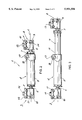
- FIG. 1 is an overall view in perspective, for an external fixation device of the invention, installed near a patient's wrist joint, and in partially expanded condition;
- FIG. 2 is a side view of the fixation device of FIG. 1, in fully retracted condition
- FIG. 3 is another side view of the fixation device of FIG. 1 in fully extended condition
- FIG. 4 is a side view of the inner one of two telescopically related central-body parts of the device of FIGS. 1 to 3, with end detail in partial longitudinal section for a bone-screw clamp connected to one end of said inner part;
- FIG. 5 is a similar side view of the other of said central body parts, with end detail in partial longitudinal section for another bone-screw clamp connected to the opposite end of said other part;
- FIG. 6 is a cross section, taken at VI--VI of FIG. 4;
- FIG. 7 is a cross section, taken at VII--VII of FIG. 5;
- FIG. 8 is a cross section, taken at VIII--VIII of FIG. 5;
- FIG. 9 is a fragmentary exploded view, and in partial section, through one of the bone-screw clamps and its connection to one of the central-body parts of the device of FIGS. 1 to 3;
- FIG. 10 is a perspective view of one of the parts of releasably lockable connection of the clamp of FIG. 9 to the central-body part of FIG. 9.
- an external axial-fixation device of the invention is indicated generally by reference numeral 1.
- the device comprises a pair of clamps 2, 3 for clamping bone screws or pins V that have previously been surgically inserted in stumps of a fracture, for example, of a wrist joint.
- the clamps 2, 3 are attached by end joints 5, 6 to the respective longitudinal ends of an extendable central body 4.
- the central body 4 can be formed of two elements, a male or inner element 7 and a female or outer element 8, of approximately cylindrical shape and circular cross section;
- the elements 7, 8 are telescopically related so that they can slide one within the other along a common longitudinal axis L, thereby varying the total length of the central body 4.
- the clamps 2, 3 are preferably formed of main body portions 9, 10 respectively, of approximately prismatic or parallelopiped shape, connected to corresponding clamp plates 11, 12 by screws 13, 14, for clamped engagement to the bone pins V.
- the telescopic elements 7, 8 are at least partially radiotransparent in order to permit radioscopy of the fracture through the central body 4.
- At least one of the telescopic elements, in particular the male or inner element 7, is made of a material of high radiotransparency.
- the material of high radiotransparency may be a thermoplastic resin of amorphous or semicrystalline structure, selected from among the polyethers, polysulfonates, polyoxymethylenes and polyetherimides.
- the female or outer telescopic element 8 is preferably made of a substantially radiopaque material, for example, an aluminum alloy, and has side walls of such slight thickness as to be at least partially radiotransparent, while also providing adequate mechanical strength.
- the male (inner) telescopic element 7 has an elongate flat 15 which extends over almost its entire length while leaving a projecting lip 16 at its distal end.
- the female element 8 has, at its distal or free end, longitudinally opposite the clamp 3, a local laterally outward projection or ear 17, which has a cut slit 19 in a radial plane that extends longitudinally at least for the longitudinal dimension of projection 17, thereby defining two confronting ear formations 17', 17" at a locally slit distal-end region of the outer body part 8, as best seen in FIG. 8.
- a transverse bore 18 (FIG. 5) through the ear formations 17', 17" is seen in FIG.
- the slit or cut 19 will be understood to be of sufficient axial extent to provide a degree of local radial or circumferential resilience at the distal end of the outer-body part 8.
- the bolt 18' which engages ear formation 17', via ear formation 17", can therefore clamp the end of the outer element 8, locking the inner element 7 in a desired position.
- bolt 18' will be seen to provide a stop at interfering abutment with lip 16, thus preventing a unintended separation of body parts 7, 8 from each other.
- main prismatic or body portions 9, 10 of each of the clamps 2, 3 have continuous cylindrical cavities 20, 21, each with its own inwardly formed spherical restriction or lip 22, 23 for engaged-ball retention.
- ball 24 of FIG. 1 illustratively for the ball 24 of FIG.
- the ball diameter should have running clearance with the bore 20 and should exceed the inner diameter of the inward lip formation 22, (ii) the ball 24 is preferably of one piece, with its mounting stem 24' pinned at 26 to the proximal end of inner-body part 7, and (iii) the truncated frustoconical base, which provides a circumferentially continuous radial shoulder for abutment reference to the flat end surface of part 7, should be of outer diameter (less than ball diameter) that is sized to enable its assembling passage through the inward lip 22 at the end of the bore 20.
- the bore 20, lip 22, and the stem 24' for mounting ball 24--all for ball-joint connection to inner-body part 7-- will be understood to have corresponding features at bore 21, lip 23, and ball 25 (with its stem 25') for ball-joint connection to outer-body part 8.
- Each of the cylindrical cavities 20, 21 accommodates a thrust slide (28, 29) having an outer cylindrical surface, of diameter to establish an axially guided running fit to the bore diameter of the cavity (20, 21), within which it is captive.
- a first end (30, 31) of each thrust slide (28, 29) is spherically concave for ball-seating engagement, and a second end (32, 33) of each thrust bushing is cylindrically concave on a diametrically extending axis that is normal to the longitudinal axis of its guidance cavity (20, 21).
- closure of each cavity is completed by a transverse pin or rotary cam (34, 35) having an eccentric portion for engagement with the cylindrically concave end of its adjacent bushing.
- transverse pin 34 in clamp body 9 will be understood from the transverse-journalling bore 34' in FIG. 9, and the eccentric throw ⁇ of the body of pin 34 will be understood from the schematic designation 34" shown in FIG. 9 for pin 34.
- a simple rotary manipulation of an Allen-head wrench to pin 34 serves for selective eccentrically driven displacement of its associated thrust slide into releasably locked retention of ball 24, for any given orientation of clamp 9 with respect to the longitudinal axis of the central body part 7 to which it is connected.
- a diametrically extending, longitudinally central bore 36 in each thrust slide is sized for sufficient clearance with possible bolt (13) thread entry, without impairing the described eccentric-driven displacement involved in releasably clamped ball engagement. Finally, bolt 18' is tightened to fix the length of the central body.
- fixation device of the invention is capable to numerous modifications and variants which fall within the scope of the accompanying claims. And the dimensions, shapes and materials may also be modified without departure from the scope of the invention.
Abstract
Description
Claims (33)
Applications Claiming Priority (2)
| Application Number | Priority Date | Filing Date | Title |
|---|---|---|---|
| ITVR96A00044 | 1996-05-15 | ||
| IT96VR000044A IT1289103B1 (en) | 1996-05-15 | 1996-05-15 | COMPACT EXTERNAL FIXER |
Publications (1)
| Publication Number | Publication Date |
|---|---|
| US5951556A true US5951556A (en) | 1999-09-14 |
Family
ID=11428190
Family Applications (1)
| Application Number | Title | Priority Date | Filing Date |
|---|---|---|---|
| US08/825,909 Expired - Lifetime US5951556A (en) | 1996-05-15 | 1997-04-02 | Compact external fixation device |
Country Status (12)
| Country | Link |
|---|---|
| US (1) | US5951556A (en) |
| EP (1) | EP0807419B1 (en) |
| JP (1) | JPH1043204A (en) |
| AR (1) | AR013567A1 (en) |
| AT (1) | ATE222078T1 (en) |
| AU (1) | AU722193B2 (en) |
| DE (1) | DE69714645T2 (en) |
| DK (1) | DK0807419T3 (en) |
| ES (1) | ES2180000T3 (en) |
| IT (1) | IT1289103B1 (en) |
| PT (1) | PT807419E (en) |
| ZA (1) | ZA974144B (en) |
Cited By (84)
| Publication number | Priority date | Publication date | Assignee | Title |
|---|---|---|---|---|
| US6409729B1 (en) | 1998-05-19 | 2002-06-25 | Synthes (Usa) | Clamp assembly for an external fixation system |
| WO2002094112A1 (en) * | 2001-05-18 | 2002-11-28 | Agenzia Spaziale Italiana | External bone-setting device |
| US6500177B1 (en) | 1998-05-19 | 2002-12-31 | Synthes (Usa) | Telescopic body for an external fixation system |
| US20030069580A1 (en) * | 2001-10-09 | 2003-04-10 | Langmaid Michael N. | Adjustable fixator |
| US20030125736A1 (en) * | 2000-05-26 | 2003-07-03 | Daniele Venturini | Axial external fixator |
| US20030139744A1 (en) * | 2000-05-26 | 2003-07-24 | Sandor Berki | Disposable external fixation device |
| US6709433B1 (en) | 2001-12-20 | 2004-03-23 | Biomet, Inc. | Bridging/non-bridging external bone fixator |
| US20040059331A1 (en) * | 2002-09-17 | 2004-03-25 | Visionmed, L.L.C. | Unilateral fixator |
| US20040097922A1 (en) * | 2002-11-14 | 2004-05-20 | Visionmed, L.L.C. | Method for a using fixator device |
| US20060064087A1 (en) * | 2004-09-03 | 2006-03-23 | Ather Mirza | External fixation device for fractures |
| US20080294173A1 (en) * | 2007-05-25 | 2008-11-27 | Reeder Jr Ralph F | Radiolucent screwdriver for orthopedic surgery |
| US20090187189A1 (en) * | 2004-09-03 | 2009-07-23 | A.M. Surgical, Inc. | External fixation device for fractures |
| US7645279B1 (en) | 2003-07-25 | 2010-01-12 | Haupt Bruce F | Bone fixation method |
| US20100063550A1 (en) * | 2008-09-11 | 2010-03-11 | Innovasis, Inc, | Radiolucent screw with radiopaque marker |
| US7731738B2 (en) | 2005-12-09 | 2010-06-08 | Orthopro, Llc | Cannulated screw |
| US20100222778A1 (en) * | 2008-09-11 | 2010-09-02 | Orthofix S.R.L. | Orthopaedic device to be associated with the outside of a bone |
| US7846162B2 (en) | 2005-05-18 | 2010-12-07 | Sonoma Orthopedic Products, Inc. | Minimally invasive actuable bone fixation devices |
| US20110060365A1 (en) * | 2009-09-10 | 2011-03-10 | Innovasis, Inc. | Radiolucent stabilizing rod with radiopaque marker |
| US7909825B2 (en) | 2006-11-22 | 2011-03-22 | Sonoma Orthepedic Products, Inc. | Fracture fixation device, tools and methods |
| US7918876B2 (en) | 2003-03-24 | 2011-04-05 | Theken Spine, Llc | Spinal implant adjustment device |
| US20110218570A1 (en) * | 2010-03-08 | 2011-09-08 | Innovasis, Inc. | Radiolucent bone plate with radiopaque marker |
| US8057473B2 (en) | 2007-10-31 | 2011-11-15 | Wright Medical Technology, Inc. | Orthopedic device |
| US8147491B2 (en) | 2007-06-27 | 2012-04-03 | Vilex In Tennessee, Inc. | Multi-angle clamp |
| US20120123301A1 (en) * | 2010-11-12 | 2012-05-17 | Connor Robert A | Spinal motion measurement device |
| US8287541B2 (en) | 2005-05-18 | 2012-10-16 | Sonoma Orthopedic Products, Inc. | Fracture fixation device, tools and methods |
| US8287538B2 (en) | 2008-01-14 | 2012-10-16 | Conventus Orthopaedics, Inc. | Apparatus and methods for fracture repair |
| US8313515B2 (en) | 2007-06-15 | 2012-11-20 | Rachiotek, Llc | Multi-level spinal stabilization system |
| US8366710B2 (en) | 2006-05-26 | 2013-02-05 | National University Corporation Nagoya University | External fixator |
| US8758343B2 (en) | 2005-04-27 | 2014-06-24 | DePuy Synthes Products, LLC | Bone fixation apparatus |
| US8864763B2 (en) | 2013-03-13 | 2014-10-21 | DePuy Synthes Products, LLC | External bone fixation device |
| US8906022B2 (en) | 2010-03-08 | 2014-12-09 | Conventus Orthopaedics, Inc. | Apparatus and methods for securing a bone implant |
| US8961516B2 (en) | 2005-05-18 | 2015-02-24 | Sonoma Orthopedic Products, Inc. | Straight intramedullary fracture fixation devices and methods |
| US8961518B2 (en) | 2010-01-20 | 2015-02-24 | Conventus Orthopaedics, Inc. | Apparatus and methods for bone access and cavity preparation |
| US9039706B2 (en) | 2013-03-13 | 2015-05-26 | DePuy Synthes Products, Inc. | External bone fixation device |
| US9060820B2 (en) | 2005-05-18 | 2015-06-23 | Sonoma Orthopedic Products, Inc. | Segmented intramedullary fracture fixation devices and methods |
| US9155574B2 (en) | 2006-05-17 | 2015-10-13 | Sonoma Orthopedic Products, Inc. | Bone fixation device, tools and methods |
| US20160015426A1 (en) * | 2014-07-15 | 2016-01-21 | Treace Medical Concepts, Inc. | Bone positioning and cutting system and method |
| US20160022315A1 (en) * | 2013-01-21 | 2016-01-28 | Tecres S.P.A. | External fixing device, for treating bone fractures |
| US9301782B2 (en) | 2012-09-04 | 2016-04-05 | Zimmer, Inc. | External fixation |
| US9468479B2 (en) | 2013-09-06 | 2016-10-18 | Cardinal Health 247, Inc. | Bone plate |
| US9642649B2 (en) | 2010-05-19 | 2017-05-09 | DePuy Synthes Products, Inc. | Orthopedic fixation with imagery analysis |
| US9675382B2 (en) | 2013-03-13 | 2017-06-13 | DePuy Synthes Products, Inc. | External bone fixation device |
| US20170209177A1 (en) * | 2014-07-25 | 2017-07-27 | The General Hospital Corporation | System and method for an external hip fixator |
| US9730739B2 (en) | 2010-01-15 | 2017-08-15 | Conventus Orthopaedics, Inc. | Rotary-rigid orthopaedic rod |
| US9770278B2 (en) | 2014-01-17 | 2017-09-26 | Arthrex, Inc. | Dual tip guide wire |
| US9814499B2 (en) | 2014-09-30 | 2017-11-14 | Arthrex, Inc. | Intramedullary fracture fixation devices and methods |
| US9924969B2 (en) | 2012-09-04 | 2018-03-27 | Zimmer, Inc. | External fixation |
| US9962187B2 (en) | 2014-08-11 | 2018-05-08 | Zimmer, Inc. | External fixation |
| US10022132B2 (en) | 2013-12-12 | 2018-07-17 | Conventus Orthopaedics, Inc. | Tissue displacement tools and methods |
| US10045807B2 (en) | 2015-08-14 | 2018-08-14 | Treace Medical Concepts, Inc. | Bone positioning and preparing guide systems and methods |
| US10342590B2 (en) | 2015-08-14 | 2019-07-09 | Treace Medical Concepts, Inc. | Tarsal-metatarsal joint procedure utilizing fulcrum |
| CN110292426A (en) * | 2019-06-25 | 2019-10-01 | 丁浩男 | A kind of external fixing rack that stress is adjustable |
| US10512470B1 (en) | 2016-08-26 | 2019-12-24 | Treace Medical Concepts, Inc. | Osteotomy procedure for correcting bone misalignment |
| WO2019245406A1 (en) * | 2018-06-21 | 2019-12-26 | Дильшад Даларисович ШАРАФИЕВ | Apparatus for external osteosynthesis |
| US10524808B1 (en) | 2016-11-11 | 2020-01-07 | Treace Medical Concepts, Inc. | Devices and techniques for performing an osteotomy procedure on a first metatarsal to correct a bone misalignment |
| US10561426B1 (en) | 2015-01-07 | 2020-02-18 | Treace Medical Concepts, Inc. | Bone cutting guide systems and methods |
| US10575862B2 (en) | 2015-09-18 | 2020-03-03 | Treace Medical Concepts, Inc. | Joint spacer systems and methods |
| CN110891495A (en) * | 2017-06-15 | 2020-03-17 | 德普伊新特斯产品公司 | SST retractor with radiolucent features |
| US10653467B2 (en) | 2015-05-06 | 2020-05-19 | Treace Medical Concepts, Inc. | Intra-osseous plate system and method |
| US10806499B2 (en) | 2017-10-10 | 2020-10-20 | Javier E. Castaneda | Universal orthopedic clamp |
| US10835318B2 (en) | 2016-08-25 | 2020-11-17 | DePuy Synthes Products, Inc. | Orthopedic fixation control and manipulation |
| US10849663B2 (en) | 2015-07-14 | 2020-12-01 | Treace Medical Concepts, Inc. | Bone cutting guide systems and methods |
| US10849631B2 (en) | 2015-02-18 | 2020-12-01 | Treace Medical Concepts, Inc. | Pivotable bone cutting guide useful for bone realignment and compression techniques |
| US10874433B2 (en) | 2017-01-30 | 2020-12-29 | Stryker European Holdings I, Llc | Strut attachments for external fixation frame |
| US10874446B2 (en) | 2015-07-14 | 2020-12-29 | Treace Medical Concepts, Inc. | Bone positioning guide |
| US10918426B2 (en) | 2017-07-04 | 2021-02-16 | Conventus Orthopaedics, Inc. | Apparatus and methods for treatment of a bone |
| US10939939B1 (en) | 2017-02-26 | 2021-03-09 | Treace Medical Concepts, Inc. | Fulcrum for tarsal-metatarsal joint procedure |
| US11134988B2 (en) | 2015-06-17 | 2021-10-05 | Zimmer, Inc. | Ankle fixation system |
| US11278337B2 (en) | 2015-08-14 | 2022-03-22 | Treace Medical Concepts, Inc. | Tarsal-metatarsal joint procedure utilizing fulcrum |
| US11304757B2 (en) | 2019-03-28 | 2022-04-19 | Synthes Gmbh | Orthopedic fixation control and visualization |
| US11334997B2 (en) | 2020-04-03 | 2022-05-17 | Synthes Gmbh | Hinge detection for orthopedic fixation |
| US11439436B2 (en) | 2019-03-18 | 2022-09-13 | Synthes Gmbh | Orthopedic fixation strut swapping |
| US11583323B2 (en) | 2018-07-12 | 2023-02-21 | Treace Medical Concepts, Inc. | Multi-diameter bone pin for installing and aligning bone fixation plate while minimizing bone damage |
| US11596443B2 (en) | 2018-07-11 | 2023-03-07 | Treace Medical Concepts, Inc. | Compressor-distractor for angularly realigning bone portions |
| US11596419B2 (en) | 2017-03-09 | 2023-03-07 | Flower Orthopedics Corporation | Plating depth gauge and countersink instrument |
| US11607250B2 (en) | 2019-02-13 | 2023-03-21 | Treace Medical Concepts, Inc. | Tarsal-metatarsal joint procedure utilizing compressor-distractor and instrument providing sliding surface |
| US11622797B2 (en) | 2020-01-31 | 2023-04-11 | Treace Medical Concepts, Inc. | Metatarsophalangeal joint preparation and metatarsal realignment for fusion |
| US11627954B2 (en) | 2019-08-07 | 2023-04-18 | Treace Medical Concepts, Inc. | Bi-planar instrument for bone cutting and joint realignment procedure |
| US11653951B2 (en) * | 2018-11-06 | 2023-05-23 | Ali Moradi | External orthopedic fixation device |
| USD1011524S1 (en) | 2022-02-23 | 2024-01-16 | Treace Medical Concepts, Inc. | Compressor-distractor for the foot |
| US11889998B1 (en) | 2019-09-12 | 2024-02-06 | Treace Medical Concepts, Inc. | Surgical pin positioning lock |
| US11890039B1 (en) | 2019-09-13 | 2024-02-06 | Treace Medical Concepts, Inc. | Multi-diameter K-wire for orthopedic applications |
| US11931106B2 (en) | 2019-09-13 | 2024-03-19 | Treace Medical Concepts, Inc. | Patient-specific surgical methods and instrumentation |
| US11950819B2 (en) | 2023-03-13 | 2024-04-09 | Treace Medical Concepts, Inc. | Bone positioning guide |
Families Citing this family (13)
| Publication number | Priority date | Publication date | Assignee | Title |
|---|---|---|---|---|
| EP1238636B1 (en) * | 2001-03-05 | 2006-08-30 | Orthofix International B.V. | External fixation device with identification means |
| KR100426565B1 (en) * | 2001-05-04 | 2004-04-08 | 메딕스얼라인 주식회사 | apparatus for adjusting an external fixator |
| US20040068263A1 (en) * | 2002-10-04 | 2004-04-08 | Benoit Chouinard | CAS bone reference with articulated support |
| JP4601664B2 (en) * | 2004-03-10 | 2010-12-22 | シンセス ゲーエムベーハー | External fixation device for joining bones |
| NZ550546A (en) * | 2004-04-19 | 2009-03-31 | Synthes Gmbh | Elastic element produced from radiolucent material for a medical device |
| NL1033925C2 (en) * | 2007-06-01 | 2008-12-02 | Umc Utrecht Holding Bv | System for correcting bones. |
| CH702239B1 (en) * | 2008-06-17 | 2011-05-31 | Kai-Uwe Lorenz | An apparatus for external fixation of bone fractures. |
| RU2485905C2 (en) * | 2011-04-05 | 2013-06-27 | Государственное образовательное учреждение высшего профессионального образования "Дагестанская государственная медицинская академия федерального агентства по здравоохранению и социальному развитию" | Device for extrafocal rod osteosynthesis of fractures of long tubular bones |
| WO2015183226A2 (en) * | 2014-05-27 | 2015-12-03 | Spi̇namer Sağlik Ürünleri̇ Sanayi̇ Ve Teknoloji̇ Li̇mi̇ted Şi̇rketi̇ | Unilateral bone fixator system enabling bone extension and three dimensional fixation |
| CN106236225B (en) * | 2014-10-24 | 2019-07-16 | 吴昊 | A kind of ring spring shape exter-nal fixer adapting to comminuted fracture |
| JP6712416B2 (en) * | 2017-04-25 | 2020-06-24 | ネオメディカル株式会社 | External fixator |
| DE102018105223A1 (en) | 2018-03-07 | 2019-09-12 | Heiko Durst | Device for external fixation of bone fractures |
| RU192266U1 (en) * | 2019-03-01 | 2019-09-11 | Константин Зорьевич Пономарев | Device for joining two pipes at an arbitrary angle |
Citations (20)
| Publication number | Priority date | Publication date | Assignee | Title |
|---|---|---|---|---|
| US31809A (en) * | 1861-03-26 | Improvement in fire-arms | ||
| US2391537A (en) * | 1943-09-27 | 1945-12-25 | Anderson Roger | Ambulatory rotating reduction and fixation splint |
| US4312336A (en) * | 1978-11-10 | 1982-01-26 | Orthofix S.R.1. | External axial fixation unit |
| US4554915A (en) * | 1983-03-08 | 1985-11-26 | Richards Medical Company | Bone fixation frame |
| US4621627A (en) * | 1984-12-18 | 1986-11-11 | Orthofix S.R.L. | External axial fixation device |
| US4643177A (en) * | 1984-06-13 | 1987-02-17 | University Of Florida | Dynamic traction wrist cast brace |
| DE3722595A1 (en) * | 1987-07-08 | 1989-01-19 | Robert Sturtzkopf | Device for the external fixation of bone fragments |
| WO1989009031A1 (en) * | 1988-03-24 | 1989-10-05 | Sheffield City Council | Bone fixation |
| NL8802463A (en) * | 1988-10-07 | 1990-05-01 | Hendrik Johan Westbroek | Bone-setting instrument - has ball-joints with plungers locked by inserted and tapped taper pins |
| WO1990007305A1 (en) * | 1989-01-04 | 1990-07-12 | Confida Sas | Bone support device |
| US4988349A (en) * | 1987-01-21 | 1991-01-29 | Orthofix S.R.L. | Device for osteosynthesis |
| US5019077A (en) * | 1989-03-17 | 1991-05-28 | Orthofix S.R.L. | External splint |
| WO1991011150A1 (en) * | 1990-01-30 | 1991-08-08 | Sheffield City Council | Bone fixation |
| WO1991011151A1 (en) * | 1990-01-30 | 1991-08-08 | Sheffield City Council | Bone fixation |
| US5292322A (en) * | 1991-11-05 | 1994-03-08 | Orthofix S.R.L. | Clamping coupling for an external fixator |
| US5304177A (en) * | 1992-06-26 | 1994-04-19 | Dietmar Pennig | Auxiliary device for osteosynthesis |
| US5320622A (en) * | 1992-07-28 | 1994-06-14 | Orthofix S.R.L. | Dynamic axial splint |
| WO1994023662A2 (en) * | 1993-04-13 | 1994-10-27 | Albert Edward Oliver | Disposable external fixator |
| US5454810A (en) * | 1990-02-05 | 1995-10-03 | Pohl; Anthony P. | External fixation device |
| US5591164A (en) * | 1994-12-22 | 1997-01-07 | Zimmer, Inc. | External fixation apparatus and system |
Family Cites Families (4)
| Publication number | Priority date | Publication date | Assignee | Title |
|---|---|---|---|---|
| GB2255284A (en) * | 1988-08-01 | 1992-11-04 | Univ Bristol | External fixator |
| FR2667781B1 (en) * | 1990-10-12 | 1994-01-21 | Materiel Orthopedique Cie Gle | EXTERNAL FIXATION AND REDUCTION OF BONE FRACTURES. |
| PL169633B1 (en) * | 1992-09-15 | 1996-08-30 | Jaroslaw Deszczynski | Dynamical compensating stabilizer |
| DE9319433U1 (en) * | 1993-12-17 | 1994-02-10 | Reckert Lothar | Unilateral fixator |
-
1996
- 1996-05-15 IT IT96VR000044A patent/IT1289103B1/en active IP Right Grant
-
1997
- 1997-04-02 US US08/825,909 patent/US5951556A/en not_active Expired - Lifetime
- 1997-05-06 AU AU20074/97A patent/AU722193B2/en not_active Ceased
- 1997-05-13 ES ES97201442T patent/ES2180000T3/en not_active Expired - Lifetime
- 1997-05-13 AT AT97201442T patent/ATE222078T1/en active
- 1997-05-13 DK DK97201442T patent/DK0807419T3/en active
- 1997-05-13 PT PT97201442T patent/PT807419E/en unknown
- 1997-05-13 EP EP97201442A patent/EP0807419B1/en not_active Expired - Lifetime
- 1997-05-13 DE DE69714645T patent/DE69714645T2/en not_active Expired - Lifetime
- 1997-05-14 JP JP9122724A patent/JPH1043204A/en active Pending
- 1997-05-14 ZA ZA9704144A patent/ZA974144B/en unknown
- 1997-05-15 AR ARP970102040A patent/AR013567A1/en active IP Right Grant
Patent Citations (22)
| Publication number | Priority date | Publication date | Assignee | Title |
|---|---|---|---|---|
| US31809A (en) * | 1861-03-26 | Improvement in fire-arms | ||
| US2391537A (en) * | 1943-09-27 | 1945-12-25 | Anderson Roger | Ambulatory rotating reduction and fixation splint |
| US4312336A (en) * | 1978-11-10 | 1982-01-26 | Orthofix S.R.1. | External axial fixation unit |
| EP0011258B1 (en) * | 1978-11-10 | 1983-01-26 | ORTHOFIX S.r.l. | Device for the external fixation of the fragments of a broken bone |
| US4554915A (en) * | 1983-03-08 | 1985-11-26 | Richards Medical Company | Bone fixation frame |
| US4643177A (en) * | 1984-06-13 | 1987-02-17 | University Of Florida | Dynamic traction wrist cast brace |
| US4621627A (en) * | 1984-12-18 | 1986-11-11 | Orthofix S.R.L. | External axial fixation device |
| US4988349A (en) * | 1987-01-21 | 1991-01-29 | Orthofix S.R.L. | Device for osteosynthesis |
| DE3722595A1 (en) * | 1987-07-08 | 1989-01-19 | Robert Sturtzkopf | Device for the external fixation of bone fragments |
| WO1989009031A1 (en) * | 1988-03-24 | 1989-10-05 | Sheffield City Council | Bone fixation |
| NL8802463A (en) * | 1988-10-07 | 1990-05-01 | Hendrik Johan Westbroek | Bone-setting instrument - has ball-joints with plungers locked by inserted and tapped taper pins |
| WO1990007305A1 (en) * | 1989-01-04 | 1990-07-12 | Confida Sas | Bone support device |
| US5019077A (en) * | 1989-03-17 | 1991-05-28 | Orthofix S.R.L. | External splint |
| WO1991011150A1 (en) * | 1990-01-30 | 1991-08-08 | Sheffield City Council | Bone fixation |
| WO1991011151A1 (en) * | 1990-01-30 | 1991-08-08 | Sheffield City Council | Bone fixation |
| US5454810A (en) * | 1990-02-05 | 1995-10-03 | Pohl; Anthony P. | External fixation device |
| US5292322A (en) * | 1991-11-05 | 1994-03-08 | Orthofix S.R.L. | Clamping coupling for an external fixator |
| US5342360A (en) * | 1991-11-05 | 1994-08-30 | Orthofix S.R.L. | Clamping coupling for an external fixator |
| US5304177A (en) * | 1992-06-26 | 1994-04-19 | Dietmar Pennig | Auxiliary device for osteosynthesis |
| US5320622A (en) * | 1992-07-28 | 1994-06-14 | Orthofix S.R.L. | Dynamic axial splint |
| WO1994023662A2 (en) * | 1993-04-13 | 1994-10-27 | Albert Edward Oliver | Disposable external fixator |
| US5591164A (en) * | 1994-12-22 | 1997-01-07 | Zimmer, Inc. | External fixation apparatus and system |
Non-Patent Citations (2)
| Title |
|---|
| Orthofix Srl., Orthofix The Pennig Dynamic Wrist Fixator, Operative Technique , Mar. 25, 1993, 47 pages. * |
| Orthofix Srl.,"Orthofix® The Pennig Dynamic Wrist Fixator, Operative Technique", Mar. 25, 1993, 47 pages. |
Cited By (167)
| Publication number | Priority date | Publication date | Assignee | Title |
|---|---|---|---|---|
| US6409729B1 (en) | 1998-05-19 | 2002-06-25 | Synthes (Usa) | Clamp assembly for an external fixation system |
| US6500177B1 (en) | 1998-05-19 | 2002-12-31 | Synthes (Usa) | Telescopic body for an external fixation system |
| US7147639B2 (en) * | 2000-05-26 | 2006-12-12 | Orthofix S.R.L. | Disposable external fixation device |
| US20030125736A1 (en) * | 2000-05-26 | 2003-07-03 | Daniele Venturini | Axial external fixator |
| US20030139744A1 (en) * | 2000-05-26 | 2003-07-24 | Sandor Berki | Disposable external fixation device |
| US6840939B2 (en) * | 2000-05-26 | 2005-01-11 | Orthofix S.R.L. | Axial external fixator |
| WO2002094112A1 (en) * | 2001-05-18 | 2002-11-28 | Agenzia Spaziale Italiana | External bone-setting device |
| US20030069580A1 (en) * | 2001-10-09 | 2003-04-10 | Langmaid Michael N. | Adjustable fixator |
| US8382757B1 (en) | 2001-10-09 | 2013-02-26 | Synthes Usa, Llc | Adjustable fixator |
| US7261713B2 (en) | 2001-10-09 | 2007-08-28 | Synthes (Usa) | Adjustable fixator |
| US6709433B1 (en) | 2001-12-20 | 2004-03-23 | Biomet, Inc. | Bridging/non-bridging external bone fixator |
| US20040059331A1 (en) * | 2002-09-17 | 2004-03-25 | Visionmed, L.L.C. | Unilateral fixator |
| US8388619B2 (en) | 2002-09-17 | 2013-03-05 | Sixfix Inc. | Unilateral fixator |
| US7282052B2 (en) | 2002-09-17 | 2007-10-16 | Ebi, L.P. | Unilateral fixator |
| US20070282338A1 (en) * | 2002-09-17 | 2007-12-06 | Ebi, L.P. | Unilateral fixator |
| US8419732B2 (en) | 2002-11-14 | 2013-04-16 | Sixfix, Inc. | Method for using a fixator device |
| US20040097922A1 (en) * | 2002-11-14 | 2004-05-20 | Visionmed, L.L.C. | Method for a using fixator device |
| US20110103676A1 (en) * | 2002-11-14 | 2011-05-05 | Extraortho, Inc. | Method for using a fixator device |
| US7918876B2 (en) | 2003-03-24 | 2011-04-05 | Theken Spine, Llc | Spinal implant adjustment device |
| US7645279B1 (en) | 2003-07-25 | 2010-01-12 | Haupt Bruce F | Bone fixation method |
| US8518039B2 (en) | 2004-09-03 | 2013-08-27 | A.M. Surgical, Inc. | External fixation device for fractures |
| US20060064087A1 (en) * | 2004-09-03 | 2006-03-23 | Ather Mirza | External fixation device for fractures |
| US8262656B2 (en) | 2004-09-03 | 2012-09-11 | A.M. Surgical, Inc. | External fixation device for fractures |
| US20090187189A1 (en) * | 2004-09-03 | 2009-07-23 | A.M. Surgical, Inc. | External fixation device for fractures |
| US7828801B2 (en) | 2004-09-03 | 2010-11-09 | A.M. Surgical, Inc. | External fixation device for fractures |
| US8758343B2 (en) | 2005-04-27 | 2014-06-24 | DePuy Synthes Products, LLC | Bone fixation apparatus |
| US8287541B2 (en) | 2005-05-18 | 2012-10-16 | Sonoma Orthopedic Products, Inc. | Fracture fixation device, tools and methods |
| US7942875B2 (en) | 2005-05-18 | 2011-05-17 | Sonoma Orthopedic Products, Inc. | Methods of using minimally invasive actuable bone fixation devices |
| US8961516B2 (en) | 2005-05-18 | 2015-02-24 | Sonoma Orthopedic Products, Inc. | Straight intramedullary fracture fixation devices and methods |
| US7914533B2 (en) | 2005-05-18 | 2011-03-29 | Sonoma Orthopedic Products, Inc. | Minimally invasive actuable bone fixation devices |
| US8287539B2 (en) | 2005-05-18 | 2012-10-16 | Sonoma Orthopedic Products, Inc. | Fracture fixation device, tools and methods |
| US9060820B2 (en) | 2005-05-18 | 2015-06-23 | Sonoma Orthopedic Products, Inc. | Segmented intramedullary fracture fixation devices and methods |
| US7846162B2 (en) | 2005-05-18 | 2010-12-07 | Sonoma Orthopedic Products, Inc. | Minimally invasive actuable bone fixation devices |
| US7731738B2 (en) | 2005-12-09 | 2010-06-08 | Orthopro, Llc | Cannulated screw |
| US9155574B2 (en) | 2006-05-17 | 2015-10-13 | Sonoma Orthopedic Products, Inc. | Bone fixation device, tools and methods |
| US8366710B2 (en) | 2006-05-26 | 2013-02-05 | National University Corporation Nagoya University | External fixator |
| US8439917B2 (en) | 2006-11-22 | 2013-05-14 | Sonoma Orthopedic Products, Inc. | Fracture fixation device, tools and methods |
| US7909825B2 (en) | 2006-11-22 | 2011-03-22 | Sonoma Orthepedic Products, Inc. | Fracture fixation device, tools and methods |
| US9259250B2 (en) | 2006-11-22 | 2016-02-16 | Sonoma Orthopedic Products, Inc. | Fracture fixation device, tools and methods |
| US7981116B2 (en) * | 2007-05-25 | 2011-07-19 | Custom Spine, Inc. | Radiolucent screwdriver for orthopedic surgery |
| US20080294173A1 (en) * | 2007-05-25 | 2008-11-27 | Reeder Jr Ralph F | Radiolucent screwdriver for orthopedic surgery |
| US8313515B2 (en) | 2007-06-15 | 2012-11-20 | Rachiotek, Llc | Multi-level spinal stabilization system |
| US8147491B2 (en) | 2007-06-27 | 2012-04-03 | Vilex In Tennessee, Inc. | Multi-angle clamp |
| US8057473B2 (en) | 2007-10-31 | 2011-11-15 | Wright Medical Technology, Inc. | Orthopedic device |
| US9492199B2 (en) | 2007-10-31 | 2016-11-15 | Wright Medical Technology, Inc. | Orthopedic device |
| US8585702B2 (en) | 2007-10-31 | 2013-11-19 | Wright Medical Technology, Inc. | Orthopedic device |
| US9084632B2 (en) | 2007-10-31 | 2015-07-21 | Wright Medical Technology, Inc. | Orthopedic device |
| US9993267B2 (en) | 2007-10-31 | 2018-06-12 | Wright Medical Technology, Inc. | Orthopedic implant |
| US9517093B2 (en) | 2008-01-14 | 2016-12-13 | Conventus Orthopaedics, Inc. | Apparatus and methods for fracture repair |
| US10603087B2 (en) | 2008-01-14 | 2020-03-31 | Conventus Orthopaedics, Inc. | Apparatus and methods for fracture repair |
| US8287538B2 (en) | 2008-01-14 | 2012-10-16 | Conventus Orthopaedics, Inc. | Apparatus and methods for fracture repair |
| US11399878B2 (en) | 2008-01-14 | 2022-08-02 | Conventus Orthopaedics, Inc. | Apparatus and methods for fracture repair |
| US9788870B2 (en) | 2008-01-14 | 2017-10-17 | Conventus Orthopaedics, Inc. | Apparatus and methods for fracture repair |
| US9408649B2 (en) * | 2008-09-11 | 2016-08-09 | Innovasis, Inc. | Radiolucent screw with radiopaque marker |
| US20110172718A1 (en) * | 2008-09-11 | 2011-07-14 | Innovasis, Inc. | Radiolucent screw with radiopaque marker |
| USRE45888E1 (en) * | 2008-09-11 | 2016-02-16 | Orthofix S.R.L. | Orthopaedic device to be associated with the outside of a bone |
| US20100222778A1 (en) * | 2008-09-11 | 2010-09-02 | Orthofix S.R.L. | Orthopaedic device to be associated with the outside of a bone |
| US10194950B2 (en) | 2008-09-11 | 2019-02-05 | Innovasis, Inc. | Radiolucent screw with radiopaque marker |
| US8182483B2 (en) * | 2008-09-11 | 2012-05-22 | Orthofix S.R.L. | Orthopaedic device to be associated with the outside of a bone |
| US20100063550A1 (en) * | 2008-09-11 | 2010-03-11 | Innovasis, Inc, | Radiolucent screw with radiopaque marker |
| US20110060365A1 (en) * | 2009-09-10 | 2011-03-10 | Innovasis, Inc. | Radiolucent stabilizing rod with radiopaque marker |
| US9433439B2 (en) | 2009-09-10 | 2016-09-06 | Innovasis, Inc. | Radiolucent stabilizing rod with radiopaque marker |
| US9730739B2 (en) | 2010-01-15 | 2017-08-15 | Conventus Orthopaedics, Inc. | Rotary-rigid orthopaedic rod |
| US8961518B2 (en) | 2010-01-20 | 2015-02-24 | Conventus Orthopaedics, Inc. | Apparatus and methods for bone access and cavity preparation |
| US9848889B2 (en) | 2010-01-20 | 2017-12-26 | Conventus Orthopaedics, Inc. | Apparatus and methods for bone access and cavity preparation |
| US9993277B2 (en) | 2010-03-08 | 2018-06-12 | Conventus Orthopaedics, Inc. | Apparatus and methods for securing a bone implant |
| US8906022B2 (en) | 2010-03-08 | 2014-12-09 | Conventus Orthopaedics, Inc. | Apparatus and methods for securing a bone implant |
| US20110218570A1 (en) * | 2010-03-08 | 2011-09-08 | Innovasis, Inc. | Radiolucent bone plate with radiopaque marker |
| US8801712B2 (en) | 2010-03-08 | 2014-08-12 | Innovasis, Inc. | Radiolucent bone plate with radiopaque marker |
| US10932857B2 (en) | 2010-05-19 | 2021-03-02 | DePuy Synthes Products, Inc. | Orthopedic fixation with imagery analysis |
| US9642649B2 (en) | 2010-05-19 | 2017-05-09 | DePuy Synthes Products, Inc. | Orthopedic fixation with imagery analysis |
| US11896313B2 (en) | 2010-05-19 | 2024-02-13 | DePuy Synthes Products, Inc. | Orthopedic fixation with imagery analysis |
| US20120123301A1 (en) * | 2010-11-12 | 2012-05-17 | Connor Robert A | Spinal motion measurement device |
| US8721566B2 (en) * | 2010-11-12 | 2014-05-13 | Robert A. Connor | Spinal motion measurement device |
| US10433873B2 (en) | 2012-09-04 | 2019-10-08 | Zimmer, Inc. | External fixation |
| US9924969B2 (en) | 2012-09-04 | 2018-03-27 | Zimmer, Inc. | External fixation |
| US10010348B2 (en) | 2012-09-04 | 2018-07-03 | Zimmer, Inc. | External fixation |
| US9301782B2 (en) | 2012-09-04 | 2016-04-05 | Zimmer, Inc. | External fixation |
| US10905469B2 (en) | 2012-09-04 | 2021-02-02 | Zimmer, Inc. | External fixation |
| US9750538B2 (en) * | 2013-01-21 | 2017-09-05 | Tecres S.P.A. | External fixing device, for treating bone fractures |
| AU2014206484B2 (en) * | 2013-01-21 | 2018-05-10 | Tecres S.P.A. | External fixing device, for treating bone fractures |
| US20160022315A1 (en) * | 2013-01-21 | 2016-01-28 | Tecres S.P.A. | External fixing device, for treating bone fractures |
| US8864763B2 (en) | 2013-03-13 | 2014-10-21 | DePuy Synthes Products, LLC | External bone fixation device |
| US9039706B2 (en) | 2013-03-13 | 2015-05-26 | DePuy Synthes Products, Inc. | External bone fixation device |
| US9675382B2 (en) | 2013-03-13 | 2017-06-13 | DePuy Synthes Products, Inc. | External bone fixation device |
| US9788861B2 (en) | 2013-03-13 | 2017-10-17 | DePuy Synthes Products, Inc. | External bone fixation device |
| US10470800B2 (en) | 2013-03-13 | 2019-11-12 | DePuy Synthes Products, Inc. | External bone fixation device |
| US9468479B2 (en) | 2013-09-06 | 2016-10-18 | Cardinal Health 247, Inc. | Bone plate |
| US10022132B2 (en) | 2013-12-12 | 2018-07-17 | Conventus Orthopaedics, Inc. | Tissue displacement tools and methods |
| US10076342B2 (en) | 2013-12-12 | 2018-09-18 | Conventus Orthopaedics, Inc. | Tissue displacement tools and methods |
| US9770278B2 (en) | 2014-01-17 | 2017-09-26 | Arthrex, Inc. | Dual tip guide wire |
| US11771467B2 (en) | 2014-07-15 | 2023-10-03 | Treace Medical Concepts, Inc. | Bone positioning and cutting system and method |
| US11523845B2 (en) | 2014-07-15 | 2022-12-13 | Treace Medical Concepts, Inc. | Bone positioning and cutting system and method |
| US10945764B2 (en) | 2014-07-15 | 2021-03-16 | Treace Medical Concepts, Inc. | Bone positioning and cutting system and method |
| US11147590B2 (en) | 2014-07-15 | 2021-10-19 | Treace Medical Concepts, Inc. | Bone positioning and cutting system and method |
| US11937849B2 (en) | 2014-07-15 | 2024-03-26 | Treace Medical Concepts, Inc. | Bone positioning and cutting system and method |
| US10555757B2 (en) | 2014-07-15 | 2020-02-11 | Treace Medical Concepts, Inc. | Bone positioning and cutting system and method |
| US20160015426A1 (en) * | 2014-07-15 | 2016-01-21 | Treace Medical Concepts, Inc. | Bone positioning and cutting system and method |
| US11497528B2 (en) | 2014-07-15 | 2022-11-15 | Treace Medical Concepts, Inc. | Bone positioning and cutting system and method |
| US10314618B2 (en) * | 2014-07-25 | 2019-06-11 | The General Hospital Corporation | System and method for an external hip fixator |
| US20170209177A1 (en) * | 2014-07-25 | 2017-07-27 | The General Hospital Corporation | System and method for an external hip fixator |
| US9962187B2 (en) | 2014-08-11 | 2018-05-08 | Zimmer, Inc. | External fixation |
| US10543019B2 (en) | 2014-08-11 | 2020-01-28 | Zimmer, Inc. | External fixation |
| US10548648B2 (en) | 2014-09-30 | 2020-02-04 | Arthrex, Inc. | Intramedullary fracture fixation devices and methods |
| US9814499B2 (en) | 2014-09-30 | 2017-11-14 | Arthrex, Inc. | Intramedullary fracture fixation devices and methods |
| US10888335B2 (en) | 2015-01-07 | 2021-01-12 | Treace Medical Concepts, Inc. | Bone cutting guide systems and methods |
| US10561426B1 (en) | 2015-01-07 | 2020-02-18 | Treace Medical Concepts, Inc. | Bone cutting guide systems and methods |
| US10603046B2 (en) | 2015-01-07 | 2020-03-31 | Treace Medical Concepts, Inc. | Bone cutting guide systems and methods |
| US11786257B2 (en) | 2015-01-07 | 2023-10-17 | Treace Medical Concepts, Inc. | Bone cutting guide systems and methods |
| US10849631B2 (en) | 2015-02-18 | 2020-12-01 | Treace Medical Concepts, Inc. | Pivotable bone cutting guide useful for bone realignment and compression techniques |
| US11844533B2 (en) | 2015-02-18 | 2023-12-19 | Treace Medical Concepts, Inc. | Pivotable bone cutting guide useful for bone realignment and compression techniques |
| US10653467B2 (en) | 2015-05-06 | 2020-05-19 | Treace Medical Concepts, Inc. | Intra-osseous plate system and method |
| US11426219B2 (en) | 2015-05-06 | 2022-08-30 | Treace Medical Concepts, Inc. | Intra-osseous plate system and method |
| US11134988B2 (en) | 2015-06-17 | 2021-10-05 | Zimmer, Inc. | Ankle fixation system |
| US11185359B2 (en) | 2015-07-14 | 2021-11-30 | Treace Medical Concepts, Inc. | Bone positioning guide |
| US10874446B2 (en) | 2015-07-14 | 2020-12-29 | Treace Medical Concepts, Inc. | Bone positioning guide |
| US10335220B2 (en) | 2015-07-14 | 2019-07-02 | Treace Medical Concepts, Inc. | Bone positioning guide |
| US11602386B2 (en) | 2015-07-14 | 2023-03-14 | Treace Medical Concepts, Inc. | Bone positioning guide |
| US10849663B2 (en) | 2015-07-14 | 2020-12-01 | Treace Medical Concepts, Inc. | Bone cutting guide systems and methods |
| US11116558B2 (en) | 2015-07-14 | 2021-09-14 | Treace Medical Concepts, Inc. | Bone positioning guide |
| US10342590B2 (en) | 2015-08-14 | 2019-07-09 | Treace Medical Concepts, Inc. | Tarsal-metatarsal joint procedure utilizing fulcrum |
| US11413081B2 (en) | 2015-08-14 | 2022-08-16 | Treace Medical Concepts, Inc. | Tarsal-metatarsal joint procedure utilizing fulcrum |
| US11690659B2 (en) | 2015-08-14 | 2023-07-04 | Treace Medical Concepts, Inc. | Tarsal-metatarsal joint procedure utilizing fulcrum |
| US11602387B2 (en) | 2015-08-14 | 2023-03-14 | Treace Medical Concepts, Inc. | Bone positioning and preparing guide systems and methods |
| US10045807B2 (en) | 2015-08-14 | 2018-08-14 | Treace Medical Concepts, Inc. | Bone positioning and preparing guide systems and methods |
| US11039873B2 (en) | 2015-08-14 | 2021-06-22 | Treace Medical Concepts, Inc. | Bone positioning and preparing guide systems and methods |
| US10849670B2 (en) | 2015-08-14 | 2020-12-01 | Treace Medical Concepts, Inc. | Bone positioning and preparing guide systems and methods |
| US11213333B2 (en) | 2015-08-14 | 2022-01-04 | Treace Medical Concepts, Inc. | Bone positioning and preparing guide systems and methods |
| US11278337B2 (en) | 2015-08-14 | 2022-03-22 | Treace Medical Concepts, Inc. | Tarsal-metatarsal joint procedure utilizing fulcrum |
| US11911085B2 (en) | 2015-08-14 | 2024-02-27 | Treace Medical Concepts, Inc. | Bone positioning and preparing guide systems and methods |
| US11771443B2 (en) | 2015-09-18 | 2023-10-03 | Treace Medical Concepts, Inc. | Joint spacer systems and methods |
| US11648019B2 (en) | 2015-09-18 | 2023-05-16 | Treace Medical Concepts, Inc. | Joint spacer systems and methods |
| US10575862B2 (en) | 2015-09-18 | 2020-03-03 | Treace Medical Concepts, Inc. | Joint spacer systems and methods |
| US10835318B2 (en) | 2016-08-25 | 2020-11-17 | DePuy Synthes Products, Inc. | Orthopedic fixation control and manipulation |
| US11918292B2 (en) | 2016-08-25 | 2024-03-05 | DePuy Synthes Products, Inc. | Orthopedic fixation control and manipulation |
| US11076863B1 (en) | 2016-08-26 | 2021-08-03 | Treace Medical Concepts, Inc. | Osteotomy procedure for correcting bone misalignment |
| US11931047B2 (en) | 2016-08-26 | 2024-03-19 | Treace Medical Concepts, Inc. | Osteotomy procedure for correcting bone misalignment |
| US10512470B1 (en) | 2016-08-26 | 2019-12-24 | Treace Medical Concepts, Inc. | Osteotomy procedure for correcting bone misalignment |
| US10524808B1 (en) | 2016-11-11 | 2020-01-07 | Treace Medical Concepts, Inc. | Devices and techniques for performing an osteotomy procedure on a first metatarsal to correct a bone misalignment |
| US10582936B1 (en) | 2016-11-11 | 2020-03-10 | Treace Medical Concepts, Inc. | Devices and techniques for performing an osteotomy procedure on a first metatarsal to correct a bone misalignment |
| US11364037B2 (en) | 2016-11-11 | 2022-06-21 | Treace Medical Concepts, Inc. | Techniques for performing an osteotomy procedure on bone to correct a bone misalignment |
| US10874433B2 (en) | 2017-01-30 | 2020-12-29 | Stryker European Holdings I, Llc | Strut attachments for external fixation frame |
| US11723690B2 (en) | 2017-01-30 | 2023-08-15 | Stryker European Operations Holdings Llc | Strut attachments for external fixation frame |
| US10939939B1 (en) | 2017-02-26 | 2021-03-09 | Treace Medical Concepts, Inc. | Fulcrum for tarsal-metatarsal joint procedure |
| US11596419B2 (en) | 2017-03-09 | 2023-03-07 | Flower Orthopedics Corporation | Plating depth gauge and countersink instrument |
| CN110891495B (en) * | 2017-06-15 | 2023-10-27 | 德普伊新特斯产品公司 | SST retractor with radiolucent features |
| CN110891495A (en) * | 2017-06-15 | 2020-03-17 | 德普伊新特斯产品公司 | SST retractor with radiolucent features |
| US10918426B2 (en) | 2017-07-04 | 2021-02-16 | Conventus Orthopaedics, Inc. | Apparatus and methods for treatment of a bone |
| US10806499B2 (en) | 2017-10-10 | 2020-10-20 | Javier E. Castaneda | Universal orthopedic clamp |
| WO2019245406A1 (en) * | 2018-06-21 | 2019-12-26 | Дильшад Даларисович ШАРАФИЕВ | Apparatus for external osteosynthesis |
| US11596443B2 (en) | 2018-07-11 | 2023-03-07 | Treace Medical Concepts, Inc. | Compressor-distractor for angularly realigning bone portions |
| US11583323B2 (en) | 2018-07-12 | 2023-02-21 | Treace Medical Concepts, Inc. | Multi-diameter bone pin for installing and aligning bone fixation plate while minimizing bone damage |
| US11653951B2 (en) * | 2018-11-06 | 2023-05-23 | Ali Moradi | External orthopedic fixation device |
| US11607250B2 (en) | 2019-02-13 | 2023-03-21 | Treace Medical Concepts, Inc. | Tarsal-metatarsal joint procedure utilizing compressor-distractor and instrument providing sliding surface |
| US11648035B2 (en) | 2019-03-18 | 2023-05-16 | Synthes Gmbh | Orthopedic fixation strut swapping |
| US11439436B2 (en) | 2019-03-18 | 2022-09-13 | Synthes Gmbh | Orthopedic fixation strut swapping |
| US11304757B2 (en) | 2019-03-28 | 2022-04-19 | Synthes Gmbh | Orthopedic fixation control and visualization |
| CN110292426A (en) * | 2019-06-25 | 2019-10-01 | 丁浩男 | A kind of external fixing rack that stress is adjustable |
| US11627954B2 (en) | 2019-08-07 | 2023-04-18 | Treace Medical Concepts, Inc. | Bi-planar instrument for bone cutting and joint realignment procedure |
| US11889998B1 (en) | 2019-09-12 | 2024-02-06 | Treace Medical Concepts, Inc. | Surgical pin positioning lock |
| US11890039B1 (en) | 2019-09-13 | 2024-02-06 | Treace Medical Concepts, Inc. | Multi-diameter K-wire for orthopedic applications |
| US11931106B2 (en) | 2019-09-13 | 2024-03-19 | Treace Medical Concepts, Inc. | Patient-specific surgical methods and instrumentation |
| US11622797B2 (en) | 2020-01-31 | 2023-04-11 | Treace Medical Concepts, Inc. | Metatarsophalangeal joint preparation and metatarsal realignment for fusion |
| US11893737B2 (en) | 2020-04-03 | 2024-02-06 | Synthes Gmbh | Hinge detection for orthopedic fixation |
| US11334997B2 (en) | 2020-04-03 | 2022-05-17 | Synthes Gmbh | Hinge detection for orthopedic fixation |
| USD1011524S1 (en) | 2022-02-23 | 2024-01-16 | Treace Medical Concepts, Inc. | Compressor-distractor for the foot |
| US11950819B2 (en) | 2023-03-13 | 2024-04-09 | Treace Medical Concepts, Inc. | Bone positioning guide |
Also Published As
| Publication number | Publication date |
|---|---|
| ZA974144B (en) | 1997-12-09 |
| DE69714645T2 (en) | 2003-04-24 |
| IT1289103B1 (en) | 1998-09-25 |
| ATE222078T1 (en) | 2002-08-15 |
| AU2007497A (en) | 1997-11-20 |
| AR013567A1 (en) | 2001-01-10 |
| EP0807419B1 (en) | 2002-08-14 |
| ITVR960044A0 (en) | 1996-05-15 |
| EP0807419A2 (en) | 1997-11-19 |
| EP0807419A3 (en) | 1998-04-08 |
| MX9703557A (en) | 1998-06-30 |
| ITVR960044A1 (en) | 1997-11-15 |
| PT807419E (en) | 2002-11-29 |
| ES2180000T3 (en) | 2003-02-01 |
| DE69714645D1 (en) | 2002-09-19 |
| JPH1043204A (en) | 1998-02-17 |
| AU722193B2 (en) | 2000-07-27 |
| DK0807419T3 (en) | 2002-10-07 |
Similar Documents
| Publication | Publication Date | Title |
|---|---|---|
| US5951556A (en) | Compact external fixation device | |
| JP3056257B2 (en) | External splint for femoral trochanter | |
| US9788861B2 (en) | External bone fixation device | |
| CA2057440C (en) | Two-part angle plate | |
| US5108398A (en) | Orthopaedic knee fusion apparatus | |
| US4127119A (en) | Fracture reducing and joint immobilizing apparatus | |
| AU2002309801B2 (en) | Fermoral nail intamedullary system | |
| US8864763B2 (en) | External bone fixation device | |
| US5112333A (en) | Intramedullary nail | |
| US5575791A (en) | Universal eccentric fixation mechanism for orthopedic surgery | |
| US4919119A (en) | External dynamic bone fixation device | |
| US20070123856A1 (en) | Trauma joint, external fixator and associated method | |
| US5320623A (en) | Clamping coupling for an external fixator | |
| US20070123857A1 (en) | Orthopaedic joint, device and associated method | |
| US5454810A (en) | External fixation device | |
| US5984970A (en) | Arthroplasty joint assembly | |
| US20070100338A1 (en) | Orthopaedic instrument joint, instrument and associated method | |
| US20130325007A1 (en) | Segmented intramedullary implant | |
| EP1779790A2 (en) | Support for locating instrument guides | |
| JP2001511038A (en) | Hip prosthesis and fitting method | |
| JP2008500844A (en) | Method for treating femoral fracture and device for femoral fracture | |
| US10258378B2 (en) | External bone fixation system | |
| US20070288016A1 (en) | Bone support | |
| US9173664B2 (en) | Intramedullary nail holding device | |
| WO1994023662A2 (en) | Disposable external fixator |
Legal Events
| Date | Code | Title | Description |
|---|---|---|---|
| AS | Assignment |
Owner name: ORTHOFIX S.R.L., ITALY Free format text: ASSIGNMENT OF ASSIGNORS INTEREST;ASSIGNORS:FACCIOLI, GIOVANNI;VENTURINI, DANIELE;NELSON, DAVID;REEL/FRAME:008474/0189;SIGNING DATES FROM 19970325 TO 19970401 |
|
| STCF | Information on status: patent grant |
Free format text: PATENTED CASE |
|
| FPAY | Fee payment |
Year of fee payment: 4 |
|
| AS | Assignment |
Owner name: ORTHOFIX INTERNATIONAL B.V., NETHERLANDS Free format text: ASSIGNMENT OF ASSIGNORS INTEREST;ASSIGNOR:ORTHOFIX S.R.L.;REEL/FRAME:014446/0135 Effective date: 20030101 |
|
| AS | Assignment |
Owner name: ORTHOFIX S.R.L.,ITALY Free format text: ASSIGNMENT OF ASSIGNORS INTEREST;ASSIGNOR:ORTHOFIX INTERNATIONAL B.V.;REEL/FRAME:018224/0446 Effective date: 20060801 Owner name: ORTHOFIX S.R.L., ITALY Free format text: ASSIGNMENT OF ASSIGNORS INTEREST;ASSIGNOR:ORTHOFIX INTERNATIONAL B.V.;REEL/FRAME:018224/0446 Effective date: 20060801 |
|
| FEPP | Fee payment procedure |
Free format text: PAT HOLDER NO LONGER CLAIMS SMALL ENTITY STATUS, ENTITY STATUS SET TO UNDISCOUNTED (ORIGINAL EVENT CODE: STOL); ENTITY STATUS OF PATENT OWNER: LARGE ENTITY |
|
| FEPP | Fee payment procedure |
Free format text: PAYOR NUMBER ASSIGNED (ORIGINAL EVENT CODE: ASPN); ENTITY STATUS OF PATENT OWNER: LARGE ENTITY Free format text: PAYER NUMBER DE-ASSIGNED (ORIGINAL EVENT CODE: RMPN); ENTITY STATUS OF PATENT OWNER: LARGE ENTITY |
|
| FPAY | Fee payment |
Year of fee payment: 8 |
|
| FPAY | Fee payment |
Year of fee payment: 12 |