US5926318A - Biocular viewing system with intermediate image planes for an electronic display device - Google Patents
Biocular viewing system with intermediate image planes for an electronic display device Download PDFInfo
- Publication number
- US5926318A US5926318A US09/056,934 US5693498A US5926318A US 5926318 A US5926318 A US 5926318A US 5693498 A US5693498 A US 5693498A US 5926318 A US5926318 A US 5926318A
- Authority
- US
- United States
- Prior art keywords
- light
- viewing system
- display device
- color
- biocular
- Prior art date
- Legal status (The legal status is an assumption and is not a legal conclusion. Google has not performed a legal analysis and makes no representation as to the accuracy of the status listed.)
- Expired - Lifetime
Links
- 230000003287 optical effect Effects 0.000 claims abstract description 147
- 238000003384 imaging method Methods 0.000 claims abstract description 60
- 230000005043 peripheral vision Effects 0.000 claims abstract description 31
- 238000012937 correction Methods 0.000 claims abstract description 27
- 238000002156 mixing Methods 0.000 claims abstract description 25
- 238000005286 illumination Methods 0.000 claims abstract description 18
- 238000000034 method Methods 0.000 claims description 50
- 239000000758 substrate Substances 0.000 claims description 12
- 239000003086 colorant Substances 0.000 claims description 9
- 230000001902 propagating effect Effects 0.000 claims description 8
- 230000000903 blocking effect Effects 0.000 claims description 6
- 239000002991 molded plastic Substances 0.000 claims description 6
- 230000002093 peripheral effect Effects 0.000 claims description 6
- 239000004973 liquid crystal related substance Substances 0.000 claims description 4
- 238000004519 manufacturing process Methods 0.000 claims description 4
- 230000004313 glare Effects 0.000 claims description 3
- 230000003213 activating effect Effects 0.000 claims 3
- 238000012544 monitoring process Methods 0.000 claims 2
- 238000010137 moulding (plastic) Methods 0.000 claims 1
- 238000005070 sampling Methods 0.000 claims 1
- 230000000087 stabilizing effect Effects 0.000 claims 1
- 230000009977 dual effect Effects 0.000 abstract description 7
- 239000004033 plastic Substances 0.000 abstract description 6
- 238000010276 construction Methods 0.000 abstract description 3
- 238000012545 processing Methods 0.000 description 13
- 238000013461 design Methods 0.000 description 10
- 230000006870 function Effects 0.000 description 9
- 230000005540 biological transmission Effects 0.000 description 8
- 238000012163 sequencing technique Methods 0.000 description 8
- 238000010586 diagram Methods 0.000 description 6
- 230000004308 accommodation Effects 0.000 description 5
- 238000013459 approach Methods 0.000 description 5
- 230000008447 perception Effects 0.000 description 5
- 230000000007 visual effect Effects 0.000 description 4
- 230000000694 effects Effects 0.000 description 3
- 238000001914 filtration Methods 0.000 description 3
- PPBRXRYQALVLMV-UHFFFAOYSA-N Styrene Chemical compound C=CC1=CC=CC=C1 PPBRXRYQALVLMV-UHFFFAOYSA-N 0.000 description 2
- 230000004913 activation Effects 0.000 description 2
- 230000004075 alteration Effects 0.000 description 2
- 238000006243 chemical reaction Methods 0.000 description 2
- 230000004438 eyesight Effects 0.000 description 2
- 230000007774 longterm Effects 0.000 description 2
- 239000000463 material Substances 0.000 description 2
- 238000003860 storage Methods 0.000 description 2
- 239000004677 Nylon Substances 0.000 description 1
- NIXOWILDQLNWCW-UHFFFAOYSA-N acrylic acid group Chemical group C(C=C)(=O)O NIXOWILDQLNWCW-UHFFFAOYSA-N 0.000 description 1
- 230000000747 cardiac effect Effects 0.000 description 1
- 238000005266 casting Methods 0.000 description 1
- 238000000576 coating method Methods 0.000 description 1
- 230000001427 coherent effect Effects 0.000 description 1
- 238000004883 computer application Methods 0.000 description 1
- 239000012141 concentrate Substances 0.000 description 1
- 210000004351 coronary vessel Anatomy 0.000 description 1
- 230000003247 decreasing effect Effects 0.000 description 1
- 239000006185 dispersion Substances 0.000 description 1
- 238000006073 displacement reaction Methods 0.000 description 1
- 238000005323 electroforming Methods 0.000 description 1
- 238000005516 engineering process Methods 0.000 description 1
- 238000002347 injection Methods 0.000 description 1
- 239000007924 injection Substances 0.000 description 1
- 238000009434 installation Methods 0.000 description 1
- 230000010354 integration Effects 0.000 description 1
- VMPHSYLJUKZBJJ-UHFFFAOYSA-N lauric acid triglyceride Natural products CCCCCCCCCCCC(=O)OCC(OC(=O)CCCCCCCCCCC)COC(=O)CCCCCCCCCCC VMPHSYLJUKZBJJ-UHFFFAOYSA-N 0.000 description 1
- 238000003754 machining Methods 0.000 description 1
- 238000003801 milling Methods 0.000 description 1
- 238000002324 minimally invasive surgery Methods 0.000 description 1
- 238000012978 minimally invasive surgical procedure Methods 0.000 description 1
- 238000000465 moulding Methods 0.000 description 1
- 229920001778 nylon Polymers 0.000 description 1
- 230000000399 orthopedic effect Effects 0.000 description 1
- 239000004417 polycarbonate Substances 0.000 description 1
- 229920000515 polycarbonate Polymers 0.000 description 1
- 238000007781 pre-processing Methods 0.000 description 1
- 230000010076 replication Effects 0.000 description 1
- 230000002441 reversible effect Effects 0.000 description 1
- 239000004065 semiconductor Substances 0.000 description 1
- 230000005236 sound signal Effects 0.000 description 1
- 125000006850 spacer group Chemical group 0.000 description 1
- 238000001356 surgical procedure Methods 0.000 description 1
- 230000001360 synchronised effect Effects 0.000 description 1
- 239000012780 transparent material Substances 0.000 description 1
- 238000012800 visualization Methods 0.000 description 1
Images


Classifications
-
- G—PHYSICS
- G09—EDUCATION; CRYPTOGRAPHY; DISPLAY; ADVERTISING; SEALS
- G09G—ARRANGEMENTS OR CIRCUITS FOR CONTROL OF INDICATING DEVICES USING STATIC MEANS TO PRESENT VARIABLE INFORMATION
- G09G3/00—Control arrangements or circuits, of interest only in connection with visual indicators other than cathode-ray tubes
- G09G3/001—Control arrangements or circuits, of interest only in connection with visual indicators other than cathode-ray tubes using specific devices not provided for in groups G09G3/02 - G09G3/36, e.g. using an intermediate record carrier such as a film slide; Projection systems; Display of non-alphanumerical information, solely or in combination with alphanumerical information, e.g. digital display on projected diapositive as background
- G09G3/003—Control arrangements or circuits, of interest only in connection with visual indicators other than cathode-ray tubes using specific devices not provided for in groups G09G3/02 - G09G3/36, e.g. using an intermediate record carrier such as a film slide; Projection systems; Display of non-alphanumerical information, solely or in combination with alphanumerical information, e.g. digital display on projected diapositive as background to produce spatial visual effects
-
- G—PHYSICS
- G02—OPTICS
- G02B—OPTICAL ELEMENTS, SYSTEMS OR APPARATUS
- G02B27/00—Optical systems or apparatus not provided for by any of the groups G02B1/00 - G02B26/00, G02B30/00
- G02B27/01—Head-up displays
- G02B27/017—Head mounted
-
- G—PHYSICS
- G02—OPTICS
- G02B—OPTICAL ELEMENTS, SYSTEMS OR APPARATUS
- G02B27/00—Optical systems or apparatus not provided for by any of the groups G02B1/00 - G02B26/00, G02B30/00
- G02B27/01—Head-up displays
- G02B27/017—Head mounted
- G02B27/0172—Head mounted characterised by optical features
-
- G—PHYSICS
- G09—EDUCATION; CRYPTOGRAPHY; DISPLAY; ADVERTISING; SEALS
- G09G—ARRANGEMENTS OR CIRCUITS FOR CONTROL OF INDICATING DEVICES USING STATIC MEANS TO PRESENT VARIABLE INFORMATION
- G09G3/00—Control arrangements or circuits, of interest only in connection with visual indicators other than cathode-ray tubes
- G09G3/001—Control arrangements or circuits, of interest only in connection with visual indicators other than cathode-ray tubes using specific devices not provided for in groups G09G3/02 - G09G3/36, e.g. using an intermediate record carrier such as a film slide; Projection systems; Display of non-alphanumerical information, solely or in combination with alphanumerical information, e.g. digital display on projected diapositive as background
- G09G3/002—Control arrangements or circuits, of interest only in connection with visual indicators other than cathode-ray tubes using specific devices not provided for in groups G09G3/02 - G09G3/36, e.g. using an intermediate record carrier such as a film slide; Projection systems; Display of non-alphanumerical information, solely or in combination with alphanumerical information, e.g. digital display on projected diapositive as background to project the image of a two-dimensional display, such as an array of light emitting or modulating elements or a CRT
-
- G—PHYSICS
- G02—OPTICS
- G02B—OPTICAL ELEMENTS, SYSTEMS OR APPARATUS
- G02B27/00—Optical systems or apparatus not provided for by any of the groups G02B1/00 - G02B26/00, G02B30/00
- G02B27/01—Head-up displays
- G02B27/0101—Head-up displays characterised by optical features
- G02B2027/011—Head-up displays characterised by optical features comprising device for correcting geometrical aberrations, distortion
-
- G—PHYSICS
- G02—OPTICS
- G02B—OPTICAL ELEMENTS, SYSTEMS OR APPARATUS
- G02B27/00—Optical systems or apparatus not provided for by any of the groups G02B1/00 - G02B26/00, G02B30/00
- G02B27/01—Head-up displays
- G02B27/0101—Head-up displays characterised by optical features
- G02B2027/0112—Head-up displays characterised by optical features comprising device for genereting colour display
- G02B2027/0116—Head-up displays characterised by optical features comprising device for genereting colour display comprising devices for correcting chromatic aberration
-
- G—PHYSICS
- G02—OPTICS
- G02B—OPTICAL ELEMENTS, SYSTEMS OR APPARATUS
- G02B27/00—Optical systems or apparatus not provided for by any of the groups G02B1/00 - G02B26/00, G02B30/00
- G02B27/01—Head-up displays
- G02B27/0101—Head-up displays characterised by optical features
- G02B2027/0132—Head-up displays characterised by optical features comprising binocular systems
- G02B2027/0136—Head-up displays characterised by optical features comprising binocular systems with a single image source for both eyes
-
- G—PHYSICS
- G02—OPTICS
- G02B—OPTICAL ELEMENTS, SYSTEMS OR APPARATUS
- G02B27/00—Optical systems or apparatus not provided for by any of the groups G02B1/00 - G02B26/00, G02B30/00
- G02B27/01—Head-up displays
- G02B27/0101—Head-up displays characterised by optical features
- G02B2027/0138—Head-up displays characterised by optical features comprising image capture systems, e.g. camera
-
- G—PHYSICS
- G02—OPTICS
- G02B—OPTICAL ELEMENTS, SYSTEMS OR APPARATUS
- G02B27/00—Optical systems or apparatus not provided for by any of the groups G02B1/00 - G02B26/00, G02B30/00
- G02B27/01—Head-up displays
- G02B27/017—Head mounted
- G02B2027/0178—Eyeglass type
-
- G—PHYSICS
- G02—OPTICS
- G02B—OPTICAL ELEMENTS, SYSTEMS OR APPARATUS
- G02B5/00—Optical elements other than lenses
- G02B5/30—Polarising elements
-
- G—PHYSICS
- G09—EDUCATION; CRYPTOGRAPHY; DISPLAY; ADVERTISING; SEALS
- G09G—ARRANGEMENTS OR CIRCUITS FOR CONTROL OF INDICATING DEVICES USING STATIC MEANS TO PRESENT VARIABLE INFORMATION
- G09G2310/00—Command of the display device
- G09G2310/02—Addressing, scanning or driving the display screen or processing steps related thereto
- G09G2310/0235—Field-sequential colour display
Definitions
- the invention relates generally to image display systems and more particularly to dual off-axis stereographic systems with multiple illumination sources for biocular viewing of single microdisplays.
- remote imaging is accomplished by attaching a video camera to an endoscope, laparoscope, or other minimally invasive instrument and transmitting the video image via cable to a conventional CRT video monitor.
- This is typically cumbersome in a crowded, brightly lighted operating room, where surgical team members are frequently milling around and the surgeon's view of the image screen is often obstructed.
- the CRT monitor is incapable of providing the surgeon with critical depth perception, since it is not stereographic.
- Head-mounted displays potentially offer a method for convenient medical remote viewing without obstruction of the image by the clutter typical of the operating room. While head-mounted displays have been designed, developed and deployed in military applications for many years, such displays are generally bulky, expensive, application-specific devices that are not well suited to commercial or surgical applications.
- High-resolution display device components are now emerging, that can significantly enhance commercial HMDs and related applications. However, they require integration into an ergonomic, well engineered and economical design. In the case of professional and consumer computing applications, visual quality and comfort are critical to long-term acceptance.
- a computing environment generally includes the use of a keyboard as well as peripheral devices and supporting paperwork. Therefore peripheral vision is also an important consideration.
- a compact HMD system requires a very small display device, such as those found in modern camcorder viewfinders, but with significantly higher resolution.
- a number of such devices are now becoming available, including transmissive and reflective liquid-crystal microdisplay devices and micro-mirror devices having resolutions at or in excess of VGA quality (640 pixels by 480 pixels) with pixel sizes on the order of 15 microns or less. Most of these devices exhibit satisfactory image contrast only when illuminated and viewed at narrow angles of incidence, which compromises field of view, eye relief, and viewing comfort.
- Kaiser Electro-Optics (2752 Loker Avenue West, Carlsbad, Calif. 92008 manufactures the "CardioView,” "Series 8000,” and “StereoSite” HMD display systems for Vista Medical Technologies. These systems are bulky, heavy, and expensive, and include two LCD display devices. For peripheral vision correction they require the user to wear the HMD over conventional corrective eyeglasses, aggrevating user inconvenience and discomfort.
- true stereographic viewing is achieved using a single display device with appropriate less expensive optics and without a beamsplitter.
- Low-cost complex plastic optics allow biocular viewing of a single electro-optic display device, such as for use in a head-mounted display (HMD).
- a dual off-axis configuration provides two independent optical channels, intersecting only at the image surface of the display device.
- Each optical channel contains its own illumination source, eyepiece lens, and imaging optics.
- nearly collimated illumination optics and intermediate field lenses are used to fill wide-aperture eyepieces without the need for a beamsplitter.
- true stereographic performance is achieved by sequential activation of the light sources in the two channels in synchronism with sequential video signals for the respective channels. Offsetting color overcorrection and undercorrection methods are applied to minimize optical element complexity. Additional features include lightweight eyepiece construction and interchangeable lenslets for peripheral vision correction.
- Some embodiments include a video interface, which converts conventional RGB-VGA formatted video signals to sequential color data for storage in intermediate refresh frame memory.
- Some versions of the video interface incorporate wireless transmission, eliminating cumbersome cabling.
- a compact, high resolution, high contrast, truly stereographic system for microdisplay viewing, that is suitable for head-mounted display use without requiring undue complexity or expense.
- the system provides color correction for good color fidelity, and incorporates ergonomic features for comfort and efficiency, including peripheral vision accommodation.
- Wireless versions eliminate the need for cumbersome cabling.
- high resolution, high color fidelity, truly stereographic viewing in a head-mounted display, including peripheral vision accommodation and wireless transmission provides the depth perception and convenience required for surgical remote viewing.
- FIG. 1 is a schematic view of an unfolded optical path off-axis biocular system, in accordance with the invention
- FIGS. 2A-2G are schematic views of thin color-corrected lens elements, illustratively for use in a biocular display system, in accordance with the invention.
- FIGS. 3A-3D are cross-sectional views of a folded optical path, reflective display biocular system
- FIGS. 4A and 4B are elevational views of a biocular display viewing system folded into a head-mounted display (HMD) housing, in accordance with the invention
- FIG. 4C is a top view illustrating schematically a biocular display viewing system installed into a head-mounted display (HMD) housing;
- HMD head-mounted display
- FIG. 4D is an elevational view illustrating a photodetector mounted with an input lens on a HMD housing
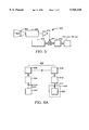
- FIG. 5 is a simplified schematic block diagram of a circuit interconnecting a photodetector with display light sources
- FIG. 6A is a block diagram illustrating the generation, transmission, reception, and processing of a video signal into a format suitable for a display system
- FIG. 6B is a block diagram illustrating the functions of video signal processing modules in connection with the use of intermediate frame memory with a display system.
- the invention relates generally to image display systems and more particularly to dual off-axis stereographic systems with multiple illumination sources for biocular viewing of single microdisplays.
- a compact biocular optical configuration provides a wide-angle image of a single display surface independently to each eye.
- FIG. 1 is a schematic view of an unfolded optical path off-axis biocular system 100, in accordance with the invention, incorporating a single transmissive display device 110 having a substantially planar display surface 108, as described in detail below.
- Display device 110 is positioned at the intersection of two independent beams 112 and 114 of nearly collimated light, defining respective substantially rectilinear beam axes 113 and 115.
- independent beams 112 and 114 are individually produced from a single or multiple light sources, as described in greater detail below.
- Independent beams 112 and 114 preferably each have collimated beam width (e.g. diameter 116) approximately equal to the width (e.g.
- Beam axes 113 and 115 are tilted relative to one another and to a display axis 117 perpendicular to display surface 108.
- Independent beams 112 and 114 propagate through display surface 108 along respective beam axes 113 and 115 to respective intermediate image planes 122 and 124.
- Single or multiple imaging elements 126 and 128 form intermediate images 132 and 134 of display surface 108 in space at intermediate image planes 122 and 124 respectively.
- imaging elements 126 and 128 incorporate toroidal optical correction to correct for off-axis geometric distortion.
- Intermediate image planes 122 and 124 are re-imaged by respective independent eyepiece lenses 136 and 138, configured to magnify intermediate image planes 122 and 124 respectively and to provide virtual images (not shown) for independent viewing by each eye 146, 148 of an observer. Because of the collimated nature of independent beams 112 and 114 at display surface 108 and the specific paths of the resultant beams through intermediate image planes 122 and 124, the optical energy of respective independent beams 112 and 114 does not fill the eyepiece apertures 142, 144. It has long been recognized by those having ordinary skill in the art, that optical energy must fill eyepiece apertures 142, 144 sufficiently in order to provide complete and uniform virtual images to the eyes 146, 148 of an observer.
- this condition is met in a traditional manner by inserting a field lens 152, 154 (see for example F. A. Jenkins and H. E. White: “Fundamentals of Optics,” McGraw-Hill New York, Toronto, London 3rd edition 1957, pp. 182-183) along beam axis 113, 115 at or near intermediate image plane 122, 124 to fill its respective eyepiece aperture 142, 144 for all possible fields of view.
- field lenses as described herein optionally include scattering screens and Fresnel lenses (see for example The Photonics Dictionary 1988, Laurin Publishing Co., Inc., Pittsfield, Mass.).
- field lens 152, 154 is given on-axis or off-axis toroidal power to correct residual image distortions and/or to accommodate the field curvature of the eyepiece design.
- Independent beam 112 propagating along beam axis 113, together with intermediate imaging plane 122, imaging element 126, eyepiece lens 136, eyepiece aperture 142, and any other optical elements lying along independent beam 112 are defined collectively as left optical channel 140.
- independent beam 114 propagating along beam axis 115, together with intermediate imaging plane 124, imaging element 128, eyepiece lens 138, eyepiece aperture 144, and any other optical elements lying along independent beam 114 are defined collectively as right optical channel 150.
- Off-axis biocular system 100 avoids the loss of light, bulk and expense of conventional beamsplitters, but illumination off-axis relative to of display axis 117 induces geometric distortion of the image of display surface 108, which must be accommodated or compensated. Accordingly the tilt angle between beam axes 113 and 115 is kept small enough to minimize geometric distortion but large enough so that optical components of the respective optical channels 140, 150 do not physically conflict with one another.
- left optical channel 140 uses single or multiple light-emitting diodes (LEDs) 162 as light sources, and their emissions are mixed and concentrated within a mixing light cone 166 to produce an approximate point light source 172.
- LEDs light-emitting diodes
- Light cones are familiar in the art for collecting and concentrating light, and can be fabricated readily by methods including machining, molding, casting, and electroforming.
- Imaging element 126 in left optical channel 140 projects intermediate image 132 of display surface 108 at intermediate image plane 122, where field lens 152 directs the optical energy in left optical channel 140 to fill left eyepiece aperture 142 uniformly.
- Left eyepiece lens 136 forms a virtual image (not shown) of intermediate image plane 122 for comfortable viewing.
- imaging element 126 incorporates toroidal correction to compensate for geometric distortion arising from the off-axis imaging of display surface 108.
- FIG. 1 also shows an aperture stop 182 inserted in at a plane of minimum convergence 186 of independent beam 112 between imaging element 126 and intermediate image plane 122.
- aperture stop 182 functions primarily to optimize contrast by blocking glare from stray and scattered light. If independent beam 112 is sufficiently collimated where it intersects display surface 108, then plane of minimum convergence 186 becomes an approximate Fourier transform plane (hereinafter the transform plane). Since independent beam 112 is incoherent, the transform plane is an approximate power Fourier transform plane and not an amplitude Fourier transform plane, which exists only in systems having coherent light.
- Aperture stop 182 is appropriately sized to transmit spatial frequencies corresponding with the desired image resolution (for example VGA), while blending finer detail due to the display device's sub-pixel structure by blocking higher-order spatial frequency harmonics (e.g. light displaced farther off-axis at the transform plane), thereby reducing "graininess" and improving image quality.
- right optical channel 150 uses single or multiple light-emitting diodes (LEDs) 164 as light sources, and their emissions are mixed and concentrated within a mixing light cone 168 to produce an approximate point light source 174.
- Light from point light source 174 is collected and collimated by a collimating lens 178 to produce substantially collimated independent beam 114.
- Independent beam 114 is obliquely incident on substantially planar display device 110.
- Imaging element 128 in right optical channel 150 projects intermediate image 134 of display surface 108 at intermediate image plane 124, where a field lens 154 directs the optical energy in right optical channel 150 to fill right eyepiece aperture 144 uniformly.
- Right eyepiece lens 138 forms a virtual image (not shown) of intermediate image plane 124 for comfortable viewing.
- imaging element 128 incorporates toroidal correction to compensate for geometric distortion arising from the off-axis imaging of display surface 108.
- FIG. 1 also shows an aperture stop 184 inserted at the plane of minimum convergence 188 of independent beam 114 propagating toward intermediate image plane 124.
- aperture stop 184 functions primarily to optimize contrast by blocking glare from stray and scattered light. If independent beam 114 is sufficiently collimated where it intersects display surface 108, then plane of minimum convergence 188 is also a transform plane.
- aperture stop 184 is appropriately sized to transmit spatial frequencies corresponding with the desired image resolution, while blending finer detail due to the display device's structure by blocking higher-order spatial frequency harmonics, thereby reducing "graininess" and thus improving image quality.
- Miniature display devices are available in both monochrome and color versions and in either transmissive or reflective configurations.
- Suppliers of transmissive microdisplays include Sony Semiconductor of San Jose, Calif.; and the Sharp, Canon, Seiko, Epson, and Kopin companies of Japan.
- Suppliers of reflective microdisplays include CRL of Dawley Road, Hayes, Middlesex, UK; CMD of Boulder, Colo.; Displaytech, Inc. of Longmont, Colo.; and Varitronix Limited of Hong Kong.
- a reflective micromirror display device is produced by Texas Instruments of Dallas, Tex.
- Color display devices are generally supplied with microdot or microstrip color filters, requiring at least three pixels (red, green, and blue) to create a single color display element. As will be apparent to one skilled in the art, this compromises resolution and sacrifices optical efficiency. For display devices that are capable of sub-frame rate switching speeds, another option is to apply to each pixel sequential color techniques such as those used in early television with color wheels or, more recently, electro-optic switchable filters.
- light-emitting diodes 162 of left optical channel 140 comprise a group of red, green and blue color LEDs, for example 162r, 162g,162b. LEDs 162r-g-b illuminate the input aperture to mixing light cone 166.
- light-emitting diodes 164 of right optical channel 150 comprise a group of red, green and blue color LEDs, for example 164r, 164g, 164b, which illuminate the input aperture to mixing light cone 168.
- LEDs 162r-g-b, 164r-g-b are sequentially switched for color in any manner that is compatible with an appropriately fast display device 110.
- red LEDs 162r, 164r are switched on and all other LEDs are switched off synchronously, while a red frame video signal is applied to display device 110.
- electro-optic detectors 192, 194 are positioned to sample the optical outputs within appropriate color bands in respective left and right optical channels 140, 150 and appropriately adjust the drive currents with closed-loop electronic feedback.
- the outputs from LEDs 162, 164 are captured by diffractive collectors 170, 171 and are mixed and homogenized in mixing light cones 166, 168, as described in detail below.
- Diffractive collectors 170, 171 are configured to diffract and superimpose the respective color components from LEDs 162r-g-b within mixing light cones 166, 168.
- true stereographic viewing is provided by alternate sequencing of the right and left groups of LEDs 162, 164, synchronously with time-domain multiplexing of alternate right and left video signals.
- the present embodiment provides for alternate sequencing of separate right and left groups of LEDs 162, 164 for separate optical channels 140, 150 respectively.
- Off-axis biocular system 100 provides unique true stereographic viewing capability with a single display device 110, because left and right optical channels 140 and 150 remain optically independent of one another from illumination sources 162, 164 to the observer's eyes 146, 148, except for sharing common display device 110.
- stereographic video sequencing is performed concurrently with the above-described sequential color switching at a sequencing rate and in a combination that minimizes visual flicker.
- eyepiece lenses 136, 138 comprise reflective and/or refractive lens elements.
- eyepiece lenses 136, 138 are color-corrected (achromatic) to enhance color and image fidelity.
- Eyepiece lenses 136, 138 have eye relief ranging from approximately 0.5 inch to 0.7 inch and angular aperture ranging from approximately 20 degrees to 40 degrees full angle.
- eyepiece lenses 136, 138 are further refined by using surfaces with higher order curvatures (aspheric surfaces) to minimize aberrations.
- Such lenses tend to be quite thick and heavy, generally require multiple elements for achromatic performance, and are difficult and expensive to fabricate.
- Conventional plastic injection-molded lenses can utilize the opposite color dispersions of refractive and diffractive surfaces to create simpler, lighter, and less expensive achromats, but the appropriate lenses are typically delicate and tend to scatter light.
- FIGS. 2A-2G are schematic views of thin color-corrected lens elements, illustratively for use in biocular display system 100, in some embodiments of the invention.
- FIG. 2A shows a conventional singlet refractive lens 210, having significant color distortion. Illustratively red, green, and blue color images of point object 208 are focused in sequence at points labeled R, G, and B respectively (exaggerated for clarity).
- FIG. 2A shows a conventional singlet refractive lens 210, having significant color distortion. Illustratively red, green, and blue color images of point object 208 are focused in sequence at points labeled R, G, and B respectively (exaggerated for clarity).
- FIG. 2B shows a continuously-profiled Fresnelled refractive surface 220, having reduced weight and thickness relative to conventional refractive lens 210, but also having color distortion such that the red, green, and blue color images of point object 218 are focused at points labeled R, G, and B respectively, in the same sequence as for conventional refractive lens 210.
- FIG. 2C shows a diffractive surface 230 used as a lens. Diffractive surface 230 is compact and light-weight, and also has color distortion, but in a reverse sequence relative to that for lens 210 and Fresnelled refractive surface 220, as illustrated by red, green, and blue color image points of point object 228 labeled R, G, and B respectively.
- two conventional refractive lenses 210 and 212 having different curvatures and materials can be combined for color correction, as illustrated by the superposition of color image points of point object 238 labeled R, G, B in FIG. 2D.
- FIG. 2E shows diffractive-refractive lens 240 combining diffractive surface 230 with Fresnelled refractive surface 220.
- diffractive-refractive lens 240 applies the offsetting color distortion sequences of diffractive surface 230 and Fresnelled refractive surface 220 to achieve color correction, as illustrated by the superposition of color image points of point object 248 labeled R, G, B in FIG. 2E.
- multiple thin optical elements are used for each eyepiece with any combination of smooth, refractive, and diffractive surfaces for improved control of optical aberrations.
- the outer surface (eye side) is preferably smooth for improved cleanability. The more delicate diffractive surfaces are thereby protected as intermediate surfaces.
- Fresnelled refractive surfaces 220 and/or diffractive surfaces 230 are applied to complex substrate curvatures 216 for greater design versatility, as illustrated by a complex refractive-diffractive lens 250 in FIG. 2F.
- Illustratively complex refractive-diffractive lens 250 corrects chromatic distortion (superposition of color image points labeled R, G, B) for both an on-axis point object 252 and an off-axis point object 254.
- FIG. 2G is a schematic view of a complex refractive-diffractive eyepiece lens 260, incorporating chromatic and geometric correction.
- Eyepiece lens 260 is placed less than one focal length away from an object 262, and creates a virtual image 264 of object 262 at a distance greater than one focal length from eyepiece lens 260, as viewed through eyepiece lens 260 by an observer 266.
- Virtual image 264 retains chromatic and geometric fidelity.
- Object 262 can be a physical object or a projected intermediate real image.
- color correction of an eyepiece lens can require a superposition of multiple refractive and diffractive surfaces applied to complex substrate curvatures. This in turn increases manufacturing costs.
- a simpler and less expensive system approach is employed, in which selected optical elements in the system are color overcorrected, whereas other optical elements are uncorrected or minimally corrected for color. Using such a system approach, overall system performance is made achromatic by balancing offsetting color distortions of individual optical elements.
- a diffractive lens surface 230 is applied to imaging elements 126 and 128 (see FIG. 1) either alone or in combination with other optical structures (e.g. toroidal correction). This results in color overcorrection, i.e. red, green, and blue color image points labeled R, G, B of point object 228 occur in the sequence shown in FIG. 2C. If imaging elements 126, 128 are appropriately color overcorrected, then field lenses 152, 154 and eyepiece lenses 136, 138 need not be individually achromatic for overall off-axis biocular system 100 to be achromatic. As needed, field lenses 152, 154 and/or eyepiece lenses 136, 138 are minimally color corrected.
- chromatic correction at planes of minimum convergence 186, 188, which are images of point sources 172, 174 respectively.
- To filter the fine sub-image structure requires a small diameter aperture stop 182, 184 at planes of minimum convergence 186, 188.
- Chromatic distortion separates the planes of minimum convergence for different colors, e.g. R, G, B, and thereby causes a loss of image resolution accompanying the sub-image structure filtering.
- Chromatic correction keeps the planes of minimum convergence 186, 188 in register for all colors. Therefore minimal sacrifice of image resolution accompanies sub-image structure filtering.
- the optical elements between point sources 172, 174 and their images in planes of minimum convergence 186, 188 are individually non-corrected but are overall corrected chromatically.
- collimating lenses 176, 178 are color undercorrected and imaging elements 126, 128 are color overcorrected so that the net result is chromatic correction at planes of minimum convergence 186, 188. In some embodiments this is combined with color undercorrection of eyepiece lens 136, 138. Since display surface 108 lies in a collimated beam, collimating lens 176, 178 has no effect on image color fidelity at eyepiece lens 136, 138. Therefore the designer is free to use color overcorrection of imaging elements 126, 128 to compensate for color undercorrection of eyepiece lens 136, 138, as described above.
- Plastic lenses are commonly injection molded from a variety of optically transparent materials, including acrylic, polycarbonate, styrene, and nylon.
- optical design and fabrication methods described in the above embodiments for particular optical elements are illustrative and are applicable to other optical elements in the system, as required for a particular configuration. Detailed selection of locations and properties of optical elements, e.g. focal lengths and aperture diameters, is performed in accordance with techniques familiar in the art.
- FIGS. 3A-3D are cross-sectional views of a folded optical path, reflective display biocular system 300, in accordance with the invention.
- This embodiment allows a more compact folded optical configuration, for example for use in a head-mounted display, than does the unfolded biocular off-axis system 100 shown in FIG. 1.
- reflective display biocular system 300 performs substantially the same functions as unfolded biocular off-axis system 100, and each system contains elements that are essentially functional counterparts of elements of the other system.
- Some elements that are transmissive in biocular off-axis system 100 are reflective in reflective display biocular system 300. Elements that are substantially similar in the various figures are designated by similar reference numbers.
- FIG. 3A is a top cutaway projection showing a left eyepiece assembly 280 and a molded optical assembly 290.
- Left eyepiece assembly comprises a field lens 352 located at or proximate to an intermediate image plane 122, a deflecting mirror 282, and an eyepiece lens 336.
- eyepiece lens 336 consists of a single refractive or refractive-diffractive optical element.
- eyepiece lens 336 comprises multiple refractive, Fresnelled refractive, and/or refractive-diffractive surfaces applied to planar or curved substrates, as described above in connection with FIGS. 2A-2G.
- Molded optical assembly 290 and left eyepiece assembly 280 are separated by half an interocular distance 284 that is adjustable by an interocular adjustment mechanism (not shown), coupled to molded optical assembly 290 and left eyepiece assembly 280.
- field lens 352 is separated from deflecting mirror 282 by a focus adjustment distance 286, adjustable by a focus adjustment mechanism (not shown) coupled to field lens 352 and deflecting mirror 282.
- FIG. 3B is a cross-sectional view showing molded optical assembly 290 as viewed across section 3B--3B of FIG. 3A.
- FIG. 3C is a cross-sectional view of molded optical assembly 290 showing an illumination path as viewed across section 3C--3C of FIG. 3A
- FIG. 3D is a cross-sectional view of molded optical assembly 290 showing an imaging path as viewed across section 3D--3D of FIG. 3A.
- Molded optical assembly 290 mounts on a substrate 292 by means of spacers 294.
- substrate 292 is a printed circuit board.
- Substrate 292 also supports light sources, preferably LEDs 162, 164, and a reflective display device 310 in a nominally planar relationship.
- LEDs 162 comprise red, green, and blue color LEDs 162r-g-b and 164r-g-b respectively (see FIG. 1).
- Molded optical assembly 290 includes total internally reflective (TIR) surfaces 372 and 374, collimating lens 376, imaging elements 326 and 328, and TIR stop 382. Molded optical assembly 290 further includes mixing light cones 166, 168, equipped with diffractive collectors 170, 171 respectively adjacent LEDs 162, 164.
- TIR total internally reflective
- molded optical assembly 290 is fabricated in whole or in part as a monolithic, unitary structure with self-contained optical components, as described in Hebert U.S. Pat. No. 5,596,454, issued Jan. 21, 1997. Integrally molded mechanical features allow for precise registration of the optical elements of molded optical assembly 290 relative to one another and relative to substrate 292 and thereby relative to LEDs 162, 164 and reflective display device 310 mounted on substrate 292. In other embodiments molded optical assembly 290 is fabricated as a frame onto which individual optical elements are assembled.
- a video signal is applied to reflective display device 310, thereby producing a reflective video image on reflective display surface 308.
- the video signal comes from a remote video camera (not shown).
- a computer graphic generator synthesizes the video signal.
- the video signal is supplied from data previously stored on disk, tape, or other storage medium. Acquisition and processing of the video signal is described below in greater detail.
- Reflective display surface 308 is illuminated by light beams defining independent left optical channel 340 and right optical channel 350 respectively.
- Arrows labeled 340 in FIGS. 3A-3D represent the beam propagation path of left optical channel 340.
- the beam propagation path of right optical channel 350 is symmetric with that of left optical channel 340, but is not labeled for clarity.
- Each optical element of right optical channel 350 is a symmetric counterpart and performs a function identical to that of a corresponding optical element of left optical channel 340.
- Beam propagation paths are laid out so that left optical channel 340 and right optical channel 350 intersect only at reflective display surface 308, ensuring that optical elements of respective left and right optical channels 340 and 350 do not interfere physically with one another.
- image distortion is produced in left and right optical channels 340, 350 respectively, because of off-axis illumination of reflective display surface 308.
- illumination for left optical channel 340 is generated by LEDs 162.
- LEDs 162 comprise color LEDs 162r-g-b, whereas in other embodiments the illumination is monochrome.
- the outputs from LEDs 162 are captured by diffractive collector 170 and are mixed and homogenized in mixing light cone 166.
- Diffractive collector 170 is configured to deflect and superimpose the respective color components from LEDs 162r-g-b within mixing light cone 166. Illustratively each differing color component from LED 162r, 162g,162b respectively impinges on diffractive collector 170 at a differing angle of incidence. Diffractive collector 170 is configured so that the respective color components are diffracted at differing angles, such that the diffracted color components are all substantially superimposed and propagate together within mixing light cone 166, as if these color components were all emitted from a spatially common light source.
- This application of diffractive collector 170 is essentially the inverse of typical diffractive surfaces, wherein a single light beam comprising differing color components is diffracted into a plurality of separate light beams each having differing angles for differing color components.
- Beam 340 emerges from mixing light cone 166 substantially as a point source of light, which is deflected by TIR reflective aperture 372. After being collected and reflected by a TIR folding surface 374, beam 340 passes through collimating lens 376, producing a substantially parallel beam 340 that reflects obliquely from reflective display surface 308 (see diagonal arrow 340 in FIG. 3A). At reflective display surface 308, beam 340 is spatially modulated by a video image. In some embodiments color LEDs 162r-g-b are sequenced synchronously with a color video signal to reflective display device 310, thereby producing a sequentially color modulated reflected beam, as described above in connection with FIG. 1.
- imaging element 326 is a transmissive element that combines refractive, Fresnelled refractive, and/or diffractive properties.
- Imaging element 328 is a TIR reflective element disposed to fold beam 340 toward TIR stop 382, which then deflects beam 340 toward intermediate image plane 122 (see FIGS. 3A-3B).
- imaging element 328 incorporates curvature, which combined with transmissive imaging element 326, focuses beam 340 through a plane of minimum convergence at TIR stop 382 and then to form an intermediate image of reflective display surface 308 at intermediate image plane 122.
- imaging element 326 and/or 328 incorporates toroidal correction to compensate for image distortion arising from off-axis imaging of display surface 308.
- TIR stop 382 combines the function of folding beam 340 toward left eyepiece assembly 280 with an aperture stop function, similar to aperture stops 182, 184 described above in connection with FIG. 1.
- TIR stop 382 comprises a small TIR element that reflects the central portion of beam 340 at substantially a right angle toward left eyepiece assembly 280, while letting undesired diffracted and scattered light pass harmlessly around it.
- Molded optical assembly 290 advantageously uses TIR surfaces to reflect beam 340 efficiently without the need for expensive optical coatings. This design approach facilitates unitary fabrication of molded optical assembly 290.
- intermediate image 132 of the present embodiment are substantially identical with those of intermediate image 132 described above in connection with FIG. 1.
- field lens 352 is placed at intermediate image plane 122, in order to fill the aperture of eyepiece lens 336 with optical energy.
- a deflecting mirror 282 to fold beam 340 is inserted between intermediate image plane 122 and eyepiece lens 336.
- optical element configurations as described above, is applicable to reflective display biocular system 300. These configurations include transmissive and reflective, off-axis, toroidal, refractive, diffractive, and Fresnelled refractive elements.
- a system design approach to color correction as described above in connection with FIGS. 2A-2G, is applied to reflective display biocular system 300. With such a system design approach, the overall system performance is made achromatic by balancing the offsetting color distortions of individual optical elements.
- a diffractive lens surface 230 is applied to imaging element 326 (see FIG. 3D) either alone or in combination with other optical structures (e.g. toroidal correction).
- imaging element 326 is appropriately color overcorrected, then field lens 352 and eyepiece lens 336 need not be individually achromatic for overall reflective display biocular system 300 to be achromatic. As needed, field lens 352 and/or eyepiece lens 336 is minimally color corrected.
- chromatic correction at the plane of minimum convergence substantially coincident with TIR stop 382, at which an image of TIR reflective aperture 372 is formed.
- Chromatic correction keeps the plane of minimum convergence in register for all colors, minimizing loss of image resolution with sub-image structure filtering.
- the optical elements between TIR reflective aperture 372 and its image at TIR stop 382, namely collimating lens 376 and imaging elements 326, 328, are individually non-corrected but are collectively corrected chromatically.
- collimating lens 376 is color undercorrected, but imaging element 326 is color overcorrected, so that the net result is chromatic correction at TIR stop 382. In some embodiments, this is combined with color undercorrection of eyepiece lens 336. Since reflective display surface 308 lies in a collimated region of beam 340, collimating lens 376 has no effect on image color fidelity at eyepiece lens 336. Therefore a system designer is free to use color overcorrection of imaging element 326 to offset color undercorrection of eyepiece lens 336, as described above.
- true stereographic viewing is provided by alternate sequencing of the right and left groups of LEDs 162, 164, synchronously with time-domain multiplexing of alternating right and left video signals, as described above in connection with FIG. 1.
- Reflective display biocular system 300 provides unique true stereographic viewing capability with a single reflective display device 310, because left and right optical channels 340 and 350 remain optically independent of one another, except for sharing common reflective display device 310.
- stereographic video sequencing is performed concurrently with the above-described sequential color switching at a sequencing rate and in a combination that minimizes visual flicker.
- FIG. 4A is a front elevational view of a biocular display viewing system 400 incorporating a head-mounted display (HMD) housing 410 containing, for example, an off-axis biocular system 100 or a reflective display biocular system 300 and incorporating interchangeable corrective peripheral vision lens elements 422, 424, in accordance with the invention.
- HMD head-mounted display
- FIG. 4B is a side elevational view of the biocular display viewing system of FIG. 4A.
- an appropriate HMD device For users requiring corrected vision, an appropriate HMD device must either provide eye relief space to accommodate eyeglasses, or provide eyepiece-focusing adjustments. Accommodating eyeglasses compromises the ergonomic mechanical design of the device in that the eye relief must be extended beyond the surface of the eyeglasses. Thus, the device becomes bulkier, heavier and generally less comfortable.
- biocular display viewing system 400 provides eyepiece-focusing adjustments (not shown).
- true peripheral vision correction is required for a typical user environment.
- interchangeable corrective peripheral vision lens elements 422, 424 are integrated into a HMD housing, as illustrated in FIGS. 4A-4B.
- a few general optical prescriptions potentially satisfy a range of peripheral vision requirements; generally in the range of -0.5 to +1.5 diopter. This is especially true for a limited-distance peripheral vision requirement, as in a computer workplace environment.
- interchangeable corrective peripheral vision lenses 422, 424 are made of injection-molded plastic with integrally molded snap features (not shown), which permit easy, interchangeable installation onto a compatibly designed HMD housing 410.
- commercially available eyeglass lens blanks may be milled and shaped to fit the HMD.
- corrective peripheral vision lens elements 422, 424 While many configurations are possible for corrective peripheral vision lens elements 422, 424, a wrap-around configuration as illustrated in FIG. 4A is generally preferred for optimum peripheral vision, wherein corrective peripheral vision lens elements 422, 424 include cutout segments to surround respective left and right eyepiece lenses 336, 337.
- FIG. 4C is a top view illustrating schematically how a biocular display viewing system 430 similar to that described in connection with FIGS. 3A-3D fits into a head-mounted display (HMD) housing.
- HMD housing 432 (shown in shaded outline in FIG. 4C) with earpieces 434, 436 and corrective peripheral vision lens elements 422, 424 contains a reflective display biocular system 300, incorporating molded optical assembly 290, as viewed in FIG. 3A.
- Molded optical assembly 290 incorporates a substrate 292 (preferably a printed circuit board) to which a reflective display device and LED light sources (hidden beneath molded optical assembly 290 are attached.
- Left and right imaging beams emerge from molded optical assembly 290 and are directed to left and right eyes respectively by left field lens 352, left deflecting mirror 282, and left eyepiece lens 336, and by right field lens 353, right deflecting mirror 283, and right eyepiece lens 337.
- FIG. 4D is an elevational view illustrating a photodetector 452 mounted with an input lens 454 on HMD housing 410.
- Photodetector 452 is disposed to have an ambient field of view 456 through input lens 454 that approximates the peripheral field of view 458 of observer 460.
- peripheral field of view 458 of observer 460 is taken through corrective peripheral vision lens elements 424 and 422.
- FIG. 5 is a simplified schematic block diagram of a circuit 500 interconnecting photodetector 452 with display light sources (for example LEDs 162r-g-b, 164r-g-b, see FIG. 1).
- Photodetector 452 is positioned behind input lens 454 and has an output terminal connected to an input terminal of an amplifier 472.
- Amplifier 472 in turn has an output terminal connected to a reference input terminal of a summing junction 474.
- a signal input terminal of summing junction 474 is connected to the output terminal of a nominal contrast and intensity control module 476.
- the output terminal of summing junction 474 is connected to the input terminal of a light source driver 478, which has an output terminal connected to the light source.
- light source driver 478 represents a plurality of light source drivers, each driving an individual light source, for example LED 162r.
- circuit 500 represents a plurality of individual circuits comprising individual photodetectors, amplifiers, and light source drivers.
- circuit 500 includes input terminals (not shown) interconnected with light source sequencing apparatus.
- all of the elements of circuit 500 are contained in or on HMD housing 410.
- having any and all of the elements of circuit 500, including photodector 452 and input lens 454, located separately from HMD housing 410 are also within the scope of the invention.
- illustratively input lens 454 collects ambient light over ambient field of view 456 and concentrates the collected ambient light on the sensing element of photodetector 452, which generates an output signal proportional to the intensity of the collected ambient light.
- the output signal from photodetector 452 is amplified by amplifier 472, which generates a reference signal and applies it to the reference terminal of summing junction 474.
- Summing junction 474 combines the reference signal with control signals provided by nominal contrast and intensity control module 476, and generates adjusted contrast and intensity control signals, which are applied to the input terminals of light source drivers 478.
- the adjusted contrast and intensity control signals automatically adjust the intensity of light sources, e.g. LEDs 162, 164, for a near-constant ratio to the ambient light intensity, without the need for continual manual intensity adjustment in a continually changing ambient light environment.
- FIG. 6A is a block diagram illustrating the generation, transmission, reception, and processing of a video signal into a format suitable for a display system, in an embodiment of the invention.
- a source device 602 generates video signals in a conventional RG2-VGA format in the analog domain. These signals are transmitted either by cable (not shown) or by an appropriate wireless data link 606 comprising a transmitter 608 and a receiving module 610 connected with a processing module 612.
- Processing module 612 is physically located at or adjacent to a display device 620 as described above in connection with FIGS. 1 and 3A-3D, or located independently.
- a preprocessing module 604 (shown in dashed outline) is located at or adjacent to source device 602 and is interconnected between source device 602 and transmitter 608.
- An independently located processing module 612 is typically connected to display device 620 by a short cable 614.
- a processing module 612 can be incorporated into an optional head-mounted display housing 618 (shown in dashed outline).
- processing module 612 is attached conveniently for example to a user's clothing (not shown) and connected into head-mounted display housing 618 by a short, minimally encumbering cable 614.
- Processing modules 604, 612 convert video signals into a format required by display device 620.
- visual quality of a display requires a frame rate that minimizes the eye's perception of flicker. But the flicker frame rate requirement is about four times faster than that required to create a sense of continuous motion of an object within an image.
- many miniature display devices appropriate to the invention are not directly scan-compatible with the standard RGB interface and require an intermediate memory (frame grabber) for scan format conversion. Where intermediate memory is a requirement, the display device refreshes from the intermediate memory at a frame rate to minimize flicker, but the intermediate memory is updated only at a slower frame rate consistent with image motion requirements.
- intermediate memory frame grabber
- FIG. 6B is a block diagram illustrating the functions of processing modules 604, 612 in connection with the use of intermediate frame memory with a display system, in an embodiment of the invention.
- Inputs from a conventional RGB video source (not shown) are received by a serial multiplexer 640 and a shift register 644 incorporated into processing module 604.
- the vertical sync pulse from the video source causes shift register 644 to control multiplexer 640 to generate large sequential color frames of video data.
- These are combined with vertical and horizontal sync pulses in a combiner module 642, optionally, audio signals are embedded into the horizontal sync pulses of the video waveform in combiner module 642.
- a combined video signal from combiner module 642 is transmitted over wireless date link 606 from transmitter 608 to receiving module 610 and is applied to processor module 612.
- processor module 612 the video signal is optionally amplified in conventional automatic gain control module 630 and is then separated into its respective video, sync, and audio components by sync separator 632.
- the various signal components are appropriately applied to the intermediate memory (not shown), which interfaces with the input electronics of display device 620.
- true stereographic viewing is achieved using a single display device with appropriate inexpensive optics and without a beamsplitter.
- Low-cost complex plastic optics allow biocular viewing of a single electro-optic display device, such as for use in a head-mounted display (HMD).
- a dual off-axis configuration provides two independent optical channels, intersecting only at the image surface of the display device.
- Each optical channel contains its own illumination source, eyepiece lens, and imaging optics.
- nearly collimated illumination optics and intermediate field lenses are used to fill wide-aperture eyepieces without the need for a beamsplitter.
- true stereographic performance is achieved by sequential activation of the light sources in the two channels in synchronism with sequential video signals for the respective channels.
- Offsetting color overcorrection and undercorrection methods are applied to minimize optical element complexity. Additional features include lightweight achromatic eyepiece construction and interchangeable lenslets for peripheral vision correction, and automatic contrast and intensity compensation.
- a video interface converts conventionally formatted video signals to serially multiplexed color data, which fills an intermediate frame refresh memory. Versions of the video interface include wireless transmission, eliminated cumbersome cabling.
- embodiments of the invention provide the depth perception, high resolution, high color fidelity, peripheral vision correction, and convenience of use in a head-mounted configuration to satisfy the demanding requirements of medical and surgical remote viewing.
- a compact, high resolution, high contrast, truly stereographic system for microdisplay viewing, that is suitable for head-mounted display use without requiring undue complexity or expense.
- the system provides color correction for good color fidelity, and incorporates ergonomic features for comfort and efficiency, including wide-angle display viewing with long eye relief, and peripheral vision accommodation.
- Wireless versions eliminate the need for cumbersome cabling.
- high resolution, high color fidelity, truly stereographic viewing in a head-mounted display, including peripheral vision accommodation and wireless transmission provides the depth perception and convenience required for medical and surgical remote viewing.
Abstract
Description
Claims (80)
Priority Applications (8)
| Application Number | Priority Date | Filing Date | Title |
|---|---|---|---|
| US09/056,934 US5926318A (en) | 1998-04-06 | 1998-04-06 | Biocular viewing system with intermediate image planes for an electronic display device |
| US09/241,828 US6008939A (en) | 1998-04-06 | 1999-02-01 | Method of color correction in a color video display system |
| AU22553/99A AU2255399A (en) | 1998-04-06 | 1999-03-31 | Biocular viewing system with intermediate image planes for an electronic display device |
| CA002267876A CA2267876C (en) | 1998-04-06 | 1999-03-31 | Biocular viewing system with intermediate image planes for an electronic display device |
| JP11097463A JP2000035551A (en) | 1998-04-06 | 1999-04-05 | System for visual confirmation with both eyes for electronic display device having intermediate image plane |
| EP99302669A EP0949826A3 (en) | 1998-04-06 | 1999-04-06 | Biocular viewing system with intermediate image planes for an electronic display device |
| US09/362,927 US6040946A (en) | 1998-04-06 | 1999-07-27 | Color superposition and mixing of light beams for a video display system |
| US09/373,807 US6219186B1 (en) | 1998-04-06 | 1999-08-13 | Compact biocular viewing system for an electronic display |
Applications Claiming Priority (1)
| Application Number | Priority Date | Filing Date | Title |
|---|---|---|---|
| US09/056,934 US5926318A (en) | 1998-04-06 | 1998-04-06 | Biocular viewing system with intermediate image planes for an electronic display device |
Related Child Applications (1)
| Application Number | Title | Priority Date | Filing Date |
|---|---|---|---|
| US09/241,828 Division US6008939A (en) | 1998-04-06 | 1999-02-01 | Method of color correction in a color video display system |
Publications (1)
| Publication Number | Publication Date |
|---|---|
| US5926318A true US5926318A (en) | 1999-07-20 |
Family
ID=22007457
Family Applications (3)
| Application Number | Title | Priority Date | Filing Date |
|---|---|---|---|
| US09/056,934 Expired - Lifetime US5926318A (en) | 1998-04-06 | 1998-04-06 | Biocular viewing system with intermediate image planes for an electronic display device |
| US09/241,828 Expired - Lifetime US6008939A (en) | 1998-04-06 | 1999-02-01 | Method of color correction in a color video display system |
| US09/362,927 Expired - Lifetime US6040946A (en) | 1998-04-06 | 1999-07-27 | Color superposition and mixing of light beams for a video display system |
Family Applications After (2)
| Application Number | Title | Priority Date | Filing Date |
|---|---|---|---|
| US09/241,828 Expired - Lifetime US6008939A (en) | 1998-04-06 | 1999-02-01 | Method of color correction in a color video display system |
| US09/362,927 Expired - Lifetime US6040946A (en) | 1998-04-06 | 1999-07-27 | Color superposition and mixing of light beams for a video display system |
Country Status (5)
| Country | Link |
|---|---|
| US (3) | US5926318A (en) |
| EP (1) | EP0949826A3 (en) |
| JP (1) | JP2000035551A (en) |
| AU (1) | AU2255399A (en) |
| CA (1) | CA2267876C (en) |
Cited By (61)
| Publication number | Priority date | Publication date | Assignee | Title |
|---|---|---|---|---|
| US6008778A (en) * | 1997-03-04 | 1999-12-28 | Olympus Optical Co., Ltd. | Visual display apparatus |
| US6115182A (en) * | 1998-04-08 | 2000-09-05 | Asahi Kogaku Kogyo Kabushiki Kaisha | Real-time optical finder system |
| US6219186B1 (en) * | 1998-04-06 | 2001-04-17 | Optimize Incorporated | Compact biocular viewing system for an electronic display |
| US6271808B1 (en) * | 1998-06-05 | 2001-08-07 | Silicon Light Machines | Stereo head mounted display using a single display device |
| US6404557B2 (en) | 1999-09-10 | 2002-06-11 | Inviso, Inc. | Display illumination system |
| US20030025709A1 (en) * | 2001-07-31 | 2003-02-06 | Lg Electronics Inc. | Circuit and method for driving self light-emitting display device |
| US6546208B1 (en) | 1999-11-22 | 2003-04-08 | Sl3D, Inc. | Stereoscopic telescope with camera |
| US20030068057A1 (en) * | 2001-10-06 | 2003-04-10 | Miller Eric C. | Information system using eyewear for communication |
| US20040004584A1 (en) * | 2002-03-20 | 2004-01-08 | Raymond Hebert | Head-mounted viewing system for single electronic displays using biocular lens with binocular folding mirrors |
| US6707591B2 (en) | 2001-04-10 | 2004-03-16 | Silicon Light Machines | Angled illumination for a single order light modulator based projection system |
| US20040057107A1 (en) * | 2001-11-09 | 2004-03-25 | Xradia, Inc. | Reflective lithography mask inspection tool based on achromatic fresnel optics |
| US6712480B1 (en) | 2002-09-27 | 2004-03-30 | Silicon Light Machines | Controlled curvature of stressed micro-structures |
| US6714337B1 (en) | 2002-06-28 | 2004-03-30 | Silicon Light Machines | Method and device for modulating a light beam and having an improved gamma response |
| US6728023B1 (en) | 2002-05-28 | 2004-04-27 | Silicon Light Machines | Optical device arrays with optimized image resolution |
| US20040085641A1 (en) * | 2001-11-09 | 2004-05-06 | Xradia, Inc. | Achromatic fresnel optics based lithography for short wavelength electromagnetic radiations |
| US6747781B2 (en) | 2001-06-25 | 2004-06-08 | Silicon Light Machines, Inc. | Method, apparatus, and diffuser for reducing laser speckle |
| US6764875B2 (en) | 1998-07-29 | 2004-07-20 | Silicon Light Machines | Method of and apparatus for sealing an hermetic lid to a semiconductor die |
| US6767751B2 (en) | 2002-05-28 | 2004-07-27 | Silicon Light Machines, Inc. | Integrated driver process flow |
| US20040150888A1 (en) * | 2002-11-19 | 2004-08-05 | Push Technologies, Inc. | Multiple imaging arrangements for head mounted displays |
| US6782205B2 (en) | 2001-06-25 | 2004-08-24 | Silicon Light Machines | Method and apparatus for dynamic equalization in wavelength division multiplexing |
| US6795241B1 (en) | 1998-12-10 | 2004-09-21 | Zebra Imaging, Inc. | Dynamic scalable full-parallax three-dimensional electronic display |
| US6800238B1 (en) | 2002-01-15 | 2004-10-05 | Silicon Light Machines, Inc. | Method for domain patterning in low coercive field ferroelectrics |
| US6801354B1 (en) | 2002-08-20 | 2004-10-05 | Silicon Light Machines, Inc. | 2-D diffraction grating for substantially eliminating polarization dependent losses |
| US6806997B1 (en) | 2003-02-28 | 2004-10-19 | Silicon Light Machines, Inc. | Patterned diffractive light modulator ribbon for PDL reduction |
| US6822797B1 (en) | 2002-05-31 | 2004-11-23 | Silicon Light Machines, Inc. | Light modulator structure for producing high-contrast operation using zero-order light |
| US6829092B2 (en) | 2001-08-15 | 2004-12-07 | Silicon Light Machines, Inc. | Blazed grating light valve |
| US6829258B1 (en) | 2002-06-26 | 2004-12-07 | Silicon Light Machines, Inc. | Rapidly tunable external cavity laser |
| US6829077B1 (en) | 2003-02-28 | 2004-12-07 | Silicon Light Machines, Inc. | Diffractive light modulator with dynamically rotatable diffraction plane |
| US20050047473A1 (en) * | 2003-08-29 | 2005-03-03 | Gruhlke Russell W. | Method of enhancing wavelength tuning performance in an external cavity laser |
| US20050185277A1 (en) * | 2000-01-31 | 2005-08-25 | 3M Innovative Properties Company | Illumination system for reflective displays |
| US20060055786A1 (en) * | 2004-03-09 | 2006-03-16 | Viosport | Portable camera and wiring harness |
| US20070167840A1 (en) * | 2005-12-29 | 2007-07-19 | Amit Pascal | Device and method for in-vivo illumination |
| US20070273983A1 (en) * | 2006-05-26 | 2007-11-29 | Hebert Raymond T | Devices, methods, and systems for image viewing |
| US7375894B2 (en) | 2006-03-07 | 2008-05-20 | Gentex Corporation | Common lens helmet mounted display |
| US20090234225A1 (en) * | 2008-01-10 | 2009-09-17 | The Ohio State University Research Foundation | Fluorescence detection system |
| US20100113940A1 (en) * | 2008-01-10 | 2010-05-06 | The Ohio State University Research Foundation | Wound goggles |
| US20110234861A1 (en) * | 2010-03-23 | 2011-09-29 | Fujifilm Corporation | Imaging device |
| US8526575B1 (en) * | 2009-08-12 | 2013-09-03 | Xradia, Inc. | Compound X-ray lens having multiple aligned zone plates |
| US8576143B1 (en) | 2010-12-20 | 2013-11-05 | Google Inc. | Head mounted display with deformation sensors |
| US8666212B1 (en) | 2011-04-28 | 2014-03-04 | Google Inc. | Head mounted display using a fused fiber bundle |
| US8705177B1 (en) | 2011-12-05 | 2014-04-22 | Google Inc. | Integrated near-to-eye display module |
| US8749886B2 (en) | 2012-03-21 | 2014-06-10 | Google Inc. | Wide-angle wide band polarizing beam splitter |
| US8760765B2 (en) | 2012-03-19 | 2014-06-24 | Google Inc. | Optical beam tilt for offset head mounted display |
| US8848289B2 (en) | 2012-03-15 | 2014-09-30 | Google Inc. | Near-to-eye display with diffractive lens |
| US8867139B2 (en) | 2012-11-30 | 2014-10-21 | Google Inc. | Dual axis internal optical beam tilt for eyepiece of an HMD |
| US8867131B1 (en) | 2012-03-06 | 2014-10-21 | Google Inc. | Hybrid polarizing beam splitter |
| US8873148B1 (en) | 2011-12-12 | 2014-10-28 | Google Inc. | Eyepiece having total internal reflection based light folding |
| US20150015461A1 (en) * | 2012-03-22 | 2015-01-15 | Sony Corporation | Head-mounted display |
| US9116337B1 (en) | 2012-03-21 | 2015-08-25 | Google Inc. | Increasing effective eyebox size of an HMD |
| US9194995B2 (en) | 2011-12-07 | 2015-11-24 | Google Inc. | Compact illumination module for head mounted display |
| US9285591B1 (en) | 2014-08-29 | 2016-03-15 | Google Inc. | Compact architecture for near-to-eye display system |
| US9329388B1 (en) | 2011-04-28 | 2016-05-03 | Google Inc. | Heads-up display for a large transparent substrate |
| US20160282183A1 (en) * | 2015-03-23 | 2016-09-29 | Seiko Epson Corporation | Spectrometry device, image forming apparatus, and spectrometry method |
| US9519092B1 (en) | 2012-03-21 | 2016-12-13 | Google Inc. | Display method |
| WO2017205804A1 (en) * | 2016-05-26 | 2017-11-30 | Aferzon Medical, LLC | System for stereoscopic visualization enabling depth perception of a surgical field |
| US10120194B2 (en) | 2016-01-22 | 2018-11-06 | Corning Incorporated | Wide field personal display |
| US10261332B1 (en) | 2016-03-15 | 2019-04-16 | Raymond T. Hebert | Eyepiece lens with protected Fresnel and diffractive surfaces |
| US10925484B2 (en) * | 2017-09-14 | 2021-02-23 | Orthozon Technologies, Llc | Interpupillary calibration system, apparatus, and method for stereoscopic visualization |
| US10976551B2 (en) | 2017-08-30 | 2021-04-13 | Corning Incorporated | Wide field personal display device |
| US11009707B2 (en) | 2017-06-06 | 2021-05-18 | Apple Inc. | Optical systems for electronic devices with displays |
| US11181731B1 (en) | 2017-01-02 | 2021-11-23 | Kopin Corporation | Wide field of view (WFOV) optical system and method |
Families Citing this family (35)
| Publication number | Priority date | Publication date | Assignee | Title |
|---|---|---|---|---|
| JP4245750B2 (en) * | 1999-10-15 | 2009-04-02 | オリンパス株式会社 | Stereoscopic observation device |
| JP2001186442A (en) * | 1999-12-27 | 2001-07-06 | Minolta Co Ltd | Video display device |
| JP2001305988A (en) * | 2000-04-26 | 2001-11-02 | Semiconductor Energy Lab Co Ltd | Goggle type display device |
| US7227510B2 (en) * | 2000-06-14 | 2007-06-05 | Panoram Technologies, Inc. | Method and apparatus for seamless integration of images using a transmissive/reflective mirror |
| JP4616543B2 (en) * | 2000-06-30 | 2011-01-19 | 独立行政法人科学技術振興機構 | Multi-person shared display device |
| US7170480B2 (en) * | 2000-11-01 | 2007-01-30 | Visioneered Image Systems, Inc. | Video display apparatus |
| US6900777B1 (en) * | 2001-01-03 | 2005-05-31 | Stryker Corporation | Infrared audio/video interface for head-mounted display |
| JP4846931B2 (en) * | 2001-07-19 | 2011-12-28 | オリンパス株式会社 | Binocular image display device |
| JP2003035884A (en) * | 2001-07-24 | 2003-02-07 | Hitachi Ltd | Image display device |
| US7170677B1 (en) * | 2002-01-25 | 2007-01-30 | Everest Vit | Stereo-measurement borescope with 3-D viewing |
| US7019736B2 (en) * | 2002-03-20 | 2006-03-28 | Hewlett-Packard Development Company, L.P. | Method and apparatus for image display |
| SE524047C2 (en) * | 2002-03-07 | 2004-06-22 | Flir Systems Ab | Method and apparatus for bi-monocular image transfer |
| US7205960B2 (en) | 2003-02-19 | 2007-04-17 | Mirage Innovations Ltd. | Chromatic planar optic display system |
| DE10311972A1 (en) * | 2003-03-18 | 2004-09-30 | Carl Zeiss | Head-mounted display (HMD) apparatus for use with eyeglasses, has optical projector that is fastened to rack, and under which eyeglasses are positioned when rack and eyeglasses are attached together |
| BE1015965A6 (en) * | 2004-03-31 | 2005-12-06 | Const Electr Schreder | Method and device phototherapy. |
| US20090128911A1 (en) * | 2005-09-14 | 2009-05-21 | Moti Itzkovitch | Diffraction Grating With a Spatially Varying Duty-Cycle |
| US20100177388A1 (en) * | 2006-08-23 | 2010-07-15 | Mirage Innovations Ltd. | Diffractive optical relay device with improved color uniformity |
| US8213676B2 (en) | 2006-12-20 | 2012-07-03 | Ge Inspection Technologies Lp | Inspection apparatus method and apparatus comprising motion responsive control |
| US8810636B2 (en) | 2006-12-20 | 2014-08-19 | Ge Inspection Technologies, Lp | Inspection apparatus method and apparatus comprising selective frame output |
| US9633426B2 (en) | 2014-05-30 | 2017-04-25 | General Electric Company | Remote visual inspection image capture system and method |
| US8514278B2 (en) * | 2006-12-29 | 2013-08-20 | Ge Inspection Technologies Lp | Inspection apparatus having illumination assembly |
| US20100302644A1 (en) * | 2007-09-18 | 2010-12-02 | Mirage Innovations Ltd | Slanted optical device |
| US20100315429A1 (en) * | 2009-06-11 | 2010-12-16 | Rykowski Ronald F | Visual display measurement and calibration systems and associated methods |
| DE102009043351A1 (en) * | 2009-09-29 | 2011-04-07 | Bayerische Motoren Werke Aktiengesellschaft | A method for generating a stereo image by a projection unit for a head-up display and projection unit for a head-up display |
| JP4809925B2 (en) * | 2010-08-30 | 2011-11-09 | 株式会社半導体エネルギー研究所 | Head mounted display |
| JP5930620B2 (en) * | 2011-06-28 | 2016-06-08 | キヤノン株式会社 | Optical coherence tomography apparatus and method |
| US9325977B2 (en) | 2012-01-25 | 2016-04-26 | International Business Machines Corporation | Three dimensional LCD monitor display |
| US8992024B2 (en) | 2012-01-25 | 2015-03-31 | International Business Machines Corporation | Three dimensional image projector with circular light polarization |
| US9004700B2 (en) * | 2012-01-25 | 2015-04-14 | International Business Machines Corporation | Three dimensional image projector stabilization circuit |
| US8960913B2 (en) | 2012-01-25 | 2015-02-24 | International Busniess Machines Corporation | Three dimensional image projector with two color imaging |
| US8985785B2 (en) | 2012-01-25 | 2015-03-24 | International Business Machines Corporation | Three dimensional laser image projector |
| US9104048B2 (en) | 2012-01-25 | 2015-08-11 | International Business Machines Corporation | Three dimensional image projector with single modulator |
| US20130188149A1 (en) | 2012-01-25 | 2013-07-25 | International Business Machines Corporation | Three dimensional image projector |
| US9874932B2 (en) | 2015-04-09 | 2018-01-23 | Microsoft Technology Licensing, Llc | Avoidance of color breakup in late-stage re-projection |
| WO2017161437A1 (en) | 2016-03-21 | 2017-09-28 | Vrvana Inc. | Optical arrangements including fresnel lens elements |
Citations (23)
| Publication number | Priority date | Publication date | Assignee | Title |
|---|---|---|---|---|
| US4563061A (en) * | 1983-08-03 | 1986-01-07 | Marconi Avionics Limited | Night vision viewing systems |
| US4697922A (en) * | 1986-03-31 | 1987-10-06 | The United States Of America As Represented By The Administrator Of The National Aeronautics And Space Administration | Dual mode laser velocimeter |
| US4786966A (en) * | 1986-07-10 | 1988-11-22 | Varo, Inc. | Head mounted video display and remote camera system |
| US4884137A (en) * | 1986-07-10 | 1989-11-28 | Varo, Inc. | Head mounted video display and remote camera system |
| US4918699A (en) * | 1989-05-30 | 1990-04-17 | Boyd Robert W | System for combining laser beam by transfer of energy therebetween in atomic vapor |
| US4969730A (en) * | 1988-10-13 | 1990-11-13 | U.S. Philips Corporation | Image projection arrangement |
| US4970589A (en) * | 1986-07-10 | 1990-11-13 | Varo, Inc. | Head mounted video display and remote camera system |
| US5005213A (en) * | 1986-07-10 | 1991-04-02 | Varo, Inc. | Head mounted video display and remote camera system |
| US5034809A (en) * | 1989-04-21 | 1991-07-23 | Palca, Inc. | Personal video viewing apparatus |
| US5129716A (en) * | 1987-10-23 | 1992-07-14 | Laszlo Holakovszky | Stereoscopic video image display appliance wearable on head like spectacles |
| US5164848A (en) * | 1989-11-03 | 1992-11-17 | Gec Marconi Limited | Helmet mounted display |
| US5189452A (en) * | 1991-12-09 | 1993-02-23 | General Electric Company | Real image projection system |
| US5200827A (en) * | 1986-07-10 | 1993-04-06 | Varo, Inc. | Head mounted video display and remote camera system |
| US5347400A (en) * | 1993-05-06 | 1994-09-13 | Ken Hunter | Optical system for virtual reality helmet |
| US5392158A (en) * | 1991-11-01 | 1995-02-21 | Sega Enterprises, Ltd. | Head-mounted image display |
| US5452733A (en) * | 1993-02-22 | 1995-09-26 | Stanford Surgical Technologies, Inc. | Methods for performing thoracoscopic coronary artery bypass |
| US5467205A (en) * | 1993-04-28 | 1995-11-14 | Olympus Optical Co., Ltd. | Image display system with right and left eye illuminating means |
| US5596454A (en) * | 1994-10-28 | 1997-01-21 | The National Registry, Inc. | Uneven surface image transfer apparatus |
| US5619373A (en) * | 1995-06-07 | 1997-04-08 | Hasbro, Inc. | Optical system for a head mounted display |
| US5644323A (en) * | 1994-12-21 | 1997-07-01 | Siliscape, Inc. | Miniature synthesized virtual image electronic display |
| US5654749A (en) * | 1992-12-07 | 1997-08-05 | Mitsubishi Denki Kabushiki Kaisha | Image display apparatus |
| US5682173A (en) * | 1993-07-27 | 1997-10-28 | Holakovszky; Laszlo | Image Display device |
| US5695504A (en) * | 1995-02-24 | 1997-12-09 | Heartport, Inc. | Devices and methods for performing a vascular anastomosis |
Family Cites Families (17)
| Publication number | Priority date | Publication date | Assignee | Title |
|---|---|---|---|---|
| GB1602373A (en) * | 1978-05-17 | 1981-11-11 | Secr Defence | Holographic imaging |
| US4949389A (en) * | 1987-10-09 | 1990-08-14 | The United States Of America As Represented By The United States Department Of Energy | Optical ranked-order filtering using threshold decomposition |
| US4969714A (en) * | 1989-02-21 | 1990-11-13 | United Technologies Corporation | Helmet mounted display having dual interchangeable optical eyepieces |
| US4997263A (en) * | 1989-06-12 | 1991-03-05 | Allied-Signal Inc. | Ambient light illuminated liquid crystal display system |
| BR9007619A (en) * | 1989-08-21 | 1992-07-07 | Carl R Amos | APPLIANCE FOR HANDLING ELECTROMAGNETIC PHENOMENA |
| US5333077A (en) * | 1989-10-31 | 1994-07-26 | Massachusetts Inst Technology | Method and apparatus for efficient concentration of light from laser diode arrays |
| DE4004739A1 (en) * | 1990-02-15 | 1991-08-22 | Holtronic Gmbh | Optical system for stereoscopic information display - uses left and right hand light sources activated in alternation for illuminating display |
| US5638211A (en) * | 1990-08-21 | 1997-06-10 | Nikon Corporation | Method and apparatus for increasing the resolution power of projection lithography exposure system |
| DE69230036T2 (en) * | 1991-07-03 | 2000-01-05 | Sun Microsystems Inc | DISPLAY DEVICE FOR VIRTUAL IMAGES |
| US5260773A (en) * | 1991-10-04 | 1993-11-09 | Matsushita Electric Corporation Of America | Color alternating 3-dimensional TV system |
| JP2857273B2 (en) * | 1991-12-24 | 1999-02-17 | 科学技術振興事業団 | Aberration correction method and aberration correction device |
| GB9217058D0 (en) * | 1992-08-12 | 1992-11-04 | Marconi Gec Ltd | Display system |
| JP3379797B2 (en) * | 1992-11-12 | 2003-02-24 | オリンパス光学工業株式会社 | Image display device |
| US5629802A (en) * | 1995-01-05 | 1997-05-13 | The United States Of America As Represented By The Secretary Of The Air Force | Spatially multiplexed optical signal processor |
| JP3466776B2 (en) * | 1995-05-24 | 2003-11-17 | キヤノン株式会社 | Image display device and stereoscopic image reproducing device using the same |
| JPH09105885A (en) * | 1995-10-12 | 1997-04-22 | Canon Inc | Head mount type stereoscopic image display device |
| JP2846856B2 (en) * | 1996-07-19 | 1999-01-13 | 三洋電機株式会社 | 3D image display device |
-
1998
- 1998-04-06 US US09/056,934 patent/US5926318A/en not_active Expired - Lifetime
-
1999
- 1999-02-01 US US09/241,828 patent/US6008939A/en not_active Expired - Lifetime
- 1999-03-31 CA CA002267876A patent/CA2267876C/en not_active Expired - Lifetime
- 1999-03-31 AU AU22553/99A patent/AU2255399A/en not_active Abandoned
- 1999-04-05 JP JP11097463A patent/JP2000035551A/en not_active Withdrawn
- 1999-04-06 EP EP99302669A patent/EP0949826A3/en not_active Withdrawn
- 1999-07-27 US US09/362,927 patent/US6040946A/en not_active Expired - Lifetime
Patent Citations (23)
| Publication number | Priority date | Publication date | Assignee | Title |
|---|---|---|---|---|
| US4563061A (en) * | 1983-08-03 | 1986-01-07 | Marconi Avionics Limited | Night vision viewing systems |
| US4697922A (en) * | 1986-03-31 | 1987-10-06 | The United States Of America As Represented By The Administrator Of The National Aeronautics And Space Administration | Dual mode laser velocimeter |
| US5200827A (en) * | 1986-07-10 | 1993-04-06 | Varo, Inc. | Head mounted video display and remote camera system |
| US4786966A (en) * | 1986-07-10 | 1988-11-22 | Varo, Inc. | Head mounted video display and remote camera system |
| US4884137A (en) * | 1986-07-10 | 1989-11-28 | Varo, Inc. | Head mounted video display and remote camera system |
| US4970589A (en) * | 1986-07-10 | 1990-11-13 | Varo, Inc. | Head mounted video display and remote camera system |
| US5005213A (en) * | 1986-07-10 | 1991-04-02 | Varo, Inc. | Head mounted video display and remote camera system |
| US5129716A (en) * | 1987-10-23 | 1992-07-14 | Laszlo Holakovszky | Stereoscopic video image display appliance wearable on head like spectacles |
| US4969730A (en) * | 1988-10-13 | 1990-11-13 | U.S. Philips Corporation | Image projection arrangement |
| US5034809A (en) * | 1989-04-21 | 1991-07-23 | Palca, Inc. | Personal video viewing apparatus |
| US4918699A (en) * | 1989-05-30 | 1990-04-17 | Boyd Robert W | System for combining laser beam by transfer of energy therebetween in atomic vapor |
| US5164848A (en) * | 1989-11-03 | 1992-11-17 | Gec Marconi Limited | Helmet mounted display |
| US5392158A (en) * | 1991-11-01 | 1995-02-21 | Sega Enterprises, Ltd. | Head-mounted image display |
| US5189452A (en) * | 1991-12-09 | 1993-02-23 | General Electric Company | Real image projection system |
| US5654749A (en) * | 1992-12-07 | 1997-08-05 | Mitsubishi Denki Kabushiki Kaisha | Image display apparatus |
| US5452733A (en) * | 1993-02-22 | 1995-09-26 | Stanford Surgical Technologies, Inc. | Methods for performing thoracoscopic coronary artery bypass |
| US5467205A (en) * | 1993-04-28 | 1995-11-14 | Olympus Optical Co., Ltd. | Image display system with right and left eye illuminating means |
| US5347400A (en) * | 1993-05-06 | 1994-09-13 | Ken Hunter | Optical system for virtual reality helmet |
| US5682173A (en) * | 1993-07-27 | 1997-10-28 | Holakovszky; Laszlo | Image Display device |
| US5596454A (en) * | 1994-10-28 | 1997-01-21 | The National Registry, Inc. | Uneven surface image transfer apparatus |
| US5644323A (en) * | 1994-12-21 | 1997-07-01 | Siliscape, Inc. | Miniature synthesized virtual image electronic display |
| US5695504A (en) * | 1995-02-24 | 1997-12-09 | Heartport, Inc. | Devices and methods for performing a vascular anastomosis |
| US5619373A (en) * | 1995-06-07 | 1997-04-08 | Hasbro, Inc. | Optical system for a head mounted display |
Non-Patent Citations (11)
| Title |
|---|
| "Feedback Control System", The Photonics Dictionary, Laurin Publishing Co., Inc., Pittsfield, MA, 1988, p. D-42. |
| "Press Release," Kaiser Electro-Optics, Inc., Carlsbad, CA, Feb. 2, 1998, 5 pages. |
| Feedback Control System , The Photonics Dictionary , Laurin Publishing Co., Inc., Pittsfield, MA, 1988, p. D 42. * |
| Heacock et al., Viewing Ocular Tissues with A Stereoscopic Endoscope Coupled to a Head Mounted Display (HMD), http://www.hitl.washington.edu/publications/heacock/, Feb. 17, 1998, 7 pages. * |
| Jenkins , F.A. & White, H.E., Fundamentals of Optics , (McGraw Hill, New York, 3rd ed., 1957) pp. 182 183. * |
| Jenkins , F.A. & White, H.E., Fundamentals of Optics, (McGraw-Hill, New York, 3rd ed., 1957) pp. 182-183. |
| Press Release, Kaiser Electro Optics, Inc., Carlsbad, CA, Feb. 2, 1998, 5 pages. * |
| Tektronix, Inc., Beaverton, OR, "SGS 430 System", 1987. |
| Tektronix, Inc., Beaverton, OR, SGS 430 System , 1987. * |
| VRex, (Elmsford, NY), "Wireless stereoscopic eyewear", product releases: Stereospace Model 1™, PCVR™, Kasan 3DMAX™, Model DMM StereoPlate from 3DTV Corp (1996). |
| VRex, (Elmsford, NY), Wireless stereoscopic eyewear , product releases: Stereospace Model 1 , PCVR , Kasan 3DMAX , Model DMM StereoPlate from 3DTV Corp (1996). * |
Cited By (91)
| Publication number | Priority date | Publication date | Assignee | Title |
|---|---|---|---|---|
| US6433935B2 (en) * | 1996-07-02 | 2002-08-13 | Three-Five Systems, Inc. | Display illumination system |
| US6008778A (en) * | 1997-03-04 | 1999-12-28 | Olympus Optical Co., Ltd. | Visual display apparatus |
| US6219186B1 (en) * | 1998-04-06 | 2001-04-17 | Optimize Incorporated | Compact biocular viewing system for an electronic display |
| US6115182A (en) * | 1998-04-08 | 2000-09-05 | Asahi Kogaku Kogyo Kabushiki Kaisha | Real-time optical finder system |
| US6271808B1 (en) * | 1998-06-05 | 2001-08-07 | Silicon Light Machines | Stereo head mounted display using a single display device |
| US6764875B2 (en) | 1998-07-29 | 2004-07-20 | Silicon Light Machines | Method of and apparatus for sealing an hermetic lid to a semiconductor die |
| US6795241B1 (en) | 1998-12-10 | 2004-09-21 | Zebra Imaging, Inc. | Dynamic scalable full-parallax three-dimensional electronic display |
| US6404557B2 (en) | 1999-09-10 | 2002-06-11 | Inviso, Inc. | Display illumination system |
| US6546208B1 (en) | 1999-11-22 | 2003-04-08 | Sl3D, Inc. | Stereoscopic telescope with camera |
| US20050185277A1 (en) * | 2000-01-31 | 2005-08-25 | 3M Innovative Properties Company | Illumination system for reflective displays |
| US7057814B2 (en) * | 2000-01-31 | 2006-06-06 | 3M Innovative Properties Company | Illumination system for reflective displays |
| US6707591B2 (en) | 2001-04-10 | 2004-03-16 | Silicon Light Machines | Angled illumination for a single order light modulator based projection system |
| US6782205B2 (en) | 2001-06-25 | 2004-08-24 | Silicon Light Machines | Method and apparatus for dynamic equalization in wavelength division multiplexing |
| US6747781B2 (en) | 2001-06-25 | 2004-06-08 | Silicon Light Machines, Inc. | Method, apparatus, and diffuser for reducing laser speckle |
| US7636086B2 (en) | 2001-07-31 | 2009-12-22 | Lg Electronics Inc. | Circuit and method for driving self light-emitting display device |
| US6967648B2 (en) * | 2001-07-31 | 2005-11-22 | Lg Electronics Inc. | Circuit and method for driving self light-emitting display device |
| US20060007079A1 (en) * | 2001-07-31 | 2006-01-12 | Lg Electronics Inc. | Circuit and method for driving self light-emitting display device |
| US20030025709A1 (en) * | 2001-07-31 | 2003-02-06 | Lg Electronics Inc. | Circuit and method for driving self light-emitting display device |
| US7477245B2 (en) | 2001-07-31 | 2009-01-13 | Lg Electronics Inc. | Circuit and method for driving self light-emitting display device |
| US6829092B2 (en) | 2001-08-15 | 2004-12-07 | Silicon Light Machines, Inc. | Blazed grating light valve |
| US20030068057A1 (en) * | 2001-10-06 | 2003-04-10 | Miller Eric C. | Information system using eyewear for communication |
| US6914723B2 (en) | 2001-11-09 | 2005-07-05 | Xradia, Inc. | Reflective lithography mask inspection tool based on achromatic Fresnel optics |
| US20050168820A1 (en) * | 2001-11-09 | 2005-08-04 | Xradia, Inc. | Achromatic fresnel optics for ultraviolet and x-ray radiation |
| US6885503B2 (en) | 2001-11-09 | 2005-04-26 | Xradia, Inc. | Achromatic fresnel optics based lithography for short wavelength electromagnetic radiations |
| US20040085641A1 (en) * | 2001-11-09 | 2004-05-06 | Xradia, Inc. | Achromatic fresnel optics based lithography for short wavelength electromagnetic radiations |
| US20040057107A1 (en) * | 2001-11-09 | 2004-03-25 | Xradia, Inc. | Reflective lithography mask inspection tool based on achromatic fresnel optics |
| US6917472B1 (en) * | 2001-11-09 | 2005-07-12 | Xradia, Inc. | Achromatic fresnel optics for ultraviolet and x-ray radiation |
| US6800238B1 (en) | 2002-01-15 | 2004-10-05 | Silicon Light Machines, Inc. | Method for domain patterning in low coercive field ferroelectrics |
| US20040004584A1 (en) * | 2002-03-20 | 2004-01-08 | Raymond Hebert | Head-mounted viewing system for single electronic displays using biocular lens with binocular folding mirrors |
| US6972735B2 (en) | 2002-03-20 | 2005-12-06 | Raymond T. Hebert | Head-mounted viewing system for single electronic displays using biocular lens with binocular folding mirrors |
| US6767751B2 (en) | 2002-05-28 | 2004-07-27 | Silicon Light Machines, Inc. | Integrated driver process flow |
| US6728023B1 (en) | 2002-05-28 | 2004-04-27 | Silicon Light Machines | Optical device arrays with optimized image resolution |
| US6822797B1 (en) | 2002-05-31 | 2004-11-23 | Silicon Light Machines, Inc. | Light modulator structure for producing high-contrast operation using zero-order light |
| US6829258B1 (en) | 2002-06-26 | 2004-12-07 | Silicon Light Machines, Inc. | Rapidly tunable external cavity laser |
| US6714337B1 (en) | 2002-06-28 | 2004-03-30 | Silicon Light Machines | Method and device for modulating a light beam and having an improved gamma response |
| US6801354B1 (en) | 2002-08-20 | 2004-10-05 | Silicon Light Machines, Inc. | 2-D diffraction grating for substantially eliminating polarization dependent losses |
| US6712480B1 (en) | 2002-09-27 | 2004-03-30 | Silicon Light Machines | Controlled curvature of stressed micro-structures |
| US20060132925A1 (en) * | 2002-11-19 | 2006-06-22 | Headplay Canada, Inc. | Optical arrangements for head mounted displays |
| US7414792B2 (en) | 2002-11-19 | 2008-08-19 | Headplay (Barbados) Inc. | Method of changing the inter-pupilar distance of a head mounted display while maintaining a constant optical path length |
| US6989935B2 (en) | 2002-11-19 | 2006-01-24 | Headplay, Inc. | Optical arrangements for head mounted displays |
| US20100290126A1 (en) * | 2002-11-19 | 2010-11-18 | Headplay (Barbados) Inc. | Multiple Imaging Arrangements for Head Mounted Displays |
| US20040150888A1 (en) * | 2002-11-19 | 2004-08-05 | Push Technologies, Inc. | Multiple imaging arrangements for head mounted displays |
| US7764431B2 (en) | 2002-11-19 | 2010-07-27 | Headplay (Barbados), Inc. | Multiple imaging arrangements for head mounted displays |
| US7057824B2 (en) | 2002-11-19 | 2006-06-06 | Headplay, Inc. | Multiple imaging arrangements for head mounted displays |
| US20040150884A1 (en) * | 2002-11-19 | 2004-08-05 | Push Technologies, Inc. | Optical arrangements for head mounted displays |
| US20060245068A1 (en) * | 2002-11-19 | 2006-11-02 | Headplay Canada, Inc. | Multiple image arrangements for head mounted displays |
| US7430078B2 (en) | 2002-11-19 | 2008-09-30 | Headplay (Barbados), Inc. | Multiple imaging arrangements for head mounted displays |
| US6829077B1 (en) | 2003-02-28 | 2004-12-07 | Silicon Light Machines, Inc. | Diffractive light modulator with dynamically rotatable diffraction plane |
| US6806997B1 (en) | 2003-02-28 | 2004-10-19 | Silicon Light Machines, Inc. | Patterned diffractive light modulator ribbon for PDL reduction |
| US20050047473A1 (en) * | 2003-08-29 | 2005-03-03 | Gruhlke Russell W. | Method of enhancing wavelength tuning performance in an external cavity laser |
| US7006551B2 (en) * | 2003-08-29 | 2006-02-28 | Agilent Technologies, Inc. | Method of enhancing wavelength tuning performance in an external cavity laser |
| US20060055786A1 (en) * | 2004-03-09 | 2006-03-16 | Viosport | Portable camera and wiring harness |
| US20070167840A1 (en) * | 2005-12-29 | 2007-07-19 | Amit Pascal | Device and method for in-vivo illumination |
| US7375894B2 (en) | 2006-03-07 | 2008-05-20 | Gentex Corporation | Common lens helmet mounted display |
| US20070273983A1 (en) * | 2006-05-26 | 2007-11-29 | Hebert Raymond T | Devices, methods, and systems for image viewing |
| US20090234225A1 (en) * | 2008-01-10 | 2009-09-17 | The Ohio State University Research Foundation | Fluorescence detection system |
| US20100113940A1 (en) * | 2008-01-10 | 2010-05-06 | The Ohio State University Research Foundation | Wound goggles |
| US8737565B1 (en) | 2009-08-12 | 2014-05-27 | Carl Zeiss X-ray Microscopy, Inc. | Compound x-ray lens having multiple aligned zone plates |
| US8526575B1 (en) * | 2009-08-12 | 2013-09-03 | Xradia, Inc. | Compound X-ray lens having multiple aligned zone plates |
| US8786676B2 (en) * | 2010-03-23 | 2014-07-22 | Fujifilm Corporation | Imaging device for generating stereoscopic image |
| US20110234861A1 (en) * | 2010-03-23 | 2011-09-29 | Fujifilm Corporation | Imaging device |
| US8576143B1 (en) | 2010-12-20 | 2013-11-05 | Google Inc. | Head mounted display with deformation sensors |
| US8666212B1 (en) | 2011-04-28 | 2014-03-04 | Google Inc. | Head mounted display using a fused fiber bundle |
| US9329388B1 (en) | 2011-04-28 | 2016-05-03 | Google Inc. | Heads-up display for a large transparent substrate |
| US8705177B1 (en) | 2011-12-05 | 2014-04-22 | Google Inc. | Integrated near-to-eye display module |
| US9194995B2 (en) | 2011-12-07 | 2015-11-24 | Google Inc. | Compact illumination module for head mounted display |
| US8873148B1 (en) | 2011-12-12 | 2014-10-28 | Google Inc. | Eyepiece having total internal reflection based light folding |
| US8867131B1 (en) | 2012-03-06 | 2014-10-21 | Google Inc. | Hybrid polarizing beam splitter |
| US8848289B2 (en) | 2012-03-15 | 2014-09-30 | Google Inc. | Near-to-eye display with diffractive lens |
| US8760765B2 (en) | 2012-03-19 | 2014-06-24 | Google Inc. | Optical beam tilt for offset head mounted display |
| US9851565B1 (en) | 2012-03-21 | 2017-12-26 | Google Inc. | Increasing effective eyebox size of an HMD |
| US9116337B1 (en) | 2012-03-21 | 2015-08-25 | Google Inc. | Increasing effective eyebox size of an HMD |
| US8749886B2 (en) | 2012-03-21 | 2014-06-10 | Google Inc. | Wide-angle wide band polarizing beam splitter |
| US9519092B1 (en) | 2012-03-21 | 2016-12-13 | Google Inc. | Display method |
| US20150015461A1 (en) * | 2012-03-22 | 2015-01-15 | Sony Corporation | Head-mounted display |
| US9927617B2 (en) * | 2012-03-22 | 2018-03-27 | Sony Corporation | Head-mounted display which provides an indication of an angle of tilt therefor relative to a wearer |
| US8867139B2 (en) | 2012-11-30 | 2014-10-21 | Google Inc. | Dual axis internal optical beam tilt for eyepiece of an HMD |
| US9733477B2 (en) | 2012-11-30 | 2017-08-15 | Google Inc. | Dual axis internal optical beam tilt for eyepiece of an HMD |
| US9285591B1 (en) | 2014-08-29 | 2016-03-15 | Google Inc. | Compact architecture for near-to-eye display system |
| US20160282183A1 (en) * | 2015-03-23 | 2016-09-29 | Seiko Epson Corporation | Spectrometry device, image forming apparatus, and spectrometry method |
| US10247609B2 (en) * | 2015-03-23 | 2019-04-02 | Seiko Epson Corporation | Spectrometry device, image forming apparatus, and spectrometry method |
| US10120194B2 (en) | 2016-01-22 | 2018-11-06 | Corning Incorporated | Wide field personal display |
| US10649210B2 (en) | 2016-01-22 | 2020-05-12 | Corning Incorporated | Wide field personal display |
| US10261332B1 (en) | 2016-03-15 | 2019-04-16 | Raymond T. Hebert | Eyepiece lens with protected Fresnel and diffractive surfaces |
| WO2017205804A1 (en) * | 2016-05-26 | 2017-11-30 | Aferzon Medical, LLC | System for stereoscopic visualization enabling depth perception of a surgical field |
| US11351006B2 (en) | 2016-05-26 | 2022-06-07 | Orthozon Technologies, Llc | System for stereoscopic visualization enabling depth perception of a surgical field |
| US11181731B1 (en) | 2017-01-02 | 2021-11-23 | Kopin Corporation | Wide field of view (WFOV) optical system and method |
| US11009707B2 (en) | 2017-06-06 | 2021-05-18 | Apple Inc. | Optical systems for electronic devices with displays |
| US11740467B2 (en) | 2017-06-06 | 2023-08-29 | Apple Inc. | Optical systems for electronic devices with displays |
| US10976551B2 (en) | 2017-08-30 | 2021-04-13 | Corning Incorporated | Wide field personal display device |
| US10925484B2 (en) * | 2017-09-14 | 2021-02-23 | Orthozon Technologies, Llc | Interpupillary calibration system, apparatus, and method for stereoscopic visualization |
Also Published As
| Publication number | Publication date |
|---|---|
| EP0949826A2 (en) | 1999-10-13 |
| CA2267876A1 (en) | 1999-10-06 |
| US6008939A (en) | 1999-12-28 |
| JP2000035551A (en) | 2000-02-02 |
| CA2267876C (en) | 2010-01-12 |
| US6040946A (en) | 2000-03-21 |
| EP0949826A3 (en) | 2000-10-25 |
| AU2255399A (en) | 1999-10-14 |
Similar Documents
| Publication | Publication Date | Title |
|---|---|---|
| US5926318A (en) | Biocular viewing system with intermediate image planes for an electronic display device | |
| US6219186B1 (en) | Compact biocular viewing system for an electronic display | |
| US10539789B2 (en) | Eye projection system | |
| US7436568B1 (en) | Head mountable video display | |
| US6972735B2 (en) | Head-mounted viewing system for single electronic displays using biocular lens with binocular folding mirrors | |
| KR20200009062A (en) | Multilayer High Dynamic Range Head Mounted Display | |
| WO1998022844A1 (en) | Display | |
| US11054639B2 (en) | Eye projection system | |
| KR20190118846A (en) | Multi-focal augmented reality device | |
| EP1008005B1 (en) | Optical in situ information system | |
| US20220050286A1 (en) | Beam scanner with pic input and display based thereon | |
| Hoppe et al. | Optical tiling for wide-field-of-view head-mounted displays | |
| US20020118273A1 (en) | Optical in situ information system | |
| JP2019049724A (en) | Projection system for eyes | |
| US20020145573A1 (en) | Compact portable virtual image display | |
| US11378801B1 (en) | Wide field of view night vision system | |
| WO2023107368A1 (en) | Adjustable focal length illuminator for a display panel | |
| KR19980079115A (en) | Head mounted display | |
| CN115398311A (en) | Head-mounted visualization system | |
| JPH08313848A (en) | Eyepiece terminal device | |
| KR20010001314A (en) | A head mount display |
Legal Events
| Date | Code | Title | Description |
|---|---|---|---|
| AS | Assignment |
Owner name: OPTIMIZE INCORPORATED, CALIFORNIA Free format text: ASSIGNMENT OF ASSIGNORS INTEREST;ASSIGNOR:HEBERT, RAYMOND T.;REEL/FRAME:009125/0888 Effective date: 19980403 |
|
| STCF | Information on status: patent grant |
Free format text: PATENTED CASE |
|
| FEPP | Fee payment procedure |
Free format text: PAT HOLDER NO LONGER CLAIMS SMALL ENTITY STATUS, ENTITY STATUS SET TO UNDISCOUNTED (ORIGINAL EVENT CODE: STOL); ENTITY STATUS OF PATENT OWNER: LARGE ENTITY Free format text: PAYER NUMBER DE-ASSIGNED (ORIGINAL EVENT CODE: RMPN); ENTITY STATUS OF PATENT OWNER: LARGE ENTITY |
|
| FEPP | Fee payment procedure |
Free format text: PAYOR NUMBER ASSIGNED (ORIGINAL EVENT CODE: ASPN); ENTITY STATUS OF PATENT OWNER: LARGE ENTITY |
|
| FPAY | Fee payment |
Year of fee payment: 4 |
|
| REMI | Maintenance fee reminder mailed | ||
| AS | Assignment |
Owner name: SHERWOOD PARTNERS, INC., CALIFORNIA Free format text: ASSIGNMENT OF ASSIGNORS INTEREST;ASSIGNOR:OPTIMIZE, INC.;REEL/FRAME:014428/0271 Effective date: 20030717 Owner name: STRYKER CORPORATION, MICHIGAN Free format text: ASSIGNMENT OF ASSIGNORS INTEREST;ASSIGNOR:OPTIMIZE, INC.;REEL/FRAME:014428/0271 Effective date: 20030717 |
|
| AS | Assignment |
Owner name: STRYKER CORPORATION, MICHIGAN Free format text: CORRECTIVE ASSIGNMENT TO CORRECT PATENT NUMBER 5296318 PREVIOUSLY RECORDED AT REEL 014428 FRAME 0271;ASSIGNOR:OPTIMIZE, INC.;REEL/FRAME:015478/0600 Effective date: 20030717 |
|
| FPAY | Fee payment |
Year of fee payment: 8 |
|
| FPAY | Fee payment |
Year of fee payment: 12 |