US5822370A - Compression/decompression for preservation of high fidelity speech quality at low bandwidth - Google Patents
Compression/decompression for preservation of high fidelity speech quality at low bandwidth Download PDFInfo
- Publication number
- US5822370A US5822370A US08/632,914 US63291496A US5822370A US 5822370 A US5822370 A US 5822370A US 63291496 A US63291496 A US 63291496A US 5822370 A US5822370 A US 5822370A
- Authority
- US
- United States
- Prior art keywords
- signal
- band
- signals
- compressed
- power
- Prior art date
- Legal status (The legal status is an assumption and is not a legal conclusion. Google has not performed a legal analysis and makes no representation as to the accuracy of the status listed.)
- Expired - Fee Related
Links
Images


Classifications
-
- G—PHYSICS
- G10—MUSICAL INSTRUMENTS; ACOUSTICS
- G10L—SPEECH ANALYSIS OR SYNTHESIS; SPEECH RECOGNITION; SPEECH OR VOICE PROCESSING; SPEECH OR AUDIO CODING OR DECODING
- G10L19/00—Speech or audio signals analysis-synthesis techniques for redundancy reduction, e.g. in vocoders; Coding or decoding of speech or audio signals, using source filter models or psychoacoustic analysis
- G10L19/02—Speech or audio signals analysis-synthesis techniques for redundancy reduction, e.g. in vocoders; Coding or decoding of speech or audio signals, using source filter models or psychoacoustic analysis using spectral analysis, e.g. transform vocoders or subband vocoders
- G10L19/0204—Speech or audio signals analysis-synthesis techniques for redundancy reduction, e.g. in vocoders; Coding or decoding of speech or audio signals, using source filter models or psychoacoustic analysis using spectral analysis, e.g. transform vocoders or subband vocoders using subband decomposition
-
- G—PHYSICS
- G10—MUSICAL INSTRUMENTS; ACOUSTICS
- G10L—SPEECH ANALYSIS OR SYNTHESIS; SPEECH RECOGNITION; SPEECH OR VOICE PROCESSING; SPEECH OR AUDIO CODING OR DECODING
- G10L25/00—Speech or voice analysis techniques not restricted to a single one of groups G10L15/00 - G10L21/00
- G10L25/27—Speech or voice analysis techniques not restricted to a single one of groups G10L15/00 - G10L21/00 characterised by the analysis technique
-
- G—PHYSICS
- G10—MUSICAL INSTRUMENTS; ACOUSTICS
- G10L—SPEECH ANALYSIS OR SYNTHESIS; SPEECH RECOGNITION; SPEECH OR VOICE PROCESSING; SPEECH OR AUDIO CODING OR DECODING
- G10L25/00—Speech or voice analysis techniques not restricted to a single one of groups G10L15/00 - G10L21/00
- G10L25/48—Speech or voice analysis techniques not restricted to a single one of groups G10L15/00 - G10L21/00 specially adapted for particular use
- G10L25/51—Speech or voice analysis techniques not restricted to a single one of groups G10L15/00 - G10L21/00 specially adapted for particular use for comparison or discrimination
Definitions
- the present invention relates generally to signal spectra compression. More particularly, the present invention relates to compressing high fidelity speech into a normal telephone bandwidth.
- the basic telephone has changed little in the last 100 years.
- the bandwidth of telephonic communication has remained at about 3.5 kHz.
- Human speech covers the bandwidth between 0.2 kHz and 8 kHz. Therefore, a telephone conversation does not transmit all the spectrum that is being spoken on one end and sounds unnatural.
- the frequency spectrum illustrated in FIG. 4 shows the frequency band associated with a human voice. This spectrum is broken up into the voiced and unvoiced spectrum.
- the sounds above the 3.5 kHz point typically include the s, t, f, the, sh, ch, and c sounds.
- the sounds between 1.5 and 3.5 kHz typically include such sounds as k, l, m, and n. Since the frequency band of the telephone only reaches about 3.5 kHz, that information between 3.5 kHz and 8 kHz is lost.
- the present invention encompasses a spectra compression system for compressing the spectrum of an input signal.
- the system is comprised of an array of bandpass filters that each have a set bandwidth.
- a power detector is coupled to each bandpass filter of the array. Each power detector detects the power level of a filtered signal output from a bandpass filter.
- a comparator is coupled to each power detector and generates a decision signal dependent on the power level of the filtered signal. If the power detector detects a power level greater than a predetermined threshold, the comparator generates a "yes" signal. If the power level is not greater than the predetermined threshold, the comparator generates a "no" signal. In the preferred embodiment, the "yes" signal is a logical "1" and the "no" signal is a logical "0".
- a classifier is coupled to the comparator.
- the classifier generates a classification signal dependent on the decision signals from the comparators.
- a code bandpass filter is coupled to the classifier and generates a code signal output that is indicative of the classification signal.
- the filtered signals are run through a wavelet transform. This transforms each signal from the time domain to the wavelet domain.
- the wavelet domain signals are input to an information shifting circuit. If the classifier indicates an information shift is necessary, the shifting circuit moves the information in the signal from the higher band to a lower band. This forms three wavelet transforms that hold the information of the higher band wavelet transforms. The three remaining transforms are input to an inverse wavelet transform that generates the compressed signal to be transmitted.
- the code signal is transmitted to a receiving unit. If the input signal was compressed, the compressed signal is transmitted to the receiving unit. If the input signal was not compressed, the original input signal is transmitted to the receiver unit. The receiving unit then uses the code signal to determine if the received signal is a compressed signal and where in the frequency band the information has been moved.
- FIG. 1 shows a frequency allocation plot of voice signals.
- FIG. 2 shows a frequency band transposition allocation plot in accordance with the present invention.
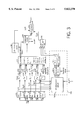
- FIG. 3 shows a block diagram of the compression apparatus of the present invention.
- FIG. 4 shows a table used by the classifier of FIG. 1 to generate the classification output signal band on power per band.
- FIG. 5A shows a table of the rearrangement performed by the wavelet transform and band shift decision circuit.
- FIGS. 5B-D shows a spectrum plot illustrating the operation of one aspect of the invention in accordance with the logic of FIG. 4 and FIG. 5A.
- FIG. 6A shows a block diagram of a transmitter in accordance with the present invention.
- FIG. 6B shows a block diagram of embodiments of a receiver system in accordance with the present invention.
- FIG. 6C shows a thresholding plot
- FIG. 7 shows a block diagram of a telephony embodiment.
- the spectra compression and decompression system and method of the present invention provide an economical way to transmit a signal, having a spectrum greater than 3.5 kHz bandwidth, over a telephone line.
- a signal having a spectrum greater than 3.5 kHz bandwidth
- high fidelity sound may be communicated over the present telephone system.
- Alternate embodiments can use the present invention in applications other than telephony.
- the present compression scheme can be used in any application where a signal must be compressed to a narrower bandwidth.
- a graph is provided illustrating the frequency location of speech phonemes, illustrating the ranges of spectrum where peak power of phonemes lies.
- the frequency band of speech ranges from 200 Hz to 8 kHz.
- Voiced speech such as "a”, “ee”, “i”, “u”, “oo”, “oh”, etc. occupy a lower band of the frequency band of speech, from approximately 200 Hz to 1.5 kHz.
- the unvoiced speech, consonants and combinations occupy the remainder, with simple consonants such as “k”, “l”, “m”, “n”, occupying from 1.5 kHz to 3.5 kHz, while unvoiced sounds such as "s”, "t”, “f”, “th”, “sh”, “ch”, and "c” occupy from 3.5 kHz to 8 kHz.
- FIG. 2 illustrates a frequency band transposition plot.
- the frequency band of speech including the subset of the frequency bandwidth of the telephone are broken into a plurality of discrete bands illustrated as Band A from 200-700 Hz, Band B from 700-1400 Hz, Band C from 1.4 kHz to 2.8 kHz and Band X from 2.8 kHz to 3.5 kHz, Bands A, B, C and X in combination comprising the frequency band of the telephone, plus Band D comprising from 3.5 kHz to 5.6 kHz, and Band E illustrated as 5.6 kHz to 11.2 kHz. All bands below or above these bands are ignored. As illustrated in FIG.
- the useful transposition range is Bands A, B and C.
- Bands X, D, and E are the range of frequencies which must be transposed for compression to occur.
- Band X is utilized as a codebook band to provide a coding signal for the code symbol which indicates what compression shift has occurred during the transmission compression process.
- a sharp sine-wave can be utilized for each bit of a binary code signal.
- three sharp sine-waves for example, one at 3 kHz, one at 3.1 kHz and one at 3.2 kHz, or a combination of the three, can be utilized to accommodate information of 8 code symbols having pre-defined meanings.
- the encoding and decoding systems of the transmitter and receiver must then utilize the same code book to indicate the compression and shifting process and therefore also the decompression and re-spreading process.
- FIG. 3 A block diagram, of a specific embodiment of the spectra compression system of the present invention is illustrated in FIG. 3.
- the input signal of the present invention is denoted as S(t).
- S(t) is a digitized voice signal spoken by a telephone user.
- S(t) therefore, has the bandwidth of human speech.
- the present invention is implemented in a digital signal processor (DSP).
- DSP digital signal processor
- the input voice signal is sampled at a frequency of 22,400 Hz (twice the highest bandpass filter frequency of 11,200 Hz) and digitized by an 11-bit analog to digital converter before being operated on by the present invention.
- S(t) is input to an anti-aliasing filter having a cut-off of 11,200 Hz to yield the bands illustrated in FIG. 1.
- S(t) is also input to a high pass filter having a cut-off of 200 Hz to filter out the very low frequencies.
- S(t) is input to an array of bandpass filters (101-105), each filter covering a different portion of the frequency spectrum.
- this array of bandpass filters (101-105) is comprised of five filters that have different passbands.
- the filters cover 200-700 Hz (101), 700-1400 Hz (102), 1400-2800 Hz (103), 2800-5600 Hz (104), and 5600-11,200 Hz (105).
- Each of these filters therefore, allows only the information contained within its respective frequency band to pass through to its output.
- these bands are subsequently referred to as A, B, C, D, and E respectively.
- the outputs of the bandpass filters, S A (t)-S E (t), are each input to a respective power detector (121-125).
- Each power detector (121-125) determines if there is an information signal in any of the respective filtered signals output from the bandpass filters (101-105).
- Each power detector (121-125) measures the power in its respective spectrum, such as by squaring the amplitude of the filtered signal and averaging these signals over a time interval of T. This power detection is exhibited by the equation: ##EQU1## where T is an interval of 20 msec. in the preferred embodiment. Other embodiments use other time intervals for averaging the power.
- the power detection signals, P A -P E are input to a respective one of a number of threshold comparators (131-135), one comparator for each power detector (121-125).
- the comparators (131-135) generate a signal indicating whether the detected power in each filtered signal, S A (t)-S E (t), is beyond a predetermined threshold.
- the predetermined threshold is 10% of the maximum power of the given band over a test run of 100 arbitrary words. Other embodiments use other thresholds.
- These decision signals are labeled Y/N(A), Y/N(B), Y/N(C), Y/N(D), and Y/N(E).
- these signals are a logical "1” if that respective signal is greater than the threshold.
- the comparator output signal is a logical "0” if that respective signal is below the predetermined threshold.
- An alternate embodiment uses only one power detector that is switched between the filtered signals S A (t)-S E (t). This embodiment also uses one threshold comparator that is coupled to the one power detector. Other embodiments use different quantities of power detectors and threshold comparators.
- Each of these decision signals are input to a classifier (175) that determines, from Y/N(A-E), if S(t) needs to be compressed.
- the classifier (175) uses the logic of the table illustrated in FIG. 4 to execute the shift, as set forth in the table of FIG. 5A to determine what is to be done to S(t) and can be implemented in hardware or software, such as using a DSP.
- the logic for providing a classifier output is illustrated in the table on the power in the band versus the classification code symbol or classifier output.
- the power in the band is denoted by a "P", such that "P A " denotes the power in Band A.
- the classifier outputs A, B1, B2, and B3 provide classification code symbol signal outputs. This is also designated a/b i .
- the power in Bands A, B, and C can be of any level, and are essentially don't cares. This is because even if the wavelet transform space parameter values in a band is non-empty, due to the sparseness of the wavelet transform in each band, there is still room for wavelet transform parameters from other bands to be shifted over.
- S(t) is operated on by the band shift process b 1 illustrated in the table of FIG. 5A.
- power in the band between 5,600 Hz and 11,200 Hz is greater than the threshold power level, indicating information in that band.
- the information must be shifted down to a lower band as will be discussed subsequently.
- the information in band D is shifted down prior to the shift down from band E.
- S(t) is operated on by the band shift process b 2 .
- This scenario indicates that there is information in band E and none in band D. The information in band E must be shifted down to a lower band to compress S(t).
- the classifier 175 of FIG. 3 uses the logic of FIG. 4 to cause the shifts and state flow of the logic shown in FIG. 5A.
- the classification signal generated by the classifier (175) is input to a code book bandpass filter (180) with a very sharp cut-off and having a pass band of 2800-3500 Hz, subsequently referred to as band X.
- This filter generates the code signal y x (t) that is coupled to the transmitter (196), and will be transmitted to the receiving unit to indicate to the receiving unit what shift operation was performed on S(t).
- the Conditional Switch (185) output is coupled to the Transmitter (196).
- the filtered outputs, S A (t), S B (t), S C (t), S D (t), and S E (t), are also input to a wavelet transform (WT) circuit (190-a) whose output is then passed to a thresholding circuit (190-b) which outputs only wavelet values above a predetermined threshold value to block (190-c) which is a band rearrangement circuit. Also input to this block (190-c) is a b i signal from the conditional switch (185).
- the wavelet transform circuit (190-a) uses b i to determine whether or not to perform wavelet transforms on signals S A-E (t). If b i is a "0", no transforms are performed.
- wavelet transforms are performed on S A-E (t) thereby creating the signals W A , W B , W C , W D , and W E respectively.
- Wavelet transforms are well known in the art as seen in the paper by Stephane G. Mallat, A Theory for Multiresolution Signal Decomposition: The Wavelet Representation, IEEE Transactions on Pattern Analysis and Machine Intelligence, Vol. 11, No. 7, July 1989, incorporated herein by reference.
- FIG. 5 is exemplary of one case.
- the band rearrangement circuit (190-c) first shifts the spectrum of the output of both bands A and B into band A by compressing the spectrum of bands A and B by taking advantage of the property of WT of speech in narrow bands (such as in the present example) that if there is significant energy in the high frequencies (e.g. Bands D, E) then the WT parameters in Band A or B, even if they exist above a reasonable threshold value, they occupy only a narrow section of the WT range at that band, such that there is sufficient unused band to shift WT parameters into it from a higher band. In practice one can always then consider the energy in Band A to lie in the lower or higher half of the WT of that band.
- FIGS. 5B-D a transform plot for wavelets illustrating the wavelet transform plots for Band B (FIG. 5B), and Band A (FIG. 5C) before the shift is performed, with FIG. 5D illustrating Band A after the shift is performed.
- the system of the present invention checks the wavelet transform space as illustrated in FIG. 5C to determine which half of the space the wavelet transforms for that band are predominantly present in.
- the wavelet transform parameter numbers for Band A before the shift are in the lower half of the wavelet transform parameter numbers comprising the range from zero to the wavelet transform parameter value maximum, illustrated with a threshold at the wavelet transform maximum divided by two. Since the upper half of the transform space of FIG.
- the wavelet transform parameter values of FIG. 5B representing the wavelet transform values in Band B are shifted by the system of the present invention to occupy the wavelet transform space for Band A which is not used by the wavelet transforms from Band A, resulting in a compressed signal in Band A representing both the wavelet transforms of Band A and the wavelet transforms of Band B as illustrated in FIG. 5D.
- W C can now be shifted to Band B, and W D can now be shifted to band B.
- W E is then shifted to band C.
- the selection for b i of which bands are mapped to which bands for compression has many options. However, the codebook on each end must be fore the same mapping option.
- W B is shifted to band A as in b 1 , then W C can be shifted into band B and W E can be shifted into W C . If b i is equal to b 3 , W B is shifted to band A as in the first two operations so that W C can be shifted to band B and W D can be shifted to band C.
- W A , W B , and W C are input to an IWT (Inverse Wavelet Transform stage (195) that generates the signal S b (t).
- This signal is the result of an inverse wavelet transform being performed on the three input signals.
- This transform is well known in the art as can be seen in the Mallat paper mentioned above.
- the IWT stage (195) is the inverse operation of the WT (190-a) stage.
- the signals S a (t), S b (t) and y x (t) are input to a transmitter (196).
- the transmitter outputs a signal S(t)+y x (t). If compression was not performed on the input signal the transmitter is simply transmitting the input signal, S(t), plus the code book signal, y x (t).
- the code book signal instructs the receiving unit that the information signal received has not been compressed and therefore does not need to be decompressed.
- S b (t) is transmitted along with y x (t).
- S a (t) is not transmitted as it is a null signal.
- the receiving unit uses y x (t) to decompress and reconstruct the original signal.
- An indication of which shifting operation was performed is stored in band X discussed above. This informs the receiving unit as to which shifting process was used on the input signal.
- the receiving unit then performs the reverse process, of that illustrated in the table of FIG. 5A, to decompress the received signal S(t).
- FIG. 6A a transmitter side "compression" apparatus block diagram and process state flow chart of the signal passing through the compression system is illustrated.
- FIG. 6A substantially corresponds to the WT and wavelet band rearrangement subsystem 190 of FIG. 3, with similarly numbered blocks corresponding exactly.
- the input signal S(t) is coupled to the bandpass filter array (105) to generate bandpass filter output signals S a , S b , S c , S d , S e , corresponding to the signals from each of the bandpass filters for Bands A, B, C, D, and E respectively. Responsive to the wavelet transform signal output generated by the conditional switch, or responsive to the classification output from the classifier (175) of FIG.
- the WT and wavelet band rearrangement subsystem (190) initiates wavelet transforms and band rearrangement.
- the wavelet transform circuitry (190) performs a wavelet transform on each of the signals S a -S e to generate wavelet transform parameters signal outputs W a -W e respectively, for each of the Bands A-E respectively.
- the wavelet transform outputs W a -W e are coupled and input to a thresholding subsystem (190b) which passes through and processes the wavelet transform outputs to generate a thresholded wavelet transform output for each of the bands, W a -W e . Only wavelet parameters exceeding the predetermined threshold are passed through and become part of the thresholded wavelet transform signals.
- the wavelet threshold levels are pre-defined values, and in a preferred embodiment are set separately for each of the bands.
- the thresholded wavelet transform parameter outputs are coupled as inputs to the band shifting and re-arrangement circuitry (190c), which operates pursuant to the logic of FIGS. 4 and 5A to effectuate band shifting in accordance therewith, and provides as outputs the band shifted and combined wavelet transform parameters W* a -W* c .
- These outputs are coupled to an inverse wavelet transform subsystem (195), which outputs compressed signals S a *, S b *, and S c * in Bands A, B, and C respectively. Additionally, as illustrated in FIG.
- the bandshifting sub-system (190c) also generates a code output signal to a Band X filter output, which Band X sub-system (180) is also coupled to a sine-wave generator.
- the code signal is used to generate three sine-waves within the Band X range which represent the code symbol for the code table entry. Using the three sine-wave signals permits code information representative of 8 code signals.
- the signal outputs for Bands A, B, C and X, Signals S* A , S* B , S* C , and CS are combined at sub-system (186) to provide the compressed signal S*(t) which lies entirely in Bands A, B, C, and X. These signals are coupled to transmitter circuitry as appropriate for modulation, further encoding, and transmission.
- FIG. 6B illustrates a block diagram of a receiver (decompressing) apparatus.
- This apparatus is comprised of a receiver (601) that receives the transmitted signal and demodulates it.
- the demodulated signal S*(t) is input to an array of band pass filters (602) for the bands A, B, C, and X as discussed above providing filter output signals S* A , S* B , and S* C , respectively.
- These signals S A *, S B *, and S C * (in the A, B, and C band) are input to a wavelet transform circuit (604) that performs the wavelet transform on these signals to provide receiver wavelet transform parameter outputs W A *, W B *, and W C * for Bands A, B, and C, respectively.
- the X-band output (612) of the X-band filter (602X) is input to a code classification circuit (603) to determine the code that was imbedded in the transmitted signal to provide a classification code signal (613).
- the code signal (613) is used by the Band Rearrangement Logic (605) to determine whether to respread the received signal and, if so, which parts of the band to move from-where to-where, in accordance with the code book decode logic and respreading logic as illustrated in the tables of FIGS. 4 and 5A and discussion thereof.
- the wavelet parameters are appropriately shifted from and to the proper bands to provide respread wavelet outputs W A to W E for Bands A-E, respectively, forming the respread wavelet signal.
- the respread wavelet signal is operated on by an inverse wavelet transform system (606) that transforms the wavelet domain signals into W A , W B , W C , W D , and W E decompressed time domain signals S A , S B , S C , S D , and S E , respectively, which time domain signals are summed by the summing circuit (610) to provide a reconstructed hi-fi signal S(t) representative of the original hi-fi signal S(t).
- FIG. 6C illustrates the process of thresholding as described with reference to FIG. 6A thresholding subsystem (190b).
- the Band A wavelet transform parameter space is illustrated before thresholding and after thresholding.
- the value of the wavelet transform parameter numbers which exceed the threshold for those major parameters X, Y, and Z remain constant before and after thresholding.
- the drawing in FIG. 6C illustrates wavelet transform parameter amplitude for wavelet transform W A (before thresholding) and W A (the wavelet transform output after thresholding).
- W A before thresholding
- W A the wavelet transform output after thresholding
- the inverse wavelet transform of the thresholded wavelet transform output W A is substantially equal to the inverse wavelet transform of the non-thresholded wavelet transform output (W A ), except for an insignificant error (e.g. less than 1%).
- the thresholding permits more effective band-shifting operation, while introducing no significant error problem.
- the voice signal (1001) is coupled to a microphone and amplifier subsystem (1010), which provides a signal output to a compression subsystem (1020), which operates in accordance with the present invention and teachings herein to provide a compressed and band shifted signal output (for example, having a 3.5 kHz bandwidth) which is coupled to the transmitter (1030) to provide an output over the telephone lines.
- a receiver system (1600) on the receiving telephone side receives the transmitted signal from the transmitter (1030) which is coupled to a receiver (1040) (which in some embodiments reverses any encoding or modulating done by the transmitter) to recover the 3.5 kHz compressed signal.
- a decompression subsystem (1050) in accordance with the present invention, decompresses and re-spreads the compressed signal responsive to the compressed signal including the code book signal to provide a high-fi signal output (1101) which is coupled to an amplifier and speaker (1060) which provides a voice sound output for the telephone's user such as through the ear piece speaker or speaker of the phone.
- each telephone is comprised of a compression and transmission system (1500) and a receiver and decompression system (1600) to permit bi-directional communication.
- the present invention also finds application in many areas in addition to and outside of telephony, and can also be expanded beyond its application to only speech, by selection of appropriate bands of thresholds and code book parameters.
- the above described embodiment of the invention takes advantage of the properties of speech phonemes whose energy is well defined in a limited and narrow frequency band that are unique to each speech phoneme. It also utilizes the sparseness properties of discrete wavelet transforms and of the filter bank nature of these transforms. These properties allow that compression as above is possible with almost no loss of information especially since it is performed in each of only a very few frequency bands, but where each such band pass filtered band is treated separately from the others.
- the limited number of frequency bands also allows for a simple code book to store and transmit the exact spectral location of each wavelet transform value before and after its shift from a higher frequency band to a lower one for compression purposes and vice versa for decompression.
Abstract
Description
Claims (34)
Priority Applications (1)
| Application Number | Priority Date | Filing Date | Title |
|---|---|---|---|
| US08/632,914 US5822370A (en) | 1996-04-16 | 1996-04-16 | Compression/decompression for preservation of high fidelity speech quality at low bandwidth |
Applications Claiming Priority (1)
| Application Number | Priority Date | Filing Date | Title |
|---|---|---|---|
| US08/632,914 US5822370A (en) | 1996-04-16 | 1996-04-16 | Compression/decompression for preservation of high fidelity speech quality at low bandwidth |
Publications (1)
| Publication Number | Publication Date |
|---|---|
| US5822370A true US5822370A (en) | 1998-10-13 |
Family
ID=24537501
Family Applications (1)
| Application Number | Title | Priority Date | Filing Date |
|---|---|---|---|
| US08/632,914 Expired - Fee Related US5822370A (en) | 1996-04-16 | 1996-04-16 | Compression/decompression for preservation of high fidelity speech quality at low bandwidth |
Country Status (1)
| Country | Link |
|---|---|
| US (1) | US5822370A (en) |
Cited By (36)
| Publication number | Priority date | Publication date | Assignee | Title |
|---|---|---|---|---|
| US6009386A (en) * | 1997-11-28 | 1999-12-28 | Nortel Networks Corporation | Speech playback speed change using wavelet coding, preferably sub-band coding |
| US6292054B1 (en) * | 1999-11-19 | 2001-09-18 | Lucent Technologies Inc. | System and method for producing an amplified signal |
| US6311155B1 (en) | 2000-02-04 | 2001-10-30 | Hearing Enhancement Company Llc | Use of voice-to-remaining audio (VRA) in consumer applications |
| US6351733B1 (en) | 2000-03-02 | 2002-02-26 | Hearing Enhancement Company, Llc | Method and apparatus for accommodating primary content audio and secondary content remaining audio capability in the digital audio production process |
| US6442278B1 (en) | 1999-06-15 | 2002-08-27 | Hearing Enhancement Company, Llc | Voice-to-remaining audio (VRA) interactive center channel downmix |
| US6654189B1 (en) * | 1998-04-16 | 2003-11-25 | Sony Corporation | Digital-signal processing apparatus capable of adjusting the amplitude of a digital signal |
| US20030223491A1 (en) * | 2002-05-29 | 2003-12-04 | Wreschner Kenneth Solomon | Method and apparatus for adaptive signal compression |
| US6680972B1 (en) * | 1997-06-10 | 2004-01-20 | Coding Technologies Sweden Ab | Source coding enhancement using spectral-band replication |
| US20040049379A1 (en) * | 2002-09-04 | 2004-03-11 | Microsoft Corporation | Multi-channel audio encoding and decoding |
| US20040096065A1 (en) * | 2000-05-26 | 2004-05-20 | Vaudrey Michael A. | Voice-to-remaining audio (VRA) interactive center channel downmix |
| WO2004066501A2 (en) * | 2003-01-17 | 2004-08-05 | Digital Compression Technology, Lp | Coding system for minimizing digital data bandwidth |
| US20050185732A1 (en) * | 2004-02-25 | 2005-08-25 | Nokia Corporation | Multiscale wireless communication |
| US6985594B1 (en) | 1999-06-15 | 2006-01-10 | Hearing Enhancement Co., Llc. | Voice-to-remaining audio (VRA) interactive hearing aid and auxiliary equipment |
| US6988013B1 (en) * | 1998-11-13 | 2006-01-17 | Sony Corporation | Method and apparatus for audio signal processing |
| US20060241938A1 (en) * | 2005-04-20 | 2006-10-26 | Hetherington Phillip A | System for improving speech intelligibility through high frequency compression |
| US20060247922A1 (en) * | 2005-04-20 | 2006-11-02 | Phillip Hetherington | System for improving speech quality and intelligibility |
| US20060270373A1 (en) * | 2005-05-27 | 2006-11-30 | Nasaco Electronics (Hong Kong) Ltd. | In-flight entertainment wireless audio transmitter/receiver system |
| US20070174063A1 (en) * | 2006-01-20 | 2007-07-26 | Microsoft Corporation | Shape and scale parameters for extended-band frequency coding |
| US20070174050A1 (en) * | 2005-04-20 | 2007-07-26 | Xueman Li | High frequency compression integration |
| US20070174062A1 (en) * | 2006-01-20 | 2007-07-26 | Microsoft Corporation | Complex-transform channel coding with extended-band frequency coding |
| US20070172071A1 (en) * | 2006-01-20 | 2007-07-26 | Microsoft Corporation | Complex transforms for multi-channel audio |
| US20070185706A1 (en) * | 2001-12-14 | 2007-08-09 | Microsoft Corporation | Quality improvement techniques in an audio encoder |
| US7266501B2 (en) | 2000-03-02 | 2007-09-04 | Akiba Electronics Institute Llc | Method and apparatus for accommodating primary content audio and secondary content remaining audio capability in the digital audio production process |
| US20080021704A1 (en) * | 2002-09-04 | 2008-01-24 | Microsoft Corporation | Quantization and inverse quantization for audio |
| US7415120B1 (en) | 1998-04-14 | 2008-08-19 | Akiba Electronics Institute Llc | User adjustable volume control that accommodates hearing |
| US7483758B2 (en) | 2000-05-23 | 2009-01-27 | Coding Technologies Sweden Ab | Spectral translation/folding in the subband domain |
| US7539612B2 (en) | 2005-07-15 | 2009-05-26 | Microsoft Corporation | Coding and decoding scale factor information |
| US20090245539A1 (en) * | 1998-04-14 | 2009-10-01 | Vaudrey Michael A | User adjustable volume control that accommodates hearing |
| US7653255B2 (en) | 2004-06-02 | 2010-01-26 | Adobe Systems Incorporated | Image region of interest encoding |
| US20100318368A1 (en) * | 2002-09-04 | 2010-12-16 | Microsoft Corporation | Quantization and inverse quantization for audio |
| US7930171B2 (en) | 2001-12-14 | 2011-04-19 | Microsoft Corporation | Multi-channel audio encoding/decoding with parametric compression/decompression and weight factors |
| US8645127B2 (en) | 2004-01-23 | 2014-02-04 | Microsoft Corporation | Efficient coding of digital media spectral data using wide-sense perceptual similarity |
| US8645146B2 (en) | 2007-06-29 | 2014-02-04 | Microsoft Corporation | Bitstream syntax for multi-process audio decoding |
| US8935156B2 (en) | 1999-01-27 | 2015-01-13 | Dolby International Ab | Enhancing performance of spectral band replication and related high frequency reconstruction coding |
| US20180350378A1 (en) * | 2017-06-01 | 2018-12-06 | Sorenson Ip Holdings, Llc | Detecting and reducing feedback |
| CN108986839A (en) * | 2017-06-01 | 2018-12-11 | 瑟恩森知识产权控股有限公司 | Reduce the noise in audio signal |
Citations (9)
| Publication number | Priority date | Publication date | Assignee | Title |
|---|---|---|---|---|
| US4048443A (en) * | 1975-12-12 | 1977-09-13 | Bell Telephone Laboratories, Incorporated | Digital speech communication system for minimizing quantizing noise |
| US4370524A (en) * | 1977-11-22 | 1983-01-25 | Victor Company Of Japan, Ltd. | Circuit for time compression and expansion of audio signals |
| US4866777A (en) * | 1984-11-09 | 1989-09-12 | Alcatel Usa Corporation | Apparatus for extracting features from a speech signal |
| US5115240A (en) * | 1989-09-26 | 1992-05-19 | Sony Corporation | Method and apparatus for encoding voice signals divided into a plurality of frequency bands |
| US5617507A (en) * | 1991-11-06 | 1997-04-01 | Korea Telecommunication Authority | Speech segment coding and pitch control methods for speech synthesis systems |
| US5621850A (en) * | 1990-05-28 | 1997-04-15 | Matsushita Electric Industrial Co., Ltd. | Speech signal processing apparatus for cutting out a speech signal from a noisy speech signal |
| US5625743A (en) * | 1994-10-07 | 1997-04-29 | Motorola, Inc. | Determining a masking level for a subband in a subband audio encoder |
| US5673364A (en) * | 1993-12-01 | 1997-09-30 | The Dsp Group Ltd. | System and method for compression and decompression of audio signals |
| US5719998A (en) * | 1995-06-12 | 1998-02-17 | S3, Incorporated | Partitioned decompression of audio data using audio decoder engine for computationally intensive processing |
-
1996
- 1996-04-16 US US08/632,914 patent/US5822370A/en not_active Expired - Fee Related
Patent Citations (9)
| Publication number | Priority date | Publication date | Assignee | Title |
|---|---|---|---|---|
| US4048443A (en) * | 1975-12-12 | 1977-09-13 | Bell Telephone Laboratories, Incorporated | Digital speech communication system for minimizing quantizing noise |
| US4370524A (en) * | 1977-11-22 | 1983-01-25 | Victor Company Of Japan, Ltd. | Circuit for time compression and expansion of audio signals |
| US4866777A (en) * | 1984-11-09 | 1989-09-12 | Alcatel Usa Corporation | Apparatus for extracting features from a speech signal |
| US5115240A (en) * | 1989-09-26 | 1992-05-19 | Sony Corporation | Method and apparatus for encoding voice signals divided into a plurality of frequency bands |
| US5621850A (en) * | 1990-05-28 | 1997-04-15 | Matsushita Electric Industrial Co., Ltd. | Speech signal processing apparatus for cutting out a speech signal from a noisy speech signal |
| US5617507A (en) * | 1991-11-06 | 1997-04-01 | Korea Telecommunication Authority | Speech segment coding and pitch control methods for speech synthesis systems |
| US5673364A (en) * | 1993-12-01 | 1997-09-30 | The Dsp Group Ltd. | System and method for compression and decompression of audio signals |
| US5625743A (en) * | 1994-10-07 | 1997-04-29 | Motorola, Inc. | Determining a masking level for a subband in a subband audio encoder |
| US5719998A (en) * | 1995-06-12 | 1998-02-17 | S3, Incorporated | Partitioned decompression of audio data using audio decoder engine for computationally intensive processing |
Non-Patent Citations (2)
| Title |
|---|
| Mallat, "A Theory for Multiresolution Signal Decomposition: The Wavelet Representation", IEEE Transactions On Pattern Analysis and Machine Intelligence, vol. II, No. 7, Jul., 1989. |
| Mallat, A Theory for Multiresolution Signal Decomposition: The Wavelet Representation , IEEE Transactions On Pattern Analysis and Machine Intelligence , vol. II, No. 7, Jul., 1989. * |
Cited By (108)
| Publication number | Priority date | Publication date | Assignee | Title |
|---|---|---|---|---|
| US6680972B1 (en) * | 1997-06-10 | 2004-01-20 | Coding Technologies Sweden Ab | Source coding enhancement using spectral-band replication |
| US7328162B2 (en) | 1997-06-10 | 2008-02-05 | Coding Technologies Ab | Source coding enhancement using spectral-band replication |
| US7283955B2 (en) | 1997-06-10 | 2007-10-16 | Coding Technologies Ab | Source coding enhancement using spectral-band replication |
| CN1308916C (en) * | 1997-06-10 | 2007-04-04 | 编码技术股份公司 | Source coding enhancement using spectral-band replication |
| US6925116B2 (en) | 1997-06-10 | 2005-08-02 | Coding Technologies Ab | Source coding enhancement using spectral-band replication |
| US20040125878A1 (en) * | 1997-06-10 | 2004-07-01 | Coding Technologies Sweden Ab | Source coding enhancement using spectral-band replication |
| US20040078194A1 (en) * | 1997-06-10 | 2004-04-22 | Coding Technologies Sweden Ab | Source coding enhancement using spectral-band replication |
| US20040078205A1 (en) * | 1997-06-10 | 2004-04-22 | Coding Technologies Sweden Ab | Source coding enhancement using spectral-band replication |
| US6009386A (en) * | 1997-11-28 | 1999-12-28 | Nortel Networks Corporation | Speech playback speed change using wavelet coding, preferably sub-band coding |
| US7415120B1 (en) | 1998-04-14 | 2008-08-19 | Akiba Electronics Institute Llc | User adjustable volume control that accommodates hearing |
| US20050232445A1 (en) * | 1998-04-14 | 2005-10-20 | Hearing Enhancement Company Llc | Use of voice-to-remaining audio (VRA) in consumer applications |
| US8170884B2 (en) | 1998-04-14 | 2012-05-01 | Akiba Electronics Institute Llc | Use of voice-to-remaining audio (VRA) in consumer applications |
| US8284960B2 (en) | 1998-04-14 | 2012-10-09 | Akiba Electronics Institute, Llc | User adjustable volume control that accommodates hearing |
| US20090245539A1 (en) * | 1998-04-14 | 2009-10-01 | Vaudrey Michael A | User adjustable volume control that accommodates hearing |
| US20080130924A1 (en) * | 1998-04-14 | 2008-06-05 | Vaudrey Michael A | Use of voice-to-remaining audio (vra) in consumer applications |
| US7337111B2 (en) | 1998-04-14 | 2008-02-26 | Akiba Electronics Institute, Llc | Use of voice-to-remaining audio (VRA) in consumer applications |
| US20020013698A1 (en) * | 1998-04-14 | 2002-01-31 | Vaudrey Michael A. | Use of voice-to-remaining audio (VRA) in consumer applications |
| US6912501B2 (en) | 1998-04-14 | 2005-06-28 | Hearing Enhancement Company Llc | Use of voice-to-remaining audio (VRA) in consumer applications |
| US6654189B1 (en) * | 1998-04-16 | 2003-11-25 | Sony Corporation | Digital-signal processing apparatus capable of adjusting the amplitude of a digital signal |
| US6988013B1 (en) * | 1998-11-13 | 2006-01-17 | Sony Corporation | Method and apparatus for audio signal processing |
| US8935156B2 (en) | 1999-01-27 | 2015-01-13 | Dolby International Ab | Enhancing performance of spectral band replication and related high frequency reconstruction coding |
| US9245533B2 (en) | 1999-01-27 | 2016-01-26 | Dolby International Ab | Enhancing performance of spectral band replication and related high frequency reconstruction coding |
| US6985594B1 (en) | 1999-06-15 | 2006-01-10 | Hearing Enhancement Co., Llc. | Voice-to-remaining audio (VRA) interactive hearing aid and auxiliary equipment |
| US6442278B1 (en) | 1999-06-15 | 2002-08-27 | Hearing Enhancement Company, Llc | Voice-to-remaining audio (VRA) interactive center channel downmix |
| US6650755B2 (en) | 1999-06-15 | 2003-11-18 | Hearing Enhancement Company, Llc | Voice-to-remaining audio (VRA) interactive center channel downmix |
| USRE42737E1 (en) | 1999-06-15 | 2011-09-27 | Akiba Electronics Institute Llc | Voice-to-remaining audio (VRA) interactive hearing aid and auxiliary equipment |
| AU769523B2 (en) * | 1999-11-19 | 2004-01-29 | Lucent Technologies Inc. | System and method for producing an amplified signal |
| US6292054B1 (en) * | 1999-11-19 | 2001-09-18 | Lucent Technologies Inc. | System and method for producing an amplified signal |
| US6624694B2 (en) * | 1999-11-19 | 2003-09-23 | Lucent Technologies Inc. | System and method for producing an amplified signal |
| US6311155B1 (en) | 2000-02-04 | 2001-10-30 | Hearing Enhancement Company Llc | Use of voice-to-remaining audio (VRA) in consumer applications |
| US7266501B2 (en) | 2000-03-02 | 2007-09-04 | Akiba Electronics Institute Llc | Method and apparatus for accommodating primary content audio and secondary content remaining audio capability in the digital audio production process |
| US8108220B2 (en) | 2000-03-02 | 2012-01-31 | Akiba Electronics Institute Llc | Techniques for accommodating primary content (pure voice) audio and secondary content remaining audio capability in the digital audio production process |
| US6351733B1 (en) | 2000-03-02 | 2002-02-26 | Hearing Enhancement Company, Llc | Method and apparatus for accommodating primary content audio and secondary content remaining audio capability in the digital audio production process |
| US20080059160A1 (en) * | 2000-03-02 | 2008-03-06 | Akiba Electronics Institute Llc | Techniques for accommodating primary content (pure voice) audio and secondary content remaining audio capability in the digital audio production process |
| US6772127B2 (en) | 2000-03-02 | 2004-08-03 | Hearing Enhancement Company, Llc | Method and apparatus for accommodating primary content audio and secondary content remaining audio capability in the digital audio production process |
| US7680552B2 (en) | 2000-05-23 | 2010-03-16 | Coding Technologies Sweden Ab | Spectral translation/folding in the subband domain |
| US9691400B1 (en) | 2000-05-23 | 2017-06-27 | Dolby International Ab | Spectral translation/folding in the subband domain |
| US9697841B2 (en) | 2000-05-23 | 2017-07-04 | Dolby International Ab | Spectral translation/folding in the subband domain |
| US10008213B2 (en) | 2000-05-23 | 2018-06-26 | Dolby International Ab | Spectral translation/folding in the subband domain |
| US9245534B2 (en) | 2000-05-23 | 2016-01-26 | Dolby International Ab | Spectral translation/folding in the subband domain |
| US10699724B2 (en) | 2000-05-23 | 2020-06-30 | Dolby International Ab | Spectral translation/folding in the subband domain |
| US10311882B2 (en) | 2000-05-23 | 2019-06-04 | Dolby International Ab | Spectral translation/folding in the subband domain |
| US8412365B2 (en) | 2000-05-23 | 2013-04-02 | Dolby International Ab | Spectral translation/folding in the subband domain |
| US9691402B1 (en) | 2000-05-23 | 2017-06-27 | Dolby International Ab | Spectral translation/folding in the subband domain |
| US9786290B2 (en) | 2000-05-23 | 2017-10-10 | Dolby International Ab | Spectral translation/folding in the subband domain |
| US9691399B1 (en) | 2000-05-23 | 2017-06-27 | Dolby International Ab | Spectral translation/folding in the subband domain |
| US7483758B2 (en) | 2000-05-23 | 2009-01-27 | Coding Technologies Sweden Ab | Spectral translation/folding in the subband domain |
| US20090041111A1 (en) * | 2000-05-23 | 2009-02-12 | Coding Technologies Sweden Ab | spectral translation/folding in the subband domain |
| US8543232B2 (en) | 2000-05-23 | 2013-09-24 | Dolby International Ab | Spectral translation/folding in the subband domain |
| US20100211399A1 (en) * | 2000-05-23 | 2010-08-19 | Lars Liljeryd | Spectral Translation/Folding in the Subband Domain |
| US9691401B1 (en) | 2000-05-23 | 2017-06-27 | Dolby International Ab | Spectral translation/folding in the subband domain |
| US9691403B1 (en) | 2000-05-23 | 2017-06-27 | Dolby International Ab | Spectral translation/folding in the subband domain |
| US20040096065A1 (en) * | 2000-05-26 | 2004-05-20 | Vaudrey Michael A. | Voice-to-remaining audio (VRA) interactive center channel downmix |
| US8554569B2 (en) | 2001-12-14 | 2013-10-08 | Microsoft Corporation | Quality improvement techniques in an audio encoder |
| US8805696B2 (en) | 2001-12-14 | 2014-08-12 | Microsoft Corporation | Quality improvement techniques in an audio encoder |
| US20070185706A1 (en) * | 2001-12-14 | 2007-08-09 | Microsoft Corporation | Quality improvement techniques in an audio encoder |
| US8428943B2 (en) | 2001-12-14 | 2013-04-23 | Microsoft Corporation | Quantization matrices for digital audio |
| US9443525B2 (en) | 2001-12-14 | 2016-09-13 | Microsoft Technology Licensing, Llc | Quality improvement techniques in an audio encoder |
| US9305558B2 (en) | 2001-12-14 | 2016-04-05 | Microsoft Technology Licensing, Llc | Multi-channel audio encoding/decoding with parametric compression/decompression and weight factors |
| US7917369B2 (en) | 2001-12-14 | 2011-03-29 | Microsoft Corporation | Quality improvement techniques in an audio encoder |
| US7930171B2 (en) | 2001-12-14 | 2011-04-19 | Microsoft Corporation | Multi-channel audio encoding/decoding with parametric compression/decompression and weight factors |
| US7277482B2 (en) * | 2002-05-29 | 2007-10-02 | General Dynamics C4 Systems, Inc. | Method and apparatus for adaptive signal compression |
| US20030223491A1 (en) * | 2002-05-29 | 2003-12-04 | Wreschner Kenneth Solomon | Method and apparatus for adaptive signal compression |
| US8620674B2 (en) * | 2002-09-04 | 2013-12-31 | Microsoft Corporation | Multi-channel audio encoding and decoding |
| US8255234B2 (en) | 2002-09-04 | 2012-08-28 | Microsoft Corporation | Quantization and inverse quantization for audio |
| US8069052B2 (en) | 2002-09-04 | 2011-11-29 | Microsoft Corporation | Quantization and inverse quantization for audio |
| US20040049379A1 (en) * | 2002-09-04 | 2004-03-11 | Microsoft Corporation | Multi-channel audio encoding and decoding |
| US8099292B2 (en) | 2002-09-04 | 2012-01-17 | Microsoft Corporation | Multi-channel audio encoding and decoding |
| US7801735B2 (en) | 2002-09-04 | 2010-09-21 | Microsoft Corporation | Compressing and decompressing weight factors using temporal prediction for audio data |
| US7860720B2 (en) | 2002-09-04 | 2010-12-28 | Microsoft Corporation | Multi-channel audio encoding and decoding with different window configurations |
| US20080021704A1 (en) * | 2002-09-04 | 2008-01-24 | Microsoft Corporation | Quantization and inverse quantization for audio |
| US8386269B2 (en) | 2002-09-04 | 2013-02-26 | Microsoft Corporation | Multi-channel audio encoding and decoding |
| US8069050B2 (en) | 2002-09-04 | 2011-11-29 | Microsoft Corporation | Multi-channel audio encoding and decoding |
| US8255230B2 (en) | 2002-09-04 | 2012-08-28 | Microsoft Corporation | Multi-channel audio encoding and decoding |
| US7502743B2 (en) * | 2002-09-04 | 2009-03-10 | Microsoft Corporation | Multi-channel audio encoding and decoding with multi-channel transform selection |
| US20100318368A1 (en) * | 2002-09-04 | 2010-12-16 | Microsoft Corporation | Quantization and inverse quantization for audio |
| WO2004066501A3 (en) * | 2003-01-17 | 2006-12-21 | Digital Compression Technology | Coding system for minimizing digital data bandwidth |
| US20040208271A1 (en) * | 2003-01-17 | 2004-10-21 | Gruenberg Elliot L. | Coding system for minimizing digital data bandwidth |
| WO2004066501A2 (en) * | 2003-01-17 | 2004-08-05 | Digital Compression Technology, Lp | Coding system for minimizing digital data bandwidth |
| US7336747B2 (en) | 2003-01-17 | 2008-02-26 | Digital Compression Technology | Coding system for minimizing digital data bandwidth |
| US8645127B2 (en) | 2004-01-23 | 2014-02-04 | Microsoft Corporation | Efficient coding of digital media spectral data using wide-sense perceptual similarity |
| US20050185732A1 (en) * | 2004-02-25 | 2005-08-25 | Nokia Corporation | Multiscale wireless communication |
| US7680208B2 (en) * | 2004-02-25 | 2010-03-16 | Nokia Corporation | Multiscale wireless communication |
| US7653255B2 (en) | 2004-06-02 | 2010-01-26 | Adobe Systems Incorporated | Image region of interest encoding |
| US20060247922A1 (en) * | 2005-04-20 | 2006-11-02 | Phillip Hetherington | System for improving speech quality and intelligibility |
| US20070174050A1 (en) * | 2005-04-20 | 2007-07-26 | Xueman Li | High frequency compression integration |
| US8086451B2 (en) * | 2005-04-20 | 2011-12-27 | Qnx Software Systems Co. | System for improving speech intelligibility through high frequency compression |
| US8219389B2 (en) | 2005-04-20 | 2012-07-10 | Qnx Software Systems Limited | System for improving speech intelligibility through high frequency compression |
| US20060241938A1 (en) * | 2005-04-20 | 2006-10-26 | Hetherington Phillip A | System for improving speech intelligibility through high frequency compression |
| US7813931B2 (en) * | 2005-04-20 | 2010-10-12 | QNX Software Systems, Co. | System for improving speech quality and intelligibility with bandwidth compression/expansion |
| US8249861B2 (en) * | 2005-04-20 | 2012-08-21 | Qnx Software Systems Limited | High frequency compression integration |
| US20060270373A1 (en) * | 2005-05-27 | 2006-11-30 | Nasaco Electronics (Hong Kong) Ltd. | In-flight entertainment wireless audio transmitter/receiver system |
| US7539612B2 (en) | 2005-07-15 | 2009-05-26 | Microsoft Corporation | Coding and decoding scale factor information |
| US20070172071A1 (en) * | 2006-01-20 | 2007-07-26 | Microsoft Corporation | Complex transforms for multi-channel audio |
| US9105271B2 (en) | 2006-01-20 | 2015-08-11 | Microsoft Technology Licensing, Llc | Complex-transform channel coding with extended-band frequency coding |
| US7831434B2 (en) | 2006-01-20 | 2010-11-09 | Microsoft Corporation | Complex-transform channel coding with extended-band frequency coding |
| US20070174062A1 (en) * | 2006-01-20 | 2007-07-26 | Microsoft Corporation | Complex-transform channel coding with extended-band frequency coding |
| US20070174063A1 (en) * | 2006-01-20 | 2007-07-26 | Microsoft Corporation | Shape and scale parameters for extended-band frequency coding |
| US7953604B2 (en) | 2006-01-20 | 2011-05-31 | Microsoft Corporation | Shape and scale parameters for extended-band frequency coding |
| US8190425B2 (en) | 2006-01-20 | 2012-05-29 | Microsoft Corporation | Complex cross-correlation parameters for multi-channel audio |
| US9349376B2 (en) | 2007-06-29 | 2016-05-24 | Microsoft Technology Licensing, Llc | Bitstream syntax for multi-process audio decoding |
| US9741354B2 (en) | 2007-06-29 | 2017-08-22 | Microsoft Technology Licensing, Llc | Bitstream syntax for multi-process audio decoding |
| US8645146B2 (en) | 2007-06-29 | 2014-02-04 | Microsoft Corporation | Bitstream syntax for multi-process audio decoding |
| US9026452B2 (en) | 2007-06-29 | 2015-05-05 | Microsoft Technology Licensing, Llc | Bitstream syntax for multi-process audio decoding |
| US20180350378A1 (en) * | 2017-06-01 | 2018-12-06 | Sorenson Ip Holdings, Llc | Detecting and reducing feedback |
| CN108986839A (en) * | 2017-06-01 | 2018-12-11 | 瑟恩森知识产权控股有限公司 | Reduce the noise in audio signal |
| US10504538B2 (en) * | 2017-06-01 | 2019-12-10 | Sorenson Ip Holdings, Llc | Noise reduction by application of two thresholds in each frequency band in audio signals |
| US10540983B2 (en) * | 2017-06-01 | 2020-01-21 | Sorenson Ip Holdings, Llc | Detecting and reducing feedback |
Similar Documents
| Publication | Publication Date | Title |
|---|---|---|
| US5822370A (en) | Compression/decompression for preservation of high fidelity speech quality at low bandwidth | |
| KR100242864B1 (en) | Digital signal coder and the method | |
| US5072308A (en) | Communication signal compression system and method | |
| JP3721582B2 (en) | Signal encoding apparatus and method, and signal decoding apparatus and method | |
| US5353374A (en) | Low bit rate voice transmission for use in a noisy environment | |
| US6263312B1 (en) | Audio compression and decompression employing subband decomposition of residual signal and distortion reduction | |
| RU2144261C1 (en) | Transmitting system depending for its operation on different coding | |
| US5068899A (en) | Transmission of wideband speech signals | |
| CA2206129C (en) | Method and apparatus for applying waveform prediction to subbands of a perceptual coding system | |
| US5982817A (en) | Transmission system utilizing different coding principles | |
| US5930750A (en) | Adaptive subband scaling method and apparatus for quantization bit allocation in variable length perceptual coding | |
| EP0713295A1 (en) | Method and device for encoding information, method and device for decoding information, information transmitting method, and information recording medium | |
| JPH07336232A (en) | Method and device for coding information, method and device for decoding information and information recording medium | |
| WO1985000686A1 (en) | Apparatus and methods for coding, decoding, analyzing and synthesizing a signal | |
| US5054073A (en) | Voice analysis and synthesis dependent upon a silence decision | |
| EP0480083B1 (en) | Communication signal compression system and method | |
| KR100352351B1 (en) | Information encoding method and apparatus and Information decoding method and apparatus | |
| JP3189401B2 (en) | Audio data encoding method and audio data encoding device | |
| JP3685823B2 (en) | Signal encoding method and apparatus, and signal decoding method and apparatus | |
| JP3827720B2 (en) | Transmission system using differential coding principle | |
| JPH09230894A (en) | Speech companding device and method therefor | |
| Carnero et al. | Perceptual coding of speech using a fast wavelet packet transform algorithm | |
| JP2004534421A (en) | Method and apparatus for compressing analog and digital signals and data | |
| JP3465698B2 (en) | Signal decoding method and apparatus | |
| JP3217237B2 (en) | Loop type band division audio conference circuit |
Legal Events
| Date | Code | Title | Description |
|---|---|---|---|
| AS | Assignment |
Owner name: NEWCOM, INC., CALIFORNIA Free format text: ASSIGNMENT OF ASSIGNORS INTEREST;ASSIGNOR:AURA SYSTEMS, INC.;REEL/FRAME:009314/0480 Effective date: 19980709 |
|
| AS | Assignment |
Owner name: SITRICK & SITRICK, ILLINOIS Free format text: ASSIGNMENT OF ASSIGNORS INTEREST;ASSIGNOR:AURA SYSTEMS, INC.;REEL/FRAME:010881/0144 Effective date: 19991209 |
|
| FEPP | Fee payment procedure |
Free format text: PAYER NUMBER DE-ASSIGNED (ORIGINAL EVENT CODE: RMPN); ENTITY STATUS OF PATENT OWNER: SMALL ENTITY Free format text: PAYOR NUMBER ASSIGNED (ORIGINAL EVENT CODE: ASPN); ENTITY STATUS OF PATENT OWNER: SMALL ENTITY |
|
| FPAY | Fee payment |
Year of fee payment: 4 |
|
| FPAY | Fee payment |
Year of fee payment: 8 |
|
| AS | Assignment |
Owner name: SITRICK, DAVID H., ILLINOIS Free format text: ASSIGNMENT OF ASSIGNORS INTEREST;ASSIGNOR:SITRICK & SITRICK;REEL/FRAME:021439/0608 Effective date: 20080822 |
|
| REMI | Maintenance fee reminder mailed | ||
| LAPS | Lapse for failure to pay maintenance fees | ||
| STCH | Information on status: patent discontinuation |
Free format text: PATENT EXPIRED DUE TO NONPAYMENT OF MAINTENANCE FEES UNDER 37 CFR 1.362 |
|
| FP | Lapsed due to failure to pay maintenance fee |
Effective date: 20101013 |