US5752923A - Biopsy instrument with handle and needle set - Google Patents
Biopsy instrument with handle and needle set Download PDFInfo
- Publication number
- US5752923A US5752923A US08/669,039 US66903996A US5752923A US 5752923 A US5752923 A US 5752923A US 66903996 A US66903996 A US 66903996A US 5752923 A US5752923 A US 5752923A
- Authority
- US
- United States
- Prior art keywords
- needle
- hub
- handle
- trigger
- drive mechanism
- Prior art date
- Legal status (The legal status is an assumption and is not a legal conclusion. Google has not performed a legal analysis and makes no representation as to the accuracy of the status listed.)
- Expired - Lifetime
Links
Images


Classifications
-
- A—HUMAN NECESSITIES
- A61—MEDICAL OR VETERINARY SCIENCE; HYGIENE
- A61B—DIAGNOSIS; SURGERY; IDENTIFICATION
- A61B10/00—Other methods or instruments for diagnosis, e.g. instruments for taking a cell sample, for biopsy, for vaccination diagnosis; Sex determination; Ovulation-period determination; Throat striking implements
- A61B10/02—Instruments for taking cell samples or for biopsy
- A61B10/0233—Pointed or sharp biopsy instruments
- A61B10/0266—Pointed or sharp biopsy instruments means for severing sample
- A61B10/0275—Pointed or sharp biopsy instruments means for severing sample with sample notch, e.g. on the side of inner stylet
-
- A—HUMAN NECESSITIES
- A61—MEDICAL OR VETERINARY SCIENCE; HYGIENE
- A61B—DIAGNOSIS; SURGERY; IDENTIFICATION
- A61B10/00—Other methods or instruments for diagnosis, e.g. instruments for taking a cell sample, for biopsy, for vaccination diagnosis; Sex determination; Ovulation-period determination; Throat striking implements
- A61B10/02—Instruments for taking cell samples or for biopsy
- A61B2010/0208—Biopsy devices with actuators, e.g. with triggered spring mechanisms
Definitions
- This invention relates to an automated mechanism to collect a tissue sample from humans or animals by a procedure referred to as tissue biopsy, and more particularly to an instrument with an improved needle set which allows a more reliable way to obtain tissue cores automatically while performing tissue extraction from a tissue mass in a precise and rapid manner with minimum patient discomfort.
- Biopsy may be done by an open or closed technique. Open biopsy removes the entire tissue mass or a part of the tissue mass. Closed biopsy on the other hand is usually performed with a needle-like instrument and may be either an aspiration (hollow needle on a syringe) or a core biopsy (special tissue cutting needle design). In needle aspiration biopsy, individual cells or clusters of cells are obtained for cytologic examination. In core biopsy, a segment of tissue is obtained for histologic examination which may be done as a frozen section or paraffin section.
- tissue samples for cytologic or histologic examination have been performed historically by manual insertion and manipulation of the needle. These procedures are performed “blind” by the physician and guided by "feel” and known anatomic "landmarks".
- Tumors are first noted in a patient by one of three ways, palpation, x-ray imaging or ultrasound imaging. Once a tumor is identified, a biopsy procedure is performed. Modern medical opinion dictates early detection of cancer increases the likelihood of successful treatment. Biopsy are performed on "Tumor Masses" as small as 2 millimeters in diameter. This procedure is performed under ultrasound or x-ray guidance. Tumors of this size cannot be biopsied reliably by hand since the tumor is about the same size as the biopsy needle. Manual attempts at biopsy can push the tumor away without piercing the mass. Automatic puncture devices are needed to accelerate the needle at such a velocity that even a small tumor can be pierced.
- tissue imaging device which allow the physician to "see” inside the body and visually guide the needle to the tumor mass.
- the ACBD is an instrument which propels a needle set with considerable force and speed to pierce the tumor mass and collect the tissue sample.
- This ACBD device has allowed physicians to test tissue masses in the early stages of growth and has contributed to the medical trend of early diagnosis and successful treatment of cancer.
- the "Tru-Cut” needle is comprised of an inner notched stylet with an outer cannula.
- the stylet is advanced into the tissue under spring power followed by the cannula which cuts and traps the tissue sample in the notch of the stylet.
- the "TruCut” needle yields a core sample which is semi-circular in cross section with length of the core sample determined by the stroke of the ACBD.
- the stylet is a needle with a notched cut out at the distal end.
- the cannula is a hollow needle with an angled cutting surface at the distal end which slides over the stylet. When the stylet is pushed into tissue, the tissue is pierced and relaxes into the notched cut out. When the cannula is slid forward, the tissue in the notch of the stylet is sliced off and retained in the notch until the cannula is drawn back.
- ACBD devices have been designed as totally disposable devices for single patient use and as reusable handles that accommodate a disposable needle set. In the era of managed health care, the cost of biopsy procedures has come under scrutiny.
- the disposable single use devices are expensive due to their high single use cost and also the reusable handles have, in prior art, been costly to obtain because of the expense of manufacturing a complicated mechanical design.
- the mechanism of the prior art ACBD is designed to have a stylet carrier that moves forward first and then activate the cannula carrier, thus advancing the needles in their proper sequence.
- These prior art devices require many high tolerance mechanical moving parts with precision bushings in order to have the device operate properly.
- the required repeated use of the reusable design requires that the mechanical design be robust and operate many cycles without undue wear or failure.
- each prior art design has a unique actuator button or trigger.
- Some prior art devices have positioned this trigger at the rear of the housing and some on the side of the housing.
- One prior art device has two triggers, one at the back and one at the front of the housing. Each location has its advantages and disadvantages in helping the physician actuate the mechanism in the best way. Different biopsy procedure require different hand positions in which to hold the device for easiest operation.
- the reusable handle ACBDs are used in many applications. Their use with imaging systems to guide the needle set to the point of biopsy is a valuable technique.
- the detachable needle set that is used with reusable handle ACBDs, is placed manually into the patient and its location is verified with a CAT scan. The patient is then removed from the CAT scanner, the needle set is attached to the handle, and the mechanism of the ACBD is activated to perform the biopsy.
- CAT scanning Computer Aided Tomography
- a separate "needle spacer” is attached to the needle set. This spacer maintains the relative position of the needles to each other as they are introduced into the body. Once the needle set is in place, the spacer must be removed from the needle set so the ACBD mechanism can cycle the needles and obtain a tissue sample.
- a system which includes a needle set or needle cartridge and an extended use biopsy handle.
- the handle can be simpler in design and more reliable, and the combination of a needle set or needle cartridge and handle can provide for a more reliable and repeatable biopsy procedure.
- the present invention includes a needle set or needle cartridge having a first needle secured to a first hub and a second needle secured to a second hub.
- the first needle is positioned inside of the second needle, with the first needle and the second needle movable relative to each other.
- the first needle hub and the second needle hub are interlocking and the movement of the first needle relative to the second needle is restricted in a forward and a reversed direction by the hubs.
- a biopsy handle in another aspect of the invention, includes a housing adapted for accepting a needle set or needle cartridge with the needle set or needle cartridge including a first needle and a second needle.
- the housing has a first driver which has a first cocked position and is adapted to drive the first needle.
- a second trigger is included which can hold the first driver in the first cocked position.
- the housing further has a second driver which has a second cocked position and which is adapted to drive the second needle.
- a second trigger is included which can hold the second driver in the second position. Releasing the first trigger causes the first driver to drive the first needle which causes the needle set or needle cartridge to release the second trigger in order to drive the second needle.
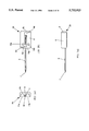
- FIGS. 1a1, 1a2, and 1a3 are top, side and front front elevation views of an embodiment of the biopsy handle instrument of this invention.
- FIGS. 1b1, 1b2, and 1b3 are top, side, front, and elevation views of an embodiment of the needle set or needle cartridge of this invention. These figures depict the needle set in the locked position.
- FIGS. 1c1, 1c2, and 1c3 are top views of the inventive needle set of FIG. 1b1 showing the sequence of actions that define the movement of the independent needle hubs as they function in the handle mechanism.
- FIGS. 1d1, 1d2, and 1d3 are top, side and front elevation views of an embodiment of the biopsy handle instrument of this invention, similar to FIGS. 1a1, 1a2, and 1a3 with the lid that covers the handle mechanism removed.
- FIG. 1e is a side elevation view of the invention with the inventive needle set or needle cartridge positioned under the lid, ready to be placed down inside the handle mechanism of the invention.
- FIGS. 1f1, 1f2, and 1f3 are top, side and front elevation views of the biopsy instrument of this invention with the lid that covers the mechanism removed. These figures depict the handle with the needle set in place.
- FIG. 1g depicts an alternative embodiment of the needle set or needle cartridge with the handle engaging ports repositioned in order to find a different stroke length for the needle set.
- FIG. 1h depicts yet another alternative embodiment of the needle set or needle cartridge with multiple handle engaging ports which are selectable in order to set different biopsy tissue collecting strokes of the needle set.
- FIG. 2a is a cross-sectional view taker through line 2a-2a of FIG. 1f1 and shows the embodiment of the handle of the invention wherein a first driver for moving a first needle of the needle set is in an uncocked position.
- FIG. 2b shows a view similar to FIG. 2a but with the first driver in a cocked position.
- FIG. 2c is a view similar to FIG. 2b but with a thumb knob which was used to cock the mechanism return to its original position.
- FIGS. 3a through 3e show a top view of an embodiment of the invention in different operational steps.
- the instrument 40 (FIG. 3a) is of a spring powered, mechanical design.
- the needle set 20 (FIG. 1b1) is separate and disposable.
- the preferably disposable and preferably plastic hubs 6, 8, of the needle set 20 have been designed to operate as moving parts with the operational mechanism of the handle 1 (FIG. 1a1).
- the hubs 6, 8 of the needle set or needle cartridge 20 act as the bearing surfaces of the moving parts within the handle, thus precluding the need of tight tolerance bearing, bushings or guide rods.
- the hubs 6, 8 act as the carriers for the needles 7, 9 in the handle.
- the needle set 20 is comprised of said interlocking hubs 6, 8.
- the interlocking hubs 6, 8 form a rectangular unit when the two needle hubs are locked together when tabs 30, 31 (FIG. 1c2), fit into slots such as slot 32 (FIG. 1b3), the hubs.
- the hubs 3, 8 are capable of moving axially in relation to each other to allow the sequencing of the individual needles 7, 9 in the handle 1.
- Each hub 6, 8 contains a needle 7, 9.
- One hub 6 holds a stylet 7 that is a solid needle with a notch 12 ground in this distal end that is positioned coaxially inside the cannula 9.
- the 9 cannula is housed in the mating hub 8 which interlocks with the style hub 6.
- the cannula 9 is a hollow needle with a sharpened distal tip.
- the cannula 9 fits over the stylet 7 and when slid forward, towards the distal end of the stylet 7 during the biopsy procedure, cuts and captures the tissue inside the notched area 12 of the distal end of the stylet.
- Stylet hub 6 includes arms 6a and 6b extending therefrom.
- Cannula hub 8 includes arms 8a and 8b extending therefrom.
- Arm 6b is located between arms 8a and 8b while arm 8a is located between arms 6a and 6b.
- Stylet 7 is secured to arm 6b and is disposed inside cannula 9.
- Cannula is secured to arm 8a and projects through a port of arm 6a.
- a pointed tip facilitates the introduction of the needle set 20 into the tissue mass.
- the stylet 7 is positioned to protrude slightly beyond the end of the cannula 9 in the cocked position (FIG. 1c1). In the cocked position, the stylet 7 prevents tissue from entering the cannula 9 as the needle set 20 is introduced into the body.
- the interlocking hubs 6, 8 of the needle set 20 form the above referenced rectangular block when the individual hubs 6, 8 are locked together.
- the needles 7, 9 are aligned axially to allow the manual placement of the needle set 20 in the body separate from the handle. This feature allows the needle set to be used in CAT scanning without the use of a separate "needle spacer” to orient the needles and hold them in the proper alignment for mounting into the handle 1.
- the inventive handle 1 includes a pair of cylindrical guide tubes 13, 14, each contains a spring backed drive block 15, 16 to which the needle set hubs 6, 8 are attached (FIG. 1d1).
- the needle set hubs 6, 8 are attached to the drive blocks 15, 16 by placing them onto protruding pin 17, 18 in the drive block 15, 16 that are perpendicular to the axis of the guide tubes 13, 14. As is evident, there is a guide tube and drive block for each the stylet and cannula as these are actuated separately.
- Each needle hub 6, 8 contains a channel 11a, 11b (FIG. 1b3) that is formed in the body of the hub and that runs parallel to the axis of the needles 7, 9. These channels accept the guide tubes 13, 14 of the handle 1.
- the needle hub channels 11a, 11b move axially along the guide tubes 13, 14 driven by the spring backed drive blocks 15, 16.
- the drive blocks 15, 16 are pushed backwards in the guide tube by means of thumb knobs 3, 4 (FIG. 1a1) that compress main springs 22a, 22b (FIGS. 2a, 2d).
- a locking mechanism 25a, 25b holds the drive blocks 15, 16 and main springs 22a, 22b in a spring compressed state. With both drive blocks 15, 16 pushed back into their locked state, the needle set hub 6, 8 can be positioned into the handle 1 in preparation for the sequencing of the needle set.
- the stylet 17 is positioned inside the cannula 9 and protrudes slightly out of the distal end of said cannula 9, thus preventing tissue from entering the cannula 9 during insertion into the body.
- Each needle hub 6, 8 has a through hole 10a, 10b (FIG. 1b1) that accepts the protruding pin 17, 18 of the drive block 15, 16.
- Needle sets 20 can be provided with the location of these holes 10a, 10b, in a variety of distances from the distal end of the needle set (FIGS. 1b1, 1g, 1h). The position of the holes 10a, 10b and the distance from the distal end 10g of the needle set determines the distance the needle set will move forward in the body. This distance between the holes 10a, 10b in the hub 6, 8 and the distal end 10f of the needle hub determines the length of needle actuation, not the mechanism of the handle design. Thus, the position of the holes 10a, 10b in FIG.
- FIG. 1h ensure that the stroke of the stylet and cannula are shorter and thus the tissue sample collected is shorter.
- FIG. 1h has six holes (three hole sets) 10a, 10b, 10c, 10d, 10e, and 10f. Selection of any set of holes changes the stroke length of the needle set 20.
- the handle contains two thumb knobs 3, 4 (FIG. 1b1). Each knob 3, 4 independently operates the drive block 15, 16 and main spring 22a, 22b of the stylet and cannula needle hubs 6, 8.
- the handle 1 To use the invention in performing a biopsy procedure, the handle 1 must be prepared first.
- the thumb knob 3 for the cannula 9 is actuated first, placing the drive block 15 (for the cannula hub 8) in the locked position with the drive block 15 holding the main spring 22a in a compressed state.
- the thumb knob 4 of the stylet 7 is then actuated, placing the drive block 16 (for the stylet hole 6) in the locked position with the drive block 16 holding the main spring 22b in a compressed state.
- An internal spring 23a, 23b (FIGS. 2a, 2d) in each thumb knob 3, 4 returns it to a neutral state after the drive block 15, 16 has been pushed back into locked positions.
- the locked needle set 20 can be positioned into the handle 1.
- an outer lid 2 (FIG. 1e) that covers the moving parts of the handle 1 is raised and the locked needle hubs 6, 8 are positioned over the protruding pins 17, 18 of the drive blocks 15, 16.
- the needles 7, 9 fit down between the two thumb knobs 3, 4 and the lid 2 can then be closed.
- the trigger 5 is moved and the first needle sequence is activated.
- the stylet 7 moves forward urged by the compressed spring 22b driving the drive block 16 forward.
- the protruding pin 18 from the drive block 16 which is located in the hole 10b of the stylet hub 6 moves the stylet hub 6 forward until it strikes the back of thumb knob 4, thus stopping its forward motion.
- an arm 6a (FIG. 1b1) of the stylet hub 6 strikes an actuator bar 21a (FIG. 3b) of cannula trigger 21 (FIG. 2a) in the mechanism of the handle 1.
- the arm 6c of the stylet hub 6 moves the actuator bar 21a in the mechanism of the handle 1 forward, thus releasing the cannula drive block 15 from its locked position.
- the actuator bar 21a is moved forward, the second needle sequence is activated.
- the cannula 3 moves forward urged by the compressed spring 22a, driving the drive block 15 forward.
- the protruding pin 17 from the drive block 15 which is located in the hole 10a of the cannula hub 8 moves the cannula hub 8 forward until it strikes the back stylet hub arm 6a which is against thumb knob 3, thus stopping its forward motion.
- the stylet 7 is pushed into tissue, the tissue is pierced and relaxes into the notched cut out.
- the cannula thumb knob 3 is activated and the drive block 15 and cannula 9 are retracted, the cannula 9 is moved backwards over the stylet 7, thus exposing the tissue core in the notched stylet 7 (FIG. 3d). This action allows the removal of the tissue core from the stylet 7 so it can be examined. Cocking the thumb knob 4 for the stylet 7 resets the instrument 40 for an additional biopsy attempt (FIG. 3e).
- FIG. 1a1, 1a2, and 1a3 depict the major components of the inventive biopsy instrument 40.
- the main housing or handle 1 of the instrument has a cover lid 2 that shields the inner mechanism.
- the cannula and stylet thumb knobs 3, 4, respectively, are depicted.
- the trigger 5 (which is connected to stylet trigger extension 19), which when actuated by sliding it along the length of handle 1, begins the sequence of needle motions associated with the mechanism of the inventive device is also depicted.
- FIGS. 1b1, 1b2, and 1b3 depict the inventive needle set 20.
- Item 6 is the stylet hub 6 and is attached to the stylet needle 7.
- the cannula hub 8 is attached to cannula needle 9.
- Each needle hub 6, 8 has a mounting hole 10a, 10b. Holes 10a, 10b are used to attach and drive the needles independently inside the handle 1 of the inventive biopsy device.
- the shape of the needle hubs 6, 8 create two parallel grooves 11a, 11b, that guide the motion of the needle hubs 6, 8 in the handle 1.
- FIGS. 1c1, 1c2, and 1c3 depict the inventive needle set 20 showing the sequence of actions that define the movement of the independent needle hubs 6, 8 as they function.
- the stylet needle hub 6 moves forward, the stylet needle 7 is moved forward in relation to the cannula needle 9.
- This forward motion of needle hub 6 and stylet 7 exposes the notched detail 12 as it protrudes past the end of cannula 9.
- the cannula hub 8 then moves forward urging the cannula needle forward coaxially over stylet 7, covering and capturing any tissue that lies in the notch 12, the needle 7.
- FIGS. 1d1, 1d2, and 1d3 depict the handle 1 of the biopsy instrument of this invention, with the lid 2 that covers the mechanism removed.
- Inside housing 1 are two parallel tubes 13, 14.
- Inside tubes 13, 14 are two drive blocks 15, 16. Attached to these two drive blocks 15, 16 are two drive pins 17, 18. Pins 17, 18 are the devices that attach and drive the needle hubs 6, 8.
- Stylet trigger extension 19 is an extension of trigger 5.
- Trigger extension 19 is the device that releases block 16 from its spring compressing state, thus driving the first needle hub 6 forward.
- Cannula trigger 21 is activated by the stylet hub arms 6a, thus releasing the cannula hub 8 from the spring compressed position.
- FIG. 1e is a side view of the invention with the inventive needle set 20 positioned under the lid 2, ready to be placed down inside the handle 1 of the invention.
- FIGS. 1f1, 1f2, and 1f3 depict the inventive needle set 20 positioned inside the handle 1 of the inventive biopsy device.
- FIGS. 2a, 2b and 2c depict cross-section views of the embodiment of the handle 1 inventive biopsy instrument.
- FIG. 2a a cross-section view of the inventive biopsy device is depicted cut on the axial centerline of the cannula drive tube 13.
- FIG. 2a shows the major components of the mechanism.
- the cannula thumb knob 3 contains a push rod 24a. Push rod 24a rests against the drive block 15 and is biased forward by the thumb knob return spring 23a. Inside the drive tube 13 are the drive block 15 and the main spring 22a.
- the drive block 15 contains the drive pin 17 and the catch block 25a.
- the catch block 25a is the device that holds the drive block 15 in position with the main spring 22a in compression.
- FIG. 2a also depicts the cannula trigger 21 and extension 21a which slides axially along the drive tube 13.
- a cutout 26a of the cannula trigger 21 is the actuating device for releasing the drive block 15 from its spring compressed position by releasing the catch block 25a from its locked position.
- FIG. 2b is a cross-section view of the inventive biopsy device handle 1 depicted cut on the axial centerline of the cannula drive tube 13.
- FIG. 2b shows the inventive biopsy device being in a cocked position.
- the cannula thumb knob 3 is depressed towards the distal end of the handle 1.
- the push rod 24a pushes the drive block 15 back, compressing the main spring 22a.
- As the cannula thumb knob 3 is depressed it also moves the cannula trigger 21 back.
- the drive block 15 moves backwards, it reaches a point where the catch block 25a is urged down into the drive tube slot 28a by the compressed catch spring 29a.
- FIG. 2c a cross-section view of the inventive biopsy device is depicted cut on the axial centerline of the cannula drive tube 13.
- FIG. 2c depicts the inventive biopsy device in the "ready to fire” position.
- the drive block 15 is locked in position by the catch block 25a, holding the main spring 22a in compression.
- the thumb knob return spring 22a has biased the cannula thumb knob 3 forward out of the way so that when the catch block 25a is released by the forward motion of the cannula trigger 21, the drive block 15 may move forward unimpeded.
- FIG. 2d a cross-section view of the inventive biopsy device is depicted cut on the axial centerline of the stylet drive tube 14.
- FIG. 2d shows the major components of the mechanism.
- the stylet thumb knob 4 contains a push rod 24b.
- Push rod 24b rests against the drive block 16 and is biased forward by the thumb knot return spring 23b.
- Inside the drive tube 14 are the drive block 16 and the main spring 22b.
- the drive block 16 contains the drive pin 18 and the catch block 25b.
- the catch block 25b is the device that holds the drive block 16 in position with the main spring 22b in compression.
- FIG. 2d also depicts the stylet trigger extension 19 which slides axially below the drive tube 14. Cutout 26b of the stylet trigger extension 19 is the actuating device for releasing the drive block 16 from its spring compressed state by releasing the catch block 25b from its locked position.
- FIG. 2e a cross-section view of the inventive biopsy device is depicted cut on the axial centerline of the stylet drive tube 14.
- FIG. 2e shows the inventive biopsy device being cocked.
- the stylet thumb knob 4 is depressed towards the distal end of the handle 1.
- the push rod 24b pushes the drive block 16 back, compressing the main spring 22b.
- the drive block 16 moves backwards, and reaches a point where the catch block 25b is urged down into the drive tube slot 28b by the compressed catch spring 29b.
- the catch block 25b is urged down through the drive tube slot 28b, the catch block 25b moves into the cutout 26b of the stylet trigger extension 19.
- the drive block 16 is held in place under the compression of the main spring 22b by the catch block 25b resting in the drive tube slot 28b.
- FIG. 2f a cross-section view of the inventive biopsy device is depicted cut on the axial centerline of the stylet drive tube 14.
- FIG. 2f depicts the inventive biopsy device in the "ready to fire” position.
- the drive block 16 is locked in position by the catch block 25b, holding the main spring 22b in compression.
- the thumb knob return spring 22b has biased the stylet thumb knob 4 forward out of the way so that when the catch block 25b is released by the forward motion of the stylet trigger 5 and the stylet trigger extension 19, the drive block 16 may move forward unimpeded.
- FIG. 3a is a top elevation view of the biopsy instrument 40 of this invention with the lid 2 that covers the mechanism removed.
- FIG. 3a depicts the device with needle set 20 in place.
- FIG. 3a depicts the handle 1 with the cannula needle hub 8 in the cocked position and the stylet needle hub 6 in the cocked position.
- FIG. 3a depicts that the forward motion of the trigger 5 releases the stylet hub 6 from its spring compressed position.
- FIG. 3b is a top elevation view of the biopsy instrument 40 of this invention with the lid 2 that covers the handle 1 removed.
- FIG. 3b depicts the handle 1 with the needle set 20 in place.
- FIG. 3b depicts the device with the cannula needle hub 8 in the cocked position and the stylet needle hub 6 moving forward.
- FIG. 3b depicts the forward motion of the stylet hub 6 striking the cannula trigger extension 21a, and pushing extension 21a forward, thus releasing the cannula hub 8 from the spring compressed position.
- FIG. 3c is a top elevation view of the biopsy instrument 40 of this invention with the lid that covers the mechanism removed.
- FIG. 3c depicts the handle 1 with the needle set 20 in place.
- FIG. 3c depicts the handle 1 with the styles needle hub 6 in the fired position and the cannula needle hub 8 moving forward.
- FIG. 3c depicts that the forward motion of the cannula hub 8, stopped as it meets the stylet hub 6, thus finishing the cycle of needle actions.
- FIGS. 3d and 3e the sequence of cocking the inventive mechanism is depicted.
- the cannula thumb knob 3 is depressed towards the rear of the handle 1. This action pushes the cannula hub 8 back to its locked position.
- the stylet thumb knob 4 is depressed towards the rear of the device. This action pushes the stylet hub 6 back to its locked position.
- the present invention provides for an inventive handle and needle set which simplifies the biopsy procedure and which is easy to use and make.
- the inventive needle set incorporates some of the operational features of the handle, thereby reducing or eliminating design needs and tolerances of the handle.
- the disposable needle set thus affords a simpler design for the handle, allowing the handle to be inexpensive to make and more compact.
Abstract
Description
Claims (31)
Priority Applications (4)
| Application Number | Priority Date | Filing Date | Title |
|---|---|---|---|
| US08/669,039 US5752923A (en) | 1996-06-24 | 1996-06-24 | Biopsy instrument with handle and needle set |
| EP97916055A EP0910283B1 (en) | 1996-06-24 | 1997-03-18 | Biopsy instrument with handle and needle set |
| PCT/US1997/004305 WO1997049339A1 (en) | 1996-06-24 | 1997-03-18 | Biopsy instrument with handle and needle set |
| JP50292198A JP3880628B2 (en) | 1996-06-24 | 1997-03-18 | Biopsy instrument with handle and needle set |
Applications Claiming Priority (1)
| Application Number | Priority Date | Filing Date | Title |
|---|---|---|---|
| US08/669,039 US5752923A (en) | 1996-06-24 | 1996-06-24 | Biopsy instrument with handle and needle set |
Publications (1)
| Publication Number | Publication Date |
|---|---|
| US5752923A true US5752923A (en) | 1998-05-19 |
Family
ID=24684772
Family Applications (1)
| Application Number | Title | Priority Date | Filing Date |
|---|---|---|---|
| US08/669,039 Expired - Lifetime US5752923A (en) | 1996-06-24 | 1996-06-24 | Biopsy instrument with handle and needle set |
Country Status (4)
| Country | Link |
|---|---|
| US (1) | US5752923A (en) |
| EP (1) | EP0910283B1 (en) |
| JP (1) | JP3880628B2 (en) |
| WO (1) | WO1997049339A1 (en) |
Cited By (116)
| Publication number | Priority date | Publication date | Assignee | Title |
|---|---|---|---|---|
| US6019733A (en) | 1997-09-19 | 2000-02-01 | United States Surgical Corporation | Biopsy apparatus and method |
| US6050955A (en) | 1997-09-19 | 2000-04-18 | United States Surgical Corporation | Biopsy apparatus and method |
| WO2000030546A1 (en) * | 1998-11-25 | 2000-06-02 | United States Surgical Corporation | Biopsy system |
| DE19848513A1 (en) * | 1998-10-21 | 2000-08-10 | Daum Gmbh | Semi-automatic biopsy instrument with needle uses clamped grip in slide to operate spring so slide first latches and is then freed to initiate biopsy. |
| US6142955A (en) | 1997-09-19 | 2000-11-07 | United States Surgical Corporation | Biopsy apparatus and method |
| US6193673B1 (en) | 1998-02-20 | 2001-02-27 | United States Surgical Corporation | Biopsy instrument driver apparatus |
| US6221030B1 (en) * | 1998-12-04 | 2001-04-24 | Gallini S.R.L. | Automatic biopsy device |
| US6221029B1 (en) | 1999-05-13 | 2001-04-24 | Stryker Corporation | Universal biopsy system |
| US6554778B1 (en) | 2001-01-26 | 2003-04-29 | Manan Medical Products, Inc. | Biopsy device with removable handle |
| US6712773B1 (en) | 2000-09-11 | 2004-03-30 | Tyco Healthcare Group Lp | Biopsy system |
| US20040077973A1 (en) * | 2002-10-22 | 2004-04-22 | Groenke Gregory C. | Biopsy device handle assembly |
| US20040153002A1 (en) * | 2003-01-31 | 2004-08-05 | Schramm John B. | Integrated biopsy needle assembly |
| US20040158172A1 (en) * | 2003-02-11 | 2004-08-12 | Promex/ Us Biopsy, Llc | Single-handed biopsy system |
| US20040158202A1 (en) * | 2003-02-12 | 2004-08-12 | Soren Jensen | Cover |
| US20040199123A1 (en) * | 2003-04-01 | 2004-10-07 | Nielsen Jens Egebjerg | Infusion device and an adhesive sheet material and a release liner |
| US20040238392A1 (en) * | 2003-06-02 | 2004-12-02 | Peterson Rod T. | Intraocular lens and cartridge packaging with lens-loading function |
| US20050090784A1 (en) * | 1998-07-14 | 2005-04-28 | Maersk Medical A/S | Medical puncturing device |
| US20050165404A1 (en) * | 2002-05-31 | 2005-07-28 | Miller Larry J. | Manual interosseous device |
| US20060030785A1 (en) * | 2004-05-11 | 2006-02-09 | Inrad, Inc. | Core biopsy device |
| US20060036212A1 (en) * | 2002-05-31 | 2006-02-16 | Miller Larry J | Apparatus and method to access bone marrow |
| US20060173377A1 (en) * | 2005-01-31 | 2006-08-03 | Mccullough Adam B | Quick cycle biopsy system |
| US20060186256A1 (en) * | 2002-09-02 | 2006-08-24 | Mogensen Lasse W | Apparatus for and a method of adjusting the length of an infusion tube |
| US20060229528A1 (en) * | 2003-03-29 | 2006-10-12 | C. R. Brad, Inc. | Coaxial cannula provided with a sealing element |
| US20070049945A1 (en) * | 2002-05-31 | 2007-03-01 | Miller Larry J | Apparatus and methods to install, support and/or monitor performance of intraosseous devices |
| US20070149894A1 (en) * | 2002-03-19 | 2007-06-28 | C.R. Bard, Inc. | Biopsy device for removing tissue specimens using a vacuum |
| US20070149893A1 (en) * | 2002-03-19 | 2007-06-28 | C.R. Bard, Inc. | Biopsy device and biopsy needle module that can be inserted into the biopsy device |
| US20070219461A1 (en) * | 2005-07-11 | 2007-09-20 | Tyco Healthcare Group Lp | Needle assembly including obturator with safety reset |
| US20080071193A1 (en) * | 2004-07-09 | 2008-03-20 | Claus Reuber | Length Detection System for Biopsy Device |
| US20080140014A1 (en) * | 2006-10-30 | 2008-06-12 | Miller Larry J | Apparatus And Methods To Communicate Fluids And/Or Support Intraosseous Devices |
| US20080306406A1 (en) * | 2005-08-10 | 2008-12-11 | C.R. Bard Inc. | Single-Insertion, Multiple Sampling Biopsy Device With Linear Drive |
| US20080319341A1 (en) * | 2005-08-10 | 2008-12-25 | C.R. Bard Inc. | Single-Insertion, Multiple Sample Biopsy Device with Integrated Markers |
| US20090012423A1 (en) * | 2004-05-11 | 2009-01-08 | Inrad, Inc. | Core Biopsy Device |
| US20090118639A1 (en) * | 2007-11-01 | 2009-05-07 | Tyco Healthcare Group Lp | Active Stylet Safety Shield |
| US7648494B2 (en) | 2004-03-26 | 2010-01-19 | Unomedical A/S | Infusion set and injector device for infusion set |
| US7654735B2 (en) | 2005-11-03 | 2010-02-02 | Covidien Ag | Electronic thermometer |
| US20100030108A1 (en) * | 2006-10-24 | 2010-02-04 | C.R. Bard, Inc. | Large sample low aspect ratio biopsy needle |
| US7731692B2 (en) | 2005-07-11 | 2010-06-08 | Covidien Ag | Device for shielding a sharp tip of a cannula and method of using the same |
| US7762961B2 (en) | 2003-03-29 | 2010-07-27 | C. R. Bard, Inc. | Pressure generating unit |
| US7802824B2 (en) | 2002-11-26 | 2010-09-28 | Unomedical A/S | Connecting piece for a tubing |
| US7811260B2 (en) | 2002-05-31 | 2010-10-12 | Vidacare Corporation | Apparatus and method to inject fluids into bone marrow and other target sites |
| US7815642B2 (en) | 2004-01-26 | 2010-10-19 | Vidacare Corporation | Impact-driven intraosseous needle |
| US7850650B2 (en) | 2005-07-11 | 2010-12-14 | Covidien Ag | Needle safety shield with reset |
| US7850620B2 (en) | 2002-05-31 | 2010-12-14 | Vidacare Corporation | Biopsy devices and related methods |
| US7867199B2 (en) | 2004-12-10 | 2011-01-11 | Unomedical A/S | Inserter |
| US7905857B2 (en) | 2005-07-11 | 2011-03-15 | Covidien Ag | Needle assembly including obturator with safety reset |
| US7951089B2 (en) | 2002-05-31 | 2011-05-31 | Vidacare Corporation | Apparatus and methods to harvest bone and bone marrow |
| US7985199B2 (en) | 2005-03-17 | 2011-07-26 | Unomedical A/S | Gateway system |
| US8012126B2 (en) | 2006-10-31 | 2011-09-06 | Unomedical A/S | Infusion set |
| US8062250B2 (en) | 2004-08-10 | 2011-11-22 | Unomedical A/S | Cannula device |
| USD655807S1 (en) | 2005-12-09 | 2012-03-13 | Unomedical A/S | Medical device |
| US8142365B2 (en) | 2002-05-31 | 2012-03-27 | Vidacare Corporation | Apparatus and method for accessing the bone marrow of the sternum |
| US8152771B2 (en) | 2001-09-27 | 2012-04-10 | Unomedical A/S | Injector device for placing a subcutaneous infusion set |
| US8246588B2 (en) | 2007-07-18 | 2012-08-21 | Unomedical A/S | Insertion device with pivoting action |
| US8251917B2 (en) | 2006-08-21 | 2012-08-28 | C. R. Bard, Inc. | Self-contained handheld biopsy needle |
| US8282574B2 (en) | 2005-08-10 | 2012-10-09 | C. R. Bard, Inc. | Single-insertion, multiple sampling biopsy device usable with various transport systems and integrated markers |
| US8303549B2 (en) | 2005-12-23 | 2012-11-06 | Unomedical A/S | Injection device |
| US8419683B2 (en) | 2004-11-12 | 2013-04-16 | Vidacare Corporation | Intraosseous device and methods for accessing bone marrow in the sternum and other target areas |
| US8430824B2 (en) | 2009-10-29 | 2013-04-30 | Bard Peripheral Vascular, Inc. | Biopsy driver assembly having a control circuit for conserving battery power |
| US8430850B2 (en) | 2007-07-03 | 2013-04-30 | Unomedical A/S | Inserter having bistable equilibrium states |
| US8439838B2 (en) | 2006-06-07 | 2013-05-14 | Unomedical A/S | Inserter for transcutaneous sensor |
| US8454532B2 (en) | 2007-12-27 | 2013-06-04 | Devicor Medical Products, Inc. | Clutch and valving system for tetherless biopsy device |
| US8485989B2 (en) | 2009-09-01 | 2013-07-16 | Bard Peripheral Vascular, Inc. | Biopsy apparatus having a tissue sample retrieval mechanism |
| US8485987B2 (en) | 2006-10-06 | 2013-07-16 | Bard Peripheral Vascular, Inc. | Tissue handling system with reduced operator exposure |
| US8486003B2 (en) | 2007-07-10 | 2013-07-16 | Unomedical A/S | Inserter having two springs |
| US8562567B2 (en) | 2009-07-30 | 2013-10-22 | Unomedical A/S | Inserter device with horizontal moving part |
| US8597205B2 (en) | 2007-12-20 | 2013-12-03 | C. R. Bard, Inc. | Biopsy device |
| US8597206B2 (en) | 2009-10-12 | 2013-12-03 | Bard Peripheral Vascular, Inc. | Biopsy probe assembly having a mechanism to prevent misalignment of components prior to installation |
| US8656929B2 (en) | 2002-05-31 | 2014-02-25 | Vidacare Corporation | Medical procedures trays and related methods |
| US8668698B2 (en) | 2002-05-31 | 2014-03-11 | Vidacare Corporation | Assembly for coupling powered driver with intraosseous device |
| US8690793B2 (en) | 2009-03-16 | 2014-04-08 | C. R. Bard, Inc. | Biopsy device having rotational cutting |
| US8690791B2 (en) | 2002-05-31 | 2014-04-08 | Vidacare Corporation | Apparatus and method to access the bone marrow |
| US8708930B2 (en) | 2009-04-15 | 2014-04-29 | Bard Peripheral Vascular, Inc. | Biopsy apparatus having integrated fluid management |
| US8790311B2 (en) | 2006-06-09 | 2014-07-29 | Unomedical A/S | Mounting pad |
| US8834417B2 (en) | 2005-06-06 | 2014-09-16 | Covidien Ag | Needle assembly with removable depth stop |
| US8845548B2 (en) | 2009-06-12 | 2014-09-30 | Devicor Medical Products, Inc. | Cutter drive assembly for biopsy device |
| US8945057B2 (en) | 2006-08-02 | 2015-02-03 | Unomedical A/S | Cannula and delivery device |
| US8944069B2 (en) | 2006-09-12 | 2015-02-03 | Vidacare Corporation | Assemblies for coupling intraosseous (IO) devices to powered drivers |
| US9072543B2 (en) | 2002-05-31 | 2015-07-07 | Vidacare LLC | Vascular access kits and methods |
| US9149260B2 (en) | 2014-02-28 | 2015-10-06 | 3DBiopsy LLC | Biopsy needle assembly |
| US9173641B2 (en) | 2009-08-12 | 2015-11-03 | C. R. Bard, Inc. | Biopsy apparatus having integrated thumbwheel mechanism for manual rotation of biopsy cannula |
| US9186480B2 (en) | 2007-06-20 | 2015-11-17 | Unomedical A/S | Apparatus for making a catheter |
| US9211379B2 (en) | 2006-02-28 | 2015-12-15 | Unomedical A/S | Inserter for infusion part and infusion part provided with needle protector |
| US9254373B2 (en) | 2008-12-22 | 2016-02-09 | Unomedical A/S | Medical device comprising adhesive pad |
| US9314228B2 (en) | 2002-05-31 | 2016-04-19 | Vidacare LLC | Apparatus and method for accessing the bone marrow |
| US9415159B2 (en) | 2010-03-30 | 2016-08-16 | Unomedical A/S | Medical device |
| US9433400B2 (en) | 2004-01-26 | 2016-09-06 | Vidacare LLC | Manual intraosseous device |
| US9440051B2 (en) | 2011-10-27 | 2016-09-13 | Unomedical A/S | Inserter for a multiplicity of subcutaneous parts |
| US9451968B2 (en) | 2002-05-31 | 2016-09-27 | Vidacare LLC | Powered drivers, intraosseous devices and methods to access bone marrow |
| US9504477B2 (en) | 2003-05-30 | 2016-11-29 | Vidacare LLC | Powered driver |
| US9510910B2 (en) | 2006-09-12 | 2016-12-06 | Vidacare LLC | Medical procedures trays and related methods |
| US9533092B2 (en) | 2009-08-07 | 2017-01-03 | Unomedical A/S | Base part for a medication delivery device |
| US9545243B2 (en) | 2002-05-31 | 2017-01-17 | Vidacare LLC | Bone marrow aspiration devices and related methods |
| US9566384B2 (en) | 2008-02-20 | 2017-02-14 | Unomedical A/S | Insertion device with horizontally moving part |
| US9724127B2 (en) | 2010-09-27 | 2017-08-08 | Unomedical A/S | Insertion system and insertion kit |
| US9844362B2 (en) | 2015-01-13 | 2017-12-19 | Covidien Lp | Exchangeable core biopsy needle |
| US9968338B2 (en) | 2012-11-21 | 2018-05-15 | C. R. Bard, Inc. | Core needle biopsy device |
| US10159470B2 (en) | 2014-07-30 | 2018-12-25 | Covidien Lp | Exchangeable core biopsy needle |
| US10182798B2 (en) | 2014-07-30 | 2019-01-22 | Covidien Lp | Exchangeable core biopsy needle |
| US10285673B2 (en) | 2013-03-20 | 2019-05-14 | Bard Peripheral Vascular, Inc. | Biopsy device |
| US10369277B2 (en) | 2005-09-12 | 2019-08-06 | Unomedical A/S | Invisible needle |
| US10456119B2 (en) | 2016-10-10 | 2019-10-29 | 3Dbiopsy, Inc. | Biopsy actuator assembly |
| US10456120B2 (en) | 2013-11-05 | 2019-10-29 | C. R. Bard, Inc. | Biopsy device having integrated vacuum |
| US10463350B2 (en) | 2015-05-01 | 2019-11-05 | C. R. Bard, Inc. | Biopsy device |
| US10898643B2 (en) | 2008-02-13 | 2021-01-26 | Unomedical A/S | Sealing between a cannula part and a fluid path |
| US10973545B2 (en) | 2002-05-31 | 2021-04-13 | Teleflex Life Sciences Limited | Powered drivers, intraosseous devices and methods to access bone marrow |
| US10973532B2 (en) | 2002-05-31 | 2021-04-13 | Teleflex Life Sciences Limited | Powered drivers, intraosseous devices and methods to access bone marrow |
| US11020526B2 (en) | 2010-10-04 | 2021-06-01 | Unomedical A/S | Sprinkler cannula |
| US11110261B2 (en) | 2011-10-19 | 2021-09-07 | Unomedical A/S | Infusion tube system and method for manufacture |
| US11116483B2 (en) | 2017-05-19 | 2021-09-14 | Merit Medical Systems, Inc. | Rotating biopsy needle |
| US11197689B2 (en) | 2011-10-05 | 2021-12-14 | Unomedical A/S | Inserter for simultaneous insertion of multiple transcutaneous parts |
| US11259786B2 (en) * | 2017-01-26 | 2022-03-01 | Flower Medical Co., Ltd. | Cutting biopsy instrument |
| US11298202B2 (en) | 2002-05-31 | 2022-04-12 | Teleflex Life Sciences Limited | Biopsy devices and related methods |
| US11337728B2 (en) | 2002-05-31 | 2022-05-24 | Teleflex Life Sciences Limited | Powered drivers, intraosseous devices and methods to access bone marrow |
| US11583442B2 (en) | 2017-04-09 | 2023-02-21 | Sanoculis Ltd. | Device and method for creating a channel in soft tissue |
| US11793498B2 (en) | 2017-05-19 | 2023-10-24 | Merit Medical Systems, Inc. | Biopsy needle devices and methods of use |
| US11844500B2 (en) | 2017-05-19 | 2023-12-19 | Merit Medical Systems, Inc. | Semi-automatic biopsy needle device and methods of use |
Families Citing this family (3)
| Publication number | Priority date | Publication date | Assignee | Title |
|---|---|---|---|---|
| US6283925B1 (en) * | 1998-05-12 | 2001-09-04 | Medical Device Technologies, Inc. | Biopsy needle handle |
| US6106484A (en) * | 1998-05-12 | 2000-08-22 | Medical Device Technologies, Inc. | Reusable automated biopsy needle handle |
| JP6104732B2 (en) * | 2013-06-21 | 2017-03-29 | 株式会社タスク | Biopsy device and charging device used therefor |
Citations (36)
| Publication number | Priority date | Publication date | Assignee | Title |
|---|---|---|---|---|
| DE10321C (en) * | A. ROBINSON in Chicago (V. St. v. N. A.) | Apparatus for post-fermentation of leaf tobacco using moist heat | ||
| SU175611A1 (en) * | Я. Е. Грингауз, Л. С. Корогодский , М. Г. Кузевич | TOOL FOR PUNKING BIOPSY | ||
| GB709714A (en) * | 1950-11-17 | 1954-06-02 | Eric Oliver Longley | Improvements relating to hypodermic needles |
| GB748451A (en) * | 1952-12-01 | 1956-05-02 | Eric Oliver Longley | Improvements relating to hypodermic needles |
| US3090384A (en) * | 1960-04-15 | 1963-05-21 | Mfg Process Lab Inc | Needle |
| US3732858A (en) * | 1968-09-16 | 1973-05-15 | Surgical Design Corp | Apparatus for removing blood clots, cataracts and other objects from the eye |
| US3788320A (en) * | 1972-02-25 | 1974-01-29 | Kendall & Co | Spinal needle |
| US3844272A (en) * | 1969-02-14 | 1974-10-29 | A Banko | Surgical instruments |
| DD141108A1 (en) * | 1978-12-28 | 1980-04-16 | Heinz Kuhn | EXZISIONSINSTRUMENT |
| US4210146A (en) * | 1978-06-01 | 1980-07-01 | Anton Banko | Surgical instrument with flexible blade |
| US4266555A (en) * | 1979-11-09 | 1981-05-12 | Khosrow Jamshidi | Biopsy needle with stylet and cannula orientation |
| DD159394A1 (en) * | 1981-06-04 | 1983-03-09 | Rudolf Mueller | BIOPSIEKANUELE |
| US4403617A (en) * | 1981-09-08 | 1983-09-13 | Waters Instruments, Inc. | Biopsy needle |
| WO1983003343A1 (en) * | 1982-03-31 | 1983-10-13 | ALLARD, Jan, Hakan | A device for taking tissue samples |
| US4476864A (en) * | 1982-09-29 | 1984-10-16 | Jirayr Tezel | Combined multiple punch and single punch hair transplant cutting device |
| DD221007A1 (en) * | 1983-12-19 | 1985-04-10 | Thueringer Ind Rauenstein Veb | METHOD FOR DIFFERENTIAL TERMINATION MEASUREMENT IN MATERIAL TESTING |
| US4570632A (en) * | 1984-03-16 | 1986-02-18 | Woods Randall L | Cystotome for eye surgery and method of opening lens capsule |
| US4600014A (en) * | 1984-02-10 | 1986-07-15 | Dan Beraha | Transrectal prostate biopsy device and method |
| US4640296A (en) * | 1983-11-12 | 1987-02-03 | Schnepp Pesch Wolfram | Biopsy cannula |
| US4651752A (en) * | 1985-03-08 | 1987-03-24 | Fuerst Erwin J | Biopsy needle |
| US4655226A (en) * | 1983-12-16 | 1987-04-07 | Southland Instruments, Inc. | Disposable biopsy needle unit |
| US4699154A (en) * | 1986-02-19 | 1987-10-13 | Radiplast Ab | Tissue sampling device |
| US4733671A (en) * | 1987-03-17 | 1988-03-29 | Mehl Donald N | Tissue needle |
| US4747414A (en) * | 1985-02-20 | 1988-05-31 | Biologie Et Industrie S.A.R.L. | Instrument for bone marrow puncture |
| US4776346A (en) * | 1984-02-10 | 1988-10-11 | Dan Beraha | Biopsy instrument |
| US4817631A (en) * | 1985-05-23 | 1989-04-04 | Schnepp Pesch Wolfram | Method for removing tissue from a body |
| SU1551362A1 (en) * | 1987-01-08 | 1990-03-23 | Институт металлофизики АН УССР | Device for paracentetic biopsy |
| US4924878A (en) * | 1988-11-07 | 1990-05-15 | Nottke James E | Actuating mechanism for biopsy needle |
| US4958625A (en) * | 1989-07-18 | 1990-09-25 | Boston Scientific Corporation | Biopsy needle instrument |
| DD287650A5 (en) * | 1989-09-11 | 1991-03-07 | Martin-Luther-Universitaet Halle Wittenberg,De | BIOPSIEKANUELE |
| US5025797A (en) * | 1989-03-29 | 1991-06-25 | Baran Gregory W | Automated biopsy instrument |
| US5064411A (en) * | 1988-11-04 | 1991-11-12 | Gordon Iii Kilbourn | Protective medical device |
| USRE34056E (en) * | 1989-07-31 | 1992-09-08 | C.R. Bard, Inc. | Tissue sampling device |
| US5220926A (en) * | 1992-07-13 | 1993-06-22 | Jones George T | Finger mounted core biopsy guide |
| DE9414728U1 (en) * | 1993-09-09 | 1994-12-08 | Heske Norbert | Biopsy needle |
| DE9414727U1 (en) * | 1993-09-09 | 1994-12-08 | Heske Norbert | Biopsy system |
Family Cites Families (5)
| Publication number | Priority date | Publication date | Assignee | Title |
|---|---|---|---|---|
| US4243048A (en) | 1976-09-21 | 1981-01-06 | Jim Zegeer | Biopsy device |
| US4702260A (en) | 1985-04-16 | 1987-10-27 | Ko Pen Wang | Flexible bronchoscopic needle assembly |
| US4702261A (en) * | 1985-07-03 | 1987-10-27 | Sherwood Medical Company | Biopsy device and method |
| US5316013A (en) * | 1991-08-26 | 1994-05-31 | Hart Enterprises, Inc. | Oriented biopsy needle assembly |
| US5449001A (en) | 1994-04-14 | 1995-09-12 | Terwilliger; Richard A. | Biopsy needle |
-
1996
- 1996-06-24 US US08/669,039 patent/US5752923A/en not_active Expired - Lifetime
-
1997
- 1997-03-18 EP EP97916055A patent/EP0910283B1/en not_active Expired - Lifetime
- 1997-03-18 WO PCT/US1997/004305 patent/WO1997049339A1/en active Application Filing
- 1997-03-18 JP JP50292198A patent/JP3880628B2/en not_active Expired - Lifetime
Patent Citations (36)
| Publication number | Priority date | Publication date | Assignee | Title |
|---|---|---|---|---|
| SU175611A1 (en) * | Я. Е. Грингауз, Л. С. Корогодский , М. Г. Кузевич | TOOL FOR PUNKING BIOPSY | ||
| DE10321C (en) * | A. ROBINSON in Chicago (V. St. v. N. A.) | Apparatus for post-fermentation of leaf tobacco using moist heat | ||
| GB709714A (en) * | 1950-11-17 | 1954-06-02 | Eric Oliver Longley | Improvements relating to hypodermic needles |
| GB748451A (en) * | 1952-12-01 | 1956-05-02 | Eric Oliver Longley | Improvements relating to hypodermic needles |
| US3090384A (en) * | 1960-04-15 | 1963-05-21 | Mfg Process Lab Inc | Needle |
| US3732858A (en) * | 1968-09-16 | 1973-05-15 | Surgical Design Corp | Apparatus for removing blood clots, cataracts and other objects from the eye |
| US3844272A (en) * | 1969-02-14 | 1974-10-29 | A Banko | Surgical instruments |
| US3788320A (en) * | 1972-02-25 | 1974-01-29 | Kendall & Co | Spinal needle |
| US4210146A (en) * | 1978-06-01 | 1980-07-01 | Anton Banko | Surgical instrument with flexible blade |
| DD141108A1 (en) * | 1978-12-28 | 1980-04-16 | Heinz Kuhn | EXZISIONSINSTRUMENT |
| US4266555A (en) * | 1979-11-09 | 1981-05-12 | Khosrow Jamshidi | Biopsy needle with stylet and cannula orientation |
| DD159394A1 (en) * | 1981-06-04 | 1983-03-09 | Rudolf Mueller | BIOPSIEKANUELE |
| US4403617A (en) * | 1981-09-08 | 1983-09-13 | Waters Instruments, Inc. | Biopsy needle |
| WO1983003343A1 (en) * | 1982-03-31 | 1983-10-13 | ALLARD, Jan, Hakan | A device for taking tissue samples |
| US4476864A (en) * | 1982-09-29 | 1984-10-16 | Jirayr Tezel | Combined multiple punch and single punch hair transplant cutting device |
| US4640296A (en) * | 1983-11-12 | 1987-02-03 | Schnepp Pesch Wolfram | Biopsy cannula |
| US4655226A (en) * | 1983-12-16 | 1987-04-07 | Southland Instruments, Inc. | Disposable biopsy needle unit |
| DD221007A1 (en) * | 1983-12-19 | 1985-04-10 | Thueringer Ind Rauenstein Veb | METHOD FOR DIFFERENTIAL TERMINATION MEASUREMENT IN MATERIAL TESTING |
| US4600014A (en) * | 1984-02-10 | 1986-07-15 | Dan Beraha | Transrectal prostate biopsy device and method |
| US4776346A (en) * | 1984-02-10 | 1988-10-11 | Dan Beraha | Biopsy instrument |
| US4570632A (en) * | 1984-03-16 | 1986-02-18 | Woods Randall L | Cystotome for eye surgery and method of opening lens capsule |
| US4747414A (en) * | 1985-02-20 | 1988-05-31 | Biologie Et Industrie S.A.R.L. | Instrument for bone marrow puncture |
| US4651752A (en) * | 1985-03-08 | 1987-03-24 | Fuerst Erwin J | Biopsy needle |
| US4817631A (en) * | 1985-05-23 | 1989-04-04 | Schnepp Pesch Wolfram | Method for removing tissue from a body |
| US4699154A (en) * | 1986-02-19 | 1987-10-13 | Radiplast Ab | Tissue sampling device |
| SU1551362A1 (en) * | 1987-01-08 | 1990-03-23 | Институт металлофизики АН УССР | Device for paracentetic biopsy |
| US4733671A (en) * | 1987-03-17 | 1988-03-29 | Mehl Donald N | Tissue needle |
| US5064411A (en) * | 1988-11-04 | 1991-11-12 | Gordon Iii Kilbourn | Protective medical device |
| US4924878A (en) * | 1988-11-07 | 1990-05-15 | Nottke James E | Actuating mechanism for biopsy needle |
| US5025797A (en) * | 1989-03-29 | 1991-06-25 | Baran Gregory W | Automated biopsy instrument |
| US4958625A (en) * | 1989-07-18 | 1990-09-25 | Boston Scientific Corporation | Biopsy needle instrument |
| USRE34056E (en) * | 1989-07-31 | 1992-09-08 | C.R. Bard, Inc. | Tissue sampling device |
| DD287650A5 (en) * | 1989-09-11 | 1991-03-07 | Martin-Luther-Universitaet Halle Wittenberg,De | BIOPSIEKANUELE |
| US5220926A (en) * | 1992-07-13 | 1993-06-22 | Jones George T | Finger mounted core biopsy guide |
| DE9414728U1 (en) * | 1993-09-09 | 1994-12-08 | Heske Norbert | Biopsy needle |
| DE9414727U1 (en) * | 1993-09-09 | 1994-12-08 | Heske Norbert | Biopsy system |
Cited By (281)
| Publication number | Priority date | Publication date | Assignee | Title |
|---|---|---|---|---|
| US6050955A (en) | 1997-09-19 | 2000-04-18 | United States Surgical Corporation | Biopsy apparatus and method |
| US6019733A (en) | 1997-09-19 | 2000-02-01 | United States Surgical Corporation | Biopsy apparatus and method |
| US6142955A (en) | 1997-09-19 | 2000-11-07 | United States Surgical Corporation | Biopsy apparatus and method |
| US6488636B2 (en) | 1997-09-19 | 2002-12-03 | United States Surgical Corporation | Biopsy apparatus |
| US6193673B1 (en) | 1998-02-20 | 2001-02-27 | United States Surgical Corporation | Biopsy instrument driver apparatus |
| US6554779B2 (en) | 1998-02-20 | 2003-04-29 | United States Surgical Corporation | Biopsy instrument driver apparatus |
| US20050090784A1 (en) * | 1998-07-14 | 2005-04-28 | Maersk Medical A/S | Medical puncturing device |
| DE19848513A1 (en) * | 1998-10-21 | 2000-08-10 | Daum Gmbh | Semi-automatic biopsy instrument with needle uses clamped grip in slide to operate spring so slide first latches and is then freed to initiate biopsy. |
| US6436054B1 (en) | 1998-11-25 | 2002-08-20 | United States Surgical Corporation | Biopsy system |
| AU760879B2 (en) * | 1998-11-25 | 2003-05-22 | United States Surgical Corporation | Biopsy system |
| WO2000030546A1 (en) * | 1998-11-25 | 2000-06-02 | United States Surgical Corporation | Biopsy system |
| US6221030B1 (en) * | 1998-12-04 | 2001-04-24 | Gallini S.R.L. | Automatic biopsy device |
| US6221029B1 (en) | 1999-05-13 | 2001-04-24 | Stryker Corporation | Universal biopsy system |
| US6712773B1 (en) | 2000-09-11 | 2004-03-30 | Tyco Healthcare Group Lp | Biopsy system |
| US8128577B2 (en) | 2000-09-11 | 2012-03-06 | Tyco Healthcare Group Lp | Biopsy system |
| US6554778B1 (en) | 2001-01-26 | 2003-04-29 | Manan Medical Products, Inc. | Biopsy device with removable handle |
| US8152771B2 (en) | 2001-09-27 | 2012-04-10 | Unomedical A/S | Injector device for placing a subcutaneous infusion set |
| US8162892B2 (en) | 2001-09-27 | 2012-04-24 | Unomedical A/S | Injector device for placing a subcutaneous infusion set |
| US8172805B2 (en) | 2001-09-27 | 2012-05-08 | Unomedical A/S | Injector device for placing a subcutaneous infusion set |
| US9421002B2 (en) | 2002-03-19 | 2016-08-23 | C. R. Bard, Inc. | Disposable biopsy unit |
| US8172773B2 (en) | 2002-03-19 | 2012-05-08 | C. R. Bard, Inc. | Biopsy device and biopsy needle module that can be inserted into the biopsy device |
| US9439631B2 (en) | 2002-03-19 | 2016-09-13 | C. R. Bard, Inc. | Biopsy device and insertable biopsy needle module |
| US10271827B2 (en) | 2002-03-19 | 2019-04-30 | C. R. Bard, Inc. | Disposable biopsy unit |
| US20070149894A1 (en) * | 2002-03-19 | 2007-06-28 | C.R. Bard, Inc. | Biopsy device for removing tissue specimens using a vacuum |
| US10335128B2 (en) | 2002-03-19 | 2019-07-02 | C. R. Bard, Inc. | Biopsy device and insertable biopsy needle module |
| US9072502B2 (en) | 2002-03-19 | 2015-07-07 | C. R. Bard, Inc. | Disposable biopsy unit |
| US8109885B2 (en) | 2002-03-19 | 2012-02-07 | C. R. Bard, Inc. | Biopsy device for removing tissue specimens using a vacuum |
| US8052614B2 (en) | 2002-03-19 | 2011-11-08 | C. R. Bard, Inc. | Biopsy device having a vacuum pump |
| US8016772B2 (en) | 2002-03-19 | 2011-09-13 | C. R. Bard, Inc. | Biopsy device for removing tissue specimens using a vacuum |
| US11382608B2 (en) | 2002-03-19 | 2022-07-12 | C. R. Bard, Inc. | Disposable biopsy unit |
| US8002713B2 (en) | 2002-03-19 | 2011-08-23 | C. R. Bard, Inc. | Biopsy device and insertable biopsy needle module |
| US8951209B2 (en) | 2002-03-19 | 2015-02-10 | C. R. Bard, Inc. | Biopsy device and insertable biopsy needle module |
| US20070149893A1 (en) * | 2002-03-19 | 2007-06-28 | C.R. Bard, Inc. | Biopsy device and biopsy needle module that can be inserted into the biopsy device |
| US7951089B2 (en) | 2002-05-31 | 2011-05-31 | Vidacare Corporation | Apparatus and methods to harvest bone and bone marrow |
| US7811260B2 (en) | 2002-05-31 | 2010-10-12 | Vidacare Corporation | Apparatus and method to inject fluids into bone marrow and other target sites |
| US8876826B2 (en) | 2002-05-31 | 2014-11-04 | Vidacare Corporation | Apparatus and method to access bone marrow |
| US11337728B2 (en) | 2002-05-31 | 2022-05-24 | Teleflex Life Sciences Limited | Powered drivers, intraosseous devices and methods to access bone marrow |
| US10245010B2 (en) | 2002-05-31 | 2019-04-02 | Teleflex Medical Devices S.A.R.L | Assembly for coupling powered driver with intraosseous device |
| US20070049945A1 (en) * | 2002-05-31 | 2007-03-01 | Miller Larry J | Apparatus and methods to install, support and/or monitor performance of intraosseous devices |
| US8992535B2 (en) | 2002-05-31 | 2015-03-31 | Vidacare LLC | Apparatus and method to provide emergency access to bone marrow |
| US8715287B2 (en) | 2002-05-31 | 2014-05-06 | Vidacare Corporation | Apparatus and method to provide emergency access to bone marrow |
| US11324521B2 (en) | 2002-05-31 | 2022-05-10 | Teleflex Life Sciences Limited | Apparatus and method to access bone marrow |
| US20080015467A1 (en) * | 2002-05-31 | 2008-01-17 | Miller Larry J | Apparatus and Method to Access the Bone Marrow for Oncology and Stem Cell Applications |
| US9072543B2 (en) | 2002-05-31 | 2015-07-07 | Vidacare LLC | Vascular access kits and methods |
| US11298202B2 (en) | 2002-05-31 | 2022-04-12 | Teleflex Life Sciences Limited | Biopsy devices and related methods |
| US11291472B2 (en) | 2002-05-31 | 2022-04-05 | Teleflex Life Sciences Limited | Powered drivers, intraosseous devices and methods to access bone marrow |
| US11266441B2 (en) | 2002-05-31 | 2022-03-08 | Teleflex Life Sciences Limited | Penetrator assembly for accessing bone marrow |
| US9078637B2 (en) | 2002-05-31 | 2015-07-14 | Vidacare LLC | Apparatus and methods to harvest bone and bone marrow |
| US11234683B2 (en) | 2002-05-31 | 2022-02-01 | Teleflex Life Sciences Limited | Assembly for coupling powered driver with intraosseous device |
| US11103282B1 (en) | 2002-05-31 | 2021-08-31 | Teleflex Life Sciences Limited | Powered drivers, intraosseous devices and methods to access bone marrow |
| US11103281B2 (en) | 2002-05-31 | 2021-08-31 | Teleflex Life Sciences Limited | Apparatus and methods to install, support and/or monitor performance of intraosseous devices |
| US9295487B2 (en) | 2002-05-31 | 2016-03-29 | Vidacare LLC | Apparatus and method to inject fluids into bone marrow and other target sites |
| US8690791B2 (en) | 2002-05-31 | 2014-04-08 | Vidacare Corporation | Apparatus and method to access the bone marrow |
| US9314270B2 (en) | 2002-05-31 | 2016-04-19 | Vidacare LLC | Apparatus and method to access bone marrow |
| US10166332B2 (en) | 2002-05-31 | 2019-01-01 | Teleflex Medical Devices S.À R.L. | Apparatus to inject fluids into bone marrow and other target sites |
| US8684978B2 (en) | 2002-05-31 | 2014-04-01 | Vidacare Corporation | Apparatus and method to inject fluids into bone marrow and other target sites |
| US11065382B2 (en) | 2002-05-31 | 2021-07-20 | Teleflex Life Sciences Limited | Apparatus to inject fluids into bone marrow and other target sites |
| US7670328B2 (en) | 2002-05-31 | 2010-03-02 | Vidacare Corporation | Apparatus and method to provide emergency access to bone marrow |
| US8668698B2 (en) | 2002-05-31 | 2014-03-11 | Vidacare Corporation | Assembly for coupling powered driver with intraosseous device |
| US7699850B2 (en) | 2002-05-31 | 2010-04-20 | Vidacare Corporation | Apparatus and method to access bone marrow |
| US10973532B2 (en) | 2002-05-31 | 2021-04-13 | Teleflex Life Sciences Limited | Powered drivers, intraosseous devices and methods to access bone marrow |
| US8656929B2 (en) | 2002-05-31 | 2014-02-25 | Vidacare Corporation | Medical procedures trays and related methods |
| US8641715B2 (en) | 2002-05-31 | 2014-02-04 | Vidacare Corporation | Manual intraosseous device |
| US9314228B2 (en) | 2002-05-31 | 2016-04-19 | Vidacare LLC | Apparatus and method for accessing the bone marrow |
| US20050165404A1 (en) * | 2002-05-31 | 2005-07-28 | Miller Larry J. | Manual interosseous device |
| US9393031B2 (en) | 2002-05-31 | 2016-07-19 | Vidacare LLC | Apparatus and method to provide emergency access to bone marrow |
| US8506568B2 (en) | 2002-05-31 | 2013-08-13 | Vidacare Corporation | Apparatus and method to access bone marrow |
| US10973545B2 (en) | 2002-05-31 | 2021-04-13 | Teleflex Life Sciences Limited | Powered drivers, intraosseous devices and methods to access bone marrow |
| US10893875B2 (en) | 2002-05-31 | 2021-01-19 | Teleflex Life Sciences Limited | Apparatus to access bone marrow |
| US7850620B2 (en) | 2002-05-31 | 2010-12-14 | Vidacare Corporation | Biopsy devices and related methods |
| US9439667B2 (en) | 2002-05-31 | 2016-09-13 | Vidacare LLC | Apparatus and methods to install, support and/or monitor performance of intraosseous devices |
| US10806491B2 (en) | 2002-05-31 | 2020-10-20 | Teleflex Life Sciences Limited | Vascular access kits and methods |
| US8480632B2 (en) | 2002-05-31 | 2013-07-09 | Vidacare Corporation | Cartridge apparatus for injecting fluids into bone |
| US10595896B2 (en) | 2002-05-31 | 2020-03-24 | Teleflex Life Sciences Limited | Apparatus for accessing bone marrow including depth control mechanism |
| US9451968B2 (en) | 2002-05-31 | 2016-09-27 | Vidacare LLC | Powered drivers, intraosseous devices and methods to access bone marrow |
| US10512474B2 (en) | 2002-05-31 | 2019-12-24 | Teleflex Medical Devices S.À R.L. | Powered drivers, intraosseous devices and methods to access bone marrow |
| US9545243B2 (en) | 2002-05-31 | 2017-01-17 | Vidacare LLC | Bone marrow aspiration devices and related methods |
| US10492830B2 (en) | 2002-05-31 | 2019-12-03 | Teleflex Medical Devices S.À R.L. | Penetrator assembly for accessing bone marrow |
| US8142365B2 (en) | 2002-05-31 | 2012-03-27 | Vidacare Corporation | Apparatus and method for accessing the bone marrow of the sternum |
| US10456149B2 (en) | 2002-05-31 | 2019-10-29 | Teleflex Medical Devices S.À R.L. | Apparatus and method to access bone marrow |
| US10413282B2 (en) | 2002-05-31 | 2019-09-17 | Teleflex Medical Devices S.Àr.L. | Apparatus and methods to harvest bone and bone marrow |
| US20060167379A1 (en) * | 2002-05-31 | 2006-07-27 | Miller Larry J | Apparatus and method to access the bone marrow for oncology and stem cell applications |
| US8038664B2 (en) | 2002-05-31 | 2011-10-18 | Vidacare Corporation | Apparatus and method to inject fluids into bone marrow and other target sites |
| US20060167378A1 (en) * | 2002-05-31 | 2006-07-27 | Miller Larry J | Apparatus and method to access the bone marrow for oncology and stem cell applications |
| US9717847B2 (en) | 2002-05-31 | 2017-08-01 | Teleflex Medical Devices S.Àr.L. | Apparatus and method to inject fluids into bone marrow and other target sites |
| US9872703B2 (en) | 2002-05-31 | 2018-01-23 | Teleflex Medical Devices S.Àr.L. | Vascular access kits and methods |
| US8308693B2 (en) | 2002-05-31 | 2012-11-13 | Vidacare Corporation | Bone penetrating needle with angled ports |
| US10016217B2 (en) | 2002-05-31 | 2018-07-10 | Teleflex Medical Devices S.À.R.L. | Apparatus and methods to install, support and/or monitor performance of intraosseous devices |
| US20060052790A1 (en) * | 2002-05-31 | 2006-03-09 | Vidacare Corporation | Apparatus and method to access bone marrow |
| US20060036212A1 (en) * | 2002-05-31 | 2006-02-16 | Miller Larry J | Apparatus and method to access bone marrow |
| US20060186256A1 (en) * | 2002-09-02 | 2006-08-24 | Mogensen Lasse W | Apparatus for and a method of adjusting the length of an infusion tube |
| US7654484B2 (en) | 2002-09-02 | 2010-02-02 | Unomedical A/S | Apparatus for and a method of adjusting the length of an infusion tube |
| US20040077973A1 (en) * | 2002-10-22 | 2004-04-22 | Groenke Gregory C. | Biopsy device handle assembly |
| US20050267383A1 (en) * | 2002-10-22 | 2005-12-01 | Groenke Gregory C | Biopsy device handle assembly |
| US7802824B2 (en) | 2002-11-26 | 2010-09-28 | Unomedical A/S | Connecting piece for a tubing |
| US7063672B2 (en) * | 2003-01-31 | 2006-06-20 | Inter-V Manan | Integrated biopsy needle assembly |
| US20040153002A1 (en) * | 2003-01-31 | 2004-08-05 | Schramm John B. | Integrated biopsy needle assembly |
| US7229419B2 (en) * | 2003-02-11 | 2007-06-12 | Promex/U.S. Biosy Llc | Single-handed biopsy system |
| US20070213635A1 (en) * | 2003-02-11 | 2007-09-13 | Promex/U.S. Biopsy, Llc | Single-handed biopsy system |
| US7585282B2 (en) * | 2003-02-11 | 2009-09-08 | Promex Technologies | Single-handed biopsy system |
| US20040158172A1 (en) * | 2003-02-11 | 2004-08-12 | Promex/ Us Biopsy, Llc | Single-handed biopsy system |
| US20040158202A1 (en) * | 2003-02-12 | 2004-08-12 | Soren Jensen | Cover |
| US7645239B2 (en) | 2003-03-29 | 2010-01-12 | C. R. Bard, Inc. | Coaxial cannula provided with a sealing element |
| US20060229528A1 (en) * | 2003-03-29 | 2006-10-12 | C. R. Brad, Inc. | Coaxial cannula provided with a sealing element |
| US9980706B2 (en) | 2003-03-29 | 2018-05-29 | C. R. Bard, Inc. | Cannula provided with a sealing element for use in a medical procedure |
| US11071529B2 (en) | 2003-03-29 | 2021-07-27 | C.R. Bard, Inc. | Cannula provided with a sealing element for use in a medical procedure |
| US20100076341A1 (en) * | 2003-03-29 | 2010-03-25 | C. R. Bard, Inc. | Cannula provided with a sealing element for use in a medical procedure |
| US7740598B2 (en) | 2003-03-29 | 2010-06-22 | C. R. Bard, Inc. | Coaxial cannula provided with a sealing element |
| US7762961B2 (en) | 2003-03-29 | 2010-07-27 | C. R. Bard, Inc. | Pressure generating unit |
| US8845547B2 (en) | 2003-03-29 | 2014-09-30 | C. R. Bard, Inc. | Cannula provided with a sealing element for use in a medical procedure |
| US7828747B2 (en) | 2003-03-29 | 2010-11-09 | C. R. Bard, Inc. | Pressure generating unit |
| US8162851B2 (en) | 2003-03-29 | 2012-04-24 | C. R. Bard, Inc. | Biopsy needle system having a pressure generating unit |
| US8728004B2 (en) | 2003-03-29 | 2014-05-20 | C.R. Bard, Inc. | Biopsy needle system having a pressure generating unit |
| US20070179403A1 (en) * | 2003-03-29 | 2007-08-02 | C.R. Bard, Inc. | Coaxial cannula provided with a sealing element |
| US9706980B2 (en) | 2003-03-29 | 2017-07-18 | C. R. Bard, Inc. | Cannula provided with a sealing element for use in a medical procedure |
| US20110021946A1 (en) * | 2003-03-29 | 2011-01-27 | C.R. Bard, Inc. | Biopsy needle system having a pressure generating unit |
| US20040199123A1 (en) * | 2003-04-01 | 2004-10-07 | Nielsen Jens Egebjerg | Infusion device and an adhesive sheet material and a release liner |
| US9504477B2 (en) | 2003-05-30 | 2016-11-29 | Vidacare LLC | Powered driver |
| US10052111B2 (en) | 2003-05-30 | 2018-08-21 | Teleflex Medical Devices S.À R.L. | Powered driver |
| US8475527B2 (en) | 2003-06-02 | 2013-07-02 | Abbott Medical Optics Inc. | Intraocular lens and cartridge packaging with lens-loading function |
| US20040238392A1 (en) * | 2003-06-02 | 2004-12-02 | Peterson Rod T. | Intraocular lens and cartridge packaging with lens-loading function |
| US8403941B2 (en) * | 2003-06-02 | 2013-03-26 | Abbott Medical Optics Inc. | Intraocular lens and cartridge packaging with lens-loading function |
| US9907648B2 (en) | 2003-06-02 | 2018-03-06 | Abbott Medical Optics Inc. | Intraocular lens and cartridge packaging with lens-loading function |
| US20070123980A1 (en) * | 2003-06-02 | 2007-05-31 | Advanced Medical Optics, Inc. | Intraocular lens and cartridge packaging with lens-loading function |
| US20070095700A1 (en) * | 2003-06-02 | 2007-05-03 | Advanced Medical Optics, Inc. | Intraocular lens and cartridge packaging with lens-loading function |
| US9433400B2 (en) | 2004-01-26 | 2016-09-06 | Vidacare LLC | Manual intraosseous device |
| US7815642B2 (en) | 2004-01-26 | 2010-10-19 | Vidacare Corporation | Impact-driven intraosseous needle |
| US8870872B2 (en) | 2004-01-26 | 2014-10-28 | Vidacare Corporation | Impact-driven intraosseous needle |
| US8221355B2 (en) | 2004-03-26 | 2012-07-17 | Unomedical A/S | Injection device for infusion set |
| US8287516B2 (en) | 2004-03-26 | 2012-10-16 | Unomedical A/S | Infusion set |
| US7648494B2 (en) | 2004-03-26 | 2010-01-19 | Unomedical A/S | Infusion set and injector device for infusion set |
| US8568334B2 (en) | 2004-05-11 | 2013-10-29 | Inrad, Inc. | Core biopsy device |
| US20090012423A1 (en) * | 2004-05-11 | 2009-01-08 | Inrad, Inc. | Core Biopsy Device |
| US8088081B2 (en) | 2004-05-11 | 2012-01-03 | Inrad, Inc. | Core biopsy device |
| US20060030785A1 (en) * | 2004-05-11 | 2006-02-09 | Inrad, Inc. | Core biopsy device |
| US10166011B2 (en) | 2004-07-09 | 2019-01-01 | Bard Peripheral Vascular, Inc. | Transport system for biopsy device |
| US8992440B2 (en) | 2004-07-09 | 2015-03-31 | Bard Peripheral Vascular, Inc. | Length detection system for biopsy device |
| US9345458B2 (en) | 2004-07-09 | 2016-05-24 | Bard Peripheral Vascular, Inc. | Transport system for biopsy device |
| US9456809B2 (en) | 2004-07-09 | 2016-10-04 | Bard Peripheral Vascular, Inc. | Tissue sample flushing system for biopsy device |
| US20080071193A1 (en) * | 2004-07-09 | 2008-03-20 | Claus Reuber | Length Detection System for Biopsy Device |
| US8864680B2 (en) | 2004-07-09 | 2014-10-21 | Bard Peripheral Vascular, Inc. | Transport system for biopsy device |
| US10499888B2 (en) | 2004-07-09 | 2019-12-10 | Bard Peripheral Vascular, Inc. | Tissue sample flushing system for biopsy device |
| US8157744B2 (en) | 2004-07-09 | 2012-04-17 | Bard Peripheral Vascular, Inc. | Tissue sample flushing system for biopsy device |
| US8052615B2 (en) | 2004-07-09 | 2011-11-08 | Bard Peripheral Vascular, Inc. | Length detection system for biopsy device |
| US9872672B2 (en) | 2004-07-09 | 2018-01-23 | Bard Peripheral Vascular, Inc. | Length detection system for biopsy device |
| US8366636B2 (en) | 2004-07-09 | 2013-02-05 | Bard Peripheral Vascular, Inc. | Firing system for biopsy device |
| US8926527B2 (en) | 2004-07-09 | 2015-01-06 | Bard Peripheral Vascular, Inc. | Tissue sample flushing system for biopsy device |
| US8062250B2 (en) | 2004-08-10 | 2011-11-22 | Unomedical A/S | Cannula device |
| US8419683B2 (en) | 2004-11-12 | 2013-04-16 | Vidacare Corporation | Intraosseous device and methods for accessing bone marrow in the sternum and other target areas |
| US8998848B2 (en) | 2004-11-12 | 2015-04-07 | Vidacare LLC | Intraosseous device and methods for accessing bone marrow in the sternum and other target areas |
| US7867199B2 (en) | 2004-12-10 | 2011-01-11 | Unomedical A/S | Inserter |
| US7867200B2 (en) | 2004-12-10 | 2011-01-11 | Unomedical A/S | Inserter |
| US10058308B2 (en) | 2005-01-31 | 2018-08-28 | C. R. Bard, Inc. | Method for operating a biopsy apparatus |
| US7517321B2 (en) | 2005-01-31 | 2009-04-14 | C. R. Bard, Inc. | Quick cycle biopsy system |
| US8012102B2 (en) | 2005-01-31 | 2011-09-06 | C. R. Bard, Inc. | Quick cycle biopsy system |
| US11166702B2 (en) | 2005-01-31 | 2021-11-09 | C.R. Bard, Inc. | Quick cycle biopsy system |
| US8702621B2 (en) | 2005-01-31 | 2014-04-22 | C.R. Bard, Inc. | Quick cycle biopsy system |
| US9161743B2 (en) | 2005-01-31 | 2015-10-20 | C. R. Bard, Inc. | Quick cycle biopsy system |
| US20070149895A1 (en) * | 2005-01-31 | 2007-06-28 | C.R. Bard, Inc. | Quick cycle biopsy system |
| US7959580B2 (en) | 2005-01-31 | 2011-06-14 | C.R. Bard, Inc. | Quick cycle biopsy system |
| US20060173377A1 (en) * | 2005-01-31 | 2006-08-03 | Mccullough Adam B | Quick cycle biopsy system |
| US8702622B2 (en) | 2005-01-31 | 2014-04-22 | C.R. Bard, Inc. | Quick cycle biopsy system |
| US20090137929A1 (en) * | 2005-01-31 | 2009-05-28 | C. R. Bard, Inc. | Quick cycle biopsy system |
| US7985199B2 (en) | 2005-03-17 | 2011-07-26 | Unomedical A/S | Gateway system |
| US8834417B2 (en) | 2005-06-06 | 2014-09-16 | Covidien Ag | Needle assembly with removable depth stop |
| US8523809B2 (en) | 2005-07-11 | 2013-09-03 | Covidien Ag | Device for shielding a sharp tip of a cannula and method of using the same |
| US7976498B2 (en) | 2005-07-11 | 2011-07-12 | Tyco Healthcare Group Lp | Needle assembly including obturator with safety reset |
| US8348894B2 (en) | 2005-07-11 | 2013-01-08 | Covidien Lp | Needle assembly including obturator with safety reset |
| US7905857B2 (en) | 2005-07-11 | 2011-03-15 | Covidien Ag | Needle assembly including obturator with safety reset |
| US7828773B2 (en) | 2005-07-11 | 2010-11-09 | Covidien Ag | Safety reset key and needle assembly |
| US20070219461A1 (en) * | 2005-07-11 | 2007-09-20 | Tyco Healthcare Group Lp | Needle assembly including obturator with safety reset |
| US7731692B2 (en) | 2005-07-11 | 2010-06-08 | Covidien Ag | Device for shielding a sharp tip of a cannula and method of using the same |
| US8419687B2 (en) | 2005-07-11 | 2013-04-16 | Covidien Ag | Device for shielding a sharp tip of a cannula and method of using the same |
| US8162889B2 (en) | 2005-07-11 | 2012-04-24 | Covidien Ag | Safety reset key and needle assembly |
| US7850650B2 (en) | 2005-07-11 | 2010-12-14 | Covidien Ag | Needle safety shield with reset |
| US10368849B2 (en) | 2005-08-10 | 2019-08-06 | C. R. Bard, Inc. | Single-insertion, multiple sampling biopsy device usable with various transport systems and integrated markers |
| US8961430B2 (en) | 2005-08-10 | 2015-02-24 | C.R. Bard, Inc. | Single-insertion, multiple sampling biopsy device usable with various transport systems and integrated markers |
| US8282574B2 (en) | 2005-08-10 | 2012-10-09 | C. R. Bard, Inc. | Single-insertion, multiple sampling biopsy device usable with various transport systems and integrated markers |
| US11219431B2 (en) | 2005-08-10 | 2022-01-11 | C.R. Bard, Inc. | Single-insertion, multiple sampling biopsy device with linear drive |
| US20080306406A1 (en) * | 2005-08-10 | 2008-12-11 | C.R. Bard Inc. | Single-Insertion, Multiple Sampling Biopsy Device With Linear Drive |
| US10010307B2 (en) | 2005-08-10 | 2018-07-03 | C. R. Bard, Inc. | Single-insertion, multiple sampling biopsy device with linear drive |
| US8721563B2 (en) | 2005-08-10 | 2014-05-13 | C. R. Bard, Inc. | Single-insertion, multiple sample biopsy device with integrated markers |
| US8267868B2 (en) | 2005-08-10 | 2012-09-18 | C. R. Bard, Inc. | Single-insertion, multiple sample biopsy device with integrated markers |
| US20080319341A1 (en) * | 2005-08-10 | 2008-12-25 | C.R. Bard Inc. | Single-Insertion, Multiple Sample Biopsy Device with Integrated Markers |
| US8728003B2 (en) | 2005-08-10 | 2014-05-20 | C.R. Bard Inc. | Single insertion, multiple sample biopsy device with integrated markers |
| US8262585B2 (en) | 2005-08-10 | 2012-09-11 | C. R. Bard, Inc. | Single-insertion, multiple sampling biopsy device with linear drive |
| US11849928B2 (en) | 2005-08-10 | 2023-12-26 | C. R. Bard, Inc. | Single-insertion, multiple sampling biopsy device usable with various transport systems and integrated markers |
| US8771200B2 (en) | 2005-08-10 | 2014-07-08 | C.R. Bard, Inc. | Single insertion, multiple sampling biopsy device with linear drive |
| US10369277B2 (en) | 2005-09-12 | 2019-08-06 | Unomedical A/S | Invisible needle |
| US7654735B2 (en) | 2005-11-03 | 2010-02-02 | Covidien Ag | Electronic thermometer |
| USD682415S1 (en) | 2005-12-09 | 2013-05-14 | Unomedical A/S | Medical device |
| USD655807S1 (en) | 2005-12-09 | 2012-03-13 | Unomedical A/S | Medical device |
| US9278173B2 (en) | 2005-12-23 | 2016-03-08 | Unomedical A/S | Device for administration |
| US8303549B2 (en) | 2005-12-23 | 2012-11-06 | Unomedical A/S | Injection device |
| US9211379B2 (en) | 2006-02-28 | 2015-12-15 | Unomedical A/S | Inserter for infusion part and infusion part provided with needle protector |
| US8439838B2 (en) | 2006-06-07 | 2013-05-14 | Unomedical A/S | Inserter for transcutaneous sensor |
| US8790311B2 (en) | 2006-06-09 | 2014-07-29 | Unomedical A/S | Mounting pad |
| US8945057B2 (en) | 2006-08-02 | 2015-02-03 | Unomedical A/S | Cannula and delivery device |
| US8951208B2 (en) | 2006-08-21 | 2015-02-10 | C. R. Bard, Inc. | Self-contained handheld biopsy needle |
| US8251917B2 (en) | 2006-08-21 | 2012-08-28 | C. R. Bard, Inc. | Self-contained handheld biopsy needle |
| US10617399B2 (en) | 2006-08-21 | 2020-04-14 | C.R. Bard, Inc. | Self-contained handheld biopsy needle |
| US8944069B2 (en) | 2006-09-12 | 2015-02-03 | Vidacare Corporation | Assemblies for coupling intraosseous (IO) devices to powered drivers |
| US9510910B2 (en) | 2006-09-12 | 2016-12-06 | Vidacare LLC | Medical procedures trays and related methods |
| US11426249B2 (en) | 2006-09-12 | 2022-08-30 | Teleflex Life Sciences Limited | Vertebral access system and methods |
| US9566045B2 (en) | 2006-10-06 | 2017-02-14 | Bard Peripheral Vascular, Inc. | Tissue handling system with reduced operator exposure |
| US8485987B2 (en) | 2006-10-06 | 2013-07-16 | Bard Peripheral Vascular, Inc. | Tissue handling system with reduced operator exposure |
| US11559289B2 (en) | 2006-10-06 | 2023-01-24 | Bard Peripheral Vascular, Inc. | Tissue handling system with reduced operator exposure |
| US10172594B2 (en) | 2006-10-06 | 2019-01-08 | Bard Peripheral Vascular, Inc. | Tissue handling system with reduced operator exposure |
| US10149664B2 (en) | 2006-10-24 | 2018-12-11 | C. R. Bard, Inc. | Large sample low aspect ratio biopsy needle |
| US8262586B2 (en) | 2006-10-24 | 2012-09-11 | C. R. Bard, Inc. | Large sample low aspect ratio biopsy needle |
| US20100030108A1 (en) * | 2006-10-24 | 2010-02-04 | C.R. Bard, Inc. | Large sample low aspect ratio biopsy needle |
| US11583261B2 (en) | 2006-10-24 | 2023-02-21 | C. R. Bard, Inc. | Large sample low aspect ratio biopsy needle |
| US20080140014A1 (en) * | 2006-10-30 | 2008-06-12 | Miller Larry J | Apparatus And Methods To Communicate Fluids And/Or Support Intraosseous Devices |
| US8974410B2 (en) | 2006-10-30 | 2015-03-10 | Vidacare LLC | Apparatus and methods to communicate fluids and/or support intraosseous devices |
| US10258783B2 (en) | 2006-10-30 | 2019-04-16 | Teleflex Medical Devices S.À R.L. | Apparatus and methods to communicate fluids and/or support intraosseous devices |
| US11583668B2 (en) | 2006-10-30 | 2023-02-21 | Teleflex Life Sciences Limited | Apparatus and methods to communicate fluids and/or support intraosseous devices |
| US8012126B2 (en) | 2006-10-31 | 2011-09-06 | Unomedical A/S | Infusion set |
| US11771439B2 (en) | 2007-04-04 | 2023-10-03 | Teleflex Life Sciences Limited | Powered driver |
| US9320869B2 (en) | 2007-06-20 | 2016-04-26 | Unomedical A/S | Apparatus for making a catheter |
| US9186480B2 (en) | 2007-06-20 | 2015-11-17 | Unomedical A/S | Apparatus for making a catheter |
| US8430850B2 (en) | 2007-07-03 | 2013-04-30 | Unomedical A/S | Inserter having bistable equilibrium states |
| US8486003B2 (en) | 2007-07-10 | 2013-07-16 | Unomedical A/S | Inserter having two springs |
| US8246588B2 (en) | 2007-07-18 | 2012-08-21 | Unomedical A/S | Insertion device with pivoting action |
| US8357104B2 (en) | 2007-11-01 | 2013-01-22 | Coviden Lp | Active stylet safety shield |
| US20090118639A1 (en) * | 2007-11-01 | 2009-05-07 | Tyco Healthcare Group Lp | Active Stylet Safety Shield |
| US8858463B2 (en) | 2007-12-20 | 2014-10-14 | C. R. Bard, Inc. | Biopsy device |
| US9775588B2 (en) | 2007-12-20 | 2017-10-03 | C. R. Bard, Inc. | Biopsy device |
| US8597205B2 (en) | 2007-12-20 | 2013-12-03 | C. R. Bard, Inc. | Biopsy device |
| US10687791B2 (en) | 2007-12-20 | 2020-06-23 | C. R. Bard, Inc. | Biopsy device |
| US8454532B2 (en) | 2007-12-27 | 2013-06-04 | Devicor Medical Products, Inc. | Clutch and valving system for tetherless biopsy device |
| US8864682B2 (en) | 2007-12-27 | 2014-10-21 | Devicor Medical Products, Inc. | Clutch and valving system for tetherless biopsy device |
| US10898643B2 (en) | 2008-02-13 | 2021-01-26 | Unomedical A/S | Sealing between a cannula part and a fluid path |
| US10376637B2 (en) | 2008-02-20 | 2019-08-13 | Unomedical A/S | Insertion device with horizontally moving part |
| US9566384B2 (en) | 2008-02-20 | 2017-02-14 | Unomedical A/S | Insertion device with horizontally moving part |
| US9254373B2 (en) | 2008-12-22 | 2016-02-09 | Unomedical A/S | Medical device comprising adhesive pad |
| US8690793B2 (en) | 2009-03-16 | 2014-04-08 | C. R. Bard, Inc. | Biopsy device having rotational cutting |
| US8708929B2 (en) | 2009-04-15 | 2014-04-29 | Bard Peripheral Vascular, Inc. | Biopsy apparatus having integrated fluid management |
| US8708928B2 (en) | 2009-04-15 | 2014-04-29 | Bard Peripheral Vascular, Inc. | Biopsy apparatus having integrated fluid management |
| US8708930B2 (en) | 2009-04-15 | 2014-04-29 | Bard Peripheral Vascular, Inc. | Biopsy apparatus having integrated fluid management |
| US9468424B2 (en) | 2009-06-12 | 2016-10-18 | Devicor Medical Products, Inc. | Cutter drive assembly for biopsy device |
| US8845548B2 (en) | 2009-06-12 | 2014-09-30 | Devicor Medical Products, Inc. | Cutter drive assembly for biopsy device |
| US8562567B2 (en) | 2009-07-30 | 2013-10-22 | Unomedical A/S | Inserter device with horizontal moving part |
| US9533092B2 (en) | 2009-08-07 | 2017-01-03 | Unomedical A/S | Base part for a medication delivery device |
| US10575833B2 (en) | 2009-08-12 | 2020-03-03 | C. R. Bard, Inc. | Biopsy apparatus having integrated thumbwheel mechanism for manual rotation of biopsy cannula |
| US9173641B2 (en) | 2009-08-12 | 2015-11-03 | C. R. Bard, Inc. | Biopsy apparatus having integrated thumbwheel mechanism for manual rotation of biopsy cannula |
| US9655599B2 (en) | 2009-08-12 | 2017-05-23 | C. R. Bard, Inc. | Biopsy apparatus having integrated thumbwheel mechanism for manual rotation of biopsy cannula |
| US9949726B2 (en) | 2009-09-01 | 2018-04-24 | Bard Peripheral Vscular, Inc. | Biopsy driver assembly having a control circuit for conserving battery power |
| US8485989B2 (en) | 2009-09-01 | 2013-07-16 | Bard Peripheral Vascular, Inc. | Biopsy apparatus having a tissue sample retrieval mechanism |
| US8597206B2 (en) | 2009-10-12 | 2013-12-03 | Bard Peripheral Vascular, Inc. | Biopsy probe assembly having a mechanism to prevent misalignment of components prior to installation |
| US8808197B2 (en) | 2009-10-29 | 2014-08-19 | Bard Peripheral Vascular, Inc. | Biopsy driver assembly having a control circuit for conserving battery power |
| US8430824B2 (en) | 2009-10-29 | 2013-04-30 | Bard Peripheral Vascular, Inc. | Biopsy driver assembly having a control circuit for conserving battery power |
| US11786653B2 (en) | 2010-03-30 | 2023-10-17 | Unomedical A/S | Insertion device |
| US9415159B2 (en) | 2010-03-30 | 2016-08-16 | Unomedical A/S | Medical device |
| US9724127B2 (en) | 2010-09-27 | 2017-08-08 | Unomedical A/S | Insertion system and insertion kit |
| US11020526B2 (en) | 2010-10-04 | 2021-06-01 | Unomedical A/S | Sprinkler cannula |
| US11197689B2 (en) | 2011-10-05 | 2021-12-14 | Unomedical A/S | Inserter for simultaneous insertion of multiple transcutaneous parts |
| US11110261B2 (en) | 2011-10-19 | 2021-09-07 | Unomedical A/S | Infusion tube system and method for manufacture |
| US11684767B2 (en) | 2011-10-19 | 2023-06-27 | Unomedical A/S | Infusion tube system and method for manufacture |
| US9440051B2 (en) | 2011-10-27 | 2016-09-13 | Unomedical A/S | Inserter for a multiplicity of subcutaneous parts |
| US11793497B2 (en) | 2012-11-21 | 2023-10-24 | C.R. Bard, Inc. | Core needle biopsy device |
| US9968338B2 (en) | 2012-11-21 | 2018-05-15 | C. R. Bard, Inc. | Core needle biopsy device |
| US11013499B2 (en) | 2012-11-21 | 2021-05-25 | C. R. Bard, Inc. | Core needle biopsy device |
| US11779316B2 (en) | 2013-03-20 | 2023-10-10 | Bard Peripheral Vascular, Inc. | Biopsy device |
| US10285673B2 (en) | 2013-03-20 | 2019-05-14 | Bard Peripheral Vascular, Inc. | Biopsy device |
| US10456120B2 (en) | 2013-11-05 | 2019-10-29 | C. R. Bard, Inc. | Biopsy device having integrated vacuum |
| US11534148B2 (en) | 2013-11-05 | 2022-12-27 | C. R. Bard, Inc. | Biopsy device having integrated vacuum |
| US9289192B2 (en) | 2014-02-28 | 2016-03-22 | 3DBiopsy LLC | Biopsy needle actuator assembly |
| US9149260B2 (en) | 2014-02-28 | 2015-10-06 | 3DBiopsy LLC | Biopsy needle assembly |
| US10159470B2 (en) | 2014-07-30 | 2018-12-25 | Covidien Lp | Exchangeable core biopsy needle |
| US10182798B2 (en) | 2014-07-30 | 2019-01-22 | Covidien Lp | Exchangeable core biopsy needle |
| US9844362B2 (en) | 2015-01-13 | 2017-12-19 | Covidien Lp | Exchangeable core biopsy needle |
| US10758213B2 (en) | 2015-01-13 | 2020-09-01 | Covidien Lp | Exchangeable core biopsy needle |
| US11179142B2 (en) | 2015-05-01 | 2021-11-23 | C.R. Bard, Inc. | Biopsy device |
| US10463350B2 (en) | 2015-05-01 | 2019-11-05 | C. R. Bard, Inc. | Biopsy device |
| US10456119B2 (en) | 2016-10-10 | 2019-10-29 | 3Dbiopsy, Inc. | Biopsy actuator assembly |
| US11259786B2 (en) * | 2017-01-26 | 2022-03-01 | Flower Medical Co., Ltd. | Cutting biopsy instrument |
| US11583442B2 (en) | 2017-04-09 | 2023-02-21 | Sanoculis Ltd. | Device and method for creating a channel in soft tissue |
| US11701257B2 (en) | 2017-04-09 | 2023-07-18 | Sanoculis Ltd. | Device and method for creating a channel in soft tissue |
| US11116483B2 (en) | 2017-05-19 | 2021-09-14 | Merit Medical Systems, Inc. | Rotating biopsy needle |
| US11793498B2 (en) | 2017-05-19 | 2023-10-24 | Merit Medical Systems, Inc. | Biopsy needle devices and methods of use |
| US11844500B2 (en) | 2017-05-19 | 2023-12-19 | Merit Medical Systems, Inc. | Semi-automatic biopsy needle device and methods of use |
Also Published As
| Publication number | Publication date |
|---|---|
| EP0910283A1 (en) | 1999-04-28 |
| JP3880628B2 (en) | 2007-02-14 |
| EP0910283B1 (en) | 2013-01-09 |
| WO1997049339A1 (en) | 1997-12-31 |
| JP2000512870A (en) | 2000-10-03 |
| EP0910283A4 (en) | 2006-09-13 |
Similar Documents
| Publication | Publication Date | Title |
|---|---|---|
| US5752923A (en) | Biopsy instrument with handle and needle set | |
| US6083176A (en) | Automated biopsy needle handle | |
| CA2331444C (en) | Reusable automated biopsy needle handle | |
| US6283925B1 (en) | Biopsy needle handle | |
| US5188118A (en) | Automatic biopsy instrument with independently actuated stylet and cannula | |
| US5183052A (en) | Automatic biopsy instrument with cutting cannula | |
| US5282476A (en) | Biopsy apparatus with tapered vacuum chamber | |
| US5649547A (en) | Methods and devices for automated biopsy and collection of soft tissue | |
| KR20190059977A (en) | A central needle biopsy device for collecting multiple specimens with a single insertion | |
| WO1993004629A1 (en) | Biopsy instrument with radius ground cutting edge |
Legal Events
| Date | Code | Title | Description |
|---|---|---|---|
| AS | Assignment |
Owner name: MEDICAL DEVICE TECHNOLOGIES, INC., FLORIDA Free format text: ASSIGNMENT OF ASSIGNORS INTEREST;ASSIGNOR:TERWILLIGER, RICHARD A.;REEL/FRAME:008383/0614 Effective date: 19970210 |
|
| STCF | Information on status: patent grant |
Free format text: PATENTED CASE |
|
| CC | Certificate of correction | ||
| FEPP | Fee payment procedure |
Free format text: PAT HLDR NO LONGER CLAIMS SMALL ENT STAT AS INDIV INVENTOR (ORIGINAL EVENT CODE: LSM1); ENTITY STATUS OF PATENT OWNER: LARGE ENTITY |
|
| FPAY | Fee payment |
Year of fee payment: 4 |
|
| AS | Assignment |
Owner name: GENERAL ELECTRIC CAPITAL CORPORATION, MARYLAND Free format text: SECURITY AGREEMENT;ASSIGNORS:MANAN MEDICAL PRODUCTS, INC.;MEDICAL DEVICE TECHNOLOGIES, INC.;SURGICAL SPECIALTIES CORPORATION;REEL/FRAME:014313/0874 Effective date: 20030430 |
|
| FPAY | Fee payment |
Year of fee payment: 8 |
|
| AS | Assignment |
Owner name: SURGICAL SPECIALTIES CORPORATION, PENNSYLVANIA Free format text: RELEASE OF SECURITY INTEREST AT REEL/FRAME NO. 14313/0874;ASSIGNOR:GENERAL ELECTRIC CAPITAL CORPORATION;REEL/FRAME:017435/0867 Effective date: 20060331 Owner name: MEDICAL DEVICE TECHNOLOGIES, INC., FLORIDA Free format text: RELEASE OF SECURITY INTEREST AT REEL/FRAME NO. 14313/0874;ASSIGNOR:GENERAL ELECTRIC CAPITAL CORPORATION;REEL/FRAME:017435/0867 Effective date: 20060331 Owner name: MANAN MEDICAL PRODUCTS, INC., ILLINOIS Free format text: RELEASE OF SECURITY INTEREST AT REEL/FRAME NO. 14313/0874;ASSIGNOR:GENERAL ELECTRIC CAPITAL CORPORATION;REEL/FRAME:017435/0867 Effective date: 20060331 |
|
| AS | Assignment |
Owner name: CREDIT SUISSE, AS COLLATERAL AGENT, NEW YORK Free format text: SECURITY AGREEMENT;ASSIGNOR:MEDICAL DEVICE TECHNOLOGIES, INC.;REEL/FRAME:017448/0867 Effective date: 20060323 |
|
| AS | Assignment |
Owner name: MEDICAL DEVICE TECHNOLOGIES, INC., FLORIDA Free format text: RELEASE BY SECURED PARTY;ASSIGNOR:CREDIT SUISSE;REEL/FRAME:018606/0684 Effective date: 20061211 |
|
| AS | Assignment |
Owner name: WELLS FARGO FOOTHILL, LLC AS AGENT, GEORGIA Free format text: SECURITY AGREEMENT;ASSIGNORS:ANGIOTECH PHARMACEUTICALS, INC.;AFMEDICA, INC.;AMERICAN MEDICAL INSTRUMENTS HOLDINGS, INC.;AND OTHERS;REEL/FRAME:022329/0310 Effective date: 20090227 Owner name: WELLS FARGO FOOTHILL, LLC AS AGENT,GEORGIA Free format text: SECURITY AGREEMENT;ASSIGNORS:ANGIOTECH PHARMACEUTICALS, INC.;AFMEDICA, INC.;AMERICAN MEDICAL INSTRUMENTS HOLDINGS, INC.;AND OTHERS;REEL/FRAME:022329/0310 Effective date: 20090227 |
|
| REMI | Maintenance fee reminder mailed | ||
| FPAY | Fee payment |
Year of fee payment: 12 |
|
| SULP | Surcharge for late payment |
Year of fee payment: 11 |
|
| AS | Assignment |
Owner name: GENERAL ELECTRIC CAPITAL CORPORATION, AS ADMINISTR Free format text: SECURITY AGREEMENT;ASSIGNORS:ARGON MEDICAL DEVICES, INC.;LUTHER MEDICAL PRODUCTS, INC.;MANAN MEDICAL PRODUCTS, INC.;AND OTHERS;REEL/FRAME:030208/0278 Effective date: 20130412 |
|
| AS | Assignment |
Owner name: AMERICAN MEDICAL INSTRUMENTS HOLDINGS, INC., CANAD Free format text: RELEASE BY SECURED PARTY;ASSIGNOR:DEUTSCHE BANK NATIONAL TRUST COMPANY;REEL/FRAME:030218/0820 Effective date: 20130412 Owner name: ANGIOTECH INTERNATIONAL HOLDINGS CORP., CANADA Free format text: RELEASE BY SECURED PARTY;ASSIGNOR:DEUTSCHE BANK NATIONAL TRUST COMPANY;REEL/FRAME:030218/0820 Effective date: 20130412 Owner name: ANGIOTECH AMERICA, INC., CANADA Free format text: RELEASE BY SECURED PARTY;ASSIGNOR:DEUTSCHE BANK NATIONAL TRUST COMPANY;REEL/FRAME:030218/0820 Effective date: 20130412 Owner name: ANGIOTECH PHARMACEUTICALS (US), INC., CANADA Free format text: RELEASE BY SECURED PARTY;ASSIGNOR:DEUTSCHE BANK NATIONAL TRUST COMPANY;REEL/FRAME:030218/0820 Effective date: 20130412 Owner name: ANGIOTECH BIOCOATINGS CORP., CANADA Free format text: RELEASE BY SECURED PARTY;ASSIGNOR:DEUTSCHE BANK NATIONAL TRUST COMPANY;REEL/FRAME:030218/0820 Effective date: 20130412 Owner name: QUILL MEDICAL, INC., CANADA Free format text: RELEASE BY SECURED PARTY;ASSIGNOR:DEUTSCHE BANK NATIONAL TRUST COMPANY;REEL/FRAME:030218/0820 Effective date: 20130412 Owner name: B.G. SULZLE, INC., CANADA Free format text: RELEASE BY SECURED PARTY;ASSIGNOR:DEUTSCHE BANK NATIONAL TRUST COMPANY;REEL/FRAME:030218/0820 Effective date: 20130412 Owner name: MEDICAL DEVICE TECHNOLOGIES, INC., CANADA Free format text: RELEASE BY SECURED PARTY;ASSIGNOR:DEUTSCHE BANK NATIONAL TRUST COMPANY;REEL/FRAME:030218/0820 Effective date: 20130412 Owner name: SURGICAL SPECIALTIES CORPORATION, CANADA Free format text: RELEASE BY SECURED PARTY;ASSIGNOR:DEUTSCHE BANK NATIONAL TRUST COMPANY;REEL/FRAME:030218/0820 Effective date: 20130412 Owner name: MANAN MEDICAL PRODUCTS, INC., CANADA Free format text: RELEASE BY SECURED PARTY;ASSIGNOR:DEUTSCHE BANK NATIONAL TRUST COMPANY;REEL/FRAME:030218/0820 Effective date: 20130412 Owner name: ANGIOTECH PHARMACEUTICALS, INC., CANADA Free format text: RELEASE BY SECURED PARTY;ASSIGNOR:DEUTSCHE BANK NATIONAL TRUST COMPANY;REEL/FRAME:030218/0820 Effective date: 20130412 |
|
| AS | Assignment |
Owner name: HEALTHCARE FINANCIAL SOLUTIONS, LLC, AS ADMINISTRA Free format text: FIRST LIEN PATENT SECURITY AGREEMENT;ASSIGNOR:MEDICAL DEVICE TECHNOLOGIES, INC.;REEL/FRAME:037702/0580 Effective date: 20151223 |
|
| AS | Assignment |
Owner name: HEALTHCARE FINANCIAL SOLUTIONS, LLC, AS ADMINISTRA Free format text: SECOND LIEN PATENT SECURITY AGREEMENT;ASSIGNOR:MEDICAL DEVICE TECHNOLOGIES, INC.;REEL/FRAME:037827/0764 Effective date: 20151223 |
|
| AS | Assignment |
Owner name: MEDICAL DEVICE TECHNOLOGIES, INC., ILLINOIS Free format text: RELEASE BY SECURED PARTY;ASSIGNOR:GENERAL ELECTRIC COMPANY (AS SUCCESSOR IN INTEREST BY MERGER TO GENERAL ELECTRIC CAPITAL CORPORATION), AS ADMINISTRATIVE AGENT;REEL/FRAME:037756/0341 Effective date: 20151223 |
|
| AS | Assignment |
Owner name: PROMEX TECHNOLOGIES, LLC, ILLINOIS Free format text: RELEASE OF FIRST LIEN PATENT SECURITY AGREEMENTS RECORDED AT REEL/FRAME 037703/0001, 037702/0592, 037702/0580, AND 037702/0497;ASSIGNOR:HEALTHCARE FINANCIAL SOLUTIONS, LLC, AS ADMINISTRATIVE AGENT;REEL/FRAME:045130/0525 Effective date: 20180123 Owner name: ARGON MEDICAL DEVICES, INC., ILLINOIS Free format text: RELEASE OF FIRST LIEN PATENT SECURITY AGREEMENTS RECORDED AT REEL/FRAME 037703/0001, 037702/0592, 037702/0580, AND 037702/0497;ASSIGNOR:HEALTHCARE FINANCIAL SOLUTIONS, LLC, AS ADMINISTRATIVE AGENT;REEL/FRAME:045130/0525 Effective date: 20180123 Owner name: PROMEX TECHNOLOGIES, LLC, ILLINOIS Free format text: RELEASE OF FIRST LIEN PATENT SECURITY AGREEMENTS RECORDED AT REEL/FRAME 037703/0001, 037702/0592, 037702/0580, AND 037702/0497;ASSIGNOR:HEALTHCARE FINANCIAL SOLUTIONS, LLC, AS ADMINISTRATIVE AGENT;REEL/FRAME:045130/0706 Effective date: 20180123 Owner name: MANAN MEDICAL PRODUCTS, INC., ILLINOIS Free format text: RELEASE OF FIRST LIEN PATENT SECURITY AGREEMENTS RECORDED AT REEL/FRAME 037703/0001, 037702/0592, 037702/0580, AND 037702/0497;ASSIGNOR:HEALTHCARE FINANCIAL SOLUTIONS, LLC, AS ADMINISTRATIVE AGENT;REEL/FRAME:045130/0706 Effective date: 20180123 Owner name: MEDICAL DEVICE TECHNOLOGIES, INC., ILLINOIS Free format text: RELEASE OF FIRST LIEN PATENT SECURITY AGREEMENTS RECORDED AT REEL/FRAME 037703/0001, 037702/0592, 037702/0580, AND 037702/0497;ASSIGNOR:HEALTHCARE FINANCIAL SOLUTIONS, LLC, AS ADMINISTRATIVE AGENT;REEL/FRAME:045130/0706 Effective date: 20180123 Owner name: LUTHER MEDICAL PRODUCTS, INC., ILLINOIS Free format text: RELEASE OF FIRST LIEN PATENT SECURITY AGREEMENTS RECORDED AT REEL/FRAME 037703/0001, 037702/0592, 037702/0580, AND 037702/0497;ASSIGNOR:HEALTHCARE FINANCIAL SOLUTIONS, LLC, AS ADMINISTRATIVE AGENT;REEL/FRAME:045130/0706 Effective date: 20180123 Owner name: MEDICAL DEVICE TECHNOLOGIES, INC., ILLINOIS Free format text: RELEASE OF FIRST LIEN PATENT SECURITY AGREEMENTS RECORDED AT REEL/FRAME 037703/0001, 037702/0592, 037702/0580, AND 037702/0497;ASSIGNOR:HEALTHCARE FINANCIAL SOLUTIONS, LLC, AS ADMINISTRATIVE AGENT;REEL/FRAME:045130/0525 Effective date: 20180123 Owner name: ARGON MEDICAL DEVICES, INC., ILLINOIS Free format text: RELEASE OF FIRST LIEN PATENT SECURITY AGREEMENTS RECORDED AT REEL/FRAME 037703/0001, 037702/0592, 037702/0580, AND 037702/0497;ASSIGNOR:HEALTHCARE FINANCIAL SOLUTIONS, LLC, AS ADMINISTRATIVE AGENT;REEL/FRAME:045130/0706 Effective date: 20180123 Owner name: MANAN MEDICAL PRODUCTS, INC., ILLINOIS Free format text: RELEASE OF FIRST LIEN PATENT SECURITY AGREEMENTS RECORDED AT REEL/FRAME 037703/0001, 037702/0592, 037702/0580, AND 037702/0497;ASSIGNOR:HEALTHCARE FINANCIAL SOLUTIONS, LLC, AS ADMINISTRATIVE AGENT;REEL/FRAME:045130/0525 Effective date: 20180123 Owner name: LUTHER MEDICAL PRODUCTS, INC., ILLINOIS Free format text: RELEASE OF SECOND LIEN PATENT SECURITY AGREEMENTS RECORDED AT REEL/FRAME 037827/0460, 037827/0526, 037827/0764, AND 037827/0882;ASSIGNOR:HEALTHCARE FINANCIAL SOLUTIONS, LLC, AS ADMINISTRATIVE AGENT;REEL/FRAME:045130/0906 Effective date: 20180123 Owner name: PROMEX TECHNOLOGIES, LLC, ILLINOIS Free format text: RELEASE OF SECOND LIEN PATENT SECURITY AGREEMENTS RECORDED AT REEL/FRAME 037827/0460, 037827/0526, 037827/0764, AND 037827/0882;ASSIGNOR:HEALTHCARE FINANCIAL SOLUTIONS, LLC, AS ADMINISTRATIVE AGENT;REEL/FRAME:045130/0906 Effective date: 20180123 Owner name: ARGON MEDICAL DEVICES, INC., ILLINOIS Free format text: RELEASE OF SECOND LIEN PATENT SECURITY AGREEMENTS RECORDED AT REEL/FRAME 037827/0460, 037827/0526, 037827/0764, AND 037827/0882;ASSIGNOR:HEALTHCARE FINANCIAL SOLUTIONS, LLC, AS ADMINISTRATIVE AGENT;REEL/FRAME:045130/0906 Effective date: 20180123 Owner name: MANAN MEDICAL PRODUCTS, INC., ILLINOIS Free format text: RELEASE OF SECOND LIEN PATENT SECURITY AGREEMENTS RECORDED AT REEL/FRAME 037827/0460, 037827/0526, 037827/0764, AND 037827/0882;ASSIGNOR:HEALTHCARE FINANCIAL SOLUTIONS, LLC, AS ADMINISTRATIVE AGENT;REEL/FRAME:045130/0906 Effective date: 20180123 Owner name: MEDICAL DEVICE TECHNOLOGIES, INC., ILLINOIS Free format text: RELEASE OF SECOND LIEN PATENT SECURITY AGREEMENTS RECORDED AT REEL/FRAME 037827/0460, 037827/0526, 037827/0764, AND 037827/0882;ASSIGNOR:HEALTHCARE FINANCIAL SOLUTIONS, LLC, AS ADMINISTRATIVE AGENT;REEL/FRAME:045130/0906 Effective date: 20180123 |