US5733296A - Composite atherectomy cutter - Google Patents
Composite atherectomy cutter Download PDFInfo
- Publication number
- US5733296A US5733296A US08/597,603 US59760396A US5733296A US 5733296 A US5733296 A US 5733296A US 59760396 A US59760396 A US 59760396A US 5733296 A US5733296 A US 5733296A
- Authority
- US
- United States
- Prior art keywords
- cutter
- sensor mount
- sensor
- torque cable
- proximal end
- Prior art date
- Legal status (The legal status is an assumption and is not a legal conclusion. Google has not performed a legal analysis and makes no representation as to the accuracy of the status listed.)
- Expired - Lifetime
Links
- 239000002131 composite material Substances 0.000 title claims abstract description 60
- 238000005520 cutting process Methods 0.000 claims abstract description 41
- 239000000463 material Substances 0.000 claims abstract description 40
- 239000011248 coating agent Substances 0.000 claims description 7
- 238000000576 coating method Methods 0.000 claims description 7
- 239000004033 plastic Substances 0.000 claims description 5
- NRTOMJZYCJJWKI-UHFFFAOYSA-N Titanium nitride Chemical compound [Ti]#N NRTOMJZYCJJWKI-UHFFFAOYSA-N 0.000 claims description 3
- 229910001220 stainless steel Inorganic materials 0.000 claims description 3
- 239000010935 stainless steel Substances 0.000 claims description 3
- UONOETXJSWQNOL-UHFFFAOYSA-N tungsten carbide Chemical compound [W+]#[C-] UONOETXJSWQNOL-UHFFFAOYSA-N 0.000 claims description 3
- 239000004743 Polypropylene Substances 0.000 claims description 2
- 238000001746 injection moulding Methods 0.000 claims description 2
- 239000004417 polycarbonate Substances 0.000 claims description 2
- 238000000034 method Methods 0.000 description 14
- 230000002966 stenotic effect Effects 0.000 description 13
- 210000004204 blood vessel Anatomy 0.000 description 9
- 238000004891 communication Methods 0.000 description 7
- 238000003384 imaging method Methods 0.000 description 6
- 238000003754 machining Methods 0.000 description 4
- 201000001320 Atherosclerosis Diseases 0.000 description 3
- 208000037260 Atherosclerotic Plaque Diseases 0.000 description 2
- 239000000853 adhesive Substances 0.000 description 2
- 238000004026 adhesive bonding Methods 0.000 description 2
- 230000001070 adhesive effect Effects 0.000 description 2
- 238000005219 brazing Methods 0.000 description 2
- 238000005476 soldering Methods 0.000 description 2
- 230000002792 vascular Effects 0.000 description 2
- 238000003466 welding Methods 0.000 description 2
- 206010002383 Angina Pectoris Diseases 0.000 description 1
- 206010003210 Arteriosclerosis Diseases 0.000 description 1
- 229910052582 BN Inorganic materials 0.000 description 1
- PZNSFCLAULLKQX-UHFFFAOYSA-N Boron nitride Chemical compound N#B PZNSFCLAULLKQX-UHFFFAOYSA-N 0.000 description 1
- 206010020772 Hypertension Diseases 0.000 description 1
- 240000006394 Sorghum bicolor Species 0.000 description 1
- 235000011684 Sorghum saccharatum Nutrition 0.000 description 1
- 208000006011 Stroke Diseases 0.000 description 1
- 235000009430 Thespesia populnea Nutrition 0.000 description 1
- 230000000903 blocking effect Effects 0.000 description 1
- 229910003460 diamond Inorganic materials 0.000 description 1
- 239000010432 diamond Substances 0.000 description 1
- 210000001105 femoral artery Anatomy 0.000 description 1
- 239000000203 mixture Substances 0.000 description 1
- 208000010125 myocardial infarction Diseases 0.000 description 1
- 230000003287 optical effect Effects 0.000 description 1
- 230000001953 sensory effect Effects 0.000 description 1
- 210000005166 vasculature Anatomy 0.000 description 1
Images


Classifications
-
- A—HUMAN NECESSITIES
- A61—MEDICAL OR VETERINARY SCIENCE; HYGIENE
- A61B—DIAGNOSIS; SURGERY; IDENTIFICATION
- A61B17/00—Surgical instruments, devices or methods, e.g. tourniquets
- A61B17/32—Surgical cutting instruments
- A61B17/3205—Excision instruments
- A61B17/3207—Atherectomy devices working by cutting or abrading; Similar devices specially adapted for non-vascular obstructions
- A61B17/320783—Atherectomy devices working by cutting or abrading; Similar devices specially adapted for non-vascular obstructions through side-hole, e.g. sliding or rotating cutter inside catheter
-
- A—HUMAN NECESSITIES
- A61—MEDICAL OR VETERINARY SCIENCE; HYGIENE
- A61B—DIAGNOSIS; SURGERY; IDENTIFICATION
- A61B17/00—Surgical instruments, devices or methods, e.g. tourniquets
- A61B17/32—Surgical cutting instruments
- A61B17/3205—Excision instruments
- A61B17/3207—Atherectomy devices working by cutting or abrading; Similar devices specially adapted for non-vascular obstructions
- A61B17/320758—Atherectomy devices working by cutting or abrading; Similar devices specially adapted for non-vascular obstructions with a rotating cutting instrument, e.g. motor driven
-
- A—HUMAN NECESSITIES
- A61—MEDICAL OR VETERINARY SCIENCE; HYGIENE
- A61B—DIAGNOSIS; SURGERY; IDENTIFICATION
- A61B90/00—Instruments, implements or accessories specially adapted for surgery or diagnosis and not covered by any of the groups A61B1/00 - A61B50/00, e.g. for luxation treatment or for protecting wound edges
- A61B90/36—Image-producing devices or illumination devices not otherwise provided for
- A61B90/37—Surgical systems with images on a monitor during operation
- A61B2090/378—Surgical systems with images on a monitor during operation using ultrasound
- A61B2090/3782—Surgical systems with images on a monitor during operation using ultrasound transmitter or receiver in catheter or minimal invasive instrument
- A61B2090/3784—Surgical systems with images on a monitor during operation using ultrasound transmitter or receiver in catheter or minimal invasive instrument both receiver and transmitter being in the instrument or receiver being also transmitter
Definitions
- This invention relates to atherectomy catheters, and more specifically to atherectomy catheters having a composite tissue cutter formed with a cutter and a sensor mount.
- Atherosclerosis is a condition characterized by the deposit of fatty deposits (atheromas) which adhere to the internal lining of human blood vessels. Atherosclerosis manifests itself in a variety of ways. Angina, hypertension, myocardial infarction, and strokes may result from untreated atherosclerosis.
- stenotic regions Regions of a blood vessel blocked by atheroma, plaque, or other material are called stenotic regions.
- the blocking material is known as stenotic material or plaque.
- Stenotic material is often relatively soft and tractable.
- stenotic material can also be calcified and hard. Plaque may be harder than ordinary tissue and may firmly adhere to the walls of blood vessels and other biological conduits.
- Atherectomy catheters are used to remove stenotic material from the inside of blood vessels.
- a typical atherectomy catheter has a distal end which inserts into a biological conduit to remove plaque.
- a housing with a nose cone attaches to the distal end.
- a cutter is enclosed in the housing.
- a cutter torque cable extends within the catheter and attaches to the cutter. The cutter cuts stenotic material from the inside of a blood vessel in response to movement of the cutter torque cable when the catheter is appropriately positioned.
- an atherectomy catheter is inserted into the femoral artery of a patient by a physician.
- the physician manipulates the catheter and positions the housing of the catheter adjacent a stenotic region having stenotic material within the blood vessel.
- the cutter is manipulated for the removal of stenotic material.
- the removed stenotic material is captured by the nosecone of the catheter.
- Atherectomy catheters having tissue cutters have enjoyed substantial success and acceptance in the medical community. Atherectomy catheters have been most effective when used for the removal of relatively soft (e.g. non-calcified) stenotic material. The removal of hard material such as calcified plaque, however, has been more problematic. When the cutter of an atherectomy catheter encounters calcified plaque, for example, the cutting edge of the cutter becomes dull. Hardened plaque is difficult to remove with a dull cutter.
- Cutters fabricated from harder materials have been developed to minimize dulling.
- the harder materials enable cutters to cut hardened calcified plaque without dulling or deforming. Examples of such cutters are disclosed in U.S. Pat. No. 5,507,760, issue Date, Apr. 16, 1996 to Wynne et al., entitled “Cutter Device”, the disclosure of which is incorporated herein by reference.
- Ultrasonic imaging sensors perform various useful functions such as safely guiding an atherectomy device through a vascular system, for example. Ultrasonic imaging sensors inspect the stenotic material to be cut and have proven to be useful when employed with devices such as atherectomy catheters.
- the present invention is an atherectomy device for cutting material from the inside of a biological conduit, comprising:
- a catheter having a housing and a rotatable cutter torque cable, the catheter being insertable into the biological conduit, the cutter torque cable extending through the catheter to the housing;
- a sensor mount having a proximal end and a distal end, the proximal end of the sensor mount being attached to the cutter torque cable and being adaptable for holding a sensor, the distal end of the sensor mount including a tapered portion, the sensor mount rotates with the cutter torque cable;
- a cutter having a proximal end, a distal end, a faded portion, and a cutting edge, the cutting edge being formed on the distal end of the cutter, the tapered portion of the sensor mount being bonded to the faded portion of the cutter, the cutter being attached to the sensor mount to rotate with the cutter torque cable,
- the cutter and the sensor mount move within the housing in response to movement of the cutter torque cable to cut material from inside of the biological conduit.
- the distal end of the sensor mount includes a tapered portion
- the cutter includes a faded portion.
- the tapered portion of the sensor mount bonds with the faded portion of the cutter.
- the tapered portion of the sensor mount has external splines and an annular recess.
- the faded portion of the cutter has internal splines.
- the proximal end of the cutter has an annular lock. The annular lock and the internal splines of the cutter mechanically interlock with the annular recess and the external splines of the sensor mount respectively.
- the proximal end of the sensor mount defines an interior which is connectable to the cutter torque cable.
- the proximal end of the sensor mount includes an attachment hole which enables the sensor mount to be connectable with the cutter torque cable.
- the sensor mount is fabricated from machinable grade stainless steel and the cutter is fabricated from tungsten carbide.
- the cutter includes a coating to increase the hardness of the cutting edge.
- the coating is fabricated from titanium nitride.
- the cutter defines an interior having an internal ridge.
- the sensor mount inserts through the distal end of the cutter.
- the proximal end of the sensor mount contacts the interior of the cutter at the proximal end of the cutter.
- the distal end of the sensor mount contacts the internal ridge. Accordingly, the interior, the proximal end and the internal ridge of the cutter cooperate to hold the sensor mount and the cutter together.
- the sensor mount includes a trough.
- the trough being configured having a geometry adaptable for holding a sensor.
- the sensor mount includes an interior, the trough extends into the interior of the sensor mount.
- the sensor mount includes a periphery. The periphery being adaptable for bonding to a sensor.
- the cutter includes an interior and an internal seat formed with the interior.
- the sensor mount includes an exterior and a cap. The cap of the sensor mount contacts the proximal end of the cutter. The exterior of the sensor mount bonds to the interior of the cutter and the distal end of the sensor mount contacts the internal seat of the cutter.
- the cutter includes an annular face, a cylindrical extension, and an externally defined annular ring.
- the sensor mount includes an internal annular groove.
- the cylindrical extension extends perpendicularly from the annular face of the cutter, the annular ring encircles a portion of the cylindrical extension, the annular ring snaps into the internal annular groove in the sensor mount to mechanically interconnect the sensor mount and the cutter.
- FIG. 1 is a perspective view of an atherectomy catheter and a composite cutter in accordance with the present invention.
- FIG. 2 is a perspective view of a cutter torque cable and the composite cutter of FIG. 1 in accordance with the present invention.
- FIG. 3 is a cross-sectional view of an embodiment of the composite cutter of FIG. 2 as seen along the line 3--3.
- FIG. 4 is an exploded view of a variation of the embodiment of the composite cutter of FIG. 3.
- FIG. 5 is an exploded view of a variation of the embodiment of the composite cutter of FIG. 3.
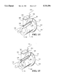
- FIG. 6 is a perspective view of an embodiment of the composite cutter of FIG. 2.
- FIG. 7 is an exploded view of the composite cutter of FIG. 6.
- FIG. 8 is a cross-sectional view of an embodiment of the composite cutter of FIG. 6 as seen along the line 8--8.
- FIG. 9 is an exploded perspective view of an embodiment of the sensor mount of the composite cutter of FIG. 6.
- FIG. 10 is an exploded perspective view of another embodiment of the sensor mount of the composite cutter of FIG. 6.
- FIG. 11 is a perspective view of an embodiment of the composite cutter of FIG. 2.
- FIG. 12 is an exploded view of the composite cutter of FIG. 11.
- FIG. 13 is a cross-sectional view of an embodiment of the composite cutter of FIG. 11 as seen along the line 13--13.
- FIG. 14 is an exploded perspective view of an embodiment of the sensor mount of the composite cutter of FIG. 11.
- FIG. 15 is an exploded perspective view of another embodiment of the sensor mount of the composite cutter of FIG. 11.
- FIG. 16 is an exploded perspective view of an embodiment of the composite cutter of FIG. 2.
- FIG. 17 is an exploded side view of the composite cutter of FIG. 16.
- an atherectomy catheter 102 having a cutter housing 104, a window 106, a composite cutter 100, a nose cone 110, a cutter torque cable 126 and a guide wire 108 is shown.
- the cutter housing 104 encloses the composite cutter 100.
- the window 106 of the cutter housing 104 aligns with the composite cutter 100.
- the nose cone 110 attaches to the cutter housing 104.
- the guide wire 108 extends through the atherectomy catheter and beyond the nosecone 110.
- the atherectomy catheter 102 is inserted into the vascular system of a patient.
- the window 106 invaginates material from the interior wall of a blood vessel.
- the composite cutter 100 reciprocates within the housing and severs the invaginated material.
- the severed material is stored in the nosecone 110.
- An example of an operable atherectomy catheter and the use thereof is disclosed by Gifford III et al. in U.S. Pat. No. 5,471,125, entitled “Atherectomy Catheter and Method of Forming the Same", the disclosure of which is incorporated herein by reference.
- the operation of a sensor with an atherectomy cutter is disclosed in U.S. Pat. No. 5,427,107, issued Jun. 27, 1995 to Milo et al., entitled “Optical Encoder for Catheter Device", which is commonly assigned and incorporated herein by reference.
- the cutter torque cable 126 extends axially through the composite cutter 100 and the cutter torque cable 126.
- the composite cutter 100 includes a sensor mount 130 and a cutter 140.
- the cutter 140 has a cutting edge 112.
- the composite cutter 100 aligns coaxially with and attaches to the cutter torque cable 126.
- the cutting edge 112 has an arcuate shape.
- the cutting edge 112 is sharp, being between 5-10 microns thick.
- the cutting edge 112 has a hardness relatively greater than the hardness of the sensor mount 130.
- a cutting edge 112 having a Rockwell "A" hardness of 90, or harder is preferred because such an edge is hard enough to cut calcified plaque from a biological conduit.
- the sensor mount 130 is fabricated from a machinable grade of stainless steel and the cutting edge 112 is fabricated from tungsten carbide.
- the cutting edge 112 can be of various shapes and configurations.
- the cutting edge 112 can be configured having cutting surfaces of types described in co-pending in U.S. Pat. No. 5,507,760, Issue Date, Apr. 16, 1996 to Wynne et al., entitled “Cutter Device”which is commonly assigned and incorporated herein by reference.
- the composite cutter 100 is generally cylindrical in shape.
- the composite cutter 100 includes a middle portion 105 which is relatively narrower than the remainder of the composite cutter 100.
- the atherectomy 102 When the atherectomy 102 (see FIG. 1) inserts into a biological conduit (e.g. a blood vessel) and window 106 aligns adjacent to stenotic material, an operator manipulates the cutter torque cable 126 to reciprocate the composite cutter 100.
- a motor drive unit (not shown) rotates the cutter torque cable 126.
- the composite cutter 100 and cutter torque cable 126 are designed to rotate within the range of 1500-2500 revolutions per minute (RPM).
- RPM revolutions per minute
- An example of a cutter torque cable 126 is described in copending U.S. patent application Ser. No. 08/606,678, filed Feb.
- the sensor mount 130 has a proximal end 132, a distal end 134, an interior 142 and a tapered portion 135.
- the cutter 140 has a proximal end 139, a distal end 138 having a cutting edge 112, an interior surface 162, and a faded portion 137.
- the proximal end 132 of the sensor mount 130 is attachable to a cutter torque cable (see FIG. 2).
- the tapered portion 135 of the sensor mount 130 connects with the faded portion 137 of the cutter 140.
- Tapered for the purposes of the present invention, means a male connector having an end with a narrow diameter which slopes to a relatively wider diameter, the tapered slope being constant.
- Faded for the purposes of the present invention means a female connector having an open mouth with an end having a wide diameter which slopes to a relatively narrower inner diameter, the faded slope being constant.
- the tapered portion 135 of the sensor mount 130 mechanically interlocks (i.e. forms a mechanical force-fit) with the faded portion 137 of the cutter 140.
- the cutter 140 and the sensor mount 130 interconnect in coaxial alignment.
- the interconnection between the sensor mount 130 and cutter 140 is reinforced by any of a number of interconnection techniques (processes) such as brazing, welding, soldering or adhesive bonding.
- the interconnection between the sensor mount 130 and the cutter 140 protects, aligns and holds the sensor 164 relative to the cutter 140 during operation of the composite cutter.
- FIG. 4 there is shown an exploded side view of the composite cutter 100 depicted in FIG. 3.
- the sensor mount 130 and the cutter 140 join together in the direction of the arrow 113.
- the proximal end 132 of the sensor mount 130 has an attachment hole 156.
- the attachment hole 156 facilitates the selected process which interconnects the sensor mount 130 and the cutter torque cable 126 e.g. soldering, brazing, or welding.
- the sensor 164 is positioned within the interior 142 of the sensor mount 130.
- the sensor 164 attaches to the interior 142 by adhesive bonding for example.
- An opening 154 is defined on the surface 152 of the middle portion 105 of the composite cutter 100.
- the opening 154 is circular in shape.
- the sensor 164 is circular in shape and fits within the opening 154.
- the opening 154 is defined on the sensor mount 130 and permits sensory communication between the sensor 164 and the environment which surrounds the composite cutter 100.
- the tapered portion 135 of the sensor mount 130 is formed with at least one external spline 117.
- the faded portion 137 of the cutter 140 is formed with at least one internal spline 115.
- the internal spline 115 and the external spline 117 mechanically interlock.
- the sensor mount 130 includes an annular recess 119 which circumscribes the external spline 117.
- the proximal end 139 of the cutter 140 includes an annular lock 121.
- the annular lock 121 snaps into the annular recess 119.
- FIG. 6 an embodiment of the composite cutter 100 is shown.
- a portion of the proximal end 139 of the cutter 140 and the sensor mount 130 are cut away to show an opening 160 which is defined by the proximal end 139.
- the opening 160 is adaptable for receiving, and bonding to, the cutter torque cable 126 (see FIG. 2).
- the cutter 140 is machined to form an opening 154 having a periphery 137.
- the opening 154 permits communication between the sensor 164 (see FIG. 9 and FIG. 10) and the environment surrounding the cutter 140.
- the sensor mount 130 and the cutter 140 cooperate to protect the sensor 164 from damage, hold the sensor 164, and align the sensor 164 relative to the cutting edge 112 of the cutter 140.
- FIG. 7 there is shown an exploded view of the composite cutter 100 of FIG. 6.
- An arrow 109 indicates that the sensor mount 130 inserts into the cutter 140 via the distal end 138 where the cutting edge 112 is situated.
- the proximal end 139 of the cutter 140 has a rounded edge 158.
- the rounded edge 158 permits the cutter 140 to slide against biological tissue which may enter the cutter housing 104 during use of the atherectomy catheter 102 (see FIG. 1).
- the cutter 140 includes a proximal end 139, an interior surface 162, a distal end 138 and a ridge 172.
- the sensor mount 130 includes a proximal end 132, a distal end 134, and an interior 142.
- the sensor mount 130 attaches coaxially within the cutter 130.
- the interior 142 of the sensor mount 130 is cylindrical shaped, being configured for circumscribing the cutter torque cable 126 and being adaptable for attachment to the cutter torque cable 126.
- the ridge 172 is formed on the interior surface 162 of the cutter 140 near the distal end 138 of the cutter 140.
- the ridge 172 contacts the distal end 134 of the sensor mount 130.
- the proximal end 139 of the cutter 140 contacts the proximal end 132 of the sensor mount 130.
- the ridge 172 and the proximal end 139 of the cutter 140 cooperate with the distal end 134 and the proximal end 132 of the sensor mount 130 respectively to hold the cutter 140 and the sensor mount 130 together.
- the outer surface 152 of the sensor mount 130 bonds to the interior surface 162 of the cutter 140.
- each sensor mount 130 has a support 136.
- Each support 136 is machined into the exterior surface of the sensor mount 130.
- the sensor 164 is attachable with each support 136 by an adhesive bond.
- the support 136 is appropriately configured, having a rectangular shape, to coincide with the shape of sensor 164.
- the sensor 164 and the sensor mount 130 are sealed in a cover (not shown) such as a plastic wrap to protect the sensor 164 during use.
- the sensor 164 communicates with an operator electronically via a wire 170 (partially shown) included with the sensor 164.
- the wire 170 extends from the sensor 164, through the opening 160 (see FIG. 6) and along the atherectomy catheter 102 (see FIG. 1) to appropriate signal processing equipment.
- sensor mount 130 where the support 136 is a trough which cuts through the surface 152 into the interior 142 of the sensor mount 130.
- the sensor includes a periphery 184 and sides 182. Edges 168 of the support 136 hold the sensor 164 and bond to the sensor 164 at appropriate regions such as the side 182 and periphery 184 of the sensor 164.
- the proximal end 132 of the sensor housing 130 is rounded to conform in shape to the inner surface 162 of the cutter 140 (see FIG. 8).
- FIG. 10 there is shown a variation of an embodiment of sensor mount 130 of FIG. 9 where the support 136 is a trough formed on the surface 152 of sensor mount 130.
- the support 136 includes a flat portion 186.
- the sensor 164 bonds with the flat portion 186 of the support 136.
- the sensor mount 130 attaches within the cutter 140. A portion of the sensor mount 130 and the proximal end 139 of the cutter 140 are cut away to show the hole 160.
- the hole 160 is formed through the proximal end 139 of the cutter for circumscribing the cutter torque cable 126 when the cutter 140 bonds with the cutter torque cable 126.
- the cutter 140 defines a hole 154 having a periphery 137.
- FIG. 12 there is shown an exploded side view of the composite cutter 100 of FIG. 11.
- An arrow 111 indicates that the sensor mount 130 inserts into the cutter 140 via proximal end 139 of the cutter 140.
- a portion of the surface 152 of the sensor mount 130 is machined to form the support 136.
- the opening 154 is defined in the cutter 140.
- the opening 154 permits communication between the sensor 164 (shown in FIG. 14 and FIG. 15) and the environment which surrounds the composite cutter 100.
- the cutter 140 has a proximal end 139, an interior surface 162 having a seat 178, and a distal end 138.
- the sensor mount 130 includes a surface 152 and a cap 175 formed with a rounded edge 174 and an annular shoulder 176.
- the cap 175 is affixed at the proximal end 132 of the sensor mount 130.
- the surface 152 of the sensor mount bonds with the interior surface 162 of the cutter 140.
- the cap 175 of the sensor mount 130 contacts the proximal end 139 of the cutter 140.
- the distal end 138 of the sensor mount 130 contacts the seat 178.
- the seat 178 has an arcuate geometry which meets securely with the distal end 138.
- the interior surface 162, the proximal end 130, and the seat 178 of the cutter 140 cooperate to hold the sensor mount 130.
- sensor mount 130 is shown having a sensor 164 positioned adjacent the support 136.
- the support 136 is adaptable to conform with the shape of the sensor 164 (i.e. includes a geometry capable of holding the sensor 164).
- Both the support 136 and the sensor 164 are rectangular shaped and are adhesively bonded together.
- the sensor 164 communicates with an operator electronically via a wire 170 included with sensor 164.
- the wire 170 extends from sensor 164, along a conduit 180 formed through cap 175 and out through the atherectomy catheter 102 to electrically communicate with a sensor system (not shown).
- the support 136 is a trough formed in the surface 152 of sensor mount 130.
- the sensor 164 bonds to the flat portion 186 of the support 136.
- the support 136 is a trough which cuts into the interior 142 of sensor mount 130.
- the edges 168 hold the sensor 164 in place and provide a bonding surface. More particularly, the edges 168 bond to appropriate regions of the sensor 164 such as the side 182 and periphery 184.
- the cutter 140 includes an annular face 188, a cylindrical extension 190, an annular ring 192 and a guide 196.
- the cylindrical extension 190 extends perpendicularly from the annular face 188 of the cutter 140.
- the annular ring 192 circumscribes the cylindrical extension 190.
- the cylindrical extension 190 is adaptable to circumscribe and bond with the cutter torque cable 126.
- the sensor mount 130 includes an internal annular groove 194.
- the annular ring 192 of the cylindrical extension 190 snaps into the internal annular groove 194 in the sensor mount 130 to mechanically interconnect the sensor mount 130 and the cutter 140.
- the sensor mount 130 is fabricated from a plastic and attaches to the cutter torque cable 126 via heat bonding.
- the sensor mount is fabricated from a material selected from the following group: poly-carbonate and poly-propylene.
- the cylindrical extension 190 extends perpendicularly from annular face 188 of the cutter 140.
- the cylindrical extension 190 attaches with the sensor mount 130 and includes a hollow interior for receiving and bonding with the cutter torque cable 126.
- the cylindrical extension 190 includes a guide 196.
- the guide 196 includes a triangular cross-section which extends between the annular face 188 and the cylindrical extension 190.
- the guide 196 contacts with the edge 198 of the opening 154 and aligns the sensor mount 130 into a desired position with the cutter 140.
- the guide 196 contacts the sensor mount 130 so that the sensor mount 130 and the cutter 140 rotate together.
- the guide 196 may include a reflective coating to reflect ultrasonic energy radiated by the sensor 164.
- the sensor 164 is shown between the cutter 140 and the sensor mount 130. Communication between the sensor 164 and the environment surrounding the composite cutter is established via the opening 154. Electronic communication is established between the sensor 164 and a sensor system via the wire 170 (shown in part) which passes through the sensor mount 130, the opening 160 and through the atherectomy catheter 102 (see FIG. 1).
- the cutter 140 has an edge 199 and the sensor mount 130 has an edge 198.
- the edges 198 and the edge 199 conform to the shape of the sensor 164.
- the edge 198 and the edge 199 are configured to hold the sensor 164.
- the sensor 164 adhesively bonds to the edge 198 and to the edge 199.
- An arrow 115 indicates the direction in which the sensor mount 130 mates with the cutter 140.
- the sensor mount 130 attaches to the cutter 140 via injection molding.
- the sensor mount 130 bonds to the support 136 adhesively.
- a bonding method may first be chosen for the cutter 140 and the sensor mount 130 which is based on the material composition of the parts to be joined.
- the sensor mount 130 and the cutter 140 are then configured having an appropriate geometry, suitable for the chosen bonding method in accordance with industry standards and practical cost constraints. With any geometry, however, precise alignment between the sensor mount 130 and the cutter 140 is desirable.
- the sensor mount 130 is fabricated from a machinable or conformable material which is adaptable to provide an appropriate support 136 for a sensor, or a sensor system for example.
- the cutter 140 is fabricated from a material of an appropriate hardness to resist deformation such as dulling. Materials such as diamond, cubic boron nitride and other materials could be used to form portions of the cutter such as the cutting edge 112.
- An appropriate coating can be applied to the composite cutter 100, or portions thereof, for increased bio-compatibility or wear resistance, for example.
- the cutter 140 has a coating of titanium nitride.
- FIG. 17 an exploded view of the composite cutter 100 of FIG. 16 is shown.
- An arrow 113 indicates the direction in which the sensor mount 130 connects with the cutter 140 via proximal end 139.
- a portion of the surface 152 of the sensor mount 130 is machined to form the support 136 which includes the opening 154.
- the support 136 can be adapted to coincide with the shape of a square, or circular shaped sensor.
- the support can be formed within the cutter 140, on the sensor mount 130, or any other suitable alternative which holds the sensor 164 and permits communication between the sensor 164 and the environment.
- a sensor capable of generating and communicating a description of the interior of a blood vessel is employed by the present invention.
- the sensor 164 is an ultrasonic transducer which is capable of determining the density of surrounding tissues during operation of the present invention.
- the sensor 164 communicates with an operator by the wire 170 which may be wrapped about the surface 152 of the sensor mount and securely held by, for example, a plastic wrap, or an adhesive.
- the wire 170 extends through the atherectomy catheter 102 to establish electronic communication with an operator.
Abstract
Description
Claims (16)
Priority Applications (2)
| Application Number | Priority Date | Filing Date | Title |
|---|---|---|---|
| US08/597,603 US5733296A (en) | 1996-02-06 | 1996-02-06 | Composite atherectomy cutter |
| US08/895,106 US6120515A (en) | 1996-02-06 | 1997-07-16 | Composite atherectomy cutter |
Applications Claiming Priority (1)
| Application Number | Priority Date | Filing Date | Title |
|---|---|---|---|
| US08/597,603 US5733296A (en) | 1996-02-06 | 1996-02-06 | Composite atherectomy cutter |
Related Child Applications (1)
| Application Number | Title | Priority Date | Filing Date |
|---|---|---|---|
| US08/895,106 Division US6120515A (en) | 1996-02-06 | 1997-07-16 | Composite atherectomy cutter |
Publications (1)
| Publication Number | Publication Date |
|---|---|
| US5733296A true US5733296A (en) | 1998-03-31 |
Family
ID=24392190
Family Applications (2)
| Application Number | Title | Priority Date | Filing Date |
|---|---|---|---|
| US08/597,603 Expired - Lifetime US5733296A (en) | 1996-02-06 | 1996-02-06 | Composite atherectomy cutter |
| US08/895,106 Expired - Fee Related US6120515A (en) | 1996-02-06 | 1997-07-16 | Composite atherectomy cutter |
Family Applications After (1)
| Application Number | Title | Priority Date | Filing Date |
|---|---|---|---|
| US08/895,106 Expired - Fee Related US6120515A (en) | 1996-02-06 | 1997-07-16 | Composite atherectomy cutter |
Country Status (1)
| Country | Link |
|---|---|
| US (2) | US5733296A (en) |
Cited By (68)
| Publication number | Priority date | Publication date | Assignee | Title |
|---|---|---|---|---|
| US6159225A (en) * | 1995-10-13 | 2000-12-12 | Transvascular, Inc. | Device for interstitial transvascular intervention and revascularization |
| US6190353B1 (en) | 1995-10-13 | 2001-02-20 | Transvascular, Inc. | Methods and apparatus for bypassing arterial obstructions and/or performing other transvascular procedures |
| US20010004700A1 (en) * | 1998-04-10 | 2001-06-21 | Honeycutt John S. | Rotational atherectomy device |
| US6299622B1 (en) * | 1999-08-19 | 2001-10-09 | Fox Hollow Technologies, Inc. | Atherectomy catheter with aligned imager |
| US6302875B1 (en) | 1996-10-11 | 2001-10-16 | Transvascular, Inc. | Catheters and related devices for forming passageways between blood vessels or other anatomical structures |
| US6319242B1 (en) * | 1997-02-12 | 2001-11-20 | Prolifix Medical, Inc. | Apparatus and method for controlled removal of stenotic material from stents |
| US6447525B2 (en) | 1999-08-19 | 2002-09-10 | Fox Hollow Technologies, Inc. | Apparatus and methods for removing material from a body lumen |
| WO2002049690A3 (en) * | 2000-12-20 | 2002-09-19 | Fox Hollow Technologies Inc | Debulking catheter |
| US20030120295A1 (en) * | 2000-12-20 | 2003-06-26 | Fox Hollow Technologies, Inc. | Debulking catheters and methods |
| US20030125757A1 (en) * | 2000-12-20 | 2003-07-03 | Fox Hollow Technologies, Inc. | Debulking catheters and methods |
| US6602264B1 (en) | 1997-07-24 | 2003-08-05 | Rex Medical, L.P. | Rotational thrombectomy apparatus and method with standing wave |
| US20030191483A1 (en) * | 2002-04-04 | 2003-10-09 | Rex Medical | Thrombectomy device with multi-layered rotational wire |
| US6638233B2 (en) | 1999-08-19 | 2003-10-28 | Fox Hollow Technologies, Inc. | Apparatus and methods for material capture and removal |
| US6709444B1 (en) * | 1996-02-02 | 2004-03-23 | Transvascular, Inc. | Methods for bypassing total or near-total obstructions in arteries or other anatomical conduits |
| US20040167553A1 (en) * | 2000-12-20 | 2004-08-26 | Fox Hollow Technologies, Inc. | Methods and devices for cutting tissue |
| US20040167554A1 (en) * | 2000-12-20 | 2004-08-26 | Fox Hollow Technologies, Inc. | Methods and devices for reentering a true lumen from a subintimal space |
| US20050154407A1 (en) * | 2000-12-20 | 2005-07-14 | Fox Hollow Technologies, Inc. | Method of evaluating drug efficacy for treating atherosclerosis |
| US20050177068A1 (en) * | 2000-12-20 | 2005-08-11 | Fox Hollow Technologies, Inc. | Debulking catheters and methods |
| US20050222663A1 (en) * | 2000-12-20 | 2005-10-06 | Fox Hollow Technologies, Inc. | Debulking catheters and methods |
| US20060074441A1 (en) * | 1997-07-24 | 2006-04-06 | Rex Medical, L.P. | Rotational thrombectomy device |
| US20060236019A1 (en) * | 2005-04-19 | 2006-10-19 | Fox Hollow Technologies, Inc. | Libraries and data structures of materials removed by debulking catheters |
| US20060235366A1 (en) * | 2000-12-20 | 2006-10-19 | Fox Hollow Technologies, Inc. | Method of evaluating a treatment for vascular disease |
| US20060239982A1 (en) * | 2000-12-20 | 2006-10-26 | Fox Hollow Technologies, Inc. | Debulking catheters and methods |
| US20060259052A1 (en) * | 1998-04-10 | 2006-11-16 | Rafael Pintor | Neuro thrombectomy catheter |
| US20060264989A1 (en) * | 1999-10-22 | 2006-11-23 | Rex Medical, L.P. | Double balloon thrombectomy catheter |
| US20070038173A1 (en) * | 2005-07-27 | 2007-02-15 | Fox Hollow Technologies, Inc. | Methods affecting markers in patients having vascular disease |
| US20070078469A1 (en) * | 2000-12-20 | 2007-04-05 | Fox Hollow Technologies, Inc | Testing a patient population having a cardiovascular condition for drug efficacy |
| US20070196926A1 (en) * | 2006-02-17 | 2007-08-23 | Fox Hollow Technologies, Inc. | Testing lumenectomy samples for Markers of non-vascular diseases |
| US20090276023A1 (en) * | 2008-04-30 | 2009-11-05 | Medtronic, Inc. | Techniques for placing medical leads for electrical stimulation of nerve tissue |
| US20100121357A1 (en) * | 1995-10-13 | 2010-05-13 | Medtronic Vascular, Inc. | Tissue Penetrating Catheters having Integral Imaging Transducers and Their Methods of Use |
| US7771445B2 (en) | 1998-04-10 | 2010-08-10 | Ev3 Endovascular, Inc. | Rotational atherectomy system with stationary cutting elements |
| US7887556B2 (en) | 2000-12-20 | 2011-02-15 | Fox Hollow Technologies, Inc. | Debulking catheters and methods |
| US20110040314A1 (en) * | 1999-10-22 | 2011-02-17 | Mcguckin Jr James F | Rotational Thrombectomy Wire With Blocking Device |
| US20110236902A1 (en) * | 2004-12-13 | 2011-09-29 | Tyco Healthcare Group Lp | Testing a patient population having a cardiovascular condition for drug efficacy |
| US8192452B2 (en) | 2009-05-14 | 2012-06-05 | Tyco Healthcare Group Lp | Easily cleaned atherectomy catheters and methods of use |
| US8246640B2 (en) | 2003-04-22 | 2012-08-21 | Tyco Healthcare Group Lp | Methods and devices for cutting tissue at a vascular location |
| US8328829B2 (en) | 1999-08-19 | 2012-12-11 | Covidien Lp | High capacity debulking catheter with razor edge cutting window |
| US8414604B2 (en) | 2008-10-13 | 2013-04-09 | Covidien Lp | Devices and methods for manipulating a catheter shaft |
| US8496677B2 (en) | 2009-12-02 | 2013-07-30 | Covidien Lp | Methods and devices for cutting tissue |
| US8784440B2 (en) | 2008-02-25 | 2014-07-22 | Covidien Lp | Methods and devices for cutting tissue |
| US8808186B2 (en) | 2010-11-11 | 2014-08-19 | Covidien Lp | Flexible debulking catheters with imaging and methods of use and manufacture |
| US8920450B2 (en) | 2010-10-28 | 2014-12-30 | Covidien Lp | Material removal device and method of use |
| US8992717B2 (en) | 2011-09-01 | 2015-03-31 | Covidien Lp | Catheter with helical drive shaft and methods of manufacture |
| US9028512B2 (en) | 2009-12-11 | 2015-05-12 | Covidien Lp | Material removal device having improved material capture efficiency and methods of use |
| US9119662B2 (en) | 2010-06-14 | 2015-09-01 | Covidien Lp | Material removal device and method of use |
| US9456843B2 (en) | 2014-02-03 | 2016-10-04 | Covidien Lp | Tissue-removing catheter including angular displacement sensor |
| US9526519B2 (en) | 2014-02-03 | 2016-12-27 | Covidien Lp | Tissue-removing catheter with improved angular tissue-removing positioning within body lumen |
| US9532844B2 (en) | 2012-09-13 | 2017-01-03 | Covidien Lp | Cleaning device for medical instrument and method of use |
| US9597110B2 (en) | 2012-11-08 | 2017-03-21 | Covidien Lp | Tissue-removing catheter including operational control mechanism |
| US9687266B2 (en) | 2009-04-29 | 2017-06-27 | Covidien Lp | Methods and devices for cutting and abrading tissue |
| US9801647B2 (en) | 2006-05-26 | 2017-10-31 | Covidien Lp | Catheter including cutting element and energy emitting element |
| US9943329B2 (en) | 2012-11-08 | 2018-04-17 | Covidien Lp | Tissue-removing catheter with rotatable cutter |
| US10213224B2 (en) | 2014-06-27 | 2019-02-26 | Covidien Lp | Cleaning device for catheter and catheter including the same |
| US10292721B2 (en) | 2015-07-20 | 2019-05-21 | Covidien Lp | Tissue-removing catheter including movable distal tip |
| US10314664B2 (en) | 2015-10-07 | 2019-06-11 | Covidien Lp | Tissue-removing catheter and tissue-removing element with depth stop |
| US10314667B2 (en) | 2015-03-25 | 2019-06-11 | Covidien Lp | Cleaning device for cleaning medical instrument |
| US10463387B2 (en) | 2011-09-13 | 2019-11-05 | John P. Pigott | Intravascular catheter having an expandable incising portion for incising atherosclerotic material located in a blood vessel |
| US10485572B2 (en) | 2011-09-13 | 2019-11-26 | John P. Pigott | Intravascular catheter having an expandable incising portion |
| US10603069B2 (en) | 2015-01-13 | 2020-03-31 | John P. Pigott | Intravascular catheter balloon device having a tool for atherectomy or an incising portion for atheromatous plaque scoring |
| US10610255B2 (en) | 2011-09-13 | 2020-04-07 | John P. Pigott | Intravascular catheter having an expandable incising portion and medication delivery system |
| US10828471B2 (en) | 2013-07-15 | 2020-11-10 | John P. Pigott | Balloon catheter having a retractable sheath |
| US11033712B2 (en) | 2015-01-13 | 2021-06-15 | Venturemed Group, Inc. | Intravascular catheter having an expandable portion |
| US11154694B2 (en) | 2013-07-15 | 2021-10-26 | John P. Pigott | Balloon catheter having a retractable sheath and locking mechanism with balloon recapture element |
| US11154693B2 (en) | 2013-07-15 | 2021-10-26 | John P. Pigott | Balloon catheter having a retractable sheath |
| US11202892B2 (en) | 2013-07-15 | 2021-12-21 | John P. Pigott | Balloon catheter having a retractable sheath |
| US11357533B2 (en) | 2011-09-13 | 2022-06-14 | Venturemed Group, Inc. | Intravascular catheter having an expandable incising portion and abrasive surfaces |
| US11413062B2 (en) | 2011-09-13 | 2022-08-16 | Venturemed Group, Inc. | Methods for preparing a zone of attention within a vascular system for subsequent angioplasty with an intravascular catheter device having an expandable incising portion and an integrated embolic protection device |
| US11559325B2 (en) | 2011-09-13 | 2023-01-24 | Venturemed Group, Inc. | Intravascular catheter having an expandable incising portion and grating tool |
Families Citing this family (61)
| Publication number | Priority date | Publication date | Assignee | Title |
|---|---|---|---|---|
| US20030236533A1 (en) * | 2002-06-20 | 2003-12-25 | The Regents Of The University Of California | Shape memory polymer actuator and catheter |
| US9955994B2 (en) | 2002-08-02 | 2018-05-01 | Flowcardia, Inc. | Ultrasound catheter having protective feature against breakage |
| US7335180B2 (en) | 2003-11-24 | 2008-02-26 | Flowcardia, Inc. | Steerable ultrasound catheter |
| DE10249643A1 (en) * | 2002-10-24 | 2004-05-13 | Siemens Ag | Coronary heart disease diagnosis and treatment method in which plaque deposition in blood vessels of interest is monitored over time and compared with reference values stored in the memory of a data processing unit |
| US7758510B2 (en) | 2003-09-19 | 2010-07-20 | Flowcardia, Inc. | Connector for securing ultrasound catheter to transducer |
| US7744604B2 (en) * | 2003-11-13 | 2010-06-29 | Lawrence Livermore National Security, Llc | Shape memory polymer medical device |
| US8882786B2 (en) * | 2004-02-17 | 2014-11-11 | Lawrence Livermore National Security, Llc. | System for closure of a physical anomaly |
| US20050209610A1 (en) * | 2004-03-03 | 2005-09-22 | Scimed Life Systems, Inc. | Radially adjustable tissue removal device |
| US20050197661A1 (en) * | 2004-03-03 | 2005-09-08 | Scimed Life Systems, Inc. | Tissue removal probe with sliding burr in cutting window |
| US8784421B2 (en) | 2004-03-03 | 2014-07-22 | Boston Scientific Scimed, Inc. | Apparatus and methods for removing vertebral bone and disc tissue |
| US20050261692A1 (en) * | 2004-05-21 | 2005-11-24 | Scimed Life Systems, Inc. | Articulating tissue removal probe and methods of using the same |
| US8328810B2 (en) | 2004-06-17 | 2012-12-11 | Boston Scientific Scimed, Inc. | Slidable sheaths for tissue removal devices |
| US9051411B2 (en) | 2004-08-16 | 2015-06-09 | Lawrence Livermore National Security, Llc | Shape memory polymers |
| US11820852B2 (en) | 2004-08-16 | 2023-11-21 | Lawrence Livermore National Security, Llc | Shape memory polymers |
| US20070239140A1 (en) * | 2006-03-22 | 2007-10-11 | Revascular Therapeutics Inc. | Controller system for crossing vascular occlusions |
| US8246643B2 (en) | 2006-11-07 | 2012-08-21 | Flowcardia, Inc. | Ultrasound catheter having improved distal end |
| US20090240121A1 (en) * | 2008-03-21 | 2009-09-24 | Nova Biomedical Corporation | Intravascular sensor and insertion set combination |
| US9498600B2 (en) | 2009-07-01 | 2016-11-22 | Avinger, Inc. | Atherectomy catheter with laterally-displaceable tip |
| US8062316B2 (en) | 2008-04-23 | 2011-11-22 | Avinger, Inc. | Catheter system and method for boring through blocked vascular passages |
| US9125562B2 (en) | 2009-07-01 | 2015-09-08 | Avinger, Inc. | Catheter-based off-axis optical coherence tomography imaging system |
| US8657821B2 (en) | 2008-11-14 | 2014-02-25 | Revascular Therapeutics Inc. | Method and system for reversibly controlled drilling of luminal occlusions |
| US8162891B2 (en) | 2008-11-26 | 2012-04-24 | Revascular Therapeutics, Inc. | Delivery and exchange catheter for storing guidewire |
| EP2424608B1 (en) | 2009-04-28 | 2014-03-19 | Avinger, Inc. | Guidewire support catheter |
| AU2010253912B2 (en) | 2009-05-28 | 2015-03-05 | Avinger, Inc. | Optical Coherence Tomography for biological imaging |
| EP2509498B1 (en) | 2009-12-08 | 2020-09-16 | Avinger, Inc. | Devices for predicting and preventing restenosis |
| US9023070B2 (en) | 2010-05-13 | 2015-05-05 | Rex Medical, L.P. | Rotational thrombectomy wire coupler |
| US8663259B2 (en) | 2010-05-13 | 2014-03-04 | Rex Medical L.P. | Rotational thrombectomy wire |
| US8764779B2 (en) | 2010-05-13 | 2014-07-01 | Rex Medical, L.P. | Rotational thrombectomy wire |
| US9795406B2 (en) | 2010-05-13 | 2017-10-24 | Rex Medical, L.P. | Rotational thrombectomy wire |
| US11382653B2 (en) | 2010-07-01 | 2022-07-12 | Avinger, Inc. | Atherectomy catheter |
| JP2013531542A (en) | 2010-07-01 | 2013-08-08 | アビンガー・インコーポレイテッド | An atherectomy catheter having a longitudinally movable drive shaft |
| WO2014039096A1 (en) | 2012-09-06 | 2014-03-13 | Avinger, Inc. | Re-entry stylet for catheter |
| EP2691038B1 (en) | 2011-03-28 | 2016-07-20 | Avinger, Inc. | Occlusion-crossing devices, imaging, and atherectomy devices |
| US9949754B2 (en) | 2011-03-28 | 2018-04-24 | Avinger, Inc. | Occlusion-crossing devices |
| EP2768406B1 (en) | 2011-10-17 | 2019-12-04 | Avinger, Inc. | Atherectomy catheters and non-contact actuation mechanism for catheters |
| US9345406B2 (en) | 2011-11-11 | 2016-05-24 | Avinger, Inc. | Occlusion-crossing devices, atherectomy devices, and imaging |
| US9603615B2 (en) | 2012-01-18 | 2017-03-28 | C.R. Bard, Inc. | Vascular re-entry device |
| EP2849660B1 (en) | 2012-05-14 | 2021-08-25 | Avinger, Inc. | Atherectomy catheter drive assemblies |
| US11406412B2 (en) | 2012-05-14 | 2022-08-09 | Avinger, Inc. | Atherectomy catheters with imaging |
| WO2013172972A1 (en) | 2012-05-14 | 2013-11-21 | Avinger, Inc. | Optical coherence tomography with graded index fiber for biological imaging |
| EP2879596A2 (en) | 2012-08-02 | 2015-06-10 | Flowcardia, Inc. | Ultrasound catheter system |
| US11284916B2 (en) | 2012-09-06 | 2022-03-29 | Avinger, Inc. | Atherectomy catheters and occlusion crossing devices |
| WO2015120146A1 (en) | 2014-02-06 | 2015-08-13 | Avinger, Inc. | Atherectomy catheters and occlusion crossing devices |
| US9498247B2 (en) | 2014-02-06 | 2016-11-22 | Avinger, Inc. | Atherectomy catheters and occlusion crossing devices |
| EP2892448B1 (en) | 2012-09-06 | 2020-07-15 | Avinger, Inc. | Balloon atherectomy catheters with imaging |
| WO2014143064A1 (en) | 2013-03-15 | 2014-09-18 | Avinger, Inc. | Chronic total occlusion crossing devices with imaging |
| EP2967507B1 (en) | 2013-03-15 | 2018-09-05 | Avinger, Inc. | Tissue collection device for catheter |
| WO2014142958A1 (en) | 2013-03-15 | 2014-09-18 | Avinger, Inc. | Optical pressure sensor assembly |
| US10130386B2 (en) | 2013-07-08 | 2018-11-20 | Avinger, Inc. | Identification of elastic lamina to guide interventional therapy |
| US10357277B2 (en) | 2014-07-08 | 2019-07-23 | Avinger, Inc. | High speed chronic total occlusion crossing devices |
| JP6896699B2 (en) | 2015-07-13 | 2021-06-30 | アビンガー・インコーポレイテッドAvinger, Inc. | Microformed anamorphic reflector lens for image-guided therapy / diagnostic catheter |
| CN108882857A (en) | 2016-01-25 | 2018-11-23 | 阿维格公司 | With the modified OCT image conduit of lag |
| EP3435892B1 (en) | 2016-04-01 | 2024-04-03 | Avinger, Inc. | Atherectomy catheter with serrated cutter |
| CN109475368A (en) | 2016-06-03 | 2019-03-15 | 阿维格公司 | Conduit device with detachable distal end |
| US11224459B2 (en) | 2016-06-30 | 2022-01-18 | Avinger, Inc. | Atherectomy catheter with shapeable distal tip |
| US20180140321A1 (en) | 2016-11-23 | 2018-05-24 | C. R. Bard, Inc. | Catheter With Retractable Sheath And Methods Thereof |
| US11596726B2 (en) | 2016-12-17 | 2023-03-07 | C.R. Bard, Inc. | Ultrasound devices for removing clots from catheters and related methods |
| US10582983B2 (en) | 2017-02-06 | 2020-03-10 | C. R. Bard, Inc. | Ultrasonic endovascular catheter with a controllable sheath |
| EP4044942A4 (en) | 2019-10-18 | 2023-11-15 | Avinger, Inc. | Occlusion-crossing devices |
| US20210145474A1 (en) * | 2019-11-20 | 2021-05-20 | Boston Scientific Scimed, Inc. | Composite atherectomy burr |
| CN110916768A (en) * | 2019-11-29 | 2020-03-27 | 昆山金泰医疗科技有限公司 | High-efficient spiral shell rotary-cut bolt device |
Citations (27)
| Publication number | Priority date | Publication date | Assignee | Title |
|---|---|---|---|---|
| US4669469A (en) * | 1986-02-28 | 1987-06-02 | Devices For Vascular Intervention | Single lumen atherectomy catheter device |
| US4771774A (en) * | 1986-02-28 | 1988-09-20 | Devices For Vascular Intervention, Inc. | Motor drive unit |
| US4781186A (en) * | 1984-05-30 | 1988-11-01 | Devices For Vascular Intervention, Inc. | Atherectomy device having a flexible housing |
| US4794931A (en) * | 1986-02-28 | 1989-01-03 | Cardiovascular Imaging Systems, Inc. | Catheter apparatus, system and method for intravascular two-dimensional ultrasonography |
| US4883458A (en) * | 1987-02-24 | 1989-11-28 | Surgical Systems & Instruments, Inc. | Atherectomy system and method of using the same |
| US4886490A (en) * | 1984-05-14 | 1989-12-12 | Surgical Systems & Instruments, Inc. | Atherectomy catheter system and method of using the same |
| US4979951A (en) * | 1984-05-30 | 1990-12-25 | Simpson John B | Atherectomy device and method |
| US4979939A (en) * | 1984-05-14 | 1990-12-25 | Surgical Systems & Instruments, Inc. | Atherectomy system with a guide wire |
| US5000185A (en) * | 1986-02-28 | 1991-03-19 | Cardiovascular Imaging Systems, Inc. | Method for intravascular two-dimensional ultrasonography and recanalization |
| USRE33569E (en) * | 1986-02-28 | 1991-04-09 | Devices For Vascular Intervention, Inc. | Single lumen atherectomy catheter device |
| US5007917A (en) * | 1990-03-08 | 1991-04-16 | Stryker Corporation | Single blade cutter for arthroscopic surgery |
| US5024234A (en) * | 1989-10-17 | 1991-06-18 | Cardiovascular Imaging Systems, Inc. | Ultrasonic imaging catheter with guidewire channel |
| US5071425A (en) * | 1988-09-12 | 1991-12-10 | Devices For Vascular Intervention, Inc. | Atherectomy catheter and method of forming the same |
| US5078717A (en) * | 1989-04-13 | 1992-01-07 | Everest Medical Corporation | Ablation catheter with selectively deployable electrodes |
| US5084010A (en) * | 1990-02-20 | 1992-01-28 | Devices For Vascular Intervention, Inc. | System and method for catheter construction |
| US5085662A (en) * | 1989-11-13 | 1992-02-04 | Scimed Life Systems, Inc. | Atherectomy catheter and related components |
| US5087265A (en) * | 1989-02-17 | 1992-02-11 | American Biomed, Inc. | Distal atherectomy catheter |
| US5092873A (en) * | 1990-02-28 | 1992-03-03 | Devices For Vascular Intervention, Inc. | Balloon configuration for atherectomy catheter |
| US5108411A (en) * | 1990-03-28 | 1992-04-28 | Cardiovascular Imaging Systems, Inc. | Flexible catheter drive cable |
| US5135531A (en) * | 1984-05-14 | 1992-08-04 | Surgical Systems & Instruments, Inc. | Guided atherectomy system |
| US5156510A (en) * | 1989-12-05 | 1992-10-20 | Canon Kabushiki Kaisha | Bookbinding cover |
| US5158564A (en) * | 1990-02-14 | 1992-10-27 | Angiomed Ag | Atherectomy apparatus |
| US5226847A (en) * | 1989-12-15 | 1993-07-13 | General Electric Company | Apparatus and method for acquiring imaging signals with reduced number of interconnect wires |
| US5226909A (en) * | 1989-09-12 | 1993-07-13 | Devices For Vascular Intervention, Inc. | Atherectomy device having helical blade and blade guide |
| US5250059A (en) * | 1992-01-22 | 1993-10-05 | Devices For Vascular Intervention, Inc. | Atherectomy catheter having flexible nose cone |
| US5314438A (en) * | 1992-12-17 | 1994-05-24 | Shturman Cardiology Systems, Inc. | Abrasive drive shaft device for rotational atherectomy |
| US5569276A (en) * | 1990-05-21 | 1996-10-29 | Cardiovascular Imaging Systems, Inc. | Intravascular catheter having combined imaging abrasion head |
Family Cites Families (4)
| Publication number | Priority date | Publication date | Assignee | Title |
|---|---|---|---|---|
| US33569A (en) * | 1861-10-29 | Improvement in braiding-machines | ||
| US5429136A (en) * | 1993-04-21 | 1995-07-04 | Devices For Vascular Intervention, Inc. | Imaging atherectomy apparatus |
| US5507760A (en) * | 1993-11-09 | 1996-04-16 | Devices For Vascular Intervention, Inc. | Cutter device |
| US5427107A (en) * | 1993-12-07 | 1995-06-27 | Devices For Vascular Intervention, Inc. | Optical encoder for catheter device |
-
1996
- 1996-02-06 US US08/597,603 patent/US5733296A/en not_active Expired - Lifetime
-
1997
- 1997-07-16 US US08/895,106 patent/US6120515A/en not_active Expired - Fee Related
Patent Citations (27)
| Publication number | Priority date | Publication date | Assignee | Title |
|---|---|---|---|---|
| US4886490A (en) * | 1984-05-14 | 1989-12-12 | Surgical Systems & Instruments, Inc. | Atherectomy catheter system and method of using the same |
| US4979939A (en) * | 1984-05-14 | 1990-12-25 | Surgical Systems & Instruments, Inc. | Atherectomy system with a guide wire |
| US5135531A (en) * | 1984-05-14 | 1992-08-04 | Surgical Systems & Instruments, Inc. | Guided atherectomy system |
| US4781186A (en) * | 1984-05-30 | 1988-11-01 | Devices For Vascular Intervention, Inc. | Atherectomy device having a flexible housing |
| US4979951A (en) * | 1984-05-30 | 1990-12-25 | Simpson John B | Atherectomy device and method |
| US4669469A (en) * | 1986-02-28 | 1987-06-02 | Devices For Vascular Intervention | Single lumen atherectomy catheter device |
| US4771774A (en) * | 1986-02-28 | 1988-09-20 | Devices For Vascular Intervention, Inc. | Motor drive unit |
| US4794931A (en) * | 1986-02-28 | 1989-01-03 | Cardiovascular Imaging Systems, Inc. | Catheter apparatus, system and method for intravascular two-dimensional ultrasonography |
| US5000185A (en) * | 1986-02-28 | 1991-03-19 | Cardiovascular Imaging Systems, Inc. | Method for intravascular two-dimensional ultrasonography and recanalization |
| USRE33569E (en) * | 1986-02-28 | 1991-04-09 | Devices For Vascular Intervention, Inc. | Single lumen atherectomy catheter device |
| US4883458A (en) * | 1987-02-24 | 1989-11-28 | Surgical Systems & Instruments, Inc. | Atherectomy system and method of using the same |
| US5071425A (en) * | 1988-09-12 | 1991-12-10 | Devices For Vascular Intervention, Inc. | Atherectomy catheter and method of forming the same |
| US5087265A (en) * | 1989-02-17 | 1992-02-11 | American Biomed, Inc. | Distal atherectomy catheter |
| US5078717A (en) * | 1989-04-13 | 1992-01-07 | Everest Medical Corporation | Ablation catheter with selectively deployable electrodes |
| US5226909A (en) * | 1989-09-12 | 1993-07-13 | Devices For Vascular Intervention, Inc. | Atherectomy device having helical blade and blade guide |
| US5024234A (en) * | 1989-10-17 | 1991-06-18 | Cardiovascular Imaging Systems, Inc. | Ultrasonic imaging catheter with guidewire channel |
| US5085662A (en) * | 1989-11-13 | 1992-02-04 | Scimed Life Systems, Inc. | Atherectomy catheter and related components |
| US5156510A (en) * | 1989-12-05 | 1992-10-20 | Canon Kabushiki Kaisha | Bookbinding cover |
| US5226847A (en) * | 1989-12-15 | 1993-07-13 | General Electric Company | Apparatus and method for acquiring imaging signals with reduced number of interconnect wires |
| US5158564A (en) * | 1990-02-14 | 1992-10-27 | Angiomed Ag | Atherectomy apparatus |
| US5084010A (en) * | 1990-02-20 | 1992-01-28 | Devices For Vascular Intervention, Inc. | System and method for catheter construction |
| US5092873A (en) * | 1990-02-28 | 1992-03-03 | Devices For Vascular Intervention, Inc. | Balloon configuration for atherectomy catheter |
| US5007917A (en) * | 1990-03-08 | 1991-04-16 | Stryker Corporation | Single blade cutter for arthroscopic surgery |
| US5108411A (en) * | 1990-03-28 | 1992-04-28 | Cardiovascular Imaging Systems, Inc. | Flexible catheter drive cable |
| US5569276A (en) * | 1990-05-21 | 1996-10-29 | Cardiovascular Imaging Systems, Inc. | Intravascular catheter having combined imaging abrasion head |
| US5250059A (en) * | 1992-01-22 | 1993-10-05 | Devices For Vascular Intervention, Inc. | Atherectomy catheter having flexible nose cone |
| US5314438A (en) * | 1992-12-17 | 1994-05-24 | Shturman Cardiology Systems, Inc. | Abrasive drive shaft device for rotational atherectomy |
Cited By (148)
| Publication number | Priority date | Publication date | Assignee | Title |
|---|---|---|---|---|
| US7134438B2 (en) | 1995-10-13 | 2006-11-14 | Medtronic Vascular, Inc. | Methods and apparatus for bypassing arterial obstructions and/or performing other transvascular procedures |
| US6190353B1 (en) | 1995-10-13 | 2001-02-20 | Transvascular, Inc. | Methods and apparatus for bypassing arterial obstructions and/or performing other transvascular procedures |
| US20100121357A1 (en) * | 1995-10-13 | 2010-05-13 | Medtronic Vascular, Inc. | Tissue Penetrating Catheters having Integral Imaging Transducers and Their Methods of Use |
| US20100094259A1 (en) * | 1995-10-13 | 2010-04-15 | Medtronic Vascular, Inc. | Catheters and Related Devices for Forming Passageways Between Blood Vessels or Other Anatomical Structures |
| US6655386B1 (en) | 1995-10-13 | 2003-12-02 | Transvascular, Inc. | Transluminal method for bypassing arterial obstructions |
| US7059330B1 (en) | 1995-10-13 | 2006-06-13 | Medtronic Vascular, Inc. | Methods and apparatus for bypassing arterial obstructions and/or performing other transvascular procedures |
| US8727988B2 (en) | 1995-10-13 | 2014-05-20 | Medtronic Vascular, Inc. | Tissue penetrating catheters having integral imaging transducers and their methods of use |
| US8753366B2 (en) | 1995-10-13 | 2014-06-17 | Medtronic Vascular, Inc. | Catheters and related devices for forming passageways between blood vessels or other anatomical structures |
| US6159225A (en) * | 1995-10-13 | 2000-12-12 | Transvascular, Inc. | Device for interstitial transvascular intervention and revascularization |
| US20040059280A1 (en) * | 1995-10-13 | 2004-03-25 | Trans Vascular, Inc. | Methods and apparatus for bypassing arterial obstructions and/or performing other transvascular procedures |
| US6709444B1 (en) * | 1996-02-02 | 2004-03-23 | Transvascular, Inc. | Methods for bypassing total or near-total obstructions in arteries or other anatomical conduits |
| US6302875B1 (en) | 1996-10-11 | 2001-10-16 | Transvascular, Inc. | Catheters and related devices for forming passageways between blood vessels or other anatomical structures |
| US6319242B1 (en) * | 1997-02-12 | 2001-11-20 | Prolifix Medical, Inc. | Apparatus and method for controlled removal of stenotic material from stents |
| US6602264B1 (en) | 1997-07-24 | 2003-08-05 | Rex Medical, L.P. | Rotational thrombectomy apparatus and method with standing wave |
| US20060074441A1 (en) * | 1997-07-24 | 2006-04-06 | Rex Medical, L.P. | Rotational thrombectomy device |
| US7842055B2 (en) | 1998-04-10 | 2010-11-30 | Ev3 Endovascular, Inc. | Neuro thrombectomy catheter |
| US20010004700A1 (en) * | 1998-04-10 | 2001-06-21 | Honeycutt John S. | Rotational atherectomy device |
| US7771445B2 (en) | 1998-04-10 | 2010-08-10 | Ev3 Endovascular, Inc. | Rotational atherectomy system with stationary cutting elements |
| US7479147B2 (en) * | 1998-04-10 | 2009-01-20 | Ev3 Endovascular, Inc. | Rotational atherectomy device |
| US20060259052A1 (en) * | 1998-04-10 | 2006-11-16 | Rafael Pintor | Neuro thrombectomy catheter |
| US8579926B2 (en) | 1998-04-10 | 2013-11-12 | Covidien Lp | Plaque removal device with rotatable cutting element |
| US20030018346A1 (en) * | 1999-08-19 | 2003-01-23 | Fox Hollows Technologies, Inc. | Apparatus and methods for removing material from a body lumen |
| US9532799B2 (en) | 1999-08-19 | 2017-01-03 | Covidien Lp | Method and devices for cutting tissue |
| US8597315B2 (en) | 1999-08-19 | 2013-12-03 | Covidien Lp | Atherectomy catheter with first and second imaging devices |
| US9486237B2 (en) | 1999-08-19 | 2016-11-08 | Covidien Lp | Methods and devices for cutting tissue |
| US8998937B2 (en) | 1999-08-19 | 2015-04-07 | Covidien Lp | Methods and devices for cutting tissue |
| US8784333B2 (en) | 1999-08-19 | 2014-07-22 | Covidien Lp | Apparatus and methods for material capture and removal |
| US9788854B2 (en) | 1999-08-19 | 2017-10-17 | Covidien Lp | Debulking catheters and methods |
| US6638233B2 (en) | 1999-08-19 | 2003-10-28 | Fox Hollow Technologies, Inc. | Apparatus and methods for material capture and removal |
| US6447525B2 (en) | 1999-08-19 | 2002-09-10 | Fox Hollow Technologies, Inc. | Apparatus and methods for removing material from a body lumen |
| US6299622B1 (en) * | 1999-08-19 | 2001-10-09 | Fox Hollow Technologies, Inc. | Atherectomy catheter with aligned imager |
| US7758599B2 (en) | 1999-08-19 | 2010-07-20 | Fox Hollow Technologies, Inc. | Atherectomy catheter with aligned imager |
| US8911459B2 (en) | 1999-08-19 | 2014-12-16 | Covidien Lp | Debulking catheters and methods |
| US10022145B2 (en) | 1999-08-19 | 2018-07-17 | Covidien Lp | Methods and devices for cutting tissue |
| US8328829B2 (en) | 1999-08-19 | 2012-12-11 | Covidien Lp | High capacity debulking catheter with razor edge cutting window |
| US9615850B2 (en) | 1999-08-19 | 2017-04-11 | Covidien Lp | Atherectomy catheter with aligned imager |
| US20090187203A1 (en) * | 1999-08-19 | 2009-07-23 | Fox Hollow Technologies, Inc. | Apparatus and methods for material capture and removal |
| US6623496B2 (en) | 1999-08-19 | 2003-09-23 | Fox Hollow Technologies, Inc. | Atherectomy catheter with aligned imager |
| US8435218B2 (en) | 1999-10-22 | 2013-05-07 | Rex Medical, L.P. | Double balloon thrombectomy catheter |
| US7645261B2 (en) | 1999-10-22 | 2010-01-12 | Rex Medical, L.P | Double balloon thrombectomy catheter |
| US9017294B2 (en) | 1999-10-22 | 2015-04-28 | Rex Medical, L.P. | Rotational thrombectomy wire with blocking device |
| US7909801B2 (en) | 1999-10-22 | 2011-03-22 | Rex Medical, L.P. | Double balloon thrombectomy catheter |
| US20110040314A1 (en) * | 1999-10-22 | 2011-02-17 | Mcguckin Jr James F | Rotational Thrombectomy Wire With Blocking Device |
| US20110130778A1 (en) * | 1999-10-22 | 2011-06-02 | Hinchliffe Peter W J | Double balloon thrombectomy catheter |
| US8414543B2 (en) | 1999-10-22 | 2013-04-09 | Rex Medical, L.P. | Rotational thrombectomy wire with blocking device |
| US20060264989A1 (en) * | 1999-10-22 | 2006-11-23 | Rex Medical, L.P. | Double balloon thrombectomy catheter |
| US7699790B2 (en) | 2000-12-20 | 2010-04-20 | Ev3, Inc. | Debulking catheters and methods |
| US20030120295A1 (en) * | 2000-12-20 | 2003-06-26 | Fox Hollow Technologies, Inc. | Debulking catheters and methods |
| US20040167553A1 (en) * | 2000-12-20 | 2004-08-26 | Fox Hollow Technologies, Inc. | Methods and devices for cutting tissue |
| US20100121360A9 (en) * | 2000-12-20 | 2010-05-13 | Fox Hollow Technologies, Inc | Testing a patient population having a cardiovascular condition for drug efficacy |
| US7887556B2 (en) | 2000-12-20 | 2011-02-15 | Fox Hollow Technologies, Inc. | Debulking catheters and methods |
| US7713279B2 (en) | 2000-12-20 | 2010-05-11 | Fox Hollow Technologies, Inc. | Method and devices for cutting tissue |
| US7708749B2 (en) | 2000-12-20 | 2010-05-04 | Fox Hollow Technologies, Inc. | Debulking catheters and methods |
| US7927784B2 (en) | 2000-12-20 | 2011-04-19 | Ev3 | Vascular lumen debulking catheters and methods |
| WO2002049690A3 (en) * | 2000-12-20 | 2002-09-19 | Fox Hollow Technologies Inc | Debulking catheter |
| US9241733B2 (en) | 2000-12-20 | 2016-01-26 | Covidien Lp | Debulking catheter |
| US20040167554A1 (en) * | 2000-12-20 | 2004-08-26 | Fox Hollow Technologies, Inc. | Methods and devices for reentering a true lumen from a subintimal space |
| US8052704B2 (en) | 2000-12-20 | 2011-11-08 | Foxhollow Technologies, Inc. | High capacity debulking catheter with distal driven cutting wheel |
| US20050154407A1 (en) * | 2000-12-20 | 2005-07-14 | Fox Hollow Technologies, Inc. | Method of evaluating drug efficacy for treating atherosclerosis |
| US8226674B2 (en) | 2000-12-20 | 2012-07-24 | Tyco Healthcare Group Lp | Debulking catheters and methods |
| US20050177068A1 (en) * | 2000-12-20 | 2005-08-11 | Fox Hollow Technologies, Inc. | Debulking catheters and methods |
| US20050222663A1 (en) * | 2000-12-20 | 2005-10-06 | Fox Hollow Technologies, Inc. | Debulking catheters and methods |
| US20070078469A1 (en) * | 2000-12-20 | 2007-04-05 | Fox Hollow Technologies, Inc | Testing a patient population having a cardiovascular condition for drug efficacy |
| US7771444B2 (en) | 2000-12-20 | 2010-08-10 | Fox Hollow Technologies, Inc. | Methods and devices for removing material from a body lumen |
| US20060239982A1 (en) * | 2000-12-20 | 2006-10-26 | Fox Hollow Technologies, Inc. | Debulking catheters and methods |
| US8469979B2 (en) | 2000-12-20 | 2013-06-25 | Covidien Lp | High capacity debulking catheter with distal driven cutting wheel |
| US20060235366A1 (en) * | 2000-12-20 | 2006-10-19 | Fox Hollow Technologies, Inc. | Method of evaluating a treatment for vascular disease |
| US20030125757A1 (en) * | 2000-12-20 | 2003-07-03 | Fox Hollow Technologies, Inc. | Debulking catheters and methods |
| US20030191483A1 (en) * | 2002-04-04 | 2003-10-09 | Rex Medical | Thrombectomy device with multi-layered rotational wire |
| US6926725B2 (en) | 2002-04-04 | 2005-08-09 | Rex Medical, L.P. | Thrombectomy device with multi-layered rotational wire |
| US9999438B2 (en) | 2003-04-22 | 2018-06-19 | Covidien Lp | Methods and devices for cutting tissue at a vascular location |
| US8246640B2 (en) | 2003-04-22 | 2012-08-21 | Tyco Healthcare Group Lp | Methods and devices for cutting tissue at a vascular location |
| US8961546B2 (en) | 2003-04-22 | 2015-02-24 | Covidien Lp | Methods and devices for cutting tissue at a vascular location |
| US20110236902A1 (en) * | 2004-12-13 | 2011-09-29 | Tyco Healthcare Group Lp | Testing a patient population having a cardiovascular condition for drug efficacy |
| US20060236019A1 (en) * | 2005-04-19 | 2006-10-19 | Fox Hollow Technologies, Inc. | Libraries and data structures of materials removed by debulking catheters |
| US7794413B2 (en) | 2005-04-19 | 2010-09-14 | Ev3, Inc. | Libraries and data structures of materials removed by debulking catheters |
| US20070038173A1 (en) * | 2005-07-27 | 2007-02-15 | Fox Hollow Technologies, Inc. | Methods affecting markers in patients having vascular disease |
| US20070196926A1 (en) * | 2006-02-17 | 2007-08-23 | Fox Hollow Technologies, Inc. | Testing lumenectomy samples for Markers of non-vascular diseases |
| US7989207B2 (en) | 2006-02-17 | 2011-08-02 | Tyco Healthcare Group Lp | Testing lumenectomy samples for markers of non-vascular diseases |
| US9801647B2 (en) | 2006-05-26 | 2017-10-31 | Covidien Lp | Catheter including cutting element and energy emitting element |
| US10588653B2 (en) | 2006-05-26 | 2020-03-17 | Covidien Lp | Catheter including cutting element and energy emitting element |
| US11666355B2 (en) | 2006-05-26 | 2023-06-06 | Covidien Lp | Catheter including cutting element and energy emitting element |
| US8784440B2 (en) | 2008-02-25 | 2014-07-22 | Covidien Lp | Methods and devices for cutting tissue |
| US9445834B2 (en) | 2008-02-25 | 2016-09-20 | Covidien Lp | Methods and devices for cutting tissue |
| US10219824B2 (en) | 2008-02-25 | 2019-03-05 | Covidien Lp | Methods and devices for cutting tissue |
| US8532793B2 (en) * | 2008-04-30 | 2013-09-10 | Medtronic, Inc. | Techniques for placing medical leads for electrical stimulation of nerve tissue |
| US9572982B2 (en) | 2008-04-30 | 2017-02-21 | Medtronic, Inc. | Techniques for placing medical leads for electrical stimulation of nerve tissue |
| US20150018839A1 (en) * | 2008-04-30 | 2015-01-15 | Medtronic, Inc. | Techniques for placing medical leads for electrical stimulation of nerve tissue |
| US20090276023A1 (en) * | 2008-04-30 | 2009-11-05 | Medtronic, Inc. | Techniques for placing medical leads for electrical stimulation of nerve tissue |
| US8414604B2 (en) | 2008-10-13 | 2013-04-09 | Covidien Lp | Devices and methods for manipulating a catheter shaft |
| US10507037B2 (en) | 2008-10-13 | 2019-12-17 | Covidien Lp | Method for manipulating catheter shaft |
| US9192406B2 (en) | 2008-10-13 | 2015-11-24 | Covidien Lp | Method for manipulating catheter shaft |
| US10555753B2 (en) | 2009-04-29 | 2020-02-11 | Covidien Lp | Methods and devices for cutting and abrading tissue |
| US9687266B2 (en) | 2009-04-29 | 2017-06-27 | Covidien Lp | Methods and devices for cutting and abrading tissue |
| US8574249B2 (en) | 2009-05-14 | 2013-11-05 | Covidien Lp | Easily cleaned atherectomy catheters and methods of use |
| US9220530B2 (en) | 2009-05-14 | 2015-12-29 | Covidien Lp | Easily cleaned atherectomy catheters and methods of use |
| US8192452B2 (en) | 2009-05-14 | 2012-06-05 | Tyco Healthcare Group Lp | Easily cleaned atherectomy catheters and methods of use |
| US9687267B2 (en) | 2009-12-02 | 2017-06-27 | Covidien Lp | Device for cutting tissue |
| US8496677B2 (en) | 2009-12-02 | 2013-07-30 | Covidien Lp | Methods and devices for cutting tissue |
| US10499947B2 (en) | 2009-12-02 | 2019-12-10 | Covidien Lp | Device for cutting tissue |
| US9913659B2 (en) | 2009-12-11 | 2018-03-13 | Covidien Lp | Material removal device having improved material capture efficiency and methods of use |
| US10751082B2 (en) | 2009-12-11 | 2020-08-25 | Covidien Lp | Material removal device having improved material capture efficiency and methods of use |
| US9028512B2 (en) | 2009-12-11 | 2015-05-12 | Covidien Lp | Material removal device having improved material capture efficiency and methods of use |
| US9119662B2 (en) | 2010-06-14 | 2015-09-01 | Covidien Lp | Material removal device and method of use |
| US9855072B2 (en) | 2010-06-14 | 2018-01-02 | Covidien Lp | Material removal device and method of use |
| US9924957B2 (en) | 2010-08-23 | 2018-03-27 | Argon Medical Devices, Inc. | Rotational thrombectomy wire with blocking device |
| US8920450B2 (en) | 2010-10-28 | 2014-12-30 | Covidien Lp | Material removal device and method of use |
| US10952762B2 (en) | 2010-10-28 | 2021-03-23 | Covidien Lp | Material removal device and method of use |
| US9717520B2 (en) | 2010-10-28 | 2017-08-01 | Covidien Lp | Material removal device and method of use |
| US8808186B2 (en) | 2010-11-11 | 2014-08-19 | Covidien Lp | Flexible debulking catheters with imaging and methods of use and manufacture |
| US9326789B2 (en) | 2010-11-11 | 2016-05-03 | Covidien Lp | Flexible debulking catheters with imaging and methods of use and manufacture |
| US8992717B2 (en) | 2011-09-01 | 2015-03-31 | Covidien Lp | Catheter with helical drive shaft and methods of manufacture |
| US9770259B2 (en) | 2011-09-01 | 2017-09-26 | Covidien Lp | Catheter with helical drive shaft and methods of manufacture |
| US10335188B2 (en) | 2011-09-01 | 2019-07-02 | Covidien Lp | Methods of manufacture of catheter with helical drive shaft |
| US11571239B2 (en) | 2011-09-13 | 2023-02-07 | Venturemed Group, Inc. | Intravascular catheter having an expandable incising portion and medication delivery system |
| US10463387B2 (en) | 2011-09-13 | 2019-11-05 | John P. Pigott | Intravascular catheter having an expandable incising portion for incising atherosclerotic material located in a blood vessel |
| US11331118B2 (en) | 2011-09-13 | 2022-05-17 | Venturemed Group, Inc. | Intravascular catheter having an expandable incising portion |
| US11357533B2 (en) | 2011-09-13 | 2022-06-14 | Venturemed Group, Inc. | Intravascular catheter having an expandable incising portion and abrasive surfaces |
| US10939936B2 (en) | 2011-09-13 | 2021-03-09 | Venturemed Group, Inc. | Intravascular catheter with incising devices |
| US10610255B2 (en) | 2011-09-13 | 2020-04-07 | John P. Pigott | Intravascular catheter having an expandable incising portion and medication delivery system |
| US11559325B2 (en) | 2011-09-13 | 2023-01-24 | Venturemed Group, Inc. | Intravascular catheter having an expandable incising portion and grating tool |
| US11123097B2 (en) | 2011-09-13 | 2021-09-21 | Venturemed Group, Inc. | Intravascular catheter having an expandable incising portion |
| US10485572B2 (en) | 2011-09-13 | 2019-11-26 | John P. Pigott | Intravascular catheter having an expandable incising portion |
| US10485570B2 (en) | 2011-09-13 | 2019-11-26 | John P. Pigott | Intravascular catheter having a cantilevered expandable incising portion |
| US11413062B2 (en) | 2011-09-13 | 2022-08-16 | Venturemed Group, Inc. | Methods for preparing a zone of attention within a vascular system for subsequent angioplasty with an intravascular catheter device having an expandable incising portion and an integrated embolic protection device |
| US11576698B2 (en) | 2011-09-13 | 2023-02-14 | Venturemed Group, Inc. | Intravascular catheter device for improved angioplasty |
| US9532844B2 (en) | 2012-09-13 | 2017-01-03 | Covidien Lp | Cleaning device for medical instrument and method of use |
| US9579157B2 (en) | 2012-09-13 | 2017-02-28 | Covidien Lp | Cleaning device for medical instrument and method of use |
| US10434281B2 (en) | 2012-09-13 | 2019-10-08 | Covidien Lp | Cleaning device for medical instrument and method of use |
| US10406316B2 (en) | 2012-09-13 | 2019-09-10 | Covidien Lp | Cleaning device for medical instrument and method of use |
| US10932811B2 (en) | 2012-11-08 | 2021-03-02 | Covidien Lp | Tissue-removing catheter with rotatable cutter |
| US9943329B2 (en) | 2012-11-08 | 2018-04-17 | Covidien Lp | Tissue-removing catheter with rotatable cutter |
| US9597110B2 (en) | 2012-11-08 | 2017-03-21 | Covidien Lp | Tissue-removing catheter including operational control mechanism |
| US10368902B2 (en) | 2012-11-08 | 2019-08-06 | Covidien Lp | Tissue-removing catheter including operational control mechanism |
| US11202892B2 (en) | 2013-07-15 | 2021-12-21 | John P. Pigott | Balloon catheter having a retractable sheath |
| US11154693B2 (en) | 2013-07-15 | 2021-10-26 | John P. Pigott | Balloon catheter having a retractable sheath |
| US10828471B2 (en) | 2013-07-15 | 2020-11-10 | John P. Pigott | Balloon catheter having a retractable sheath |
| US11154694B2 (en) | 2013-07-15 | 2021-10-26 | John P. Pigott | Balloon catheter having a retractable sheath and locking mechanism with balloon recapture element |
| US10292728B2 (en) | 2014-02-03 | 2019-05-21 | Covidien Lp | Tissue-removing catheter with improved angular tissue-removing positioning within body lumen |
| US9526519B2 (en) | 2014-02-03 | 2016-12-27 | Covidien Lp | Tissue-removing catheter with improved angular tissue-removing positioning within body lumen |
| US9456843B2 (en) | 2014-02-03 | 2016-10-04 | Covidien Lp | Tissue-removing catheter including angular displacement sensor |
| US10213224B2 (en) | 2014-06-27 | 2019-02-26 | Covidien Lp | Cleaning device for catheter and catheter including the same |
| US11033712B2 (en) | 2015-01-13 | 2021-06-15 | Venturemed Group, Inc. | Intravascular catheter having an expandable portion |
| US10603069B2 (en) | 2015-01-13 | 2020-03-31 | John P. Pigott | Intravascular catheter balloon device having a tool for atherectomy or an incising portion for atheromatous plaque scoring |
| US11850376B2 (en) | 2015-01-13 | 2023-12-26 | Venturemed Group, Inc. | Intravascular catheter having an expandable portion |
| US10314667B2 (en) | 2015-03-25 | 2019-06-11 | Covidien Lp | Cleaning device for cleaning medical instrument |
| US10292721B2 (en) | 2015-07-20 | 2019-05-21 | Covidien Lp | Tissue-removing catheter including movable distal tip |
| US10314664B2 (en) | 2015-10-07 | 2019-06-11 | Covidien Lp | Tissue-removing catheter and tissue-removing element with depth stop |
Also Published As
| Publication number | Publication date |
|---|---|
| US6120515A (en) | 2000-09-19 |
Similar Documents
| Publication | Publication Date | Title |
|---|---|---|
| US5733296A (en) | Composite atherectomy cutter | |
| US5314438A (en) | Abrasive drive shaft device for rotational atherectomy | |
| JP2763525B2 (en) | Catheter device for two-dimensional ultrasonography in blood vessels | |
| US6355005B1 (en) | Articulated guidewire | |
| EP1267989B1 (en) | Intralumenal material removal systems and methods | |
| US5865178A (en) | Method and apparatus for intravascular ultrasonography | |
| US5203338A (en) | Vascular catheter having low-profile distal end | |
| EP2659840B1 (en) | Flexible debulking catheters with imaging | |
| US5443443A (en) | Atherectomy system | |
| US4917085A (en) | Drive cutting catheter having new and improved drive motor | |
| US5766190A (en) | Connectable driveshaft system | |
| US20090270850A1 (en) | Devices and methods for the ablation of tissue in the lateral direction | |
| US20080108867A1 (en) | Devices and Methods for Ultrasonic Imaging and Ablation | |
| WO1994009709A1 (en) | Apparatus and method for rotational atherectomy | |
| EP0387980A1 (en) | Atherectomy system with a clutch | |
| EP0393834A3 (en) | Rotary catheter for atherectomy system | |
| AU5956194A (en) | Abrasive drive shaft device for rotational atherectomy | |
| US6186952B1 (en) | Machined tilt transducer and methods of making | |
| AU2015201061A1 (en) | Flexible debulking catheters with imaging and methods of use and manufacture | |
| CA2016577A1 (en) | Guided atherectomy system |
Legal Events
| Date | Code | Title | Description |
|---|---|---|---|
| AS | Assignment |
Owner name: DEVICES FOR VASCULAR INTERVENTION, INC., CALIFORNI Free format text: ASSIGNMENT OF ASSIGNORS INTEREST;ASSIGNORS:ROGERS, LARRY;BUCKLEY, JOHN T.;HUNDERTMARK, RON RAY;AND OTHERS;REEL/FRAME:008142/0458;SIGNING DATES FROM 19960515 TO 19960826 |
|
| STCF | Information on status: patent grant |
Free format text: PATENTED CASE |
|
| AS | Assignment |
Owner name: ADVANCED CARDIOVASCULAR SYSTEMS, INC., CALIFORNIA Free format text: MERGER;ASSIGNOR:DEVICES FOR VASCULAR INTERVENTION, INC.;REEL/FRAME:011077/0044 Effective date: 19971124 |
|
| FEPP | Fee payment procedure |
Free format text: PAYOR NUMBER ASSIGNED (ORIGINAL EVENT CODE: ASPN); ENTITY STATUS OF PATENT OWNER: LARGE ENTITY |
|
| FPAY | Fee payment |
Year of fee payment: 4 |
|
| FPAY | Fee payment |
Year of fee payment: 8 |
|
| FPAY | Fee payment |
Year of fee payment: 12 |