US5681318A - Medullary cavity template - Google Patents
Medullary cavity template Download PDFInfo
- Publication number
- US5681318A US5681318A US08/318,671 US31867194A US5681318A US 5681318 A US5681318 A US 5681318A US 31867194 A US31867194 A US 31867194A US 5681318 A US5681318 A US 5681318A
- Authority
- US
- United States
- Prior art keywords
- medullary
- tubular body
- distal end
- cavity template
- medullary cavity
- Prior art date
- Legal status (The legal status is an assumption and is not a legal conclusion. Google has not performed a legal analysis and makes no representation as to the accuracy of the status listed.)
- Expired - Fee Related
Links
Images


Classifications
-
- A—HUMAN NECESSITIES
- A61—MEDICAL OR VETERINARY SCIENCE; HYGIENE
- A61B—DIAGNOSIS; SURGERY; IDENTIFICATION
- A61B17/00—Surgical instruments, devices or methods, e.g. tourniquets
- A61B17/56—Surgical instruments or methods for treatment of bones or joints; Devices specially adapted therefor
- A61B17/58—Surgical instruments or methods for treatment of bones or joints; Devices specially adapted therefor for osteosynthesis, e.g. bone plates, screws, setting implements or the like
- A61B17/68—Internal fixation devices, including fasteners and spinal fixators, even if a part thereof projects from the skin
- A61B17/72—Intramedullary pins, nails or other devices
-
- A—HUMAN NECESSITIES
- A61—MEDICAL OR VETERINARY SCIENCE; HYGIENE
- A61B—DIAGNOSIS; SURGERY; IDENTIFICATION
- A61B17/00—Surgical instruments, devices or methods, e.g. tourniquets
- A61B2017/0046—Surgical instruments, devices or methods, e.g. tourniquets with a releasable handle; with handle and operating part separable
-
- A—HUMAN NECESSITIES
- A61—MEDICAL OR VETERINARY SCIENCE; HYGIENE
- A61B—DIAGNOSIS; SURGERY; IDENTIFICATION
- A61B90/00—Instruments, implements or accessories specially adapted for surgery or diagnosis and not covered by any of the groups A61B1/00 - A61B50/00, e.g. for luxation treatment or for protecting wound edges
- A61B90/03—Automatic limiting or abutting means, e.g. for safety
- A61B2090/033—Abutting means, stops, e.g. abutting on tissue or skin
- A61B2090/034—Abutting means, stops, e.g. abutting on tissue or skin abutting on parts of the device itself
-
- A—HUMAN NECESSITIES
- A61—MEDICAL OR VETERINARY SCIENCE; HYGIENE
- A61B—DIAGNOSIS; SURGERY; IDENTIFICATION
- A61B90/00—Instruments, implements or accessories specially adapted for surgery or diagnosis and not covered by any of the groups A61B1/00 - A61B50/00, e.g. for luxation treatment or for protecting wound edges
- A61B90/06—Measuring instruments not otherwise provided for
- A61B2090/062—Measuring instruments not otherwise provided for penetration depth
-
- A—HUMAN NECESSITIES
- A61—MEDICAL OR VETERINARY SCIENCE; HYGIENE
- A61B—DIAGNOSIS; SURGERY; IDENTIFICATION
- A61B90/00—Instruments, implements or accessories specially adapted for surgery or diagnosis and not covered by any of the groups A61B1/00 - A61B50/00, e.g. for luxation treatment or for protecting wound edges
- A61B90/39—Markers, e.g. radio-opaque or breast lesions markers
Definitions
- the present invention relates to a medullary cavity template for removable insertion in a drilled medullary canal.
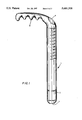
- the medullary template 11 is again an elongate tubular body having a bore 14 which is open at both its proximal and distal ends. And in the region of the distal end, two pairs of slots 12, 12' are seen at a longitudinal spacing ⁇ which will be understood to duplicate the standard spacing of transverse bores in the medullary nail (or in each nail of a series of medullary nails of differing length) to be selectively served by the template of FIGS. 2 and 3. Again, graduations of a longitudinal-measurement scale are viewable along the more proximal range of offsets from the distal end of the template body.
Abstract
Description
Claims (6)
Priority Applications (2)
| Application Number | Priority Date | Filing Date | Title |
|---|---|---|---|
| US08/318,671 US5681318A (en) | 1992-02-13 | 1994-10-12 | Medullary cavity template |
| CA 2138473 CA2138473C (en) | 1994-10-12 | 1994-12-19 | Medullary cavity template |
Applications Claiming Priority (7)
| Application Number | Priority Date | Filing Date | Title |
|---|---|---|---|
| DE9201811 | 1992-02-13 | ||
| DE9201811U | 1992-02-13 | ||
| DE9202174U DE9202174U1 (en) | 1992-02-13 | 1992-02-20 | |
| DE9202174ITX | 1992-02-20 | ||
| US13515593A | 1993-10-12 | 1993-10-12 | |
| ITVR930074A IT1262805B (en) | 1993-10-12 | 1993-10-12 | TEMPLATE FOR BONE MARROW CAVITY |
| US08/318,671 US5681318A (en) | 1992-02-13 | 1994-10-12 | Medullary cavity template |
Related Parent Applications (1)
| Application Number | Title | Priority Date | Filing Date |
|---|---|---|---|
| US13515593A Continuation-In-Part | 1992-02-13 | 1993-10-12 |
Publications (1)
| Publication Number | Publication Date |
|---|---|
| US5681318A true US5681318A (en) | 1997-10-28 |
Family
ID=27436445
Family Applications (1)
| Application Number | Title | Priority Date | Filing Date |
|---|---|---|---|
| US08/318,671 Expired - Fee Related US5681318A (en) | 1992-02-13 | 1994-10-12 | Medullary cavity template |
Country Status (1)
| Country | Link |
|---|---|
| US (1) | US5681318A (en) |
Cited By (35)
| Publication number | Priority date | Publication date | Assignee | Title |
|---|---|---|---|---|
| US5766179A (en) * | 1997-03-05 | 1998-06-16 | Orthofix S.R.L. | Mechanical system for blind nail-hole alignment of bone screws |
| US5989260A (en) * | 1994-08-22 | 1999-11-23 | Yao; Meei-Huei | Intramedullary nail guide rod with measure scale marked thereon |
| US5993451A (en) * | 1996-07-25 | 1999-11-30 | Arthrex, Inc. | Cannulated suture anchor drill guide |
| US6423061B1 (en) | 2000-03-14 | 2002-07-23 | Amei Technologies Inc. | High tibial osteotomy method and apparatus |
| US20030074005A1 (en) * | 2001-10-17 | 2003-04-17 | Roth Christoph A. | Orthopedic implant insertion instruments |
| US6678562B1 (en) | 2000-01-12 | 2004-01-13 | Amei Technologies Inc. | Combined tissue/bone growth stimulator and external fixation device |
| US6824384B1 (en) * | 1999-08-06 | 2004-11-30 | Guy Hure | Device for fixing a dental implant |
| US20050049602A1 (en) * | 2001-09-27 | 2005-03-03 | Matthias Honl | Surgical instruments |
| US20050107802A1 (en) * | 2003-11-19 | 2005-05-19 | Vanasse Thomas M. | Canal sizer and associated method |
| US20060064106A1 (en) * | 2004-09-23 | 2006-03-23 | Fernandez Alberto A | Coplanar X-ray guided aiming arm for locking of intramedullary nails |
| US7507240B2 (en) | 2005-03-18 | 2009-03-24 | Ron Anthon Olsen | Adjustable splint for osteosynthesis |
| US7713271B2 (en) | 2000-09-22 | 2010-05-11 | Piper Medical, Inc. | Intramedullary interlocking fixation devices for the distal radius |
| US7731738B2 (en) | 2005-12-09 | 2010-06-08 | Orthopro, Llc | Cannulated screw |
| US7846162B2 (en) | 2005-05-18 | 2010-12-07 | Sonoma Orthopedic Products, Inc. | Minimally invasive actuable bone fixation devices |
| US7909825B2 (en) | 2006-11-22 | 2011-03-22 | Sonoma Orthepedic Products, Inc. | Fracture fixation device, tools and methods |
| US8034056B2 (en) | 2004-07-15 | 2011-10-11 | Wright Medical Technology, Inc. | Guide assembly for intramedullary fixation and method of using the same |
| US8133231B2 (en) | 2004-07-06 | 2012-03-13 | Tyco Healthcare Group Lp | Instrument kit and method for performing meniscal repair |
| US20120109229A1 (en) * | 2009-07-10 | 2012-05-03 | Milux Holdind Sa | Hip joint instrument and method |
| US8287539B2 (en) | 2005-05-18 | 2012-10-16 | Sonoma Orthopedic Products, Inc. | Fracture fixation device, tools and methods |
| US8771283B2 (en) | 2007-12-17 | 2014-07-08 | Wright Medical Technology, Inc. | Guide assembly for intramedullary fixation and method of using the same |
| US8801755B2 (en) | 2004-04-06 | 2014-08-12 | Arthrex, Inc. | Suture anchor |
| US8821541B2 (en) | 1999-02-02 | 2014-09-02 | Arthrex, Inc. | Suture anchor with insert-molded rigid member |
| US8961516B2 (en) | 2005-05-18 | 2015-02-24 | Sonoma Orthopedic Products, Inc. | Straight intramedullary fracture fixation devices and methods |
| US9060820B2 (en) | 2005-05-18 | 2015-06-23 | Sonoma Orthopedic Products, Inc. | Segmented intramedullary fracture fixation devices and methods |
| USD739193S1 (en) * | 2013-03-15 | 2015-09-22 | Aesculap Implant Systems, Llc | Ratchet tool |
| US9155574B2 (en) | 2006-05-17 | 2015-10-13 | Sonoma Orthopedic Products, Inc. | Bone fixation device, tools and methods |
| US9179907B2 (en) | 2000-06-22 | 2015-11-10 | Arthrex, Inc. | Knotless graft fixation assembly |
| US9451971B2 (en) | 2004-07-15 | 2016-09-27 | Agilent Technologies, Inc. | Intramedullary fixation assembly and devices and methods for installing the same |
| US9521999B2 (en) | 2005-09-13 | 2016-12-20 | Arthrex, Inc. | Fully-threaded bioabsorbable suture anchor |
| US20170224377A1 (en) * | 2012-12-27 | 2017-08-10 | Pieter W.C.J. le Blanc | Surgical tunneler |
| US9770278B2 (en) | 2014-01-17 | 2017-09-26 | Arthrex, Inc. | Dual tip guide wire |
| US9814499B2 (en) | 2014-09-30 | 2017-11-14 | Arthrex, Inc. | Intramedullary fracture fixation devices and methods |
| US10478882B1 (en) * | 2017-05-02 | 2019-11-19 | Andrew Perez | Conduit marking device |
| US10874433B2 (en) | 2017-01-30 | 2020-12-29 | Stryker European Holdings I, Llc | Strut attachments for external fixation frame |
| US11426220B2 (en) | 2017-10-11 | 2022-08-30 | Howmedica Osteonics Corp. | Humeral fixation plate guides |
Citations (9)
| Publication number | Priority date | Publication date | Assignee | Title |
|---|---|---|---|---|
| US4337773A (en) * | 1980-10-20 | 1982-07-06 | Raftopoulos Demetrios D | Method of and device for placing a barrier in a cavity provided in a bone shaft |
| US4733654A (en) * | 1986-05-29 | 1988-03-29 | Marino James F | Intramedullar nailing assembly |
| US4800873A (en) * | 1987-08-31 | 1989-01-31 | Audell Robert A | Method for setting fractures |
| US4844064A (en) * | 1987-09-30 | 1989-07-04 | Baxter Travenol Laboratories, Inc. | Surgical cutting instrument with end and side openings |
| US4865025A (en) * | 1984-12-26 | 1989-09-12 | Carlo Buzzi | Drill guide aiming device for medullary rods |
| US5122146A (en) * | 1988-02-04 | 1992-06-16 | Pfizer Hospital Products Group, Inc. | Apparatus for reducing a fracture |
| US5171248A (en) * | 1991-02-27 | 1992-12-15 | Intermedics Orthopedics, Inc. | Medullary caliper |
| US5190548A (en) * | 1991-04-10 | 1993-03-02 | Linvatec Corporation | Surgical reamer |
| US5234434A (en) * | 1992-08-17 | 1993-08-10 | Marlowe Goble E | Mutliple guide sleeve drill guide |
-
1994
- 1994-10-12 US US08/318,671 patent/US5681318A/en not_active Expired - Fee Related
Patent Citations (9)
| Publication number | Priority date | Publication date | Assignee | Title |
|---|---|---|---|---|
| US4337773A (en) * | 1980-10-20 | 1982-07-06 | Raftopoulos Demetrios D | Method of and device for placing a barrier in a cavity provided in a bone shaft |
| US4865025A (en) * | 1984-12-26 | 1989-09-12 | Carlo Buzzi | Drill guide aiming device for medullary rods |
| US4733654A (en) * | 1986-05-29 | 1988-03-29 | Marino James F | Intramedullar nailing assembly |
| US4800873A (en) * | 1987-08-31 | 1989-01-31 | Audell Robert A | Method for setting fractures |
| US4844064A (en) * | 1987-09-30 | 1989-07-04 | Baxter Travenol Laboratories, Inc. | Surgical cutting instrument with end and side openings |
| US5122146A (en) * | 1988-02-04 | 1992-06-16 | Pfizer Hospital Products Group, Inc. | Apparatus for reducing a fracture |
| US5171248A (en) * | 1991-02-27 | 1992-12-15 | Intermedics Orthopedics, Inc. | Medullary caliper |
| US5190548A (en) * | 1991-04-10 | 1993-03-02 | Linvatec Corporation | Surgical reamer |
| US5234434A (en) * | 1992-08-17 | 1993-08-10 | Marlowe Goble E | Mutliple guide sleeve drill guide |
Non-Patent Citations (2)
| Title |
|---|
| Richards Manufacturing Company Brochure "New Hansen-Street Intramedullary Nail for the Femur" 1949, 1 page, Author Unknown. |
| Richards Manufacturing Company Brochure New Hansen Street Intramedullary Nail for the Femur 1949, 1 page, Author Unknown. * |
Cited By (70)
| Publication number | Priority date | Publication date | Assignee | Title |
|---|---|---|---|---|
| US5989260A (en) * | 1994-08-22 | 1999-11-23 | Yao; Meei-Huei | Intramedullary nail guide rod with measure scale marked thereon |
| US5993451A (en) * | 1996-07-25 | 1999-11-30 | Arthrex, Inc. | Cannulated suture anchor drill guide |
| US5766179A (en) * | 1997-03-05 | 1998-06-16 | Orthofix S.R.L. | Mechanical system for blind nail-hole alignment of bone screws |
| US6027506A (en) * | 1997-03-05 | 2000-02-22 | Orthofix, S.R.L. | Mechanical system for blind nail-hole alignment of bone screws |
| US8821541B2 (en) | 1999-02-02 | 2014-09-02 | Arthrex, Inc. | Suture anchor with insert-molded rigid member |
| US9526493B2 (en) | 1999-02-02 | 2016-12-27 | Arthrex, Inc. | Suture anchor with insert-molded rigid member |
| US9549726B2 (en) | 1999-02-02 | 2017-01-24 | Arthrex, Inc. | Suture anchor with insert-molded rigid member |
| US6824384B1 (en) * | 1999-08-06 | 2004-11-30 | Guy Hure | Device for fixing a dental implant |
| US6678562B1 (en) | 2000-01-12 | 2004-01-13 | Amei Technologies Inc. | Combined tissue/bone growth stimulator and external fixation device |
| US6423061B1 (en) | 2000-03-14 | 2002-07-23 | Amei Technologies Inc. | High tibial osteotomy method and apparatus |
| US20020164905A1 (en) * | 2000-03-14 | 2002-11-07 | Amei Technologies Inc., A Delaware Corporation | Osteotomy guide and method |
| US9706986B2 (en) | 2000-06-22 | 2017-07-18 | Arthrex, Inc. | Knotless suture and tissue securing method |
| US9775599B2 (en) | 2000-06-22 | 2017-10-03 | Arthrex, Inc. | Knotless tissue fixation assembly |
| US9179907B2 (en) | 2000-06-22 | 2015-11-10 | Arthrex, Inc. | Knotless graft fixation assembly |
| US10716556B2 (en) | 2000-06-22 | 2020-07-21 | Arthtrex, Inc. | Knotless tissue fixation assembly |
| US10052091B2 (en) | 2000-06-22 | 2018-08-21 | Arthrex, Inc. | Knotless suture or tissue fixation using an implant having a pointed tip |
| US10709436B2 (en) | 2000-06-22 | 2020-07-14 | Arthrex, Inc. | Graft fixation using a plug against suture |
| US8100910B2 (en) | 2000-09-22 | 2012-01-24 | Piper Medical, Inc. | Intramedullary interlocking fixation devices for the distal radius |
| US8092453B2 (en) | 2000-09-22 | 2012-01-10 | Piper Medical, Inc. | Intramedullary interlocking fixation devices for the distal radius |
| US7713271B2 (en) | 2000-09-22 | 2010-05-11 | Piper Medical, Inc. | Intramedullary interlocking fixation devices for the distal radius |
| US20050049602A1 (en) * | 2001-09-27 | 2005-03-03 | Matthias Honl | Surgical instruments |
| US7175633B2 (en) | 2001-10-17 | 2007-02-13 | Synthes (Usa) | Orthopedic implant insertion instruments |
| US20030074005A1 (en) * | 2001-10-17 | 2003-04-17 | Roth Christoph A. | Orthopedic implant insertion instruments |
| US8945131B2 (en) | 2003-11-19 | 2015-02-03 | DePuy Synthes Products, LLC | Canal sizer and associated method |
| US20100131022A1 (en) * | 2003-11-19 | 2010-05-27 | Depuy Products, Inc. | Canal sizer and associated method |
| US20050107802A1 (en) * | 2003-11-19 | 2005-05-19 | Vanasse Thomas M. | Canal sizer and associated method |
| US10537319B2 (en) | 2004-04-06 | 2020-01-21 | Arthrex, Inc. | Suture anchor |
| US9622739B2 (en) | 2004-04-06 | 2017-04-18 | Arthrex, Inc. | Suture anchor |
| US8801755B2 (en) | 2004-04-06 | 2014-08-12 | Arthrex, Inc. | Suture anchor |
| US8133231B2 (en) | 2004-07-06 | 2012-03-13 | Tyco Healthcare Group Lp | Instrument kit and method for performing meniscal repair |
| US9451971B2 (en) | 2004-07-15 | 2016-09-27 | Agilent Technologies, Inc. | Intramedullary fixation assembly and devices and methods for installing the same |
| US8034056B2 (en) | 2004-07-15 | 2011-10-11 | Wright Medical Technology, Inc. | Guide assembly for intramedullary fixation and method of using the same |
| US20060106400A1 (en) * | 2004-09-23 | 2006-05-18 | Alberto Fernandez | Coplanar X-ray guided aiming arm for locking of intramedullary nails |
| US7887545B2 (en) | 2004-09-23 | 2011-02-15 | Synthes Usa, Llc | Coplanar X-ray guided aiming arm for intramedullary nails |
| US20060064106A1 (en) * | 2004-09-23 | 2006-03-23 | Fernandez Alberto A | Coplanar X-ray guided aiming arm for locking of intramedullary nails |
| US10820916B2 (en) | 2004-09-23 | 2020-11-03 | DePuy Synthes Products, Inc. | Coplanar X-ray guided aiming arm for locking of intramedullary nails |
| US7481815B2 (en) | 2004-09-23 | 2009-01-27 | Synthes (U.S.A.) | Coplanar X-ray guided aiming arm for locking of intramedullary nails |
| US10080574B2 (en) | 2004-09-23 | 2018-09-25 | DePuy Synthes Products, Inc. | Coplana X-ray guided aiming arm for locking of intramedullary nails |
| US7507240B2 (en) | 2005-03-18 | 2009-03-24 | Ron Anthon Olsen | Adjustable splint for osteosynthesis |
| US7575575B2 (en) | 2005-03-18 | 2009-08-18 | Ron Anthon Olsen | Adjustable splint for osteosynthesis with modular components |
| US7588571B2 (en) | 2005-03-18 | 2009-09-15 | Ron Anthon Olsen | Adjustable splint for osteosynthesis with modular joint |
| US8961516B2 (en) | 2005-05-18 | 2015-02-24 | Sonoma Orthopedic Products, Inc. | Straight intramedullary fracture fixation devices and methods |
| US7846162B2 (en) | 2005-05-18 | 2010-12-07 | Sonoma Orthopedic Products, Inc. | Minimally invasive actuable bone fixation devices |
| US9060820B2 (en) | 2005-05-18 | 2015-06-23 | Sonoma Orthopedic Products, Inc. | Segmented intramedullary fracture fixation devices and methods |
| US8287541B2 (en) | 2005-05-18 | 2012-10-16 | Sonoma Orthopedic Products, Inc. | Fracture fixation device, tools and methods |
| US7914533B2 (en) | 2005-05-18 | 2011-03-29 | Sonoma Orthopedic Products, Inc. | Minimally invasive actuable bone fixation devices |
| US7942875B2 (en) | 2005-05-18 | 2011-05-17 | Sonoma Orthopedic Products, Inc. | Methods of using minimally invasive actuable bone fixation devices |
| US8287539B2 (en) | 2005-05-18 | 2012-10-16 | Sonoma Orthopedic Products, Inc. | Fracture fixation device, tools and methods |
| US10595847B2 (en) | 2005-09-13 | 2020-03-24 | Arthrex, Inc. | Fully-threaded bioabsorbable suture anchor |
| US9521999B2 (en) | 2005-09-13 | 2016-12-20 | Arthrex, Inc. | Fully-threaded bioabsorbable suture anchor |
| US11324493B2 (en) | 2005-09-13 | 2022-05-10 | Arthrex, Inc. | Fully-threaded bioabsorbable suture anchor |
| US7731738B2 (en) | 2005-12-09 | 2010-06-08 | Orthopro, Llc | Cannulated screw |
| US9155574B2 (en) | 2006-05-17 | 2015-10-13 | Sonoma Orthopedic Products, Inc. | Bone fixation device, tools and methods |
| US8439917B2 (en) | 2006-11-22 | 2013-05-14 | Sonoma Orthopedic Products, Inc. | Fracture fixation device, tools and methods |
| US7909825B2 (en) | 2006-11-22 | 2011-03-22 | Sonoma Orthepedic Products, Inc. | Fracture fixation device, tools and methods |
| US9259250B2 (en) | 2006-11-22 | 2016-02-16 | Sonoma Orthopedic Products, Inc. | Fracture fixation device, tools and methods |
| US9662153B2 (en) | 2007-12-17 | 2017-05-30 | Wright Medical Technology, Inc. | Guide assembly for intramedullary fixation and method of using the same |
| US8771283B2 (en) | 2007-12-17 | 2014-07-08 | Wright Medical Technology, Inc. | Guide assembly for intramedullary fixation and method of using the same |
| US9241720B2 (en) * | 2009-07-10 | 2016-01-26 | Peter Forsell | Hip joint instrument and method |
| US20120109229A1 (en) * | 2009-07-10 | 2012-05-03 | Milux Holdind Sa | Hip joint instrument and method |
| US20170224377A1 (en) * | 2012-12-27 | 2017-08-10 | Pieter W.C.J. le Blanc | Surgical tunneler |
| US10524830B2 (en) * | 2012-12-27 | 2020-01-07 | Tc1 Llc | Surgical tunneler |
| USD739193S1 (en) * | 2013-03-15 | 2015-09-22 | Aesculap Implant Systems, Llc | Ratchet tool |
| US9770278B2 (en) | 2014-01-17 | 2017-09-26 | Arthrex, Inc. | Dual tip guide wire |
| US9814499B2 (en) | 2014-09-30 | 2017-11-14 | Arthrex, Inc. | Intramedullary fracture fixation devices and methods |
| US10548648B2 (en) | 2014-09-30 | 2020-02-04 | Arthrex, Inc. | Intramedullary fracture fixation devices and methods |
| US10874433B2 (en) | 2017-01-30 | 2020-12-29 | Stryker European Holdings I, Llc | Strut attachments for external fixation frame |
| US11723690B2 (en) | 2017-01-30 | 2023-08-15 | Stryker European Operations Holdings Llc | Strut attachments for external fixation frame |
| US10478882B1 (en) * | 2017-05-02 | 2019-11-19 | Andrew Perez | Conduit marking device |
| US11426220B2 (en) | 2017-10-11 | 2022-08-30 | Howmedica Osteonics Corp. | Humeral fixation plate guides |
Similar Documents
| Publication | Publication Date | Title |
|---|---|---|
| US5681318A (en) | Medullary cavity template | |
| EP0984840B1 (en) | Drilling guide and measuring instrumentation | |
| US5207753A (en) | Bone fracture repair apparatus and method | |
| US4622959A (en) | Multi-use femoral intramedullary nail | |
| JP3180223B2 (en) | Device for mechanically aligning a bone screw in an intramedullary nail member | |
| US5122146A (en) | Apparatus for reducing a fracture | |
| EP0957782B1 (en) | Drill guide instrument | |
| US6524318B1 (en) | Spinal surgery instruments and methods | |
| US5890897A (en) | Adjustable length drills | |
| CA1175722A (en) | Method and system for inserting a surgical wire | |
| US5766179A (en) | Mechanical system for blind nail-hole alignment of bone screws | |
| US6824384B1 (en) | Device for fixing a dental implant | |
| EP2008585B1 (en) | Measuring device for measuring a length of a through-hole in a bone | |
| US20020058949A1 (en) | Device for identifying the position of intramedullary nail securement screw holes | |
| US5989260A (en) | Intramedullary nail guide rod with measure scale marked thereon | |
| AU2008200892B2 (en) | Apparatus for indicating the bone thickness between a cavity in a bone and the bone surface | |
| CA2138473C (en) | Medullary cavity template | |
| US7060070B1 (en) | Locking nail and aim-taking apparatus | |
| CA2115411A1 (en) | Medullary cavity template | |
| KR100311781B1 (en) | Gauge for the medullary cavity | |
| US20230024165A1 (en) | Cannulated implant delivery device with adjustable insertion depth | |
| JPH0649903U (en) | Depth gauge | |
| KR20200017198A (en) | Measurement device for bone cutting depth |
Legal Events
| Date | Code | Title | Description |
|---|---|---|---|
| AS | Assignment |
Owner name: ORTHOFIX S.R.L., ITALY Free format text: ASSIGNMENT OF ASSIGNORS INTEREST;ASSIGNORS:FACCIOLI, GIOVANNI;ROSSI, STEFANO;REEL/FRAME:007346/0312 Effective date: 19941006 |
|
| AS | Assignment |
Owner name: ORTHOFIX S.R.L., ITALY Free format text: ASSIGNMENT OF ASSIGNORS INTEREST;ASSIGNOR:PENNIG, DIETMAR;REEL/FRAME:007520/0659 Effective date: 19950612 |
|
| FEPP | Fee payment procedure |
Free format text: PAYOR NUMBER ASSIGNED (ORIGINAL EVENT CODE: ASPN); ENTITY STATUS OF PATENT OWNER: LARGE ENTITY |
|
| FEPP | Fee payment procedure |
Free format text: PAT HLDR NO LONGER CLAIMS SMALL ENT STAT AS SMALL BUSINESS (ORIGINAL EVENT CODE: LSM2); ENTITY STATUS OF PATENT OWNER: LARGE ENTITY |
|
| FPAY | Fee payment |
Year of fee payment: 4 |
|
| AS | Assignment |
Owner name: ORTHOFIX INTERNATIONAL B.V., NETHERLANDS Free format text: ASSIGNMENT OF ASSIGNORS INTEREST;ASSIGNOR:ORTHOFIX S.R.L.;REEL/FRAME:014446/0135 Effective date: 20030101 |
|
| LAPS | Lapse for failure to pay maintenance fees | ||
| STCH | Information on status: patent discontinuation |
Free format text: PATENT EXPIRED DUE TO NONPAYMENT OF MAINTENANCE FEES UNDER 37 CFR 1.362 |
|
| FP | Lapsed due to failure to pay maintenance fee |
Effective date: 20051028 |