US5630421A - Ultrasound imaging - Google Patents
Ultrasound imaging Download PDFInfo
- Publication number
- US5630421A US5630421A US08/573,062 US57306295A US5630421A US 5630421 A US5630421 A US 5630421A US 57306295 A US57306295 A US 57306295A US 5630421 A US5630421 A US 5630421A
- Authority
- US
- United States
- Prior art keywords
- data
- pipeline
- processing
- store
- display
- Prior art date
- Legal status (The legal status is an assumption and is not a legal conclusion. Google has not performed a legal analysis and makes no representation as to the accuracy of the status listed.)
- Expired - Lifetime
Links
Images


Classifications
-
- G—PHYSICS
- G01—MEASURING; TESTING
- G01S—RADIO DIRECTION-FINDING; RADIO NAVIGATION; DETERMINING DISTANCE OR VELOCITY BY USE OF RADIO WAVES; LOCATING OR PRESENCE-DETECTING BY USE OF THE REFLECTION OR RERADIATION OF RADIO WAVES; ANALOGOUS ARRANGEMENTS USING OTHER WAVES
- G01S7/00—Details of systems according to groups G01S13/00, G01S15/00, G01S17/00
- G01S7/52—Details of systems according to groups G01S13/00, G01S15/00, G01S17/00 of systems according to group G01S15/00
- G01S7/52017—Details of systems according to groups G01S13/00, G01S15/00, G01S17/00 of systems according to group G01S15/00 particularly adapted to short-range imaging
- G01S7/52023—Details of receivers
- G01S7/52025—Details of receivers for pulse systems
- G01S7/52026—Extracting wanted echo signals
-
- G—PHYSICS
- G01—MEASURING; TESTING
- G01S—RADIO DIRECTION-FINDING; RADIO NAVIGATION; DETERMINING DISTANCE OR VELOCITY BY USE OF RADIO WAVES; LOCATING OR PRESENCE-DETECTING BY USE OF THE REFLECTION OR RERADIATION OF RADIO WAVES; ANALOGOUS ARRANGEMENTS USING OTHER WAVES
- G01S7/00—Details of systems according to groups G01S13/00, G01S15/00, G01S17/00
- G01S7/52—Details of systems according to groups G01S13/00, G01S15/00, G01S17/00 of systems according to group G01S15/00
- G01S7/523—Details of pulse systems
- G01S7/526—Receivers
- G01S7/53—Means for transforming coordinates or for evaluating data, e.g. using computers
-
- G—PHYSICS
- G10—MUSICAL INSTRUMENTS; ACOUSTICS
- G10K—SOUND-PRODUCING DEVICES; METHODS OR DEVICES FOR PROTECTING AGAINST, OR FOR DAMPING, NOISE OR OTHER ACOUSTIC WAVES IN GENERAL; ACOUSTICS NOT OTHERWISE PROVIDED FOR
- G10K11/00—Methods or devices for transmitting, conducting or directing sound in general; Methods or devices for protecting against, or for damping, noise or other acoustic waves in general
- G10K11/18—Methods or devices for transmitting, conducting or directing sound
- G10K11/26—Sound-focusing or directing, e.g. scanning
- G10K11/34—Sound-focusing or directing, e.g. scanning using electrical steering of transducer arrays, e.g. beam steering
- G10K11/341—Circuits therefor
-
- G—PHYSICS
- G01—MEASURING; TESTING
- G01S—RADIO DIRECTION-FINDING; RADIO NAVIGATION; DETERMINING DISTANCE OR VELOCITY BY USE OF RADIO WAVES; LOCATING OR PRESENCE-DETECTING BY USE OF THE REFLECTION OR RERADIATION OF RADIO WAVES; ANALOGOUS ARRANGEMENTS USING OTHER WAVES
- G01S15/00—Systems using the reflection or reradiation of acoustic waves, e.g. sonar systems
- G01S15/88—Sonar systems specially adapted for specific applications
- G01S15/89—Sonar systems specially adapted for specific applications for mapping or imaging
- G01S15/8906—Short-range imaging systems; Acoustic microscope systems using pulse-echo techniques
- G01S15/8909—Short-range imaging systems; Acoustic microscope systems using pulse-echo techniques using a static transducer configuration
- G01S15/8915—Short-range imaging systems; Acoustic microscope systems using pulse-echo techniques using a static transducer configuration using a transducer array
-
- G—PHYSICS
- G01—MEASURING; TESTING
- G01S—RADIO DIRECTION-FINDING; RADIO NAVIGATION; DETERMINING DISTANCE OR VELOCITY BY USE OF RADIO WAVES; LOCATING OR PRESENCE-DETECTING BY USE OF THE REFLECTION OR RERADIATION OF RADIO WAVES; ANALOGOUS ARRANGEMENTS USING OTHER WAVES
- G01S7/00—Details of systems according to groups G01S13/00, G01S15/00, G01S17/00
- G01S7/52—Details of systems according to groups G01S13/00, G01S15/00, G01S17/00 of systems according to group G01S15/00
- G01S7/52017—Details of systems according to groups G01S13/00, G01S15/00, G01S17/00 of systems according to group G01S15/00 particularly adapted to short-range imaging
- G01S7/52053—Display arrangements
- G01S7/52057—Cathode ray tube displays
- G01S7/52058—Cathode ray tube displays displaying one measured variable; A-scan display
-
- G—PHYSICS
- G01—MEASURING; TESTING
- G01S—RADIO DIRECTION-FINDING; RADIO NAVIGATION; DETERMINING DISTANCE OR VELOCITY BY USE OF RADIO WAVES; LOCATING OR PRESENCE-DETECTING BY USE OF THE REFLECTION OR RERADIATION OF RADIO WAVES; ANALOGOUS ARRANGEMENTS USING OTHER WAVES
- G01S7/00—Details of systems according to groups G01S13/00, G01S15/00, G01S17/00
- G01S7/52—Details of systems according to groups G01S13/00, G01S15/00, G01S17/00 of systems according to group G01S15/00
- G01S7/52017—Details of systems according to groups G01S13/00, G01S15/00, G01S17/00 of systems according to group G01S15/00 particularly adapted to short-range imaging
- G01S7/52079—Constructional features
- G01S7/52082—Constructional features involving a modular construction, e.g. a computer with short range imaging equipment
Definitions
- the present invention relates to ultrasound imaging and more particularly to an intravascular ultrasound imaging system, an example of which is disclosed in our UK pending Application 2,268,806.
- an ultrasonic transceiver consisting of an ultrasound transmitter circuit that can be programmed to vary the order in which the elements are excited and to vary the excitation pulse and an ultrasound receive circuit that converts the ultrasound echo signal into digital form.
- a high powered computer processes the ultrasound echoes, performs focusing, demodulates, converts to rectangular format and displays the data as a real time B-mode image.
- the present invention is concerned with this problem and with providing an easily used and rapid arrangement for replaying such ultrasound images and at the same time improving the quality of the reproduced images.
- the image data is processed in a pipeline which allows a variety of methods for the software processing of the ultrasound echo signals.
- a pipeline process the processing stages are divided into serial tasks, so that the result of one process is fed to the next. This has the advantage that it allows sharing of processors and thus a degree of parallel processing to take place.
- the present invention is by way of an enhancement or improvement of such a system to provide the playback feature referred to earlier.
- an intravascular ultrasound imaging system has the following combination of features:
- a transducer array mounted on the distal end of a catheter and electrically connected to a transceiver at the proximal end of the catheter;
- the transceiver includes means for converting analogue echo signals generated by the ultrasound transducer into digital signals and means for processing those digital signals in a pipeline to produce a real-time image on a display;
- the pipeline consists of a number of data processing stages, and the data set varies in size at different points in the pipeline, and includes means to divert/extract the data at a convenient point in the pipeline from the pipeline and store it in a dedicated memory;
- the pipeline includes means to divert/extract the data from the pipeline and to store it in the memory;
- (e) means to recall the stored data and reintroduce it into the pipeline at the same point that it was removed to retrospectively display the stored image.
- FIG. 1 is a block diagram illustrating an intravascular ultrasound imaging system to which the present invention can be applied;
- FIG. 2 shows how the software of FIG. 1 communicates with external peripheral equipment etc;
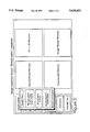
- FIG. 3 illustrates the data processing pipeline from transducer array to image display
- FIG. 4 is a state machine illustrating the B-mode image sequence operation
- FIG. 5 is a diagrammatic representation of the display screen and associated control.
- FIG. 6 is an enlarged view of the B-mode sequence control panel shown in FIG. 5.
- FIG. 1 A first figure.
- An ultrasonic transducer array 2 is mounted on the distal end of a catheter 1 and is adapted to be inserted into an organ, e.g., artery 3 of a patient in known manner.
- the proximal end of the catheter 4 is connected to a transceiver arrangement shown to the right of the dotted line in FIG. 1.
- a multiplexer/demultiplexer arrangement 5 is provided.
- the transducer array 2 is energised by an ultrasonic driving circuit 6 and signals representative of echo pulses received by the transducer array 2 are received by an ultrasonic receiving circuit 7.
- the analogue signals received by the circuit 7 are then converted into digital signals by an analogue-to-digital converter 8 and then passed via a fast-in-fast-out store 9 to a computer/processor 10 which is under stored program control by means of software 11.
- Images representative of the interior of the artery 3 can be displayed on high resolution graphics terminal 12 or printed out by a printer 13.
- FIG. 1 is merely to illustrate the kind of intravascular ultrasonic imaging system to which the present invention may be applied.
- FIG. 2 shows in more detail the structure of the software 11 of FIG. 1. It consists of a processing pipeline 17, which processes the ultrasound data to give an ultrasound image, a B-mode display process 18, which manages the display of that data, and controls contrast and brightness, and communicates with the display window server 19, which incorporates industry standard display routines such as X-windows. Both the processing pipeline and the B-mode display process are managed by the acquisition control 20, which synchronises the processes and is controlled from the WIMP based human interface 21. The human interface also manages other processes such as image manipulation 22 which is not described in this specification, and it communicates with the database system 23, which manages data handling and file management, including data stored on the storage device 24.
- the pipeline 17 is shown in more detail in FIG. 3 together with a sequence control 14.
- the pipeline allows sharing of processors in a multi-process or architecture, and thus can accommodate parallel processing.
- FIG. 3 shows the preferred embodiment of this pipeline in which the ultrasound data is focused to give a number of radial A-scans, and then converted to an X-Y display.
- the focusing process is described in our co-pending UK application 9418630.
- the amount of data for each frame at different stages throughout the pipeline is shown in FIG. 3 for a typical set of parameters and at the focused A-scan stage the data is at its minimum size of 20 kbytes having been at 40 kbytes at the raw ultrasound data stage.
- the computer system used to process the real-time B-mode images referred to above has sufficient electronic memory 1 to store this partially processed data frame by frame.
- the memory is a buffer memory in the sequence control 14.
- This data can then be transferred to an appropriate non-volatile magnetic or opto-magnetic storage media 15 as digital computer compatible files.
- the sequence control process can transfer this data to storage while new data is being acquired, thus limiting the requirements on the buffer size.
- one buffer is being filled with new data, whilst a second buffer is being transferred to storage, and the two buffers alternate their function.
- This data can be later recalled from storage 15 and re-introduced into the processing pipeline at the same point P at which it was removed, and the processing continued until the final image is displayed at 12.
- the later stage processing will typically increase the amount of data as it is converted into a rectilinear image. Since there is no data lost, the net effect is as if the final video image had been stored, but using significantly less data and hence data storage.
- the control of the storage and retrieval is performed by a screen-based user interface 16, and since the delay in passing through the pipeline is of the order of the frame-to-frame interval, ie. 1/20 second, the effect of varying the controls appears to be instantaneous.
- FIGS. 1 to 4 illustrate how the system operates.
- FIG. 5 illustrates how the screen based controls are positioned on the display 12, adjacent to the displayed image.
- FIG. 6 is an enlarged more detailed view of the B-mode sequence control panel shown in FIG. 5, demonstrating how the screen layout can be designed to present the user with a control panel that is familiar to users of conventional tape VCRs.
Abstract
Description
Claims (16)
Applications Claiming Priority (2)
| Application Number | Priority Date | Filing Date | Title |
|---|---|---|---|
| GB9426191A GB2296565B (en) | 1994-12-23 | 1994-12-23 | Ultrasound imaging |
| GB9426191 | 1994-12-23 |
Publications (1)
| Publication Number | Publication Date |
|---|---|
| US5630421A true US5630421A (en) | 1997-05-20 |
Family
ID=10766565
Family Applications (1)
| Application Number | Title | Priority Date | Filing Date |
|---|---|---|---|
| US08/573,062 Expired - Lifetime US5630421A (en) | 1994-12-23 | 1995-12-15 | Ultrasound imaging |
Country Status (2)
| Country | Link |
|---|---|
| US (1) | US5630421A (en) |
| GB (1) | GB2296565B (en) |
Cited By (12)
| Publication number | Priority date | Publication date | Assignee | Title |
|---|---|---|---|---|
| US5924993A (en) * | 1997-10-15 | 1999-07-20 | Advanced Coronary Intervention, Inc. | Intravascular ultrasound mixed signal multiplexer/pre-amplifier asic |
| US5947905A (en) * | 1997-10-15 | 1999-09-07 | Advanced Coronary Intervention, Inc. | Ultrasound transducer array probe for intraluminal imaging catheter |
| US6106468A (en) * | 1999-04-05 | 2000-08-22 | Agilent Technologies, Inc. | Ultrasound system employing a unified memory |
| US6300961B1 (en) * | 1997-12-31 | 2001-10-09 | Acuson Corporation | Ultrasonic system and method for processing data |
| US6358204B1 (en) | 1997-12-31 | 2002-03-19 | Acuson Corporation | Ultrasonic system and method for storing data |
| US20050188180A1 (en) * | 2004-01-12 | 2005-08-25 | Joerg Illmann | Dynamic control of computer resources for the pipeline processing of data using anytime algorithms |
| US20060126108A1 (en) * | 2004-12-15 | 2006-06-15 | Lexmark International, Inc. | Method, printer, and storage medium for printing a medical image |
| US20080030501A1 (en) * | 2006-08-02 | 2008-02-07 | General Electric Company | System and methods for rule-based volume rendition and navigation |
| US20090018443A1 (en) * | 2007-07-12 | 2009-01-15 | Colby Brian V | System for generating multiple beams from a single receive event |
| US20100305442A1 (en) * | 2009-05-29 | 2010-12-02 | Boston Scientific Scimed, Inc. | Systems and methods for implementing a data management system for catheter-based imaging systems |
| US20130024498A1 (en) * | 2011-07-19 | 2013-01-24 | Siemens Aktiengesellschaft | Simulating the performance of medical-engineering procedures in a client-server environment |
| CN114026417A (en) * | 2019-06-25 | 2022-02-08 | 布弗莱运营公司 | Method and apparatus for processing ultrasound signals |
Families Citing this family (1)
| Publication number | Priority date | Publication date | Assignee | Title |
|---|---|---|---|---|
| US6095976A (en) * | 1997-06-19 | 2000-08-01 | Medinol Ltd. | Method for enhancing an image derived from reflected ultrasound signals produced by an ultrasound transmitter and detector inserted in a bodily lumen |
Citations (6)
| Publication number | Priority date | Publication date | Assignee | Title |
|---|---|---|---|---|
| US5081993A (en) * | 1987-11-11 | 1992-01-21 | Circulation Research Limited | Methods and apparatus for the examination and treatment of internal organs |
| GB2268806A (en) * | 1992-07-14 | 1994-01-19 | Intravascular Res Ltd | Methods and apparatus for the examination and treatment of internal organs |
| US5322066A (en) * | 1992-05-22 | 1994-06-21 | Shimadzu Corporation | Discretely modifiable imaging in ultrasonic diagnostic equipment |
| US5377682A (en) * | 1991-09-05 | 1995-01-03 | Matsushita Electric Industrial Co., Ltd. | Ultrasonic probe for transmission and reception of ultrasonic wave and ultrasonic diagnostic apparatus including ultrasonic probe |
| US5421338A (en) * | 1988-03-21 | 1995-06-06 | Boston Scientific Corporation | Acoustic imaging catheter and the like |
| US5453575A (en) * | 1993-02-01 | 1995-09-26 | Endosonics Corporation | Apparatus and method for detecting blood flow in intravascular ultrasonic imaging |
-
1994
- 1994-12-23 GB GB9426191A patent/GB2296565B/en not_active Expired - Fee Related
-
1995
- 1995-12-15 US US08/573,062 patent/US5630421A/en not_active Expired - Lifetime
Patent Citations (6)
| Publication number | Priority date | Publication date | Assignee | Title |
|---|---|---|---|---|
| US5081993A (en) * | 1987-11-11 | 1992-01-21 | Circulation Research Limited | Methods and apparatus for the examination and treatment of internal organs |
| US5421338A (en) * | 1988-03-21 | 1995-06-06 | Boston Scientific Corporation | Acoustic imaging catheter and the like |
| US5377682A (en) * | 1991-09-05 | 1995-01-03 | Matsushita Electric Industrial Co., Ltd. | Ultrasonic probe for transmission and reception of ultrasonic wave and ultrasonic diagnostic apparatus including ultrasonic probe |
| US5322066A (en) * | 1992-05-22 | 1994-06-21 | Shimadzu Corporation | Discretely modifiable imaging in ultrasonic diagnostic equipment |
| GB2268806A (en) * | 1992-07-14 | 1994-01-19 | Intravascular Res Ltd | Methods and apparatus for the examination and treatment of internal organs |
| US5453575A (en) * | 1993-02-01 | 1995-09-26 | Endosonics Corporation | Apparatus and method for detecting blood flow in intravascular ultrasonic imaging |
Cited By (17)
| Publication number | Priority date | Publication date | Assignee | Title |
|---|---|---|---|---|
| US5947905A (en) * | 1997-10-15 | 1999-09-07 | Advanced Coronary Intervention, Inc. | Ultrasound transducer array probe for intraluminal imaging catheter |
| US5924993A (en) * | 1997-10-15 | 1999-07-20 | Advanced Coronary Intervention, Inc. | Intravascular ultrasound mixed signal multiplexer/pre-amplifier asic |
| US6300961B1 (en) * | 1997-12-31 | 2001-10-09 | Acuson Corporation | Ultrasonic system and method for processing data |
| US6358204B1 (en) | 1997-12-31 | 2002-03-19 | Acuson Corporation | Ultrasonic system and method for storing data |
| US6417857B2 (en) | 1997-12-31 | 2002-07-09 | Acuson Corporation | System architecture and method for operating a medical diagnostic ultrasound system |
| US6106468A (en) * | 1999-04-05 | 2000-08-22 | Agilent Technologies, Inc. | Ultrasound system employing a unified memory |
| US8161486B2 (en) * | 2004-01-12 | 2012-04-17 | Siemens Aktiengesellschaft | Dynamic control of computer resources for the pipeline processing of data using anytime algorithms |
| US20050188180A1 (en) * | 2004-01-12 | 2005-08-25 | Joerg Illmann | Dynamic control of computer resources for the pipeline processing of data using anytime algorithms |
| US20060126108A1 (en) * | 2004-12-15 | 2006-06-15 | Lexmark International, Inc. | Method, printer, and storage medium for printing a medical image |
| US20080030501A1 (en) * | 2006-08-02 | 2008-02-07 | General Electric Company | System and methods for rule-based volume rendition and navigation |
| US8179396B2 (en) * | 2006-08-02 | 2012-05-15 | General Electric Company | System and methods for rule-based volume rendition and navigation |
| US20090018443A1 (en) * | 2007-07-12 | 2009-01-15 | Colby Brian V | System for generating multiple beams from a single receive event |
| US8690782B2 (en) * | 2007-07-12 | 2014-04-08 | Siemens Medical Solutions Usa, Inc. | System for generating multiple beams from a single receive event |
| US20100305442A1 (en) * | 2009-05-29 | 2010-12-02 | Boston Scientific Scimed, Inc. | Systems and methods for implementing a data management system for catheter-based imaging systems |
| US20130024498A1 (en) * | 2011-07-19 | 2013-01-24 | Siemens Aktiengesellschaft | Simulating the performance of medical-engineering procedures in a client-server environment |
| US9286124B2 (en) * | 2011-07-19 | 2016-03-15 | Siemens Aktiengesellschaft | Simulating the performance of medical-engineering procedures in a client-server environment |
| CN114026417A (en) * | 2019-06-25 | 2022-02-08 | 布弗莱运营公司 | Method and apparatus for processing ultrasound signals |
Also Published As
| Publication number | Publication date |
|---|---|
| GB2296565B (en) | 1999-06-16 |
| GB2296565A (en) | 1996-07-03 |
| GB9426191D0 (en) | 1995-02-22 |
Similar Documents
| Publication | Publication Date | Title |
|---|---|---|
| US6231508B1 (en) | Ultrasonic diagnostic imaging system with digital video image marking | |
| US6231510B1 (en) | Ultrasonic diagnostic imaging system | |
| US5630421A (en) | Ultrasound imaging | |
| US6213944B1 (en) | Ultrasonic diagnostic imaging system with a digital video recorder with visual controls | |
| EP0241261A2 (en) | Improvements in or relating to video editing and processing systems | |
| JPH0385147A (en) | Ultrasonic diagnosis apparatus | |
| JP4003980B2 (en) | Image recording device | |
| JPS59158685A (en) | Still picture reproducing device | |
| WO2003007604A2 (en) | A method and apparatus for performing real-time storage of ultrasound video image information | |
| US4409617A (en) | Information processing | |
| JPH01189772A (en) | Image filing device | |
| US4412249A (en) | Ultrasonic image storage device and method | |
| EP0083985B1 (en) | Improved ultrasonic image storage system | |
| JPS6472729A (en) | Image diagnostic apparatus | |
| CN1608590B (en) | Data recording system | |
| JPH02203845A (en) | Ultrasonic wave diagnostic device | |
| JPS63189130A (en) | Medical image recording apparatus | |
| Vogel et al. | Processing equipment for two-dimensional echocardiographic data | |
| GB2090502A (en) | Rendering video signals compatible with recorder or display | |
| JP3268775B2 (en) | Medical digital image storage and playback device | |
| JPH11206762A (en) | Ultrasonic diagnostic system | |
| JP2888583B2 (en) | Ultrasound diagnostic equipment | |
| JPH05168627A (en) | Ultrasonic diagnostic system | |
| JP2602434B2 (en) | Ultrasound diagnostic equipment | |
| JPS6012041A (en) | Ultrasonic diagnostic apparatus |
Legal Events
| Date | Code | Title | Description |
|---|---|---|---|
| STCF | Information on status: patent grant |
Free format text: PATENTED CASE |
|
| FEPP | Fee payment procedure |
Free format text: PAYOR NUMBER ASSIGNED (ORIGINAL EVENT CODE: ASPN); ENTITY STATUS OF PATENT OWNER: SMALL ENTITY Free format text: PAT HLDR NO LONGER CLAIMS SMALL ENT STAT AS INDIV INVENTOR (ORIGINAL EVENT CODE: LSM1); ENTITY STATUS OF PATENT OWNER: SMALL ENTITY |
|
| FPAY | Fee payment |
Year of fee payment: 4 |
|
| FEPP | Fee payment procedure |
Free format text: PAT HOLDER CLAIMS SMALL ENTITY STATUS, ENTITY STATUS SET TO SMALL (ORIGINAL EVENT CODE: LTOS); ENTITY STATUS OF PATENT OWNER: SMALL ENTITY |
|
| FPAY | Fee payment |
Year of fee payment: 8 |
|
| FPAY | Fee payment |
Year of fee payment: 12 |
|
| REMI | Maintenance fee reminder mailed |