US5601603A - Use of and process for the introduction of fibrin sealant into a puncture channel - Google Patents
Use of and process for the introduction of fibrin sealant into a puncture channel Download PDFInfo
- Publication number
- US5601603A US5601603A US08/387,728 US38772895A US5601603A US 5601603 A US5601603 A US 5601603A US 38772895 A US38772895 A US 38772895A US 5601603 A US5601603 A US 5601603A
- Authority
- US
- United States
- Prior art keywords
- cannula
- sealing
- accordance
- working
- sealing cannula
- Prior art date
- Legal status (The legal status is an assumption and is not a legal conclusion. Google has not performed a legal analysis and makes no representation as to the accuracy of the status listed.)
- Expired - Lifetime
Links
Images


Classifications
-
- A—HUMAN NECESSITIES
- A61—MEDICAL OR VETERINARY SCIENCE; HYGIENE
- A61B—DIAGNOSIS; SURGERY; IDENTIFICATION
- A61B17/00—Surgical instruments, devices or methods, e.g. tourniquets
- A61B17/0057—Implements for plugging an opening in the wall of a hollow or tubular organ, e.g. for sealing a vessel puncture or closing a cardiac septal defect
Definitions
- This invention relates to the use of endogenous blood coagulants obtained from plasma protein in the form of a two-component fibrin sealant, said components being mixed at the instant they are delivered.
- This invention also relates to a device for introducing the two-component fibrin sealant into a puncture channel in the vicinity of an arterial or venous puncture point.
- a device in accordance with one embodiment of this invention comprising a sealing cannula through which a work cannula passes axially from top to bottom, wherein the work cannula which is used for the intravascular introduction of an instrument into a vessel is surrounded at a distance by the sealing cannula, so that the fibrin sealant is conducted between the sealing cannula and the work cannula from a connector to at least one radially oriented outlet opening in the sealing cannula.
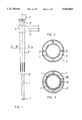
- FIG. 1 is a side view of the device in accordance with one embodiment of this invention.
- FIG. 2 is a cross sectional view through the device of FIG. 1 along the line II--II on an enlarged scale;
- FIG. 3 is a longitudinal cross sectional view of the device shown in FIG. 1;
- FIG. 4 is an enlarged cross sectional view of the connector area of the device in accordance with one embodiment of this invention.
- FIG. 5 is an enlarged longitudinal cross sectional view of the exit area of the working cannula from the sealing cannula in accordance with one embodiment of this invention
- FIG. 6 shows a side view of a second embodiment of the device of this invention.
- FIG. 7 is a cross sectional view through the device of FIG. 6 along the line VII--VII;
- FIG. 8 is a longitudinal cross sectional view through the device of FIG. 6;
- FIG. 9 is an enlarged cross sectional view of the connector area of the device shown in FIG. 8.
- FIG. 10 is a cross sectional view of the exit of the working cannula from the sealing cannula.
- the embodiment of the device of this invention in accordance with FIGS. 1 to 5 comprises only three elements which can be put together.
- the working cannula also called worksheath in technical language, is identified by the reference numeral 1.
- the working cannula itself is a small cylindrical tube, open at both ends, made of plastic. Its front end 1' is used for introducing the cannula through the puncture point into the opened blood vessel.
- the working cannula is relatively thin-walled and therefore has a certain amount of bending flexibility.
- the working cannula 1 is fixedly connected to a medical coupling 3 at the other end, the rear end.
- the actual medical coupling 3 can be a known Luer locking coupling, for example.
- An exactly fashioned muff 3' is formed in an interlocking and sealing manner on the actual medical coupling 3.
- the working cannula 1 axially extends in the longitudinal direction through a sealing cannula 2 and, at the front end, projects for some distance out of the sealing cannula.
- the sealing cannula 2 itself is also embodied as a small concentric tube, but its exterior diameter, and preferably also its interior diameter, decrease from the top end to the bottom end, that is, the interior diameter is reduced from the top end where the medical coupling 3 is inserted to the bottom end where the working cannula 1 emerges from the sealing cannula 2.
- a hollow space 7 is formed between the working cannula 1 and the sealing cannula 2 over the entire length where the working cannula 1 is concentrically enclosed by the sealing cannula 2.
- the sealing cannula 2 has a reinforced cuff 4 at the top end which has a considerably greater wall thickness than the wall thickness of the sealing cannula 2.
- a connector 5 terminates in the sealing cannula 2 in the area of the reinforced cuff 4.
- a two-component fibrin sealant (F) is introduced into the hollow space between the working cannula 1 and the sealing cannula 2 through this connector 5. The fibrin sealant exits from the hollow space 7 only through the at least one outlet opening 6 in the lower area of the sealing cannula 2.
- the at least one outlet opening 6 is at least approximately radially oriented toward the outside.
- radially not only the direction, interpreted in a strictly geometric sense, is meant. Rather this is only intended to express that the outflow direction is not axial.
- the functioning of the device is assured by a single outlet opening, but preferably several outlet openings 6 distributed over the circumference may be provided.
- the form of the embodiment of the outlet openings 6 can be freely designed. However, for technical production reasons, they are preferably formed in the shape of several linear slits distributed over the circumference.
- the upper opening of the sealing cannula 2 must be provided with a snug fit.
- annular sealing bead or sealing rib 11 For sealing the working cannula 1 against the sealing cannula 2 in the area of the through-opening 10, an annular sealing bead or sealing rib 11, which is oriented radially inward and sealingly rests on the outer surface of the working cannula 1, is disposed in the through-opening 10.
- the connector 5 is formed in one piece directly on the sealing cannula 2 in the area of the reinforced cuff. It is, however, possible to manufacture the connector separately and to connect it later with the sealing cannula by a screw connection 17. In place of the screw connection 17, a welded or adhesive connection is also possible. Mixing elements are already available on the market for mixing the two components of the two-component fibrin sealant. Therefore, for reasons of cost, the connector 5 should be sized such that an already available mixing element 13 can be inserted into it.
- the wall thickness of the working cannula 1 is very little. Preferably, it is only a few tenths of a millimeter.
- the hollow space 7 remaining concentrically around the working cannula 1 between its outer wall and the inner wall of the sealing cannula 2 is of extremely small dimensions. Because all of the surgical instruments must be inserted and removed though the working cannula 1, it is preferred to provide means which enable the hollow space 7 to remain continuously open. Support ribs 9 which preferably extend axially are disposed on the inner wall of the sealing cannula 2 for this purpose.
- FIGS. 6 to 10 A second preferred embodiment of the device of this invention for introducing two-component fibrin sealant through a puncture channel into the vicinity of an arterial or venous puncture point is shown in FIGS. 6 to 10.
- the working cannula 1 with the associated medical coupling 3 must be exactly adapted to the sealing cannula for a sealing connection
- a commercially available working cannula with an arbitrary medical coupling 3 can be used.
- a sealing connection between the medical coupling 3 and the sealing cannula 2 not required.
- the working cannula 1 completely extends in the axial direction through the sealing cannula 2.
- the medical coupling 3 fixedly disposed on the working cannula 1 does not enter the sealing cannula 2, but is located shortly above it.
- the lower end of the working cannula 1' again is embodied as conical.
- the sealing cannula 2 again has a reinforced cuff 4 at its upper end.
- a connector 5 terminates in the interior of the sealing cannula 2 in the area of the reinforced cuff 4.
- the sealing cannula 2 also has an outlet opening 6 directed approximately radially outward.
- several outlet openings 6 are disposed evenly distributed over the circumference, which outlet openings 6 are preferably embodied as slits.
- a support envelope 20 is maintained in the sealing cannula 2, which defines a free space 21 between itself and the inner wall of the sealing cannula 2.
- the working cannula 1 passing through the sealing cannula 2 now extends inside the support envelope 20.
- the fibrin sealant pressed in through the connector 5 now no longer flows directly between the outer wall of the working cannula 1 and the inner wall of the sealing cannula 2, but instead between the outer wall of the support envelope 20 and the inner wall of the sealing envelope 2.
- the sealing cannula 2 is provided with a thickened head area 12. This also applies to the first described embodiment.
- a concentric groove 23 is formed in the inside of the thickened head area 12. This groove 23 narrows from top to bottom, so that the support envelope 20 is slightly widened when it is pushed on and comes to rest sealingly in the annular groove 23.
- the support envelope 20 is maintained at the top in a similar manner in a lead-in plug 18.
- the lead-in plug 18 has a centered through-bore 24.
- the working cannula 1 enters the support envelope 20 through this bore.
- An annular sealing bead 25 results in a clamping and sealing support of the working cannula 1 in the support envelope 20.
- the lead-in plug 18 is provided with a collar 25 which, in the assembled state of the lead-in plug, fits completely into a recess in the reinforced cuff 4.
- the reinforced cuff 4 in accordance with one preferred embodiment is provided with a reinforced outer diameter in the upper area to provide a sufficient wall thickness.
- the lead-in plug 18 is also provided with an annular concentric groove 24, whose diameter widens from the bottom to the top, so that the slightly widened support envelope 20 is held clampingly and sealingly.
- the two-component fibrin sealant enters the free space 21 through the connector 5 in which the mixing element 13 is disposed.
- the head area 12 is preferably abruptly thickened and rounded.
- the abrupt thickening is used so that the sealing cannula 2 is not pushed through the puncturing place in the blood vessel into the latter.
- the rounding is intended to ease the introduction of the sealing cannula 2 into the puncture channel.
- the working cannula 1 is here also sealed against the sealing cannula 2. This is achieved by a sealing lip 22 at the end, which rests on the outer wall of the working cannula 1.
- the function of the annular sealing lip 22 in accordance with this embodiment is not the same as that of the sealing bead 11 or the sealing ring of the first embodiment described hereinabove, namely for sealing the hollow space of the sealing envelope 2 and thus preventing the exit of the fibrin sealant in the axial direction, but rather is used for preventing the entry of blood into the area between the working cannula 1 and the support envelope 20.
- a hollow needle is pushed through the skin and the various tissue layers underneath it up to the blood vessel to be punctured.
- a guide is pushed into the blood vessel through the hollow needle. Leaving the guide in the introduced position, the hollow needle is retracted over the guide and in place of it a dilator is pushed through the puncture channel into the blood vessel.
- the working cannula 1 and the sealing cannula 2 are then fed through the dilator, wherein the working cannula 1 is inserted into the blood vessel, while the abruptly thickened head area of the sealing cannula 2 is only pushed in as far as the puncture point.
- the outlet openings 6 are located above the puncture point of the blood vessel, but inside the puncture channel.
- the physician now inserts the necessary instruments through the working cannula 1 into the blood vessel.
- This may be a balloon catheter, a fiber-optical wave guide or the probe of a camera or also other means.
- the instruments are pulled out of the vessel through the working cannula 1 and then the two-component fibrin sealant is pressed through the connector 5, the free space 21 or the hollow space 7 and through the outlet openings 6 into the puncture channel.
- the fibrin sealant results in coagulation into a fibrin clot of the blood in the area of the puncture channel or the puncture point, as a result of which bleeding is completely stopped.
- the formation of hematomas is entirely prevented.
- a risk of an embolus could no longer be noted.
- a one hundred percent effectiveness has been achieved in all tests performed to date. No rejection reactions to the human fibrin sealant were noted. Even with the use of an increased concentration of aprotinin, excellent sealing was obtained in animal tests.
- the application, in accordance with this invention, of the fibrin sealant can also be done without the device of this invention in that the fibrin sealant is directly applied in the puncture channel by an injection needle.
- the exact location of the puncture channel by an injection needle is not simple, it is preferred not to employ this method. If the injection of the fibrin sealant takes place outside the area of the puncture channel, there will of course be no sealing of the blood vessel.
Abstract
Description
Claims (12)
Applications Claiming Priority (3)
| Application Number | Priority Date | Filing Date | Title |
|---|---|---|---|
| CH1792/93 | 1993-06-16 | ||
| CH179293 | 1993-06-16 | ||
| PCT/CH1994/000114 WO1994028798A1 (en) | 1993-06-16 | 1994-06-09 | Use of and process for the introduction of fibrin sealant into a puncture channel |
Publications (1)
| Publication Number | Publication Date |
|---|---|
| US5601603A true US5601603A (en) | 1997-02-11 |
Family
ID=4218709
Family Applications (1)
| Application Number | Title | Priority Date | Filing Date |
|---|---|---|---|
| US08/387,728 Expired - Lifetime US5601603A (en) | 1993-06-16 | 1994-06-09 | Use of and process for the introduction of fibrin sealant into a puncture channel |
Country Status (7)
| Country | Link |
|---|---|
| US (1) | US5601603A (en) |
| EP (1) | EP0654976B1 (en) |
| AT (1) | ATE141481T1 (en) |
| AU (1) | AU676057B2 (en) |
| CA (1) | CA2142335C (en) |
| DE (1) | DE59400518D1 (en) |
| WO (1) | WO1994028798A1 (en) |
Cited By (95)
| Publication number | Priority date | Publication date | Assignee | Title |
|---|---|---|---|---|
| US5797882A (en) * | 1996-08-23 | 1998-08-25 | Becton Dickinson And Company | Arterial catheter and catheter/needle assembly with improved flow characteristics and method for its use |
| WO2000033744A1 (en) * | 1998-12-08 | 2000-06-15 | University Of Virginia Patent Foundation | Device and technique for percutaneous closure of vascular puncture sites |
| WO2000074760A2 (en) * | 1999-06-08 | 2000-12-14 | Edwards Lifesciences Corporation | Multiple lumen access device |
| US20020016612A1 (en) * | 1998-05-01 | 2002-02-07 | Mark Ashby | Device and method for facilitating hemostasis of a biopsy tract |
| US6368300B1 (en) | 1995-01-18 | 2002-04-09 | C. R. Bard, Inc. | Apparatus for applying a hemostatic agent onto a tissue |
| US6375641B2 (en) * | 1997-10-01 | 2002-04-23 | Dr. Japan Co., Ltd. | Medical anesthetic needle |
| US20020156495A1 (en) * | 1995-09-15 | 2002-10-24 | Rodney Brenneman | Apparatus and method for percutaneous sealing of blood vessel punctures |
| US6475182B1 (en) * | 1997-03-12 | 2002-11-05 | Olexander Hnojewyj | Fluidic media introduction apparatus |
| US20020190226A1 (en) * | 2001-03-12 | 2002-12-19 | Mark Ashby | Methods for sterilizing cross-linked gelatin compositions |
| US20030028140A1 (en) * | 2001-03-12 | 2003-02-06 | Greff Richard J. | Cross-linked gelatin composition comprising a wetting agent |
| US20030088269A1 (en) * | 2001-11-08 | 2003-05-08 | Sub-Q, Inc. | System and method for delivering hemostasis promoting material to a blood vessel puncture site by fluid pressure |
| US20030088271A1 (en) * | 1998-05-01 | 2003-05-08 | Cragg Andrew M. | System and method for facilitating hemostasis of blood vessel punctures with absorbable sponge |
| US6592544B1 (en) | 1999-11-24 | 2003-07-15 | Edwards Lifesciences Corporation | Vascular access devices having hemostatic safety valve |
| US20030135237A1 (en) * | 1998-05-01 | 2003-07-17 | Cragg Andrew H. | Device, system and method for improving delivery of hemostatic material |
| US20040019330A1 (en) * | 2001-11-08 | 2004-01-29 | Sub-Q, Inc., A California Corporation | Sheath based blood vessel puncture locator and depth indicator |
| US20040102730A1 (en) * | 2002-10-22 | 2004-05-27 | Davis Thomas P. | System and method for facilitating hemostasis of blood vessel punctures with absorbable sponge |
| US20040167478A1 (en) * | 1996-11-26 | 2004-08-26 | Mooney Charles R. | Multiple lumen access device having a multifunction adapter and method of use |
| US20040176801A1 (en) * | 1997-03-12 | 2004-09-09 | Neomend, Inc. | Pretreatment method for enhancing tissue adhesion |
| US20040176723A1 (en) * | 2001-11-08 | 2004-09-09 | Sing Eduardo Chi | Pledget-handling system and method for delivering hemostasis promoting material to a blood vessel puncture site by fluid pressure |
| US20050033360A1 (en) * | 2001-11-08 | 2005-02-10 | Sing Eduardo Chi | Pledget-handling system and method for delivering hemostasis promoting material to a blood vessel puncture site by fluid pressure |
| US20050059080A1 (en) * | 1998-05-01 | 2005-03-17 | Sing Eduardo Chi | Absorbable sponge with contrasting agent |
| US20050085853A1 (en) * | 2003-10-15 | 2005-04-21 | Forsberg Andrew T. | Collagen delivery assembly with blood perfusion holes |
| US20050107827A1 (en) * | 2003-11-13 | 2005-05-19 | Loran Paprocki | Method and apparatus for sealing an internal tissue puncture incorporating a block and tackle |
| US20050125031A1 (en) * | 2003-12-03 | 2005-06-09 | Pipenhagen Catherine A. | Vascular sealing device with high surface area sealing plug |
| US20050125030A1 (en) * | 2003-12-03 | 2005-06-09 | Forsberg Andrew T. | Vascular puncture seal anchor nest |
| US20050203342A1 (en) * | 2004-01-29 | 2005-09-15 | Cannuflow Incorporated | Atraumatic arthroscopic instrument sheath |
| US20050234298A1 (en) * | 2004-01-29 | 2005-10-20 | Cannuflow Incorporated | Atraumatic arthroscopic instrument sheath |
| US20050267521A1 (en) * | 2004-05-13 | 2005-12-01 | St. Jude Medical Puerto Rico B.V. | Collagen sponge for arterial sealing |
| US20060058844A1 (en) * | 2004-09-13 | 2006-03-16 | St. Jude Medical Puerto Rico B.V. | Vascular sealing device with locking system |
| US7029489B1 (en) | 2001-05-18 | 2006-04-18 | Sub-Q, Inc. | System and method for delivering hemostasis promoting material to a blood vessel puncture site |
| US7037322B1 (en) | 2001-11-08 | 2006-05-02 | Sub-Q, Inc. | System and method for delivering hemostasis promoting material to a blood vessel puncture with a staging tube |
| US20060229674A1 (en) * | 2005-04-12 | 2006-10-12 | St. Jude Medical Puerto Rico B.V. | Tissue puncture closure device with scroll gear transmission tamping system |
| EP1748722A2 (en) * | 2004-01-29 | 2007-02-07 | Cannuflow, Inc. | Atraumatic arthroscopic instrument sheath |
| US7201725B1 (en) | 2000-09-25 | 2007-04-10 | Sub-Q, Inc. | Device and method for determining a depth of an incision |
| US20070156084A1 (en) * | 2006-01-04 | 2007-07-05 | St. Jude Medical Puerto Rico B.V. | Balloon insertion apparatus and method of sealing a tissue puncture |
| US7335219B1 (en) | 2002-11-04 | 2008-02-26 | Sub-Q, Inc. | Hemostatic device including a capsule |
| US20080071311A1 (en) * | 2006-09-18 | 2008-03-20 | St. Jude Medical Puerto Rico B.V. | Flexible tamping device |
| US20080105580A1 (en) * | 2006-11-02 | 2008-05-08 | Tyco Healthcare Group Lp | Applicator Tip |
| US20080140114A1 (en) * | 1997-03-12 | 2008-06-12 | Neomend, Inc. | Systems and methods for sealing a vascular puncture |
| US20090012362A1 (en) * | 2007-07-07 | 2009-01-08 | Cannuflow, Inc. | Rigid Arthroscope System |
| US20090043165A1 (en) * | 2004-01-29 | 2009-02-12 | Cannuflow Incorporated | Atraumatic Arthroscopic Instrument Sheath |
| US20090054926A1 (en) * | 2007-08-21 | 2009-02-26 | St. Jude Medical Puerto Rico B.V. | Extra-vascular sealing device and method |
| US20090171282A1 (en) * | 2007-12-31 | 2009-07-02 | Pipenhagen Catherine A | Vascuar closure device having a flowable sealing material |
| US20090171281A1 (en) * | 2007-12-31 | 2009-07-02 | Pipenhagen Catherine A | Systems and methods for locating and closing a tissue puncture |
| US20090177141A1 (en) * | 2006-02-03 | 2009-07-09 | Cannuflow, Inc. | Anti-Extravasation Sheath |
| US20090192355A1 (en) * | 2008-01-28 | 2009-07-30 | Mauricio Mejia | Scope for managing difficult pathways and method to improve visibility of the same |
| US7695492B1 (en) | 1999-09-23 | 2010-04-13 | Boston Scientific Scimed, Inc. | Enhanced bleed back system |
| US20100094090A1 (en) * | 2008-01-28 | 2010-04-15 | Mauricio Mejia | Self-cleaning wireless video stylet with display mounted to laryngoscope blade and method for using the same |
| US20100121285A1 (en) * | 2007-05-07 | 2010-05-13 | Illi Oskar E | Means for the application of active substances in the ear canal of a patient |
| US20100160897A1 (en) * | 2008-12-23 | 2010-06-24 | Ducharme Richard W | Apparatus and Methods for Containing and Delivering Therapeutic Agents |
| US20100312273A1 (en) * | 2009-06-03 | 2010-12-09 | Kim Robert E | Combined vascular and closure sheath |
| US7875043B1 (en) | 2003-12-09 | 2011-01-25 | Sub-Q, Inc. | Cinching loop |
| US7955353B1 (en) | 2002-11-04 | 2011-06-07 | Sub-Q, Inc. | Dissolvable closure device |
| US8118777B2 (en) | 2009-05-29 | 2012-02-21 | Cook Medical Technologies Llc | Systems and methods for delivering therapeutic agents |
| US8317821B1 (en) | 2002-11-04 | 2012-11-27 | Boston Scientific Scimed, Inc. | Release mechanism |
| EP2621327A1 (en) * | 2010-09-28 | 2013-08-07 | Smith & Nephew, Inc. | Hysteroscopic system |
| US8758227B2 (en) | 2004-01-29 | 2014-06-24 | Cannuflow, Inc. | Atraumatic arthroscopic instrument sheath and method |
| US8840640B2 (en) | 2007-12-31 | 2014-09-23 | St. Jude Medical Puerto Rico Llc | Vascular closure device having an improved plug |
| US9060800B1 (en) | 2001-10-26 | 2015-06-23 | Smith & Nephew, Inc. | Reciprocating rotary arthroscopic surgical instrument |
| US9089358B2 (en) | 1997-09-04 | 2015-07-28 | Smith & Nephew, Inc. | Surgical cutting device and method for its use |
| US9101744B2 (en) | 2009-05-29 | 2015-08-11 | Cook Medical Technologies Llc | Systems and methods for delivering therapeutic agents |
| US9125550B2 (en) | 2004-08-27 | 2015-09-08 | Smith & Nephew, Inc. | Tissue resecting system |
| US9840266B2 (en) | 2013-10-09 | 2017-12-12 | Glidemachines Llc | Apparatus and method for towing a load by a person |
| US9839772B2 (en) | 2008-05-06 | 2017-12-12 | Cook Medical Technologies Llc | Apparatus and methods for delivering therapeutic agents |
| US9867931B2 (en) | 2013-10-02 | 2018-01-16 | Cook Medical Technologies Llc | Therapeutic agents for delivery using a catheter and pressure source |
| US10299803B2 (en) | 2016-08-04 | 2019-05-28 | Covidien Lp | Self-aligning drive coupler |
| US10299819B2 (en) | 2016-07-28 | 2019-05-28 | Covidien Lp | Reciprocating rotary surgical cutting device and system for tissue resecting, and method for its use |
| US10631889B2 (en) | 2014-12-16 | 2020-04-28 | Covidien Lp | Surgical device with incorporated tissue extraction |
| US10750931B2 (en) | 2015-05-26 | 2020-08-25 | Covidien Lp | Systems and methods for generating a fluid bearing for an operative procedure |
| US10772652B2 (en) | 2015-01-28 | 2020-09-15 | Covidien Lp | Tissue resection system |
| US10772654B2 (en) | 2017-03-02 | 2020-09-15 | Covidien Lp | Fluid-driven tissue resecting instruments, systems, and methods |
| US10799264B2 (en) | 2015-06-18 | 2020-10-13 | Covidien Lp | Surgical instrument with suction control |
| US10804769B2 (en) | 2015-06-17 | 2020-10-13 | Covidien Lp | Surgical instrument with phase change cooling |
| US10842350B2 (en) | 2015-06-17 | 2020-11-24 | Covidien Lp | Endoscopic device with drip flange and methods of use thereof for an operative procedure |
| US10869684B2 (en) | 2018-02-13 | 2020-12-22 | Covidien Lp | Powered tissue resecting device |
| US10898218B2 (en) | 2019-02-25 | 2021-01-26 | Covidien Lp | Tissue resecting device including a motor cooling assembly |
| US10945752B2 (en) | 2019-03-20 | 2021-03-16 | Covidien Lp | Tissue resecting instrument including a rotation lock feature |
| US11065147B2 (en) | 2018-10-18 | 2021-07-20 | Covidien Lp | Devices, systems, and methods for pre-heating fluid to be introduced into a patient during a surgical procedure |
| US11083481B2 (en) | 2019-02-22 | 2021-08-10 | Covidien Lp | Tissue resecting instrument including an outflow control seal |
| US11154318B2 (en) | 2019-02-22 | 2021-10-26 | Covidien Lp | Tissue resecting instrument including an outflow control seal |
| US11179172B2 (en) | 2019-12-05 | 2021-11-23 | Covidien Lp | Tissue resecting instrument |
| US11197710B2 (en) | 2018-10-26 | 2021-12-14 | Covidien Lp | Tissue resecting device including a blade lock and release mechanism |
| US11317947B2 (en) | 2020-02-18 | 2022-05-03 | Covidien Lp | Tissue resecting instrument |
| US11376032B2 (en) | 2019-12-05 | 2022-07-05 | Covidien Lp | Tissue resecting instrument |
| US11452806B2 (en) | 2019-10-04 | 2022-09-27 | Covidien Lp | Outflow collection vessels, systems, and components thereof for hysteroscopic surgical procedures |
| US11547782B2 (en) | 2020-01-31 | 2023-01-10 | Covidien Lp | Fluid collecting sheaths for endoscopic devices and systems |
| US11547815B2 (en) | 2018-05-30 | 2023-01-10 | Covidien Lp | Systems and methods for measuring and controlling pressure within an internal body cavity |
| US11553977B2 (en) | 2019-05-29 | 2023-01-17 | Covidien Lp | Hysteroscopy systems and methods for managing patient fluid |
| US11571233B2 (en) | 2020-11-19 | 2023-02-07 | Covidien Lp | Tissue removal handpiece with integrated suction |
| US11596429B2 (en) | 2020-04-20 | 2023-03-07 | Covidien Lp | Tissue resecting instrument |
| US11737777B2 (en) | 2020-02-05 | 2023-08-29 | Covidien Lp | Tissue resecting instruments |
| US11864735B2 (en) | 2016-05-26 | 2024-01-09 | Covidien Lp | Continuous flow endoscope |
| US11883058B2 (en) | 2019-03-26 | 2024-01-30 | Covidien Lp | Jaw members, end effector assemblies, and ultrasonic surgical instruments including the same |
| US11890237B2 (en) | 2019-10-04 | 2024-02-06 | Covidien Lp | Outflow collection vessels, systems, and components thereof for hysteroscopic surgical procedures |
| US11931227B2 (en) | 2013-03-15 | 2024-03-19 | Cook Medical Technologies Llc | Bimodal treatment methods and compositions for gastrointestinal lesions with active bleeding |
Families Citing this family (11)
| Publication number | Priority date | Publication date | Assignee | Title |
|---|---|---|---|---|
| US5728132A (en) * | 1996-04-08 | 1998-03-17 | Tricardia, L.L.C. | Self-sealing vascular access device |
| KR100480402B1 (en) * | 1996-11-26 | 2005-04-06 | 에드워즈 라이프사이언시스 코포레이션 | Multiple lumen access device |
| US6733515B1 (en) * | 1997-03-12 | 2004-05-11 | Neomend, Inc. | Universal introducer |
| WO1998040017A2 (en) * | 1997-03-12 | 1998-09-17 | Advanced Closure Systems, Inc. | Vascular sealing device |
| DE59912531D1 (en) * | 1998-07-02 | 2005-10-13 | Baxter Int | DEVICE FOR INTRODUCING FIBRICK ADHESIVE INTO A STITCH CHANNEL |
| US20070060950A1 (en) * | 2003-12-24 | 2007-03-15 | Farhad Khosravi | Apparatus and methods for delivering sealing materials during a percutaneous procedure to facilitate hemostasis |
| US8002742B2 (en) | 2005-04-22 | 2011-08-23 | Accessclosure, Inc. | Apparatus and methods for sealing a puncture in tissue |
| US8029533B2 (en) | 2008-04-04 | 2011-10-04 | Accessclosure, Inc. | Apparatus and methods for sealing a vascular puncture |
| US9364206B2 (en) | 2008-04-04 | 2016-06-14 | Access Closure, Inc. | Apparatus and methods for sealing a vascular puncture |
| JP5805542B2 (en) | 2009-02-20 | 2015-11-04 | オムリックス・バイオファーマシューティカルズ・リミテッドOmrix Biopharmaceuticals Ltd. | Device for administering at least two drugs |
| US9386968B2 (en) | 2011-05-11 | 2016-07-12 | Access Closure, Inc. | Apparatus and methods for sealing a vascular puncture |
Citations (13)
| Publication number | Priority date | Publication date | Assignee | Title |
|---|---|---|---|---|
| SU286145A1 (en) * | Я. П. Кулик | CONNECTIONS CARDIOVASCULAR | ||
| US1882213A (en) * | 1929-12-09 | 1932-10-11 | Edward B Donovan | Trocar |
| US2589388A (en) * | 1951-03-12 | 1952-03-18 | Cora H Hunter | Suppository injector |
| FR2378528A1 (en) * | 1977-01-26 | 1978-08-25 | Tersteegen Bernd | TWO LIGHTS CATHETER |
| US4563180A (en) * | 1984-06-29 | 1986-01-07 | Raychem Corporation | High flow catheter for injecting fluids |
| EP0241038A2 (en) * | 1986-04-09 | 1987-10-14 | TERUMO KABUSHIKI KAISHA trading as TERUMO CORPORATION | Catheter for repair of blood vessel |
| US4897079A (en) * | 1988-07-22 | 1990-01-30 | Allergan, Inc. | Polymeric sleeve for surgical instruments |
| US4904238A (en) * | 1987-12-21 | 1990-02-27 | Alcon Laboratories, Inc. | Irrigation/aspiration handpiece |
| US4935006A (en) * | 1987-11-12 | 1990-06-19 | Hasson Harrith M | Suction and irrigation device with right angle and oblique openings |
| US4959058A (en) * | 1989-03-17 | 1990-09-25 | Michelson Gary K | Cannula having side opening |
| EP0443256A1 (en) * | 1990-01-23 | 1991-08-28 | Urcan Medical Limited | Ultrasonic recanalization system |
| EP0482350A2 (en) * | 1990-09-21 | 1992-04-29 | Datascope Investment Corp. | Device for sealing puncture wounds |
| US5300032A (en) * | 1988-09-15 | 1994-04-05 | Mallinckrodt Medical, Inc. | Catheter introducer with flexible tip |
-
1994
- 1994-06-09 AU AU67926/94A patent/AU676057B2/en not_active Ceased
- 1994-06-09 WO PCT/CH1994/000114 patent/WO1994028798A1/en active IP Right Grant
- 1994-06-09 EP EP94916127A patent/EP0654976B1/en not_active Expired - Lifetime
- 1994-06-09 AT AT94916127T patent/ATE141481T1/en not_active IP Right Cessation
- 1994-06-09 CA CA002142335A patent/CA2142335C/en not_active Expired - Fee Related
- 1994-06-09 DE DE59400518T patent/DE59400518D1/en not_active Expired - Lifetime
- 1994-06-09 US US08/387,728 patent/US5601603A/en not_active Expired - Lifetime
Patent Citations (13)
| Publication number | Priority date | Publication date | Assignee | Title |
|---|---|---|---|---|
| SU286145A1 (en) * | Я. П. Кулик | CONNECTIONS CARDIOVASCULAR | ||
| US1882213A (en) * | 1929-12-09 | 1932-10-11 | Edward B Donovan | Trocar |
| US2589388A (en) * | 1951-03-12 | 1952-03-18 | Cora H Hunter | Suppository injector |
| FR2378528A1 (en) * | 1977-01-26 | 1978-08-25 | Tersteegen Bernd | TWO LIGHTS CATHETER |
| US4563180A (en) * | 1984-06-29 | 1986-01-07 | Raychem Corporation | High flow catheter for injecting fluids |
| EP0241038A2 (en) * | 1986-04-09 | 1987-10-14 | TERUMO KABUSHIKI KAISHA trading as TERUMO CORPORATION | Catheter for repair of blood vessel |
| US4935006A (en) * | 1987-11-12 | 1990-06-19 | Hasson Harrith M | Suction and irrigation device with right angle and oblique openings |
| US4904238A (en) * | 1987-12-21 | 1990-02-27 | Alcon Laboratories, Inc. | Irrigation/aspiration handpiece |
| US4897079A (en) * | 1988-07-22 | 1990-01-30 | Allergan, Inc. | Polymeric sleeve for surgical instruments |
| US5300032A (en) * | 1988-09-15 | 1994-04-05 | Mallinckrodt Medical, Inc. | Catheter introducer with flexible tip |
| US4959058A (en) * | 1989-03-17 | 1990-09-25 | Michelson Gary K | Cannula having side opening |
| EP0443256A1 (en) * | 1990-01-23 | 1991-08-28 | Urcan Medical Limited | Ultrasonic recanalization system |
| EP0482350A2 (en) * | 1990-09-21 | 1992-04-29 | Datascope Investment Corp. | Device for sealing puncture wounds |
Cited By (197)
| Publication number | Priority date | Publication date | Assignee | Title |
|---|---|---|---|---|
| US6368300B1 (en) | 1995-01-18 | 2002-04-09 | C. R. Bard, Inc. | Apparatus for applying a hemostatic agent onto a tissue |
| US20020156495A1 (en) * | 1995-09-15 | 2002-10-24 | Rodney Brenneman | Apparatus and method for percutaneous sealing of blood vessel punctures |
| US5797882A (en) * | 1996-08-23 | 1998-08-25 | Becton Dickinson And Company | Arterial catheter and catheter/needle assembly with improved flow characteristics and method for its use |
| US20040167478A1 (en) * | 1996-11-26 | 2004-08-26 | Mooney Charles R. | Multiple lumen access device having a multifunction adapter and method of use |
| US6827710B1 (en) | 1996-11-26 | 2004-12-07 | Edwards Lifesciences Corporation | Multiple lumen access device |
| US20040176801A1 (en) * | 1997-03-12 | 2004-09-09 | Neomend, Inc. | Pretreatment method for enhancing tissue adhesion |
| US20080077179A1 (en) * | 1997-03-12 | 2008-03-27 | Neomend, Inc. | Pretreatment method for enhancing tissue adhesion |
| US20080140114A1 (en) * | 1997-03-12 | 2008-06-12 | Neomend, Inc. | Systems and methods for sealing a vascular puncture |
| US6475182B1 (en) * | 1997-03-12 | 2002-11-05 | Olexander Hnojewyj | Fluidic media introduction apparatus |
| US8221452B2 (en) | 1997-03-12 | 2012-07-17 | Neomend, Inc. | Systems and methods for sealing a vascular puncture |
| US9089358B2 (en) | 1997-09-04 | 2015-07-28 | Smith & Nephew, Inc. | Surgical cutting device and method for its use |
| US9226650B2 (en) | 1997-09-04 | 2016-01-05 | Smith & Nephew, Inc. | Surgical cutting device and method for its use |
| US9750520B2 (en) | 1997-09-04 | 2017-09-05 | Covidien Lp | Surgical endoscopic cutting device and method for its use |
| US9226765B2 (en) | 1997-09-04 | 2016-01-05 | Smith & Nephew, Inc. | Surgical cutting device and method for its use |
| US9427247B2 (en) | 1997-09-04 | 2016-08-30 | Smith & Nephew, Inc. | Surgical cutting device and method for its use |
| US6375641B2 (en) * | 1997-10-01 | 2002-04-23 | Dr. Japan Co., Ltd. | Medical anesthetic needle |
| US8050741B2 (en) | 1998-05-01 | 2011-11-01 | Boston Scientific Scimed, Inc. | Device and method for facilitating hemostasis of a biopsy tract |
| US20030088271A1 (en) * | 1998-05-01 | 2003-05-08 | Cragg Andrew M. | System and method for facilitating hemostasis of blood vessel punctures with absorbable sponge |
| US20100036414A1 (en) * | 1998-05-01 | 2010-02-11 | Sub-Q, Inc. | System and method for facilitating hemostasis of blood vessel punctures with absorbable sponge |
| US20020016612A1 (en) * | 1998-05-01 | 2002-02-07 | Mark Ashby | Device and method for facilitating hemostasis of a biopsy tract |
| US20030135237A1 (en) * | 1998-05-01 | 2003-07-17 | Cragg Andrew H. | Device, system and method for improving delivery of hemostatic material |
| US7753872B2 (en) | 1998-05-01 | 2010-07-13 | Boston Scientific Scimed, Inc. | Device, system and method for improving delivery of hemostatic material |
| US20050059080A1 (en) * | 1998-05-01 | 2005-03-17 | Sing Eduardo Chi | Absorbable sponge with contrasting agent |
| US20050113737A1 (en) * | 1998-05-01 | 2005-05-26 | Mark Ashby | Device and method for facilitating hemostasis of a biopsy tract |
| WO2000033744A1 (en) * | 1998-12-08 | 2000-06-15 | University Of Virginia Patent Foundation | Device and technique for percutaneous closure of vascular puncture sites |
| CN100591296C (en) * | 1999-06-08 | 2010-02-24 | 爱德华兹生命科学公司 | Multiple lumen access device |
| WO2000074760A3 (en) * | 1999-06-08 | 2001-07-12 | Edwards Lifesciences Corp | Multiple lumen access device |
| CN100341592C (en) * | 1999-06-08 | 2007-10-10 | 爱德华兹生命科学公司 | Multiple lumen access device |
| EP1712248A2 (en) * | 1999-06-08 | 2006-10-18 | Edwards Lifesciences Corporation | Multiple lumen access device |
| EP1712248A3 (en) * | 1999-06-08 | 2007-12-05 | Edwards Lifesciences Corporation | Multiple lumen access device |
| WO2000074760A2 (en) * | 1999-06-08 | 2000-12-14 | Edwards Lifesciences Corporation | Multiple lumen access device |
| US7695492B1 (en) | 1999-09-23 | 2010-04-13 | Boston Scientific Scimed, Inc. | Enhanced bleed back system |
| US6592544B1 (en) | 1999-11-24 | 2003-07-15 | Edwards Lifesciences Corporation | Vascular access devices having hemostatic safety valve |
| US20040068248A1 (en) * | 1999-11-24 | 2004-04-08 | Mooney Charles R. | Vascular access devices having hemostatic safety valve |
| US7201725B1 (en) | 2000-09-25 | 2007-04-10 | Sub-Q, Inc. | Device and method for determining a depth of an incision |
| US8821918B2 (en) | 2001-03-12 | 2014-09-02 | Boston Scientific Scimed Inc. | Cross-linked gelatin composition comprising a wetting agent |
| US20020190226A1 (en) * | 2001-03-12 | 2002-12-19 | Mark Ashby | Methods for sterilizing cross-linked gelatin compositions |
| US20050106063A1 (en) * | 2001-03-12 | 2005-05-19 | Mark Ashby | Methods for sterilizing cross-linked gelatin compositions |
| US20030028140A1 (en) * | 2001-03-12 | 2003-02-06 | Greff Richard J. | Cross-linked gelatin composition comprising a wetting agent |
| US8187625B2 (en) | 2001-03-12 | 2012-05-29 | Boston Scientific Scimed, Inc. | Cross-linked gelatin composition comprising a wetting agent |
| US8524270B2 (en) | 2001-03-12 | 2013-09-03 | Boston Scientific Scimed, Inc. | Cross-linked gelatin composition coated with a wetting agent |
| US7029489B1 (en) | 2001-05-18 | 2006-04-18 | Sub-Q, Inc. | System and method for delivering hemostasis promoting material to a blood vessel puncture site |
| US9066745B2 (en) | 2001-10-26 | 2015-06-30 | Smith & Nephew, Inc. | Reciprocating rotary arthroscopic surgical instrument |
| US9636130B2 (en) | 2001-10-26 | 2017-05-02 | Covidien Lp | Reciprocating rotary arthroscopic surgical instrument |
| US10441306B2 (en) | 2001-10-26 | 2019-10-15 | Covidien Lp | Reciprocating rotary arthroscopic surgical instrument |
| US9060800B1 (en) | 2001-10-26 | 2015-06-23 | Smith & Nephew, Inc. | Reciprocating rotary arthroscopic surgical instrument |
| US9060801B1 (en) | 2001-10-26 | 2015-06-23 | Smith & Nephew, Inc. | Reciprocating rotary arthroscopic surgical instrument |
| US20040019330A1 (en) * | 2001-11-08 | 2004-01-29 | Sub-Q, Inc., A California Corporation | Sheath based blood vessel puncture locator and depth indicator |
| US7037322B1 (en) | 2001-11-08 | 2006-05-02 | Sub-Q, Inc. | System and method for delivering hemostasis promoting material to a blood vessel puncture with a staging tube |
| US20030088269A1 (en) * | 2001-11-08 | 2003-05-08 | Sub-Q, Inc. | System and method for delivering hemostasis promoting material to a blood vessel puncture site by fluid pressure |
| US20040176723A1 (en) * | 2001-11-08 | 2004-09-09 | Sing Eduardo Chi | Pledget-handling system and method for delivering hemostasis promoting material to a blood vessel puncture site by fluid pressure |
| US20050033360A1 (en) * | 2001-11-08 | 2005-02-10 | Sing Eduardo Chi | Pledget-handling system and method for delivering hemostasis promoting material to a blood vessel puncture site by fluid pressure |
| US20040102730A1 (en) * | 2002-10-22 | 2004-05-27 | Davis Thomas P. | System and method for facilitating hemostasis of blood vessel punctures with absorbable sponge |
| US7455680B1 (en) | 2002-11-04 | 2008-11-25 | Boston Scientific Scimed, Inc. | Apparatus and method for inhibiting blood loss |
| US7955353B1 (en) | 2002-11-04 | 2011-06-07 | Sub-Q, Inc. | Dissolvable closure device |
| US8317821B1 (en) | 2002-11-04 | 2012-11-27 | Boston Scientific Scimed, Inc. | Release mechanism |
| US7335219B1 (en) | 2002-11-04 | 2008-02-26 | Sub-Q, Inc. | Hemostatic device including a capsule |
| US20050085853A1 (en) * | 2003-10-15 | 2005-04-21 | Forsberg Andrew T. | Collagen delivery assembly with blood perfusion holes |
| US20050107827A1 (en) * | 2003-11-13 | 2005-05-19 | Loran Paprocki | Method and apparatus for sealing an internal tissue puncture incorporating a block and tackle |
| US8128652B2 (en) | 2003-11-13 | 2012-03-06 | St. Jude Medical Puerto Rico Llc | Method and apparatus for sealing an internal tissue puncture incorporating a block and tackle |
| US20050125030A1 (en) * | 2003-12-03 | 2005-06-09 | Forsberg Andrew T. | Vascular puncture seal anchor nest |
| US7597705B2 (en) | 2003-12-03 | 2009-10-06 | St. Jude Medical Puerto Rico Llc | Vascular puncture seal anchor nest |
| US9750489B2 (en) | 2003-12-03 | 2017-09-05 | Terumo Puerto Rico, L.L.C. | Vascular sealing device with high surface area sealing plug |
| US8382795B2 (en) | 2003-12-03 | 2013-02-26 | St. Jude Medical Puerto Rico Llc | Vascular puncture seal anchor nest |
| US7621937B2 (en) | 2003-12-03 | 2009-11-24 | St. Jude Medical Puerto Rico LC | Vascular sealing device with high surface area sealing plug |
| US20090312790A1 (en) * | 2003-12-03 | 2009-12-17 | St. Jude Medical Puerto Rico Llc | Vascular puncture seal anchor nest |
| US20050125031A1 (en) * | 2003-12-03 | 2005-06-09 | Pipenhagen Catherine A. | Vascular sealing device with high surface area sealing plug |
| US9039738B2 (en) | 2003-12-03 | 2015-05-26 | St. Jude Medical Puerto Rico Llc | Vascular sealing device with high surface area sealing plug |
| US7875043B1 (en) | 2003-12-09 | 2011-01-25 | Sub-Q, Inc. | Cinching loop |
| US20050234298A1 (en) * | 2004-01-29 | 2005-10-20 | Cannuflow Incorporated | Atraumatic arthroscopic instrument sheath |
| EP1748722A2 (en) * | 2004-01-29 | 2007-02-07 | Cannuflow, Inc. | Atraumatic arthroscopic instrument sheath |
| US20050203342A1 (en) * | 2004-01-29 | 2005-09-15 | Cannuflow Incorporated | Atraumatic arthroscopic instrument sheath |
| US20160066950A1 (en) * | 2004-01-29 | 2016-03-10 | Cannuflow, Inc. | Atraumatic Arthroscopic Instrument Sheath |
| US9872604B2 (en) * | 2004-01-29 | 2018-01-23 | Cannuflow, Inc. | Atraumatic arthroscopic instrument sheath and method |
| US9216270B2 (en) * | 2004-01-29 | 2015-12-22 | Cannuflow, Inc. | Atraumatic arthroscopic instrument sheath and method |
| US9186044B2 (en) | 2004-01-29 | 2015-11-17 | Cannuflow, Inc. | Atraumatic arthroscopic instrument sheath |
| US20160106301A1 (en) * | 2004-01-29 | 2016-04-21 | Cannuflow, Inc. | Atraumatic arthroscopic instrument sheath and method |
| US9364204B2 (en) * | 2004-01-29 | 2016-06-14 | Cannuflow, Inc. | Atraumatic arthroscopic instrument sheath |
| EP1748722A4 (en) * | 2004-01-29 | 2009-11-11 | Cannuflow Inc | Atraumatic arthroscopic instrument sheath |
| US20140371531A1 (en) * | 2004-01-29 | 2014-12-18 | Cannuflow, Inc. | Atraumatic arthroscopic instrument sheath and method |
| US8012083B2 (en) | 2004-01-29 | 2011-09-06 | Cannuflow, Inc. | Atraumatic arthroscopic instrument sheath |
| US20140364871A1 (en) * | 2004-01-29 | 2014-12-11 | Cannuflow, Inc. | Atraumatic arthroscopic instrument sheath |
| US9827009B2 (en) * | 2004-01-29 | 2017-11-28 | Cannuflow, Inc. | Atraumatic arthroscopic instrument sheath |
| US8118731B2 (en) | 2004-01-29 | 2012-02-21 | Cannuflow, Inc. | Atraumatic arthroscopic instrument sheath |
| US20160278619A1 (en) * | 2004-01-29 | 2016-09-29 | Cannuflow, Inc. | Atraumatic arthroscopic instrument sheath |
| US20090182201A1 (en) * | 2004-01-29 | 2009-07-16 | Cannuflow Incorporated | Atraumatic Arthroscopic Instrument Sheath |
| US8167790B2 (en) | 2004-01-29 | 2012-05-01 | Cannuflow, Inc. | Atraumatic arthroscopic instrument sheath |
| US8821387B2 (en) | 2004-01-29 | 2014-09-02 | Cannuflow, Inc. | Atraumatic arthroscopic instrument sheath |
| US8814780B2 (en) | 2004-01-29 | 2014-08-26 | Cannuflow, Inc. | Atraumatic arthroscopic instrument sheath |
| US8758227B2 (en) | 2004-01-29 | 2014-06-24 | Cannuflow, Inc. | Atraumatic arthroscopic instrument sheath and method |
| US20120215067A1 (en) * | 2004-01-29 | 2012-08-23 | Cannuflow, Inc. | Atraumatic Arthroscopic Instrument Sheath |
| US7500947B2 (en) * | 2004-01-29 | 2009-03-10 | Cannonflow, Inc. | Atraumatic arthroscopic instrument sheath |
| US20090062607A1 (en) * | 2004-01-29 | 2009-03-05 | Cannuflow Incorporated | Atraumatic Arthroscopic Instrument Sheath |
| US8740773B2 (en) * | 2004-01-29 | 2014-06-03 | Cannuflow, Inc. | Atraumatic arthroscopic instrument sheath |
| US7445596B2 (en) * | 2004-01-29 | 2008-11-04 | Cannuflow, Inc. | Atraumatic arthroscopic instrument sheath |
| US20090043165A1 (en) * | 2004-01-29 | 2009-02-12 | Cannuflow Incorporated | Atraumatic Arthroscopic Instrument Sheath |
| US20050267521A1 (en) * | 2004-05-13 | 2005-12-01 | St. Jude Medical Puerto Rico B.V. | Collagen sponge for arterial sealing |
| US10076237B2 (en) | 2004-08-27 | 2018-09-18 | Covidien Lp | Tissue resecting system |
| US9936861B2 (en) | 2004-08-27 | 2018-04-10 | Covidien Lp | Tissue resecting system |
| US9125550B2 (en) | 2004-08-27 | 2015-09-08 | Smith & Nephew, Inc. | Tissue resecting system |
| US10939810B2 (en) | 2004-08-27 | 2021-03-09 | Covidien Lp | Tissue resecting system |
| US20060058844A1 (en) * | 2004-09-13 | 2006-03-16 | St. Jude Medical Puerto Rico B.V. | Vascular sealing device with locking system |
| EP1868489A4 (en) * | 2005-03-29 | 2009-11-04 | Cannuflow Inc | Atraumatic arthroscopic instrument sheath |
| EP1868489A2 (en) * | 2005-03-29 | 2007-12-26 | Cannuflow, Inc. | Atraumatic arthroscopic instrument sheath |
| US7618436B2 (en) | 2005-04-12 | 2009-11-17 | St. Jude Medical Puerto Rico Llc | Tissue puncture closure device with scroll gear transmission tamping system |
| US20060229674A1 (en) * | 2005-04-12 | 2006-10-12 | St. Jude Medical Puerto Rico B.V. | Tissue puncture closure device with scroll gear transmission tamping system |
| US20070156084A1 (en) * | 2006-01-04 | 2007-07-05 | St. Jude Medical Puerto Rico B.V. | Balloon insertion apparatus and method of sealing a tissue puncture |
| US8382794B2 (en) | 2006-01-04 | 2013-02-26 | St. Jude Medical Puerto Rico Llc | Balloon insertion apparatus and method of sealing a tissue puncture |
| US8123676B2 (en) * | 2006-02-03 | 2012-02-28 | Cannuflow, Inc. | Anti-extravasation sheath |
| US20090177141A1 (en) * | 2006-02-03 | 2009-07-09 | Cannuflow, Inc. | Anti-Extravasation Sheath |
| US20100234883A1 (en) * | 2006-09-18 | 2010-09-16 | St. Jude Medical Puerto Rico Llc | Flexible tamping device |
| US20080071311A1 (en) * | 2006-09-18 | 2008-03-20 | St. Jude Medical Puerto Rico B.V. | Flexible tamping device |
| US7749248B2 (en) | 2006-09-18 | 2010-07-06 | St. Jude Medical Puerto Rico Llc | Flexible tamping device |
| US8465517B2 (en) | 2006-09-18 | 2013-06-18 | St. Jude Medical Puerto Rico Llc | Flexible tamping device |
| US20080105580A1 (en) * | 2006-11-02 | 2008-05-08 | Tyco Healthcare Group Lp | Applicator Tip |
| US20100121285A1 (en) * | 2007-05-07 | 2010-05-13 | Illi Oskar E | Means for the application of active substances in the ear canal of a patient |
| US8226548B2 (en) * | 2007-07-07 | 2012-07-24 | Cannuflow, Inc. | Rigid arthroscope system |
| US20180014718A1 (en) * | 2007-07-07 | 2018-01-18 | Cannuflow, Inc. | Rigid arthroscope system |
| EP2164411A2 (en) * | 2007-07-07 | 2010-03-24 | Cannuflow, Inc. | Rigid arthroscope system |
| US8870748B2 (en) | 2007-07-07 | 2014-10-28 | Cannuflow, Inc. | Rigid arthroscope system |
| US10694927B2 (en) * | 2007-07-07 | 2020-06-30 | Cannuflow, Inc. | Rigid arthroscope system |
| US9204786B2 (en) | 2007-07-07 | 2015-12-08 | Cannuflow, Inc. | Rigid arthroscope system |
| EP2164411A4 (en) * | 2007-07-07 | 2014-06-11 | Cannuflow Inc | Rigid arthroscope system |
| US20090012362A1 (en) * | 2007-07-07 | 2009-01-08 | Cannuflow, Inc. | Rigid Arthroscope System |
| US9717397B2 (en) * | 2007-07-07 | 2017-08-01 | Cannuflow, Inc. | Rigid arthroscope system |
| US20160089005A1 (en) * | 2007-07-07 | 2016-03-31 | Cannuflow, Inc. | Rigid arthroscope system |
| US8568445B2 (en) | 2007-08-21 | 2013-10-29 | St. Jude Medical Puerto Rico Llc | Extra-vascular sealing device and method |
| US20090054926A1 (en) * | 2007-08-21 | 2009-02-26 | St. Jude Medical Puerto Rico B.V. | Extra-vascular sealing device and method |
| US9254346B2 (en) | 2007-08-21 | 2016-02-09 | St. Jude Medical Puerto Rico Llc | Vascular closure device having a flowable sealing material |
| US9913635B2 (en) | 2007-08-21 | 2018-03-13 | St. Jude Medical Puerto Rico Llc | Vascular closure device having a flowable sealing material |
| US8840640B2 (en) | 2007-12-31 | 2014-09-23 | St. Jude Medical Puerto Rico Llc | Vascular closure device having an improved plug |
| US20090171282A1 (en) * | 2007-12-31 | 2009-07-02 | Pipenhagen Catherine A | Vascuar closure device having a flowable sealing material |
| US20090171281A1 (en) * | 2007-12-31 | 2009-07-02 | Pipenhagen Catherine A | Systems and methods for locating and closing a tissue puncture |
| US8333787B2 (en) | 2007-12-31 | 2012-12-18 | St. Jude Medical Puerto Rico Llc | Vascular closure device having a flowable sealing material |
| US9282953B2 (en) | 2007-12-31 | 2016-03-15 | St. Jude Medical Puerto Rico Llc | Systems and methods for locating and closing a tissue puncture |
| US8888683B2 (en) | 2008-01-28 | 2014-11-18 | Mauricio Mejia | Modifications in endoscope apparatus, using fluid and gas dynamics, and methods for improving visibility during endoscopy |
| US20090192355A1 (en) * | 2008-01-28 | 2009-07-30 | Mauricio Mejia | Scope for managing difficult pathways and method to improve visibility of the same |
| US20100094090A1 (en) * | 2008-01-28 | 2010-04-15 | Mauricio Mejia | Self-cleaning wireless video stylet with display mounted to laryngoscope blade and method for using the same |
| US9839772B2 (en) | 2008-05-06 | 2017-12-12 | Cook Medical Technologies Llc | Apparatus and methods for delivering therapeutic agents |
| US10994110B2 (en) | 2008-05-06 | 2021-05-04 | Cook Medical Technologies Llc | Apparatus and methods for delivering therapeutic agents |
| US8361054B2 (en) | 2008-12-23 | 2013-01-29 | Cook Medical Technologies Llc | Apparatus and methods for containing and delivering therapeutic agents |
| US20100160897A1 (en) * | 2008-12-23 | 2010-06-24 | Ducharme Richard W | Apparatus and Methods for Containing and Delivering Therapeutic Agents |
| US8728032B2 (en) | 2009-05-29 | 2014-05-20 | Cook Medical Technologies Llc | Systems and methods for delivering therapeutic agents |
| US9101744B2 (en) | 2009-05-29 | 2015-08-11 | Cook Medical Technologies Llc | Systems and methods for delivering therapeutic agents |
| US8118777B2 (en) | 2009-05-29 | 2012-02-21 | Cook Medical Technologies Llc | Systems and methods for delivering therapeutic agents |
| US9375533B2 (en) | 2009-05-29 | 2016-06-28 | Cook Medical Technologies Llc | Systems and methods for delivering therapeutic agents |
| US20100312273A1 (en) * | 2009-06-03 | 2010-12-09 | Kim Robert E | Combined vascular and closure sheath |
| EP2621327B1 (en) * | 2010-09-28 | 2019-12-18 | Covidien LP | Hysteroscopic system |
| US10251539B2 (en) | 2010-09-28 | 2019-04-09 | Covidien Lp | Hysteroscopic system |
| US9155454B2 (en) | 2010-09-28 | 2015-10-13 | Smith & Nephew, Inc. | Hysteroscopic system |
| EP2621327A1 (en) * | 2010-09-28 | 2013-08-07 | Smith & Nephew, Inc. | Hysteroscopic system |
| US11889993B2 (en) | 2010-09-28 | 2024-02-06 | Covidien Lp | Hysteroscopic system |
| US11229354B2 (en) | 2010-09-28 | 2022-01-25 | Covidien Lp | Hysteroscopic system |
| US11931227B2 (en) | 2013-03-15 | 2024-03-19 | Cook Medical Technologies Llc | Bimodal treatment methods and compositions for gastrointestinal lesions with active bleeding |
| US9867931B2 (en) | 2013-10-02 | 2018-01-16 | Cook Medical Technologies Llc | Therapeutic agents for delivery using a catheter and pressure source |
| US10806853B2 (en) | 2013-10-02 | 2020-10-20 | Cook Medical Technologies Llc | Therapeutic agents for delivery using a catheter and pressure source |
| US11696984B2 (en) | 2013-10-02 | 2023-07-11 | Cook Medical Technologies Llc | Therapeutic agents for delivery using a catheter and pressure source |
| US9840266B2 (en) | 2013-10-09 | 2017-12-12 | Glidemachines Llc | Apparatus and method for towing a load by a person |
| US11871952B2 (en) | 2014-12-16 | 2024-01-16 | Covidien Lp | Surgical device with incorporated tissue extraction |
| US10631889B2 (en) | 2014-12-16 | 2020-04-28 | Covidien Lp | Surgical device with incorporated tissue extraction |
| US10772652B2 (en) | 2015-01-28 | 2020-09-15 | Covidien Lp | Tissue resection system |
| US11666354B2 (en) | 2015-01-28 | 2023-06-06 | Covidien Lp | Tissue resection system |
| US10750931B2 (en) | 2015-05-26 | 2020-08-25 | Covidien Lp | Systems and methods for generating a fluid bearing for an operative procedure |
| US10842350B2 (en) | 2015-06-17 | 2020-11-24 | Covidien Lp | Endoscopic device with drip flange and methods of use thereof for an operative procedure |
| US10804769B2 (en) | 2015-06-17 | 2020-10-13 | Covidien Lp | Surgical instrument with phase change cooling |
| US11659977B2 (en) | 2015-06-17 | 2023-05-30 | Covidien Lp | Endoscopic device with drip flange and methods of use thereof for an operative procedure |
| US10799264B2 (en) | 2015-06-18 | 2020-10-13 | Covidien Lp | Surgical instrument with suction control |
| US11712262B2 (en) | 2015-06-18 | 2023-08-01 | Covidien Lp | Surgical instrument with suction control |
| US11864735B2 (en) | 2016-05-26 | 2024-01-09 | Covidien Lp | Continuous flow endoscope |
| US11172954B2 (en) | 2016-07-28 | 2021-11-16 | Covidien Lp | Reciprocating rotary surgical cutting device and system for tissue resecting, and method for its use |
| US10299819B2 (en) | 2016-07-28 | 2019-05-28 | Covidien Lp | Reciprocating rotary surgical cutting device and system for tissue resecting, and method for its use |
| US10299803B2 (en) | 2016-08-04 | 2019-05-28 | Covidien Lp | Self-aligning drive coupler |
| US11622787B2 (en) | 2017-03-02 | 2023-04-11 | Covidien Lp | Fluid-driven tissue resecting instruments, systems, and methods |
| US10772654B2 (en) | 2017-03-02 | 2020-09-15 | Covidien Lp | Fluid-driven tissue resecting instruments, systems, and methods |
| US10869684B2 (en) | 2018-02-13 | 2020-12-22 | Covidien Lp | Powered tissue resecting device |
| US11806036B2 (en) | 2018-02-13 | 2023-11-07 | Covidien Lp | Powered tissue resecting device |
| US11547815B2 (en) | 2018-05-30 | 2023-01-10 | Covidien Lp | Systems and methods for measuring and controlling pressure within an internal body cavity |
| US11065147B2 (en) | 2018-10-18 | 2021-07-20 | Covidien Lp | Devices, systems, and methods for pre-heating fluid to be introduced into a patient during a surgical procedure |
| US11197710B2 (en) | 2018-10-26 | 2021-12-14 | Covidien Lp | Tissue resecting device including a blade lock and release mechanism |
| US11083481B2 (en) | 2019-02-22 | 2021-08-10 | Covidien Lp | Tissue resecting instrument including an outflow control seal |
| US11744606B2 (en) | 2019-02-22 | 2023-09-05 | Covidien Lp | Tissue resecting instrument including an outflow control seal |
| US11154318B2 (en) | 2019-02-22 | 2021-10-26 | Covidien Lp | Tissue resecting instrument including an outflow control seal |
| US10898218B2 (en) | 2019-02-25 | 2021-01-26 | Covidien Lp | Tissue resecting device including a motor cooling assembly |
| US11871950B2 (en) | 2019-02-25 | 2024-01-16 | Covidien Lp | Tissue resecting device including a motor cooling assembly |
| US10945752B2 (en) | 2019-03-20 | 2021-03-16 | Covidien Lp | Tissue resecting instrument including a rotation lock feature |
| US11819234B2 (en) | 2019-03-20 | 2023-11-21 | Covidien Lp | Tissue resecting instrument including a rotation lock feature |
| US11883058B2 (en) | 2019-03-26 | 2024-01-30 | Covidien Lp | Jaw members, end effector assemblies, and ultrasonic surgical instruments including the same |
| US11553977B2 (en) | 2019-05-29 | 2023-01-17 | Covidien Lp | Hysteroscopy systems and methods for managing patient fluid |
| US11452806B2 (en) | 2019-10-04 | 2022-09-27 | Covidien Lp | Outflow collection vessels, systems, and components thereof for hysteroscopic surgical procedures |
| US11890237B2 (en) | 2019-10-04 | 2024-02-06 | Covidien Lp | Outflow collection vessels, systems, and components thereof for hysteroscopic surgical procedures |
| US11179172B2 (en) | 2019-12-05 | 2021-11-23 | Covidien Lp | Tissue resecting instrument |
| US11376032B2 (en) | 2019-12-05 | 2022-07-05 | Covidien Lp | Tissue resecting instrument |
| US11547782B2 (en) | 2020-01-31 | 2023-01-10 | Covidien Lp | Fluid collecting sheaths for endoscopic devices and systems |
| US11737777B2 (en) | 2020-02-05 | 2023-08-29 | Covidien Lp | Tissue resecting instruments |
| US11317947B2 (en) | 2020-02-18 | 2022-05-03 | Covidien Lp | Tissue resecting instrument |
| US11596429B2 (en) | 2020-04-20 | 2023-03-07 | Covidien Lp | Tissue resecting instrument |
| US11571233B2 (en) | 2020-11-19 | 2023-02-07 | Covidien Lp | Tissue removal handpiece with integrated suction |
Also Published As
| Publication number | Publication date |
|---|---|
| EP0654976B1 (en) | 1996-08-21 |
| WO1994028798A1 (en) | 1994-12-22 |
| CA2142335C (en) | 2005-06-21 |
| CA2142335A1 (en) | 1994-12-17 |
| AU6792694A (en) | 1995-01-03 |
| DE59400518D1 (en) | 1996-09-26 |
| ATE141481T1 (en) | 1996-09-15 |
| EP0654976A1 (en) | 1995-05-31 |
| AU676057B2 (en) | 1997-02-27 |
Similar Documents
| Publication | Publication Date | Title |
|---|---|---|
| US5601603A (en) | Use of and process for the introduction of fibrin sealant into a puncture channel | |
| CA2334803C (en) | Device for introducing fibrin adhesive into a puncture channel | |
| US5437631A (en) | Percutaneous introducer set and method for sealing puncture wounds | |
| US7008439B1 (en) | Device and method for sealing puncture wounds | |
| US5728132A (en) | Self-sealing vascular access device | |
| US5735813A (en) | Double lumen introducing needle | |
| US6193670B1 (en) | Hemostatic agent delivery device having built-in pressure sensor | |
| CA2196122C (en) | Suture delivery tool | |
| US5855559A (en) | Hemostatic agent delivery device having built-in pressure sensor | |
| US4270535A (en) | Double lumen catheters | |
| US4850960A (en) | Diagonally tapered, bevelled tip introducing catheter and sheath and method for insertion | |
| US5951518A (en) | Introducing device with flared sheath end | |
| US4813928A (en) | Nozzle for tissue adhesive | |
| US6726659B1 (en) | Catheter assembly having a fenestrated dilator | |
| US4650472A (en) | Apparatus and method for effecting percutaneous catheterization of a blood vessel using a small gauge introducer needle | |
| US6475182B1 (en) | Fluidic media introduction apparatus | |
| US6325789B1 (en) | Device and method for sealing puncture wounds | |
| US6500157B2 (en) | Intravenous infusion needle with soft body | |
| EP0858776A2 (en) | Hemostatic agent delivery device having built-in pressure sensor | |
| US5478326A (en) | Arterial device for control of bleeding from a puncture in an artery wall | |
| US4253463A (en) | Method of reducing infection utilizing an intravascular device having antiseptic metal portion | |
| US20080046005A1 (en) | Method and apparatus for percutaneous wound sealing | |
| AU2016299343B2 (en) | Puncturing system | |
| US20050283193A1 (en) | Introducer guide | |
| US7625352B1 (en) | Depth and puncture control for system for hemostasis of blood vessel |
Legal Events
| Date | Code | Title | Description |
|---|---|---|---|
| AS | Assignment |
Owner name: WHITE SPOT AG, SWITZERLAND Free format text: ASSIGNMENT OF ASSIGNORS INTEREST;ASSIGNOR:ILLI, OSKAR;REEL/FRAME:007485/0682 Effective date: 19950207 |
|
| STCF | Information on status: patent grant |
Free format text: PATENTED CASE |
|
| FEPP | Fee payment procedure |
Free format text: PAYOR NUMBER ASSIGNED (ORIGINAL EVENT CODE: ASPN); ENTITY STATUS OF PATENT OWNER: LARGE ENTITY |
|
| FPAY | Fee payment |
Year of fee payment: 4 |
|
| AS | Assignment |
Owner name: BAXTER HEALTHCARE S.A., SWITZERLAND Free format text: ASSIGNMENT OF ASSIGNORS INTEREST;ASSIGNOR:WHITE SPOT AG;REEL/FRAME:014015/0674 Effective date: 20030227 Owner name: BAXTER INTERNATIONAL INC., ILLINOIS Free format text: ASSIGNMENT OF ASSIGNORS INTEREST;ASSIGNOR:WHITE SPOT AG;REEL/FRAME:014015/0674 Effective date: 20030227 |
|
| FEPP | Fee payment procedure |
Free format text: PAT HOLDER NO LONGER CLAIMS SMALL ENTITY STATUS, ENTITY STATUS SET TO UNDISCOUNTED (ORIGINAL EVENT CODE: STOL); ENTITY STATUS OF PATENT OWNER: LARGE ENTITY |
|
| REFU | Refund |
Free format text: REFUND - PAYMENT OF MAINTENANCE FEE, 8TH YR, SMALL ENTITY (ORIGINAL EVENT CODE: R2552); ENTITY STATUS OF PATENT OWNER: LARGE ENTITY |
|
| REMI | Maintenance fee reminder mailed | ||
| FPAY | Fee payment |
Year of fee payment: 8 |
|
| SULP | Surcharge for late payment |
Year of fee payment: 7 |
|
| FPAY | Fee payment |
Year of fee payment: 12 |
|
| REMI | Maintenance fee reminder mailed |