US5569259A - Modular shaping and trial reduction guide for implantation of femoral prosthesis and method of using same - Google Patents
Modular shaping and trial reduction guide for implantation of femoral prosthesis and method of using same Download PDFInfo
- Publication number
- US5569259A US5569259A US08/380,363 US38036395A US5569259A US 5569259 A US5569259 A US 5569259A US 38036395 A US38036395 A US 38036395A US 5569259 A US5569259 A US 5569259A
- Authority
- US
- United States
- Prior art keywords
- femur
- trial
- opening
- distal
- bracket
- Prior art date
- Legal status (The legal status is an assumption and is not a legal conclusion. Google has not performed a legal analysis and makes no representation as to the accuracy of the status listed.)
- Expired - Lifetime
Links
Images


Classifications
-
- A—HUMAN NECESSITIES
- A61—MEDICAL OR VETERINARY SCIENCE; HYGIENE
- A61F—FILTERS IMPLANTABLE INTO BLOOD VESSELS; PROSTHESES; DEVICES PROVIDING PATENCY TO, OR PREVENTING COLLAPSING OF, TUBULAR STRUCTURES OF THE BODY, e.g. STENTS; ORTHOPAEDIC, NURSING OR CONTRACEPTIVE DEVICES; FOMENTATION; TREATMENT OR PROTECTION OF EYES OR EARS; BANDAGES, DRESSINGS OR ABSORBENT PADS; FIRST-AID KITS
- A61F2/00—Filters implantable into blood vessels; Prostheses, i.e. artificial substitutes or replacements for parts of the body; Appliances for connecting them with the body; Devices providing patency to, or preventing collapsing of, tubular structures of the body, e.g. stents
- A61F2/02—Prostheses implantable into the body
- A61F2/30—Joints
- A61F2/46—Special tools or methods for implanting or extracting artificial joints, accessories, bone grafts or substitutes, or particular adaptations therefor
- A61F2/4603—Special tools or methods for implanting or extracting artificial joints, accessories, bone grafts or substitutes, or particular adaptations therefor for insertion or extraction of endoprosthetic joints or of accessories thereof
- A61F2/461—Special tools or methods for implanting or extracting artificial joints, accessories, bone grafts or substitutes, or particular adaptations therefor for insertion or extraction of endoprosthetic joints or of accessories thereof of knees
-
- A—HUMAN NECESSITIES
- A61—MEDICAL OR VETERINARY SCIENCE; HYGIENE
- A61B—DIAGNOSIS; SURGERY; IDENTIFICATION
- A61B17/00—Surgical instruments, devices or methods, e.g. tourniquets
- A61B17/16—Bone cutting, breaking or removal means other than saws, e.g. Osteoclasts; Drills or chisels for bones; Trepans
- A61B17/17—Guides or aligning means for drills, mills, pins or wires
- A61B17/1739—Guides or aligning means for drills, mills, pins or wires specially adapted for particular parts of the body
- A61B17/1764—Guides or aligning means for drills, mills, pins or wires specially adapted for particular parts of the body for the knee
-
- A—HUMAN NECESSITIES
- A61—MEDICAL OR VETERINARY SCIENCE; HYGIENE
- A61B—DIAGNOSIS; SURGERY; IDENTIFICATION
- A61B17/00—Surgical instruments, devices or methods, e.g. tourniquets
- A61B17/16—Bone cutting, breaking or removal means other than saws, e.g. Osteoclasts; Drills or chisels for bones; Trepans
- A61B17/1662—Bone cutting, breaking or removal means other than saws, e.g. Osteoclasts; Drills or chisels for bones; Trepans for particular parts of the body
- A61B17/1675—Bone cutting, breaking or removal means other than saws, e.g. Osteoclasts; Drills or chisels for bones; Trepans for particular parts of the body for the knee
-
- A—HUMAN NECESSITIES
- A61—MEDICAL OR VETERINARY SCIENCE; HYGIENE
- A61B—DIAGNOSIS; SURGERY; IDENTIFICATION
- A61B17/00—Surgical instruments, devices or methods, e.g. tourniquets
- A61B17/16—Bone cutting, breaking or removal means other than saws, e.g. Osteoclasts; Drills or chisels for bones; Trepans
- A61B17/17—Guides or aligning means for drills, mills, pins or wires
- A61B17/1739—Guides or aligning means for drills, mills, pins or wires specially adapted for particular parts of the body
- A61B17/1764—Guides or aligning means for drills, mills, pins or wires specially adapted for particular parts of the body for the knee
- A61B17/1767—Guides or aligning means for drills, mills, pins or wires specially adapted for particular parts of the body for the knee for the patella
-
- A—HUMAN NECESSITIES
- A61—MEDICAL OR VETERINARY SCIENCE; HYGIENE
- A61B—DIAGNOSIS; SURGERY; IDENTIFICATION
- A61B17/00—Surgical instruments, devices or methods, e.g. tourniquets
- A61B17/16—Bone cutting, breaking or removal means other than saws, e.g. Osteoclasts; Drills or chisels for bones; Trepans
- A61B2017/1602—Mills
-
- A—HUMAN NECESSITIES
- A61—MEDICAL OR VETERINARY SCIENCE; HYGIENE
- A61F—FILTERS IMPLANTABLE INTO BLOOD VESSELS; PROSTHESES; DEVICES PROVIDING PATENCY TO, OR PREVENTING COLLAPSING OF, TUBULAR STRUCTURES OF THE BODY, e.g. STENTS; ORTHOPAEDIC, NURSING OR CONTRACEPTIVE DEVICES; FOMENTATION; TREATMENT OR PROTECTION OF EYES OR EARS; BANDAGES, DRESSINGS OR ABSORBENT PADS; FIRST-AID KITS
- A61F2/00—Filters implantable into blood vessels; Prostheses, i.e. artificial substitutes or replacements for parts of the body; Appliances for connecting them with the body; Devices providing patency to, or preventing collapsing of, tubular structures of the body, e.g. stents
- A61F2/02—Prostheses implantable into the body
- A61F2/30—Joints
- A61F2/38—Joints for elbows or knees
- A61F2/3886—Joints for elbows or knees for stabilising knees against anterior or lateral dislocations
Definitions
- This invention generally concerns orthopedic surgical devices, particularly instrumentation used in preparing a distal femoral bone surface to receive a posterior-stabilized condylar prosthesis, as well as a method of using such instrumentation.
- a convex patellar groove is formed in the anterior surface of the resected bone, in order to accommodate the mating concave patellar track of the condylar implant.
- the external distal surface of the condylar implant including that of the patellar track, articulates with the proximal aspect of an implanted tibial component.
- a previously devised cutting guide for shaping the patellar groove is the subject of allowed U.S. patent application Ser. No. 462,268, filed Jan. 9, 1990 and assigned to the instant assignee, the entire disclosure of which is expressly incorporated by reference herein and relied upon.
- a patellar prosthesis may also be implanted as shown, for example, in U.S. patent application Ser. No. 466,093, filed Jan. 12, 1990 and also assigned to the present assignee, the entire disclosure of which is expressly incorporated by reference herein and relied upon.
- a challenge confronted by condylar implant systems is the need to both accurately form a patellar groove in the resected surface of the distal femur and perform a trial reduction of the knee joint to ascertain proper sizing of the condylar implant.
- This is conventionally a sequential procedure employing first a guide seated on the resected bone for engaging a shaping tool which forms the patellar groove in the bone.
- a trial condylar implant is seated on the resected surface of the distal femur, having a size and shape resembling that of the permanent condylar prosthesis actually being implanted, after which the trial reduction of the knee is performed by articulating the femur and tibia.
- U.S. Pat. No. 4,721,104 to Kaufman and Whiteside describes a femoral shaping apparatus employing a template having a straight slot therein for cutting a relatively deep recess for an intercondylar stabilizing housing of a knee implant.
- the patented system also describes a trial implant module, however, it does not disclose a cutting guide having a curved track useful for forming a groove to accommodate patellar track on such a prosthesis
- a trial implant comprising a modular bracket defining a structure having an internal surface adapted to be seated on the distal aspect of a resected femur and an external surface with a shape resembling the normal distal condyle of the femur.
- the bracket has an elongated central opening appointed to expose the resected surface of the femur, including means for guiding a first tool along a predetermined path for controlled shaping of a patellar groove in the surface exposed through the opening.
- Means are provided for guiding a second tool for forming a deep recess in the distal femur to accomodate an intercondylar housing of a posterior-stabilized femoral component and is replaced with an insert covering the opening and provided with a posterior-stabilizing housing which articulates with a proximal aspect of the tibia for interoperative trial reduction of the knee joint without removal of the bracket from the resected distal surface.
- a method of implanting a posterior-stabilized femoral prosthesis comprises the steps of resecting the distal aspect of the bone to receive a trial implant thereon.
- the trial implant provided comprises a bracket defining a modular structure having an internal surface adapted to be seated on the distal aspect of the femur and an external surface formed with a shape resembling the normal distal condyle, including an elongated central opening appointed to expose an anterior distal resected surface of the femur to a first shaping tool.
- the method further comprises the step of providing means for guiding the first tool along a predetermined path for controlled shaping of the anterior distal surface exposed through the opening.
- the first tool is moved along the path, cutting or abrading a patellar groove in the distal surface.
- Means are provided for guiding a second shaping tool during a step which forms a deep recess in the distal surface to accomodate an intercondylar housing of the posterior-stabilized femoral component.
- An trial insert having a posterior-stabilizing housing and cooperable with the guide means is brought into secure engagement with the opening, covering the area of the patellar groove.
- the insert and bracket function as a trial implant as the femoral and tibial component are articulated during a step which includes the trial reduction of the total knee joint.
- An advantage of this invention is a device and method of using the device by which a patellar groove and deep recess of a posterior-stabilized femoral component may be shaped in a resected femur using common instrumentation which also functions as a trial implant during trial reduction of the total knee joint.
- Another advantage of this invention is a method and a device by which excessive wear on the distal aspect of the femur is avoided by replacing the use of multiple instruments With a single modular device.
- FIG. 1 is a internal perspective view of an existing trial, shown with the first insert in place for a regular condylar implant;
- FIG. 2 is a side elevation view of the trial implant of FIG. 1;
- FIG. 3 is an exploded perspective view of the trial implant of FIG. 1, showing the modular bracket being seated on the resected distal femur with the first insert removed;
- FIG. 4 is a frontal view of the modular bracket of the invention seated on the resected distal femur, shown being used in combination with the first cutting tool for shaping the patellar groove in the bone;
- FIG. 5 is a frontal external view of the bracket alone, illustrating cooperation of the guide means for the first tool along with that tool;
- FIG. 6 is an external frontal view of the trial implant of FIG. 1, showing the first insert securely positioned within the opening of the bracket and articulating with a tibial prosthesis during the trial reduction of a non posterior-stabilized knee joint;
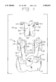
- FIG. 7 is an exploded frontal view of the assembly for forming a deep recess in the distal femur to accomodate an intercondylar housing for a posterior-stabilized femoral component;
- FIG. 8 is a side elevational view of the means for guiding the second tool of the invention for forming a deep recess in the distal femur, shown resting on the bracket which is indicated in phantom;
- FIG. 9 shows the guide means of FIG. 8 alone apart from the bracket
- FIG. 10 is an exploded side elevational view of the bracket of FIG. 8, in combination with a trial insert adapted for reduction in a posterior-stabilized total knee joint;
- FIG. 11 is an exploded frontal view of the combination of FIG. 10.
- FIG. 12 is an external perspective view of a femoral trial component having a posterior-stabilizing housing with modular revision stem.
- a trial implant is generally shown at 10 in FIGS. 1 and 6, comprising a modular bracket, generally indicated at 12, defining a structure having an internal surface (facing the viewer) adapted to be seated on a distal aspect, generally indicated at 14 in FIGS. 3 and 6, of a resected femur bone, shown at 16 in FIGS. 3, 4 and 6.
- the bracket has an external surface (facing the viewer) resembling the normal distal condyle of the femur and any elongated central opening, generally indicated at 18 which is appointed to expose the resected distal aspect 14 of the femur 16.
- Means are provided in the form of parallel tracks or channels 20 for guiding a tool, generally indicated at 22 along a predetermined path in the direction of arrow 24 for controlled shaping of a patellar groove 26 (FIG. 4) in the bone exposed through the opening 18.
- a replaceable insert generally indicated at 19 (FIGS. 1 and 3), covers the opening 16 and articulates with either the normal surface or a prosthesis 32 which is implanted on the resected surface of the proximal aspect 30 of the tibia 34 during interoperative trial reduction of the knee joint as shown in FIG. 6.
- the internal surface of the trial implant 10 is shown comprising a medial 28 and lateral 30 portions of an anterior condylar flange, a pair of posterior condylar flanges 32 which define an intercondylar notch 34 and a series of planar areas.
- the planar areas comprise a smooth metal finish, since tissue ingrowth into the internal surface of the trial implant 10 is not necessary and, in fact, a non-abrasive action is desirable in seating the trial implant 10 on the resected distal aspect 14 of the femur 16.
- 1-6 include a posterior 36, distal 38 and anterior 40 surface.
- a humped distal internal contact surface 42 of the trial implant 10 constitutes the internal surface of the insert 19.
- the internal surfaces of the posterior condyles 32 and the medial 28 and lateral 30 portions of the anterior condyle, respectively also have a smooth metal finish to facilitate onto and off from the resected bone.
- the cleaner surfaces correspond to the resection cuts made in the distal aspect 14 of the femur 16.
- a pair of pegs 44 are formed in the planar surface 38 and project into corresponding holes 45, shown in phantom in FIGS. 3 through 4, bored in the distal aspect 14 of the femur 16.
- the bracket 12 has a pair of alignment notches 46 on opposed sides of opening 18, which align with a pair of corresponding notches 48 formed on opposed sides of the insert 19.
- the insert 19 further comprises a central concave patellar track 50 and a pair of opposed lateral flanges 52 on either side of the patellar track 50.
- the lateral flanges 52 engage the channels 20 of the bracket 12.
- the insert is securely positioned in place on the bracket by a pair of opposed studs 54 which meet with a corresponding pair of apertures 56 formed in the external distal surface of the bracket 12.
- the insert 19 has an interior shoulder 58 which engages in abutment ledge 60 formed in the interior condyle of the bracket 12.
- the insert 19 may be readily positioned within the opening 18 of the bracket 12 by means of a gripping aperature 62 formed in the patellar track 50 of the insert 19; likewise, the alignment notches 48 may also facilitate interoperative removal and replacement of the insert within the opening 18 as needed.
- the shaping tool 22 further comprises a drive shaft 64 rotatably mounted by means of a bearing sleeve 66 to a cutting element, generally indicated at 68, having a plurality of convex-shaped ribs 70 which cut and/or abrade the resected surface of the resected surface of the distal femur to form the patellar groove 26.
- the bearing sleeve 66 extends outwardly from either side of the cutting element 68 and does not rotate with the cutting element 68. Rather, the bearing sleeve 66 rotates independently of the cutting element 68, engaging and traveling along the channels 20 which establishes the predetermined path indicated by the arrow 24 two shapes of patellar groove.
- the insert is replaced into the opening 18 and the knee joint is relocated, as shown in FIG. 63 where the proximal aspect 30 of the tibia 34 has also been resected and a prosthesis 32 implanted, so that the articulating process of the tibial implant engages the patellar track 50 of the condylar prosthesis.
- the tibial prosthesis 32 may be selected from any of a variety of conventional types available to those skilled in the art.
- the tibial prosthesis 32 preferably comprises a metal base plate 74 which is implanted into the resected proximal aspect 30 of the tibia 34 by means of pairs of lateral pegs, shown in phantom at 76 and a central long stem 78 which is fit into the intermedullary canal of the tibia 34.
- the tibial implant 32 is of modular construction, further comprising an upper articulating portion 80, preferably formed of a hard plastic material, for example, high molecular weight polyethylene, to provide a non-degrading articulating surface.
- the upper portion 80 locks into place within the base 75 by means of an arrangement of notches 82 and the upper portion may be replaced when worn without removing the metal base portion 74 implanted into the bone.
- Modular surgical instrumentation and a method of using same as described in conjunction with FIGS. 1-6 above is adapted to form a deep recess in the distal femur to accomodate an intercondylar housing of a posterior-stabilized femoral component, according to the invention, as further shown in FIGS. 7-12.
- This instrumentation (bracketed in FIG. 7) comprises a bracket 312, which has essentially the same construction as the bracket 12 illustrated in FIG. 1 and 3-4 and need not be further described in detail here.
- the bracket 312 defines a generally U-shaped structure which is seated on the distal aspect of the resected femur 13 and has the elongated central opening 323 appointed to expose a selected area of the femur, including curved ledges 340, 342 for guiding the first tool, generally indicated at 22 (see FIG. 5), along a predetermined path for controlled shaping of a curved patellar groove in a portion of the selected area exposed through the opening, substantially as described above with reference to FIG. 3.
- Means generally shown at 300 for guiding a second shaping tool defines a linear bore 302 (shown in phantom) receiving a second tool in the preferred form of an end mill, generally indicated at 304 rotating in the direction of arrow 306, and movable axially in the direction shown by arrow 308, i.e., downwardly toward the resected femur 13 essentially parallel to the long axis of the femoral medullary canal 311 (shown in phantom).
- Bore 302 may have a pair of slots (not shown) which extend tangentially from the bore for receiving a U-shaped punch of the type shown in aforementioned U.S. Ser. No.
- the guide means 300 further comprises a top 314 which is essentially perpendicular to the long axis of the femur and through which bore 302 is formed.
- a pair of legs 316 each having seats 318 which extend in an anterior-posterior direction and have a curved shape to engage the ledges 340, 342 of bracket 312.
- Guide means 300 is aligned with respect to bracket 312 by a pair of positioning holes 320 which respectively engage a pair of pegs 324 projecting distally from the guide means 300, to securely lock the guide means 300 into proper position with respect to bracket 312.
- the bracket 312 can be further secured either to the bone, guide means or both by any suitable arrangement of clips, clamps or the like as will be readily appreciated by those skilled.
- End mill 304 shown in FIGS. 7-9, has a shoulder 328 which bottoms-out in the stop 330 formed at the distal end of bore 302.
- end mill 304 is thus brought down into the surface of the resected femur 13 and then withdrawn, the punch or osteotome alluded to above is impacted with a mallet or the like to finish forming an elongated deep recess for the intercondylar stabilizing housing, until the tip of such punch or osteotome reaches the bottom of the hole formed by end mill 304.
- the surgeon replaces the end mill guide 300 with a different insert, generally shown at 332 which has been modified with a posterior-stabilizing housing, the combination of insert and bracket being collectively denoted by reference numeral 310.
- the insert 332 is positioned on the bracket 312 by locator fingers 334 engaging slots 335, the bracket being, in turn, located on the bone using pegs 336 (FIG. 10).
- the modified insert 332 further comprises an internal wall, indicated in phantom at 338, defining the housing 340, also shown in phantom in FIGS. 10-11.
- a tapered female morse-type connector 342 is provided adjacent the housing 340, receiving a male morse-type connector 344 from a trial stem 346 via keyway 348 which receives key 350, as shown by FIG. 12. Except for the housing 340 and tapered connectors 342, 344, the structure and function of the modular trial component of FIGS. 10-12 is used in performing trial reduction of the knee joint similarly to the femoral trial component discussed relative to FIGS. 1-6 above.
- the method of the invention comprises the steps of seating the bracket described above on the distal aspect of the resected femur and moving the first shaping tool along the curved track to form a patellar groove in a selected area thereof.
- the first shaping tool is then withdrawn and, leaving the bracket in place, while the end mill guid discussed above relative to FIGS. 7-9 is seated on the curved track so that the slotted bore of the guide is accurately aligned with the opening of the bracket, after which the end mill is introduced through the bore to form a deep recess accommodating the intercondylar-stabilizing housing of the trial implant and the trial reduction of the posterior-stabilized knee joint is performed.
Abstract
Description
Claims (8)
Priority Applications (1)
| Application Number | Priority Date | Filing Date | Title |
|---|---|---|---|
| US08/380,363 US5569259A (en) | 1992-02-20 | 1995-01-30 | Modular shaping and trial reduction guide for implantation of femoral prosthesis and method of using same |
Applications Claiming Priority (3)
| Application Number | Priority Date | Filing Date | Title |
|---|---|---|---|
| US07/839,425 US5176684A (en) | 1992-02-20 | 1992-02-20 | Modular shaping and trial reduction guide for implantation of posterior-stabilized femoral prosthesis and method of using same |
| US07/975,247 US5415662A (en) | 1992-02-20 | 1992-11-12 | Modular shaping and trial reduction guide for implantation of posterior-stabilized femoral prosthesis and method of using same |
| US08/380,363 US5569259A (en) | 1992-02-20 | 1995-01-30 | Modular shaping and trial reduction guide for implantation of femoral prosthesis and method of using same |
Related Parent Applications (1)
| Application Number | Title | Priority Date | Filing Date |
|---|---|---|---|
| US07/975,247 Continuation US5415662A (en) | 1992-02-20 | 1992-11-12 | Modular shaping and trial reduction guide for implantation of posterior-stabilized femoral prosthesis and method of using same |
Publications (1)
| Publication Number | Publication Date |
|---|---|
| US5569259A true US5569259A (en) | 1996-10-29 |
Family
ID=25279699
Family Applications (3)
| Application Number | Title | Priority Date | Filing Date |
|---|---|---|---|
| US07/839,425 Expired - Lifetime US5176684A (en) | 1992-02-20 | 1992-02-20 | Modular shaping and trial reduction guide for implantation of posterior-stabilized femoral prosthesis and method of using same |
| US07/975,247 Expired - Lifetime US5415662A (en) | 1992-02-20 | 1992-11-12 | Modular shaping and trial reduction guide for implantation of posterior-stabilized femoral prosthesis and method of using same |
| US08/380,363 Expired - Lifetime US5569259A (en) | 1992-02-20 | 1995-01-30 | Modular shaping and trial reduction guide for implantation of femoral prosthesis and method of using same |
Family Applications Before (2)
| Application Number | Title | Priority Date | Filing Date |
|---|---|---|---|
| US07/839,425 Expired - Lifetime US5176684A (en) | 1992-02-20 | 1992-02-20 | Modular shaping and trial reduction guide for implantation of posterior-stabilized femoral prosthesis and method of using same |
| US07/975,247 Expired - Lifetime US5415662A (en) | 1992-02-20 | 1992-11-12 | Modular shaping and trial reduction guide for implantation of posterior-stabilized femoral prosthesis and method of using same |
Country Status (4)
| Country | Link |
|---|---|
| US (3) | US5176684A (en) |
| EP (1) | EP0556997A1 (en) |
| JP (1) | JPH05277131A (en) |
| CA (1) | CA2089824A1 (en) |
Cited By (49)
| Publication number | Priority date | Publication date | Assignee | Title |
|---|---|---|---|---|
| US5716361A (en) * | 1995-11-02 | 1998-02-10 | Masini; Michael A. | Bone cutting guides for use in the implantation of prosthetic joint components |
| US5916221A (en) * | 1997-09-17 | 1999-06-29 | Bristol-Myers Squibb Company | Notch/chamfer guide |
| US5935132A (en) * | 1997-12-10 | 1999-08-10 | Johnson & Johnson Professional, Inc. | Surgical guide and cutting system |
| US20030093079A1 (en) * | 1997-09-18 | 2003-05-15 | Masini Michael A. | Joint replacement methods and apparatus |
| US20030100906A1 (en) * | 2001-11-28 | 2003-05-29 | Rosa Richard A. | Methods of minimally invasive unicompartmental knee replacement |
| US20030100907A1 (en) * | 2001-11-28 | 2003-05-29 | Rosa Richard A. | Instrumentation for minimally invasive unicompartmental knee replacement |
| US20030158606A1 (en) * | 2002-02-20 | 2003-08-21 | Coon Thomas M. | Knee arthroplasty prosthesis and method |
| US20030220697A1 (en) * | 2002-05-24 | 2003-11-27 | Justin Daniel F. | Modular femoral components for knee arthroplasty |
| US20030225457A1 (en) * | 2002-05-24 | 2003-12-04 | Justin Daniel F. | Femoral components for knee arthroplasty |
| US20040078042A1 (en) * | 1997-09-18 | 2004-04-22 | Masini Michael A. | Bone-conserving orthopedic instrumentation and appliances |
| US20050015153A1 (en) * | 2002-05-24 | 2005-01-20 | Medicine Lodge, Inc. | Implants and related methods and apparatus for securing an implant on an articulating surface of an orthopedic joint |
| US20050143731A1 (en) * | 2003-12-30 | 2005-06-30 | Medicinelodge, Inc. | Tibial condylar hemiplasty tissue preparation instruments and methods |
| US20050143745A1 (en) * | 2003-12-30 | 2005-06-30 | Medicinelodge, Inc. | Instruments and methods for preparing a joint articulation surface for an implant |
| US20050143831A1 (en) * | 2003-12-30 | 2005-06-30 | Medicinelodge, Inc. | Tibial condylar hemiplasty implants, anchor assemblies, and related methods |
| US20050149044A1 (en) * | 2003-12-30 | 2005-07-07 | Medicinelodge, Inc. | Methods and apparatus for forming a tunnel through a proximal end of a tibia |
| US20050154471A1 (en) * | 2004-01-12 | 2005-07-14 | Luke Aram | Systems and methods for compartmental replacement in a knee |
| US20050278034A1 (en) * | 2002-11-22 | 2005-12-15 | Johnson Erin M | Modular knee prosthesis |
| US20060009854A1 (en) * | 2004-07-09 | 2006-01-12 | Medicinelodge, Inc. | Guide templates for surgical implants and related methods |
| US20060058884A1 (en) * | 2004-01-12 | 2006-03-16 | Luke Aram | Systems and methods for compartmental replacement in a knee |
| WO2006069260A1 (en) * | 2004-12-21 | 2006-06-29 | Smith & Nephew, Inc. | Distal femoral trial with removable cutting guide |
| US7115131B2 (en) | 2001-06-14 | 2006-10-03 | Alexandria Research Technologies, Llc | Apparatus and method for sculpting the surface of a joint |
| US20080033448A1 (en) * | 2006-08-04 | 2008-02-07 | Robinson James C | Bone screw removal system |
| WO2008054389A1 (en) * | 2006-10-31 | 2008-05-08 | Smith & Nephew, Inc. | Trial femoral prosthesis and its use |
| US7488347B1 (en) | 2005-01-06 | 2009-02-10 | Medicine Lodge, Inc. | Transosseous graft retention system and method |
| US7544209B2 (en) | 2004-01-12 | 2009-06-09 | Lotke Paul A | Patello-femoral prosthesis |
| US7635390B1 (en) * | 2000-01-14 | 2009-12-22 | Marctec, Llc | Joint replacement component having a modular articulating surface |
| US7641694B1 (en) | 2005-01-06 | 2010-01-05 | IMDS, Inc. | Line lock graft retention system and method |
| US7708741B1 (en) | 2001-08-28 | 2010-05-04 | Marctec, Llc | Method of preparing bones for knee replacement surgery |
| US7799084B2 (en) | 2002-10-23 | 2010-09-21 | Mako Surgical Corp. | Modular femoral component for a total knee joint replacement for minimally invasive implantation |
| US7959635B1 (en) | 2000-01-14 | 2011-06-14 | Marctec, Llc. | Limited incision total joint replacement methods |
| US8002840B2 (en) | 2004-01-12 | 2011-08-23 | Depuy Products, Inc. | Systems and methods for compartmental replacement in a knee |
| US20110218541A1 (en) * | 2010-03-08 | 2011-09-08 | Zimmer, Inc. | Femoral cut guide |
| US8747439B2 (en) | 2000-03-13 | 2014-06-10 | P Tech, Llc | Method of using ultrasonic vibration to secure body tissue with fastening element |
| US8808329B2 (en) | 1998-02-06 | 2014-08-19 | Bonutti Skeletal Innovations Llc | Apparatus and method for securing a portion of a body |
| US8814902B2 (en) | 2000-05-03 | 2014-08-26 | Bonutti Skeletal Innovations Llc | Method of securing body tissue |
| US8845699B2 (en) | 1999-08-09 | 2014-09-30 | Bonutti Skeletal Innovations Llc | Method of securing tissue |
| US8845687B2 (en) | 1996-08-19 | 2014-09-30 | Bonutti Skeletal Innovations Llc | Anchor for securing a suture |
| AU2014203651B2 (en) * | 2006-10-31 | 2016-01-28 | Smith & Nephew, Inc. | Trial femoral prosthesis and its use |
| US9265498B2 (en) | 2003-06-11 | 2016-02-23 | Imds Llc | Compact line locks and methods |
| US20170164959A1 (en) * | 2015-12-15 | 2017-06-15 | Biomet Manufacturing, Llc | Associated instruments and methods for posterior stabilized knee preparation |
| US9770238B2 (en) | 2001-12-03 | 2017-09-26 | P Tech, Llc | Magnetic positioning apparatus |
| US10363147B2 (en) | 2016-05-18 | 2019-07-30 | Depuy Ireland Unlimited Company | System and method for preparing a patient's femur in an orthopaedic joint replacement procedure |
| US10470899B2 (en) | 2016-05-18 | 2019-11-12 | Depuy Ireland Unlimited Company | Method for preparing a patient's tibia in an orthopaedic joint replacement procedure |
| US10537341B2 (en) | 2017-09-20 | 2020-01-21 | Depuy Ireland Unlimited Company | Orthopaedic system and method for assembling prosthetic components |
| US10537446B2 (en) | 2017-09-20 | 2020-01-21 | Depuy Ireland Unlimited Company | Method and instruments for assembling an orthopaedic prosthesis |
| US10543001B2 (en) | 2017-09-20 | 2020-01-28 | Depuy Ireland Unlimited Company | Method and instruments for assembling a femoral orthopaedic prosthesis |
| US10940024B2 (en) | 2017-07-26 | 2021-03-09 | Optimotion Implants LLC | Universal femoral trial system and methods |
| US11406502B2 (en) | 2017-03-02 | 2022-08-09 | Optimotion Implants LLC | Orthopedic implants and methods |
| US11439409B2 (en) | 2019-09-18 | 2022-09-13 | Depuy Ireland Unlimited Company | Cutting block |
Families Citing this family (141)
| Publication number | Priority date | Publication date | Assignee | Title |
|---|---|---|---|---|
| US5344423A (en) * | 1992-02-06 | 1994-09-06 | Zimmer, Inc. | Apparatus and method for milling bone |
| US5176684A (en) * | 1992-02-20 | 1993-01-05 | Dow Corning Wright | Modular shaping and trial reduction guide for implantation of posterior-stabilized femoral prosthesis and method of using same |
| US5417695A (en) * | 1992-07-27 | 1995-05-23 | Pfizer Hospital Products Group, Inc. | Instrumentation for preparing a distal femur |
| CA2098081A1 (en) * | 1992-08-13 | 1994-02-14 | Terry L. Dietz | Alignment guide and method |
| US5405395A (en) * | 1993-05-03 | 1995-04-11 | Wright Medical Technology, Inc. | Modular femoral implant |
| FR2705885B1 (en) * | 1993-06-01 | 1995-07-28 | Medinov Sa | Installation set for a unicompartmental knee prosthesis. |
| CA2126627C (en) * | 1993-07-06 | 2005-01-25 | Kim C. Bertin | Femoral milling instrumentation for use in total knee arthroplasty with optional cutting guide attachment |
| US5474559A (en) * | 1993-07-06 | 1995-12-12 | Zimmer, Inc. | Femoral milling instrumentation for use in total knee arthroplasty with optional cutting guide attachment |
| FR2719762B1 (en) * | 1994-05-13 | 1996-07-12 | Smith & Nephew Richards France | Trochlear implant for femoro-patellar prosthesis and its fitting instrumentation. |
| US5908424A (en) * | 1994-05-16 | 1999-06-01 | Zimmer, Inc, By Said Stalcup, Dietz, Bays And Vanlaningham | Tibial milling guide system |
| ES2149992T3 (en) * | 1994-06-02 | 2000-11-16 | Sulzer Orthopedics Inc | INSTRUMENT USED TO PERFORM AN INTERCONDILIAN CUT FOR A STABILIZED REAR FEMORAL KNEE PROSTHESIS. |
| FR2721202B1 (en) * | 1994-06-16 | 1996-10-04 | Patrick Marie Crol Labourdette | Femoro-patellar prosthesis and ancillary device to form a trochlear impression of reception of this prosthesis. |
| US5571196A (en) * | 1994-10-24 | 1996-11-05 | Stein; Daniel | Patello-femoral joint replacement device and method |
| US5824098A (en) * | 1994-10-24 | 1998-10-20 | Stein; Daniel | Patello-femoral joint replacement device and method |
| US5549689A (en) * | 1994-11-28 | 1996-08-27 | Epstein; Norman | Prosthetic knee |
| US5514183A (en) * | 1994-12-20 | 1996-05-07 | Epstein; Norman | Reduced friction prosthetic knee joint utilizing replaceable roller bearings |
| CA2168509A1 (en) * | 1995-02-13 | 1996-08-14 | Gregory C. Stalcup | Orthopaedic milling guide with cutter lockout |
| US5593411A (en) * | 1995-03-13 | 1997-01-14 | Zimmer, Inc. | Orthopaedic milling guide for milling intersecting planes |
| US5601563A (en) * | 1995-08-25 | 1997-02-11 | Zimmer, Inc. | Orthopaedic milling template with attachable cutting guide |
| US20020143402A1 (en) * | 1995-09-04 | 2002-10-03 | Limber Ltd. | Hip joint prostheses |
| US5658293A (en) * | 1995-10-10 | 1997-08-19 | Zimmer, Inc. | Guide platform associated with intramedullary rod |
| US5653714A (en) * | 1996-02-22 | 1997-08-05 | Zimmer, Inc. | Dual slide cutting guide |
| US5769854A (en) * | 1996-08-23 | 1998-06-23 | Osteonics Corp. | Instrument system for preparing a distal femur for a posteriorly stabilized femoral component of a knee prosthesis |
| US5766255A (en) * | 1996-12-23 | 1998-06-16 | Johnson & Johnson Professional, Inc. | Modular joint prosthesis stabilization and augmentation system |
| US5735856A (en) * | 1997-01-31 | 1998-04-07 | Johnson & Johnson Professional, Inc. | Orthopedic cutting guide and bushing |
| US5976147A (en) * | 1997-07-11 | 1999-11-02 | Johnson & Johnson Professional, Inc | Modular instrumentation for bone preparation and implant trial reduction of orthopedic implants |
| US6475230B1 (en) * | 1997-08-01 | 2002-11-05 | Peter M. Bonutti | Method and apparatus for securing a suture |
| US7104996B2 (en) * | 2000-01-14 | 2006-09-12 | Marctec. Llc | Method of performing surgery |
| US6821470B2 (en) * | 2001-06-29 | 2004-11-23 | Depuy Products, Inc. | Joint prosthesis molding method |
| US6962607B2 (en) * | 2001-06-30 | 2005-11-08 | Depuy Products, Inc. | Joint replacement prosthesis component with non linear insert |
| CN1596091A (en) | 2001-12-04 | 2005-03-16 | 迪斯酋有限公司 | Implants for load bearing applications |
| EP1480582B1 (en) * | 2002-02-14 | 2012-07-18 | Biomet Spain Orthopaedics S.L. | Patello-femoral joint replacement |
| US7182786B2 (en) | 2002-04-25 | 2007-02-27 | Zimmer Technology, Inc. | Modular bone implant, tool, and method |
| ES2323775T3 (en) * | 2002-05-23 | 2009-07-24 | Active Implants Corporation | DENTAL AND ARTICULATION IMPLANTS. |
| US20040039395A1 (en) * | 2002-05-24 | 2004-02-26 | Coon Thomas M. | Instruments for knee surgery and method of use |
| US20040133209A1 (en) * | 2002-09-19 | 2004-07-08 | Chappuis James L. | Medical bur |
| US20040153066A1 (en) * | 2003-02-03 | 2004-08-05 | Coon Thomas M. | Apparatus for knee surgery and method of use |
| US7547327B2 (en) * | 2003-10-03 | 2009-06-16 | Howmedica Osteonics Corp. | Expandable augment trial |
| US7364580B2 (en) * | 2003-10-08 | 2008-04-29 | Biomet Manufacturing Corp. | Bone-cutting apparatus |
| US7806898B2 (en) | 2004-07-09 | 2010-10-05 | Zimmer, Inc. | Modular guide systems and related rasps and methods for resecting a joint articulation surface |
| US7927336B2 (en) * | 2005-02-08 | 2011-04-19 | Rasmussen G Lynn | Guide assembly for guiding cuts to a femur and tibia during a knee arthroplasty |
| US8303597B2 (en) | 2005-02-08 | 2012-11-06 | Rasmussen G Lynn | Systems and methods for guiding cuts to a femur and tibia during a knee arthroplasty |
| US8317797B2 (en) | 2005-02-08 | 2012-11-27 | Rasmussen G Lynn | Arthroplasty systems and methods for optimally aligning and tensioning a knee prosthesis |
| US7695477B2 (en) * | 2005-05-26 | 2010-04-13 | Zimmer, Inc. | Milling system and methods for resecting a joint articulation surface |
| US7727239B2 (en) * | 2005-06-10 | 2010-06-01 | Zimmer Technology, Inc. | Milling system with guide paths and related methods for resecting a joint articulation surface |
| US8142509B2 (en) | 2006-01-23 | 2012-03-27 | Smith & Nephew, Inc. | Patellar components |
| US8864769B2 (en) * | 2006-02-27 | 2014-10-21 | Biomet Manufacturing, Llc | Alignment guides with patient-specific anchoring elements |
| US8282646B2 (en) | 2006-02-27 | 2012-10-09 | Biomet Manufacturing Corp. | Patient specific knee alignment guide and associated method |
| US8608749B2 (en) | 2006-02-27 | 2013-12-17 | Biomet Manufacturing, Llc | Patient-specific acetabular guides and associated instruments |
| US8241293B2 (en) * | 2006-02-27 | 2012-08-14 | Biomet Manufacturing Corp. | Patient specific high tibia osteotomy |
| US9173661B2 (en) | 2006-02-27 | 2015-11-03 | Biomet Manufacturing, Llc | Patient specific alignment guide with cutting surface and laser indicator |
| US8377066B2 (en) | 2006-02-27 | 2013-02-19 | Biomet Manufacturing Corp. | Patient-specific elbow guides and associated methods |
| US8568487B2 (en) * | 2006-02-27 | 2013-10-29 | Biomet Manufacturing, Llc | Patient-specific hip joint devices |
| US20080257363A1 (en) * | 2007-04-17 | 2008-10-23 | Biomet Manufacturing Corp. | Method And Apparatus For Manufacturing An Implant |
| US20110172672A1 (en) * | 2006-02-27 | 2011-07-14 | Biomet Manufacturing Corp. | Instrument with transparent portion for use with patient-specific alignment guide |
| US9907659B2 (en) | 2007-04-17 | 2018-03-06 | Biomet Manufacturing, Llc | Method and apparatus for manufacturing an implant |
| US8092465B2 (en) | 2006-06-09 | 2012-01-10 | Biomet Manufacturing Corp. | Patient specific knee alignment guide and associated method |
| US8858561B2 (en) * | 2006-06-09 | 2014-10-14 | Blomet Manufacturing, LLC | Patient-specific alignment guide |
| US9339278B2 (en) | 2006-02-27 | 2016-05-17 | Biomet Manufacturing, Llc | Patient-specific acetabular guides and associated instruments |
| US9918740B2 (en) | 2006-02-27 | 2018-03-20 | Biomet Manufacturing, Llc | Backup surgical instrument system and method |
| US8133234B2 (en) * | 2006-02-27 | 2012-03-13 | Biomet Manufacturing Corp. | Patient specific acetabular guide and method |
| US10278711B2 (en) * | 2006-02-27 | 2019-05-07 | Biomet Manufacturing, Llc | Patient-specific femoral guide |
| US20110190899A1 (en) * | 2006-02-27 | 2011-08-04 | Biomet Manufacturing Corp. | Patient-specific augments |
| US8473305B2 (en) * | 2007-04-17 | 2013-06-25 | Biomet Manufacturing Corp. | Method and apparatus for manufacturing an implant |
| US8608748B2 (en) * | 2006-02-27 | 2013-12-17 | Biomet Manufacturing, Llc | Patient specific guides |
| US8603180B2 (en) | 2006-02-27 | 2013-12-10 | Biomet Manufacturing, Llc | Patient-specific acetabular alignment guides |
| US8591516B2 (en) | 2006-02-27 | 2013-11-26 | Biomet Manufacturing, Llc | Patient-specific orthopedic instruments |
| US7967868B2 (en) | 2007-04-17 | 2011-06-28 | Biomet Manufacturing Corp. | Patient-modified implant and associated method |
| US8070752B2 (en) * | 2006-02-27 | 2011-12-06 | Biomet Manufacturing Corp. | Patient specific alignment guide and inter-operative adjustment |
| US20150335438A1 (en) | 2006-02-27 | 2015-11-26 | Biomet Manufacturing, Llc. | Patient-specific augments |
| US9113971B2 (en) | 2006-02-27 | 2015-08-25 | Biomet Manufacturing, Llc | Femoral acetabular impingement guide |
| US9289253B2 (en) | 2006-02-27 | 2016-03-22 | Biomet Manufacturing, Llc | Patient-specific shoulder guide |
| US8407067B2 (en) | 2007-04-17 | 2013-03-26 | Biomet Manufacturing Corp. | Method and apparatus for manufacturing an implant |
| US9345548B2 (en) * | 2006-02-27 | 2016-05-24 | Biomet Manufacturing, Llc | Patient-specific pre-operative planning |
| US8535387B2 (en) | 2006-02-27 | 2013-09-17 | Biomet Manufacturing, Llc | Patient-specific tools and implants |
| US8298237B2 (en) * | 2006-06-09 | 2012-10-30 | Biomet Manufacturing Corp. | Patient-specific alignment guide for multiple incisions |
| US9795399B2 (en) | 2006-06-09 | 2017-10-24 | Biomet Manufacturing, Llc | Patient-specific knee alignment guide and associated method |
| WO2008069800A1 (en) | 2006-12-07 | 2008-06-12 | Anatol Podolsky | Method and apparatus for total hip replacement |
| US8579985B2 (en) | 2006-12-07 | 2013-11-12 | Ihip Surgical, Llc | Method and apparatus for hip replacement |
| US8974540B2 (en) | 2006-12-07 | 2015-03-10 | Ihip Surgical, Llc | Method and apparatus for attachment in a modular hip replacement or fracture fixation device |
| US8265949B2 (en) | 2007-09-27 | 2012-09-11 | Depuy Products, Inc. | Customized patient surgical plan |
| EP2957244B1 (en) | 2007-09-30 | 2020-04-15 | DePuy Products, Inc. | Method of generating a customized patient-specific orthopaedic surgical instrumentation |
| US8357111B2 (en) | 2007-09-30 | 2013-01-22 | Depuy Products, Inc. | Method and system for designing patient-specific orthopaedic surgical instruments |
| US8920427B2 (en) * | 2008-08-01 | 2014-12-30 | DePuy Synthes Products, LLC | Orthopaedic surgical method for performing a patellofemoral arthroplasty procedure |
| US8562608B2 (en) * | 2008-09-19 | 2013-10-22 | Zimmer, Inc. | Patello-femoral milling system |
| US9375221B2 (en) | 2008-12-29 | 2016-06-28 | Depuy (Ireland) | Orthopaedic cutting block having a chemically etched metal insert |
| US20100168752A1 (en) * | 2008-12-29 | 2010-07-01 | Edwards Jon M | Orthopaedic cutting tool having a chemically etched metal insert and method of manufacturing |
| US8170641B2 (en) * | 2009-02-20 | 2012-05-01 | Biomet Manufacturing Corp. | Method of imaging an extremity of a patient |
| US8480753B2 (en) * | 2009-02-27 | 2013-07-09 | Howmedica Osteonics Corp. | Spot facing trochlear groove |
| US20100222782A1 (en) * | 2009-02-27 | 2010-09-02 | Howmedica Osteonics Corp. | Spot facing trochlear groove |
| CA2764002A1 (en) | 2009-05-29 | 2010-12-02 | Smith & Nephew, Inc. | Methods and apparatus for performing knee arthroplasty |
| DE102009028503B4 (en) | 2009-08-13 | 2013-11-14 | Biomet Manufacturing Corp. | Resection template for the resection of bones, method for producing such a resection template and operation set for performing knee joint surgery |
| JP2011139785A (en) * | 2010-01-07 | 2011-07-21 | Nakashima Medical Co Ltd | Nail insertion type artificial knee joint |
| US8632547B2 (en) * | 2010-02-26 | 2014-01-21 | Biomet Sports Medicine, Llc | Patient-specific osteotomy devices and methods |
| US9066727B2 (en) | 2010-03-04 | 2015-06-30 | Materialise Nv | Patient-specific computed tomography guides |
| US8974459B1 (en) | 2010-05-21 | 2015-03-10 | Howmedica Osteonics Corp. | Natural alignment knee instruments |
| US9271744B2 (en) | 2010-09-29 | 2016-03-01 | Biomet Manufacturing, Llc | Patient-specific guide for partial acetabular socket replacement |
| US8747410B2 (en) | 2010-10-26 | 2014-06-10 | Zimmer, Inc. | Patellar resection instrument with variable depth guide |
| US9968376B2 (en) | 2010-11-29 | 2018-05-15 | Biomet Manufacturing, Llc | Patient-specific orthopedic instruments |
| US9241745B2 (en) | 2011-03-07 | 2016-01-26 | Biomet Manufacturing, Llc | Patient-specific femoral version guide |
| US8715289B2 (en) | 2011-04-15 | 2014-05-06 | Biomet Manufacturing, Llc | Patient-specific numerically controlled instrument |
| US9675400B2 (en) | 2011-04-19 | 2017-06-13 | Biomet Manufacturing, Llc | Patient-specific fracture fixation instrumentation and method |
| US8668700B2 (en) | 2011-04-29 | 2014-03-11 | Biomet Manufacturing, Llc | Patient-specific convertible guides |
| US8956364B2 (en) | 2011-04-29 | 2015-02-17 | Biomet Manufacturing, Llc | Patient-specific partial knee guides and other instruments |
| US8532807B2 (en) | 2011-06-06 | 2013-09-10 | Biomet Manufacturing, Llc | Pre-operative planning and manufacturing method for orthopedic procedure |
| US8979847B2 (en) | 2011-06-06 | 2015-03-17 | Biomet Manufacturing, Llc | Method and apparatus for implanting a knee prosthesis |
| US9084618B2 (en) | 2011-06-13 | 2015-07-21 | Biomet Manufacturing, Llc | Drill guides for confirming alignment of patient-specific alignment guides |
| US20130001121A1 (en) | 2011-07-01 | 2013-01-03 | Biomet Manufacturing Corp. | Backup kit for a patient-specific arthroplasty kit assembly |
| US8764760B2 (en) | 2011-07-01 | 2014-07-01 | Biomet Manufacturing, Llc | Patient-specific bone-cutting guidance instruments and methods |
| US8597365B2 (en) | 2011-08-04 | 2013-12-03 | Biomet Manufacturing, Llc | Patient-specific pelvic implants for acetabular reconstruction |
| US9295497B2 (en) | 2011-08-31 | 2016-03-29 | Biomet Manufacturing, Llc | Patient-specific sacroiliac and pedicle guides |
| US9066734B2 (en) | 2011-08-31 | 2015-06-30 | Biomet Manufacturing, Llc | Patient-specific sacroiliac guides and associated methods |
| US9386993B2 (en) | 2011-09-29 | 2016-07-12 | Biomet Manufacturing, Llc | Patient-specific femoroacetabular impingement instruments and methods |
| EP2770918B1 (en) | 2011-10-27 | 2017-07-19 | Biomet Manufacturing, LLC | Patient-specific glenoid guides |
| US9451973B2 (en) | 2011-10-27 | 2016-09-27 | Biomet Manufacturing, Llc | Patient specific glenoid guide |
| US9301812B2 (en) | 2011-10-27 | 2016-04-05 | Biomet Manufacturing, Llc | Methods for patient-specific shoulder arthroplasty |
| KR20130046336A (en) | 2011-10-27 | 2013-05-07 | 삼성전자주식회사 | Multi-view device of display apparatus and contol method thereof, and display system |
| US9554910B2 (en) | 2011-10-27 | 2017-01-31 | Biomet Manufacturing, Llc | Patient-specific glenoid guide and implants |
| US9237950B2 (en) | 2012-02-02 | 2016-01-19 | Biomet Manufacturing, Llc | Implant with patient-specific porous structure |
| JP5662401B2 (en) * | 2012-10-05 | 2015-01-28 | スミス アンド ネフュー インコーポレーテッド | Experimental femoral prosthesis and use thereof |
| US9204977B2 (en) | 2012-12-11 | 2015-12-08 | Biomet Manufacturing, Llc | Patient-specific acetabular guide for anterior approach |
| US9060788B2 (en) | 2012-12-11 | 2015-06-23 | Biomet Manufacturing, Llc | Patient-specific acetabular guide for anterior approach |
| US9839438B2 (en) | 2013-03-11 | 2017-12-12 | Biomet Manufacturing, Llc | Patient-specific glenoid guide with a reusable guide holder |
| US9579107B2 (en) | 2013-03-12 | 2017-02-28 | Biomet Manufacturing, Llc | Multi-point fit for patient specific guide |
| US9498233B2 (en) | 2013-03-13 | 2016-11-22 | Biomet Manufacturing, Llc. | Universal acetabular guide and associated hardware |
| US9826981B2 (en) | 2013-03-13 | 2017-11-28 | Biomet Manufacturing, Llc | Tangential fit of patient-specific guides |
| US9517145B2 (en) | 2013-03-15 | 2016-12-13 | Biomet Manufacturing, Llc | Guide alignment system and method |
| US20150112349A1 (en) | 2013-10-21 | 2015-04-23 | Biomet Manufacturing, Llc | Ligament Guide Registration |
| US9655727B2 (en) | 2013-12-12 | 2017-05-23 | Stryker Corporation | Extended patellofemoral |
| US10282488B2 (en) | 2014-04-25 | 2019-05-07 | Biomet Manufacturing, Llc | HTO guide with optional guided ACL/PCL tunnels |
| US9408616B2 (en) | 2014-05-12 | 2016-08-09 | Biomet Manufacturing, Llc | Humeral cut guide |
| US9839436B2 (en) | 2014-06-03 | 2017-12-12 | Biomet Manufacturing, Llc | Patient-specific glenoid depth control |
| US9561040B2 (en) | 2014-06-03 | 2017-02-07 | Biomet Manufacturing, Llc | Patient-specific glenoid depth control |
| US9826994B2 (en) | 2014-09-29 | 2017-11-28 | Biomet Manufacturing, Llc | Adjustable glenoid pin insertion guide |
| US9833245B2 (en) | 2014-09-29 | 2017-12-05 | Biomet Sports Medicine, Llc | Tibial tubercule osteotomy |
| US9820868B2 (en) | 2015-03-30 | 2017-11-21 | Biomet Manufacturing, Llc | Method and apparatus for a pin apparatus |
| US10226262B2 (en) | 2015-06-25 | 2019-03-12 | Biomet Manufacturing, Llc | Patient-specific humeral guide designs |
| US10568647B2 (en) | 2015-06-25 | 2020-02-25 | Biomet Manufacturing, Llc | Patient-specific humeral guide designs |
| US10722310B2 (en) | 2017-03-13 | 2020-07-28 | Zimmer Biomet CMF and Thoracic, LLC | Virtual surgery planning system and method |
| US10925743B2 (en) * | 2017-09-26 | 2021-02-23 | Stephen J. Incavo | Knee arthroplasty with modular femoral adapters |
| US11051829B2 (en) | 2018-06-26 | 2021-07-06 | DePuy Synthes Products, Inc. | Customized patient-specific orthopaedic surgical instrument |
Citations (7)
| Publication number | Priority date | Publication date | Assignee | Title |
|---|---|---|---|---|
| US4474177A (en) * | 1983-03-09 | 1984-10-02 | Wright Manufacturing Company | Method and apparatus for shaping a distal femoral surface |
| US4721104A (en) * | 1985-12-02 | 1988-01-26 | Dow Corning Wright Corporation | Femoral surface shaping apparatus for posterior-stabilized knee implants |
| US4722330A (en) * | 1986-04-22 | 1988-02-02 | Dow Corning Wright Corporation | Femoral surface shaping guide for knee implants |
| US4787383A (en) * | 1985-12-19 | 1988-11-29 | Howmedica, Inc. | Prosthetic knee implantation |
| US4825857A (en) * | 1982-02-18 | 1989-05-02 | Howmedica, Inc. | Prosthetic knee implantation |
| US5035700A (en) * | 1988-02-03 | 1991-07-30 | Pfizer Hospital Products Group, Inc. | Prosthetic knee joint with improved patellar component tracking |
| US5037423A (en) * | 1983-10-26 | 1991-08-06 | Pfizer Hospital Products Group, Inc. | Method and instrumentation for the replacement of a knee prosthesis |
Family Cites Families (10)
| Publication number | Priority date | Publication date | Assignee | Title |
|---|---|---|---|---|
| US4219893A (en) * | 1977-09-01 | 1980-09-02 | United States Surgical Corporation | Prosthetic knee joint |
| US4217666A (en) * | 1979-04-05 | 1980-08-19 | Minnesota Mining And Manufacturing Company | Tibial prosthesis having a U-shaped intramedullary stem |
| US4653488A (en) * | 1982-02-18 | 1987-03-31 | Howmedica, Inc. | Prosthetic knee implantation |
| GB2120943B (en) * | 1982-03-13 | 1985-04-11 | Thackray C F Ltd | Knee prosthesis |
| US4502483A (en) * | 1983-03-09 | 1985-03-05 | Dow Corning Corporation | Method and apparatus for shaping a distal femoral surface |
| US5007933A (en) * | 1989-01-31 | 1991-04-16 | Osteonics Corp. | Modular knee prosthesis system |
| US5035699A (en) * | 1990-01-09 | 1991-07-30 | Dow Corning Wright | Patella track cutter and guide |
| US5098436A (en) * | 1991-03-07 | 1992-03-24 | Dow Corning Wright Corporation | Modular guide for shaping of femur to accommodate intercondylar stabilizing housing and patellar track of implant |
| US5100409A (en) * | 1991-03-07 | 1992-03-31 | Dow Corning Wright Corporation | Shaping and trial reduction guide for implantation of femoral prosthesis and method of using same |
| US5176684A (en) * | 1992-02-20 | 1993-01-05 | Dow Corning Wright | Modular shaping and trial reduction guide for implantation of posterior-stabilized femoral prosthesis and method of using same |
-
1992
- 1992-02-20 US US07/839,425 patent/US5176684A/en not_active Expired - Lifetime
- 1992-11-12 US US07/975,247 patent/US5415662A/en not_active Expired - Lifetime
-
1993
- 1993-02-10 EP EP93300942A patent/EP0556997A1/en not_active Ceased
- 1993-02-18 CA CA002089824A patent/CA2089824A1/en not_active Abandoned
- 1993-02-19 JP JP5030210A patent/JPH05277131A/en active Pending
-
1995
- 1995-01-30 US US08/380,363 patent/US5569259A/en not_active Expired - Lifetime
Patent Citations (7)
| Publication number | Priority date | Publication date | Assignee | Title |
|---|---|---|---|---|
| US4825857A (en) * | 1982-02-18 | 1989-05-02 | Howmedica, Inc. | Prosthetic knee implantation |
| US4474177A (en) * | 1983-03-09 | 1984-10-02 | Wright Manufacturing Company | Method and apparatus for shaping a distal femoral surface |
| US5037423A (en) * | 1983-10-26 | 1991-08-06 | Pfizer Hospital Products Group, Inc. | Method and instrumentation for the replacement of a knee prosthesis |
| US4721104A (en) * | 1985-12-02 | 1988-01-26 | Dow Corning Wright Corporation | Femoral surface shaping apparatus for posterior-stabilized knee implants |
| US4787383A (en) * | 1985-12-19 | 1988-11-29 | Howmedica, Inc. | Prosthetic knee implantation |
| US4722330A (en) * | 1986-04-22 | 1988-02-02 | Dow Corning Wright Corporation | Femoral surface shaping guide for knee implants |
| US5035700A (en) * | 1988-02-03 | 1991-07-30 | Pfizer Hospital Products Group, Inc. | Prosthetic knee joint with improved patellar component tracking |
Cited By (146)
| Publication number | Priority date | Publication date | Assignee | Title |
|---|---|---|---|---|
| US6602259B1 (en) | 1995-11-02 | 2003-08-05 | Medidea, Llc | Bone cutting guides for use in the implantation of prosthetic joint components |
| US5885296A (en) * | 1995-11-02 | 1999-03-23 | Medidea, Llc | Bone cutting guides with removable housings for use in the implantation of prosthetic joint components |
| US5897559A (en) * | 1995-11-02 | 1999-04-27 | Medidea, Llc | Bone cutting guides for use in the implantation of prosthetic joint components |
| US5716361A (en) * | 1995-11-02 | 1998-02-10 | Masini; Michael A. | Bone cutting guides for use in the implantation of prosthetic joint components |
| US6187010B1 (en) | 1995-11-02 | 2001-02-13 | Medidea, Llc | Bone cutting guides for use in the implantation of prosthetic joint components |
| US8845687B2 (en) | 1996-08-19 | 2014-09-30 | Bonutti Skeletal Innovations Llc | Anchor for securing a suture |
| US5916221A (en) * | 1997-09-17 | 1999-06-29 | Bristol-Myers Squibb Company | Notch/chamfer guide |
| US7128745B2 (en) | 1997-09-18 | 2006-10-31 | Medidea, Llc | Joint replacement methods and apparatus |
| US7419491B2 (en) | 1997-09-18 | 2008-09-02 | Medidea, Llc | Bone-conserving orthopedic instrumentation and appliances |
| US20030093079A1 (en) * | 1997-09-18 | 2003-05-15 | Masini Michael A. | Joint replacement methods and apparatus |
| US20040078042A1 (en) * | 1997-09-18 | 2004-04-22 | Masini Michael A. | Bone-conserving orthopedic instrumentation and appliances |
| US20040078043A1 (en) * | 1997-09-18 | 2004-04-22 | Masini Michael A. | Joint replacement methods and apparatus |
| US5935132A (en) * | 1997-12-10 | 1999-08-10 | Johnson & Johnson Professional, Inc. | Surgical guide and cutting system |
| US8808329B2 (en) | 1998-02-06 | 2014-08-19 | Bonutti Skeletal Innovations Llc | Apparatus and method for securing a portion of a body |
| US8845699B2 (en) | 1999-08-09 | 2014-09-30 | Bonutti Skeletal Innovations Llc | Method of securing tissue |
| US8784495B2 (en) | 2000-01-14 | 2014-07-22 | Bonutti Skeletal Innovations Llc | Segmental knee arthroplasty |
| US7892236B1 (en) | 2000-01-14 | 2011-02-22 | Marctec, Llc | System and method for total joint replacement |
| US9101443B2 (en) | 2000-01-14 | 2015-08-11 | Bonutti Skeletal Innovations Llc | Methods for robotic arthroplasty |
| US9192459B2 (en) | 2000-01-14 | 2015-11-24 | Bonutti Skeletal Innovations Llc | Method of performing total knee arthroplasty |
| US9795394B2 (en) | 2000-01-14 | 2017-10-24 | Bonutti Skeletal Innovations Llc | Method for placing implant using robotic system |
| US8632552B2 (en) | 2000-01-14 | 2014-01-21 | Bonutti Skeletal Innovations Llc | Method of preparing a femur and tibia in knee arthroplasty |
| US8425522B2 (en) | 2000-01-14 | 2013-04-23 | Bonutti Skeletal Innovations Llc | Joint replacement method |
| US8133229B1 (en) | 2000-01-14 | 2012-03-13 | Marctec, Llc. | Knee arthroplasty method |
| US7959635B1 (en) | 2000-01-14 | 2011-06-14 | Marctec, Llc. | Limited incision total joint replacement methods |
| US7931690B1 (en) | 2000-01-14 | 2011-04-26 | Marctec, Llc | Method of resurfacing an articular surface of a bone |
| US7635390B1 (en) * | 2000-01-14 | 2009-12-22 | Marctec, Llc | Joint replacement component having a modular articulating surface |
| US7708740B1 (en) | 2000-01-14 | 2010-05-04 | Marctec, Llc | Method for total knee arthroplasty and resecting bone in situ |
| US7837736B2 (en) | 2000-01-14 | 2010-11-23 | Marctec, Llc | Minimally invasive surgical systems and methods |
| US7828852B2 (en) | 2000-01-14 | 2010-11-09 | Marctec, Llc. | Inlaid articular implant |
| US7806897B1 (en) | 2000-01-14 | 2010-10-05 | Marctec, Llc | Knee arthroplasty and preservation of the quadriceps mechanism |
| US7806896B1 (en) | 2000-01-14 | 2010-10-05 | Marctec, Llc | Knee arthroplasty method |
| US7749229B1 (en) | 2000-01-14 | 2010-07-06 | Marctec, Llc | Total knee arthroplasty through shortened incision |
| US8747439B2 (en) | 2000-03-13 | 2014-06-10 | P Tech, Llc | Method of using ultrasonic vibration to secure body tissue with fastening element |
| US8814902B2 (en) | 2000-05-03 | 2014-08-26 | Bonutti Skeletal Innovations Llc | Method of securing body tissue |
| US7896922B2 (en) | 2001-06-14 | 2011-03-01 | Alexandria Research Technologies, Llc | Implants for partial knee arthroplasty |
| US7520901B2 (en) | 2001-06-14 | 2009-04-21 | Alexandria Research Technologies, Inc. | Bicompartmental implants and method of use |
| US7115131B2 (en) | 2001-06-14 | 2006-10-03 | Alexandria Research Technologies, Llc | Apparatus and method for sculpting the surface of a joint |
| US9060797B2 (en) | 2001-08-28 | 2015-06-23 | Bonutti Skeletal Innovations Llc | Method of preparing a femur and tibia in knee arthroplasty |
| US8840629B2 (en) | 2001-08-28 | 2014-09-23 | Bonutti Skeletal Innovations Llc | Robotic arthroplasty system including navigation |
| US10470780B2 (en) | 2001-08-28 | 2019-11-12 | Bonutti Skeletal Innovations Llc | Systems and methods for ligament balancing in robotic surgery |
| US8858557B2 (en) | 2001-08-28 | 2014-10-14 | Bonutti Skeletal Innovations Llc | Method of preparing a femur and tibia in knee arthroplasty |
| US8834490B2 (en) | 2001-08-28 | 2014-09-16 | Bonutti Skeletal Innovations Llc | Method for robotic arthroplasty using navigation |
| US10321918B2 (en) | 2001-08-28 | 2019-06-18 | Bonutti Skeletal Innovations Llc | Methods for robotic surgery using a cannula |
| US10231739B1 (en) | 2001-08-28 | 2019-03-19 | Bonutti Skeletal Innovations Llc | System and method for robotic surgery |
| US8641726B2 (en) | 2001-08-28 | 2014-02-04 | Bonutti Skeletal Innovations Llc | Method for robotic arthroplasty using navigation |
| US8623030B2 (en) | 2001-08-28 | 2014-01-07 | Bonutti Skeletal Innovations Llc | Robotic arthroplasty system including navigation |
| US7708741B1 (en) | 2001-08-28 | 2010-05-04 | Marctec, Llc | Method of preparing bones for knee replacement surgery |
| US9763683B2 (en) | 2001-08-28 | 2017-09-19 | Bonutti Skeletal Innovations Llc | Method for performing surgical procedures using optical cutting guides |
| US7141053B2 (en) | 2001-11-28 | 2006-11-28 | Wright Medical Technology, Inc. | Methods of minimally invasive unicompartmental knee replacement |
| US7060074B2 (en) | 2001-11-28 | 2006-06-13 | Wright Medical Technology, Inc. | Instrumentation for minimally invasive unicompartmental knee replacement |
| US20030100906A1 (en) * | 2001-11-28 | 2003-05-29 | Rosa Richard A. | Methods of minimally invasive unicompartmental knee replacement |
| US20030100907A1 (en) * | 2001-11-28 | 2003-05-29 | Rosa Richard A. | Instrumentation for minimally invasive unicompartmental knee replacement |
| US9770238B2 (en) | 2001-12-03 | 2017-09-26 | P Tech, Llc | Magnetic positioning apparatus |
| US20050283251A1 (en) * | 2002-02-20 | 2005-12-22 | Coon Thomas M | Knee arthroplasty prosthesis and method |
| US20030158606A1 (en) * | 2002-02-20 | 2003-08-21 | Coon Thomas M. | Knee arthroplasty prosthesis and method |
| US9072605B2 (en) | 2002-02-20 | 2015-07-07 | Zimmer, Inc. | Knee arthroplasty prosthesis |
| US20050283253A1 (en) * | 2002-02-20 | 2005-12-22 | Coon Thomas M | Knee arthroplasty prosthesis and method |
| US20050283252A1 (en) * | 2002-02-20 | 2005-12-22 | Coon Thomas M | Knee arthroplasty prosthesis and method |
| US8048163B2 (en) * | 2002-02-20 | 2011-11-01 | Zimmer, Inc. | Knee arthroplasty prosthesis |
| US8092546B2 (en) | 2002-02-20 | 2012-01-10 | Zimmer, Inc. | Knee arthroplasty prosthesis |
| US8092545B2 (en) | 2002-02-20 | 2012-01-10 | Zimmer, Inc. | Knee arthroplasty prosthesis method |
| US7150761B2 (en) | 2002-05-24 | 2006-12-19 | Medicinelodge, Inc. | Modular femoral components for knee arthroplasty |
| US8460391B2 (en) | 2002-05-24 | 2013-06-11 | Zimmer, Inc. | Modular femoral components for knee arthroplasty |
| US20030225457A1 (en) * | 2002-05-24 | 2003-12-04 | Justin Daniel F. | Femoral components for knee arthroplasty |
| US7922772B2 (en) | 2002-05-24 | 2011-04-12 | Zimmer, Inc. | Implants and related methods and apparatus for securing an implant on an articulating surface of an orthopedic joint |
| US20030220697A1 (en) * | 2002-05-24 | 2003-11-27 | Justin Daniel F. | Modular femoral components for knee arthroplasty |
| US20100076567A1 (en) * | 2002-05-24 | 2010-03-25 | Zimmer, Inc. | Modular femoral components for knee arthroplasty |
| US7615081B2 (en) | 2002-05-24 | 2009-11-10 | Zimmer, Inc. | Femoral components for knee arthroplasty |
| US20050015153A1 (en) * | 2002-05-24 | 2005-01-20 | Medicine Lodge, Inc. | Implants and related methods and apparatus for securing an implant on an articulating surface of an orthopedic joint |
| US7799084B2 (en) | 2002-10-23 | 2010-09-21 | Mako Surgical Corp. | Modular femoral component for a total knee joint replacement for minimally invasive implantation |
| US7527650B2 (en) | 2002-11-22 | 2009-05-05 | Zimmer Technology, Inc. | Modular knee prosthesis |
| US20050278034A1 (en) * | 2002-11-22 | 2005-12-15 | Johnson Erin M | Modular knee prosthesis |
| US7105026B2 (en) | 2002-11-22 | 2006-09-12 | Zimmer Technology, Inc. | Modular knee prosthesis |
| US20080027563A1 (en) * | 2002-11-22 | 2008-01-31 | Zimmer Technology, Inc. | Modular knee prosthesis |
| US7297164B2 (en) | 2002-11-22 | 2007-11-20 | Zimmer Technology, Inc. | Modular knee prosthesis |
| US9265498B2 (en) | 2003-06-11 | 2016-02-23 | Imds Llc | Compact line locks and methods |
| US7867280B2 (en) | 2003-12-30 | 2011-01-11 | Zimmer, Inc. | Methods for mounting and using tethered joint bearing implants |
| US20060009853A1 (en) * | 2003-12-30 | 2006-01-12 | Medicinelodge, Inc. | Tethered joint bearing implants and systems |
| US7578824B2 (en) | 2003-12-30 | 2009-08-25 | Zimmer, Inc. | Methods and apparatus for forming a tunnel through a proximal end of a tibia |
| US7771483B2 (en) | 2003-12-30 | 2010-08-10 | Zimmer, Inc. | Tibial condylar hemiplasty implants, anchor assemblies, and related methods |
| US7819878B2 (en) | 2003-12-30 | 2010-10-26 | Zimmer, Inc. | Tibial condylar hemiplasty tissue preparation instruments and methods |
| US8236060B2 (en) | 2003-12-30 | 2012-08-07 | Zimmer, Inc. | Tethered joint bearing implants and systems |
| US20060009774A1 (en) * | 2003-12-30 | 2006-01-12 | Medicinelodge Inc. | Methods for mounting and using tethered joint bearing implants |
| US20050143731A1 (en) * | 2003-12-30 | 2005-06-30 | Medicinelodge, Inc. | Tibial condylar hemiplasty tissue preparation instruments and methods |
| US20060004461A1 (en) * | 2003-12-30 | 2006-01-05 | Medicinelodge, Inc. | Methods for mounting a tibial condylar implant |
| US20050143745A1 (en) * | 2003-12-30 | 2005-06-30 | Medicinelodge, Inc. | Instruments and methods for preparing a joint articulation surface for an implant |
| US20050143831A1 (en) * | 2003-12-30 | 2005-06-30 | Medicinelodge, Inc. | Tibial condylar hemiplasty implants, anchor assemblies, and related methods |
| US7462199B2 (en) | 2003-12-30 | 2008-12-09 | Medicinelodge, Inc. | Methods for mounting a tibial condylar implant |
| US20050149044A1 (en) * | 2003-12-30 | 2005-07-07 | Medicinelodge, Inc. | Methods and apparatus for forming a tunnel through a proximal end of a tibia |
| US7867236B2 (en) | 2003-12-30 | 2011-01-11 | Zimmer, Inc. | Instruments and methods for preparing a joint articulation surface for an implant |
| US20060058884A1 (en) * | 2004-01-12 | 2006-03-16 | Luke Aram | Systems and methods for compartmental replacement in a knee |
| US8002840B2 (en) | 2004-01-12 | 2011-08-23 | Depuy Products, Inc. | Systems and methods for compartmental replacement in a knee |
| US9675463B2 (en) | 2004-01-12 | 2017-06-13 | Paul A. Lotke | Patello-femoral prosthesis |
| US20050154471A1 (en) * | 2004-01-12 | 2005-07-14 | Luke Aram | Systems and methods for compartmental replacement in a knee |
| US7544209B2 (en) | 2004-01-12 | 2009-06-09 | Lotke Paul A | Patello-femoral prosthesis |
| US8535383B2 (en) | 2004-01-12 | 2013-09-17 | DePuy Synthes Products, LLC | Systems and methods for compartmental replacement in a knee |
| US7258701B2 (en) | 2004-01-12 | 2007-08-21 | Depuy Products, Inc. | Systems and methods for compartmental replacement in a knee |
| US8157867B2 (en) | 2004-07-09 | 2012-04-17 | Zimmer, Inc. | Trochlear groove implants and related methods and instruments |
| US20060009855A1 (en) * | 2004-07-09 | 2006-01-12 | Medicinelodge, Inc. | Trochlear groove implants and related methods and instruments |
| US20060009854A1 (en) * | 2004-07-09 | 2006-01-12 | Medicinelodge, Inc. | Guide templates for surgical implants and related methods |
| US8852195B2 (en) | 2004-07-09 | 2014-10-07 | Zimmer, Inc. | Guide templates for surgical implants and related methods |
| US20060173463A1 (en) * | 2004-12-21 | 2006-08-03 | Dees Roger R Jr | Distal femoral trial with removable cutting guide |
| US7963968B2 (en) | 2004-12-21 | 2011-06-21 | Smith & Nephew, Inc. | Distal femoral trial with removable cutting guide |
| US9044249B2 (en) | 2004-12-21 | 2015-06-02 | Smith & Nephew, Inc. | Distal femoral trial with removable cutting guide |
| US8764759B2 (en) * | 2004-12-21 | 2014-07-01 | Smith & Nephew, Inc. | Distal femoral trial with removable cutting guide |
| WO2006069260A1 (en) * | 2004-12-21 | 2006-06-29 | Smith & Nephew, Inc. | Distal femoral trial with removable cutting guide |
| US9649205B2 (en) | 2004-12-21 | 2017-05-16 | Smith & Nephew, Inc. | Distal femoral trial with removable cutting guide |
| US20110213378A1 (en) * | 2004-12-21 | 2011-09-01 | Smith & Nephew, Inc. | Distal femoral trial with removable cutting guide |
| US7488347B1 (en) | 2005-01-06 | 2009-02-10 | Medicine Lodge, Inc. | Transosseous graft retention system and method |
| US8636780B2 (en) | 2005-01-06 | 2014-01-28 | Imds Corporation | Line lock graft retention system and method |
| US7641694B1 (en) | 2005-01-06 | 2010-01-05 | IMDS, Inc. | Line lock graft retention system and method |
| US20080033448A1 (en) * | 2006-08-04 | 2008-02-07 | Robinson James C | Bone screw removal system |
| US9119734B2 (en) | 2006-10-31 | 2015-09-01 | Smith & Nephew, Inc. | Trial femoral prosthesis and its use |
| CN101646392B (en) * | 2006-10-31 | 2013-05-22 | 史密夫和内修有限公司 | Trial femoral prosthesis and its use |
| AU2014203651B2 (en) * | 2006-10-31 | 2016-01-28 | Smith & Nephew, Inc. | Trial femoral prosthesis and its use |
| AU2006350235B2 (en) * | 2006-10-31 | 2014-04-03 | Smith & Nephew, Inc. | Trial femoral prosthesis and its use |
| WO2008054389A1 (en) * | 2006-10-31 | 2008-05-08 | Smith & Nephew, Inc. | Trial femoral prosthesis and its use |
| US10010422B2 (en) | 2006-10-31 | 2018-07-03 | Smith & Nephew, Inc. | Trial femoral prosthesis and its use |
| US9149287B2 (en) * | 2010-03-08 | 2015-10-06 | Zimmer, Inc. | Femoral cut guide |
| US20140288564A1 (en) * | 2010-03-08 | 2014-09-25 | Zimmer, Inc. | Femoral cut guide |
| US8771280B2 (en) | 2010-03-08 | 2014-07-08 | Zimmer, Inc. | Femoral cut guide |
| US20150157342A1 (en) * | 2010-03-08 | 2015-06-11 | Zimmer, Inc. | Femoral cut guide |
| US20110218541A1 (en) * | 2010-03-08 | 2011-09-08 | Zimmer, Inc. | Femoral cut guide |
| US8986310B2 (en) * | 2010-03-08 | 2015-03-24 | Zimmer, Inc. | Femoral cut guide |
| US20170164959A1 (en) * | 2015-12-15 | 2017-06-15 | Biomet Manufacturing, Llc | Associated instruments and methods for posterior stabilized knee preparation |
| US10646237B2 (en) | 2015-12-15 | 2020-05-12 | Biomet Manufacturing, Llc | Associated instruments and methods for posterior stabilized knee preparation |
| US11337828B2 (en) | 2016-05-18 | 2022-05-24 | Depuy Ireland Unlimited Company | System for preparing a patient's femur in an orthopaedic joint replacement procedure |
| US10363148B2 (en) | 2016-05-18 | 2019-07-30 | Depuy Ireland Unlimited Company | Method for preparing a patient's femur in an orthopaedic joint replacement procedure |
| US10470899B2 (en) | 2016-05-18 | 2019-11-12 | Depuy Ireland Unlimited Company | Method for preparing a patient's tibia in an orthopaedic joint replacement procedure |
| US10390965B2 (en) | 2016-05-18 | 2019-08-27 | Depuy Ireland Unlimited Company | System for preparing a patient's femur in an orthopaedic joint replacement procedure |
| US10470898B2 (en) | 2016-05-18 | 2019-11-12 | Depuy Ireland Unlimited Company | Orthopaedic instrument system for surgically-preparing a patient's tibia |
| US10492799B2 (en) | 2016-05-18 | 2019-12-03 | Depuy Ireland Unlimited Company | System for preparing a patient's tibia in an orthopaedic joint replacement procedure |
| US11517448B2 (en) | 2016-05-18 | 2022-12-06 | Depuy Ireland Unlimited Company | Method for preparing a patient's femur in an orthopaedic joint replacement procedure |
| US11504251B2 (en) | 2016-05-18 | 2022-11-22 | Depuy Ireland Unlimited Company | System and method for preparing a patient's femur in an orthopaedic joint replacement procedure |
| US11497620B2 (en) | 2016-05-18 | 2022-11-15 | Depuy Ireland Unlimited Company | System for preparing a patient's tibia in an orthopaedic joint replacement procedure |
| US10390966B2 (en) | 2016-05-18 | 2019-08-27 | Depuy Ireland Unlimited Company | System including femoral augment trials and method of performing an orthopaedic joint replacement procedure |
| US10363147B2 (en) | 2016-05-18 | 2019-07-30 | Depuy Ireland Unlimited Company | System and method for preparing a patient's femur in an orthopaedic joint replacement procedure |
| US11234841B2 (en) | 2016-05-18 | 2022-02-01 | Depuy Ireland Unlimited Company | System and method of performing a reaming operation on a patient's femur during an orthopaedic joint replacement procedure |
| US11406502B2 (en) | 2017-03-02 | 2022-08-09 | Optimotion Implants LLC | Orthopedic implants and methods |
| US11039938B2 (en) | 2017-07-26 | 2021-06-22 | Optimotion Implants LLC | Modular knee prothesis |
| US10940024B2 (en) | 2017-07-26 | 2021-03-09 | Optimotion Implants LLC | Universal femoral trial system and methods |
| US10543001B2 (en) | 2017-09-20 | 2020-01-28 | Depuy Ireland Unlimited Company | Method and instruments for assembling a femoral orthopaedic prosthesis |
| US10537446B2 (en) | 2017-09-20 | 2020-01-21 | Depuy Ireland Unlimited Company | Method and instruments for assembling an orthopaedic prosthesis |
| US10537341B2 (en) | 2017-09-20 | 2020-01-21 | Depuy Ireland Unlimited Company | Orthopaedic system and method for assembling prosthetic components |
| US11672547B2 (en) | 2017-09-20 | 2023-06-13 | Depuy Ireland Unlimited Company | Orthopaedic system and method for assembling prosthetic components |
| US11439409B2 (en) | 2019-09-18 | 2022-09-13 | Depuy Ireland Unlimited Company | Cutting block |
Also Published As
| Publication number | Publication date |
|---|---|
| JPH05277131A (en) | 1993-10-26 |
| CA2089824A1 (en) | 1993-08-21 |
| US5415662A (en) | 1995-05-16 |
| EP0556997A1 (en) | 1993-08-25 |
| US5176684A (en) | 1993-01-05 |
Similar Documents
| Publication | Publication Date | Title |
|---|---|---|
| US5569259A (en) | Modular shaping and trial reduction guide for implantation of femoral prosthesis and method of using same | |
| EP0502737B1 (en) | Trial prosthesis for the distal femur and guide for forming the patellar channel. | |
| US5098436A (en) | Modular guide for shaping of femur to accommodate intercondylar stabilizing housing and patellar track of implant | |
| AU595265B2 (en) | Femoral surface shaping apparatus for posterior- stabilized knee implants | |
| EP0441059B1 (en) | Patella track cutter and guide | |
| US5879354A (en) | Prosthetic implant | |
| US5405349A (en) | Cutting jig for posterior stabilized knee prosthesis | |
| EP0762851B1 (en) | Intercondylar notch cutter for posterior stabilized femoral knee prosthesis | |
| JP7400045B2 (en) | System and method for preparing a patient's femur for orthopedic joint replacement procedures | |
| US5344461A (en) | Modular implant provisional | |
| JP5180123B2 (en) | Saw blade for cutting a predetermined part of the human body structure | |
| US8715358B2 (en) | PCL retaining ACL substituting TKA apparatus and method | |
| JP3803881B2 (en) | Pulley implant member for femoral patella prosthesis and implanting device therefor | |
| US7547327B2 (en) | Expandable augment trial | |
| US7338497B2 (en) | Femoral impactor-extractor | |
| WO1997029697A1 (en) | Distal femoral cutting block assembly | |
| GB2322304A (en) | Surgical tool aligning device | |
| CA2168509A1 (en) | Orthopaedic milling guide with cutter lockout | |
| EP0925760A2 (en) | Orthopedic reaming instrument | |
| US20200281733A1 (en) | Mini Bicondylar Knee Implant and Method for Insertion Through Direct Lateral Approach and Instrumentation for Fixation with Insertable Compression Clips |
Legal Events
| Date | Code | Title | Description |
|---|---|---|---|
| STCF | Information on status: patent grant |
Free format text: PATENTED CASE |
|
| AS | Assignment |
Owner name: STATE STREET BANK AND TRUST COMPANY, N.A., MASSACH Free format text: SECURITY INTEREST;ASSIGNOR:WRIGHT MEDICAL TECHNOLOGY, INC.;REEL/FRAME:008650/0778 Effective date: 19970806 |
|
| AS | Assignment |
Owner name: CHASE MANHATTAN BANK, AS COLLATERAL AGENT, THE, NE Free format text: SECURITY INTEREST;ASSIGNOR:WRIGHT MEDICAL TECHNOLOGY, INC., A DELAWARE CORPORATION;REEL/FRAME:010506/0341 Effective date: 19991220 |
|
| FPAY | Fee payment |
Year of fee payment: 4 |
|
| AS | Assignment |
Owner name: WRIGHT MEDICAL TECHNOLOGY, INC., TENNESSEE Free format text: TERMINATION AND RELEASE OF SECURITY INTEREST;ASSIGNOR:STATE STREET BANK AND TRUST COMPANY, N.A.;REEL/FRAME:011571/0989 Effective date: 19991220 |
|
| AS | Assignment |
Owner name: CHASE MANHATTAN BANK, AS COLLATERAL AGENT FOR SECU Free format text: GUARANTEE AND COLLATERAL AGREEMENT;ASSIGNOR:WRIGHT MEDICAL TECHNOLOGY, INC.;REEL/FRAME:012066/0233 Effective date: 20010801 |
|
| AS | Assignment |
Owner name: WRIGHT MEDICAL TECHNOLOGY, INC., TENNESSEE Free format text: TERMINATION AND RELEASE OF SECURITY INTEREST;ASSIGNOR:CHASE MANHATTAN BANK, AS COLLATERAL AGENT FOR SECURED PARTIES, THE;REEL/FRAME:012066/0327 Effective date: 20010801 |
|
| FPAY | Fee payment |
Year of fee payment: 8 |
|
| FPAY | Fee payment |
Year of fee payment: 12 |
|
| AS | Assignment |
Owner name: OTSUKA MEDICAL DEVICES CO., LTD., JAPAN Free format text: PATENT SECURITY AGREEMENT SUPPLEMENT;ASSIGNOR:MICROPORT ORTHOPEDICS HOLDINGS INC.;REEL/FRAME:031968/0377 Effective date: 20140108 |
|
| AS | Assignment |
Owner name: MICROPORT ORTHOPEDICS HOLDINGS INC., NETHERLANDS Free format text: ASSIGNMENT OF ASSIGNORS INTEREST;ASSIGNOR:WRIGHT MEDICAL TECHNOLOGY, INC.;REEL/FRAME:032410/0254 Effective date: 20140106 |
|
| AS | Assignment |
Owner name: MICROPORT ORTHOPEDICS HOLDINGS INC., TENNESSEE Free format text: RELEASE BY SECURED PARTY;ASSIGNOR:OTSUKA MEDICAL DEVICES CO., LTD.;REEL/FRAME:044772/0708 Effective date: 20170810 |