US5558638A - Patient monitor and support system - Google Patents
Patient monitor and support system Download PDFInfo
- Publication number
- US5558638A US5558638A US08/055,987 US5598793A US5558638A US 5558638 A US5558638 A US 5558638A US 5598793 A US5598793 A US 5598793A US 5558638 A US5558638 A US 5558638A
- Authority
- US
- United States
- Prior art keywords
- patient
- recorder
- medical
- data
- parameter
- Prior art date
- Legal status (The legal status is an assumption and is not a legal conclusion. Google has not performed a legal analysis and makes no representation as to the accuracy of the status listed.)
- Expired - Lifetime
Links
Images


Classifications
-
- A—HUMAN NECESSITIES
- A61—MEDICAL OR VETERINARY SCIENCE; HYGIENE
- A61B—DIAGNOSIS; SURGERY; IDENTIFICATION
- A61B5/00—Measuring for diagnostic purposes; Identification of persons
- A61B5/43—Detecting, measuring or recording for evaluating the reproductive systems
- A61B5/4306—Detecting, measuring or recording for evaluating the reproductive systems for evaluating the female reproductive systems, e.g. gynaecological evaluations
- A61B5/4343—Pregnancy and labour monitoring, e.g. for labour onset detection
- A61B5/4362—Assessing foetal parameters
-
- A—HUMAN NECESSITIES
- A61—MEDICAL OR VETERINARY SCIENCE; HYGIENE
- A61B—DIAGNOSIS; SURGERY; IDENTIFICATION
- A61B5/00—Measuring for diagnostic purposes; Identification of persons
- A61B5/0002—Remote monitoring of patients using telemetry, e.g. transmission of vital signals via a communication network
- A61B5/0015—Remote monitoring of patients using telemetry, e.g. transmission of vital signals via a communication network characterised by features of the telemetry system
- A61B5/0022—Monitoring a patient using a global network, e.g. telephone networks, internet
-
- A—HUMAN NECESSITIES
- A61—MEDICAL OR VETERINARY SCIENCE; HYGIENE
- A61B—DIAGNOSIS; SURGERY; IDENTIFICATION
- A61B5/00—Measuring for diagnostic purposes; Identification of persons
- A61B5/24—Detecting, measuring or recording bioelectric or biomagnetic signals of the body or parts thereof
- A61B5/316—Modalities, i.e. specific diagnostic methods
- A61B5/318—Heart-related electrical modalities, e.g. electrocardiography [ECG]
- A61B5/344—Foetal cardiography
-
- G—PHYSICS
- G01—MEASURING; TESTING
- G01N—INVESTIGATING OR ANALYSING MATERIALS BY DETERMINING THEIR CHEMICAL OR PHYSICAL PROPERTIES
- G01N33/00—Investigating or analysing materials by specific methods not covered by groups G01N1/00 - G01N31/00
- G01N33/48—Biological material, e.g. blood, urine; Haemocytometers
- G01N33/483—Physical analysis of biological material
- G01N33/487—Physical analysis of biological material of liquid biological material
- G01N33/48785—Electrical and electronic details of measuring devices for physical analysis of liquid biological material not specific to a particular test method, e.g. user interface or power supply
- G01N33/48792—Data management, e.g. communication with processing unit
-
- G—PHYSICS
- G16—INFORMATION AND COMMUNICATION TECHNOLOGY [ICT] SPECIALLY ADAPTED FOR SPECIFIC APPLICATION FIELDS
- G16H—HEALTHCARE INFORMATICS, i.e. INFORMATION AND COMMUNICATION TECHNOLOGY [ICT] SPECIALLY ADAPTED FOR THE HANDLING OR PROCESSING OF MEDICAL OR HEALTHCARE DATA
- G16H40/00—ICT specially adapted for the management or administration of healthcare resources or facilities; ICT specially adapted for the management or operation of medical equipment or devices
- G16H40/60—ICT specially adapted for the management or administration of healthcare resources or facilities; ICT specially adapted for the management or operation of medical equipment or devices for the operation of medical equipment or devices
- G16H40/67—ICT specially adapted for the management or administration of healthcare resources or facilities; ICT specially adapted for the management or operation of medical equipment or devices for the operation of medical equipment or devices for remote operation
-
- A—HUMAN NECESSITIES
- A61—MEDICAL OR VETERINARY SCIENCE; HYGIENE
- A61B—DIAGNOSIS; SURGERY; IDENTIFICATION
- A61B2560/00—Constructional details of operational features of apparatus; Accessories for medical measuring apparatus
- A61B2560/04—Constructional details of apparatus
- A61B2560/0406—Constructional details of apparatus specially shaped apparatus housings
-
- A—HUMAN NECESSITIES
- A61—MEDICAL OR VETERINARY SCIENCE; HYGIENE
- A61B—DIAGNOSIS; SURGERY; IDENTIFICATION
- A61B2560/00—Constructional details of operational features of apparatus; Accessories for medical measuring apparatus
- A61B2560/04—Constructional details of apparatus
- A61B2560/0456—Apparatus provided with a docking unit
Definitions
- microfiche appendix containing computer source code is attached.
- the microfiche appendix comprises 13 sheets of microfiche having 684 frames, including one title frame.
- This microfiche appendix contains material which is subject to copyright protection. The copyright owner has no objection to the reproduction of such material, as it appears in the files of the Patent and Trademark Office, but otherwise reserves all copyright rights whatsoever.
- the present invention relates generally to medical electronics and, more specifically, to a system for monitoring the medical status of patients at home from a care center.
- Modern medical technology is used to monitor a variety of medical conditions, medical risks and disease states such as high blood pressure (hypertension), at-risk pregnancies, AIDS, cancer and kidney failure. Patients having such medical conditions are often required to make frequent visits to physicians' offices or medical institutions. Moreover, patients having chronic conditions often are institutionalized in a hospital, convalescent home or the like. The cost of providing medical care to patients using conventional methods can be unimaginably expensive. This has been due largely to the low ratio of patient to medical care personnel required under the existing medical care infrastructure.
- Patients who are unable to gain access to hospitals or are not inclined to be treated in medical institutions are generally unable to effectively and adequately monitor their own medical condition or treatment.
- Field nurses assigned to monitor these patients may spend many hours traveling from each patient site, significantly reducing their productivity.
- patients may not be able to gain access to trained medical staff who can continuously monitor their treatment or medical conditions either due to distance, lack of available funds or lack of trained personnel.
- patients who attempt to monitor their own medical conditions may actually complicate their conditions through lack of training or the absence of proper medical equipment programmed to assist them in monitoring and supporting their conditions and medical treatment. For instance, the monitoring of certain medical conditions, like blood pressure, may be required of a patient who has selected home care.
- Such information would either be recorded manually by the patient, or stored in a device.
- a health care provider such as a doctor or nurse.
- Such information may not be conveyed to a health care provider at all, due to negligence or miscommunications.
- Patients who have difficulty in using the equipment may require the attention of a field nurse. Monitoring patients from home to home drastically decreases the productivity of such medical personnel.
- the present invention satisfies these needs by providing adequate care in the home while maintaining low cost through use of a patient monitor and support system. It also provides increased productivity of medical and paramedical personnel by providing monitoring of a plurality of patients by a care center without jeopardy or degradation of the quality of care.
- the present invention also provides a central source of medical data, including patient information, so as to facilitate medical research.
- the present invention provides quality medical care to patients who, due to the remote sites they are located in or, physical disabilities or inconveniences, are unable to make the required and/or frequent visits to their physicians or health care institutions to monitor their medical conditions or disease states.
- the present invention is a system for monitoring the health and medical requirements of a plurality of patients suffering from a variety of medical conditions, risks or disease states from a remote location.
- the system comprises a sensor for monitoring the patient's medical state, the sensor generating a parameter indicative of the patient's medical state; a data base located at a remote location from the sensor for storing the patient's medical state; a means for communicating the parameter to the data base; a means for retrieving the parameter from the data base; and a means for providing medical procedure to the patient in response to the retrieved parameter.
- FIG. 1 is a block diagram of remote patient sites, a care center and doctor sites communicating via a patient monitoring and support system of the present invention
- FIG. 2 is a block diagram of a preferred embodiment of the patient monitoring and support system configured to monitor at-risk pregnancy
- FIG. 3A is a perspective view of a preferred embodiment of the remote base unit (RBU) of the system shown in FIG. 2;
- RBU remote base unit
- FIG. 3B illustrates the rear panel of the remote base unit of FIG. 3A
- FIG. 3C is a front view of the liquid crystal display and the docking ports of the remote base unit of FIG. 3A;
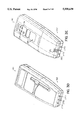
- FIG. 3D is a front, perspective view of a preferred embodiment of a recorder which docks to the docking port of the remote base unit of FIG. 3A;
- FIG. 3E is a rear, perspective view of a preferred embodiment of the recorder of FIG. 3D;
- FIG. 4 is a functional block diagram of one preferred remote base unit including its external interfaces
- FIG. 5 is a schematic diagram of an exemplary Docking Interface Board of the remote base unit of FIG. 4;
- FIG. 6 is a schematic diagram of an exemplary Recorder Interface Board of the remote base unit of FIG. 4;
- FIG. 7 is a schematic diagram of an exemplary circuit for Liquid Crystal Display of the remote base unit of FIG. 4;
- FIG. 8 is a schematic diagram of an exemplary Temperature and Scale Board of the remote base unit of FIG. 4;
- FIG. 9 is a schematic diagram of an exemplary Memory Interface Circuit of the remote base unit of FIG. 4;
- FIG. 10 is a schematic diagram of an exemplary Communications Section Circuit of the remote base unit of FIG. 4;
- FIG. 11 is a schematic diagram of an exemplary Modem Circuit of the remote base unit of FIG. 4;
- FIG. 12 is a schematic diagram of an exemplary Microprocessor Buffer Decode Circuit of the remote base unit of FIG. 4;
- FIG. 13 is a schematic diagram of an exemplary Power Supply Circuit of the remote base unit of FIG. 4;
- FIG. 14 is a schematic diagram of an exemplary Power Interface and Control Circuit of the remote base unit of FIG. 4;
- FIG. 15A is an operational flow diagram of the patient monitoring and support system of the present invention.
- FIG. 15B is the continuation of the operational flow diagram of FIG. 15A;
- FIG. 16 is a top-level flow diagram of a preferred embodiment of the software for the remote base unit shown in FIG. 4;
- FIG. 17 is a flow diagram of the data communications between the presently preferred remote base unit and the care center shown in FIG. 4;
- FIGS. 18A, 18B, 180 and 18D are flow diagrams of the data communications between the remote base unit and one of the recorders shown in FIG. 4;
- FIG. 19 is a state diagram of the Session Procedure Flow of the Perform Specified Task Function shown in FIG. 16;
- FIG. 20 is a state diagram of the Activity Help Menu Flow of the Perform Specified Task Function shown in FIG. 16;
- FIG. 21 is a state diagram of the User Initiated Testing Flow of the Perform Specified Task Function shown in FIG. 16;
- FIG. 22 is a flow diagram of an exemplary demonstration sequence of the patient monitor and support system of the present invention, configured for monitoring at-risk pregnancies.
- FIG. 1 depicts a site block diagram wherein a patient monitor and support system 50 of the present invention is configured.
- the patient monitor and support system 50 includes a number of patient sites 100 a, 100 b, 100c the total number indicated by L), which are individually connected via a set of communications links 500a, 500b, 500c to a care center 600.
- a subsystem at each of the patient sites 100 has control and data acquisition capabilities and may be configured to automatically transfer patient communications and data to the care center 600 and to receive nursing communications, instructions and prompts from the care center 600.
- the care center 600 comprises a plurality of support workstations 650a, 650b and 650c (the total number indicated by M) and a Central Database on a database computer 660.
- the workstations 650 is an IBM compatible personal computer using one of the 80 ⁇ 86 family of microprocessors.
- each patient site 100 communicates with one of the workstations 650 over a communications link 500.
- the communications link 500 may be any communications system such as a radio communications link, a modem/telephone line link, a fiber optic link or any other communications link.
- a dial-up or leased telephone line switched across the public telephone network is used and communications is established via a modem at the patient site 100 and the care center 600.
- the patients at sites 100 may also communicate by voice with the workstation 650.
- the data received by the workstation 650 is ultimately stored in the patient database computer 660.
- the care center 600 is typically connected to the facility's existing Local Area Network ("LAN") 700.
- LAN Local Area Network
- the information collected by the care center 600 is accessible from any computer on the LAN 700 and may be assimilated by existing database management software.
- the primary care physician sites 710a, 710b, 710c (the total number indicated by N) can access information collected on each patient monitored by the care center 600 via communications link 525.
- the primary care physicians at sites 710 may communicate by voice with the staff monitoring the care center 600 and with the patients at the sites 100.
- the care center 600 is staffed by a medical team comprising a case nurse, a field nurse, a pharmacist, a therapist and a nutritionist. Additional medical personnel is added as required.
- the care center 600 also has the ability to download settings and instructions to the subsystem located at each patient site 100.
- the subsystem may also be configured to alert the patient when it is time to take measurements and/or medication. It will also prompt the patient and guide them through the procedure through visual displays.
- the subsystem located at each patient site 100 is controlled by a base unit 150 as shown in FIG. 2.
- the base unit 150 is a self-contained system configured to monitor and support a specific disease state or medical condition.
- FIG. 2 is a block diagram of a preferred embodiment of the patient monitoring and support system 50 of FIG. 1 configured to monitor at-risk pregnancy.
- the base unit 150 is connected to a set of modules 110 which provide measurements of a patient's medical status.
- the base unit 150 is also connected via the communications link 500 to the care center 600.
- the communications link 500 may comprise any communications system such as a radio communications link, a modem/telephone line link, a fiber optic link or any other communications link.
- a dial-up or leased telephone line is used and communications is established via a modem 670 at the care center 600.
- sensors 120 which are directly connected to the base unit 150
- recorders 160 which receive inputs from sensors 120, record the sensor information, and transmit the recorded data to the base unit 150.
- the recorders 160 are completely portable and may be used remotely by the patient. The recorders 160 must, however, be periodically docked in the base unit 150 so as to upload or download data or instructions and to charge its batteries.
- the base unit 150 may be provided with three recorders 160 for monitoring and supporting the treatment of at-risk pregnancy.
- a combined fetal heart rate/uterine activity recorder 210, a blood pressure recorder 220 and a urinalysis recorder 230 provide measurements of fetal heart rate and uterine activity, blood pressure and urinalysis test data respectively to the base unit 150.
- the sensors associated with the recorders 160 are as follows.
- An ultrasound transducer 212 provides the means for monitoring the fetal heart rate and provides signals indicative of the fetal heart rate, to the fetal heart rate/uterine activity recorder 210.
- a tokodynamometer 214 provides the means for monitoring uterine activity and provides signals indicative of uterine activity to the fetal heart rate/uterine activity recorder 210.
- a blood pressure cuff 222 provides the means for monitoring blood pressure and provides signals indicative of the blood pressure of a patient to the blood pressure recorder 220.
- Reagent strips 232 provided to the urinalysis recorder 230 provide the required urinalysis test data.
- five types of sensors 120 may be directly connected to the base unit 150. These sensors 120 are: weight scale 122, a temperature probe 124, an event switch 126, an infusion pump 128 and a glucometer 130.
- the weight scale 122 provides a signal indicative of the patient's weight to the base unit 150;
- the temperature probe 124 provides a signal indicate of the patient's temperature;
- the event switch 126 is a manual switch provided to the patient to monitor contractions;
- the infusion pump 128 infuses medicine into the patient's bloodstream and provides signals of the quality and quantity of medicine infused into the patient's system;
- the glucometer provides signals indicative of the glucose levels in a patient's system.
- the base unit 150 may also provide signals to the infusion pump 128 to reconfigure the amount and frequency of medicine which is supplied to a patient's system.
- the sensors 120 and recorders 160 will be described in greater detail in the following sections.
- FIG. 3A is a perspective view of a preferred embodiment of the base unit 150.
- FIG. 3B illustrates the rear panel of the remote base unit of FIG. 3A.
- the unit is small and portable such that it may be placed on a table next to the patient's bed.
- the base unit 150 comprises a lid assembly 300 and a base assembly 400.
- the lid assembly 300 comprises a display assembly 310, a lid assembly board 340 (shown in FIG. 4) and two recorder docking ports 350a, 350b.
- the base assembly 400 comprises a system board 410 (shown in FIG. 4), a third recorder docking port 350c, a storage bay 440 and a rear panel 460.
- the lid assembly board 340 and the system board 410 provide the circuitry for the base unit 150 and will be described below.
- the display assembly 310 comprises a Liquid Crystal Display (“LCD”) 312 with backlight 313 capability, a touch-sensitive screen 314, a control panel 316 and three indicator lights 324, 326, 328.
- the LCD display 312 is a graphics display with a CGA resolution of 320 ⁇ 200 pixels and a viewing area of 5.04 inches ⁇ 4.33 inches.
- the touch sensitive screen 314 is capable of displaying a set of function keys (not shown), generated through software, for user selection.
- the function keys are generic and reconfigurable in software, may be selected by touching the screen 314. Up to 24 keys may be generated by software.
- the control panel 316 comprises four buttons.
- the leftmost button 317 controls power from the fluorescent backlight.
- the next button 318 controls the up contrast voltage to the LCD display 312.
- the third button 320 from the left controls the down contrast voltage to the LCD display 312.
- This second and third buttons 318, 320 are used to provide compensation for different light levels and angles.
- the rightmost button 322 is the Enter key. It is used for returning to a previous screen.
- the three indicator lights indicate the status of system.
- the leftmost indicator light 324 indicates the start of a session
- the middle indicator light 326 indicates if the power is on
- the rightmost indicator light 328 is a low battery warning indicator alarm.
- the lid assembly board 340 comprises integrated circuits for the control of the LCD 312 and touchscreen 314 of the display assembly 310. The components of the board will be discussed in greater detail in the following sections.
- the docking ports 350a, 350b, 350c on the lid assembly 300 and the base assembly 400 provide for mechanical docking of the recorders 160.
- the docking reports 350a, 350b and 350c are identical and can receive any one of the recorders 160.
- Data transfer to and from the recorders 160 and battery charging of the recorders 160 are provided through electrical and optical interfaces with the base unit 150.
- the docking port 350 is molded to accept the shape of the recorder 160, illustrated in FIGS. 3D and 3E, which is similar to that of a cordless phone cradle.
- the narrow end 162 of the recorder 160 fits into the cradle 164 of the docking port 350 and a magnet 166 in the base will contact a metal plate 168 in the middle of the recorder 160 to retain it during charging and data exchange.
- Three spring-loaded contacts 370a, 370b, 370c, at the bottom of the cradle 164 in the docking ports 350 provide the electrical and optical interface with the base unit 150.
- the contacts 370 connect to corresponding contacts 372 on the end of the recorder 160 for charging of the battery and powering the recorder 160 while the recorder 160 is docked.
- a molded projection 170 on the narrow end 162 of the recorder 160 presses against an interlock switch 178 in the base of the docking port 350 to indicate that a recorder 160 is docked.
- Four infrared components 174 at the top end of the recorder 160 allow the transmitting and receiving of data, and two of the infrared components 174 are flag channels for indicating the recorder is busy and the battery charging state.
- Four infrared components 176 in the docking port 350 correspond to and communicate with the four infrared components 174 in the recorder 160 via the infrared and power link 415 (shown in FIG. 4). When the recorder 160 is removed from the docking port 350, all power is removed from the accessible metal contacts 370, 372.
- the storage bay 440 is a cavity located in the right side of the base assembly 400. It provides storage space for sensors 120 and associated accessories required for measuring a variety of parameters. Two communications ports 443, 444 for receiving the temperature probe 124 and the event switch 126 are located in the storage bay 440.
- the rear panel 460 is an input/output interface which provides further monitoring and control capabilities for the base unit 150.
- the rear panel 460 comprises a power switch 462 and a plurality of connectors.
- the power switch 462 permits the powering on and off of the base unit 150.
- the first connector 466 provides for connection from an external 16 volt DC supply.
- the second connector 468 provides connection to a sensor.
- a DB-9 connector is used, which accepts bi-directional data from the infusion pump 128.
- the third connector 466 provides connection to a second sensor.
- the connector is preferably a DB-9 connector which accepts data from a glucometer 130.
- the fourth connector 470 accepts an analog signal from the weight scale sensor 122 and provides power to the load cells in the scale 122.
- the fifth connector 472 is provided for connection to a printer 136 which prints fetal heart rate/uterine activity charts.
- the sixth connector 474 is a direct connect port 474.
- the port is preferably a conventional RS-232 type port, provided to permit the base unit 150 to be connected directly to another personal computer 138 for testing and data retrieval.
- the seventh connector 476 provides for connection to a telephone line 134.
- the connector is an RJ-11 jack, which provides for direction connection to the public switched telephone network.
- the eighth connector 478 provides for connection to a telephone line 134.
- a RJ-11 connector is used, which accepts a standard telephone and provides a connection to the telephone line 134 when the modem 670 is not on-line.
- FIG. 4 is a functional block diagram of an exemplary base unit 150 and the modules 110 (sensors 120 and recorders 160) and care center 600 with which it interfaces.
- the base unit 150 communicates with the care center 600 from remote sites 100.
- the sensors 120 are connected to the remote base unit (RBU) 150 via connectors 464, 466, 468, 470, 472, 474, 476 and 478 on the rear panel 460 of the RBU 150 and via connectors 443 and 444 located within the storage bay 440 of the RBU 150.
- the recorders 160 communicate with the RBU 150 via infrared and power links 415.
- These connectors 443, 444, 464, 466, 468, 470, 472,474,476 and 478 and infrared links 415 provide the signals from the sensors 120 and recorders 160 to the electronics circuitry in the RBU 150.
- the RBU 150 comprises a lid assembly 300 (shown in FIG. 3) and a base assembly 400 (shown in FIG. 3).
- the lid assembly 300 comprises a display assembly 310, a lid assembly board 340 and two recorder docking ports 350a, 350b.
- the base assembly 400 comprises a system board 410, a third recorder docking port 350c, a storage bay 440 and a rear panel 460.
- the lid assembly board 340 comprises integrated circuits for the control of the LCD 312 and touchscreen 314 and two recorder interface boards 416a, 416b.
- the system board 410 comprises a recorder interface board 416c, a microprocessor-based central processing unit (CPU) 412, a memory module 418, a temperature/scale board 420, a memory interface circuit 430, a communications interface circuit 440, a modem board 450, a microprocessor decode buffer circuit 461, three power supplies 471a, 471b, 471c and a power interface and control circuit 480.
- CPU central processing unit
- the memory module 418 connected to the CPU 412 via a conventional data bus, comprises 64 Kbytes of Read Only Memory (ROM) used for the Basic I/O System (BIOS), 1 Megabyte of ROM used for the operating system and applications software and up to 32 Megabytes of Random Access Memory (RAM).
- ROM Read Only Memory
- BIOS Basic I/O System
- RAM Random Access Memory
- the fetal heart rate/uterine activity recorder 210, the blood pressure recorder 220 and the urinalysis recorder 230 are each connected using infrared and power links 415a, 415b, 415c via the docking interface boards 414a, 414b, 414c in each recorder 210, 220, 230 to one of two recorder interface boards (RIBs) 416 on the Lid Assembly 300 or to the recorder interface board 416 on the base assembly 400.
- Information previously recorded by the recorders 210, 220, 230 are then transferred to the CPU 412.
- the patient takes the required measurements and the recorders 210, 220, 230 store the information, which is transferred to the CPU 412.
- the five directly connected sensors are connected to the RBU as follows.
- the weight scale sensor 122 is plugged into connector 470 in the rear panel 460 of the RBU 150.
- the infusion pump 128 and the glucometer 130 are plugged into either connector 466 or connector 468 on the rear panel 460 of the RBU 150.
- the temperature probe 124 and the event switch 126 are plugged into the receptacles 443 and 444 located within the storage bay 440 of the base assembly 400.
- the measurements monitored by the temperature probe 124 and weight scales 122 are provided to the temperature/scale board 420, which processes the signals provided by the temperature probe 124 and weight scales 122.
- the resultant signals are provided via the communications interface circuit 440 to the CPU 412.
- Signals provided by the event switch 126 via event receptacle 444 are provided to an I/O port decode circuit 820, in the communications interface circuit 440 which provides proper selection of the I/O ports to be read.
- signals provided by the glucometer 130 and infusion pump 128 via connectors 466, 468 are first provided to electromagnetic interference/electromagnetic static discharge (EMI/ESD) circuits 832, 834 which filter the signals from extraneous electromagnetic radiation.
- EMI/ESD electromagnetic interference/electromagnetic static discharge
- the signals from the I/O port decode circuit 820 and the EMI/ESD circuits 832, 834 are provided to the interface circuit 445, which permits the CPU 412 to select the device it communicates with.
- the device is either the event switch 126, glucometer 130 or infusion pump 128.
- the resultant signals are provided to the microprocessor decode buffer circuit 461, which then provides the signals to the CPU 412.
- the external power supply 132 is provided to the power supply interface and control circuitry 480 via power connector 464.
- the power is provided via the microprocessor decode buffer circuitry 461 to the other elements in the RBU 150.
- the telephone line 134 is provided via an RJ-11 connector 478 to the internal modem circuitry 450 of the RBU 150.
- a portable printer 136 for printing fetal heart rate/uterine activity charts, is connected via connector 472 to the CPU 412 and then to the modem 450.
- a computer 138 for testing and data retrieval may be connected via a direct connector 474 to the CPU 412 and then to the modem 450.
- FIG. 5 is a schematic diagram of an exemplary docking interface board (DIB) 414 in each of the recorders 160.
- the DIB 414 comprises four infrared circuits 702, 704, 706, 708, a battery charge control circuit 712, and a battery charge ESD protection circuit 714.
- two circuits 702, 704 are dedicated for receiving and transmitting data, respectively.
- the other two circuits provide two flag channels 706, 708 used for indicating that the recorder 160 is busy and for indicating the battery charging state of the recorder 160 and docking port 350, respectively.
- three spring-loaded contacts at the bottom of the cradle in the docking ports 416 provide the electrical and optical interface with the RBU 150.
- the contacts connect to corresponding contacts on the end of the recorder case for charging of the battery and powering the recorder 160 while the recorder 160 is docked.
- the battery charge controller 706 coordinates the charging of the battery in the recorder 160.
- the battery charge ESD protection circuit 722 isolates the board from extraneous ESD.
- the battery cells in the DIB 414 are charged by a battery pack in the RBU 150 via connector 716.
- the battery cells permit the recorder to record measurements remote from the RBU 150.
- Connector 718 provides for connection to the LCD 312.
- a second connector 720 provides a means for supplying power to the components on the DIB 414.
- these connectors are Molex connectors.
- An ambient light chopper and controller 722 ensures that ambient light does not interfere with the functioning of the infrared sensors.
- FIG. 6 is a schematic diagram of an exemplary recorder interface board ("RIB") 416 of the RBU 150 diagrammed in FIG. 4.
- the RIB 416 comprises four infrared circuits 732, 734, 736, 738, a light beam interrupt sensor 740 and an LED power charge indicator 326.
- Two of the circuits 732, 734 provide channels for transmitting and receiving data, respectively, from the recorders 160 and two flag channels 736, 738, for indicating the RBU 160 is busy and in a battery charging state, respectively. These four channels correspond to the four infrared channels on the DIB 414 (FIG. 5).
- the LED 326 on the RIB 416 provides indication of the power charging state of the RBU 150 and a light beam interrupt sensor 740 indicates the presence of a docked recorder 160.
- FIG. 7 is a schematic diagram of an exemplary Lid Assembly Board 340 of RBU 150 diagrammed in FIG. 4.
- the LCD Assembly Board 340 comprises an EPSON E 1330DA LCD display controller chip 750 which controls the LCD display 312 and touch screen 314 decoding functions, as well known in the art.
- the LCD controller 750 is provided with volatile Random Access Memory (“RAM”) 750 for screen bit mapping and a Read Only Memory (“ROM”) 750 for character generation.
- RAM Random Access Memory
- ROM Read Only Memory
- a Peripheral Interface Adapter (PIA) 752 connected to the controller chip 750, is used to provide the interface with the touch sensitive screen 314. These components are well known in the art.
- the LCD screen brightness and contrast control voltages are provided by a digital rheostat 754 which is controlled by a pair of switches 318, 320 mounted on the front control panel 316 of the lid assembly 300.
- the rheostat 754 is a DS 1669-50 digital rheostat.
- the lid assembly board 340 also has an LED power supply 756 which supplies power for the up/down contrast voltage controlled by buttons 318, 320 on the control panel 316 and a backlight power supply 758 controlled by the button 317.
- the lid assembly board 340 also provides connectors 760 for the system board's input/output (I/O) bus and annunciator signals (power on, low battery and Scheduled Appointment Reminder Indicator (SARI)).
- I/O input/output
- SARI Scheduled Appointment Reminder Indicator
- the matrix pullups circuit 762 and the matrix drivers circuit 764 identify the area of the touch screen 314 the area has selected, as known in the art.
- a decode latches circuit 768 enables data to be saved, as known in the art.
- FIG. 8 is a schematic of the temperature and scale board 420. It comprises an analog-to-digital converter (ADC) 770, temperature signal procession 772 and a weight scale signal processor 774. As shown in FIG. 8, the ADC 770 accepts analog inputs from multiple channels. In the present embodiment, the ADC 770 accepts inputs from 3 channels. The low voltage sense signals from the RBU 150 enter the ADC 770 which converts the sense signals to digital form upon request by the CPU 412. The digitized values are read by the CPU 412 via a conventional data bus connecting the ADC 770 to the CPU 412.
- ADC analog-to-digital converter
- the temperature scale signal processor 772 is connected to an external temperature probe 124 (FIG. 4) via a connector 443 in the storage bay 440, and comprises a temperature probe presence detect signal line 776, an autocalibration circuit 778, a gain and offset circuit 780 and a filter 782.
- the temperature probe 124 is plugged into the connector 443
- the temperature presence detect signal line 776 which is read by the CPU 412 (FIG. 4)
- a second signal is concurrently provided by the probe 124 to an autocalibration circuit 778, which calibrates the scale to be used in measuring the incoming signal. Calibration is performed by the software.
- the gain and offset circuit 780 then amplifies the signal from the temperature probe 124 so as to correspond to the range of the ADC 770, and offsets the signal to take full advantage of the ADC's range.
- the signal is then filtered through filter 782 to eliminate random noise and then provided to the ADC.
- the CPU 412 will then read the output of the ADC 770.
- the weight scale signal processor 774 is also connected to an external weight scale 122 (FIG. 4), via connector 470.
- the processor 774 comprises a scale presence detect signal line 784, a scale gain potentiometer 786, a gain and offset circuit 788 and a filter 790.
- the scale presence detect signal line 784 detects the presence of an external scale 122 in the same manner as the temperature probe 124 presence detect signal line 776.
- a second signal provided by the scale 122 is concurrently provided to the scale gain potentiometer 786, which sets the signal range for proper digitization for the ADC 770. The signal is then provided to a gain and offset circuit 788.
- the gain and offset circuit 788 then amplifies the signal so as to correspond to the range of the ADC 770, and offsets the signal to take full advantage of the ADC's range.
- the signal is then filtered via filter 790 to eliminate random noise and then provided to the ADC 770.
- the CPU 412 will then read the output of the ADC 770.
- FIG. 9 illustrates the Memory Interface Circuit 430 of the RBU 150 diagrammed in FIG. 4.
- the Memory Interface Circuit 430 comprises an address bus buffer 792, a boot microprocessor decoder 794, a ROM BIOS Hook 796, a data decoder 798, a run decoder 799, a data bus buffer 800, a memory module with 4 sets of memory 418a, 418b, 418c, 418d and a programmable configuration change circuit 810.
- the memory module 418 connected to the CPU 412 (FIG. 4) via a conventional data bus, comprises 64 Kbytes of Read Only Memory (ROM) used for the Basic I/O System (BIOS), 1 Megabyte of ROM used for the operating system and applications software and up to 32 Megabytes of Random Access Memory (RAM).
- ROM Read Only Memory
- BIOS Basic I/O System
- RAM Random Access Memory
- Signals from the CPU 412 are provided to the address bus buffer 792 which provides a boost to signal strength along the address bus.
- the address bus buffer 792 then provides the signals to the boot microprocessor decoder 794 which decodes ROM addresses and enables the ROM BIOS hook 796.
- the ROM BIOS hook 796 provides a mechanism for allowing the software to be executed during the boot-up process.
- the signals are then provided to the data bus buffer 800 which ensures that the memory circuits are adequately driven and the programmable configuration change circuit 810 permits changes in configuration to be implemented. These signals are then provided to the memory modules 418 which reside on the same circuit board as the memory interface circuit 430.
- Signals from the CPU 412 are also provided to the data decoder 798 which provides selection of the correct channels. These signals are then provided to the run decoder 799 which coordinates signal flow. Signals from the run decoder are then provided to the data bus buffer 800, which functions as described above and which provides the signals to the memory modules 418. Signal flow between the CPU 412 and the memory modules 418 via the memory interface board 430 is bi-directional. The components described above are well understood in the art.
- the Communications Interface Board 440 comprises an I/O Port Decode Circuit 820 implemented by two Universal Asynchronous Receiver/Transmitters 822, 824 (UART) as known in the technology.
- UART Universal Asynchronous Receiver/Transmitters 822, 824
- the UART provides clear-to-send and request-to-send processing used for data flow control.
- Multiplexers 826, 828 connected to each of the UARTs 822, 824 select microprocessor communication with communications ports 446, 448 and the event switch receptacle 444.
- the multiplexer 828 is connected via RS232 converter 830 which converts RS 232 voltages to transistor-to-transistor (TTL) voltage levels, as known in the art.
- TTL transistor-to-transistor
- the RS 232 converter 830 is connected to two EMI/ESD circuits 832, 834.
- the EMI/ESD circuits 832, 834 filter extraneous electromagnetic signals from the circuits and are connected to communications ports 4
- the Hardware Watchdog Alarm 836 connected to the CPU 412 forces a system reset if the system is not triggered at a predetermined interval, as known in the technology.
- the predetermined interval is 30 seconds and serves to conserve power.
- the system reset is also announced by a 200 millisecond beep from a small piezoelectric speaker.
- FIG. 11 depicts the Internal Modem Circuit 450 of the RBU 150.
- One serial interface of the communications interface circuit 440 is used to communicate to an internal modem 450, which in turn connects to a telephone line 134 (FIG. 4) via phone jack 478 to communicate with the care center 600.
- the internal modem 450 is a Hayes-compatible integrated circuit 840 which provides 2400 baud modulation and demodulation for direct telephone line connection.
- the serial interface is used to communicate to a radio interface (not shown) which in turn connects to a radio (not shown) to communicate with the care center 600.
- a radio interface not shown
- a radio not shown
- the internal modem circuit 450 also has a ring detect circuit 842 which indicates when a message is received. Finally, the circuit 450 has a line interface circuit 844 which provides the necessary interface from the modem circuit 840 to the connector 478 and the ring detect circuit 842.
- FIG. 12 is a schematic diagram of the Microprocessor Buffer Decode Circuit 461 of the RBU 150 diagrammed in FIG. 4.
- This circuit provides a buffer for the CPU 412 and permits the CPU 412 to select the device it is reading from or to.
- the microprocessor of the CPU 412 fits into the connector 850 on the microprocessor buffer decode circuit 461.
- the connector connects to a microprocessor buffer decode circuit 852 which provides a buffer for the CPU 412 as known in the art.
- the buffer decode circuit 852 is connected to flex cables 854 which connect the base assembly board 410 to the lid assembly board 340.
- the communications interface circuit 858 connects the direct connector 474 to the CPU 412 and the ESD/EMI circuit 860 connects the printer connector 472 to the CPU 412.
- three identical power supplies each provide +8.75 volts DC to power each of the recorders 210, 220, 230 for data communications and operation.
- An additional lead 862a, 862b, 862c in each of the power supplies 471a, 471b, 471c provide a 600 mA constant current source to charge the battery pack.
- the power supplies 471a, 471b, 471c additionally controls the shutdown interlock via connections 864a, 864b, 864c.
- the Power Interface and Control Circuitry 480 provides an interface to external power and circuitry for control and monitoring of power.
- An external source 132 provides the +16 volts DC to the RBU's I/O bus via power connection 462. From the external power source 132, the control circuitry 870 derive +5 volts DC power necessary for other elements in the RBU 150.
- the control circuit 872 derives power for the LCD backlight 313 and the indicator lights 324, 326, 328.
- a separate battery-backed RAM 874 is provided to retain memory during power loss. Presently, nickel-cadmium batteries are used.
- the power interface and control circuit 480 also has a shutdown circuit 876 which shuts down the system in the event of a catastrophic circuit failure and a low power shutdown circuit 878 which provides for power shutdown when the battery voltage falls below the limit required for normal operations.
- two types of modules 110 may be connected into the RBU 150: sensors 120 which may be plugged directly into the RBU 150, and recorders 160, which receive inputs from sensors 120, record the sensor information, and transmit the inputs to the RBU 150.
- the recorders 160 are completely portable and may be used remotely by the patient. The recorders 160 must however, be periodically placed into a docking port 350 in the RBU 150 so as to upload or download data or instructions and to charge its batteries.
- the RBU 150 is configured to receive three recorders 210, 220, 230 for monitoring a the medical status or condition of a patient.
- the medical condition monitored is an at-risk pregnancy.
- the recorders utilized to monitor this condition are: a combined fetal heart rate/uterine activity recorder 210, a blood pressure recorder 220 and a urinalysis recorder 230.
- the fetal heart rate/uterine activity recorder 210 is a hand-held, completely self-contained ultrasound fetal heart rate monitor with uterine activity and event channels.
- the fetal heart rate/uterine activity recorder comprises a docking interface board (DIB) 414 and a fetal heart rate/uterine activity circuit board (not shown).
- the DIB 414 comprises four infrared channels which provide logic levels to indicate that the recorder is busy with a measurement, to indicate that the battery pack is 10 degrees C above ambient (indicating full battery charge) and the third and fourth channels are used to transmit and receive data as discussed above.
- An intrauterine sensor 214 is connected to the fetal heart rate/uterine activity board via a connector.
- a tokodynamometer as claimed in pending U.S. patent application Ser. No. 07/754,960 and assigned to the assignees of the present invention is preferably used as the intrauterine sensor 214 and is connected to the uterine activity recorder via a connector.
- the fetal heart rate/uterine activity circuit board is model number 4220 provided by Seward Medical Ltd. in Newport, Wales.
- An ultrasound transducer 212, model 4220 provided by Seward Medical Ltd. is also connected to the fetal heart rate/uterine activity circuit board via a connector.
- the ultrasound transducer 212 monitors the fetal heart rate and provides the fetal heart rate to the fetal heart rate/uterine activity circuit board.
- the fetal heart rate/uterine activity circuit board utilizes continuous doppler shift ultrasound technology, as known in the relevant technology, to provide the fetal heart rate signals on the LCD 312 of the RBU 150.
- the fetal heart rate may be detected via headphones connected to the fetal heart rate circuit board.
- a programmable timer in the fetal heart rate/uterine activity circuit board controls the monitoring session length and overall exposure time to ultrasound energy.
- the fetal heart rate/uterine activity recorder 210 is docked in the RBU 150 and the LCD 310 in the RBU 150 prompts the patient through the set-up procedure and monitoring session. Various warning prompts and an audible beeper alerts the patient to any problems during the session.
- the blood pressure recorder 220 comprises an DIB 414 and a blood pressure circuit board.
- the DIB is substantially similar to the DIB described above.
- the blood pressure circuit board is model number 90207 provided by Spacelabs Medical Inc. from Redmond, Wash.
- a blood pressure cuff 222 with a pressure transducer is connected to the blood pressure recorder 220 and used to monitor blood pressure.
- One of four blood pressure cuff sizes may be selected, and these are model numbers SAD 4211, AD 4212, LAU 4213 and EXL 4214 provided by Spacelabs Medical Inc.
- the blood pressure recorder 220 is a battery-operated microprocessor-controlled non-invasive pressure monitor. The blood pressure recorder 220 automatically inflates and deflates a range of pressure cuffs described above.
- the blood pressure recorder 220 has two modes of operation: an ambulatory mode, where the patient wears the cuff 222 for an extended period and the RBU 150 automatically takes readings and a reminder mode where the unit alerts the patient that it is time for a reading.
- the blood pressure recorder 220 is placed in one of the RBU's docking ports 350 to charge its batteries and transfer its data.
- the RBU 150 may also reset the controls in the blood pressure recorder 220.
- the urinalysis recorder 230 used in the present embodiment is disclosed in U.S. Pat. No. 5,182,707 assigned to the assignee of the present invention and is hereby incorporated by reference.
- the urinalysis recorder 230 additionally comprises an DIB 414 which is substantially identical to DIB 414 described above.
- the urinalysis recorder 230 is a battery-operated microprocessor-controlled device that permits a patient to visually match the results of a urine reagent strip 232 with color blocks printed on the top of the recorder 230. Each record is time and date stamped and stored in memory. When the urinalysis recorder is returned to the RBU 150, the data will be transferred to the RBU memory 418 via the infrared link 415.
- the LCD display 312 is employed to prompt the patient through the measurements. Additionally, the front panel overlay on the urinalysis recorder 230 can be changed to accommodate different combinations of reagent test pads.
- the sensors 110 which are directly plugged into the RBU 150 to monitor at-risk pregnancy are: a temperature probe 124, a weight scale 122, an infusion pump 128, an event switch 126 and a glucometer 130.
- the temperature probe 124 is of the thermistor variety.
- the thermistor is located at the end of a four-inch long shaft encased in an aluminum tube.
- the tip is isolated from the rest of the shaft via a plastic separator section with the rest of the shaft made of stainless steel.
- the opposite end of the shaft has a molded plastic grip that will also provide a cable strain relief.
- the cable connected to the probe is a three feet long coiled cord terminated at a connector that mates with the connector in the storage bay.
- the weight scale 122 used in the present embodiment is a platform which connects via cable to the rear panel 460 of the RBU 150.
- the presently preferred scale utilizes a four load cell configuration for a measuring a maximum weight of 440 pounds, ⁇ 0.5 pounds.
- the platform is preferably covered with a molded plastic housing and provided with a bottom plate to protect the load cells. In the present embodiment, the platform is 11" ⁇ 13" ⁇ 2".
- the infusion pump 128 used in the present embodiment is model 508 manufactured by Mini-Med Inc. of Sylmar, Calif.
- the infusion pump 128 contains a data interface and may be connected to serial ports 466 or 468 on the rear panel 460.
- the infusion pump 128 may be reprogrammed from the care center 600 and medical information stored in the pump's internal memory may be uploaded from the pump 128 to the care center 600.
- the patient In the at-risk pregnancy configuration, the patient may, for example, be infused with trebutaline under certain conditions.
- the event switch 126 used in the present embodiment is model 4201 manufactured by Switchcraft Co.
- the event switch 126 is mounted in a hand-grip housing with a thumb button at one end and six feet of cable at the other end.
- the event switch 126 provides a means of counting the kicks of the fetus when the fetal recorder 210 is not included with the system.
- the event switch 126 may be reconfigured to monitor the occurrence of any event.
- the glucometer 130 utilized in the present embodiment is model PVD manufactured by Miles Diagnostic Inc. of Illinois.
- the glucometer 130 contains a data interface and is connected to either serial ports 466 or 468 on the rear panel 460 of the RBU 150.
- the results of the glucose measurements stored in the glucometer's internal memory is transferred into the memory of the RBU 150 and subsequently transmitted to the care center 600.
- the RBU 150 may also be reconfigured to monitor a variety of other medical conditions or therapies. These conditions may be monitored in conjunction with at-risk pregnancy to provide a more complete treatment tailored to a patient's particular needs. Alternatively, the RBU 150 may be configured to monitor other specific medical therapies for the treatment of specific medical conditions.
- FIGS. 2 and 4 The following sections will continue to refer to FIGS. 2 and 4 in discussing: A. Monitoring of Human Organ Flow; B. Monitoring of In Vivo Plasma Separation; C. Monitoring of Blood Cholesterol Exchange; and D. Monitoring of Gas Exchange. It should be noted that the RBU 150 may be similarly reconfigured to monitor other disease states.
- the RBU 150 may be reconfigured to monitor human organ flow. Treatment of various disease states, such as kidney failure or liver failure, requires therapy involving the monitoring of fluid flow.
- the RBU 150 may be reconfigured to monitor kidney dialysis.
- a kidney dialysis recorder may be used in place of one of the recorders 160 described above for a patient with an at-risk pregnancy condition, or used in conjunction with fetal heart rate/uterine activity recorder 210, the blood pressure recorder 220, and urinalysis recorder 230.
- kidney dialysis apparatus disclosed in U.S. Pat. No. 5,151,082 and assigned to the assignee of the present invention, which is hereby incorporated by reference, may be used in place of one of the recorders 160.
- this kidney dialysis recorder additionally comprises an DIB 414, which is substantially identical to the DIB 414 described above, and which is used to facilitate data communications with the RBU 150.
- the RBU 150 may also be reconfigured to monitor liver support.
- a liver support recorder may be used in place of one of the recorders 160 described above or used in conjunction with the blood pressure recorder 220, and urinalysis recorder 230 or any other recorder 160.
- this liver support recorder additionally comprises an DIB 414, which is substantially identical to the DIB 414 described above, and which is used to facilitate data communications with the RBU 150.
- the kidney dialysis recorder and the liver support recorder may also be reprogrammed from the care center 600.
- Such reprogramming includes updated treatment schedules and updated medical procedures which reflect changes in the treatment of kidney dialysis. Medical information stored in the kidney dialysis recorder's memory and that stored in the liver support recorder's memory may be uploaded from the respective recorders 160 to the care center 600.
- the recorder 160 for monitoring in vivo plasma separation is disclosed in U.S. Pat. No. 4,950,224, assigned to the assignees of the present invention and hereby incorporated by reference.
- the recorder additionally comprises an DIB 414 as described above and is docked in the recorder docking port 350 in the same manner as the recorders 160 described above.
- a catheter as claimed and described in pending U.S. application Ser. No. 07/229,138, assigned to the assignees of the present invention, and hereby incorporated by reference, is used to connect the recorder to the patient's vein.
- the RBU 150 may also reconfigure the settings of the in vivo plasma separation recorder.
- the recorder 160 for monitoring blood cholesterol exchange is disclosed in U.S. Pat. No. 5,152,743, assigned to the assignees of the present invention and is hereby incorporated by reference.
- this recorder additionally comprises an DIB 414 as described above, to facilitate data transmission with the RBU 150.
- a catheter as claimed and described in pending U.S. application Ser. No. 07/229,138, assigned to the assignees of the present invention and hereby incorporated by reference, is used to connect the recorder to the patient's vein.
- the recorder is docked, and information between the recorder and the RBU 150 is transmitted and received in the same manner as for the recorders described above.
- the RBU 150 may also reconfigure the settings of the in blood cholesterol exchange recorder.
- the recorder 160 for monitoring gas exchange is disclosed in pending U.S. patent application Ser. No. 07/745,912, assigned to the assignees of the present invention and hereby incorporated by reference.
- this recorder additionally comprises a DIB 414 as described above.
- a catheter as claimed and described in pending U.S. application Ser. No. 07/229,138, assigned to the assignees of the present invention and hereby incorporated by reference, is used to connect the recorder to the patient's vein.
- the recorder is docked, and information between the recorder and the RBU 150 is transmitted and received in the same manner as for the recorders described above.
- the RBU 150 may also reconfigure the settings of the in gas exchange recorder.
- FIG. 15 is an operational flowchart of the patient monitoring and support system 50 of the present invention.
- the RBUs 150-150C acquire data representing the medical status and requirements of a patient and transmits the data to the care center.
- the care center 600 performs primarily the functions of obtaining data from the RBUs 150-150C and for communicating with the RBUs 150-150C.
- the care center 600 also accepts inputs from medical personnel monitoring the status of the patients at the care center 600 or from primary care physicians 710 on the LAN 700 and transfers the data to the RBU 150. It can also reconfigure the RBUs 150 based on the input provided at the care center 600.
- the primary care physician 710 or medical personnel from a clinic or hospital initially supplies individual patient history including surgery and/or therapy, the patient's medical status and symptoms to the care center 700 staff. Based on the patient's history and medical status, the doctor prescribes home care. The patient's personal data is entered into the database at the care center 600.
- the doctor and staff consults with each other and the doctor provides a prescription of the required therapy or treatment as shown in block 884.
- the care center staff constructs a regimen initially tailored for the patient. These include system configuration, the definition of protocols, developing a report of the structure, configuring the system and validating the system.
- the care center staff comprises a field nurse, a case nurse, a nutritionist, a therapist and other medical support personnel.
- the system When the regimen is properly constructed, the system is delivered and installed in the patient's home as shown in state 886. Upon installation, a member of the care center staff trains the patient monitoring and status system 50 of the present invention, as shown in state 888.
- the patient When training is completed, the patient is ready to operate the system as shown in state 890.
- the medical data obtained is sent as depicted in state 892, to the care center staff who enters the data into the database, as shown in state 894.
- the staff then prepares the necessary physician reports and transmits them to the physician as shown in state 896.
- the physician Upon receipt of the data, the physician interprets and analyzes the data as shown in state 900. Based on the physician's analysis, the care center staff calculates, orders, delivers drugs or supplies and schedule nurse visits as required, as shown in state 902. These instructions are sent to the patient.
- the patient's prescription, visits and schedules are changed as shown in state 904.
- the care center staff accordingly changes the configuration, protocols, etc., according to the new prescription via modem.
- the patient receives the changes and implements the changes via modem or manually.
- state 904 If configuration is required, the process in state 904 is repeated. If no configuration is necessary, operation of the system (state 890) is reinitiated and further therapy is obtained (state 908), otherwise, the session is terminated at state 910.
- FIG. 16 is a flow diagram of the at-risk pregnancy monitoring and support software of the present invention, which is located in the remote base unit 150.
- Software for the base unit 150 function is, in a presently preferred embodiment, written in the "C++" language.
- the software described herein, which is listed in the attached Microfiche Appendix, was translated from the source code into object code using a Borland "C++" compiler. Nonetheless, one skilled in the technology will recognize that the steps in the accompanying flowcharts can be implemented by using a number of different languages, language translators, computers and circuitries.
- the RBU 150 comprises a microprocessor such as the AMPRO XT (CPU 412, FIG. 4) which executes a computer program.
- the computer program controls the operation of the system.
- At the start of the program (state 912) initialization of variables, program data and device registers occurs.
- Global variables which are common variables used by more than one function and/or object in the program are first initialized, as shown in state 914.
- the state machine is then initialized, as shown in state 916. This is a definition of process structure and starting point.
- vendor communication is initiated at state 918. This is an initialization of the routines in communications software obtained from a third party; which make use of the modem and serial ports for data communications with the care center 600, the recorders 160 and other peripherals.
- the Read Configuration file used to configure registers for the session program input/output is then initialized (state 920).
- hardware objects such as LCD control are initialized (state 922), followed by Interface objects (state 924) and Test Configuration (state 926) such as calibration settings. These are the software routines which control the hardware, interface data and test data.
- Patient Data includes the name, Patient identification, phone number of primary physician and care center and a list of their scheduled sessions.
- the Event Schedule which handles the multitasking of the software objects is next initialized (state 930).
- Initialization of the User Interface Data follows (state 932). This includes initialization of Error Handling format, the Icon Manager and the System Input and Output.
- the Hardware Input/Output registers are next initialized (state 934). These include initialization of the port and docking detects, the light indicators, the battery check register, the recorder charging register and the watchdog register.
- Session Manager schedules the sessions and updates all sessions displayed on the machine. Sessions here refer to the scheduled periods during which the patient monitors his medical condition. Variables in the Home Display are then initialized (state 938).
- the program queries if the QUIT flag, a variable stored in RAM, is set as shown in state 940. If the flag is set, the program proceeds to delete the previously initialized values as shown in states 955-976. If the QUIT flag is not set, the program proceeds to the next state, state 942, which retriggers the hardware watchdog alarm. This process prevents the computer from being reset, and permits the program from continuing without interruption. The program then proceeds to examine if the program state is idle as shown in state 946. This state examines the reasons for inactivity.
- state 948 checks if there has been a system input by examining if a touchscreen 314 function key on the LCD 312 has been selected. The program also checks with the scheduler to examine if a session is scheduled. If either a key has been selected or a session has been scheduled, the program requests performance of the specified task as shown in state 954. For example, a session may be initiated, measurements such as blood pressure are taken and the data is transmitted from the base unit 150 to the care center 600. The human interface portion of the base unit 150 software will be described in some detail below with respect to FIGS. 18 to 22. If neither of these activities occurred, the program proceeds to examine if the program state is still idle as shown in state 950.
- the program checks the test battery, the session controller and the recorder docking bays to see if a recorder is docked, it then updates the time clock, coordinates the charging of the recorder. If all these activities are not in error, the program returns to state 950 and checks if the base unit 150 is still idle. When the base unit 150 is no longer idle or if an error has been corrected, it proceeds to perform the task as specified by the patient or as scheduled (state 954).
- the program checks the QUIT flag (state 940) and continues examination of the program state and performance of the specified tasks until request for termination is made. When termination of the program is requested, deletion of previously initialized values are deleted (states 955-976). Finally, the program examines if the restart flag is set as shown in state 980. If so, the program starts up again (state 982). If not, the program is terminated (state 984).
- the care center 600 functions as the system controller in the present embodiment and performs the following primary functions: poll the remote base units ("RBUs") 150 (FIG. 2) for data, provides the data received to a member of the medical staff, stores information obtained from the RBUs 150 in a central database managed by or maintained on the facility's patient database computer 660 (FIG. 1), transmits information such as instructions, medical procedures and scheduling of appointments to the RBUs 150.
- RBUs remote base units
- FIG. 1 the care center 600 functions as the system controller in the present embodiment and performs the following primary functions: poll the remote base units ("RBUs") 150 (FIG. 2) for data, provides the data received to a member of the medical staff, stores information obtained from the RBUs 150 in a central database managed by or maintained on the facility's patient database computer 660 (FIG. 1), transmits information such as instructions, medical procedures and scheduling of appointments to the RBUs 150.
- a South Mountain Communication Board with 8 channels is used.
- the patient database computer is preferably a VAX
- the care center 600 is typically connected to the facility's existing Local Area Network ("LAN") 700.
- LAN Local Area Network
- This facility may be a hospital, a service center or a clinic.
- One example of the LAN system is the Novell Operating System.
- the information collected by the care center 600 is accessible from any workstation 650 on the LAN 700.
- the primary care physician located at the remote site 710 can access information collected on each patient monitored by the care center 600.
- Data transmission from the RBU 150 to the care center 600 is initiated in one of three ways.
- the second technique is represented by state 992 in FIG. 17.
- the RBU 150 constructs a temporary output file or output files for transmission on the RAM drive, as shown in state 994.
- the RBU 150 then calls the care center 600 via the communications link 500 previously described and connects with the care center 600 as depicted in state 996. All available data is then transmitted by the RBU 150, as shown in state 998.
- Each session will be sent as a separate file with specific names. Examples of files that are sent are patient identification, data identification # where "TP" represents tocolytic data, "FH” represents fetal heart rate and "FA” represents fetal assessment.
- the "#" sign represents the characters 0 through 9 or A through F, which represent the hexadecimal value of the session number.
- a "trigger" file is sent, as depicted in state 1002.
- This file triggers the care center 600 to take an action.
- the RBU 150 transmits a dummy file to the care center 600 to indicate that it is ready to receive files from the care center 600.
- the RBU 150 then indicates the end of its transmit phase, as illustrated in state 1004.
- the RAM drive files such as session data, are then temporarily deleted.
- the care center 600 Upon receipt of the "trigger" file, the care center 600 prepares to transmit data to the RBU 150.
- the care center 600 first interrogates its data base (state 1006) to determine if there has been any change in patient configuration requiring an update of the RBU 150, as shown in state 1008. If no change is required, the care center 600 proceeds to transmit the time and date, as shown in state 1014. If there is a change in patient configuration, updated files are transmitted, as indicated in state 1010. Basically, the care center 600 transmits all pertinent files to update the RBU's configuration.
- the RBU 150 receives these files as temporary files and stores them on the RAM drive (state 1012).
- the care center 600 then proceeds to send its current time and date, as indicated in state 1016.
- the end of the care center 600 transmit phase is then indicated (state 1016) and the call is terminated through issuing of hangup commands by both the RBU 150 and the care center 600, as depicted in state 1018.
- the RBU 150 Upon termination of the call, the RBU 150 updates its time clock from data received from the care center 600 (state 1020). File management in the RBU 150 then takes place at state 1024. If data transmission was successful, all measurement data files are deleted. If file reception was successful, the received files are distributed to the addressed locations. The remaining received files are then deleted. The RBU 150 then tests if any patient configuration, such as test schedules, medical procedures,etc., has changed (state 1026). If not, the present sequence ends and normal patient monitoring resumes (state 1030). If patient configuration has changed, the RBU 150 reboots itself, as indicated in state 1028. Upon rebooting, the present sequence ends and normal patient monitoring resumes (state 1030).
- patient configuration such as test schedules, medical procedures,etc.
- the design of the files structures for the RBU is based on C++ computer language.
- the source code is used by both receiving and transmitting programs. All data is stored in separate files on the RBU. Each measurement taken is appended to a file named for the measurement, for instance, weight data, temperature date, etc. All data storage files consists of the data records only, without file headers or data header lines.
- Each session of waveform data collection is stored in separate files on the RBU with a daily session number as part of the extension. All data storage files consists of the Data Headers and Data Records only. At the time for transfer of data, this data is prefixed with the File Header data and transmitted as separate files. Individual data structures or records have comma delimited fields, except for the waveform data itself, and carriage return delimited records, with all data initially in ASCII for development purposes.
- the recorders have certain parameters that can be configured by the nursing personnel at the care center 600, which may be transferred to the recorder via the RBU.
- the RBU is programmed to prompt the patient to collect data at predetermined intervals, as described below.
- a serial data link via infrared (IR) transmitters and receivers permits data transfer from the recorder to the RBU after the recorder is placed in the RBU 150 docking port.
- the RBU 150 detects when the recorder has been placed in the docking port and queries the recorder for status. When communications is established, the RBU 150 accepts recorded data or transfers new programming information to the recorder.
- a data format of 9600 bits per second, with 8 data bits and one stop bit is preferably used.
- the first of four IR channels per docking port provides logic levels to indicate that the recorder is Busy with a measurement.
- the second IR channel indicates that the battery pack has a full charge, and the third and fourth IR channels are for transmit and receive data connections.
- the flow diagram of FIG. 18 is a description of the communication process 1040 between the remote base unit (RBU) 150 and a recorder 160 (FIG. 2).
- the process 1040 moves to a state 1044 wherein the recorder 160 is placed into one of the docking ports on the RBU 150, thereby activating the interlock switch 178 (FIG. 3C), which indicates that a recorder 160 is docked.
- the RBU 150 provides a +8.75 Volt DC source via a power lead to power the recorder 160 for data communications and operation.
- the recorder 160 is in a reduced power mode.
- An additional power lead provides a 600 mA constant current source to charge the battery pack of the recorder.
- a third lead provides a ground return path.
- the four Infrared (IR) channels are for receiving data, transmitting data, indicating that the RBU 150 is busy processing a request or previously sent data, and indicating full battery charge.
- the process 1040 moves on to state 1048 wherein the RBU 150 polls the recorder 160 to obtain status available by use of an Enquiry command.
- the recorder 160 responds with a Status Response message.
- the format of the Status Response is as follows:
- the Data Status field in the Status Response indicates a number of readings value stored in the recorder.
- the RBU 150 sends an Acknowledge signal to the recorder 160 to indicate reception of the status response.
- the process 1040 assigns a recorder object to the docking port 350 of the recorder 160.
- the recorder object includes a collection of functions specific to the type of recorder 160 and causes an icon, corresponding to the specific recorder type, to be displayed on the LCD screen 314 of the RBU 150.
- the RBU 150 sends a Set Time message to the recorder 160 to synchronize the internal clock to the RBU 150.
- the recorder 160 sends an Acknowledge signal back to the RBU 150 to indicate reception of the message.
- the process 1040 moves to a decision state 1060 to determine if the number of readings value from the Status Report message is greater than zero, i.e., the recorder has data available. If so, the following sequence of states describes the transfer of data to the RBU 150. However, if the decision state 1060 proves to be false, the process continues at a decision state 1086. Moving from decision state 1060 to state 1062, the RBU 150 issues a Transmit Data Request message to the recorder 160 to initiate the data transfer. At state 1064, the recorder 160 sends an Acknowledge signal back to the RBU 150 to indicate reception of the message. Then at state 1066, the recorder 160 sends a Data Block message to the RBU 150.
- each reading stored in the recorder is sent to the RBU 150 in a separate Data Block message having incrementing block numbers.
- a format is defined for data messages exchanged between the RBU 150 and the recorder 160. This format includes a message identification, message content and a cyclic redundancy checksum (CRC) for detecting error.
- CRC cyclic redundancy checksum
- the RBU 150 stores the incoming Data Block message in volatile storage, such as a Ram disk file.
- the RBU 150 responds to the recorder 160 at state 1070 with an Acknowledge signal to indicate reception of the data.
- a decision state 1072 a determination is made whether the number of readings value equals the Data Block number, i.e., whether all Data Blocks have been sent by the recorder. If not, the process 1040 loops back to state 1066 to retrieve the next Data Block.
- the recorder 160 sends an End of Transmission (EOT) message to the RBU 150.
- EOT End of Transmission
- the process 1040 determines whether the maximum Data Block number equals the number of readings value. If not, the process 1040 moves to a decision state 1110 for error handling that will be described hereinbelow. If the decision state 1076 proves true, the process 1040 moves to a decision state 1078 to determine if any errors occurred during transmission or transferal of data. The CRC is utilized at state 1078. If an error is detected, the process 1040 moves to the decision state 1110 for error handling.
- the process 1040 continues at state 1080 wherein the data temporarily stored in the volatile storage, e.g., Ram disk file, is transferred to non-volatile storage, and the file is deleted.
- the RBU 150 issues a Clear Data Request message to command the recorder 160 to delete all its stored data.
- the recorder 160 sends an Acknowledge signal back to the RBU 150 to indicate reception of the message. The data transfer sequence of states is now completed.
- the process 1040 determines if an update of the recorder configuration is required.
- the recorder configuration may be changed, for example, to modify the frequency that a measurement is performed.
- a nurse or doctor transmits information necessary for states 1086 and 1088 to the RBU 150.
- the process 1040 moves to state 1088 wherein the RBU 150 issues a Recorder Configuration message to the recorder 160.
- the recorder sends an Acknowledge signal back to the RBU 150 to indicate reception of the message.
- state 1092 the process 1040 moves to state 1092 to begin an idle loop, through state 1100, that polls to see if new data has been collected.
- the RBU 150 issues a Status Request message to the recorder 160. This request is made periodically at predetermined time intervals, as dictated by the session protocol.
- state 1094 the recorder 160 sends an Acknowledge signal back to the RBU 150 to indicate reception of the message.
- state 1096 the recorder 160 sends the Status Report message back to the RBU 150 to which the RBU 150 responds at state 1098 with an Acknowledge signal back to the recorder to indicate reception of the message.
- the process 1040 determines if the Status Report indicates new status, such as the collection of new data. If not, the process 1040 loops back to state 1092 to repeat the idle loop. However, if the decision state 1100 determines that a change in status has occurred, the process 1040 moves to state 1056 to repeat part of the previously described sequence of states.
- the process 1040 moves to decision state 1110 to determine if the maximum number of transmission retries has been reached.
- the maximum number of retries is a predetermined number, typically three, that indicates the number of times the process 1040 directs the RBU 150 to attempt the data transfer from the recorder 160. If the maximum number is not reached, the process 1040 moves to state 1112 and increments the retry count by one, and then loops back to state 1062 wherein another Data Request message is sent to the recorder 160. If the maximum number of retries is reached, as determined at decision state 1110, the RBU 150 issues a Cancel command to the recorder 160 at state 1114.
- the process 1040 waits for an asynchronous interrupt to indicate that the recorder 160 is removed from the docking port 350 of the RBU 150, or that the start button of the recorder 160 is pressed while the recorder 160 is in the docking port 350. Because these two activities occur asynchronously, the process 1040 periodically checks for the corresponding interrupt and initiates an appropriate task as will be shown in FIGS. 18b and 18d.
- the asynchronous task 1128 that is performed in response to the interrupt for when a user presses the start button while the recorder 160 is in the docking port 350 will be described.
- the task 1128 moves to state 1132 wherein the user initiates a measurement cycle by pressing the start button on the recorder 160.
- the recorder 160 begins a scheduled session.
- the recorder asserts a Busy signal during the measurement. The Busy signal alerts the RBU 150 that the recorder is busy. Proceeding to state 1136, the RBU 150 charge current to the recorder 160 is removed, if previously applied. Charging is suspended during the time of measurement.
- the asynchronous task 1168 that is performed in response to the interrupt for when the recorder 160 is removed from the docking port 350 will be described. Beginning at a start state 1170, the task 1168 moves to state 1172 wherein the port detect is deactivated by the removal of the recorder 160 from the docking port 350, as previously described. Proceeding at state 1174, all communication between the recorder 160 and the RBU 150 is halted. Continuing at state 1176, the RBU 150 charge current, if applied, is removed from the recorder 160 along with the operational supply voltage. The task 1168 ends at state 1178.
- Task 1148 utilizes the temperature of the recorder battery pack and the ambient temperature to determine when the battery pack is fully charged. Task 1148 is repeated every 24 hours, although other time intervals may be used in other embodiments. Beginning at a start state 1150, task 1148 moves to state 1152 wherein the recorder deactivates the Charge Enable signal when, in the preferred embodiment, the temperature of the recorder battery pack is ten degrees Celsius above the ambient temperature. Proceeding to state 1154, the RBU 150 responds by removing the charge current to the recorder 160 and then waiting 24 hours at state 1156.
- the task 1148 continues at state 1158 wherein the RBU 150 reapplies the charge current to the recorder battery pack and repeats the charging cycle.
- the task 1148 continues by looping back to state 1152 wherein the Charge Enable signal is deactivated at the appropriate time.
- FIG. 19 is a state diagram of the Session Procedure Flow of the Perform Specified Task Function shown in FIG. 16.
- a session is initiated when the patient presses the SESSION icon on the touch screen 314 of the RBU 150 and runs a session through selection of an item on the session screen in state 1200.
- Each of the states 1212, 1214, 1202, 1204, 1206 and 1208 represents an icon.
- state 1212 represents the Help icon
- state 1214 represents the Message Display icon
- state 1202 represents the Home icon
- state 1204 represents the Error icon
- state 1206 represents the Emergency icon
- state 1208 represents the Activity icon.
- the CANCEL key represented in state 1210 may also be selected to return to the previous screen as shown in state 1232.
- an associated session is stared.
- the session will end or be ended if any of the following occurs: the patient completes all activities; the CANCEL key in state 1212 is pressed while in the session screen 1200; the HOME icon in state 1202 is pressed; the EMERGENCY icon is pressed; or a timeout occurs due to patient inactivity.
- the Activity icon in state 1208 is the mechanism by which all tests within a session are invoked. Each of the icons displayed must be pressed and the subsequent test performed, as shown in state 1226, before remaining activities are checked (state 1228). Upon checking the remaining activities (state 1228), the user may return to the session screen 1200, or declare a session completed (state 1230) and return to a previous screen (state 1232). As each scheduled test is performed, the associated activity icon will be removed.
- the Error icon shown in state 1204 is active only when a system error has occurred within the RBU 150, such as a recorder 160 communication failure. Pressing this icon will invoke a text display to prevent the error message (state 1220) and, where possible, a solution to the problem.
- the Home icon shown in state 1202 is always active. Pressing this while a session is in progress will cancel the session (state 1216) and return the user to the HOME screen (state 1218).
- the Emergency icon shown in state 1206 is always active. Pressing this icon while a session is in progress will cancel the session (as shown in state 1222), and then invoke the Nurse Emergency Routine shown in state 1224.
- the Message icon shown in state 1214 is active only when there is an unread message from the care center 600. Pressing this icon will invoke a text display to present the message, as shown in state 1240. After displaying the message, the user may return to the Session Screen 1200.
- the Help icon in state 1212 when selected, will present a listing of the type of help required, as shown in state 1234.
- the user may select from the following types of assistance:
- the Activity Help icon is pressed as shown in state 1236
- the Activity Help Menu is presented (stated 1238). This menu is illustrated in FIG. 20 and discussed in the following text section.
- the user may return to the Session Screen 1200.
- FIG. 20 is a state diagram of the Activity Help Menu Flow of the Perform Human Interface Function shown in FIG. 6.
- the Activity Help Menu 1250 provides a listing of the instructions available for each of the tests to be conducted in monitoring and support treatment of at-risk pregnancy.
- the patient may select instructions for performing the tests required to monitor fetal heart rate 1252, uterine activity 1254, blood pressure 1260, urinalysis 1258, body temperature 1266, body weight 1262, kicks and contractions 1256 and blood glucose 1268.
- the patient may also obtain instructions regarding the use of the infusion pump 1270, his sleep or rest schedule 1264 and answering of the questionnaires 1272.
- Option tests may be listed on the Activity Menu 1250, as indicated by Circle 1274.
- Activity Help Menu 1250 By selecting one of the listed items on the Activity Help Menu 1250, they user will access test instructions corresponding to the listed tests/questionnaire/schedules 1252-1274.
- fetal heart rate help instructions 1276 will be illustrated on the LCD screen of the RBU 150.
- instructions 1278-1298 corresponding to the other tasks 1254-1274 may be obtained.
- test instructions examples are listed below.
- Fetal Monitor both UA and FHR 1252
- Step up onto the scale pad I will let you know when I have finished by displaying your weight.
- FIG. 21 is a state diagram of User Initiated Testing Method of the Perform Human Interface Function shown in FIG. 16. As illustrated, the user may initiate the performance of a range of tests.
- User Initiated Testing (state 1310) is the mechanism by which a patient can perform any test function manually. It is similar in look and feel to the Session Screen (FIG. 19) in that the Activity Icons displayed across the top of the screen are used to initiate the tests. User initiated testing does not operate as a menu. General Icon functions are limited or modified in order to control system access. The Activities themselves are shown in FIG. 20 and the corresponding text sections.
- the user may access the Activity Icon (except the Questionnaire) (state 1328), the Help Icon (state 1312), the Message Icon (state 1314), the Home Icon (state 1316), the Error Icon (state 1318), the Main Menu Icon (state 1320), the Cancel Key (state 1324), and the Questionnaire Icon (state 1326).
- the Help Icon (state 1312), Message Icon (state 1314), Home Icon (state 1316), Error Icon (state 1318), Cancel Key (state 1324) are similar to those available in the Session Screen feature discussed above.
- the Activity Icon invokes all tests (state 1352), except for the Questionnaire, which is accessed by pressing the Questionnaire Icon (state 1326). Pressing the Questionnaire Icon as shown in state 1326 invokes the Questionnaire Menu (state 1346). Once in the Questionnaire Menu, the user first selects the type of Questionnaire he wants to respond to, as indicated by state 1348. He then answers each question (state 1350) and may return to the Questionnaire Menu (state 1346) to answer more questions by touching the touch screen 314 (state 1348).
- FIG. 22 is a flow diagram of an exemplary demonstration sequence of the patient monitor and support system of the present invention, configured for monitoring at-risk pregnancies.
- the sequence 1358 is used to illustrate typical steps of interaction between a user and the remote base unit (RBU) 150, but is not intended to show an actual set of steps.
- the sequence 1358 is also an example of the manual user initiated testing described above.
- the sequence 1358 moves to state 1362 wherein an introduction screen is presented to the user of the system on the LCD 312 of the RBU 150 (FIG. 4.)
- This screen has instructions to the user of the system.
- the actual system software produces a set of introductory screens. For example, in the demonstration of the system 50 being used to monitor high risk pregnancy, the following text may be provided:
- the sequence 1358 moves to state 1364 wherein the user lightly presses the next screen icon on the LCD display to advance to the next screen of information.
- state 1366 a list of antenatal capabilities, such as oral maternal temperature, uterine contractions, maternal weight, maternal blood pressure, fetal heart rate, and other capabilities, are displayed for the user.
- state 1368 the user presses the next screen icon to advance to a screen wherein a choice of care plans is presented to the user.
- Decision state 1370 determines whether the user selects the preeclampsia care plan at state 1372 or the preterm labor plan at state 1374. States 1372 and 1374 display screens corresponding to the selected care plan with the associated activity test buttons.
- test button that is blinking to perform the monitoring test or activity corresponding to the test button.
- next test button blinks.
- the user then presses the next blinking test button to perform the next test and so forth until all test buttons have been pressed.
- the sequence 1358 continues at state 1376 wherein the user presses the weight icon.
- the maternal weight measurement is performed by use of a load cell scale connected to the RBU 150.
- the questionnaire icon is a PO Tocolytics questionnaire displayed for the user to answer.
- the questionnaire is similar to the following:
- the sequence 1358 moves to state 1386 wherein a hypertension (or preeclampsia) questionnaire is displayed for the user to answer.
- the hypertension questionnaire is similar to the following:
- the sequence 1358 moves to state 1388 wherein a session complete screen is displayed, including a blinking telephone icon to simulate data transmission to the care center.
- a session complete screen is displayed, including a blinking telephone icon to simulate data transmission to the care center.
- the user presses the next screen icon to advance to the next screen.
- the Home screen is displayed which has the capabilities listed. The sequence 1358 ends at state 1394.
- the unique features and functions of the patient monitor and support system 50 provide quality medical care to a plurality of patients with improved cost effectivity and outcomes. This is accomplished through comprehensive managed care, tailored to the patients' specific and individual medical history, and acute clinical needs.
- the present system 50 enables more patients to be treated per medical case infrastructure unit and thereby provides an increase in the productivity of medical and paramedical personnel.
- system 50 can be configured to monitor a variety of medical conditions and treatments, including hypertension, at-risk pregnancies, human organ flow such as kidney dialysis and liver support, cardiovascular diseases and immune system diseases. It can also monitor specific disease states, including parameters, subsystem component hardware, software, instructions, schedules, communication protocols, medication protocols, therapeutic devices, etc.
- system 50 provides improved patient care and outcomes because of the same specific assigned team of physicians, nurses, and paramedical personnel to the individual throughout the course of care which reduces the learning factor involved with new or changing personnel., i.e., hospital shifts.
- the patient monitor and support system 50 includes a number of patient sites 100 which are individually connected via a set of communications links 500 to a care center 600.
- a subsystem at each of the patient sites 100 has control and data acquisition capabilities and may be configured to automatically transfer patient communications and data to the care center 600.
- the subsystem is controlled by a remote base unit 150 which can down load from the care center 600 computer Patient Identification and Operating files to the base unit 150 in the home initialization and operating protocol files specific to that particular patient. Examples of these files include: medication schedules, blood pressure protocols, patient identification data, patient logistical data, parameter thresholds, auto dial phone numbers and schedules, call-in schedule, infusion pump settings and patient specific qualitative data questionnaires (relating to her present progress).
- the base unit 150 at the patient sites 100 auto-dials the care center 600 on scheduled intervals and sends data to auto-receiving units which operate unattended. This ability provides for substantial savings in phone costs as well as human labor costs.
- the auto receiving units make the latest data available to the computer at the work station 650 which, among other capabilities:
- LAN 700 local area network
- d Provides the mechanism for special patient communications and instructions as well as instrumentation settings via the modem down link to the home base unit 150;
- e. Provides the vehicle for recording and implementing physician instructions and changes in protocol.
- the patient monitor and support system 50 is human engineered to make all operations as simple and user friendly as possible.
- the LCD display 312 on the home base unit 150 provides a communicative means to insure patient compliance with nor only the measurement regimes but other physician directed activities and therapy such as medication, diet and nutrition, exercise, sleep and rest periods, etc.
- care center database 600 provides information for medical research, supportive records for medico-legal purposes, and most importantly a tool for comparative analysis of patient progress against peer cases.
Abstract
Description
______________________________________
ANTENATAL (OB1) TUTORIAL
______________________________________
I am your OB1 system.
You can interact with me by pressing
or touching the screen lightly.
When you plug the system into the
outlet (110 Volts) you have given
power to my system.
Please place all of the Recorder
units into the base.
Once the system has power, the
system will display your name and
the time.
You will have a HOME screen which
will be the starting point for all
functions I need to perform with
you.
You will always be able to return to
the Home screen. The Home screen
will display your next Scheduled
Session time.
A "Session" is the activities and
monitoring tests which have been
prescribed by your doctor.
Your doctor has set up a schedule of
monitoring tests for you and your
baby.
When it is time for your session, I
will alert you with an alarm. The
alarm will give you a warning period
to begin your session.
After pressing the Session button,
the activity test buttons will be
displayed. You will need to press
the button which is blinking.
To complete your session you must
push the test buttons until they
have all disappeared.
Once you finish your session's
activities, you will return to the
HOME screen.
The HOME screen will now show the
next scheduled session time.
If you have any questions please
press the Main Menu button. The
Main Menu provides access to all of
the system help.
The Main Menu provides access to:
Schedules Sessions
User Initiated Testing
Help Menu
System Menu
Please refer to the Main Menu to
access these programs to assist you.
You will always have the Emergency
button on the lower right corner of
the screen. If you press this
button, you will get phone numbers
to:
       Your doctor,
       Your Healthdyne Center, and
       Your local Hospital.
If you have any questions. Please
press the Main Menu button. The
Main Menu provides access to all of
the system help.
______________________________________
______________________________________ PO TOCOLYTIC PATIENTS ______________________________________ Cramping? Pelvic Pressure. 1 Yes 2No 1 Yes 2 No Backache? Discharge? 1 Yes 2No 1 Yes 2 No Is uterine irritability present? Shortness of breath? 1 Yes 2No 1 Yes 2 No Jitters? 1 Yes 2 No ______________________________________
______________________________________
       HYPERTENSION PATIENTS
______________________________________
       Edema?
       1  Yes  2  No
       Headache?
       1  Yes  2  No
       Epigastric pain?
       1  Yes  2  No
       Visual disturbances?
       1  Yes  2  No
______________________________________
Claims (99)
Priority Applications (7)
| Application Number | Priority Date | Filing Date | Title |
|---|---|---|---|
| US08/055,987 US5558638A (en) | 1993-04-30 | 1993-04-30 | Patient monitor and support system |
| AT94915963T ATE246472T1 (en) | 1993-04-30 | 1994-04-29 | MONITORING AND SUPPORT SYSTEM FOR PATIENTS |
| ES94915963T ES2204915T3 (en) | 1993-04-30 | 1994-04-29 | SYSTEM TO CONTROL AND ASSIST A PATIENT. |
| EP94915963A EP0699046B1 (en) | 1993-04-30 | 1994-04-29 | Patient monitor and support system |
| DE69433011T DE69433011T2 (en) | 1993-04-30 | 1994-04-29 | MONITORING AND SUPPORT SYSTEM FOR PATIENTS |
| PCT/US1994/004787 WO1994024929A1 (en) | 1993-04-30 | 1994-04-29 | Patient monitor and support system |
| AU67791/94A AU6779194A (en) | 1993-04-30 | 1994-04-29 | Patient monitor and support system |
Applications Claiming Priority (1)
| Application Number | Priority Date | Filing Date | Title |
|---|---|---|---|
| US08/055,987 US5558638A (en) | 1993-04-30 | 1993-04-30 | Patient monitor and support system |
Publications (1)
| Publication Number | Publication Date |
|---|---|
| US5558638A true US5558638A (en) | 1996-09-24 |
Family
ID=22001406
Family Applications (1)
| Application Number | Title | Priority Date | Filing Date |
|---|---|---|---|
| US08/055,987 Expired - Lifetime US5558638A (en) | 1993-04-30 | 1993-04-30 | Patient monitor and support system |
Country Status (7)
| Country | Link |
|---|---|
| US (1) | US5558638A (en) |
| EP (1) | EP0699046B1 (en) |
| AT (1) | ATE246472T1 (en) |
| AU (1) | AU6779194A (en) |
| DE (1) | DE69433011T2 (en) |
| ES (1) | ES2204915T3 (en) |
| WO (1) | WO1994024929A1 (en) |
Cited By (341)
| Publication number | Priority date | Publication date | Assignee | Title |
|---|---|---|---|---|
| US5807336A (en) * | 1996-08-02 | 1998-09-15 | Sabratek Corporation | Apparatus for monitoring and/or controlling a medical device |
| US5832448A (en) * | 1996-10-16 | 1998-11-03 | Health Hero Network | Multiple patient monitoring system for proactive health management |
| US5871499A (en) * | 1993-06-30 | 1999-02-16 | Novatrix, Inc. | Child birth assisting system |
| US5885245A (en) * | 1996-08-02 | 1999-03-23 | Sabratek Corporation | Medical apparatus with remote virtual input device |
| US5895371A (en) * | 1996-08-27 | 1999-04-20 | Sabratek Corporation | Medical treatment apparatus and method |
| US5974124A (en) * | 1997-01-21 | 1999-10-26 | Med Graph | Method and system aiding medical diagnosis and treatment |
| US5987519A (en) * | 1996-09-20 | 1999-11-16 | Georgia Tech Research Corporation | Telemedicine system using voice video and data encapsulation and de-encapsulation for communicating medical information between central monitoring stations and remote patient monitoring stations |
| US6014346A (en) * | 1998-02-12 | 2000-01-11 | Accucure, L.L.C. | Medical timer/monitor and method of monitoring patient status |
| US6031455A (en) * | 1998-02-09 | 2000-02-29 | Motorola, Inc. | Method and apparatus for monitoring environmental conditions in a communication system |
| US6050940A (en) * | 1996-06-17 | 2000-04-18 | Cybernet Systems Corporation | General-purpose medical instrumentation |
| US6055506A (en) * | 1997-04-25 | 2000-04-25 | Unitron Medical Communications, Inc. | Outpatient care data system |
| US6074345A (en) * | 1998-10-27 | 2000-06-13 | University Of Florida | Patient data acquisition and control system |
| US6101478A (en) * | 1997-04-30 | 2000-08-08 | Health Hero Network | Multi-user remote health monitoring system |
| US6112224A (en) * | 1996-09-20 | 2000-08-29 | Georgia Tech Research Corporation | Patient monitoring station using a single interrupt resource to support multiple measurement devices |
| US6122351A (en) * | 1997-01-21 | 2000-09-19 | Med Graph, Inc. | Method and system aiding medical diagnosis and treatment |
| US6128528A (en) * | 1999-03-18 | 2000-10-03 | Medtronics, Inc. | Error code calculations for data stored in an implantable medical device |
| WO2000072452A2 (en) * | 1999-05-26 | 2000-11-30 | Health Hero Network, Inc. | Converting unstructured information into structured information |
| WO2001033457A1 (en) * | 1999-10-29 | 2001-05-10 | Strategic Visualization, Inc. | Apparatus and method for providing medical services over a communication network |
| US6231560B1 (en) | 1999-02-10 | 2001-05-15 | Baxter International Inc | Method and apparatus for automatically controlling the level of medication |
| US6289222B1 (en) * | 1997-07-16 | 2001-09-11 | The Hong Kong University Of Science & Technology | Free-forming one-way network |
| US6304797B1 (en) | 1997-07-31 | 2001-10-16 | Rapid Patient Monitoring, L.L.C. | Automated medication dispenser with remote patient monitoring system |
| US6308171B1 (en) * | 1996-07-30 | 2001-10-23 | Carlos De La Huerga | Method and system for automated data storage and retrieval |
| US6336900B1 (en) | 1999-04-12 | 2002-01-08 | Agilent Technologies, Inc. | Home hub for reporting patient health parameters |
| WO2002011614A2 (en) * | 2000-08-07 | 2002-02-14 | Gruppo Irat S.R.L. | Life saving case for remote diagnosis and treatment |
| WO2002017770A2 (en) * | 2000-08-28 | 2002-03-07 | Morand Patrick G | Use of blood and plasma donor samples and data in the drug discovery process |
| US6381484B1 (en) * | 1999-07-12 | 2002-04-30 | Steve T Ayanruoh | Palm sized medical examination device |
| US6385473B1 (en) | 1999-04-15 | 2002-05-07 | Nexan Limited | Physiological sensor device |
| WO2002039365A2 (en) * | 2000-10-26 | 2002-05-16 | Reliefforlife, Llc | Chronic illness treatment system and method |
| US20020062068A1 (en) * | 2000-11-22 | 2002-05-23 | Siemens Ag | Medical diagnosis management system |
| US6398727B1 (en) | 1998-12-23 | 2002-06-04 | Baxter International Inc. | Method and apparatus for providing patient care |
| US6402691B1 (en) | 1999-09-21 | 2002-06-11 | Herschel Q. Peddicord | In-home patient monitoring system |
| US6416471B1 (en) | 1999-04-15 | 2002-07-09 | Nexan Limited | Portable remote patient telemonitoring system |
| US6434572B2 (en) * | 1998-11-25 | 2002-08-13 | Ge Medical Technology Services, Inc. | Medical diagnostic system management method and apparatus |
| US6445298B1 (en) | 2000-12-21 | 2002-09-03 | Isaac Shepher | System and method for remotely monitoring movement of individuals |
| US6450953B1 (en) | 1999-04-15 | 2002-09-17 | Nexan Limited | Portable signal transfer unit |
| US6454708B1 (en) | 1999-04-15 | 2002-09-24 | Nexan Limited | Portable remote patient telemonitoring system using a memory card or smart card |
| US20020174105A1 (en) * | 1996-07-30 | 2002-11-21 | Carlos De La Huerga | Method for storing records at easily accessible addresses |
| US20020178126A1 (en) * | 2001-05-25 | 2002-11-28 | Beck Timothy L. | Remote medical device access |
| US20020184369A1 (en) * | 2001-05-31 | 2002-12-05 | Parkinson Steven William | Appointment scheme for redistributing service access |
| US6494829B1 (en) | 1999-04-15 | 2002-12-17 | Nexan Limited | Physiological sensor array |
| US20020198459A1 (en) * | 2000-04-05 | 2002-12-26 | Franco Kenneth Lawrence | Implantable blood flow monitoring system |
| US20030004403A1 (en) * | 2001-06-29 | 2003-01-02 | Darrel Drinan | Gateway platform for biological monitoring and delivery of therapeutic compounds |
| US20030023146A1 (en) * | 1997-07-31 | 2003-01-30 | D.O. Larry Shusterman | Remote patient monitoring system with garment and automated medication dispenser |
| US20030023461A1 (en) * | 2001-03-14 | 2003-01-30 | Dan Quintanilla | Internet based therapy management system |
| US20030036683A1 (en) * | 2000-05-01 | 2003-02-20 | Kehr Bruce A. | Method, system and computer program product for internet-enabled, patient monitoring system |
| EP1301856A1 (en) * | 2000-04-19 | 2003-04-16 | Industrial Scientific Corporation | Docking station for environmental monitoring instruments |
| US20030074227A1 (en) * | 2001-10-16 | 2003-04-17 | Qi Yu | Distance-treatment through public network |
| EP1304856A1 (en) * | 2000-05-31 | 2003-04-23 | ARKRAY, Inc. | Remote data control system and measuring data gathering method |
| EP1304633A1 (en) * | 2000-06-02 | 2003-04-23 | ARKRAY, Inc. | Measurement device, and measured data transmitting method |
| FR2831300A1 (en) * | 2001-10-23 | 2003-04-25 | France Telecom | Data transmission from diabetic portable blood sugar analyzer to health professional, is carried out by personal digital assistant through network |
| US20030130873A1 (en) * | 2001-11-19 | 2003-07-10 | Nevin William S. | Health care provider information system |
| US20030144581A1 (en) * | 1999-02-12 | 2003-07-31 | Cygnus, Inc. | Devices and methods for frequent measurement of an analyte present in a biological system |
| US20030176774A1 (en) * | 2002-02-25 | 2003-09-18 | Scott Laboratories, Inc. | Remote monitoring and control of sedation and analgesia systems |
| EP1349488A2 (en) * | 2000-11-21 | 2003-10-08 | Iscreen, LLC | System and method for eye screening |
| US6640212B1 (en) | 1999-09-30 | 2003-10-28 | Rodney L. Rosse | Standardized information management system for long-term residence facilities |
| US6638218B2 (en) | 2001-05-14 | 2003-10-28 | American Doctors On-Line, Inc. | System and method for delivering medical examination, diagnosis, and treatment over a network |
| US20030207243A1 (en) * | 2000-08-01 | 2003-11-06 | Hong Shen | Conducting remote instructor-controlled experimentation |
| US20030212317A1 (en) * | 2000-03-29 | 2003-11-13 | Kovatchev Boris P. | Method, system, and computer program product for the evaluation of glycemic control in diabetes from self-monitoring data |
| US6679840B1 (en) | 1999-09-30 | 2004-01-20 | Leland L. Ladd | Patient monitor |
| US20040015132A1 (en) * | 1998-01-06 | 2004-01-22 | Eric Brown | Method for improving patient compliance with a medical program |
| US20040019464A1 (en) * | 2002-01-29 | 2004-01-29 | Martucci James P. | System and method for identifying data streams associated with medical equipment |
| US6689091B2 (en) | 1996-08-02 | 2004-02-10 | Tuan Bui | Medical apparatus with remote control |
| US20040030585A1 (en) * | 2000-10-25 | 2004-02-12 | Aviram Sariel | Method and system for remote image reconstitution and processing and imaging data collectors communicating with the system |
| US20040041807A1 (en) * | 2002-06-19 | 2004-03-04 | Joachim Hornegger | Method for generating a 3D image dataset |
| US20040054263A1 (en) * | 2001-08-20 | 2004-03-18 | Piet Moerman | Wireless diabetes management devices and methods for using the same |
| US20040078231A1 (en) * | 2002-05-31 | 2004-04-22 | Wilkes Gordon J. | System and method for facilitating and administering treatment to a patient, including clinical decision making, order workflow and integration of clinical documentation |
| US20040087836A1 (en) * | 2002-10-31 | 2004-05-06 | Green Michael R. | Computer system and method for closed-loop support of patient self-testing |
| US20040093167A1 (en) * | 2002-11-08 | 2004-05-13 | Braig James R. | Analyte detection system with software download capabilities |
| US20040111293A1 (en) * | 2002-12-09 | 2004-06-10 | Catherine Firanek | System and a method for tracking patients undergoing treatment and/or therapy for renal disease |
| US20040111294A1 (en) * | 2002-12-09 | 2004-06-10 | Mcnally Larry | System and a method for providing integrated access management for peritoneal dialysis and hemodialysis |
| US20040116785A1 (en) * | 2001-05-14 | 2004-06-17 | Bulat Paul I. | System and method for delivering medical examination, treatment and assistance over a network |
| US20040132171A1 (en) * | 2003-01-06 | 2004-07-08 | Peter Rule | Wearable device for measuring analyte concentration |
| US20040153443A1 (en) * | 2003-02-05 | 2004-08-05 | Mcdonald John S. | Retrospective learning system for generating and retrieving patient records containing physiological data |
| US20040172284A1 (en) * | 2003-02-13 | 2004-09-02 | Roche Diagnostics Corporation | Information management system |
| US20040193446A1 (en) * | 2003-03-27 | 2004-09-30 | Mayer Steven Lloyd | System and method for managing a patient treatment program including a prescribed drug regimen |
| US6807965B1 (en) | 1998-06-03 | 2004-10-26 | Scott Laboratories, Inc. | Apparatus and method for providing a conscious patient relief from pain and anxiety associated with medical or surgical procedures |
| US20040215488A1 (en) * | 2003-04-28 | 2004-10-28 | Achim Hein | Therapy system as well as therapy method |
| US6820093B2 (en) | 1996-07-30 | 2004-11-16 | Hyperphrase Technologies, Llc | Method for verifying record code prior to an action based on the code |
| US20050038326A1 (en) * | 2003-05-30 | 2005-02-17 | Michael Mathur | System, device, and method for remote monitoring and servicing |
| US20050038674A1 (en) * | 2003-04-15 | 2005-02-17 | Braig James R. | System and method for managing a chronic medical condition |
| US20050039742A1 (en) * | 2002-10-03 | 2005-02-24 | Scott Laboratories, Inc. | Systems and methods for providing trend analysis in a sedation and analgesia system |
| DE10247440B4 (en) * | 2001-10-31 | 2005-05-04 | Dr. Hein Gmbh | Therapy system and therapy procedures |
| US6891779B1 (en) | 1998-07-17 | 2005-05-10 | Symfo S.A. | Portable electronic recorder and method for operating same |
| US20050100309A1 (en) * | 2003-01-10 | 2005-05-12 | Vcs Video Communication Systems Ag | Recording method for video/audio data |
| US20050108219A1 (en) * | 1999-07-07 | 2005-05-19 | Carlos De La Huerga | Tiered and content based database searching |
| US20050107913A1 (en) * | 1995-05-15 | 2005-05-19 | Alaris Medical Systems, Inc. | System and method for monitoring medication delivery to a patient |
| US6928452B2 (en) | 2000-06-08 | 2005-08-09 | Hyperphrase Technologies, Llc | Tiered and content based database searching |
| US6941163B2 (en) | 2000-08-18 | 2005-09-06 | Cygnus, Inc. | Formulation and manipulation of databases of analyte and associated values |
| US20050214892A1 (en) * | 2002-08-13 | 2005-09-29 | Kovatchev Boris P | Method, system, and computer program product for the processing of self-monitoring blood glucose(smbg)data to enhance diabetic self-management |
| US20050251035A1 (en) * | 2003-11-26 | 2005-11-10 | William Wong | Modular portable ultrasound systems |
| WO2005110387A2 (en) | 2004-04-30 | 2005-11-24 | Becton, Dickinson And Company | Systems and methods for administering a medical regimen |
| US20060017563A1 (en) * | 1999-06-23 | 2006-01-26 | Rosenfeld Brian A | System and method for observing patients in geographically dispersed health care locations |
| US6990980B2 (en) | 2000-09-28 | 2006-01-31 | Invacare Corporation | Carbon dioxide-based Bi-level CPAP control |
| US7001358B2 (en) | 1996-10-24 | 2006-02-21 | Medtronic Vascular, Inc. | Reinforced monorail balloon catheter |
| US7003719B1 (en) | 1999-01-25 | 2006-02-21 | West Publishing Company, Dba West Group | System, method, and software for inserting hyperlinks into documents |
| US7013298B1 (en) | 1996-07-30 | 2006-03-14 | Hyperphrase Technologies, Llc | Method and system for automated data storage and retrieval |
| US20060064323A1 (en) * | 1999-04-12 | 2006-03-23 | Alleckson Todd D | Data management center for patient monitoring |
| KR100567837B1 (en) * | 2003-10-24 | 2006-04-05 | 케이제이헬스케어 주식회사 | Insulin pump combined with mobile which detects a blood glucose, network system for transmitting control imformation of the insulin pump |
| US20060089853A1 (en) * | 2002-03-29 | 2006-04-27 | Daniel Gauvin | Multi-agent distributed environment for a hierarchical medical environment |
| US20060095298A1 (en) * | 2004-10-29 | 2006-05-04 | Bina Robert B | Method for horizontal integration and research of information of medical records utilizing HIPPA compliant internet protocols, workflow management and static/dynamic processing of information |
| US20060106649A1 (en) * | 1995-03-13 | 2006-05-18 | Alaris Medical Systems, Inc. | Method for programming a patient care device |
| US20060108977A1 (en) * | 2004-11-25 | 2006-05-25 | Robert Kagermeier | Charging apparatus for charging a wireless operating element of a medical device |
| US20060135858A1 (en) * | 2004-09-13 | 2006-06-22 | International Business Machines Corporation | Displaying information related to a physical parameter of an individual |
| US7069226B1 (en) | 1999-07-07 | 2006-06-27 | Synetic, Incorporated | Prescription data processing system for determining new therapy starts |
| US20060173725A1 (en) * | 2005-02-02 | 2006-08-03 | Michele Abraham | Integrated treatment planning and scheduling system |
| US20060229557A1 (en) * | 2005-04-11 | 2006-10-12 | Fathallah Marwan A | User interface improvements for medical devices |
| US7127290B2 (en) | 1999-10-01 | 2006-10-24 | Cardiac Pacemakers, Inc. | Cardiac rhythm management systems and methods predicting congestive heart failure status |
| US7152598B2 (en) | 2003-06-23 | 2006-12-26 | Invacare Corporation | System and method for providing a breathing gas |
| US20060293572A1 (en) * | 2001-05-14 | 2006-12-28 | Bulat Paul I | System and method for delivering medical examination, treatment and assistance over a network |
| US20070118403A1 (en) * | 1992-11-17 | 2007-05-24 | Brown Stephen J | Method and apparatus for remote health monitoring and providing health related information |
| US20070174093A1 (en) * | 2005-09-14 | 2007-07-26 | Dave Colwell | Method and system for secure and protected electronic patient tracking |
| US20070225575A1 (en) * | 2006-03-21 | 2007-09-27 | Kilborn J C | Patient monitoring help screen system and method |
| US20070225580A1 (en) * | 2006-03-21 | 2007-09-27 | Hui Wang | Patient monitoring help screen system and method |
| US20070232938A1 (en) * | 2006-04-03 | 2007-10-04 | Friedman Bruce A | System and method for monitoring pre-eclamptic patients |
| WO2007124147A1 (en) * | 2006-04-21 | 2007-11-01 | Medtronic Navigation, Inc. | Method and apparatus for optimizing a therapy |
| US20070253021A1 (en) * | 2006-04-28 | 2007-11-01 | Medtronic Minimed, Inc. | Identification of devices in a medical device network and wireless data communication techniques utilizing device identifiers |
| US20070258395A1 (en) * | 2006-04-28 | 2007-11-08 | Medtronic Minimed, Inc. | Wireless data communication protocols for a medical device network |
| US20070276197A1 (en) * | 2006-05-24 | 2007-11-29 | Lifescan, Inc. | Systems and methods for providing individualized disease management |
| US20070277836A1 (en) * | 2006-06-05 | 2007-12-06 | Longley William H | Apparatuses, Systems and Methods for Determining Compliant Use of an Oral Appliance |
| WO2007140069A1 (en) * | 2006-05-25 | 2007-12-06 | Koninklijke Philips Electronics, N.V. | Cordless charger for a wearable patient monitor |
| US20070297589A1 (en) * | 2005-09-14 | 2007-12-27 | Greischar Patrick J | Method and system for data aggregation for real-time emergency resource management |
| US20080033256A1 (en) * | 2006-08-07 | 2008-02-07 | Farhan Fariborz M | Remote wellness monitoring system with unversally accessible interface |
| US7333966B2 (en) | 2001-12-21 | 2008-02-19 | Thomson Global Resources | Systems, methods, and software for hyperlinking names |
| US20080046285A1 (en) * | 2006-08-18 | 2008-02-21 | Greischar Patrick J | Method and system for real-time emergency resource management |
| US20080046295A1 (en) * | 2000-05-26 | 2008-02-21 | Albrecht Jeffrey S | Medical management system |
| US20080059227A1 (en) * | 2006-08-31 | 2008-03-06 | Geoffrey Clapp | Health related location awareness |
| US20080060422A1 (en) * | 2006-09-13 | 2008-03-13 | Semiconductor Energy Laboratory Co., Ltd. | Examination element and examination container |
| US20080082366A1 (en) * | 2006-10-02 | 2008-04-03 | Siemens Medical Solutions Usa, Inc. | Automated Medical Treatment Order Processing System |
| US20080139947A1 (en) * | 1999-10-15 | 2008-06-12 | U-E Systems, Inc. | Method and apparatus for online health monitoring |
| US20080154513A1 (en) * | 2006-12-21 | 2008-06-26 | University Of Virginia Patent Foundation | Systems, Methods and Computer Program Codes for Recognition of Patterns of Hyperglycemia and Hypoglycemia, Increased Glucose Variability, and Ineffective Self-Monitoring in Diabetes |
| US20080153076A1 (en) * | 2006-12-22 | 2008-06-26 | Med Graph, Inc. | Medical condition education and start-up kit |
| US7412396B1 (en) | 2001-02-15 | 2008-08-12 | Haq Mohamed M | Virtual clinic for medical practice |
| US20080235053A1 (en) * | 2007-03-20 | 2008-09-25 | Pinaki Ray | Communication medium for diabetes management |
| US20080235058A1 (en) * | 2005-12-01 | 2008-09-25 | The General Electric Company | Vital sign monitor utilizing historic patient data |
| US20080234992A1 (en) * | 2007-03-20 | 2008-09-25 | Pinaki Ray | Systems and methods for pattern recognition in diabetes management |
| US20080251079A1 (en) * | 2007-04-13 | 2008-10-16 | Invacare Corporation | Apparatus and method for providing positive airway pressure |
| US20080312519A1 (en) * | 2007-06-12 | 2008-12-18 | Siemens Aktiengesellschaft | Examination unit with an integrated mini-laboratory analysis unit |
| US20090012504A1 (en) * | 1999-04-30 | 2009-01-08 | Medtronic, Inc. | Closed loop medicament pump |
| US20090069637A1 (en) * | 2007-09-12 | 2009-03-12 | Jennifer Healey | Parasitic tags for action annotation |
| WO2009036329A1 (en) | 2007-09-14 | 2009-03-19 | Corventis, Inc. | Multi-sensor patient monitor to detect impending cardiac decompensation |
| WO2009036306A1 (en) | 2007-09-14 | 2009-03-19 | Corventis, Inc. | Adherent cardiac monitor with advanced sensing capabilities |
| US7509280B1 (en) * | 1997-11-24 | 2009-03-24 | Clinlcomp International, Inc. | Enterprise healthcare management system and method of using same |
| US20090099864A1 (en) * | 2005-04-12 | 2009-04-16 | Roche Diagnostics Operations, Inc | Medical Software Download to Mobile Phone |
| US7539537B2 (en) | 2002-10-03 | 2009-05-26 | Scott Laboratories, Inc. | Systems and methods for providing sensor fusion |
| US20090171589A1 (en) * | 2006-01-05 | 2009-07-02 | University Of Virginia Patent Foundation | Method, System and Computer Program Product for Evaluation of Blood Glucose Variability In Diabetes From Self-Monitoring Data |
| US7571174B2 (en) | 2003-12-31 | 2009-08-04 | Thomson Reuters Global Resurces | Systems, methods, interfaces and software for automated collection and integration of entity data into online databases and professional directories |
| US20090240127A1 (en) * | 2008-03-20 | 2009-09-24 | Lifescan, Inc. | Methods of determining pre or post meal time slots or intervals in diabetes management |
| US20090241177A1 (en) * | 2008-03-21 | 2009-09-24 | Computerized Screening, Inc. | Security system for a community based managed health kiosk system |
| US7606617B2 (en) | 2006-01-31 | 2009-10-20 | Cardiac Pacemakers, Inc. | Urinalysis for the early detection of and recovery from worsening heart failure |
| US7621270B2 (en) | 2003-06-23 | 2009-11-24 | Invacare Corp. | System and method for providing a breathing gas |
| US20090322513A1 (en) * | 2008-06-27 | 2009-12-31 | Franklin Dun-Jen Hwang | Medical emergency alert system and method |
| US7668731B2 (en) | 2002-01-11 | 2010-02-23 | Baxter International Inc. | Medication delivery system |
| US20100063367A1 (en) * | 2005-12-01 | 2010-03-11 | General Electric Company | Vital sign monitor utilizing historic patient data |
| US7684999B2 (en) | 1995-06-07 | 2010-03-23 | Health Hero Network, Inc. | User-based health monitoring |
| US7689441B1 (en) | 2001-08-20 | 2010-03-30 | Siemens Medical Solutions Health Services Corporation | Integrated order and scheduling in a healthcare administration system |
| US7698765B2 (en) | 2004-04-30 | 2010-04-20 | Hill-Rom Services, Inc. | Patient support |
| US20100100037A1 (en) * | 2007-12-18 | 2010-04-22 | Hospira, Inc. | Touch screen system and navigation and programming methods for an infusion pump |
| US7707270B2 (en) | 1997-03-28 | 2010-04-27 | Health Hero Network, Inc. | Networked system for interactive communication and remote monitoring of individuals |
| US7713229B2 (en) | 2003-11-06 | 2010-05-11 | Lifescan, Inc. | Drug delivery pen with event notification means |
| WO2010077851A2 (en) | 2008-12-15 | 2010-07-08 | Corventis, Inc. | Patient monitoring systems and methods |
| US7761312B2 (en) | 1992-11-17 | 2010-07-20 | Health Hero Network, Inc. | Remote health monitoring and maintenance system |
| US20100205534A1 (en) * | 2000-06-02 | 2010-08-12 | At&T Intellectual Property I, L.P. F/K/A Bellsouth Intellectual Property Corporation | Method Of Facilitating Access To IP-Based Emergency Services |
| US20100228101A1 (en) * | 2009-03-04 | 2010-09-09 | Michael Maschke | Workflow for stroke diagnosis combining in-vitro diagnosis (ivd) with an imaging modality |
| US7814143B2 (en) | 1997-03-10 | 2010-10-12 | Health Hero Network, Inc. | System and method for modifying documents sent over a communications network |
| US7831444B2 (en) | 1992-11-17 | 2010-11-09 | Health Hero Network, Inc. | Remote health management system |
| US7835925B2 (en) | 2001-02-20 | 2010-11-16 | The Procter & Gamble Company | System for improving the management of the health of an individual and related methods |
| US20100298662A1 (en) * | 2009-05-20 | 2010-11-25 | Baxter International Inc. | System and method for automated data collection of twenty-four hour ultrafiltration and other patient parameters using wired or wireless technology |
| US7862506B2 (en) | 1994-05-23 | 2011-01-04 | Health Hero Network, Inc. | Diabetes management system |
| US20110040489A1 (en) * | 2004-06-04 | 2011-02-17 | Abbott Diabetes Care Inc. | Diabetes Care Host-Client Architecture and Data Management System |
| US20110078786A1 (en) * | 2001-12-12 | 2011-03-31 | Wah Yiu Kwong | Providing a User Input Interface Prior to Initiation of an Operating System |
| US7925522B2 (en) | 1997-01-16 | 2011-04-12 | Health Hero Network, Inc. | Personalized body image |
| US7927313B2 (en) | 2004-05-27 | 2011-04-19 | Baxter International Inc. | Medical device configuration based on recognition of identification information |
| US7933780B2 (en) | 1999-10-22 | 2011-04-26 | Telaric, Llc | Method and apparatus for controlling an infusion pump or the like |
| US7942844B2 (en) * | 2006-04-28 | 2011-05-17 | Medtronic Minimed, Inc. | Remote monitoring for networked fluid infusion systems |
| US20110119087A1 (en) * | 2001-04-02 | 2011-05-19 | Abbott Diabetes Care Inc. | System for managing treatment of a particular health condition that includes graphing accumulated data |
| US20110137680A1 (en) * | 2009-12-01 | 2011-06-09 | Patientsafe Solutions, Inc. | Hospital administration system and method |
| US7970620B2 (en) | 1992-11-17 | 2011-06-28 | Health Hero Network, Inc. | Multi-user remote health monitoring system with biometrics support |
| US20110169834A1 (en) * | 2009-12-16 | 2011-07-14 | Baxter International Inc. | Methods and apparatus for displaying flow rate graphs and alarms on a dialysis system |
| US8005690B2 (en) | 1998-09-25 | 2011-08-23 | Health Hero Network, Inc. | Dynamic modeling and scoring risk assessment |
| US20110208076A1 (en) * | 2008-03-10 | 2011-08-25 | Koninklijke Philips Electronics N.V. | Ecg monitoring sytstem with docking station |
| US8015033B2 (en) | 1994-04-26 | 2011-09-06 | Health Hero Network, Inc. | Treatment regimen compliance and efficacy with feedback |
| US20110224912A1 (en) * | 2010-03-11 | 2011-09-15 | Philometron, Inc. | Physiological Monitor System for Determining Medication Delivery and Outcome |
| US8027809B2 (en) | 1992-11-17 | 2011-09-27 | Health Hero Network, Inc. | Home power management system |
| US8029443B2 (en) | 2003-07-15 | 2011-10-04 | Abbott Diabetes Care Inc. | Glucose measuring device integrated into a holster for a personal area network device |
| US8073008B2 (en) | 2006-04-28 | 2011-12-06 | Medtronic Minimed, Inc. | Subnetwork synchronization and variable transmit synchronization techniques for a wireless medical device network |
| US8078407B1 (en) | 1997-03-28 | 2011-12-13 | Health Hero Network, Inc. | System and method for identifying disease-influencing genes |
| US8078431B2 (en) | 1992-11-17 | 2011-12-13 | Health Hero Network, Inc. | Home power management system |
| US8079953B2 (en) | 1996-06-17 | 2011-12-20 | Cybernet Systems Corporation | General-purpose medical instrumentation |
| US8095340B2 (en) | 1992-11-17 | 2012-01-10 | Health Hero Network, Inc. | Home power management system |
| US8115635B2 (en) | 2005-02-08 | 2012-02-14 | Abbott Diabetes Care Inc. | RF tag on test strips, test strip vials and boxes |
| US8116841B2 (en) | 2007-09-14 | 2012-02-14 | Corventis, Inc. | Adherent device with multiple physiological sensors |
| US8121868B1 (en) | 2004-09-10 | 2012-02-21 | James Grady | Systems and methods for providing an inducement to purchase incident to a physician's prescription of medication |
| USRE43316E1 (en) | 1997-01-10 | 2012-04-17 | Health Hero Network, Inc. | Diabetes management system and method for controlling blood glucose |
| US8165658B2 (en) | 2008-09-26 | 2012-04-24 | Medtronic, Inc. | Method and apparatus for positioning a guide relative to a base |
| US20120130647A1 (en) * | 1997-03-28 | 2012-05-24 | Brown Stephen J | System and method for identifying disease-influencing genes |
| US8234128B2 (en) | 2002-04-30 | 2012-07-31 | Baxter International, Inc. | System and method for verifying medical device operational parameters |
| US8249686B2 (en) | 2007-09-14 | 2012-08-21 | Corventis, Inc. | Adherent device for sleep disordered breathing |
| US8251904B2 (en) | 2005-06-09 | 2012-08-28 | Roche Diagnostics Operations, Inc. | Device and method for insulin dosing |
| US8261742B2 (en) | 2007-08-23 | 2012-09-11 | Invacare Corporation | Method and apparatus for adjusting desired pressure in positive airway pressure devices |
| US8271202B1 (en) | 2002-02-11 | 2012-09-18 | Fernandez Dennis S | Modified host bio-data management |
| US8287495B2 (en) | 2009-07-30 | 2012-10-16 | Tandem Diabetes Care, Inc. | Infusion pump system with disposable cartridge having pressure venting and pressure feedback |
| US8296162B1 (en) | 2005-02-01 | 2012-10-23 | Webmd Llc. | Systems, devices, and methods for providing healthcare information |
| US8317776B2 (en) | 2007-12-18 | 2012-11-27 | The Invention Science Fund I, Llc | Circulatory monitoring systems and methods |
| US8380530B2 (en) | 2007-02-02 | 2013-02-19 | Webmd Llc. | Personalized health records with associative relationships |
| RU2477519C2 (en) * | 2006-11-09 | 2013-03-10 | Конинклейке Филипс Электроникс Н.В. | Distributing modifications of health care plan |
| US8407063B2 (en) | 1992-11-17 | 2013-03-26 | Robert Bosch Healthcare Systems, Inc. | Multi-user remote health monitoring system with biometrics support |
| US8409132B2 (en) | 2007-12-18 | 2013-04-02 | The Invention Science Fund I, Llc | Treatment indications informed by a priori implant information |
| US8412317B2 (en) | 2008-04-18 | 2013-04-02 | Corventis, Inc. | Method and apparatus to measure bioelectric impedance of patient tissue |
| US8408421B2 (en) | 2008-09-16 | 2013-04-02 | Tandem Diabetes Care, Inc. | Flow regulating stopcocks and related methods |
| US8419636B2 (en) | 1992-11-17 | 2013-04-16 | Robert Bosch Healthcare Systems, Inc. | Method and system for improving adherence with a diet program or other medical regimen |
| US8460243B2 (en) | 2003-06-10 | 2013-06-11 | Abbott Diabetes Care Inc. | Glucose measuring module and insulin pump combination |
| US20130218588A1 (en) * | 1997-03-07 | 2013-08-22 | Madrigal Health, Llc | Method, apparatus, and operating system for real-time monitoring and management of patients' health status and medical treatment regimens |
| US8527206B2 (en) | 1999-03-22 | 2013-09-03 | Robert Bosch Gmbh | Research data collection and analysis |
| US8545435B2 (en) | 2002-01-03 | 2013-10-01 | Baxter International, Inc. | Method and apparatus for providing medical treatment therapy based on calculated demand |
| US8556865B2 (en) | 2009-02-27 | 2013-10-15 | Lifescan, Inc. | Medical module for drug delivery pen |
| USD694909S1 (en) | 2011-10-12 | 2013-12-03 | HealthSpot Inc. | Medical kiosk |
| US8597190B2 (en) | 2007-05-18 | 2013-12-03 | Optiscan Biomedical Corporation | Monitoring systems and methods with fast initialization |
| US8626521B2 (en) | 1997-11-21 | 2014-01-07 | Robert Bosch Healthcare Systems, Inc. | Public health surveillance system |
| US8636670B2 (en) | 2008-05-13 | 2014-01-28 | The Invention Science Fund I, Llc | Circulatory monitoring systems and methods |
| US8650937B2 (en) | 2008-09-19 | 2014-02-18 | Tandem Diabetes Care, Inc. | Solute concentration measurement device and related methods |
| US8660635B2 (en) | 2006-09-29 | 2014-02-25 | Medtronic, Inc. | Method and apparatus for optimizing a computer assisted surgical procedure |
| US20140062404A1 (en) * | 2012-09-03 | 2014-03-06 | Chin-Tien Lin | Movable power source device |
| US8679011B2 (en) | 2002-09-03 | 2014-03-25 | Omni Medsci, Inc. | System and method for voice control of medical devices |
| US8684925B2 (en) | 2007-09-14 | 2014-04-01 | Corventis, Inc. | Injectable device for physiological monitoring |
| US8690769B2 (en) | 2008-04-21 | 2014-04-08 | Philometron, Inc. | Metabolic energy monitoring system |
| US8702606B2 (en) | 2006-03-21 | 2014-04-22 | Covidien Lp | Patient monitoring help video system and method |
| US8718752B2 (en) | 2008-03-12 | 2014-05-06 | Corventis, Inc. | Heart failure decompensation prediction based on cardiac rhythm |
| US8718949B2 (en) | 2008-01-07 | 2014-05-06 | Tandem Diabetes Care, Inc. | Insulin pump with blood glucose modules |
| US8771184B2 (en) | 1993-09-04 | 2014-07-08 | Body Science Llc | Wireless medical diagnosis and monitoring equipment |
| US8775196B2 (en) | 2002-01-29 | 2014-07-08 | Baxter International Inc. | System and method for notification and escalation of medical data |
| US8781848B1 (en) | 2004-09-10 | 2014-07-15 | Ldm Group, Llc | Systems and methods for providing an inducement of a purchase in conjunction with a prescription |
| US8790259B2 (en) | 2009-10-22 | 2014-07-29 | Corventis, Inc. | Method and apparatus for remote detection and monitoring of functional chronotropic incompetence |
| US8795169B2 (en) | 1999-04-16 | 2014-08-05 | Cardiocom, Llc | Apparatus and method for monitoring and communicating wellness parameters of ambulatory patients |
| US8871095B2 (en) | 2008-07-09 | 2014-10-28 | Baxter International Inc. | Dialysis method including wireless patient data |
| US8897868B2 (en) | 2007-09-14 | 2014-11-25 | Medtronic, Inc. | Medical device automatic start-up upon contact to patient tissue |
| US20140357966A1 (en) * | 2006-09-22 | 2014-12-04 | Masimo Corporation | Modular patient monitor |
| US8932217B2 (en) | 2005-01-13 | 2015-01-13 | Welch Allyn, Inc. | Vital signs monitor |
| US8945009B2 (en) | 2003-05-08 | 2015-02-03 | Robert Bosch Heathcare Systems, Inc. | Remote health monitoring system |
| US8961461B2 (en) | 2004-05-27 | 2015-02-24 | Baxter International Inc. | Multi-state alarm system for a medical pump |
| US8965498B2 (en) | 2010-04-05 | 2015-02-24 | Corventis, Inc. | Method and apparatus for personalized physiologic parameters |
| US8986253B2 (en) | 2008-01-25 | 2015-03-24 | Tandem Diabetes Care, Inc. | Two chamber pumps and related methods |
| US8992475B2 (en) | 1998-08-18 | 2015-03-31 | Medtronic Minimed, Inc. | External infusion device with remote programming, bolus estimator and/or vibration alarm capabilities |
| US8996392B2 (en) | 2011-03-31 | 2015-03-31 | Healthspot, Inc. | Medical kiosk and method of use |
| US9008803B2 (en) | 2007-05-24 | 2015-04-14 | Tandem Diabetes Care, Inc. | Expert system for insulin pump therapy |
| US9043217B2 (en) | 2011-03-31 | 2015-05-26 | HealthSpot Inc. | Medical kiosk and method of use |
| US9050411B2 (en) | 2003-11-05 | 2015-06-09 | Baxter International Inc. | Dialysis system including downloaded prescription entry |
| US20150219542A1 (en) * | 2012-08-09 | 2015-08-06 | Koninklijke Philips N.V. | Device for home monitoring of haematological parameters of patients |
| US9142117B2 (en) | 2007-10-12 | 2015-09-22 | Masimo Corporation | Systems and methods for storing, analyzing, retrieving and displaying streaming medical data |
| US9161696B2 (en) | 2006-09-22 | 2015-10-20 | Masimo Corporation | Modular patient monitor |
| US9218454B2 (en) | 2009-03-04 | 2015-12-22 | Masimo Corporation | Medical monitoring system |
| US9323894B2 (en) | 2011-08-19 | 2016-04-26 | Masimo Corporation | Health care sanitation monitoring system |
| US9335910B2 (en) | 2012-04-23 | 2016-05-10 | Tandem Diabetes Care, Inc. | System and method for reduction of inadvertent activation of medical device during manipulation |
| US9351670B2 (en) | 2012-12-31 | 2016-05-31 | Abbott Diabetes Care Inc. | Glycemic risk determination based on variability of glucose levels |
| US9395234B2 (en) | 2012-12-05 | 2016-07-19 | Cardiocom, Llc | Stabilizing base for scale |
| US9411936B2 (en) | 2007-09-14 | 2016-08-09 | Medtronic Monitoring, Inc. | Dynamic pairing of patients to data collection gateways |
| US9436645B2 (en) | 2011-10-13 | 2016-09-06 | Masimo Corporation | Medical monitoring hub |
| US9454644B2 (en) | 1999-04-16 | 2016-09-27 | Cardiocom | Downloadable datasets for a patient monitoring system |
| US9451897B2 (en) | 2009-12-14 | 2016-09-27 | Medtronic Monitoring, Inc. | Body adherent patch with electronics for physiologic monitoring |
| US9486173B2 (en) | 2014-08-05 | 2016-11-08 | General Electric Company | Systems and methods for adjustable view frequency computed tomography imaging |
| USD788312S1 (en) | 2012-02-09 | 2017-05-30 | Masimo Corporation | Wireless patient monitoring device |
| US9669160B2 (en) | 2014-07-30 | 2017-06-06 | Tandem Diabetes Care, Inc. | Temporary suspension for closed-loop medicament therapy |
| US9715327B2 (en) | 2012-06-07 | 2017-07-25 | Tandem Diabetes Care, Inc. | Preventing inadvertent changes in ambulatory medical devices |
| US9743866B2 (en) | 2007-04-14 | 2017-08-29 | Abbott Diabetes Care Inc. | Method and apparatus for providing dynamic multi-stage signal amplification in a medical device |
| US9749232B2 (en) | 2012-09-20 | 2017-08-29 | Masimo Corporation | Intelligent medical network edge router |
| US9769551B2 (en) | 2014-12-31 | 2017-09-19 | Skullcandy, Inc. | Method of connecting cable to headphone, and headphone formed using such methods |
| US9788735B2 (en) | 2002-03-25 | 2017-10-17 | Masimo Corporation | Body worn mobile medical patient monitor |
| US9801545B2 (en) | 2007-03-01 | 2017-10-31 | Abbott Diabetes Care Inc. | Method and apparatus for providing rolling data in communication systems |
| US9814835B2 (en) | 2012-06-07 | 2017-11-14 | Tandem Diabetes Care, Inc. | Device and method for training users of ambulatory medical devices |
| US9847002B2 (en) | 2009-12-21 | 2017-12-19 | Masimo Corporation | Modular patient monitor |
| US9867937B2 (en) | 2013-09-06 | 2018-01-16 | Tandem Diabetes Care, Inc. | System and method for mitigating risk in automated medicament dosing |
| US9934540B2 (en) | 2011-07-01 | 2018-04-03 | Baxter International Inc. | Systems and methods for intelligent patient interface device |
| US9943269B2 (en) | 2011-10-13 | 2018-04-17 | Masimo Corporation | System for displaying medical monitoring data |
| US9949678B2 (en) | 2007-05-08 | 2018-04-24 | Abbott Diabetes Care Inc. | Method and device for determining elapsed sensor life |
| US9962091B2 (en) | 2002-12-31 | 2018-05-08 | Abbott Diabetes Care Inc. | Continuous glucose monitoring system and methods of use |
| US9962486B2 (en) | 2013-03-14 | 2018-05-08 | Tandem Diabetes Care, Inc. | System and method for detecting occlusions in an infusion pump |
| US9968302B2 (en) | 2009-08-31 | 2018-05-15 | Abbott Diabetes Care Inc. | Analyte signal processing device and methods |
| US10007758B2 (en) | 2009-03-04 | 2018-06-26 | Masimo Corporation | Medical monitoring system |
| US10010291B2 (en) | 2013-03-15 | 2018-07-03 | Abbott Diabetes Care Inc. | System and method to manage diabetes based on glucose median, glucose variability, and hypoglycemic risk |
| US10016559B2 (en) | 2009-12-04 | 2018-07-10 | Smiths Medical Asd, Inc. | Advanced step therapy delivery for an ambulatory infusion pump and system |
| US10022498B2 (en) | 2011-12-16 | 2018-07-17 | Icu Medical, Inc. | System for monitoring and delivering medication to a patient and method of using the same to minimize the risks associated with automated therapy |
| US10022499B2 (en) | 2007-02-15 | 2018-07-17 | Abbott Diabetes Care Inc. | Device and method for automatic data acquisition and/or detection |
| US10032002B2 (en) | 2009-03-04 | 2018-07-24 | Masimo Corporation | Medical monitoring system |
| US10061899B2 (en) | 2008-07-09 | 2018-08-28 | Baxter International Inc. | Home therapy machine |
| US20180289268A1 (en) * | 2003-04-23 | 2018-10-11 | Bonutti Research, Inc. | Monitoring apparatus and other devices |
| US10136816B2 (en) | 2009-08-31 | 2018-11-27 | Abbott Diabetes Care Inc. | Medical devices and methods |
| US20180353069A1 (en) * | 2017-06-11 | 2018-12-13 | Xtrava Inc | Distributed slave beacon network requiring no mobile telephone or compute applications |
| US10166328B2 (en) | 2013-05-29 | 2019-01-01 | Icu Medical, Inc. | Infusion system which utilizes one or more sensors and additional information to make an air determination regarding the infusion system |
| US10173008B2 (en) | 2002-01-29 | 2019-01-08 | Baxter International Inc. | System and method for communicating with a dialysis machine through a network |
| US10178954B2 (en) | 2007-05-08 | 2019-01-15 | Abbott Diabetes Care Inc. | Analyte monitoring system and methods |
| US10223681B2 (en) | 2012-08-15 | 2019-03-05 | Rite Aid Hdqtrs. Corp. | Veterinary kiosk with integrated veterinary medical devices |
| US10226187B2 (en) | 2015-08-31 | 2019-03-12 | Masimo Corporation | Patient-worn wireless physiological sensor |
| US10258736B2 (en) | 2012-05-17 | 2019-04-16 | Tandem Diabetes Care, Inc. | Systems including vial adapter for fluid transfer |
| US10307111B2 (en) | 2012-02-09 | 2019-06-04 | Masimo Corporation | Patient position detection system |
| US10347374B2 (en) | 2008-10-13 | 2019-07-09 | Baxter Corporation Englewood | Medication preparation system |
| US10342917B2 (en) | 2014-02-28 | 2019-07-09 | Icu Medical, Inc. | Infusion system and method which utilizes dual wavelength optical air-in-line detection |
| US10383580B2 (en) | 2012-12-31 | 2019-08-20 | Abbott Diabetes Care Inc. | Analysis of glucose median, variability, and hypoglycemia risk for therapy guidance |
| US10430761B2 (en) | 2011-08-19 | 2019-10-01 | Icu Medical, Inc. | Systems and methods for a graphical interface including a graphical representation of medical data |
| US10463788B2 (en) | 2012-07-31 | 2019-11-05 | Icu Medical, Inc. | Patient care system for critical medications |
| US10552577B2 (en) | 2012-08-31 | 2020-02-04 | Baxter Corporation Englewood | Medication requisition fulfillment system and method |
| US10569016B2 (en) | 2015-12-29 | 2020-02-25 | Tandem Diabetes Care, Inc. | System and method for switching between closed loop and open loop control of an ambulatory infusion pump |
| US10578474B2 (en) | 2012-03-30 | 2020-03-03 | Icu Medical, Inc. | Air detection system and method for detecting air in a pump of an infusion system |
| US10596316B2 (en) | 2013-05-29 | 2020-03-24 | Icu Medical, Inc. | Infusion system and method of use which prevents over-saturation of an analog-to-digital converter |
| US10617302B2 (en) | 2016-07-07 | 2020-04-14 | Masimo Corporation | Wearable pulse oximeter and respiration monitor |
| US10635784B2 (en) | 2007-12-18 | 2020-04-28 | Icu Medical, Inc. | User interface improvements for medical devices |
| US10646405B2 (en) | 2012-10-26 | 2020-05-12 | Baxter Corporation Englewood | Work station for medical dose preparation system |
| US10656894B2 (en) | 2017-12-27 | 2020-05-19 | Icu Medical, Inc. | Synchronized display of screen content on networked devices |
| US10818387B2 (en) | 2014-12-05 | 2020-10-27 | Baxter Corporation Englewood | Dose preparation data analytics |
| US10825568B2 (en) | 2013-10-11 | 2020-11-03 | Masimo Corporation | Alarm notification system |
| US10850024B2 (en) | 2015-03-02 | 2020-12-01 | Icu Medical, Inc. | Infusion system, device, and method having advanced infusion features |
| US10874793B2 (en) | 2013-05-24 | 2020-12-29 | Icu Medical, Inc. | Multi-sensor infusion system for detecting air or an occlusion in the infusion system |
| US20200405156A1 (en) * | 2019-06-26 | 2020-12-31 | Spacelabs Healthcare L.L.C. | Using Data from a Body Worn Sensor to Modify Monitored Physiological Data |
| US10971257B2 (en) | 2012-10-26 | 2021-04-06 | Baxter Corporation Englewood | Image acquisition for medical dose preparation system |
| US11006871B2 (en) | 2009-02-03 | 2021-05-18 | Abbott Diabetes Care Inc. | Analyte sensor and apparatus for insertion of the sensor |
| US11076777B2 (en) | 2016-10-13 | 2021-08-03 | Masimo Corporation | Systems and methods for monitoring orientation to reduce pressure ulcer formation |
| US11107556B2 (en) * | 2017-08-29 | 2021-08-31 | Helix OpCo, LLC | Authorization system that permits granular identification of, access to, and recruitment of individualized genomic data |
| US11107574B2 (en) | 2014-09-30 | 2021-08-31 | Baxter Corporation Englewood | Management of medication preparation with formulary management |
| US11109818B2 (en) | 2018-04-19 | 2021-09-07 | Masimo Corporation | Mobile patient alarm display |
| US11135360B1 (en) | 2020-12-07 | 2021-10-05 | Icu Medical, Inc. | Concurrent infusion with common line auto flush |
| US11246985B2 (en) | 2016-05-13 | 2022-02-15 | Icu Medical, Inc. | Infusion pump system and method with common line auto flush |
| US11264133B2 (en) | 2007-06-21 | 2022-03-01 | Abbott Diabetes Care Inc. | Health management devices and methods |
| US11278671B2 (en) | 2019-12-04 | 2022-03-22 | Icu Medical, Inc. | Infusion pump with safety sequence keypad |
| US11291763B2 (en) | 2007-03-13 | 2022-04-05 | Tandem Diabetes Care, Inc. | Basal rate testing using frequent blood glucose input |
| US11294407B2 (en) | 2001-04-27 | 2022-04-05 | Roche Diabetes Care, Inc. | Device and method for insulin dosing |
| US11298053B2 (en) | 2007-05-30 | 2022-04-12 | Tandem Diabetes Care, Inc. | Insulin pump based expert system |
| US11305057B2 (en) | 2019-03-26 | 2022-04-19 | Tandem Diabetes Care, Inc. | Method and system of operating an infusion pump with a remote control device |
| US11324888B2 (en) | 2016-06-10 | 2022-05-10 | Icu Medical, Inc. | Acoustic flow sensor for continuous medication flow measurements and feedback control of infusion |
| US11344668B2 (en) | 2014-12-19 | 2022-05-31 | Icu Medical, Inc. | Infusion system with concurrent TPN/insulin infusion |
| US11344673B2 (en) | 2014-05-29 | 2022-05-31 | Icu Medical, Inc. | Infusion system and pump with configurable closed loop delivery rate catch-up |
| US11367533B2 (en) | 2014-06-30 | 2022-06-21 | Baxter Corporation Englewood | Managed medical information exchange |
| US11464901B2 (en) | 2019-02-19 | 2022-10-11 | Tandem Diabetes Care, Inc. | System and method of pairing an infusion pump with a remote control device |
| US11464908B2 (en) | 2019-02-18 | 2022-10-11 | Tandem Diabetes Care, Inc. | Methods and apparatus for monitoring infusion sites for ambulatory infusion pumps |
| US11495334B2 (en) | 2015-06-25 | 2022-11-08 | Gambro Lundia Ab | Medical device system and method having a distributed database |
| US11516183B2 (en) | 2016-12-21 | 2022-11-29 | Gambro Lundia Ab | Medical device system including information technology infrastructure having secure cluster domain supporting external domain |
| US11534089B2 (en) | 2011-02-28 | 2022-12-27 | Abbott Diabetes Care Inc. | Devices, systems, and methods associated with analyte monitoring devices and devices incorporating the same |
| USD974193S1 (en) | 2020-07-27 | 2023-01-03 | Masimo Corporation | Wearable temperature measurement device |
| US11575673B2 (en) | 2014-09-30 | 2023-02-07 | Baxter Corporation Englewood | Central user management in a distributed healthcare information management system |
| USD980091S1 (en) | 2020-07-27 | 2023-03-07 | Masimo Corporation | Wearable temperature measurement device |
| USD1000975S1 (en) | 2021-09-22 | 2023-10-10 | Masimo Corporation | Wearable temperature measurement device |
| US11793936B2 (en) | 2009-05-29 | 2023-10-24 | Abbott Diabetes Care Inc. | Medical device antenna systems having external antenna configurations |
| US11883361B2 (en) | 2020-07-21 | 2024-01-30 | Icu Medical, Inc. | Fluid transfer devices and methods of use |
| US11948112B2 (en) | 2016-03-03 | 2024-04-02 | Baxter Corporation Engelwood | Pharmacy workflow management with integrated alerts |
Families Citing this family (42)
| Publication number | Priority date | Publication date | Assignee | Title |
|---|---|---|---|---|
| DE9415397U1 (en) * | 1994-09-23 | 1994-12-08 | Wilfried Sorg Gmbh Dipl Ing | System for the recording and / or transmission of action flows |
| US5778882A (en) | 1995-02-24 | 1998-07-14 | Brigham And Women's Hospital | Health monitoring system |
| US5752917A (en) * | 1996-03-19 | 1998-05-19 | Siemens Medical Systems, Inc. | Network connectivity for a portable patient monitor |
| US5936539A (en) * | 1996-03-19 | 1999-08-10 | Siemens Medical Systems, Inc. | Method and apparatus for automatic configuration of a network node |
| SE9601064D0 (en) * | 1996-03-20 | 1996-03-20 | Siemens Elema Ab | Method and system for transferring physiological data to a data processing station |
| US6017307A (en) * | 1996-05-31 | 2000-01-25 | Vasocor, Inc. | Integrated peripheral vascular diagnostic system and method therefor |
| ES2124186B1 (en) * | 1997-01-20 | 1999-08-01 | Carpe Diem Salud S L | SECTION AND TELEMATIC CONTROL SYSTEM OF PHYSIOLOGICAL PARAMETERS OF PATIENTS. |
| GB9704843D0 (en) | 1997-03-08 | 1997-04-23 | Murphy Graham F | Apparatus |
| FR2760962B1 (en) * | 1997-03-20 | 1999-05-14 | Sillonville Francis Klefstad | REMOTE MEDICAL ASSISTANCE AND SURVEILLANCE SYSTEM |
| AU728964B2 (en) * | 1997-12-04 | 2001-01-25 | Roche Diagnostics Operations Inc. | Instrument setup utility program |
| WO1999032031A1 (en) * | 1997-12-22 | 1999-07-01 | Siemens Medical Systems, Inc. | Automatic configuration of medical equipment |
| US7077328B2 (en) * | 1998-07-31 | 2006-07-18 | Abbott Laboratories | Analyte test instrument system including data management system |
| EP1457913B1 (en) * | 1998-07-31 | 2008-12-17 | Abbott Laboratories | Method of managing data for a plurality of analyte test instruments |
| EP1437674B2 (en) | 1998-11-30 | 2011-11-23 | Novo Nordisk A/S | A method for assisting a user in a medical self treatment |
| US20020140675A1 (en) | 1999-01-25 | 2002-10-03 | Ali Ammar Al | System and method for altering a display mode based on a gravity-responsive sensor |
| CA2361558C (en) * | 1999-03-01 | 2005-02-01 | Roche Diagnostics Corporation | Health care data management system |
| US7208119B1 (en) | 2000-03-01 | 2007-04-24 | Roche Diagnostics Operations, Inc. | Hospital meter system |
| TW415836B (en) | 1999-12-16 | 2000-12-21 | Lin Wei Gang | A wireless supervision control method and system for medical treatment |
| ATE434970T1 (en) | 2000-08-18 | 2009-07-15 | Masimo Corp | TWO-MODE PULSE OXIMETER |
| EP1192895A1 (en) * | 2000-09-27 | 2002-04-03 | Wei-Kang Lin | Remote medical monitoring method and system |
| US6799149B2 (en) | 2000-12-29 | 2004-09-28 | Medtronic, Inc. | Therapy management techniques for an implantable medical device |
| AU2002243347A1 (en) | 2000-12-29 | 2002-07-16 | Medtronic, Inc. | Non-conformance monitoring and control techniques for an implantable medical device |
| US7072725B2 (en) | 2001-03-26 | 2006-07-04 | Medtronic, Inc. | Implantable therapeutic substance infusion device configuration system |
| US8065180B2 (en) | 2001-04-02 | 2011-11-22 | invivodata®, Inc. | System for clinical trial subject compliance |
| US8533029B2 (en) | 2001-04-02 | 2013-09-10 | Invivodata, Inc. | Clinical monitoring device with time shifting capability |
| US6879970B2 (en) | 2001-04-02 | 2005-04-12 | Invivodata, Inc. | Apparatus and method for prediction and management of subject compliance in clinical research |
| US7873589B2 (en) | 2001-04-02 | 2011-01-18 | Invivodata, Inc. | Operation and method for prediction and management of the validity of subject reported data |
| US8951190B2 (en) | 2005-09-28 | 2015-02-10 | Zin Technologies, Inc. | Transfer function control for biometric monitoring system |
| US8764654B2 (en) | 2008-03-19 | 2014-07-01 | Zin Technologies, Inc. | Data acquisition for modular biometric monitoring system |
| US7818181B2 (en) | 2005-10-31 | 2010-10-19 | Focused Medical Analytics Llc | Medical practice pattern tool |
| US8019721B2 (en) | 2007-12-07 | 2011-09-13 | Roche Diagnostics Operations, Inc. | Method and system for enhanced data transfer |
| US8078592B2 (en) | 2007-12-07 | 2011-12-13 | Roche Diagnostics Operations, Inc. | System and method for database integrity checking |
| US8402151B2 (en) | 2007-12-07 | 2013-03-19 | Roche Diagnostics Operations, Inc. | Dynamic communication stack |
| US8103241B2 (en) | 2007-12-07 | 2012-01-24 | Roche Diagnostics Operations, Inc. | Method and system for wireless device communication |
| US7979136B2 (en) | 2007-12-07 | 2011-07-12 | Roche Diagnostics Operation, Inc | Method and system for multi-device communication |
| US9514283B2 (en) | 2008-07-09 | 2016-12-06 | Baxter International Inc. | Dialysis system having inventory management including online dextrose mixing |
| US8062513B2 (en) | 2008-07-09 | 2011-11-22 | Baxter International Inc. | Dialysis system and machine having therapy prescription recall |
| US8380531B2 (en) | 2008-07-25 | 2013-02-19 | Invivodata, Inc. | Clinical trial endpoint development process |
| US10276054B2 (en) | 2011-11-29 | 2019-04-30 | Eresearchtechnology, Inc. | Methods and systems for data analysis |
| WO2013119632A1 (en) * | 2012-02-07 | 2013-08-15 | Ingber Michael | Apparatus and methods for analyzing a medical condition |
| US10964417B2 (en) | 2016-12-21 | 2021-03-30 | Baxter International Inc. | Medical fluid delivery system including a mobile platform for patient engagement and treatment compliance |
| US10589014B2 (en) | 2016-12-21 | 2020-03-17 | Baxter International Inc. | Medical fluid delivery system including remote machine updating and control |
Citations (6)
| Publication number | Priority date | Publication date | Assignee | Title |
|---|---|---|---|---|
| US4004577A (en) * | 1972-12-04 | 1977-01-25 | Survival Technology, Inc. | Method of treating heart attack patients prior to the establishment of qualified direct contact personal care |
| US4086917A (en) * | 1974-03-08 | 1978-05-02 | Medical Instruments & Technology Corp. | Fetal heart rate monitoring system |
| US4838275A (en) * | 1985-11-29 | 1989-06-13 | Lee Arnold St J | Home medical surveillance system |
| US4950224A (en) * | 1988-08-05 | 1990-08-21 | Healthdyne, Inc. | Apparatus and method for in vivo plasma separation |
| US5151082A (en) * | 1988-08-05 | 1992-09-29 | Heathdyne, Inc. | Apparatus and method for kidney dialysis using plasma in lieu of blood |
| US5182707A (en) * | 1990-07-23 | 1993-01-26 | Healthdyne, Inc. | Apparatus for recording reagent test strip data by comparison to color lights on a reference panel |
Family Cites Families (3)
| Publication number | Priority date | Publication date | Assignee | Title |
|---|---|---|---|---|
| DE3525014A1 (en) * | 1985-07-12 | 1987-01-15 | Mueller Wickop Juergen Dr | Patient monitoring system |
| DE3729760A1 (en) * | 1987-09-03 | 1989-03-16 | Effner Gmbh | Method and device for monitoring labour |
| AU4044393A (en) * | 1992-03-26 | 1993-10-21 | Homecare Diagnostic Services | Fetal monitoring system |
-
1993
- 1993-04-30 US US08/055,987 patent/US5558638A/en not_active Expired - Lifetime
-
1994
- 1994-04-29 EP EP94915963A patent/EP0699046B1/en not_active Revoked
- 1994-04-29 WO PCT/US1994/004787 patent/WO1994024929A1/en not_active Application Discontinuation
- 1994-04-29 AU AU67791/94A patent/AU6779194A/en not_active Abandoned
- 1994-04-29 ES ES94915963T patent/ES2204915T3/en not_active Expired - Lifetime
- 1994-04-29 DE DE69433011T patent/DE69433011T2/en not_active Expired - Fee Related
- 1994-04-29 AT AT94915963T patent/ATE246472T1/en not_active IP Right Cessation
Patent Citations (6)
| Publication number | Priority date | Publication date | Assignee | Title |
|---|---|---|---|---|
| US4004577A (en) * | 1972-12-04 | 1977-01-25 | Survival Technology, Inc. | Method of treating heart attack patients prior to the establishment of qualified direct contact personal care |
| US4086917A (en) * | 1974-03-08 | 1978-05-02 | Medical Instruments & Technology Corp. | Fetal heart rate monitoring system |
| US4838275A (en) * | 1985-11-29 | 1989-06-13 | Lee Arnold St J | Home medical surveillance system |
| US4950224A (en) * | 1988-08-05 | 1990-08-21 | Healthdyne, Inc. | Apparatus and method for in vivo plasma separation |
| US5151082A (en) * | 1988-08-05 | 1992-09-29 | Heathdyne, Inc. | Apparatus and method for kidney dialysis using plasma in lieu of blood |
| US5182707A (en) * | 1990-07-23 | 1993-01-26 | Healthdyne, Inc. | Apparatus for recording reagent test strip data by comparison to color lights on a reference panel |
Cited By (694)
| Publication number | Priority date | Publication date | Assignee | Title |
|---|---|---|---|---|
| US7877274B2 (en) | 1992-11-17 | 2011-01-25 | Health Hero Network, Inc. | Messaging to remote patients in a networked health-monitoring system |
| US7853455B2 (en) | 1992-11-17 | 2010-12-14 | Health Hero Network, Inc. | Remote health monitoring and maintenance system |
| US20070118403A1 (en) * | 1992-11-17 | 2007-05-24 | Brown Stephen J | Method and apparatus for remote health monitoring and providing health related information |
| US8407063B2 (en) | 1992-11-17 | 2013-03-26 | Robert Bosch Healthcare Systems, Inc. | Multi-user remote health monitoring system with biometrics support |
| US7979284B2 (en) | 1992-11-17 | 2011-07-12 | Health Hero Network, Inc. | Interactive video based remote health monitoring system |
| US9215979B2 (en) | 1992-11-17 | 2015-12-22 | Robert Bosch Healthcare Systems, Inc. | Multi-user remote health monitoring system |
| US7831444B2 (en) | 1992-11-17 | 2010-11-09 | Health Hero Network, Inc. | Remote health management system |
| US7941323B2 (en) | 1992-11-17 | 2011-05-10 | Health Hero Network, Inc. | Remote health monitoring and maintenance system |
| US7941327B2 (en) | 1992-11-17 | 2011-05-10 | Health Hero Network, Inc. | User monitoring |
| US7827040B2 (en) | 1992-11-17 | 2010-11-02 | Health Hero Network, Inc. | Patient control of health-related data in a remote patient monitoring system |
| US8617065B2 (en) | 1992-11-17 | 2013-12-31 | Robert Bosch Healthcare Systems, Inc. | Networked system for interactive communication and remote monitoring of individuals |
| US7877276B2 (en) | 1992-11-17 | 2011-01-25 | Health Hero Network, Inc. | Messaging to remote patients in a networked health-monitoring system |
| US9477939B2 (en) | 1992-11-17 | 2016-10-25 | Robert Bosch Healthcare Systems, Inc. | Radio frequency based remote health monitoring |
| US8419636B2 (en) | 1992-11-17 | 2013-04-16 | Robert Bosch Healthcare Systems, Inc. | Method and system for improving adherence with a diet program or other medical regimen |
| US8095340B2 (en) | 1992-11-17 | 2012-01-10 | Health Hero Network, Inc. | Home power management system |
| US8489428B2 (en) | 1992-11-17 | 2013-07-16 | Robert Bosch Healthcare Systems, Inc. | Remote health monitoring and maintenance system |
| US7970620B2 (en) | 1992-11-17 | 2011-06-28 | Health Hero Network, Inc. | Multi-user remote health monitoring system with biometrics support |
| US8260630B2 (en) | 1992-11-17 | 2012-09-04 | Health Hero Network, Inc. | Modular microprocessor-based appliance system |
| US8249894B2 (en) | 1992-11-17 | 2012-08-21 | Robert Bosch Healthcare, Inc. | Networked remote patient monitoring with handheld devices |
| US8015025B2 (en) | 1992-11-17 | 2011-09-06 | Health Hero Network, Inc. | Method and apparatus for remote health monitoring and providing health related information |
| US8015030B2 (en) | 1992-11-17 | 2011-09-06 | Health Hero Network, Inc. | User-based health monitoring |
| US8078431B2 (en) | 1992-11-17 | 2011-12-13 | Health Hero Network, Inc. | Home power management system |
| US8019618B2 (en) | 1992-11-17 | 2011-09-13 | Health Hero Network, Inc. | Report generation in a networked health-monitoring system |
| US8024201B2 (en) | 1992-11-17 | 2011-09-20 | Health Hero Network, Inc. | Method and apparatus for remote health monitoring and providing health related information |
| US8027809B2 (en) | 1992-11-17 | 2011-09-27 | Health Hero Network, Inc. | Home power management system |
| US7689440B2 (en) | 1992-11-17 | 2010-03-30 | Health Hero Network, Inc. | Method and apparatus for remote health monitoring and providing health related information |
| US7761312B2 (en) | 1992-11-17 | 2010-07-20 | Health Hero Network, Inc. | Remote health monitoring and maintenance system |
| US5871499A (en) * | 1993-06-30 | 1999-02-16 | Novatrix, Inc. | Child birth assisting system |
| US8771184B2 (en) | 1993-09-04 | 2014-07-08 | Body Science Llc | Wireless medical diagnosis and monitoring equipment |
| US7877271B2 (en) | 1994-04-26 | 2011-01-25 | Health Hero Network, Inc. | Blood glucose monitoring system |
| US7966230B2 (en) | 1994-04-26 | 2011-06-21 | Health Hero Network, Inc. | Method and apparatus for remote health monitoring and providing health related information |
| US9123083B2 (en) | 1994-04-26 | 2015-09-01 | Robert Bosch Healthcare Systems, Inc. | Blood glucose monitoring system |
| US7908152B2 (en) | 1994-04-26 | 2011-03-15 | Health Hero Network, Inc. | Blood glucose monitoring system |
| US8032399B2 (en) | 1994-04-26 | 2011-10-04 | Health Hero Network, Inc. | Treatment regimen compliance and efficacy with feedback |
| US7904310B2 (en) | 1994-04-26 | 2011-03-08 | Health Hero Network, Inc. | Blood glucose monitoring system |
| US8015033B2 (en) | 1994-04-26 | 2011-09-06 | Health Hero Network, Inc. | Treatment regimen compliance and efficacy with feedback |
| US7901625B2 (en) | 1994-04-26 | 2011-03-08 | Health Hero Network, Inc. | System for performing diabetes self-care |
| US7871376B2 (en) | 1994-05-23 | 2011-01-18 | Health Hero Network, Inc. | System and method for monitoring a physiological condition |
| US8655259B2 (en) | 1994-05-23 | 2014-02-18 | Robert Bosch Healthcare Systems, Inc. | System and method for monitoring a physiological condition |
| US7972267B2 (en) | 1994-05-23 | 2011-07-05 | Health Hero Network, Inc. | Diabetes management system |
| US7869852B2 (en) | 1994-05-23 | 2011-01-11 | Health Hero Network, Inc. | Diabetes management system |
| US8616895B2 (en) | 1994-05-23 | 2013-12-31 | Robert Bosch Healthcare Systems, Inc. | System and method for monitoring a physiological condition |
| US7867165B2 (en) | 1994-05-23 | 2011-01-11 | Health Hero Network, Inc. | System and method for monitoring a physiological condition |
| US7862506B2 (en) | 1994-05-23 | 2011-01-04 | Health Hero Network, Inc. | Diabetes management system |
| US20060190302A1 (en) * | 1995-03-13 | 2006-08-24 | Alaris Medical Systems, Inc. | System and method for managing patient care |
| US8645154B2 (en) | 1995-03-13 | 2014-02-04 | Carefusion 303, Inc. | Method for delivering a fluid to a patient |
| US7771385B2 (en) * | 1995-03-13 | 2010-08-10 | Carefusion 303, Inc. | Method of providing care to a patient |
| US8639521B2 (en) | 1995-03-13 | 2014-01-28 | Carefusion 303, Inc. | Method for programming a patient care device |
| US20060143051A1 (en) * | 1995-03-13 | 2006-06-29 | Alaris Medical Systems, Inc. | System and method for managing patient care |
| US20060136271A1 (en) * | 1995-03-13 | 2006-06-22 | Alaris Medical Systems, Inc. | Patient care system |
| US7771386B2 (en) * | 1995-03-13 | 2010-08-10 | Carefusion 303, Inc. | Patient care system |
| US20060122867A1 (en) * | 1995-03-13 | 2006-06-08 | Alaris Medical Systems, Inc. | Method of providing care to a patient |
| US20060106649A1 (en) * | 1995-03-13 | 2006-05-18 | Alaris Medical Systems, Inc. | Method for programming a patient care device |
| US20050119788A1 (en) * | 1995-05-15 | 2005-06-02 | Alaris Medical Systems, Inc. | System and method for recording medication delivery to a patient |
| US7103419B2 (en) * | 1995-05-15 | 2006-09-05 | Cardinal Health 303, Inc. | System and method for monitoring medication delivery to a patient |
| US20050107913A1 (en) * | 1995-05-15 | 2005-05-19 | Alaris Medical Systems, Inc. | System and method for monitoring medication delivery to a patient |
| US7096072B2 (en) * | 1995-05-15 | 2006-08-22 | Cardinal Health 303, Inc. | System and method for recording medication delivery to a patient |
| US7684999B2 (en) | 1995-06-07 | 2010-03-23 | Health Hero Network, Inc. | User-based health monitoring |
| US8562527B2 (en) | 1996-06-17 | 2013-10-22 | Cybernet Systems Corporation | General-purpose medical instrumentation |
| US6375614B1 (en) | 1996-06-17 | 2002-04-23 | Cybernet Systems Corporation | General-purpose medical istrumentation |
| US20020151771A1 (en) * | 1996-06-17 | 2002-10-17 | Braun Jeffrey C. | General-purpose medical instrumentation |
| US6875174B2 (en) | 1996-06-17 | 2005-04-05 | Cybernet Systems Corporation | General-purpose medical instrumentation |
| US8079953B2 (en) | 1996-06-17 | 2011-12-20 | Cybernet Systems Corporation | General-purpose medical instrumentation |
| US6050940A (en) * | 1996-06-17 | 2000-04-18 | Cybernet Systems Corporation | General-purpose medical instrumentation |
| US7107281B2 (en) | 1996-07-30 | 2006-09-12 | Hyperphrase Technologies, Llc | Method for storing records at easily accessible addresses |
| US6308171B1 (en) * | 1996-07-30 | 2001-10-23 | Carlos De La Huerga | Method and system for automated data storage and retrieval |
| US7013298B1 (en) | 1996-07-30 | 2006-03-14 | Hyperphrase Technologies, Llc | Method and system for automated data storage and retrieval |
| US20020174105A1 (en) * | 1996-07-30 | 2002-11-21 | Carlos De La Huerga | Method for storing records at easily accessible addresses |
| US6820093B2 (en) | 1996-07-30 | 2004-11-16 | Hyperphrase Technologies, Llc | Method for verifying record code prior to an action based on the code |
| US6689091B2 (en) | 1996-08-02 | 2004-02-10 | Tuan Bui | Medical apparatus with remote control |
| US6135949A (en) * | 1996-08-02 | 2000-10-24 | Baxter International Inc | Apparatus for monitoring and/or controlling a medical device |
| US5807336A (en) * | 1996-08-02 | 1998-09-15 | Sabratek Corporation | Apparatus for monitoring and/or controlling a medical device |
| US5885245A (en) * | 1996-08-02 | 1999-03-23 | Sabratek Corporation | Medical apparatus with remote virtual input device |
| US5895371A (en) * | 1996-08-27 | 1999-04-20 | Sabratek Corporation | Medical treatment apparatus and method |
| US5987519A (en) * | 1996-09-20 | 1999-11-16 | Georgia Tech Research Corporation | Telemedicine system using voice video and data encapsulation and de-encapsulation for communicating medical information between central monitoring stations and remote patient monitoring stations |
| US6112224A (en) * | 1996-09-20 | 2000-08-29 | Georgia Tech Research Corporation | Patient monitoring station using a single interrupt resource to support multiple measurement devices |
| US7765112B2 (en) | 1996-10-16 | 2010-07-27 | Health Hero Network, Inc. | Multiple patient monitoring system for proactive health management |
| US5832448A (en) * | 1996-10-16 | 1998-11-03 | Health Hero Network | Multiple patient monitoring system for proactive health management |
| US7769605B2 (en) | 1996-10-16 | 2010-08-03 | Health Hero Network, Inc. | Multiple patient monitoring system for proactive health management |
| US7840420B2 (en) | 1996-10-16 | 2010-11-23 | Health Hero Network, Inc. | Multiple patient monitoring system for proactive health management |
| US7778845B2 (en) | 1996-10-16 | 2010-08-17 | Health Hero Network, Inc. | Multiple patient monitoring system for proactive health management |
| US6246992B1 (en) * | 1996-10-16 | 2001-06-12 | Health Hero Network, Inc. | Multiple patient monitoring system for proactive health management |
| US7001358B2 (en) | 1996-10-24 | 2006-02-21 | Medtronic Vascular, Inc. | Reinforced monorail balloon catheter |
| USRE43316E1 (en) | 1997-01-10 | 2012-04-17 | Health Hero Network, Inc. | Diabetes management system and method for controlling blood glucose |
| US7925522B2 (en) | 1997-01-16 | 2011-04-12 | Health Hero Network, Inc. | Personalized body image |
| US5974124A (en) * | 1997-01-21 | 1999-10-26 | Med Graph | Method and system aiding medical diagnosis and treatment |
| US6122351A (en) * | 1997-01-21 | 2000-09-19 | Med Graph, Inc. | Method and system aiding medical diagnosis and treatment |
| US20130218588A1 (en) * | 1997-03-07 | 2013-08-22 | Madrigal Health, Llc | Method, apparatus, and operating system for real-time monitoring and management of patients' health status and medical treatment regimens |
| US7814143B2 (en) | 1997-03-10 | 2010-10-12 | Health Hero Network, Inc. | System and method for modifying documents sent over a communications network |
| US20120203466A1 (en) * | 1997-03-28 | 2012-08-09 | Brown Stephen J | System and method for identifying disease-influencing genes |
| US8870762B2 (en) | 1997-03-28 | 2014-10-28 | Robert Bosch Gmbh | Electronic data capture in clinical and pharmaceutical trials |
| US8990336B2 (en) | 1997-03-28 | 2015-03-24 | Robert Bosch Healthcare Systems, Inc. | Networked system for interactive communication and remote monitoring of individuals |
| US8959198B2 (en) | 1997-03-28 | 2015-02-17 | Robert Bosch Healthcare Systems, Inc. | Optimizing oxygen tank deliver or refills for COPD patients through measurement of blood oxygen levels |
| US7734718B2 (en) | 1997-03-28 | 2010-06-08 | Health Hero Network, Inc. | Smart appliance functionality |
| US7870249B2 (en) | 1997-03-28 | 2011-01-11 | Health Hero Network, Inc. | Networked system for interactive communication and remote monitoring of individuals |
| US7707270B2 (en) | 1997-03-28 | 2010-04-27 | Health Hero Network, Inc. | Networked system for interactive communication and remote monitoring of individuals |
| US7730177B2 (en) | 1997-03-28 | 2010-06-01 | Health Hero Network, Inc. | Networked system for interactive communication and remote monitoring of individuals |
| US7822625B2 (en) | 1997-03-28 | 2010-10-26 | Health Hero Network, Inc. | Networked system for interactive communication and remote monitoring of individuals |
| US8078407B1 (en) | 1997-03-28 | 2011-12-13 | Health Hero Network, Inc. | System and method for identifying disease-influencing genes |
| US7921186B2 (en) | 1997-03-28 | 2011-04-05 | Health Hero Network, Inc. | Networked system for interactive communication and remote monitoring of individuals |
| US8140663B2 (en) | 1997-03-28 | 2012-03-20 | Health Hero Network, Inc. | Networked system for interactive communication and remote monitoring of individuals |
| US6381577B1 (en) * | 1997-03-28 | 2002-04-30 | Health Hero Network, Inc. | Multi-user remote health monitoring system |
| US8353827B2 (en) | 1997-03-28 | 2013-01-15 | Robert Bosch Healthcare Systems, Inc. | Networked system for interactive communication and remote monitoring of individuals |
| US20120130647A1 (en) * | 1997-03-28 | 2012-05-24 | Brown Stephen J | System and method for identifying disease-influencing genes |
| US7987100B2 (en) | 1997-03-28 | 2011-07-26 | Health Hero Network, Inc. | Networked system for interactive communication and remote monitoring of individuals |
| US8608653B2 (en) | 1997-03-28 | 2013-12-17 | Robert Bosch Gmbh | Networked system for interactive communication and remote monitoring of individuals |
| US6055506A (en) * | 1997-04-25 | 2000-04-25 | Unitron Medical Communications, Inc. | Outpatient care data system |
| US6101478A (en) * | 1997-04-30 | 2000-08-08 | Health Hero Network | Multi-user remote health monitoring system |
| US6289222B1 (en) * | 1997-07-16 | 2001-09-11 | The Hong Kong University Of Science & Technology | Free-forming one-way network |
| US6304797B1 (en) | 1997-07-31 | 2001-10-16 | Rapid Patient Monitoring, L.L.C. | Automated medication dispenser with remote patient monitoring system |
| US7122005B2 (en) | 1997-07-31 | 2006-10-17 | Larry Shusterman | Remote patient monitoring system with garment and automated medication dispenser |
| US20030023146A1 (en) * | 1997-07-31 | 2003-01-30 | D.O. Larry Shusterman | Remote patient monitoring system with garment and automated medication dispenser |
| US8626521B2 (en) | 1997-11-21 | 2014-01-07 | Robert Bosch Healthcare Systems, Inc. | Public health surveillance system |
| US7509280B1 (en) * | 1997-11-24 | 2009-03-24 | Clinlcomp International, Inc. | Enterprise healthcare management system and method of using same |
| US20040015132A1 (en) * | 1998-01-06 | 2004-01-22 | Eric Brown | Method for improving patient compliance with a medical program |
| US6031455A (en) * | 1998-02-09 | 2000-02-29 | Motorola, Inc. | Method and apparatus for monitoring environmental conditions in a communication system |
| US6014346A (en) * | 1998-02-12 | 2000-01-11 | Accucure, L.L.C. | Medical timer/monitor and method of monitoring patient status |
| US20050010166A1 (en) * | 1998-06-03 | 2005-01-13 | Scott Laboratories | Apparatus for drug delivery in association with medical or surgical procedures |
| US6986347B2 (en) | 1998-06-03 | 2006-01-17 | Scott Laboratories, Inc. | Apparatus and method for providing a conscious patient relief from pain and anxiety associated with medical or surgical procedures |
| US7201734B2 (en) | 1998-06-03 | 2007-04-10 | Scott Laboratories, Inc. | Apparatus for drug delivery in association with medical or surgical procedures |
| US7247154B2 (en) | 1998-06-03 | 2007-07-24 | Scott Laboratories, Inc | Method for drug delivery in association with medical or surgical procedures |
| US20050010165A1 (en) * | 1998-06-03 | 2005-01-13 | Scott Laboratories | Method for drug delivery in association with medical or surgical procedures |
| US6807965B1 (en) | 1998-06-03 | 2004-10-26 | Scott Laboratories, Inc. | Apparatus and method for providing a conscious patient relief from pain and anxiety associated with medical or surgical procedures |
| US6891779B1 (en) | 1998-07-17 | 2005-05-10 | Symfo S.A. | Portable electronic recorder and method for operating same |
| US10279110B2 (en) | 1998-08-18 | 2019-05-07 | Medtronic Minimed, Inc. | External infusion device with remote programming, bolus estimator and/or vibration alarm capabilities |
| US9744301B2 (en) | 1998-08-18 | 2017-08-29 | Medtronic Minimed, Inc. | External infusion device with remote programming, bolus estimator and/or vibration alarm capabilities |
| US9415157B2 (en) | 1998-08-18 | 2016-08-16 | Medtronic Minimed, Inc. | External infusion device with remote programming, bolus estimator and/or vibration alarm capabilities |
| US8992475B2 (en) | 1998-08-18 | 2015-03-31 | Medtronic Minimed, Inc. | External infusion device with remote programming, bolus estimator and/or vibration alarm capabilities |
| US8521546B2 (en) | 1998-09-25 | 2013-08-27 | Health Hero Network | Dynamic modeling and scoring risk assessment |
| US8005690B2 (en) | 1998-09-25 | 2011-08-23 | Health Hero Network, Inc. | Dynamic modeling and scoring risk assessment |
| US6074345A (en) * | 1998-10-27 | 2000-06-13 | University Of Florida | Patient data acquisition and control system |
| US6434572B2 (en) * | 1998-11-25 | 2002-08-13 | Ge Medical Technology Services, Inc. | Medical diagnostic system management method and apparatus |
| US6579242B2 (en) | 1998-12-23 | 2003-06-17 | Tuan Bui | Method and apparatus for providing patient care |
| US6830549B2 (en) | 1998-12-23 | 2004-12-14 | Baxter International Inc. | Method and apparatus for providing patient care |
| US20030130590A1 (en) * | 1998-12-23 | 2003-07-10 | Tuan Bui | Method and apparatus for providing patient care |
| US6398727B1 (en) | 1998-12-23 | 2002-06-04 | Baxter International Inc. | Method and apparatus for providing patient care |
| US8001457B2 (en) | 1999-01-25 | 2011-08-16 | West Services, Inc. | System, method, and software for inserting hyperlinks into documents |
| US7003719B1 (en) | 1999-01-25 | 2006-02-21 | West Publishing Company, Dba West Group | System, method, and software for inserting hyperlinks into documents |
| US6231560B1 (en) | 1999-02-10 | 2001-05-15 | Baxter International Inc | Method and apparatus for automatically controlling the level of medication |
| US20010025156A1 (en) * | 1999-02-10 | 2001-09-27 | Tuan Bui | Method and apparatus for automatically controlling the level of medication |
| US20030144581A1 (en) * | 1999-02-12 | 2003-07-31 | Cygnus, Inc. | Devices and methods for frequent measurement of an analyte present in a biological system |
| US7163511B2 (en) | 1999-02-12 | 2007-01-16 | Animas Technologies, Llc | Devices and methods for frequent measurement of an analyte present in a biological system |
| US6128528A (en) * | 1999-03-18 | 2000-10-03 | Medtronics, Inc. | Error code calculations for data stored in an implantable medical device |
| US8527206B2 (en) | 1999-03-22 | 2013-09-03 | Robert Bosch Gmbh | Research data collection and analysis |
| US6336900B1 (en) | 1999-04-12 | 2002-01-08 | Agilent Technologies, Inc. | Home hub for reporting patient health parameters |
| US20060064323A1 (en) * | 1999-04-12 | 2006-03-23 | Alleckson Todd D | Data management center for patient monitoring |
| US6416471B1 (en) | 1999-04-15 | 2002-07-09 | Nexan Limited | Portable remote patient telemonitoring system |
| US6385473B1 (en) | 1999-04-15 | 2002-05-07 | Nexan Limited | Physiological sensor device |
| US6450953B1 (en) | 1999-04-15 | 2002-09-17 | Nexan Limited | Portable signal transfer unit |
| US6454708B1 (en) | 1999-04-15 | 2002-09-24 | Nexan Limited | Portable remote patient telemonitoring system using a memory card or smart card |
| US6494829B1 (en) | 1999-04-15 | 2002-12-17 | Nexan Limited | Physiological sensor array |
| US9454644B2 (en) | 1999-04-16 | 2016-09-27 | Cardiocom | Downloadable datasets for a patient monitoring system |
| US8795169B2 (en) | 1999-04-16 | 2014-08-05 | Cardiocom, Llc | Apparatus and method for monitoring and communicating wellness parameters of ambulatory patients |
| US20090012504A1 (en) * | 1999-04-30 | 2009-01-08 | Medtronic, Inc. | Closed loop medicament pump |
| WO2000072452A3 (en) * | 1999-05-26 | 2001-02-22 | Health Hero Network Inc | Converting unstructured information into structured information |
| WO2000072452A2 (en) * | 1999-05-26 | 2000-11-30 | Health Hero Network, Inc. | Converting unstructured information into structured information |
| US20060017563A1 (en) * | 1999-06-23 | 2006-01-26 | Rosenfeld Brian A | System and method for observing patients in geographically dispersed health care locations |
| US7411509B2 (en) * | 1999-06-23 | 2008-08-12 | Visicu, Inc. | System and method for observing patients in geographically dispersed health care locations |
| US7069226B1 (en) | 1999-07-07 | 2006-06-27 | Synetic, Incorporated | Prescription data processing system for determining new therapy starts |
| US20050108219A1 (en) * | 1999-07-07 | 2005-05-19 | Carlos De La Huerga | Tiered and content based database searching |
| US6381484B1 (en) * | 1999-07-12 | 2002-04-30 | Steve T Ayanruoh | Palm sized medical examination device |
| US6402691B1 (en) | 1999-09-21 | 2002-06-11 | Herschel Q. Peddicord | In-home patient monitoring system |
| US6640212B1 (en) | 1999-09-30 | 2003-10-28 | Rodney L. Rosse | Standardized information management system for long-term residence facilities |
| US6679840B1 (en) | 1999-09-30 | 2004-01-20 | Leland L. Ladd | Patient monitor |
| US7127290B2 (en) | 1999-10-01 | 2006-10-24 | Cardiac Pacemakers, Inc. | Cardiac rhythm management systems and methods predicting congestive heart failure status |
| US20080139947A1 (en) * | 1999-10-15 | 2008-06-12 | U-E Systems, Inc. | Method and apparatus for online health monitoring |
| US8255240B2 (en) * | 1999-10-15 | 2012-08-28 | U.E. Systems, Inc. | Method and apparatus for online health monitoring |
| US9750872B2 (en) | 1999-10-22 | 2017-09-05 | B. Braun Medical Inc. | Method and apparatus for controlling an infusion pump or the like |
| US7933780B2 (en) | 1999-10-22 | 2011-04-26 | Telaric, Llc | Method and apparatus for controlling an infusion pump or the like |
| US9757509B2 (en) | 1999-10-22 | 2017-09-12 | B. Braun Medical Inc. | Method and apparatus for controlling an infusion pump or the like |
| WO2001033457A1 (en) * | 1999-10-29 | 2001-05-10 | Strategic Visualization, Inc. | Apparatus and method for providing medical services over a communication network |
| US20030190023A1 (en) * | 1999-10-29 | 2003-10-09 | Strategic Visualization, Inc. | Apparatus and method for providing medical services over a communication network |
| US20060094947A1 (en) * | 2000-03-29 | 2006-05-04 | Kovatchev Boris P | Method, system, and computer program product for the evaluation of glycemic control in diabetes from self-monitoring data |
| US7025425B2 (en) | 2000-03-29 | 2006-04-11 | University Of Virginia Patent Foundation | Method, system, and computer program product for the evaluation of glycemic control in diabetes from self-monitoring data |
| US7874985B2 (en) | 2000-03-29 | 2011-01-25 | University Of Virginia Patent Foundation | Method, system, and computer program product for the evaluation of glycemic control in diabetes from self-monitoring data |
| US20030212317A1 (en) * | 2000-03-29 | 2003-11-13 | Kovatchev Boris P. | Method, system, and computer program product for the evaluation of glycemic control in diabetes from self-monitoring data |
| US7200431B2 (en) * | 2000-04-05 | 2007-04-03 | Kenneth Lawrence Franco | Implantable blood flow monitoring system |
| US20020198459A1 (en) * | 2000-04-05 | 2002-12-26 | Franco Kenneth Lawrence | Implantable blood flow monitoring system |
| EP1301856A4 (en) * | 2000-04-19 | 2006-11-08 | Ind Scient Corp | Docking station for environmental monitoring instruments |
| EP1301856A1 (en) * | 2000-04-19 | 2003-04-16 | Industrial Scientific Corporation | Docking station for environmental monitoring instruments |
| US20030036683A1 (en) * | 2000-05-01 | 2003-02-20 | Kehr Bruce A. | Method, system and computer program product for internet-enabled, patient monitoring system |
| US20080046295A1 (en) * | 2000-05-26 | 2008-02-21 | Albrecht Jeffrey S | Medical management system |
| EP1304856A4 (en) * | 2000-05-31 | 2006-07-19 | Arkray Inc | Remote data control system and measuring data gathering method |
| EP1304856A1 (en) * | 2000-05-31 | 2003-04-23 | ARKRAY, Inc. | Remote data control system and measuring data gathering method |
| EP1304633A1 (en) * | 2000-06-02 | 2003-04-23 | ARKRAY, Inc. | Measurement device, and measured data transmitting method |
| US20030158707A1 (en) * | 2000-06-02 | 2003-08-21 | Shigeru Doi | Measurement device, and measured data transmitting method |
| US20100205534A1 (en) * | 2000-06-02 | 2010-08-12 | At&T Intellectual Property I, L.P. F/K/A Bellsouth Intellectual Property Corporation | Method Of Facilitating Access To IP-Based Emergency Services |
| US8510394B2 (en) * | 2000-06-02 | 2013-08-13 | At&T Intellectual Property I, L.P. | Method of facilitating access to IP-based emergency services |
| EP1304633A4 (en) * | 2000-06-02 | 2006-07-26 | Arkray Inc | Measurement device, and measured data transmitting method |
| US6928452B2 (en) | 2000-06-08 | 2005-08-09 | Hyperphrase Technologies, Llc | Tiered and content based database searching |
| US20030207243A1 (en) * | 2000-08-01 | 2003-11-06 | Hong Shen | Conducting remote instructor-controlled experimentation |
| US6932611B2 (en) | 2000-08-01 | 2005-08-23 | Rensselaer Polytechnic Institute | Conducting remote instructor-controlled experimentation |
| WO2002011614A2 (en) * | 2000-08-07 | 2002-02-14 | Gruppo Irat S.R.L. | Life saving case for remote diagnosis and treatment |
| WO2002011614A3 (en) * | 2000-08-07 | 2002-06-13 | Gruppo Irat S R L | Life saving case for remote diagnosis and treatment |
| US6941163B2 (en) | 2000-08-18 | 2005-09-06 | Cygnus, Inc. | Formulation and manipulation of databases of analyte and associated values |
| WO2002017770A2 (en) * | 2000-08-28 | 2002-03-07 | Morand Patrick G | Use of blood and plasma donor samples and data in the drug discovery process |
| WO2002017770A3 (en) * | 2000-08-28 | 2002-06-13 | Patrick G Morand | Use of blood and plasma donor samples and data in the drug discovery process |
| US8640701B2 (en) | 2000-09-28 | 2014-02-04 | Invacare Corporation | Carbon dioxide-based bi-level CPAP control |
| US6990980B2 (en) | 2000-09-28 | 2006-01-31 | Invacare Corporation | Carbon dioxide-based Bi-level CPAP control |
| US20040030585A1 (en) * | 2000-10-25 | 2004-02-12 | Aviram Sariel | Method and system for remote image reconstitution and processing and imaging data collectors communicating with the system |
| WO2002039365A3 (en) * | 2000-10-26 | 2003-11-06 | Reliefforlife Llc | Chronic illness treatment system and method |
| WO2002039365A2 (en) * | 2000-10-26 | 2002-05-16 | Reliefforlife, Llc | Chronic illness treatment system and method |
| EP1349488A2 (en) * | 2000-11-21 | 2003-10-08 | Iscreen, LLC | System and method for eye screening |
| EP1349488A4 (en) * | 2000-11-21 | 2005-07-20 | Iscreen Llc | System and method for eye screening |
| US20020062068A1 (en) * | 2000-11-22 | 2002-05-23 | Siemens Ag | Medical diagnosis management system |
| US7574371B2 (en) * | 2000-11-22 | 2009-08-11 | Siemens Ag | Medical diagnosis management system |
| US6445298B1 (en) | 2000-12-21 | 2002-09-03 | Isaac Shepher | System and method for remotely monitoring movement of individuals |
| US6696957B2 (en) | 2000-12-21 | 2004-02-24 | Isaac Shepher | System and method for remotely monitoring movement of individuals |
| US7412396B1 (en) | 2001-02-15 | 2008-08-12 | Haq Mohamed M | Virtual clinic for medical practice |
| US7835925B2 (en) | 2001-02-20 | 2010-11-16 | The Procter & Gamble Company | System for improving the management of the health of an individual and related methods |
| US20030023461A1 (en) * | 2001-03-14 | 2003-01-30 | Dan Quintanilla | Internet based therapy management system |
| US8268243B2 (en) | 2001-04-02 | 2012-09-18 | Abbott Diabetes Care Inc. | Blood glucose tracking apparatus and methods |
| US20110125530A1 (en) * | 2001-04-02 | 2011-05-26 | Abbott Diabetes Care Inc. | Central server system for collecting patient health condition management data |
| US8529840B2 (en) * | 2001-04-02 | 2013-09-10 | Abbott Diabetes Care Inc. | Method for collecting patient health condition management data at a central server system |
| US20120330679A1 (en) * | 2001-04-02 | 2012-12-27 | Abbott Diabetes Care Inc. | Method for collecting patient health condition management data at a central server system |
| US20110119087A1 (en) * | 2001-04-02 | 2011-05-19 | Abbott Diabetes Care Inc. | System for managing treatment of a particular health condition that includes graphing accumulated data |
| US8273296B2 (en) | 2001-04-02 | 2012-09-25 | Abbott Diabetes Care Inc. | System for managing treatment of a particular health condition via a mobile phone device |
| US7976778B2 (en) | 2001-04-02 | 2011-07-12 | Abbott Diabetes Care Inc. | Blood glucose tracking apparatus |
| US8529838B2 (en) | 2001-04-02 | 2013-09-10 | Abbott Diabetes Care Inc. | Method for managing treatment of a patient health condition with a PDA based system |
| US8765059B2 (en) | 2001-04-02 | 2014-07-01 | Abbott Diabetes Care Inc. | Blood glucose tracking apparatus |
| US9477811B2 (en) | 2001-04-02 | 2016-10-25 | Abbott Diabetes Care Inc. | Blood glucose tracking apparatus and methods |
| US8257653B2 (en) | 2001-04-02 | 2012-09-04 | Abbott Diabetes Care Inc. | Central server system for collecting patient health condition management data |
| US8257652B2 (en) | 2001-04-02 | 2012-09-04 | Abbott Diabetes Care Inc. | System for managing treatment of a particular health condition that includes graphing accumulated data |
| US20110119086A1 (en) * | 2001-04-02 | 2011-05-19 | Abbott Diabetes Care Inc. | System for managing treatment of a particular health condition via a mobile phone device |
| US8236242B2 (en) | 2001-04-02 | 2012-08-07 | Abbott Diabetes Care Inc. | Blood glucose tracking apparatus and methods |
| US8211364B2 (en) | 2001-04-02 | 2012-07-03 | Abbott Diabetes Care Inc. | PDA based system for managing treatment of a patient health condition |
| US11294407B2 (en) | 2001-04-27 | 2022-04-05 | Roche Diabetes Care, Inc. | Device and method for insulin dosing |
| US20090076848A1 (en) * | 2001-05-14 | 2009-03-19 | American Doctors On-Line | System and Method for Delivering Medical Examination, Treatment and Assistance Over a Network |
| US7011629B2 (en) | 2001-05-14 | 2006-03-14 | American Doctors On-Line, Inc. | System and method for delivering medical examination, treatment and assistance over a network |
| US20060293572A1 (en) * | 2001-05-14 | 2006-12-28 | Bulat Paul I | System and method for delivering medical examination, treatment and assistance over a network |
| US7970633B2 (en) | 2001-05-14 | 2011-06-28 | American Doctors On-Line, Inc. | System and method for delivering medical examination, treatment and assistance over a network |
| US20040116785A1 (en) * | 2001-05-14 | 2004-06-17 | Bulat Paul I. | System and method for delivering medical examination, treatment and assistance over a network |
| US6638218B2 (en) | 2001-05-14 | 2003-10-28 | American Doctors On-Line, Inc. | System and method for delivering medical examination, diagnosis, and treatment over a network |
| US7691059B2 (en) | 2001-05-14 | 2010-04-06 | American Doctors On-Line, Inc. | System and method for delivering medical examination, treatment and assistance over a network |
| US9430805B2 (en) | 2001-05-14 | 2016-08-30 | American Doctors Online, Inc. | System and method for delivering medical examination, treatment and assistance over a network |
| US20060106290A1 (en) * | 2001-05-14 | 2006-05-18 | Bulat Paul I | System and method for delivering medical examination, treatment and assistance over a network |
| US9269116B2 (en) | 2001-05-14 | 2016-02-23 | American Doctors Online, Inc. | System and method for delivering medical examination, treatment and assistance over a network |
| US20020178126A1 (en) * | 2001-05-25 | 2002-11-28 | Beck Timothy L. | Remote medical device access |
| US20060036555A1 (en) * | 2001-05-25 | 2006-02-16 | Beck Timothy L | Remote medical device access |
| US7103578B2 (en) | 2001-05-25 | 2006-09-05 | Roche Diagnostics Operations, Inc. | Remote medical device access |
| US20020184369A1 (en) * | 2001-05-31 | 2002-12-05 | Parkinson Steven William | Appointment scheme for redistributing service access |
| US20030004403A1 (en) * | 2001-06-29 | 2003-01-02 | Darrel Drinan | Gateway platform for biological monitoring and delivery of therapeutic compounds |
| US8632463B2 (en) | 2001-06-29 | 2014-01-21 | Philometron, Inc. | Gateway platform for biological monitoring and delivery of therapeutic compounds |
| US7044911B2 (en) | 2001-06-29 | 2006-05-16 | Philometron, Inc. | Gateway platform for biological monitoring and delivery of therapeutic compounds |
| US20060253005A1 (en) * | 2001-06-29 | 2006-11-09 | Drinan Darrel D | Gateway platform for biological monitoring and delivery of therapeutic compounds |
| US20040054263A1 (en) * | 2001-08-20 | 2004-03-18 | Piet Moerman | Wireless diabetes management devices and methods for using the same |
| US7689441B1 (en) | 2001-08-20 | 2010-03-30 | Siemens Medical Solutions Health Services Corporation | Integrated order and scheduling in a healthcare administration system |
| US20030074227A1 (en) * | 2001-10-16 | 2003-04-17 | Qi Yu | Distance-treatment through public network |
| US7657444B2 (en) * | 2001-10-16 | 2010-02-02 | Qi Yu | Distance-treatment through public network |
| FR2831300A1 (en) * | 2001-10-23 | 2003-04-25 | France Telecom | Data transmission from diabetic portable blood sugar analyzer to health professional, is carried out by personal digital assistant through network |
| WO2003036409A3 (en) * | 2001-10-23 | 2003-12-04 | France Telecom | Mobile system of transferring glycemic data between health professionals and diabetic patients |
| WO2003036409A2 (en) * | 2001-10-23 | 2003-05-01 | France Telecom | Mobile system of transferring glycemic data between health professionals and diabetic patients |
| DE10247440B4 (en) * | 2001-10-31 | 2005-05-04 | Dr. Hein Gmbh | Therapy system and therapy procedures |
| US20030130873A1 (en) * | 2001-11-19 | 2003-07-10 | Nevin William S. | Health care provider information system |
| US8826417B2 (en) * | 2001-12-12 | 2014-09-02 | Intel Corporation | Providing a user input interface prior to initiation of an operating system |
| US20110078786A1 (en) * | 2001-12-12 | 2011-03-31 | Wah Yiu Kwong | Providing a User Input Interface Prior to Initiation of an Operating System |
| US9002764B2 (en) | 2001-12-21 | 2015-04-07 | Thomson Reuters Global Resources | Systems, methods, and software for hyperlinking names |
| US7333966B2 (en) | 2001-12-21 | 2008-02-19 | Thomson Global Resources | Systems, methods, and software for hyperlinking names |
| US8545435B2 (en) | 2002-01-03 | 2013-10-01 | Baxter International, Inc. | Method and apparatus for providing medical treatment therapy based on calculated demand |
| US7668731B2 (en) | 2002-01-11 | 2010-02-23 | Baxter International Inc. | Medication delivery system |
| US8775196B2 (en) | 2002-01-29 | 2014-07-08 | Baxter International Inc. | System and method for notification and escalation of medical data |
| US20040019464A1 (en) * | 2002-01-29 | 2004-01-29 | Martucci James P. | System and method for identifying data streams associated with medical equipment |
| US8214231B2 (en) | 2002-01-29 | 2012-07-03 | Baxter International, Inc. | System and method for identifying data streams associated with medical equipment |
| US10556062B2 (en) | 2002-01-29 | 2020-02-11 | Baxter International Inc. | Electronic medication order transfer and processing methods and apparatus |
| US7698156B2 (en) | 2002-01-29 | 2010-04-13 | Baxter International Inc. | System and method for identifying data streams associated with medical equipment |
| US10173008B2 (en) | 2002-01-29 | 2019-01-08 | Baxter International Inc. | System and method for communicating with a dialysis machine through a network |
| US8271202B1 (en) | 2002-02-11 | 2012-09-18 | Fernandez Dennis S | Modified host bio-data management |
| US20030176774A1 (en) * | 2002-02-25 | 2003-09-18 | Scott Laboratories, Inc. | Remote monitoring and control of sedation and analgesia systems |
| US8303534B2 (en) | 2002-02-25 | 2012-11-06 | Hickle Randall S | Remote monitoring and control of sedation and analgesia systems |
| US9872623B2 (en) | 2002-03-25 | 2018-01-23 | Masimo Corporation | Arm mountable portable patient monitor |
| US9788735B2 (en) | 2002-03-25 | 2017-10-17 | Masimo Corporation | Body worn mobile medical patient monitor |
| US10869602B2 (en) | 2002-03-25 | 2020-12-22 | Masimo Corporation | Physiological measurement communications adapter |
| US9795300B2 (en) | 2002-03-25 | 2017-10-24 | Masimo Corporation | Wearable portable patient monitor |
| US10219706B2 (en) | 2002-03-25 | 2019-03-05 | Masimo Corporation | Physiological measurement device |
| US10335033B2 (en) | 2002-03-25 | 2019-07-02 | Masimo Corporation | Physiological measurement device |
| US10213108B2 (en) | 2002-03-25 | 2019-02-26 | Masimo Corporation | Arm mountable portable patient monitor |
| US11484205B2 (en) | 2002-03-25 | 2022-11-01 | Masimo Corporation | Physiological measurement device |
| US20060089853A1 (en) * | 2002-03-29 | 2006-04-27 | Daniel Gauvin | Multi-agent distributed environment for a hierarchical medical environment |
| US20070276696A1 (en) * | 2002-03-29 | 2007-11-29 | Technologies New It Inc. | Multi-agent distributed environment for a hierarchical medical environment |
| US8234128B2 (en) | 2002-04-30 | 2012-07-31 | Baxter International, Inc. | System and method for verifying medical device operational parameters |
| US20040078231A1 (en) * | 2002-05-31 | 2004-04-22 | Wilkes Gordon J. | System and method for facilitating and administering treatment to a patient, including clinical decision making, order workflow and integration of clinical documentation |
| US20040041807A1 (en) * | 2002-06-19 | 2004-03-04 | Joachim Hornegger | Method for generating a 3D image dataset |
| US7536040B2 (en) * | 2002-06-19 | 2009-05-19 | Siemens Aktiengesellschaft | Method for generating a 3D image dataset |
| US20050214892A1 (en) * | 2002-08-13 | 2005-09-29 | Kovatchev Boris P | Method, system, and computer program product for the processing of self-monitoring blood glucose(smbg)data to enhance diabetic self-management |
| US8538703B2 (en) | 2002-08-13 | 2013-09-17 | University Of Virginia Patent Foundation | Method, system, and computer program product for the processing of self-monitoring blood glucose(SMBG)data to enhance diabetic self-management |
| US8679011B2 (en) | 2002-09-03 | 2014-03-25 | Omni Medsci, Inc. | System and method for voice control of medical devices |
| US8028694B2 (en) | 2002-10-03 | 2011-10-04 | Scott Laboratories, Inc. | Systems and methods for providing trend analysis in a sedation and analgesia system |
| US7539537B2 (en) | 2002-10-03 | 2009-05-26 | Scott Laboratories, Inc. | Systems and methods for providing sensor fusion |
| US20050039742A1 (en) * | 2002-10-03 | 2005-02-24 | Scott Laboratories, Inc. | Systems and methods for providing trend analysis in a sedation and analgesia system |
| US20040087836A1 (en) * | 2002-10-31 | 2004-05-06 | Green Michael R. | Computer system and method for closed-loop support of patient self-testing |
| US20050238538A1 (en) * | 2002-11-08 | 2005-10-27 | Braig James R | Analyte detection system with software download capabilities |
| US6931328B2 (en) | 2002-11-08 | 2005-08-16 | Optiscan Biomedical Corp. | Analyte detection system with software download capabilities |
| US20040093167A1 (en) * | 2002-11-08 | 2004-05-13 | Braig James R. | Analyte detection system with software download capabilities |
| US20110131058A1 (en) * | 2002-12-09 | 2011-06-02 | Baxter International Inc. | Therapy management system and method for peritoneal dialysis |
| US7890341B2 (en) * | 2002-12-09 | 2011-02-15 | Baxter International Inc. | System and a method for providing integrated access management for peritoneal dialysis and hemodialysis |
| US9251310B2 (en) * | 2002-12-09 | 2016-02-02 | Baxter International Inc. | Therapy management system and method for peritoneal dialysis |
| US20040111294A1 (en) * | 2002-12-09 | 2004-06-10 | Mcnally Larry | System and a method for providing integrated access management for peritoneal dialysis and hemodialysis |
| US20040111293A1 (en) * | 2002-12-09 | 2004-06-10 | Catherine Firanek | System and a method for tracking patients undergoing treatment and/or therapy for renal disease |
| US9962091B2 (en) | 2002-12-31 | 2018-05-08 | Abbott Diabetes Care Inc. | Continuous glucose monitoring system and methods of use |
| US10750952B2 (en) | 2002-12-31 | 2020-08-25 | Abbott Diabetes Care Inc. | Continuous glucose monitoring system and methods of use |
| US20040132171A1 (en) * | 2003-01-06 | 2004-07-08 | Peter Rule | Wearable device for measuring analyte concentration |
| US20100223501A1 (en) * | 2003-01-10 | 2010-09-02 | Robert Bosch Gmbh | Recording method for video/audio data |
| US20050100309A1 (en) * | 2003-01-10 | 2005-05-12 | Vcs Video Communication Systems Ag | Recording method for video/audio data |
| US7783930B2 (en) * | 2003-01-10 | 2010-08-24 | Robert Bosch Gmbh | Recording method for video/audio data |
| US8051336B2 (en) * | 2003-01-10 | 2011-11-01 | Robert Bosch Gmbh | Recording method for video/audio data |
| US20040153443A1 (en) * | 2003-02-05 | 2004-08-05 | Mcdonald John S. | Retrospective learning system for generating and retrieving patient records containing physiological data |
| US20040172284A1 (en) * | 2003-02-13 | 2004-09-02 | Roche Diagnostics Corporation | Information management system |
| US20040193446A1 (en) * | 2003-03-27 | 2004-09-30 | Mayer Steven Lloyd | System and method for managing a patient treatment program including a prescribed drug regimen |
| US20050038674A1 (en) * | 2003-04-15 | 2005-02-17 | Braig James R. | System and method for managing a chronic medical condition |
| US20180289268A1 (en) * | 2003-04-23 | 2018-10-11 | Bonutti Research, Inc. | Monitoring apparatus and other devices |
| US20040215488A1 (en) * | 2003-04-28 | 2004-10-28 | Achim Hein | Therapy system as well as therapy method |
| US8945009B2 (en) | 2003-05-08 | 2015-02-03 | Robert Bosch Heathcare Systems, Inc. | Remote health monitoring system |
| US20050038326A1 (en) * | 2003-05-30 | 2005-02-17 | Michael Mathur | System, device, and method for remote monitoring and servicing |
| US8460243B2 (en) | 2003-06-10 | 2013-06-11 | Abbott Diabetes Care Inc. | Glucose measuring module and insulin pump combination |
| US7152598B2 (en) | 2003-06-23 | 2006-12-26 | Invacare Corporation | System and method for providing a breathing gas |
| US7621270B2 (en) | 2003-06-23 | 2009-11-24 | Invacare Corp. | System and method for providing a breathing gas |
| US8066004B2 (en) | 2003-06-23 | 2011-11-29 | Invacare Corporation | System and method for providing a breathing gas |
| US20160015269A1 (en) * | 2003-07-15 | 2016-01-21 | Abbott Diabetes Care Inc. | Glucose Measuring Device Integrated Into A Holster For A Personal Area Network Device |
| US8029443B2 (en) | 2003-07-15 | 2011-10-04 | Abbott Diabetes Care Inc. | Glucose measuring device integrated into a holster for a personal area network device |
| KR100567837B1 (en) * | 2003-10-24 | 2006-04-05 | 케이제이헬스케어 주식회사 | Insulin pump combined with mobile which detects a blood glucose, network system for transmitting control imformation of the insulin pump |
| US9050411B2 (en) | 2003-11-05 | 2015-06-09 | Baxter International Inc. | Dialysis system including downloaded prescription entry |
| US8333752B2 (en) | 2003-11-06 | 2012-12-18 | Lifescan, Inc. | Drug delivery with event notification |
| US7713229B2 (en) | 2003-11-06 | 2010-05-11 | Lifescan, Inc. | Drug delivery pen with event notification means |
| US20100168661A1 (en) * | 2003-11-06 | 2010-07-01 | Lifescan, Inc. | Drug delivery with event notification |
| US8551039B2 (en) | 2003-11-06 | 2013-10-08 | Lifescan, Inc. | Drug delivery with event notification |
| US10139489B2 (en) | 2003-11-26 | 2018-11-27 | Teratech Corporation | Modular portable ultrasound systems |
| US20050251035A1 (en) * | 2003-11-26 | 2005-11-10 | William Wong | Modular portable ultrasound systems |
| US11675073B2 (en) | 2003-11-26 | 2023-06-13 | Teratech Corporation | Modular portable ultrasound systems |
| US7571174B2 (en) | 2003-12-31 | 2009-08-04 | Thomson Reuters Global Resurces | Systems, methods, interfaces and software for automated collection and integration of entity data into online databases and professional directories |
| US8001129B2 (en) | 2003-12-31 | 2011-08-16 | Thomson Reuters Global Resources | Systems, methods, interfaces and software for automated collection and integration of entity data into online databases and professional directories |
| EP1740254A4 (en) * | 2004-04-30 | 2010-08-18 | Becton Dickinson Co | Systems and methods for administering a medical regimen |
| EP1740254A2 (en) * | 2004-04-30 | 2007-01-10 | Becton, Dickinson and Company | Systems and methods for administering a medical regimen |
| US7901383B2 (en) | 2004-04-30 | 2011-03-08 | Becton, Dickinson And Company | Systems and methods for administering a medical regimen |
| US7698765B2 (en) | 2004-04-30 | 2010-04-20 | Hill-Rom Services, Inc. | Patient support |
| US8146191B2 (en) | 2004-04-30 | 2012-04-03 | Hill-Rom Services, Inc. | Patient support |
| US20090200185A1 (en) * | 2004-04-30 | 2009-08-13 | Becton, Dickinson And Company | Systems and methods for administering a medical regimen |
| WO2005110387A2 (en) | 2004-04-30 | 2005-11-24 | Becton, Dickinson And Company | Systems and methods for administering a medical regimen |
| US10518030B2 (en) | 2004-05-27 | 2019-12-31 | Baxter International Inc. | Medical fluid therapy system having multi-state alarm feature |
| US11583628B2 (en) | 2004-05-27 | 2023-02-21 | Baxter International Inc. | Medical fluid therapy system having multi-state alarm feature |
| US7927313B2 (en) | 2004-05-27 | 2011-04-19 | Baxter International Inc. | Medical device configuration based on recognition of identification information |
| US8961461B2 (en) | 2004-05-27 | 2015-02-24 | Baxter International Inc. | Multi-state alarm system for a medical pump |
| US9925334B2 (en) | 2004-05-27 | 2018-03-27 | Baxter International Inc. | Multi-state alarm system for a medical pump |
| US20110040489A1 (en) * | 2004-06-04 | 2011-02-17 | Abbott Diabetes Care Inc. | Diabetes Care Host-Client Architecture and Data Management System |
| US10963417B2 (en) | 2004-06-04 | 2021-03-30 | Abbott Diabetes Care Inc. | Systems and methods for managing diabetes care data |
| US11182332B2 (en) | 2004-06-04 | 2021-11-23 | Abbott Diabetes Care Inc. | Systems and methods for managing diabetes care data |
| US11507530B2 (en) | 2004-06-04 | 2022-11-22 | Abbott Diabetes Care Inc. | Systems and methods for managing diabetes care data |
| US8781848B1 (en) | 2004-09-10 | 2014-07-15 | Ldm Group, Llc | Systems and methods for providing an inducement of a purchase in conjunction with a prescription |
| US8533004B1 (en) | 2004-09-10 | 2013-09-10 | Ldm Group, Llc | Systems and methods for patient communications in conjunction with prescription medications |
| US8121868B1 (en) | 2004-09-10 | 2012-02-21 | James Grady | Systems and methods for providing an inducement to purchase incident to a physician's prescription of medication |
| US10984896B2 (en) | 2004-09-10 | 2021-04-20 | Ldm Group, Llc | Systems and methods for providing an inducement to purchase incident to a physician's prescription of medication |
| US10311210B2 (en) | 2004-09-10 | 2019-06-04 | Ldm Group, Llc | Systems and methods for providing an inducement of a purchase in conjunction with a prescription |
| US8615406B1 (en) | 2004-09-10 | 2013-12-24 | Ldm Group, Llc | Systems and methods for content provision with a pharmacy transaction |
| US8781861B2 (en) | 2004-09-10 | 2014-07-15 | Ldm Group, Llc | Systems and methods for providing an inducement to purchase incident to a physician's prescription of medication |
| US20060135858A1 (en) * | 2004-09-13 | 2006-06-22 | International Business Machines Corporation | Displaying information related to a physical parameter of an individual |
| US20060095298A1 (en) * | 2004-10-29 | 2006-05-04 | Bina Robert B | Method for horizontal integration and research of information of medical records utilizing HIPPA compliant internet protocols, workflow management and static/dynamic processing of information |
| US20060108977A1 (en) * | 2004-11-25 | 2006-05-25 | Robert Kagermeier | Charging apparatus for charging a wireless operating element of a medical device |
| US8932217B2 (en) | 2005-01-13 | 2015-01-13 | Welch Allyn, Inc. | Vital signs monitor |
| US8694336B1 (en) | 2005-02-01 | 2014-04-08 | Webmd, Llc | Systems, devices, and methods for providing healthcare information |
| US8296162B1 (en) | 2005-02-01 | 2012-10-23 | Webmd Llc. | Systems, devices, and methods for providing healthcare information |
| US20060173725A1 (en) * | 2005-02-02 | 2006-08-03 | Michele Abraham | Integrated treatment planning and scheduling system |
| US8775207B2 (en) | 2005-02-02 | 2014-07-08 | Siemens Medical Solutions Usa, Inc. | Integrated treatment planning and scheduling system |
| US8223021B2 (en) | 2005-02-08 | 2012-07-17 | Abbott Diabetes Care Inc. | RF tag on test strips, test strip vials and boxes |
| US8358210B2 (en) | 2005-02-08 | 2013-01-22 | Abbott Diabetes Care Inc. | RF tag on test strips, test strip vials and boxes |
| US8390455B2 (en) | 2005-02-08 | 2013-03-05 | Abbott Diabetes Care Inc. | RF tag on test strips, test strip vials and boxes |
| US8115635B2 (en) | 2005-02-08 | 2012-02-14 | Abbott Diabetes Care Inc. | RF tag on test strips, test strip vials and boxes |
| US8542122B2 (en) | 2005-02-08 | 2013-09-24 | Abbott Diabetes Care Inc. | Glucose measurement device and methods using RFID |
| US7945452B2 (en) | 2005-04-11 | 2011-05-17 | Hospira, Inc. | User interface improvements for medical devices |
| US20060229557A1 (en) * | 2005-04-11 | 2006-10-12 | Fathallah Marwan A | User interface improvements for medical devices |
| US20090099864A1 (en) * | 2005-04-12 | 2009-04-16 | Roche Diagnostics Operations, Inc | Medical Software Download to Mobile Phone |
| US9811633B2 (en) | 2005-04-12 | 2017-11-07 | Roche Diabetes Care, Inc. | Medical software download to mobile phone |
| US10803989B2 (en) | 2005-04-12 | 2020-10-13 | Roche Diabetes Care, Inc. | Medical software download to mobile phone |
| US11494172B2 (en) | 2005-04-12 | 2022-11-08 | Roche Diabetes Care, Inc. | Medical software download to mobile phone |
| US11593081B2 (en) | 2005-04-12 | 2023-02-28 | Roche Diabetes Care, Inc. | Medical software download to mobile phone |
| US10311209B2 (en) | 2005-06-09 | 2019-06-04 | Roche Diabetes Care, Inc. | Device and method for insulin dosing |
| US8251904B2 (en) | 2005-06-09 | 2012-08-28 | Roche Diagnostics Operations, Inc. | Device and method for insulin dosing |
| US8428961B2 (en) * | 2005-09-14 | 2013-04-23 | Emsystem, Llc | Method and system for data aggregation for real-time emergency resource management |
| US20070174093A1 (en) * | 2005-09-14 | 2007-07-26 | Dave Colwell | Method and system for secure and protected electronic patient tracking |
| US20070297589A1 (en) * | 2005-09-14 | 2007-12-27 | Greischar Patrick J | Method and system for data aggregation for real-time emergency resource management |
| US20100063367A1 (en) * | 2005-12-01 | 2010-03-11 | General Electric Company | Vital sign monitor utilizing historic patient data |
| US20080235058A1 (en) * | 2005-12-01 | 2008-09-25 | The General Electric Company | Vital sign monitor utilizing historic patient data |
| US11355238B2 (en) | 2006-01-05 | 2022-06-07 | University Of Virginia Patent Foundation | Method, system and computer program product for evaluation of blood glucose variability in diabetes from self-monitoring data |
| US20090171589A1 (en) * | 2006-01-05 | 2009-07-02 | University Of Virginia Patent Foundation | Method, System and Computer Program Product for Evaluation of Blood Glucose Variability In Diabetes From Self-Monitoring Data |
| US7606617B2 (en) | 2006-01-31 | 2009-10-20 | Cardiac Pacemakers, Inc. | Urinalysis for the early detection of and recovery from worsening heart failure |
| US8702606B2 (en) | 2006-03-21 | 2014-04-22 | Covidien Lp | Patient monitoring help video system and method |
| US20070225575A1 (en) * | 2006-03-21 | 2007-09-27 | Kilborn J C | Patient monitoring help screen system and method |
| WO2007109732A1 (en) * | 2006-03-21 | 2007-09-27 | Nellcor Puritan Bennett Llc | Patient monitoring help screen system and method |
| US20070225580A1 (en) * | 2006-03-21 | 2007-09-27 | Hui Wang | Patient monitoring help screen system and method |
| US7465273B2 (en) | 2006-04-03 | 2008-12-16 | The General Electric Company | Method for monitoring pre-eclamptic patients |
| US20070232938A1 (en) * | 2006-04-03 | 2007-10-04 | Friedman Bruce A | System and method for monitoring pre-eclamptic patients |
| GB2436940A (en) * | 2006-04-03 | 2007-10-10 | Gen Electric | System and method for monitoring blood pressure of pre-eclamptic patients |
| GB2436940B (en) * | 2006-04-03 | 2010-12-29 | Gen Electric | System and method for monitoring pre-eclamptic patients |
| US7344503B2 (en) | 2006-04-03 | 2008-03-18 | The General Electric Company | System and method for monitoring pre-eclamptic patients |
| US20080082007A1 (en) * | 2006-04-03 | 2008-04-03 | The General Electric Company | Method for monitoring pre-eclamptic patients |
| US8112292B2 (en) | 2006-04-21 | 2012-02-07 | Medtronic Navigation, Inc. | Method and apparatus for optimizing a therapy |
| WO2007124147A1 (en) * | 2006-04-21 | 2007-11-01 | Medtronic Navigation, Inc. | Method and apparatus for optimizing a therapy |
| US8073008B2 (en) | 2006-04-28 | 2011-12-06 | Medtronic Minimed, Inc. | Subnetwork synchronization and variable transmit synchronization techniques for a wireless medical device network |
| US20070258395A1 (en) * | 2006-04-28 | 2007-11-08 | Medtronic Minimed, Inc. | Wireless data communication protocols for a medical device network |
| US20070253021A1 (en) * | 2006-04-28 | 2007-11-01 | Medtronic Minimed, Inc. | Identification of devices in a medical device network and wireless data communication techniques utilizing device identifiers |
| US7942844B2 (en) * | 2006-04-28 | 2011-05-17 | Medtronic Minimed, Inc. | Remote monitoring for networked fluid infusion systems |
| US20070276197A1 (en) * | 2006-05-24 | 2007-11-29 | Lifescan, Inc. | Systems and methods for providing individualized disease management |
| WO2007140069A1 (en) * | 2006-05-25 | 2007-12-06 | Koninklijke Philips Electronics, N.V. | Cordless charger for a wearable patient monitor |
| US8419644B2 (en) * | 2006-05-25 | 2013-04-16 | Koninklijke Philips Electronics N.V. | Cordless charger for a wearable patient monitor |
| US20090163820A1 (en) * | 2006-05-25 | 2009-06-25 | Koninklijke Philips Electronics N. V. | Cordless charger for a wearable patient monitor |
| CN101453940B (en) * | 2006-05-25 | 2012-09-05 | 皇家飞利浦电子股份有限公司 | Cordless charger for a wearable patient monitor |
| US20070277836A1 (en) * | 2006-06-05 | 2007-12-06 | Longley William H | Apparatuses, Systems and Methods for Determining Compliant Use of an Oral Appliance |
| US7772965B2 (en) | 2006-08-07 | 2010-08-10 | Farhan Fariborz M | Remote wellness monitoring system with universally accessible interface |
| US20080033256A1 (en) * | 2006-08-07 | 2008-02-07 | Farhan Fariborz M | Remote wellness monitoring system with unversally accessible interface |
| US20080046285A1 (en) * | 2006-08-18 | 2008-02-21 | Greischar Patrick J | Method and system for real-time emergency resource management |
| US20080059227A1 (en) * | 2006-08-31 | 2008-03-06 | Geoffrey Clapp | Health related location awareness |
| US8758238B2 (en) | 2006-08-31 | 2014-06-24 | Health Hero Network, Inc. | Health related location awareness |
| US20080060422A1 (en) * | 2006-09-13 | 2008-03-13 | Semiconductor Energy Laboratory Co., Ltd. | Examination element and examination container |
| US8951483B2 (en) | 2006-09-13 | 2015-02-10 | Semiconductor Energy Laboratory Co., Ltd. | Examination element and examination container |
| US9341577B2 (en) | 2006-09-13 | 2016-05-17 | Semiconductor Energy Laboratory Co., Ltd. | Examination element and examination container |
| US20140357966A1 (en) * | 2006-09-22 | 2014-12-04 | Masimo Corporation | Modular patient monitor |
| US9161696B2 (en) | 2006-09-22 | 2015-10-20 | Masimo Corporation | Modular patient monitor |
| US10912524B2 (en) * | 2006-09-22 | 2021-02-09 | Masimo Corporation | Modular patient monitor |
| US8660635B2 (en) | 2006-09-29 | 2014-02-25 | Medtronic, Inc. | Method and apparatus for optimizing a computer assisted surgical procedure |
| US9597154B2 (en) | 2006-09-29 | 2017-03-21 | Medtronic, Inc. | Method and apparatus for optimizing a computer assisted surgical procedure |
| US20080082366A1 (en) * | 2006-10-02 | 2008-04-03 | Siemens Medical Solutions Usa, Inc. | Automated Medical Treatment Order Processing System |
| RU2477519C2 (en) * | 2006-11-09 | 2013-03-10 | Конинклейке Филипс Электроникс Н.В. | Distributing modifications of health care plan |
| US20080154513A1 (en) * | 2006-12-21 | 2008-06-26 | University Of Virginia Patent Foundation | Systems, Methods and Computer Program Codes for Recognition of Patterns of Hyperglycemia and Hypoglycemia, Increased Glucose Variability, and Ineffective Self-Monitoring in Diabetes |
| US20080153076A1 (en) * | 2006-12-22 | 2008-06-26 | Med Graph, Inc. | Medical condition education and start-up kit |
| US8380530B2 (en) | 2007-02-02 | 2013-02-19 | Webmd Llc. | Personalized health records with associative relationships |
| US8756077B2 (en) | 2007-02-02 | 2014-06-17 | Webmd, Llc | Personalized health records with associative relationships |
| US10617823B2 (en) | 2007-02-15 | 2020-04-14 | Abbott Diabetes Care Inc. | Device and method for automatic data acquisition and/or detection |
| US10022499B2 (en) | 2007-02-15 | 2018-07-17 | Abbott Diabetes Care Inc. | Device and method for automatic data acquisition and/or detection |
| US9801545B2 (en) | 2007-03-01 | 2017-10-31 | Abbott Diabetes Care Inc. | Method and apparatus for providing rolling data in communication systems |
| US11291763B2 (en) | 2007-03-13 | 2022-04-05 | Tandem Diabetes Care, Inc. | Basal rate testing using frequent blood glucose input |
| US20080235053A1 (en) * | 2007-03-20 | 2008-09-25 | Pinaki Ray | Communication medium for diabetes management |
| US8758245B2 (en) | 2007-03-20 | 2014-06-24 | Lifescan, Inc. | Systems and methods for pattern recognition in diabetes management |
| US20080234992A1 (en) * | 2007-03-20 | 2008-09-25 | Pinaki Ray | Systems and methods for pattern recognition in diabetes management |
| US20080251079A1 (en) * | 2007-04-13 | 2008-10-16 | Invacare Corporation | Apparatus and method for providing positive airway pressure |
| US9743866B2 (en) | 2007-04-14 | 2017-08-29 | Abbott Diabetes Care Inc. | Method and apparatus for providing dynamic multi-stage signal amplification in a medical device |
| US10194846B2 (en) | 2007-04-14 | 2019-02-05 | Abbott Diabetes Care Inc. | Method and apparatus for providing dynamic multi-stage signal amplification in a medical device |
| US10952611B2 (en) | 2007-05-08 | 2021-03-23 | Abbott Diabetes Care Inc. | Analyte monitoring system and methods |
| US9949678B2 (en) | 2007-05-08 | 2018-04-24 | Abbott Diabetes Care Inc. | Method and device for determining elapsed sensor life |
| US10653317B2 (en) | 2007-05-08 | 2020-05-19 | Abbott Diabetes Care Inc. | Analyte monitoring system and methods |
| US10178954B2 (en) | 2007-05-08 | 2019-01-15 | Abbott Diabetes Care Inc. | Analyte monitoring system and methods |
| US11696684B2 (en) | 2007-05-08 | 2023-07-11 | Abbott Diabetes Care Inc. | Analyte monitoring system and methods |
| US8597190B2 (en) | 2007-05-18 | 2013-12-03 | Optiscan Biomedical Corporation | Monitoring systems and methods with fast initialization |
| US9474856B2 (en) | 2007-05-24 | 2016-10-25 | Tandem Diabetes Care, Inc. | Expert system for infusion pump therapy |
| US10943687B2 (en) | 2007-05-24 | 2021-03-09 | Tandem Diabetes Care, Inc. | Expert system for insulin pump therapy |
| US11848089B2 (en) | 2007-05-24 | 2023-12-19 | Tandem Diabetes Care, Inc. | Expert system for insulin pump therapy |
| US11257580B2 (en) | 2007-05-24 | 2022-02-22 | Tandem Diabetes Care, Inc. | Expert system for insulin pump therapy |
| US9008803B2 (en) | 2007-05-24 | 2015-04-14 | Tandem Diabetes Care, Inc. | Expert system for insulin pump therapy |
| US10357607B2 (en) | 2007-05-24 | 2019-07-23 | Tandem Diabetes Care, Inc. | Correction factor testing using frequent blood glucose input |
| US11576594B2 (en) | 2007-05-30 | 2023-02-14 | Tandem Diabetes Care, Inc. | Insulin pump based expert system |
| US11298053B2 (en) | 2007-05-30 | 2022-04-12 | Tandem Diabetes Care, Inc. | Insulin pump based expert system |
| US20080312519A1 (en) * | 2007-06-12 | 2008-12-18 | Siemens Aktiengesellschaft | Examination unit with an integrated mini-laboratory analysis unit |
| US11264133B2 (en) | 2007-06-21 | 2022-03-01 | Abbott Diabetes Care Inc. | Health management devices and methods |
| US11276492B2 (en) | 2007-06-21 | 2022-03-15 | Abbott Diabetes Care Inc. | Health management devices and methods |
| US8261742B2 (en) | 2007-08-23 | 2012-09-11 | Invacare Corporation | Method and apparatus for adjusting desired pressure in positive airway pressure devices |
| US7716997B2 (en) | 2007-09-12 | 2010-05-18 | Intel Corporation | Parasitic tags for action annotation |
| US20090069637A1 (en) * | 2007-09-12 | 2009-03-12 | Jennifer Healey | Parasitic tags for action annotation |
| WO2009035861A1 (en) * | 2007-09-12 | 2009-03-19 | Intel Corporation | Parasitic tags for action annotation |
| US8790257B2 (en) | 2007-09-14 | 2014-07-29 | Corventis, Inc. | Multi-sensor patient monitor to detect impending cardiac decompensation |
| US9579020B2 (en) | 2007-09-14 | 2017-02-28 | Medtronic Monitoring, Inc. | Adherent cardiac monitor with advanced sensing capabilities |
| US8684925B2 (en) | 2007-09-14 | 2014-04-01 | Corventis, Inc. | Injectable device for physiological monitoring |
| US8116841B2 (en) | 2007-09-14 | 2012-02-14 | Corventis, Inc. | Adherent device with multiple physiological sensors |
| US8460189B2 (en) | 2007-09-14 | 2013-06-11 | Corventis, Inc. | Adherent cardiac monitor with advanced sensing capabilities |
| US9770182B2 (en) | 2007-09-14 | 2017-09-26 | Medtronic Monitoring, Inc. | Adherent device with multiple physiological sensors |
| USRE46926E1 (en) | 2007-09-14 | 2018-07-03 | Medtronic Monitoring, Inc. | Adherent device with multiple physiological sensors |
| US9411936B2 (en) | 2007-09-14 | 2016-08-09 | Medtronic Monitoring, Inc. | Dynamic pairing of patients to data collection gateways |
| US10599814B2 (en) | 2007-09-14 | 2020-03-24 | Medtronic Monitoring, Inc. | Dynamic pairing of patients to data collection gateways |
| WO2009036329A1 (en) | 2007-09-14 | 2009-03-19 | Corventis, Inc. | Multi-sensor patient monitor to detect impending cardiac decompensation |
| WO2009036306A1 (en) | 2007-09-14 | 2009-03-19 | Corventis, Inc. | Adherent cardiac monitor with advanced sensing capabilities |
| US8285356B2 (en) | 2007-09-14 | 2012-10-09 | Corventis, Inc. | Adherent device with multiple physiological sensors |
| US10405809B2 (en) | 2007-09-14 | 2019-09-10 | Medtronic Monitoring, Inc | Injectable device for physiological monitoring |
| US8374688B2 (en) | 2007-09-14 | 2013-02-12 | Corventis, Inc. | System and methods for wireless body fluid monitoring |
| US8249686B2 (en) | 2007-09-14 | 2012-08-21 | Corventis, Inc. | Adherent device for sleep disordered breathing |
| US10028699B2 (en) | 2007-09-14 | 2018-07-24 | Medtronic Monitoring, Inc. | Adherent device for sleep disordered breathing |
| US8897868B2 (en) | 2007-09-14 | 2014-11-25 | Medtronic, Inc. | Medical device automatic start-up upon contact to patient tissue |
| US9125566B2 (en) | 2007-09-14 | 2015-09-08 | Medtronic Monitoring, Inc. | Multi-sensor patient monitor to detect impending cardiac decompensation |
| US9538960B2 (en) | 2007-09-14 | 2017-01-10 | Medtronic Monitoring, Inc. | Injectable physiological monitoring system |
| US9320443B2 (en) | 2007-09-14 | 2016-04-26 | Medtronic Monitoring, Inc. | Multi-sensor patient monitor to detect impending cardiac decompensation |
| US8591430B2 (en) | 2007-09-14 | 2013-11-26 | Corventis, Inc. | Adherent device for respiratory monitoring |
| US9186089B2 (en) | 2007-09-14 | 2015-11-17 | Medtronic Monitoring, Inc. | Injectable physiological monitoring system |
| US9142117B2 (en) | 2007-10-12 | 2015-09-22 | Masimo Corporation | Systems and methods for storing, analyzing, retrieving and displaying streaming medical data |
| US10635784B2 (en) | 2007-12-18 | 2020-04-28 | Icu Medical, Inc. | User interface improvements for medical devices |
| US8317752B2 (en) | 2007-12-18 | 2012-11-27 | Hospira, Inc. | Touch screen system and navigation and programming methods for an infusion pump |
| US8409132B2 (en) | 2007-12-18 | 2013-04-02 | The Invention Science Fund I, Llc | Treatment indications informed by a priori implant information |
| US9717896B2 (en) | 2007-12-18 | 2017-08-01 | Gearbox, Llc | Treatment indications informed by a priori implant information |
| US8870813B2 (en) | 2007-12-18 | 2014-10-28 | The Invention Science Fund I, Llc | Circulatory monitoring systems and methods |
| US8403881B2 (en) | 2007-12-18 | 2013-03-26 | The Invention Science Fund I, Llc | Circulatory monitoring systems and methods |
| US8317776B2 (en) | 2007-12-18 | 2012-11-27 | The Invention Science Fund I, Llc | Circulatory monitoring systems and methods |
| US20100100037A1 (en) * | 2007-12-18 | 2010-04-22 | Hospira, Inc. | Touch screen system and navigation and programming methods for an infusion pump |
| US8718949B2 (en) | 2008-01-07 | 2014-05-06 | Tandem Diabetes Care, Inc. | Insulin pump with blood glucose modules |
| US11302433B2 (en) | 2008-01-07 | 2022-04-12 | Tandem Diabetes Care, Inc. | Diabetes therapy coaching |
| US10052049B2 (en) | 2008-01-07 | 2018-08-21 | Tandem Diabetes Care, Inc. | Infusion pump with blood glucose alert delay |
| US8986253B2 (en) | 2008-01-25 | 2015-03-24 | Tandem Diabetes Care, Inc. | Two chamber pumps and related methods |
| US20110208076A1 (en) * | 2008-03-10 | 2011-08-25 | Koninklijke Philips Electronics N.V. | Ecg monitoring sytstem with docking station |
| US9510755B2 (en) * | 2008-03-10 | 2016-12-06 | Koninklijke Philips N.V. | ECG monitoring sytstem with docking station |
| US8718752B2 (en) | 2008-03-12 | 2014-05-06 | Corventis, Inc. | Heart failure decompensation prediction based on cardiac rhythm |
| US20090240127A1 (en) * | 2008-03-20 | 2009-09-24 | Lifescan, Inc. | Methods of determining pre or post meal time slots or intervals in diabetes management |
| US20090241177A1 (en) * | 2008-03-21 | 2009-09-24 | Computerized Screening, Inc. | Security system for a community based managed health kiosk system |
| US9743844B2 (en) | 2008-03-21 | 2017-08-29 | Computerized Screening, Inc. | Community based managed health kiosk and prescription dispensement system |
| US8412317B2 (en) | 2008-04-18 | 2013-04-02 | Corventis, Inc. | Method and apparatus to measure bioelectric impedance of patient tissue |
| US9668667B2 (en) | 2008-04-18 | 2017-06-06 | Medtronic Monitoring, Inc. | Method and apparatus to measure bioelectric impedance of patient tissue |
| US8690769B2 (en) | 2008-04-21 | 2014-04-08 | Philometron, Inc. | Metabolic energy monitoring system |
| US8636670B2 (en) | 2008-05-13 | 2014-01-28 | The Invention Science Fund I, Llc | Circulatory monitoring systems and methods |
| US20090322513A1 (en) * | 2008-06-27 | 2009-12-31 | Franklin Dun-Jen Hwang | Medical emergency alert system and method |
| US10224117B2 (en) | 2008-07-09 | 2019-03-05 | Baxter International Inc. | Home therapy machine allowing patient device program selection |
| US10016554B2 (en) | 2008-07-09 | 2018-07-10 | Baxter International Inc. | Dialysis system including wireless patient data |
| US10272190B2 (en) | 2008-07-09 | 2019-04-30 | Baxter International Inc. | Renal therapy system including a blood pressure monitor |
| US10265455B2 (en) | 2008-07-09 | 2019-04-23 | Baxter International Inc. | Dialysis system including wireless sensor data |
| US10068061B2 (en) | 2008-07-09 | 2018-09-04 | Baxter International Inc. | Home therapy entry, modification, and reporting system |
| US8871095B2 (en) | 2008-07-09 | 2014-10-28 | Baxter International Inc. | Dialysis method including wireless patient data |
| US10061899B2 (en) | 2008-07-09 | 2018-08-28 | Baxter International Inc. | Home therapy machine |
| US11311658B2 (en) | 2008-07-09 | 2022-04-26 | Baxter International Inc. | Dialysis system having adaptive prescription generation |
| US10646634B2 (en) | 2008-07-09 | 2020-05-12 | Baxter International Inc. | Dialysis system and disposable set |
| US10095840B2 (en) | 2008-07-09 | 2018-10-09 | Baxter International Inc. | System and method for performing renal therapy at a home or dwelling of a patient |
| US10307524B2 (en) | 2008-07-09 | 2019-06-04 | Baxter International Inc. | Dialysis method and system including wireless patient data |
| US11918721B2 (en) | 2008-07-09 | 2024-03-05 | Baxter International Inc. | Dialysis system having adaptive prescription management |
| US8408421B2 (en) | 2008-09-16 | 2013-04-02 | Tandem Diabetes Care, Inc. | Flow regulating stopcocks and related methods |
| US8448824B2 (en) | 2008-09-16 | 2013-05-28 | Tandem Diabetes Care, Inc. | Slideable flow metering devices and related methods |
| US8650937B2 (en) | 2008-09-19 | 2014-02-18 | Tandem Diabetes Care, Inc. | Solute concentration measurement device and related methods |
| US8165658B2 (en) | 2008-09-26 | 2012-04-24 | Medtronic, Inc. | Method and apparatus for positioning a guide relative to a base |
| US10347374B2 (en) | 2008-10-13 | 2019-07-09 | Baxter Corporation Englewood | Medication preparation system |
| WO2010077851A2 (en) | 2008-12-15 | 2010-07-08 | Corventis, Inc. | Patient monitoring systems and methods |
| US11006870B2 (en) | 2009-02-03 | 2021-05-18 | Abbott Diabetes Care Inc. | Analyte sensor and apparatus for insertion of the sensor |
| US11006871B2 (en) | 2009-02-03 | 2021-05-18 | Abbott Diabetes Care Inc. | Analyte sensor and apparatus for insertion of the sensor |
| US11006872B2 (en) | 2009-02-03 | 2021-05-18 | Abbott Diabetes Care Inc. | Analyte sensor and apparatus for insertion of the sensor |
| US11166656B2 (en) | 2009-02-03 | 2021-11-09 | Abbott Diabetes Care Inc. | Analyte sensor and apparatus for insertion of the sensor |
| US11213229B2 (en) | 2009-02-03 | 2022-01-04 | Abbott Diabetes Care Inc. | Analyte sensor and apparatus for insertion of the sensor |
| US11202591B2 (en) | 2009-02-03 | 2021-12-21 | Abbott Diabetes Care Inc. | Analyte sensor and apparatus for insertion of the sensor |
| US8556866B2 (en) | 2009-02-27 | 2013-10-15 | Lifescan, Inc. | Drug delivery system |
| US8556865B2 (en) | 2009-02-27 | 2013-10-15 | Lifescan, Inc. | Medical module for drug delivery pen |
| US8556867B2 (en) | 2009-02-27 | 2013-10-15 | Lifescan, Inc. | Drug delivery management systems and methods |
| US9724475B2 (en) | 2009-02-27 | 2017-08-08 | Lifescan, Inc. | Drug delivery management systems and methods |
| US9218454B2 (en) | 2009-03-04 | 2015-12-22 | Masimo Corporation | Medical monitoring system |
| US11087875B2 (en) | 2009-03-04 | 2021-08-10 | Masimo Corporation | Medical monitoring system |
| US11158421B2 (en) | 2009-03-04 | 2021-10-26 | Masimo Corporation | Physiological parameter alarm delay |
| US11923080B2 (en) | 2009-03-04 | 2024-03-05 | Masimo Corporation | Medical monitoring system |
| US10007758B2 (en) | 2009-03-04 | 2018-06-26 | Masimo Corporation | Medical monitoring system |
| US10032002B2 (en) | 2009-03-04 | 2018-07-24 | Masimo Corporation | Medical monitoring system |
| US11133105B2 (en) | 2009-03-04 | 2021-09-28 | Masimo Corporation | Medical monitoring system |
| US10366787B2 (en) | 2009-03-04 | 2019-07-30 | Masimo Corporation | Physiological alarm threshold determination |
| US20100228101A1 (en) * | 2009-03-04 | 2010-09-09 | Michael Maschke | Workflow for stroke diagnosis combining in-vitro diagnosis (ivd) with an imaging modality |
| US10325681B2 (en) | 2009-03-04 | 2019-06-18 | Masimo Corporation | Physiological alarm threshold determination |
| US10255994B2 (en) | 2009-03-04 | 2019-04-09 | Masimo Corporation | Physiological parameter alarm delay |
| US11145408B2 (en) | 2009-03-04 | 2021-10-12 | Masimo Corporation | Medical communication protocol translator |
| US9381290B2 (en) * | 2009-05-20 | 2016-07-05 | Baxter International Inc. | System and method for pairing a dialysis machine with peripheral devices |
| US20100298662A1 (en) * | 2009-05-20 | 2010-11-25 | Baxter International Inc. | System and method for automated data collection of twenty-four hour ultrafiltration and other patient parameters using wired or wireless technology |
| US11752245B2 (en) | 2009-05-20 | 2023-09-12 | Baxter International Inc. | System and method for automated collection of dialysis data |
| US20130030357A1 (en) * | 2009-05-20 | 2013-01-31 | Baxter Healthcare S.A. | System and method for pairing a dialysis machine with peripheral devices |
| US8282829B2 (en) * | 2009-05-20 | 2012-10-09 | Baxter International Inc. | System and method for automated data collection of twenty-four hour ultrafiltration and other patient parameters using wired or wireless technology |
| US11027053B2 (en) | 2009-05-20 | 2021-06-08 | Baxter International Inc. | Method for pairing a dialysis machine with peripheral devices |
| US10314958B2 (en) | 2009-05-20 | 2019-06-11 | Baxter International Inc. | System and method for pairing a dialysis machine with peripheral devices |
| US11793936B2 (en) | 2009-05-29 | 2023-10-24 | Abbott Diabetes Care Inc. | Medical device antenna systems having external antenna configurations |
| US11872370B2 (en) | 2009-05-29 | 2024-01-16 | Abbott Diabetes Care Inc. | Medical device antenna systems having external antenna configurations |
| US8287495B2 (en) | 2009-07-30 | 2012-10-16 | Tandem Diabetes Care, Inc. | Infusion pump system with disposable cartridge having pressure venting and pressure feedback |
| US8298184B2 (en) | 2009-07-30 | 2012-10-30 | Tandem Diabetes Care, Inc. | Infusion pump system with disposable cartridge having pressure venting and pressure feedback |
| US8758323B2 (en) | 2009-07-30 | 2014-06-24 | Tandem Diabetes Care, Inc. | Infusion pump system with disposable cartridge having pressure venting and pressure feedback |
| US9211377B2 (en) | 2009-07-30 | 2015-12-15 | Tandem Diabetes Care, Inc. | Infusion pump system with disposable cartridge having pressure venting and pressure feedback |
| US11135362B2 (en) | 2009-07-30 | 2021-10-05 | Tandem Diabetes Care, Inc. | Infusion pump systems and methods |
| US8926561B2 (en) | 2009-07-30 | 2015-01-06 | Tandem Diabetes Care, Inc. | Infusion pump system with disposable cartridge having pressure venting and pressure feedback |
| US11285263B2 (en) | 2009-07-30 | 2022-03-29 | Tandem Diabetes Care, Inc. | Infusion pump systems and methods |
| US9968302B2 (en) | 2009-08-31 | 2018-05-15 | Abbott Diabetes Care Inc. | Analyte signal processing device and methods |
| US10136816B2 (en) | 2009-08-31 | 2018-11-27 | Abbott Diabetes Care Inc. | Medical devices and methods |
| US11045147B2 (en) | 2009-08-31 | 2021-06-29 | Abbott Diabetes Care Inc. | Analyte signal processing device and methods |
| US10492685B2 (en) | 2009-08-31 | 2019-12-03 | Abbott Diabetes Care Inc. | Medical devices and methods |
| USD1010133S1 (en) | 2009-08-31 | 2024-01-02 | Abbott Diabetes Care Inc. | Analyte sensor assembly |
| US9615757B2 (en) | 2009-10-22 | 2017-04-11 | Medtronic Monitoring, Inc. | Method and apparatus for remote detection and monitoring of functional chronotropic incompetence |
| US8790259B2 (en) | 2009-10-22 | 2014-07-29 | Corventis, Inc. | Method and apparatus for remote detection and monitoring of functional chronotropic incompetence |
| US10779737B2 (en) | 2009-10-22 | 2020-09-22 | Medtronic Monitoring, Inc. | Method and apparatus for remote detection and monitoring of functional chronotropic incompetence |
| US20110137680A1 (en) * | 2009-12-01 | 2011-06-09 | Patientsafe Solutions, Inc. | Hospital administration system and method |
| US10016559B2 (en) | 2009-12-04 | 2018-07-10 | Smiths Medical Asd, Inc. | Advanced step therapy delivery for an ambulatory infusion pump and system |
| US11090432B2 (en) | 2009-12-04 | 2021-08-17 | Smiths Medical Asd, Inc. | Advanced step therapy delivery for an ambulatory infusion pump and system |
| US9451897B2 (en) | 2009-12-14 | 2016-09-27 | Medtronic Monitoring, Inc. | Body adherent patch with electronics for physiologic monitoring |
| US8687003B2 (en) | 2009-12-16 | 2014-04-01 | Baxter International Inc. | Methods and apparatus for displaying flow rate graphs and alarms on a dialysis system |
| US20110169834A1 (en) * | 2009-12-16 | 2011-07-14 | Baxter International Inc. | Methods and apparatus for displaying flow rate graphs and alarms on a dialysis system |
| US10943450B2 (en) | 2009-12-21 | 2021-03-09 | Masimo Corporation | Modular patient monitor |
| US9847002B2 (en) | 2009-12-21 | 2017-12-19 | Masimo Corporation | Modular patient monitor |
| US11900775B2 (en) | 2009-12-21 | 2024-02-13 | Masimo Corporation | Modular patient monitor |
| US10354504B2 (en) | 2009-12-21 | 2019-07-16 | Masimo Corporation | Modular patient monitor |
| US20110224912A1 (en) * | 2010-03-11 | 2011-09-15 | Philometron, Inc. | Physiological Monitor System for Determining Medication Delivery and Outcome |
| US9075910B2 (en) | 2010-03-11 | 2015-07-07 | Philometron, Inc. | Physiological monitor system for determining medication delivery and outcome |
| US8965498B2 (en) | 2010-04-05 | 2015-02-24 | Corventis, Inc. | Method and apparatus for personalized physiologic parameters |
| US9173615B2 (en) | 2010-04-05 | 2015-11-03 | Medtronic Monitoring, Inc. | Method and apparatus for personalized physiologic parameters |
| US11534089B2 (en) | 2011-02-28 | 2022-12-27 | Abbott Diabetes Care Inc. | Devices, systems, and methods associated with analyte monitoring devices and devices incorporating the same |
| US10074148B2 (en) | 2011-03-31 | 2018-09-11 | Rite Aid Hdqtrs. Corp. | Medical kiosk and method of use |
| US9043217B2 (en) | 2011-03-31 | 2015-05-26 | HealthSpot Inc. | Medical kiosk and method of use |
| US8996392B2 (en) | 2011-03-31 | 2015-03-31 | Healthspot, Inc. | Medical kiosk and method of use |
| US10811131B2 (en) | 2011-07-01 | 2020-10-20 | Baxter International Inc. | Systems and methods for intelligent patient interface device |
| US9934540B2 (en) | 2011-07-01 | 2018-04-03 | Baxter International Inc. | Systems and methods for intelligent patient interface device |
| US11176801B2 (en) | 2011-08-19 | 2021-11-16 | Masimo Corporation | Health care sanitation monitoring system |
| US9323894B2 (en) | 2011-08-19 | 2016-04-26 | Masimo Corporation | Health care sanitation monitoring system |
| US11004035B2 (en) | 2011-08-19 | 2021-05-11 | Icu Medical, Inc. | Systems and methods for a graphical interface including a graphical representation of medical data |
| US11599854B2 (en) | 2011-08-19 | 2023-03-07 | Icu Medical, Inc. | Systems and methods for a graphical interface including a graphical representation of medical data |
| US11816973B2 (en) | 2011-08-19 | 2023-11-14 | Masimo Corporation | Health care sanitation monitoring system |
| US10430761B2 (en) | 2011-08-19 | 2019-10-01 | Icu Medical, Inc. | Systems and methods for a graphical interface including a graphical representation of medical data |
| USD694909S1 (en) | 2011-10-12 | 2013-12-03 | HealthSpot Inc. | Medical kiosk |
| US9993207B2 (en) | 2011-10-13 | 2018-06-12 | Masimo Corporation | Medical monitoring hub |
| US10512436B2 (en) | 2011-10-13 | 2019-12-24 | Masimo Corporation | System for displaying medical monitoring data |
| US10925550B2 (en) | 2011-10-13 | 2021-02-23 | Masimo Corporation | Medical monitoring hub |
| US9913617B2 (en) | 2011-10-13 | 2018-03-13 | Masimo Corporation | Medical monitoring hub |
| US11241199B2 (en) | 2011-10-13 | 2022-02-08 | Masimo Corporation | System for displaying medical monitoring data |
| US9436645B2 (en) | 2011-10-13 | 2016-09-06 | Masimo Corporation | Medical monitoring hub |
| US11786183B2 (en) | 2011-10-13 | 2023-10-17 | Masimo Corporation | Medical monitoring hub |
| US11179114B2 (en) | 2011-10-13 | 2021-11-23 | Masimo Corporation | Medical monitoring hub |
| US9943269B2 (en) | 2011-10-13 | 2018-04-17 | Masimo Corporation | System for displaying medical monitoring data |
| US10022498B2 (en) | 2011-12-16 | 2018-07-17 | Icu Medical, Inc. | System for monitoring and delivering medication to a patient and method of using the same to minimize the risks associated with automated therapy |
| US11376361B2 (en) | 2011-12-16 | 2022-07-05 | Icu Medical, Inc. | System for monitoring and delivering medication to a patient and method of using the same to minimize the risks associated with automated therapy |
| US10307111B2 (en) | 2012-02-09 | 2019-06-04 | Masimo Corporation | Patient position detection system |
| US10149616B2 (en) | 2012-02-09 | 2018-12-11 | Masimo Corporation | Wireless patient monitoring device |
| USD788312S1 (en) | 2012-02-09 | 2017-05-30 | Masimo Corporation | Wireless patient monitoring device |
| US11083397B2 (en) | 2012-02-09 | 2021-08-10 | Masimo Corporation | Wireless patient monitoring device |
| US10188296B2 (en) | 2012-02-09 | 2019-01-29 | Masimo Corporation | Wireless patient monitoring device |
| US11918353B2 (en) | 2012-02-09 | 2024-03-05 | Masimo Corporation | Wireless patient monitoring device |
| US10578474B2 (en) | 2012-03-30 | 2020-03-03 | Icu Medical, Inc. | Air detection system and method for detecting air in a pump of an infusion system |
| US11933650B2 (en) | 2012-03-30 | 2024-03-19 | Icu Medical, Inc. | Air detection system and method for detecting air in a pump of an infusion system |
| US9335910B2 (en) | 2012-04-23 | 2016-05-10 | Tandem Diabetes Care, Inc. | System and method for reduction of inadvertent activation of medical device during manipulation |
| US11694794B2 (en) | 2012-04-23 | 2023-07-04 | Tandem Diabetes Care, Inc. | System and method for reduction of inadvertent activation of medical device during manipulation |
| US10089443B2 (en) | 2012-05-15 | 2018-10-02 | Baxter International Inc. | Home medical device systems and methods for therapy prescription and tracking, servicing and inventory |
| US10258736B2 (en) | 2012-05-17 | 2019-04-16 | Tandem Diabetes Care, Inc. | Systems including vial adapter for fluid transfer |
| US11676694B2 (en) | 2012-06-07 | 2023-06-13 | Tandem Diabetes Care, Inc. | Device and method for training users of ambulatory medical devices |
| US9814835B2 (en) | 2012-06-07 | 2017-11-14 | Tandem Diabetes Care, Inc. | Device and method for training users of ambulatory medical devices |
| US9715327B2 (en) | 2012-06-07 | 2017-07-25 | Tandem Diabetes Care, Inc. | Preventing inadvertent changes in ambulatory medical devices |
| US10653834B2 (en) | 2012-06-07 | 2020-05-19 | Tandem Diabetes Care, Inc. | Device and method for training users of ambulatory medical devices |
| US10430043B2 (en) | 2012-06-07 | 2019-10-01 | Tandem Diabetes Care, Inc. | Preventing inadvertent changes in ambulatory medical devices |
| US10463788B2 (en) | 2012-07-31 | 2019-11-05 | Icu Medical, Inc. | Patient care system for critical medications |
| US11623042B2 (en) | 2012-07-31 | 2023-04-11 | Icu Medical, Inc. | Patient care system for critical medications |
| US20150219542A1 (en) * | 2012-08-09 | 2015-08-06 | Koninklijke Philips N.V. | Device for home monitoring of haematological parameters of patients |
| US10223681B2 (en) | 2012-08-15 | 2019-03-05 | Rite Aid Hdqtrs. Corp. | Veterinary kiosk with integrated veterinary medical devices |
| US10552577B2 (en) | 2012-08-31 | 2020-02-04 | Baxter Corporation Englewood | Medication requisition fulfillment system and method |
| US20140062404A1 (en) * | 2012-09-03 | 2014-03-06 | Chin-Tien Lin | Movable power source device |
| US11887728B2 (en) | 2012-09-20 | 2024-01-30 | Masimo Corporation | Intelligent medical escalation process |
| US10833983B2 (en) | 2012-09-20 | 2020-11-10 | Masimo Corporation | Intelligent medical escalation process |
| US9749232B2 (en) | 2012-09-20 | 2017-08-29 | Masimo Corporation | Intelligent medical network edge router |
| US10971257B2 (en) | 2012-10-26 | 2021-04-06 | Baxter Corporation Englewood | Image acquisition for medical dose preparation system |
| US10646405B2 (en) | 2012-10-26 | 2020-05-12 | Baxter Corporation Englewood | Work station for medical dose preparation system |
| US9395234B2 (en) | 2012-12-05 | 2016-07-19 | Cardiocom, Llc | Stabilizing base for scale |
| US11331051B2 (en) | 2012-12-31 | 2022-05-17 | Abbott Diabetes Care Inc. | Analysis of glucose median, variability, and hypoglycemia risk for therapy guidance |
| US10019554B2 (en) | 2012-12-31 | 2018-07-10 | Abbott Diabetes Care Inc. | Glycemic risk determination based on variability of glucose |
| US10383580B2 (en) | 2012-12-31 | 2019-08-20 | Abbott Diabetes Care Inc. | Analysis of glucose median, variability, and hypoglycemia risk for therapy guidance |
| US9351670B2 (en) | 2012-12-31 | 2016-05-31 | Abbott Diabetes Care Inc. | Glycemic risk determination based on variability of glucose levels |
| US9962486B2 (en) | 2013-03-14 | 2018-05-08 | Tandem Diabetes Care, Inc. | System and method for detecting occlusions in an infusion pump |
| US11304664B2 (en) | 2013-03-15 | 2022-04-19 | Abbott Diabetes Care Inc. | System and method to manage diabetes based on glucose median, glucose variability, and hypoglycemic risk |
| US10010291B2 (en) | 2013-03-15 | 2018-07-03 | Abbott Diabetes Care Inc. | System and method to manage diabetes based on glucose median, glucose variability, and hypoglycemic risk |
| US10874793B2 (en) | 2013-05-24 | 2020-12-29 | Icu Medical, Inc. | Multi-sensor infusion system for detecting air or an occlusion in the infusion system |
| US10166328B2 (en) | 2013-05-29 | 2019-01-01 | Icu Medical, Inc. | Infusion system which utilizes one or more sensors and additional information to make an air determination regarding the infusion system |
| US11596737B2 (en) | 2013-05-29 | 2023-03-07 | Icu Medical, Inc. | Infusion system and method of use which prevents over-saturation of an analog-to-digital converter |
| US11433177B2 (en) | 2013-05-29 | 2022-09-06 | Icu Medical, Inc. | Infusion system which utilizes one or more sensors and additional information to make an air determination regarding the infusion system |
| US10596316B2 (en) | 2013-05-29 | 2020-03-24 | Icu Medical, Inc. | Infusion system and method of use which prevents over-saturation of an analog-to-digital converter |
| US9867937B2 (en) | 2013-09-06 | 2018-01-16 | Tandem Diabetes Care, Inc. | System and method for mitigating risk in automated medicament dosing |
| US10864322B2 (en) | 2013-09-06 | 2020-12-15 | Tandem Diabetes Care, Inc. | System and method for mitigating risk in automated medicament dosing |
| US11699526B2 (en) | 2013-10-11 | 2023-07-11 | Masimo Corporation | Alarm notification system |
| US10825568B2 (en) | 2013-10-11 | 2020-11-03 | Masimo Corporation | Alarm notification system |
| US11488711B2 (en) | 2013-10-11 | 2022-11-01 | Masimo Corporation | Alarm notification system |
| US10832818B2 (en) | 2013-10-11 | 2020-11-10 | Masimo Corporation | Alarm notification system |
| US10342917B2 (en) | 2014-02-28 | 2019-07-09 | Icu Medical, Inc. | Infusion system and method which utilizes dual wavelength optical air-in-line detection |
| US11344673B2 (en) | 2014-05-29 | 2022-05-31 | Icu Medical, Inc. | Infusion system and pump with configurable closed loop delivery rate catch-up |
| US11367533B2 (en) | 2014-06-30 | 2022-06-21 | Baxter Corporation Englewood | Managed medical information exchange |
| US9669160B2 (en) | 2014-07-30 | 2017-06-06 | Tandem Diabetes Care, Inc. | Temporary suspension for closed-loop medicament therapy |
| US9486173B2 (en) | 2014-08-05 | 2016-11-08 | General Electric Company | Systems and methods for adjustable view frequency computed tomography imaging |
| US11107574B2 (en) | 2014-09-30 | 2021-08-31 | Baxter Corporation Englewood | Management of medication preparation with formulary management |
| US11575673B2 (en) | 2014-09-30 | 2023-02-07 | Baxter Corporation Englewood | Central user management in a distributed healthcare information management system |
| US10818387B2 (en) | 2014-12-05 | 2020-10-27 | Baxter Corporation Englewood | Dose preparation data analytics |
| US11344668B2 (en) | 2014-12-19 | 2022-05-31 | Icu Medical, Inc. | Infusion system with concurrent TPN/insulin infusion |
| US9769551B2 (en) | 2014-12-31 | 2017-09-19 | Skullcandy, Inc. | Method of connecting cable to headphone, and headphone formed using such methods |
| US10850024B2 (en) | 2015-03-02 | 2020-12-01 | Icu Medical, Inc. | Infusion system, device, and method having advanced infusion features |
| US11495334B2 (en) | 2015-06-25 | 2022-11-08 | Gambro Lundia Ab | Medical device system and method having a distributed database |
| US10736518B2 (en) | 2015-08-31 | 2020-08-11 | Masimo Corporation | Systems and methods to monitor repositioning of a patient |
| US11576582B2 (en) | 2015-08-31 | 2023-02-14 | Masimo Corporation | Patient-worn wireless physiological sensor |
| US10226187B2 (en) | 2015-08-31 | 2019-03-12 | Masimo Corporation | Patient-worn wireless physiological sensor |
| US10383527B2 (en) | 2015-08-31 | 2019-08-20 | Masimo Corporation | Wireless patient monitoring systems and methods |
| US10448844B2 (en) | 2015-08-31 | 2019-10-22 | Masimo Corporation | Systems and methods for patient fall detection |
| US11089963B2 (en) | 2015-08-31 | 2021-08-17 | Masimo Corporation | Systems and methods for patient fall detection |
| US10569016B2 (en) | 2015-12-29 | 2020-02-25 | Tandem Diabetes Care, Inc. | System and method for switching between closed loop and open loop control of an ambulatory infusion pump |
| US11638781B2 (en) | 2015-12-29 | 2023-05-02 | Tandem Diabetes Care, Inc. | System and method for switching between closed loop and open loop control of an ambulatory infusion pump |
| US11948112B2 (en) | 2016-03-03 | 2024-04-02 | Baxter Corporation Engelwood | Pharmacy workflow management with integrated alerts |
| US11246985B2 (en) | 2016-05-13 | 2022-02-15 | Icu Medical, Inc. | Infusion pump system and method with common line auto flush |
| US11324888B2 (en) | 2016-06-10 | 2022-05-10 | Icu Medical, Inc. | Acoustic flow sensor for continuous medication flow measurements and feedback control of infusion |
| US11202571B2 (en) | 2016-07-07 | 2021-12-21 | Masimo Corporation | Wearable pulse oximeter and respiration monitor |
| US10617302B2 (en) | 2016-07-07 | 2020-04-14 | Masimo Corporation | Wearable pulse oximeter and respiration monitor |
| US11076777B2 (en) | 2016-10-13 | 2021-08-03 | Masimo Corporation | Systems and methods for monitoring orientation to reduce pressure ulcer formation |
| US11516183B2 (en) | 2016-12-21 | 2022-11-29 | Gambro Lundia Ab | Medical device system including information technology infrastructure having secure cluster domain supporting external domain |
| US20180353069A1 (en) * | 2017-06-11 | 2018-12-13 | Xtrava Inc | Distributed slave beacon network requiring no mobile telephone or compute applications |
| US11107556B2 (en) * | 2017-08-29 | 2021-08-31 | Helix OpCo, LLC | Authorization system that permits granular identification of, access to, and recruitment of individualized genomic data |
| US11868161B2 (en) | 2017-12-27 | 2024-01-09 | Icu Medical, Inc. | Synchronized display of screen content on networked devices |
| US10656894B2 (en) | 2017-12-27 | 2020-05-19 | Icu Medical, Inc. | Synchronized display of screen content on networked devices |
| US11029911B2 (en) | 2017-12-27 | 2021-06-08 | Icu Medical, Inc. | Synchronized display of screen content on networked devices |
| US11844634B2 (en) | 2018-04-19 | 2023-12-19 | Masimo Corporation | Mobile patient alarm display |
| US11109818B2 (en) | 2018-04-19 | 2021-09-07 | Masimo Corporation | Mobile patient alarm display |
| US11464908B2 (en) | 2019-02-18 | 2022-10-11 | Tandem Diabetes Care, Inc. | Methods and apparatus for monitoring infusion sites for ambulatory infusion pumps |
| US11464901B2 (en) | 2019-02-19 | 2022-10-11 | Tandem Diabetes Care, Inc. | System and method of pairing an infusion pump with a remote control device |
| US11305057B2 (en) | 2019-03-26 | 2022-04-19 | Tandem Diabetes Care, Inc. | Method and system of operating an infusion pump with a remote control device |
| US20200405156A1 (en) * | 2019-06-26 | 2020-12-31 | Spacelabs Healthcare L.L.C. | Using Data from a Body Worn Sensor to Modify Monitored Physiological Data |
| US11278671B2 (en) | 2019-12-04 | 2022-03-22 | Icu Medical, Inc. | Infusion pump with safety sequence keypad |
| US11883361B2 (en) | 2020-07-21 | 2024-01-30 | Icu Medical, Inc. | Fluid transfer devices and methods of use |
| USD980091S1 (en) | 2020-07-27 | 2023-03-07 | Masimo Corporation | Wearable temperature measurement device |
| USD974193S1 (en) | 2020-07-27 | 2023-01-03 | Masimo Corporation | Wearable temperature measurement device |
| US11135360B1 (en) | 2020-12-07 | 2021-10-05 | Icu Medical, Inc. | Concurrent infusion with common line auto flush |
| USD1000975S1 (en) | 2021-09-22 | 2023-10-10 | Masimo Corporation | Wearable temperature measurement device |
Also Published As
| Publication number | Publication date |
|---|---|
| DE69433011T2 (en) | 2005-01-27 |
| WO1994024929A1 (en) | 1994-11-10 |
| ES2204915T3 (en) | 2004-05-01 |
| AU6779194A (en) | 1994-11-21 |
| EP0699046A1 (en) | 1996-03-06 |
| EP0699046B1 (en) | 2003-08-06 |
| ATE246472T1 (en) | 2003-08-15 |
| DE69433011D1 (en) | 2003-09-11 |
Similar Documents
| Publication | Publication Date | Title |
|---|---|---|
| US5558638A (en) | Patient monitor and support system | |
| WO1994024929A9 (en) | Patient monitor and support system | |
| US5343869A (en) | Method and system for monitoring vital signs | |
| JP4403176B2 (en) | Method and system for transferring analyte test data | |
| US7877274B2 (en) | Messaging to remote patients in a networked health-monitoring system | |
| US6171237B1 (en) | Remote health monitoring system | |
| US4835372A (en) | Patient care system | |
| US5827180A (en) | Method and apparatus for a personal health network | |
| US6403897B1 (en) | Seat scale for health care measurement kiosk | |
| US6428124B1 (en) | Health care kiosk with handicapped accessible seat | |
| US5899855A (en) | Modular microprocessor-based health monitoring system | |
| US8419636B2 (en) | Method and system for improving adherence with a diet program or other medical regimen | |
| EP1034734A1 (en) | Method for improving patient compliance with a medical program | |
| US20070073590A1 (en) | Remote monitor for physiological parameters and durable medical supplies | |
| US20020087054A1 (en) | System and a method for monitoring the effectiveness of a medical treatment | |
| JPH03114455A (en) | Apparatus and method for monitoring patient's adaptability | |
| KR20040087870A (en) | Method and System for Providing Tele-Healthcare by Using Household Medical Devices | |
| US20040044545A1 (en) | Home care monitor systems | |
| EP0230458A1 (en) | Patient identification and verification system and method | |
| CA2533014A1 (en) | Health care system, biological information terminal | |
| KR20010068543A (en) | Integral Remote Diagnosis System | |
| JP2004213321A (en) | Medical task supporting terminal | |
| JP3075896B2 (en) | Home therapy support system | |
| JP3071596B2 (en) | Home therapy support system | |
| EP1224903A1 (en) | A system and a method for monitoring the effectiveness of a medical treatment |
Legal Events
| Date | Code | Title | Description |
|---|---|---|---|
| AS | Assignment |
Owner name: HEALTHDYNE, INC., GEORGIA Free format text: ASSIGNMENT OF ASSIGNORS INTEREST;ASSIGNORS:EVERS, DAVID C.;LINDSEY, A. D.;FINCH, MARCUS;AND OTHERS;REEL/FRAME:006631/0593;SIGNING DATES FROM 19930715 TO 19930720 |
|
| STPP | Information on status: patent application and granting procedure in general |
Free format text: APPLICATION UNDERGOING PREEXAM PROCESSING |
|
| FPAY | Fee payment |
Year of fee payment: 4 |
|
| AS | Assignment |
Owner name: HFG HEALTHCO-4, LLC, NEW YORK Free format text: ASSIGNMENT OF ASSIGNORS INTEREST;ASSIGNOR:MATRIA HEALTHCARE, INC.;REEL/FRAME:013447/0197 Effective date: 20021022 |
|
| FPAY | Fee payment |
Year of fee payment: 8 |
|
| FEPP | Fee payment procedure |
Free format text: PAYOR NUMBER ASSIGNED (ORIGINAL EVENT CODE: ASPN); ENTITY STATUS OF PATENT OWNER: LARGE ENTITY |
|
| AS | Assignment |
Owner name: MATRIA HEALTHCARE, INC., GEORGIA Free format text: MERGER;ASSIGNORS:HEALTHDYNE, INC.;TOKOS MEDICAL CORPORATION;REEL/FRAME:017164/0871 Effective date: 19960308 |
|
| AS | Assignment |
Owner name: BANK OF AMERICA, N.A., AS COLLATERAL AGENT,ILLINOI Free format text: NOTICE OF GRANT OF SECURITY INTEREST;ASSIGNOR:MATRIA HEALTHCARE, INC.;REEL/FRAME:017215/0690 Effective date: 20060119 Owner name: BANK OF AMERICA, N.A., AS COLLATERAL AGENT, ILLINO Free format text: NOTICE OF GRANT OF SECURITY INTEREST;ASSIGNOR:MATRIA HEALTHCARE, INC.;REEL/FRAME:017215/0690 Effective date: 20060119 |
|
| AS | Assignment |
Owner name: BANK OF AMERICA, N.A., AS COLLATERAL AGENT,ILLINOI Free format text: NOTICE OF GRANT OF SECURITY INTEREST;ASSIGNOR:MATRIA HEALTHCARE, INC.;REEL/FRAME:017366/0756 Effective date: 20060119 Owner name: BANK OF AMERICA, N.A., AS COLLATERAL AGENT, ILLINO Free format text: NOTICE OF GRANT OF SECURITY INTEREST;ASSIGNOR:MATRIA HEALTHCARE, INC.;REEL/FRAME:017366/0756 Effective date: 20060119 |
|
| AS | Assignment |
Owner name: MATRIA HEALTHCARE, INC., GEORGIA Free format text: TERMINATION OF SECURITY INTEREST;ASSIGNOR:HFG HEALTHCO-4, LLC;REEL/FRAME:020403/0309 Effective date: 20060113 |
|
| FPAY | Fee payment |
Year of fee payment: 12 |
|
| AS | Assignment |
Owner name: GENERAL ELECTRIC CAPITAL CORPORATION, MARYLAND Free format text: SECURITY AGREEMENT;ASSIGNORS:ADVANTAGE DIAGNOSTICS CORPORATION;ALERE MEDICAL INCORPORATED;ALERE SAN DIEGO, INC.;AND OTHERS;REEL/FRAME:026557/0287 Effective date: 20110630 |
|
| AS | Assignment |
Owner name: GENECARE MEDICAL GENETICS CENTER, INC., NORTH CARO Free format text: NOTICE OF RELEASE OF SECURITY INTEREST IN PATENTS RECORDED AT REEL 026557 FRAME 0287;ASSIGNOR:GENERAL ELECTRIC CAPITAL CORPORATION, AS ADMINISTRATIVE AGENT AND COLLATERAL AGENT;REEL/FRAME:036011/0581 Effective date: 20150618 Owner name: BINAX, INC., MAINE Free format text: NOTICE OF RELEASE OF SECURITY INTEREST IN PATENTS RECORDED AT REEL 026557 FRAME 0287;ASSIGNOR:GENERAL ELECTRIC CAPITAL CORPORATION, AS ADMINISTRATIVE AGENT AND COLLATERAL AGENT;REEL/FRAME:036011/0581 Effective date: 20150618 Owner name: CHOLESTECH CORPORATION, CALIFORNIA Free format text: NOTICE OF RELEASE OF SECURITY INTEREST IN PATENTS RECORDED AT REEL 026557 FRAME 0287;ASSIGNOR:GENERAL ELECTRIC CAPITAL CORPORATION, AS ADMINISTRATIVE AGENT AND COLLATERAL AGENT;REEL/FRAME:036011/0581 Effective date: 20150618 Owner name: BIOSITE INCORPORATED, CALIFORNIA Free format text: NOTICE OF RELEASE OF SECURITY INTEREST IN PATENTS RECORDED AT REEL 026557 FRAME 0287;ASSIGNOR:GENERAL ELECTRIC CAPITAL CORPORATION, AS ADMINISTRATIVE AGENT AND COLLATERAL AGENT;REEL/FRAME:036011/0581 Effective date: 20150618 Owner name: INSTANT TECHNOLOGIES, INC., VIRGINIA Free format text: NOTICE OF RELEASE OF SECURITY INTEREST IN PATENTS RECORDED AT REEL 026557 FRAME 0287;ASSIGNOR:GENERAL ELECTRIC CAPITAL CORPORATION, AS ADMINISTRATIVE AGENT AND COLLATERAL AGENT;REEL/FRAME:036011/0581 Effective date: 20150618 Owner name: APPLIED BIOTECH, INC., CALIFORNIA Free format text: NOTICE OF RELEASE OF SECURITY INTEREST IN PATENTS RECORDED AT REEL 026557 FRAME 0287;ASSIGNOR:GENERAL ELECTRIC CAPITAL CORPORATION, AS ADMINISTRATIVE AGENT AND COLLATERAL AGENT;REEL/FRAME:036011/0581 Effective date: 20150618 Owner name: AMEDITECH INC., CALIFORNIA Free format text: NOTICE OF RELEASE OF SECURITY INTEREST IN PATENTS RECORDED AT REEL 026557 FRAME 0287;ASSIGNOR:GENERAL ELECTRIC CAPITAL CORPORATION, AS ADMINISTRATIVE AGENT AND COLLATERAL AGENT;REEL/FRAME:036011/0581 Effective date: 20150618 Owner name: HEMOSENSE, INC., CALIFORNIA Free format text: NOTICE OF RELEASE OF SECURITY INTEREST IN PATENTS RECORDED AT REEL 026557 FRAME 0287;ASSIGNOR:GENERAL ELECTRIC CAPITAL CORPORATION, AS ADMINISTRATIVE AGENT AND COLLATERAL AGENT;REEL/FRAME:036011/0581 Effective date: 20150618 Owner name: ALERE SCARBOROUGH, INC., MAINE Free format text: NOTICE OF RELEASE OF SECURITY INTEREST IN PATENTS RECORDED AT REEL 026557 FRAME 0287;ASSIGNOR:GENERAL ELECTRIC CAPITAL CORPORATION, AS ADMINISTRATIVE AGENT AND COLLATERAL AGENT;REEL/FRAME:036011/0581 Effective date: 20150618 Owner name: ALERE MEDICAL, INC., NEVADA Free format text: NOTICE OF RELEASE OF SECURITY INTEREST IN PATENTS RECORDED AT REEL 026557 FRAME 0287;ASSIGNOR:GENERAL ELECTRIC CAPITAL CORPORATION, AS ADMINISTRATIVE AGENT AND COLLATERAL AGENT;REEL/FRAME:036011/0581 Effective date: 20150618 Owner name: ZYCARE, INC., NORTH CAROLINA Free format text: NOTICE OF RELEASE OF SECURITY INTEREST IN PATENTS RECORDED AT REEL 026557 FRAME 0287;ASSIGNOR:GENERAL ELECTRIC CAPITAL CORPORATION, AS ADMINISTRATIVE AGENT AND COLLATERAL AGENT;REEL/FRAME:036011/0581 Effective date: 20150618 Owner name: MATRITECH, INC., MASSACHUSETTS Free format text: NOTICE OF RELEASE OF SECURITY INTEREST IN PATENTS RECORDED AT REEL 026557 FRAME 0287;ASSIGNOR:GENERAL ELECTRIC CAPITAL CORPORATION, AS ADMINISTRATIVE AGENT AND COLLATERAL AGENT;REEL/FRAME:036011/0581 Effective date: 20150618 Owner name: ALERE SAN DIEGO, INC., CALIFORNIA Free format text: NOTICE OF RELEASE OF SECURITY INTEREST IN PATENTS RECORDED AT REEL 026557 FRAME 0287;ASSIGNOR:GENERAL ELECTRIC CAPITAL CORPORATION, AS ADMINISTRATIVE AGENT AND COLLATERAL AGENT;REEL/FRAME:036011/0581 Effective date: 20150618 Owner name: INVERNESS MEDICAL - BIOSTAR INC., MASSACHUSETTS Free format text: NOTICE OF RELEASE OF SECURITY INTEREST IN PATENTS RECORDED AT REEL 026557 FRAME 0287;ASSIGNOR:GENERAL ELECTRIC CAPITAL CORPORATION, AS ADMINISTRATIVE AGENT AND COLLATERAL AGENT;REEL/FRAME:036011/0581 Effective date: 20150618 Owner name: MATRIA HEALTHCARE, INC., GEORGIA Free format text: NOTICE OF RELEASE OF SECURITY INTEREST IN PATENTS RECORDED AT REEL 026557 FRAME 0287;ASSIGNOR:GENERAL ELECTRIC CAPITAL CORPORATION, AS ADMINISTRATIVE AGENT AND COLLATERAL AGENT;REEL/FRAME:036011/0581 Effective date: 20150618 Owner name: ISCHEMIA TECHNOLOGIES, INC., MASSACHUSETTS Free format text: NOTICE OF RELEASE OF SECURITY INTEREST IN PATENTS RECORDED AT REEL 026557 FRAME 0287;ASSIGNOR:GENERAL ELECTRIC CAPITAL CORPORATION, AS ADMINISTRATIVE AGENT AND COLLATERAL AGENT;REEL/FRAME:036011/0581 Effective date: 20150618 Owner name: ADVANTAGE DIAGNOSTICS CORPORATION, CALIFORNIA Free format text: NOTICE OF RELEASE OF SECURITY INTEREST IN PATENTS RECORDED AT REEL 026557 FRAME 0287;ASSIGNOR:GENERAL ELECTRIC CAPITAL CORPORATION, AS ADMINISTRATIVE AGENT AND COLLATERAL AGENT;REEL/FRAME:036011/0581 Effective date: 20150618 |