US5487725A - Pneumatic vitrectomy for retinal attachment - Google Patents
Pneumatic vitrectomy for retinal attachment Download PDFInfo
- Publication number
- US5487725A US5487725A US08/348,051 US34805194A US5487725A US 5487725 A US5487725 A US 5487725A US 34805194 A US34805194 A US 34805194A US 5487725 A US5487725 A US 5487725A
- Authority
- US
- United States
- Prior art keywords
- eye
- instrument
- retina
- probe
- expanding gas
- Prior art date
- Legal status (The legal status is an assumption and is not a legal conclusion. Google has not performed a legal analysis and makes no representation as to the accuracy of the status listed.)
- Expired - Lifetime
Links
Images


Classifications
-
- A—HUMAN NECESSITIES
- A61—MEDICAL OR VETERINARY SCIENCE; HYGIENE
- A61F—FILTERS IMPLANTABLE INTO BLOOD VESSELS; PROSTHESES; DEVICES PROVIDING PATENCY TO, OR PREVENTING COLLAPSING OF, TUBULAR STRUCTURES OF THE BODY, e.g. STENTS; ORTHOPAEDIC, NURSING OR CONTRACEPTIVE DEVICES; FOMENTATION; TREATMENT OR PROTECTION OF EYES OR EARS; BANDAGES, DRESSINGS OR ABSORBENT PADS; FIRST-AID KITS
- A61F9/00—Methods or devices for treatment of the eyes; Devices for putting-in contact lenses; Devices to correct squinting; Apparatus to guide the blind; Protective devices for the eyes, carried on the body or in the hand
- A61F9/007—Methods or devices for eye surgery
- A61F9/00736—Instruments for removal of intra-ocular material or intra-ocular injection, e.g. cataract instruments
- A61F9/00763—Instruments for removal of intra-ocular material or intra-ocular injection, e.g. cataract instruments with rotating or reciprocating cutting elements, e.g. concentric cutting needles
-
- A—HUMAN NECESSITIES
- A61—MEDICAL OR VETERINARY SCIENCE; HYGIENE
- A61F—FILTERS IMPLANTABLE INTO BLOOD VESSELS; PROSTHESES; DEVICES PROVIDING PATENCY TO, OR PREVENTING COLLAPSING OF, TUBULAR STRUCTURES OF THE BODY, e.g. STENTS; ORTHOPAEDIC, NURSING OR CONTRACEPTIVE DEVICES; FOMENTATION; TREATMENT OR PROTECTION OF EYES OR EARS; BANDAGES, DRESSINGS OR ABSORBENT PADS; FIRST-AID KITS
- A61F9/00—Methods or devices for treatment of the eyes; Devices for putting-in contact lenses; Devices to correct squinting; Apparatus to guide the blind; Protective devices for the eyes, carried on the body or in the hand
- A61F9/007—Methods or devices for eye surgery
- A61F9/00727—Apparatus for retinal reattachment
-
- A—HUMAN NECESSITIES
- A61—MEDICAL OR VETERINARY SCIENCE; HYGIENE
- A61M—DEVICES FOR INTRODUCING MEDIA INTO, OR ONTO, THE BODY; DEVICES FOR TRANSDUCING BODY MEDIA OR FOR TAKING MEDIA FROM THE BODY; DEVICES FOR PRODUCING OR ENDING SLEEP OR STUPOR
- A61M13/00—Insufflators for therapeutic or disinfectant purposes, i.e. devices for blowing a gas, powder or vapour into the body
- A61M13/003—Blowing gases other than for carrying powders, e.g. for inflating, dilating or rinsing
-
- A—HUMAN NECESSITIES
- A61—MEDICAL OR VETERINARY SCIENCE; HYGIENE
- A61B—DIAGNOSIS; SURGERY; IDENTIFICATION
- A61B17/00—Surgical instruments, devices or methods, e.g. tourniquets
- A61B2017/00535—Surgical instruments, devices or methods, e.g. tourniquets pneumatically or hydraulically operated
- A61B2017/00544—Surgical instruments, devices or methods, e.g. tourniquets pneumatically or hydraulically operated pneumatically
-
- A—HUMAN NECESSITIES
- A61—MEDICAL OR VETERINARY SCIENCE; HYGIENE
- A61B—DIAGNOSIS; SURGERY; IDENTIFICATION
- A61B90/00—Instruments, implements or accessories specially adapted for surgery or diagnosis and not covered by any of the groups A61B1/00 - A61B50/00, e.g. for luxation treatment or for protecting wound edges
- A61B90/08—Accessories or related features not otherwise provided for
- A61B2090/0801—Prevention of accidental cutting or pricking
- A61B2090/08021—Prevention of accidental cutting or pricking of the patient or his organs
-
- A—HUMAN NECESSITIES
- A61—MEDICAL OR VETERINARY SCIENCE; HYGIENE
- A61M—DEVICES FOR INTRODUCING MEDIA INTO, OR ONTO, THE BODY; DEVICES FOR TRANSDUCING BODY MEDIA OR FOR TAKING MEDIA FROM THE BODY; DEVICES FOR PRODUCING OR ENDING SLEEP OR STUPOR
- A61M1/00—Suction or pumping devices for medical purposes; Devices for carrying-off, for treatment of, or for carrying-over, body-liquids; Drainage systems
- A61M1/71—Suction drainage systems
- A61M1/77—Suction-irrigation systems
Definitions
- This invention relates generally to surgical instruments and, more specifically, to an ophthalmologic surgical instrument used to correct simple retinal detachments and to a method of operation for using these instruments.
- Ophthalmologists use various surgical techniques to attach a detached retina. These methods have evolved over many decades. For many years scleral buckling was the method of choice. Scleral buckling requires the controlled constriction of the sclera of the eyeball until the detached retina contacts the choroid, and the creation of a chorial-retinal scar to close the retinal tear and reattach the retina.
- a silicone band for example, may be wrapped around the eye. When the band is threaded under the eye muscles and tightened, the sclera of the eye buckles slightly. This buckling brings the choroid and retina together. The retina is then sealed to the choroid using laser or cryotherapy method for creating the choroid-retinal scar. Compression of the eye has obvious drawbacks including increased intraocular pressure, discomfort, trauma to the eyeball, and visual disturbances. Because it is difficult to control the compression of the eye, the technique exhibits variable results.
- vitrectomy probe is designed to cut and remove vitreous and other material such as blood, lens remnants, and iris tissue.
- vitrectomy probes contain a hollow inner tube rotated or oscillated against an outer tube.
- the inner tube is driven by a small motor or by pneumatic pressure.
- the outer tube has an aspiration port.
- a cutting edge is located near the distal end of the inner tube. Tissue is drawn into the aspiration port where it is severed by the cutting edge of the oscillating inner tube and sucked into the port by vacuum, and collected in a reservoir.
- Many of these devices have an irrigating port through which solution is introduced inside the eye.
- solution When treating a detached retina with vitrectomy, solution is introduced inside the eye while the vitreous traction to the retina is simultaneously removed. Removal of the vitreous traction relieves its adhesion to the retina thereby allowing the retina to move toward the choroid and adhere. Furthermore, in complicated cases, the solution is introduced into the eye to lavage the retina and help remove tissue. A second instrument, such as a cryocoagulation instrument, is inserted behind the eye to attach the retina.
- a cryocoagulation instrument is inserted behind the eye to attach the retina.
- the vitrectomy procedure has notable drawbacks.
- the vitrectomy probe that delivers solution is, by necessity, large.
- the probe must be large enough to accommodate a fluid flow tube or cannula having a bore of sufficient dimensions to allow the free flow or passage of an appropriate irrigating solution such as saline solution.
- an appropriate irrigating solution such as saline solution.
- a relatively large incision must be made to accept the probe.
- Invasive procedures with large bore probes are not without risk of injury to intraocular structures.
- the incision must be sutured after procedure completion and the sutures later removed. There are other associated risks with the procedure such as increased risk of infection, increased pain, patient discomfort, visual disturbances and a relatively high degree of surgical failure.
- This procedure involves intravitreal injection of an expanding gas, such as perfluoropropane (C 3 F 8 ) or sulfur hexafluoride (SF 6 ), in conjunction with the sealing of the retinal break by laser photocoagulation or cryocoagulation.
- an expanding gas such as perfluoropropane (C 3 F 8 ) or sulfur hexafluoride (SF 6 )
- C 3 F 8 perfluoropropane
- SF 6 sulfur hexafluoride
- approximately 0.3 ml to 0.6 ml of the expanding gas is briskly injected into the eye and the patient is positioned so that the expanding gas bubble exerts a force against the retina.
- the surgeon utilizes a second instrument to form the scar tissue to adhere the retina to the choroid.
- retinopexy Although pneumatic retinopexy is an improvement over older procedures, retinopexy has significant short comings.
- One significant drawback is that the procedure is not effective in the presence of vitreal traction.
- the probe or needles used to introduce the expanding gas does not have cutting and aspirating elements. Therefore, the introduction of an expanding gas in the presence of vitreal traction can exacerbate the problem by exerting pressure on the vitreous and causing the vitreous to pull against the retina, perhaps causing other tears.
- Retinopexy requires extensive pre-operative preparation. Prior to the procedure, the surgeon must lower the intraocular pressure.
- One method of lowering the intraocular pressure is the massage technique in which the globe is pressed firmly against the orbital wall with a cryoprobe positioned near the equator.
- injection of the expanding gas causes a rapid increase in intraocular pressure which can result in closure of the central retinal artery.
- Careful monitoring of the intraocular pressure during the first few hours after injection is important since this is when the bubble of expanding gas expands rapidly. Since the gas is, by its nature, expandable, the size of the resulting bubble can be difficult to control.
- the use of expanding gas makes the procedure riskier in patients suffering from glaucoma. The surgeon must relieve this occlusion of the retinal artery by draining fluid from the anterior chamber of the eye or by administering drugs such as acetazolamide (Diamox) to lower intraocular pressure by reducing the production of aqueous humor. Because of the increase in intraocular pressure, the patient must be observed for at least 1 to 2 hours after surgery, increasing post-surgical recovery time and the associated costs.
- Pneumatic retinopexy is limited to treating retinal detachments or breaks in the superior eight clock hours of the retina. This is because the patient must be appropriately positioned to allow the bubble of expanding gas to press against the retinal tear. Patients having retinal tears separated by more than 60° or located in the inferior part of the retina are not good candidates for this procedure. Practically speaking, a patient having a tear in the inferior part of the retina would have to be positioned upside down to allow the bubble to contact a tear.
- pneumatic retinopexy can be used in only about 40% of detached retina cases.
- pneumatic retinopexy is a passive procedure in that the expanding gas is injected, the patient is appropriately positioned so that the bubble migrates to the tear, and the surgeon waits for the adherence of the retina to the choria. If there is a significant amount of fluid behind the retina, the patient must be appropriately positioned and the surgeon must wait, sometimes 24 to 48 hours, for the bubble to force the fluid from behind the retina before the surgeon can perform cryocoagulation or laser photocoagulation to attach the retina.
- cryocoagulation or laser photocoagulation There is also a related problem, known to practitioners the "fish egg" phenomenon where multiple small bubbles are introduced into the vitreal cavity during expanding gas injection. One or more small bubbles passes through the retinal tear and accumulate behind the retina.
- the eye must be thumped to cause the coalescence of the bubbles. If that fails, the patient must be positioned so that the small bubbles migrate to a point opposite the tear and accumulate into one larger bubble. This can require an additional 24 hour waiting period. The delay can cause increased discomfort and inconvenience for the patient, increased costs associated with the procedure, and increased risks such as congestion of central retinal artery.
- Yet another object of the present invention is to provide such an instrument in which the gas delivery tube accommodates the passage of a non-expanding gas only and does not normally accommodate the passage of a fluid.
- Still another object of the present invention is to provide such an instrument in which the gas delivery tube of the instrument has a diameter in the range of approximately a 36 gauge needle (0.13 mm) to a 30 gauge needle (0.30 mm).
- Another object of the invention is provide such a surgical instrument that allows for the cutting and removal of vitreous material while infusing a non-expanding gas, such as air, to maintain intraocular pressure.
- a non-expanding gas such as air
- Yet another object of the present invention is to provide such a surgical instrument that uses non-expanding gas to force fluid from behind the detached retina and to urge the detached retina against the choroid for attachment.
- Another object of the present invention is to provide a method of correcting simple detached retina, either superior or inferior, with such a surgical instrument.
- Another object of this invention is to provide a surgical procedure and instrument for that procedure in which a detached retina can be corrected routinely in less than one-half hour.
- Another object of the invention is to provide a surgical procedure and instrument for that procedure which reduces patient observation time upon completion of the surgery.
- Yet another object of the invention is to provide a surgical instrument and procedure which reduces risk of congestion of the central retinal artery.
- Still another object of this invention is to provide a surgical instrument and procedure which reduces the need to suture the incision made in the eye.
- Another object of the invention is to provide a surgical instrument that can be used to perform vitrectomy designed to reduce the risk of drawing retinal tissue into the instrument and further damaging the retina.
- a further object of the invention is to provide a method of attaching a detached retina employing two surgical instruments so small that there is a significantly reduced risk of intraocular trauma.
- a surgical instrument for repairing simple retinal detachment, and method of using the instrument wherein the entire probe portion of the instrument has a diameter of a 23 gauge needle (0.635 mm) or less.
- the probe includes two concentric tubes.
- the outer tube has an aspirating port in it.
- the inner tube has a cutting edge at the distal end.
- the inner tube is driven in an oscillating or rotating fashion.
- the outer and inner tubes cooperate to excise and remove semisolid material from the eye.
- a side channel, having the diameter in the range of a 30 gauge to a 36 gauge needle, is adjacent the outer tube and serves as a cannula for the injection of air or non-expanding gas inside the eye.
- the diameter of the gas channel is so small that normally only gas can pass through it.
- fluid can be forced through even a small channel.
- the vitrectomy probe and the non-expanding gas channel are separate instruments.
- an improved vitrectomy probe is provided having an outer tube with an extension tip on the end adjacent the aspiration port. The extension is designed to engage the retinal tissue and keep the retinal tissue away from the aspiration port to prevent inadvertent cutting of retinal tissue.
- the instrument is inserted through a small surgical incision into the vitreous cavity of the eye.
- the non-expanding gas is injected through the non-expanding gas channel and, simultaneously, liquid, vitreous and fibers are aspirated and cut by the cutting element and removed by vacuum through the inner tube.
- the injection of the non-expanding gas simultaneously with the removal of liquid vitreous creates a balance within the eye, maintaining intraocular pressure at near normal levels.
- the instrument is withdrawn by continuous aspiration and cutting until the instrument exits from the incision site.
- the gas is injected with the patient in an inclined or prone positioned and rises towards the optic nerve, thereby forcing the subretinal fluid through the peripheral retinal tear and simultaneously positioning the retina against the choroid.
- the retina which is now positioned to be attached, can be coagulated through the conjunctiva by cryocoagulation or through the pupil using a laser or other similar means. Because of the small size of the instrument the surgical wound may be self-sealing or, at the most, require a single small suture. Since the injection of non-expanding gas inside the vitreous cavity is easily controlled and balanced with the removal of vitreous material, a serious increase in intraocular pressure is avoided.
- the method includes making a small sclerotomy incision; inserting the surgical instrument into the vitreal cavity through the sclerotomy incision; removing vitreous material from the vitreous cavity while injecting, simultaneously, a non-expanding gas into the vitreal cavity to maintain intraocular pressure at a near normal level; the non-expanding gas exerting pressure against the retina, moving it toward the choroid; withdrawing the instrument from the sclerotomy incision; and attaching the retina to the choroid of the eye.
- a small gauge vitrectomy probe is inserted into the eye.
- a very small gauge needle or cannula is also inserted into the eye.
- Non-expanding gas is injected though the small gauge needle while, simultaneously, liquid, vitreous and fibers are aspirated and cut by the vitrectomy probe.
- the procedures can be used to (i) correct approximately 85% of detachments, including tears in the inferior portion as well as superior pan of the retina, and (ii) correct multiple tears.
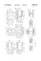
- FIG. 1A is a view in side elevation, partly broken away, of one illustrative embodiment of probe for the surgical instrument of the present invention, the inner tube being illustrated in a first or retracted position;
- FIG. 1B is a view corresponding to FIG. 1A, the inner tube being illustrated in a second or extended position;
- FIG. 1C is an end view thereof
- FIG. 2 is a view in side elevation, partly broken away, of a second illustrative embodiment of probe for the surgical instrument of the present invention
- FIG. 3 is a view in side elevation, partly broken away of a third illustrative embodiment of probe for the surgical instrument of the present invention.
- FIG. 4 is a view in side elevation, partly broken away of a fourth illustrative embodiment of probe for the surgical instrument of the present invention.
- FIG. 5 is a cross section view of an eyeball illustrating an embodiment of the probe for the surgical instrument of the present invention inserted therein, demonstrating a method for performing surgery with the instrument;
- FIG. 6 is a cross section view of an eyeball, illustrating the eye after such surgery
- FIG. 7 is a block diagrammatic view illustrating the surgical method employing the surgical instrument of the present invention.
- FIG. 8 is a top plan view of another embodiment of probe of the present invention.
- FIG. 9 is a side elevational view thereof.
- FIG. 10 is a cross section view of an eyeball illustrating probe of FIG. 8 inserted therein, demonstrating a method for performing surgery with the instrument;
- FIG. 11 is another cross section view of an eyeball illustrating probe of FIG. 8 and a small gauge cannula inserted therein, demonstrating another method of performing surgery with the instruments.
- Instrument 10 is a pneumatic vitrectomy probe constructed so as to have a generally elongated probe portion 12 and a handle section (not shown).
- Probe 12 includes an outer or first tube 14 and an inner or second tube 20.
- Tube 14 has an outer surface 14A, and interior surface 14B separated by a material thickness 14C therebetween and a closed distal tip 17.
- the surfaces 14A and 14B define an inner bore 15.
- Tube 14 is formed from surgical steel or other appropriate material.
- Tube 14 is sealed except for a aspiration port 16 formed through the material thickness 14C through the surfaces 14A and 14B.
- the inner tube 20 is sized so as to be generally concentric with and to be slideably engaged within bore 15 of outer tube 14. Inner tube 20 is slightly under-sized relative to bore 15 so that tube 14 can move or oscillate back and forth inside bore 15.
- instrument 10 also can be designed so that the tube 20 rotates about a central axis of and within bore 15.
- the tube 20 has a slightly flared distal end 22 and an elongated hollow tubular body section 23.
- the hollow body section defines a suction path 24.
- Distal end 22 of tube 20 defines an annular orifice 25.
- An edge 26 surrounding orifice 24 is constructed to act as a razor sharp cutting edge.
- Orifice 25 and suction path 24 are operatively connected to a conventional suction apparatus (not shown) which is controlled by the surgeon to exert appropriate suction through the instrument during use, as will be described below.
- the tube 20 is driven by an appropriate conventional power source, such as an electric motor or pneumatic power so that it oscillates, back-and-forth, within chamber 15 as previously described.
- FIG. 1A illustrate tube 20 in a retracted position
- FIG. 1B illustrate tube 20 in an extended position.
- the suction apparatus and power source can be contained in a conventional console and appropriately connected to instrument 10.
- Tube 20 oscillates while a suction is applied through path 24 and orifice 25.
- Semi-solid material such as intraocular vitreous, is pulled into aspirating port 16 and excised as cutting edge 26 moves past port 16 in a guillotine fashion. The severed material is sucked, through orifice 25 and path 24 into the suction apparatus for disposal.
- a gas delivery channel 28 is adjacent outer tube 14.
- channel 28 is an elongated tube extending along the length of outer tube 14.
- Channel 28 is positioned 90° to port 16.
- Channel 28 has an internal bore 30 terminating in an opening 31.
- Channel 28 is connected to a conventional source of non-expanding gas, such as air, which also can be provided through the aforementioned console.
- non-expanding gas means a gas which keeps eye pressure nearly normal, without requiring monitoring, during the procedure described below.
- Channel 28 is quite small in diameter, having the diameter of between approximately that of a 36 gauge needle (0.10 mm) and that of a 30 gauge needle (0.30 mm).
- Channel 28 allows the passage of non-expanding gas, such as air, through bore 30 but normally cannot accommodate the passage of a liquid, such as saline solution. It should be noted that the use of small gauge channel 28 to deliver only non-expanding gas allows the overall outer diameter of probe 12 to be quite small, being less than that of a 23 gauge needle (0.64 mm), and preferably less than that of a 25 gauge needle (0.51 mm).
- FIG. 2 illustrates another embodiment of a surgical instrument of the present invention indicated generally by reference numeral 40.
- Instrument 40 includes a generally elongated probe 42.
- Probe 42 is defined by a sealed first or outer tube 44 having an internal bore 45 formed in it.
- An aspirating port 46 is formed in a side 47 of tube 44.
- a second or inner tube 48 is slideably positioned within bore 45.
- Tube 44 and tube 48 are formed from surgical steel or other appropriate material.
- Tube 48 has an elongated, tubular body section 50 having an aspiration or vacuum channel 52 foraged in it.
- Body section 50 terminates at its distal end in a flared end 54.
- end 54 is a frusto-conical element formed to provide a razor sharp cutting edge 56.
- the edge 56 surrounds and defines an annular orifice 57.
- Body section 50 is slightly under-sized relative to bore 45 creating a gas flow channel 58 around body section 50.
- a gas port 60 is formed in a side 61 of tube 44, positioned approximately 90° relative to port 46, gas port 60 operatively communicates with gas flow channel 58.
- the channel 58 normally is large enough to allow only the passage of non-expanding gas, such as air.
- the channel 58 has a cross-sectional area between approximately the size of a 36 gauge needle (0.10 mm) and the size of a 30 gauge needle (0.30 m). Because of the extremely small size of channel 58, which allows only the passage of non-expanding gas, the overall outer diameter of probe 40 is quite small and preferably is approximately the diameter of a 23 gauge needle (0.64 mm) or less.
- Tube 48 is connected to a conventional drive console, as previously described, (i) to provide power, either electric or pneumatic, to drive tube 48 within tube 44; (ii) to provide appropriate controlled suction through vacuum channel 52 and orifice 57; and (iii) to provide a source of non-expanding gas to channel 58.
- FIG. 3 illustrates another embodiment of a surgical instrument of the present invention, indicated generally by reference numeral 70.
- Instrument 70 is defined in part by an elongated probe section 72.
- Probe 72 includes a first or outer tube 74 having an internal longitudinal bore 76 formed in it.
- Tube 74 again, is constructed from surgical stainless steel, for example.
- a bevel 78 is formed at the distal end of tube 74, such that the tube end defines an annular razor sharp, cutting edge 80.
- a concentric second or inner tube 82 is slideably engaged in bore 76.
- the tube 82 extends distally beyond bevel 78.
- Tube 82 has a distal end 84.
- a vacuum channel 86 is formed in and extends through tube 82.
- Channel 86 terminates in a suction orifice 88, formed through a side of tube 82.
- Vacuum channel 86 is operatively connected to a conventional vacuum source (not shown) controllable by the surgeon.
- Tube 82 is connected to a conventional power console (not shown) to provide oscillating power to tube 82.
- Tube 82 oscillates back-and-forth within tube 74.
- vitreous or other semi-solid intraocular tissue is drawn into port 88 by a controlled suction and severed by cutting edge 80 upon the oscillation of tube 82.
- a non-expanding gas delivery tube 90, with internal bore 92 and orifice 93, is provided adjacent external tube 74.
- Tube 90 is very small, normally allowing only the passage of non-expanding gas through bore 92.
- Tube 90 has an outer diameter approximately between the diameter of a 36 gauge needle (0.10 mm) and the diameter of a 30 gauge needle (0.30 mm). Therefore, the overall diameter of probe 72 can be and is quite small, approximately that of a 23 gauge needle (0.64 mm) or less.
- FIG. 4 illustrates yet another embodiment of the instrument of the present invention, indicated by reference numeral 100.
- Instrument 100 includes an elongated probe section 102 operatively associated with a conventional handle (not shown).
- Probe 102 includes a first elongated tube 104 defining a longitudinal bore 106.
- Tube 108 has an aspirating port 108 formed in a side 109 of it.
- a second or inner tube 110 is slideably engaged in bore 106.
- Tube 110 has a hollow, elongated body section 112 defining a vacuum channel 114.
- the body section 112 terminates at a flared section 116.
- Flared section 116 is formed to provide by a razor sharp cutting edge 120 surrounding an annular orifice 118.
- a third tube 122 surrounds, but is slightly spaced from, tube 104, to create an non-expanding gas channel 124 between the respective tubes 104, 122.
- a plurality of gas ports, such as 126 are formed in tube 122 as to communicate with channel 124.
- Channel 124 is very small, normally allowing only the passage of non-expanding gas through ports 126.
- the overall outer diameter of instrument 100 can be and is very small, approximately that of a 23 gauge needle or less.
- FIGS. 5-7 illustrate the use of an embodiment of surgical instrument of the present invention to perform a simple retinal reattachment.
- Instrument 10 is inserted inside eyeball E.
- the anatomical structures of the eyeball include sclera S, choroid C, iris I, lens LE, optic nerve N, vitreous cavity V, vitreous material M, central retinal artery A and retina R.
- FIG. 5 illustrates a tear T in retina R and the retina R is pulled away from choroid C. There also is sub-retinal fluid F behind retina R.
- the surgeon makes a small incision in the sclera S to form a sclerotomy of less than 1.0 mm.
- the sclerotomy is made at either the pars plan P1 or pars plicata P2, 2 to 5 mm behind the limbus.
- the surgical knife is withdrawn and the patient is positioned either in the supine, sitting, or prone position.
- the surgical instrument of the present invention shown generally as reference numeral 10, is inserted through the sclerotomy.
- the tip of instrument 10 is observed by the surgeon in the vitreous cavity V through an operating microscope (not shown), an indirect ophthalmoscope (not shown), or a slit lamp (not shown), for example.
- Non-expanding gas G is injected through gas channel 28 while, simultaneously, vitreous material M is aspirated, cut and suctioned away by the cutting and aspirating action of the concentric tubes of instrument 10, as previously described.
- Gas G migrates toward retina R and tear T exerting pressure against retina R, moving it toward choroid C.
- Subretinal fluid F is forced out through tear T allowing the movement of retina R toward choroid C, simultaneously positioning retina R against the choroid for attachment.
- instrument 10 After the injection of a sufficient amount of non-expanding gas, instrument 10 is gradually withdrawn until it exits from the sclerotomy site. Continuous aspiration and cutting may be employed during removal of the instrument. Retina R, which is now positioned for attachment, can be coagulated using cryocoagulation or laser photocoagulation through the pupil. Due to the very small size of instrument 10, the sclerotomy is small and may be self-sealing or, at most, may require a single suture to close.
- non-expanding gas G is eventually absorbed as the eyeball refills with naturally produced aqueous humor.
- FIGS. 8 and 9 illustrate another embodiment of a surgical instrument of the present invention indicated generally by reference numeral 200.
- Instrument 200 is a vitrectomy probe constructed so as to have a generally elongated probe portion 202 and a handle section (not shown).
- Probe 202 includes an outer or first tube 204 and an inner or second tube 206.
- Tube 204 has an outer surface 208 and an interior surface 210 separated by a material thickness 212 therebetween, and a distal extension tip 214.
- Distal extension tip 214 has a semicircular or curved bottom wall 216 and a downwardly sloping, yet slightly concave top wall 218. Walls 216 and 218 abut at edge 220. It will be appreciated that edge 220 is razor sharp so that probe 202 can pierce the eyeball without performing a separate sclerotomy.
- Tube 204 has an internal bore 222.
- Tube 204 is formed from surgical steel or other appropriate material.
- Tube 204 is sealed except for an aspiration port 224 formed though the material thickness 212 through the surfaces 208 and 210.
- Aspiration port 224 has a sharp peripheral edge 225. It will be appreciated that aspiration port 224 is separated from edge 220 by a relatively significant distance D. Distance D allows edge 220 to engage retinal tissue and move it away from port 224 as will be explained in greater detail below. It will be appreciated by those skilled in the art that the extension tip 214 could have a rounded or dull edge 220. In that case, the tip 214 is still used to urge retinal tissue away from the aspiration port, but could not be used to pierce the eyeball. A separate sclerotomy would be performed to allow introduction of the probe.
- Inner tube 206 is sized so as to be generally concentric with and to be slideably engaged within bore 222. Inner tube 206 is slightly undersized relative to bore 222 so that tube 206 can move or oscillate back and forth within bore 222.
- Tube 206 has an elongated hollow body section 226 with a flared distal end 230. The hollow body section defines a suction path 231. Distal end 230 of tube 206 defines an annular orifice 232. An edge 234 surrounding orifice 232 is constructed to act as a razor sharp cutting edge. Orifice 232 and suction path 231 are operatively connected to a conventional suction apparatus (not shown) which is controlled by the surgeon to exert appropriate suction through the instrument during use.
- the tube 206 is driven by an appropriate conventional power source, such as an electric motor or pneumatic power so that it oscillates, back-and-forth, within bore 222 as previously described.
- the inner tube 206 could be rotated within outer tube 204, without departing from the scope of the invention.
- probe 202 is quite small, ranging in size from that of a 20 gauge needle (0.9 mm) down to a 25 gauge needle (0.51 mm). The preferred size approximately is that of a 23 gauge needle (0.635 mm).
- FIG. 10 illustrates probe 202 in use.
- the surgeon can introduce probe 202 into the eye by placing edge 220 against the eye ball and exerting pressure.
- the anatomical structures of the eyeball E include sclera S, choroid C, iris I, lens LE, optic nerve N, vitreous cavity V, vitreous material M, central retinal artery A and retina R.
- FIG. 10 shows a tear T in retina R and the retina R is pulled away from choroid C.
- Tube 206 oscillates while suction is applied through path 231 and orifice 232.
- Semi-solid material such as vitreous material M, is pulled into aspirating port 224 and excised as cutting edge moves past port 224 in a guillotine fashion.
- edge 220 can engage detached retinal tissue R. Due to the filmy, pliant nature of the retinal tissue R, edge 220 does not sever the tissue. However, due to the presence of distance D between edge 220 and aspiration port 224, the tissue is moved away from the port by the extension tip 214 so that it is not sucked into the aspiration port 224 and damaged. The surgeon can use tip 214 to reposition the retina R against the choroid C. When probe 202 is removed, no suture is required.
- FIG. 11 illustrates another method of reattaching a retina.
- a probe such as probe 202
- a tear T in retina R.
- the depth of insertion may vary. I have found that the instrument need only be inserted to a depth of approximately 4 mm for certain procedures.
- a very small gauge needle or cannula 240 also is introduced into the eye. It will be appreciated that cannula 240 is quite small, ranging in size from a 20 gauge needle down to a 30 gauge needle. Cannula 240 needs only to be large enough to allow the passage of non-expanding gas therethrough. Therefore, cannula 240 preferably is a 30 gauge needle. The instruments are visualized by the surgeon as previously described.
- Non-expanding gas G is injected through needle 240 while, simultaneously, vitreous material M is aspirated and cut and suction away by probe 202.
- Gas G migrates toward retina R, moving it toward choroid C.
- Subretinal fluid F is forced out through tear T allowing the retina R to move toward the choroid C.
- needle 240 is withdrawn. The needle 240 is so small that no suture is required.
- Probe 202 also is gradually withdrawn. Continuous cutting and aspiration may take place during the withdrawal of the probe.
- the retina R which is now in contact with the choroid C can be attached thereto using cryo-therapy or any other conventional attachment technique.
- any appropriate small gauge vitrectomy probe may be used along with a small gauge non-expanding gas delivery cannula to effect the method.
- a small gauge vitrectomy probe having a blunt or rounded tip may be used. In that instance, the surgeon would first make a small sclerotomy incision to accommodate insertion of the probe.
- the probe employed with the instrument described may have first and second diameter L portions.
- the overall length of the probe 42 is divided into a first diameter part L1 and a second diameter part L2 by a shoulder 59, the diameter part L2 being substantially larger than the diameter part L1.
- ophthalmological probes up to 40 mm in length are known, a probe having a length of 12 mm to 14 mm would be sufficient for most retinal procedures.
- the part L1 in operational use need only have a length of about 4 mm to about 14 mm to function well in the procedures described above. Any additional probe length and handling part for the instrument may correspond to the larger diameter part L2, or similar equivalent structure. While the increased diameter part L2 is illustratively shown in conjunction with and respect to the probe 42 of instrument 40, those skilled in the art will recognize that similar variable diameter configurations may be used with all of the embodiments described.
Abstract
Description
Claims (18)
Priority Applications (4)
| Application Number | Priority Date | Filing Date | Title |
|---|---|---|---|
| US08/348,051 US5487725A (en) | 1994-05-12 | 1994-12-01 | Pneumatic vitrectomy for retinal attachment |
| EP95918848A EP0760627A4 (en) | 1994-05-12 | 1995-05-04 | Pneumatic vitrectomy for retinal attachment |
| PCT/US1995/005091 WO1995031141A1 (en) | 1994-05-12 | 1995-05-04 | Pneumatic vitrectomy for retinal attachment |
| AU24612/95A AU2461295A (en) | 1994-05-12 | 1995-05-04 | Pneumatic vitrectomy for retinal attachment |
Applications Claiming Priority (2)
| Application Number | Priority Date | Filing Date | Title |
|---|---|---|---|
| US08/241,749 US5547473A (en) | 1994-05-12 | 1994-05-12 | Pneumatic vitrectomy for retinal attachment |
| US08/348,051 US5487725A (en) | 1994-05-12 | 1994-12-01 | Pneumatic vitrectomy for retinal attachment |
Related Parent Applications (1)
| Application Number | Title | Priority Date | Filing Date |
|---|---|---|---|
| US08/241,749 Continuation-In-Part US5547473A (en) | 1994-05-12 | 1994-05-12 | Pneumatic vitrectomy for retinal attachment |
Publications (1)
| Publication Number | Publication Date |
|---|---|
| US5487725A true US5487725A (en) | 1996-01-30 |
Family
ID=26934540
Family Applications (1)
| Application Number | Title | Priority Date | Filing Date |
|---|---|---|---|
| US08/348,051 Expired - Lifetime US5487725A (en) | 1994-05-12 | 1994-12-01 | Pneumatic vitrectomy for retinal attachment |
Country Status (4)
| Country | Link |
|---|---|
| US (1) | US5487725A (en) |
| EP (1) | EP0760627A4 (en) |
| AU (1) | AU2461295A (en) |
| WO (1) | WO1995031141A1 (en) |
Cited By (104)
| Publication number | Priority date | Publication date | Assignee | Title |
|---|---|---|---|---|
| US5733297A (en) * | 1996-09-10 | 1998-03-31 | Medical Instrument Development Laboratories, Inc. | Cutter for surgical probe |
| DE19714475C1 (en) * | 1997-04-08 | 1998-12-17 | Wavelight Laser Technologie Gm | Unit for the removal of glass components from the eye |
| WO1999065432A1 (en) * | 1998-06-17 | 1999-12-23 | Raymond Sjaarda | Surgical infusion tool with flow diffuser |
| US6045535A (en) * | 1996-06-13 | 2000-04-04 | One Way Ocular Technology Ltd. | Surgical sealing sleeve |
| US6290690B1 (en) * | 1999-06-21 | 2001-09-18 | Alcon Manufacturing, Ltd. | Simultaneous injection and aspiration of viscous fluids in a surgical system |
| EP1139527A2 (en) * | 2000-03-27 | 2001-10-04 | Matsushita Electric Industrial Co., Ltd. | High power semiconductor laser array apparatus |
| EP1143584A2 (en) * | 2000-03-31 | 2001-10-10 | Matsushita Electric Industrial Co., Ltd. | Semiconductor laser array |
| EP1146617A2 (en) * | 2000-03-31 | 2001-10-17 | Matsushita Electric Industrial Co., Ltd. | High-powered semiconductor laser array apparatus |
| WO2001068016A3 (en) * | 2000-03-11 | 2002-07-25 | Univ Johns Hopkins | Sutureless ocular surgical methods and instruments |
| US20020198511A1 (en) * | 2001-06-22 | 2002-12-26 | Varner Signe Erickson | Method and device for subretinal drug delivery |
| US6527736B1 (en) * | 2000-10-23 | 2003-03-04 | Grieshaber & Co. Ag Schaffhausen | Device for use in ophthalmologic procedures |
| US6551291B1 (en) * | 1999-08-04 | 2003-04-22 | Johns Hopkins University | Non-traumatic infusion cannula and treatment methods using same |
| US20030078589A1 (en) * | 1998-04-01 | 2003-04-24 | Preissman Howard E. | High pressure applicator |
| US20040073139A1 (en) * | 2002-10-11 | 2004-04-15 | Hirsch Joshua A. | Cannula for extracting and implanting material |
| US6730106B2 (en) * | 2000-10-20 | 2004-05-04 | Nidek Co., Ltd. | Vitreous surgical apparatus |
| US20040133218A1 (en) * | 2003-01-07 | 2004-07-08 | Charles Steven T. | Wound clamp |
| US6852093B1 (en) * | 2004-05-10 | 2005-02-08 | Alcon, Inc. | Surgical method and apparatus |
| US20050033309A1 (en) * | 2003-01-29 | 2005-02-10 | Edwin Ryan | Small gauge surgical instrument with support device |
| US20050143363A1 (en) * | 2002-09-29 | 2005-06-30 | Innorx, Inc. | Method for subretinal administration of therapeutics including steroids; method for localizing pharmacodynamic action at the choroid of the retina; and related methods for treatment and/or prevention of retinal diseases |
| US20050177019A1 (en) * | 2001-02-22 | 2005-08-11 | Dejuan Eugene Jr. | Ophthalmic treatment apparatus |
| WO2005086772A2 (en) * | 2004-03-05 | 2005-09-22 | Auld Michael D | Rigid shafted instrumentation for vitreoretinal surgery |
| US20050251204A1 (en) * | 2004-05-06 | 2005-11-10 | Jurg Attinger | Wound clamp |
| US20050277802A1 (en) * | 2004-02-12 | 2005-12-15 | Larsen Charles E | Method and apparatus for intraocular brachytherapy |
| US20060064101A1 (en) * | 2004-02-12 | 2006-03-23 | Arthrocare Corporation | Bone access system |
| US20060111605A1 (en) * | 2004-02-12 | 2006-05-25 | Larsen Charles E | Methods and apparatus for intraocular brachytherapy |
| US20060110428A1 (en) * | 2004-07-02 | 2006-05-25 | Eugene Dejuan | Methods and devices for the treatment of ocular conditions |
| US20060142779A1 (en) * | 2004-12-23 | 2006-06-29 | Arthrocare Corporation | Cannula having asymmetrically-shaped threads |
| US20060164913A1 (en) * | 2005-01-21 | 2006-07-27 | Arthrocare Corporation | Multi-chamber integrated mixing and delivery system |
| US20060212004A1 (en) * | 2005-03-15 | 2006-09-21 | Atil Plaridel C | Medical needle having a closed tip |
| US20060257451A1 (en) * | 2005-04-08 | 2006-11-16 | Varner Signe E | Sustained release implants and methods for subretinal delivery of bioactive agents to treat or prevent retinal disease |
| US20060259008A1 (en) * | 2005-04-27 | 2006-11-16 | Allergan, Inc. | Apparatus and methods useful for intravitreal injection of drugs |
| US20070038174A1 (en) * | 2005-08-09 | 2007-02-15 | Hopkins Mark A | Ophthalmic injector system |
| US20070060887A1 (en) * | 2005-08-22 | 2007-03-15 | Marsh David A | Ophthalmic injector |
| US20070093793A1 (en) * | 2005-10-11 | 2007-04-26 | Maurer Robert S Jr | Microsurgical probe |
| US20070106300A1 (en) * | 2005-11-08 | 2007-05-10 | Alcon, Inc. | Surgical probe |
| US20070118010A1 (en) * | 2005-02-11 | 2007-05-24 | Hillstead Richard A | Methods and apparatus for intraocular brachytherapy |
| US20070123812A1 (en) * | 2004-12-03 | 2007-05-31 | Leonard Pinchuk | Glaucoma Implant Device |
| US20070270777A1 (en) * | 2006-05-17 | 2007-11-22 | Bruno Dacquay | Ophthalmic Injection Device Using Shape Memory Alloy |
| US20070270768A1 (en) * | 2006-05-17 | 2007-11-22 | Bruno Dacquay | Mechanical Linkage Mechanism For Ophthalmic Injection Device |
| US20070268340A1 (en) * | 2006-05-17 | 2007-11-22 | Bruno Dacquay | Ophthalmic Injection System and Method Using Piezoelectric Array |
| US20070270750A1 (en) * | 2006-05-17 | 2007-11-22 | Alcon, Inc. | Drug delivery device |
| US20070270748A1 (en) * | 2006-05-17 | 2007-11-22 | Bruno Dacquay | Ophthalmic Injection Device Using Piezoelectric Array |
| US20070270744A1 (en) * | 2006-05-17 | 2007-11-22 | Bruno Dacquay | Limited Reuse Assembly For Ophthalmic Injection Device |
| US20080097390A1 (en) * | 2006-09-27 | 2008-04-24 | Alcon Manufacturing, Ltd. | Spring actuated delivery system |
| US20080097379A1 (en) * | 2006-09-26 | 2008-04-24 | Alcon Manufacturing, Ltd. | Ophthalmic injection method |
| US20080125712A1 (en) * | 2006-09-26 | 2008-05-29 | Alcon Manufacturing, Ltd. | Ophthalmic injection system |
| US20080154304A1 (en) * | 2006-12-21 | 2008-06-26 | Arthrocare Corporation | System and method for accessing a tissue structure |
| US20080195135A1 (en) * | 2007-02-12 | 2008-08-14 | Alcon, Inc. | Surgical Probe |
| US20080195044A1 (en) * | 2005-03-23 | 2008-08-14 | Akira Nishimura | Ophthalmic Cannula |
| US20090018548A1 (en) * | 2007-07-13 | 2009-01-15 | Charles Steven T | Pneumatically-Powered Intraocular Lens Injection Device with Removable Cartridge |
| US20090018512A1 (en) * | 2007-07-13 | 2009-01-15 | Charles Steven T | Pneumatically-Powered Ophthalmic Injector |
| US20090036846A1 (en) * | 2006-05-17 | 2009-02-05 | Bruno Dacquay | Ophthalmic Injection System |
| US20090036842A1 (en) * | 2007-08-03 | 2009-02-05 | Raffi Pinedjian | Consumable Activation Lever For Injection Device |
| US20090036868A1 (en) * | 2007-08-01 | 2009-02-05 | Raffi Pinedjian | Spring Driven Ophthalmic Injection Device with Safety Actuator Lockout Feature |
| US20090033279A1 (en) * | 2007-08-03 | 2009-02-05 | Raffi Pinedjian | Easy Cleaning C-Shaped Charging Base |
| US20090043321A1 (en) * | 2004-04-29 | 2009-02-12 | Iscience Interventional Corporation | Apparatus And Method For Surgical Enhancement Of Aqueous Humor Drainage |
| US20090287150A1 (en) * | 2006-10-16 | 2009-11-19 | Bruno Dacquay | Universal Rechargeable Limited Reuse Assembly For Ophthalmic Hand Piece |
| US20090287143A1 (en) * | 2008-05-15 | 2009-11-19 | Casey Line | Small Gauge Mechanical Tissue Cutter/Aspirator Probe For Glaucoma Surgery |
| US20090287233A1 (en) * | 2008-05-15 | 2009-11-19 | Huculak John C | Small Gauge Mechanical Tissue Cutter/Aspirator Probe For Glaucoma Surgery |
| US20100023065A1 (en) * | 2008-07-25 | 2010-01-28 | Welch Andrea M | Tissue access device with alignment guide and methods of use |
| US20100030136A1 (en) * | 2006-10-16 | 2010-02-04 | Bruno Dacquay | Ophthalmic Injection Device Including Dosage Control Device |
| US20100106083A1 (en) * | 2006-10-16 | 2010-04-29 | Alcon Research, Ltd. | Method of Operating Ophthalmic Hand Piece with Disposable End |
| US20100106089A1 (en) * | 2006-10-16 | 2010-04-29 | Cesario Dos Santos | Temperature control device and thermal sensor assembly for medical device |
| US20100152646A1 (en) * | 2008-02-29 | 2010-06-17 | Reshma Girijavallabhan | Intravitreal injection device and method |
| US20100173866A1 (en) * | 2004-04-29 | 2010-07-08 | Iscience Interventional Corporation | Apparatus and method for ocular treatment |
| US20100191177A1 (en) * | 2009-01-23 | 2010-07-29 | Iscience Interventional Corporation | Device for aspirating fluids |
| US20100191103A1 (en) * | 2002-09-17 | 2010-07-29 | Iscience Interventional Corporation | Apparatus and method for surgical bypass of aqueous humor |
| US20100211044A1 (en) * | 2006-05-17 | 2010-08-19 | Alcon Manufacturing, Lted. | Battery operated surgical hand piece with disposable end |
| US20100280408A1 (en) * | 2009-04-30 | 2010-11-04 | Rusnak Joseph G | Fine needle biopsy system and method of use |
| US20100286632A1 (en) * | 2009-05-06 | 2010-11-11 | Cesario Pereira Dos Santos | Multi-Layer Heat Assembly For A Drug Delivery Device |
| US20100312252A1 (en) * | 2009-06-03 | 2010-12-09 | Guangyao Jia | Capsularhexis device with flexible heating element having an angled transitional neck |
| US20100312232A1 (en) * | 2009-06-03 | 2010-12-09 | Guangyao Jia | Capsulotomy Repair Device and Method for Capsulotomy Repair |
| US20110152775A1 (en) * | 2009-12-23 | 2011-06-23 | Jose Luis Lopez | Ophthalmic valved trocar vent |
| US20110152767A1 (en) * | 2009-12-22 | 2011-06-23 | Pinedjian Raffi S | Method and Apparatus for Drug Delivery |
| US20110152774A1 (en) * | 2009-12-23 | 2011-06-23 | Jose Luis Lopez | Ophthalmic valved trocar cannula |
| US20110202049A1 (en) * | 2010-02-18 | 2011-08-18 | Alcon Research, Ltd. | Small Gauge Ablation Probe For Glaucoma Surgery |
| US8123756B2 (en) | 1999-09-30 | 2012-02-28 | Neurotherm, Inc. | High pressure delivery system |
| US8137344B2 (en) | 2008-12-10 | 2012-03-20 | Alcon Research, Ltd. | Flexible, automated capsulorhexis device |
| US8157797B2 (en) | 2009-01-12 | 2012-04-17 | Alcon Research, Ltd. | Capsularhexis device with retractable bipolar electrodes |
| US8353812B2 (en) | 2008-06-04 | 2013-01-15 | Neovista, Inc. | Handheld radiation delivery system |
| US8425473B2 (en) | 2009-01-23 | 2013-04-23 | Iscience Interventional Corporation | Subretinal access device |
| US20130150875A1 (en) * | 2011-12-08 | 2013-06-13 | Brian W. McDonell | Optimized Pneumatic Drive Lines |
| NL2008451C2 (en) * | 2012-03-09 | 2013-09-10 | D O R C Dutch Ophthalmic Res Ct International B V | EYE-SURGICAL INSTRUMENT. |
| WO2014034506A1 (en) * | 2012-08-28 | 2014-03-06 | マニー株式会社 | Vitreous body surgical probe, and method of manufacturing same |
| USD707818S1 (en) | 2013-03-05 | 2014-06-24 | Alcon Research Ltd. | Capsulorhexis handpiece |
| US20150005753A1 (en) * | 2012-03-05 | 2015-01-01 | Wake Forest University Health Sciences | Medical tools with aspiration tips suitable for cataract surgeries and related methods |
| USD737438S1 (en) | 2014-03-04 | 2015-08-25 | Novartis Ag | Capsulorhexis handpiece |
| US9125720B2 (en) | 2008-10-13 | 2015-09-08 | Alcon Research, Ltd. | Capsularhexis device with flexible heating element |
| US9149388B2 (en) | 2010-09-29 | 2015-10-06 | Alcon Research, Ltd. | Attenuated RF power for automated capsulorhexis |
| US9241755B2 (en) | 2010-05-11 | 2016-01-26 | Alcon Research, Ltd. | Capsule polishing device and method for capsule polishing |
| US9301736B2 (en) | 2009-04-30 | 2016-04-05 | Joseph G. Rusnak | Fine needle biopsy with adaptor |
| US20170042731A1 (en) * | 2014-04-23 | 2017-02-16 | Makoto Kishimoto | Intraocular surgery system |
| US9629748B2 (en) | 2012-05-31 | 2017-04-25 | Medical Instrument Development Laboratories, Inc. | Multi-stage tubing for high-speed pneumatic surgical cutter |
| US9693895B2 (en) | 2012-06-12 | 2017-07-04 | Altaviz, Llc | Intraocular gas injector |
| US9757536B2 (en) | 2012-07-17 | 2017-09-12 | Novartis Ag | Soft tip cannula |
| US9931244B2 (en) | 2003-01-29 | 2018-04-03 | Edwin Ryan | Small gauge surgical instrument with support device |
| WO2018189740A1 (en) * | 2017-04-09 | 2018-10-18 | Sanoculis Ltd. | Device and method for creating a channel in soft tissue |
| US10182939B2 (en) | 2015-09-16 | 2019-01-22 | Novartis Ag | Hydraulic injector and methods for intra-ocular lens insertion |
| US10543122B2 (en) | 2016-12-19 | 2020-01-28 | New World Medical, Inc. | Ocular treatment devices and related methods of use |
| US20200108198A1 (en) * | 2015-12-16 | 2020-04-09 | Novartis Ag | Surgical system with substance delivery system |
| US11020270B1 (en) | 2018-06-18 | 2021-06-01 | Gholam A. Peyman | Vitrectomy instrument and a system including the same |
| US11224537B2 (en) | 2018-10-19 | 2022-01-18 | Alcon Inc. | Intraocular gas injector |
| US11241333B2 (en) | 2014-03-20 | 2022-02-08 | Medical Instrument Development Laboratories, Inc. | Aspirating cutter and method to use |
| US11730890B1 (en) | 2020-01-07 | 2023-08-22 | Gholam A. Peyman | Plungerless aspiration and/or injection device and method using the same |
Families Citing this family (10)
| Publication number | Priority date | Publication date | Assignee | Title |
|---|---|---|---|---|
| US8679241B2 (en) | 2006-10-30 | 2014-03-25 | Novartis Ag | Gas pressure monitor for pneumatic surgical machine |
| US8162000B2 (en) | 2006-12-13 | 2012-04-24 | Novartis Ag | Adjustable pneumatic system for a surgical machine |
| US9241830B2 (en) | 2006-12-15 | 2016-01-26 | Novartis Ag | Pressure monitor for pneumatic vitrectomy machine |
| US8312800B2 (en) * | 2006-12-21 | 2012-11-20 | Novartis Ag | Pneumatic system for a vitrector |
| US8080029B2 (en) | 2007-09-21 | 2011-12-20 | Novartis Ag | System for actuation of a vitreous cutter |
| JP5770731B2 (en) | 2009-08-31 | 2015-08-26 | アルコン リサーチ, リミテッド | Control of pneumatic output by drive valve duty |
| AU2010328590B2 (en) | 2009-12-10 | 2015-09-17 | Alcon Inc. | Systems and methods for dynamic pneumatic valve driver |
| US8821524B2 (en) | 2010-05-27 | 2014-09-02 | Alcon Research, Ltd. | Feedback control of on/off pneumatic actuators |
| US8808318B2 (en) | 2011-02-28 | 2014-08-19 | Alcon Research, Ltd. | Surgical probe with increased fluid flow |
| US9060841B2 (en) | 2011-08-31 | 2015-06-23 | Alcon Research, Ltd. | Enhanced flow vitrectomy probe |
Citations (19)
| Publication number | Priority date | Publication date | Assignee | Title |
|---|---|---|---|---|
| US3776238A (en) * | 1971-08-24 | 1973-12-04 | Univ California | Ophthalmic instrument |
| US3815604A (en) * | 1972-06-19 | 1974-06-11 | Malley C O | Apparatus for intraocular surgery |
| US3884238A (en) * | 1972-06-19 | 1975-05-20 | Malley Conor C O | Apparatus for intraocular surgery |
| US3995619A (en) * | 1975-10-14 | 1976-12-07 | Glatzer Stephen G | Combination subcutaneous suture remover, biopsy sampler and syringe |
| US4011869A (en) * | 1975-08-01 | 1977-03-15 | David Kopf Instruments | Tubular cutting instrument |
| US4210146A (en) * | 1978-06-01 | 1980-07-01 | Anton Banko | Surgical instrument with flexible blade |
| US4246902A (en) * | 1978-03-10 | 1981-01-27 | Miguel Martinez | Surgical cutting instrument |
| US4530356A (en) * | 1983-02-08 | 1985-07-23 | Helfgott Maxwell A | Ophthalmic surgical instrument with beveled tip |
| US4577629A (en) * | 1983-10-28 | 1986-03-25 | Coopervision, Inc. | Surgical cutting instrument for ophthalmic surgery |
| US4652255A (en) * | 1983-10-28 | 1987-03-24 | Miguel Martinez | Irrigating and aspirating handpiece for use in ophthalmic surgery |
| US5019035A (en) * | 1989-06-07 | 1991-05-28 | Alcon Surgical, Inc. | Cutting assembly for surgical cutting instrument |
| US5037384A (en) * | 1988-01-12 | 1991-08-06 | Cornell Research Foundation, Inc. | Method and apparatus for the treatment of complicated retinal detachments |
| US5047008A (en) * | 1989-10-27 | 1991-09-10 | Storz Instrument Company | Vitrectomy probe |
| US5059204A (en) * | 1989-10-26 | 1991-10-22 | Site Microsurgical Systems, Inc. | Ocular cutter with enhanced cutting action |
| US5106364A (en) * | 1989-07-07 | 1992-04-21 | Kabushiki Kaisha Topcon | Surgical cutter |
| US5226910A (en) * | 1989-07-05 | 1993-07-13 | Kabushiki Kaisha Topcon | Surgical cutter |
| US5284472A (en) * | 1992-10-30 | 1994-02-08 | Allergan, Inc. | Vitreous cutter |
| US5328481A (en) * | 1988-06-21 | 1994-07-12 | Alcon Laboratories, Inc. | Method for injecting viscous fluid into the eye to lift retinal membrane |
| US5336175A (en) * | 1992-10-29 | 1994-08-09 | Mames Robert N | Method for the treatment of retinal detachments |
Family Cites Families (2)
| Publication number | Priority date | Publication date | Assignee | Title |
|---|---|---|---|---|
| US4167943A (en) * | 1977-06-27 | 1979-09-18 | Surgical Design Corp. | Blade type rotatable surgical cutting instrument with improved cutter blade wear |
| GB2018601A (en) * | 1978-03-28 | 1979-10-24 | Microsurgical Administrative S | Surgical cutting apparatus |
-
1994
- 1994-12-01 US US08/348,051 patent/US5487725A/en not_active Expired - Lifetime
-
1995
- 1995-05-04 WO PCT/US1995/005091 patent/WO1995031141A1/en not_active Application Discontinuation
- 1995-05-04 AU AU24612/95A patent/AU2461295A/en not_active Abandoned
- 1995-05-04 EP EP95918848A patent/EP0760627A4/en not_active Withdrawn
Patent Citations (21)
| Publication number | Priority date | Publication date | Assignee | Title |
|---|---|---|---|---|
| US3776238A (en) * | 1971-08-24 | 1973-12-04 | Univ California | Ophthalmic instrument |
| US3815604A (en) * | 1972-06-19 | 1974-06-11 | Malley C O | Apparatus for intraocular surgery |
| US3884238A (en) * | 1972-06-19 | 1975-05-20 | Malley Conor C O | Apparatus for intraocular surgery |
| US4011869A (en) * | 1975-08-01 | 1977-03-15 | David Kopf Instruments | Tubular cutting instrument |
| US3995619A (en) * | 1975-10-14 | 1976-12-07 | Glatzer Stephen G | Combination subcutaneous suture remover, biopsy sampler and syringe |
| US4246902A (en) * | 1978-03-10 | 1981-01-27 | Miguel Martinez | Surgical cutting instrument |
| US4210146A (en) * | 1978-06-01 | 1980-07-01 | Anton Banko | Surgical instrument with flexible blade |
| US4530356A (en) * | 1983-02-08 | 1985-07-23 | Helfgott Maxwell A | Ophthalmic surgical instrument with beveled tip |
| US4577629A (en) * | 1983-10-28 | 1986-03-25 | Coopervision, Inc. | Surgical cutting instrument for ophthalmic surgery |
| US4652255A (en) * | 1983-10-28 | 1987-03-24 | Miguel Martinez | Irrigating and aspirating handpiece for use in ophthalmic surgery |
| US5037384A (en) * | 1988-01-12 | 1991-08-06 | Cornell Research Foundation, Inc. | Method and apparatus for the treatment of complicated retinal detachments |
| US5037384B2 (en) * | 1988-01-12 | 1995-12-26 | Cornell Res Foundation Inc | Method and apparatus for the treatment of complicated retinal detachments |
| US5037384B1 (en) * | 1988-01-12 | 1994-08-16 | Cornell Res Foundation Inc | Method and apparatus for the treatment of complicated retinal detachments |
| US5328481A (en) * | 1988-06-21 | 1994-07-12 | Alcon Laboratories, Inc. | Method for injecting viscous fluid into the eye to lift retinal membrane |
| US5019035A (en) * | 1989-06-07 | 1991-05-28 | Alcon Surgical, Inc. | Cutting assembly for surgical cutting instrument |
| US5226910A (en) * | 1989-07-05 | 1993-07-13 | Kabushiki Kaisha Topcon | Surgical cutter |
| US5106364A (en) * | 1989-07-07 | 1992-04-21 | Kabushiki Kaisha Topcon | Surgical cutter |
| US5059204A (en) * | 1989-10-26 | 1991-10-22 | Site Microsurgical Systems, Inc. | Ocular cutter with enhanced cutting action |
| US5047008A (en) * | 1989-10-27 | 1991-09-10 | Storz Instrument Company | Vitrectomy probe |
| US5336175A (en) * | 1992-10-29 | 1994-08-09 | Mames Robert N | Method for the treatment of retinal detachments |
| US5284472A (en) * | 1992-10-30 | 1994-02-08 | Allergan, Inc. | Vitreous cutter |
Cited By (191)
| Publication number | Priority date | Publication date | Assignee | Title |
|---|---|---|---|---|
| US6045535A (en) * | 1996-06-13 | 2000-04-04 | One Way Ocular Technology Ltd. | Surgical sealing sleeve |
| US5733297A (en) * | 1996-09-10 | 1998-03-31 | Medical Instrument Development Laboratories, Inc. | Cutter for surgical probe |
| DE19714475C1 (en) * | 1997-04-08 | 1998-12-17 | Wavelight Laser Technologie Gm | Unit for the removal of glass components from the eye |
| US6027493A (en) * | 1997-04-08 | 2000-02-22 | Wavelight Laser Technologie Gmbh | Device and method for the removal of body substances |
| US20030078589A1 (en) * | 1998-04-01 | 2003-04-24 | Preissman Howard E. | High pressure applicator |
| US6695821B1 (en) | 1998-06-17 | 2004-02-24 | Raymond N. Sjaarda | Surgical infusion tool with flow diffuser |
| WO1999065432A1 (en) * | 1998-06-17 | 1999-12-23 | Raymond Sjaarda | Surgical infusion tool with flow diffuser |
| US6290690B1 (en) * | 1999-06-21 | 2001-09-18 | Alcon Manufacturing, Ltd. | Simultaneous injection and aspiration of viscous fluids in a surgical system |
| US6551291B1 (en) * | 1999-08-04 | 2003-04-22 | Johns Hopkins University | Non-traumatic infusion cannula and treatment methods using same |
| US8123756B2 (en) | 1999-09-30 | 2012-02-28 | Neurotherm, Inc. | High pressure delivery system |
| WO2001068016A3 (en) * | 2000-03-11 | 2002-07-25 | Univ Johns Hopkins | Sutureless ocular surgical methods and instruments |
| US7077848B1 (en) | 2000-03-11 | 2006-07-18 | John Hopkins University | Sutureless occular surgical methods and instruments for use in such methods |
| US20040073231A1 (en) * | 2000-03-11 | 2004-04-15 | Juan Eugene De | Sutureless occular surgical methods and instruments for use in such methods |
| US20010033590A1 (en) * | 2000-03-27 | 2001-10-25 | Masaaki Yuri | High-power semiconductor laser array apparatus that outputs laser lights matched in wavelength and phase, manufacturing method therefor, and multi-wavelength laser emitting apparatus using such high-power semiconductor laser array apparatus |
| EP1139527A3 (en) * | 2000-03-27 | 2003-04-23 | Matsushita Electric Industrial Co., Ltd. | High power semiconductor laser array apparatus |
| EP1139527A2 (en) * | 2000-03-27 | 2001-10-04 | Matsushita Electric Industrial Co., Ltd. | High power semiconductor laser array apparatus |
| US6826224B2 (en) | 2000-03-27 | 2004-11-30 | Matsushita Electric Industrial Co., Ltd. | High-power semiconductor laser array apparatus that outputs laser lights matched in wavelength and phase, manufacturing method therefor, and multi-wavelength laser emitting apparatus using such high-power semiconductor laser array apparatus |
| US6904068B2 (en) | 2000-03-31 | 2005-06-07 | Matsushita Electric Inustrial Co., Ltd. | Semiconductor laser device and multiple wavelength laser light emitting apparatus employing the semiconductor laser device |
| EP1143584A3 (en) * | 2000-03-31 | 2003-04-23 | Matsushita Electric Industrial Co., Ltd. | Semiconductor laser array |
| EP1146617A2 (en) * | 2000-03-31 | 2001-10-17 | Matsushita Electric Industrial Co., Ltd. | High-powered semiconductor laser array apparatus |
| EP1143584A2 (en) * | 2000-03-31 | 2001-10-10 | Matsushita Electric Industrial Co., Ltd. | Semiconductor laser array |
| EP1146617A3 (en) * | 2000-03-31 | 2003-04-23 | Matsushita Electric Industrial Co., Ltd. | High-powered semiconductor laser array apparatus |
| US6730106B2 (en) * | 2000-10-20 | 2004-05-04 | Nidek Co., Ltd. | Vitreous surgical apparatus |
| US6527736B1 (en) * | 2000-10-23 | 2003-03-04 | Grieshaber & Co. Ag Schaffhausen | Device for use in ophthalmologic procedures |
| US8100818B2 (en) | 2001-02-22 | 2012-01-24 | TDH Partners, Inc. | Beta radiotherapy emitting surgical device and methods of use thereof |
| US20050177019A1 (en) * | 2001-02-22 | 2005-08-11 | Dejuan Eugene Jr. | Ophthalmic treatment apparatus |
| US20070265485A1 (en) * | 2001-02-22 | 2007-11-15 | Dejuan Eugene Jr | Beta radiotherapy emitting surgical device and methods of use thereof |
| US7276019B2 (en) | 2001-02-22 | 2007-10-02 | Retinalabs, Inc. | Ophthalmic treatment apparatus |
| US7223225B2 (en) | 2001-02-22 | 2007-05-29 | Retinalabs, Inc. | Intraocular radiotherapy treatment for macular degeneration |
| US7220225B2 (en) * | 2001-02-22 | 2007-05-22 | Retinalabs, Inc. | Intraocular radiotherapy treatment |
| US20060142629A1 (en) * | 2001-02-22 | 2006-06-29 | Dejuan Eugene Jr | Intraocular radiotherapy treatment for macular degeneration |
| US20060189838A1 (en) * | 2001-02-22 | 2006-08-24 | Dejuan Eugene Jr | Intraocular radiotherapy treatment |
| US20080154204A1 (en) * | 2001-06-22 | 2008-06-26 | The Johns Hopkins University | Method and device for subretinal drug delivery |
| US7485113B2 (en) | 2001-06-22 | 2009-02-03 | Johns Hopkins University | Method for drug delivery through the vitreous humor |
| US20020198511A1 (en) * | 2001-06-22 | 2002-12-26 | Varner Signe Erickson | Method and device for subretinal drug delivery |
| US20100191103A1 (en) * | 2002-09-17 | 2010-07-29 | Iscience Interventional Corporation | Apparatus and method for surgical bypass of aqueous humor |
| US20050143363A1 (en) * | 2002-09-29 | 2005-06-30 | Innorx, Inc. | Method for subretinal administration of therapeutics including steroids; method for localizing pharmacodynamic action at the choroid of the retina; and related methods for treatment and/or prevention of retinal diseases |
| US20040073139A1 (en) * | 2002-10-11 | 2004-04-15 | Hirsch Joshua A. | Cannula for extracting and implanting material |
| US20040133218A1 (en) * | 2003-01-07 | 2004-07-08 | Charles Steven T. | Wound clamp |
| US11744733B2 (en) | 2003-01-29 | 2023-09-05 | Edwin Ryan | Small gauge surgical instrument with support device |
| US20050033309A1 (en) * | 2003-01-29 | 2005-02-10 | Edwin Ryan | Small gauge surgical instrument with support device |
| US8202277B2 (en) * | 2003-01-29 | 2012-06-19 | Edwin Ryan | Small gauge surgical instrument with support device |
| US8308737B2 (en) | 2003-01-29 | 2012-11-13 | Edwin Ryan | Small gauge surgical instrument with support device |
| US9931244B2 (en) | 2003-01-29 | 2018-04-03 | Edwin Ryan | Small gauge surgical instrument with support device |
| US10898373B2 (en) | 2003-01-29 | 2021-01-26 | Dr. Edwin Ryan | Small gauge surgical instrument with support device |
| US7803102B2 (en) | 2004-02-12 | 2010-09-28 | Neovista, Inc. | Methods and apparatus for intraocular brachytherapy |
| US20060064101A1 (en) * | 2004-02-12 | 2006-03-23 | Arthrocare Corporation | Bone access system |
| US8365721B2 (en) | 2004-02-12 | 2013-02-05 | Neovista Inc. | Methods and apparatus for intraocular brachytherapy |
| US7951060B2 (en) | 2004-02-12 | 2011-05-31 | Neovista, Inc. | Methods and apparatus for intraocular brachytherapy |
| US20060111605A1 (en) * | 2004-02-12 | 2006-05-25 | Larsen Charles E | Methods and apparatus for intraocular brachytherapy |
| US20110004045A1 (en) * | 2004-02-12 | 2011-01-06 | Larsen Charles E | Methods And Apparatus for Intraocular Brachytherapy |
| US7563222B2 (en) | 2004-02-12 | 2009-07-21 | Neovista, Inc. | Methods and apparatus for intraocular brachytherapy |
| US20100268013A1 (en) * | 2004-02-12 | 2010-10-21 | Larsen Charles E | Methods and apparatus for intraocular brachytherapy |
| US20050277802A1 (en) * | 2004-02-12 | 2005-12-15 | Larsen Charles E | Method and apparatus for intraocular brachytherapy |
| US7744520B2 (en) | 2004-02-12 | 2010-06-29 | Neovista, Inc. | Method and apparatus for intraocular brachytherapy |
| WO2005086772A3 (en) * | 2004-03-05 | 2009-04-09 | Michael D Auld | Rigid shafted instrumentation for vitreoretinal surgery |
| WO2005086772A2 (en) * | 2004-03-05 | 2005-09-22 | Auld Michael D | Rigid shafted instrumentation for vitreoretinal surgery |
| US20090043321A1 (en) * | 2004-04-29 | 2009-02-12 | Iscience Interventional Corporation | Apparatus And Method For Surgical Enhancement Of Aqueous Humor Drainage |
| US20100173866A1 (en) * | 2004-04-29 | 2010-07-08 | Iscience Interventional Corporation | Apparatus and method for ocular treatment |
| US20050251204A1 (en) * | 2004-05-06 | 2005-11-10 | Jurg Attinger | Wound clamp |
| US6852093B1 (en) * | 2004-05-10 | 2005-02-08 | Alcon, Inc. | Surgical method and apparatus |
| US8454582B2 (en) | 2004-07-02 | 2013-06-04 | Surmodics, Inc. | Methods and devices for the treatment of ocular conditions |
| US20060110428A1 (en) * | 2004-07-02 | 2006-05-25 | Eugene Dejuan | Methods and devices for the treatment of ocular conditions |
| US20070123812A1 (en) * | 2004-12-03 | 2007-05-31 | Leonard Pinchuk | Glaucoma Implant Device |
| US7594899B2 (en) * | 2004-12-03 | 2009-09-29 | Innfocus, Llc | Glaucoma implant device |
| US20110178526A1 (en) * | 2004-12-23 | 2011-07-21 | Arthrocare Corporation | Cannula having asymmetrically-shaped threads |
| US9259239B2 (en) | 2004-12-23 | 2016-02-16 | Yves P. Arramon | Cannula having asymmetrically-shaped threads |
| US7935122B2 (en) | 2004-12-23 | 2011-05-03 | Arthrocare Corporation | Cannula having asymmetrically-shaped threads |
| US20060142779A1 (en) * | 2004-12-23 | 2006-06-29 | Arthrocare Corporation | Cannula having asymmetrically-shaped threads |
| US20060164913A1 (en) * | 2005-01-21 | 2006-07-27 | Arthrocare Corporation | Multi-chamber integrated mixing and delivery system |
| US8292795B2 (en) | 2005-02-11 | 2012-10-23 | Neovista, Inc. | Methods and apparatus for intraocular brachytherapy |
| US7803103B2 (en) | 2005-02-11 | 2010-09-28 | Neovista Inc. | Methods and apparatus for intraocular brachytherapy |
| US20070118010A1 (en) * | 2005-02-11 | 2007-05-24 | Hillstead Richard A | Methods and apparatus for intraocular brachytherapy |
| US20060212004A1 (en) * | 2005-03-15 | 2006-09-21 | Atil Plaridel C | Medical needle having a closed tip |
| US7666172B2 (en) * | 2005-03-15 | 2010-02-23 | Plaridel Cerna Atil | Medical needle having a closed tip |
| US20080195044A1 (en) * | 2005-03-23 | 2008-08-14 | Akira Nishimura | Ophthalmic Cannula |
| US8003124B2 (en) | 2005-04-08 | 2011-08-23 | Surmodics, Inc. | Sustained release implants and methods for subretinal delivery of bioactive agents to treat or prevent retinal disease |
| US20060257451A1 (en) * | 2005-04-08 | 2006-11-16 | Varner Signe E | Sustained release implants and methods for subretinal delivery of bioactive agents to treat or prevent retinal disease |
| US20060259008A1 (en) * | 2005-04-27 | 2006-11-16 | Allergan, Inc. | Apparatus and methods useful for intravitreal injection of drugs |
| US20070038174A1 (en) * | 2005-08-09 | 2007-02-15 | Hopkins Mark A | Ophthalmic injector system |
| US20070060887A1 (en) * | 2005-08-22 | 2007-03-15 | Marsh David A | Ophthalmic injector |
| US20100042125A1 (en) * | 2005-10-11 | 2010-02-18 | Maurer Jr Robert S | Microsurgical probe |
| US20070093793A1 (en) * | 2005-10-11 | 2007-04-26 | Maurer Robert S Jr | Microsurgical probe |
| WO2007047030A3 (en) * | 2005-10-11 | 2007-06-21 | Alcon Inc | Microsurgical probe |
| US7600405B2 (en) | 2005-10-11 | 2009-10-13 | Alcon, Inc. | Microsurgical probe |
| CN101287419B (en) * | 2005-10-11 | 2010-09-29 | 爱尔康公司 | Microsurgical probe |
| US20070106300A1 (en) * | 2005-11-08 | 2007-05-10 | Alcon, Inc. | Surgical probe |
| US7674243B2 (en) | 2006-05-17 | 2010-03-09 | Alcon Inc. | Ophthalmic injection device using piezoelectric array |
| US7871399B2 (en) | 2006-05-17 | 2011-01-18 | Alcon Research, Ltd. | Disposable ophthalmic injection device |
| US8821440B2 (en) | 2006-05-17 | 2014-09-02 | Alcon Research, Ltd. | Dual thermal coefficient dispensing chamber |
| US20070270748A1 (en) * | 2006-05-17 | 2007-11-22 | Bruno Dacquay | Ophthalmic Injection Device Using Piezoelectric Array |
| US20070270744A1 (en) * | 2006-05-17 | 2007-11-22 | Bruno Dacquay | Limited Reuse Assembly For Ophthalmic Injection Device |
| US20070293820A1 (en) * | 2006-05-17 | 2007-12-20 | Bruno Dacquay | Disposable Ophthalmic Injection Device |
| US20080015545A1 (en) * | 2006-05-17 | 2008-01-17 | Robert Sanchez | Dual Thermal Coefficient Dispensing Chamber |
| US20080021438A1 (en) * | 2006-05-17 | 2008-01-24 | Bruno Dacquay | Ophthalmic Injection Method |
| US20070270750A1 (en) * | 2006-05-17 | 2007-11-22 | Alcon, Inc. | Drug delivery device |
| US20080021413A1 (en) * | 2006-05-17 | 2008-01-24 | Cesario Dos Santos | Drug Casting |
| US8118790B2 (en) | 2006-05-17 | 2012-02-21 | Alcon Research, Ltd. | Battery operated surgical hand piece with disposable end |
| US20080021419A1 (en) * | 2006-05-17 | 2008-01-24 | Bruno Dacquay | Plunger Linkage Method For Ophthalmic Medical Device |
| US20080021412A1 (en) * | 2006-05-17 | 2008-01-24 | Cesario Dos Santos | Plunger Linkage and Seal For Ophthalmic Medical Device |
| US20080097311A1 (en) * | 2006-05-17 | 2008-04-24 | Bruno Dacquay | Temperature Release Mechanism For Injection Device |
| US7762981B2 (en) | 2006-05-17 | 2010-07-27 | Alcon Research, Ltd. | Temperature release mechanism for injection device |
| US20070268340A1 (en) * | 2006-05-17 | 2007-11-22 | Bruno Dacquay | Ophthalmic Injection System and Method Using Piezoelectric Array |
| US20090036846A1 (en) * | 2006-05-17 | 2009-02-05 | Bruno Dacquay | Ophthalmic Injection System |
| US20100211044A1 (en) * | 2006-05-17 | 2010-08-19 | Alcon Manufacturing, Lted. | Battery operated surgical hand piece with disposable end |
| US20070270768A1 (en) * | 2006-05-17 | 2007-11-22 | Bruno Dacquay | Mechanical Linkage Mechanism For Ophthalmic Injection Device |
| US7887517B2 (en) | 2006-05-17 | 2011-02-15 | Alcon Research, Ltd. | Drug casting |
| US7887521B2 (en) | 2006-05-17 | 2011-02-15 | Alcon Research, Ltd. | Ophthalmic injection system |
| US7815603B2 (en) | 2006-05-17 | 2010-10-19 | Alcon Research, Ltd. | Ophthalmic injection method |
| US7862540B2 (en) | 2006-05-17 | 2011-01-04 | Alcon Research, Ltd. | Ophthalmic injection device using shape memory alloy |
| US20070270777A1 (en) * | 2006-05-17 | 2007-11-22 | Bruno Dacquay | Ophthalmic Injection Device Using Shape Memory Alloy |
| US20080125712A1 (en) * | 2006-09-26 | 2008-05-29 | Alcon Manufacturing, Ltd. | Ophthalmic injection system |
| US20080097379A1 (en) * | 2006-09-26 | 2008-04-24 | Alcon Manufacturing, Ltd. | Ophthalmic injection method |
| US20080097390A1 (en) * | 2006-09-27 | 2008-04-24 | Alcon Manufacturing, Ltd. | Spring actuated delivery system |
| US20090287150A1 (en) * | 2006-10-16 | 2009-11-19 | Bruno Dacquay | Universal Rechargeable Limited Reuse Assembly For Ophthalmic Hand Piece |
| US9782541B2 (en) | 2006-10-16 | 2017-10-10 | Alcon Research, Ltd. | Temperature control device and thermal sensor assembly for medical device |
| US20100106083A1 (en) * | 2006-10-16 | 2010-04-29 | Alcon Research, Ltd. | Method of Operating Ophthalmic Hand Piece with Disposable End |
| US9022970B2 (en) | 2006-10-16 | 2015-05-05 | Alcon Research, Ltd. | Ophthalmic injection device including dosage control device |
| US20100030136A1 (en) * | 2006-10-16 | 2010-02-04 | Bruno Dacquay | Ophthalmic Injection Device Including Dosage Control Device |
| US20100106089A1 (en) * | 2006-10-16 | 2010-04-29 | Cesario Dos Santos | Temperature control device and thermal sensor assembly for medical device |
| US20080154304A1 (en) * | 2006-12-21 | 2008-06-26 | Arthrocare Corporation | System and method for accessing a tissue structure |
| US20080195135A1 (en) * | 2007-02-12 | 2008-08-14 | Alcon, Inc. | Surgical Probe |
| US20090018548A1 (en) * | 2007-07-13 | 2009-01-15 | Charles Steven T | Pneumatically-Powered Intraocular Lens Injection Device with Removable Cartridge |
| US20090018512A1 (en) * | 2007-07-13 | 2009-01-15 | Charles Steven T | Pneumatically-Powered Ophthalmic Injector |
| US20090036868A1 (en) * | 2007-08-01 | 2009-02-05 | Raffi Pinedjian | Spring Driven Ophthalmic Injection Device with Safety Actuator Lockout Feature |
| US7740619B2 (en) | 2007-08-01 | 2010-06-22 | Alcon Research, Ltd. | Spring driven ophthalmic injection device with safety actuator lockout feature |
| US7629768B2 (en) | 2007-08-03 | 2009-12-08 | Alcon Research, Ltd. | Easy cleaning C-shaped charging base |
| US20090036842A1 (en) * | 2007-08-03 | 2009-02-05 | Raffi Pinedjian | Consumable Activation Lever For Injection Device |
| US20090033279A1 (en) * | 2007-08-03 | 2009-02-05 | Raffi Pinedjian | Easy Cleaning C-Shaped Charging Base |
| US20100152646A1 (en) * | 2008-02-29 | 2010-06-17 | Reshma Girijavallabhan | Intravitreal injection device and method |
| US20090287143A1 (en) * | 2008-05-15 | 2009-11-19 | Casey Line | Small Gauge Mechanical Tissue Cutter/Aspirator Probe For Glaucoma Surgery |
| US20090287233A1 (en) * | 2008-05-15 | 2009-11-19 | Huculak John C | Small Gauge Mechanical Tissue Cutter/Aspirator Probe For Glaucoma Surgery |
| US8353812B2 (en) | 2008-06-04 | 2013-01-15 | Neovista, Inc. | Handheld radiation delivery system |
| US20100023065A1 (en) * | 2008-07-25 | 2010-01-28 | Welch Andrea M | Tissue access device with alignment guide and methods of use |
| US9125720B2 (en) | 2008-10-13 | 2015-09-08 | Alcon Research, Ltd. | Capsularhexis device with flexible heating element |
| US8137344B2 (en) | 2008-12-10 | 2012-03-20 | Alcon Research, Ltd. | Flexible, automated capsulorhexis device |
| US8157797B2 (en) | 2009-01-12 | 2012-04-17 | Alcon Research, Ltd. | Capsularhexis device with retractable bipolar electrodes |
| US20100191177A1 (en) * | 2009-01-23 | 2010-07-29 | Iscience Interventional Corporation | Device for aspirating fluids |
| US8425473B2 (en) | 2009-01-23 | 2013-04-23 | Iscience Interventional Corporation | Subretinal access device |
| US20100280408A1 (en) * | 2009-04-30 | 2010-11-04 | Rusnak Joseph G | Fine needle biopsy system and method of use |
| US9301736B2 (en) | 2009-04-30 | 2016-04-05 | Joseph G. Rusnak | Fine needle biopsy with adaptor |
| US8632511B2 (en) | 2009-05-06 | 2014-01-21 | Alcon Research, Ltd. | Multiple thermal sensors in a multiple processor environment for temperature control in a drug delivery device |
| US20100286654A1 (en) * | 2009-05-06 | 2010-11-11 | Cesario Pereira Dos Santos | Multiple Thermal Sensors in a Multiple Processor Environment for Temperature Control in a Drug Delivery Device |
| US8372036B2 (en) | 2009-05-06 | 2013-02-12 | Alcon Research, Ltd. | Multi-layer heat assembly for a drug delivery device |
| US20100286632A1 (en) * | 2009-05-06 | 2010-11-11 | Cesario Pereira Dos Santos | Multi-Layer Heat Assembly For A Drug Delivery Device |
| US20100312252A1 (en) * | 2009-06-03 | 2010-12-09 | Guangyao Jia | Capsularhexis device with flexible heating element having an angled transitional neck |
| US8814854B2 (en) | 2009-06-03 | 2014-08-26 | Alcon Research, Ltd. | Capsulotomy repair device and method for capsulotomy repair |
| US20100312232A1 (en) * | 2009-06-03 | 2010-12-09 | Guangyao Jia | Capsulotomy Repair Device and Method for Capsulotomy Repair |
| US20110152767A1 (en) * | 2009-12-22 | 2011-06-23 | Pinedjian Raffi S | Method and Apparatus for Drug Delivery |
| US8177747B2 (en) | 2009-12-22 | 2012-05-15 | Alcon Research, Ltd. | Method and apparatus for drug delivery |
| US8277418B2 (en) | 2009-12-23 | 2012-10-02 | Alcon Research, Ltd. | Ophthalmic valved trocar cannula |
| US20110152774A1 (en) * | 2009-12-23 | 2011-06-23 | Jose Luis Lopez | Ophthalmic valved trocar cannula |
| US8679064B2 (en) | 2009-12-23 | 2014-03-25 | Alcon Research, Ltd. | Ophthalmic valved trocar cannula |
| US20110152775A1 (en) * | 2009-12-23 | 2011-06-23 | Jose Luis Lopez | Ophthalmic valved trocar vent |
| US8343106B2 (en) | 2009-12-23 | 2013-01-01 | Alcon Research, Ltd. | Ophthalmic valved trocar vent |
| US20110202049A1 (en) * | 2010-02-18 | 2011-08-18 | Alcon Research, Ltd. | Small Gauge Ablation Probe For Glaucoma Surgery |
| US9241755B2 (en) | 2010-05-11 | 2016-01-26 | Alcon Research, Ltd. | Capsule polishing device and method for capsule polishing |
| US9149388B2 (en) | 2010-09-29 | 2015-10-06 | Alcon Research, Ltd. | Attenuated RF power for automated capsulorhexis |
| US9351872B2 (en) | 2010-09-29 | 2016-05-31 | Alcon Research, Ltd. | Attenuated RF power for automated capsulorhexis |
| US20130150875A1 (en) * | 2011-12-08 | 2013-06-13 | Brian W. McDonell | Optimized Pneumatic Drive Lines |
| US10070990B2 (en) * | 2011-12-08 | 2018-09-11 | Alcon Research, Ltd. | Optimized pneumatic drive lines |
| US20150005753A1 (en) * | 2012-03-05 | 2015-01-01 | Wake Forest University Health Sciences | Medical tools with aspiration tips suitable for cataract surgeries and related methods |
| US10213533B2 (en) * | 2012-03-05 | 2019-02-26 | Keith A. Walter | Medical tools with aspiration tips suitable for cataract surgeries and related methods |
| WO2013133712A1 (en) * | 2012-03-09 | 2013-09-12 | D.O.R.C. Dutch Ophthalmic Research Center (International) B.V. | Eye surgical instrument |
| NL2008451C2 (en) * | 2012-03-09 | 2013-09-10 | D O R C Dutch Ophthalmic Res Ct International B V | EYE-SURGICAL INSTRUMENT. |
| US9629748B2 (en) | 2012-05-31 | 2017-04-25 | Medical Instrument Development Laboratories, Inc. | Multi-stage tubing for high-speed pneumatic surgical cutter |
| US10434010B2 (en) | 2012-06-12 | 2019-10-08 | Alcon Pharmaceuticals Ltd. | Intraocular gas injector |
| US9693895B2 (en) | 2012-06-12 | 2017-07-04 | Altaviz, Llc | Intraocular gas injector |
| US9757536B2 (en) | 2012-07-17 | 2017-09-12 | Novartis Ag | Soft tip cannula |
| WO2014034506A1 (en) * | 2012-08-28 | 2014-03-06 | マニー株式会社 | Vitreous body surgical probe, and method of manufacturing same |
| JP2014042703A (en) * | 2012-08-28 | 2014-03-13 | Manii Kk | Probe for vitreous surgery and method of manufacturing the same |
| USD707818S1 (en) | 2013-03-05 | 2014-06-24 | Alcon Research Ltd. | Capsulorhexis handpiece |
| USD737438S1 (en) | 2014-03-04 | 2015-08-25 | Novartis Ag | Capsulorhexis handpiece |
| US11241333B2 (en) | 2014-03-20 | 2022-02-08 | Medical Instrument Development Laboratories, Inc. | Aspirating cutter and method to use |
| US10231869B2 (en) * | 2014-04-23 | 2019-03-19 | Senju Pharmaceutical Co., Ltd. | Intraocular surgery system |
| US20170042731A1 (en) * | 2014-04-23 | 2017-02-16 | Makoto Kishimoto | Intraocular surgery system |
| US10182939B2 (en) | 2015-09-16 | 2019-01-22 | Novartis Ag | Hydraulic injector and methods for intra-ocular lens insertion |
| US20200108198A1 (en) * | 2015-12-16 | 2020-04-09 | Novartis Ag | Surgical system with substance delivery system |
| US10543122B2 (en) | 2016-12-19 | 2020-01-28 | New World Medical, Inc. | Ocular treatment devices and related methods of use |
| US11076989B2 (en) | 2016-12-19 | 2021-08-03 | New World Medical, Inc. | Ocular treatment devices and related methods of use |
| US10828196B2 (en) | 2016-12-19 | 2020-11-10 | New World Medical, Inc. | Ocular treatment devices and related methods of use |
| US11432962B2 (en) | 2016-12-19 | 2022-09-06 | New World Medical, Inc. | Ocular treatment devices and related methods of use |
| WO2018189740A1 (en) * | 2017-04-09 | 2018-10-18 | Sanoculis Ltd. | Device and method for creating a channel in soft tissue |
| RU2766387C2 (en) * | 2017-04-09 | 2022-03-15 | Санокулис Лтд. | Device and method for creating channel in soft tissue |
| CN110461283B (en) * | 2017-04-09 | 2022-05-24 | 萨诺库里斯有限公司 | Device and method for creating a channel in soft tissue |
| US11583442B2 (en) | 2017-04-09 | 2023-02-21 | Sanoculis Ltd. | Device and method for creating a channel in soft tissue |
| US11701257B2 (en) | 2017-04-09 | 2023-07-18 | Sanoculis Ltd. | Device and method for creating a channel in soft tissue |
| CN110461283A (en) * | 2017-04-09 | 2019-11-15 | 萨诺库里斯有限公司 | Device and method for generating channel in soft tissue |
| US11020270B1 (en) | 2018-06-18 | 2021-06-01 | Gholam A. Peyman | Vitrectomy instrument and a system including the same |
| US11224537B2 (en) | 2018-10-19 | 2022-01-18 | Alcon Inc. | Intraocular gas injector |
| US11730890B1 (en) | 2020-01-07 | 2023-08-22 | Gholam A. Peyman | Plungerless aspiration and/or injection device and method using the same |
Also Published As
| Publication number | Publication date |
|---|---|
| EP0760627A1 (en) | 1997-03-12 |
| EP0760627A4 (en) | 1998-08-05 |
| WO1995031141A1 (en) | 1995-11-23 |
| AU2461295A (en) | 1995-12-05 |
Similar Documents
| Publication | Publication Date | Title |
|---|---|---|
| US5487725A (en) | Pneumatic vitrectomy for retinal attachment | |
| US5547473A (en) | Pneumatic vitrectomy for retinal attachment | |
| US7077848B1 (en) | Sutureless occular surgical methods and instruments for use in such methods | |
| US6004302A (en) | Cannula | |
| US5674226A (en) | Method and apparatus for tissue excision and removal by fluid jet | |
| US7141048B1 (en) | Vitreoretinal instrument | |
| US5788679A (en) | Phacoemulsification needle | |
| AU2009246553B2 (en) | Small gauge mechanical tissue cutter/aspirator probe for glaucoma surgery | |
| US7316676B2 (en) | Treatment of retinal detachment | |
| EP1615604B1 (en) | Opthalmic microsurgical instruments | |
| US7285107B1 (en) | Vitreoretinal instrument | |
| US11744735B2 (en) | Devices, systems and methods for minimally invasive glaucoma surgery | |
| US6629980B1 (en) | Instrument and method for creating an intraocular incision | |
| BROOKS W MCCUEN et al. | Silicone oil in vitreoretinal surgery part 1: surgical techniques | |
| US20040116950A1 (en) | Instrument and method for creating an intraocular incision | |
| EP2429607A1 (en) | Methods and apparatus for sub-retinal catheterization | |
| US5286261A (en) | Inflatable balloon for treatment of rental detachments | |
| EP1682057B1 (en) | Phacoemulsification needle | |
| JPH0512939B2 (en) | ||
| Treister et al. | Pars plana approach for pupillary membranes | |
| SU753434A1 (en) | Method of removing cataract and vitrous body and apparatus for realizing the same | |
| US11439537B2 (en) | Opthalmic cannulated wound-stabilizing blade and method of using same | |
| US6010518A (en) | Ophthalmologic instrument for dissecting scar tissue | |
| US7736329B2 (en) | Surgical instrument with a sleeve for use during eye surgery | |
| RU2745303C1 (en) | A way to eliminate vitreomacular adhesion |
Legal Events
| Date | Code | Title | Description |
|---|---|---|---|
| FEPP | Fee payment procedure |
Free format text: PAYOR NUMBER ASSIGNED (ORIGINAL EVENT CODE: ASPN); ENTITY STATUS OF PATENT OWNER: SMALL ENTITY |
|
| AS | Assignment |
Owner name: SYNTEC INC., MISSOURI Free format text: ASSIGNMENT OF ASSIGNORS INTEREST;ASSIGNOR:PEYMAN, GHOLAM A.;REEL/FRAME:007261/0434 Effective date: 19941129 |
|
| STCF | Information on status: patent grant |
Free format text: PATENTED CASE |
|
| FPAY | Fee payment |
Year of fee payment: 4 |
|
| REMI | Maintenance fee reminder mailed | ||
| FPAY | Fee payment |
Year of fee payment: 8 |
|
| SULP | Surcharge for late payment |
Year of fee payment: 7 |
|
| AS | Assignment |
Owner name: PEYMAN, GHOLAM A., MR,, LOUISIANA Free format text: ASSIGNMENT OF ASSIGNORS INTEREST;ASSIGNOR:SYNTEC, INC.;REEL/FRAME:018367/0445 Effective date: 20040303 |
|
| AS | Assignment |
Owner name: INSIGHT INSTRUMENTS, INC., FLORIDA Free format text: ASSIGNMENT OF ASSIGNORS INTEREST;ASSIGNOR:PEYMAN, GHOLAM A.;REEL/FRAME:018627/0098 Effective date: 20061121 |
|
| FPAY | Fee payment |
Year of fee payment: 12 |