US5479285A - Liquid crystal device with an isotropic shock mounting and gasket - Google Patents
Liquid crystal device with an isotropic shock mounting and gasket Download PDFInfo
- Publication number
- US5479285A US5479285A US08/115,295 US11529593A US5479285A US 5479285 A US5479285 A US 5479285A US 11529593 A US11529593 A US 11529593A US 5479285 A US5479285 A US 5479285A
- Authority
- US
- United States
- Prior art keywords
- shock
- carrier
- gasket
- bezel
- resistant assembly
- Prior art date
- Legal status (The legal status is an assumption and is not a legal conclusion. Google has not performed a legal analysis and makes no representation as to the accuracy of the status listed.)
- Expired - Lifetime
Links
- 230000035939 shock Effects 0.000 title claims abstract description 81
- 239000004973 liquid crystal related substance Substances 0.000 title description 3
- 239000002184 metal Substances 0.000 claims abstract description 6
- 238000005452 bending Methods 0.000 claims description 7
- 238000000034 method Methods 0.000 claims description 7
- 239000000463 material Substances 0.000 claims description 6
- 230000006835 compression Effects 0.000 claims description 5
- 238000007906 compression Methods 0.000 claims description 5
- 229910000679 solder Inorganic materials 0.000 claims description 4
- 239000000853 adhesive Substances 0.000 claims description 2
- 230000001070 adhesive effect Effects 0.000 claims description 2
- 230000015572 biosynthetic process Effects 0.000 claims description 2
- 230000008878 coupling Effects 0.000 claims 3
- 238000010168 coupling process Methods 0.000 claims 3
- 238000005859 coupling reaction Methods 0.000 claims 3
- 239000011521 glass Substances 0.000 description 17
- 239000013013 elastic material Substances 0.000 description 2
- 229910052710 silicon Inorganic materials 0.000 description 2
- 239000010703 silicon Substances 0.000 description 2
- 238000010276 construction Methods 0.000 description 1
- 238000003475 lamination Methods 0.000 description 1
- 239000000203 mixture Substances 0.000 description 1
- 238000012986 modification Methods 0.000 description 1
- 230000004048 modification Effects 0.000 description 1
- 230000002093 peripheral effect Effects 0.000 description 1
- 230000003014 reinforcing effect Effects 0.000 description 1
- 230000000717 retained effect Effects 0.000 description 1
- 239000000565 sealant Substances 0.000 description 1
- 239000000725 suspension Substances 0.000 description 1
Images


Classifications
-
- G—PHYSICS
- G02—OPTICS
- G02F—OPTICAL DEVICES OR ARRANGEMENTS FOR THE CONTROL OF LIGHT BY MODIFICATION OF THE OPTICAL PROPERTIES OF THE MEDIA OF THE ELEMENTS INVOLVED THEREIN; NON-LINEAR OPTICS; FREQUENCY-CHANGING OF LIGHT; OPTICAL LOGIC ELEMENTS; OPTICAL ANALOGUE/DIGITAL CONVERTERS
- G02F1/00—Devices or arrangements for the control of the intensity, colour, phase, polarisation or direction of light arriving from an independent light source, e.g. switching, gating or modulating; Non-linear optics
- G02F1/01—Devices or arrangements for the control of the intensity, colour, phase, polarisation or direction of light arriving from an independent light source, e.g. switching, gating or modulating; Non-linear optics for the control of the intensity, phase, polarisation or colour
- G02F1/13—Devices or arrangements for the control of the intensity, colour, phase, polarisation or direction of light arriving from an independent light source, e.g. switching, gating or modulating; Non-linear optics for the control of the intensity, phase, polarisation or colour based on liquid crystals, e.g. single liquid crystal display cells
- G02F1/133—Constructional arrangements; Operation of liquid crystal cells; Circuit arrangements
- G02F1/1333—Constructional arrangements; Manufacturing methods
- G02F1/133308—Support structures for LCD panels, e.g. frames or bezels
-
- G—PHYSICS
- G02—OPTICS
- G02F—OPTICAL DEVICES OR ARRANGEMENTS FOR THE CONTROL OF LIGHT BY MODIFICATION OF THE OPTICAL PROPERTIES OF THE MEDIA OF THE ELEMENTS INVOLVED THEREIN; NON-LINEAR OPTICS; FREQUENCY-CHANGING OF LIGHT; OPTICAL LOGIC ELEMENTS; OPTICAL ANALOGUE/DIGITAL CONVERTERS
- G02F2201/00—Constructional arrangements not provided for in groups G02F1/00 - G02F7/00
- G02F2201/50—Protective arrangements
- G02F2201/503—Arrangements improving the resistance to shock
Definitions
- the present invention relates to an isotropic shock mounting system, and more particularly relates to a mechanical system for providing isotropic shock mountings for electronic apparatus such as displays.
- the present invention provides five distinct features which are necessary to provide shock mounting for a display or other electronic apparatus. These include torsional and beam strength, elastic support of the display, strain relief for tape automated bonding (TAB) and printed circuit board (PCB) connections, and controlled isotropic deceleration. Such features minimize the likelihood of glass fracture, TAB de-lamination and other mechanical failures which might otherwise occur in the event of a fall, or other mechanical shock to the apparatus.
- the hardware included in the illustrated embodiment comprises a display, a formed metal bezel, a molded carrier, a shock gasket and a plurality of shock grommets.
- Stiffness of the chassis or module containing the display is essential, since displays typically fracture when put in flexure.
- Beam strength is provided in the illustrated embodiment by a cold formed metal bezel.
- the carrier has a rib structure on its under side which provides torsional strength. Taken separately, these components would not provide adequate rigidity, but when assembled, they provide the necessary stiffness. After assembly, these two members put the shock gasket, which is located between them, into compression, which holds the display in place.
- Elastic support is essential in preventing localized stress and bending.
- this is provided by a single shock gasket which may be molded from an elastic material.
- the gasket is positioned around all edges of the glass comprising the display that would otherwise come into contact with rigid surfaces of the bezel and the carrier.
- the shock gasket is put into compression when squeezed between the bezel and the carrier.
- the shock gasket prevents direct contact between the display and the carrier or the bezel. This reduces localized stress and bending of the display.
- Other implementations may use single strips of silicon to help hold the display.
- shock grommets effectively suspend the entire display chassis or module within the apparatus in which it is contained, and provide controlled deceleration of the module in all directions when it is subjected to mechanical shock in any direction.
- the tape automated bonding (TAB) connections connect the printed circuit boards (PCBs) to the glass surface of the display. Strain relief between the TAB connections and the glass and between the TAB connections and the printed circuit boards is provided. In the past, other efforts to strain-relieve the TAB-to-glass connection have used single strips of silicon. This requires multiple components and does not cover the opposite side of the glass with elastic support which causes localized stress build-up during drops.
- Another object is to provide an isotropic shock mounting system which provides, in a hand-held electronic product, torsional and beam strength, elastic support of an electronic component, strain relief and controlled isotropic deceleration.
- Another object is to provide a construction for isotropic shock mounting in a hand-held electronic device comprising a bezel, a carrier, a shock gasket and a plurality of shock grommets.
- Another object is to provide a novel method for assembly of an isotropic shock mounting system.
- FIG. 1 comprises a perspective view of a hand-held terminal embodying the present invention.
- FIG. 2 is a plan view of the upper surface of the hand-held terminal shown in FIG. 1.
- FIG. 3 is a perspective view of the display and associated printed circuit boards and TAB connections.
- FIG. 4 is a bottom view of the upper portion of the hand-held terminal of FIG. 1, showing the bottom of the carrier of the shock mounting system of the present invention and associated structure.
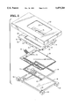
- FIG. 5 is an exploded view, showing the upper housing of the hand-held terminal and various components of the shock mounting system.
- FIG. 6 is a perspective exploded view, viewed from below, showing the carrier and four shock absorbing members which are positioned on projections extending from the carrier.
- FIG. 7 is a perspective view, showing the carrier and the display mounted within a bezel which forms part of the shock mounting system.
- FIGS. 8 and 9 are fragmentary sectional views taken on lines 8--8 and 9--9 of FIG. 7,showing details of the mounting of the display and associated printed circuit boards and TAB connections.
- FIG. 10 is a fragmentary sectional view similar to FIG. 8, showing the manner in which additional shock absorbing members may be employed to minimize movement of the printed circuit boards which are connected to the display.
- a device which may be a hand-held business terminal, 20, comprising an upper housing 22 and a lower housing 24.
- the upper housing 22 includes an aperture 26 through which a display 28 may be viewed.
- the display 28 is a relatively fragile component, and is subject to damage if the business terminal is dropped or otherwise subjected to shock unless the display 28 is protected against such shock by suitable structure within the terminal 20. While the display 28 is shown as the component to be protected in the illustrated embodiment of the present invention, it will be recognized that other types of components subject to damage from shock could also be protected using the teaching of the present invention.
- the display 28 comprises two panes of glass 30 and 32 which are cemented or otherwise secured together, with a liquid crystal material located in a layer between the two panes of glass.
- a layer 34 of polarizing material Positioned above the two panes of glass and secured to the upper pane of glass 30 is a layer 34 of polarizing material, which may be made of a suitable plastic.
- a backing sheet 33 Secured to the lower pane of glass 32 is a backing sheet 33 (FIGS. 8-10) for the display 28.
- the lower pane of glass 32 of the display 28 extends slightly outward of the upper pane of glass 30 to form a base to which a plurality of tape automated bonding (TAB) or other suitable type of connectors 38 may be secured.
- TAB tape automated bonding
- the TAB connectors electrically couple the display glass panes, with captive liquid crystal material, through suitable connections, to a plurality of printed circuit boards 36, which provide necessary circuitry to operate the display 28.
- Drivers 40 for driving the display 28 are also mounted on the TAB connectors 38.
- a cable 42 provides necessary power and data inputs to the display 28.
- FIG. 5 Shown in FIG. 5 in an exploded view are the various elements of the assembly or module 29 which comprise the shock mounting system which protects the display 28.
- the gasket 44 is positioned around all edges of the glass of the display which would otherwise come into contact with surfaces of the supporting structure.
- the gasket 44 is slotted as shown at 46 along two sides to permit the TAB connections 40 and the printed circuit boards 38 to extend therethrough.
- the display 28 with gasket 44 mounted thereon is positioned within a carrier 48 which may suitably be molded from plastic material, and which provides torsional strength to the shock mounting system.
- the carrier 48 is provided on its underside with a plurality of ribs 50, 52, 54 and 56 (FIG. 6) which are molded into the carrier and which enhance its torsional strength to resist bending of the display 28 along the axes 12 and 14 shown in FIG. 3.
- a post 58 in one corner of the carrier 48 engages an aperture 60 formed on an extension of the gasket 44 when the display 28 and gasket 44 are positioned within the carrier 48 in order to maintain the parts in proper assembled relation.
- the carrier 48 also includes a projection 62 at each of its four corners.
- the shock grommets 64 effectively suspend the display within the housing of the terminal 20, controlling deceleration of the display 28 in all directions when subjected to mechanical shock in any direction.
- the assembled display 28, gasket 44 and carrier 48 fit within a cold formed metal bezel 68 having an aperture 70 through which the display 28 can be viewed, four downwardly extending walls 72 and a reinforcing groove 74 which compresses gasket 44.
- the bezel 68 is relatively weak in torsion, since a substantial portion of it is removed to provide a window through the display may be viewed, but provides beam strength to the system to resist bending along the axes 16 and 18 shown in FIG. 3.
- Cut-outs 76 in the walls 72 define tabs 78 which can be bent inwardly to retain the assembled display 28, gasket 44 and carrier 48 in position within the walls 72 of the bezel 68.
- the gasket 44 is put into compression when squeezed between the bezel 68 and the carrier 48.
- the shock gasket 44 prevents direct contact between the display 28 and the carrier 48 or the bezel 68, which reduces localized stress and bending of the display.
- the upper housing 22 is provided with four seats 80 which are positioned to receive the four shock members 64 when the module 29 comprising the display 28, the gasket 44, the carrier 48, the bezel 68 and the shock members or grommets 64 is placed within the upper housing 22 and retained there by metal plates (not shown).
- the display 28 is thus suspended in a position in which it is spaced from the walls of the upper housing 22. This suspension of the display 28 permits control of deceleration of the module comprising the display 28, the gasket 44, the carrier 48 and the bezel 68 in all directions when the terminal 20 is subjected to shock in any direction, as by a fall.
- the deceleration of the display can be effectively controlled.
- a clearance of 0.080 inch is provided between the display chassis and the inside surface of the wall of the upper housing 22, which distance is used to decelerate the display chassis.
- strain relief is provided between the TAB connections 38 and the glass panes 30, 32 of the display 28 and between said TAB connections and the printed circuit boards 36. It is imperative that these connections be strain relieved, because the high G forces developed during a shock loading will otherwise cause the connections to fail. Strain relief between the TAB connections 38 and the glass panes 30, 32 is provided by the shock gasket 44 when it is put into compression between the bezel 68 and the carrier 48.
- the connection between the TAB connections 38 and the printed circuit boards 36 is strain relieved by using an adhesive/sealant bond 82 (FIG. 8). Alternatively, additional solder pads 88 (FIG.
- solder pads 88 should be staggered or located in a multi-line formation, rather than in a single straight line, in order to optimize the strain relief which they provide.
- additional shock gaskets 84 and 86 may be positioned between the bezel 68 and the TAB connector 38, and between the carrier 48 and the printed circuit board 36. These additional gaskets help to control the deceleration of the printed circuit board and reduce the stress on the TAB connector.
Abstract
Description
Claims (26)
Priority Applications (2)
| Application Number | Priority Date | Filing Date | Title |
|---|---|---|---|
| US08/115,295 US5479285A (en) | 1993-09-01 | 1993-09-01 | Liquid crystal device with an isotropic shock mounting and gasket |
| JP6183191A JPH0783260A (en) | 1993-09-01 | 1994-08-04 | Isotropic shock-resistant assembly and assembling method thereof |
Applications Claiming Priority (1)
| Application Number | Priority Date | Filing Date | Title |
|---|---|---|---|
| US08/115,295 US5479285A (en) | 1993-09-01 | 1993-09-01 | Liquid crystal device with an isotropic shock mounting and gasket |
Publications (1)
| Publication Number | Publication Date |
|---|---|
| US5479285A true US5479285A (en) | 1995-12-26 |
Family
ID=22360442
Family Applications (1)
| Application Number | Title | Priority Date | Filing Date |
|---|---|---|---|
| US08/115,295 Expired - Lifetime US5479285A (en) | 1993-09-01 | 1993-09-01 | Liquid crystal device with an isotropic shock mounting and gasket |
Country Status (2)
| Country | Link |
|---|---|
| US (1) | US5479285A (en) |
| JP (1) | JPH0783260A (en) |
Cited By (108)
| Publication number | Priority date | Publication date | Assignee | Title |
|---|---|---|---|---|
| US5550324A (en) * | 1995-02-23 | 1996-08-27 | Fluke Corporation | Environmental sealing system for electronic instruments |
| WO1996029787A1 (en) * | 1995-03-22 | 1996-09-26 | Amsc Subsidiary Corporation | Mobile communicator bracing system |
| US5568357A (en) * | 1994-06-15 | 1996-10-22 | Metanetics Corporation | Display support having cradled damping caps for floating core shock absorption |
| US5570267A (en) * | 1995-07-12 | 1996-10-29 | Ma; Hsi-Kuang | Flat display module |
| US5594953A (en) * | 1994-01-28 | 1997-01-14 | Amsc Subsidiary Corporation | Mobile communicator system |
| US5825613A (en) * | 1997-03-06 | 1998-10-20 | Strongarm Designs, Inc. | Tilting display with cabinet seal |
| GB2327288A (en) * | 1997-07-12 | 1999-01-20 | Motorola Israel Ltd | Liquid crystal display assembly |
| EP0915359A2 (en) * | 1997-11-07 | 1999-05-12 | Mitsubishi Denki Kabushiki Kaisha | Display device |
| US5940153A (en) * | 1998-04-03 | 1999-08-17 | Motorola, Inc. | Display assembly having LCD and seal captured between interlocking lens cover and lightpipe |
| EP0947910A2 (en) | 1998-04-03 | 1999-10-06 | Samsung Electronics Co., Ltd. | A palm-sized computer assembly |
| US5999238A (en) * | 1996-08-28 | 1999-12-07 | Kabushiki Kaisha Toshiba | Filter device and backlight device |
| US6002582A (en) * | 1998-01-05 | 1999-12-14 | Dell U.S.A., L.P. | Adapter for various LCD sizes in a computer |
| US6016423A (en) * | 1994-01-28 | 2000-01-18 | Amsc Subsidiary Corporation | Mobile communicator system |
| US6094340A (en) * | 1997-05-27 | 2000-07-25 | Samsung Electronics Co., Ltd. | Method and apparatus of coupling liquid crystal panel for liquid crystal display |
| US6144552A (en) * | 1999-04-26 | 2000-11-07 | Emc Corporation | Handheld computer system |
| US6151207A (en) * | 1997-11-28 | 2000-11-21 | Samsung Electronics Co., Ltd. | Structure for protecting electronic systems from impact and portable computer with such a structure |
| US6152550A (en) * | 1998-02-06 | 2000-11-28 | Matsushita Electric Industrial Co., Ltd. | Protective sheet mount structure for display |
| EP0880049B1 (en) * | 1997-04-08 | 2001-01-17 | Lg Electronics Inc. | Computer comprising a LCD device |
| US6186400B1 (en) * | 1998-03-20 | 2001-02-13 | Symbol Technologies, Inc. | Bar code reader with an integrated scanning component module mountable on printed circuit board |
| US6283438B1 (en) * | 1998-03-13 | 2001-09-04 | Matsushita Electric Industrial Co., Ltd. | Shock absorbing holder and information processor having same |
| US6330045B1 (en) * | 1999-02-16 | 2001-12-11 | Nec Corporation | Liquid-crystal display device with a gasket for controlling thermal gradient within the device |
| US6352322B1 (en) * | 1997-08-21 | 2002-03-05 | Citizen Watch Co., Ltd. | Portable liquid crystal display device |
| US6411352B1 (en) * | 1998-08-10 | 2002-06-25 | Lg. Philips Lcd Co., Ltd. | Slim liquid crystal display device |
| US20020080299A1 (en) * | 1997-04-08 | 2002-06-27 | Yun Hee Young | Computer having liquid crystal display |
| US6496362B2 (en) * | 2001-05-14 | 2002-12-17 | Iomega Corporation | Method and apparatus for protecting a hard disk drive from shock |
| WO2003010645A2 (en) * | 2001-07-25 | 2003-02-06 | Intergraph Hardware Technologies Company | Locally isolated ruggedized computer system and monitor |
| US20030037269A1 (en) * | 2001-05-25 | 2003-02-20 | Baker William P. | Method and apparatus for managing power consumption on a bus |
| US6532152B1 (en) * | 1998-11-16 | 2003-03-11 | Intermec Ip Corp. | Ruggedized hand held computer |
| US6587166B1 (en) * | 1998-08-26 | 2003-07-01 | Samsung Electronics Co., Ltd. | Liquid crystal display module and an assembly method therefor |
| WO2003067315A1 (en) * | 2002-02-07 | 2003-08-14 | Robert Bosch Gmbh | Fixing means for fixing a display and device comprising fixing means of this type |
| US20030169396A1 (en) * | 2000-08-25 | 2003-09-11 | Stephane Alric | Mechanical maintaining system for a device with a substantially flat element, in particular for liquid crystal display device |
| US6624979B1 (en) | 2000-06-09 | 2003-09-23 | Iomega Corporation | Method and apparatus for parking and releasing a magnetic head |
| US6628474B1 (en) | 2000-06-09 | 2003-09-30 | Iomega Corporation | Method and apparatus for electrostatic discharge protection in a removable cartridge |
| US6633445B1 (en) | 2000-06-09 | 2003-10-14 | Iomega Corporation | Method and apparatus for electrically coupling components in a removable cartridge |
| US6654077B1 (en) | 2000-01-18 | 2003-11-25 | Aurora Systems, Inc. | Precision surface mount for a display device |
| US20030227581A1 (en) * | 2002-06-11 | 2003-12-11 | Samsung Electronics, Co., Ltd. | Display apparatus |
| US20040037996A1 (en) * | 2002-08-21 | 2004-02-26 | Monson Robert James | Console display mounting system |
| US6717762B1 (en) | 2000-06-09 | 2004-04-06 | Iomega Corporation | Method and apparatus for making a drive compatible with a removable cartridge |
| US20040066618A1 (en) * | 2002-08-01 | 2004-04-08 | Layton Michael R. | Shock-resistant enclosure |
| US20040156192A1 (en) * | 2001-06-15 | 2004-08-12 | Apple Computer, Inc. | Active enclosure for computing device |
| US6779067B2 (en) | 2001-05-14 | 2004-08-17 | Iomega Corporation | Method and apparatus for providing extended functionality for a bus |
| US6781782B2 (en) | 2000-12-21 | 2004-08-24 | Iomega Corporation | Method and apparatus for saving calibration parameters for a removable cartridge |
| EP1453281A1 (en) * | 2003-02-27 | 2004-09-01 | Sony Ericsson Mobile Communications AB | Compact display module |
| WO2004077800A1 (en) * | 2003-02-27 | 2004-09-10 | Sony Ericsson Mobile Communications Ab | Compact display module |
| US20040182979A1 (en) * | 2001-06-28 | 2004-09-23 | Siemens Ag | Retaining device for the floating mounting of a flat screen and electronic display device comprising a flat screen and a retaining device |
| US20040189886A1 (en) * | 2003-03-28 | 2004-09-30 | Chia-Lin Chang | Structure for absorbing the shock |
| US6838810B1 (en) | 1997-03-21 | 2005-01-04 | Chunghwa Picture Tubes, Ltd. | Flat-panel display mounting system for portable computer |
| WO2005000114A2 (en) * | 2003-06-03 | 2005-01-06 | Bayer Healthcare Llc | Portable medical diagnostic apparatus |
| US6844902B2 (en) * | 1999-12-27 | 2005-01-18 | Kabushiki Kaisha Advanced Display | Liquid crystal display device having pawl portions and hinge members |
| US20050062899A1 (en) * | 2003-09-19 | 2005-03-24 | Norihisa Fukayama | Display device |
| US20050094052A1 (en) * | 2003-09-19 | 2005-05-05 | Shinji Sakurai | Electro-optical device, electronic apparatus, and method of producing electro-optical device |
| US20050168930A1 (en) * | 1998-10-23 | 2005-08-04 | Kim Jong H. | Portable computer and method for mounting a flat panel display device thereon |
| US20050185424A1 (en) * | 2004-02-20 | 2005-08-25 | Yi-Shiuan Tsai | Backlight module |
| US20050270733A1 (en) * | 1999-05-14 | 2005-12-08 | Apple Computer, Inc. | Display housing for computing device |
| US20060061859A1 (en) * | 2004-09-03 | 2006-03-23 | Research In Motion Limited | Shock resistant mounting for small display screen |
| US20060066772A1 (en) * | 2004-09-27 | 2006-03-30 | Kabushiki Kaisha Toshiba | Display apparatus and information terminal |
| KR100555851B1 (en) * | 1998-12-04 | 2006-05-02 | 삼성전자주식회사 | LCD monitor device |
| US20060098392A1 (en) * | 2004-11-08 | 2006-05-11 | Shinji Sakurai | Electro-optical device and electronic apparatus |
| US7092251B1 (en) * | 2005-01-06 | 2006-08-15 | Western Digital Technologies, Inc. | Vibration isolating disk drive receiving stations and chassis used in the manufacture and/or testing of hard disk drives |
| US20060204781A1 (en) * | 2003-02-14 | 2006-09-14 | Kenzo Takei | Component for optical device |
| WO2006100178A1 (en) * | 2005-03-23 | 2006-09-28 | Thomson Licensing | Flat screen display device comprising points for fixing said screen to a cabinet |
| US20060229502A1 (en) * | 2003-06-03 | 2006-10-12 | Bayer Healthcare Llc | Portable medical diagnostic apparatus |
| US7170741B2 (en) | 1998-11-11 | 2007-01-30 | Lg. Philips Lcd Co., Ltd. | Portable computer and method for mounting a flat panel display device module |
| US20070121026A1 (en) * | 2005-11-25 | 2007-05-31 | Innolux Display Corp. | Liquid crystal display with high-profile elastic gasket |
| US20080112125A1 (en) * | 2006-11-09 | 2008-05-15 | Imation Corp. | Portable hard drive with axis specific shock absorption |
| CN100403219C (en) * | 2004-09-28 | 2008-07-16 | 株式会社东芝 | Electronic apparatus |
| US20080227308A1 (en) * | 2007-03-14 | 2008-09-18 | Shigeyuki Fujii | Touch panel |
| US7443388B1 (en) | 1999-05-14 | 2008-10-28 | Apple Inc. | Housing for a computing device |
| US7452098B2 (en) | 2001-06-15 | 2008-11-18 | Apple Inc. | Active enclosure for computing device |
| US7492421B1 (en) | 1997-07-03 | 2009-02-17 | Lg Display Co., Ltd. | Case for liquid crystal display |
| US20090086119A1 (en) * | 2007-09-28 | 2009-04-02 | Hitachi Ltd. | Image displaying apparatus |
| WO2009123696A3 (en) * | 2008-03-31 | 2010-01-14 | Corning Incorporated | Bezel packaging for sealed glass assemblies and a glass assembly therefor |
| US20100025942A1 (en) * | 2008-07-29 | 2010-02-04 | Psion Teklogix Inc. | Sealing system and seal component for a display assembly of a portable device |
| US20100097539A1 (en) * | 2008-10-17 | 2010-04-22 | Au Optronics Corporation | Flat Panel Display and Method for Fabricating the Same |
| US20100134704A1 (en) * | 2008-12-02 | 2010-06-03 | Au Optronics Corp. | Display device |
| US7786559B2 (en) | 2006-11-08 | 2010-08-31 | Corning Incorporated | Bezel packaging of frit-sealed OLED devices |
| US20100265431A1 (en) * | 2009-04-21 | 2010-10-21 | Shenzhen Futaihong Precision Industry Co., Ltd. | Protecting module and portable electronic device using the same |
| US20100285850A1 (en) * | 2009-05-07 | 2010-11-11 | Todd Robert Paleczny | Gasket for a mobile device having a touch sensitive display |
| US7868905B2 (en) | 2001-06-15 | 2011-01-11 | Apple Inc. | Active enclosure for computing device |
| EP2372503A1 (en) * | 2008-12-26 | 2011-10-05 | Nissha Printing Co., Ltd. | Protection panel with touch input function for electronic device display window, and method for manufacturing same |
| US20110261001A1 (en) * | 2010-04-23 | 2011-10-27 | Jin Liu | Apparatus and method for impact resistant touchscreen display module |
| US20110261513A1 (en) * | 2010-04-22 | 2011-10-27 | Gihoon Tho | Mobile display device and window manufacturing method for the display device |
| US20110261528A1 (en) * | 2010-04-23 | 2011-10-27 | Dinesh Gandhi | Shock mount for circuit board |
| US20110261510A1 (en) * | 2010-04-23 | 2011-10-27 | Jin Liu | Display Assembly for a Portable Module |
| DE10296965B4 (en) * | 2001-06-26 | 2012-01-26 | Keba Ag | Portable device with at least one optical output device for at least visualizing process data of a machine, a robot or a technical process |
| CN101140811B (en) * | 2006-09-08 | 2012-03-14 | 罗伯特·博世有限公司 | Manual testing device |
| US20120147532A1 (en) * | 2010-12-14 | 2012-06-14 | Hon Hai Precision Industry Co., Ltd. | Electronic device housing and manufacturing method thereof |
| CN102749962A (en) * | 2011-04-19 | 2012-10-24 | 研祥智能科技股份有限公司 | Display module and rugged tablet personal computer thereof |
| TWI381787B (en) * | 2009-08-21 | 2013-01-01 | Htc Corp | Casing assembly of handheld device and manufacturing method thereof |
| US8373980B2 (en) | 2010-10-22 | 2013-02-12 | Explore Technologies Corp. | System for mounting a display to a computer |
| US8403136B1 (en) * | 2012-04-16 | 2013-03-26 | Aaeon Technology Inc. | Waterproof, shockproof container for handheld electronic device |
| US8508927B2 (en) | 2010-09-24 | 2013-08-13 | Research In Motion Limited | Gasket and display assembly for an electronic mobile device |
| TWI407891B (en) * | 2009-04-30 | 2013-09-01 | Fih Hong Kong Ltd | Protecting module and portable electronic device using the same |
| WO2014130986A1 (en) * | 2013-02-25 | 2014-08-28 | Motorola Mobility Llc | Electronic device having a display and method of manufacture |
| WO2014130198A1 (en) * | 2013-02-25 | 2014-08-28 | Motorola Mobility Llc | Apparatus and methods for accommodating a display in an electronic device |
| US20150131022A1 (en) * | 2013-11-13 | 2015-05-14 | Shenzhen China Star Optoelectronics Technology Co. Ltd. | Multiple display monitor |
| US9081428B2 (en) | 2010-04-23 | 2015-07-14 | Psion Inc. | Apparatus and method for impact resistant touchscreen display module |
| CN105739153A (en) * | 2016-04-15 | 2016-07-06 | 珠海格力电器股份有限公司 | Liquid crystal display device and remote controller |
| EP2923235A4 (en) * | 2012-11-21 | 2016-08-03 | Nexeon Energy Solutions LLC | Energy-efficient film |
| US9484001B2 (en) | 2013-12-23 | 2016-11-01 | Google Technology Holdings LLC | Portable electronic device controlling diffuse light source to emit light approximating color of object of user interest |
| CN102749962B (en) * | 2011-04-19 | 2016-12-14 | 研祥智能科技股份有限公司 | Display apparatus module and reinforcing panel computer thereof |
| US20170097659A1 (en) * | 2014-06-26 | 2017-04-06 | Kyocera Corporation | Electronic apparatus |
| US20170118866A1 (en) * | 2013-09-03 | 2017-04-27 | Lg Electronics Inc. | Mobile terminal and manufacturing method for heat spreader module |
| US9674922B2 (en) | 2013-03-14 | 2017-06-06 | Google Technology Holdings LLC | Display side edge assembly and mobile device including same |
| US9875008B2 (en) | 2011-11-16 | 2018-01-23 | Google Llc | Display device, corresponding systems, and methods therefor |
| EP3226070A4 (en) * | 2014-11-25 | 2018-07-11 | Boe Technology Group Co. Ltd. | Liquid crystal module and display device |
| US20180287799A1 (en) * | 2014-11-12 | 2018-10-04 | Erik Jan Harkes | A method of transmitting data, a mobile electronic device, an electronic token, a software services platform and a computer program product |
| WO2022189624A1 (en) * | 2021-03-12 | 2022-09-15 | Continental Automotive Technologies GmbH | Electronic device |
Families Citing this family (5)
| Publication number | Priority date | Publication date | Assignee | Title |
|---|---|---|---|---|
| JP3043710B2 (en) | 1997-08-04 | 2000-05-22 | キヤノン株式会社 | A support structure for supporting a panel, a panel device having a panel and a support structure for supporting the panel, and an image forming apparatus using the panel device |
| TWI315014B (en) * | 2005-12-26 | 2009-09-21 | Au Optronics Corporatio | Backlight module of flat panel display |
| JP2009086276A (en) * | 2007-09-28 | 2009-04-23 | Hitachi Ltd | Image display apparatus and support member structure thereof |
| JP5097851B2 (en) * | 2011-11-08 | 2012-12-12 | 株式会社日立製作所 | Power supply substrate for thin display device and thin display device using the same |
| KR102175818B1 (en) * | 2014-06-10 | 2020-11-09 | 삼성디스플레이 주식회사 | Liquid crystal display |
Citations (24)
| Publication number | Priority date | Publication date | Assignee | Title |
|---|---|---|---|---|
| US3952152A (en) * | 1974-10-29 | 1976-04-20 | Teletype Corporation | CRT shield |
| US4063289A (en) * | 1976-11-18 | 1977-12-13 | Tektronix, Inc. | Cathode ray tube mounting means including lighting means and camera-connecting means |
| US4246613A (en) * | 1979-01-10 | 1981-01-20 | Delta Data Systems Corporation | Anti-glare screen with electromagnetic interference rejection |
| US4381421A (en) * | 1980-07-01 | 1983-04-26 | Tektronix, Inc. | Electromagnetic shield for electronic equipment |
| US4614404A (en) * | 1984-05-24 | 1986-09-30 | Laverne Greene | Electrically and manually operated mirror |
| US4652932A (en) * | 1984-04-10 | 1987-03-24 | Citizen Watch Co., Ltd. | Liquid crystal display television receiver |
| US4831211A (en) * | 1988-06-08 | 1989-05-16 | Rockwell International Corporation | EMI/RFI sealed microphonics isolation apparatus and methods |
| US4898555A (en) * | 1989-03-23 | 1990-02-06 | Bell & Howell Publication Systems Company | Display screen bezel and assembly method |
| JPH0284617A (en) * | 1988-09-21 | 1990-03-26 | Matsushita Electric Ind Co Ltd | Liquid crystal display device holding device |
| US4958889A (en) * | 1989-03-06 | 1990-09-25 | Dynabook Technologies Corporation | Three-position closure panel |
| US4979636A (en) * | 1989-06-12 | 1990-12-25 | Grid Systems Corporation | Housing assembly fastening |
| US5002368A (en) * | 1989-05-31 | 1991-03-26 | Poqet Computer Corporation | Liquid crystal display mounting structure |
| US5021763A (en) * | 1990-02-01 | 1991-06-04 | Obear Robert F | Environment protected industrial microcomputer |
| US5036313A (en) * | 1989-08-25 | 1991-07-30 | Micronics Computers, Inc. | Portable computer with improved assembly design |
| US5084757A (en) * | 1990-06-26 | 1992-01-28 | Digital Equipment Corporation | Method and apparatus for mounting a cathode ray tube to minimize tube shift and respect to a bezel |
| US5145434A (en) * | 1991-06-26 | 1992-09-08 | Digital Equipment Corporation | Video display device and method of mounting a cathode ray tube in a cabinet of a video display device |
| US5150231A (en) * | 1989-12-29 | 1992-09-22 | Canon Kabushiki Kaisha | Impact resistant ferroelectric liquid crystal apparatus |
| US5164542A (en) * | 1991-08-02 | 1992-11-17 | Tusk, Inc. | Composite housing for a computer system |
| US5182660A (en) * | 1990-08-03 | 1993-01-26 | Rohm Co., Ltd. | Back-light type liquid crystal display |
| JPH05100215A (en) * | 1991-10-08 | 1993-04-23 | Seiko Epson Corp | Structure of liquid crystal display device |
| US5243453A (en) * | 1990-03-02 | 1993-09-07 | Hitachi, Ltd. | Anti-moisture structures for use with a liquid crystal display |
| US5363277A (en) * | 1991-12-20 | 1994-11-08 | Rohm Co., Ltd. | Structure and method for mounting semiconductor device |
| US5422751A (en) * | 1992-10-14 | 1995-06-06 | Apple Computer, Inc. | Liquid crystal display assembly employing front bezel, frame holding liquid crystal cell attached to bezel, and light source and back plate attached to bezel |
| US5432626A (en) * | 1992-03-12 | 1995-07-11 | Hitachi, Ltd. | Liquid crystal display device with shield casing connected to frame holding the display above lower casing holding light source |
-
1993
- 1993-09-01 US US08/115,295 patent/US5479285A/en not_active Expired - Lifetime
-
1994
- 1994-08-04 JP JP6183191A patent/JPH0783260A/en active Pending
Patent Citations (24)
| Publication number | Priority date | Publication date | Assignee | Title |
|---|---|---|---|---|
| US3952152A (en) * | 1974-10-29 | 1976-04-20 | Teletype Corporation | CRT shield |
| US4063289A (en) * | 1976-11-18 | 1977-12-13 | Tektronix, Inc. | Cathode ray tube mounting means including lighting means and camera-connecting means |
| US4246613A (en) * | 1979-01-10 | 1981-01-20 | Delta Data Systems Corporation | Anti-glare screen with electromagnetic interference rejection |
| US4381421A (en) * | 1980-07-01 | 1983-04-26 | Tektronix, Inc. | Electromagnetic shield for electronic equipment |
| US4652932A (en) * | 1984-04-10 | 1987-03-24 | Citizen Watch Co., Ltd. | Liquid crystal display television receiver |
| US4614404A (en) * | 1984-05-24 | 1986-09-30 | Laverne Greene | Electrically and manually operated mirror |
| US4831211A (en) * | 1988-06-08 | 1989-05-16 | Rockwell International Corporation | EMI/RFI sealed microphonics isolation apparatus and methods |
| JPH0284617A (en) * | 1988-09-21 | 1990-03-26 | Matsushita Electric Ind Co Ltd | Liquid crystal display device holding device |
| US4958889A (en) * | 1989-03-06 | 1990-09-25 | Dynabook Technologies Corporation | Three-position closure panel |
| US4898555A (en) * | 1989-03-23 | 1990-02-06 | Bell & Howell Publication Systems Company | Display screen bezel and assembly method |
| US5002368A (en) * | 1989-05-31 | 1991-03-26 | Poqet Computer Corporation | Liquid crystal display mounting structure |
| US4979636A (en) * | 1989-06-12 | 1990-12-25 | Grid Systems Corporation | Housing assembly fastening |
| US5036313A (en) * | 1989-08-25 | 1991-07-30 | Micronics Computers, Inc. | Portable computer with improved assembly design |
| US5150231A (en) * | 1989-12-29 | 1992-09-22 | Canon Kabushiki Kaisha | Impact resistant ferroelectric liquid crystal apparatus |
| US5021763A (en) * | 1990-02-01 | 1991-06-04 | Obear Robert F | Environment protected industrial microcomputer |
| US5243453A (en) * | 1990-03-02 | 1993-09-07 | Hitachi, Ltd. | Anti-moisture structures for use with a liquid crystal display |
| US5084757A (en) * | 1990-06-26 | 1992-01-28 | Digital Equipment Corporation | Method and apparatus for mounting a cathode ray tube to minimize tube shift and respect to a bezel |
| US5182660A (en) * | 1990-08-03 | 1993-01-26 | Rohm Co., Ltd. | Back-light type liquid crystal display |
| US5145434A (en) * | 1991-06-26 | 1992-09-08 | Digital Equipment Corporation | Video display device and method of mounting a cathode ray tube in a cabinet of a video display device |
| US5164542A (en) * | 1991-08-02 | 1992-11-17 | Tusk, Inc. | Composite housing for a computer system |
| JPH05100215A (en) * | 1991-10-08 | 1993-04-23 | Seiko Epson Corp | Structure of liquid crystal display device |
| US5363277A (en) * | 1991-12-20 | 1994-11-08 | Rohm Co., Ltd. | Structure and method for mounting semiconductor device |
| US5432626A (en) * | 1992-03-12 | 1995-07-11 | Hitachi, Ltd. | Liquid crystal display device with shield casing connected to frame holding the display above lower casing holding light source |
| US5422751A (en) * | 1992-10-14 | 1995-06-06 | Apple Computer, Inc. | Liquid crystal display assembly employing front bezel, frame holding liquid crystal cell attached to bezel, and light source and back plate attached to bezel |
Cited By (207)
| Publication number | Priority date | Publication date | Assignee | Title |
|---|---|---|---|---|
| US5594953A (en) * | 1994-01-28 | 1997-01-14 | Amsc Subsidiary Corporation | Mobile communicator system |
| US5613223A (en) * | 1994-01-28 | 1997-03-18 | Amsc Subsidiary Corporation | Mobile communicator bracing system |
| US6016423A (en) * | 1994-01-28 | 2000-01-18 | Amsc Subsidiary Corporation | Mobile communicator system |
| US5568357A (en) * | 1994-06-15 | 1996-10-22 | Metanetics Corporation | Display support having cradled damping caps for floating core shock absorption |
| US5550324A (en) * | 1995-02-23 | 1996-08-27 | Fluke Corporation | Environmental sealing system for electronic instruments |
| WO1996029787A1 (en) * | 1995-03-22 | 1996-09-26 | Amsc Subsidiary Corporation | Mobile communicator bracing system |
| US5570267A (en) * | 1995-07-12 | 1996-10-29 | Ma; Hsi-Kuang | Flat display module |
| US5999238A (en) * | 1996-08-28 | 1999-12-07 | Kabushiki Kaisha Toshiba | Filter device and backlight device |
| US6163350A (en) * | 1996-08-28 | 2000-12-19 | Kabushiki Kaisha Toshiba | Filter device and backlight device, each filter sheet having only one holding portion which is bonded to a frame member |
| US5825613A (en) * | 1997-03-06 | 1998-10-20 | Strongarm Designs, Inc. | Tilting display with cabinet seal |
| US20060209504A1 (en) * | 1997-03-21 | 2006-09-21 | Michele Bovio | Flat-panel display mounting system for portable computer |
| US20050078439A1 (en) * | 1997-03-21 | 2005-04-14 | Michele Bovio | Flat-panel display mounting system for portable computer |
| US20050088810A1 (en) * | 1997-03-21 | 2005-04-28 | Michele Bovio | Flat-panel display mounting system for portable computer |
| US20050082961A1 (en) * | 1997-03-21 | 2005-04-21 | Michele Bovio | Flat-panel display mounting system for portable computer |
| US20050088075A1 (en) * | 1997-03-21 | 2005-04-28 | Michele Bovio | Flat-panel display mounting system for portable computer |
| US6838810B1 (en) | 1997-03-21 | 2005-01-04 | Chunghwa Picture Tubes, Ltd. | Flat-panel display mounting system for portable computer |
| US20060198091A1 (en) * | 1997-03-21 | 2006-09-07 | Michele Bovio | Flat-panel display mounting system for portable computer |
| US20060198090A1 (en) * | 1997-03-21 | 2006-09-07 | Michele Bovio | Flat-panel display mounting system for portable computer |
| US7310222B2 (en) | 1997-03-21 | 2007-12-18 | Chunghwa Picture Tubes, Ltd. | Flat-panel display mounting system for portable computer |
| US20060209503A1 (en) * | 1997-03-21 | 2006-09-21 | Michele Bovio | Flat-panel display mounting system for portable computer |
| US7944522B2 (en) | 1997-04-08 | 2011-05-17 | Lg Display Co., Ltd. | Computer having liquid crystal display |
| EP0880049B1 (en) * | 1997-04-08 | 2001-01-17 | Lg Electronics Inc. | Computer comprising a LCD device |
| US20020080299A1 (en) * | 1997-04-08 | 2002-06-27 | Yun Hee Young | Computer having liquid crystal display |
| US7944517B2 (en) | 1997-04-08 | 2011-05-17 | Lg Display, Co., Ltd. | Computer having liquid crystal display |
| US6094340A (en) * | 1997-05-27 | 2000-07-25 | Samsung Electronics Co., Ltd. | Method and apparatus of coupling liquid crystal panel for liquid crystal display |
| US7492421B1 (en) | 1997-07-03 | 2009-02-17 | Lg Display Co., Ltd. | Case for liquid crystal display |
| GB2327288A (en) * | 1997-07-12 | 1999-01-20 | Motorola Israel Ltd | Liquid crystal display assembly |
| US6352322B1 (en) * | 1997-08-21 | 2002-03-05 | Citizen Watch Co., Ltd. | Portable liquid crystal display device |
| US6064453A (en) * | 1997-11-07 | 2000-05-16 | Mitsubishi Denki Kabushiki Kaisha | Display device |
| EP0915359A2 (en) * | 1997-11-07 | 1999-05-12 | Mitsubishi Denki Kabushiki Kaisha | Display device |
| EP0915359A3 (en) * | 1997-11-07 | 2001-01-03 | Mitsubishi Denki Kabushiki Kaisha | Display device |
| US6151207A (en) * | 1997-11-28 | 2000-11-21 | Samsung Electronics Co., Ltd. | Structure for protecting electronic systems from impact and portable computer with such a structure |
| US6002582A (en) * | 1998-01-05 | 1999-12-14 | Dell U.S.A., L.P. | Adapter for various LCD sizes in a computer |
| US6247768B1 (en) * | 1998-02-06 | 2001-06-19 | Matsushita Electric Industrial Co., Ltd. | Protective sheet mount structure for display |
| US6152550A (en) * | 1998-02-06 | 2000-11-28 | Matsushita Electric Industrial Co., Ltd. | Protective sheet mount structure for display |
| US6283438B1 (en) * | 1998-03-13 | 2001-09-04 | Matsushita Electric Industrial Co., Ltd. | Shock absorbing holder and information processor having same |
| US6186400B1 (en) * | 1998-03-20 | 2001-02-13 | Symbol Technologies, Inc. | Bar code reader with an integrated scanning component module mountable on printed circuit board |
| US6669097B2 (en) * | 1998-03-20 | 2003-12-30 | Symbol Technologies, Inc. | Bar code reader with an integrated scanning component module mountable on printed circuit board |
| EP0947910A2 (en) | 1998-04-03 | 1999-10-06 | Samsung Electronics Co., Ltd. | A palm-sized computer assembly |
| US5940153A (en) * | 1998-04-03 | 1999-08-17 | Motorola, Inc. | Display assembly having LCD and seal captured between interlocking lens cover and lightpipe |
| EP0947910A3 (en) * | 1998-04-03 | 2003-02-05 | Samsung Electronics Co., Ltd. | A palm-sized computer assembly |
| US6411352B1 (en) * | 1998-08-10 | 2002-06-25 | Lg. Philips Lcd Co., Ltd. | Slim liquid crystal display device |
| US7327430B2 (en) | 1998-08-26 | 2008-02-05 | Samsung Electronics Co., Ltd. | Liquid crystal display module and an assembly method therefor |
| US6587166B1 (en) * | 1998-08-26 | 2003-07-01 | Samsung Electronics Co., Ltd. | Liquid crystal display module and an assembly method therefor |
| US20080111942A1 (en) * | 1998-08-26 | 2008-05-15 | Lee Sang-Duk | Liquid crystal display module and an assembly method therefor |
| US7535537B2 (en) * | 1998-08-26 | 2009-05-19 | Samsung Electronics, Co., Ltd. | Liquid crystal display module and an assembly method therefor |
| US7885059B2 (en) | 1998-10-23 | 2011-02-08 | Lg Display Co., Ltd. | Portable computer and method for mounting a flat panel display device thereon |
| US7828616B2 (en) | 1998-10-23 | 2010-11-09 | Lg Display Co., Ltd. | Method of forming a portable computer having a flat panel display device |
| US7907399B2 (en) | 1998-10-23 | 2011-03-15 | Lg Display Co., Ltd. | Portable computer and method for mounting a flat panel display device thereon |
| US20050168930A1 (en) * | 1998-10-23 | 2005-08-04 | Kim Jong H. | Portable computer and method for mounting a flat panel display device thereon |
| US7864138B2 (en) | 1998-10-23 | 2011-01-04 | Lg Display Co., Ltd. | Portable computer and method for mounting a flat panel display device thereon |
| US7663871B2 (en) | 1998-11-11 | 2010-02-16 | Lg Display Co., Ltd. | Portable computer and method for mounting a flat panel display device module |
| US7170741B2 (en) | 1998-11-11 | 2007-01-30 | Lg. Philips Lcd Co., Ltd. | Portable computer and method for mounting a flat panel display device module |
| US6532152B1 (en) * | 1998-11-16 | 2003-03-11 | Intermec Ip Corp. | Ruggedized hand held computer |
| KR100555851B1 (en) * | 1998-12-04 | 2006-05-02 | 삼성전자주식회사 | LCD monitor device |
| US6330045B1 (en) * | 1999-02-16 | 2001-12-11 | Nec Corporation | Liquid-crystal display device with a gasket for controlling thermal gradient within the device |
| US6144552A (en) * | 1999-04-26 | 2000-11-07 | Emc Corporation | Handheld computer system |
| US7724509B2 (en) | 1999-05-14 | 2010-05-25 | Apple Inc. | Display housing for computing device |
| US7460362B2 (en) | 1999-05-14 | 2008-12-02 | Apple Inc. | Display housing for computing device |
| US7804487B1 (en) | 1999-05-14 | 2010-09-28 | Apple Inc. | Housing for a computing device |
| US20050270733A1 (en) * | 1999-05-14 | 2005-12-08 | Apple Computer, Inc. | Display housing for computing device |
| US7679893B2 (en) | 1999-05-14 | 2010-03-16 | Apple Inc. | Display housing for computing device |
| US20050270734A1 (en) * | 1999-05-14 | 2005-12-08 | Apple Computer, Inc. | Display housing for computing device |
| US8256913B2 (en) | 1999-05-14 | 2012-09-04 | Apple Inc. | Housing for a computing device |
| US8139349B2 (en) | 1999-05-14 | 2012-03-20 | Apple Inc. | Display housing for computing device |
| US7440264B2 (en) * | 1999-05-14 | 2008-10-21 | Apple Inc. | Display housing for computing device |
| US7443388B1 (en) | 1999-05-14 | 2008-10-28 | Apple Inc. | Housing for a computing device |
| US7006170B2 (en) * | 1999-12-27 | 2006-02-28 | Kabushiki Kaisha Advanced Display | Liquid crystal display device with strengthening cushion portion |
| US20050062901A1 (en) * | 1999-12-27 | 2005-03-24 | Kabushiki Kaisha Advanced Display | Liquid crystal display device |
| US6844902B2 (en) * | 1999-12-27 | 2005-01-18 | Kabushiki Kaisha Advanced Display | Liquid crystal display device having pawl portions and hinge members |
| US6654077B1 (en) | 2000-01-18 | 2003-11-25 | Aurora Systems, Inc. | Precision surface mount for a display device |
| US6628474B1 (en) | 2000-06-09 | 2003-09-30 | Iomega Corporation | Method and apparatus for electrostatic discharge protection in a removable cartridge |
| US6717762B1 (en) | 2000-06-09 | 2004-04-06 | Iomega Corporation | Method and apparatus for making a drive compatible with a removable cartridge |
| US6624979B1 (en) | 2000-06-09 | 2003-09-23 | Iomega Corporation | Method and apparatus for parking and releasing a magnetic head |
| US6633445B1 (en) | 2000-06-09 | 2003-10-14 | Iomega Corporation | Method and apparatus for electrically coupling components in a removable cartridge |
| US7131623B2 (en) * | 2000-08-25 | 2006-11-07 | Thales | Mechanical holdings system for a device with an appreciably flat element, particularly for a liquid crystal screen display device |
| US20030169396A1 (en) * | 2000-08-25 | 2003-09-11 | Stephane Alric | Mechanical maintaining system for a device with a substantially flat element, in particular for liquid crystal display device |
| US6781782B2 (en) | 2000-12-21 | 2004-08-24 | Iomega Corporation | Method and apparatus for saving calibration parameters for a removable cartridge |
| US6779067B2 (en) | 2001-05-14 | 2004-08-17 | Iomega Corporation | Method and apparatus for providing extended functionality for a bus |
| US6496362B2 (en) * | 2001-05-14 | 2002-12-17 | Iomega Corporation | Method and apparatus for protecting a hard disk drive from shock |
| US6901525B2 (en) | 2001-05-25 | 2005-05-31 | Iomega Corporation | Method and apparatus for managing power consumption on a bus |
| US20030037269A1 (en) * | 2001-05-25 | 2003-02-20 | Baker William P. | Method and apparatus for managing power consumption on a bus |
| USRE41495E1 (en) | 2001-05-25 | 2010-08-10 | Baker William P | Method and apparatus for managing power consumption on a bus |
| US20040156192A1 (en) * | 2001-06-15 | 2004-08-12 | Apple Computer, Inc. | Active enclosure for computing device |
| US7728799B2 (en) | 2001-06-15 | 2010-06-01 | Apple Inc. | Active enclosure for computing device |
| US8029166B2 (en) | 2001-06-15 | 2011-10-04 | Apple Inc. | Active enclosure for computing device |
| US8148913B2 (en) | 2001-06-15 | 2012-04-03 | Apple Inc. | Active enclosure for computing device |
| US9797558B2 (en) | 2001-06-15 | 2017-10-24 | Apple Inc. | Active enclosure for computing device |
| US8395330B2 (en) | 2001-06-15 | 2013-03-12 | Apple Inc. | Active enclosure for computing device |
| US8264167B2 (en) | 2001-06-15 | 2012-09-11 | Apple Inc. | Active enclosure for computing device |
| US7452098B2 (en) | 2001-06-15 | 2008-11-18 | Apple Inc. | Active enclosure for computing device |
| US7766517B2 (en) | 2001-06-15 | 2010-08-03 | Apple Inc. | Active enclosure for computing device |
| US7868905B2 (en) | 2001-06-15 | 2011-01-11 | Apple Inc. | Active enclosure for computing device |
| US8729825B2 (en) | 2001-06-15 | 2014-05-20 | Apple Inc. | Active enclosure for computing device |
| US8033695B2 (en) | 2001-06-15 | 2011-10-11 | Apple Inc. | Active enclosure for computing device |
| DE10296965B4 (en) * | 2001-06-26 | 2012-01-26 | Keba Ag | Portable device with at least one optical output device for at least visualizing process data of a machine, a robot or a technical process |
| DE10296965B9 (en) * | 2001-06-26 | 2012-05-24 | Keba Ag | Portable device with at least one optical output device for at least visualizing process data of a machine, a robot or a technical process |
| US7267313B2 (en) * | 2001-06-28 | 2007-09-11 | Siemens Aktiengesellschaft | Retaining device for the floating mounting of a flat screen and electronic display device comprising a flat screen and a retaining device |
| US20040182979A1 (en) * | 2001-06-28 | 2004-09-23 | Siemens Ag | Retaining device for the floating mounting of a flat screen and electronic display device comprising a flat screen and a retaining device |
| WO2003010645A3 (en) * | 2001-07-25 | 2004-05-27 | Intergraph Hardware Tech Co | Locally isolated ruggedized computer system and monitor |
| WO2003010645A2 (en) * | 2001-07-25 | 2003-02-06 | Intergraph Hardware Technologies Company | Locally isolated ruggedized computer system and monitor |
| US6822855B2 (en) | 2001-07-25 | 2004-11-23 | Intergraph Hardware Technologies Company | Locally isolated ruggedized computer system and monitor |
| US20030030979A1 (en) * | 2001-07-25 | 2003-02-13 | Pressley Homer M. | Locally isolated ruggedized computer system and monitor |
| WO2003067315A1 (en) * | 2002-02-07 | 2003-08-14 | Robert Bosch Gmbh | Fixing means for fixing a display and device comprising fixing means of this type |
| US6894739B2 (en) | 2002-06-11 | 2005-05-17 | Samsung Electronics Co., Ltd. | Display apparatus having snap pin reinforcing member fastening mechanism |
| US20030227581A1 (en) * | 2002-06-11 | 2003-12-11 | Samsung Electronics, Co., Ltd. | Display apparatus |
| EP1372021A1 (en) * | 2002-06-11 | 2003-12-17 | Samsung Electronics Co., Ltd. | Display apparatus |
| US20040066618A1 (en) * | 2002-08-01 | 2004-04-08 | Layton Michael R. | Shock-resistant enclosure |
| US20040037996A1 (en) * | 2002-08-21 | 2004-02-26 | Monson Robert James | Console display mounting system |
| US6742776B2 (en) * | 2002-08-21 | 2004-06-01 | Robert James Monson | Console display mounting system |
| US7213800B2 (en) * | 2002-08-21 | 2007-05-08 | Lockheed Martin Corporation | Console display mounting system |
| US20060204781A1 (en) * | 2003-02-14 | 2006-09-14 | Kenzo Takei | Component for optical device |
| US20060146486A1 (en) * | 2003-02-27 | 2006-07-06 | Mikael Wikstrom | Compact display module |
| US7515401B2 (en) | 2003-02-27 | 2009-04-07 | Wikstroem Mikael | Compact display module |
| EP1453281A1 (en) * | 2003-02-27 | 2004-09-01 | Sony Ericsson Mobile Communications AB | Compact display module |
| WO2004077800A1 (en) * | 2003-02-27 | 2004-09-10 | Sony Ericsson Mobile Communications Ab | Compact display module |
| US20040189886A1 (en) * | 2003-03-28 | 2004-09-30 | Chia-Lin Chang | Structure for absorbing the shock |
| WO2005000114A2 (en) * | 2003-06-03 | 2005-01-06 | Bayer Healthcare Llc | Portable medical diagnostic apparatus |
| WO2005000114A3 (en) * | 2003-06-03 | 2005-06-09 | Bayer Healthcare Llc | Portable medical diagnostic apparatus |
| US20060229502A1 (en) * | 2003-06-03 | 2006-10-12 | Bayer Healthcare Llc | Portable medical diagnostic apparatus |
| US7319498B2 (en) * | 2003-09-19 | 2008-01-15 | Seiko Epson Corporation | Electro-optical device, electronic apparatus, and method of producing electro-optical device |
| US20050062899A1 (en) * | 2003-09-19 | 2005-03-24 | Norihisa Fukayama | Display device |
| US20050094052A1 (en) * | 2003-09-19 | 2005-05-05 | Shinji Sakurai | Electro-optical device, electronic apparatus, and method of producing electro-optical device |
| US20050185424A1 (en) * | 2004-02-20 | 2005-08-25 | Yi-Shiuan Tsai | Backlight module |
| US7004614B2 (en) * | 2004-02-20 | 2006-02-28 | Au Optronics Corp. | Backlight module |
| US7697275B2 (en) * | 2004-09-03 | 2010-04-13 | Research In Motion Limited | Shock resistant mounting for small display screen |
| US20060061859A1 (en) * | 2004-09-03 | 2006-03-23 | Research In Motion Limited | Shock resistant mounting for small display screen |
| US20060066772A1 (en) * | 2004-09-27 | 2006-03-30 | Kabushiki Kaisha Toshiba | Display apparatus and information terminal |
| CN100403219C (en) * | 2004-09-28 | 2008-07-16 | 株式会社东芝 | Electronic apparatus |
| US7728918B2 (en) * | 2004-11-08 | 2010-06-01 | Seiko Epson Corporation | Electro-optical device and electronic apparatus |
| US20060098392A1 (en) * | 2004-11-08 | 2006-05-11 | Shinji Sakurai | Electro-optical device and electronic apparatus |
| US7092251B1 (en) * | 2005-01-06 | 2006-08-15 | Western Digital Technologies, Inc. | Vibration isolating disk drive receiving stations and chassis used in the manufacture and/or testing of hard disk drives |
| FR2883657A1 (en) * | 2005-03-23 | 2006-09-29 | Thomson Licensing Sa | FLAT SCREEN DISPLAY DEVICE WITH SCREEN FASTENING POINTS TO A BOX |
| WO2006100178A1 (en) * | 2005-03-23 | 2006-09-28 | Thomson Licensing | Flat screen display device comprising points for fixing said screen to a cabinet |
| US20070121026A1 (en) * | 2005-11-25 | 2007-05-31 | Innolux Display Corp. | Liquid crystal display with high-profile elastic gasket |
| CN101140811B (en) * | 2006-09-08 | 2012-03-14 | 罗伯特·博世有限公司 | Manual testing device |
| US7786559B2 (en) | 2006-11-08 | 2010-08-31 | Corning Incorporated | Bezel packaging of frit-sealed OLED devices |
| US20080112125A1 (en) * | 2006-11-09 | 2008-05-15 | Imation Corp. | Portable hard drive with axis specific shock absorption |
| US7494358B2 (en) * | 2007-03-14 | 2009-02-24 | Panasonic Corporation | Touch panel |
| US20080227308A1 (en) * | 2007-03-14 | 2008-09-18 | Shigeyuki Fujii | Touch panel |
| US8576350B2 (en) | 2007-09-28 | 2013-11-05 | Hitachi Consumer Electronics Co., Ltd. | Image displaying apparatus |
| US8023062B2 (en) | 2007-09-28 | 2011-09-20 | Hitachi, Ltd. | Image display apparatus |
| US7924366B2 (en) | 2007-09-28 | 2011-04-12 | Hitachi, Ltd. | Image displaying apparatus |
| US7796206B2 (en) | 2007-09-28 | 2010-09-14 | Hitachi, Ltd. | Image displaying apparatus |
| US20090086119A1 (en) * | 2007-09-28 | 2009-04-02 | Hitachi Ltd. | Image displaying apparatus |
| CN102046900B (en) * | 2008-03-31 | 2014-06-04 | 康宁股份有限公司 | Bezel packaging for sealed glass assemblies and a glass assembly therefor |
| US8885116B2 (en) | 2008-03-31 | 2014-11-11 | Corning Incorporated | Bezel packaging for sealed glass assemblies and a glass assembly therefor |
| TWI404249B (en) * | 2008-03-31 | 2013-08-01 | Corning Inc | Bezel packaging for sealed glass assemblies and a glass assembly therefor |
| KR20150024920A (en) * | 2008-03-31 | 2015-03-09 | 코닝 인코포레이티드 | A bezel for packaging a sealed glass assembly |
| WO2009123696A3 (en) * | 2008-03-31 | 2010-01-14 | Corning Incorporated | Bezel packaging for sealed glass assemblies and a glass assembly therefor |
| US20110019351A1 (en) * | 2008-03-31 | 2011-01-27 | CORNING INCORPORATED a,New York Corporation | Bezel packaging for sealed glass assemblies and a glass assembly therefor |
| CN102046900A (en) * | 2008-03-31 | 2011-05-04 | 康宁股份有限公司 | Bezel packaging for sealed glass assemblies and a glass assembly therefor |
| EP2151735A2 (en) * | 2008-07-29 | 2010-02-10 | Psion Teklogix Inc. | Sealing system and seal component for a display assembly of a portable device |
| EP2151735A3 (en) * | 2008-07-29 | 2011-10-19 | Psion Inc. | Sealing system and seal component for a display assembly of a portable device |
| US20100025942A1 (en) * | 2008-07-29 | 2010-02-04 | Psion Teklogix Inc. | Sealing system and seal component for a display assembly of a portable device |
| US8184232B2 (en) * | 2008-10-17 | 2012-05-22 | Au Optronics Corporation | Flat panel display and method for fabricating the same |
| US20100097539A1 (en) * | 2008-10-17 | 2010-04-22 | Au Optronics Corporation | Flat Panel Display and Method for Fabricating the Same |
| US8189126B2 (en) * | 2008-12-02 | 2012-05-29 | Au Optronics Corp. | Display device |
| US20100134704A1 (en) * | 2008-12-02 | 2010-06-03 | Au Optronics Corp. | Display device |
| US8675147B2 (en) | 2008-12-26 | 2014-03-18 | Nissha Printing Co., Ltd. | Protection panel provided with touch input function for display window of electronic device, and manufacturing method therefor |
| EP2372503A4 (en) * | 2008-12-26 | 2012-05-23 | Nissha Printing | Protection panel with touch input function for electronic device display window, and method for manufacturing same |
| EP2372503A1 (en) * | 2008-12-26 | 2011-10-05 | Nissha Printing Co., Ltd. | Protection panel with touch input function for electronic device display window, and method for manufacturing same |
| US20100265431A1 (en) * | 2009-04-21 | 2010-10-21 | Shenzhen Futaihong Precision Industry Co., Ltd. | Protecting module and portable electronic device using the same |
| US8482697B2 (en) * | 2009-04-21 | 2013-07-09 | Shenzhen Futaihong Precision Industry Co., Ltd. | Protecting module and portable electronic device using the same |
| TWI407891B (en) * | 2009-04-30 | 2013-09-01 | Fih Hong Kong Ltd | Protecting module and portable electronic device using the same |
| US8260377B2 (en) | 2009-05-07 | 2012-09-04 | Research In Motion Limited | Gasket for a mobile device having a touch sensitive display |
| US20100285850A1 (en) * | 2009-05-07 | 2010-11-11 | Todd Robert Paleczny | Gasket for a mobile device having a touch sensitive display |
| TWI381787B (en) * | 2009-08-21 | 2013-01-01 | Htc Corp | Casing assembly of handheld device and manufacturing method thereof |
| US20110261513A1 (en) * | 2010-04-22 | 2011-10-27 | Gihoon Tho | Mobile display device and window manufacturing method for the display device |
| US8724297B2 (en) * | 2010-04-22 | 2014-05-13 | Lg Electronics Inc. | Mobile display device and window manufacturing method for the display device |
| US20110261528A1 (en) * | 2010-04-23 | 2011-10-27 | Dinesh Gandhi | Shock mount for circuit board |
| US8520373B2 (en) * | 2010-04-23 | 2013-08-27 | Psion Inc. | Display assembly for a portable module |
| US20110261001A1 (en) * | 2010-04-23 | 2011-10-27 | Jin Liu | Apparatus and method for impact resistant touchscreen display module |
| US9836091B2 (en) * | 2010-04-23 | 2017-12-05 | Psion, Inc. | Shock mount for circuit board |
| US9081428B2 (en) | 2010-04-23 | 2015-07-14 | Psion Inc. | Apparatus and method for impact resistant touchscreen display module |
| US20110261510A1 (en) * | 2010-04-23 | 2011-10-27 | Jin Liu | Display Assembly for a Portable Module |
| US8508927B2 (en) | 2010-09-24 | 2013-08-13 | Research In Motion Limited | Gasket and display assembly for an electronic mobile device |
| US8699216B2 (en) | 2010-10-22 | 2014-04-15 | Xplore Technologies Corp. | Computer with door-mounted electronics |
| US8373980B2 (en) | 2010-10-22 | 2013-02-12 | Explore Technologies Corp. | System for mounting a display to a computer |
| US8941981B2 (en) | 2010-10-22 | 2015-01-27 | Xplore Technologies Corp. | Computer with high intensity screen |
| US9383788B2 (en) | 2010-10-22 | 2016-07-05 | Xplore Technologies Corp. | Computer with high intensity screen |
| US8699220B2 (en) | 2010-10-22 | 2014-04-15 | Xplore Technologies Corp. | Computer with removable cartridge |
| US20120147532A1 (en) * | 2010-12-14 | 2012-06-14 | Hon Hai Precision Industry Co., Ltd. | Electronic device housing and manufacturing method thereof |
| US8456812B2 (en) * | 2010-12-14 | 2013-06-04 | Fu Tai Hua Industry (Shenzhen) Co., Ltd. | Electronic device housing and manufacturing method thereof |
| CN102749962A (en) * | 2011-04-19 | 2012-10-24 | 研祥智能科技股份有限公司 | Display module and rugged tablet personal computer thereof |
| CN102749962B (en) * | 2011-04-19 | 2016-12-14 | 研祥智能科技股份有限公司 | Display apparatus module and reinforcing panel computer thereof |
| US10387020B2 (en) | 2011-11-16 | 2019-08-20 | Google Technology Holdings LLC | Display device, corresponding systems, and methods therefor |
| US9875008B2 (en) | 2011-11-16 | 2018-01-23 | Google Llc | Display device, corresponding systems, and methods therefor |
| US8403136B1 (en) * | 2012-04-16 | 2013-03-26 | Aaeon Technology Inc. | Waterproof, shockproof container for handheld electronic device |
| EP2923235A4 (en) * | 2012-11-21 | 2016-08-03 | Nexeon Energy Solutions LLC | Energy-efficient film |
| WO2014130198A1 (en) * | 2013-02-25 | 2014-08-28 | Motorola Mobility Llc | Apparatus and methods for accommodating a display in an electronic device |
| US9550335B2 (en) | 2013-02-25 | 2017-01-24 | Google Technology Holdings LLC | Electronic device having a display and method of manufacture |
| WO2014130986A1 (en) * | 2013-02-25 | 2014-08-28 | Motorola Mobility Llc | Electronic device having a display and method of manufacture |
| US9616625B2 (en) | 2013-02-25 | 2017-04-11 | Google Technology Holdings LLC | Electronic device having a display and method of manufacture |
| US9622365B2 (en) | 2013-02-25 | 2017-04-11 | Google Technology Holdings LLC | Apparatus and methods for accommodating a display in an electronic device |
| US9674922B2 (en) | 2013-03-14 | 2017-06-06 | Google Technology Holdings LLC | Display side edge assembly and mobile device including same |
| US20170118866A1 (en) * | 2013-09-03 | 2017-04-27 | Lg Electronics Inc. | Mobile terminal and manufacturing method for heat spreader module |
| US9877412B2 (en) * | 2013-09-03 | 2018-01-23 | Lg Electronics Inc. | Mobile terminal and manufacturing method for heat spreader module |
| US20150131022A1 (en) * | 2013-11-13 | 2015-05-14 | Shenzhen China Star Optoelectronics Technology Co. Ltd. | Multiple display monitor |
| US9484001B2 (en) | 2013-12-23 | 2016-11-01 | Google Technology Holdings LLC | Portable electronic device controlling diffuse light source to emit light approximating color of object of user interest |
| US10175720B2 (en) * | 2014-06-26 | 2019-01-08 | Kyocera Corporation | Electronic apparatus |
| US20170097659A1 (en) * | 2014-06-26 | 2017-04-06 | Kyocera Corporation | Electronic apparatus |
| US20180287799A1 (en) * | 2014-11-12 | 2018-10-04 | Erik Jan Harkes | A method of transmitting data, a mobile electronic device, an electronic token, a software services platform and a computer program product |
| EP3226070A4 (en) * | 2014-11-25 | 2018-07-11 | Boe Technology Group Co. Ltd. | Liquid crystal module and display device |
| US10234714B2 (en) | 2014-11-25 | 2019-03-19 | Boe Technology Group Co., Ltd. | Liquid crystal module and display device |
| CN105739153A (en) * | 2016-04-15 | 2016-07-06 | 珠海格力电器股份有限公司 | Liquid crystal display device and remote controller |
| WO2022189624A1 (en) * | 2021-03-12 | 2022-09-15 | Continental Automotive Technologies GmbH | Electronic device |
Also Published As
| Publication number | Publication date |
|---|---|
| JPH0783260A (en) | 1995-03-28 |
Similar Documents
| Publication | Publication Date | Title |
|---|---|---|
| US5479285A (en) | Liquid crystal device with an isotropic shock mounting and gasket | |
| KR100264923B1 (en) | Liquid crystal display | |
| EP0469321B1 (en) | Back-light type liquid crystal display | |
| EP1589368B1 (en) | Liquid crystal display | |
| US6034751A (en) | Elastically deformed retaining members within retaining structure of LCD panel for electronic equipment | |
| EP0642087B1 (en) | Computer housing seal | |
| US5400160A (en) | Display means for apparatus with transparent panel fixed to LCD panel via elastic packing with ridges in zig zag pattern | |
| EP0642089B1 (en) | Computer display assembly | |
| KR19980079559A (en) | All-in-one display module | |
| US7006167B2 (en) | Fixing structure for an LCD panel | |
| JP2000194269A (en) | Structure of casing | |
| CN210722258U (en) | Display device | |
| JP3504024B2 (en) | Liquid crystal display | |
| US6195141B1 (en) | Hand-held control device | |
| US6587355B2 (en) | Liquid crystal display module with improved ground connection | |
| US20070115692A1 (en) | Liquid crystal display having liquid crystal panel secured using micro-adhesive units | |
| JPH11231294A (en) | Liquid crystal display module | |
| KR100319203B1 (en) | Lcd monitor apparatus | |
| JPH09265104A (en) | Liquid crystal display device | |
| JP3139601B2 (en) | Liquid crystal display | |
| JPH11230263A (en) | Member holding structure for electronic apparatus | |
| KR200171895Y1 (en) | Structure of LCD module for prevent impacting of TAB IC | |
| KR200226315Y1 (en) | Lcd fixing apparatus | |
| KR100891074B1 (en) | Structure for lamp housing of lcd | |
| CN210925292U (en) | Electronic device |
Legal Events
| Date | Code | Title | Description |
|---|---|---|---|
| AS | Assignment |
Owner name: NCR CORPORATION, OHIO Free format text: ASSIGNMENT OF ASSIGNORS INTEREST;ASSIGNOR:BURKE, RANDAL A.;REEL/FRAME:006799/0614 Effective date: 19930930 |
|
| CC | Certificate of correction | ||
| FPAY | Fee payment |
Year of fee payment: 4 |
|
| FPAY | Fee payment |
Year of fee payment: 8 |
|
| REMI | Maintenance fee reminder mailed | ||
| FEPP | Fee payment procedure |
Free format text: PETITION RELATED TO MAINTENANCE FEES GRANTED (ORIGINAL EVENT CODE: PMFG); ENTITY STATUS OF PATENT OWNER: LARGE ENTITY Free format text: PETITION RELATED TO MAINTENANCE FEES FILED (ORIGINAL EVENT CODE: PMFP); ENTITY STATUS OF PATENT OWNER: LARGE ENTITY |
|
| REIN | Reinstatement after maintenance fee payment confirmed | ||
| FP | Lapsed due to failure to pay maintenance fee |
Effective date: 20071226 |
|
| AS | Assignment |
Owner name: TAIWAN SEMICONDUCTOR MANUFACTURING COMPANY. LTD., Free format text: ASSIGNMENT OF ASSIGNORS INTEREST;ASSIGNOR:NCR CORPORATION;REEL/FRAME:021450/0507 Effective date: 20071115 |
|
| FPAY | Fee payment |
Year of fee payment: 12 |
|
| PRDP | Patent reinstated due to the acceptance of a late maintenance fee |
Effective date: 20081215 |
|
| STCF | Information on status: patent grant |
Free format text: PATENTED CASE |
|
| SULP | Surcharge for late payment |