US5399874A - Currency paper verification and denomination device having a clear image and a blurred image - Google Patents
Currency paper verification and denomination device having a clear image and a blurred image Download PDFInfo
- Publication number
- US5399874A US5399874A US08/182,462 US18246294A US5399874A US 5399874 A US5399874 A US 5399874A US 18246294 A US18246294 A US 18246294A US 5399874 A US5399874 A US 5399874A
- Authority
- US
- United States
- Prior art keywords
- paper
- light emitters
- image
- light
- pair
- Prior art date
- Legal status (The legal status is an assumption and is not a legal conclusion. Google has not performed a legal analysis and makes no representation as to the accuracy of the status listed.)
- Expired - Fee Related
Links
Images


Classifications
-
- G—PHYSICS
- G06—COMPUTING; CALCULATING OR COUNTING
- G06K—GRAPHICAL DATA READING; PRESENTATION OF DATA; RECORD CARRIERS; HANDLING RECORD CARRIERS
- G06K7/00—Methods or arrangements for sensing record carriers, e.g. for reading patterns
- G06K7/10—Methods or arrangements for sensing record carriers, e.g. for reading patterns by electromagnetic radiation, e.g. optical sensing; by corpuscular radiation
- G06K7/14—Methods or arrangements for sensing record carriers, e.g. for reading patterns by electromagnetic radiation, e.g. optical sensing; by corpuscular radiation using light without selection of wavelength, e.g. sensing reflected white light
-
- G—PHYSICS
- G06—COMPUTING; CALCULATING OR COUNTING
- G06K—GRAPHICAL DATA READING; PRESENTATION OF DATA; RECORD CARRIERS; HANDLING RECORD CARRIERS
- G06K7/00—Methods or arrangements for sensing record carriers, e.g. for reading patterns
- G06K7/10—Methods or arrangements for sensing record carriers, e.g. for reading patterns by electromagnetic radiation, e.g. optical sensing; by corpuscular radiation
- G06K2007/10485—Arrangement of optical elements
Definitions
- U.S. Pat. No. 4,524,276 entitled “Apparatus for Detecting a Security Thread Embedded in a Paper-Like Material” describes an infrared radiation source- and two infrared radiation detectors used to determine whether or not a security thread is embedded in the paper-like material and also to determine what the detected security material is made of.
- U.S. Pat. No. 4,980,569 describes a security paper verification device wherein optical means are arranged on opposing surfaces of the currency to determine the absence of any device on the surface of the currency paper while detecting the presence of the device within the currency. This is to prevent attaching counterfeit security threads to the outside surface of the currency paper to replicate genuine currency.
- U.S. Pat. No. 5,260,582 entitled “Security Paper Verification Device” describes optical, magnetic and capacitive sensors used in combination to determine currency authenticity.
- the dark inks and dyes used in printing U.S. federal reserve notes could provide difficult indication of a metallized security thread when such optical sensors are used, per se.
- U.S. Pat. No. 5,260,582 entitled “Security Paper Verification Device” describes an optical array arranged on both sides of a currency-receiving slot to determine whether the requisite security thread is present within the paper or on either surface.
- the device includes a microprocessor for calibration of the optical arrays.
- U.S. patent application Ser. No. 115,775 filed Sep. 3, 1993 entitled “Security Paper Verification Device” describes an optical array directed on one side of proffered currency paper to determine whether the requisite security thread is present within the paper or on the outer surface.
- the device includes a microprocessor for calibration of the optical arrays.
- one purpose of the invention is to describe an optical system and a correction algorithm that automatically compensates for image blurring caused by the motion of the scanners or the motion of the currency paper.
- Currency verification and denomination is made by means of separate pairs of photodiodes or lasers arranged on opposite sides of paper currency to excite corresponding phototransistors arranged on both sides thereof to determine the presence of the embedded security thread and to recognize the currency denomination.
- One of the photodiodes is focused onto the top surface of the currency paper while the other photodiode is slightly out of focus to provide a successive pair of clear and "blurred" images.
- the successive images provide indication of distortion caused by the motion of the paper or the motion of the photodiodes.
- Corrective phase diversity algorithms in the logic circuit remove both the intentional and unintentional blurrings to provide a clear image of the paper surface.
- the "signature" of the currency paper produced by the collective images is compared to stored values within the logic circuit to determine the presence of a security thread or watermark and to recognize the currency denomination.
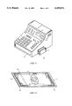
- FIG. 1 is a top perspective view of a currency receiver employing the verification device according to the invention
- FIG. 2 is a top perspective view of a U.S. currency bill employing a selectively metallized security thread
- FIG. 3 is a schematic representation of the optical circuit used with the device of FIGURE 1;
- FIG. 4 is a schematic representation of the logic circuit used with the optical circuit of FIG. 3.
- the verification device 14 can be used with a cash receiver such as the cash register 10 shown in FIG. 1 with the verification device attached to the cash register next to the cash drawer 13.
- the device could be in the form of a currency receiver as described in aforementioned U.S. Pat. No. 4,980,569 or in the form of the optical scanners described within aforementioned U.S. Patent Application.
- the verification device could provide electromagnetic as well as electromechanical interlock with the cash register so that the cash receiver drawer would not open in the event that counterfeit currency is detected within the verification device.
- the cash register is of the type using a keypad 11 and a display 12 to depict the price of goods being purchased as well as the denomination of the cash proffered by the customer.
- the same display could automatically register the denomination of the genuine currency within the verification device or, a green light-emitting diode 12A could provide visual indication of genuine currency whereas a red light-emitting diode 12B could indicate the presence of counterfeit currency.
- the outputs of the verification device could be connected in feedback relation with the cash register control circuit to count the change from the cash drawer to speed up the transaction, if so desired.
- FIG. 2 depicts one type of United States currency 15 consisting of a paper bill 16 having the portrait 17 of a United States president or the like and including a security thread 19 embedded therein.
- the bill is selectively color-printed to enhance the various features printed on both sides of the bill except for a border 16A and currency denomination indicia 18 which retain the basically "white” color of the currency paper prior to printing.
- the security thread extends transversely across the linear extent of the bill from the top to the bottom thereof.
- the security thread is introduced within the paper in the manner described within the aforementioned U.S. Pat. Nos. 4,652,015 and 4,761,205.
- the security thread is of the type consisting of a selectively metallized plastic film that is virtually invisible in reflected light and readily apparent under transmitted light. In order to verify the authenticity of such currency, a two-fold test must be performed, whereby the security thread must not be detected upon reflected light and, on the other hand, must be detected under transmitted light.
- three pairs of light emitting diodes or laser diodes D1,D2; D3,D4; D5,D6 are arranged along one side of the currency 15 to provide a reflected signal to corresponding phototransistors Q1,Q2; Q3,Q4; Q5,Q6.
- One diode in each pair is focused onto the top surface of the currency and the other diode in each pair is intentionally out of focus relative to the top surface by a predetermined aspect to provide intentional "blurring".
- Look-up tables are prepared for each currency denomination in accordance with the white paper, inks and dyes exhibited on the currency surface to provide the currency "signature" as described in the aforementioned U.S. Patent Applications.
- a file corresponding to the signatures is stored in look-up table format within the associated circuitry. Other signatures could also be generated for banknotes, travelers' checks and the like.
- a second algorithm is used to read the test file generated by the test image and to correlate the test image array with the reference array and identify which of the reference arrays matches the test array for denomination indication.
- a compensation algorithm provides filtering to discount data bits which may not correspond exactly to the stored data to compensate for fading effects as well as slight printing offsets. The intentional blurring is used to reduce the error incident in the focussed signals by means of the auto-correlation algorithm described within U.S. Pat. No. 4,309,602 entitled "Wavefront Sensing by Phase Retrieval". The application of phase retrieval adaptive optics to produce a clear image is further described in an article entitled “Phase Retrieval and Diversity in Adaptive Optics", published in the Optical Engineering Journal, September/October, 1982, hereinafter "phase diversity”.
- Bias for the diode pairs D1,D2; D3,D4; D5,D6 is provided from the voltage source Vcc through the conductors 20, 21, 22 and bias resistors R1-R3.
- the collectors of the phototransistor pairs Q1,Q2; Q3,Q4; Q5,Q6 are each connected by conductors 23-28 to one input of the each of the comparators 40,41; 44,45; 48,49 for comparison to the other input to which reference voltage is provided by one of the resistors within the resistor arrays R19, R20.
- the logic threshold outputs on the phototransistors are set by variable resistors R9,R10; R13,R14; R17,R18.
- the threshold at one of the inputs to comparators 40, 41 is such that when Q1 or Q2 turns off, R9 or R10 sets a logic 1 at the outputs of the respective comparator and pulls up the voltage to the input of the comparator.
- a logic 1 output from the comparator occurs when the voltage on the input is greater than the voltage set by the voltage divider consisting of resistors R19 and R20.
- a logic 0 is output from the comparators when the voltage on the input is less than the voltage established by the voltage divider network.
- the logic threshold outputs on Q3,Q4 are set by variable resistors R13, R14 and the logic threshold outputs on Q5,Q6 are set by the variable resistors R17, R18.
- Q1-Q6 are collector-to-ground connected resulting in a zero output voltage when reflective light is received.
- the number of diodes and phototransistors can be increased for providing more data points and increased accuracy depending upon user requirements.
- the output bias on the comparators is set by the resistor array R21 and the output data on the corresponding conductors 52,53; 56,57; 60,61 is conducted by a multi-conductor cable 62 to the input ports of a Signetics 8031 microprocessor 63 connected within the control circuit 80 of FIG. 4.
- three pairs of light emitting diodes or laser diodes D7,D8; D9,D10; D11,D12 are arranged along the other side of the currency 10 to provide a reflected signal to corresponding phototransistors Q7,Q8; Q9,Q10; Q11,Q12.
- One diode in each pair is focused onto the top surface of the currency and the other diode in each pair is intentionally out of focus relative to the top surface in the manner described earlier.
- Bias for the diode pairs D7,D8; D9,D10; D11,D12 is provided from the voltage source Vcc through the conductors 29,30,31 and bias resistors R4-R6.
- the collectors of the phototransistor pairs Q7,Q8; Q9,Q10; Q11,Q12 are each connected by conductors 32,33; 34,35; 36,37 to one input of the comparators 38,39; 42,43; 46,47 for comparison to the other input to which reference voltage is provided by one of the resistors within the resistor arrays R19, R20.
- the logic threshold outputs on Q7,Q8 are set by variable resistors R7, R8.
- the threshold at one of the inputs to comparators 38,39 is such that when Q7 or Q8 turns off, R7 or R8 sets a logic 1 at the outputs of the respective comparator 38 or 39 and pulls up the voltage to the input of the comparator.
- a logic 1 output from the comparator occurs when the voltage on the input is greater than the voltage set by the voltage divider consisting of resistors R19 and R20.
- a logic 0 is output from the comparators when the voltage on the input is less than the voltage established by the voltage divider network.
- the logic threshold outputs on Q9,Q10; Q11,Q12; are set by variable resistors R11,R12; R15,R16.
- the output bias on the comparators is set by the resistor array R21 and the data on the corresponding conductors 50,51; 54,55; 58,59 is conducted by the multi-conductor cable 62 to the input ports of the microprocessor 63 described earlier.
- the microprocessor 63 operates within the logic circuit 80 of FIG. 4 in the manner described in the aforementioned U.S. patent application Ser. No. 871,196 entitled “Security Paper Verification Device.”
- the input data over the cable 62 is provided to the I/O ports 64 and is read in the manner to be described below in some detail.
- the microprocessor is cleared by means of the switch 65 and "pass" or “fail” information is outputted to the red and green light emitting diodes D13,D14 through conductors 78,79 and current limiting resistors R22,R23.
- Alphanumeric indication of currency denomination is provided by the display 76 connecting with the microprocessor over conductor 77.
- the real time data from the microprocessor is entered into the RAM 69 for comparison with the stored data contained within ROM 68 over the data bus 66.
- the address bus 67 addresses the ROM and RAM to make the comparisons with the stored denomination and verification data.
- the select conductor 72 interconnects the microprocessor with the ROM and the RAM and the enable conductors for the ROM and RAM are designated as 70,71.
- U.S. currency "signatures” are obtained for genuine currency by obtaining optical data from the genuine currency and storing the optical data within the RAM in look-up table format and comparing the test data by means of a test algorithm stored in the ROM. Other signatures could also be generated for banknotes, travelers' checks and the like.
- the test algorithm is used to read the test file generated by the test image and to correlate the test image array with the reference array and identify which of the reference arrays matches the test array for denomination indication.
- the ROM contains the autocorrelation and compensation algorithms, also described earlier, to provide filtering to discount data bits which may not correspond exactly to the stored data to compensate for fading effects, printing offsets and the unintentional blurring caused by the motion of the photodiodes or the currency.
- a simplified arrangement of the diode array can be achieved by placing each diode pair within a multi-focus scanner such as described within U.S. Pat. No. 5,210,398 whereby a single scanner can provide both the clear and blurred images simultaneously.
- a first pattern is developed corresponding to the focused images generated on the surface for each currency denomination and a second pattern is developed for the blurred images corresponding to the denominations.
- the information is correlated to provide a single sharply-focused image which is stored for later comparison with future test data.
- corresponding pairs of the photodiodes D1-D12, and photransistors Q1-Q12 can be arranged on opposite sides of the paper for transmission through the paper in the manner described within the referenced U.S. Patent Applications.
- One of the diodes in each pair is similarly arranged to provide a clear image of the security thread to the corresponding detector on the other side of the paper while the other diode is intentionally out-of-focus on the security thread to provide a blurred image to the corresponding detector on the other side of the paper.
- the clear and blurred images are combined within the logic circuit to produce a resultant clear image which is then compared to stored values indicative of the security thread.
Abstract
A linear array of photodiode and phototransistor pairs are positioned on opposite sides of currency paper for denomination determination under reflected light and for verification determination under transmitted light. The focus of one of the photodiodes in each pair is precisely adjusted for the top surface of the currency paper. The focus of the other photodiode in each pair is slightly out of focus at the top surface. A phase diversity algorithm integrates the successive images from both photodiodes to form a clear image. A processor determines the presence or absence of the security feature and correspondingly provides visual or audible indication thereof. The processor contains stored information identifying currency denomination and a comparison is made at the time of verification to also determine the denomination of the proffered currency.
Description
The use of a metallized plastic strip embedded within currency paper as a security thread for counterfeit deterrence is described within U.S. Pat. Nos. 4,652,015 and 4,761,205. The security thread is virtually undetected under reflected light and legible under transmitted light to verify its presence. In commercial situations where verification of currency bills is required, the receiver of the currency bill must subject the currency to a relatively intense light source to read the security thread under transmitted light. With large queues of customers at a bank or supermarket, as well as in places of low level illumination such as bars and restaurants it is difficult to visually inspect the corresponding large number of currency bills. It would be advantageous therefore to have some means of automatically determining the presence of the requisite security thread and confirming authenticity to the teller or cashier.
U.S. Pat. No. 4,524,276 entitled "Apparatus for Detecting a Security Thread Embedded in a Paper-Like Material" describes an infrared radiation source- and two infrared radiation detectors used to determine whether or not a security thread is embedded in the paper-like material and also to determine what the detected security material is made of.
Countries outside of the United States that employ plastic or metal security threads embedded in their paper currency, require that the presence of such security threads be ascertained under transmitted light such as described in the aforementioned U.S. Pat. No. 4,524,276. In accordance with the United States requirement that the currency security thread be detected under transmitted light and not seen under reflected light, both reflective and transmissive determinations are made for complete verification of the currency.
U.S. Pat. No. 4,980,569 describes a security paper verification device wherein optical means are arranged on opposing surfaces of the currency to determine the absence of any device on the surface of the currency paper while detecting the presence of the device within the currency. This is to prevent attaching counterfeit security threads to the outside surface of the currency paper to replicate genuine currency.
U.S. Pat. No. 5,151,607 entitled "Currency Verification Device" describes the combination of optical means with inductive or capacitive sensors for verifying the presence of the security thread in currency paper.
U.S. Pat. No. 5,260,582 entitled "Security Paper Verification Device" describes optical, magnetic and capacitive sensors used in combination to determine currency authenticity. The dark inks and dyes used in printing U.S. federal reserve notes could provide difficult indication of a metallized security thread when such optical sensors are used, per se.
U.S. Pat. No. 5,260,582 entitled "Security Paper Verification Device" describes an optical array arranged on both sides of a currency-receiving slot to determine whether the requisite security thread is present within the paper or on either surface. The device includes a microprocessor for calibration of the optical arrays.
U.S. patent application Ser. No. 115,775 filed Sep. 3, 1993 entitled "Security Paper Verification Device" describes an optical array directed on one side of proffered currency paper to determine whether the requisite security thread is present within the paper or on the outer surface. The device includes a microprocessor for calibration of the optical arrays. When moving the currency by the photodiodes or laser diodes used within the optical scanners that "read" the currency indicia, or when moving the scanners by the stationary currency paper, some definition is lost in the focus of the photodiodes or laser diodes on the currency paper surface requiring that the scanners be moved at a uniform speed across the paper surface and within a predetermined plane to prevent blurring of the currency image.
It would be advantageous to more rapidly scan the currency indicia in the least amount of time without having to carefully control the focal distance between the scanners and the top surface of the currency paper.
Accordingly, one purpose of the invention is to describe an optical system and a correction algorithm that automatically compensates for image blurring caused by the motion of the scanners or the motion of the currency paper.
Currency verification and denomination is made by means of separate pairs of photodiodes or lasers arranged on opposite sides of paper currency to excite corresponding phototransistors arranged on both sides thereof to determine the presence of the embedded security thread and to recognize the currency denomination. One of the photodiodes is focused onto the top surface of the currency paper while the other photodiode is slightly out of focus to provide a successive pair of clear and "blurred" images. The successive images provide indication of distortion caused by the motion of the paper or the motion of the photodiodes. Corrective phase diversity algorithms in the logic circuit remove both the intentional and unintentional blurrings to provide a clear image of the paper surface. The "signature" of the currency paper produced by the collective images is compared to stored values within the logic circuit to determine the presence of a security thread or watermark and to recognize the currency denomination.
FIG. 1 is a top perspective view of a currency receiver employing the verification device according to the invention;
FIG. 2 is a top perspective view of a U.S. currency bill employing a selectively metallized security thread;
FIG. 3 is a schematic representation of the optical circuit used with the device of FIGURE 1; and
FIG. 4 is a schematic representation of the logic circuit used with the optical circuit of FIG. 3.
The verification device 14 according to the invention can be used with a cash receiver such as the cash register 10 shown in FIG. 1 with the verification device attached to the cash register next to the cash drawer 13. The device could be in the form of a currency receiver as described in aforementioned U.S. Pat. No. 4,980,569 or in the form of the optical scanners described within aforementioned U.S. Patent Application. If desired, the verification device could provide electromagnetic as well as electromechanical interlock with the cash register so that the cash receiver drawer would not open in the event that counterfeit currency is detected within the verification device. The cash register is of the type using a keypad 11 and a display 12 to depict the price of goods being purchased as well as the denomination of the cash proffered by the customer. The same display could automatically register the denomination of the genuine currency within the verification device or, a green light-emitting diode 12A could provide visual indication of genuine currency whereas a red light-emitting diode 12B could indicate the presence of counterfeit currency. The outputs of the verification device could be connected in feedback relation with the cash register control circuit to count the change from the cash drawer to speed up the transaction, if so desired.
FIG. 2 depicts one type of United States currency 15 consisting of a paper bill 16 having the portrait 17 of a United States president or the like and including a security thread 19 embedded therein. The bill is selectively color-printed to enhance the various features printed on both sides of the bill except for a border 16A and currency denomination indicia 18 which retain the basically "white" color of the currency paper prior to printing. It is noted that the security thread extends transversely across the linear extent of the bill from the top to the bottom thereof. The security thread is introduced within the paper in the manner described within the aforementioned U.S. Pat. Nos. 4,652,015 and 4,761,205. The security thread is of the type consisting of a selectively metallized plastic film that is virtually invisible in reflected light and readily apparent under transmitted light. In order to verify the authenticity of such currency, a two-fold test must be performed, whereby the security thread must not be detected upon reflected light and, on the other hand, must be detected under transmitted light.
As best shown in the optical circuit 75 of FIG. 3, three pairs of light emitting diodes or laser diodes D1,D2; D3,D4; D5,D6 are arranged along one side of the currency 15 to provide a reflected signal to corresponding phototransistors Q1,Q2; Q3,Q4; Q5,Q6. One diode in each pair is focused onto the top surface of the currency and the other diode in each pair is intentionally out of focus relative to the top surface by a predetermined aspect to provide intentional "blurring". Look-up tables are prepared for each currency denomination in accordance with the white paper, inks and dyes exhibited on the currency surface to provide the currency "signature" as described in the aforementioned U.S. Patent Applications. A file corresponding to the signatures is stored in look-up table format within the associated circuitry. Other signatures could also be generated for banknotes, travelers' checks and the like. A second algorithm is used to read the test file generated by the test image and to correlate the test image array with the reference array and identify which of the reference arrays matches the test array for denomination indication. A compensation algorithm provides filtering to discount data bits which may not correspond exactly to the stored data to compensate for fading effects as well as slight printing offsets. The intentional blurring is used to reduce the error incident in the focussed signals by means of the auto-correlation algorithm described within U.S. Pat. No. 4,309,602 entitled "Wavefront Sensing by Phase Retrieval". The application of phase retrieval adaptive optics to produce a clear image is further described in an article entitled "Phase Retrieval and Diversity in Adaptive Optics", published in the Optical Engineering Journal, September/October, 1982, hereinafter "phase diversity".
Bias for the diode pairs D1,D2; D3,D4; D5,D6 is provided from the voltage source Vcc through the conductors 20, 21, 22 and bias resistors R1-R3. The collectors of the phototransistor pairs Q1,Q2; Q3,Q4; Q5,Q6 are each connected by conductors 23-28 to one input of the each of the comparators 40,41; 44,45; 48,49 for comparison to the other input to which reference voltage is provided by one of the resistors within the resistor arrays R19, R20. The logic threshold outputs on the phototransistors are set by variable resistors R9,R10; R13,R14; R17,R18. The threshold at one of the inputs to comparators 40, 41 is such that when Q1 or Q2 turns off, R9 or R10 sets a logic 1 at the outputs of the respective comparator and pulls up the voltage to the input of the comparator. A logic 1 output from the comparator occurs when the voltage on the input is greater than the voltage set by the voltage divider consisting of resistors R19 and R20. Correspondingly, a logic 0 is output from the comparators when the voltage on the input is less than the voltage established by the voltage divider network. The logic threshold outputs on Q3,Q4 are set by variable resistors R13, R14 and the logic threshold outputs on Q5,Q6 are set by the variable resistors R17, R18. Q1-Q6 are collector-to-ground connected resulting in a zero output voltage when reflective light is received. The number of diodes and phototransistors can be increased for providing more data points and increased accuracy depending upon user requirements. The output bias on the comparators is set by the resistor array R21 and the output data on the corresponding conductors 52,53; 56,57; 60,61 is conducted by a multi-conductor cable 62 to the input ports of a Signetics 8031 microprocessor 63 connected within the control circuit 80 of FIG. 4.
In a similar manner, three pairs of light emitting diodes or laser diodes D7,D8; D9,D10; D11,D12 are arranged along the other side of the currency 10 to provide a reflected signal to corresponding phototransistors Q7,Q8; Q9,Q10; Q11,Q12. One diode in each pair is focused onto the top surface of the currency and the other diode in each pair is intentionally out of focus relative to the top surface in the manner described earlier. Bias for the diode pairs D7,D8; D9,D10; D11,D12 is provided from the voltage source Vcc through the conductors 29,30,31 and bias resistors R4-R6. The collectors of the phototransistor pairs Q7,Q8; Q9,Q10; Q11,Q12 are each connected by conductors 32,33; 34,35; 36,37 to one input of the comparators 38,39; 42,43; 46,47 for comparison to the other input to which reference voltage is provided by one of the resistors within the resistor arrays R19, R20. The logic threshold outputs on Q7,Q8 are set by variable resistors R7, R8. The threshold at one of the inputs to comparators 38,39 is such that when Q7 or Q8 turns off, R7 or R8 sets a logic 1 at the outputs of the respective comparator 38 or 39 and pulls up the voltage to the input of the comparator. A logic 1 output from the comparator occurs when the voltage on the input is greater than the voltage set by the voltage divider consisting of resistors R19 and R20. Correspondingly, a logic 0 is output from the comparators when the voltage on the input is less than the voltage established by the voltage divider network. The logic threshold outputs on Q9,Q10; Q11,Q12; are set by variable resistors R11,R12; R15,R16. The output bias on the comparators is set by the resistor array R21 and the data on the corresponding conductors 50,51; 54,55; 58,59 is conducted by the multi-conductor cable 62 to the input ports of the microprocessor 63 described earlier.
The microprocessor 63 operates within the logic circuit 80 of FIG. 4 in the manner described in the aforementioned U.S. patent application Ser. No. 871,196 entitled "Security Paper Verification Device." The input data over the cable 62 is provided to the I/O ports 64 and is read in the manner to be described below in some detail. After every reading, the microprocessor is cleared by means of the switch 65 and "pass" or "fail" information is outputted to the red and green light emitting diodes D13,D14 through conductors 78,79 and current limiting resistors R22,R23. Alphanumeric indication of currency denomination is provided by the display 76 connecting with the microprocessor over conductor 77. The real time data from the microprocessor is entered into the RAM 69 for comparison with the stored data contained within ROM 68 over the data bus 66. The address bus 67 addresses the ROM and RAM to make the comparisons with the stored denomination and verification data. The select conductor 72 interconnects the microprocessor with the ROM and the RAM and the enable conductors for the ROM and RAM are designated as 70,71.
As described within both of the referenced U.S. Patent Applications, U.S. currency "signatures" are obtained for genuine currency by obtaining optical data from the genuine currency and storing the optical data within the RAM in look-up table format and comparing the test data by means of a test algorithm stored in the ROM. Other signatures could also be generated for banknotes, travelers' checks and the like. The test algorithm is used to read the test file generated by the test image and to correlate the test image array with the reference array and identify which of the reference arrays matches the test array for denomination indication. The ROM contains the autocorrelation and compensation algorithms, also described earlier, to provide filtering to discount data bits which may not correspond exactly to the stored data to compensate for fading effects, printing offsets and the unintentional blurring caused by the motion of the photodiodes or the currency.
A simplified arrangement of the diode array can be achieved by placing each diode pair within a multi-focus scanner such as described within U.S. Pat. No. 5,210,398 whereby a single scanner can provide both the clear and blurred images simultaneously. A first pattern is developed corresponding to the focused images generated on the surface for each currency denomination and a second pattern is developed for the blurred images corresponding to the denominations. The information is correlated to provide a single sharply-focused image which is stored for later comparison with future test data.
To determine the presence or absence of the embedded security thread 19 (FIG. 2), corresponding pairs of the photodiodes D1-D12, and photransistors Q1-Q12 can be arranged on opposite sides of the paper for transmission through the paper in the manner described within the referenced U.S. Patent Applications. One of the diodes in each pair is similarly arranged to provide a clear image of the security thread to the corresponding detector on the other side of the paper while the other diode is intentionally out-of-focus on the security thread to provide a blurred image to the corresponding detector on the other side of the paper. The clear and blurred images are combined within the logic circuit to produce a resultant clear image which is then compared to stored values indicative of the security thread.
A simplified arrangement has herein been described for optical verification of security papers of the type containing security threads as well as watermarks which are not readily visible on the outer surface of the paper. Genuine currency is scanned to produce a signature corresponding to the location of a security thread as well as the currency denomination which is stored in memory. Subsequent scans are compared to the stored signature to determine both denomination as well as verification.
Claims (18)
1. Apparatus for authenticating and denominating currency paper, travelers checks, bank checks and the like comprising;
a first pair of light emitters and light detectors arranged along one side of a proffered paper providing a first optical pattern corresponding to first indicia determined along said proffered paper, one of said first light emitters being focussed on a top surface of said paper to provide a clear image of said first indicia and another of said first light emitters being unfocussed on said top surface to provide a blurred image of said first indicia; and
logic means connecting with said first detectors combining said clear and blurred images to produce a resultant image and comparing said first optical pattern to first stored values contained therein.
2. The apparatus of claim 1 including means providing indication as to whether or not said first optical pattern compares with said first stored values.
3. The apparatus of claim 1 wherein said first light emitters comprise optical diodes or lasers.
4. The apparatus of claim 1 wherein said first optical detectors comprise photo transistors.
5. The apparatus of claim 1 including a second pair of light emitters arranged along said one side of said proffered paper providing a second optical pattern corresponding to a security device embedded within said proffered paper, one of said second light emitters being focussed on said security device to provide a clear image of said security device and another of said second light emitters being unfocussed on said security device to provide a blurred image of said security device.
6. The apparatus of claim 1 including a second pair of light emitters and light detectors arranged along said one side of said proffered paper providing a second optical pattern corresponding to second indicia determined along said proffered paper, one of said second light emitters being focussed on said top surface of said paper to provide a clear image of said second indicia and another of said second light emitters being unfocussed on said top surface to provide a blurred image of said second indicia.
7. The apparatus of claim 4 including a second pair of light detectors arranged on an opposite side of said proferred paper, one of said second light detectors receiving said clear image of said security device and another of said second light detectors receiving said blurred image of said security device.
8. The apparatus of claim 5 wherein said logic means connects with said second light detectors combining said clear and blurred images of said security device to produce a resultant image of said security device and comparing said resultant image of said security device to stored values of said security device contained therein.
9. The apparatus of claim 1 wherein said first light emitters and light detectors comprise a first optical scanner.
10. The apparatus of claim 5 wherein said third light emitters and light detectors comprise a second optical scanner.
11. The-apparatus of claim 1 including a first pair of comparators connecting with said first light detectors providing first logic input to said logic circuit.
12. The apparatus of claim 5 including a second pair of comparators connecting with said second light detectors providing second logic input to said logic circuit.
13. The apparatus of claim 1 wherein said first indicia comprises denomination.
14. The apparatus of claim 5 wherein said security device comprises an embedded security fiber.
15. A method of denominating commercial paper and currency comprising the steps of:
providing a paper having indicia of commercial value;
arranging a pair of light emitters on one side of said paper, one of said light emitters providing a clear image of said indicia and another of said light emitters providing a blurred image thereof;
arranging a pair of light detectors on said one side in optical communication with said light emitters;
connecting said light detectors with a logic circuit containing stored data indicative of a plurality of values;
combining said clear and blurred images to form a resultant image; and
comparing said resultant image with said stored data for determining said commercial value.
16. A method of verifying commercial paper and currency comprising the steps of:
providing a paper having an embedded security thread;
arranging a pair of light emitters on one side of said paper, one of said light emitters providing a first clear image of said security thread and another of said light emitters providing a blurred image thereof;
arranging a pair of light detectors on an opposite side of said paper in optical communication with said light emitters;
connecting said light detectors with a logic circuit containing stored data indicative of said security thread;
combining said clear and blurred images to form a resultant image; and
comparing said resultant image with said stored data for determining presence or absence of said security thread.
17. The method of claim 14 including the steps of:
arranging a second pair of light emitters on said one side of said paper, one of said second light emitters providing a second clear image of said indicia and another of said second light emitters providing a second blurred image thereof;
arranging a second pair of light detectors on said one side of said paper in optical communication with said second light emitters;
connecting said second light detectors with said logic circuit containing second stored data indicative of said indicia;
combining said second clear and blurred images to form a second resultant image; and
comparing said second resultant image with said second stored data for determining said commercial value.
18. The method of claim 15 comprising the steps of:
arranging a second pair of light emitters on said one side of said paper, one of said second light emitters providing a second clear image of said security thread and another of said second light emitters providing a blurred image thereof;
arranging a second pair of light detectors on said opposite side of said paper in optical communication with said second light emitters;
connecting said second light detectors with said logic circuit containing second stored data indicative of said security thread;
combining said second clear and blurred images to form a second resultant image; and
comparing said second resultant image with said second stored data for determining presence or absence of said security thread.
Priority Applications (1)
| Application Number | Priority Date | Filing Date | Title |
|---|---|---|---|
| US08/182,462 US5399874A (en) | 1994-01-18 | 1994-01-18 | Currency paper verification and denomination device having a clear image and a blurred image |
Applications Claiming Priority (1)
| Application Number | Priority Date | Filing Date | Title |
|---|---|---|---|
| US08/182,462 US5399874A (en) | 1994-01-18 | 1994-01-18 | Currency paper verification and denomination device having a clear image and a blurred image |
Publications (1)
| Publication Number | Publication Date |
|---|---|
| US5399874A true US5399874A (en) | 1995-03-21 |
Family
ID=22668601
Family Applications (1)
| Application Number | Title | Priority Date | Filing Date |
|---|---|---|---|
| US08/182,462 Expired - Fee Related US5399874A (en) | 1994-01-18 | 1994-01-18 | Currency paper verification and denomination device having a clear image and a blurred image |
Country Status (1)
| Country | Link |
|---|---|
| US (1) | US5399874A (en) |
Cited By (60)
| Publication number | Priority date | Publication date | Assignee | Title |
|---|---|---|---|---|
| US5468971A (en) * | 1994-03-14 | 1995-11-21 | Ebstein; Steven | Verification device for currency containing an embedded security thread |
| US5787455A (en) * | 1995-12-28 | 1998-07-28 | Motorola, Inc. | Method and apparatus for storing corrected words with previous user-corrected recognition results to improve recognition |
| US5917942A (en) * | 1995-12-28 | 1999-06-29 | Motorla, Inc. | Device and method for handwriting recognition with adaptive weighting of recognition data |
| US5923413A (en) | 1996-11-15 | 1999-07-13 | Interbold | Universal bank note denominator and validator |
| US6078683A (en) * | 1997-11-20 | 2000-06-20 | De La Rue, Inc. | Method and system for recognition of currency by denomination |
| US6172745B1 (en) | 1996-01-16 | 2001-01-09 | Mars Incorporated | Sensing device |
| US6193155B1 (en) | 1996-12-09 | 2001-02-27 | Walker Digital, Llc | Method and apparatus for issuing and managing gift certificates |
| US6234294B1 (en) | 1998-10-29 | 2001-05-22 | De La Rue International Ltd | Method and system for recognition of currency by denomination |
| US6330544B1 (en) | 1997-05-19 | 2001-12-11 | Walker Digital, Llc | System and process for issuing and managing forced redemption vouchers having alias account numbers |
| US20030009420A1 (en) * | 2001-07-05 | 2003-01-09 | Jones John E. | Automated payment system and method |
| US20030059098A1 (en) * | 2001-09-27 | 2003-03-27 | Jones John E. | Document processing system using full image scanning |
| US6573983B1 (en) | 1996-11-15 | 2003-06-03 | Diebold, Incorporated | Apparatus and method for processing bank notes and other documents in an automated banking machine |
| US6603872B2 (en) | 1996-05-13 | 2003-08-05 | Cummins-Allison Corp. | Automated document processing system using full image scanning |
| GB2393059A (en) * | 2002-08-20 | 2004-03-17 | Ian Russell Christie-Miller | Imaging of paper by transmitted and reflected light |
| US20040079906A1 (en) * | 2002-10-24 | 2004-04-29 | Balog James R. | Counterfeit detector cash register |
| US20060038005A1 (en) * | 1996-11-15 | 2006-02-23 | Diebold, Incorporated | Check cashing automated banking machine |
| DE102004045708A1 (en) * | 2004-09-21 | 2006-03-30 | Giesecke & Devrient Gmbh | Goods checkout scanner |
| US20060086795A1 (en) * | 2004-10-26 | 2006-04-27 | Donald James Manthei | Apparatus configured for illuminating paper-based forms of payment and cash register comprising same |
| US20060086784A1 (en) * | 1996-11-15 | 2006-04-27 | Diebold, Incorporated | Automated banking machine |
| US20060213983A1 (en) * | 1996-12-09 | 2006-09-28 | Walker Jay S | Method and apparatus for issuing and managing gift certificates |
| US20070071302A1 (en) * | 1995-05-02 | 2007-03-29 | Jones William J | Automatic currency processing system |
| US20070102863A1 (en) * | 1996-11-15 | 2007-05-10 | Diebold, Incorporated | Automated banking machine |
| US20070258633A1 (en) * | 1996-11-27 | 2007-11-08 | Cummins-Allison Corp. | Automated document processing system using full image scanning |
| US20080099548A1 (en) * | 2004-05-18 | 2008-05-01 | Silverbrook Research Pty Ltd | Currency Counter |
| US20090298480A1 (en) * | 2008-04-30 | 2009-12-03 | Intertrust Technologies Corporation | Data collection and targeted advertising systems and methods |
| US20090320106A1 (en) * | 2006-03-23 | 2009-12-24 | Cummins-Allison Corportation | Systems, apparatus, and methods for currency processing control and redemption |
| US20100057617A1 (en) * | 2002-09-25 | 2010-03-04 | Cummins-Allison Corp. | Financial document processing system |
| US20100293050A1 (en) * | 2008-04-30 | 2010-11-18 | Intertrust Technologies Corporation | Dynamic, Local Targeted Advertising Systems and Methods |
| US20100293058A1 (en) * | 2008-04-30 | 2010-11-18 | Intertrust Technologies Corporation | Ad Selection Systems and Methods |
| US20100293049A1 (en) * | 2008-04-30 | 2010-11-18 | Intertrust Technologies Corporation | Content Delivery Systems and Methods |
| US20110019872A1 (en) * | 2008-03-14 | 2011-01-27 | Universal Entertainment Corporation | Paper identifying apparatus and paper identifying method |
| US20110055175A1 (en) * | 2009-08-27 | 2011-03-03 | International Business Machines | System, method, and apparatus for management of media objects |
| US7903863B2 (en) | 2001-09-27 | 2011-03-08 | Cummins-Allison Corp. | Currency bill tracking system |
| US7900837B2 (en) | 2007-03-14 | 2011-03-08 | Microsoft Corporation | Optical fiber paper reader |
| US7929749B1 (en) | 2006-09-25 | 2011-04-19 | Cummins-Allison Corp. | System and method for saving statistical data of currency bills in a currency processing device |
| US7946406B2 (en) | 2005-11-12 | 2011-05-24 | Cummins-Allison Corp. | Coin processing device having a moveable coin receptacle station |
| US8162125B1 (en) | 1996-05-29 | 2012-04-24 | Cummins-Allison Corp. | Apparatus and system for imaging currency bills and financial documents and method for using the same |
| US8204293B2 (en) | 2007-03-09 | 2012-06-19 | Cummins-Allison Corp. | Document imaging and processing system |
| US8391583B1 (en) | 2009-04-15 | 2013-03-05 | Cummins-Allison Corp. | Apparatus and system for imaging currency bills and financial documents and method for using the same |
| US8417017B1 (en) | 2007-03-09 | 2013-04-09 | Cummins-Allison Corp. | Apparatus and system for imaging currency bills and financial documents and method for using the same |
| US8428332B1 (en) | 2001-09-27 | 2013-04-23 | Cummins-Allison Corp. | Apparatus and system for imaging currency bills and financial documents and method for using the same |
| US8433123B1 (en) | 2001-09-27 | 2013-04-30 | Cummins-Allison Corp. | Apparatus and system for imaging currency bills and financial documents and method for using the same |
| US8437528B1 (en) | 2009-04-15 | 2013-05-07 | Cummins-Allison Corp. | Apparatus and system for imaging currency bills and financial documents and method for using the same |
| US8437529B1 (en) | 2001-09-27 | 2013-05-07 | Cummins-Allison Corp. | Apparatus and system for imaging currency bills and financial documents and method for using the same |
| US8437530B1 (en) | 2001-09-27 | 2013-05-07 | Cummins-Allison Corp. | Apparatus and system for imaging currency bills and financial documents and method for using the same |
| USRE44252E1 (en) | 2002-01-10 | 2013-06-04 | Cummins-Allison Corp. | Coin redemption system |
| US8459436B2 (en) | 2008-10-29 | 2013-06-11 | Cummins-Allison Corp. | System and method for processing currency bills and tickets |
| US8478020B1 (en) | 1996-11-27 | 2013-07-02 | Cummins-Allison Corp. | Apparatus and system for imaging currency bills and financial documents and method for using the same |
| US8538123B1 (en) | 2007-03-09 | 2013-09-17 | Cummins-Allison Corp. | Apparatus and system for imaging currency bills and financial documents and method for using the same |
| US8554685B2 (en) | 2010-09-24 | 2013-10-08 | Visa International Service Association | Method and system using universal ID and biometrics |
| US8627939B1 (en) | 2002-09-25 | 2014-01-14 | Cummins-Allison Corp. | Apparatus and system for imaging currency bills and financial documents and method for using the same |
| US8929640B1 (en) | 2009-04-15 | 2015-01-06 | Cummins-Allison Corp. | Apparatus and system for imaging currency bills and financial documents and method for using the same |
| US8944234B1 (en) | 2001-09-27 | 2015-02-03 | Cummins-Allison Corp. | Apparatus and system for imaging currency bills and financial documents and method for using the same |
| US8950566B2 (en) | 1996-05-13 | 2015-02-10 | Cummins Allison Corp. | Apparatus, system and method for coin exchange |
| US9118462B2 (en) | 2009-05-20 | 2015-08-25 | Nokia Corporation | Content sharing systems and methods |
| US9141876B1 (en) | 2013-02-22 | 2015-09-22 | Cummins-Allison Corp. | Apparatus and system for processing currency bills and financial documents and method for using the same |
| US20170309109A1 (en) * | 2016-04-22 | 2017-10-26 | Ncr Corporation | Image correction |
| US9818249B1 (en) | 2002-09-04 | 2017-11-14 | Copilot Ventures Fund Iii Llc | Authentication method and system |
| US9978064B2 (en) | 2011-12-30 | 2018-05-22 | Visa International Service Association | Hosted thin-client interface in a payment authorization system |
| US11341459B2 (en) * | 2017-05-16 | 2022-05-24 | Artentika (Pty) Ltd | Digital data minutiae processing for the analysis of cultural artefacts |
Citations (10)
| Publication number | Priority date | Publication date | Assignee | Title |
|---|---|---|---|---|
| US4309602A (en) * | 1979-11-01 | 1982-01-05 | Eikonix Corportation | Wavefront sensing by phase retrieval |
| US4435834A (en) * | 1978-06-06 | 1984-03-06 | Gao Gesellschaft Fur Automation And Organisation Mbh | Method and means for determining the state and/or genuineness of flat articles |
| US4524276A (en) * | 1982-04-06 | 1985-06-18 | Tokyo Shibaura Denki Kabushiki Kaisha | Apparatus for detecting a security thread embedded in a paper-like material |
| US4652015A (en) * | 1985-12-05 | 1987-03-24 | Crane Company | Security paper for currency and banknotes |
| US4837840A (en) * | 1987-02-26 | 1989-06-06 | Light Signatures, Inc. | System for verifying authenticity of various articles |
| US4980569A (en) * | 1990-03-05 | 1990-12-25 | Crane Timothy T | Security paper verification device |
| US5151607A (en) * | 1991-05-02 | 1992-09-29 | Crane Timothy T | Currency verification device including ferrous oxide detection |
| US5210398A (en) * | 1991-06-14 | 1993-05-11 | Symbol Technologies, Inc. | Optical scanner with extended depth of focus |
| US5260582A (en) * | 1992-04-20 | 1993-11-09 | Danek Robert J | Currency verification device for detecting the presence or the absence of security threads |
| US5308992A (en) * | 1991-12-31 | 1994-05-03 | Crane Timothy T | Currency paper and banknote verification device |
-
1994
- 1994-01-18 US US08/182,462 patent/US5399874A/en not_active Expired - Fee Related
Patent Citations (11)
| Publication number | Priority date | Publication date | Assignee | Title |
|---|---|---|---|---|
| US4435834A (en) * | 1978-06-06 | 1984-03-06 | Gao Gesellschaft Fur Automation And Organisation Mbh | Method and means for determining the state and/or genuineness of flat articles |
| US4309602A (en) * | 1979-11-01 | 1982-01-05 | Eikonix Corportation | Wavefront sensing by phase retrieval |
| US4524276A (en) * | 1982-04-06 | 1985-06-18 | Tokyo Shibaura Denki Kabushiki Kaisha | Apparatus for detecting a security thread embedded in a paper-like material |
| US4652015A (en) * | 1985-12-05 | 1987-03-24 | Crane Company | Security paper for currency and banknotes |
| US4761205A (en) * | 1985-12-05 | 1988-08-02 | Crane & Co. | Security paper for currency and banknotes |
| US4837840A (en) * | 1987-02-26 | 1989-06-06 | Light Signatures, Inc. | System for verifying authenticity of various articles |
| US4980569A (en) * | 1990-03-05 | 1990-12-25 | Crane Timothy T | Security paper verification device |
| US5151607A (en) * | 1991-05-02 | 1992-09-29 | Crane Timothy T | Currency verification device including ferrous oxide detection |
| US5210398A (en) * | 1991-06-14 | 1993-05-11 | Symbol Technologies, Inc. | Optical scanner with extended depth of focus |
| US5308992A (en) * | 1991-12-31 | 1994-05-03 | Crane Timothy T | Currency paper and banknote verification device |
| US5260582A (en) * | 1992-04-20 | 1993-11-09 | Danek Robert J | Currency verification device for detecting the presence or the absence of security threads |
Non-Patent Citations (2)
| Title |
|---|
| "Phase Retrieval and Diversity in Adaptive Optics" Robt. Gonsalves Optical Engineering 1982 vol. 21 No. 5. |
| Phase Retrieval and Diversity in Adaptive Optics Robt. Gonsalves Optical Engineering 1982 vol. 21 No. 5. * |
Cited By (148)
| Publication number | Priority date | Publication date | Assignee | Title |
|---|---|---|---|---|
| US5468971A (en) * | 1994-03-14 | 1995-11-21 | Ebstein; Steven | Verification device for currency containing an embedded security thread |
| US7778456B2 (en) | 1995-05-02 | 2010-08-17 | Cummins-Allison, Corp. | Automatic currency processing system having ticket redemption module |
| US20070071302A1 (en) * | 1995-05-02 | 2007-03-29 | Jones William J | Automatic currency processing system |
| US5787455A (en) * | 1995-12-28 | 1998-07-28 | Motorola, Inc. | Method and apparatus for storing corrected words with previous user-corrected recognition results to improve recognition |
| US5917942A (en) * | 1995-12-28 | 1999-06-29 | Motorla, Inc. | Device and method for handwriting recognition with adaptive weighting of recognition data |
| US6172745B1 (en) | 1996-01-16 | 2001-01-09 | Mars Incorporated | Sensing device |
| US6724926B2 (en) | 1996-05-13 | 2004-04-20 | Cummins-Allison Corp. | Networked automated document processing system and method |
| US6731786B2 (en) | 1996-05-13 | 2004-05-04 | Cummins-Allison Corp. | Document processing method and system |
| US6678402B2 (en) | 1996-05-13 | 2004-01-13 | Cummins-Allison Corp. | Automated document processing system using full image scanning |
| US8950566B2 (en) | 1996-05-13 | 2015-02-10 | Cummins Allison Corp. | Apparatus, system and method for coin exchange |
| US6810137B2 (en) | 1996-05-13 | 2004-10-26 | Cummins-Allison Corp. | Automated document processing system and method |
| US20080033829A1 (en) * | 1996-05-13 | 2008-02-07 | Mennie Douglas U | Automated document processing system using full image scanning |
| US6724927B2 (en) | 1996-05-13 | 2004-04-20 | Cummins-Allison Corp. | Automated document processing system with document imaging and value indication |
| US6603872B2 (en) | 1996-05-13 | 2003-08-05 | Cummins-Allison Corp. | Automated document processing system using full image scanning |
| US6647136B2 (en) | 1996-05-13 | 2003-11-11 | Cummins-Allison Corp. | Automated check processing system and method |
| US6678401B2 (en) | 1996-05-13 | 2004-01-13 | Cummins-Allison Corp. | Automated currency processing system |
| US6650767B2 (en) | 1996-05-13 | 2003-11-18 | Cummins-Allison, Corp. | Automated deposit processing system and method |
| US6654486B2 (en) | 1996-05-13 | 2003-11-25 | Cummins-Allison Corp. | Automated document processing system |
| US6665431B2 (en) | 1996-05-13 | 2003-12-16 | Cummins-Allison Corp. | Automated document processing system using full image scanning |
| US8714336B2 (en) | 1996-05-29 | 2014-05-06 | Cummins-Allison Corp. | Apparatus and system for imaging currency bills and financial documents and method for using the same |
| US8162125B1 (en) | 1996-05-29 | 2012-04-24 | Cummins-Allison Corp. | Apparatus and system for imaging currency bills and financial documents and method for using the same |
| US20030210386A1 (en) * | 1996-11-15 | 2003-11-13 | Diebold, Incorporated | Apparatus and method for correlating a suspect note deposited in an automated banking machine with the depositor |
| US20070102863A1 (en) * | 1996-11-15 | 2007-05-10 | Diebold, Incorporated | Automated banking machine |
| US6573983B1 (en) | 1996-11-15 | 2003-06-03 | Diebold, Incorporated | Apparatus and method for processing bank notes and other documents in an automated banking machine |
| US20060038005A1 (en) * | 1996-11-15 | 2006-02-23 | Diebold, Incorporated | Check cashing automated banking machine |
| US6101266A (en) | 1996-11-15 | 2000-08-08 | Diebold, Incorporated | Apparatus and method of determining conditions of bank notes |
| US6774986B2 (en) | 1996-11-15 | 2004-08-10 | Diebold, Incorporated | Apparatus and method for correlating a suspect note deposited in an automated banking machine with the depositor |
| US5923413A (en) | 1996-11-15 | 1999-07-13 | Interbold | Universal bank note denominator and validator |
| US20060086784A1 (en) * | 1996-11-15 | 2006-04-27 | Diebold, Incorporated | Automated banking machine |
| US8125624B2 (en) | 1996-11-27 | 2012-02-28 | Cummins-Allison Corp. | Automated document processing system and method |
| US8514379B2 (en) | 1996-11-27 | 2013-08-20 | Cummins-Allison Corp. | Automated document processing system and method |
| US20100092065A1 (en) * | 1996-11-27 | 2010-04-15 | Cummins-Allison Corp. | Automated document processing system and method |
| US9390574B2 (en) | 1996-11-27 | 2016-07-12 | Cummins-Allison Corp. | Document processing system |
| US8339589B2 (en) | 1996-11-27 | 2012-12-25 | Cummins-Allison Corp. | Check and U.S. bank note processing device and method |
| US8169602B2 (en) | 1996-11-27 | 2012-05-01 | Cummins-Allison Corp. | Automated document processing system and method |
| US8380573B2 (en) | 1996-11-27 | 2013-02-19 | Cummins-Allison Corp. | Document processing system |
| US8437531B2 (en) | 1996-11-27 | 2013-05-07 | Cummins-Allison Corp. | Check and U.S. bank note processing device and method |
| US8442296B2 (en) | 1996-11-27 | 2013-05-14 | Cummins-Allison Corp. | Check and U.S. bank note processing device and method |
| US8478020B1 (en) | 1996-11-27 | 2013-07-02 | Cummins-Allison Corp. | Apparatus and system for imaging currency bills and financial documents and method for using the same |
| US20070258633A1 (en) * | 1996-11-27 | 2007-11-08 | Cummins-Allison Corp. | Automated document processing system using full image scanning |
| US20060213984A1 (en) * | 1996-12-09 | 2006-09-28 | Walker Jay S | Method and apparatus for issuing and managing gift certificates |
| US7747522B1 (en) | 1996-12-09 | 2010-06-29 | Walker Digital, Llc | Method and apparatus for issuing and managing gift certificates |
| US6193155B1 (en) | 1996-12-09 | 2001-02-27 | Walker Digital, Llc | Method and apparatus for issuing and managing gift certificates |
| US8099360B2 (en) | 1996-12-09 | 2012-01-17 | Walker Digital, Llc | Method and apparatus for issuing and managing gift certificates |
| US20110145142A1 (en) * | 1996-12-09 | 2011-06-16 | Walker Digital, Llc | Method and apparatus for issuing and managing gift certificates |
| US20060213985A1 (en) * | 1996-12-09 | 2006-09-28 | Walker Jay S | Method and apparatus for issuing and managing gift certificates |
| US20060213983A1 (en) * | 1996-12-09 | 2006-09-28 | Walker Jay S | Method and apparatus for issuing and managing gift certificates |
| US7895120B2 (en) | 1996-12-09 | 2011-02-22 | Walker Digital, Llc | Method and apparatus for issuing and managing gift certificates |
| US6330544B1 (en) | 1997-05-19 | 2001-12-11 | Walker Digital, Llc | System and process for issuing and managing forced redemption vouchers having alias account numbers |
| US6078683A (en) * | 1997-11-20 | 2000-06-20 | De La Rue, Inc. | Method and system for recognition of currency by denomination |
| US6234294B1 (en) | 1998-10-29 | 2001-05-22 | De La Rue International Ltd | Method and system for recognition of currency by denomination |
| US8701857B2 (en) | 2000-02-11 | 2014-04-22 | Cummins-Allison Corp. | System and method for processing currency bills and tickets |
| US9129271B2 (en) | 2000-02-11 | 2015-09-08 | Cummins-Allison Corp. | System and method for processing casino tickets |
| US9495808B2 (en) | 2000-02-11 | 2016-11-15 | Cummins-Allison Corp. | System and method for processing casino tickets |
| US7647275B2 (en) | 2001-07-05 | 2010-01-12 | Cummins-Allison Corp. | Automated payment system and method |
| US7882000B2 (en) | 2001-07-05 | 2011-02-01 | Cummins-Allison Corp. | Automated payment system and method |
| US20030009420A1 (en) * | 2001-07-05 | 2003-01-09 | Jones John E. | Automated payment system and method |
| US8126793B2 (en) | 2001-07-05 | 2012-02-28 | Cummins-Allison Corp. | Automated payment system and method |
| US8437530B1 (en) | 2001-09-27 | 2013-05-07 | Cummins-Allison Corp. | Apparatus and system for imaging currency bills and financial documents and method for using the same |
| US9142075B1 (en) | 2001-09-27 | 2015-09-22 | Cummins-Allison Corp. | Apparatus and system for imaging currency bills and financial documents and method for using the same |
| US7881519B2 (en) | 2001-09-27 | 2011-02-01 | Cummins-Allison Corp. | Document processing system using full image scanning |
| US8644584B1 (en) | 2001-09-27 | 2014-02-04 | Cummins-Allison Corp. | Apparatus and system for imaging currency bills and financial documents and method for using the same |
| US8639015B1 (en) | 2001-09-27 | 2014-01-28 | Cummins-Allison Corp. | Apparatus and system for imaging currency bills and financial documents and method for using the same |
| US7903863B2 (en) | 2001-09-27 | 2011-03-08 | Cummins-Allison Corp. | Currency bill tracking system |
| US8396278B2 (en) | 2001-09-27 | 2013-03-12 | Cummins-Allison Corp. | Document processing system using full image scanning |
| US8644585B1 (en) | 2001-09-27 | 2014-02-04 | Cummins-Allison Corp. | Apparatus and system for imaging currency bills and financial documents and method for using the same |
| US8655046B1 (en) | 2001-09-27 | 2014-02-18 | Cummins-Allison Corp. | Apparatus and system for imaging currency bills and financial documents and method for using the same |
| US8428332B1 (en) | 2001-09-27 | 2013-04-23 | Cummins-Allison Corp. | Apparatus and system for imaging currency bills and financial documents and method for using the same |
| US8655045B2 (en) | 2001-09-27 | 2014-02-18 | Cummins-Allison Corp. | System and method for processing a deposit transaction |
| US8041098B2 (en) | 2001-09-27 | 2011-10-18 | Cummins-Allison Corp. | Document processing system using full image scanning |
| US20030059098A1 (en) * | 2001-09-27 | 2003-03-27 | Jones John E. | Document processing system using full image scanning |
| US8433123B1 (en) | 2001-09-27 | 2013-04-30 | Cummins-Allison Corp. | Apparatus and system for imaging currency bills and financial documents and method for using the same |
| US8103084B2 (en) | 2001-09-27 | 2012-01-24 | Cummins-Allison Corp. | Document processing system using full image scanning |
| US8944234B1 (en) | 2001-09-27 | 2015-02-03 | Cummins-Allison Corp. | Apparatus and system for imaging currency bills and financial documents and method for using the same |
| US20100034454A1 (en) * | 2001-09-27 | 2010-02-11 | Cummins-Allison Corp. | Document Processing System Using Full Image Scanning |
| US8437529B1 (en) | 2001-09-27 | 2013-05-07 | Cummins-Allison Corp. | Apparatus and system for imaging currency bills and financial documents and method for using the same |
| USRE44252E1 (en) | 2002-01-10 | 2013-06-04 | Cummins-Allison Corp. | Coin redemption system |
| GB2393059A (en) * | 2002-08-20 | 2004-03-17 | Ian Russell Christie-Miller | Imaging of paper by transmitted and reflected light |
| US9818249B1 (en) | 2002-09-04 | 2017-11-14 | Copilot Ventures Fund Iii Llc | Authentication method and system |
| US20100057617A1 (en) * | 2002-09-25 | 2010-03-04 | Cummins-Allison Corp. | Financial document processing system |
| US9355295B1 (en) | 2002-09-25 | 2016-05-31 | Cummins-Allison Corp. | Apparatus and system for imaging currency bills and financial documents and method for using the same |
| US8627939B1 (en) | 2002-09-25 | 2014-01-14 | Cummins-Allison Corp. | Apparatus and system for imaging currency bills and financial documents and method for using the same |
| US20040079906A1 (en) * | 2002-10-24 | 2004-04-29 | Balog James R. | Counterfeit detector cash register |
| US6858856B2 (en) | 2002-10-24 | 2005-02-22 | Royal Consumer Information Products, Inc. | Counterfeit detector cash register |
| US8403207B2 (en) | 2004-05-18 | 2013-03-26 | Silverbrook Research Pty Ltd | Transaction recordal method |
| US20100237145A1 (en) * | 2004-05-18 | 2010-09-23 | Silverbrook Research Pty Ltd | Transaction recordal system |
| US8096466B2 (en) | 2004-05-18 | 2012-01-17 | Silverbrook Research Pty Ltd | Transaction recordal system |
| US20080099548A1 (en) * | 2004-05-18 | 2008-05-01 | Silverbrook Research Pty Ltd | Currency Counter |
| US20100138663A1 (en) * | 2004-05-18 | 2010-06-03 | Silverbrook Research Pty Ltd | Method Of Providing Security Document |
| US20080317280A1 (en) * | 2004-05-18 | 2008-12-25 | Silverbrook Research Pty Ltd. | Method of authenticating security documents |
| US20090132420A1 (en) * | 2004-05-18 | 2009-05-21 | Silverbrook Research Pty Ltd | Computer program for a currency tracking system |
| DE102004045708A1 (en) * | 2004-09-21 | 2006-03-30 | Giesecke & Devrient Gmbh | Goods checkout scanner |
| US20080061143A1 (en) * | 2004-09-21 | 2008-03-13 | Giesecke & Devrient Gmbh | Merchandise Scanning Register |
| US7237711B2 (en) * | 2004-10-26 | 2007-07-03 | Donald James Manthei | Apparatus configured for illuminating paper-based forms of payment and cash register comprising same |
| US20060086795A1 (en) * | 2004-10-26 | 2006-04-27 | Donald James Manthei | Apparatus configured for illuminating paper-based forms of payment and cash register comprising same |
| US7946406B2 (en) | 2005-11-12 | 2011-05-24 | Cummins-Allison Corp. | Coin processing device having a moveable coin receptacle station |
| US7980378B2 (en) | 2006-03-23 | 2011-07-19 | Cummins-Allison Corporation | Systems, apparatus, and methods for currency processing control and redemption |
| US20090320106A1 (en) * | 2006-03-23 | 2009-12-24 | Cummins-Allison Corportation | Systems, apparatus, and methods for currency processing control and redemption |
| US7929749B1 (en) | 2006-09-25 | 2011-04-19 | Cummins-Allison Corp. | System and method for saving statistical data of currency bills in a currency processing device |
| US8204293B2 (en) | 2007-03-09 | 2012-06-19 | Cummins-Allison Corp. | Document imaging and processing system |
| US8542904B1 (en) | 2007-03-09 | 2013-09-24 | Cummins-Allison Corp. | Apparatus and system for imaging currency bills and financial documents and method for using the same |
| US8538123B1 (en) | 2007-03-09 | 2013-09-17 | Cummins-Allison Corp. | Apparatus and system for imaging currency bills and financial documents and method for using the same |
| US8417017B1 (en) | 2007-03-09 | 2013-04-09 | Cummins-Allison Corp. | Apparatus and system for imaging currency bills and financial documents and method for using the same |
| US8625875B2 (en) | 2007-03-09 | 2014-01-07 | Cummins-Allison Corp. | Document imaging and processing system for performing blind balancing and display conditions |
| US7900837B2 (en) | 2007-03-14 | 2011-03-08 | Microsoft Corporation | Optical fiber paper reader |
| US8265336B2 (en) * | 2008-03-14 | 2012-09-11 | Universal Entertainment Corporation | Paper identifying apparatus and paper identifying method |
| US20110019872A1 (en) * | 2008-03-14 | 2011-01-27 | Universal Entertainment Corporation | Paper identifying apparatus and paper identifying method |
| US20090298480A1 (en) * | 2008-04-30 | 2009-12-03 | Intertrust Technologies Corporation | Data collection and targeted advertising systems and methods |
| US10776831B2 (en) | 2008-04-30 | 2020-09-15 | Intertrust Technologies Corporation | Content delivery systems and methods |
| US10191972B2 (en) * | 2008-04-30 | 2019-01-29 | Intertrust Technologies Corporation | Content delivery systems and methods |
| US20100293049A1 (en) * | 2008-04-30 | 2010-11-18 | Intertrust Technologies Corporation | Content Delivery Systems and Methods |
| US8660539B2 (en) | 2008-04-30 | 2014-02-25 | Intertrust Technologies Corporation | Data collection and targeted advertising systems and methods |
| US20100293058A1 (en) * | 2008-04-30 | 2010-11-18 | Intertrust Technologies Corporation | Ad Selection Systems and Methods |
| US20100293050A1 (en) * | 2008-04-30 | 2010-11-18 | Intertrust Technologies Corporation | Dynamic, Local Targeted Advertising Systems and Methods |
| US8459436B2 (en) | 2008-10-29 | 2013-06-11 | Cummins-Allison Corp. | System and method for processing currency bills and tickets |
| US9195889B2 (en) | 2009-04-15 | 2015-11-24 | Cummins-Allison Corp. | System and method for processing banknote and check deposits |
| US8559695B1 (en) | 2009-04-15 | 2013-10-15 | Cummins-Allison Corp. | Apparatus and system for imaging currency bills and financial documents and method for using the same |
| US8787652B1 (en) | 2009-04-15 | 2014-07-22 | Cummins-Allison Corp. | Apparatus and system for imaging currency bills and financial documents and method for using the same |
| US8929640B1 (en) | 2009-04-15 | 2015-01-06 | Cummins-Allison Corp. | Apparatus and system for imaging currency bills and financial documents and method for using the same |
| US8948490B1 (en) | 2009-04-15 | 2015-02-03 | Cummins-Allison Corp. | Apparatus and system for imaging currency bills and financial documents and method for using the same |
| US8467591B1 (en) | 2009-04-15 | 2013-06-18 | Cummins-Allison Corp. | Apparatus and system for imaging currency bills and financial documents and method for using the same |
| US8437532B1 (en) | 2009-04-15 | 2013-05-07 | Cummins-Allison Corp. | Apparatus and system for imaging currency bills and financial documents and method for using the same |
| US8958626B1 (en) | 2009-04-15 | 2015-02-17 | Cummins-Allison Corp. | Apparatus and system for imaging currency bills and financial documents and method for using the same |
| US8594414B1 (en) | 2009-04-15 | 2013-11-26 | Cummins-Allison Corp. | Apparatus and system for imaging currency bills and financial documents and method for using the same |
| US8437528B1 (en) | 2009-04-15 | 2013-05-07 | Cummins-Allison Corp. | Apparatus and system for imaging currency bills and financial documents and method for using the same |
| US8391583B1 (en) | 2009-04-15 | 2013-03-05 | Cummins-Allison Corp. | Apparatus and system for imaging currency bills and financial documents and method for using the same |
| US10452906B1 (en) | 2009-04-15 | 2019-10-22 | Cummins-Allison Corp. | Apparatus and system for imaging currency bills and financial documents and method for using the same |
| US9189780B1 (en) | 2009-04-15 | 2015-11-17 | Cummins-Allison Corp. | Apparatus and system for imaging currency bills and financial documents and methods for using the same |
| US8644583B1 (en) | 2009-04-15 | 2014-02-04 | Cummins-Allison Corp. | Apparatus and system for imaging currency bills and financial documents and method for using the same |
| US8478019B1 (en) | 2009-04-15 | 2013-07-02 | Cummins-Allison Corp. | Apparatus and system for imaging currency bills and financial documents and method for using the same |
| US9972156B1 (en) | 2009-04-15 | 2018-05-15 | Cummins-Allison Corp. | Apparatus and system for imaging currency bills and financial documents and method for using the same |
| US9477896B1 (en) | 2009-04-15 | 2016-10-25 | Cummins-Allison Corp. | Apparatus and system for imaging currency bills and financial documents and method for using the same |
| US9971935B1 (en) | 2009-04-15 | 2018-05-15 | Cummins-Allison Corp. | Apparatus and system for imaging currency bills and financial documents and method for using the same |
| US9118462B2 (en) | 2009-05-20 | 2015-08-25 | Nokia Corporation | Content sharing systems and methods |
| US20110055175A1 (en) * | 2009-08-27 | 2011-03-03 | International Business Machines | System, method, and apparatus for management of media objects |
| US8768846B2 (en) * | 2009-08-27 | 2014-07-01 | International Business Machines Corporation | System, method, and apparatus for management of media objects |
| US8554685B2 (en) | 2010-09-24 | 2013-10-08 | Visa International Service Association | Method and system using universal ID and biometrics |
| US8682798B2 (en) * | 2010-09-24 | 2014-03-25 | Visa International Service Association | Method and system using universal ID and biometrics |
| US11144925B2 (en) | 2011-12-30 | 2021-10-12 | Visa International Service Association | Hosted thin-client interface in a payment authorization system |
| US9978064B2 (en) | 2011-12-30 | 2018-05-22 | Visa International Service Association | Hosted thin-client interface in a payment authorization system |
| US11132683B2 (en) | 2011-12-30 | 2021-09-28 | Visa International Service Association | Hosted thin-client interface in a payment authorization system |
| US10163023B2 (en) | 2013-02-22 | 2018-12-25 | Cummins-Allison Corp. | Apparatus and system for processing currency bills and financial documents and method for using the same |
| US9141876B1 (en) | 2013-02-22 | 2015-09-22 | Cummins-Allison Corp. | Apparatus and system for processing currency bills and financial documents and method for using the same |
| US9558418B2 (en) | 2013-02-22 | 2017-01-31 | Cummins-Allison Corp. | Apparatus and system for processing currency bills and financial documents and method for using the same |
| US11314980B1 (en) | 2013-02-22 | 2022-04-26 | Cummins-Allison Corp. | Apparatus and system for processing currency bills and financial documents and method for using the same |
| US10275971B2 (en) * | 2016-04-22 | 2019-04-30 | Ncr Corporation | Image correction |
| US20170309109A1 (en) * | 2016-04-22 | 2017-10-26 | Ncr Corporation | Image correction |
| US11341459B2 (en) * | 2017-05-16 | 2022-05-24 | Artentika (Pty) Ltd | Digital data minutiae processing for the analysis of cultural artefacts |
Similar Documents
| Publication | Publication Date | Title |
|---|---|---|
| US5399874A (en) | Currency paper verification and denomination device having a clear image and a blurred image | |
| US5468971A (en) | Verification device for currency containing an embedded security thread | |
| US5416307A (en) | Currency paper verification and denomination device | |
| US5260582A (en) | Currency verification device for detecting the presence or the absence of security threads | |
| US5607040A (en) | Currency counter-feit detection device | |
| RU2481637C2 (en) | Illumination alternation | |
| JP5314419B2 (en) | Bill authenticity judging method and bill authenticity judging device | |
| EP0910837B1 (en) | Bank note validator | |
| US4881268A (en) | Paper money discriminator | |
| RU2488886C2 (en) | Identification of document suitability with application of alternating illumination | |
| WO2005076229A1 (en) | Document processing system using captured primary and secondary pictorial images which are compared to respective master images | |
| WO2004023402A1 (en) | Paper sheets characteristic detection device and paper sheets characteristic detection method | |
| EP0917112B1 (en) | Sheet discriminating apparatus | |
| JP3596176B2 (en) | Medium identification device | |
| JPH06203244A (en) | Genuineness/counterfeit discriminating device for paper money or the like | |
| KR20010076926A (en) | Discrimination method for money and discriminator thereof | |
| JPH06203243A (en) | Genuineness/counterfeit discriminating device for sheet paper or the like | |
| JPH1097663A (en) | Paper sheet identifying device | |
| US20090294244A1 (en) | Currency Validator with Rejected Bill Image Storage | |
| JPH0219992A (en) | Stained bill detector | |
| JPH10208102A (en) | Device for discriminating counterfeit paper money | |
| KR19980062837U (en) | Counterfeit Bill Recognition Device | |
| JPH04102187A (en) | Paper money discriminating device | |
| WO2011099140A1 (en) | Medium authenticity judgment device and medium authenticity judgment method | |
| GB2347001A (en) | Currency discriminating methods |
Legal Events
| Date | Code | Title | Description |
|---|---|---|---|
| FPAY | Fee payment |
Year of fee payment: 4 |
|
| FPAY | Fee payment |
Year of fee payment: 8 |
|
| REMI | Maintenance fee reminder mailed | ||
| LAPS | Lapse for failure to pay maintenance fees | ||
| STCH | Information on status: patent discontinuation |
Free format text: PATENT EXPIRED DUE TO NONPAYMENT OF MAINTENANCE FEES UNDER 37 CFR 1.362 |
|
| FP | Lapsed due to failure to pay maintenance fee |
Effective date: 20070321 |