US5187641A - Patient monitoring unit and care station - Google Patents
Patient monitoring unit and care station Download PDFInfo
- Publication number
- US5187641A US5187641A US07/782,020 US78202091A US5187641A US 5187641 A US5187641 A US 5187641A US 78202091 A US78202091 A US 78202091A US 5187641 A US5187641 A US 5187641A
- Authority
- US
- United States
- Prior art keywords
- mounting bracket
- system unit
- cathode ray
- ray tube
- unit
- Prior art date
- Legal status (The legal status is an assumption and is not a legal conclusion. Google has not performed a legal analysis and makes no representation as to the accuracy of the status listed.)
- Expired - Fee Related
Links
Images


Classifications
-
- G—PHYSICS
- G06—COMPUTING; CALCULATING OR COUNTING
- G06F—ELECTRIC DIGITAL DATA PROCESSING
- G06F1/00—Details not covered by groups G06F3/00 - G06F13/00 and G06F21/00
- G06F1/16—Constructional details or arrangements
- G06F1/18—Packaging or power distribution
-
- Y—GENERAL TAGGING OF NEW TECHNOLOGICAL DEVELOPMENTS; GENERAL TAGGING OF CROSS-SECTIONAL TECHNOLOGIES SPANNING OVER SEVERAL SECTIONS OF THE IPC; TECHNICAL SUBJECTS COVERED BY FORMER USPC CROSS-REFERENCE ART COLLECTIONS [XRACs] AND DIGESTS
- Y10—TECHNICAL SUBJECTS COVERED BY FORMER USPC
- Y10S—TECHNICAL SUBJECTS COVERED BY FORMER USPC CROSS-REFERENCE ART COLLECTIONS [XRACs] AND DIGESTS
- Y10S248/00—Supports
- Y10S248/917—Video display screen support
- Y10S248/918—Ancillary device support associated with a video display screen
Definitions
- this invention relates to patient care, data management and monitoring systems. More specifically, this invention relates to a unique arrangement for a patient care, data management and monitoring system. Most specifically, this invention relates to a unique arrangement for a patient care data management and monitoring system, whereby the patient care data management and monitoring system is both effective and conveniently located at all times during its use, with respect to both its user and its beneficiary, the patient.
- bedside data management systems provide data communications to a care management workstation either remotely or via a standard telephone wire.
- a care management workstation unit At the care management workstation unit is a microcomputer which stores patient data and controls information flow between the bedside and a central repository for data. Reports and other printed documents may be generated on a printer associated with the care management workstation unit.
- These care management workstation units are able to interface with other hospital information systems, such as admission records, patient transfers, laboratory reports, etc. These can all be electronically transferred to the care managment workstation unit as needed, either to update or pay the patient's record or to investigate and solve particular patient care problems.
- these care management workstation units have both input capabilities through, for instance, a teletype keyboard or light pen, as well as output via a CRT (cathode ray tube) and printer.
- CRT cathode ray tube
- these bedside data management systems have had some significant drawbacks.
- the CRT's connected to the nursing systems unit typically are mounted so that they are either impossible or difficult to rotate to meet the needs of the nurse using the system.
- some CRT's are not attached to the system and must be retrofited. The CRT's may be difficult to use without moving the entire system, and cannot be adapted for use in either a standing or sitting position.
- the CRT is mounted, it is generally done so inconveniently, that is by means of a limited motion ball joint which operates around the center of mass of the CRT, so that positioning of the CRT through more than 20°-30° is not possible. For this reason, the user is not simultaneously able to position the CRT for standing or sitting use.
- system units typically these system units are not able to be mounted on either the wall or the table.
- the system units may be provided with either wall mounting or table mounting, but not both. They are typically quite large systems and so take up excessive space. These systems have an associated keyboard, yet the keyboard is not integral with the unit but rather is left freestanding, so that additional space for the keyboard is required.
- typical personal computers have no capability of having vital signs monitors built into them.
- these systems do not contain internally isolated power supplies. Typically, they will have a transformer as a separate unit, such that if isolation of the power supply is required, one must make room for both the system unit with its power supply and an associated isolation transformer.
- a care management workstation unit which contains three basic elements.
- the CRT is rotatably mounted on the mount. It is capable of any rotational position and is able to be balanced at all such positions.
- the CRT is unique in that it is integral to the system.
- the mount connects the CRT to the system unit. It is able to be mounted flush against a wall such that the entire unit is supported by the mount.
- the mount also enables the CRT to have rotational capabilities.
- the mount is integrally located within the system unit.
- the system unit is compact. It contains an integral keyboard which allows much greater counter space if table mounted, and reduces keyboard projection if wall mounted. There is space placed between the CRT and the system unit for use of a mouse as a computer control device, if desired.
- the system unit is also flush with the wall and the wall mount so that the entire system may be placed for mounting against a wall and have a depth projection of no more than 12-13 inches away from the wall. Alternately, the system unit contains mechanisms which allow it to be mounted on a desk or tabletop.
- the system unit further contains an integrally located isolation transformer so that this unit does not take up valuable space apart from the system.
- FIG. 1 is a perspective view of a patient monitoring unit and care station as described by this invention.
- FIG. 2 is a side view of the invention showing the integrated keyboard and the rotational capabilities of the CRT.
- FIG. 3 is a side view of this invention showing the CRT in a full vertically rotated position, the integral teletype keyboard located within the system unit, and the entire system mounted flush against a wall;
- FIGS. 2a and 3a are comparisons of prior art systems
- FIG. 4 is a front view of the system unit and the CRT mounting bracket
- FIG. 5 is a view of prior art system
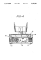
- FIG. 6 is a side view of some of the internal mounting jacks of the system unit and on a portion of which the cover is removed to show the positioning of the mounting bracket with respect to the system unit;
- FIG. 6a is a side view of the opposite side of the system unit
- FIG. 7 is a perspective view of the lower wall mounting bracket of the system unit, which may be attached to the system unit, in either wall or table mounting capabilities.
- the care management workstation unit 10 is comprised of three basic elements.
- This workstation 10 is ideally adapted for use at a nurses' station, in the hospital halls, or at a patient's bedside.
- a cathode ray tube or CRT 20 coupled to a mounting bracket 30 and a system unit 40, which may include a personal computer.
- FIGS. 2a, 3a and 5 which contrast older systems much less compact systems and which created much clutter and many of the dysfunctional capabilities specifically avoided by this system.
- This system provides for a functional, compact and useful system enhancement and therefore allows for increased advancement for the bedside data management system art. Now, each of the elements of the present system 10 will be examined in order.
- the CRT 20 is either a monochrome or color CRT ranging in size from 9 inches to 14 inches. Importantly, the CRT 20 is smaller in depth than typical CRT's used in care management workstation units, measuring only inches in depth. Furthermore, CRT 20 is configured to be rotatable through many degrees, approximately 90 or more degrees. In this way, the user is capable of placing the CRT 20 at eye level, regardless of whether eye level is for standing or sitting purposes or for varying height of the user. Also the CRT 20 is integrated into the system. That is, CRT 20 is attached in some way to the system 10, and is not a separate unit, which is a problem encountered in using other bedside data management systems.
- the CRT 20 is spring mounted on a mounting bracket 30.
- This spring mounting is provided by a torsion spring 35 placed within swivel 37 and is formed into a slip-clutch type mount.
- Torsion spring 35 provides resistance against the weight of CRT 20 where it is connected to the swivel 37. In this way, spring 35 is able to withstand shifts in position of the center of gravity of CRT 20.
- bracket 30 to hold the weight of the CRT unit 20 in virtually any position.
- bracket 30 and torsion spring 35 adequately hold CRT 20 in place. In this way, the CRT 20 now becomes much more ergonomically functional within the system 10.
- the mounting bracket 30 is another important feature of this system.
- This mounting bracket 30, as can be seen in FIGS. 2 and 3, is capable of being placed flush against a wall. Simultaneously, this mounting bracket 30 is capable of maintaining CRT 20 without rotating CRT 20.
- the mounting bracket 30 may contain, under cover 33, a plurality of internal chambers or cable accepting channels 32 which are capable of guiding the wires 22 from the CRT unit 20 into the system unit 40. Cover 33 is retained by screws 34.
- wires 22 may be inserted in a split-block, not shown, which similarly provides a water tight seal in system unit 40.
- the mounting bracket 30 has internally placed screws 38 which hold the mounting bracket 30 against the system unit 40, so that system unit 40 and CRT 20 form an integral unit.
- Mounting bracket 30 is placed within the system unit 40 in a bayonet type mount 42 which makes the mounting bracket 30 much more secure. Furthermore, the rigidity in mounting the mounting bracket 30 causes additional security in the mounting of the CRT. Additionally, one of the useful functions of this mounting bracket 30 is that its rigidity and integrality to the system 10 through its bayonet mount 42, which makes the mounting bracket 30 and the CRT unit 20 integrally replaceable. Yet, because the CRT unit 20 and mounting bracket 30 are attached to the system unit 40 via the screws 38 placed under system unit cover 48, this prevents theft of either unit separately. Advantageously this arrangement also prevents accidents, because CRT 20 cannot be pushed off the top of system unit 40, due to the rigid attachment between these units.
- the mounting bracket 30 is configured to have a slightly upward angle of mounting away from the system unit 40, this allows rotation of the CRT 20 in a front projection so that compactness is maximized. That is, the CRT 20 does not rotate so that its front face is placed in a horizontal plane set apart from the wall on which is mounted the system unit 40 on bracket 30.
- This front projection is roughly 11.5", and no more than 13 inches which is easily smaller than current units, and allows the system to be placed in a corridor or within a care management workstation, without the worry of clumsiness or inhibition of ability to work.
- a position 58 on the mounting bracket 30 for placing of a light pen 55 there is provided a position 58 on the mounting bracket 30 for placing of a light pen 55.
- a mouse 60 as further seen in FIG. 1, or other computer affiliated peripherals like a track ball may be mounted on the mounting bracket without compromising the performance of this system.
- a touch screen can be fitted to CRT 20 without change of the system.
- system unit 40 of this invention is quite compact and yet highly functional. Contained within system unit 40 is a typical large memory computer which has all the usual computer capabilities and interfaces, and yet is also a computer which is able to be maintained in a very limited space environment. The depth of the computer is compact, only 11.5", and this allows it to be placed in virtually any situation for mounting.
- the mount 30 is capable of being placed flush against the wall.
- system 40 may be mounted flush on a table, a function that is quite unique to the bedside data management industry. If the table itself has a computer compatible cutout, cables may be mounted through the bottom of the unit 40 and into the table.
- This integral keyboard 50 is formed as a rack item on system 40. So, while the keyboard 50 can be scrolled in or out, depending on need of use, the tabletop 44 of the system 40 remains clear, and is able to accommodate any number of computer compatible devices. For instance, as shown in FIG. there is mounted a computer mouse 60. Because the cover 48 of system 40 is watertight, the user can use top 44 of the system unit as an actual table and place pads, clipboards, and pens and the like, as well as casually place a cup of coffee or soda on top 44 without worry of spilling into the system unit 40, and allowing both hands of the user to be free for system use and/or patient use.
- the system unit 40 is mounted with space between it and CRT 20, and with the CRT 20 centrally located.
- the tabletop 44 of the system unit 40 becomes quite functional to either the left-handed or right-handed user.
- the spacing between the mounting bracket 30 and system unit 40 allows for work space upon the entire system unit tabletop.
- the integral internal ports 49 for cables and for mount 30 of CRT 20 allow for the sealing, and the prevention of leakage within the cabinet of the system unit 40. Also, this decreases the bulkiness of the entire unit 40. As well, it also provides for an entirely integral system.
- the mounting bracket 30, because it is internally mounted within the system unit 40, provides strain relief and torque resistance to the system 10, and is therefore capable of meeting all user and industrial functions.
- an internally mounted power supply 70 and isolation transformer 90 is also provided.
- This internally mounted transformer 90 which is a modification of a commercially available design, allows for the use of an industry standard power supply system unit. In this way, the entire system unit 40 is mobile and fully integral, and is able to be compactly transported without need to worry about the need for a separate isolation transformer.
- system unit 40 is provided with connector parts 46a, 46b, 46c on cover 48, which allow connection to a patient of the internally installed monitoring electronics or other monitoring units such as additional systems emplaced in the lower mounting bracket 100 of FIG. 7. Also, importantly, it is seen that these connector parts 46a, b, c are integral to system unit 40, which creates a powerful computing source. In both these ways, system unit 40 is substantially different from a typical computer, which has no such monitoring capacity.
- FIG. 6a there are provided internal computer peripheral connectors, 47a, 47b, 47c. These connectors are located within the unit 40, and eliminate the danger of tampering with the computer. As well, they improve the system aesthetics.
- a lower mounting bracket 100 which is compatible with the planar lower surface which forms the underside 47 of the system unit 40.
- system unit 40 can be fit into the holes 103 provided in the top 102 of the lower mounting bracket 100, which also fits flush on side 104 against a wall.
- a modular vital sign monitoring unit can be placed within this lower mounting bracket 100 so that this system 10 can be enhanced to provide other vital signs monitoring functions in addition to, or in place of the monitoring electronics optionally included in the system.
- tabletop 44 still remains available on system unit 40, and modularity is maintained.
- the feet 43 (FIG. 4) of the system unit 40 fit within the lower mounting bracket 100, there is no need to remove any of the mounts during placement of this lower mounting bracket 100.
- an integral, modular and compact care management workstation unit 10 is provided, which has many ergonomic enhancements previously unavailable. Furthermore, the system is powerful enough to handle all bedside data management functions without compromising this utility, including optional electronic patient monitoring, as well as the more traditional computing functions.
Abstract
Description
Claims (44)
Priority Applications (5)
| Application Number | Priority Date | Filing Date | Title |
|---|---|---|---|
| US07/782,020 US5187641A (en) | 1991-10-24 | 1991-10-24 | Patient monitoring unit and care station |
| CA002081194A CA2081194A1 (en) | 1991-10-24 | 1992-10-22 | Patient monitoring unit and care station |
| ES92309746T ES2128341T3 (en) | 1991-10-24 | 1992-10-23 | SURVEILLANCE UNIT AND PATIENT CONTROL POST. |
| EP92309746A EP0542442B1 (en) | 1991-10-24 | 1992-10-23 | Patient monitoring unit and care station |
| JP4307861A JPH0622913A (en) | 1991-10-24 | 1992-10-23 | Patient monitoring apparatus and nursing terminal |
Applications Claiming Priority (1)
| Application Number | Priority Date | Filing Date | Title |
|---|---|---|---|
| US07/782,020 US5187641A (en) | 1991-10-24 | 1991-10-24 | Patient monitoring unit and care station |
Publications (1)
| Publication Number | Publication Date |
|---|---|
| US5187641A true US5187641A (en) | 1993-02-16 |
Family
ID=25124694
Family Applications (1)
| Application Number | Title | Priority Date | Filing Date |
|---|---|---|---|
| US07/782,020 Expired - Fee Related US5187641A (en) | 1991-10-24 | 1991-10-24 | Patient monitoring unit and care station |
Country Status (5)
| Country | Link |
|---|---|
| US (1) | US5187641A (en) |
| EP (1) | EP0542442B1 (en) |
| JP (1) | JPH0622913A (en) |
| CA (1) | CA2081194A1 (en) |
| ES (1) | ES2128341T3 (en) |
Cited By (42)
| Publication number | Priority date | Publication date | Assignee | Title |
|---|---|---|---|---|
| US5388032A (en) * | 1993-05-04 | 1995-02-07 | Ibus Technologies, Inc. | Computer equipment monitor and discriminator |
| US5544005A (en) * | 1993-07-07 | 1996-08-06 | International Business Machines Corporation | Keyboard storage apparatus having a cable end moved by movement of a keyboard housing section |
| US5673169A (en) * | 1995-10-03 | 1997-09-30 | Sony Corporation | Wall mounted personal communications routing system |
| US5788851A (en) * | 1995-02-13 | 1998-08-04 | Aksys, Ltd. | User interface and method for control of medical instruments, such as dialysis machines |
| US5812368A (en) * | 1997-06-04 | 1998-09-22 | Kuo Feng Corporation | Monitor viewing angle adjusting assembly having monitor mounted on two supporting arm assemblies via turning limit assemblies |
| US5838536A (en) * | 1995-11-30 | 1998-11-17 | Fujitsu Limited | Display device having tilt mechanism for adjustment with respect to operator device |
| DE19834846A1 (en) * | 1998-08-01 | 2000-02-03 | Bruno Gruber | Personal computer monitor console has space defined between cover plate, base plate and rear wall for storage of computer keyboard |
| DE19952400A1 (en) * | 1999-10-29 | 2001-05-10 | Wincor Nixdorf Gmbh & Co Kg | Computer workstation for table and wall mounting |
| US6335859B1 (en) * | 2000-03-13 | 2002-01-01 | Compal Electronics, Inc. | Optical disk drive assembly having a control panel mounted movably thereon |
| US6344968B2 (en) * | 1998-06-24 | 2002-02-05 | Samsung Electronics Co., Ltd. | Controller for electronic goods |
| US6480372B1 (en) * | 2000-04-24 | 2002-11-12 | Microsoft Corporation | Computer with a hidden keyboard |
| US20030052787A1 (en) * | 2001-08-03 | 2003-03-20 | Zerhusen Robert Mark | Patient point-of-care computer system |
| US20040186357A1 (en) * | 2002-08-20 | 2004-09-23 | Welch Allyn, Inc. | Diagnostic instrument workstation |
| US20050113734A1 (en) * | 1997-02-14 | 2005-05-26 | Brugger James M. | Network-based extracorporeal blood treatment information system |
| US20050284341A1 (en) * | 2004-06-23 | 2005-12-29 | Klassy Aaron C | Modular desk system |
| US20050288571A1 (en) * | 2002-08-20 | 2005-12-29 | Welch Allyn, Inc. | Mobile medical workstation |
| US20060132006A1 (en) * | 2004-12-22 | 2006-06-22 | Robert Schluter | Rack cabinet |
| US20060155196A1 (en) * | 2005-01-10 | 2006-07-13 | Maynard Ramsey | Integrated manual mechanical and electronic sphygmomanometer within a single enclosure |
| US20080035811A1 (en) * | 2006-08-14 | 2008-02-14 | Samsung Electronics Co., Ltd. | Apparatus for supporting display device |
| US20080149551A1 (en) * | 1999-11-29 | 2008-06-26 | Nxstage Medical, Inc. | Blood treatment apparatus |
| US20080281168A1 (en) * | 2005-01-13 | 2008-11-13 | Welch Allyn, Inc. | Vital Signs Monitor |
| US20090012453A1 (en) * | 2007-07-05 | 2009-01-08 | Baxter International Inc. | Mobile dialysis system having supply container detection |
| US20100010320A1 (en) * | 2008-07-07 | 2010-01-14 | Perkins David G | Mobile medical workstation and a temporarily associating mobile computing device |
| US20110279958A1 (en) * | 1998-09-18 | 2011-11-17 | Intermetro Industries Corporation | Mobile Computer Workstation |
| US8257299B2 (en) | 2007-07-05 | 2012-09-04 | Baxter International | Dialysis methods and systems having autoconnection and autoidentification |
| USD684982S1 (en) | 2010-08-11 | 2013-06-25 | Colebrook Bosson Saunders (Products) Limited | Display support with indicator window |
| US8618918B2 (en) | 2010-04-09 | 2013-12-31 | Hill-Rom Services, Inc. | Patient support, communication, and computing apparatus including movement of the support and connection to the hospital network |
| US8667908B2 (en) | 2010-06-02 | 2014-03-11 | Steelcase Inc. | Frame type table assemblies |
| US8689705B2 (en) | 2010-06-02 | 2014-04-08 | Steelcase, Inc. | Reconfigurable table assemblies |
| US20140268513A1 (en) * | 2013-03-15 | 2014-09-18 | Toshiba Global Commerce Solutions Holdings Corporation | Display screen assembly having a selectively engageable mount assembly |
| US9074721B2 (en) | 2010-06-09 | 2015-07-07 | Alex Lau | Support system |
| US9185974B2 (en) | 2010-06-02 | 2015-11-17 | Steelcase Inc. | Frame type workstation configurations |
| US9210999B2 (en) | 2010-06-02 | 2015-12-15 | Steelcase Inc. | Frame type table assemblies |
| US9242664B2 (en) | 2003-02-24 | 2016-01-26 | Capsa Solutions, Llc | Medical cart, medication module, height adjustment mechanism, and method of medication transport |
| US9316346B2 (en) | 2010-06-09 | 2016-04-19 | Colebrook Bosson Saunders (Products) Limited | Support system |
| US9539155B2 (en) | 2012-10-26 | 2017-01-10 | Hill-Rom Services, Inc. | Control system for patient support apparatus |
| US9586003B2 (en) | 2007-07-05 | 2017-03-07 | Baxter International Inc. | Medical fluid machine with supply autoconnection |
| US10039374B2 (en) | 2016-05-13 | 2018-08-07 | Steelcase Inc. | Multi-tiered workstation assembly |
| US20180226050A1 (en) * | 2015-09-16 | 2018-08-09 | Shenzhen Mindray Bio-Medical Electronics Co., Ltd. | Monitor, display device thereof, and monitoring system |
| US10293091B2 (en) | 2007-07-05 | 2019-05-21 | Baxter International Inc. | Dialysis system having an autoconnection mechanism |
| US10474808B2 (en) | 2013-03-29 | 2019-11-12 | Hill-Rom Services, Inc. | Hospital bed compatibility with third party application software |
| US10517392B2 (en) | 2016-05-13 | 2019-12-31 | Steelcase Inc. | Multi-tiered workstation assembly |
Citations (22)
| Publication number | Priority date | Publication date | Assignee | Title |
|---|---|---|---|---|
| US3844395A (en) * | 1973-09-12 | 1974-10-29 | Extel Corp | Text display control for data printer |
| GB2069197A (en) * | 1980-02-06 | 1981-08-19 | Honeywell Inc | Computer control console |
| US4478382A (en) * | 1981-08-21 | 1984-10-23 | Plessey Overseas Limited | Pivotal mounting system |
| US4496200A (en) * | 1982-09-30 | 1985-01-29 | Teletype Corporation | Desk top keyboard display terminal with an articulated keyboard |
| WO1985001648A1 (en) * | 1983-10-11 | 1985-04-25 | Tektronix, Inc. | Computer terminal stand |
| JPS6084623A (en) * | 1983-10-15 | 1985-05-14 | Ricoh Co Ltd | Information processor |
| US4516751A (en) * | 1982-09-17 | 1985-05-14 | Charles Westbrook | Wall bracket system |
| US4560132A (en) * | 1984-10-11 | 1985-12-24 | Wilder Leslie N | Stand for display devices |
| US4576578A (en) * | 1983-03-31 | 1986-03-18 | Bell & Howell Company | Interactive training apparatus |
| US4624510A (en) * | 1982-01-18 | 1986-11-25 | Jedziniak Francis J | Storage assembly for data processing device |
| US4638969A (en) * | 1984-12-24 | 1987-01-27 | Milliken Research Corporation | Video display arrangement |
| US4696522A (en) * | 1986-05-09 | 1987-09-29 | Devoke Co. | Cabinet for microcomputer components |
| US4708312A (en) * | 1985-10-23 | 1987-11-24 | Ncr Corporation | Extensible height-adjustable swivel arm for supporting a display or the like |
| US4709972A (en) * | 1986-08-27 | 1987-12-01 | Eastman Kodak Company | Keyboard cabinet with sliding tray |
| US4735467A (en) * | 1986-05-23 | 1988-04-05 | Westinghouse Electric Corp. | Stow away flat screen mechanism |
| EP0280096A1 (en) * | 1987-02-09 | 1988-08-31 | Tandberg Data A/S | Supporting arrangement for a video display unit |
| US4861121A (en) * | 1987-10-01 | 1989-08-29 | Lam-Wood Products Inc. | Space efficient cabinet for housing a computer work station |
| US4964606A (en) * | 1989-10-26 | 1990-10-23 | Ncr Corporation | Overhead mount for a CRT |
| US5007608A (en) * | 1989-08-28 | 1991-04-16 | Kim Manufacturing Company | Television wall bracket |
| US5020449A (en) * | 1988-08-04 | 1991-06-04 | Forte Jerry K | Shelved computer stand |
| US5041770A (en) * | 1989-11-16 | 1991-08-20 | Seiler Michael A | Apparatus for adjusting a computer work station to individual needs |
| US5071204A (en) * | 1985-04-05 | 1991-12-10 | Engineered Data Products, Inc. | Desk-type computer work station |
Family Cites Families (3)
| Publication number | Priority date | Publication date | Assignee | Title |
|---|---|---|---|---|
| US4669694A (en) * | 1985-12-23 | 1987-06-02 | American Telephone And Telegraph Company, At&T Bell Laboratories | Tilt adjusting mechanism |
| EP0321137A3 (en) * | 1987-12-18 | 1989-12-20 | HILL-ROM COMPANY, INC. (an Indiana corporation) | Computer cart |
| DE3914499A1 (en) * | 1989-05-02 | 1990-11-08 | Bza Biometrisches Zentrum Aach | METHOD FOR ENTERING INPUT DATA AND METHOD FOR ASSIGNING NEW PATIENT DATA TO EXISTING DATA AND INPUT SYSTEM |
-
1991
- 1991-10-24 US US07/782,020 patent/US5187641A/en not_active Expired - Fee Related
-
1992
- 1992-10-22 CA CA002081194A patent/CA2081194A1/en not_active Abandoned
- 1992-10-23 ES ES92309746T patent/ES2128341T3/en not_active Expired - Lifetime
- 1992-10-23 EP EP92309746A patent/EP0542442B1/en not_active Expired - Lifetime
- 1992-10-23 JP JP4307861A patent/JPH0622913A/en active Pending
Patent Citations (22)
| Publication number | Priority date | Publication date | Assignee | Title |
|---|---|---|---|---|
| US3844395A (en) * | 1973-09-12 | 1974-10-29 | Extel Corp | Text display control for data printer |
| GB2069197A (en) * | 1980-02-06 | 1981-08-19 | Honeywell Inc | Computer control console |
| US4478382A (en) * | 1981-08-21 | 1984-10-23 | Plessey Overseas Limited | Pivotal mounting system |
| US4624510A (en) * | 1982-01-18 | 1986-11-25 | Jedziniak Francis J | Storage assembly for data processing device |
| US4516751A (en) * | 1982-09-17 | 1985-05-14 | Charles Westbrook | Wall bracket system |
| US4496200A (en) * | 1982-09-30 | 1985-01-29 | Teletype Corporation | Desk top keyboard display terminal with an articulated keyboard |
| US4576578A (en) * | 1983-03-31 | 1986-03-18 | Bell & Howell Company | Interactive training apparatus |
| WO1985001648A1 (en) * | 1983-10-11 | 1985-04-25 | Tektronix, Inc. | Computer terminal stand |
| JPS6084623A (en) * | 1983-10-15 | 1985-05-14 | Ricoh Co Ltd | Information processor |
| US4560132A (en) * | 1984-10-11 | 1985-12-24 | Wilder Leslie N | Stand for display devices |
| US4638969A (en) * | 1984-12-24 | 1987-01-27 | Milliken Research Corporation | Video display arrangement |
| US5071204A (en) * | 1985-04-05 | 1991-12-10 | Engineered Data Products, Inc. | Desk-type computer work station |
| US4708312A (en) * | 1985-10-23 | 1987-11-24 | Ncr Corporation | Extensible height-adjustable swivel arm for supporting a display or the like |
| US4696522A (en) * | 1986-05-09 | 1987-09-29 | Devoke Co. | Cabinet for microcomputer components |
| US4735467A (en) * | 1986-05-23 | 1988-04-05 | Westinghouse Electric Corp. | Stow away flat screen mechanism |
| US4709972A (en) * | 1986-08-27 | 1987-12-01 | Eastman Kodak Company | Keyboard cabinet with sliding tray |
| EP0280096A1 (en) * | 1987-02-09 | 1988-08-31 | Tandberg Data A/S | Supporting arrangement for a video display unit |
| US4861121A (en) * | 1987-10-01 | 1989-08-29 | Lam-Wood Products Inc. | Space efficient cabinet for housing a computer work station |
| US5020449A (en) * | 1988-08-04 | 1991-06-04 | Forte Jerry K | Shelved computer stand |
| US5007608A (en) * | 1989-08-28 | 1991-04-16 | Kim Manufacturing Company | Television wall bracket |
| US4964606A (en) * | 1989-10-26 | 1990-10-23 | Ncr Corporation | Overhead mount for a CRT |
| US5041770A (en) * | 1989-11-16 | 1991-08-20 | Seiler Michael A | Apparatus for adjusting a computer work station to individual needs |
Cited By (81)
| Publication number | Priority date | Publication date | Assignee | Title |
|---|---|---|---|---|
| US5388032A (en) * | 1993-05-04 | 1995-02-07 | Ibus Technologies, Inc. | Computer equipment monitor and discriminator |
| US5544005A (en) * | 1993-07-07 | 1996-08-06 | International Business Machines Corporation | Keyboard storage apparatus having a cable end moved by movement of a keyboard housing section |
| US5788851A (en) * | 1995-02-13 | 1998-08-04 | Aksys, Ltd. | User interface and method for control of medical instruments, such as dialysis machines |
| US6146523A (en) * | 1995-02-13 | 2000-11-14 | Aksys, Ltd. | User interface and method for control of medical instruments, such as dialysis machines |
| US5673169A (en) * | 1995-10-03 | 1997-09-30 | Sony Corporation | Wall mounted personal communications routing system |
| US5838536A (en) * | 1995-11-30 | 1998-11-17 | Fujitsu Limited | Display device having tilt mechanism for adjustment with respect to operator device |
| US20050113734A1 (en) * | 1997-02-14 | 2005-05-26 | Brugger James M. | Network-based extracorporeal blood treatment information system |
| WO1998035747A1 (en) * | 1997-02-14 | 1998-08-20 | Aksys, Ltd. | Dialysis machines with touch screen user interface |
| US7776001B2 (en) | 1997-02-14 | 2010-08-17 | Nxstage Medical Inc. | Registration of fluid circuit components in a blood treatment device |
| US5812368A (en) * | 1997-06-04 | 1998-09-22 | Kuo Feng Corporation | Monitor viewing angle adjusting assembly having monitor mounted on two supporting arm assemblies via turning limit assemblies |
| US6344968B2 (en) * | 1998-06-24 | 2002-02-05 | Samsung Electronics Co., Ltd. | Controller for electronic goods |
| DE19834846A1 (en) * | 1998-08-01 | 2000-02-03 | Bruno Gruber | Personal computer monitor console has space defined between cover plate, base plate and rear wall for storage of computer keyboard |
| US9389643B1 (en) | 1998-09-18 | 2016-07-12 | Intermetro Industries Corporation | Mobile computer workstation |
| US8526176B2 (en) * | 1998-09-18 | 2013-09-03 | Intermetro Industries Corporation | Mobile computer workstation |
| US20110279958A1 (en) * | 1998-09-18 | 2011-11-17 | Intermetro Industries Corporation | Mobile Computer Workstation |
| DE19952400A1 (en) * | 1999-10-29 | 2001-05-10 | Wincor Nixdorf Gmbh & Co Kg | Computer workstation for table and wall mounting |
| US7780619B2 (en) | 1999-11-29 | 2010-08-24 | Nxstage Medical, Inc. | Blood treatment apparatus |
| US20080149551A1 (en) * | 1999-11-29 | 2008-06-26 | Nxstage Medical, Inc. | Blood treatment apparatus |
| US6335859B1 (en) * | 2000-03-13 | 2002-01-01 | Compal Electronics, Inc. | Optical disk drive assembly having a control panel mounted movably thereon |
| US6480372B1 (en) * | 2000-04-24 | 2002-11-12 | Microsoft Corporation | Computer with a hidden keyboard |
| US8368545B2 (en) | 2001-08-03 | 2013-02-05 | Hill-Rom Services, Inc. | Hospital bed computer system with pharmacy interaction |
| US20110166891A1 (en) * | 2001-08-03 | 2011-07-07 | Robert Mark Zerhusen | Hospital bed computer system with pharmacy interaction |
| US8674839B2 (en) | 2001-08-03 | 2014-03-18 | Hill-Rom Services, Inc. | Hospital bed computer system for control of patient room environment |
| US7154397B2 (en) | 2001-08-03 | 2006-12-26 | Hill Rom Services, Inc. | Patient point-of-care computer system |
| US20030052787A1 (en) * | 2001-08-03 | 2003-03-20 | Zerhusen Robert Mark | Patient point-of-care computer system |
| US10381116B2 (en) | 2001-08-03 | 2019-08-13 | Hill-Rom Services, Inc. | Hospital bed computer system |
| US8334779B2 (en) | 2001-08-03 | 2012-12-18 | Hill-Rom Services, Inc. | Touch screen control of a hospital bed |
| US20070120689A1 (en) * | 2001-08-03 | 2007-05-31 | Zerhusen Robert M | Patient point-of-care computer system |
| US7679520B2 (en) | 2001-08-03 | 2010-03-16 | Hill-Rom Services, Inc. | Patient point-of-care computer system |
| US20100154124A1 (en) * | 2001-08-03 | 2010-06-24 | Robert Mark Zerhusen | Hospital bed computer system |
| US10176297B2 (en) | 2001-08-03 | 2019-01-08 | Hill-Rom Services, Inc. | Hospital bed computer system having EMR charting capability |
| US7911349B2 (en) | 2001-08-03 | 2011-03-22 | Hill-Rom Services, Inc. | Hospital bed computer system |
| US8292807B2 (en) | 2002-08-20 | 2012-10-23 | Welch Allyn, Inc. | Mobile medical workstation |
| US20090221880A1 (en) * | 2002-08-20 | 2009-09-03 | Welch Allyn, Inc. | Diagnostic instrument workstation |
| US20050288571A1 (en) * | 2002-08-20 | 2005-12-29 | Welch Allyn, Inc. | Mobile medical workstation |
| US10010287B2 (en) | 2002-08-20 | 2018-07-03 | Welch Allyn, Inc. | Mobile medical workstation |
| US20040186357A1 (en) * | 2002-08-20 | 2004-09-23 | Welch Allyn, Inc. | Diagnostic instrument workstation |
| US9242664B2 (en) | 2003-02-24 | 2016-01-26 | Capsa Solutions, Llc | Medical cart, medication module, height adjustment mechanism, and method of medication transport |
| US20050284341A1 (en) * | 2004-06-23 | 2005-12-29 | Klassy Aaron C | Modular desk system |
| US20060132006A1 (en) * | 2004-12-22 | 2006-06-22 | Robert Schluter | Rack cabinet |
| US20060155196A1 (en) * | 2005-01-10 | 2006-07-13 | Maynard Ramsey | Integrated manual mechanical and electronic sphygmomanometer within a single enclosure |
| US8016765B2 (en) | 2005-01-10 | 2011-09-13 | Ramsey Medical Inc. | Integrated manual mechanical and electronic sphygmomanometer within a single enclosure |
| US8932217B2 (en) | 2005-01-13 | 2015-01-13 | Welch Allyn, Inc. | Vital signs monitor |
| US10165950B2 (en) | 2005-01-13 | 2019-01-01 | Welch Allyn, Inc. | Vital signs monitor |
| US20080281168A1 (en) * | 2005-01-13 | 2008-11-13 | Welch Allyn, Inc. | Vital Signs Monitor |
| US20080035811A1 (en) * | 2006-08-14 | 2008-02-14 | Samsung Electronics Co., Ltd. | Apparatus for supporting display device |
| US10293091B2 (en) | 2007-07-05 | 2019-05-21 | Baxter International Inc. | Dialysis system having an autoconnection mechanism |
| US11730868B2 (en) | 2007-07-05 | 2023-08-22 | Baxter International Inc. | Dialysis system having an autoconnection mechanism |
| US20090012453A1 (en) * | 2007-07-05 | 2009-01-08 | Baxter International Inc. | Mobile dialysis system having supply container detection |
| US8105266B2 (en) | 2007-07-05 | 2012-01-31 | Baxter International Inc. | Mobile dialysis system having supply container detection |
| US8257299B2 (en) | 2007-07-05 | 2012-09-04 | Baxter International | Dialysis methods and systems having autoconnection and autoidentification |
| US9586003B2 (en) | 2007-07-05 | 2017-03-07 | Baxter International Inc. | Medical fluid machine with supply autoconnection |
| US20100010320A1 (en) * | 2008-07-07 | 2010-01-14 | Perkins David G | Mobile medical workstation and a temporarily associating mobile computing device |
| US8618918B2 (en) | 2010-04-09 | 2013-12-31 | Hill-Rom Services, Inc. | Patient support, communication, and computing apparatus including movement of the support and connection to the hospital network |
| US9253259B2 (en) | 2010-04-09 | 2016-02-02 | Hill-Rom Services, Inc. | Patient support, communication, and computing apparatus |
| US10681980B2 (en) | 2010-06-02 | 2020-06-16 | Steelcase Inc. | Frame type workstation configurations |
| US11930926B2 (en) | 2010-06-02 | 2024-03-19 | Steelcase Inc. | Frame type workstation configurations |
| US11317716B2 (en) | 2010-06-02 | 2022-05-03 | Steelcase Inc. | Frame type workstation configurations |
| US8667908B2 (en) | 2010-06-02 | 2014-03-11 | Steelcase Inc. | Frame type table assemblies |
| US8689705B2 (en) | 2010-06-02 | 2014-04-08 | Steelcase, Inc. | Reconfigurable table assemblies |
| US11944194B2 (en) | 2010-06-02 | 2024-04-02 | Steelcase Inc. | Frame type workstation configurations |
| US9210999B2 (en) | 2010-06-02 | 2015-12-15 | Steelcase Inc. | Frame type table assemblies |
| US9185974B2 (en) | 2010-06-02 | 2015-11-17 | Steelcase Inc. | Frame type workstation configurations |
| US11882934B2 (en) | 2010-06-02 | 2024-01-30 | Steelcase Inc. | Frame type workstation configurations |
| US9572269B2 (en) | 2010-06-09 | 2017-02-14 | Colebrook Bosson Saunders (Products) Limited | Support system |
| US9316346B2 (en) | 2010-06-09 | 2016-04-19 | Colebrook Bosson Saunders (Products) Limited | Support system |
| US9074721B2 (en) | 2010-06-09 | 2015-07-07 | Alex Lau | Support system |
| USD684982S1 (en) | 2010-08-11 | 2013-06-25 | Colebrook Bosson Saunders (Products) Limited | Display support with indicator window |
| USD1005984S1 (en) | 2010-08-11 | 2023-11-28 | Colebrook Bosson & Saunders (Products) Limited | Indicator window for a display support |
| US10512573B2 (en) | 2012-10-26 | 2019-12-24 | Hill-Rom Services, Inc. | Control system for patient support apparatus |
| US9539155B2 (en) | 2012-10-26 | 2017-01-10 | Hill-Rom Services, Inc. | Control system for patient support apparatus |
| US9164537B2 (en) * | 2013-03-15 | 2015-10-20 | Toshiba Global Commerce Solutions Holding Corporation | Display screen assembly having a selectively engageable mount assembly |
| US20140268513A1 (en) * | 2013-03-15 | 2014-09-18 | Toshiba Global Commerce Solutions Holdings Corporation | Display screen assembly having a selectively engageable mount assembly |
| US10474808B2 (en) | 2013-03-29 | 2019-11-12 | Hill-Rom Services, Inc. | Hospital bed compatibility with third party application software |
| US11869649B2 (en) | 2013-03-29 | 2024-01-09 | Hill-Rom Services, Inc. | Universal interface operable with multiple patient support apparatuses |
| US20180226050A1 (en) * | 2015-09-16 | 2018-08-09 | Shenzhen Mindray Bio-Medical Electronics Co., Ltd. | Monitor, display device thereof, and monitoring system |
| US11348551B2 (en) | 2015-09-16 | 2022-05-31 | Shenzhen Mindray Bio-Medical Electronics Co., Ltd. | Monitor, display device thereof, and monitoring system |
| US10832629B2 (en) * | 2015-09-16 | 2020-11-10 | Shenzhen Mindray Bio-Medical Electronics Co., Ltd. | Monitor, display device thereof, and monitoring system |
| US10621946B2 (en) * | 2015-09-16 | 2020-04-14 | Shenzhen Mindray Bio-Medical Electronics Co., Ltd. | Monitor, display device thereof, and monitoring system |
| US10517392B2 (en) | 2016-05-13 | 2019-12-31 | Steelcase Inc. | Multi-tiered workstation assembly |
| US10039374B2 (en) | 2016-05-13 | 2018-08-07 | Steelcase Inc. | Multi-tiered workstation assembly |
Also Published As
| Publication number | Publication date |
|---|---|
| ES2128341T3 (en) | 1999-05-16 |
| CA2081194A1 (en) | 1993-04-25 |
| EP0542442A1 (en) | 1993-05-19 |
| EP0542442B1 (en) | 1999-01-13 |
| JPH0622913A (en) | 1994-02-01 |
Similar Documents
| Publication | Publication Date | Title |
|---|---|---|
| US5187641A (en) | Patient monitoring unit and care station | |
| JP3432798B2 (en) | Integrated docking tray assembly | |
| US7679902B2 (en) | Vertical docking station | |
| TW444155B (en) | Detachable flat panel computer display and support | |
| US5899421A (en) | Stand for a portable computer | |
| KR200281313Y1 (en) | Computer display | |
| US4814759A (en) | Flat panel display monitor apparatus | |
| US7274564B2 (en) | Locking cradle for tablet computers | |
| US6081420A (en) | LCD display apparatus | |
| EP2183655B1 (en) | Dual screen presentation notebook computer | |
| US5815735A (en) | Portable computer with removable display screen using removably mateable connectors to form the sole supporting interconnection between the computer base portion and display screen structure | |
| TW393597B (en) | Portable computer having articulated display | |
| US6867961B2 (en) | Portable computer | |
| US5566098A (en) | Rotatable pen-based computer with automatically reorienting display | |
| US20140263884A1 (en) | Swivel Mount | |
| EP1230586B1 (en) | Horizontal three screen lcd display system | |
| JP2002297261A (en) | Multi-attitude docking station for computer | |
| US20240081009A1 (en) | Low profile computer support | |
| US20020027533A1 (en) | Display device and information processing apparatus | |
| US5944292A (en) | Ergonomical trackball mount | |
| KR20070069663A (en) | Multi monitor apparatus | |
| AU776703B2 (en) | Lectern | |
| US20220253101A1 (en) | Portable Triple Mount | |
| JP2005316867A (en) | Information processor | |
| GB2321982A (en) | Positioning notebook computer screen to facilitate use with external keyboard |
Legal Events
| Date | Code | Title | Description |
|---|---|---|---|
| AS | Assignment |
Owner name: CRITIKON, INC., Free format text: ASSIGNMENT OF ASSIGNORS INTEREST.;ASSIGNORS:MUSKATELLO, JAMES M.;PARMET, DARRYL;LYSY, GEORGE C.;AND OTHERS;REEL/FRAME:005954/0433 Effective date: 19911209 |
|
| FEPP | Fee payment procedure |
Free format text: PAYOR NUMBER ASSIGNED (ORIGINAL EVENT CODE: ASPN); ENTITY STATUS OF PATENT OWNER: LARGE ENTITY |
|
| FPAY | Fee payment |
Year of fee payment: 4 |
|
| AS | Assignment |
Owner name: JOHNSON & JOHNSON MEDICAL INC., NEW JERSEY Free format text: MERGER AND CHANGE OF NAME;ASSIGNOR:CRITIKON, INC.;REEL/FRAME:008535/0586 Effective date: 19950102 |
|
| AS | Assignment |
Owner name: CRITIKON COMPANY, L.L.C., FLORIDA Free format text: ASSIGNMENT OF ASSIGNORS INTEREST;ASSIGNOR:ETHICON, INC.;REEL/FRAME:009703/0280 Effective date: 19981022 |
|
| AS | Assignment |
Owner name: STATE BOARD OF ADMINISTRATION OF FLORIDA, THE, NEW Free format text: SENIOR SECURITY AGREEMENT FOR PATENT;ASSIGNOR:CRITIKON COMPANY, L.L.C.;REEL/FRAME:009648/0508 Effective date: 19981103 |
|
| AS | Assignment |
Owner name: STATE BOARD OF ADMINISTRATION OF FLORIDA, THE, NEW Free format text: SUBORDINATED SECURITY AGREEMENT FOR PATENTS;ASSIGNOR:CRITIKON COMPANY, L.L.C.;REEL/FRAME:009662/0013 Effective date: 19981103 |
|
| REMI | Maintenance fee reminder mailed | ||
| LAPS | Lapse for failure to pay maintenance fees | ||
| FP | Lapsed due to failure to pay maintenance fee |
Effective date: 20010216 |
|
| STCH | Information on status: patent discontinuation |
Free format text: PATENT EXPIRED DUE TO NONPAYMENT OF MAINTENANCE FEES UNDER 37 CFR 1.362 |