US5147406A - Femoral component for a knee joint prosthesis having a modular cam and stem - Google Patents
Femoral component for a knee joint prosthesis having a modular cam and stem Download PDFInfo
- Publication number
- US5147406A US5147406A US07/690,191 US69019191A US5147406A US 5147406 A US5147406 A US 5147406A US 69019191 A US69019191 A US 69019191A US 5147406 A US5147406 A US 5147406A
- Authority
- US
- United States
- Prior art keywords
- cam
- stem
- femoral component
- stem base
- side walls
- Prior art date
- Legal status (The legal status is an assumption and is not a legal conclusion. Google has not performed a legal analysis and makes no representation as to the accuracy of the status listed.)
- Expired - Lifetime
Links
Images


Classifications
-
- A—HUMAN NECESSITIES
- A61—MEDICAL OR VETERINARY SCIENCE; HYGIENE
- A61F—FILTERS IMPLANTABLE INTO BLOOD VESSELS; PROSTHESES; DEVICES PROVIDING PATENCY TO, OR PREVENTING COLLAPSING OF, TUBULAR STRUCTURES OF THE BODY, e.g. STENTS; ORTHOPAEDIC, NURSING OR CONTRACEPTIVE DEVICES; FOMENTATION; TREATMENT OR PROTECTION OF EYES OR EARS; BANDAGES, DRESSINGS OR ABSORBENT PADS; FIRST-AID KITS
- A61F2/00—Filters implantable into blood vessels; Prostheses, i.e. artificial substitutes or replacements for parts of the body; Appliances for connecting them with the body; Devices providing patency to, or preventing collapsing of, tubular structures of the body, e.g. stents
- A61F2/02—Prostheses implantable into the body
- A61F2/30—Joints
- A61F2/38—Joints for elbows or knees
- A61F2/3886—Joints for elbows or knees for stabilising knees against anterior or lateral dislocations
Definitions
- This invention relates to a femoral component of a knee joint prosthesis and has specific relevance to a femoral component having a modular cam for providing posterior tibial subluxation resistance when the posterior cruciate ligament is removed.
- the posterior cruciate ligament When performing a total knee arthroplasty it is beneficial to intraoperatively decide on the viability of the posterior cruciate ligament. If the posterior cruciate ligament is functional then a knee joint prosthesis utilizing the ligament may be used. If, however, the ligament is nonfunctional and is removed, a posterior cruciate ligament substituting prosthetic knee joint may be desired to provide posterior tibial subluxation resistance.
- the '298 patent discloses a modular knee joint prosthesis wherein an augmentation plate may be connected during surgery to the femoral contact surface of a femoral component.
- the plate provides augmentation for the distal end of the femur and includes a triangle stop and transverse post which engages a ramp post on the tibial articulating surface to limit undesirable movement.
- a problem with the '298 patent is that the modular plate component combines the distal augmentation with the triangle stop and there may be instances where posterior subluxation resistance may be desirable without distal augmentation of the femur.
- the femoral component for a knee joint prosthesis of this invention eliminates the problems above by providing a modular cam which may be connected intraoperatively to the femoral component to engage a spine on the tibial articulate surface to provide posterior tibial subluxation without providing distal augmentation of the femur.
- the cam includes a body having an opening therethrough to accommodate a threaded portion of a stem extension and a cam bar extending therefrom.
- the stem extension is turned into an internally threaded stem base on the femoral component to secure the cam body therebetween.
- the cam bar extends in the direction of the posterior condyles and engages the tibial articulating surface to limit movement of the femoral component relative to the articulating surface.
- the stem extension may be formed in a variety of lengths, or shapes.
- the stem extension is secured against rotation relative to the stem by the use of locking threads on the post.
- a through bore may be transverse to the stem of the femoral component and in communication therewith, the transverse bore providing access to a portion of the threads on the stem extension when seated.
- a thread deforming tool engages a portion of the threads through the transverse bore to deform a portion of the threads to an extent that rotation of the stem extension in either direction is prohibited. Rotation of the cam relative to the femoral component is prevented by mutually engaging splines and grooves.
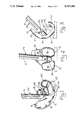
- FIG. 1 is a perspective view of the femoral component, cam, and stem extension of the preferred embodiment with a tibial articulate surface shown in broken lines for illustrative purposes only.
- FIG. 2 is a rear end elevational view of FIG. 1.
- FIG. 3 is a side elevational view FIG. 1.
- FIG. 4 is an exploded view of FIG. 3.
- FIG. 5 is a sectional view of the invention illustrating an alternative method of securing the post extension to the femoral component.
- FIG. 6 is a partial sectional view of FIG. 4.
- FIG. 7 is a perspective view of an alternative embodiment of the cam of the invention.
- FIG. 8 is a sectional view taken along line 8--8 of FIG. 7.
- FIG. 9 is a perspective view of a third alternative embodiment of the cam of the invention.
- FIG. 10 is a sectional view taken along line 10--10 of FIG. 9.
- femoral component 10 is illustrated as including a pair of convex articular surface defining elements 12, 14 which are connected by a anteriorly situated patellar plate portion 16 comprising a bridge.
- the convex articular surfaces are separated by a slot defined by laterally disposed condyles 18, 20.
- the femoral component also defines a femoral bone contact surface 22.
- a stem base 24 extends upwardly from the femoral contact surface 22 adjacent patellar plate portion 16 and is integral with component 10.
- Stem base 24 is internally threaded and includes a plurality of notches 36 (only one shown) formed in its upper surface.
- a stem extension 26 is provided and includes a male threaded end 27 and a non-threaded end 31. Stem extension 26 is provided for insertion into the intramedullary canal of the femur.
- stem extension 26 may be of any desired length. It is most likely that a plurality of stem extensions having a variety of lengths will be available during surgery to accommodate an intraoperative decision by the surgeon on the appropriate stem length.
- a locking cap (not shown) may be turned into stem base 24 when an extension is not required.
- Stem extension 26 is turned into threaded stem base 24 of the femoral component for connection of the two stem portions. To prevent stem extension 26 from turning out of stem base 24, the threaded portions of stems 24 and 26 are formed with anti-reversible threading or locking threads as are known in the industry.
- Cam 28 includes as integral components a body 30 and a cam bar 32.
- An opening 34 is formed through cam body 30.
- the end of cam bar 32 spaced from opening 34 is inclined as illustrated in the figures.
- Cam 28 is connected to the femoral component, at the option of the surgeon, by first aligning opening 34 of cam 28 with the open end of stem base 24.
- the male threaded end 27 of stem extension is inserted into and turned within stem base 24 until the shoulder 25 of stem extension 26 compressively contacts the body of cam 28 about opening 34.
- the screw threads on stem extension 26 and those formed in stem base 24 may be formed to constitute a locking mechanism to secure stem extension 26 against rotation once seated.
- cam bar 32 When connected to the femoral component in the manner described, cam bar 32 extends towards condyles 12 and 14 for contact with the spine of a tibial articulate surface (shown in broken lines only) to limit posterior subluxation of the tibia (see FIG. 3).
- a pair of protrusions 38 (only one shown) extend from cam body 30 in a downward direction as shown in FIG. 1 in mating engagement with the notches in stem base 24 to prevent rotation of the cam relative to the femoral component.
- protrusions 38 seat within notches 36 with close tolerance to prevent cam 28 from axially rotating.
- the clamping engagement of the cam body between shoulder 25 of stem extension 26 and the upper surface of stem base 24 prevents inferior-superior movement of the cam.
- FIGS. 5 and 6 An alternative embodiment of the femoral component of the invention is illustrated in FIGS. 5 and 6.
- a pair of openings 40 are formed in stem base 24 transverse to its central opening.
- the surgeon deforms the threads of stem extension 26 aligned with openings 40 to such an extent that rotation of the stem in either direction is prevented.
- a tool resembling a clamp will be developed for engagement with the openings 40 to provide sufficient mechanical force to deform the threads.
- a punch type device may be employed to deform the male threads when struck.
- femoral component and stem extension of the invention may be used with or without the cam.
- the determination of whether the cam is required for a particular patient may be made intraoperatively by the surgeon prior to implanting the device.
- Cam 42 includes a cylindrical body 44 with an arm 46 extending outwardly therefrom for contact with the spine of a tibial articulate surface to limit posterior subluxation of the tibia.
- An upper wall 48 is formed in body 44 and constitutes a shoulder.
- the cylindrical body of cam 42 slides around the outer periphery of the femoral stem in close tolerance therewith until shoulder 48 contacts the upper surface of the stem.
- the stem base of the femoral component is slightly spaced from the patellar plate to accommodate the cylindrical body of the cam thereabout.
- a stem extension is turned into the femoral stem in keeping with the above disclosure to secure the cam to the femoral component.
- the femoral component and stem extension are not illustrated in FIGS. 7 and 8 as it is thought to be understood and redundant when taken with the above disclosure regarding FIGS. 1-6.
- FIGS. 9 and 10 A second alternative embodiment of the cam of the invention is illustrated in FIGS. 9 and 10.
- Cam 50 of FIGS. 9 and 10 is substantially similar to the cam of FIGS. 7 and 8 described above.
- Cam 50 includes a cylindrical body 52 having a upper end wall 54 with an opening therethrough for accommodating the threaded end of a stem extension (not shown).
- a pair of side walls 56 extending parallel and outwardly therefrom.
- Side walls 56 are interconnected by a cross bar 58.
- Cross bar 58 is adapted to contact the spine of a tibial articulate surface to limit posterior subluxation of the tibia.
- the cylindrical body of cam 50 is slide over a stem of a femoral component until the upper surface of the stem contacts wall 54.
- the stem extension is turned into the femoral stem as described above.
- the side walls 56 of the cam may provide lateral stability to the knee joint by contacting the side walls of the tibial articulate spine (not shown). Anterior femoral movement is limited by contact between the spine and cross bar 58.
- the knee joint including a tibial articulate surface and femoral component are not illustrated in the interest of brevity but it is believed that the above descriptions provide a full and complete disclosure of the invention.
Abstract
Description
Claims (9)
Priority Applications (8)
| Application Number | Priority Date | Filing Date | Title |
|---|---|---|---|
| US07/690,191 US5147406A (en) | 1991-04-22 | 1991-04-22 | Femoral component for a knee joint prosthesis having a modular cam and stem |
| CA002416211A CA2416211C (en) | 1991-04-22 | 1992-01-15 | Femoral component for a knee joint prosthesis having a modular cam and stem |
| CA002059372A CA2059372C (en) | 1991-04-22 | 1992-01-15 | Femoral component for a knee joint prosthesis having a modular cam and stem |
| EP92100956A EP0510299B1 (en) | 1991-04-22 | 1992-01-22 | Femoral component for a knee joint prosthesis having a modular cam and stem |
| DE69204201T DE69204201T2 (en) | 1991-04-22 | 1992-01-22 | Femoral part of a knee joint prosthesis with a modular cam and shaft. |
| AU10736/92A AU649773B2 (en) | 1991-04-22 | 1992-02-06 | Femoral component for a knee joint prosthesis having a modular cam and stem |
| US07/833,254 US5181925A (en) | 1991-04-22 | 1992-02-10 | Femoral component for a knee joint prosthesis having a modular cam and stem |
| JP09941792A JP3369590B2 (en) | 1991-04-22 | 1992-04-20 | Femoral component for knee prosthesis |
Applications Claiming Priority (1)
| Application Number | Priority Date | Filing Date | Title |
|---|---|---|---|
| US07/690,191 US5147406A (en) | 1991-04-22 | 1991-04-22 | Femoral component for a knee joint prosthesis having a modular cam and stem |
Related Child Applications (1)
| Application Number | Title | Priority Date | Filing Date |
|---|---|---|---|
| US07/833,254 Continuation US5181925A (en) | 1991-04-22 | 1992-02-10 | Femoral component for a knee joint prosthesis having a modular cam and stem |
Publications (1)
| Publication Number | Publication Date |
|---|---|
| US5147406A true US5147406A (en) | 1992-09-15 |
Family
ID=24771481
Family Applications (1)
| Application Number | Title | Priority Date | Filing Date |
|---|---|---|---|
| US07/690,191 Expired - Lifetime US5147406A (en) | 1991-04-22 | 1991-04-22 | Femoral component for a knee joint prosthesis having a modular cam and stem |
Country Status (6)
| Country | Link |
|---|---|
| US (1) | US5147406A (en) |
| EP (1) | EP0510299B1 (en) |
| JP (1) | JP3369590B2 (en) |
| AU (1) | AU649773B2 (en) |
| CA (1) | CA2059372C (en) |
| DE (1) | DE69204201T2 (en) |
Cited By (48)
| Publication number | Priority date | Publication date | Assignee | Title |
|---|---|---|---|---|
| US5326359A (en) * | 1991-11-29 | 1994-07-05 | Etablissements Tornier | Knee prosthesis with adjustable centro-medullary stem |
| US5514183A (en) * | 1994-12-20 | 1996-05-07 | Epstein; Norman | Reduced friction prosthetic knee joint utilizing replaceable roller bearings |
| US5549689A (en) * | 1994-11-28 | 1996-08-27 | Epstein; Norman | Prosthetic knee |
| US5549687A (en) * | 1992-12-10 | 1996-08-27 | Wright Medical Technology, Inc. | Retrofit posterior stabilizing housing implant for replacement knee prosthesis |
| US6126693A (en) * | 1998-09-18 | 2000-10-03 | Depuy Orthopaedics, Inc. | Tapped box femoral stem attachment for a modular knee prosthesis |
| US6165222A (en) * | 1998-12-30 | 2000-12-26 | Biomet, Inc. | Method and apparatus for enabling access to an intramedullary canal of a femur through a femoral knee joint prosthesis |
| US6413279B1 (en) | 1999-03-01 | 2002-07-02 | Biomet, Inc. | Floating bearing knee joint prosthesis with a fixed tibial post |
| US6416552B1 (en) | 1998-12-30 | 2002-07-09 | Biomet, Inc. | Method and apparatus for enabling access to an intramedullary canal of a femur through a femoral knee joint prosthesis |
| US6500207B1 (en) * | 1999-09-24 | 2002-12-31 | Waldemar Link Gmbh & Co. | Joint endoprosthesis |
| US6558426B1 (en) | 2000-11-28 | 2003-05-06 | Medidea, Llc | Multiple-cam, posterior-stabilized knee prosthesis |
| US20030158606A1 (en) * | 2002-02-20 | 2003-08-21 | Coon Thomas M. | Knee arthroplasty prosthesis and method |
| US20030220697A1 (en) * | 2002-05-24 | 2003-11-27 | Justin Daniel F. | Modular femoral components for knee arthroplasty |
| US20030225457A1 (en) * | 2002-05-24 | 2003-12-04 | Justin Daniel F. | Femoral components for knee arthroplasty |
| US6783551B1 (en) | 1998-12-30 | 2004-08-31 | Biomet, Inc. | Method and apparatus for enabling access to an intramedullary canal of a femur through a femoral knee joint prosthesis |
| US20040220583A1 (en) * | 2003-02-04 | 2004-11-04 | Zimmer Technology, Inc. | Instrumentation for total knee arthroplasty, and methods of performing same |
| US20050075736A1 (en) * | 2003-10-03 | 2005-04-07 | Howmedica Osteonics Corp. | Expandable augment trial |
| US20050137710A1 (en) * | 1995-09-04 | 2005-06-23 | Amiram Steinberg | One piece snap fit acetabular cup |
| US20050154471A1 (en) * | 2004-01-12 | 2005-07-14 | Luke Aram | Systems and methods for compartmental replacement in a knee |
| US20050177242A1 (en) * | 2004-01-12 | 2005-08-11 | Lotke Paul A. | Patello-femoral prosthesis |
| US20050203629A1 (en) * | 2004-02-26 | 2005-09-15 | George Cipolletti | Modular knee prosthesis |
| US6972039B2 (en) | 1999-03-01 | 2005-12-06 | Biomet, Inc. | Floating bearing knee joint prosthesis with a fixed tibial post |
| US20050278034A1 (en) * | 2002-11-22 | 2005-12-15 | Johnson Erin M | Modular knee prosthesis |
| US20060058884A1 (en) * | 2004-01-12 | 2006-03-16 | Luke Aram | Systems and methods for compartmental replacement in a knee |
| US20060173547A1 (en) * | 2003-12-08 | 2006-08-03 | Ensign Michael D | Modular femoral knee stem extender |
| US7115131B2 (en) | 2001-06-14 | 2006-10-03 | Alexandria Research Technologies, Llc | Apparatus and method for sculpting the surface of a joint |
| US20070173851A1 (en) * | 2006-01-12 | 2007-07-26 | Howmedica Osteonics Corp. | Modular anterior-posterior femoral sizer |
| US7255712B1 (en) | 1997-04-15 | 2007-08-14 | Active Implants Corporation | Bone growth promoting implant |
| US20090125116A1 (en) * | 2001-12-21 | 2009-05-14 | Smith & Nephew, Inc. | Hinged joint system |
| US7572295B2 (en) | 2001-12-04 | 2009-08-11 | Active Implants Corporation | Cushion bearing implants for load bearing applications |
| US7758653B2 (en) | 2002-05-23 | 2010-07-20 | Active Implants Corporation | Implants |
| US7799084B2 (en) | 2002-10-23 | 2010-09-21 | Mako Surgical Corp. | Modular femoral component for a total knee joint replacement for minimally invasive implantation |
| US20110060373A1 (en) * | 2009-09-09 | 2011-03-10 | Russell Thomas A | Bone screws and methods of use thereof |
| US8002840B2 (en) | 2004-01-12 | 2011-08-23 | Depuy Products, Inc. | Systems and methods for compartmental replacement in a knee |
| US8110005B2 (en) | 2000-04-10 | 2012-02-07 | Biomet Manufacturing Corp. | Modular prosthesis and use thereof for replacing a radial head |
| US8157869B2 (en) | 2007-01-10 | 2012-04-17 | Biomet Manufacturing Corp. | Knee joint prosthesis system and method for implantation |
| US8163028B2 (en) | 2007-01-10 | 2012-04-24 | Biomet Manufacturing Corp. | Knee joint prosthesis system and method for implantation |
| US8187280B2 (en) | 2007-10-10 | 2012-05-29 | Biomet Manufacturing Corp. | Knee joint prosthesis system and method for implantation |
| US8308808B2 (en) | 2010-02-19 | 2012-11-13 | Biomet Manufacturing Corp. | Latent mobile bearing for prosthetic device |
| US8328873B2 (en) | 2007-01-10 | 2012-12-11 | Biomet Manufacturing Corp. | Knee joint prosthesis system and method for implantation |
| US8394148B2 (en) | 2002-12-20 | 2013-03-12 | Smith & Nephew, Inc. | Tibial component of high performance knee prosthesis |
| US8523950B2 (en) | 2006-06-30 | 2013-09-03 | Smith & Nephew, Inc. | Anatomical motion hinged prosthesis |
| US8535382B2 (en) | 2000-04-10 | 2013-09-17 | Biomet Manufacturing, Llc | Modular radial head prostheses |
| US8562616B2 (en) | 2007-10-10 | 2013-10-22 | Biomet Manufacturing, Llc | Knee joint prosthesis system and method for implantation |
| US8852195B2 (en) | 2004-07-09 | 2014-10-07 | Zimmer, Inc. | Guide templates for surgical implants and related methods |
| US8920509B2 (en) | 2000-04-10 | 2014-12-30 | Biomet Manufacturing, Llc | Modular radial head prosthesis |
| US8961612B2 (en) | 2012-08-30 | 2015-02-24 | Biomet Manufacturing, Llc | Knee component having orbital interface boss |
| US9642711B2 (en) | 2003-10-17 | 2017-05-09 | Smith & Nephew, Inc. | High flexion articular insert |
| US9993276B2 (en) | 2013-03-15 | 2018-06-12 | Innovision, Inc. | Bone screws and methods of use thereof |
Families Citing this family (13)
| Publication number | Priority date | Publication date | Assignee | Title |
|---|---|---|---|---|
| FR2701387B1 (en) * | 1993-02-10 | 1995-06-23 | Reach | POSTERO-STABILIZED KNEE PROSTHESIS. |
| FR2702651B1 (en) * | 1993-03-16 | 1995-04-28 | Erato | Knee prosthesis. |
| FR2704141A1 (en) * | 1993-04-21 | 1994-10-28 | Luer Sa | Family of modular bicompartmental knee prostheses |
| FR2712799B1 (en) * | 1993-11-22 | 1996-07-26 | Landanger Landos | Total knee prosthesis and corresponding modular knee prosthetic set. |
| FR2718952B1 (en) * | 1994-04-25 | 1996-07-19 | Landanger Landos | Total knee prosthesis with central post-stabilization condyle. |
| GB9415180D0 (en) * | 1994-07-28 | 1994-09-21 | Walker Peter S | Stabilised mobile bearing knee |
| US6171342B1 (en) * | 1996-07-23 | 2001-01-09 | Depuy Orthopaedics, Inc. | Medical fastening system |
| US6719800B2 (en) | 2001-01-29 | 2004-04-13 | Zimmer Technology, Inc. | Constrained prosthetic knee with rotating bearing |
| JP5379009B2 (en) * | 2006-10-31 | 2013-12-25 | スミス アンド ネフュー インコーポレーテッド | Experimental femoral prosthesis and use thereof |
| US9220600B2 (en) | 2008-12-23 | 2015-12-29 | Aesculap Implant Systems, Llc | Knee prosthesis |
| US8491662B2 (en) | 2008-12-23 | 2013-07-23 | Aesculap Ag | Knee prosthesis |
| CN107252371B (en) | 2011-01-27 | 2021-11-19 | 史密夫和内修有限公司 | Constrained knee prosthesis |
| JP5662401B2 (en) * | 2012-10-05 | 2015-01-28 | スミス アンド ネフュー インコーポレーテッド | Experimental femoral prosthesis and use thereof |
Citations (15)
| Publication number | Priority date | Publication date | Assignee | Title |
|---|---|---|---|---|
| US4209861A (en) * | 1978-02-22 | 1980-07-01 | Howmedica, Inc. | Joint prosthesis |
| US4213209A (en) * | 1978-05-22 | 1980-07-22 | New York Society For The Relief Of The Ruptured And Crippled | Knee joint prosthesis |
| US4224697A (en) * | 1978-09-08 | 1980-09-30 | Hexcel Corporation | Constrained prosthetic knee |
| US4249270A (en) * | 1978-10-06 | 1981-02-10 | Sulzer Brothers Limited | Endoprosthesis for a knee joint |
| US4298992A (en) * | 1980-01-21 | 1981-11-10 | New York Society For The Relief Of The Ruptured And Crippled | Posteriorly stabilized total knee joint prosthesis |
| US4634444A (en) * | 1984-02-09 | 1987-01-06 | Joint Medical Products Corporation | Semi-constrained artificial joint |
| EP0336774A1 (en) * | 1988-04-08 | 1989-10-11 | SMITH & NEPHEW RICHARDS, INC. | Modular knee joint prosthesis |
| US4888021A (en) * | 1988-02-02 | 1989-12-19 | Joint Medical Products Corporation | Knee and patellar prosthesis |
| US4892547A (en) * | 1988-02-03 | 1990-01-09 | Biomet, Inc. | Partially stabilized knee prosthesis |
| US4936847A (en) * | 1988-12-27 | 1990-06-26 | Johnson & Johnson Orthopaedics, Inc. | Revision knee prosthesis |
| EP0376658A2 (en) * | 1988-12-27 | 1990-07-04 | JOHNSON & JOHNSON ORTHOPAEDICS INC. | Modular knee prosthesis |
| EP0381352A1 (en) * | 1989-01-31 | 1990-08-08 | Osteonics Corp. | Modular knee prosthesis system |
| US4950297A (en) * | 1984-12-20 | 1990-08-21 | Chas F Thackray Limited | Knee prosthesis |
| US4959071A (en) * | 1988-02-03 | 1990-09-25 | Biomet, Inc. | Partially stabilized knee prosthesis |
| WO1990014806A1 (en) * | 1989-06-02 | 1990-12-13 | Chas F Thackray Limited | Improvements in and relating to knee prostheses |
Family Cites Families (1)
| Publication number | Priority date | Publication date | Assignee | Title |
|---|---|---|---|---|
| FR2508793A1 (en) * | 1981-07-06 | 1983-01-07 | Andre Rambert | TOTAL KNEE PROSTHESIS |
-
1991
- 1991-04-22 US US07/690,191 patent/US5147406A/en not_active Expired - Lifetime
-
1992
- 1992-01-15 CA CA002059372A patent/CA2059372C/en not_active Expired - Fee Related
- 1992-01-22 EP EP92100956A patent/EP0510299B1/en not_active Expired - Lifetime
- 1992-01-22 DE DE69204201T patent/DE69204201T2/en not_active Expired - Fee Related
- 1992-02-06 AU AU10736/92A patent/AU649773B2/en not_active Ceased
- 1992-04-20 JP JP09941792A patent/JP3369590B2/en not_active Expired - Fee Related
Patent Citations (16)
| Publication number | Priority date | Publication date | Assignee | Title |
|---|---|---|---|---|
| US4209861A (en) * | 1978-02-22 | 1980-07-01 | Howmedica, Inc. | Joint prosthesis |
| US4213209A (en) * | 1978-05-22 | 1980-07-22 | New York Society For The Relief Of The Ruptured And Crippled | Knee joint prosthesis |
| US4224697A (en) * | 1978-09-08 | 1980-09-30 | Hexcel Corporation | Constrained prosthetic knee |
| US4249270A (en) * | 1978-10-06 | 1981-02-10 | Sulzer Brothers Limited | Endoprosthesis for a knee joint |
| US4298992A (en) * | 1980-01-21 | 1981-11-10 | New York Society For The Relief Of The Ruptured And Crippled | Posteriorly stabilized total knee joint prosthesis |
| US4634444A (en) * | 1984-02-09 | 1987-01-06 | Joint Medical Products Corporation | Semi-constrained artificial joint |
| US4950297A (en) * | 1984-12-20 | 1990-08-21 | Chas F Thackray Limited | Knee prosthesis |
| US4888021A (en) * | 1988-02-02 | 1989-12-19 | Joint Medical Products Corporation | Knee and patellar prosthesis |
| US4892547A (en) * | 1988-02-03 | 1990-01-09 | Biomet, Inc. | Partially stabilized knee prosthesis |
| US4959071A (en) * | 1988-02-03 | 1990-09-25 | Biomet, Inc. | Partially stabilized knee prosthesis |
| US4950298A (en) * | 1988-04-08 | 1990-08-21 | Gustilo Ramon B | Modular knee joint prosthesis |
| EP0336774A1 (en) * | 1988-04-08 | 1989-10-11 | SMITH & NEPHEW RICHARDS, INC. | Modular knee joint prosthesis |
| US4936847A (en) * | 1988-12-27 | 1990-06-26 | Johnson & Johnson Orthopaedics, Inc. | Revision knee prosthesis |
| EP0376658A2 (en) * | 1988-12-27 | 1990-07-04 | JOHNSON & JOHNSON ORTHOPAEDICS INC. | Modular knee prosthesis |
| EP0381352A1 (en) * | 1989-01-31 | 1990-08-08 | Osteonics Corp. | Modular knee prosthesis system |
| WO1990014806A1 (en) * | 1989-06-02 | 1990-12-13 | Chas F Thackray Limited | Improvements in and relating to knee prostheses |
Non-Patent Citations (1)
| Title |
|---|
| Richards Medical Company; Genesis Toal Knee System; Jun. 1989 * |
Cited By (127)
| Publication number | Priority date | Publication date | Assignee | Title |
|---|---|---|---|---|
| US5326359A (en) * | 1991-11-29 | 1994-07-05 | Etablissements Tornier | Knee prosthesis with adjustable centro-medullary stem |
| US5549687A (en) * | 1992-12-10 | 1996-08-27 | Wright Medical Technology, Inc. | Retrofit posterior stabilizing housing implant for replacement knee prosthesis |
| US5549689A (en) * | 1994-11-28 | 1996-08-27 | Epstein; Norman | Prosthetic knee |
| US5514183A (en) * | 1994-12-20 | 1996-05-07 | Epstein; Norman | Reduced friction prosthetic knee joint utilizing replaceable roller bearings |
| US20050177244A1 (en) * | 1995-09-04 | 2005-08-11 | Amiram Steinberg | One piece snap fit acetabular cup |
| US20050149199A1 (en) * | 1995-09-04 | 2005-07-07 | Amiram Steinberg | One piece snap fit acetabular cup |
| US7803193B2 (en) | 1995-09-04 | 2010-09-28 | Active Implants Corporation | Knee prosthesis having a deformable articulation surface |
| US20050143836A1 (en) * | 1995-09-04 | 2005-06-30 | Amiram Steinberg | One piece snap fit acetabular cup |
| US20050137710A1 (en) * | 1995-09-04 | 2005-06-23 | Amiram Steinberg | One piece snap fit acetabular cup |
| US7255712B1 (en) | 1997-04-15 | 2007-08-14 | Active Implants Corporation | Bone growth promoting implant |
| US6126693A (en) * | 1998-09-18 | 2000-10-03 | Depuy Orthopaedics, Inc. | Tapped box femoral stem attachment for a modular knee prosthesis |
| US6783551B1 (en) | 1998-12-30 | 2004-08-31 | Biomet, Inc. | Method and apparatus for enabling access to an intramedullary canal of a femur through a femoral knee joint prosthesis |
| US6165222A (en) * | 1998-12-30 | 2000-12-26 | Biomet, Inc. | Method and apparatus for enabling access to an intramedullary canal of a femur through a femoral knee joint prosthesis |
| US6416552B1 (en) | 1998-12-30 | 2002-07-09 | Biomet, Inc. | Method and apparatus for enabling access to an intramedullary canal of a femur through a femoral knee joint prosthesis |
| US6413279B1 (en) | 1999-03-01 | 2002-07-02 | Biomet, Inc. | Floating bearing knee joint prosthesis with a fixed tibial post |
| US6972039B2 (en) | 1999-03-01 | 2005-12-06 | Biomet, Inc. | Floating bearing knee joint prosthesis with a fixed tibial post |
| US6500207B1 (en) * | 1999-09-24 | 2002-12-31 | Waldemar Link Gmbh & Co. | Joint endoprosthesis |
| US8535382B2 (en) | 2000-04-10 | 2013-09-17 | Biomet Manufacturing, Llc | Modular radial head prostheses |
| US8920509B2 (en) | 2000-04-10 | 2014-12-30 | Biomet Manufacturing, Llc | Modular radial head prosthesis |
| US8425615B2 (en) | 2000-04-10 | 2013-04-23 | Biomet Manufacturing Corp. | Method and apparatus for adjusting height and angle for a radial head |
| US8366781B2 (en) | 2000-04-10 | 2013-02-05 | Biomet Manufacturing Corp. | Modular prosthesis and use thereof for replacing a radial head |
| US8114163B2 (en) | 2000-04-10 | 2012-02-14 | Biomet Manufacturing Corp. | Method and apparatus for adjusting height and angle for a radial head |
| US9579208B2 (en) | 2000-04-10 | 2017-02-28 | Biomet Manufacturing, Llc | Modular radial head prosthesis |
| US8110005B2 (en) | 2000-04-10 | 2012-02-07 | Biomet Manufacturing Corp. | Modular prosthesis and use thereof for replacing a radial head |
| US9439784B2 (en) | 2000-04-10 | 2016-09-13 | Biomet Manufacturing, Llc | Modular radial head prosthesis |
| US9333084B2 (en) | 2000-04-10 | 2016-05-10 | Biomet Manufacturing, Llc | Modular prosthesis and use thereof for replacing a radial head |
| US10188521B2 (en) | 2000-11-28 | 2019-01-29 | Medidea, Llc | Multiple-cam, posterior-stabilized knee prosthesis |
| US8273132B2 (en) | 2000-11-28 | 2012-09-25 | Masini Michael A | Multiple-cam, posterior-stabilized knee prosthesis |
| US6558426B1 (en) | 2000-11-28 | 2003-05-06 | Medidea, Llc | Multiple-cam, posterior-stabilized knee prosthesis |
| US20030199985A1 (en) * | 2000-11-28 | 2003-10-23 | Masini Michael A. | Multiple-cam, posterior-stabilized knee prosthesis |
| US20090164022A1 (en) * | 2000-11-28 | 2009-06-25 | Masini Michael A | Multiple-cam, posterior-stabilized knee prosthesis |
| US8721730B2 (en) | 2000-11-28 | 2014-05-13 | MedIdia, LLC | Multiple-cam, posterior-stabilized knee prosthesis |
| US9492280B2 (en) | 2000-11-28 | 2016-11-15 | Medidea, Llc | Multiple-cam, posterior-stabilized knee prosthesis |
| US7115131B2 (en) | 2001-06-14 | 2006-10-03 | Alexandria Research Technologies, Llc | Apparatus and method for sculpting the surface of a joint |
| US7520901B2 (en) | 2001-06-14 | 2009-04-21 | Alexandria Research Technologies, Inc. | Bicompartmental implants and method of use |
| US7896922B2 (en) | 2001-06-14 | 2011-03-01 | Alexandria Research Technologies, Llc | Implants for partial knee arthroplasty |
| US7572295B2 (en) | 2001-12-04 | 2009-08-11 | Active Implants Corporation | Cushion bearing implants for load bearing applications |
| US8814946B2 (en) | 2001-12-04 | 2014-08-26 | Active Implants Corporation | Cushion bearing implants for load bearing applications |
| EP2145604A1 (en) | 2001-12-04 | 2010-01-20 | Active Implants Corporation | Cushion bearing implants for load bearing applications |
| US9056012B2 (en) | 2001-12-21 | 2015-06-16 | Smith & Nephew, Inc. | Hinged joint system |
| US9693868B2 (en) | 2001-12-21 | 2017-07-04 | Smith & Nephew, Inc. | Hinged joint system |
| US9381087B2 (en) | 2001-12-21 | 2016-07-05 | Smith & Nephew, Inc. | Hinged joint system |
| US8545570B2 (en) | 2001-12-21 | 2013-10-01 | Smith & Nephew, Inc. | Hinged joint system |
| US20090125116A1 (en) * | 2001-12-21 | 2009-05-14 | Smith & Nephew, Inc. | Hinged joint system |
| US9072605B2 (en) | 2002-02-20 | 2015-07-07 | Zimmer, Inc. | Knee arthroplasty prosthesis |
| US20050283253A1 (en) * | 2002-02-20 | 2005-12-22 | Coon Thomas M | Knee arthroplasty prosthesis and method |
| US8048163B2 (en) | 2002-02-20 | 2011-11-01 | Zimmer, Inc. | Knee arthroplasty prosthesis |
| US8092546B2 (en) | 2002-02-20 | 2012-01-10 | Zimmer, Inc. | Knee arthroplasty prosthesis |
| US20050283250A1 (en) * | 2002-02-20 | 2005-12-22 | Coon Thomas M | Knee arthroplasty prosthesis and method |
| US8092545B2 (en) | 2002-02-20 | 2012-01-10 | Zimmer, Inc. | Knee arthroplasty prosthesis method |
| US20030158606A1 (en) * | 2002-02-20 | 2003-08-21 | Coon Thomas M. | Knee arthroplasty prosthesis and method |
| US20050283251A1 (en) * | 2002-02-20 | 2005-12-22 | Coon Thomas M | Knee arthroplasty prosthesis and method |
| US7758653B2 (en) | 2002-05-23 | 2010-07-20 | Active Implants Corporation | Implants |
| US7150761B2 (en) | 2002-05-24 | 2006-12-19 | Medicinelodge, Inc. | Modular femoral components for knee arthroplasty |
| US20030220697A1 (en) * | 2002-05-24 | 2003-11-27 | Justin Daniel F. | Modular femoral components for knee arthroplasty |
| US20100076567A1 (en) * | 2002-05-24 | 2010-03-25 | Zimmer, Inc. | Modular femoral components for knee arthroplasty |
| US8460391B2 (en) | 2002-05-24 | 2013-06-11 | Zimmer, Inc. | Modular femoral components for knee arthroplasty |
| US7615081B2 (en) | 2002-05-24 | 2009-11-10 | Zimmer, Inc. | Femoral components for knee arthroplasty |
| US20030225457A1 (en) * | 2002-05-24 | 2003-12-04 | Justin Daniel F. | Femoral components for knee arthroplasty |
| US7799084B2 (en) | 2002-10-23 | 2010-09-21 | Mako Surgical Corp. | Modular femoral component for a total knee joint replacement for minimally invasive implantation |
| US7105026B2 (en) | 2002-11-22 | 2006-09-12 | Zimmer Technology, Inc. | Modular knee prosthesis |
| US20050278034A1 (en) * | 2002-11-22 | 2005-12-15 | Johnson Erin M | Modular knee prosthesis |
| US20080027563A1 (en) * | 2002-11-22 | 2008-01-31 | Zimmer Technology, Inc. | Modular knee prosthesis |
| US7527650B2 (en) | 2002-11-22 | 2009-05-05 | Zimmer Technology, Inc. | Modular knee prosthesis |
| US7297164B2 (en) | 2002-11-22 | 2007-11-20 | Zimmer Technology, Inc. | Modular knee prosthesis |
| US8449618B2 (en) | 2002-12-20 | 2013-05-28 | Smith & Nephew, Inc. | High performance knee prostheses |
| US10149768B2 (en) | 2002-12-20 | 2018-12-11 | Smith & Nephew, Inc. | High performance knee prostheses |
| US11369477B2 (en) | 2002-12-20 | 2022-06-28 | Smith & Nephew, Inc. | High performance knee prostheses |
| US9402729B2 (en) | 2002-12-20 | 2016-08-02 | Smith & Nephew, Inc. | High performance knee prostheses |
| US9707087B2 (en) | 2002-12-20 | 2017-07-18 | Smith & Nephew, Inc. | High performance knee prosthesis |
| US9320605B2 (en) | 2002-12-20 | 2016-04-26 | Smith & Nephew, Inc. | High performance knee prostheses |
| US8647389B2 (en) | 2002-12-20 | 2014-02-11 | Smith & Nephew, Inc. | High performance knee prostheses |
| US8394148B2 (en) | 2002-12-20 | 2013-03-12 | Smith & Nephew, Inc. | Tibial component of high performance knee prosthesis |
| US8394147B2 (en) | 2002-12-20 | 2013-03-12 | Smith & Nephew, Inc. | High performance femoral knee prostheses |
| US8398715B2 (en) | 2002-12-20 | 2013-03-19 | Smith & Nephew, Inc. | High performance knee prostheses with converging anterior and posterior portions |
| US8398716B2 (en) | 2002-12-20 | 2013-03-19 | Smith & Nephew, Inc. | High performance knee prostheses with posterior cam |
| US8403992B2 (en) | 2002-12-20 | 2013-03-26 | Smith & Nephew, Inc. | High performance knee prostheses |
| US8652210B2 (en) | 2002-12-20 | 2014-02-18 | Smith & Nephew, Inc. | Femoral prostheses with lateral buttress for patella |
| US8425617B2 (en) | 2002-12-20 | 2013-04-23 | Smith & Nephew, Inc. | Knee prostheses with convex slope on portion of tibial articular surface |
| US8603178B2 (en) | 2002-12-20 | 2013-12-10 | Smith & Nephew, Inc. | Knee prostheses with convex portion on tibial lateral articular surface |
| US20040220583A1 (en) * | 2003-02-04 | 2004-11-04 | Zimmer Technology, Inc. | Instrumentation for total knee arthroplasty, and methods of performing same |
| US20050075736A1 (en) * | 2003-10-03 | 2005-04-07 | Howmedica Osteonics Corp. | Expandable augment trial |
| US7547327B2 (en) | 2003-10-03 | 2009-06-16 | Howmedica Osteonics Corp. | Expandable augment trial |
| US9642711B2 (en) | 2003-10-17 | 2017-05-09 | Smith & Nephew, Inc. | High flexion articular insert |
| US20060173547A1 (en) * | 2003-12-08 | 2006-08-03 | Ensign Michael D | Modular femoral knee stem extender |
| US7727281B2 (en) | 2003-12-08 | 2010-06-01 | Ortho Development Corporation | Modular femoral knee stem extender |
| US20050154471A1 (en) * | 2004-01-12 | 2005-07-14 | Luke Aram | Systems and methods for compartmental replacement in a knee |
| US7258701B2 (en) | 2004-01-12 | 2007-08-21 | Depuy Products, Inc. | Systems and methods for compartmental replacement in a knee |
| US8535383B2 (en) | 2004-01-12 | 2013-09-17 | DePuy Synthes Products, LLC | Systems and methods for compartmental replacement in a knee |
| US20060058884A1 (en) * | 2004-01-12 | 2006-03-16 | Luke Aram | Systems and methods for compartmental replacement in a knee |
| US8002840B2 (en) | 2004-01-12 | 2011-08-23 | Depuy Products, Inc. | Systems and methods for compartmental replacement in a knee |
| US20070299528A9 (en) * | 2004-01-12 | 2007-12-27 | Lotke Paul A | Patello-femoral prosthesis |
| US7544209B2 (en) | 2004-01-12 | 2009-06-09 | Lotke Paul A | Patello-femoral prosthesis |
| US9675463B2 (en) | 2004-01-12 | 2017-06-13 | Paul A. Lotke | Patello-femoral prosthesis |
| US20050177242A1 (en) * | 2004-01-12 | 2005-08-11 | Lotke Paul A. | Patello-femoral prosthesis |
| US7753960B2 (en) * | 2004-02-26 | 2010-07-13 | Omni Life Science, Inc. | Modular knee prosthesis |
| US20050203629A1 (en) * | 2004-02-26 | 2005-09-15 | George Cipolletti | Modular knee prosthesis |
| US20100262253A1 (en) * | 2004-02-26 | 2010-10-14 | Omni Life Science, Inc. | Modular Knee Prosthesis |
| US8277513B2 (en) | 2004-02-26 | 2012-10-02 | Omni Life Science, Inc. | Modular knee prosthesis |
| US8852195B2 (en) | 2004-07-09 | 2014-10-07 | Zimmer, Inc. | Guide templates for surgical implants and related methods |
| US20070173851A1 (en) * | 2006-01-12 | 2007-07-26 | Howmedica Osteonics Corp. | Modular anterior-posterior femoral sizer |
| US8740910B2 (en) | 2006-01-12 | 2014-06-03 | Howmedica Osteonics Corp. | Modular anterior-posterior femoral sizer |
| US10779949B2 (en) | 2006-06-30 | 2020-09-22 | Smith & Nephew, Inc. | Anatomical motion hinged prosthesis |
| US9730799B2 (en) | 2006-06-30 | 2017-08-15 | Smith & Nephew, Inc. | Anatomical motion hinged prosthesis |
| US8523950B2 (en) | 2006-06-30 | 2013-09-03 | Smith & Nephew, Inc. | Anatomical motion hinged prosthesis |
| US8936648B2 (en) | 2007-01-10 | 2015-01-20 | Biomet Manufacturing, Llc | Knee joint prosthesis system and method for implantation |
| US8157869B2 (en) | 2007-01-10 | 2012-04-17 | Biomet Manufacturing Corp. | Knee joint prosthesis system and method for implantation |
| US8480751B2 (en) | 2007-01-10 | 2013-07-09 | Biomet Manufacturing, Llc | Knee joint prosthesis system and method for implantation |
| US8163028B2 (en) | 2007-01-10 | 2012-04-24 | Biomet Manufacturing Corp. | Knee joint prosthesis system and method for implantation |
| US8328873B2 (en) | 2007-01-10 | 2012-12-11 | Biomet Manufacturing Corp. | Knee joint prosthesis system and method for implantation |
| US8187280B2 (en) | 2007-10-10 | 2012-05-29 | Biomet Manufacturing Corp. | Knee joint prosthesis system and method for implantation |
| US9763793B2 (en) | 2007-10-10 | 2017-09-19 | Biomet Manufacturing, Llc | Knee joint prosthesis system and method for implantation |
| US10736747B2 (en) | 2007-10-10 | 2020-08-11 | Biomet Manufacturing, Llc | Knee joint prosthesis system and method for implantation |
| US8562616B2 (en) | 2007-10-10 | 2013-10-22 | Biomet Manufacturing, Llc | Knee joint prosthesis system and method for implantation |
| US20110060373A1 (en) * | 2009-09-09 | 2011-03-10 | Russell Thomas A | Bone screws and methods of use thereof |
| US8574273B2 (en) | 2009-09-09 | 2013-11-05 | Innovision, Inc. | Bone screws and methods of use thereof |
| US11147603B2 (en) | 2009-09-09 | 2021-10-19 | Zimmer Biomet Spine, Inc. | Bone screws and methods of use thereof |
| US9333018B2 (en) | 2009-09-09 | 2016-05-10 | Innovision, Inc. | Bone screws and methods of use thereof |
| US9936992B2 (en) | 2009-09-09 | 2018-04-10 | Innovision, Inc. | Bone screws and methods of use thereof |
| US11766283B2 (en) | 2009-09-09 | 2023-09-26 | Innovision, Inc. | Bone screws and methods of use thereof |
| US9498341B2 (en) | 2010-02-19 | 2016-11-22 | Biomet Manufacturing, Llc | Latent mobile bearing for prosthetic device |
| US8308808B2 (en) | 2010-02-19 | 2012-11-13 | Biomet Manufacturing Corp. | Latent mobile bearing for prosthetic device |
| US8986391B2 (en) | 2010-02-19 | 2015-03-24 | Biomet Manufacturing, Llc | Latent mobile bearing for prosthetic device |
| US8961612B2 (en) | 2012-08-30 | 2015-02-24 | Biomet Manufacturing, Llc | Knee component having orbital interface boss |
| US10278825B2 (en) | 2012-08-30 | 2019-05-07 | Biomet Manufacturing, Llc | Knee component having orbital interface boss |
| US10751102B2 (en) | 2013-03-15 | 2020-08-25 | Innovision, Inc. | Bone screws and methods of use thereof |
| US9993276B2 (en) | 2013-03-15 | 2018-06-12 | Innovision, Inc. | Bone screws and methods of use thereof |
Also Published As
| Publication number | Publication date |
|---|---|
| CA2059372C (en) | 2003-12-23 |
| AU1073692A (en) | 1992-10-29 |
| JP3369590B2 (en) | 2003-01-20 |
| CA2059372A1 (en) | 1992-10-23 |
| AU649773B2 (en) | 1994-06-02 |
| EP0510299B1 (en) | 1995-08-23 |
| DE69204201T2 (en) | 1996-01-25 |
| DE69204201D1 (en) | 1995-09-28 |
| JPH05111506A (en) | 1993-05-07 |
| EP0510299A1 (en) | 1992-10-28 |
Similar Documents
| Publication | Publication Date | Title |
|---|---|---|
| US5147406A (en) | Femoral component for a knee joint prosthesis having a modular cam and stem | |
| US5181925A (en) | Femoral component for a knee joint prosthesis having a modular cam and stem | |
| US6773461B2 (en) | Constrained prosthetic knee with rotating bearing | |
| USRE44476E1 (en) | Constrained prosthetic knee with rotating bearing | |
| US8268006B2 (en) | Constrained prosthetic knee with rotating bearing | |
| US6126692A (en) | Retaining mechanism for a modular tibial component of a knee prosthesis | |
| US6869447B2 (en) | Prosthetic knee implant with modular augment | |
| US6010534A (en) | Rotatable tibial prosthesis with keyed axial securement | |
| EP0904750B1 (en) | Rotatable joint prosthesis with axial securement | |
| US5824103A (en) | Tibial prosthesis | |
| CA2416211C (en) | Femoral component for a knee joint prosthesis having a modular cam and stem |
Legal Events
| Date | Code | Title | Description |
|---|---|---|---|
| AS | Assignment |
Owner name: ZIMMER, INC. A CORPORATION OF DE, INDIANA Free format text: ASSIGNMENT OF ASSIGNORS INTEREST.;ASSIGNORS:HOUSTON, MICHELLE L.;GREIG, KEVIN M.;REEL/FRAME:005687/0453 Effective date: 19910410 |
|
| STCF | Information on status: patent grant |
Free format text: PATENTED CASE |
|
| FPAY | Fee payment |
Year of fee payment: 4 |
|
| FPAY | Fee payment |
Year of fee payment: 8 |
|
| AS | Assignment |
Owner name: ZIMMER, INC., INDIANA Free format text: ASSIGNMENT OF ASSIGNORS INTEREST;ASSIGNOR:BRISTOL-MYERS SQUIBB COMPANY;REEL/FRAME:012729/0494 Effective date: 20020114 |
|
| FEPP | Fee payment procedure |
Free format text: PAYOR NUMBER ASSIGNED (ORIGINAL EVENT CODE: ASPN); ENTITY STATUS OF PATENT OWNER: LARGE ENTITY |
|
| AS | Assignment |
Owner name: ZIMMER TECHNOLOGY, INC., ILLINOIS Free format text: ASSIGNMENT OF ASSIGNORS INTEREST;ASSIGNOR:ZIMMER, INC.;REEL/FRAME:013862/0766 Effective date: 20020628 |
|
| FPAY | Fee payment |
Year of fee payment: 12 |