US4939644A - Input/output controller for controlling the sequencing of the execution of input/output commands in a data processing system - Google Patents
Input/output controller for controlling the sequencing of the execution of input/output commands in a data processing system Download PDFInfo
- Publication number
- US4939644A US4939644A US07/004,757 US475787A US4939644A US 4939644 A US4939644 A US 4939644A US 475787 A US475787 A US 475787A US 4939644 A US4939644 A US 4939644A
- Authority
- US
- United States
- Prior art keywords
- controller
- host
- information
- input
- command
- Prior art date
- Legal status (The legal status is an assumption and is not a legal conclusion. Google has not performed a legal analysis and makes no representation as to the accuracy of the status listed.)
- Expired - Fee Related
Links
Images


Classifications
-
- G—PHYSICS
- G06—COMPUTING; CALCULATING OR COUNTING
- G06F—ELECTRIC DIGITAL DATA PROCESSING
- G06F13/00—Interconnection of, or transfer of information or other signals between, memories, input/output devices or central processing units
- G06F13/10—Program control for peripheral devices
- G06F13/12—Program control for peripheral devices using hardware independent of the central processor, e.g. channel or peripheral processor
- G06F13/124—Program control for peripheral devices using hardware independent of the central processor, e.g. channel or peripheral processor where hardware is a sequential transfer control unit, e.g. microprocessor, peripheral processor or state-machine
- G06F13/126—Program control for peripheral devices using hardware independent of the central processor, e.g. channel or peripheral processor where hardware is a sequential transfer control unit, e.g. microprocessor, peripheral processor or state-machine and has means for transferring I/O instructions and statuses between control unit and main processor
Definitions
- This invention relates generally to data processing systems and, more particularly, to a unique interface control system for providing communication between a host computer processor and an input/output control processor which in turn is in communication with external or peripheral devices.
- I/O input/output
- the host processor supplies an appropriate command to an I/O controller processor which in turn interprets such commands so that the I/O device required can be identified and the appropriate data processing and transfer operation can occur.
- the host normally supplies such commands in sequence and the I/O processor processes such commands in such sequence. If the I/O processor is busy with a particular command requiring the servicing of a specified I/O device the host must wait until that process has been completed before it can issue subsequent commands related either to the same or to a different I/O device.
- Such an approach normally requires the transfer of a relatively large number of commands from the host processor and does not permit the controller to make the most effective use of a sequence of such commands.
- the host processor desires to access blocks of data from, or to store blocks of data on, an I/O device such as a disk
- data blocks may reside at various locations on the disk and the Read/Write head which accesses the device must move from one location to the other in accordance with the particular command received by the I/O controller. Since in many cases the sequence of movements of the head on a particular disk required for a specific sequence of commands may not represent the most efficient movement for transferring all of the data required by such sequence, it is desirable to establish a more effective manner for controlling the data transfer to or from the same I/O device in an optimized fashion.
- the I/O controller it is further desirable to arrange for the I/O controller to operate in response to a reduced number of commands from the host processor so that the host processor can transfer the desired information with the least amount of host processor time and with reduced I/O communication overhead so that the host processor can perform other tasks in the meanwhile.
- the system in accordance with the invention utilizes an I/O controller which is capable of receiving a single command from the host processor, which command can then be utilized to generate in turn an entire block or list of sequential commands which are pre-stored in the host's main memory, such memory thereby being effectively shared by both the host processor and the I/O controller.
- the host then need only supply a single host programmed I/O command to generate a relatively large number of sequential controller I/O commands associated therewith in order to perform any particular overall data transfer, rather than having the host processor supply an entire sequence of such commands for that particular data transfer operation.
- the I/O controller is arranged in accordance with the invention so that it can respond to several successive host processor programmed I/O commands and in turn generate several corresponding blocks or lists of command sequences, appropriate commands of each sequence being stored in the I/O controller local memory at any one time for suitable execution.
- the I/O controller can then execute such command lists in accordance with a suitably selected procedure as desired.
- the I/O controller may be controlled to provide a selected sequence of command list execution in which a complete command list is executed before a next successive complete command list is executed.
- an I/O controller may be arranged to select a more efficient procedure in which commands from several different command lists can be executed in any desired optimized order, i.e., an order in which commands can be selected from any of the command lists so that data transfers to and from the same I/O device can be most efficiently executed.
- either of such procedures may further be arranged to take into account appropriate priorities which may be established for such command lists by the host processor, for example, and perform such command lists in accordance with the established priorities.
- the I/O controller can be arranged to permit the host processor to utilize initialization commands independently of the programmed I/O commands, so as to cause the controller to operate in a selected one of a number of different ways as desired by the user, for example, with respect to the treatment of errors, the selection of the type of status information required by the host processor, the selection of which process to use when transferring information to or from a particular I/O device in accordance with a sequence of commands, and the like.
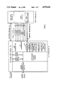
- FIG. 1 shows a block diagram of a system in accordance with the invention
- FIG. 2 shows a general data format of the contents of an exemplary control block of data used in the system of FIG. 1;
- FIG. 3 shows a more specific data format of the control block of FIG. 2;
- FIG. 4 shows a data format of the contents of a controller information block of data used by an I/O controller in the system of FIG. 1;
- FIG. 5 shows a data format of the contents of an interface information block of data used by the I/O controller of FIG. 1;
- FIG. 6 shows a data format of the contents of a unit information block of data used by the I/O controller of FIG. 1;
- FIG. 7 shows a data format of the contents of an extended status information block of data used in the system of FIG. 1;
- FIG. 8 shows the data contents used in the command I/O registers of FIG. 1;
- FIG. 9 shows the data contents used in the status I/O registers of FIG. 1.
- a host computer 10 which includes a host central processor unit (CPU) 11 and a host main memory unit 12 requires communication with external I/O devices via an intermediate I/O controller unit 13 via appropriate buses as described in more detail below.
- CPU central processor unit
- main memory unit 12 requires communication with external I/O devices via an intermediate I/O controller unit 13 via appropriate buses as described in more detail below.
- the I/O controller unit 13 utilizes appropriate host interface units 13A which include a plurality of input and output I/O registers identified as "command" registers 14 and "status" registers 15.
- command registers 14 which receive command signals from host processor 11 over a command/return bus 16 may comprise three such registers 14A, 14B and 14C, identified as registers DOA, DOB, and DOC.
- Return status information is then supplied in such particular embodiment on the command/return bus 16 to the host from status registers 15A, 15B and 15C, identified as registers DIA, DIB and DIC, respectively.
- incoming commands at registers 14 are appropriately processed by controller microprocessor 17 to obtain one or more control blocks of command information stored in the host main memory.
- a control block specifies, inter alia, the command operation to be executed and the location in main memory and at the external device with respect to which a data transfer is to take place.
- Controller 13 then communicates to one of a plurality of external I/O devices via suitable device interface and micro-processor logic 19 in response to such commands.
- transfers of data between the I/O devices and the host main memory are performed via a high speed data transfer channel 20, utilizing appropriate control signals from the micro-processor 17, via high speed data channel bus 21. Transfers of control block information and initiation information between the controller 13 and host main memory 12 also occurs via high speed data channel 20.
- control signals can be transferred between the host processor and the I/O controller processor via dedicated lines 22-28 as described in more detail below.
- the I/O controller 13 is provided with access to the host main memory by the micro-processor 17 via the high speed channel 20.
- a command is received from the host CPU 11 and is placed in the command registers 14, such command can be appropriately interpreted by micro-processor 17 as requiring a sequence of one or more commands each command being part of a control block of information required to execute such command, i.e., an operation with respect to a selected external I/O device.
- Such sequence of control blocks can be pre-stored in the host main memory 12 so that when the micro-processor of the I/O controller 13 interprets a programmed I/O command from the host CPU 11, the controller successively accesses the entire sequence of control blocks from the host memory 12, fetching each block from main memory for storage in the I/O controller local memory 18 for execution before fetching the next control block of the sequence for each successive execution thereof.
- the controller is also arranged so that, during the execution of a command in one sequence,it can respond to another subsequent programmed I/O command from the host CPU for accessing a second sequence of control blocks, each one of which can be successively fetched for storage in local memory 18. In this way a plurality of input programmed I/O commands from the host CPU 11 can be used to generate a plurality of associated control block sequences, or lists, the control blocks of which can also be successively stored in local memory 18.
- the local memory may have stored therein a large number of separate control blocks, one from each of a plurality of separate control block lists, any one of which can be selected in accordance with a predetermined algorithm, for example, to be executed at any one time.
- the total number of commands required to be issued by the host CPU is considerably reduced and the latter can be utilized for performing other operations which it normally could not perform in a conventional I/O interface system since the host would have to use that time to issue separately each one of the large number of commands for each such command sequence in previously known systems.
- control block (command) sequences concern themselves with the transfer of information to or from the same specified I/O device
- the micro processor 17 may utilize a predetermined algorithm for executing the commands from all of the lists involved which provides for the most effective, or optimized, movement of the I/O device access mechanism (e.g., a Read/Write head) with respect to the I/O device (e.g., a disk).
- the I/O processor may be required by the host processor to execute the commands in an established sequence in accordance with an established priority of operation thereof.
- the execution of the commands provides for a transfer of information via the high speed data channel 20 to the host memory 12 where it can be appropriately utilized by the host CPU for whatever operation it desired to perform.
- the registers 15 provide return information to the host CPU notifying the latter that such sequence has been completed and providing suitable status information concerning the state of the I/O controller 13.
- I/O controller shares memory space in main memory 12 with the host processor, such operation reduces the number of commands required from the host CPU when dealing with I/O devices and permits the most efficient execution of commands vis-a-vis such devices so that the overall control and data transfer operation can be optimized with respect to several programmed I/O commands from the host processor.
- control block which format is established for all control blocks, is shown in FIGS. 2 and 3.
- the control block comprises twenty words of 16 bits each, a first selected group of words including information placed therein by the host computer, a second selected group of status return words supplied in a shared manner by the I/O controller and the host processor, and a third group of status error words supplied by the I/O controller.
- word groups are shown more specifically in FIG. 3.
- the host provides in words 0 and 1 a linking address (comprising a high, or most significant, portion and a low, or least significant, portion) which represents the address of the next successive control block of a sequence, or list, thereof.
- An address of zero indicates that the particular control block in question is the last one of a sequence.
- the I/O controller processor can always identify the location of the next control block of the sequence which must be fetched.
- Word 2 includes an optional interrupt (I) bit (bit 0) which, when set by the host processor generates an unconditional interrupt of the host by the controller when each control block command has been completed. If not set, the controller generates an interrupt only when a complete list or sequence of control block commands has been completed (i.e., the link address is zero) or if an error occurs.
- I optional interrupt
- Word 2 also includes a "No Retries” bit N (bit 1) which, when set by the host processor, prevents any retry for any kind of error (hard or soft) so that, in effect, the controller treats all errors as hard errors. If N is not set, the errors are treated in accordance with the controller information block discussed below.
- Bits 6-15 of word 2 contain the operation code which identifies the operation to be performed in accordance with the following octal coding, for example:
- Words 3-6 provide main memory address (or pointers thereto) via the host memory page listings and the starting address on such page at which the data transfer will commence in main memory.
- Bit 0 (M) of word 5 when set, indicates that the address is a logical address which requires a mapping into a physical memory. If not set, the address supplied by the host is a physical address.
- Words 7 and 8 identify the address on the selected external device (e.g., the sector of a disk for the data transfer), while word 9 identifies the device, or unit, itself.
- Word 10 is shared by the host (on a command) and the I/O controller (on a return), the command identifying how much data is to be transferred (transfer count) between the selected device and the host main memory.
- the I/O controller specifies the amount of data (transfer count) that has actually been transfered.
- Word 11 is also effectively shared by host and controller.
- the host supplies all zeroes which indicates to the controller that the host is ready for the controller to execute the command involved.
- the controller supplies information concerning the completed execution of the command as follows:
- words 14-20 include information supplied by the I/O controller concerning the status of various error situations which may have arisen during the execution of the command (word 14), the status of the selected external device in this connection (word 15), the total number of error retries performed (word 16), the total amount of data (e.g., data sectors on a disk) which was transferred before an error occurred (word 17), the address of the selected device where the error occurred, e.g., a physical cylinder address on a disk (word 18) and the physical head address and physical sector address on a disk (word 19).
- Word 20 identifies a code which represents an error which has occurred with reference to the drive circuitry for the selected device (e.g., disk drive circuitry), e.g., a bus fault, a specified circuit checkpoint error, an error in the drive logic, an error in the position circuitry, a power failure, or an error in the Read/Write circuitry.
- the selected device e.g., disk drive circuitry
- the drive circuitry for the selected device e.g., disk drive circuitry
- each control block which is accessed by the I/O controller upon command from the host processor, provides sufficient information for the controller micro-processor to execute the command involved and to return to the host in the control block further information concerning such execution, i.e., as to whether it has been completed or whether a fault occurred to prevent the transfer of some or all of the data.
- certain initialization information is provided to the host by the controller to inform the host about the status of both the controller and units which are available for data transfer via the controller.
- Such information transfer utilizes predefined information blocks which are stored in the controller's local memory and are peculiar to the particular I/O controller involved.
- the host processor can modify the controller's operation to some extent by modifying the information in the information blocks supplied to it by the controller so that the host (i.e., the user) has some flexibility in how he wishes to handle the data transfer operation.
- the system utilizes three such information blocks as described below. Such information blocks are transferred to the host main memory, modified if desired by the host and returned to the I/O controller local memory.
- One information block can be designated as a controller information block, shown in FIG. 4 as comprising two 16-bit words.
- This block is programmable and contains device specific information concerning the controller, in this case the manner in which the controller is to handle the retrying of errors (in cases where an error has occurred and the controller repeats the command execution a selected number of time to see if the error is one which is intermittent and will, when not present, permit a successful completion of the command, i.e., a "soft" error).
- Word 0 defines the maximum number of times the controller will attempt to execute a control block for a device, or unit, which is reporting an error.
- Word 1 defines the maximum number of times the controller will attempt to execute a control block for an error which arises in the controller itself (bits 0-7) and the maximum number of correction retries the controller will attempt to read data with an error in the error correction code (ECC) (bits 8-15).
- ECC error correction code
- the controller processor can be arranged so that a read retry is not attempted unless the controller retry count is exceeded and the controller senses an ECC error. If during execution of a control block the maximum number of retries in this information block is exceeded in any case the type of error is indicated in the appropriate return control block words and also indicates therein the number of retries attempted, as discussed above.
- a second information block can be designated as an interface information block and contains universal information concerning a specified device which the host processor needs to know in order to handle a data transfer with respect to such device.
- the type of information in this block is the same for any device with which the controller is in communication and such information cannot be modified by the host processor.
- the interface information block is shown in FIG. 5 as comprising, in a particular embodiment under discussion, seven 16-bit words.
- Word 0 contains the device type code and identifies which type of device is being communicated with, while word 1 contains the microcode revision number which identifies the particular instruction set which is currently executed by the I/O controller.
- Word 2 defines the highest unit number to indicate how many units are being handled by the controller and is fixed for any particular controller.
- Word 3 defines the total number of control blocks which can be stored in the local memory of the controller (in a particular embodiment, for example, a controller may be capable of storing up to 30 control blocks) and is fixed for a particular controller.
- Word 3 also includes a legal count code which defines the type of data units which are being transferred with respect to the particular type of external device being used, e.g., data sectors for a disk device, data bytes for a tape device, etc. In a particular embodiment, for example, the legal count code may identify sectors, bytes, words or pages.
- Word 4 can be used as a masking word so as to cause an interrupt if any bits in the control block unit status word (word 15 of the control block) change.
- Word 5 defines the number of control block return status words (i.e., words 10-20 of a control block) are to be returned to the host in a returned control block, the host processor being capable of modifying this number as desired. For example, if the host specifies "0" the controller will not return any information in words 10-20 of a control block after it completes a control block. If the host specifies any number of words from 1 to 11 and no error occurs, the controller will supply information in return control block words 10 and 11 only. If an error occurs the controller will return information only for the return control block words requested by the host.
- Words 6 and 7 include masking information and contain bit 0 (word 6) which indicates, when set, that page number list addresses of a control block are two words long and, when not set, that page number list addresses are one word long.
- the remaining lists of words 6 and 7 form a 31-bit mask word which is logically ANDed with the page number list entry to produce a physical page number.
- a further information block designated as a unit information block comprising six 16-bit words is shown in FIG. 6.
- a unit information block is available for each unit with which the controller is in communication and includes all the information, both universal and device-specific, which is needed by the host processor for handling data transfers with respect to such unit. Accordingly, the host processor cannot modify any of the information in the unit information block, except for information in bits 0-3 of word 0 thereof, is discussed below.
- word 0 bits 9-15
- Word 1 defines the device configuration.
- the disk configuration is defined as follows:
- Words 2 and 3 define the number of logical blocks, i.e., for a disk, the number of disk sectors, which can be accessed on the device.
- Word 4 defines the number of data bytes per logical block of the device (e.g., the number of data bytes per sector).
- word 5 defines the number of cylinders per disk, while word 6 defines both the number of heads per disk and the number of sectors per disk track. None of the values (other than bits 0-3 of word 0) can be changed.
- Bit 0 of word 0 controls the type of execution which is to be used when the controller has stored control blocks from more than one control block list.
- the I/O controller stores in its local memory only one control block from each of a plurality of control block lists (presuming the host processor has enqueued more than one such list).
- the controller can only execute one of such control blocks at a time, either by completing the control block of a given list which it is currently executing and then executing either the next successive control block in the same list or a currently stored control block from another list (either the next successive list or any other list that may have a control block stored in local memory).
- the I/O controller may be arranged, for example, to operate in a selected manner, which might be designated as a normal or non-optimized manner, as follows.
- the controller completes a control block of a particular list for a given external unit, if the next control block of that same list specifies the same unit, the controller executes such next control block. Otherwise, the controller executes a control lock of the next successive list in the queue of lists which require execution for the same unit.
- controller may be arranged so that it enqueues a control block list behind all other lists for a specified unit (1) if a Start List command from he processor (processor commands are discussed in more detail below) requires the controller to start a new list, or (2) if a new unit is specified in the next control block of a currently executing list.
- Start List command from he processor (processor commands are discussed in more detail below) requires the controller to start a new list, or (2) if a new unit is specified in the next control block of a currently executing list.
- Such "normal" operation in effect preserves the execution order of control blocks in a list and preserves the order of the lists when more than one unit is not contained in a single list. Such operation occurs so long as the optimization bit 0 (the "0" bit) of word 0 is not set, i.e., so long as the host processor does not request optimization by setting the 0 bit.
- Bit S (bit 1 of word 0) represents an error interrupt bit. If set by the host, the controller must interrupt the host on any error which occurs during the execution of a control block. If not set, an interrupt occurs only when all the retry counts in the controller information block have been exhausted and the error is then "hard".
- Bit M (bit 2 of word 0) represents a modified bit which, when set by the host, informs the controller that the host has modified the information of a sector of the disk on a write operation. If not set a write operation clears the modified bit.
- the A bit (bit 3 of word 0) is used when an external unit has dual ports permitting two controllers to access the same unit. For such units three operations can occur: (1) a "reserve” operation in which a device is reserved for exclusive use by one controller via one port (another controller cannot even use the other port); (2) a “release” operation which frees a device from exclusive use by a controller so that a second controller can use the unit through the other port (the unit is automatically released by a controller after each use); and (3) a "trespass” operation which overrides a controller's exclusive use of a unit at any time, e.g., a second controller can override, via a second port, a first controller which has currently reserved use of the unit via the first port.
- Such operations are controlled through use of the A bit in conjunction with the 0 bit as follows.
- a controller reserves a unit before executing a control block and keeps the unit reserved so long as current control blocks specify such unit. When the current control blocks no longer specify that unit the controller releases the reserved unit.
- a controller reserves a unit before executing a control block but immediately releases it after execution. If this condition is set for two controllers using the same unit, for example, the controllers in effect alternate their use of the unit.
- a controller reserves a unit before executing a control block and after execution checks the control block optimization queue for that drive. If further control blocks are awaiting execution for such unit the controller executes the next control block in the queue and does not release the unit until all such control blocks in the queue are executed.
- the "trespass" condition only occurs for a programmed I/O command therefor issued by the host processor as discussed with reference to programmed I/O commands below. Such a command is normally rarely used but can be issued, for example, if a user requires immediate access to a unit.
- an extended status information block can be stored by the controller in its local memory. If an error occurs the error can usually be resolved using the error status information provided in the status registers (discussed below) or in the control block error status words. However, if the error is severe (effectively not resolvable using such information) it may be necessary to supply additional (extended) information to the host concerning the error status, such information being supplied by generating an extended status information block of thirty-two 16-bit words, as shown in FIG. 7.
- the words generally contain information as follows:
- An extended status information block is maintained for each unit accessed by the controller and provides status information for each error which occurs (when the S bit of the unit information block is set the status information at the time such error occurred is contained in the extended status block while if the S bit is not set the extended status block reflects the last error that occurred).
- the host can retrieve the extended status block for a particular unit from the controller's local memory by issuing the appropriate command therefor as discussed below. After storing an extended status block in main memory the host must issue a re-start command to begin execution again, also as discussed below.
- the commands utilized by the host processor and supplied from the host accumulators to the command registers 14 comprise a programmed I/O (PIO) command set for controlling the operation of the controller and the transfer of control blocks and information blocks.
- PIO programmed I/O
- Such commands are issued by the host in response to appropriate assembler I/O instructions utilized by the host in accordance with the operation of the host processor.
- the host processor may be a processor of the type made and sold by Data General Corporation under the designation Eclipse®, one such model thereof being the MV-8000® model which is currently available to those in the art and which includes suitable I/O instructions.
- Other processors available to the art can be used by those in the art and their use in the context described would be within the skills of those in the art from the description presented here.
- control blocks form a command set for the external device drive interface, e.g., a set of disk commands.
- the control blocks are loaded with a device command operation code and the control block is executed by issuing a PIO command from the host processor via an assembler I/O instruction which decodes the assembler instruction to produce the required PIO command.
- the controller responds to the PIO commands via the controller registers, i.e., the command registers 14 (DOA, DOB and DOC), and the return status registers 15 (DIA, DIB and DIC), each containing a 16-bit word in the particular embodiment disclosed.
- the assembler instructions transfer information between host accumulators and the controller registers 14 and 15, i.e., PIO commands from the host to registers 14 and status and interrupt information from registers 15 to host.
- FIG. 8 depicts the format of PIO commands issued to command registers DOA, DOB and DOC.
- the registers 14A and 14B contain the command arguments while register 15C contains the PIO command code and a return bit (the unused bits are all 0's). If the arguments are addresses (as is usually the case, for example, when the command requires the I/O controller to fetch a control block at a specified location in main memory) register A contains the high order word (most significant bits) and register B the low order word (least significant bits).
- the return bit R determines whether the controller will generate a synchronous interrupt when the PIO command has been completed (R is set) or whether such interrupt is not generated (R is not set).
- the command registers can be loaded in any order so long as the controllers' "busy" flag (on line 26) is clear (not set) . The execution of the PIO command will not begin until the host issues a start S-pulse on line 24.
- the I/O controller loads interrupt return information into status registers 15. Interrupts in the system described can be asynchronous or synchronous in nature, the former occurring after a control block error or when the controller completes its execution of a control block and the latter occurring when the controller completes a PIO command.
- FIG. 9 depicts the return information format in registers 15 wherein registers 15A and 15B contain interrupt information and register 15C contains status information ("status") concerning the command state, further command completion status bits (“CCS") indicating the type of interrupt and either the original command code and return request bit (as originally loaded into bits 6-15 of register 14C) if a synchronous interrupt occurs or interrupt code if an asynchronous interrupt occurred.
- the status bits 0-3 are valid only when the "Busy” flag is clear, while the remaining bits of all the registers are valid only when the "Done" flag is set.
- the Busy and Done flags indicate whether the I/O controller is performing an operation or whether it has completed one and their settings can be checked before issuing a PIO command.
- the Busy flag is set as soon as the host issues an S-pulse and remains set until execution of the entire PIO command is completed so that no further PIO commands can be issued to registers 14 until the Busy flag is clear.
- the Done flag whether set for an asynchronous or a synchronous interrupt, indicates that the status registers 15 contain valid return information. Selected bits of the I/O assembler instruction are used to control selected functions of the I/O controller via the pulse signals on dedicated lines 22-25.
- the R-pulse resets all internal I/O controller logic, clears the Busy and Done flags and all pending interrupt requests.
- the S-pulse starts a PIO command, thereby setting the Busy flag and clearing the Done flag.
- the C-pulse services an interrupt and clears the Done flag and the pending interrupt.
- the P pulse sets an internal controller state that causes an Interrupt (Line 28) to be generated when the controller goes Not Busy if the Done flag is clear.
- Appendix A shows a table of exemplary PIO commands which can be issued by the host processor and supplied to registers 14 the contents of each such register being listed therein for each such command
- the specific encodings of the registers, and particularly the DOC register 15C, are exemplary only for use in a particular embodiment of the invention and illustrate typical encodings.
- command operating codes in the register 15C can be as follows:
- the I/O controller loads its status registers 15 with the command return information and sets the Done flag when the Busy flag clears if the return request bit R is set. If the latter is not set the status registers are not loaded nor is the Done flag set. Setting the Done flag generates an interrupt request to the host.
- the controller loads error return information into the status registers 15 and sets the Done flag regardless of whether the return request bit is set.
- the registers 15 transfer their contents to specified host accumulators so that the host can determine interrupt recovery procedures.
- the host interrupt routine services such interrupt by issuing a C-pulse.
- Selected bits (bits 4-5) of the status register 15C indicate whether the interrupt is asynchronous or synchronous while other selected bits (bits 6-15) are coded to indicate the kind of error which occurred. If a synchronous interrupt occurs such bits merely "echo" the original command code and return request bit setting of the most recent command sent to the controller.
- the status bits 0-3 of register 15C are valid whenever Busy is clear, while the remaining bits thereof are valid whenever the Done flag is set. Additional return information can be transferred via registers 15A and 15B. Whenever such information represents an address, register 15A contains the higher order bits and register 15B the lower order bits. Such register contents are valid when the Done flag is set.
- the table of Appendix B lists different types of exemplary asynchronous interrupts while the table of Appendix C lists different types of exemplary synchronous interrupts and both tables describe the contents of registers 15 in each case for a particular embodiment of the invention.
- the controller completion status determined by bits 4-5 of register 15C identifies the following exemplary types of interruptions.
- Exemplary types of asynchronous interrupt error codes as used in bits 6-15 of status register 15C are identified as follows:
- the controller Upon the occurrence of an error identified by the error code the controller utilizes an appropriately predetermined interrupt routine with respect thereto.
- Initialization commands can be used to transfer different use options available to the system during operation, such as address mapping, interface, controller and device (unit) operations.
- Diagnostic commands are used to perform selected diagnostic tests on the controller in the event of controller errors.
- Extended status commands are used to examine the state of the device subsystem when an error occurs.
- List control commands are used to perform control block operations. State independent commands can be used to initiate the diagnostic command set or to reset the controller.
- Valid While Reset commands can be used to move initial Load Programs into the host main memory or to cause the controller to load its microcode control store.
- the host may be a Data General Corporation MV-8000® system while the controller micro processor may be of the type made and sold by Data General Corporation under the the designations Micro-NOVA® or Micro Eclipse® microprocessors.
- the high speed data transfer channel may be of the type described in U.S. Pat. No. 4,403,282, issued Sept. 6, 1982, a high speed data transfer channel often referred to as a "burst multiplex channel" as used, for example, and available in Data General Corporation's M-600 data processing system.
Abstract
A data processing system which includes a host processor and an input/output (I/O) controller unit for controlling communication with I/O devices. The I/O controller unit responds to a plurality of I/O commands from the host processor each of which is associated with one of a plurality of control block lists each containing one or more control commands. The I/O controller unit can access and store control commands from each of the plurality of control block lists and execute the stored commands from such lists in a selected order for providing the most effective execution thereof.
Description
This is a continuation of co-pending application Ser. No. 496,173 filed on May 19, 1983, now abandoned.
This invention relates generally to data processing systems and, more particularly, to a unique interface control system for providing communication between a host computer processor and an input/output control processor which in turn is in communication with external or peripheral devices.
In order to provide communication between a host computer and a plurality of external input/output (I/O) units, or devices, such as disks, tapes, printers, display devices, etc., it is effective for data processing systems to utilize an intermediate control processor which communicates with the host computer processor and in turn communicates with a large number of I/O devices. Control of which devices require the transfer of data to and from the host computer then resides in the intermediate I/O controller.
In most conventional systems utilizing such approach the host processor supplies an appropriate command to an I/O controller processor which in turn interprets such commands so that the I/O device required can be identified and the appropriate data processing and transfer operation can occur. The host normally supplies such commands in sequence and the I/O processor processes such commands in such sequence. If the I/O processor is busy with a particular command requiring the servicing of a specified I/O device the host must wait until that process has been completed before it can issue subsequent commands related either to the same or to a different I/O device. Such an approach normally requires the transfer of a relatively large number of commands from the host processor and does not permit the controller to make the most effective use of a sequence of such commands. For example, if the host processor desires to access blocks of data from, or to store blocks of data on, an I/O device such as a disk, for example, such data blocks may reside at various locations on the disk and the Read/Write head which accesses the device must move from one location to the other in accordance with the particular command received by the I/O controller. Since in many cases the sequence of movements of the head on a particular disk required for a specific sequence of commands may not represent the most efficient movement for transferring all of the data required by such sequence, it is desirable to establish a more effective manner for controlling the data transfer to or from the same I/O device in an optimized fashion.
It is further desirable to arrange for the I/O controller to operate in response to a reduced number of commands from the host processor so that the host processor can transfer the desired information with the least amount of host processor time and with reduced I/O communication overhead so that the host processor can perform other tasks in the meanwhile.
The system in accordance with the invention utilizes an I/O controller which is capable of receiving a single command from the host processor, which command can then be utilized to generate in turn an entire block or list of sequential commands which are pre-stored in the host's main memory, such memory thereby being effectively shared by both the host processor and the I/O controller. The host then need only supply a single host programmed I/O command to generate a relatively large number of sequential controller I/O commands associated therewith in order to perform any particular overall data transfer, rather than having the host processor supply an entire sequence of such commands for that particular data transfer operation.
Further, the I/O controller is arranged in accordance with the invention so that it can respond to several successive host processor programmed I/O commands and in turn generate several corresponding blocks or lists of command sequences, appropriate commands of each sequence being stored in the I/O controller local memory at any one time for suitable execution. The I/O controller can then execute such command lists in accordance with a suitably selected procedure as desired. Thus, the I/O controller may be controlled to provide a selected sequence of command list execution in which a complete command list is executed before a next successive complete command list is executed. Alternatively, an I/O controller may be arranged to select a more efficient procedure in which commands from several different command lists can be executed in any desired optimized order, i.e., an order in which commands can be selected from any of the command lists so that data transfers to and from the same I/O device can be most efficiently executed. Alternatively, either of such procedures may further be arranged to take into account appropriate priorities which may be established for such command lists by the host processor, for example, and perform such command lists in accordance with the established priorities.
Further, the I/O controller can be arranged to permit the host processor to utilize initialization commands independently of the programmed I/O commands, so as to cause the controller to operate in a selected one of a number of different ways as desired by the user, for example, with respect to the treatment of errors, the selection of the type of status information required by the host processor, the selection of which process to use when transferring information to or from a particular I/O device in accordance with a sequence of commands, and the like.
The invention can be described in more detail with the help of the accompanying drawings wherein
FIG. 1 shows a block diagram of a system in accordance with the invention;
FIG. 2 shows a general data format of the contents of an exemplary control block of data used in the system of FIG. 1;
FIG. 3 shows a more specific data format of the control block of FIG. 2;
FIG. 4 shows a data format of the contents of a controller information block of data used by an I/O controller in the system of FIG. 1;
FIG. 5 shows a data format of the contents of an interface information block of data used by the I/O controller of FIG. 1;
FIG. 6 shows a data format of the contents of a unit information block of data used by the I/O controller of FIG. 1;
FIG. 7 shows a data format of the contents of an extended status information block of data used in the system of FIG. 1;
FIG. 8 shows the data contents used in the command I/O registers of FIG. 1; and
FIG. 9 shows the data contents used in the status I/O registers of FIG. 1.
As can be seen in FIG. 1, a host computer 10 which includes a host central processor unit (CPU) 11 and a host main memory unit 12 requires communication with external I/O devices via an intermediate I/O controller unit 13 via appropriate buses as described in more detail below.
The I/O controller unit 13 utilizes appropriate host interface units 13A which include a plurality of input and output I/O registers identified as "command" registers 14 and "status" registers 15. In a particular embodiment, for example, command registers 14 which receive command signals from host processor 11 over a command/return bus 16 may comprise three such registers 14A, 14B and 14C, identified as registers DOA, DOB, and DOC. Return status information is then supplied in such particular embodiment on the command/return bus 16 to the host from status registers 15A, 15B and 15C, identified as registers DIA, DIB and DIC, respectively. As discussed in more detail below, incoming commands at registers 14 are appropriately processed by controller microprocessor 17 to obtain one or more control blocks of command information stored in the host main memory. A control block specifies, inter alia, the command operation to be executed and the location in main memory and at the external device with respect to which a data transfer is to take place. Controller 13 then communicates to one of a plurality of external I/O devices via suitable device interface and micro-processor logic 19 in response to such commands. In the particular system disclosed, transfers of data between the I/O devices and the host main memory are performed via a high speed data transfer channel 20, utilizing appropriate control signals from the micro-processor 17, via high speed data channel bus 21. Transfers of control block information and initiation information between the controller 13 and host main memory 12 also occurs via high speed data channel 20.
In addition to various host programmed I/O commands and controller return information which are transferred on bi-directional bus 16, further control signals can be transferred between the host processor and the I/O controller processor via dedicated lines 22-28 as described in more detail below.
Before discussing the control signals which are utilized by the I/O controller/host interface 13A it is desirable to discuss generally the advantages of utilizing the configuration of the invention as generally disclosed in the embodiment of FIG. 1.
The I/O controller 13 is provided with access to the host main memory by the micro-processor 17 via the high speed channel 20. When a command is received from the host CPU 11 and is placed in the command registers 14, such command can be appropriately interpreted by micro-processor 17 as requiring a sequence of one or more commands each command being part of a control block of information required to execute such command, i.e., an operation with respect to a selected external I/O device. Such sequence of control blocks can be pre-stored in the host main memory 12 so that when the micro-processor of the I/O controller 13 interprets a programmed I/O command from the host CPU 11, the controller successively accesses the entire sequence of control blocks from the host memory 12, fetching each block from main memory for storage in the I/O controller local memory 18 for execution before fetching the next control block of the sequence for each successive execution thereof. The controller is also arranged so that, during the execution of a command in one sequence,it can respond to another subsequent programmed I/O command from the host CPU for accessing a second sequence of control blocks, each one of which can be successively fetched for storage in local memory 18. In this way a plurality of input programmed I/O commands from the host CPU 11 can be used to generate a plurality of associated control block sequences, or lists, the control blocks of which can also be successively stored in local memory 18.
Thus, the local memory may have stored therein a large number of separate control blocks, one from each of a plurality of separate control block lists, any one of which can be selected in accordance with a predetermined algorithm, for example, to be executed at any one time. The total number of commands required to be issued by the host CPU is considerably reduced and the latter can be utilized for performing other operations which it normally could not perform in a conventional I/O interface system since the host would have to use that time to issue separately each one of the large number of commands for each such command sequence in previously known systems.
For example, in some cases where more than one of the control block (command) sequences (lists) concern themselves with the transfer of information to or from the same specified I/O device, it may be desirable to assure that such data transfers occur in the most efficient manner. In such a case it may be desirable for the micro processor 17 to utilize a predetermined algorithm for executing the commands from all of the lists involved which provides for the most effective, or optimized, movement of the I/O device access mechanism (e.g., a Read/Write head) with respect to the I/O device (e.g., a disk).
Alternatively, the I/O processor may be required by the host processor to execute the commands in an established sequence in accordance with an established priority of operation thereof. In any event, the execution of the commands provides for a transfer of information via the high speed data channel 20 to the host memory 12 where it can be appropriately utilized by the host CPU for whatever operation it desired to perform. Once a complete sequence of commands from any control block list has been performed, the registers 15 provide return information to the host CPU notifying the latter that such sequence has been completed and providing suitable status information concerning the state of the I/O controller 13.
Because the I/O controller shares memory space in main memory 12 with the host processor, such operation reduces the number of commands required from the host CPU when dealing with I/O devices and permits the most efficient execution of commands vis-a-vis such devices so that the overall control and data transfer operation can be optimized with respect to several programmed I/O commands from the host processor.
In order to better understand such operation, the format of a control block, which format is established for all control blocks, is shown in FIGS. 2 and 3. As seen in FIG. 2, in a particular embodiment thereof, the control block comprises twenty words of 16 bits each, a first selected group of words including information placed therein by the host computer, a second selected group of status return words supplied in a shared manner by the I/O controller and the host processor, and a third group of status error words supplied by the I/O controller. Such word groups are shown more specifically in FIG. 3.
As can be seen in FIG. 3, the host provides in words 0 and 1 a linking address (comprising a high, or most significant, portion and a low, or least significant, portion) which represents the address of the next successive control block of a sequence, or list, thereof. An address of zero indicates that the particular control block in question is the last one of a sequence. Thus, the I/O controller processor can always identify the location of the next control block of the sequence which must be fetched.
Word 2 includes an optional interrupt (I) bit (bit 0) which, when set by the host processor generates an unconditional interrupt of the host by the controller when each control block command has been completed. If not set, the controller generates an interrupt only when a complete list or sequence of control block commands has been completed (i.e., the link address is zero) or if an error occurs.
Bits 6-15 of word 2 contain the operation code which identifies the operation to be performed in accordance with the following octal coding, for example:
______________________________________
Octal Code     Meaning
______________________________________
000            No Operation
100            Write
101            Write/Verify
104            Write Single Word
105            Write/Verify Single Word
142            Write with Modified Bit Map
200            Read
201            Read/Verify
205            Read/Verify Single Word
210            Read Raw Data
220            Read Headers
242            Read with Modified Bit Map
400            Recalibrate Disk
______________________________________
Words 3-6 provide main memory address (or pointers thereto) via the host memory page listings and the starting address on such page at which the data transfer will commence in main memory. Bit 0 (M) of word 5, when set, indicates that the address is a logical address which requires a mapping into a physical memory. If not set, the address supplied by the host is a physical address.
______________________________________ Bit Meaning if set: ______________________________________ 0 Any CBhard execution error 1Interpretation error 2 Soft errors in execution occurred; controller recovered 3 CB termination by CancelList command 4 ECC correction needed 5 ECC correction failed 6-14 Unused 15 CB Done bit ______________________________________
Although words 12 and 13 in the embodiment under discussion are reserved for future use, words 14-20 include information supplied by the I/O controller concerning the status of various error situations which may have arisen during the execution of the command (word 14), the status of the selected external device in this connection (word 15), the total number of error retries performed (word 16), the total amount of data (e.g., data sectors on a disk) which was transferred before an error occurred (word 17), the address of the selected device where the error occurred, e.g., a physical cylinder address on a disk (word 18) and the physical head address and physical sector address on a disk (word 19). Word 20 identifies a code which represents an error which has occurred with reference to the drive circuitry for the selected device (e.g., disk drive circuitry), e.g., a bus fault, a specified circuit checkpoint error, an error in the drive logic, an error in the position circuitry, a power failure, or an error in the Read/Write circuitry.
Accordingly, each control block, which is accessed by the I/O controller upon command from the host processor, provides sufficient information for the controller micro-processor to execute the command involved and to return to the host in the control block further information concerning such execution, i.e., as to whether it has been completed or whether a fault occurred to prevent the transfer of some or all of the data.
Before transferring one or more control blocks from the host main memory to the I/O controller so that the commands involved can be executed by the controller micro-processor, certain initialization information is provided to the host by the controller to inform the host about the status of both the controller and units which are available for data transfer via the controller. Such information transfer utilizes predefined information blocks which are stored in the controller's local memory and are peculiar to the particular I/O controller involved. Once the host processor is so informed about the particular I/O controller with which it is communicating, the host can modify the controller's operation to some extent by modifying the information in the information blocks supplied to it by the controller so that the host (i.e., the user) has some flexibility in how he wishes to handle the data transfer operation. In the particular embodiment being described the system utilizes three such information blocks as described below. Such information blocks are transferred to the host main memory, modified if desired by the host and returned to the I/O controller local memory.
One information block can be designated as a controller information block, shown in FIG. 4 as comprising two 16-bit words. This block is programmable and contains device specific information concerning the controller, in this case the manner in which the controller is to handle the retrying of errors (in cases where an error has occurred and the controller repeats the command execution a selected number of time to see if the error is one which is intermittent and will, when not present, permit a successful completion of the command, i.e., a "soft" error). Word 0 defines the maximum number of times the controller will attempt to execute a control block for a device, or unit, which is reporting an error. In all cases the words are all zeroes at power up and the controller microcode is arranged to set the information in the information blocks following power up.) Word 1 defines the maximum number of times the controller will attempt to execute a control block for an error which arises in the controller itself (bits 0-7) and the maximum number of correction retries the controller will attempt to read data with an error in the error correction code (ECC) (bits 8-15). For example, in the latter cases the controller processor can be arranged so that a read retry is not attempted unless the controller retry count is exceeded and the controller senses an ECC error. If during execution of a control block the maximum number of retries in this information block is exceeded in any case the type of error is indicated in the appropriate return control block words and also indicates therein the number of retries attempted, as discussed above.
A second information block can be designated as an interface information block and contains universal information concerning a specified device which the host processor needs to know in order to handle a data transfer with respect to such device. The type of information in this block is the same for any device with which the controller is in communication and such information cannot be modified by the host processor. The interface information block is shown in FIG. 5 as comprising, in a particular embodiment under discussion, seven 16-bit words.
A further information block designated as a unit information block comprising six 16-bit words is shown in FIG. 6. A unit information block is available for each unit with which the controller is in communication and includes all the information, both universal and device-specific, which is needed by the host processor for handling data transfers with respect to such unit. Accordingly, the host processor cannot modify any of the information in the unit information block, except for information in bits 0-3 of word 0 thereof, is discussed below.
Before discussing the latter bits, it can be seen that word 0 (bits 9-15) is used to identify the external unit involved (as in word 9 of the control block). Word 1 defines the device configuration. Thus, when the unit is a disk, for example, the disk configuration is defined as follows:
______________________________________ Bit Meaning if set: ______________________________________ 0 MovingHeads 1Fixed Heads 2 Fixed/Removable Media 3 Dual Ported 4-15 Unspecified ______________________________________
With that in mind, the I/O controller may be arranged, for example, to operate in a selected manner, which might be designated as a normal or non-optimized manner, as follows. When the controller completes a control block of a particular list for a given external unit, if the next control block of that same list specifies the same unit, the controller executes such next control block. Otherwise, the controller executes a control lock of the next successive list in the queue of lists which require execution for the same unit. Further the controller may be arranged so that it enqueues a control block list behind all other lists for a specified unit (1) if a Start List command from he processor (processor commands are discussed in more detail below) requires the controller to start a new list, or (2) if a new unit is specified in the next control block of a currently executing list. Such "normal" operation in effect preserves the execution order of control blocks in a list and preserves the order of the lists when more than one unit is not contained in a single list. Such operation occurs so long as the optimization bit 0 (the "0" bit) of word 0 is not set, i.e., so long as the host processor does not request optimization by setting the 0 bit.
If the "0" bit is set, optimization is enabled and the controller can execute current control blocks from any list in any desired order in accordance with any suitably selected algorithm for producing the most efficient transfer of information (e.g., movement of the Read/Write heads) with respect to a given device (e.g., on a given disk). Thus, if five control block lists each contain control blocks for the same unit the controller does not have to complete one list before starting the next. Instead, it may skip from list to list and execute control blocks for the same unit from different control block lists in accordance with a suitably selected and predefined algorithm. In any event, the order of control blocks within a list is preserved.
Bit S (bit 1 of word 0) represents an error interrupt bit. If set by the host, the controller must interrupt the host on any error which occurs during the execution of a control block. If not set, an interrupt occurs only when all the retry counts in the controller information block have been exhausted and the error is then "hard".
Bit M (bit 2 of word 0) represents a modified bit which, when set by the host, informs the controller that the host has modified the information of a sector of the disk on a write operation. If not set a write operation clears the modified bit.
The A bit (bit 3 of word 0) is used when an external unit has dual ports permitting two controllers to access the same unit. For such units three operations can occur: (1) a "reserve" operation in which a device is reserved for exclusive use by one controller via one port (another controller cannot even use the other port); (2) a "release" operation which frees a device from exclusive use by a controller so that a second controller can use the unit through the other port (the unit is automatically released by a controller after each use); and (3) a "trespass" operation which overrides a controller's exclusive use of a unit at any time, e.g., a second controller can override, via a second port, a first controller which has currently reserved use of the unit via the first port. Such operations are controlled through use of the A bit in conjunction with the 0 bit as follows.
When the A bit is not set (the 0 bit is a "don't care") a controller reserves a unit before executing a control block and keeps the unit reserved so long as current control blocks specify such unit. When the current control blocks no longer specify that unit the controller releases the reserved unit.
When the A bit is set and the 0 bit is not set, a controller reserves a unit before executing a control block but immediately releases it after execution. If this condition is set for two controllers using the same unit, for example, the controllers in effect alternate their use of the unit.
When the A bit is set and the 0 bit is also set, a controller reserves a unit before executing a control block and after execution checks the control block optimization queue for that drive. If further control blocks are awaiting execution for such unit the controller executes the next control block in the queue and does not release the unit until all such control blocks in the queue are executed.
The "trespass" condition only occurs for a programmed I/O command therefor issued by the host processor as discussed with reference to programmed I/O commands below. Such a command is normally rarely used but can be issued, for example, if a user requires immediate access to a unit.
In addition to control blocks and initiation information blocks discussed above, an extended status information block can be stored by the controller in its local memory. If an error occurs the error can usually be resolved using the error status information provided in the status registers (discussed below) or in the control block error status words. However, if the error is severe (effectively not resolvable using such information) it may be necessary to supply additional (extended) information to the host concerning the error status, such information being supplied by generating an extended status information block of thirty-two 16-bit words, as shown in FIG. 7. The words generally contain information as follows:
______________________________________
Words Block Name   Contents
______________________________________
0-1   Ending Memory
                   Control information and the high
      Address      speed channel
 2-18 Controller   A dump of the controller's registers.
      Error Report This dump contains disk information
                   generated before and after an error.
19-23 --           Unused; all zeros.
24-29 Drive Error  An error code and drive status
      Report       information.
30-31 --           Unused; all zeros.
______________________________________
An extended status information block is maintained for each unit accessed by the controller and provides status information for each error which occurs (when the S bit of the unit information block is set the status information at the time such error occurred is contained in the extended status block while if the S bit is not set the extended status block reflects the last error that occurred). The host can retrieve the extended status block for a particular unit from the controller's local memory by issuing the appropriate command therefor as discussed below. After storing an extended status block in main memory the host must issue a re-start command to begin execution again, also as discussed below.
The commands utilized by the host processor and supplied from the host accumulators to the command registers 14 comprise a programmed I/O (PIO) command set for controlling the operation of the controller and the transfer of control blocks and information blocks. Such commands are issued by the host in response to appropriate assembler I/O instructions utilized by the host in accordance with the operation of the host processor. for example, the host processor may be a processor of the type made and sold by Data General Corporation under the designation Eclipse®, one such model thereof being the MV-8000® model which is currently available to those in the art and which includes suitable I/O instructions. Other processors available to the art can be used by those in the art and their use in the context described would be within the skills of those in the art from the description presented here. In this context, control blocks, as described above, form a command set for the external device drive interface, e.g., a set of disk commands. The control blocks are loaded with a device command operation code and the control block is executed by issuing a PIO command from the host processor via an assembler I/O instruction which decodes the assembler instruction to produce the required PIO command.
The controller responds to the PIO commands via the controller registers, i.e., the command registers 14 (DOA, DOB and DOC), and the return status registers 15 (DIA, DIB and DIC), each containing a 16-bit word in the particular embodiment disclosed. The assembler instructions transfer information between host accumulators and the controller registers 14 and 15, i.e., PIO commands from the host to registers 14 and status and interrupt information from registers 15 to host.
FIG. 8 depicts the format of PIO commands issued to command registers DOA, DOB and DOC. As can be seen, the registers 14A and 14B contain the command arguments while register 15C contains the PIO command code and a return bit (the unused bits are all 0's). If the arguments are addresses (as is usually the case, for example, when the command requires the I/O controller to fetch a control block at a specified location in main memory) register A contains the high order word (most significant bits) and register B the low order word (least significant bits). A selected bit (e.g., bit 0) of register 14A can be used to indicate whether the address is a physical address (bit 0=0) or a logical address (bit 0=1). The return bit R determines whether the controller will generate a synchronous interrupt when the PIO command has been completed (R is set) or whether such interrupt is not generated (R is not set). The command registers can be loaded in any order so long as the controllers' "busy" flag (on line 26) is clear (not set) . The execution of the PIO command will not begin until the host issues a start S-pulse on line 24.
The I/O controller loads interrupt return information into status registers 15. Interrupts in the system described can be asynchronous or synchronous in nature, the former occurring after a control block error or when the controller completes its execution of a control block and the latter occurring when the controller completes a PIO command.
FIG. 9 depicts the return information format in registers 15 wherein registers 15A and 15B contain interrupt information and register 15C contains status information ("status") concerning the command state, further command completion status bits ("CCS") indicating the type of interrupt and either the original command code and return request bit (as originally loaded into bits 6-15 of register 14C) if a synchronous interrupt occurs or interrupt code if an asynchronous interrupt occurred. The status bits 0-3 are valid only when the "Busy" flag is clear, while the remaining bits of all the registers are valid only when the "Done" flag is set.
The Busy and Done flags indicate whether the I/O controller is performing an operation or whether it has completed one and their settings can be checked before issuing a PIO command. The Busy flag is set as soon as the host issues an S-pulse and remains set until execution of the entire PIO command is completed so that no further PIO commands can be issued to registers 14 until the Busy flag is clear. The Done flag, whether set for an asynchronous or a synchronous interrupt, indicates that the status registers 15 contain valid return information. Selected bits of the I/O assembler instruction are used to control selected functions of the I/O controller via the pulse signals on dedicated lines 22-25. The R-pulse resets all internal I/O controller logic, clears the Busy and Done flags and all pending interrupt requests. The S-pulse starts a PIO command, thereby setting the Busy flag and clearing the Done flag. The C-pulse services an interrupt and clears the Done flag and the pending interrupt. The P pulse sets an internal controller state that causes an Interrupt (Line 28) to be generated when the controller goes Not Busy if the Done flag is clear.
Appendix A shows a table of exemplary PIO commands which can be issued by the host processor and supplied to registers 14 the contents of each such register being listed therein for each such command The specific encodings of the registers, and particularly the DOC register 15C, are exemplary only for use in a particular embodiment of the invention and illustrate typical encodings.
For example, command operating codes in the register 15C can be as follows:
______________________________________ Octal Code Command Name ______________________________________ 000 Program Load 002 Begin 024 Diagnostic Mode (Enter/Exit) 026 Set Mapping Information 027 Get Mapping Information 030 Set Interface Information 031 Get Interface Information 032 Set Controller Information 033 Get Controller Information 034 Set Unit Information 035 Get Unit Information 040 GetExtended Status 0 041 GetExtended Status 1 042 GetExtended Status 2 043 GetExtended Status 3 100 Start List 103 Start List (High Priority) 116 Restart 123 Cancel List 131 Unit Status 132 Trespass 133 Get List Status 777 Reset ______________________________________
When the particular PIO command is completely executed the I/O controller loads its status registers 15 with the command return information and sets the Done flag when the Busy flag clears if the return request bit R is set. If the latter is not set the status registers are not loaded nor is the Done flag set. Setting the Done flag generates an interrupt request to the host.
If the PIO command results in an error, the controller loads error return information into the status registers 15 and sets the Done flag regardless of whether the return request bit is set. The registers 15 transfer their contents to specified host accumulators so that the host can determine interrupt recovery procedures. The host interrupt routine services such interrupt by issuing a C-pulse.
Selected bits (bits 4-5) of the status register 15C indicate whether the interrupt is asynchronous or synchronous while other selected bits (bits 6-15) are coded to indicate the kind of error which occurred. If a synchronous interrupt occurs such bits merely "echo" the original command code and return request bit setting of the most recent command sent to the controller. The status bits 0-3 of register 15C are valid whenever Busy is clear, while the remaining bits thereof are valid whenever the Done flag is set. Additional return information can be transferred via registers 15A and 15B. Whenever such information represents an address, register 15A contains the higher order bits and register 15B the lower order bits. Such register contents are valid when the Done flag is set.
The table of Appendix B lists different types of exemplary asynchronous interrupts while the table of Appendix C lists different types of exemplary synchronous interrupts and both tables describe the contents of registers 15 in each case for a particular embodiment of the invention.
The controller completion status determined by bits 4-5 of register 15C identifies the following exemplary types of interruptions.
______________________________________
 ##STR1##
______________________________________
Bits Name     Contents or Function
______________________________________
0-3  Status   The controller execution state (see
              Chapter 4).
4-5  CCS      The controller completion status:
______________________________________
        Bit
        Setting
               Meaning
______________________________________
        00     Asynchronous interrupt occurred
        01     PIO illegal command error: invalid
               command code
        10     PIO command execution error:
               unsuccessful command execution
        11     PIO command completed: successful
               command execution
______________________________________
Exemplary types of asynchronous interrupt error codes as used in bits 6-15 of status register 15C are identified as follows:
______________________________________ Octal Interrupt Code Name ______________________________________ 1 Null Interrupt 2 Controller Interrupt 3 CB Execution Error:Soft Errors 4 CB Execution Error:Hard Errors 5 NoErrors 6 CB Termination Error: CancelList 7 Soft Errors: S Bit Set 10 CB Interpretation Error: Status Word notO 11 CB Interpretation Error:Illegal CB Command 12 CB Interpretation Error:CB Range Error 13 CB Interpretation Error:Illegal Unit Number 14 CB Interpretation Error:Illegal Link Address 15 CB Interpretation Error: Illegal PageNumber List Address 16 CB Interpretation Error:Illegal Transter Address 17 CB Interpretation Error:Illegal Transter Count 20 Unreadable CB 21 Unwritable CB 77 Power Fail ______________________________________
Upon the occurrence of an error identified by the error code the controller utilizes an appropriately predetermined interrupt routine with respect thereto.
Although a host processor can be used to provide any appropriate type of command to the controller, depending on how the system is to be used, in one embodiment, for example, such commands can generally fall into the following categories. Initialization commands can be used to transfer different use options available to the system during operation, such as address mapping, interface, controller and device (unit) operations. Diagnostic commands are used to perform selected diagnostic tests on the controller in the event of controller errors. Extended status commands are used to examine the state of the device subsystem when an error occurs. List control commands are used to perform control block operations. State independent commands can be used to initiate the diagnostic command set or to reset the controller. Valid While Reset commands can be used to move initial Load Programs into the host main memory or to cause the controller to load its microcode control store.
Appropriate encoding thereof and the design of suitable software for performing such operations will depend on the type of processors and micro-processors used and will be well within the skill of the art. For example, the host may be a Data General Corporation MV-8000® system while the controller micro processor may be of the type made and sold by Data General Corporation under the the designations Micro-NOVA® or Micro Eclipse® microprocessors. The high speed data transfer channel may be of the type described in U.S. Pat. No. 4,403,282, issued Sept. 6, 1982, a high speed data transfer channel often referred to as a "burst multiplex channel" as used, for example, and available in Data General Corporation's M-600 data processing system.
______________________________________
APPENDIX "A"
Programmed I/O Commands
To The Controller
         DOA         DOB         DOC
COMMAND  REGISTER    REGISTER    REGISTER
______________________________________
Begin    Unit Number Unused      0000000000000
Cancel List
         High-order  Low-Order   0000000010100
(123)    address word of
                     address word of
         CB list to  CB list to
         cancel      cancel
Diagnostic
         Enter: 125252
                     Enter: 125252
                                 0000000000101
Mode (024)
         (base 8)    (base 8)
         Exit: 0     Exit: 0
Get      High-order  Low-order   0000000000110
Controller
         address word of
                     address word of
Information
         the controller
                     the controller
(033)    information information
         block       block
Get Extended
         High-order  Low-order   0000000001000
Status 0 (040)
         address word of
                     address word of
         the extended
                     the extended
         status informa-
                     status informa-
         tion block for
                     tion block for
         drive 0     drive 0
Get Extended
         High-order  Low-order   0000000001000
Status 1 (041)
         address word of
                     address word of
         the extended
                     the extended
         status informa-
                     status informa-
         tion block for
                     tion block for
         first I/O driver
                     first I/O driver
Get Extended
         High-order  Low-order   0000000001000
Status 2 (042)
         address word of
                     address word of
         the extended
                     the extended
         status informa-
                     status informa-
         tion block for
                     tion block for
         second I/O  second I/O
         driver      driver
Get Extended
         High-order  Low-order   0000000001000
Status 3 (043)
         address word of
                     address word of
         the extended
                     the extended
         status informa-
                     status informa-
         tion block for
                     tion block for
         third I/O   third I/O
         driver      driver
______________________________________
APPENDIX A-2
         DOA         DOB         DOC
COMMAND  REGISTER    REGISTER    REGISTER
______________________________________
Get Interface
         High-order  Low-order   0000000000110
Information
         address word of
                     address word
(031)    the interface
                     of the inter-
         information face informa-
         block       tion block
Get List High-order  Low-order   0000000010110
Status (133)
         address word of
                     address word of
         the first CB in
                     the first CB in
         a list      a list
Get Mapping
         Unused      Unused      0000000000101
Information
(027)
Get Unit High-order  Low-order   0000000000111
Information
         address word of
                     address word of
(035)    the unit    the unit
         information information
         block       block
Program  Unit number Unused      0000000000000
Load
(000)
Reset (777)
         Unused      Unused      0000001111111
Set      High-order  Low-order   0000000000110
Controller
         address word of
                     address word of
Information
         the controller
                     the controller
(032)    information information
         block       block
Set Interface
         High-order  Low-order   0000000000110
Information
         address word of
                     address word of
(030)    the interface
                     the interface
         information information
         block       block
Set Mapping
         Mapping     Mapping     0000000000101
Information
         options     options
(026)
Set Unit High-order  Low-order   0000000000111
Information
         address word of
                     address word of
(034)    the unit    the unit
         information information
         block       block
Start    High-order  Low-order   0000000010000
List (100)
         address word of
                     address word of
         the CB list to
                     the CB list to
         execute     execute
______________________________________
APPENDIX A-3
         DOA         DOB         DOC
COMMAND  REGISTER    REGISTER    REGISTER
______________________________________
Start    High-order  Low-order   0000000010000
List (high
         address word of
                     address word of
Priority)
         the CB list to
                     the CB list to
(103)    execute     execute
Trespass Unit number Unused      0000000010110
(132)
Unit Status
         Unit number Unused      0000000010110
(131)
______________________________________
______________________________________
APPENDIX "B"
Interrupt Information-Asynchronous
DIC
OCTAL
CODE   INTERRUPT    CONTROL     DIA AND DIB
(Bits  IDENTI-      BLOCK       REGISTER
6-15)  FICATION     LIST STATUS CONTENTS
______________________________________
 0     Null Interrupt
                      --        Unused
 1     Controller Error
                      --        Program Counter
                                and Stack pointer
 2     CB Execution List complete
                                Double word
       Error:                   address of the
       Soft Errors              first CB in the
                                list
 3     CB Execution List terminated
                                Double word
       Error:                   address of first
       Hard Errors              CB in the list
 4     I Bit Set    CB complete Double word
                                address of the
                                interrupting CB
 5     No Errors    List complete
                                Double word
                                address of the
                                first CB in the
                                list
 6     CB Termination
                    List terminated
                                Double word
       Error: Cancel            address of the
       List                     first CB in the
                                list
 7     Soft Error: S Bit
                    CB not      Double word
       Set          complete    address of the
                                first CB in the
                                list
10     CB Interpretation
                    List terminated;
                                Double word
       Error:       status word not
                                address of the
       Status Word  written     first CB in the
       Not 0                    list
11     CB Interpretation
                    List terminated
                                Double word
       Error:                   address of the
       Illegal CB               first CB in the
       Command                  list
______________________________________
APPENDIX B-2
DIC
OCTAL
CODE   INTERRUPT    CONTROL     DIA AND DIB
(Bits  IDENTI-      BLOCK       REGISTER
6-15)  FICATION     LIST STATUS CONTENTS
______________________________________
12     CB Interpretation
                    List terminated
                                Double word
       Error: CB Range          address of the
       Error                    first CB in the
                                list
13     CB Interpretation
                    List terminated
                                Double word
       Error: Illegal           address of the
       Unit Number              first CB in the
                                list
14     CB Interpretation
                    List terminated
                                Double word
       Error: Illegal           address of the
       Link Address             first CB in the
                                list
15     CB Interpretation
                    List terminated
                                Double word
       Error: Illegal           address of the
       Page Number List         first CB in the
       Address                  list
16     CB Interpretation
                    List terminated
                                Double word
       Error: Illegal           address of the
       Transfer Address         first CB in the
                                list
17     CB Interpretation
                    List terminated
                                Double word
       Error: Illegal           address of the
       transfer Count           first CB in the
                                list
20     Unreadable CB
                    List terminated;
                                Double word
                    status word not
                                address of the
                    written     first CB in the
                                list
21     Unwritable CB
                    List terminated;
                                Double word
                    status word may
                                address of the
                    or may not have
                                first CB in the
                    been written
                                list
______________________________________
______________________________________
APPENDIX "C"
Interrupt Information-Synchronous
HOST     DIA STATUS  DIB STATUS  DIC STATUS
COMMAND  REGISTER    REGISTER    REGISTER
______________________________________
Begin (002)
         Unused unless
                     Unused unless
                                 000000010R
         programmed  a PIO
         I/O (PIO)   command
         command     execution
         execution   error ocurs
         error occurs
Cancel List
         High-order word
                     Low-order word
                                 001010011R
(123)    address of first
                     address of first
         CB in the   CB in the
         terminated list
                     terminated list
Diagnostic
         Unused      Unused      000010100R
Mode (024)
(Enter/Exit)
Get      Unused      Unused unless
                                 000011011R
Controller           a PIO
Information          command
(033)                execution
                     error occurs
Get Extended
         Unused      Unused unless
                                 000100000R
Status 0             a PIO
(040)                command
                     execution
                     error occurs
Get Extended
         Unused      Unused unless
                                 000100001R
Status 1             a PIO
(041)                command
                     execution
                     error occurs
Get Extended
         Unused      Unused unless
                                 000100010R
Status 2 (042)       a PIO
                     command
                     execution
                     error occurs
Get Extended
         Unused      Unused unless
                                 000100011R
Status 3             a PIO
(043)                command
                     execution
                     error occurs
Get Interface
         Unused      Unused unless
                                 000011001R
Information          a PIO
(031)                command
                     execution
                     error occurs
Get List List status Number of   001011011R
Status               current CB
(133)
______________________________________
APPENDIX C-2
HOST     DIA STATUS  DIB STATUS  DIC STATUS
COMMAND  REGISTER    REGISTER    REGISTER
______________________________________
Get Mapping
         Mapping     Mapping     000010111R
Information
         options     options
(027)
Get Unit Unused      Unused unless
                                 000011101R
Information          a PIO
(035)                command
                     execution
                     error occurs
Program  Unused unless a
                     Unused unless a
                                 000000000R
Load     PIO command PIO command
(000)    execution   execution
         error occurs
                     error occurs
Reset (777)
         Unused      Internal    111111111R
                     diagnostic
                     results (zero
                     if no errors)
Restart (116)
         Unit number Unused      001001110R
Set Controller
         Unused      Unused unless a
                                 000011010R
Information          PIO command
(032)                execution
                     error occurs
Set Interface
         Unused      Unused unless a
                                 000011000R
Information          PIO command
(030)                execution
                     error occurs
Set Mapping
         Mapping     Mapping     000010110R
Information
         options     options
(026)
Set Unit Unused      Unused unless a
                                 000011100R
Information          PIO command
(034)                execution
                     error occurs
Start List
         High-order  Low-order   001000000R
(100)    address word of
                     address word
         first CB in of first CB
         started list
                     in started list
Start List
         High-order  Low-order   0010000011R
(High    address word of
                     address word
Priority)
         first CB in of first CB
(103)    started list
                     in started list
______________________________________
APPENDIX C-3
HOST     DIA STATUS  DIB STATUS  DIC STATUS
COMMAND  REGISTER    REGISTER    REGISTER
______________________________________
Trespass Unit Number Unused      001011010R
(132)
Unit Status
         Unused      Unit Status 001011001R
(131)                word
______________________________________
Claims (5)
1. A system for controlling input/output operations required by a host computer, which includes host processor means and host memory means, in communication with one or more input/output devices, said system comprising:
an input/output controller unit connected to said host computer and to said one or more input/output devices for controlling said input/output operation in response to input/output commands from said host processor means, said controller unit including controller processor means and controller memory means;
said host memory means being accessible to said controller unit for storing a plurality of control block lists, each control block list corresponding to one of said input/output commands and including control blocks of command information;
means for transferring one or more input/output commands from said host processor means to said controller processor means of said controller unit;
said controller processor means being responsive to said input/output commands transferred thereto for successively accessing from said host memory means the control block lists corresponding to said input/output commands;
said controller memory means being connected to said controller processor means for storing said control block lists, each including command information, control information supplied by said host processor means, status return information supplied by said controller processor means, and error information concerning errors which arise during execution of the operation corresponding to said control block of command information;
said controller processor means includes
means for selecting one of plurality of different sequences of said control block of command information from said control block lists in accordance with a predetermined algorithm in said controller memory means; and
means responsive to said selected sequence of control blocks of command information for executing the operations required by said input/output commands.
2. A system in accordance with claim 1 wherein said host computer further includes a host main memory, the memory means storing said one or more control block lists being a part of said host main memory.
3. A system in accordance with claim 2 and further including a high speed data channel for transferring information between said host main memory and said controller unit, said controller processor means accessing said one or more control block lists via said high speed data channel.
4. A system in accordance with claim 1 wherein said transferring means comprises bus means interconnecting said host processor means and said controller unit, said input/output commands being transferred via said bus means.
5. A system in accordance with claim 4 wherein said controller unit includes command storage means for storing the input/output said commands transferred from said host processor means.
Priority Applications (1)
| Application Number | Priority Date | Filing Date | Title |
|---|---|---|---|
| US07/004,757 US4939644A (en) | 1983-05-19 | 1987-01-09 | Input/output controller for controlling the sequencing of the execution of input/output commands in a data processing system |
Applications Claiming Priority (2)
| Application Number | Priority Date | Filing Date | Title |
|---|---|---|---|
| US49617383A | 1983-05-19 | 1983-05-19 | |
| US07/004,757 US4939644A (en) | 1983-05-19 | 1987-01-09 | Input/output controller for controlling the sequencing of the execution of input/output commands in a data processing system |
Related Parent Applications (1)
| Application Number | Title | Priority Date | Filing Date |
|---|---|---|---|
| US49617383A Continuation | 1983-05-19 | 1983-05-19 |
Publications (1)
| Publication Number | Publication Date |
|---|---|
| US4939644A true US4939644A (en) | 1990-07-03 |
Family
ID=26673432
Family Applications (1)
| Application Number | Title | Priority Date | Filing Date |
|---|---|---|---|
| US07/004,757 Expired - Fee Related US4939644A (en) | 1983-05-19 | 1987-01-09 | Input/output controller for controlling the sequencing of the execution of input/output commands in a data processing system |
Country Status (1)
| Country | Link |
|---|---|
| US (1) | US4939644A (en) |
Cited By (37)
| Publication number | Priority date | Publication date | Assignee | Title |
|---|---|---|---|---|
| US5093912A (en) * | 1989-06-26 | 1992-03-03 | International Business Machines Corporation | Dynamic resource pool expansion and contraction in multiprocessing environments |
| US5138709A (en) * | 1990-04-11 | 1992-08-11 | Motorola, Inc. | Spurious interrupt monitor |
| US5179660A (en) * | 1989-05-15 | 1993-01-12 | International Business Machines Incorporated | System for reducing communications overhead in distributed database transactions by serializing in order related requests into single transmission message and receiving transmission response |
| GB2261537A (en) * | 1991-11-14 | 1993-05-19 | Techful International Limited | Computer |
| EP0560343A1 (en) * | 1992-03-10 | 1993-09-15 | Hitachi, Ltd. | Input-output control system and input-output control method in the system |
| GB2271203A (en) * | 1992-10-01 | 1994-04-06 | Digital Equipment Int | Digital processing system |
| US5313584A (en) * | 1991-11-25 | 1994-05-17 | Unisys Corporation | Multiple I/O processor system |
| US5313625A (en) * | 1991-07-30 | 1994-05-17 | Honeywell Inc. | Fault recoverable computer system |
| US5347637A (en) * | 1989-08-08 | 1994-09-13 | Cray Research, Inc. | Modular input/output system for supercomputers |
| WO1995006286A2 (en) * | 1993-08-27 | 1995-03-02 | Advanced System Products, Inc. | Integrated multi-threaded host adapter |
| US5442765A (en) * | 1990-12-20 | 1995-08-15 | Nec Corporation | Database system which adjusts the data storage order based on the processing speed of the storage media |
| US5493724A (en) * | 1993-04-01 | 1996-02-20 | International Business Machines Corporation | Locking a non-busy device for accessing a data record stored on another device |
| US5561815A (en) * | 1990-10-02 | 1996-10-01 | Hitachi, Ltd. | System and method for control of coexisting code and image data in memory |
| US5606679A (en) * | 1995-02-28 | 1997-02-25 | International Business Machines Corporation | Method for optimal retrieval of non-volume-specific data |
| US5640599A (en) * | 1991-12-30 | 1997-06-17 | Apple Computer, Inc. | Interconnect system initiating data transfer over launch bus at source's clock speed and transfering data over data path at receiver's clock speed |
| US5745915A (en) * | 1995-03-17 | 1998-04-28 | Unisys Corporation | System for parallel reading and processing of a file |
| US5758187A (en) * | 1996-03-15 | 1998-05-26 | Adaptec, Inc. | Method for enhancing performance of a RAID 1 read operation using a pair of I/O command blocks in a chain structure |
| US5768621A (en) * | 1996-03-15 | 1998-06-16 | Adaptec, Inc. | Chain manager for use in executing a chain of I/O command blocks |
| US5790887A (en) * | 1996-02-15 | 1998-08-04 | International Business Machines Corporation | Method and apparatus for processing programmed input/output (PIO) operations in a computer system |
| US5797034A (en) * | 1996-03-15 | 1998-08-18 | Adaptec, Inc. | Method for specifying execution of only one of a pair of I/O command blocks in a chain structure |
| US5809328A (en) * | 1995-12-21 | 1998-09-15 | Unisys Corp. | Apparatus for fibre channel transmission having interface logic, buffer memory, multiplexor/control device, fibre channel controller, gigabit link module, microprocessor, and bus control device |
| US5812877A (en) * | 1996-03-15 | 1998-09-22 | Adaptec, Inc. | I/O command block chain structure in a memory |
| US5887196A (en) * | 1991-12-30 | 1999-03-23 | Apple Computer, Inc. | System for receiving a control signal from a device for selecting its associated clock signal for controlling the transferring of information via a buffer |
| US5938747A (en) * | 1997-03-13 | 1999-08-17 | Adapter, Inc. | Hardware command block delivery queue for host adapters and other devices with onboard processors |
| US5940866A (en) * | 1995-12-13 | 1999-08-17 | International Business Machines Corporation | Information handling system having a local address queue for local storage of command blocks transferred from a host processing side |
| US6006292A (en) * | 1997-03-13 | 1999-12-21 | Adaptec, Inc. | Method of managing hardware control blocks utilizing endless queue maintained to never be empty and containing tail pointer only accessible by process executing on system processor |
| US6006286A (en) * | 1996-04-26 | 1999-12-21 | Texas Instruments Incorporated | System for controlling data packet transfers by associating plurality of data packet transfer control instructions in packet control list including plurality of related logical functions |
| US6012107A (en) * | 1997-05-22 | 2000-01-04 | Adaptec, Inc. | Hardware control block delivery queues for host adapters and other devices with onboard processors |
| US6047337A (en) * | 1995-08-09 | 2000-04-04 | Cirrus Logic, Inc. | Parasitic personal computer interface |
| WO2000041074A2 (en) * | 1999-01-05 | 2000-07-13 | Lucent Technologies, Inc. | Apparatus and method for dynamically reconfiguring an io device |
| US6253260B1 (en) * | 1998-10-22 | 2001-06-26 | International Business Machines Corporation | Input/output data access request with assigned priority handling |
| US20020093431A1 (en) * | 1998-08-28 | 2002-07-18 | Zierolf Joseph A. | Method and apparatus for determining position in a pipe |
| US6557055B1 (en) | 1999-10-06 | 2003-04-29 | Apple Computer, Inc. | Adaptive throughput optimization |
| US20030093578A1 (en) * | 2001-11-15 | 2003-05-15 | Linden Minnick | Method for indicating completion status of asynchronous events |
| US20030097394A1 (en) * | 2001-09-25 | 2003-05-22 | Gerard Chauvel | Data transfer controlled by task attributes |
| WO2010116372A1 (en) * | 2009-04-06 | 2010-10-14 | Kaminario Tehnologies Ltd. | System and method for i/o command management |
| CN107870823A (en) * | 2016-09-27 | 2018-04-03 | 富士施乐株式会社 | Electronic installation and image processing apparatus |
Citations (13)
| Publication number | Priority date | Publication date | Assignee | Title |
|---|---|---|---|---|
| US3728693A (en) * | 1972-04-28 | 1973-04-17 | Burroughs Corp | Programmatically controlled interrupt system for controlling input/output operations in a digital computer |
| US4006466A (en) * | 1975-03-26 | 1977-02-01 | Honeywell Information Systems, Inc. | Programmable interface apparatus and method |
| US4075691A (en) * | 1975-11-06 | 1978-02-21 | Bunker Ramo Corporation | Communication control unit |
| US4156932A (en) * | 1977-07-05 | 1979-05-29 | Honeywell Information Systems Inc. | Programmable communications controller |
| US4384324A (en) * | 1980-05-06 | 1983-05-17 | Burroughs Corporation | Microprogrammed digital data processing system employing tasking at a microinstruction level |
| US4417304A (en) * | 1979-07-30 | 1983-11-22 | International Business Machines Corporation | Synchronous cycle steal mechanism for transferring data between a processor storage unit and a separate data handling unit |
| US4426679A (en) * | 1980-09-29 | 1984-01-17 | Honeywell Information Systems Inc. | Communication multiplexer using a random access memory for storing an acknowledge response to an input/output command from a central processor |
| US4435752A (en) * | 1973-11-07 | 1984-03-06 | Texas Instruments Incorporated | Allocation of rotating memory device storage locations |
| US4451884A (en) * | 1982-02-02 | 1984-05-29 | International Business Machines Corporation | Cycle stealing I/O controller with programmable offline mode of operation |
| US4488258A (en) * | 1982-09-20 | 1984-12-11 | Allen-Bradley | Programmable controller with control program comments |
| US4543626A (en) * | 1982-12-06 | 1985-09-24 | Digital Equipment Corporation | Apparatus and method for controlling digital data processing system employing multiple processors |
| US4583165A (en) * | 1982-06-30 | 1986-04-15 | International Business Machines Corporation | Apparatus and method for controlling storage access in a multilevel storage system |
| US4783739A (en) * | 1979-11-05 | 1988-11-08 | Geophysical Service Inc. | Input/output command processor |
-
1987
- 1987-01-09 US US07/004,757 patent/US4939644A/en not_active Expired - Fee Related
Patent Citations (13)
| Publication number | Priority date | Publication date | Assignee | Title |
|---|---|---|---|---|
| US3728693A (en) * | 1972-04-28 | 1973-04-17 | Burroughs Corp | Programmatically controlled interrupt system for controlling input/output operations in a digital computer |
| US4435752A (en) * | 1973-11-07 | 1984-03-06 | Texas Instruments Incorporated | Allocation of rotating memory device storage locations |
| US4006466A (en) * | 1975-03-26 | 1977-02-01 | Honeywell Information Systems, Inc. | Programmable interface apparatus and method |
| US4075691A (en) * | 1975-11-06 | 1978-02-21 | Bunker Ramo Corporation | Communication control unit |
| US4156932A (en) * | 1977-07-05 | 1979-05-29 | Honeywell Information Systems Inc. | Programmable communications controller |
| US4417304A (en) * | 1979-07-30 | 1983-11-22 | International Business Machines Corporation | Synchronous cycle steal mechanism for transferring data between a processor storage unit and a separate data handling unit |
| US4783739A (en) * | 1979-11-05 | 1988-11-08 | Geophysical Service Inc. | Input/output command processor |
| US4384324A (en) * | 1980-05-06 | 1983-05-17 | Burroughs Corporation | Microprogrammed digital data processing system employing tasking at a microinstruction level |
| US4426679A (en) * | 1980-09-29 | 1984-01-17 | Honeywell Information Systems Inc. | Communication multiplexer using a random access memory for storing an acknowledge response to an input/output command from a central processor |
| US4451884A (en) * | 1982-02-02 | 1984-05-29 | International Business Machines Corporation | Cycle stealing I/O controller with programmable offline mode of operation |
| US4583165A (en) * | 1982-06-30 | 1986-04-15 | International Business Machines Corporation | Apparatus and method for controlling storage access in a multilevel storage system |
| US4488258A (en) * | 1982-09-20 | 1984-12-11 | Allen-Bradley | Programmable controller with control program comments |
| US4543626A (en) * | 1982-12-06 | 1985-09-24 | Digital Equipment Corporation | Apparatus and method for controlling digital data processing system employing multiple processors |
Cited By (48)
| Publication number | Priority date | Publication date | Assignee | Title |
|---|---|---|---|---|
| US5179660A (en) * | 1989-05-15 | 1993-01-12 | International Business Machines Incorporated | System for reducing communications overhead in distributed database transactions by serializing in order related requests into single transmission message and receiving transmission response |
| US5093912A (en) * | 1989-06-26 | 1992-03-03 | International Business Machines Corporation | Dynamic resource pool expansion and contraction in multiprocessing environments |
| US5347637A (en) * | 1989-08-08 | 1994-09-13 | Cray Research, Inc. | Modular input/output system for supercomputers |
| US5138709A (en) * | 1990-04-11 | 1992-08-11 | Motorola, Inc. | Spurious interrupt monitor |
| US5561815A (en) * | 1990-10-02 | 1996-10-01 | Hitachi, Ltd. | System and method for control of coexisting code and image data in memory |
| US5442765A (en) * | 1990-12-20 | 1995-08-15 | Nec Corporation | Database system which adjusts the data storage order based on the processing speed of the storage media |
| US5313625A (en) * | 1991-07-30 | 1994-05-17 | Honeywell Inc. | Fault recoverable computer system |
| GB2261537A (en) * | 1991-11-14 | 1993-05-19 | Techful International Limited | Computer |
| US5313584A (en) * | 1991-11-25 | 1994-05-17 | Unisys Corporation | Multiple I/O processor system |
| USRE40317E1 (en) * | 1991-12-30 | 2008-05-13 | Apple Inc. | System for receiving a control signal from a device for selecting its associated clock signal for controlling the transferring of information via a buffer |
| US5640599A (en) * | 1991-12-30 | 1997-06-17 | Apple Computer, Inc. | Interconnect system initiating data transfer over launch bus at source's clock speed and transfering data over data path at receiver's clock speed |
| US5887196A (en) * | 1991-12-30 | 1999-03-23 | Apple Computer, Inc. | System for receiving a control signal from a device for selecting its associated clock signal for controlling the transferring of information via a buffer |
| EP0560343A1 (en) * | 1992-03-10 | 1993-09-15 | Hitachi, Ltd. | Input-output control system and input-output control method in the system |
| US5640596A (en) * | 1992-03-10 | 1997-06-17 | Hitachi, Ltd. | Input output control system for transferring control programs collectively as one transfer unit designated by plurality of input output requests to be executed |
| GB2271203B (en) * | 1992-10-01 | 1995-12-13 | Digital Equipment Int | Digital processing system |
| GB2271203A (en) * | 1992-10-01 | 1994-04-06 | Digital Equipment Int | Digital processing system |
| US5493724A (en) * | 1993-04-01 | 1996-02-20 | International Business Machines Corporation | Locking a non-busy device for accessing a data record stored on another device |
| WO1995006286A3 (en) * | 1993-08-27 | 1995-04-06 | Advanced System Prod Inc | Integrated multi-threaded host adapter |
| US5734924A (en) * | 1993-08-27 | 1998-03-31 | Advanced System Products, Inc. | System for host accessing local memory by asserting address signal corresponding to host adapter and data signal indicating address of location in local memory |
| WO1995006286A2 (en) * | 1993-08-27 | 1995-03-02 | Advanced System Products, Inc. | Integrated multi-threaded host adapter |
| US5606679A (en) * | 1995-02-28 | 1997-02-25 | International Business Machines Corporation | Method for optimal retrieval of non-volume-specific data |
| US5745915A (en) * | 1995-03-17 | 1998-04-28 | Unisys Corporation | System for parallel reading and processing of a file |
| US6047337A (en) * | 1995-08-09 | 2000-04-04 | Cirrus Logic, Inc. | Parasitic personal computer interface |
| US5940866A (en) * | 1995-12-13 | 1999-08-17 | International Business Machines Corporation | Information handling system having a local address queue for local storage of command blocks transferred from a host processing side |
| US5809328A (en) * | 1995-12-21 | 1998-09-15 | Unisys Corp. | Apparatus for fibre channel transmission having interface logic, buffer memory, multiplexor/control device, fibre channel controller, gigabit link module, microprocessor, and bus control device |
| US5790887A (en) * | 1996-02-15 | 1998-08-04 | International Business Machines Corporation | Method and apparatus for processing programmed input/output (PIO) operations in a computer system |
| US5812877A (en) * | 1996-03-15 | 1998-09-22 | Adaptec, Inc. | I/O command block chain structure in a memory |
| US5797034A (en) * | 1996-03-15 | 1998-08-18 | Adaptec, Inc. | Method for specifying execution of only one of a pair of I/O command blocks in a chain structure |
| US5768621A (en) * | 1996-03-15 | 1998-06-16 | Adaptec, Inc. | Chain manager for use in executing a chain of I/O command blocks |
| US5758187A (en) * | 1996-03-15 | 1998-05-26 | Adaptec, Inc. | Method for enhancing performance of a RAID 1 read operation using a pair of I/O command blocks in a chain structure |
| US6006286A (en) * | 1996-04-26 | 1999-12-21 | Texas Instruments Incorporated | System for controlling data packet transfers by associating plurality of data packet transfer control instructions in packet control list including plurality of related logical functions |
| US5938747A (en) * | 1997-03-13 | 1999-08-17 | Adapter, Inc. | Hardware command block delivery queue for host adapters and other devices with onboard processors |
| US6006292A (en) * | 1997-03-13 | 1999-12-21 | Adaptec, Inc. | Method of managing hardware control blocks utilizing endless queue maintained to never be empty and containing tail pointer only accessible by process executing on system processor |
| US6012107A (en) * | 1997-05-22 | 2000-01-04 | Adaptec, Inc. | Hardware control block delivery queues for host adapters and other devices with onboard processors |
| US20020093431A1 (en) * | 1998-08-28 | 2002-07-18 | Zierolf Joseph A. | Method and apparatus for determining position in a pipe |
| US6253260B1 (en) * | 1998-10-22 | 2001-06-26 | International Business Machines Corporation | Input/output data access request with assigned priority handling |
| GB2359911A (en) * | 1999-01-05 | 2001-09-05 | Lucent Technologies Inc | Apparatus and method for dynamically reconfiguring an IO device |
| WO2000041074A3 (en) * | 1999-01-05 | 2000-11-02 | Lucent Technologies Inc | Apparatus and method for dynamically reconfiguring an io device |
| GB2359911B (en) * | 1999-01-05 | 2003-09-24 | Lucent Technologies Inc | Apparatus and method for dynamically reconfiguring an IO device |
| WO2000041074A2 (en) * | 1999-01-05 | 2000-07-13 | Lucent Technologies, Inc. | Apparatus and method for dynamically reconfiguring an io device |
| US6557055B1 (en) | 1999-10-06 | 2003-04-29 | Apple Computer, Inc. | Adaptive throughput optimization |
| US20030097394A1 (en) * | 2001-09-25 | 2003-05-22 | Gerard Chauvel | Data transfer controlled by task attributes |
| US7712098B2 (en) * | 2001-09-25 | 2010-05-04 | Texas Instruments Incorporated | Data transfer controlled by task attributes |
| US20030093578A1 (en) * | 2001-11-15 | 2003-05-15 | Linden Minnick | Method for indicating completion status of asynchronous events |
| US7444642B2 (en) * | 2001-11-15 | 2008-10-28 | Intel Corporation | Method for indicating completion status of asynchronous events |
| WO2010116372A1 (en) * | 2009-04-06 | 2010-10-14 | Kaminario Tehnologies Ltd. | System and method for i/o command management |
| CN107870823A (en) * | 2016-09-27 | 2018-04-03 | 富士施乐株式会社 | Electronic installation and image processing apparatus |
| CN107870823B (en) * | 2016-09-27 | 2023-07-14 | 富士胶片商业创新有限公司 | Electronic device and image processing device |
Similar Documents
| Publication | Publication Date | Title |
|---|---|---|
| US4939644A (en) | Input/output controller for controlling the sequencing of the execution of input/output commands in a data processing system | |
| US4901232A (en) | I/O controller for controlling the sequencing of execution of I/O commands and for permitting modification of I/O controller operation by a host processor | |
| KR910005997B1 (en) | Apparatus and method for an operating system supervisor in a data processing system | |
| US5249279A (en) | Method for controlling disk array operations by receiving logical disk requests and translating the requests to multiple physical disk specific commands | |
| US4124891A (en) | Memory access system | |
| US4006466A (en) | Programmable interface apparatus and method | |
| US5530897A (en) | System for dynamic association of a variable number of device addresses with input/output devices to allow increased concurrent requests for access to the input/output devices | |
| JP2558064B2 (en) | Method for transferring data between I / O device and extended storage device or main storage device | |
| US4354225A (en) | Intelligent main store for data processing systems | |
| EP0099620B1 (en) | Memory controller with data rotation arrangement | |
| US4453211A (en) | System bus for an emulated multichannel system | |
| US20080043563A1 (en) | Flexibly controlling the transfer of data between input/output devices and memory | |
| JPH06168179A (en) | Method and apparatus for movement of data by asynchronous coprocessor | |
| JPH04318649A (en) | Scsi driver of multitasking operating system | |
| JPH0147813B2 (en) | ||
| JPS586173B2 (en) | Channel control method | |
| US5146605A (en) | Direct control facility for multiprocessor network | |
| US4979106A (en) | Customization of a system control program in response to initialization of a computer system | |
| US4400772A (en) | Method and apparatus for direct memory access in a data processing system | |
| US5764922A (en) | I/O system for off-loading operating system functions | |
| JPH1063442A (en) | Semiconductor disk device | |
| EP0522728B1 (en) | Method for efficient access of data stored in a nexus table | |
| EP2096550B1 (en) | Information processing apparatus and control method thereof | |
| WO2005067457A2 (en) | Distributed management in a storage system | |
| EP0321775B1 (en) | Secure data processing system using commodity devices |
Legal Events
| Date | Code | Title | Description |
|---|---|---|---|
| FEPP | Fee payment procedure |
Free format text: PAYOR NUMBER ASSIGNED (ORIGINAL EVENT CODE: ASPN); ENTITY STATUS OF PATENT OWNER: LARGE ENTITY |
|
| FPAY | Fee payment |
Year of fee payment: 4 |
|
| FPAY | Fee payment |
Year of fee payment: 8 |
|
| REMI | Maintenance fee reminder mailed | ||
| LAPS | Lapse for failure to pay maintenance fees | ||
| STCH | Information on status: patent discontinuation |
Free format text: PATENT EXPIRED DUE TO NONPAYMENT OF MAINTENANCE FEES UNDER 37 CFR 1.362 |
|
| FP | Lapsed due to failure to pay maintenance fee |
Effective date: 20020703 |