US4882475A - Synthesized speech-facilitated product preparation and/or delivery system and method - Google Patents

Synthesized speech-facilitated product preparation and/or delivery system and method Download PDF

Info

Publication number
US4882475A
US4882475A US07/080,573 US8057387A US4882475A US 4882475 A US4882475 A US 4882475A US 8057387 A US8057387 A US 8057387A US 4882475 A US4882475 A US 4882475A
Authority
US
United States
Prior art keywords
order
telephone
delivery
data
data processing
Prior art date
Legal status (The legal status is an assumption and is not a legal conclusion. Google has not performed a legal analysis and makes no representation as to the accuracy of the status listed.)
Expired - Fee Related
Application number
US07/080,573
Inventor
Phillip Miller
Richard P. Shindley
Kristi T. Feltz
George E. Hanson
Jonathan R. White
Current Assignee (The listed assignees may be inaccurate. Google has not performed a legal analysis and makes no representation or warranty as to the accuracy of the list.)
Norand Corp
PAR MICROSYSTEMS Inc
Original Assignee
PAR MICROSYSTEMS Inc
Priority date (The priority date is an assumption and is not a legal conclusion. Google has not performed a legal analysis and makes no representation as to the accuracy of the date listed.)
Filing date
Publication date
Application filed by PAR MICROSYSTEMS Inc filed Critical PAR MICROSYSTEMS Inc
Priority to US07/080,573 priority Critical patent/US4882475A/en
Assigned to NORAND CORPORATION reassignment NORAND CORPORATION ASSIGNMENT OF ASSIGNORS INTEREST. Assignors: MILLER, PHILLIP, FELTZ, KRISTI T., HANSON, GEORGE E., WHITE, JONATHAN R.
Assigned to NORAND CORPORATION reassignment NORAND CORPORATION ASSIGNMENT OF ASSIGNORS INTEREST. Assignors: SHINDLEY, RICHARD P. RIC
Application granted granted Critical
Publication of US4882475A publication Critical patent/US4882475A/en
Anticipated expiration legal-status Critical
Expired - Fee Related legal-status Critical Current

Links

Images

Classifications

    • GPHYSICS
    • G06COMPUTING; CALCULATING OR COUNTING
    • G06QINFORMATION AND COMMUNICATION TECHNOLOGY [ICT] SPECIALLY ADAPTED FOR ADMINISTRATIVE, COMMERCIAL, FINANCIAL, MANAGERIAL OR SUPERVISORY PURPOSES; SYSTEMS OR METHODS SPECIALLY ADAPTED FOR ADMINISTRATIVE, COMMERCIAL, FINANCIAL, MANAGERIAL OR SUPERVISORY PURPOSES, NOT OTHERWISE PROVIDED FOR
    • G06Q10/00Administration; Management
    • G06Q10/08Logistics, e.g. warehousing, loading or distribution; Inventory or stock management
    • G06Q10/087Inventory or stock management, e.g. order filling, procurement or balancing against orders
    • GPHYSICS
    • G06COMPUTING; CALCULATING OR COUNTING
    • G06QINFORMATION AND COMMUNICATION TECHNOLOGY [ICT] SPECIALLY ADAPTED FOR ADMINISTRATIVE, COMMERCIAL, FINANCIAL, MANAGERIAL OR SUPERVISORY PURPOSES; SYSTEMS OR METHODS SPECIALLY ADAPTED FOR ADMINISTRATIVE, COMMERCIAL, FINANCIAL, MANAGERIAL OR SUPERVISORY PURPOSES, NOT OTHERWISE PROVIDED FOR
    • G06Q40/00Finance; Insurance; Tax strategies; Processing of corporate or income taxes
    • G06Q40/12Accounting

Definitions

  • the manual system may be subverted with resulting difficulties in reconciling the amount of cash turned in by each driver for a given working period with the amounts expected based on a manual processing of the order forms ostensibly assigned to each driver.
  • Such a reconciliation may become very time consuming for a manager as a larger number of drivers work each shift.
  • Any effort to improve such food delivery operations should be of maximum simplicity and modularity, and ideally should be adaptable to existing operations with only modest changes in the work routine of each employee.
  • the modularity of the system should permit the accommodation of progressively greater volume and an increase in the number of stores in a system without radical changes in the nature of the equipment and in the order processing procedure, while yet yielding enhanced efficiency and economies of scale.
  • Another object of the invention is to facilitate identification of a package containing a given order.
  • a further object is to enhance the ease and reliability with which a given order is assigned to a given delivery person.
  • a further feature enables the printing of order entry data onto a delivery slip which is readily applied to the order package and which can be mechanically read for example at a driver check-out station.
  • FIG. 1 is a somewhat diagrammatic illustration of an order entry station which may be adapted to an initial embodiment in accordance with the present invention
  • FIG. 2 is a diagrammatic illustration of a cook station which may be suitably coupled with the station of FIG. 1;
  • FIGS. 19A through 19F show a circuit for the scanner box of FIG. 14 which has been revised somewhat in comparison to the circuit of FIGS. 15A through 15G, FIG. 19B being a continuation of FIG. 19A to the right, and FIG. 19C being a continuation of FIG. 19B to the right;
  • FIG. 20 shows a series of infrared emitting diodes which may be utilized in conjunction with the circuitry of FIGS. 19A through 19F in the scanner box of FIG. 14A,
  • FIG. 26 is a diagrammatic front elevational view of a kitchen printer cutoff mechanism for utilization in a cook station such as shown in FIG. 2 and may serve as a remote data presentation means;
  • FIG. 28 is a diagrammatic left side elevational view of the cutter mechanism
  • FIG. 28A shows a detail of the cutter blade in end elevation
  • the order entry employee may key-in only the customer's telephone number and order. If it is a repeat customer, for example, the customer's address may have been stored in the system by a specially trained person based on an earlier hand-entered order. In this case, the system will automatically display the stored address at the microterminal screen in response to entry of the customer telephone number, and this address may be verified during the taking of the current telephone order.
  • the bar code label 30 may have zones 31-40 for receiving order data.
  • a bar code at zone 40 may represent an order number (such as 3465) assigned to the order by the system.
  • an individual bar code label may be printed out by a bar code printer 42 at the order entry station for each order, and then other data may be entered by hand directly on the label.
  • some or all of the data may be machine printed on the label at the respective zones 31-39 by the system.
  • the telephone number is preferably entered on the microterminal in even an initial implementation of the system, and would be readily machine printed at zone 37.
  • each order from the station of FIG. 1 may be stored in the system ready for display at readout means such as monitor 22, FIG. 2.
  • the switch means or "bump bar" such as 62 is actuated e.g. by foot for signalling the system to display the next order; or a voice actuated switch may shift the display to the next order in response to a spoken command.
  • an order includes beverages at a region such as 66, FIG. 8 (or at zones 33, 34, FIG. 7)
  • this part of the order can be filled by the delivery person who may be reminded in this respect at a check-out station 70, FIG. 6, e.g. via a voice synthesizer unit 71.
  • the driver check-out station 70 may include an instant bar code reader e.g. at a fixed location 82 for reading the bar code representing the order identification number (e.g. number 2072, FIG. 8). With the order identified the driver may receive a voice reminder from unit 71 as to beverages to accompany the order, the amount of change required, and any digitally recorded message recorded during order entry.
  • an instant bar code reader e.g. at a fixed location 82 for reading the bar code representing the order identification number (e.g. number 2072, FIG. 8).
  • the driver may receive a voice reminder from unit 71 as to beverages to accompany the order, the amount of change required, and any digitally recorded message recorded during order entry.
  • Further customer location information may be input by the driver e.g. as a speech input to the hand held driver data unit at the time of delivery, for later uploading into the system e.g. when the driver deposits cash at the store.
  • Such cash deposits may be entered into the store data system so that the system keeps track of cash accumulations by each driver and can advise each driver during check out via speech synthesizer unit 71 when a further deposit of accumulated cash is advisable.
  • the labels may include embedded magnetic material which will trigger an alarm when removed from the store, the check-out station 70 including means to electrically modify the state of the magnetic material when the order it assigned to a driver in the approved manner.
  • FIGS. 10, 11, 12 and 13A through 13E hereof correspond to FIGS. 1, 2, 3 and 4A through 4E of said application in the name of George E. Hanson.
  • a description from said application is as follows:
  • keyboard 131 Adjacent each telephone console 110, there is arranged an order entry terminal 130 constructed in accordance with the present invention and preferably mounted so that its keyboard 131 lies in a plane disposed at an acute angle to the supporting surface corresponding to the angle of front panel 122.
  • keyboard 131 preferably includes a complete set of alphabetical characters, together with various symbol characters at an upper region 132, includes a set of control keys at a left-hand region 133 and a set of numeric keys at a region 134.
  • a cathode ray tube display is located beneath a viewing lens 140 so as to provide for a display of a number of lines of characters.
  • terminal housing 150 is formed of a U-shaped body part 151 with respective end caps 152 and 153.
  • the body part 151 is formed of an aluminum extrusion providing integral side walls 161 and 162 and a bottom wall 163.
  • the side walls 161 and 162 are configured so as to provide opposing pairs of guide channels 171, 172; 173, 174; and 175, 176.
  • a keyboard assembly diagrammatically indicated at 181 is slidably supported at its marginal regions in channels 171 and 172, while a display module indicated at 182 is slidably supported by means of guide bars 183 and 184 which fit into the respective channels 173 and 174.
  • a terminal management controller board 185 is slidably supported in the channels 175, 176.
  • Name plates identifying the manufacturer of the terminal may be provided at 187 and 188 at shallow external grooves in the sidewalls 161 and 162.
  • the respective subassemblies 181, 182 and 185 are engaged in the respective sets of cooperating channels and moved there along into the desired positions, whereupon the endcaps 152 and 153 may be applied so as to retain the parts in a desired fixed relationship.
  • the mounting blocks such as 191 are provided with mounting surfaces such as 191A secured in flatwise engagement with the undersurface of a bottom wall 163 of the housing.
  • the mounting blocks 191 are provided with first recesses 191B with axes generally parallel to the mounting face 191A, and second recesses 191C with axes disposed at a desired inclined angle such as twenty-two degrees.
  • the mounting base 194 is shown locked in engagement with recesses such as 191C so that the terminal 150 is disposed at a desired inclined relationship to a flat supporting surface such as indicated at 201.
  • the keyboard assembly 181 includes a printed circuit board 209 supporting an array of silicone rubber actuators 210, an aluminum plate 211 with an array of apertures for receiving the respective actuators, and a membrane overlay 212 for identifying the respective keys.
  • the aluminum plate 211 contains a relatively larger aperture 215 at its forward end which is aligned with the viewing means such as a window means 140.
  • the printed circuit board 209 may be secured at the proper spacing relative to the aluminum plate 211 by means of tapped holes such as indicated at 211A receiving screws such as indicated at 216.
  • the display module 182 may comprise a flat cathode ray tube 220 having a luminescent screen 221 disposed at an angle so as to be readily viewed through window means 140.
  • a ribbon cable 222 connects a receptacle 223, FIG. 11, of the display module 182 with the terminal board 185.
  • the ribbon cables such as 219 and 222 are provided with connectors such as 228 and 229 so that the cables can be detached from the keyboard unit 181 and the display module 182 and these units removed via their guide channels. In the preferred embodiment, only one cable connects the order entry terminal to external power and data communication lines.
  • the overall size of the terminal 130 is 4.5 inches by 2.5 inches by 9.25 inches.
  • the wire base 194 has side parts 195 and 196 with a length of 7.0 inches, a connecting part 197 with a length of 4.5 inches, and in turned free end parts such as 193 with a length of 1.0 inch.
  • the aluminum plate 211 had an overall length of 8.85 inches, a width of 4.40 inches, and a thickness of 0.062 inch.
  • the aluminum plate had a rectangular aperture 215 with a height of 2.95 inches and a width of 3.50 inches for alignment with the window means 140.
  • the overall thickness of the keyboard subassembly was 0.222 inches, the cooperating guide channels 171 and 172, FIG.
  • the dimensions of the display module 182 were width, 104 millimeters; height, 204 millimeters; and thickness, 41 millimeters.
  • the effective screen area is defined by a width of 81 millimeters, and a height of 59 millimeters, to provide a diagonal measurement of about 101 millimeters (about four inches).
  • the guide bars 183 and 184 were provided with a height dimension of 1.15 inch, and a length generally of eight inches.
  • the cooperating channels 173 and 174 had a corresponding height dimension of 1.15 inch and a depth of about 0.075 inch.
  • the terminal board 185 had a width of 4.4 inches and a length of 9.1 inches.
  • the cooperating guide channels 175 and 176 had a height dimension of 0.062 inch.
  • the circuitry of the processor board 185 controlled the display tube 220 and provided interface to the keyboard. All of the video signals may be generated on the terminal board 185, as indicated in the accompanying FIGS. 13A-13E.
  • a cathode ray tube with a green screen phosphor may enhance readability of the microterminal display.
  • Anti-reflective coatings are being considered for the window means 140.
  • FIGS. 14A and 14B illustrate a specific implementation of a pizza home delivery system falling within the scope of the present invention.
  • the illustrated system includes a manager station 14-10 and a driver check-out station 14-11, FIG. 14A, and a make station 14-12 and an order entry station 14-13, FIG. 14B.
  • the manager station 14-10 may include conventional data processing equipment such as a personal computer 14-20 with a keyboard 14-21, a monitor 14-22 and a line printer 14-23. This equipment may generate daily reports including individual driver cash reconciliation reports, based on the data generated at the driver station 14-11 as herein described. Cash deposits by the drivers may be entered into the system via keyboard 14-21, for example.
  • conventional data processing equipment such as a personal computer 14-20 with a keyboard 14-21, a monitor 14-22 and a line printer 14-23. This equipment may generate daily reports including individual driver cash reconciliation reports, based on the data generated at the driver station 14-11 as herein described. Cash deposits by the drivers may be entered into the system via keyboard 14-21, for example.
  • a portable hand held data unit 14-26 may have a receptacle at the manager station such that when the unit is inserted into such receptacle, it is placed on line with the total system. Such a receptacle is commonly used with a hand held data unit model 121 of the Norand Corporation of Cedar Rapids, Iowa. Rechargeable batteries of the unit 14-26 may be recharged from power supply 14-27 while the unit is associated with its receptacle.
  • the unit 14-26 may represent means for transporting system data to a manager's residence, for example, or to a delivery vehicle, for example, as well as means for collecing inventory and/or pricing data for input to the system.
  • Scanner box 14-28 at the manager station may be identical to scanner box 14-30 at the driver station 14-11, so that these units are fully modular and interchangeable.
  • An instant bar code reader such as 14-31 may be plugged into either scanner box and may be used to instantaneously read an individual bar code assigned to each driver, as well as to read the bar codes of labels such as shown in FIGS. 7 and 8.
  • the manager station may have an automatic cash depository similar to an automatic teller machine.
  • the driver may deposit cash with the system by presenting a badge or card with his identifying bar code e.g. at a receiving slot associated with a fixed scanner, or to hand held reader 14-31; or an individually coded key such as indicated at 14-35 may be inserted in a key receiving aperture of scanner box 14-28 as indicated in FIG. 14A.
  • the driver may also manually enter his personal identification code on a keyboard 14-36. If there is a match of identification codes, the driver may be permitted to enter the amount of his cash deposit for example via a keyboard coupled with the system, in a manner similar to operation of automatic teller machines.
  • a similar procedure using a key such as 14-35 and the keyboard 14-36 may be used for maintaining a record in the system of the hours worked by each employee.
  • the scanner box 14-30 of the driver check-out station 14-11 may be mounted generally as shown in FIG. 6 and arranged to receive individual driver's identification keys as indicated at 14-40.
  • the hand held bar code reader 14-31 may be triggered manually by a button 14-41 to read a label on a box such as 251, FIG. 6, e.g. while the box is supported on a table surface such as 252.
  • reader 14-31 may also be triggered manually by the button 14-41 to read a bar code on an employee badge or identification card as an alternative to the key identification means 14-40.
  • An indicator light 14-42 may emit green light when a valid bar code is read, and may provide a red light signal to indicate the need for a repeated read operation.
  • An exemplary interface circuit for the scanner boxes 14-28 and 14-30 may be similar to that shown in FIGS. 15A-15J.
  • the data communications means of the system of FIGS. 14A and 14B is illustrated as comprising a network controller 14-50 coupled with the other stations via a communications bus such as indicated at 14-51.
  • Network controller 14-50 and identical network controllers 14-52 and 14-54 at the make station 14-12 and the order entry station 14-13 may be similar to those shown in a pending application of Arvin D. Danielson, Joseph J. Kubler, Dennis Alan Durbin, Micheal D. Morris and Keith K. Cargin, Jr., U.S. Ser. No. 907,496 filed Sept. 15, 1986, and in a pending application of Keith Cargin, Jr., George E. Hanson and Phillip Miller, U.S. Ser. No. 915, 023, filed Oct. 3, 1986.
  • a voice module 14-56 with its speaker 14-57 may be of conventional construction and a similar unit may be provided at other stations for example as indicated at 14-60 and 14-61 in FIG. 14B. These units may function as described with reference to voice synthesizer unit 71, FIG. 6.
  • FIG. 14B illustrates the case where a receipt printer 14-64 prints receipts such as indicated at 260, FIG. 9.
  • a bar code printer 270 is shown located at an order entry station in correspondence with bar code printer 42 of FIG. 1.
  • the printer 270 may produce a bar code label such as described with reference to FIG. 7 or FIG. 8 which may be adhesively applied to an appropriate size box at the make station 14-12, for example, and scanned at the driver check-out station 14-11 as previously described.
  • An exemplary bar code printer is a modified Zebra thermal bar code printer.
  • Microterminals such as indicated at 14-71 and 14-72 may correspond with those shown in FIGS. 10, 11, 12 and 13A through 13E and may be associated with respective telephone consoles and operated as described herein.
  • a telephone order is processed at station 14-13 by entering the telephone number of the incoming call into the system e.g. automatically or via a keyboard such as indicated at 271.
  • the telephone number may serve to retrieve the caller's last known address for display at 272, where it can be verified.
  • customer addresses may be entered manually as at 36, FIG. 7, on a bar code label supplied by printer 270, as indicated at 274, FIG. 14B.
  • Other desired data may be entered manually, for example as indicated at 31 through 35 and 37, 38 and 39, FIG. 7, or such data may also be mechanically imprinted by the system as represented in FIG. 8.
  • a person from make station 14-12 may periodically pick up completed labels and affix the same to appropriate packaging, e.g. generally as indicated in FIG. 3.
  • each order may be read out on-line by means of the receipt printer 14-64 to produce duplicate receipt slips such as indicated at 260, FIG. 9.
  • Such slips may be used in place of monitor 22, FIG. 2, to sequence the order preparation process.
  • a receipt slip such as 260, FIG. 9, may accompany each pizza as it is being packaged (as indicated in FIG. 5) at the make station 14-12, and may accompany the packaged order as delivered to the driver station 14-11.
  • the following shows an exemplary program sequence for the driver station 14-11, FIG. 14A, or 70, FIG. 6:
  • An exemplary directory of speech synthesizer elements at respective directory location numbers is as follows:
  • the interface is an 8031 microcontroller base unit with 32K of program memory and 8K of data memory.
  • Memory mapped I/0 is made up of a 12 key keypad matrix input/output, a buzzer, two LED output bits, an eight bit address switch, and a memory read location to reset a watchdog timer.
  • FIGS. 16A-16H and 17A-17D show exemplary circuitry for the voice modules 14-56, FIG. 14A, and 14-60, FIG. 14B.
  • Exemplary components for this circuitry may be as follows:
  • the speech generator comprises the speech electronics of FIGS. 16A through 16H and the read only memory module of FIGS. 17A-17D.
  • the speech electronics is contained in its own housing and connects to the host system (indicated in FIGS. 14A and 14B) via a nine pin connector 16-J3, FIG. 16A.
  • the speech electronics module has a standard RCA phono jack 16-J2, FIG. 16G, to connect its audio output to an external speaker such as indicated at 14-57, FIG. 14A, or 14-61, FIG. 14B.
  • the module also has a volume control, 16-R4, FIG. 16G, and a "power on" indicator 16-DS1, FIG. 16F.
  • the speech module mates with the ROM module via a thirty-seven pin "D" connector 16-J1, FIG. 16D, at its top side. Together the two modules are mounted in a vertical position with the ROM module on top.
  • the ROM module contains the actual voice messages, stored in CMOS EPROMS indicated at 17-U1 through 17-U8, FIG. 17B.
  • the module normally contains a single "main” board mounted in the center of its housing.
  • the main board has provision for holding up to eight EPROM chips of either the 27C256 or 27C512 variety (jumper selectable).
  • the speech electronics "reads" 30,000 bits per second from the ROM module, so a single 256K ROM chip can store 8.5 seconds of speech.
  • a fully populated ROM module main board can contain sixty-eight seconds of speech if using 27C256 EPROM chips, and 136 seconds of speech if using 27C512 EPROM chips.
  • the ROM module is designed to accept two additional "piggyback" EPROM boards, each with six EPROM chips. One board mounts on top of the main ROM board, while the other mounts beneath the main ROM board. A ROM module so equipped with 27C512 chips permits 5.7 minutes of continuous non-repetitive speech.
  • the ROM module receives its power through the thirty-seven pin "D" connector, 17-J1, FIG. 17A, as well as twenty-four bits of ROM addressing, from the speech electronics module. Eight bit parallel ROM data (via D0-D7) is fed back to the speech electronics module via the same connector.
  • the speech electronics module contains a microcontroller 16-U3, and RS-232 interface 16-U2, a "watchdog" circuit 16-U8, 16-U9, FIG. 16B, a continuously variable slope monitor chip 16-U12, an audio filter chip 16-U13, and a small audio power amplifier stage 16-U14.
  • Chip 16-U6 provides storage for the microcontroller program.
  • the microcontroller provides ROM module addressing and receives the resultant byte of data from the ROM module.
  • the speech data byte is output from the microcontroller to a parallel to serial shift register 16-U11, FIG. 6E.
  • the shift register 16-U11 is clocked continuously by counter hardware 16-U10, providing a constant thirty kilobit per second data stream to the CVSD chip 16-U12, FIG. 16E.
  • Chip 16-U12 converts the serial data stream to an analog signal (voice) which is then bandwidth-limited to three kilohertz by a switched capacitor filter chip 16-U13, FIG. 16G.
  • the audio signal is amplified by audio power amplifier chip 16-U14 and output to the RCA phono jack 16-J2.
  • the CVSD chip 16-U12 is driven continuously, even during "no speech" times to prevent undersirable clicks at the beginning and end of messages.
  • the microcontroller 16-U3 outputs a "quieting" pattern byte to the shift register 16-U11 to quiet the output of the CVSD chip 16-U12.
  • the speech electronics board uses a "watchdog" timer circuit 16-U8, 16-U9 to reset the microcontroller in case the program fails.
  • the watchdog circuit must be pulsed by the microcontroller via line 1610, FIG. 16C and FIG. 16B, every twelve milliseconds or it will generate a reset pulse resetting the microcontroller.
  • the microcontroller 16-U3 communicates with the host system via an RS-232 port bus 1611, FIG. 16C, FIG. 16A, using X-on/X-off protocol.
  • the microcontroller buffers up to thirty commands from the host system, and executes them sequentially. Commands from the host system consist of numbers, separated by spaces, and followed by a carriage return. Each number represents a message stored in the ROM module; see the table with the heading "VERSION .0. (application page 38).
  • a phrase may consist of just one number (e.g. No. 30, No. 32, or No. 34), or a combination of numbers (e.g. No. 22 followed by No. 33) to form a complete sentence.
  • the speech electronics module begins executing the first message upon receiving a carriage return. There is no real limit on the number of messages stored in ROM. The only limit is the ROM space needed to speak them all.
  • ROM address space Messages are stored sequentially in the ROM address space.
  • the library contains five bytes of information for each message stored in ROM.
  • the first three bytes of each message description in the library define the absolute starting address of the message in ROM.
  • the last two bytes define the length of the message (in bytes).
  • the microcontroller 16-U3 locates each message to output by multiplying the message number, receive from the host system, by five so as to obtain the proper address offset in the message library.
  • the microcontroller retrieves the pertinent data from the library, then proceeds to the absolute ROM memory address and begins retrieving ROM speech data for that message a byte at a time.
  • FIGS. 18A-18I illustrate an exemplary speech editor system for receiving analog (voice) signals at jack 18-J2, FIG. 18G, and digitizing the signals for storage and processing.
  • Exemplary components for the speech editor circuitry are as follows:
  • FIGS. 18A through 18I The editor circuitry of FIGS. 18A through 18I is controlled via an RS-232 input at 18-J1, FIG. 18A, and communicates with the host personal computer system using the X-on/X-off protocol.
  • the program (known as "PHRED") running on the host personal computer prompts the user with a menu.
  • the menu possibilities are:
  • the RAM storage 18-U8 through 18-U11 may provide only 8.5 seconds of speech, so that any message recorded or played back can be only 8.5 seconds long. If the message is to be longer, then it can be divided into several sections and played back on the "target" system with no perceptible pause between sections.
  • the editor system accepts the user audio via input 18-J2, FIG. 18G, and amplifies the signal at 1810 to usable levels.
  • the analog signal is passed through the band-limiting filter 18-U21 which limits the bandwidth to three kilohertz, and is then sent via line 1811, FIG. 18G, FIG. 18H, to the CVSD chip 18-U17.
  • the CVSD chip digitizes the analog signal into a serial data stream at thirty kilobits per second.
  • the serial data is supplied via line 1812, FIG. 18H, FIG. 18G, to the serial to parallel shift register 18-U18.
  • the microcontroller 18-U5 is signaled by the counter hardware 18-U15 (via line 1814, FIG. 18G, FIG. 18H, of bus 1815, FIG. 18H, FIG. 18B,) that a byte of data is available for RAM storage, at the output port of shift register 18-U18.
  • the byte of digitized voice data is placed in the next available RAM location and the RAM address counter 18-U2, 18-U3, FIG. 18B, is advanced to the next location. The procedure is repeated again and again until RAM space is used up or the user presses the space bar on the host computer keyboard, to stop recording.
  • a message is stored in the RAM memory 18-U9 through 18-U11, it can be played back in its entirety or in small sections, again menu selected by the user.
  • a phrase can be dissected into its individual words or sounds and each stored as a new independent phrase.
  • the editor plays back the selected phrase, or partial phrase, by reading sequential bytes of data from the RAM storage and outputting them one at a time to the parallel to serial shift register 8-U19, FIG. 18G.
  • Counter hardware alerts the microcontroller that a new byte is needed by the shift register when the last byte has been shifted out.
  • the shift register 18-U19 is "double-buffered" meaning that it contains two byte storage locations. One is undergoing shifting while the other waits.
  • the shift register 18-U19 outputs the digital voice data via 1817, FIG. 18G, FIG. 18H, to the CVSD chip 18-U17 at thirty kilobits per second for conversion to analog form.
  • a resultant analog signal from the chip 18-U17 is bandwidth-limited to three kilohertz at component 18-U20 and output to a buffer amplifier 1818, FIG. 18H.
  • the buffer amplifier simply drives a pair of head phones so that the user can hear the results of his/her editing.
  • the audio signal is bandwidth-limited by component 18-U21, FIG. 18G, when recording to prevent "aliasing", a distortion that is caused by a signal changing too much between digitization sample periods.
  • the bandwidth-limiting at the output of 18-U17, FIG. 18H, is needed to limit the high frequency content of the signal, and to strip off the digitization noise that occurs as a result of waveform reconstruction.
  • the user can transfer the data to the host system's mass storage device (e.g. a hard or floppy disk, or a system RAM disk) where it will be stored as a unique message.
  • the host system's mass storage device e.g. a hard or floppy disk, or a system RAM disk
  • a message, or group of messages can be transferred from the host memory to EPROM devices such as 17-U1 through 17-U8, FIG. 17B, for use in the target speech generator device.
  • EPROM devices such as 17-U1 through 17-U8, FIG. 17B, for use in the target speech generator device.
  • the messages are collected and butted together (to save memory space), and a library formed defining each message's absolute starting address and length. This is done using the program "DOMFILE" which prompts the user for the names of the stored message phrases and links them together and creates the library.
  • the library is linked first so it resides in the lowest target ROM addresses.
  • FIGS. 19A through 19F show a circuit for the scanner box 14-28 or 14-30, FIG. 14A, which has been revised somewhat in comparison to the circuit of FIGS. 15A-15G.
  • Exemplary components in FIG. 19A et seq. may be as follows:
  • FIGS. 19A-19F will be readily understood from the description given in relation to FIGS. 15A-15H.
  • FIG. 20 shows a series of infrared emitting diodes which may be utilized for sensing a hole pattern in a driver identification key such as shown in FIG. 21.
  • the diodes may be mounted in two arrays 20-CR1 and 20-CR2, for example each corresponding to Siemens part number LD266.
  • a sixteen position header 20-J1, FIG. 20, may mate with a corresponding header 19-J5, FIG. 19C.
  • An arrangement similar to that shown in FIG. 20 may be utilized for coupling two arrays of infrared sensors, e.g. Siemans BPX86 phototransistor arrays, with the header 20-J6, FIG. 19C.
  • FIGS. 21, 22 and 23 show a preferred key configuration 300 for use in conjunction with the scanner boxes 14-28, 14-30, FIG. 14A, for identifying individual drivers.
  • the key cooperates with the infrared emitter arrays 20-CR1 and 20-CR2, FIG. 20, to transmit a pattern of infrared beams unique to the particular key.
  • Sensor arrays coupled with header 19-J6, FIG. 19C are activated according to the particular transmitted identifying code and supply the identifying code to latches 19-U6 and 19-U10, FIG. 19C, for use in the system as previously described.
  • the key 300 as presently being produced in prototype quantities is made of molded black ABS plastic with a series of twelve code positions 301-312, FIG. 21. As initially formed, the code positions are defined by wells 301a-312a and 301b-312b, FIG. 22. To code a particular key blank, selected ones of the wells such as 301a, 301b are joined a by drilling through the interposed web 320 as indicated by dot-dash lines 321, FIG. 22. As presently used, wells 312a and 312b at the twelfth code position are never joined to form a complete hole, and the optical emitter and sensor aligned with code position 312 are used to sense whether or not a key has been inserted.
  • Wells 311a and 311b are always joined as indicated by bore 331 to form a complete hole at eleventh code position 311 which serves to determine whether the key has been fully inserted.
  • code positions 301-310 have a uniform center to center spacing of 0.10 inch
  • position 311 may be spaced from position 310 by 0.08 inch, and may be spaced from position 312 by 0.120 inch, so that the optical emitter for position 311 has its beam axis 341 offset from the axis of position 311 by 0.02 inch.
  • Code positions 301-309 may be selectively provided with through-holes to define five hundred and twelve differently coded identification keys for a given system, while code position 310 may be utilized as a parity bit position.
  • code position 310 may be utilized as a parity bit position.
  • the sum of the through-holes at any of positions 301-310 may be maintained as an odd number (odd parity) by the choice of a through-hole or not, at position 310.
  • the illustrated system In full scale production of the illustrated system it is intended to use a carbon dioxide laser in conjunction with an accurately positionable fixture to apply the respective different through-hole patterns to a set of blank keys.
  • the blank keys can be produced by injection molding very economically. If desired, after the holes have been selectively formed to define the individual keys, the holes can be filled or covered with a clear or infrared-transmissive plastic.
  • the apertures 403b transmit the respective beams from the emitters 410 in slot 403a, to the key receiving chamber 411, and the apertures 404b pass the beams transmitted through the key to array 409 which contains sensor elements 412.
  • the apertures 403b and 404b may have a diameter (e.g. 0.055 inch) about ten percent less than the minimum diameter (e.g. 0.060 inch) of the through holes such as 321 and 331, FIG. 22, in the key (a reduction in cross-sectional area of about twenty percent).
  • the part 404 with its array of photosensors 412 would appear as a mirror image of part 404 shown in FIG. 25 so that the twelve photosensors 412 would be aligned with respective ones of the twelve beam axes such as indicated at 414, FIG. 25.
  • the position of beam axis 341, FIG. 21, has been specifically indicated in FIG. 25, to assist in correlating these figures.
  • Inner parts 403 and 404 have polygonal walled cavities 403c and 404c which cooperate to define the key receiving chamber 411 substantially conforming to the cross-sectional contour of the insertion end of key 300 as shown in FIG. 23.
  • the circuit boards 406 and 407 may have a width of about 0.80 inch corresponding to the widths of the enlarged portions of recesses 403a and 404a.
  • the circuit boards were identical in the exemplary preferred embodiment which took advantage of the electrical pinouts and physical symmetries of the LED and phototransistor devices 408 and 409.
  • the array circuit boards 406 and 407 are each connected to the main circuit board (containing the circuitry of FIGS. 19A-19F) by sixteen conductor flat ribbon cables such as 414 which couple with printed circuit board stake headers 415 and 416, FIG. 24, via stake header receptacles such as 417.
  • a key faceplate 420 may have an aperture 420a accommodating the key of FIGS. 21-23 and aligned with the key receiving chamber defined by cavities 403c, 404c, FIG. 24.
  • the faceplate 420 fits into a square aperture 421a of a plate 421 which may form a part of a scanner box such as indicated at 14-28 and 14-30, FIG. 14A.
  • the mating parts 403 and 404 have cooperating semicylindrical grooves such as 403d, FIG. 25, which accommodate a detent plunger 430 having a rounded tip 430a which can be raised by the rounded end 431 of the key 300, FIG. 21, against the action of a beryllium copper leaf spring 432, FIG. 24, and then urge the key into the correct inserted position and hold it in such position.
  • the remote data presentation means 22 may alternatively take the form of a printer for producing a paper printout such as shown in FIG. 9. Such a printer is indicated at 14-64, FIG. 14B.
  • FIGS. 26, 27 and 28 a solenoid actuated cutting mechanism is illustrated for association with a conventional print mechanism (e.g. a model DP-575L Citizen dot matrix printer) which provides a paper tape width of seventy millimeters and forty print columns per line.
  • the cutter mechanism has been designed so as to operate effectively with a low current power supply such as shown in FIG. 29 et seq.
  • the cutter mechanism includes a cutter mounting plate 450 which has a paper feed slot 450a through which the paper is fed after being printed upon.
  • the plate 450 is rotatable (clockwise as viewed in FIG. 28) about an axis 451 to provide access to the printer mechanism immediately to the rear thereof.
  • a buffer pad 452 projects forwardly of plate 450 and may engage a removable cover to maintain the plate 450 in its upright position.
  • the paper path is indicated with dot dash lines at 453 in FIG. 28.
  • a knife blade 455 has sharp knife edges 455a, FIG.
  • a paper guide throat member 464 has a slot contour 464a for guiding the paper toward the position of knife blade 455.
  • the throat member 464 has notches generally configuraing with notches 450e and 450f of plate 450, FIG. 26, to accommodate the vertical motion of cutter lifting fingers 457 and 458.
  • the throat member 464 has a throat width of about 2.75 inches with rounded lateral boundaries as indicated in FIG. 26. As viewed in FIG.
  • the throat has a maximum height of 0.125 inch (normal to the plane of the paper), and has curved upper and lower walls (radius of curvature 0.0625 inch) coverging to a slot 464b with a height of 0.062 inch.
  • the height of slot 450a of plate 450 is generally 0.093 inch except at notches 450e and 450f.
  • the knife blade 455 was made from 0.015 inch stock, and had a length of 2.80 inches, where the slot 450a had a length of 2.90 inches.
  • the outside pair of teeth had tips spaced inwardly 0.15 inch from the respective outer margins.
  • the remaining four teeth were uniformly spaced from the outer teeth at 0.50 inch centers, so that all six teeth were uniformly spaced.
  • the height of the teeth was 0.10 inch, and the teeth were ground at one side to form a sharp edge as indicated at 455a, FIG. 28A.
  • the rotary shaft 460 was driven by a rotary solenoid 470 by means of the circuit of FIG. 29A et seq. which will now be described. It is considered that a linear solenoid action could perhaps rotate the shaft 460 via a crank with even greater effectiveness in conjunction with the illustrated electric driving circuit.
  • FIGS. 29A and 29B show an exemplary electric circuit which has been actually utilized with the cutter of FIGS. 26, 27, 28 and 28A to effect a cut in about ten milliseconds. This is considered to represent a ballistic type of cutting operation.
  • the illustrated circuit supplies eighty volt power for driving the solenoid 470, FIG. 26, twelve volt power for the printer mechanism, and five volt power for the printer control module of FIG. 30A et seq.
  • the solenoid 470, FIG. 26, is driven from capacitor 29-C2 via connector 29-J1.
  • the cutter is actuated every four seconds, but it is feasible to actuate at about two second intervals.
  • capacitor 29-C2 is substantially fully discharged (down to a voltage below 9.6 volts), and that a subsequent substantially complete recharging would take in about 21/2 seconds.
  • FIGS. 30A through 30E show an exemplary control circuit which is being used to control the cutter drive circuit of FIG. 29A and FIG. 29B.
  • the CUTBAR output at line 480, FIG. 30C connects with pin 2 of connector 29-J3, FIG. 29B, via connector 30-J4, FIG. 30D, to control actuation of the cutter drive solenoid 470, FIG. 27.
  • Connector 30-J1 receives a signal according to the condition of a paper feed button on the printer, while connector 30-J6, FIG. 30B, receives the signal from a change paper switch.
  • Connector 30-J2, FIG. 30C receives an eighteen pin connector for the flex cable from the printer.
  • Connector 30-J4 mates with connector 29-J3, FIG. 29B, of the printer power supply and cutter control module.
  • FIGS. 30A-30E The following are exemplary parameters for FIGS. 30A-30E:
  • a commercially available cutter blade was notched as indicated at 455A, FIG. 26, to produce successive make slips such as 471, 472, 473, FIG. 32, which are joined by integral bridging material 475, 476, which links the strips together until manually severed.
  • a blade 455 of lesser length than the width of the paper strip would leave bridging parts at each margin of the strip.
  • blade 455 of somewhat greater length that the paper width so as to sever the paper strip at both margins thereof in spite of variations in the position of the paper strip, and to provide the notch 455A centrally of the blade so a to leave only a single bridging part (such as 457 and 476) between successive printed parts (such as 471-473).
  • a single bridging part such as 457 and 476 between successive printed parts (such as 471-473).
  • the following shows an exemplary program sequence for entering an order, checking for orders which have not been checked out for an excessive time, and if necessary delivering a speech message e.g., at the make station 14-12, FIG. 14B.
  • Master processor (e.g. 290, FIG. 14A) sends the customer record to the microterminal for display, or a new record is generated by means of the microterminal.
  • Microterminal causes a bar coded box label (eg. FIG. 8) to be printed as indicated at 274, FIG. 14B.
  • Microterminal sends the order (with its time stamp) to the master processor 290, FIG. 14A.
  • Master processor stores order number and time on a pending list file, and stores order information in an order file.
  • Master processor sends the order to make station (e.g. 14-12, FIG. 14B) and causes the printer (e.g. 14-64) to print a make ticket (as show in FIG. 9).
  • Master processor interrupts other processing steps each time its real time clock registers a change in its minute reading.
  • the master processor computes "late time” by subtracting a given number of minutes from the current real time clock reading. For example, if it is desired to check out orders at the driver checkout station (e.g. 14-11, FIG. 14A) within nineteen minutes of receipt and the current time is 1740 hours (5:40 p.m.), the value 19 is subtracted to obtain a late time of 1711 hours.
  • the pending order list is then scanned for orders with time stamps equal to or less than the computed "late time”, e.g. 1711 hours.
  • T For an order received at 1700 hours (5:00 p.m.), at a current time of 1900 hours, T would equal 120 minutes. (Seventeen hours could be converted to minutes, e.g. 1020 minutes, and 1900 hours could be converted to 1140 minutes.)
  • (7C4A) Calculate the hundreds digit of T (e.g. one) and subtract the product of the hundreds digit and one hundred minutes from T, (e.g. leaving 20 minutes).
  • T value is greater than nineteen, then calculate the tens digit of the remaining T value (e.g. tens digit equals two), and subtract product of the tens digit and ten minutes, (e.g. 20 minutes) from the remaining T value, (e.g. to obtain zero minutes)
  • T As another specific example of more realistic magnitude, for an order received at 17:00, at a current time of 17:23, T would equal 23 minutes.
  • the DS1232 also contains a "eatchdog" function that would permit the removal of CR2, as well as delay hardware (all of U5, part of U1 and U16) (FIG. 16B).

Abstract

In the case of a pizza home delivery system, customer addresses and mapping information may be auomatically retrieved and displayed based on customer telephone number, and order data including an assigned order number may be imprinted on a label to be attached to each pizza container. Preferably, the system produces the order number in the form of a bar code on an adhesively backed label. Each driver may check out order for delivery by inserting his coded identification key at a bar code reader station and having the bar code labels scanned into the system, so that each order is assigned to a particular driver in a reliable and accurate manner. A voice synthesizer unit at the station can then remind the driver that the order includes beverages or more than one pizza container, and can advise the driver when the sum of the cash payments he has received for his deliveries exceeds a certain amount, making it advisable to deposit some of the accumulated cash before the next delivery. The system is modular and readily expanded to a multi-store system with a centralized telephone order entry station.

Description

This is a continuation-in-part of application Ser. No. 925268, filed Oct. 31, 1986, now abandoned.
BACKGROUND OF THE INVENTION
In the food service field, there is a growing trend toward making meal or snack purchases more convenient by providing delivery to the customer's home. In present systems for the home delivery of pizza, one procedure is to prepare a handwritten order indicating the type of pizza and desired toppings, and beverages, the customer's name and address, and the cost of purchase. Such an order form is then utilized by a delivery person to identify a given order and to locate the customer's home. Any illegibility or ambiguity in the hand entered data can greatly delay delivery and lead to customer dissatisfaction. Also, it has been found that the manual system may be subverted with resulting difficulties in reconciling the amount of cash turned in by each driver for a given working period with the amounts expected based on a manual processing of the order forms ostensibly assigned to each driver. Such a reconciliation may become very time consuming for a manager as a larger number of drivers work each shift.
Any effort to improve such food delivery operations should be of maximum simplicity and modularity, and ideally should be adaptable to existing operations with only modest changes in the work routine of each employee. The modularity of the system should permit the accommodation of progressively greater volume and an increase in the number of stores in a system without radical changes in the nature of the equipment and in the order processing procedure, while yet yielding enhanced efficiency and economies of scale.
SUMMARY OF THE INVENTION
It is therefore an object of the present invention to provide a food delivery data system and method affording increased accuracy in the order entry process while essentially achieving the foregoing goals of simplicity, modularity and adaptability.
Another object of the invention is to facilitate identification of a package containing a given order.
A further object is to enhance the ease and reliability with which a given order is assigned to a given delivery person.
It is also an object of the invention to ensure that orders are handled promptly and that personnel are conveniently alerted to delays in the processing of an order even where the volume of orders is extremely heavy.
Yet a further object is to facilitate delivery of food purchases over a wide area even where delivery persons are not particularly familiar with the customer neighborhoods.
Still another object is to provide an order delivery system and method which prevents mix-ups involving the identity of the delivery person responsible for each order, thus greatly simplifying and expediting the process of reconciliation of sales with cash returned by each driver.
A feature of the invention resides in the provision of a food order entry system keyed to customer telephone numbers so that repeat orders for a given address are readily identified and more quickly and reliably processed.
A further feature enables the printing of order entry data onto a delivery slip which is readily applied to the order package and which can be mechanically read for example at a driver check-out station.
Another feature relates to a driver check-out station which reliably determines driver identity and accurately associates such identity with a given food order ready for delivery.
Still another feature resides in a speech editing and delivery system for generating high quality speech messages which have been found in actual practice to measurably increase productivity and efficiency while sustaining a sense of assurance that orders will be completed in a timely and accurate manner without excessive stress, and enhancing the worker's feelings of achievement and unity with fellow workers.
Other objects, features and advantages of the present invention will be apparent from the following detailed disclosure taken in connection with the accompanying drawings, and from the relationships and individual features of the respective claims appended hereto.
BRIEF DESCRIPTION OF THE DRAWINGS
FIG. 1 is a somewhat diagrammatic illustration of an order entry station which may be adapted to an initial embodiment in accordance with the present invention;
FIG. 2 is a diagrammatic illustration of a cook station which may be suitably coupled with the station of FIG. 1;
FIG. 3 is a diagrammatic illustration of a box make-up station which may also be coupled with the station of FIG. 1;
FIG. 4 is a diagrammatic illustration of a baking station, for example for carrying out the baking of pizzas prepared at the station of FIG. 2, and which station may be coupled with the system of FIGS. 1 through 3 and may, for example, include a voice synthesis means for assisting in the baking process;
FIG. 5 illustrates a boxing station which may assemble the components prepared at the stations of FIGS. 3 and 4, for example placing each pizza as prepared at the station of FIG. 4 in a box having a corresponding label affixed thereto from the station of FIG. 3;
FIG. 6 is a diagrammatic illustration of a driver check-out station where respective drivers identify individual orders which are assigned to them for delivery;
FIG. 7 illustrates an exemplary bar code label as prepared at the order entry station of FIG. 1;
FIG. 8 may illustrate an alternative bar code label which may be printed out at a remote station such as that of FIG. 3;
FIG. 9 illustrates a receipt form which may be printed, for example at a make station, for example one combining the functions of the stations of FIGS. 2 through 5;
FIGS. 10, 11, 12, and 13A through 13E illustrate a preferred form of microterminal for use at an order entry station such as shown in FIG. 1;
FIGS. 14A and 14B show a specific exemplary embodiment in accordance with the present invention; and
FIGS. 15A through 15J illustrate exemplary circuitry for a check-out station such as shown in FIG. 6 and/or FIG. 14A; FIG. 15B being a continuation of FIG. 15A to the right, FIG. 15C being a continuation of FIG. 15B to the right, FIG. 15D being a continuation of FIG. 15C upwardly and to the right, FIG. 15E being a continuation of FIG. 15A in a downward direction, FIG. 15F being a continuation of FIG. 15B in a downward direction, FIG. 15G being a continuation of FIG. 15C in a downward direction and a continuation of FIG. 15F to the right, FIG. 15H being a continuation of FIG. 15F to the right, FIG. 15I (on sheet 15 of the drawings) being a continuation of FIG. 15G to the right, and FIG. 15J (on sheet 16 of the drawings) showing power input circuitry for FIGS. 15A through 15I.
FIGS. 16A through 16H show exemplary circuitry for the voice modules of FIGS. 14A and 14B, FIG. 16C being a continuation to the right of FIGS. 16A and 16B, FIG. 16D being a continuation to the right of FIG. 16C, FIG. 16E being a continuation in a downward direction of FIGS. 16B and 16C, and FIG. 16G being a continuation to the right of FIG. 16E;
FIGS. 17A through 17D show circuitry for storing speech data for use by the speech generator circuitry of FIGS. 16A through 16H, FIG. 17B being a continuation of FIG. 17A to the right, and FIG. 17C being a continuation of FIG. 17B in a downward direction;
FIGS. 18A through 18I illustrate an exemplary speech editor circuit for generating speech data for the speech generator of FIGS. 16A et seq., FIG. 18B being a continuation of FIG. 18A to the right, FIG. 18C being a continuation of FIG. 18B to the right, FIG. 18G being a continuation of FIGS. 18A and 18B in a downward direction, FIG. 18H being a continuation of FIG. 18B in a downward direction, and being a continuation of FIG. 18G to the right;
FIGS. 19A through 19F show a circuit for the scanner box of FIG. 14 which has been revised somewhat in comparison to the circuit of FIGS. 15A through 15G, FIG. 19B being a continuation of FIG. 19A to the right, and FIG. 19C being a continuation of FIG. 19B to the right;
FIG. 20 shows a series of infrared emitting diodes which may be utilized in conjunction with the circuitry of FIGS. 19A through 19F in the scanner box of FIG. 14A,
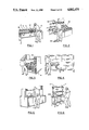
FIG. 21 is a somewhat diagrammatic side elevational view of an optical key for association with the scanner box of FIG. 14A;
FIG. 22 is a somewhat diagrammatic horizontal sectional view taken generally along the line XXII--XXII of FIG. 21;
FIG. 23 is a somewhat diagrammatic end view of the key configuration of FIG. 21;
FIG. 24 is a diagrammatic view illustrating a key receptacle for association with the scanner box of FIG. 14A and for receiving the key configuration of FIGS. 21, 22 and 23;
FIG. 25 is a diagrammatic longitudinal sectional view showing one-half of the key receptacle of FIG. 24 associated with a faceplate for mounting of the key receptacle in a wall of the scanner box;
FIG. 26 is a diagrammatic front elevational view of a kitchen printer cutoff mechanism for utilization in a cook station such as shown in FIG. 2 and may serve as a remote data presentation means;
FIG. 27 is a diagrammatic top plan view of the cutter mechanism of FIG. 26;
FIG. 28 is a diagrammatic left side elevational view of the cutter mechanism;
FIG. 28A shows a detail of the cutter blade in end elevation;
FIGS. 29A and 29B show power supply circuitry for the cutter mechanism of FIGS. 26, 27, 28 and 28A, and associated components, FIG. 29B being a continuation of FIG. 29A to the right;
FIGS. 30A through 30D show a control circuit for the printer including the cutter mechanism of FIGS. 27 et seq. and which receives power from the power supply of FIGS. 29A and 29B, and supplies control signals to the cutter bar circuitry of FIGS. 29A and 29B, FIG. 30B being a continuation of FIG. 30A to the right, FIG. 30C being a continuation of FIG. 30B to the right, FIG. 30D being a continuation of FIG. 30C in a downward direction, FIG. 30E showing a capacitor associated with the plus five volt supply; and FIG. 31 is a plan view of an overlay sheet for a keyboard subassembly which may be substituted for the keyboard subassembly of FIGS. 10, 11 and 12, so as to represent certain of the entry locations of the keyboard by means of icon-type pictorial images, as has been disclosed in detail in an application for patent of George E. Hanson, U.S. Ser. No. 049,778 filed May 12, 1987, which disclosure is hereby incorporated herein by reference; and
FIG. 32 is a diagrammatic plan view illustrating a portion of a paper web being fed from the cutoff mechanism of FIG. 26 when the cutter bar is modified to have increased length and a central notch.
DETAILED DESCRIPTION
FIGS. 1 through 6 illustrate various order processing stations in a system for delivering freshly prepared food such as pizza to the homes of individual customers. In a preferred conception, FIG. 1 may be taken as illustrating the conversion of an existing order entry station to one for practicing an initial type of embodiment in accordance with the present invention.
In a manual type of order station where the product is to be delivered to the customer's home, an employee 10 receives a phone order for the product e.g., via a telephone set 11, and manually fills out an order slip with the customer's address and particulars concerning the order. The handwritten order slip may then be manually transported to a cook station such as indicated in FIG. 2. If as an option the customer may pick up an order and pay for it in cash, the order entry station may also have a point of sale terminal 12 with a cash drawer 14. In a busy period of the day, additional employees may answer further telephones such as indicated at 16 through 18, (the point of sale terminal being located at a different work station for example).
In a preferred embodiment according to the present invention, the conventional point of sale terminal 12 is replaced by one or more microterminals, preferably with a microterminal associated at the right-hand side of a telephone set for a right-hand operator, and at the left side for a left-handed person. (A preferred microterminal configuration is shown in FIGS. 10, 11, and 12). The or each microterminal is then coupled via data transmission means such as indicated at 20 in FIG. 1 to stations such as that indicated in FIG. 2, each provided with suitable remote data presentation means such as a printer, or a monitor 22 as actually shown at cook station 24 in FIG. 2.
In an embodiment which avoids the need for employees to enter customer addresses via the microterminal keyboard, the order entry employee may key-in only the customer's telephone number and order. If it is a repeat customer, for example, the customer's address may have been stored in the system by a specially trained person based on an earlier hand-entered order. In this case, the system will automatically display the stored address at the microterminal screen in response to entry of the customer telephone number, and this address may be verified during the taking of the current telephone order. (For the case of a new customer or a new address, the address may be transmitted by the customer with the use of a push button telephone set directly to the system and be orally verified based on its on-line display at the microterminal, or the customer's voice statement of the address may be digitally recorded directly by the system e.g. for transcription by the delivery person at a check-out station such as shown in FIG. 6.)
Entry of an order for home delivery on the microterminal of FIGS. 10, 11, and 12 may produce a printed bar code label 30 such as indicated in FIG. 7. The bar code label 30 may have zones 31-40 for receiving order data. A bar code at zone 40 may represent an order number (such as 3465) assigned to the order by the system. In an initial implementation, an individual bar code label may be printed out by a bar code printer 42 at the order entry station for each order, and then other data may be entered by hand directly on the label. In a more advanced implementation, some or all of the data may be machine printed on the label at the respective zones 31-39 by the system. For example, the telephone number is preferably entered on the microterminal in even an initial implementation of the system, and would be readily machine printed at zone 37. The order data at 31, 33 and 34 is also coded into the system and readily machine printed. In a manual system the customer may be asked to describe his location, or an experienced person may enter geographical data other than address at zone 32 (e.g. a directional indication "N.E." northeast, and/or a grid indication "I-8" representing a sector defined in orthogonal coordinates with letters A, B, C, . . . , I, J, K, . . . designating geographical regions along one axis and with numerals 1, 2, 3, . . . , 8, 9, 10 . . . identifying geographical regions by means of the other axis.) The system may include a real time clock and enter the time of the order at 38. The total cost may be entered at 39. For a cash payment, region 41 may indicate if payment is to be made by a larger denomination bill (e.g. a twenty dollar bill). If payment is by credit, space 41 may indicate system approval for the amount of the order.
In a later phase of implementation of the system, all of the data for zones 32 and 35, 36 and 37 may be stored in the system for prior customers so that a complete label may be readily printed out at a bar code printer 50 at a remote station such as shown in FIG. 3, e.g. a box makeup station for the case of a pizza home delivery system. In an intermediate phase, label segments may be printed out on a web type backing strip at printer 42, FIG. 1, and may be periodically picked up by an employee from the station of FIG. 3, for example.
For new customers, the order entry employees may themselves enter a new address into the system via the microterminal keyboard. The system may be programmed to automatically enter desired further geographical data e.g. at zone 32, FIG. 7. In some cases, a special computerized system (e.g. a speech recognition system) may be assigned by the order entry employees to take address information from the customer (if acceptable to the customer), the order entry employee then returning to the telephone line to confirm the address as entered into the system. As an alternative, actual voice instructions from the customer could be digitally recorded and transmitted to a hand held data unit of the particular delivery person assigned to deliver the order. Such instructions could then be stored for future recall in the case of a repeat order from the same phone number. The recorded instructions could be replayed to the customer during receipt of a new order, for confirmation. Under certain circumstances, the customer telephone number could be transmitted to a driver's data unit by the data transmission system and could be available to effect automatic dialing of the customer from the delivery vehicle when desirable. For faster service, stations such as shown in FIGS. 3, 4 and 5 could be located in a delivery vehicle, the data transmission means such as 20 providing a radio coupling to a readout means such as printer 50. Such a system could be programmed to determine when a delivery vehicle should return to a central location e.g. as represented at FIG. 2, and the optimum sequence for beginning the baking of each order, and the actual delivery sequence for given orders.
As an example of an embodiment involving a larger operation, the order entry station of FIG. 1 may be centralized with a single telephone number serving a wide geographical area such as a city and suburbs. The geographical zones could then be numerically designated as at 60 in FIG. 8, ("370-005" e.g. representing a store number five of an owner or manager designated by number 370), each order being transmitted to a particular bake shop location such as represented at FIGS. 2 through 6 of a geographically dispersed group of such shop locations, or some of all of the orders being transmitted to mobile vehicles containing equipment such as indicated in FIGS. 2 through 6.
Referring to a cook station such as shown in FIG. 2, each order from the station of FIG. 1 may be stored in the system ready for display at readout means such as monitor 22, FIG. 2. When the cook completes a given order shown on monitor 22, the switch means or "bump bar" such as 62 is actuated e.g. by foot for signalling the system to display the next order; or a voice actuated switch may shift the display to the next order in response to a spoken command.
As shown at 64 in FIG. 8, the order may be displayed in an abbreviated format (e.g. "16" signifying a sixteen-inch diameter pizza, "B" signifying a "beef" type of pizza "0" calling for "everything" on one-half of the pizza, and "H" and "J" indicating only ham and bacon toppings on the other half).
Where an order includes beverages at a region such as 66, FIG. 8 (or at zones 33, 34, FIG. 7), this part of the order can be filled by the delivery person who may be reminded in this respect at a check-out station 70, FIG. 6, e.g. via a voice synthesizer unit 71.
Such voice synthesizer units may be located at other stations as may be desired as a more elaborate system becomes justified, for example to warn when a particular order has not reached the check-out station 70 within a pre-programmed time interval from the time of entry of the order. One or more voice synthesizers such as that at 71 may periodically state the number of minutes a given overdue order has been in the shop.
The label segment of FIG. 7 or FIG. 8 may be adhesively backed so as to be strippable from a backing strip or web such as indicated at 80, FIG. 8. Each label segment is then applied to a suitable size box at a station such as indicated in FIG. 3.
The driver check-out station 70 may include an instant bar code reader e.g. at a fixed location 82 for reading the bar code representing the order identification number (e.g. number 2072, FIG. 8). With the order identified the driver may receive a voice reminder from unit 71 as to beverages to accompany the order, the amount of change required, and any digitally recorded message recorded during order entry.
In practice, it has been found important to identify the driver who takes each other for delivery. In a preferred system, the driver has a key secured to an expansion cord holder on his belt, and each key is of a unique coded configuration. As a further precaution, it is preferred that the driver enter a confirming personal identification code on a keyboard 84. Entry of the correct personal identification code may trigger a flash of the instant bar code reader at 82, and also confirm that the particular driver is on duty. Instead of a key, the driver may insert (and thereby couple with the system) a personal hand held data unit with the driver's personal identification number encoded therein, e.g. an intelligent card type unit fitting in a shirt pocket. Concerning a shirt pocket size intelligent data terminal unit with built-in bar code scanning and communications capabilities, see Dennis Alan Durbin, Raymond C. Lo, Gary A. Welsch and Steven J. Kelly application for patent "Intelligent Information Card Terminal System," U.S. Ser. No. 897,547 filed Aug. 15, 1986. Upon the driver entering the corresponding number at keyboard 84, the system could read the bar code label at 82 and load the driver's data unit with customer telephone number and any relevant digitally coded speech instructions such as delivery instructions, including customer address and directions to reach the address, and preferences such as delivery to a back door or the like. A slip similar to that shown in FIG. 9 may be printed in the delivery vehicle based on data in the driver data unit so as to be handed to the customer to show the amount due. Further customer location information may be input by the driver e.g. as a speech input to the hand held driver data unit at the time of delivery, for later uploading into the system e.g. when the driver deposits cash at the store. Such cash deposits may be entered into the store data system so that the system keeps track of cash accumulations by each driver and can advise each driver during check out via speech synthesizer unit 71 when a further deposit of accumulated cash is advisable.
Under some circumstances, the labels may include embedded magnetic material which will trigger an alarm when removed from the store, the check-out station 70 including means to electrically modify the state of the magnetic material when the order it assigned to a driver in the approved manner.
A preferred microterminal for the systems, as described herein, is described in an application for patent of George E. Hanson entitled "TELEPHONE ORDER ENTRY SYSTEM AND TERMINAL THEREFOR", U.S. Ser. No. 049,778 filed May 12, 1987. For the sake of further identification, it is noted that FIGS. 10, 11, 12 and 13A through 13E hereof correspond to FIGS. 1, 2, 3 and 4A through 4E of said application in the name of George E. Hanson. A description from said application is as follows:
Description of FIGS. 10, 11, 12 and 13A-13E
FIG. 10 illustrates a conventional telephone console 110 which may, for example, be a commercially available "Merlin" telephone including a hand set 111 and a speaker phone 112. A group of consoles such as 110 may be used to selectively answer calls on a group of incoming telephone lines, the respective lines being selectable by means of selector keys arranged in groups as indicated at 115 and 116 at FIG. 10. Various control keys are arranged in a group at 118 for effecting "hold", "transfer" and other functions. A conventional set of dialing keys is indicated at 120 and other control keys are indicated at 121. It will be observed that the front panel 122 of the console is disposed at a convenient angle, for example about twenty-two degrees to a horizontal support surface such as a table surface having a number of such consoles thereon.
Adjacent each telephone console 110, there is arranged an order entry terminal 130 constructed in accordance with the present invention and preferably mounted so that its keyboard 131 lies in a plane disposed at an acute angle to the supporting surface corresponding to the angle of front panel 122. By way of example, keyboard 131 preferably includes a complete set of alphabetical characters, together with various symbol characters at an upper region 132, includes a set of control keys at a left-hand region 133 and a set of numeric keys at a region 134. Preferably a cathode ray tube display is located beneath a viewing lens 140 so as to provide for a display of a number of lines of characters.
In a preferred embodiment, terminal housing 150 is formed of a U-shaped body part 151 with respective end caps 152 and 153. In a particularly preferred embodiment as shown in FIG. 11, the body part 151 is formed of an aluminum extrusion providing integral side walls 161 and 162 and a bottom wall 163. The side walls 161 and 162 are configured so as to provide opposing pairs of guide channels 171, 172; 173, 174; and 175, 176. A keyboard assembly diagrammatically indicated at 181 is slidably supported at its marginal regions in channels 171 and 172, while a display module indicated at 182 is slidably supported by means of guide bars 183 and 184 which fit into the respective channels 173 and 174. A terminal management controller board 185 is slidably supported in the channels 175, 176. Name plates identifying the manufacturer of the terminal may be provided at 187 and 188 at shallow external grooves in the sidewalls 161 and 162. In assembly of the terminal, the respective subassemblies 181, 182 and 185 are engaged in the respective sets of cooperating channels and moved there along into the desired positions, whereupon the endcaps 152 and 153 may be applied so as to retain the parts in a desired fixed relationship.
Further preferred features of the illustrated embodiment are shown in FIG. 12 which is a somewhat diagrammatic longitudinal sectional view. As seen in FIG. 12, mounting blocks such as 191 are secured to the bottom wall 163 of the housing 150 and are provided with receiving apertures such as 192 for receiving in turned ends such as 193 of a mounting base 194 for the terminal. In the illustrated embodiment the base 194 is formed by a cylindrical cold rolled steel wire having a diameter of 0.250 inch and having a nickel plate finish. The wire is bent into a generally rectangular configuration so as to provide side pieces such as indicated at 195, FIG. 12, and 196, FIG. 10, with a transversely extending connecting part 97 having a protective covering 198 of suitable frictional material, for example neoprene tubing.
The mounting blocks such as 191 are provided with mounting surfaces such as 191A secured in flatwise engagement with the undersurface of a bottom wall 163 of the housing. The mounting blocks 191 are provided with first recesses 191B with axes generally parallel to the mounting face 191A, and second recesses 191C with axes disposed at a desired inclined angle such as twenty-two degrees. In FIG. 12, the mounting base 194 is shown locked in engagement with recesses such as 191C so that the terminal 150 is disposed at a desired inclined relationship to a flat supporting surface such as indicated at 201. For purposes of shipping and the like, the base 194 may be shifted from engagement with the recess 191C to engagement with the recess 191B so as to provide a more compact overall configuration for shipping or the like. A protrusion is indicated at 191D between the recesses 191B and 191C which serves to retain the base 193 in the respective recess into which it is adjusted. Each mounting block such as 191 is relieved at a region such as indicated at 191E to enable the respective in turned ends such as 193 to be inserted into the respective mounting blocks 191 prior to the mounting blocks being secured to the housing 150.
In the embodiment illustrated in FIG. 12, the keyboard assembly 181 includes a printed circuit board 209 supporting an array of silicone rubber actuators 210, an aluminum plate 211 with an array of apertures for receiving the respective actuators, and a membrane overlay 212 for identifying the respective keys. As shown in FIG. 12, the aluminum plate 211 contains a relatively larger aperture 215 at its forward end which is aligned with the viewing means such as a window means 140. The printed circuit board 209 may be secured at the proper spacing relative to the aluminum plate 211 by means of tapped holes such as indicated at 211A receiving screws such as indicated at 216.
In a preferred embodiment components 209, 211, 212 and 140 form a preassembled unit which is simply inserted into the receiving guide channels and moves there along to the desired position. A ribbon cable is indicated at 219 which plugs into an array of receiving holes at the underside of printed circuit board 209. Keyboard encoding is partially accomplished by the positioning of the traces on the circuit board 209 below the respective columns of keys. The keyboard is scanned and each key has its own row-column position to identify the character associated therewith.
As indicated in FIG. 12, the display module 182 may comprise a flat cathode ray tube 220 having a luminescent screen 221 disposed at an angle so as to be readily viewed through window means 140. A ribbon cable 222 connects a receptacle 223, FIG. 11, of the display module 182 with the terminal board 185. The ribbon cables such as 219 and 222 are provided with connectors such as 228 and 229 so that the cables can be detached from the keyboard unit 181 and the display module 182 and these units removed via their guide channels. In the preferred embodiment, only one cable connects the order entry terminal to external power and data communication lines.
In one particularly advantageous embodiment, the overall size of the terminal 130 is 4.5 inches by 2.5 inches by 9.25 inches. The wire base 194 has side parts 195 and 196 with a length of 7.0 inches, a connecting part 197 with a length of 4.5 inches, and in turned free end parts such as 193 with a length of 1.0 inch. In the keyboard assembly 181, the aluminum plate 211 had an overall length of 8.85 inches, a width of 4.40 inches, and a thickness of 0.062 inch. The aluminum plate had a rectangular aperture 215 with a height of 2.95 inches and a width of 3.50 inches for alignment with the window means 140. The overall thickness of the keyboard subassembly was 0.222 inches, the cooperating guide channels 171 and 172, FIG. 11, having a height dimension of 0.230 inch. In one example, the dimensions of the display module 182 were width, 104 millimeters; height, 204 millimeters; and thickness, 41 millimeters. The effective screen area is defined by a width of 81 millimeters, and a height of 59 millimeters, to provide a diagonal measurement of about 101 millimeters (about four inches). The guide bars 183 and 184 were provided with a height dimension of 1.15 inch, and a length generally of eight inches. The cooperating channels 173 and 174 had a corresponding height dimension of 1.15 inch and a depth of about 0.075 inch. The terminal board 185 had a width of 4.4 inches and a length of 9.1 inches. The cooperating guide channels 175 and 176 had a height dimension of 0.062 inch. The circuitry of the processor board 185 controlled the display tube 220 and provided interface to the keyboard. All of the video signals may be generated on the terminal board 185, as indicated in the accompanying FIGS. 13A-13E.
Exemplary control codes, escape codes and switch positions for an exemplary terminal configuration are shown on the following pages. The switch positions refer to switches SWI, SW2 and SW3, FIG. 13A, as indicated parenthetically in the following tabulation.
______________________________________                                    
Micro Terminal Control Codes                                              
CTL @   Switches terminal to local mode                                   
CTL F   Changes the display Baud rate                                     
        Increments to next higher rate for each "CTL F"                   
        sequence                                                          
Baud Rate Table                                                           
Terminal Code         Baud Rate                                           
00                   110                                                  
01                   134.5                                                
02                   150                                                  
03                   300                                                  
04                   600                                                  
05                   1200                                                 
06                   1800                                                 
07       Switch Setting                                                   
                     2400                                                 
08                   3600                                                 
09                   4800                                                 
10                   7200                                                 
11                   9600                                                 
12                   19.2 KB                                              
13                   19.2 KB                                              
14                   19.2 KB                                              
15                   4800                                                 
CTL G  Rings the bell                                                     
CTL H  Destructive backspace with wrap around                             
CTL I  Tab function - standard tab spacing is for 8                       
       characters Screen scrolling occurs at the bottom                   
       of the page                                                        
CTL J  Line feed function                                                 
CTL K  Vertical tab with scroll blanking the intervening                  
       lines                                                              
CTL L  Clears the screen and homes the cursor                             
CTL M  Carriage return character                                          
CTL N  Non-destructive vertical cursor movement with top                  
       to bottom scrolling                                                
CTL O  Non-destructive downward cursor movement with                      
       bottom to top scroll                                               
CTL P  Non-destructive left cursor movement with                          
       wrap around moving up a line on wrap                               
CTL Q  Non-destructive right to left cursor movement                      
       with wrap around moving down a line on wrap.                       
CTL R  Moves cursor to home                                               
CTL S  Generates a break signal                                           
CTL T  (14H) Line graphic symbol +                                        
CTL U  (15H) Line graphic symbol <                                        
CTL V  (16H) Line graphic symbol >                                        
CTL W  (17H) Line graphic symbol -                                        
CTL X  (18H) Line graphic symbol                                          
CTL Y  (19H) Line graphic symbol [                                        
CTL Z  (1AH) Line graphic symbol ]                                        
 ##STR1##                                                                 
        (1CH) Line graphic symbol                                         
CTL ]  (1DH) Line graphic symbol                                          
CTL    (1EH) Line graphic symbol                                          
CTL -  (1FH) Line graphic symbol                                          
Note: For graphic symbol control characters, attribute bit                
7 must be set to zero                                                     
Micro Terminal Escape Sequences                                           
Note: The escape key CHR$(27) is struck or transmitted                    
before the upper case character identifying the                           
function                                                                  
<ESC> A  Auxiliary port control (not implemented on                       
         microterminal)                                                   
<ESC> B  Display microterminal Uart configuration switch                  
         settings and Baud rate                                           
<ESC>  C Enter control mode and show all "non-displayable"                
         ascit characters                                                 
<ESC> D  Toggles the microterminal online or local                        
<ESC> E  Toggles the microterminal from FDX to HDX and                    
         back                                                             
<ESC> F  Turns control mode off                                           
<ESC> G  Flips status line to normal video and turns on                   
         the graphics attribute bit                                       
<ESC> H  Turns off the graphics attribute bit                             
<ESC> IV Set attributes to specified sequence "V". All                    
         subsequent characters retain this attribute                      
         setting until changed by another <ESC> IV                        
         sequence is entered                                              
Attribute Bit       Attribute                                             
#7                  Graphics                                              
#6                  Blank                                                 
#5                  Underline                                             
#4                  Double width                                          
#3                  Double height                                         
#2                  Blink                                                 
#1                  Half intensity                                        
#0                  Reverse video                                         
Note: A logic 0 value in a bit position enables an                        
attribute                                                                 
<ESC> K   Enables or disables the keyboard                                
<ESC> L   Light pen control (not implemented on the                       
          microterminal)                                                  
<ESC> Mxy Dynamic cursor control - X is the column                        
          parameter and is valid from 0 to 79                             
          Y is the line parameter and is valid from 0 to 23               
          X and Y values increment up from the ASCII Blank                
          character (20)                                                  
          The command:                                                    
          <ESC> M (25 Hex), (26 Hex) moves the cursor to                  
          position (5,6)                                                  
<ESC> P   Dumps screen data to the auxiliary port - (not                  
          implemented on the micro terminal)                              
<ESC> Q   Reruns self-test                                                
<ESC> R   Causes the contents of the current line from left               
          margin to be sent to the host character by                      
          character                                                       
<ESC> S   Causes screen contents from the home position                   
          to the current cursor position to be sent to the                
          host                                                            
<ESC> T   Erases the current line from the cursor to the                  
          right margin                                                    
<ESC> W   Erases switch information and Baud rate from                    
          the status line                                                 
<ESC> Y   Erases entire screen from the cursor location to                
          the end of the screen including the current                     
          cursor location                                                 
Micro-Terminal Switch Positions (FIG. 13A)                                
SW 1 Switch Position                                                      
             Function           Default                                   
#1           On for 50 HZ       Off                                       
             Off for 60 HZ                                                
#2           Loop mode          Off                                       
             On connects TXD + RXD                                        
             Off disconnects TXD + RXD                                    
#3           External test flag Off                                       
             On enabled                                                   
             Off disabled                                                 
Disabled if self test is not selected                                     
#4 + #5      Cursor select                                                
           SW5  SW4    Cursor                                             
           on   on     solid underline                                    
           on   off    solid block                                        
           off  on     blinking underline                                 
           off  off    blinking block                                     
                           SW #4    Off                                   
                           SW #5    Off                                   
#6           Reverse video          Off                                   
             On - enabled                                                 
             Off - disabled                                               
#7           External attributes                                          
                                On                                        
             On - enabled                                                 
             Off - disabled                                               
#8           Power on and reset self test                                 
                                On                                        
             On - enabled                                                 
             Off - disabled                                               
Micro Terminal Switch Positions (FIG. 13A)                                
SW #2 Position                                                            
           Function             Default                                   
#1         On - CRLF            Off                                       
           Off - CR                                                       
#2         Keyboard             On                                        
           On - scanned                                                   
           Off - encoded                                                  
#3         Local/on line        Off                                       
           On - local                                                     
           Off - on line                                                  
#4         FDX/HDX              On                                        
           On - FDX                                                       
           Off - HDX                                                      
#5         Slow                 On                                        
           On - transmit slow                                             
           Off - Recv slow                                                
Effectively disabled by #6 + #7                                           
#6                              Off                                       
           Split Baud rate                                                
#7                              Off                                       
         SW6  SW7    Divisor                                              
         on   on     32                                                   
         on   off    16                                                   
         off  on     4                                                    
         off  off    7                                                    
#8         Word length          Off                                       
           On - 7 bit                                                     
           Off - 8 bit                                                    
Micro Terminal Switch Positions (FIG. 13A)                                
SW #3 Position  Function     Default                                      
#1, #2, #3, #4  Band Rate                                                 
             SW1  SW2    SW3    SW4  Baud Rate                            
             on   on     on     on   110                                  
             on   on     on     off  134.5                                
             on   on     off    on   150                                  
             on   on     off    off  300                                  
             on   off    on     on   600                                  
             on   off    on     off  1200                                 
             on   off    off    on   1800                                 
             on   off    off    off  2400                                 
             off  on     on     on   3600                                 
             off  on     on     off  4800                                 
             off  on     off    on   7200                                 
             off  on     off    off  9600                                 
             off  off    on     on   19.2 KB                              
             off  off    on     off  19.2 KB                              
             off  off    off    on   19.2 KB                              
             off  off    off    off  4800                                 
                  2400 Band    SW#1 on                                    
off                            SW#2                                       
off                            SW#3                                       
off                            SW#4                                       
          #5 + #6 Parity Select                                           
                SW5  SW6                                                  
                off  off    space if enabled                              
                off  on     mark if enabled                               
                on   off    even if enabled                               
                on   on     odd if enabled                                
                           SW#5 on                                        
off                        SW#6                                           
          #7     Parity enable                                            
                 On - No parity                                           
                 Off - Parity enabled                                     
                               SW#7 on                                    
          #8     Stop bits                                                
                 On - two stop bits                                       
                 Off - one stopbit                                        
Characteristics of the Micro Terminal                                     
1.  Current prototype boards were loaded with the switches                
    backwards - the three switch position arrangements                    
    will be inverted on Version II (switch position #8                    
    will become #1 and so forth)                                          
2.  Graphics control characters are misinterpreted by the                 
    micro terminal board above 2400 Baud. This could be                   
    cables or software not operating properly and has yet                 
    to be repaired.                                                       
3.  When double wide characters are sent to the screen,                   
    the attribute must be properly set and the characters                 
    must be sent twice (Double becomes Ddoouubbllee) The                  
    second half of the character is accessed during the                   
    second character time. Likewise with double height                    
    characters, each line should be sent twice. It                        
    naturally leads that for a double wide, double high                   
    character two lines must be sent and each one must use                
    doublet characters.                                                   
The function and exemplary parameters for the                             
components of FIGS. 13A-13E are tabulated as follows.                     
Functions and Exemplary Parameters for the                                
Components of the Circuit of FIGS. 13A-13E.                               
FIG. 13A                                                                  
U1, U2, U3 Terminal Configuration Controller, e.g.                        
           type 74HC245                                                   
U4         Attribute RAM, e.g. type 6264                                  
U5         Character RAM, e.g. type 6264                                  
FIG. 13B                                                                  
U6, U7     Data Latch, e.g. 74HC573                                       
U8         Decoder, e.g. 74HC138                                          
U9, U10    Keyboard Scan, e.g. 74HC240                                    
J4         Keyboard connector                                             
FIG. 13C                                                                  
U11        Terminal Processor, e.g. NS405                                 
SW4        Reset switch                                                   
J5         Separated Video Output Connector                               
FIG. 13D                                                                  
U12        Data Latch, e.g. 74HC574                                       
U13, U14   Data Latch, e.g. 74HC573                                       
U15        Composite Video Generation, e.g.                               
74HC86U16  Terminal Program Storage, e.g. 2764                            
U17        Keyboard Scan, e.g. 74HC154                                    
U18        Beeper Control, e.g. 74HC123                                   
FIG. 13E                                                                  
U19        e.g. LM555                                                     
U20        Parallel Keyboard Decoder, e.g. 74HC244                        
U21, U22   RS232 Interface, e.g. MAX 232                                  
J1         Connector for cathode ray tube (82, FIG. 3)                    
R18        Contrast Control, e.g. zero to 100 ohms                        
R17        Brightness control, e.g. zero to fifty                         
           kilohmns                                                       
J2         Parallel keyboard connector                                    
J6         RS232 D-Sub Connector                                          
______________________________________                                    
In a prototype electric circuit bypass capacitors (designated C1 to C25, but not shown in FIGS. 13A-13E) were connected between the plus five volt supply line (+5 V) and ground, and had values of 0.1 microfarad except for two (C24 and C25) which were each rated at one hundred microfarads and six volts (6 V). In order to deal with noise problems, the pull-up potential of the Data Bus was increased so as to be nearer to the supply voltage, and additional decoupling capacitors were added. It is planned to use conductors of larger cross section for power and ground, and the power to the cathode ray tube 220, FIG. 12, will be the unregulated input voltage at line 240, FIG. 13E. An on-board DC to DC converter will be used in the CRT module 182. This improves system efficiency and distributes the internal heat dissipation. Basically, the modifications will improve the reliability of the terminal while retaining the advantages of the original configuration.
It is contemplated that a cathode ray tube with a green screen phosphor may enhance readability of the microterminal display. Anti-reflective coatings are being considered for the window means 140.
An optional "iconized" keyboard, FIG. 31, is designed to function in the same fashion as the elastomeric keyboard but with an additional fourteen keys. The technology of this keyboard is significantly different from the elastomeric unit. It is considered that both keyboards have their own market and as such the "iconized" style of keyboard will work well in food service installations but the elastomer unit is more appropriate for the more conventional computer terminal application. The emphasis here is upon the flexibility of this unit. A keyboard change will only affect the "look" of the unit, not its functions. Additionally, the circuit board is being redesigned to allow the use of custom character sets. This involves the addition of three more IC's. Since the configuration is fairly well determined, ten components will be removed from the existing board and will be replaced by one. The components to be removed are three dip switches, three buffers (74HC245), three resistor packs and one 74HC138 decoder chip. Reliability and performance should be enhanced by this reduction in component count.
Description of the Specific Embodiment of FIGS. 14A and 14B
FIGS. 14A and 14B illustrate a specific implementation of a pizza home delivery system falling within the scope of the present invention. The illustrated system includes a manager station 14-10 and a driver check-out station 14-11, FIG. 14A, and a make station 14-12 and an order entry station 14-13, FIG. 14B.
The manager station 14-10 may include conventional data processing equipment such as a personal computer 14-20 with a keyboard 14-21, a monitor 14-22 and a line printer 14-23. This equipment may generate daily reports including individual driver cash reconciliation reports, based on the data generated at the driver station 14-11 as herein described. Cash deposits by the drivers may be entered into the system via keyboard 14-21, for example.
A portable hand held data unit 14-26 may have a receptacle at the manager station such that when the unit is inserted into such receptacle, it is placed on line with the total system. Such a receptacle is commonly used with a hand held data unit model 121 of the Norand Corporation of Cedar Rapids, Iowa. Rechargeable batteries of the unit 14-26 may be recharged from power supply 14-27 while the unit is associated with its receptacle. The unit 14-26 may represent means for transporting system data to a manager's residence, for example, or to a delivery vehicle, for example, as well as means for collecing inventory and/or pricing data for input to the system.
Scanner box 14-28 at the manager station may be identical to scanner box 14-30 at the driver station 14-11, so that these units are fully modular and interchangeable. An instant bar code reader such as 14-31 may be plugged into either scanner box and may be used to instantaneously read an individual bar code assigned to each driver, as well as to read the bar codes of labels such as shown in FIGS. 7 and 8.
As an example, the manager station may have an automatic cash depository similar to an automatic teller machine. The driver may deposit cash with the system by presenting a badge or card with his identifying bar code e.g. at a receiving slot associated with a fixed scanner, or to hand held reader 14-31; or an individually coded key such as indicated at 14-35 may be inserted in a key receiving aperture of scanner box 14-28 as indicated in FIG. 14A. The driver may also manually enter his personal identification code on a keyboard 14-36. If there is a match of identification codes, the driver may be permitted to enter the amount of his cash deposit for example via a keyboard coupled with the system, in a manner similar to operation of automatic teller machines. A similar procedure using a key such as 14-35 and the keyboard 14-36 may be used for maintaining a record in the system of the hours worked by each employee.
The scanner box 14-30 of the driver check-out station 14-11 may be mounted generally as shown in FIG. 6 and arranged to receive individual driver's identification keys as indicated at 14-40. The hand held bar code reader 14-31 may be triggered manually by a button 14-41 to read a label on a box such as 251, FIG. 6, e.g. while the box is supported on a table surface such as 252. In the example of FIG. 14A, reader 14-31 may also be triggered manually by the button 14-41 to read a bar code on an employee badge or identification card as an alternative to the key identification means 14-40. An indicator light 14-42 may emit green light when a valid bar code is read, and may provide a red light signal to indicate the need for a repeated read operation.
Information on the construction of bar code readers is found in a pending application of Jonathan R. White, U.S. Ser. No. 905,779 filed Sept. 10, 1986, Attorney's Docket DN 5726, and in a pending application of Arvin D. Danielson and Dennis Alan Durbin, U.S. Ser. No. 894,689 filed Aug. 8, 1986. Reference is also made to a commercial product of Norand Corporation known as the 20/20 Instant Portable Bar Code Reader.
An exemplary interface circuit for the scanner boxes 14-28 and 14-30 may be similar to that shown in FIGS. 15A-15J.
The data communications means of the system of FIGS. 14A and 14B is illustrated as comprising a network controller 14-50 coupled with the other stations via a communications bus such as indicated at 14-51. Network controller 14-50 and identical network controllers 14-52 and 14-54 at the make station 14-12 and the order entry station 14-13 may be similar to those shown in a pending application of Arvin D. Danielson, Joseph J. Kubler, Dennis Alan Durbin, Micheal D. Morris and Keith K. Cargin, Jr., U.S. Ser. No. 907,496 filed Sept. 15, 1986, and in a pending application of Keith Cargin, Jr., George E. Hanson and Phillip Miller, U.S. Ser. No. 915, 023, filed Oct. 3, 1986.
A voice module 14-56 with its speaker 14-57 may be of conventional construction and a similar unit may be provided at other stations for example as indicated at 14-60 and 14-61 in FIG. 14B. These units may function as described with reference to voice synthesizer unit 71, FIG. 6.
FIG. 14B illustrates the case where a receipt printer 14-64 prints receipts such as indicated at 260, FIG. 9. In the specific embodiment of FIG. 14B, a bar code printer 270 is shown located at an order entry station in correspondence with bar code printer 42 of FIG. 1. The printer 270 may produce a bar code label such as described with reference to FIG. 7 or FIG. 8 which may be adhesively applied to an appropriate size box at the make station 14-12, for example, and scanned at the driver check-out station 14-11 as previously described.
An exemplary bar code printer is a modified Zebra thermal bar code printer.
Microterminals such as indicated at 14-71 and 14-72 may correspond with those shown in FIGS. 10, 11, 12 and 13A through 13E and may be associated with respective telephone consoles and operated as described herein.
The coupling of terminals within a store with other units e.g. at a manager station via a loop fiber optic network is described in U.S. Pat. Nos. 4,430,700 and 4,604,693 of Norand Corporation and is utilized in a commercial system of Norand Corporation known as the A Line Food Service Management System.
Summary of Operation of FIGS. 14A and 14B
In operation of the specific exemplary embodiment of FIGS. 14A and 14B, a telephone order is processed at station 14-13 by entering the telephone number of the incoming call into the system e.g. automatically or via a keyboard such as indicated at 271. The telephone number may serve to retrieve the caller's last known address for display at 272, where it can be verified. In an initial type of system, customer addresses may be entered manually as at 36, FIG. 7, on a bar code label supplied by printer 270, as indicated at 274, FIG. 14B. Other desired data may be entered manually, for example as indicated at 31 through 35 and 37, 38 and 39, FIG. 7, or such data may also be mechanically imprinted by the system as represented in FIG. 8.
In an initial system, a person from make station 14-12 may periodically pick up completed labels and affix the same to appropriate packaging, e.g. generally as indicated in FIG. 3.
At the make station 14-12, each order may be read out on-line by means of the receipt printer 14-64 to produce duplicate receipt slips such as indicated at 260, FIG. 9. Such slips may be used in place of monitor 22, FIG. 2, to sequence the order preparation process. Thus, a receipt slip such as 260, FIG. 9, may accompany each pizza as it is being packaged (as indicated in FIG. 5) at the make station 14-12, and may accompany the packaged order as delivered to the driver station 14-11.
In the actual system of FIGS. 14A and 14B, the time of each order would be entered into the system, and voice synthesizer units 14-60, 14-61 and 14-56, 14-57 would be activated if a given order had not been checked out at scanner means 14-30, 14-31 within a time interval established in the system. In an actual operating system similar to that of FIGS. 14A and 14B, the voice synthesizer unit may repeat warning messages at a selected interval specifying the number of minutes an overdue order has been in the system. Other messages may be given exclusively at the driver station, for example a reminder concerning beverages for an order being checked out, or a message to a specific driver identified at scanner means 14-30, 14-31, suggesting that a deposit of accumulated cash would be advisable.
Description of FIGS. 15A through 15J
The exemplary scanner interface circuit of FIG. 15A et seq. is most closely related to the embodiment of FIG. 6. In this case, a coded key sensor of FIG. 6 is coupled to connector 15-10, FIG. 15E, and the instant scanner unit at 82 is coupled to a connector 15-12, FIG. 15A, while keyboard 84, FIG. 6, is coupled at 15-15, FIG. 15D.
Exemplary components in FIG. 15A et seq. may be as follows:
______________________________________                                    
                           Exemplary                                      
Component Description      Type Designation                               
______________________________________                                    
J2        RS-232 Interface DE-9S*                                         
J3        Instant Bar Code DA-155*                                        
          Reader Interface                                                
J4        Key lock input   10P-HDR                                        
U2        RS-232/TTL       LT1080                                         
          converter                                                       
Y1        Crystal (5.5295                                                 
          Megahertz)                                                      
U7        Eight-Bit Microcomputer                                         
                           8031                                           
U6        Octal Transparent Latch                                         
                           74HC573                                        
          Three-State                                                     
U5        EPROM chip       27256                                          
U9A, U9B  Two to Four Decoders                                            
                           74HC139                                        
U11       Binary Counter   74HC4020                                       
U12       Binary Counter   74HC4040                                       
U13A, U13B                                                                
          Comparator       LM393                                          
UI        Octal D-Type Flip-Flop                                          
                           74HC574                                        
          Positive Edge-Trig-                                             
          gered Three-State                                               
U3, U10   Octal Transparent                                               
                           74HC573                                        
          Latch, Three-State                                              
J1        Keyboard Interface                                              
                           Header-                                        
                           S15P**                                         
B1        Piezo transducer (beeper)                                       
                           QMB111                                         
______________________________________                                    
 *"S" stands for socket or receptacle type of connector.                  
 **"P" stands for pin type of connector.                                  
The following shows an exemplary program sequence for the driver station 14-11, FIG. 14A, or 70, FIG. 6:
______________________________________                                    
(1)   Input from scanner box e.g. 14-30, FIG. 14A:                        
Employee Number and Order Number of box such                              
as 251, FIG. 6, from bar code label of FIG.                               
7 or FIG. 8 on the box.                                                   
(2)   Get order from order storage means 290, FIG. 14A.                   
(2A)        Does order have more than one box?                            
(2A1)       If yes, speak: "* ------ pizza's"                             
            then go to (1) for order number of                            
            other box or boxes.                                           
(2A2)       If no, continue at (2B).                                      
(2B)        Does order contain beverages?                                 
(2B1)       If yes, speak: "This order contains                           
            beverage" (e.g. via synthesizer unit                          
            14-56, 14-57, FIG. 14A, or 71, FIG. 6).                       
(2C)        Is order for cash payment only?                               
(2C1)       If yes, speak: "This order is cash                            
            only".                                                        
(2D)        Compute and speak: "** ------ minutes                         
            out the door".                                                
(2E)        Driver cash too high?                                         
(2E1)       If yes, speak "Driver please make a                           
            drop (deposit)".                                              
(3)   Update files.                                                       
______________________________________                                    
 *A number is to be spoken here according to the number of boxes needed fo
 the order.                                                               
 **A number is to be spoken here according to the number of minutes betwee
 the original entry of the order and scanning of the box or boxes for the 
 order at the checkout station.                                           
An exemplary directory of speech synthesizer elements at respective directory location numbers is as follows:
______________________________________                                    
VERSION .0.                                                               
DIRECTORY # WORD OR PHRASE                                                
______________________________________                                    
0           BETWEEN SENTENCE PAUSE                                        
1           0                                                             
2           1                                                             
3           2                                                             
4           3                                                             
5           4                                                             
6           5                                                             
7           6                                                             
8           7                                                             
9           8                                                             
10          9                                                             
11          10                                                            
12          11                                                            
13          12                                                            
14          13                                                            
15          14                                                            
16          15                                                            
17          16                                                            
18          17                                                            
19          18                                                            
20          19                                                            
21          20                                                            
22          30                                                            
23          40                                                            
24          50                                                            
25          60                                                            
26          70                                                            
27          80                                                            
28          90                                                            
29          OF                                                            
30          THIS ORDER IS CASH ONLY                                       
31          PIZZA'S                                                       
32          DRIVER PLEASE MAKE A DROP                                     
33          MINUTES OUT THE DOOR                                          
34          THIS ORDER CONTAINS BEVERAGE                                  
35          INVALID ORDER NUMBER                                          
            THIS PIZZA IS IGNORED                                         
XON - XOFF                                                                
XON EVERY SEVERAL SECONDS, GUARANTEES                                     
32 OR MORE BYTES IN INPUT BUFFER                                          
______________________________________                                    
The following is an outline concerning the circuitry of FIGS. 15A-15J:
1.0 Scope:
This document describes the architecture of a CCD 20/20 scanner interface equipped with a Key Board, Key Lock (removable nonvolatile memory module), and an RS-232 communications link. This document includes a description of the memory mapped I/0, the RAM location and the I/0 port functions.
2.0 Scanner Unit Architecture:
The interface is an 8031 microcontroller base unit with 32K of program memory and 8K of data memory.
Port I/0 consists of an RS-232 two line type interface, a scanner interface that will service a 20/20 bar code reader or a wand, and a key lock type nonvolatile removable memory module.
Memory mapped I/0 is made up of a 12 key keypad matrix input/output, a buzzer, two LED output bits, an eight bit address switch, and a memory read location to reset a watchdog timer.
2.1.0 Interface memory map:
2.1.1 Memory Map Location:
______________________________________                                    
      (1) Program memory:                                                 
                      Starts at 0000 hex                                  
      (2) RAM memory: Starts at 0000 hex to 3FFF                          
hex                                                                       
      (3) Key Pad     4000   hex                                            
                      Write bits   0,1,2                                    
                        Read bits   0,1,2,3                                   
      (4) Buzzer      4000 hex Write bit 3                                
      (5) LEDs        4000 hex                                            
                      Green LED Write bit 4                               
                      Red LED Write bit 5                                 
      (6) Address Switch                                                  
                      8000 hex                                            
      (7) Watch-Dog   C000 hex                                            
                      The watchdog will reset the                         
                      CPU in no less than 1 sec.                          
                      and no longer than 2 sec.                           
______________________________________                                    
2.1.2 Memory Mapped I/0 Operation Definition:
Key Pad Operation:
______________________________________                                    
Key Pad Matrix Truth Table                                                
Key           Write bit    Read bit                                       
______________________________________                                    
1             0            2                                              
2             1            2                                              
3             2            2                                              
4             0            1                                              
5             1            1                                              
6             2            1                                              
7             0            0                                              
8             1            0                                              
9             2            0                                              
*             0            3                                              
0             1            3                                              
#             2            3                                              
______________________________________                                    
 Write bit low to column (bit 0 thru 2)                                   
 Read bit as a low true for row (bit 0 thru 3)                            
Buzzer operation:
Initialize bit to 0 when not in use
To operate, write bit 3 alternating from "1" to "0" at twice the desired frequency.
Example: for 2000 hertz tone, the period between writing a "1" to a "0" or "0" to a "1" would be 250 microseconds
LED Operation:
Green LED--write bit 4 Low to turn "ON" High to turn "OFF"
Red LED--write bit 5 Low to turn "ON" High to turn "OFF"
2.2.0 Interface I/0 Assignments:
2.2.1 Scanner interface signals:
______________________________________                                    
Signal  Name/type  Port #   Description                                   
______________________________________                                    
/PROX   Input      P3.2     Read Data (unit reading)                      
XOVR    Input      same     Wand scanner data input                       
TD      Output     P1.0     Commands to CCD 20/20                         
RTS     Output     PI.1     Clock to CCD 20/20                            
CTS     Input      P1.2     High if 20/20                                 
                            Low if wand                                   
SCNPWR  OUTPUT     P3.4     Digital type wand enable                      
                            active high.                                  
______________________________________                                    
2.2.2 RS-232 Interface:
______________________________________                                    
Signal    Name/type   Port #    Description                               
______________________________________                                    
RX        Input       P3.0      Received Data                             
TX        Output      P3.1      Transmit Data                             
______________________________________                                    
2.2.3 Keylock Interface:
______________________________________                                    
Signal   Name/type  Port #   Description                                  
______________________________________                                    
KYPWR/   Output     P1.3     Key module power                             
CS       Output     P1.4     Key module chip select                       
D1       Output     P1.5     Serial Data into key                         
SK       Output     P1.6     Serial Data Clock                            
DO       Input      P1.7     Serial Data from key                         
LOFO     Input      P3.3     Last-on-First-off                            
                             This signal goes high                        
                             after the key is all                         
                             connected and low before                     
                             the key disconnects.                         
______________________________________                                    
Description of FIGS. 16A-16H and 17A-17D
FIGS. 16A-16H and 17A-17D show exemplary circuitry for the voice modules 14-56, FIG. 14A, and 14-60, FIG. 14B. Exemplary components for this circuitry may be as follows:
______________________________________                                    
Speech Electronics, FIGS. 16A-16H                                         
Component     Description                                                 
______________________________________                                    
FIG. 16A                                                                  
16-J3         RS-232 D-Sub Connector                                      
16-U2         RS-232 Interface, e.g. MAX 232                              
FIG. 16B                                                                  
16U8, U9      Watchdog Counter, e.g.                                      
              74HC390                                                     
FIG. 16C                                                                  
16-Y1         Crystal 12.0000 MHZ                                         
16-U3         Microcontroller, e.g.                                       
              80C31                                                       
16-U4         e.g. 74HC573                                                
16-U6         Program Storage, e.g. 27C64                                 
FIG. 16D                                                                  
16-U17, U18   e.g. 74HC244                                                
16-U7         e.g. 74HC573                                                
16-J1         37 Pin D-Sub Connector                                      
FIG. 16E                                                                  
16-U10        e.g. 74HC193                                                
16-U11        Parallel to Serial                                          
              Shift Register, e.g.                                        
              74HC597                                                     
16-U12        Continuously Variable                                       
              Slope Modulator (CVSD)                                      
              chip, e.g. MC3418                                           
FIG. 16E                                                                  
16-U15        e.g. LTC1044                                                
FIG. 16F                                                                  
16-REG1       e.g. LM340T-5                                               
16-DS1        Red Light Emitting Diode                                    
              ("Power On" Indicator)                                      
FIG. 16G                                                                  
16-U13        Switched Capacitor                                          
              Filter Chip, e.g.                                           
              MF4-100                                                     
16-R4         Volume Adjust                                               
              Potentiometer, e.g.                                         
              zero to one                                                 
              hundred kilohms                                             
16-U14        Audio Power Amplifier                                       
              chip, e.g. LM386                                            
16-U2         RCA Phone Jack                                              
              (To Eight-Ohm Speaker)                                      
FIG. 16H                                                                  
C1-C18        Bypass Capacitors                                           
              e.g. 0.1 microfarad                                         
Read Only Memory Module, FIGS. 17A-17D                                    
FIG. 17A                                                                  
17-J1         37 Pin D-Sub Connector                                      
17-J2         20 Pin Connector                                            
              (for additional ROM)                                        
17-J3         20 Pin Connector                                            
              (for additional ROM)                                        
FIG. 17B                                                                  
17-U1, U8     EPROM e.g. 27C256                                           
FIG. 17C                                                                  
SEL1- SEL4      512K or 256K                                                
              EPROM Selectors                                             
17-U9         e.g. 74HC138                                                
17-U10        e.g. 74HC688                                                
SW1           PROM Size Select                                            
              (Six Pole DIP Switch,                                       
              Open = 256K EPROM)                                          
FIG. 17D                                                                  
C1-C10        Bypass Capacitors                                           
              e.g. 0.33 microfarad                                        
______________________________________                                    
The speech generator comprises the speech electronics of FIGS. 16A through 16H and the read only memory module of FIGS. 17A-17D. The speech electronics is contained in its own housing and connects to the host system (indicated in FIGS. 14A and 14B) via a nine pin connector 16-J3, FIG. 16A. The speech electronics module has a standard RCA phono jack 16-J2, FIG. 16G, to connect its audio output to an external speaker such as indicated at 14-57, FIG. 14A, or 14-61, FIG. 14B. The module also has a volume control, 16-R4, FIG. 16G, and a "power on" indicator 16-DS1, FIG. 16F. The speech module mates with the ROM module via a thirty-seven pin "D" connector 16-J1, FIG. 16D, at its top side. Together the two modules are mounted in a vertical position with the ROM module on top.
The ROM module contains the actual voice messages, stored in CMOS EPROMS indicated at 17-U1 through 17-U8, FIG. 17B. The module normally contains a single "main" board mounted in the center of its housing. The main board has provision for holding up to eight EPROM chips of either the 27C256 or 27C512 variety (jumper selectable). The speech electronics "reads" 30,000 bits per second from the ROM module, so a single 256K ROM chip can store 8.5 seconds of speech. As an example, a fully populated ROM module main board can contain sixty-eight seconds of speech if using 27C256 EPROM chips, and 136 seconds of speech if using 27C512 EPROM chips. The ROM module is designed to accept two additional "piggyback" EPROM boards, each with six EPROM chips. One board mounts on top of the main ROM board, while the other mounts beneath the main ROM board. A ROM module so equipped with 27C512 chips permits 5.7 minutes of continuous non-repetitive speech.
The ROM module receives its power through the thirty-seven pin "D" connector, 17-J1, FIG. 17A, as well as twenty-four bits of ROM addressing, from the speech electronics module. Eight bit parallel ROM data (via D0-D7) is fed back to the speech electronics module via the same connector.
The speech electronics module contains a microcontroller 16-U3, and RS-232 interface 16-U2, a "watchdog" circuit 16-U8, 16-U9, FIG. 16B, a continuously variable slope monitor chip 16-U12, an audio filter chip 16-U13, and a small audio power amplifier stage 16-U14.
Chip 16-U6 provides storage for the microcontroller program. The microcontroller provides ROM module addressing and receives the resultant byte of data from the ROM module. The speech data byte is output from the microcontroller to a parallel to serial shift register 16-U11, FIG. 6E. The shift register 16-U11 is clocked continuously by counter hardware 16-U10, providing a constant thirty kilobit per second data stream to the CVSD chip 16-U12, FIG. 16E. Chip 16-U12 converts the serial data stream to an analog signal (voice) which is then bandwidth-limited to three kilohertz by a switched capacitor filter chip 16-U13, FIG. 16G. The audio signal is amplified by audio power amplifier chip 16-U14 and output to the RCA phono jack 16-J2.
The CVSD chip 16-U12 is driven continuously, even during "no speech" times to prevent undersirable clicks at the beginning and end of messages. At the end of the last message, the microcontroller 16-U3 outputs a "quieting" pattern byte to the shift register 16-U11 to quiet the output of the CVSD chip 16-U12.
The speech electronics board uses a "watchdog" timer circuit 16-U8, 16-U9 to reset the microcontroller in case the program fails. The watchdog circuit must be pulsed by the microcontroller via line 1610, FIG. 16C and FIG. 16B, every twelve milliseconds or it will generate a reset pulse resetting the microcontroller.
The microcontroller 16-U3 communicates with the host system via an RS-232 port bus 1611, FIG. 16C, FIG. 16A, using X-on/X-off protocol. The microcontroller buffers up to thirty commands from the host system, and executes them sequentially. Commands from the host system consist of numbers, separated by spaces, and followed by a carriage return. Each number represents a message stored in the ROM module; see the table with the heading "VERSION .0. (application page 38). A phrase may consist of just one number (e.g. No. 30, No. 32, or No. 34), or a combination of numbers (e.g. No. 22 followed by No. 33) to form a complete sentence. The speech electronics module begins executing the first message upon receiving a carriage return. There is no real limit on the number of messages stored in ROM. The only limit is the ROM space needed to speak them all.
Messages are stored sequentially in the ROM address space. At the very "bottom" of ROM memory space is a library of all the messages. The library contains five bytes of information for each message stored in ROM. The first three bytes of each message description in the library define the absolute starting address of the message in ROM. The last two bytes define the length of the message (in bytes). The microcontroller 16-U3 locates each message to output by multiplying the message number, receive from the host system, by five so as to obtain the proper address offset in the message library. The microcontroller then retrieves the pertinent data from the library, then proceeds to the absolute ROM memory address and begins retrieving ROM speech data for that message a byte at a time. The counter hardware 16-U10 controlling the shift register 16-U11 and the CVSD chip 16-U12 also signals via line 1612, FIG. 16E, FIG. 16B to the microcontroller 16-U3 when a new byte of data is required by the shift register 16-U7. The speech message is supplied from the CVSD chip 16-U12 to the filter chip 16-U13 via line 1614, FIG. 16E, FIG. 16G. During quiet times the microcontroller ignores these requests for data so that the shift register continues to output its current byte of data repeatedly to the CVSD chip 16-U12. Of course, the data byte is the "quieting" byte needed to quiet the output of the CVSD chip.
DESCRIPTION OF FIGS. 18A-18I
FIGS. 18A-18I illustrate an exemplary speech editor system for receiving analog (voice) signals at jack 18-J2, FIG. 18G, and digitizing the signals for storage and processing. Exemplary components for the speech editor circuitry are as follows:
______________________________________                                    
Component       Description                                               
______________________________________                                    
FIG. 18A                                                                  
18-J1           RS-232 D-Sub Connector                                    
18-U4           RS-232 Interface                                          
                e.g. MAX232                                               
18-U6, U7       e.g. 74HC390                                              
FIG. 18B                                                                  
Y1              Crystal, 12.000 MHz                                       
18-U5           Microcontroller, e.g.                                     
                80C31                                                     
18-U3           e.g. 74HC573                                              
18-U2           e.g. 74HC138                                              
18-U12          Program storage                                           
18-U8, U9       RAM e.g. 6264                                             
FIG. 18C                                                                  
U10, U11        RAM, e.g. 6264                                            
FIG. 18D                                                                  
18-REG1         E.G. LM340T-5                                             
18-J4           Two-pin Mate and                                          
                Lock Connector                                            
FIG. 18E                                                                  
C-1-C21         Filter Capacitors,                                        
                e.g. 0.1 Microfarad                                       
FIG. 18G                                                                  
18-U16          E.G. 74HC193                                              
18-U18          Serial to Parallel                                        
                Shift Register, e.g.                                      
                74HC595                                                   
18-U19          Serial to Parallel                                        
                Shift Register, e.g.                                      
                74HC597                                                   
18-U21          Switched Capacitor                                        
                Filter Chip, e.g.                                         
                MF4-100                                                   
FIG. 18H                                                                  
18-U17          Continuously Variable                                     
                Slope Modulator                                           
                (CVSD), e.g. MC 3418                                      
18-U20          Switched Capacitor                                        
                Filter Chip, e.g.                                         
                MF4-100                                                   
18-J3           RCA Audio Jack                                            
FIG. 18I                                                                  
18-U14          e.g. LTC 1044                                             
______________________________________                                    
The editor circuitry of FIGS. 18A through 18I is controlled via an RS-232 input at 18-J1, FIG. 18A, and communicates with the host personal computer system using the X-on/X-off protocol. The program (known as "PHRED") running on the host personal computer prompts the user with a menu. The menu possibilities are:
(1) RECORD A PHASE
(2) PLAY BACK A PHRASE
(3) READ DIGITIZED PHRASE FROM PHRED ONTO DISK
(4) WRITE DIGITIZED PHRASES FROM DISK TO PHRED
(5) LIST PHRASES CURRENTLY ON DISK
(6) CHECK LINK WITH PHRED (checks RS-232 link)
The RAM storage 18-U8 through 18-U11 may provide only 8.5 seconds of speech, so that any message recorded or played back can be only 8.5 seconds long. If the message is to be longer, then it can be divided into several sections and played back on the "target" system with no perceptible pause between sections.
To record a phrase the user selects the appropriate menu and follows the prompts on the screen. The editor system accepts the user audio via input 18-J2, FIG. 18G, and amplifies the signal at 1810 to usable levels. The analog signal is passed through the band-limiting filter 18-U21 which limits the bandwidth to three kilohertz, and is then sent via line 1811, FIG. 18G, FIG. 18H, to the CVSD chip 18-U17. The CVSD chip digitizes the analog signal into a serial data stream at thirty kilobits per second. The serial data is supplied via line 1812, FIG. 18H, FIG. 18G, to the serial to parallel shift register 18-U18. The microcontroller 18-U5 is signaled by the counter hardware 18-U15 (via line 1814, FIG. 18G, FIG. 18H, of bus 1815, FIG. 18H, FIG. 18B,) that a byte of data is available for RAM storage, at the output port of shift register 18-U18. The byte of digitized voice data is placed in the next available RAM location and the RAM address counter 18-U2, 18-U3, FIG. 18B, is advanced to the next location. The procedure is repeated again and again until RAM space is used up or the user presses the space bar on the host computer keyboard, to stop recording.
Once a message is stored in the RAM memory 18-U9 through 18-U11, it can be played back in its entirety or in small sections, again menu selected by the user. A phrase can be dissected into its individual words or sounds and each stored as a new independent phrase. The editor plays back the selected phrase, or partial phrase, by reading sequential bytes of data from the RAM storage and outputting them one at a time to the parallel to serial shift register 8-U19, FIG. 18G. Counter hardware alerts the microcontroller that a new byte is needed by the shift register when the last byte has been shifted out. Actually the shift register 18-U19 is "double-buffered" meaning that it contains two byte storage locations. One is undergoing shifting while the other waits. This allows the processor 18-U5 more time to deliver another byte of data, a feature that facilitates programming. The shift register 18-U19 outputs the digital voice data via 1817, FIG. 18G, FIG. 18H, to the CVSD chip 18-U17 at thirty kilobits per second for conversion to analog form. A resultant analog signal from the chip 18-U17 is bandwidth-limited to three kilohertz at component 18-U20 and output to a buffer amplifier 1818, FIG. 18H. The buffer amplifier simply drives a pair of head phones so that the user can hear the results of his/her editing.
The audio signal is bandwidth-limited by component 18-U21, FIG. 18G, when recording to prevent "aliasing", a distortion that is caused by a signal changing too much between digitization sample periods. The bandwidth-limiting at the output of 18-U17, FIG. 18H, is needed to limit the high frequency content of the signal, and to strip off the digitization noise that occurs as a result of waveform reconstruction.
Once the user is satisfied with the edited phrase, he or she can transfer the data to the host system's mass storage device (e.g. a hard or floppy disk, or a system RAM disk) where it will be stored as a unique message.
A message, or group of messages, can be transferred from the host memory to EPROM devices such as 17-U1 through 17-U8, FIG. 17B, for use in the target speech generator device. As previously described, first the messages are collected and butted together (to save memory space), and a library formed defining each message's absolute starting address and length. This is done using the program "DOMFILE" which prompts the user for the names of the stored message phrases and links them together and creates the library. The library is linked first so it resides in the lowest target ROM addresses.
Description of FIGS. 19A-19F
FIGS. 19A through 19F show a circuit for the scanner box 14-28 or 14-30, FIG. 14A, which has been revised somewhat in comparison to the circuit of FIGS. 15A-15G. Exemplary components in FIG. 19A et seq. may be as follows:
______________________________________                                    
Component      Description                                                
______________________________________                                    
FIG. 19A                                                                  
19-J1          Nine Position Connector                                    
               for RS-232 Interface                                       
19-J2          Fifteen Position Connector                                 
               for Instant Bar Code                                       
               Reader Interface                                           
19-J3          Ten Pin Header for                                         
               Key Lock Input                                             
19-U1          RS-232/TTL Converter                                       
               e.g. LT1080                                                
19-Y1          Crystal (5.5295                                            
               megahertz)                                                 
19-U2          Microcomputer,                                             
               e.g. 8031                                                  
19-U7          e.g. DS1232                                                
FIG. 19B                                                                  
19-U3          e.g. 74HC573                                               
19-U4          e.g. 27C64                                                 
19-U11         e.g. 74HC574                                               
19-U5          e.g. 6264                                                  
19-U8          e.g. 74HC139                                               
FIG. 19C                                                                  
19-J4          Fifteen Position Header                                    
               for Keyboard Interface                                     
19-J7          Three Position Header                                      
               (See FIG. 19E)                                             
19-B1          Piezo Transducer (Beeper)                                  
               e.g. QMB111                                                
19-U6,         e.g. 74HC573                                               
19-U10                                                                    
19-J5          Sixteen Position Header                                    
               for LED Interface                                          
19-J6          Sixteen Position Header                                    
FIG. 19D                                                                  
19-REG 1       e.g. SA3052                                                
19-L1          e.g. fifty microhenries                                    
C1-C19,        e.g. 0.1 microfarad                                        
C22                                                                       
C20            e.g. 100 microfarads,                                      
               25 volts                                                   
C21            e.g. 220 microfarads,                                      
               6.3 volts                                                  
FIG. 19E                                                                  
19-DS1         e.g. red and green (two-color)                             
               light emitting diode                                       
______________________________________                                    
The circuit of FIGS. 19A-19F will be readily understood from the description given in relation to FIGS. 15A-15H.
Description of FIGS. 20 through 25
FIG. 20 shows a series of infrared emitting diodes which may be utilized for sensing a hole pattern in a driver identification key such as shown in FIG. 21. The diodes may be mounted in two arrays 20-CR1 and 20-CR2, for example each corresponding to Siemens part number LD266. A sixteen position header 20-J1, FIG. 20, may mate with a corresponding header 19-J5, FIG. 19C. An arrangement similar to that shown in FIG. 20 may be utilized for coupling two arrays of infrared sensors, e.g. Siemans BPX86 phototransistor arrays, with the header 20-J6, FIG. 19C.
FIGS. 21, 22 and 23 show a preferred key configuration 300 for use in conjunction with the scanner boxes 14-28, 14-30, FIG. 14A, for identifying individual drivers. The key cooperates with the infrared emitter arrays 20-CR1 and 20-CR2, FIG. 20, to transmit a pattern of infrared beams unique to the particular key. Sensor arrays coupled with header 19-J6, FIG. 19C, are activated according to the particular transmitted identifying code and supply the identifying code to latches 19-U6 and 19-U10, FIG. 19C, for use in the system as previously described.
The key 300 as presently being produced in prototype quantities is made of molded black ABS plastic with a series of twelve code positions 301-312, FIG. 21. As initially formed, the code positions are defined by wells 301a-312a and 301b-312b, FIG. 22. To code a particular key blank, selected ones of the wells such as 301a, 301b are joined a by drilling through the interposed web 320 as indicated by dot-dash lines 321, FIG. 22. As presently used, wells 312a and 312b at the twelfth code position are never joined to form a complete hole, and the optical emitter and sensor aligned with code position 312 are used to sense whether or not a key has been inserted. Wells 311a and 311b are always joined as indicated by bore 331 to form a complete hole at eleventh code position 311 which serves to determine whether the key has been fully inserted. Where the code positions 301-310 have a uniform center to center spacing of 0.10 inch, position 311 may be spaced from position 310 by 0.08 inch, and may be spaced from position 312 by 0.120 inch, so that the optical emitter for position 311 has its beam axis 341 offset from the axis of position 311 by 0.02 inch. Where the key receptacle of FIGS. 24 and 25 has infrared beam transmissive apertures uniformly spaced at 0.10 inch centers, (each aperture having a diameter of 0.055 inch, and the wells tapering from 0.062 inch diameter to 0.060 inch diameter), the receptacle beam transmissive apertures may fully register within the cross section of the wells at positions 301-310 and 312, but the receptacle beam transmissive aperture for position 311 will define an effective beam position as indicated at 350, FIG. 21, whose center 341 is offset from the center of position 311 by 0.02 inch. A detent (shown in FIG. 24) may cooperate with notch 361 or 362 to tend to retain the key in fully inserted position.
Code positions 301-309 may be selectively provided with through-holes to define five hundred and twelve differently coded identification keys for a given system, while code position 310 may be utilized as a parity bit position. For example, the sum of the through-holes at any of positions 301-310 may be maintained as an odd number (odd parity) by the choice of a through-hole or not, at position 310.
In full scale production of the illustrated system it is intended to use a carbon dioxide laser in conjunction with an accurately positionable fixture to apply the respective different through-hole patterns to a set of blank keys. The blank keys can be produced by injection molding very economically. If desired, after the holes have been selectively formed to define the individual keys, the holes can be filled or covered with a clear or infrared-transmissive plastic.
FIG. 24 shows a cross section of a key receptacle formed of outer parts 401 and 402, and inner parts 403 and 404. The parts have adjoining elongated recesses 401a, 403a and 402a, 404a for accommodating circuit boards 406 and 407 carrying the optical arrays 408 and 409. FIG. 25 shows twelve apertures 403b which are aligned with twelve infrared emitters 410 of array 408. The parts 403 and 404 are provided with twelve sets of aligned apertures such as 403b, 404b, FIG. 24, which may transmit an optical beam of the desired cross section. The apertures 403b transmit the respective beams from the emitters 410 in slot 403a, to the key receiving chamber 411, and the apertures 404b pass the beams transmitted through the key to array 409 which contains sensor elements 412. The apertures 403b and 404b may have a diameter (e.g. 0.055 inch) about ten percent less than the minimum diameter (e.g. 0.060 inch) of the through holes such as 321 and 331, FIG. 22, in the key (a reduction in cross-sectional area of about twenty percent).
The part 404 with its array of photosensors 412 would appear as a mirror image of part 404 shown in FIG. 25 so that the twelve photosensors 412 would be aligned with respective ones of the twelve beam axes such as indicated at 414, FIG. 25. The position of beam axis 341, FIG. 21, has been specifically indicated in FIG. 25, to assist in correlating these figures.
Inner parts 403 and 404 have polygonal walled cavities 403c and 404c which cooperate to define the key receiving chamber 411 substantially conforming to the cross-sectional contour of the insertion end of key 300 as shown in FIG. 23.
The circuit boards 406 and 407 may have a width of about 0.80 inch corresponding to the widths of the enlarged portions of recesses 403a and 404a. The circuit boards were identical in the exemplary preferred embodiment which took advantage of the electrical pinouts and physical symmetries of the LED and phototransistor devices 408 and 409. The array circuit boards 406 and 407 are each connected to the main circuit board (containing the circuitry of FIGS. 19A-19F) by sixteen conductor flat ribbon cables such as 414 which couple with printed circuit board stake headers 415 and 416, FIG. 24, via stake header receptacles such as 417.
As shown in FIG. 25, a key faceplate 420 may have an aperture 420a accommodating the key of FIGS. 21-23 and aligned with the key receiving chamber defined by cavities 403c, 404c, FIG. 24. The faceplate 420 fits into a square aperture 421a of a plate 421 which may form a part of a scanner box such as indicated at 14-28 and 14-30, FIG. 14A.
The mating parts 403 and 404 have cooperating semicylindrical grooves such as 403d, FIG. 25, which accommodate a detent plunger 430 having a rounded tip 430a which can be raised by the rounded end 431 of the key 300, FIG. 21, against the action of a beryllium copper leaf spring 432, FIG. 24, and then urge the key into the correct inserted position and hold it in such position.
Four screws such as 445, FIG. 25, hold the parts 401-404 in assembled relation, and four screws such as 446, FIG. 24, hold the key receptacle assembly and faceplate 420 in fixed relation to wall 421.
Description of FIGS. 26, 27 and 28
In a cook station such as shown in FIG. 2, the remote data presentation means 22 may alternatively take the form of a printer for producing a paper printout such as shown in FIG. 9. Such a printer is indicated at 14-64, FIG. 14B.
In FIGS. 26, 27 and 28, a solenoid actuated cutting mechanism is illustrated for association with a conventional print mechanism (e.g. a model DP-575L Citizen dot matrix printer) which provides a paper tape width of seventy millimeters and forty print columns per line. The cutter mechanism has been designed so as to operate effectively with a low current power supply such as shown in FIG. 29 et seq.
The cutter mechanism includes a cutter mounting plate 450 which has a paper feed slot 450a through which the paper is fed after being printed upon. The plate 450 is rotatable (clockwise as viewed in FIG. 28) about an axis 451 to provide access to the printer mechanism immediately to the rear thereof. A buffer pad 452 projects forwardly of plate 450 and may engage a removable cover to maintain the plate 450 in its upright position. The paper path is indicated with dot dash lines at 453 in FIG. 28. A knife blade 455 has sharp knife edges 455a, FIG. 28A, normally disposed below paper support edges 450b, 450c and 450d, but driven upwardly to cut the paper via a rotary shaft 460 having cutter lifting fingers 457 and 458 which lift the cutter blade 455 when the shaft 460 is driven rotationally in the direction of arrow 461, FIG. 28. A paper guide throat member 464 has a slot contour 464a for guiding the paper toward the position of knife blade 455. The throat member 464 has notches generally configuraing with notches 450e and 450f of plate 450, FIG. 26, to accommodate the vertical motion of cutter lifting fingers 457 and 458. By way of example the throat member 464 has a throat width of about 2.75 inches with rounded lateral boundaries as indicated in FIG. 26. As viewed in FIG. 28, the throat has a maximum height of 0.125 inch (normal to the plane of the paper), and has curved upper and lower walls (radius of curvature 0.0625 inch) coverging to a slot 464b with a height of 0.062 inch. The height of slot 450a of plate 450 is generally 0.093 inch except at notches 450e and 450f.
In a successfully operating cutter, the knife blade 455 was made from 0.015 inch stock, and had a length of 2.80 inches, where the slot 450a had a length of 2.90 inches. The outside pair of teeth had tips spaced inwardly 0.15 inch from the respective outer margins. The remaining four teeth were uniformly spaced from the outer teeth at 0.50 inch centers, so that all six teeth were uniformly spaced. The height of the teeth was 0.10 inch, and the teeth were ground at one side to form a sharp edge as indicated at 455a, FIG. 28A.
The rotary shaft 460 was driven by a rotary solenoid 470 by means of the circuit of FIG. 29A et seq. which will now be described. It is considered that a linear solenoid action could perhaps rotate the shaft 460 via a crank with even greater effectiveness in conjunction with the illustrated electric driving circuit.
Description of FIGS. 29A and 29B
FIGS. 29A and 29B show an exemplary electric circuit which has been actually utilized with the cutter of FIGS. 26, 27, 28 and 28A to effect a cut in about ten milliseconds. This is considered to represent a ballistic type of cutting operation. The illustrated circuit supplies eighty volt power for driving the solenoid 470, FIG. 26, twelve volt power for the printer mechanism, and five volt power for the printer control module of FIG. 30A et seq. The following are the exemplary circuit parameters of the circuitry now in successful operation:
______________________________________                                    
Component                                                                 
Designation    Description                                                
______________________________________                                    
FIG. 29A                                                                  
29-REG. 1      Inverting Switching Regulator,                             
               e.g. 4193                                                  
29-REG. 3      e.g. LT1070                                                
29-J4          Nine Pin D SUB                                             
               Connector                                                  
______________________________________                                    
Circuit        Exemplary Type                                             
Element        or Value                                                   
______________________________________                                    
C3             47 picofarads                                              
C4             470 microfarads (25 volts)                                 
C5, 7, 8, 12   0.1 microfarads                                            
C6             33 microfarads (16 volts)                                  
C9, 11         470 microfarads (25 volts)                                 
CR1            RG2J                                                       
CR3            SA20 diode                                                 
CR4            RG2J diode                                                 
L1             130 microhenries                                           
L2, 3          50 microhenries                                            
L4             150 microhenries                                           
L6             27 microhenries                                            
Q1             2N3906                                                     
Q3             SGSP363                                                    
R3             560 ohms                                                   
R5, R6         1 megohm                                                   
R7             1.2 kilohms                                                
R8             68 ohms                                                    
R9             75 kilohms (1%)                                            
R10            220 kilohms                                                
R11, 14        1.21 kilohms (1%)                                          
R12            10 kilohms (1%)                                            
______________________________________                                    
Component                                                                 
Designation    Description                                                
______________________________________                                    
29-J1          Two Pin Stake Header                                       
29-REG2        e.g. SI3052                                                
28-J3          Seven Position Header                                      
______________________________________                                    
Circuit        Exemplary                                                  
Element        Type or Value                                              
______________________________________                                    
R1             one kilohm (two watts)                                     
R2,4           one kilohm, 1/4W, 5%                                       
C1             22 microfarads (100 volts)                                 
C2             470 microfarads (100 volts)                                
C10            3.3 microfarads (6.3 volts)                                
C13            100 microfarads (16 volts)                                 
C14            12000 microfarads (16 volts)                               
C15            1 microfarad                                               
L5             10 microhenries                                            
CR2            1N4005                                                     
Q2             TIP122                                                     
Q4             2N3904                                                     
______________________________________                                    
The solenoid 470, FIG. 26, is driven from capacitor 29-C2 via connector 29-J1. In present service, the cutter is actuated every four seconds, but it is feasible to actuate at about two second intervals. At each actuation it is considered that capacitor 29-C2 is substantially fully discharged (down to a voltage below 9.6 volts), and that a subsequent substantially complete recharging would take in about 21/2 seconds.
Description of FIGS. 30A through 30E
FIGS. 30A through 30E show an exemplary control circuit which is being used to control the cutter drive circuit of FIG. 29A and FIG. 29B. The CUTBAR output at line 480, FIG. 30C, connects with pin 2 of connector 29-J3, FIG. 29B, via connector 30-J4, FIG. 30D, to control actuation of the cutter drive solenoid 470, FIG. 27.
Connector 30-J1, FIG. 30B, receives a signal according to the condition of a paper feed button on the printer, while connector 30-J6, FIG. 30B, receives the signal from a change paper switch. Connector 30-J2, FIG. 30C, receives an eighteen pin connector for the flex cable from the printer. Connector 30-J4 mates with connector 29-J3, FIG. 29B, of the printer power supply and cutter control module.
The following are exemplary parameters for FIGS. 30A-30E:
______________________________________                                    
Component                                                                 
Designation    Description                                                
______________________________________                                    
FIG. 30A                                                                  
30-U5          Microcomputer                                              
               e.g. 80C31                                                 
30-U1          Three-State Latch                                          
               e.g. 74HC573                                               
30-U10         8k × 8 EPROM                                         
               e.g. 2764                                                  
30-U9          8k × 8 STATIC RAM                                    
               e.g. 6264                                                  
30-U7          e.g. DS1231                                                
30-Y1          Crystal (e.g. 12.000 MHZ)                                  
FIG. 30B                                                                  
30-J1          Connector to Paper Feed                                    
               Button, e.g. two position                                  
               stake header                                               
30-J6          Connector to Change Paper                                  
               Switch, e.g. two position                                  
               stake                                                      
30-U3          Octal Bus Transceiver                                      
               e.g. 74HC245                                               
30-U4A,        Two to Four Bit Decoder                                    
U4B            e.g. 74HC139                                               
30-U8          D-Type Flip Flop                                           
               Positive Edge Triggered                                    
               Three State, e.g.                                          
               74HC574                                                    
30-SW1         Hex Switch                                                 
FIG. 30C                                                                  
30-U2          Hex Schmitt Trigger                                        
               e.g. 74HC14                                                
30-U6          Tristate Inverting Octal Buffer                            
               e.g. 74HC240                                               
30-J2          Eighteen Pin Connector                                     
               for Flex Cable from                                        
               Printer Module                                             
30-Q2,         NPN Transistor Array,                                      
Q3, Q4         e.g. STA401A                                               
FIG. 30D                                                                  
30-U11         RS-232 Interface, e.g.                                     
               MAX232                                                     
30-J4          Seven Pin Connector, e.g.                                  
               Molex stake header                                         
______________________________________                                    
Description of FIG. 32
In another version of cutoff mechanism, a commercially available cutter blade was notched as indicated at 455A, FIG. 26, to produce successive make slips such as 471, 472, 473, FIG. 32, which are joined by integral bridging material 475, 476, which links the strips together until manually severed. With the paper strip exactly centered, a blade 455 of lesser length than the width of the paper strip would leave bridging parts at each margin of the strip. It is considered, however, that it is preferable to make blade 455 of somewhat greater length that the paper width so as to sever the paper strip at both margins thereof in spite of variations in the position of the paper strip, and to provide the notch 455A centrally of the blade so a to leave only a single bridging part (such as 457 and 476) between successive printed parts (such as 471-473). In this way, the successive make slips are reliably held by the printer feed mechanism against falling in an uncontrolled fashion, the slips being readily manually severed from each other whenever convenient. ##SPC1##
The following shows an exemplary program sequence for entering an order, checking for orders which have not been checked out for an excessive time, and if necessary delivering a speech message e.g., at the make station 14-12, FIG. 14B.
(1) Answer telephone to receive incoming telephone order.
(2) Enter phone number of customer by means of the. microterminal (FIGS. 10, 11 and 12 or FIG. 31).
(3) Master processor (e.g. 290, FIG. 14A) sends the customer record to the microterminal for display, or a new record is generated by means of the microterminal.
(4) Record order for pizza (e.g. with information such as represented in FIG. 8).
(5) Enter "end order" by depressing this key of the microterminal, FIG. 31.
(5A) Microterminal time stamps the order based on the reading of its real time clock.
(5B) Microterminal causes a bar coded box label (eg. FIG. 8) to be printed as indicated at 274, FIG. 14B.
(5C) Microterminal sends the order (with its time stamp) to the master processor 290, FIG. 14A.
(5D) Master processor stores order number and time on a pending list file, and stores order information in an order file.
(6) Master processor sends the order to make station (e.g. 14-12, FIG. 14B) and causes the printer (e.g. 14-64) to print a make ticket (as show in FIG. 9).
(7) Master processor interrupts other processing steps each time its real time clock registers a change in its minute reading.
(7A) During each such interrupt, the master processor computes "late time" by subtracting a given number of minutes from the current real time clock reading. For example, if it is desired to check out orders at the driver checkout station (e.g. 14-11, FIG. 14A) within nineteen minutes of receipt and the current time is 1740 hours (5:40 p.m.), the value 19 is subtracted to obtain a late time of 1711 hours.
(7B) The pending order list is then scanned for orders with time stamps equal to or less than the computed "late time", e.g. 1711 hours.
(7C) If a late order is found, the corresponding message for the speech generator module(s) (e.g. 14-60, FIG. 14B, and 14-56, FIG. 14A) is added to a que of such messages. (For example, the order number and time are supplied so that the message "Warning! Order Number 2072 has been in the store twenty minutes." may be generated as specifically explained hereafter.)
(7C1) At the "slave" pizza make-line processor e.g. within voice module 14-60, FIG. 14B, the phrase "Warning! Order number" is first placed in the que for overlong order messages. A recursive routine is then followed to que each digit of the order number.
(7C2) Next the phrase "has been in the store" is placed in the que.
(7C3) Then a time interval T is calculated based on the present real time reading and the selected elapsed time goal. If T is greater than 999, then T equals 999.
Example I--Computing and Announcing Elapsed Time
(7C4) As a specific example, for an order received at 1700 hours (5:00 p.m.), at a current time of 1900 hours, T would equal 120 minutes. (Seventeen hours could be converted to minutes, e.g. 1020 minutes, and 1900 hours could be converted to 1140 minutes.)
(7C4A) Calculate the hundreds digit of T (e.g. one) and subtract the product of the hundreds digit and one hundred minutes from T, (e.g. leaving 20 minutes).
(7C4B) If the T value is greater than nineteen, then calculate the tens digit of the remaining T value (e.g. tens digit equals two), and subtract product of the tens digit and ten minutes, (e.g. 20 minutes) from the remaining T value, (e.g. to obtain zero minutes)
(7C4C) If the hundreds digit is non-zero, then que the hundreds digit (e.g. one)
(7C4D) If the tens digit is non-zero, then que the tens digit (e.g. two tens, announced as twenty).
(7C4E) If the remaining T value from (7C4B), (e.g. zero), is non-zero then que such remaining T value.
(7C4F) Que phrase ". . . minutes." or "minutes out the door".
Example II--Computing and Announcing Elapsed Time
(7C4) As another specific example of more realistic magnitude, for an order received at 17:00, at a current time of 17:23, T would equal 23 minutes.
(7C4A) Calculate the hundreds of digit of T (zero) and subtract the product of it and one hundred minutes (zero minutes) from T, leaving 23 minutes.
(7C4B) If the value of T is greater than nineteen, then calculate the tens digit of T (two), and subtract the product of it and ten minutes (20 minutes) from T, leaving three minutes.
(7C4C) Because the hundreds digit is zero skip this step.
(7C4D) Because the tens digit is non-zero, que it (two tens, announced as twenty).
(7C4E) Because the ones digit is non-zero, que it (three).
(7C4F) Que phrase "minutes . . . " or "minutes out the door". Further examples of directories of speech synthesizer elements at respective (relative) directory location numbers are as follows:
Example A--Make Station Speech Synthesizer Elements
______________________________________                                    
Directory Number Word or Phrase                                           
______________________________________                                    
00               <Between sentence pause>                                 
01               Zero                                                     
02               One                                                      
03               Two                                                      
04               Three                                                    
05               Four                                                     
06               Five                                                     
07               Six                                                      
08               Seven                                                    
09               Eight                                                    
0A               Nine                                                     
0B               Ten                                                      
0C               Eleven                                                   
0D               Twelve                                                   
0E               Thirteen                                                 
0F               Fourteen                                                 
10               Fifteen                                                  
11               Sixteen                                                  
12               Seventeen                                                
13               Eighteen                                                 
14               Nineteen                                                 
15               Twenty                                                   
16               Thirty                                                   
17               Forty                                                    
18               Fifty                                                    
19               Sixty                                                    
1A               Seventy                                                  
1B               Eighty                                                   
1C               Ninety                                                   
1D               Hundred                                                  
1E               Warning!  Order number                                   
1F               has been in the store                                    
20               minutes.                                                 
21               Current rate is                                          
22               percent of last week, and                                
23               percent of all-time high.                                
24               Average time is                                          
25               minutes out the door.                                    
______________________________________                                    
Example B--Dispatch Station Speech Synthesizer Elements
______________________________________                                    
Directory Number                                                          
                Word or Phrase                                            
______________________________________                                    
00              <Between sentence pause>                                  
01              Zero                                                      
02              One                                                       
03              Two                                                       
04              Three                                                     
05              Four                                                      
06              Five                                                      
07              Six                                                       
08              Seven                                                     
09              Eight                                                     
0A              Nine                                                      
0B              Ten                                                       
0C              Eleven                                                    
0D              Twelve                                                    
0E              Thirteen                                                  
0F              Fourteen                                                  
10              Fifteen                                                   
11              Sixteen                                                   
12              Seventeen                                                 
13              Eighteen                                                  
14              Nineteen                                                  
15              Twenty                                                    
16              Thirty                                                    
17              Forty                                                     
18              Fifty                                                     
19              Sixty                                                     
1A              Seventy                                                   
1B              Eighty                                                    
1C              Ninety                                                    
1D              of                                                        
1E              This order is cash only.                                  
1F              pizza's.                                                  
20              Driver, please make a drop.                               
21              minutes out the door.                                     
22              This order contains beverage.                             
23              Invalid order number.                                     
                This pizza is ignored.                                    
______________________________________                                    
Preferred Modifications To The Speech Generator Circuit of FIGS. 16A-16H
It would be desirable to replace the existing reset circuit components (CR1, R14, R15, and C39) with an integrated circuit such as the Dallas Semiconductor DS1232 (FIG. 16C). The DS1232 also contains a "eatchdog" function that would permit the removal of CR2, as well as delay hardware (all of U5, part of U1 and U16) (FIG. 16B).
It may be possible to reduce the crystal frequency and simultaneously eliminate one of the divider chips (U8 or U9) while using the watchdog function of the DS1232.
It will be apparent that many modifications and variations may be effected without departing from the scope of the teachings and concepts of the present disclosure.

Claims (52)

We claim as our invention:
1. In an order processing system, data entry means for entering data pertaining to an order,
processing means having real time clock means, and coupled with said data entry means for storing data pertaining to an order and an associated reading of the real time clock means, and
speech generator means controlled by said processing means and operable for supplying a voice message if an order has not been processed within a selected time interval.
2. In a method for processing orders for delivery,
(a) establishing customr files with respective customer addresses associated with respective customer telephone numbers;
(b) registering a telephone number for each telephone order;
(c) scanning the customer files for an address previously associated with a given telephone number;
(d) registering information concerning incoming telephone orders;
(e) associating an order number with each telephone order;
(f) printing out for each order a label with a machine readable order number and a customer address;
(g) affixing the label with the order;
(h) assigning an order for delivery; and
(i) contemporaneously with such assigning of an order for delivery reading the order number to identify such order as being assigned for delivery.
3. In a method according to claim 2, contemporaneously with assigning of an order for delivery, scanning a coded identification means identifying a particular individual assigned to deliver the order.
4. In a method according to claim 2, contemporaneously with registering information concerning incoming telephone orders, assigning a time of receipt for each order, and prior to the reading of the order number to identify a given order as having been assigned for delivery, determining whether a time greater than a selected time interval has elapsed subsequent to receipt of the order, and as to an order with has exceeded the selected time interval, periodically synthesizing a voice message advising of the elapsed time since such order was received.
5. In a method according to claim 2, contemporaneously with the associating of an order number with each telephone order, as to telephone orders involving a cash transaction, registering the amount of cash to be received upon delivery and associating such amount of cash with the order number for such telephone order, and contemporaneously with the assignment of an order for delivery, scanning a coded identification means identifying the particular individual assigned to deliver the order, and associating the amount of cash to be received upon delivery with the identity of the individual delivery person, and accumulating the amounts of cash to be collected by each respective individual delivery person during delivery of orders over a given time period.
6. In a method according of claim 5, contemporaneously with the scanning of the coded identification means of a particular delivery person, determining whether the particular delivery person has accumulated an excessive amount of cash, and as to such delivery person who is found to have accumulated an excessive amount of cash, synthesizing a voice message advising such delivery person to deposit a portion of the cash collected.
7. In a telephone order processing system for processing orders for home delivery,
(a) telephone order entry means for entering telephone order information pursuant to respective telephone orders;
(b) data processing means coupled with said telephone order entry means for storing said telephone order information and for associating respective order identification codes with the respective telephone orders, and operable to associate a personal identification code for identifying an individual order delivery person with each telephone order;
(c) printer means for printing machine readable indicia representing respective order identification codes, and human readable data on respective labels which are to be attached to respective orders;
(d) control means controlling said printer means for causing said printer means to print respective machine readable indicia representing respective order identification codes, and human readable data pertaining to the respective telephone orders on respective labels;
(e) delivery check-out means comprising identification means coupled with said data processing means and operable for reading said machine readable indicia and for sensing the personal identification code of the delivery person assigned to deliver an order, wherein said data processing means assigns a delivery person to an order by associating the read indicia and sensed personal idenification code; and
(f) data transmission means coupling said identification means with said data processing means for the transmission of data to said data processing means as to the order identification code, and as to the personal identification code of the delivery person assigned to deliver the order having such order identification code.
8. In a telephone order processing system according to claim 7, said priner means comprising bar code printer means for printing machine readable indicia in the form of bar codes representing respective order identification codes, and for printing human readable data, and each label having an adhesively backed label portion and a strippable backing layer removable therefrom to permit the label portion to be affixed to an order packaging means.
9. In a telephone order processing system according to claim 7, said telephone order entry means registering delivery location information comprised of customer address representing the destination for home delivery of a telephone order, said control means being operable to cause said printer means to print said delivery location information comprised of customer address on a label, for assisting in delivery of a telephone order.
10. In a telephone order processing system according to claim 7, said telephone order entry means registering telephone number and delivery location information with respect to incoming telephone orders, said data processing means being coupled with said telephone order entry means for storing said telephone number and delivery location information, and said control means being coupled with said data processing means and controlling said printer means for causing said printer means to print the telephone number and delivery location information for respective telephone orders on respective labels.
11. In a telephone order processing system according to claim 7, said order entry means registering delivery location information with respect to incoming telephone orders, said data processing means associating a respective time of day with each telephone order, and said control means being coupled with said data processing means and causing said printer means to print the respective delivery location information and the respective time of day of each telephone order on a respective label.
12. In a telephone order processing system according to claim 7, said telephone order entry means registering, for respective telephone orders, respective telephone numbers and respective telephone order data, said data processing means storing, for each telephone number as registered at the telephone order entry means, the respective related telephone order data, and said control means controlling said data processing means to supply to said telephone order entry means said stored telephone order data when the respective related telephone number is again registered at the telephone order entry means.
13. In a telephone order processing system according to claim 7, said telephone order entry means having display means for displaying delivery location information and being operable to register respective telephone numbers with respect to respective incoming telephone orders, and said data processing means being operable to store respective delivery location information in association with respective telephone numbers, and being responsive to a telephone number of a known customer registered at the telephone order entry means to cause said display means to display delivery location information previously associated with such telephone number of the known customer.
14. In a telephone order processing system according to claim 7, said telephone order entry means registering, for respective telephone orders, respective telephone numbers and respective delivery location information, said data processing means storing, for each telephone number as registered at the telephone order entry means, the respective related delivery location information, and said control means being coupled with said data processing means and being responsive to a telephone umber of a known customer submitting a telephone order to cause said printer means to print said delivery location information on the label for such telephone order.
15. In a telephone order processing system according to claim 7, voice annunciator means coupled with said data processing means for presenting voice messages at a station remote from said telephone order entry means, said data processing means associating a time reading with each telephone order, and said control means being coupled with said data processing means and activating the voice annunciator means to supply a voice message if data as to an order identification code has not been received at the data processing means within a selected time interval.
16. In a telephone order processing system according to claim 7, voice annunciator means coupled with said data processing means for presenting voice messages at a station remote from said telephone order entry means, said data processing means associating a time reading with each telephone order, said printer means printing machine readable indicia in the form of bar codes on the labels for representing the respective order identification codes, said identification means comprising bar code label reader means coupled with said data processing means for scanning the bar code of a label when the associated order is ready for delivery, and said control means being coupled with said data processing means and activating the voice annunciator means to supply a voice message if an order is not ready for delivery within a selected time interval.
17. In a telephone order processing system according to claim 7, said identification means comprising a coded key responsive means for generating code signals representative of respective distinctive keys carried by respected individual order delivery persons.
18. In a telephone order processing system according to claim 7, said identification means comprising a reader for reading the machine readable indicia representing respective order identification codes on the labels attached to the respective orders.
19. In a telephone order processing system according to claim 7, said identification means comprising a coded key responsive means for generating code signals representative of respective distinctive keys carried by respective individual order delivery persons and comprising a reader for reading the machine readable indicia representing respective order identification codes on the labels applied to the respective orders.
20. In a telephone order processing system according to claim 7, said data processing means recording data representing the time of receipt of the respective telephone orders, and said control means being coupled with said data processing means and being operable for providing a warning message if said identification means has not read the machine readable indicia representing a respective order identification code within a selected time interval.
21. In a telephone order processing system according to claim 7, said data processing means recording data representing the time of receipt of a telephone order, said control means being coupled with said data processing means for providing a warning message if said identification means has not read machine readable indicia representing a respective order identification code within a selected time interval, and voice synthesis means coupled with said data processing means and controlled by said control means for audibly deliverying the warning message.
22. In a telephone order processing system according to claim 7, said data processing means having data storage means for storing customer telephone numbers and customer location data, said telephone order entry means being coupled with said data processing means and being operable for registering a customer telephone number, and said control means controlling said data processing means for causing output of the stored customer location data in response to registration of a related customer telephone number at the telephone order entry means.
23. In a telephone order processing system according to claim 7, said data processing means having data storage means for storing customer telephone numbers and customer location data comprising customer address data and geographical data other than customer address data for assisting in delivery of an order to the customer, said telephone order entry means being coupled with said data processing means and being operable for registering a customer telephone number, and said control means controlling said data processing means for causing output of the stored customer location data in response to registration of a related customer telephone number at the telephone order entry means.
24. In a telephone order processing system according to claim 7, said data processing means having data storage means for storing customer telephone numbers and customer location data, said telephone order entry means being operable for registering a customer telephone number with respect to an incoming telephone order, and said control means controlling said data processing means for causing output of the stored customer location data to said printer means in response to registration of a related customer telephone number at the telephone order entry means so as to provide a label for each telephone order including the machine readable indicia representing the respective order identification code, and the customer location data.
25. In a telephone order processing system according to claim 24, said identification means comprising a reader for reading the machine readable indicia representing a respective order identification code on the label, and supplying a specific order identification code to said data processing means in accordance therewith.
26. In a telephone order processing system according to claim 7, said delivery check-out means having annunicator means coupled with said data processing means and operable for delivering a message for an individual delivery person, and said control means being coupled with said data processing means and controlling said annunciator means for effecting delivery of a message directed to an individual delivery person at the time said identification means senses the personal identification code of such delivery person.
27. In a telephone order processing system according to claim 7, said data processing means including data storage means for storing the cash amounts to be received upon delivery of the respective telephone orders and storing data representing the respective personal identification codes of the respective delivery persons, and voice synthesizer means coupled with said data processing means and controlled by said control means for advising the individual delivery person concerning the amount of cash he should have accumulated on his person at the time said identification means senses the personal identification code of such delivery person.
28. In a telephone order processing system according to claim 7, voice synthesizer means coupled with said data processing means and controlled by said control means for advising the individual delivery person concerning a matter related to the stored telephone order information when said identification means reads the machine readable indicia for such telephone order.
29. In a telephone order processing system according to claim 7, said data processing means associating a time of receipt with each respective telephone order, and voice synthesis means coupled with said data processing means and controlled by said control means for effecting delivery of different voice messages according to the elapsed time since receipt of a given telephone order.
30. In an order processing data system,
(a) data processing means for recording data pertaining to an order to be delivered to a customer, and operable to associate a personal identification code for an individual order delivery person with an order identification code;
(b) delivery check-out means comprising identification means for generating signals representing a specific personal identification code, and for generating signals according to a specific order identification code applied to a respective order received at the delivery check-out means, wherein said data processing means assigns a delivery person to an order by associating the personal identification code and the order identification code, data transmission means coupling the identification means with the data processing means; and
(c) control means controlling said data processing means to generate a listing of orders delivered by each individual order delivery person.
31. In an order processing data system according to claim 30, said identification means comprising a coded key responsive means for generating code signals representative of respective distinctive keys carried by respective individual order delivery persons.
32. In an order processing data system according to claim 30 said identification means comprising a reader for reading the order identification code applied to respective orders.
33. In an order processing data system according to claim 30, said identification means comprising a coded key responsive means for generating code signals representative of respective distinctive keys carried by respective individual order delivery persons, and comprising a reader for reading respective order identification codes applied to respective orders.
34. In an order processing data system according to claim 30, said data processing means recording data representing the time of receipt of an order, and control means controlling said data processing means for providing a warning message if said identification means has not generated signals representing a specific order identification code within a selected time interval.
35. In an order processing data system according to claim 30, said data processing means recording data representing the time of receipt of each order, voice synthesis means coupled with data processing means for audibly delivering warning messages, and control means coupled with said data processing means and controlling said voice synthesis means for providing a warning message if said identification means has not generated signals representing a specific order identification code within a selected time interval.
36. In an order processing data system according to claim 30, said processing means having data storage means for storing respective customer telephone numbers and respective related customer location data, order entry means coupled with said data processing means and operable for registering a customer telephone, and said control means controlling said data processing means for causing output of the stored customer location data in response to registration of a related customer telephone number at the order entry means.
37. In an order processing data system according to claim 30, said data processing means having data storage means for storing customer telephone numbers and customer location data comprising geographical data other than customer address data for assisting in delivery of an order to a customer, order entry means coupled with data processing means for registering a customer telephone number, and said control means controlling said data processing means for causing output of the stored customer location data comprising such geographical data in response to registration of a related customer telephone number at the order entry means.
38. In an order processing data system according to claim 30, label printer means for printing a label with a machine readable order identification number for each respective order, said data processing means having data storage means for storing customer telephone numbers and customer location data, order entry means coupled with said data processing means and operable for registering a customer telephone number with respect to an incoming telephone order, and said control means controlling said data processing means for causing output of the stored customer location data to said label printer means in response to registration of a related customer telephone number at the order entry means.
39. In an order processing data system according to claim 38, said identification means comprising a reader for reading the order identification number on the label, said reader being coupled with said data processing for supplying a specific order identification code to said data processing means.
40. In an order processing data system for processing orders for home delivery by a number of different delivery persons,
(a) data processing means including data storage means for storing respective order identification codes representing the identity of respective individual orders and the cash amounts to be received upon delivery of respective individual orders;
(b) a delivery check-out station having delivery check-out means coupled with said data processing means and operable for generating signals representing respective order identification codes in accordance with respective individual orders, and operable for generating signals representing respective personal identification codes of respective different delivery persons, wherein said data processing means assigns a delivery person to an order by associating the personal identification codes and the order identification codes;
(c) data transmission means coupling the delivery check-out means with said data processing means for transmitting to the data processing means information corresponding to said signals generated by said delivery check-out means; and
(d) control means controlling said data processing means so as to associate the cash amounts to be received for delivery of respective orders with respective individual delivery persons assigned to deliver the respective orders.
41. In an order processing data system according to claim 40, annunciator means at the delivery check-out station and coupled with said data processing means for delivering messages at the delivery check-out station, and said control means controlling said annunciator means for effecting delivery of a message directed to an individual delivery person at the time said delivery check-out means generates signals representing the specific person identification code for such individual person.
42. In an order processing data system according to claim 41, said annunciator means comprising voice synthesizer means for advising the individual delivery person at the delivery check-out station concerning the amount of cash he should have accumulated on his person.
43. In an order processing data system according to claim 40, said data processing means storing information concerning matters to be attended to by a delivery person in connection with respective orders, and said annunciator means comprising voice synthesizer means controlled by said control means for advising the individual delivery person at the delivery check-out station concerning a matter to be attended to in connection with the current order assigned to such individual delivery person.
44. In an order processing data system according to claim 40, said delivery check-out means comprising a coded key responsive means for generating code signals representative of respective distinctive keys carried by respective individual order delivery persons.
45. In an order processing data system according to claim 40, means for applying to respective orders machine readable indicia representing respective individual order identification codes, and said delivery check-out means comprising a reader for reading the indicia applied to the respective orders for generating the respective individual order identification codes.
46. In an order processing data system according to claim 40, label means applied to respective orders at the delivery check-out station having machine readable indicia applied thereto representing respective individual order identification codes, said delivery check-out means comprising a coded key responsive means for generating code signals representative of respective distinctive keys carried by respective individual order delivery persons and comprising a reader for reading the indicia applied to the label means of the respective orders for generating respective individual order identification codes.
47. In an order processing data system according to claim 40, said data processing means recording data representing time of receipt of an order, and said control means controlling said data processing means for providing a warning message if the delivery check-out means has not generated signals representing the respective order identification codes within a selected time interval after receipt of the respective orders.
48. In an order processing data system according to claim 40, said data processing means recording data representing the time of receipt of an order, voice synthesis means coupled with said data processing means for audibly delivering warning messages, and control means coupled with said data processing means and controlling said voice synthesis means for providing a warning message if the delivery check-out means has not generated signals representing a respective order identification code within a respective selected time interval.
49. In an order processing data system according to claim 40, said data processing means recording data representing the time of receipt of an order, voice synthesis means controlled by said data processing means for effecting delivery of different voice messages, and said control means controlling said voice synthesis means for effecting delivery of different voice messages according to the elapsed time from receipt of respective orders.
50. In an order processing data system for processing orders for the home delivery of food items,
(a) order entry means for entering particulars of an order including customer identification means, and time of order;
(b) order processing station means for preparation of food items for home delivery, said order processing station means comprising annunciator means for presenting a message concerning an order;
(c) signaling means for signaling when an order has been completed for delivery;
(d) data processing means coupled with said order entry means, said annunciator means and said signaling means; and
(e) control means coupled with said data processing means and controlling said annunciator means such that a warning message is delivered if the signaling means has failed to signal completion of a given order within a selected time interval.
51. In an order processing data system according to claim 50, means for applying order identification indicia to each order when ready for delivery, said signaling means comprising a reader for reading the order identification indicia means for signaling when an order has been completed for delivery.
52. In an order processing data system according to claim 50, said annunciator means comprising voice synthesis means controllable for supplying different voice messages, and said control means controlling said voice synthesis means for effecting delivery of different voice messages according to elapsed time since the time of an order as entered by the order entry means.
US07/080,573 1986-10-31 1987-07-31 Synthesized speech-facilitated product preparation and/or delivery system and method Expired - Fee Related US4882475A (en)

Priority Applications (1)

Application Number Priority Date Filing Date Title
US07/080,573 US4882475A (en) 1986-10-31 1987-07-31 Synthesized speech-facilitated product preparation and/or delivery system and method

Applications Claiming Priority (2)

Application Number Priority Date Filing Date Title
US92526886A 1986-10-31 1986-10-31
US07/080,573 US4882475A (en) 1986-10-31 1987-07-31 Synthesized speech-facilitated product preparation and/or delivery system and method

Related Parent Applications (1)

Application Number Title Priority Date Filing Date
US92526886A Continuation-In-Part 1986-10-31 1986-10-31

Publications (1)

Publication Number Publication Date
US4882475A true US4882475A (en) 1989-11-21

Family

ID=26763691

Family Applications (1)

Application Number Title Priority Date Filing Date
US07/080,573 Expired - Fee Related US4882475A (en) 1986-10-31 1987-07-31 Synthesized speech-facilitated product preparation and/or delivery system and method

Country Status (1)

Country Link
US (1) US4882475A (en)

Cited By (50)

* Cited by examiner, † Cited by third party
Publication number Priority date Publication date Assignee Title
US5117096A (en) * 1989-12-20 1992-05-26 Messerschmitt-Bolkow-Blohm Gmbh System for controlling and monitoring the distribution of goods
US5128862A (en) * 1989-06-28 1992-07-07 Management Information Support, Inc. Customer operable system for a retail store or fast-food restaurant having plural ordering stations
US5235509A (en) * 1989-06-28 1993-08-10 Management Information Support, Inc. Customer self-ordering system using information displayed on a screen
US5288976A (en) * 1991-07-15 1994-02-22 Nynex Corporation Bar code use in information, transactional and other system and service applications
WO1994014135A1 (en) * 1992-12-07 1994-06-23 Ray Sherrod A modular card read/write apparatus
US5347645A (en) * 1991-12-26 1994-09-13 The United States Of America As Represented By The Secretary Of The Navy Time code interface
US5484998A (en) * 1994-03-16 1996-01-16 Decora Industries, Inc. Bar-coded card with coding and reading system
US5664110A (en) * 1994-12-08 1997-09-02 Highpoint Systems, Inc. Remote ordering system
US5719382A (en) * 1996-07-22 1998-02-17 Ncr Corporation Display peripheral incorporating a wedge interface
US5786584A (en) * 1995-09-06 1998-07-28 Eli Lilly And Company Vial and cartridge reading device providing audio feedback for a blood glucose monitoring system
US5806071A (en) * 1995-08-21 1998-09-08 Info America, Inc. Process and system for configuring information for presentation at an interactive electronic device
US5873099A (en) * 1993-10-15 1999-02-16 Linkusa Corporation System and method for maintaining redundant databases
US5974400A (en) * 1994-11-17 1999-10-26 Hitachi, Ltd. Trying-on apparel virtually (electronically) while protecting private data using irreversible process
US5991739A (en) * 1997-11-24 1999-11-23 Food.Com Internet online order method and apparatus
US6070798A (en) * 1997-02-21 2000-06-06 Nethery; Kee Purchaser generated transaction recording and negotiable instrument payment system
US6345281B1 (en) 1999-03-01 2002-02-05 Electronic Data Systems Corporation Recovery method and system for a resource management system
US6430562B1 (en) * 1999-03-01 2002-08-06 Electronic Data Systems Corporation Integrated resource management system and method
US20020174028A1 (en) * 2001-05-16 2002-11-21 Michelle Anderson System and method for processing orders including bundling and unbundling ordered products
US20030004820A1 (en) * 2001-06-27 2003-01-02 Clifton Keith A. Relationship building method for automated services
US20030126016A1 (en) * 2001-07-27 2003-07-03 Shintaro Asano System and method for processing product orders placed through a network
US6626996B1 (en) * 2000-03-14 2003-09-30 Pizza Hut, Inc. Pizza sauce dispensing devices and methods
US20040132469A1 (en) * 2002-11-12 2004-07-08 Lg Electronics Inc. Method for storing short message service in a mobile communication terminal
US20040215574A1 (en) * 2003-04-25 2004-10-28 First Data Corporation Systems and methods for verifying identities in transactions
US20050108097A1 (en) * 2003-11-19 2005-05-19 Simpledine, Inc. Web-based food ordering system utilizing a text-to-speech engine
US20050200632A1 (en) * 2004-03-11 2005-09-15 Vocollect, Inc. Method and system for voice enabling an automated storage system
US6959283B1 (en) * 2000-03-29 2005-10-25 Ncr Corporation Automated cafeteria
US7234609B2 (en) 2004-04-15 2007-06-26 Redbox Automated Retail, L.L.C. Article dispensing system and method for same
US20070208662A1 (en) * 2006-02-10 2007-09-06 The Western Union Company Biometric based authorization systems for electronic fund transfers
US7366586B2 (en) 2005-04-22 2008-04-29 Redbox Automated Retail Llc. System and method for communicating vending information
US7447605B2 (en) 2004-04-15 2008-11-04 Redbox Automated Retail, Llc System and method for calibrating a vending apparatus
US20080278750A1 (en) * 2007-05-11 2008-11-13 Daniel Adolf Lehotsky System And Method For Intelligent Label Printer Control
US7584869B2 (en) 2004-04-15 2009-09-08 Redbox Automated Retail, Llc Article dispensing system and method for same
US8060247B2 (en) 2005-04-22 2011-11-15 Redbox Automated Retail, Llc System and method for communicating secondary vending options
US8459542B2 (en) 2008-01-24 2013-06-11 Seiko Epson Corporation Receipt printing processing method and receipt printing processing system
US8538581B2 (en) 2010-09-03 2013-09-17 Redbox Automated Retail, Llc Article vending machine and method for authenticating received articles
US8712872B2 (en) 2012-03-07 2014-04-29 Redbox Automated Retail, Llc System and method for optimizing utilization of inventory space for dispensable articles
US8768789B2 (en) 2012-03-07 2014-07-01 Redbox Automated Retail, Llc System and method for optimizing utilization of inventory space for dispensable articles
US8996162B2 (en) 2009-09-05 2015-03-31 Redbox Automated Retail, Llc Article vending machine and method for exchanging an inoperable article for an operable article
US20150106248A1 (en) * 2013-10-16 2015-04-16 The Nasdaq Omx Group, Inc. Customizable Macro-Based Order Entry Protocol and System
US9104990B2 (en) 2009-09-05 2015-08-11 Redbox Automated Retail, Llc Article vending machine and method for exchanging an inoperable article for an operable article
US9286617B2 (en) 2011-08-12 2016-03-15 Redbox Automated Retail, Llc System and method for applying parental control limits from content providers to media content
US9348822B2 (en) 2011-08-02 2016-05-24 Redbox Automated Retail, Llc System and method for generating notifications related to new media
US9495465B2 (en) 2011-07-20 2016-11-15 Redbox Automated Retail, Llc System and method for providing the identification of geographically closest article dispensing machines
US9569911B2 (en) 2010-08-23 2017-02-14 Redbox Automated Retail, Llc Secondary media return system and method
US9747253B2 (en) 2012-06-05 2017-08-29 Redbox Automated Retail, Llc System and method for simultaneous article retrieval and transaction validation
US20170286893A1 (en) * 2016-04-01 2017-10-05 Wal-Mart Stores, Inc. Store item delivery systems and methods
US9785996B2 (en) 2011-06-14 2017-10-10 Redbox Automated Retail, Llc System and method for substituting a media article with alternative media
US10373223B2 (en) 2012-11-12 2019-08-06 Restaurant Technology Inc. System and method for receiving and managing remotely placed orders
US10640357B2 (en) 2010-04-14 2020-05-05 Restaurant Technology Inc. Structural food preparation systems and methods
US10810822B2 (en) 2007-09-28 2020-10-20 Redbox Automated Retail, Llc Article dispensing machine and method for auditing inventory while article dispensing machine remains operable

Citations (9)

* Cited by examiner, † Cited by third party
Publication number Priority date Publication date Assignee Title
US4141078A (en) * 1975-10-14 1979-02-20 Innovated Systems, Inc. Library circulation control system
US4340810A (en) * 1980-03-07 1982-07-20 Marvin Glass Method and apparatus for merchandise distribution control
US4392119A (en) * 1981-06-15 1983-07-05 U.S. Computer Systems, Inc. Apparatus and method for monitoring the arrival and duration of stay of a vehicle at a drive-in window
US4415065A (en) * 1980-11-17 1983-11-15 Sandstedt Gary O Restaurant or retail vending facility
US4529871A (en) * 1982-09-29 1985-07-16 Loblaw Companies Limited Price marking system
US4550246A (en) * 1984-04-13 1985-10-29 Herbert Markman Inventory control and reporting system for drycleaning stores
US4604696A (en) * 1983-02-10 1986-08-05 Fuji Xerox Co., Ltd. Document issuing apparatus for printing a set of transaction control slips for each of many transactions
US4672553A (en) * 1983-02-03 1987-06-09 Goody Products, Inc. Order processing method and apparatus
US4706288A (en) * 1980-02-22 1987-11-10 Sharp Kabushiki Kaisha Speech synthesizer output device

Patent Citations (9)

* Cited by examiner, † Cited by third party
Publication number Priority date Publication date Assignee Title
US4141078A (en) * 1975-10-14 1979-02-20 Innovated Systems, Inc. Library circulation control system
US4706288A (en) * 1980-02-22 1987-11-10 Sharp Kabushiki Kaisha Speech synthesizer output device
US4340810A (en) * 1980-03-07 1982-07-20 Marvin Glass Method and apparatus for merchandise distribution control
US4415065A (en) * 1980-11-17 1983-11-15 Sandstedt Gary O Restaurant or retail vending facility
US4392119A (en) * 1981-06-15 1983-07-05 U.S. Computer Systems, Inc. Apparatus and method for monitoring the arrival and duration of stay of a vehicle at a drive-in window
US4529871A (en) * 1982-09-29 1985-07-16 Loblaw Companies Limited Price marking system
US4672553A (en) * 1983-02-03 1987-06-09 Goody Products, Inc. Order processing method and apparatus
US4604696A (en) * 1983-02-10 1986-08-05 Fuji Xerox Co., Ltd. Document issuing apparatus for printing a set of transaction control slips for each of many transactions
US4550246A (en) * 1984-04-13 1985-10-29 Herbert Markman Inventory control and reporting system for drycleaning stores

Non-Patent Citations (1)

* Cited by examiner, † Cited by third party
Title
JDR Microdevices advertisement, Byte magazine Fall 1985. *

Cited By (86)

* Cited by examiner, † Cited by third party
Publication number Priority date Publication date Assignee Title
US5128862A (en) * 1989-06-28 1992-07-07 Management Information Support, Inc. Customer operable system for a retail store or fast-food restaurant having plural ordering stations
US5235509A (en) * 1989-06-28 1993-08-10 Management Information Support, Inc. Customer self-ordering system using information displayed on a screen
US5117096A (en) * 1989-12-20 1992-05-26 Messerschmitt-Bolkow-Blohm Gmbh System for controlling and monitoring the distribution of goods
US5288976A (en) * 1991-07-15 1994-02-22 Nynex Corporation Bar code use in information, transactional and other system and service applications
US5347645A (en) * 1991-12-26 1994-09-13 The United States Of America As Represented By The Secretary Of The Navy Time code interface
WO1994014135A1 (en) * 1992-12-07 1994-06-23 Ray Sherrod A modular card read/write apparatus
US5873099A (en) * 1993-10-15 1999-02-16 Linkusa Corporation System and method for maintaining redundant databases
US5484998A (en) * 1994-03-16 1996-01-16 Decora Industries, Inc. Bar-coded card with coding and reading system
US5974400A (en) * 1994-11-17 1999-10-26 Hitachi, Ltd. Trying-on apparel virtually (electronically) while protecting private data using irreversible process
US5664110A (en) * 1994-12-08 1997-09-02 Highpoint Systems, Inc. Remote ordering system
US5806071A (en) * 1995-08-21 1998-09-08 Info America, Inc. Process and system for configuring information for presentation at an interactive electronic device
US5786584A (en) * 1995-09-06 1998-07-28 Eli Lilly And Company Vial and cartridge reading device providing audio feedback for a blood glucose monitoring system
US5719382A (en) * 1996-07-22 1998-02-17 Ncr Corporation Display peripheral incorporating a wedge interface
US6070798A (en) * 1997-02-21 2000-06-06 Nethery; Kee Purchaser generated transaction recording and negotiable instrument payment system
US5991739A (en) * 1997-11-24 1999-11-23 Food.Com Internet online order method and apparatus
US6345281B1 (en) 1999-03-01 2002-02-05 Electronic Data Systems Corporation Recovery method and system for a resource management system
US6430562B1 (en) * 1999-03-01 2002-08-06 Electronic Data Systems Corporation Integrated resource management system and method
US20020161604A1 (en) * 1999-03-01 2002-10-31 Electronic Data Systems Corporation, A Delaware Corporation Integrated resource management system and method
US20030209194A1 (en) * 2000-03-14 2003-11-13 Pizza Hut, Inc. Pizza sauce dispensing devices and methods
US6626996B1 (en) * 2000-03-14 2003-09-30 Pizza Hut, Inc. Pizza sauce dispensing devices and methods
US6959283B1 (en) * 2000-03-29 2005-10-25 Ncr Corporation Automated cafeteria
US20020174028A1 (en) * 2001-05-16 2002-11-21 Michelle Anderson System and method for processing orders including bundling and unbundling ordered products
US20030004820A1 (en) * 2001-06-27 2003-01-02 Clifton Keith A. Relationship building method for automated services
US6983044B2 (en) * 2001-06-27 2006-01-03 Tenant Tracker, Inc. Relationship building method for automated services
US20030126016A1 (en) * 2001-07-27 2003-07-03 Shintaro Asano System and method for processing product orders placed through a network
US20060206390A1 (en) * 2001-07-27 2006-09-14 America Takeout System and method for processing product order placed through a network
US20040132469A1 (en) * 2002-11-12 2004-07-08 Lg Electronics Inc. Method for storing short message service in a mobile communication terminal
US7542772B2 (en) * 2002-11-12 2009-06-02 Lg Electronics Inc. Method for storing short message service in a mobile communication terminal
US20050119968A1 (en) * 2003-04-25 2005-06-02 First Data Corporation Systems and methods for verifying identities in transactions
US8386393B2 (en) 2003-04-25 2013-02-26 The Western Union Company Systems and methods for verifying identities in transactions
US20040215574A1 (en) * 2003-04-25 2004-10-28 First Data Corporation Systems and methods for verifying identities in transactions
US10402824B2 (en) 2003-04-25 2019-09-03 The Western Union Company Systems and methods for verifying identities in transactions
US20050108097A1 (en) * 2003-11-19 2005-05-19 Simpledine, Inc. Web-based food ordering system utilizing a text-to-speech engine
US7316354B2 (en) 2004-03-11 2008-01-08 Vocollect, Inc. Method and system for voice enabling an automated storage system
US20050200632A1 (en) * 2004-03-11 2005-09-15 Vocollect, Inc. Method and system for voice enabling an automated storage system
US9865003B2 (en) 2004-04-15 2018-01-09 Redbox Automated Retail, Llc System and method for vending vendible media products
US7447605B2 (en) 2004-04-15 2008-11-04 Redbox Automated Retail, Llc System and method for calibrating a vending apparatus
US9558316B2 (en) 2004-04-15 2017-01-31 Redbox Automated Retail, Llc System and method for vending vendible media products
US9524368B2 (en) 2004-04-15 2016-12-20 Redbox Automated Retail, Llc System and method for communicating vending information
US7234609B2 (en) 2004-04-15 2007-06-26 Redbox Automated Retail, L.L.C. Article dispensing system and method for same
US7584869B2 (en) 2004-04-15 2009-09-08 Redbox Automated Retail, Llc Article dispensing system and method for same
US7787987B2 (en) 2004-04-15 2010-08-31 Redbox Automated Retail, Llc System and method for communicating vending information
US7797077B2 (en) 2005-04-22 2010-09-14 Redbox Automated Retail, Llc System and method for managing vending inventory
US7499768B2 (en) 2005-04-22 2009-03-03 Redbox Automated Retail, Llc System and method for offline vending of a media product
US7988049B2 (en) 2005-04-22 2011-08-02 Redbox Automated Retail, Llc System and method for calibrating a vending apparatus
US8060247B2 (en) 2005-04-22 2011-11-15 Redbox Automated Retail, Llc System and method for communicating secondary vending options
US8155784B2 (en) 2005-04-22 2012-04-10 Redbox Automated Retail, Llc System and method for regulating vendible media products
US7853354B2 (en) 2005-04-22 2010-12-14 Redbox Automated Retail, Llc System and method for communicating vending information
US7747346B2 (en) 2005-04-22 2010-06-29 Redbox Automated Retail, Llc System and method for regulating vendible media products
US8412374B2 (en) 2005-04-22 2013-04-02 Redbox Automated Retail, Llc System and method for communicating vending information
US8417380B2 (en) 2005-04-22 2013-04-09 Redbox Automated Retail, Llc System and method for communicating vending information
US10402778B2 (en) 2005-04-22 2019-09-03 Redbox Automated Retail, Llc System and method for vending vendible media products
US7366586B2 (en) 2005-04-22 2008-04-29 Redbox Automated Retail Llc. System and method for communicating vending information
US8837784B2 (en) 2006-02-10 2014-09-16 The Western Union Company Biometric based authorization systems for electronic fund transfers
US20070208662A1 (en) * 2006-02-10 2007-09-06 The Western Union Company Biometric based authorization systems for electronic fund transfers
US8345931B2 (en) 2006-02-10 2013-01-01 The Western Union Company Biometric based authorization systems for electronic fund transfers
US20080278750A1 (en) * 2007-05-11 2008-11-13 Daniel Adolf Lehotsky System And Method For Intelligent Label Printer Control
US10810822B2 (en) 2007-09-28 2020-10-20 Redbox Automated Retail, Llc Article dispensing machine and method for auditing inventory while article dispensing machine remains operable
US8887992B2 (en) 2008-01-24 2014-11-18 Seiko Epson Corporation Receipt printing processing method and receipt printing processing system
US8459542B2 (en) 2008-01-24 2013-06-11 Seiko Epson Corporation Receipt printing processing method and receipt printing processing system
US8996162B2 (en) 2009-09-05 2015-03-31 Redbox Automated Retail, Llc Article vending machine and method for exchanging an inoperable article for an operable article
US9542661B2 (en) 2009-09-05 2017-01-10 Redbox Automated Retail, Llc Article vending machine and method for exchanging an inoperable article for an operable article
US9830583B2 (en) 2009-09-05 2017-11-28 Redbox Automated Retail, Llc Article vending machine and method for exchanging an inoperable article for an operable article
US9104990B2 (en) 2009-09-05 2015-08-11 Redbox Automated Retail, Llc Article vending machine and method for exchanging an inoperable article for an operable article
US9489691B2 (en) 2009-09-05 2016-11-08 Redbox Automated Retail, Llc Article vending machine and method for exchanging an inoperable article for an operable article
US10640357B2 (en) 2010-04-14 2020-05-05 Restaurant Technology Inc. Structural food preparation systems and methods
US9569911B2 (en) 2010-08-23 2017-02-14 Redbox Automated Retail, Llc Secondary media return system and method
US9582954B2 (en) 2010-08-23 2017-02-28 Redbox Automated Retail, Llc Article vending machine and method for authenticating received articles
US8538581B2 (en) 2010-09-03 2013-09-17 Redbox Automated Retail, Llc Article vending machine and method for authenticating received articles
US9785996B2 (en) 2011-06-14 2017-10-10 Redbox Automated Retail, Llc System and method for substituting a media article with alternative media
US9495465B2 (en) 2011-07-20 2016-11-15 Redbox Automated Retail, Llc System and method for providing the identification of geographically closest article dispensing machines
US9348822B2 (en) 2011-08-02 2016-05-24 Redbox Automated Retail, Llc System and method for generating notifications related to new media
US9286617B2 (en) 2011-08-12 2016-03-15 Redbox Automated Retail, Llc System and method for applying parental control limits from content providers to media content
US9615134B2 (en) 2011-08-12 2017-04-04 Redbox Automated Retail, Llc System and method for applying parental control limits from content providers to media content
US9390577B2 (en) 2012-03-07 2016-07-12 Redbox Automated Retail, Llc System and method for optimizing utilization of inventory space for dispensable articles
US9916714B2 (en) 2012-03-07 2018-03-13 Redbox Automated Retail, Llc System and method for optimizing utilization of inventory space for dispensable articles
US8768789B2 (en) 2012-03-07 2014-07-01 Redbox Automated Retail, Llc System and method for optimizing utilization of inventory space for dispensable articles
US8712872B2 (en) 2012-03-07 2014-04-29 Redbox Automated Retail, Llc System and method for optimizing utilization of inventory space for dispensable articles
US9747253B2 (en) 2012-06-05 2017-08-29 Redbox Automated Retail, Llc System and method for simultaneous article retrieval and transaction validation
US10373223B2 (en) 2012-11-12 2019-08-06 Restaurant Technology Inc. System and method for receiving and managing remotely placed orders
US9123076B2 (en) * 2013-10-16 2015-09-01 Nasdaq OMX Group, Inc. Customizable macro-based order entry protocol and system
US20150106248A1 (en) * 2013-10-16 2015-04-16 The Nasdaq Omx Group, Inc. Customizable Macro-Based Order Entry Protocol and System
US10607289B2 (en) 2013-10-16 2020-03-31 Nasdaq, Inc. Customizable macro-based order entry protocol and system
US11562427B2 (en) 2013-10-16 2023-01-24 Nasdaq, Inc. Customizable macro-based order entry protocol and system
US20170286893A1 (en) * 2016-04-01 2017-10-05 Wal-Mart Stores, Inc. Store item delivery systems and methods
US10489738B2 (en) * 2016-04-01 2019-11-26 Walmart Apollo, Llc System and method for facilitating bids by delivery drivers on customer store item deliveries

Similar Documents

Publication Publication Date Title
US4882475A (en) Synthesized speech-facilitated product preparation and/or delivery system and method
US5974393A (en) Automatic customer number paging system
US7143041B2 (en) Method for object selection
EP0753175B1 (en) Remote electronic information display system for retail facility
EP0421673B1 (en) Checkout system
EP0568180B1 (en) Inventory management system and method
US6644549B1 (en) Portable terminal with real-time database access, printing and display
US8762212B2 (en) Electronic product information display system
US4514815A (en) Computerized system and method of material control
US6641033B2 (en) Electronic voting system
CA2166963C (en) System for printing social expression cards
US3665164A (en) Apparatus for reading optically cardlike elements and a merchandising system utilizing the same
US5149947A (en) Portable checkout system
WO1997005556A9 (en) Electronic product information display system
CA2010846A1 (en) Automated order and payment system
DE2113068A1 (en) Device for handling goods
EP0435225B1 (en) Method and device for supplying different departments of a self-service supermarket with information
US5444226A (en) Real-time barcode scanning performance feedback system
EP0467014B1 (en) Arrangement for a point-of sale site
CA2231731A1 (en) Color-categorized pos station clerk performance evaluation systems and methods
US7514646B2 (en) Methods and apparatus for wireless display units for document trays in financial document processing
JPH04238570A (en) Processing system for inventory data
JPS6464099A (en) Pos system
JPS6487297A (en) Bar code business card
EP0140956A1 (en) Embossing system having multiple embossing stations

Legal Events

Date Code Title Description
AS Assignment

Owner name: NORAND CORPORATION, CEDAR RAPIDS, IOWA, A CORP. OF

Free format text: ASSIGNMENT OF ASSIGNORS INTEREST.;ASSIGNOR:SHINDLEY, RICHARD P. RIC;REEL/FRAME:004851/0065

Effective date: 19880328

Owner name: NORAND CORPORATION, CEDAR RAPIDS, IOWA, A CORP. OF

Free format text: ASSIGNMENT OF ASSIGNORS INTEREST.;ASSIGNORS:MILLER, PHILLIP;FELTZ, KRISTI T.;HANSON, GEORGE E.;AND OTHERS;REEL/FRAME:004851/0067;SIGNING DATES FROM 19870731 TO 19870803

Owner name: NORAND CORPORATION, IOWA

Free format text: ASSIGNMENT OF ASSIGNORS INTEREST;ASSIGNOR:SHINDLEY, RICHARD P. RIC;REEL/FRAME:004851/0065

Effective date: 19880328

Owner name: NORAND CORPORATION, IOWA

Free format text: ASSIGNMENT OF ASSIGNORS INTEREST;ASSIGNORS:MILLER, PHILLIP;FELTZ, KRISTI T.;HANSON, GEORGE E.;AND OTHERS;SIGNING DATES FROM 19870731 TO 19870803;REEL/FRAME:004851/0067

REMI Maintenance fee reminder mailed
LAPS Lapse for failure to pay maintenance fees
FP Lapsed due to failure to pay maintenance fee

Effective date: 19930912

STCH Information on status: patent discontinuation

Free format text: PATENT EXPIRED DUE TO NONPAYMENT OF MAINTENANCE FEES UNDER 37 CFR 1.362