US4869414A - Articulated surgical fastener applying apparatus - Google Patents
Articulated surgical fastener applying apparatus Download PDFInfo
- Publication number
- US4869414A US4869414A US07/161,987 US16198788A US4869414A US 4869414 A US4869414 A US 4869414A US 16198788 A US16198788 A US 16198788A US 4869414 A US4869414 A US 4869414A
- Authority
- US
- United States
- Prior art keywords
- shaft assembly
- holding part
- articulation
- fastener
- actuator
- Prior art date
- Legal status (The legal status is an assumption and is not a legal conclusion. Google has not performed a legal analysis and makes no representation as to the accuracy of the status listed.)
- Expired - Lifetime
Links
Images


Classifications
-
- A—HUMAN NECESSITIES
- A61—MEDICAL OR VETERINARY SCIENCE; HYGIENE
- A61B—DIAGNOSIS; SURGERY; IDENTIFICATION
- A61B17/00—Surgical instruments, devices or methods, e.g. tourniquets
- A61B17/068—Surgical staplers, e.g. containing multiple staples or clamps
- A61B17/072—Surgical staplers, e.g. containing multiple staples or clamps for applying a row of staples in a single action, e.g. the staples being applied simultaneously
- A61B2017/07214—Stapler heads
-
- A—HUMAN NECESSITIES
- A61—MEDICAL OR VETERINARY SCIENCE; HYGIENE
- A61B—DIAGNOSIS; SURGERY; IDENTIFICATION
- A61B17/00—Surgical instruments, devices or methods, e.g. tourniquets
- A61B17/28—Surgical forceps
- A61B17/29—Forceps for use in minimally invasive surgery
- A61B2017/2926—Details of heads or jaws
- A61B2017/2927—Details of heads or jaws the angular position of the head being adjustable with respect to the shaft
- A61B2017/2929—Details of heads or jaws the angular position of the head being adjustable with respect to the shaft with a head rotatable about the longitudinal axis of the shaft
Definitions
- This invention relates to surgical fastener applying apparatus, and more particularly to surgical fastener applying apparatus of the type that applies surgical fasteners to the body tissue clamped between relatively movable fastener holding and anvil parts of the apparatus.
- the surgical fasteners may be either metal staples as shown in the Hirsch et al. patent, or they may be non-metallic resinous materials as shown, for example, in Green U.S. Pat. No. 4,402,445.
- the staple legs are typically driven through the tissue and clinched by the anvil to secure the staples in the tissue.
- each fastener may initially consist of two separate parts: a fastener part disposed in the fastener holding part of the apparatus, and a retainer part disposed in the anvil part of the apparatus.
- the leg or legs of the fastener parts are driven through the tissue and interlock with the retainer parts to secure the fasteners in the tissue.
- most metal surgical staples are biologically inert and therefore remain permanently in the body, biologically absorbable metal surgical staples are known.
- Surgical fasteners of non-metallic resinous materials can also be made either biologically absorbable or non-absorbable.
- fastener is generic to all of the above-mentioned fastener types.
- fastener holding part and “anvil part” are also used generically herein.
- the distal fastener applying assembly (which includes the fastener holding and anvil parts) of the instrument is rigidly connected to the proximal actuator portion of the instrument.
- noisy et al. U.S. Pat. No. 4,473,077 shows a surgical stapler in which the shaft assembly connected between the fastener applying and actuator assemblies is transversely flexible in one plane (i.e., the plane of the paper in noisyles et al. FIG. 5).
- This may be a desirable feature in an instrument of the type shown by noisyles et al. which is intended for insertion into a tubular body organ.
- the flexible shaft of the instrument conforms to the curvature of the surrounding body organ.
- multi-position detent means are associated with the articulation to releasably retain the articulation in any of a plurality of rotational positions.
- Locking means may also be provided to lock the articulation in any of a plurality of rotational positions.
- Stop means may also be associated with the articulation to confine the articulation to a predetermined rotational range.
- the fastener applying part of the apparatus is preferably mounted at a fixed distance from the main body of the actuator assembly, and the anvil part is mounted so that it moves toward the fastener holding part in response to appropriate operation of the actuator assembly.
- the shaft assembly may also include a second articulation for allowing rotation of the fastener applying assembly relative to the actuator assembly about the longitudinal axis of the shaft assembly.
- the shaft assembly is operative in any rotational position of the second articulation to transmit from the actuator assembly to the fastener applying assembly the work necessary to operate the fastener applying assembly.
- detent means, locking means, and stop means may be associated with the second articulation in a manner similar to the association of such elements with the first articulation.
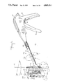
- FIG. 1 is a perspective view of an illustrative embodiment of the surgical fastener applying apparatus of the invention.
- FIG. 2 is a partly sectional elevational view of the apparatus of FIG. 1 showing an initial stage in the operating cycle of that apparatus.
- FIGS. 3 and 4 are views similar to FIG. 2 showing successive stages in the operating cycle of the apparatus of FIG. 1.
- FIG. 5 is a partly exploded perspective view of the apparatus of FIG. 1 in the condition shown in FIG. 2.
- FIG. 6 is a partly exploded perspective view of the distal portion of the apparatus of FIG. 1.
- FIG. 7 is a fragmentary perspective view of the distal portion the apparatus of FIG. 1.
- FIG. 8 is a further exploded perspective view of the distal portion of the apparatus of FIG. 1.
- FIG. 9 is a partly sectional elevational view of the distal portion of the apparatus of FIG. 1 in the condition shown FIG. 2.
- FIGS. 10-13 are views similar to FIG. 9 showing successive stages in the operating cycle of the apparatus of FIG. 1.
- FIGS. 10 and 11 show the same operating cycle stages as are shown in FIGS. 3 and 4, respectively.
- FIG. 14 is a sectional view taken along the line 14--14 in FIG. 10.
- FIG. 15 is a sectional view taken along the line 15--15 in FIG. 12.
- FIG. 16 is an exploded perspective view of the intermediate portion of the apparatus of FIG. 1.
- FIG. 17 is a partly sectional elevational view of the intermediate portion of the apparatus of FIG. 1.
- FIG. 18 is a view similar to FIG. 17 showing a different operating condition of the apparatus of FIG. 1.
- FIG. 19 is a partly sectional bottom plan view of the intermediate portion of the apparatus of FIG. 1 in the condition shown in FIG. 17.
- FIG. 20 is a sectional view taken along the line 20--20 in FIG. 17.
- FIG. 21 is a bottom plan view of the distal portion of the apparatus of FIG. 1.
- an illustrative embodiment of the surgical fastener applying apparatus or instrument 10 of this invention includes proximal actuator assembly 20, distal fastener applying assembly 200, and intermediate shaft assembly 100.
- Fastener applying assembly 200 includes proximal fastener holding part 210 which is mounted on the distal end of shaft assembly 100 for rotation by hand about axis 112, the rotational axis of first articulation 110.
- axis 112 is transverse to the longitudinal axis 102 of shaft assembly 100.
- axis 112 is perpendicular to axis 102, although that is not necessarily the case.
- axis 112 is parallel to the longitudinal axis of fastener holding part 210, although again that is not necessarily the case.
- Articulation 110 allows fastener applying assembly 200 to be moved to any rotational position about axis 112 within the limits indicated by the ends of double-headed arrow 114 in FIG. 1. In the depicted embodiment, fastener holding assembly 200 can be rotated approximately 90° to either side of axis 102 (total rotation approximately 180°).
- Shaft assembly 100 also includes a second articulation 140, the components of which are best seen in FIGS. 16-20 and which is described in greater detail below.
- articulation 140 allows the distal portion (including articulation 110) of shaft assembly 100 to be rotated by hand relative to the proximal portion of the shaft assembly about longitudinal axis 102.
- articulation 140 allows fastener applying assembly 200 to be moved to any rotational position about axis 102 within the limits indicated by the ends of double headed arrow 104 in FIGS. 1 and 20.
- actuator assembly 200 can be rotated about axis 102 at least about 90° in either direction from the position shown in FIG. 1 (total rotation at least about 180°), more preferably approximately 150° in either direction from the position shown in FIG. 1 (total rotation approximately 300°).
- a U-shaped frame 280 is movably mounted on fastener holding part 210.
- the proximal leg 282 of frame 280 is adjacent fastener holding part 210, while the distal leg 284 of frame 280 is distally spaced from fastener holding part 210.
- Anvil part 290 is mounted on distal leg 284.
- tissue 12 to be fastened is located between fastener holding part 210 and anvil part 290 with those parts spaced apart as shown in FIG. 2.
- Clamp actuator 50 is then pivoted down by hand toward the main body 30 of actuator assembly 20 as is shown progressively in FIGS. 3 and 4. This causes frame 280 to translate in the proximal direction, thereby clamping tissue 12 between fastener holding part 210 and anvil part 290.
- the tissue can now be fastened. This is accomplished by manually pivoting safety latch 60 down to the dotted line position shown in FIG. 4 and manually pivoting fastener actuator 70 back toward the dotted line position also shown in FIG. 4.
- Articulations 110 and 140 allow the surgeon to select any of a wide range of positions of fastener holding assembly 200 relative to actuator assembly 20, thereby greatly facilitating placement and use of instrument 10. Except for articulations 110 and 140 (and the moving parts associated with each of assemblies 20, 100, and 200), instrument 10 is a rigid structure. For example, there is no other axis parallel to axis 112 about which instrument 10 is flexible to any degree. This fact, combined with the detent and locking means associated with each articulation as described in detail below, allows the surgeon to first select the desired relative rotational positions of assemblies 20 and 200, and to thereafter fully control placement and operation of the instrument from the proximal end of the instrument.
- tissue is fastened by means of two-part interlocking fasteners which are typically made of a non-metallic resinous material
- metal surgical staples could also be used.
- depicted instrument 10 is designed to be discarded after a single use (thereby allowing the hospital to avoid all difficulty and expense associated with cleaning, sterilizing, and reloading the instrument for reuse), those skilled in the art will also appreciate that the apparatus could be made permanent and reusable if desired.
- main body 30 is made up of an interior frame structure 32 surrounded by two mirror-image shell members 34 and 36.
- Clamp actuator 50 is pivotally connected to main body 30 by means of pivot pin 42.
- Clamp actuator 50 is also pivotally connected by pivot pin 52 to one end of toggle link 54.
- the other end of toggle link 54 is pivotally connected by pivot pin 56 to clamp actuator cable anchor 58.
- Anchor 58 is mounted in main body 30 for reciprocal motion parallel to axis 102.
- the proximal end of clamp actuator cable 106 is fixedly attached to anchor 58.
- toggle link 54 causes anchor 58 to move in the proximal direction.
- Cable 106 is pulled in the proximal direction by anchor 58.
- Anchor 58 is releasably retained in the intermediate rest position shown in FIG. 3 by engagement of anchor tooth 59 with frame step 38. This holds actuator assembly 200 in the position shown in FIG. 3 even though the manual pivoting force has been removed from clamp actuator 50. The surgeon is thereby afforded an opportunity to inspect and, if necessary, adjust the placement of the instrument relative to tissue 12 while the tissue is substantially enclosed within fastener applying assembly 200 but before full clamping pressure has been applied to the tissue.
- the instrument can be reopened by lifting up on clamp actuator 50, thereby lifting anchor tooth 59 over step 38.
- Anchor 58 is also releasably retained in the proximal position shown in FIG. 4 by virtue of the fact that in that position, pivot pin 52 is slightly over center (i.e., slightly below a line connecting pivot pins 42 and 56 as viewed in FIG. 4).
- the instrument can be reopened from this position by lifting up on clamp actuator 50.
- Safety latch 60 is pivotally connected to main body 30 by pivot pin 44, and fastener actuator 70 is pivotally connected to main body 30 by pivot pin 46.
- the proximal end of fastener actuator cable 108 is fixedly attached to fastener actuator 70. Cable 108 is pulled in the proximal direction when fastener actuator 70 is pivoted as shown in FIG. 4.
- shaft assembly 100 is best seen in FIGS. 16-20.
- the principal structural member of shaft assembly 100 is tubular member 160 which is fixedly connected adjacent its proximal end to the frame structure 32 of actuator assembly 20. Cables 106 and 108 pass freely through tube 160.
- the proximal portion of tubular stem member 142 fits into the distal end of tube 160 and is rotatable relative to tube 160 to provide articulation 140. Cables 106 and 108 also pass freely through stem 142 into fastener holding part 210 which is pivotally mounted on the distal end of stem 142 to provide articulation 110.
- Stem 142 is retained in tube 160 by the projection of inwardly extending tube shoulders 162 into annular stem groove 144. Another inwardly extending tube shoulder 164 extends into stem groove 146. Groove 146 is interrupted on one side by stop member 148. Accordingly, stem 142 can rotate in either direction relative to tube 160 until stop member 148 contacts shoulder 164. Elements 148 and 164 therefore cooperate to provide stop means for articulation 140.
- Tube 160 is surrounded by another tubular structure including tube 170, collar 180, bushings 184 and 186, thrust ring 188, and locking ring 190.
- Tube 170 and locking ring 190 are rotatable relative to tube 160 Collar 180 is prevented from rotating relative to tube 160 by projection of collar keys 181 into tube keyways 166.
- Bushings 184 and 186 are made of a compressible material such as rubber.
- Thrust ring 188 is made of a relatively low friction material such as polytetrafluoroethylene to facilitate rotation of locking ring 190 relative to elements 180, 184, and 186.
- Tube 170 is constrained to rotate with stem 142 by virtue of the projection of stem keys 150 into keyways 172 near the distal end of tube 170.
- the end surfaces 178a and 178b of rack 174 respectively cooperate with the two side plates 218 of fastener holding part 210 to stop the pivoting of fastener applying assembly 200 about axis 112 when assembly 200 has been pivoted about 90° to either side of axis 102. Accordingly, surfaces 178 and plates 218 cooperate to provide stop means for articulation 110.
- locking ring 190 In the unlocked position, locking ring 190 is rotated so that proximally extending teeth 192 extend into relatively deep notches 40a in the distal end of main body 30. In this position of locking ring 190, bushings 184 and 186 are only very lightly compressed between thrust ring 188 and collar 180. Accordingly, collar 180 and tube 170 are relatively lightly and resiliently urged in the distal direction. Teeth 182 and 176 are therefore only lightly held in engagement with one another, and that engagement can be relatively easily overcome when fastener applying assembly 200 is deliberately rotated relative to actuator assembly 20 about axis 102. However, the engagement of teeth 182 and 176 is sufficient to releasably hold articulation 10 in any rotational position in which teeth 182 and 176 are engaged.
- Teeth 182 and 176 and their associated elements therefore comprise detent means for releasably retaining articulation 140 in any of a plurality of rotational positions.
- locking ring 190 is rotated so that teeth 192 are displaced from notches 40a (e.g., to relatively shallow notches 40b), locking ring 190 is thereby shifted somewhat in the distal direction.
- bushings 184 and 186 are more highly compressed, and collar 180 and tube 170 are strongly urged in the distal direction. This causes teeth 182 and 176 to engage one another much more securely, thereby locking articulation 140 in its current rotational position.
- the surgeon typically manually rotates fastener applying assembly 200 relative to actuator assembly 20 about either or both of articulation axes 102 and 112.
- Detent elements 116, 174, 176, and 182 releasably hold assemblies 20 and 200 in the selected relative positions.
- the surgeon rotates locking ring 190 so that teeth 192 move from notches 40a to notches 40b, thereby locking articulations 110 and 140 in their current positions. If further adjustment is required, locking ring 190 can, be rotated again to align teeth 192 with notches 40a, thereby unlocking articulations 110 and 140.
- fastener holding part 210 is, as has been mentioned, pivotally mounted on the distal end of stem 142 to provide articulation 110.
- Movably mounted on each side of fastener holding part 210 is a frame mounting cam plate 260a or 260b.
- Each of cam plates 260 is sandwiched between fastener holding part 210 and the adjacent lateral side of the proximal leg 282 of frame structure 280.
- Cam plates 260 are guided for vertical reciprocation relative to fastener holding part 210 by projection of cam followers 262 into cam slots 216 in the sides of fastener holding part 210.
- Frame 280 is positioned in relation to fastener holding part 210 by the projection of cam followers 286 into cam slots 264 in cam plates 260, by the projection of finger 288 between fastener holding part side plates 218, and by the projection of pin 289 into slots 220 in plates 218.
- Frame 280 is resiliently urged in the distal direction by prestressed compression coil spring 224 acting between fastener holding part 210 and frame 280.
- cam plates 260 has a finger 266 which extends into a vertical opening 222 near the rear of fastener holding part 210. Fingers 266 overlap one another inside opening 222, and the distal end of clamp actuator cable 106 is anchored to the fingers where they overlap (see FIG. 7). Cam plates 260 are resiliently urged upward relative to fastener holding part 210 by prestressed compression coil spring 226 acting between fingers 266 and a surface of fastener holding part 210.
- the distal end portion of cable 106 is redirected approximately 90° by the distal end portion of stem 142 from an alignment in shaft assembly 100 parallel to axis 102 to an alignment in fastener holding part 210 parallel to axis 112 (see FIGS. 7 and 9-13). Accordingly, when clamp actuator 50 pulls cable 106 in the proximal direction, the distal end of cable 106 pulls cam plates 260 vertically down relative to fastener holding part 210 as shown progressively in FIGS. 9-12. The presence of pin 289 in slots 220 prevents frame 280 from moving downwardly with cam plates 260.
- cam followers 286 are constrained to move up along cam slots 264, thereby causing frame 280 to move in the proximal direction.
- Pin 289 moves with frame 280 in the proximal direction, traversing slots 220.
- Cam slots 264 are shaped to cause distal frame leg 284 to first pivot into parallelism with the distal face of fastener holding part 210, and to then translate proximally toward fastener holding part 210 so that at the end of the stroke of clamp actuator 50, the tissue 12 to be fastened is clamped between the distal face of fastener holding part 210 and the parallel proximal face of anvil part 290.
- alignment pin 230 which automatically extends from fastener holding part 210 into anvil part 290 as tissue 12 is clamped.
- Alignment pin 230 is reciprocated by pin carrier 232 which is pivotally mounted on the rear of fastener holding part 210.
- Pin carrier 232 is resiliently biased to retract pin 230 in the proximal direction as shown in FIG. 9 by leaf spring 234.
- the lower portion of pin carrier 232 includes cam follower surface 236 which are in contact with cam surfaces 268 on the proximal edges of cam plates 260.
- Surfaces 236 and 268 are cooperatively shaped to allow spring 234 to proximally retract alignment pin 230 when cam plates 260 are in their uppermost positions, and to pivot pin carrier 232 and thereby distally extend alignment pin 230 as cam plates 260 are pulled down by cable 106.
- alignment pin 230 is fully extended and has begun to enter anvil aperture 292 as shown in FIG. 10. Accordingly, alignment pin 230 helps to confine tissue 12 to the space between fastener holding part 210 and anvil part 290 during any instrument placement adjustments the surgeon may wish to make and during final clamping of the tissue.
- tissue clamping continues as shown in FIG. 11, anvil aperture 292 is pulled farther onto the distal end of alignment pin 230, thereby ensuring proper alignment of fastener holding part 210 and anvil part 290.
- fastener parts 212 are driven by elements best seen in FIGS. 7-13 and 15.
- Fastener parts 212 are initially disposed in apertures 242 in holder 240 which forms the distal portion of fastener holding part 210.
- a pusher finger 244 extends into the rear of each aperture 242.
- Pusher fingers 244 may be advantageously interconnected in small groups (e.g., pairs) to reduce the number of separate parts and to stabilize the individual pusher fingers without creating a single large pusher structure that might tend to bind in apertures 242.
- the proximal ends of all of pusher fingers 244 are spanned by a single rigid pusher follower member 246.
- Pusher actuator 248 is located on the proximal side of follower 246 and is supported by cam follower pins 250 which extend into cam stages 252 in the side plates 218 of fastener holding part 210.
- the distal end of fastener actuator cable 108 is attached to pusher actuator 248.
- the distal end portion of cable 108 is redirected approximately 90° by the distal end portion of stem 142 from an alignment in shaft assembly 100 parallel to axis 102 to an alignment in fastener holding part 210 parallel to axis 112 in order to reach pusher actuator 248.
- fastener actuator 70 is operated to pull cable 108 in the proximal direction
- the distal end of cable 108 pulls down on pusher actuator 248.
- pusher actuator 248 moves down, it is also forced to move in the distal direction by cooperation of elements 250 and 252 (see FIG. 12).
- the distal motion of pusher actuator 248 is imparted to pusher fingers 244 via pusher follower 246, thereby driving fastener parts 212 partly through tissue 12 and into interlocking engagement with retainer parts 214 to fasten the tissue.
- proximally movable tension force transmitting members 106 and 108 which are both transversely and torsionally flexible.
- the transverse flexibility of cables 106 and 108 allows them to be redirected adjacent the distal end of stem 142.
- the path lengths of cables 106 and 108 are substantially unaffected by the rotational positions of articulations 110 and 140 because each cable is substantially coincident with the axis 102 or 112 of each articulation at the location of that articulation.
- cables 106 and 108 are both substantially coincident with axis 102 at the point where stem 142 rotates relative to tube 160.
- cables 106 and 108 twist slightly when articulation 140 is operated, but the path lengths of cables 106 and 108 do not change significantly.
- cables 106 and 108 are both substantially coincident with axis 112 at the point where fastener holding part 210 is rotatably mounted on stem 142.
- operation of articulation 140 causes cables 106 and 108 to twist slightly but does not significantly alter the path length of either cable.
- the term "coincident” means that cables 106 and 108 either approximately intersect or are approximately coaxial with the specified axis at the specified location.)
- the transverse and torsional flexibility of cables 106 and 108 and the constant path lengths of those cables facilitate articulation of the instrument as described above and allow operation of the instrument with articulations 110 and 140 at any of their rotational positions.
Abstract
Surgical fastener applying apparatus having an articulated shaft assembly intermediate a proximal actuator assembly and a distal fastener applying assembly. The rotational axis of the articulation is transverse to the proximal-distal axis of the shaft assembly. The apparatus is fully operational at any rotational position of the articulation. A detent mechanism may be included to releasably hold the articulation in any of its rotational positions. A locking mechanism may also be provided for locking the articulation in any of its rotational positions. The shaft assembly may also include a second articulation whose rotational axis is the proximal-distal axis. The apparatus is fully operational at any rotational position of the second articulation, and detent and locking mechanisms may also be associated with the second articulation.
Description
This is a division of application Ser. No. 771,845 filed Aug. 30, 1985, now U.S. Pat. No. 4,728,020.
This invention relates to surgical fastener applying apparatus, and more particularly to surgical fastener applying apparatus of the type that applies surgical fasteners to the body tissue clamped between relatively movable fastener holding and anvil parts of the apparatus.
Several types of surgical fastener applying instruments are known for applying surgical fasteners to body tissue clamped between relatively movable fastener holding and anvil parts of the apparatus. See, for example, Hirsch et al. U.S. Pat. No. 3,275,211. The surgical fasteners may be either metal staples as shown in the Hirsch et al. patent, or they may be non-metallic resinous materials as shown, for example, in Green U.S. Pat. No. 4,402,445. In the case of metal staples, the staple legs are typically driven through the tissue and clinched by the anvil to secure the staples in the tissue. In the case of non-metallic fasteners, each fastener may initially consist of two separate parts: a fastener part disposed in the fastener holding part of the apparatus, and a retainer part disposed in the anvil part of the apparatus. The leg or legs of the fastener parts are driven through the tissue and interlock with the retainer parts to secure the fasteners in the tissue. Although most metal surgical staples are biologically inert and therefore remain permanently in the body, biologically absorbable metal surgical staples are known. Surgical fasteners of non-metallic resinous materials can also be made either biologically absorbable or non-absorbable.
The type or form of the fasteners employed forms no part of the present invention. As used herein, the term "surgical fastener" is generic to all of the above-mentioned fastener types. Similarly, the terms "fastener holding part" and "anvil part" are also used generically herein.
In most of the known instruments for applying surgical fasteners to tissue clamped between the fastener holding and anvil parts of the instrument, the distal fastener applying assembly (which includes the fastener holding and anvil parts) of the instrument is rigidly connected to the proximal actuator portion of the instrument. This is true, for example, of the instruments shown in the abovementioned Hirsch et al. and Green patents.
Recently, however, there has been increasing interest in instruments in which the connection between the fastener applying assembly and the actuator assembly is not completely rigid. For example, Noiles et al. U.S. Pat. No. 4,473,077 shows a surgical stapler in which the shaft assembly connected between the fastener applying and actuator assemblies is transversely flexible in one plane (i.e., the plane of the paper in Noiles et al. FIG. 5). This may be a desirable feature in an instrument of the type shown by Noiles et al. which is intended for insertion into a tubular body organ. In such applications, the flexible shaft of the instrument conforms to the curvature of the surrounding body organ. However, in instruments which are not usually supported by surrounding body structures (e.g., instruments of the type shown in the above-mentioned Hirsch et al. and Green patents), excessive flexibility in the instrument between the fastener applying and actuator assemblies may mean that the location of the fastener applying assembly cannot be controlled from the actuator assembly and that each of these assemblies must be separately supported during placement of the instrument relative to the tissue to be fastened. This may mean that two people are required to handle the instrument during placement and removal.
In view of the foregoing, it is an object of this invention to provide surgical fastener applying apparatus of the type described above in which the fastener applying assembly is not rigidly connected to the actuator assembly, but in which the location of the fastener applying assembly can be substantially controlled from the actuator assembly.
It is another object of this invention to provide surgical fastener applying apparatus of the type described above in which the fastener applying assembly is not rigidly connected to the actuator assembly, but in which the fastener applying assembly can be completely controlled from the actuator assembly with the fastener applying assembly in any position relative to the actuator assembly.
These and other objects of the invention are accomplished in accordance with the principles of the invention by providing surgical fastener applying apparatus in which the fastener applying assembly is connected to the actuator assembly by a longitudinal shaft assembly including an articulation for allowing rotation of the fastener applying assembly relative to the actuator assembly about an axis which is transverse to the longitudinal axis of the shaft assembly. The shaft assembly is operative in any rotational position of the articulation to transmit from the actuator assembly to the fastener applying assembly the forces and motions ("work") necessary to operate the fastener applying assembly. The shaft assembly is also preferably rigid about all other axes parallel to the axis of rotation of the above-described articulation.
In the preferred embodiment, multi-position detent means are associated with the articulation to releasably retain the articulation in any of a plurality of rotational positions. Locking means may also be provided to lock the articulation in any of a plurality of rotational positions. Stop means may also be associated with the articulation to confine the articulation to a predetermined rotational range. Both the tissue clamping operation and the fastener applying operation are preferably completely controlled from the actuator assembly, and the necessary work is preferably transmitted from the actuator assembly to the fastener applying assembly by shaft assembly members which are proximally movable tension force transmitting members. These members are preferably transversely flexible adjacent to the articulation, and pass through the articulation along axes which are coincident with the axis of rotation of the articulation. The fastener applying part of the apparatus is preferably mounted at a fixed distance from the main body of the actuator assembly, and the anvil part is mounted so that it moves toward the fastener holding part in response to appropriate operation of the actuator assembly.
If desired, the shaft assembly may also include a second articulation for allowing rotation of the fastener applying assembly relative to the actuator assembly about the longitudinal axis of the shaft assembly. As in the case of the first articulation, the shaft assembly is operative in any rotational position of the second articulation to transmit from the actuator assembly to the fastener applying assembly the work necessary to operate the fastener applying assembly. Any or all of detent means, locking means, and stop means may be associated with the second articulation in a manner similar to the association of such elements with the first articulation.
Further features of the invention, its nature and various advantages will be more apparent from the accompanying drawings and the following detailed description of the invention.
FIG. 1 is a perspective view of an illustrative embodiment of the surgical fastener applying apparatus of the invention.
FIG. 2 is a partly sectional elevational view of the apparatus of FIG. 1 showing an initial stage in the operating cycle of that apparatus.
FIGS. 3 and 4 are views similar to FIG. 2 showing successive stages in the operating cycle of the apparatus of FIG. 1.
FIG. 5 is a partly exploded perspective view of the apparatus of FIG. 1 in the condition shown in FIG. 2.
FIG. 6 is a partly exploded perspective view of the distal portion of the apparatus of FIG. 1.
FIG. 7 is a fragmentary perspective view of the distal portion the apparatus of FIG. 1.
FIG. 8 is a further exploded perspective view of the distal portion of the apparatus of FIG. 1.
FIG. 9 is a partly sectional elevational view of the distal portion of the apparatus of FIG. 1 in the condition shown FIG. 2.
FIGS. 10-13 are views similar to FIG. 9 showing successive stages in the operating cycle of the apparatus of FIG. 1. FIGS. 10 and 11 show the same operating cycle stages as are shown in FIGS. 3 and 4, respectively.
FIG. 14 is a sectional view taken along the line 14--14 in FIG. 10.
FIG. 15 is a sectional view taken along the line 15--15 in FIG. 12.
FIG. 16 is an exploded perspective view of the intermediate portion of the apparatus of FIG. 1.
FIG. 17 is a partly sectional elevational view of the intermediate portion of the apparatus of FIG. 1.
FIG. 18 is a view similar to FIG. 17 showing a different operating condition of the apparatus of FIG. 1.
FIG. 19 is a partly sectional bottom plan view of the intermediate portion of the apparatus of FIG. 1 in the condition shown in FIG. 17.
FIG. 20 is a sectional view taken along the line 20--20 in FIG. 17.
FIG. 21 is a bottom plan view of the distal portion of the apparatus of FIG. 1.
As shown in FIG. 1, an illustrative embodiment of the surgical fastener applying apparatus or instrument 10 of this invention includes proximal actuator assembly 20, distal fastener applying assembly 200, and intermediate shaft assembly 100.
A U-shaped frame 280 is movably mounted on fastener holding part 210. In particular, the proximal leg 282 of frame 280 is adjacent fastener holding part 210, while the distal leg 284 of frame 280 is distally spaced from fastener holding part 210. Anvil part 290 is mounted on distal leg 284.
In use, after fastener applying assembly 200 has been properly oriented by manual operation of articulations 110 and 140, tissue 12 to be fastened is located between fastener holding part 210 and anvil part 290 with those parts spaced apart as shown in FIG. 2. Clamp actuator 50 is then pivoted down by hand toward the main body 30 of actuator assembly 20 as is shown progressively in FIGS. 3 and 4. This causes frame 280 to translate in the proximal direction, thereby clamping tissue 12 between fastener holding part 210 and anvil part 290. The tissue can now be fastened. This is accomplished by manually pivoting safety latch 60 down to the dotted line position shown in FIG. 4 and manually pivoting fastener actuator 70 back toward the dotted line position also shown in FIG. 4. This causes fastener holding part 210 to drive a plurality of surgical fastener parts 212 (FIGS. 9-13 and 15) from fastener holding part 210, partly through tissue 12, and into interlocking engagement with retainer parts 214 which are removably mounted in anvil part 290. The tissue fastening procedure is now complete and instrument 10 is removed from the tissue by manually pivoting clamp actuator 50 away from main body 30 to cause anvil part 290 to move distally away from fastener holding part 210, thereby releasing the clamping pressure on the tissue. After use as described above, instrument 10 is discarded. instrument 10 is fully operational in any rotational positions of articulations 110 and 140. Articulations 110 and 140 allow the surgeon to select any of a wide range of positions of fastener holding assembly 200 relative to actuator assembly 20, thereby greatly facilitating placement and use of instrument 10. Except for articulations 110 and 140 (and the moving parts associated with each of assemblies 20, 100, and 200), instrument 10 is a rigid structure. For example, there is no other axis parallel to axis 112 about which instrument 10 is flexible to any degree. This fact, combined with the detent and locking means associated with each articulation as described in detail below, allows the surgeon to first select the desired relative rotational positions of assemblies 20 and 200, and to thereafter fully control placement and operation of the instrument from the proximal end of the instrument.
Although in the depicted embodiment the tissue is fastened by means of two-part interlocking fasteners which are typically made of a non-metallic resinous material, those skilled in the art will appreciate that metal surgical staples could also be used. Similarly, although depicted instrument 10 is designed to be discarded after a single use (thereby allowing the hospital to avoid all difficulty and expense associated with cleaning, sterilizing, and reloading the instrument for reuse), those skilled in the art will also appreciate that the apparatus could be made permanent and reusable if desired.
Considering now the construction and operation of actuator assembly 20 in relation to FIGS. 2-5, main body 30 is made up of an interior frame structure 32 surrounded by two mirror- image shell members 34 and 36. Clamp actuator 50 is pivotally connected to main body 30 by means of pivot pin 42. Clamp actuator 50 is also pivotally connected by pivot pin 52 to one end of toggle link 54. The other end of toggle link 54 is pivotally connected by pivot pin 56 to clamp actuator cable anchor 58. Anchor 58 is mounted in main body 30 for reciprocal motion parallel to axis 102. The proximal end of clamp actuator cable 106 is fixedly attached to anchor 58.
When clamp actuator 50 is pivoted down toward main body 30 as is shown progressively in FIGS. 2-4, toggle link 54 causes anchor 58 to move in the proximal direction. Cable 106 is pulled in the proximal direction by anchor 58. Anchor 58 is releasably retained in the intermediate rest position shown in FIG. 3 by engagement of anchor tooth 59 with frame step 38. This holds actuator assembly 200 in the position shown in FIG. 3 even though the manual pivoting force has been removed from clamp actuator 50. The surgeon is thereby afforded an opportunity to inspect and, if necessary, adjust the placement of the instrument relative to tissue 12 while the tissue is substantially enclosed within fastener applying assembly 200 but before full clamping pressure has been applied to the tissue. If desired, the instrument can be reopened by lifting up on clamp actuator 50, thereby lifting anchor tooth 59 over step 38. Anchor 58 is also releasably retained in the proximal position shown in FIG. 4 by virtue of the fact that in that position, pivot pin 52 is slightly over center (i.e., slightly below a line connecting pivot pins 42 and 56 as viewed in FIG. 4). Once again, the instrument can be reopened from this position by lifting up on clamp actuator 50.
The construction of shaft assembly 100 is best seen in FIGS. 16-20. The principal structural member of shaft assembly 100 is tubular member 160 which is fixedly connected adjacent its proximal end to the frame structure 32 of actuator assembly 20. Cables 106 and 108 pass freely through tube 160. The proximal portion of tubular stem member 142 fits into the distal end of tube 160 and is rotatable relative to tube 160 to provide articulation 140. Cables 106 and 108 also pass freely through stem 142 into fastener holding part 210 which is pivotally mounted on the distal end of stem 142 to provide articulation 110.
In the unlocked position, locking ring 190 is rotated so that proximally extending teeth 192 extend into relatively deep notches 40a in the distal end of main body 30. In this position of locking ring 190, bushings 184 and 186 are only very lightly compressed between thrust ring 188 and collar 180. Accordingly, collar 180 and tube 170 are relatively lightly and resiliently urged in the distal direction. Teeth 182 and 176 are therefore only lightly held in engagement with one another, and that engagement can be relatively easily overcome when fastener applying assembly 200 is deliberately rotated relative to actuator assembly 20 about axis 102. However, the engagement of teeth 182 and 176 is sufficient to releasably hold articulation 10 in any rotational position in which teeth 182 and 176 are engaged. Teeth 182 and 176 and their associated elements therefore comprise detent means for releasably retaining articulation 140 in any of a plurality of rotational positions. On the other hand, when locking ring 190 is rotated so that teeth 192 are displaced from notches 40a (e.g., to relatively shallow notches 40b), locking ring 190 is thereby shifted somewhat in the distal direction. As a result, bushings 184 and 186 are more highly compressed, and collar 180 and tube 170 are strongly urged in the distal direction. This causes teeth 182 and 176 to engage one another much more securely, thereby locking articulation 140 in its current rotational position.
The above-described structure operates in a similar manner in relation to rack 174 and pinion 116. When locking ring teeth 192 are aligned with notches 40a, rack 174 engages pinion 116 only relatively lightly, and elements 116 and 174 therefore act as detent means for releasably holding articulation 110 in any of a plurality of rotational positions. When locking ring teeth 192 are not aligned with notches 40a, rack 174 engages pinion 116 much more securely, thereby locking articulation 110 in its current position.
In use, the surgeon typically manually rotates fastener applying assembly 200 relative to actuator assembly 20 about either or both of articulation axes 102 and 112. Detent elements 116, 174, 176, and 182 releasably hold assemblies 20 and 200 in the selected relative positions. When the surgeon is satisfied with the relative positions of assemblies 20 and 200, the surgeon rotates locking ring 190 so that teeth 192 move from notches 40a to notches 40b, thereby locking articulations 110 and 140 in their current positions. If further adjustment is required, locking ring 190 can, be rotated again to align teeth 192 with notches 40a, thereby unlocking articulations 110 and 140.
Considering now the detailed construction and operation of fastener applying assembly 200 as shown in FIGS. 6-15, fastener holding part 210 is, as has been mentioned, pivotally mounted on the distal end of stem 142 to provide articulation 110. Movably mounted on each side of fastener holding part 210 is a frame mounting cam plate 260a or 260b. Each of cam plates 260 is sandwiched between fastener holding part 210 and the adjacent lateral side of the proximal leg 282 of frame structure 280. Cam plates 260 are guided for vertical reciprocation relative to fastener holding part 210 by projection of cam followers 262 into cam slots 216 in the sides of fastener holding part 210. Frame 280 is positioned in relation to fastener holding part 210 by the projection of cam followers 286 into cam slots 264 in cam plates 260, by the projection of finger 288 between fastener holding part side plates 218, and by the projection of pin 289 into slots 220 in plates 218. Frame 280 is resiliently urged in the distal direction by prestressed compression coil spring 224 acting between fastener holding part 210 and frame 280.
Each of cam plates 260 has a finger 266 which extends into a vertical opening 222 near the rear of fastener holding part 210. Fingers 266 overlap one another inside opening 222, and the distal end of clamp actuator cable 106 is anchored to the fingers where they overlap (see FIG. 7). Cam plates 260 are resiliently urged upward relative to fastener holding part 210 by prestressed compression coil spring 226 acting between fingers 266 and a surface of fastener holding part 210.
In order to reach fingers 266, the distal end portion of cable 106 is redirected approximately 90° by the distal end portion of stem 142 from an alignment in shaft assembly 100 parallel to axis 102 to an alignment in fastener holding part 210 parallel to axis 112 (see FIGS. 7 and 9-13). Accordingly, when clamp actuator 50 pulls cable 106 in the proximal direction, the distal end of cable 106 pulls cam plates 260 vertically down relative to fastener holding part 210 as shown progressively in FIGS. 9-12. The presence of pin 289 in slots 220 prevents frame 280 from moving downwardly with cam plates 260. Accordingly, cam followers 286 are constrained to move up along cam slots 264, thereby causing frame 280 to move in the proximal direction. Pin 289 moves with frame 280 in the proximal direction, traversing slots 220. Cam slots 264 are shaped to cause distal frame leg 284 to first pivot into parallelism with the distal face of fastener holding part 210, and to then translate proximally toward fastener holding part 210 so that at the end of the stroke of clamp actuator 50, the tissue 12 to be fastened is clamped between the distal face of fastener holding part 210 and the parallel proximal face of anvil part 290.
Proper alignment between fastener holding part 210 and anvil part 290 is facilitated by alignment pin 230 which automatically extends from fastener holding part 210 into anvil part 290 as tissue 12 is clamped. Alignment pin 230 is reciprocated by pin carrier 232 which is pivotally mounted on the rear of fastener holding part 210. Pin carrier 232 is resiliently biased to retract pin 230 in the proximal direction as shown in FIG. 9 by leaf spring 234. The lower portion of pin carrier 232 includes cam follower surface 236 which are in contact with cam surfaces 268 on the proximal edges of cam plates 260. Surfaces 236 and 268 are cooperatively shaped to allow spring 234 to proximally retract alignment pin 230 when cam plates 260 are in their uppermost positions, and to pivot pin carrier 232 and thereby distally extend alignment pin 230 as cam plates 260 are pulled down by cable 106. By the time clamp actuator 50 has reached the intermediate rest position shown in FIG. 3 (with tooth 59 engaging step 38), alignment pin 230 is fully extended and has begun to enter anvil aperture 292 as shown in FIG. 10. Accordingly, alignment pin 230 helps to confine tissue 12 to the space between fastener holding part 210 and anvil part 290 during any instrument placement adjustments the surgeon may wish to make and during final clamping of the tissue. When tissue clamping continues as shown in FIG. 11, anvil aperture 292 is pulled farther onto the distal end of alignment pin 230, thereby ensuring proper alignment of fastener holding part 210 and anvil part 290.
After tissue 12 has been clamped as described above, fastener parts 212 are driven by elements best seen in FIGS. 7-13 and 15. Fastener parts 212 are initially disposed in apertures 242 in holder 240 which forms the distal portion of fastener holding part 210. A pusher finger 244 extends into the rear of each aperture 242. Pusher fingers 244 may be advantageously interconnected in small groups (e.g., pairs) to reduce the number of separate parts and to stabilize the individual pusher fingers without creating a single large pusher structure that might tend to bind in apertures 242. The proximal ends of all of pusher fingers 244 are spanned by a single rigid pusher follower member 246. Pusher actuator 248 is located on the proximal side of follower 246 and is supported by cam follower pins 250 which extend into cam stages 252 in the side plates 218 of fastener holding part 210.
The distal end of fastener actuator cable 108 is attached to pusher actuator 248. As in the case of cable 106, the distal end portion of cable 108 is redirected approximately 90° by the distal end portion of stem 142 from an alignment in shaft assembly 100 parallel to axis 102 to an alignment in fastener holding part 210 parallel to axis 112 in order to reach pusher actuator 248. When fastener actuator 70 is operated to pull cable 108 in the proximal direction, the distal end of cable 108 pulls down on pusher actuator 248. As pusher actuator 248 moves down, it is also forced to move in the distal direction by cooperation of elements 250 and 252 (see FIG. 12). The distal motion of pusher actuator 248 is imparted to pusher fingers 244 via pusher follower 246, thereby driving fastener parts 212 partly through tissue 12 and into interlocking engagement with retainer parts 214 to fasten the tissue.
After tissue 12 has been fastened as described above, the clamping pressure on the tissue is released by raising clamp actuator 50. Springs 224 and 226 restore cam plates 260 and frame 280 to their initial positions, and spring 234 causes proximal retraction of alignment pin 230. Accordingly, fastened tissue 12 is released from the instrument as shown in FIG. 13 and the instrument can be removed from the surgical site.
It should be noted that the work required for tissue clamping and fastener application is transmitted from actuator assembly 20 to fastener applying assembly 200 by proximally movable tension force transmitting members 106 and 108 which are both transversely and torsionally flexible. The transverse flexibility of cables 106 and 108 allows them to be redirected adjacent the distal end of stem 142. It should also be noted that the path lengths of cables 106 and 108 are substantially unaffected by the rotational positions of articulations 110 and 140 because each cable is substantially coincident with the axis 102 or 112 of each articulation at the location of that articulation. For example, cables 106 and 108 are both substantially coincident with axis 102 at the point where stem 142 rotates relative to tube 160. Accordingly, cables 106 and 108 twist slightly when articulation 140 is operated, but the path lengths of cables 106 and 108 do not change significantly. Similarly, cables 106 and 108 are both substantially coincident with axis 112 at the point where fastener holding part 210 is rotatably mounted on stem 142. Thus again, operation of articulation 140 causes cables 106 and 108 to twist slightly but does not significantly alter the path length of either cable. (As used in this context, the term "coincident" means that cables 106 and 108 either approximately intersect or are approximately coaxial with the specified axis at the specified location.) The transverse and torsional flexibility of cables 106 and 108 and the constant path lengths of those cables facilitate articulation of the instrument as described above and allow operation of the instrument with articulations 110 and 140 at any of their rotational positions.
Claims (17)
1. A surgical fastener applying apparatus comprising
a proximal actuator assembly having a main body and a clamp actuator movably mounted on said main body;
a shaft assembly extending from said main body;
a fastener holding part mounted on a distal and of said shaft assembly;
a U-shaped frame movably mounted on said fastener holding part, said frame having a distal leg and a proximal leg receiving said fastener holding part;
an anvil part mounted on said distal leg in facing elation to said fastener holding part; and
means connecting said clamp actuator to said frame for moving said frame proximally toward said fastener holding part to clamp tissue between said anvil part and said fastener holding part.
2. An apparatus as set forth in claim 1 which further comprises means for driving fasteners from said fastener holding part into tissue clamped said anvil part and said fastener holding part
3. An apparatus as set forth in claim 1 wherein said fastener holding part is pivotal about a first axis transverse to said shaft assembly and rotatable about a second axis parallel to said shaft assembly.
4. Apparatus for clamping tissue and applying a plurality of surgical fasteners in a linear array, to the clamped tissue comprising
a proximal actuator assembly including a main body and first means including a clamp actuator movably mounted on said body to produce work to clamp the tissue and a fastener actuator movably mounted on said main body for producing the work necessary to apply the fasteners;
a distal fastener applying assembly including (a) a U shaped frame having substantially parallel distal and proximal legs joined together at one end by a base, (b) an anvil part mounted on the distal leg of the frame, (c) a fastener holding part disposed adjacent the proximal leg of the frame (d) second means for moving said proximal leg toward the fastener holding part during movement of said U-shaped frame proximally toward the fastener holding part to clamp the tissue between the anvil part and the fastener holding part, and third means for driving the fasteners from the fastener holding part at least partly through the clamped tissue to the anvil part; and
a longitudinal shaft assembly fixed to and supporting the fastener holding part at a fixed distance from the main body and for operatively transmitting the work produced by the first means to the second and third means.
5. The apparatus defined in claim 4 wherein the second means comprises:
cam plates mounted on the fastener holding part for motion transverse to the longitudinal axis of the shaft assembly; and
cooperating cam and cam follower means on the frame and cam plates for causing the frame to move proximally in response to transverse motion of the cam plates.
6. The apparatus defined in claim 5 wherein the shaft assembly transmit work from said clamp actuator to the second means via a first proximally movable, transversely flexible, tension force transmitting member disposed in the shaft assembly, the distal end of the first member being connected to the cam plates at a point which is transversely spaced from the axis of the first member in the shaft assembly so that proximal motion of the first member produces transverse motion of the cam plates.
7. The apparatus defined in claim 4 wherin the third means drives the fasteners in the distal direction, wherein the shaft assembly transmits work from said fastener actuator to the third means via a second proximally movable, transversely flexible, tension force transmitting member disposed in the shaft assembly, and wherein the third means comprises fourth means for converting the proximal motion of the second member to distal motion of the fasteners.
8. The apparatus defined in claim 7 wherein the fourth means comprises:
a pusher actuator member movably mounted in the fastener holding part;
cooperating cam and cam follower means on the pusher actuator member and the fastener holding part for causing the pusher actuator member to move in the distal direction in response to motion of the pusher actuator member transverse to the longitudinal axis of the shaft assembly, the distal end of the second member being connected to the pusher actuator member at a point which is transversely spaced from the axis of the second member in the shaft assembly so that proximal motion of the second member produces transverse motion of the pusher actuator member; and
pusher means for applying the distal motion of the pusher actuator member to the fasteners.
9. The apparatus defined in claim 4 wherein the shaft assembly includes a first articulation for allowing rotation of the fastener applying assembly relative to the actuator assembly about a first axis which is transverse to the longitudinal axis of the shaft assembly, the shaft assembly being operative to transmit work from the first means to the second and third means at any rotational position of the first articulation.
10. The apparatus defined in claim 9 wherein the shaft assembly transmits work from the first means to the second and third means via proximally movable tension force transmitting members which are transversely and torsionally flexible adjacent the first articulation and which are coincident with the first axis adjacent the first articulation.
11. The apparatus defined in claim 10 wherein the first axis is adjacent the distal end of the shaft assembly and perpendicular to the longitudinal axis of the shaft assembly.
12. The apparatus defined in claim 9 wherein the shaft assembly further includes first detent means for releasably retaining the first articulation in any of a plurality of rotational positions.
13. The apparatus defined in claim 9 wherein the shaft assembly further includes first locking means for locking the first articulation in any of a plurality of rotational positions.
14. The apparatus defined in claim 4 wherein the shaft assembly includes a second articulation for allowing rotation of the fastener applying assembly relative to the actuator assembly about the longitudinal axis of the shaft assembly, the shaft assembly being operative to transmit work from the first means to the second and third means at any rotational position of the second articulation.
15. The apparatus defined in claim 14 wherein the shaft assembly transmits work from the first means to the second and third means via proximally movable tension force transmitting members which are transversely and torsionally flexible adjacent the second articulation and which are coincident with the longitudinal axis adjacent the second articulation.
16. The apparatus defined in claim 14 wherein the shaft assembly further includes second detent means for releasably retaining the second articulation in any of a plurality of rotational positions.
17. The apparatus defined in claim 14 wherein the shaft assembly further includes second locking means for locking the second articulation in any of a plurality of rotational positions.
Priority Applications (1)
| Application Number | Priority Date | Filing Date | Title |
|---|---|---|---|
| US07/161,987 US4869414A (en) | 1985-08-30 | 1988-02-29 | Articulated surgical fastener applying apparatus |
Applications Claiming Priority (2)
| Application Number | Priority Date | Filing Date | Title |
|---|---|---|---|
| US06/771,845 US4728020A (en) | 1985-08-30 | 1985-08-30 | Articulated surgical fastener applying apparatus |
| US07/161,987 US4869414A (en) | 1985-08-30 | 1988-02-29 | Articulated surgical fastener applying apparatus |
Related Parent Applications (1)
| Application Number | Title | Priority Date | Filing Date |
|---|---|---|---|
| US06/771,845 Division US4728020A (en) | 1985-08-30 | 1985-08-30 | Articulated surgical fastener applying apparatus |
Publications (1)
| Publication Number | Publication Date |
|---|---|
| US4869414A true US4869414A (en) | 1989-09-26 |
Family
ID=25093116
Family Applications (2)
| Application Number | Title | Priority Date | Filing Date |
|---|---|---|---|
| US06/771,845 Expired - Lifetime US4728020A (en) | 1985-08-30 | 1985-08-30 | Articulated surgical fastener applying apparatus |
| US07/161,987 Expired - Lifetime US4869414A (en) | 1985-08-30 | 1988-02-29 | Articulated surgical fastener applying apparatus |
Family Applications Before (1)
| Application Number | Title | Priority Date | Filing Date |
|---|---|---|---|
| US06/771,845 Expired - Lifetime US4728020A (en) | 1985-08-30 | 1985-08-30 | Articulated surgical fastener applying apparatus |
Country Status (8)
| Country | Link |
|---|---|
| US (2) | US4728020A (en) |
| EP (1) | EP0216532B1 (en) |
| JP (1) | JPS62101238A (en) |
| AT (1) | ATE61514T1 (en) |
| AU (1) | AU586882B2 (en) |
| BR (1) | BR8604158A (en) |
| CA (1) | CA1270170A (en) |
| DE (1) | DE3678080D1 (en) |
Cited By (630)
| Publication number | Priority date | Publication date | Assignee | Title |
|---|---|---|---|---|
| US4964559A (en) * | 1988-01-15 | 1990-10-23 | Ethicon, Inc. | Pneumatic surgical stapler connectors |
| US5005754A (en) * | 1990-04-04 | 1991-04-09 | Ethicon, Inc. | Bladder and mandrel for use with surgical stapler |
| US5137198A (en) * | 1991-05-16 | 1992-08-11 | Ethicon, Inc. | Fast closure device for linear surgical stapling instrument |
| US5381943A (en) * | 1992-10-09 | 1995-01-17 | Ethicon, Inc. | Endoscopic surgical stapling instrument with pivotable and rotatable staple cartridge |
| US5405073A (en) * | 1993-12-06 | 1995-04-11 | Ethicon, Inc. | Flexible support shaft assembly |
| US5409498A (en) * | 1992-11-05 | 1995-04-25 | Ethicon, Inc. | Rotatable articulating endoscopic fastening instrument |
| US5423471A (en) * | 1992-10-02 | 1995-06-13 | United States Surgical Corporation | Apparatus for applying two-part surgical fasteners in laparoscopic or endoscopic procedures |
| US5431323A (en) * | 1992-10-09 | 1995-07-11 | Ethicon, Inc. | Endoscopic surgical instrument with pivotable and rotatable staple cartridge |
| US5439155A (en) * | 1993-10-07 | 1995-08-08 | United States Surgical Corporation | Cartridge for surgical fastener applying apparatus |
| US5439156A (en) * | 1992-02-07 | 1995-08-08 | Ethicon, Inc. | Surgical anastomosis stapling instrument with flexible support shaft and anvil adjusting mechanism |
| US5452836A (en) * | 1994-02-07 | 1995-09-26 | Ethicon Endo-Surgery, Inc. | Surgical stapling instrument with improved jaw closure and staple firing actuator mechanism |
| US5465894A (en) * | 1993-12-06 | 1995-11-14 | Ethicon, Inc. | Surgical stapling instrument with articulated stapling head assembly on rotatable and flexible support shaft |
| US5484095A (en) * | 1992-03-31 | 1996-01-16 | United States Surgical Corporation | Apparatus for endoscopically applying staples individually to body tissue |
| US5485952A (en) * | 1992-09-23 | 1996-01-23 | United States Surgical Corporation | Apparatus for applying surgical fasteners |
| US5507773A (en) * | 1994-02-18 | 1996-04-16 | Ethicon Endo-Surgery | Cable-actuated jaw assembly for surgical instruments |
| US5509596A (en) * | 1991-10-18 | 1996-04-23 | United States Surgical Corporation | Apparatus for applying surgical fasteners |
| US5547117A (en) * | 1994-03-30 | 1996-08-20 | Ethicon Endo-Surgery | Handle actuator for surgical instrument having clamp lock and emergency release |
| US5558266A (en) * | 1991-10-18 | 1996-09-24 | United States Surgical Corporation | Apparatus for applying surgical fasteners |
| US5562682A (en) * | 1993-10-08 | 1996-10-08 | Richard-Allan Medical Industries, Inc. | Surgical Instrument with adjustable arms |
| US5564615A (en) * | 1992-10-09 | 1996-10-15 | Ethicon, Inc. | Surgical instrument |
| US5573169A (en) * | 1992-10-02 | 1996-11-12 | United States Surgical Corporation | Apparatus for applying two-part surgical fasteners in laparoscopic or endoscopic procedures |
| US5579978A (en) * | 1991-10-18 | 1996-12-03 | United States Surgical Corporation | Apparatus for applying surgical fasteners |
| US5626587A (en) * | 1992-10-09 | 1997-05-06 | Ethicon Endo-Surgery, Inc. | Method for operating a surgical instrument |
| US5630540A (en) * | 1995-05-24 | 1997-05-20 | United States Surgical Corporation | Surgical staple and staple drive member |
| US5662662A (en) * | 1992-10-09 | 1997-09-02 | Ethicon Endo-Surgery, Inc. | Surgical instrument and method |
| US5702408A (en) * | 1996-07-17 | 1997-12-30 | Ethicon Endo-Surgery, Inc. | Articulating surgical instrument |
| US5704534A (en) * | 1994-12-19 | 1998-01-06 | Ethicon Endo-Surgery, Inc. | Articulation assembly for surgical instruments |
| US5706998A (en) * | 1995-07-17 | 1998-01-13 | United States Surgical Corporation | Surgical stapler with alignment pin locking mechanism |
| US5713505A (en) * | 1996-05-13 | 1998-02-03 | Ethicon Endo-Surgery, Inc. | Articulation transmission mechanism for surgical instruments |
| US5735445A (en) * | 1995-03-07 | 1998-04-07 | United States Surgical Corporation | Surgical stapler |
| US5743456A (en) * | 1993-12-16 | 1998-04-28 | Stryker Corporation | Hand actuable surgical handpiece |
| US5810240A (en) * | 1996-03-15 | 1998-09-22 | United States Surgical Corporation | Surgical fastener applying device |
| US5823066A (en) * | 1996-05-13 | 1998-10-20 | Ethicon Endo-Surgery, Inc. | Articulation transmission mechanism for surgical instruments |
| US5893506A (en) * | 1994-03-01 | 1999-04-13 | United States Surgical Corporation | Surgical stapler with anvil sensor and lockout |
| US5954746A (en) * | 1997-10-09 | 1999-09-21 | Ethicon Endo-Surgery, Inc. | Dual cam trigger for a surgical instrument |
| US6053390A (en) * | 1992-05-19 | 2000-04-25 | United States Surgical | Anvil for surgical stapler |
| US6109500A (en) | 1996-10-04 | 2000-08-29 | United States Surgical Corporation | Lockout mechanism for a surgical stapler |
| WO2004032761A1 (en) * | 2002-10-04 | 2004-04-22 | Tyco Healthcare Group, Lp | Angled surgical fastener apparatus |
| US20040084505A1 (en) * | 2002-11-04 | 2004-05-06 | Federico Bilotti | Surgical stapling instrument |
| US6755338B2 (en) | 2001-08-29 | 2004-06-29 | Cerebral Vascular Applications, Inc. | Medical instrument |
| US20040164123A1 (en) * | 2000-10-13 | 2004-08-26 | Racenet David C. | Surgical stapling device |
| US6830174B2 (en) | 2000-08-30 | 2004-12-14 | Cerebral Vascular Applications, Inc. | Medical instrument |
| US20050139629A1 (en) * | 2003-12-30 | 2005-06-30 | Schwemberger Richard F. | Retaining pin leaver advancement mechanism for a curved cutter stapler |
| US20050247753A1 (en) * | 2003-12-30 | 2005-11-10 | Kelly William D | Surgical stapler having a plastic closure plate |
| US7011668B2 (en) | 2001-07-23 | 2006-03-14 | Dvl Acquistion Sub, Inc. | Surgical suturing instrument and method of use |
| US7037315B2 (en) | 2001-09-14 | 2006-05-02 | Dvl Aquisition Sub, Inc. | Surgical suturing instrument and method of use |
| US7131978B2 (en) | 2001-12-11 | 2006-11-07 | Dvl Acquisition Sub, Inc. | Surgical suturing instrument and method of use |
| US7131980B1 (en) | 2001-01-18 | 2006-11-07 | Dvl Acquisitions Sub, Inc. | Surgical suturing instrument and method of use |
| US20070095877A1 (en) * | 2000-10-13 | 2007-05-03 | Racenet David C | Surgical stapling device |
| US20070114261A1 (en) * | 2005-11-23 | 2007-05-24 | Ethicon Endo-Surgery, Inc. | Surgical stapler with a bendable end effector |
| US20070194080A1 (en) * | 2005-08-31 | 2007-08-23 | Swayze Jeffrey S | Surgical stapling device with staple driver that supports multiple wire diameter staples |
| US20070215670A1 (en) * | 2006-03-01 | 2007-09-20 | Hoffman Douglas B | Linear stapler with improved firing mechanism |
| US20070221702A1 (en) * | 2006-03-22 | 2007-09-27 | Kruszynski Michael L | Surgical stapler shaft cover |
| US20080083811A1 (en) * | 2006-10-06 | 2008-04-10 | Stanislaw Marczyk | Surgical instrument with articulating tool assembly |
| EP1932485A1 (en) * | 2006-12-14 | 2008-06-18 | Ethicon Endo-Surgery, Inc. | Laparoscopic stapling device |
| US7431189B2 (en) | 2006-08-02 | 2008-10-07 | Ethicon Endo-Surgery, Inc. | Pneumatically powered surgical cutting and fastening instrument with mechanical linkage coupling end effector and trigger motion |
| US7434717B2 (en) | 2007-01-11 | 2008-10-14 | Ethicon Endo-Surgery, Inc. | Apparatus for closing a curved anvil of a surgical stapling device |
| US7438209B1 (en) | 2007-03-15 | 2008-10-21 | Ethicon Endo-Surgery, Inc. | Surgical stapling instruments having a releasable staple-forming pocket |
| US7464846B2 (en) | 2006-01-31 | 2008-12-16 | Ethicon Endo-Surgery, Inc. | Surgical instrument having a removable battery |
| US7464849B2 (en) | 2006-01-31 | 2008-12-16 | Ethicon Endo-Surgery, Inc. | Electro-mechanical surgical instrument with closure system and anvil alignment components |
| US7467740B2 (en) | 2005-09-21 | 2008-12-23 | Ethicon Endo-Surgery, Inc. | Surgical stapling instruments having flexible channel and anvil features for adjustable staple heights |
| US7490749B2 (en) | 2007-03-28 | 2009-02-17 | Ethicon Endo-Surgery, Inc. | Surgical stapling and cutting instrument with manually retractable firing member |
| US7500979B2 (en) | 2005-08-31 | 2009-03-10 | Ethicon Endo-Surgery, Inc. | Surgical stapling device with multiple stacked actuator wedge cams for driving staple drivers |
| US7506791B2 (en) | 2006-09-29 | 2009-03-24 | Ethicon Endo-Surgery, Inc. | Surgical stapling instrument with mechanical mechanism for limiting maximum tissue compression |
| US7549564B2 (en) | 2007-06-22 | 2009-06-23 | Ethicon Endo-Surgery, Inc. | Surgical stapling instrument with an articulating end effector |
| US7568603B2 (en) | 2006-01-31 | 2009-08-04 | Ethicon Endo-Surgery, Inc. | Motor-driven surgical cutting and fastening instrument with articulatable end effector |
| US7575144B2 (en) | 2006-01-31 | 2009-08-18 | Ethicon Endo-Surgery, Inc. | Surgical fastener and cutter with single cable actuator |
| US7584880B2 (en) * | 2003-06-17 | 2009-09-08 | Tyco Healthcare Group Lp | Surgical stapling device |
| US7588175B2 (en) | 2007-06-18 | 2009-09-15 | Ethicon Endo-Surgery, Inc. | Surgical stapling and cutting instrument with improved firing system |
| US7597229B2 (en) | 2007-06-22 | 2009-10-06 | Ethicon Endo-Surgery, Inc. | End effector closure system for a surgical stapling instrument |
| US7604150B2 (en) | 2007-06-22 | 2009-10-20 | Ethicon Endo-Surgery, Inc. | Surgical stapling instrument with an anti-back up mechanism |
| US7607557B2 (en) | 2005-11-04 | 2009-10-27 | Ethicon Endo-Surgery, Inc. | Surgical stapling instruments structured for pump-assisted delivery of medical agents |
| US20090302093A1 (en) * | 2008-06-04 | 2009-12-10 | Tyco Healthcare Group Lp | Attachable clamp for surgical stapler |
| US7644848B2 (en) | 2006-01-31 | 2010-01-12 | Ethicon Endo-Surgery, Inc. | Electronic lockouts and surgical instrument including same |
| US7658311B2 (en) | 2007-06-22 | 2010-02-09 | Ethicon Endo-Surgery, Inc. | Surgical stapling instrument with a geared return mechanism |
| US7669746B2 (en) | 2005-08-31 | 2010-03-02 | Ethicon Endo-Surgery, Inc. | Staple cartridges for forming staples having differing formed staple heights |
| US7673783B2 (en) | 2005-11-04 | 2010-03-09 | Ethicon Endo-Surgery, Inc. | Surgical stapling instruments structured for delivery of medical agents |
| US20100089973A1 (en) * | 2008-10-10 | 2010-04-15 | Stanislaw Kostrzewski | Surgical instrument with pivotable jaw member |
| US7703653B2 (en) | 2007-09-28 | 2010-04-27 | Tyco Healthcare Group Lp | Articulation mechanism for surgical instrument |
| US7721931B2 (en) | 2007-01-10 | 2010-05-25 | Ethicon Endo-Surgery, Inc. | Prevention of cartridge reuse in a surgical instrument |
| US7721936B2 (en) | 2007-01-10 | 2010-05-25 | Ethicon Endo-Surgery, Inc. | Interlock and surgical instrument including same |
| US7738971B2 (en) | 2007-01-10 | 2010-06-15 | Ethicon Endo-Surgery, Inc. | Post-sterilization programming of surgical instruments |
| US7740159B2 (en) | 2006-08-02 | 2010-06-22 | Ethicon Endo-Surgery, Inc. | Pneumatically powered surgical cutting and fastening instrument with a variable control of the actuating rate of firing with mechanical power assist |
| US7753904B2 (en) | 2006-01-31 | 2010-07-13 | Ethicon Endo-Surgery, Inc. | Endoscopic surgical instrument with a handle that can articulate with respect to the shaft |
| US7753245B2 (en) | 2007-06-22 | 2010-07-13 | Ethicon Endo-Surgery, Inc. | Surgical stapling instruments |
| US20100178100A1 (en) * | 2006-10-06 | 2010-07-15 | Helmut Fricke | Lockable joint |
| US7766209B2 (en) | 2008-02-13 | 2010-08-03 | Ethicon Endo-Surgery, Inc. | Surgical stapling instrument with improved firing trigger arrangement |
| US7766210B2 (en) | 2006-01-31 | 2010-08-03 | Ethicon Endo-Surgery, Inc. | Motor-driven surgical cutting and fastening instrument with user feedback system |
| US7770775B2 (en) | 2006-01-31 | 2010-08-10 | Ethicon Endo-Surgery, Inc. | Motor-driven surgical cutting and fastening instrument with adaptive user feedback |
| US7793812B2 (en) | 2008-02-14 | 2010-09-14 | Ethicon Endo-Surgery, Inc. | Disposable motor-driven loading unit for use with a surgical cutting and stapling apparatus |
| US7798386B2 (en) | 2007-05-30 | 2010-09-21 | Ethicon Endo-Surgery, Inc. | Surgical instrument articulation joint cover |
| US7810692B2 (en) | 2008-02-14 | 2010-10-12 | Ethicon Endo-Surgery, Inc. | Disposable loading unit with firing indicator |
| US7810693B2 (en) | 2007-05-30 | 2010-10-12 | Ethicon Endo-Surgery, Inc. | Surgical stapling and cutting instrument with articulatable end effector |
| US7819296B2 (en) | 2008-02-14 | 2010-10-26 | Ethicon Endo-Surgery, Inc. | Surgical stapling apparatus with retractable firing systems |
| US7819298B2 (en) | 2008-02-14 | 2010-10-26 | Ethicon Endo-Surgery, Inc. | Surgical stapling apparatus with control features operable with one hand |
| US7819297B2 (en) | 2008-02-14 | 2010-10-26 | Ethicon Endo-Surgery, Inc. | Surgical stapling apparatus with reprocessible handle assembly |
| US7832612B2 (en) | 2008-09-19 | 2010-11-16 | Ethicon Endo-Surgery, Inc. | Lockout arrangement for a surgical stapler |
| US7845537B2 (en) | 2006-01-31 | 2010-12-07 | Ethicon Endo-Surgery, Inc. | Surgical instrument having recording capabilities |
| US20100324551A1 (en) * | 2009-06-18 | 2010-12-23 | Tyco Healthcare Group Lp | Laparoscopic shaft articulation by means of a rotating collar |
| US7857185B2 (en) | 2008-02-14 | 2010-12-28 | Ethicon Endo-Surgery, Inc. | Disposable loading unit for surgical stapling apparatus |
| US7861906B2 (en) | 2008-02-14 | 2011-01-04 | Ethicon Endo-Surgery, Inc. | Surgical stapling apparatus with articulatable components |
| US7866527B2 (en) | 2008-02-14 | 2011-01-11 | Ethicon Endo-Surgery, Inc. | Surgical stapling apparatus with interlockable firing system |
| US7900805B2 (en) | 2007-01-10 | 2011-03-08 | Ethicon Endo-Surgery, Inc. | Surgical instrument with enhanced battery performance |
| US20110062211A1 (en) * | 2006-10-06 | 2011-03-17 | Tyco Healthcare Group Lp | System and method for non-contact electronic articulation sensing |
| US20110068147A1 (en) * | 2008-05-05 | 2011-03-24 | Danyel Racenet | Surgical instrument with sequential clamping and cutting |
| US7913891B2 (en) | 2008-02-14 | 2011-03-29 | Ethicon Endo-Surgery, Inc. | Disposable loading unit with user feedback features and surgical instrument for use therewith |
| US7918376B1 (en) | 2009-03-09 | 2011-04-05 | Cardica, Inc. | Articulated surgical instrument |
| US7934630B2 (en) | 2005-08-31 | 2011-05-03 | Ethicon Endo-Surgery, Inc. | Staple cartridges for forming staples having differing formed staple heights |
| US7954682B2 (en) | 2007-01-10 | 2011-06-07 | Ethicon Endo-Surgery, Inc. | Surgical instrument with elements to communicate between control unit and end effector |
| US7959051B2 (en) | 2008-02-15 | 2011-06-14 | Ethicon Endo-Surgery, Inc. | Closure systems for a surgical cutting and stapling instrument |
| US7980443B2 (en) | 2008-02-15 | 2011-07-19 | Ethicon Endo-Surgery, Inc. | End effectors for a surgical cutting and stapling instrument |
| US8020743B2 (en) | 2008-10-15 | 2011-09-20 | Ethicon Endo-Surgery, Inc. | Powered articulatable surgical cutting and fastening instrument with flexible drive member |
| US8056787B2 (en) | 2007-03-28 | 2011-11-15 | Ethicon Endo-Surgery, Inc. | Surgical stapling and cutting instrument with travel-indicating retraction member |
| US8066167B2 (en) * | 2009-03-23 | 2011-11-29 | Ethicon Endo-Surgery, Inc. | Circular surgical stapling instrument with anvil locking system |
| US8074859B2 (en) | 2010-03-31 | 2011-12-13 | Tyco Healthcare Group Lp | Surgical instrument |
| US8096457B1 (en) | 2009-05-05 | 2012-01-17 | Cardica, Inc. | Articulation mechanisms for surgical instrument |
| US8100939B2 (en) | 2005-07-15 | 2012-01-24 | Incisive Surgical, Inc. | Mechanical method and apparatus for sequential tissue fastening |
| US8141762B2 (en) | 2009-10-09 | 2012-03-27 | Ethicon Endo-Surgery, Inc. | Surgical stapler comprising a staple pocket |
| RU2446748C2 (en) * | 2006-10-06 | 2012-04-10 | Орион Серджикал Гмбх | Lockable connection |
| US8157145B2 (en) | 2007-05-31 | 2012-04-17 | Ethicon Endo-Surgery, Inc. | Pneumatically powered surgical cutting and fastening instrument with electrical feedback |
| US8161977B2 (en) | 2006-01-31 | 2012-04-24 | Ethicon Endo-Surgery, Inc. | Accessing data stored in a memory of a surgical instrument |
| US8186555B2 (en) | 2006-01-31 | 2012-05-29 | Ethicon Endo-Surgery, Inc. | Motor-driven surgical cutting and fastening instrument with mechanical closure system |
| US8196796B2 (en) | 2007-06-04 | 2012-06-12 | Ethicon Endo-Surgery, Inc. | Shaft based rotary drive system for surgical instruments |
| US20120168484A1 (en) * | 2011-03-31 | 2012-07-05 | Paul Scirica | Locking articulation mechanism |
| US8215531B2 (en) | 2004-07-28 | 2012-07-10 | Ethicon Endo-Surgery, Inc. | Surgical stapling instrument having a medical substance dispenser |
| US8236010B2 (en) | 2006-03-23 | 2012-08-07 | Ethicon Endo-Surgery, Inc. | Surgical fastener and cutter with mimicking end effector |
| US20120199629A1 (en) * | 2011-02-04 | 2012-08-09 | Cappola Kenneth M | Locking articulation mechanism |
| US8267300B2 (en) | 2009-12-30 | 2012-09-18 | Ethicon Endo-Surgery, Inc. | Dampening device for endoscopic surgical stapler |
| US8308040B2 (en) | 2007-06-22 | 2012-11-13 | Ethicon Endo-Surgery, Inc. | Surgical stapling instrument with an articulatable end effector |
| US8322455B2 (en) | 2006-06-27 | 2012-12-04 | Ethicon Endo-Surgery, Inc. | Manually driven surgical cutting and fastening instrument |
| US8328064B2 (en) | 2009-05-06 | 2012-12-11 | Covidien Lp | Pin locking mechanism for a surgical instrument |
| US8328061B2 (en) | 2010-02-02 | 2012-12-11 | Covidien Lp | Surgical instrument for joining tissue |
| US8348124B2 (en) | 2011-02-08 | 2013-01-08 | Covidien Lp | Knife bar with geared overdrive |
| US8353439B2 (en) | 2009-11-19 | 2013-01-15 | Ethicon Endo-Surgery, Inc. | Circular stapler introducer with radially-openable distal end portion |
| US8353436B2 (en) | 2009-05-06 | 2013-01-15 | Covidien Lp | Pin locking mechanism for a surgical instrument |
| US8360296B2 (en) | 2010-09-09 | 2013-01-29 | Ethicon Endo-Surgery, Inc. | Surgical stapling head assembly with firing lockout for a surgical stapler |
| US8371491B2 (en) | 2008-02-15 | 2013-02-12 | Ethicon Endo-Surgery, Inc. | Surgical end effector having buttress retention features |
| US8393516B2 (en) | 2009-02-26 | 2013-03-12 | Covidien Lp | Surgical stapling apparatus with curved cartridge and anvil assemblies |
| US8393514B2 (en) | 2010-09-30 | 2013-03-12 | Ethicon Endo-Surgery, Inc. | Selectively orientable implantable fastener cartridge |
| US8397971B2 (en) | 2009-02-05 | 2013-03-19 | Ethicon Endo-Surgery, Inc. | Sterilizable surgical instrument |
| US8414577B2 (en) | 2009-02-05 | 2013-04-09 | Ethicon Endo-Surgery, Inc. | Surgical instruments and components for use in sterile environments |
| US8424740B2 (en) | 2007-06-04 | 2013-04-23 | Ethicon Endo-Surgery, Inc. | Surgical instrument having a directional switching mechanism |
| US8444036B2 (en) | 2009-02-06 | 2013-05-21 | Ethicon Endo-Surgery, Inc. | Motor driven surgical fastener device with mechanisms for adjusting a tissue gap within the end effector |
| US8453908B2 (en) | 2008-02-13 | 2013-06-04 | Ethicon Endo-Surgery, Inc. | Surgical stapling instrument with improved firing trigger arrangement |
| US8453907B2 (en) | 2009-02-06 | 2013-06-04 | Ethicon Endo-Surgery, Inc. | Motor driven surgical fastener device with cutting member reversing mechanism |
| US8453914B2 (en) | 2009-12-24 | 2013-06-04 | Ethicon Endo-Surgery, Inc. | Motor-driven surgical cutting instrument with electric actuator directional control assembly |
| US8459520B2 (en) | 2007-01-10 | 2013-06-11 | Ethicon Endo-Surgery, Inc. | Surgical instrument with wireless communication between control unit and remote sensor |
| US8459525B2 (en) | 2008-02-14 | 2013-06-11 | Ethicon Endo-Sugery, Inc. | Motorized surgical cutting and fastening instrument having a magnetic drive train torque limiting device |
| US8479969B2 (en) | 2007-01-10 | 2013-07-09 | Ethicon Endo-Surgery, Inc. | Drive interface for operably coupling a manipulatable surgical tool to a robot |
| US8485413B2 (en) | 2009-02-05 | 2013-07-16 | Ethicon Endo-Surgery, Inc. | Surgical stapling instrument comprising an articulation joint |
| US8517239B2 (en) | 2009-02-05 | 2013-08-27 | Ethicon Endo-Surgery, Inc. | Surgical stapling instrument comprising a magnetic element driver |
| US8534528B2 (en) | 2007-06-04 | 2013-09-17 | Ethicon Endo-Surgery, Inc. | Surgical instrument having a multiple rate directional switching mechanism |
| US8540133B2 (en) | 2008-09-19 | 2013-09-24 | Ethicon Endo-Surgery, Inc. | Staple cartridge |
| US8561870B2 (en) | 2008-02-13 | 2013-10-22 | Ethicon Endo-Surgery, Inc. | Surgical stapling instrument |
| US8573461B2 (en) | 2008-02-14 | 2013-11-05 | Ethicon Endo-Surgery, Inc. | Surgical stapling instruments with cam-driven staple deployment arrangements |
| US8573465B2 (en) | 2008-02-14 | 2013-11-05 | Ethicon Endo-Surgery, Inc. | Robotically-controlled surgical end effector system with rotary actuated closure systems |
| US8584919B2 (en) | 2008-02-14 | 2013-11-19 | Ethicon Endo-Sugery, Inc. | Surgical stapling apparatus with load-sensitive firing mechanism |
| US8602288B2 (en) | 2008-09-23 | 2013-12-10 | Ethicon Endo-Surgery. Inc. | Robotically-controlled motorized surgical end effector system with rotary actuated closure systems having variable actuation speeds |
| US8602287B2 (en) | 2008-09-23 | 2013-12-10 | Ethicon Endo-Surgery, Inc. | Motor driven surgical cutting instrument |
| US8608046B2 (en) | 2010-01-07 | 2013-12-17 | Ethicon Endo-Surgery, Inc. | Test device for a surgical tool |
| US8608045B2 (en) | 2008-10-10 | 2013-12-17 | Ethicon Endo-Sugery, Inc. | Powered surgical cutting and stapling apparatus with manually retractable firing system |
| US8616431B2 (en) | 2007-06-04 | 2013-12-31 | Ethicon Endo-Surgery, Inc. | Shiftable drive interface for robotically-controlled surgical tool |
| US8622274B2 (en) | 2008-02-14 | 2014-01-07 | Ethicon Endo-Surgery, Inc. | Motorized cutting and fastening instrument having control circuit for optimizing battery usage |
| US8632535B2 (en) | 2007-01-10 | 2014-01-21 | Ethicon Endo-Surgery, Inc. | Interlock and surgical instrument including same |
| US8636736B2 (en) | 2008-02-14 | 2014-01-28 | Ethicon Endo-Surgery, Inc. | Motorized surgical cutting and fastening instrument |
| US8657174B2 (en) | 2008-02-14 | 2014-02-25 | Ethicon Endo-Surgery, Inc. | Motorized surgical cutting and fastening instrument having handle based power source |
| US8708213B2 (en) | 2006-01-31 | 2014-04-29 | Ethicon Endo-Surgery, Inc. | Surgical instrument having a feedback system |
| US8721630B2 (en) | 2006-03-23 | 2014-05-13 | Ethicon Endo-Surgery, Inc. | Methods and devices for controlling articulation |
| US8740038B2 (en) | 2010-09-30 | 2014-06-03 | Ethicon Endo-Surgery, Inc. | Staple cartridge comprising a releasable portion |
| US8747238B2 (en) | 2012-06-28 | 2014-06-10 | Ethicon Endo-Surgery, Inc. | Rotary drive shaft assemblies for surgical instruments with articulatable end effectors |
| US8752749B2 (en) | 2008-02-14 | 2014-06-17 | Ethicon Endo-Surgery, Inc. | Robotically-controlled disposable motor-driven loading unit |
| US8758391B2 (en) | 2008-02-14 | 2014-06-24 | Ethicon Endo-Surgery, Inc. | Interchangeable tools for surgical instruments |
| US8763879B2 (en) | 2006-01-31 | 2014-07-01 | Ethicon Endo-Surgery, Inc. | Accessing data stored in a memory of surgical instrument |
| US8783541B2 (en) | 2003-05-20 | 2014-07-22 | Frederick E. Shelton, IV | Robotically-controlled surgical end effector system |
| US8789740B2 (en) | 2010-07-30 | 2014-07-29 | Ethicon Endo-Surgery, Inc. | Linear cutting and stapling device with selectively disengageable cutting member |
| US8789739B2 (en) | 2011-09-06 | 2014-07-29 | Ethicon Endo-Surgery, Inc. | Continuous stapling instrument |
| US8789741B2 (en) | 2010-09-24 | 2014-07-29 | Ethicon Endo-Surgery, Inc. | Surgical instrument with trigger assembly for generating multiple actuation motions |
| US8800838B2 (en) | 2005-08-31 | 2014-08-12 | Ethicon Endo-Surgery, Inc. | Robotically-controlled cable-based surgical end effectors |
| US8800841B2 (en) | 2011-03-15 | 2014-08-12 | Ethicon Endo-Surgery, Inc. | Surgical staple cartridges |
| US8820603B2 (en) | 2006-01-31 | 2014-09-02 | Ethicon Endo-Surgery, Inc. | Accessing data stored in a memory of a surgical instrument |
| US8827137B2 (en) | 2010-03-25 | 2014-09-09 | Covidien Lp | Pin alignment assembly for surgical stapler |
| US8844789B2 (en) | 2006-01-31 | 2014-09-30 | Ethicon Endo-Surgery, Inc. | Automated end effector component reloading system for use with a robotic system |
| US8875972B2 (en) | 2008-02-15 | 2014-11-04 | Ethicon Endo-Surgery, Inc. | End effector coupling arrangements for a surgical cutting and stapling instrument |
| US8893949B2 (en) | 2010-09-30 | 2014-11-25 | Ethicon Endo-Surgery, Inc. | Surgical stapler with floating anvil |
| US8893946B2 (en) | 2007-03-28 | 2014-11-25 | Ethicon Endo-Surgery, Inc. | Laparoscopic tissue thickness and clamp load measuring devices |
| US8905977B2 (en) | 2004-07-28 | 2014-12-09 | Ethicon Endo-Surgery, Inc. | Surgical stapling instrument having an electroactive polymer actuated medical substance dispenser |
| US8940000B2 (en) | 2010-05-12 | 2015-01-27 | Covidien Lp | Surgical instruments with flexible member attachment structures |
| US8992422B2 (en) | 2006-03-23 | 2015-03-31 | Ethicon Endo-Surgery, Inc. | Robotically-controlled endoscopic accessory channel |
| US9005230B2 (en) | 2008-09-23 | 2015-04-14 | Ethicon Endo-Surgery, Inc. | Motorized surgical instrument |
| US9028494B2 (en) | 2012-06-28 | 2015-05-12 | Ethicon Endo-Surgery, Inc. | Interchangeable end effector coupling arrangement |
| US9028519B2 (en) | 2008-09-23 | 2015-05-12 | Ethicon Endo-Surgery, Inc. | Motorized surgical instrument |
| US9038880B1 (en) | 2011-04-25 | 2015-05-26 | Cardica, Inc. | Articulated surgical instrument |
| US9044230B2 (en) | 2012-02-13 | 2015-06-02 | Ethicon Endo-Surgery, Inc. | Surgical cutting and fastening instrument with apparatus for determining cartridge and firing motion status |
| US9050084B2 (en) | 2011-09-23 | 2015-06-09 | Ethicon Endo-Surgery, Inc. | Staple cartridge including collapsible deck arrangement |
| US9055941B2 (en) | 2011-09-23 | 2015-06-16 | Ethicon Endo-Surgery, Inc. | Staple cartridge including collapsible deck |
| US9072535B2 (en) | 2011-05-27 | 2015-07-07 | Ethicon Endo-Surgery, Inc. | Surgical stapling instruments with rotatable staple deployment arrangements |
| US9072536B2 (en) | 2012-06-28 | 2015-07-07 | Ethicon Endo-Surgery, Inc. | Differential locking arrangements for rotary powered surgical instruments |
| US9078653B2 (en) | 2012-03-26 | 2015-07-14 | Ethicon Endo-Surgery, Inc. | Surgical stapling device with lockout system for preventing actuation in the absence of an installed staple cartridge |
| US9101358B2 (en) | 2012-06-15 | 2015-08-11 | Ethicon Endo-Surgery, Inc. | Articulatable surgical instrument comprising a firing drive |
| US9101385B2 (en) | 2012-06-28 | 2015-08-11 | Ethicon Endo-Surgery, Inc. | Electrode connections for rotary driven surgical tools |
| US9119657B2 (en) | 2012-06-28 | 2015-09-01 | Ethicon Endo-Surgery, Inc. | Rotary actuatable closure arrangement for surgical end effector |
| US9125662B2 (en) | 2012-06-28 | 2015-09-08 | Ethicon Endo-Surgery, Inc. | Multi-axis articulating and rotating surgical tools |
| US9198662B2 (en) | 2012-03-28 | 2015-12-01 | Ethicon Endo-Surgery, Inc. | Tissue thickness compensator having improved visibility |
| US9204880B2 (en) | 2012-03-28 | 2015-12-08 | Ethicon Endo-Surgery, Inc. | Tissue thickness compensator comprising capsules defining a low pressure environment |
| US9204879B2 (en) | 2012-06-28 | 2015-12-08 | Ethicon Endo-Surgery, Inc. | Flexible drive member |
| US9211134B2 (en) | 2012-04-09 | 2015-12-15 | Carefusion 2200, Inc. | Wrist assembly for articulating laparoscopic surgical instruments |
| US9211120B2 (en) | 2011-04-29 | 2015-12-15 | Ethicon Endo-Surgery, Inc. | Tissue thickness compensator comprising a plurality of medicaments |
| US9220500B2 (en) | 2010-09-30 | 2015-12-29 | Ethicon Endo-Surgery, Inc. | Tissue thickness compensator comprising structure to produce a resilient load |
| US9220501B2 (en) | 2010-09-30 | 2015-12-29 | Ethicon Endo-Surgery, Inc. | Tissue thickness compensators |
| US9226751B2 (en) | 2012-06-28 | 2016-01-05 | Ethicon Endo-Surgery, Inc. | Surgical instrument system including replaceable end effectors |
| US9232941B2 (en) | 2010-09-30 | 2016-01-12 | Ethicon Endo-Surgery, Inc. | Tissue thickness compensator comprising a reservoir |
| US9237891B2 (en) | 2005-08-31 | 2016-01-19 | Ethicon Endo-Surgery, Inc. | Robotically-controlled surgical stapling devices that produce formed staples having different lengths |
| US9272406B2 (en) | 2010-09-30 | 2016-03-01 | Ethicon Endo-Surgery, Llc | Fastener cartridge comprising a cutting member for releasing a tissue thickness compensator |
| US9283054B2 (en) | 2013-08-23 | 2016-03-15 | Ethicon Endo-Surgery, Llc | Interactive displays |
| US9282966B2 (en) | 2004-07-28 | 2016-03-15 | Ethicon Endo-Surgery, Inc. | Surgical stapling instrument |
| US9282974B2 (en) | 2012-06-28 | 2016-03-15 | Ethicon Endo-Surgery, Llc | Empty clip cartridge lockout |
| US9289256B2 (en) | 2012-06-28 | 2016-03-22 | Ethicon Endo-Surgery, Llc | Surgical end effectors having angled tissue-contacting surfaces |
| US9289208B1 (en) | 2009-05-05 | 2016-03-22 | Cardica, Inc. | Articulation insert for surgical instrument |
| US9301752B2 (en) | 2010-09-30 | 2016-04-05 | Ethicon Endo-Surgery, Llc | Tissue thickness compensator comprising a plurality of capsules |
| US9307989B2 (en) | 2012-03-28 | 2016-04-12 | Ethicon Endo-Surgery, Llc | Tissue stapler having a thickness compensator incorportating a hydrophobic agent |
| US9307986B2 (en) | 2013-03-01 | 2016-04-12 | Ethicon Endo-Surgery, Llc | Surgical instrument soft stop |
| US9314246B2 (en) | 2010-09-30 | 2016-04-19 | Ethicon Endo-Surgery, Llc | Tissue stapler having a thickness compensator incorporating an anti-inflammatory agent |
| US9320523B2 (en) | 2012-03-28 | 2016-04-26 | Ethicon Endo-Surgery, Llc | Tissue thickness compensator comprising tissue ingrowth features |
| US9332974B2 (en) | 2010-09-30 | 2016-05-10 | Ethicon Endo-Surgery, Llc | Layered tissue thickness compensator |
| US9332984B2 (en) | 2013-03-27 | 2016-05-10 | Ethicon Endo-Surgery, Llc | Fastener cartridge assemblies |
| US9332987B2 (en) | 2013-03-14 | 2016-05-10 | Ethicon Endo-Surgery, Llc | Control arrangements for a drive member of a surgical instrument |
| US9345481B2 (en) | 2013-03-13 | 2016-05-24 | Ethicon Endo-Surgery, Llc | Staple cartridge tissue thickness sensor system |
| US9358005B2 (en) | 2010-09-30 | 2016-06-07 | Ethicon Endo-Surgery, Llc | End effector layer including holding features |
| US9364233B2 (en) | 2010-09-30 | 2016-06-14 | Ethicon Endo-Surgery, Llc | Tissue thickness compensators for circular surgical staplers |
| US9386984B2 (en) | 2013-02-08 | 2016-07-12 | Ethicon Endo-Surgery, Llc | Staple cartridge comprising a releasable cover |
| US9474527B1 (en) | 2011-04-26 | 2016-10-25 | Bryan D. Knodel | Surgical instrument with discrete articulation |
| US9561038B2 (en) | 2012-06-28 | 2017-02-07 | Ethicon Endo-Surgery, Llc | Interchangeable clip applier |
| US9566048B1 (en) | 2011-04-26 | 2017-02-14 | Cardica, Inc. | Surgical instrument with discrete cammed articulation |
| US9572577B2 (en) | 2013-03-27 | 2017-02-21 | Ethicon Endo-Surgery, Llc | Fastener cartridge comprising a tissue thickness compensator including openings therein |
| US9574644B2 (en) | 2013-05-30 | 2017-02-21 | Ethicon Endo-Surgery, Llc | Power module for use with a surgical instrument |
| US9585657B2 (en) | 2008-02-15 | 2017-03-07 | Ethicon Endo-Surgery, Llc | Actuator for releasing a layer of material from a surgical end effector |
| US9597075B2 (en) | 2010-07-30 | 2017-03-21 | Ethicon Endo-Surgery, Inc. | Tissue acquisition arrangements and methods for surgical stapling devices |
| US9629814B2 (en) | 2010-09-30 | 2017-04-25 | Ethicon Endo-Surgery, Llc | Tissue thickness compensator configured to redistribute compressive forces |
| US9629629B2 (en) | 2013-03-14 | 2017-04-25 | Ethicon Endo-Surgey, LLC | Control systems for surgical instruments |
| US9649110B2 (en) | 2013-04-16 | 2017-05-16 | Ethicon Llc | Surgical instrument comprising a closing drive and a firing drive operated from the same rotatable output |
| US9690362B2 (en) | 2014-03-26 | 2017-06-27 | Ethicon Llc | Surgical instrument control circuit having a safety processor |
| US9693777B2 (en) | 2014-02-24 | 2017-07-04 | Ethicon Llc | Implantable layers comprising a pressed region |
| US9713472B2 (en) | 2002-06-25 | 2017-07-25 | Incisive Surgical, Inc. | Mechanical method and apparatus for bilateral tissue fastening |
| US9724098B2 (en) | 2012-03-28 | 2017-08-08 | Ethicon Endo-Surgery, Llc | Staple cartridge comprising an implantable layer |
| US9724094B2 (en) | 2014-09-05 | 2017-08-08 | Ethicon Llc | Adjunct with integrated sensors to quantify tissue compression |
| US9743929B2 (en) | 2014-03-26 | 2017-08-29 | Ethicon Llc | Modular powered surgical instrument with detachable shaft assemblies |
| US9775611B2 (en) | 2015-01-06 | 2017-10-03 | Covidien Lp | Clam shell surgical stapling loading unit |
| US9795384B2 (en) | 2013-03-27 | 2017-10-24 | Ethicon Llc | Fastener cartridge comprising a tissue thickness compensator and a gap setting element |
| US9795382B2 (en) | 2005-08-31 | 2017-10-24 | Ethicon Llc | Fastener cartridge assembly comprising a cam and driver arrangement |
| US9801627B2 (en) | 2014-09-26 | 2017-10-31 | Ethicon Llc | Fastener cartridge for creating a flexible staple line |
| US9808246B2 (en) | 2015-03-06 | 2017-11-07 | Ethicon Endo-Surgery, Llc | Method of operating a powered surgical instrument |
| US9814462B2 (en) | 2010-09-30 | 2017-11-14 | Ethicon Llc | Assembly for fastening tissue comprising a compressible layer |
| US9820738B2 (en) | 2014-03-26 | 2017-11-21 | Ethicon Llc | Surgical instrument comprising interactive systems |
| US9826978B2 (en) | 2010-09-30 | 2017-11-28 | Ethicon Llc | End effectors with same side closure and firing motions |
| US9833241B2 (en) | 2014-04-16 | 2017-12-05 | Ethicon Llc | Surgical fastener cartridges with driver stabilizing arrangements |
| US9844376B2 (en) | 2014-11-06 | 2017-12-19 | Ethicon Llc | Staple cartridge comprising a releasable adjunct material |
| US9844375B2 (en) | 2014-12-18 | 2017-12-19 | Ethicon Llc | Drive arrangements for articulatable surgical instruments |
| US9844374B2 (en) | 2014-12-18 | 2017-12-19 | Ethicon Llc | Surgical instrument systems comprising an articulatable end effector and means for adjusting the firing stroke of a firing member |
| US9855040B2 (en) | 2015-03-04 | 2018-01-02 | Covidien Lp | Surgical stapling loading unit having articulating jaws |
| US9861359B2 (en) | 2006-01-31 | 2018-01-09 | Ethicon Llc | Powered surgical instruments with firing system lockout arrangements |
| US9895148B2 (en) | 2015-03-06 | 2018-02-20 | Ethicon Endo-Surgery, Llc | Monitoring speed control and precision incrementing of motor for powered surgical instruments |
| US9895147B2 (en) | 2005-11-09 | 2018-02-20 | Ethicon Llc | End effectors for surgical staplers |
| US9901342B2 (en) | 2015-03-06 | 2018-02-27 | Ethicon Endo-Surgery, Llc | Signal and power communication system positioned on a rotatable shaft |
| US9913642B2 (en) | 2014-03-26 | 2018-03-13 | Ethicon Llc | Surgical instrument comprising a sensor system |
| US9924944B2 (en) | 2014-10-16 | 2018-03-27 | Ethicon Llc | Staple cartridge comprising an adjunct material |
| US9924961B2 (en) | 2015-03-06 | 2018-03-27 | Ethicon Endo-Surgery, Llc | Interactive feedback system for powered surgical instruments |
| USD814632S1 (en) | 2016-10-21 | 2018-04-03 | Covidien Lp | Staple cartridge |
| US9931118B2 (en) | 2015-02-27 | 2018-04-03 | Ethicon Endo-Surgery, Llc | Reinforced battery for a surgical instrument |
| US9943309B2 (en) | 2014-12-18 | 2018-04-17 | Ethicon Llc | Surgical instruments with articulatable end effectors and movable firing beam support arrangements |
| US9962161B2 (en) | 2014-02-12 | 2018-05-08 | Ethicon Llc | Deliverable surgical instrument |
| US9987000B2 (en) | 2014-12-18 | 2018-06-05 | Ethicon Llc | Surgical instrument assembly comprising a flexible articulation system |
| US9993248B2 (en) | 2015-03-06 | 2018-06-12 | Ethicon Endo-Surgery, Llc | Smart sensors with local signal processing |
| US9993258B2 (en) | 2015-02-27 | 2018-06-12 | Ethicon Llc | Adaptable surgical instrument handle |
| US10004498B2 (en) | 2006-01-31 | 2018-06-26 | Ethicon Llc | Surgical instrument comprising a plurality of articulation joints |
| US10045776B2 (en) | 2015-03-06 | 2018-08-14 | Ethicon Llc | Control techniques and sub-processor contained within modular shaft with select control processing from handle |
| US10045781B2 (en) | 2014-06-13 | 2018-08-14 | Ethicon Llc | Closure lockout systems for surgical instruments |
| US10052044B2 (en) | 2015-03-06 | 2018-08-21 | Ethicon Llc | Time dependent evaluation of sensor data to determine stability, creep, and viscoelastic elements of measures |
| US10052102B2 (en) | 2015-06-18 | 2018-08-21 | Ethicon Llc | Surgical end effectors with dual cam actuated jaw closing features |
| US10076326B2 (en) | 2015-09-23 | 2018-09-18 | Ethicon Llc | Surgical stapler having current mirror-based motor control |
| US10076325B2 (en) | 2014-10-13 | 2018-09-18 | Ethicon Llc | Surgical stapling apparatus comprising a tissue stop |
| US10085747B2 (en) | 2015-09-11 | 2018-10-02 | Incisive Surgical, Inc. | Surgical fastening instrument |
| US10085751B2 (en) | 2015-09-23 | 2018-10-02 | Ethicon Llc | Surgical stapler having temperature-based motor control |
| US10085748B2 (en) | 2014-12-18 | 2018-10-02 | Ethicon Llc | Locking arrangements for detachable shaft assemblies with articulatable surgical end effectors |
| US10092292B2 (en) | 2013-02-28 | 2018-10-09 | Ethicon Llc | Staple forming features for surgical stapling instrument |
| US10098642B2 (en) | 2015-08-26 | 2018-10-16 | Ethicon Llc | Surgical staples comprising features for improved fastening of tissue |
| US10105139B2 (en) | 2015-09-23 | 2018-10-23 | Ethicon Llc | Surgical stapler having downstream current-based motor control |
| US10117649B2 (en) | 2014-12-18 | 2018-11-06 | Ethicon Llc | Surgical instrument assembly comprising a lockable articulation system |
| US10130359B2 (en) | 2006-09-29 | 2018-11-20 | Ethicon Llc | Method for forming a staple |
| US10172620B2 (en) | 2015-09-30 | 2019-01-08 | Ethicon Llc | Compressible adjuncts with bonding nodes |
| US10172619B2 (en) | 2015-09-02 | 2019-01-08 | Ethicon Llc | Surgical staple driver arrays |
| US10180463B2 (en) | 2015-02-27 | 2019-01-15 | Ethicon Llc | Surgical apparatus configured to assess whether a performance parameter of the surgical apparatus is within an acceptable performance band |
| US10188385B2 (en) | 2014-12-18 | 2019-01-29 | Ethicon Llc | Surgical instrument system comprising lockable systems |
| US10211586B2 (en) | 2017-06-28 | 2019-02-19 | Ethicon Llc | Surgical shaft assemblies with watertight housings |
| US10206676B2 (en) | 2008-02-14 | 2019-02-19 | Ethicon Llc | Surgical cutting and fastening instrument |
| US10213201B2 (en) | 2015-03-31 | 2019-02-26 | Ethicon Llc | Stapling end effector configured to compensate for an uneven gap between a first jaw and a second jaw |
| US10226249B2 (en) | 2013-03-01 | 2019-03-12 | Ethicon Llc | Articulatable surgical instruments with conductive pathways for signal communication |
| US10238386B2 (en) | 2015-09-23 | 2019-03-26 | Ethicon Llc | Surgical stapler having motor control based on an electrical parameter related to a motor current |
| US10245033B2 (en) | 2015-03-06 | 2019-04-02 | Ethicon Llc | Surgical instrument comprising a lockable battery housing |
| US10245030B2 (en) | 2016-02-09 | 2019-04-02 | Ethicon Llc | Surgical instruments with tensioning arrangements for cable driven articulation systems |
| US10258418B2 (en) | 2017-06-29 | 2019-04-16 | Ethicon Llc | System for controlling articulation forces |
| US10258331B2 (en) | 2016-02-12 | 2019-04-16 | Ethicon Llc | Mechanisms for compensating for drivetrain failure in powered surgical instruments |
| US10265068B2 (en) | 2015-12-30 | 2019-04-23 | Ethicon Llc | Surgical instruments with separable motors and motor control circuits |
| US10265065B2 (en) | 2013-12-23 | 2019-04-23 | Ethicon Llc | Surgical staples and staple cartridges |
| US10271849B2 (en) | 2015-09-30 | 2019-04-30 | Ethicon Llc | Woven constructs with interlocked standing fibers |
| US10271851B2 (en) | 2016-04-01 | 2019-04-30 | Ethicon Llc | Modular surgical stapling system comprising a display |
| USD847989S1 (en) | 2016-06-24 | 2019-05-07 | Ethicon Llc | Surgical fastener cartridge |
| US10285705B2 (en) | 2016-04-01 | 2019-05-14 | Ethicon Llc | Surgical stapling system comprising a grooved forming pocket |
| US10292704B2 (en) | 2015-12-30 | 2019-05-21 | Ethicon Llc | Mechanisms for compensating for battery pack failure in powered surgical instruments |
| US10299878B2 (en) | 2015-09-25 | 2019-05-28 | Ethicon Llc | Implantable adjunct systems for determining adjunct skew |
| US10307170B2 (en) | 2017-06-20 | 2019-06-04 | Ethicon Llc | Method for closed loop control of motor velocity of a surgical stapling and cutting instrument |
| US10307159B2 (en) | 2016-04-01 | 2019-06-04 | Ethicon Llc | Surgical instrument handle assembly with reconfigurable grip portion |
| USD850617S1 (en) | 2016-06-24 | 2019-06-04 | Ethicon Llc | Surgical fastener cartridge |
| USD851762S1 (en) | 2017-06-28 | 2019-06-18 | Ethicon Llc | Anvil |
| US10327767B2 (en) | 2017-06-20 | 2019-06-25 | Ethicon Llc | Control of motor velocity of a surgical stapling and cutting instrument based on angle of articulation |
| US10327769B2 (en) | 2015-09-23 | 2019-06-25 | Ethicon Llc | Surgical stapler having motor control based on a drive system component |
| US10335145B2 (en) | 2016-04-15 | 2019-07-02 | Ethicon Llc | Modular surgical instrument with configurable operating mode |
| USD854151S1 (en) | 2017-06-28 | 2019-07-16 | Ethicon Llc | Surgical instrument shaft |
| US10357247B2 (en) | 2016-04-15 | 2019-07-23 | Ethicon Llc | Surgical instrument with multiple program responses during a firing motion |
| US10363037B2 (en) | 2016-04-18 | 2019-07-30 | Ethicon Llc | Surgical instrument system comprising a magnetic lockout |
| US10363036B2 (en) | 2015-09-23 | 2019-07-30 | Ethicon Llc | Surgical stapler having force-based motor control |
| US10368864B2 (en) | 2017-06-20 | 2019-08-06 | Ethicon Llc | Systems and methods for controlling displaying motor velocity for a surgical instrument |
| US10368865B2 (en) | 2015-12-30 | 2019-08-06 | Ethicon Llc | Mechanisms for compensating for drivetrain failure in powered surgical instruments |
| US10390841B2 (en) | 2017-06-20 | 2019-08-27 | Ethicon Llc | Control of motor velocity of a surgical stapling and cutting instrument based on angle of articulation |
| US10398434B2 (en) | 2017-06-29 | 2019-09-03 | Ethicon Llc | Closed loop velocity control of closure member for robotic surgical instrument |
| US10405859B2 (en) | 2016-04-15 | 2019-09-10 | Ethicon Llc | Surgical instrument with adjustable stop/start control during a firing motion |
| US10413294B2 (en) | 2012-06-28 | 2019-09-17 | Ethicon Llc | Shaft assembly arrangements for surgical instruments |
| US10426481B2 (en) | 2014-02-24 | 2019-10-01 | Ethicon Llc | Implantable layer assemblies |
| US10426467B2 (en) | 2016-04-15 | 2019-10-01 | Ethicon Llc | Surgical instrument with detection sensors |
| US10426471B2 (en) | 2016-12-21 | 2019-10-01 | Ethicon Llc | Surgical instrument with multiple failure response modes |
| US10448950B2 (en) | 2016-12-21 | 2019-10-22 | Ethicon Llc | Surgical staplers with independently actuatable closing and firing systems |
| US10448948B2 (en) | 2016-02-12 | 2019-10-22 | Ethicon Llc | Mechanisms for compensating for drivetrain failure in powered surgical instruments |
| US10456137B2 (en) | 2016-04-15 | 2019-10-29 | Ethicon Llc | Staple formation detection mechanisms |
| US10485543B2 (en) | 2016-12-21 | 2019-11-26 | Ethicon Llc | Anvil having a knife slot width |
| US10492783B2 (en) | 2016-04-15 | 2019-12-03 | Ethicon, Llc | Surgical instrument with improved stop/start control during a firing motion |
| US10492785B2 (en) | 2016-12-21 | 2019-12-03 | Ethicon Llc | Shaft assembly comprising a lockout |
| USD869655S1 (en) | 2017-06-28 | 2019-12-10 | Ethicon Llc | Surgical fastener cartridge |
| US10499914B2 (en) | 2016-12-21 | 2019-12-10 | Ethicon Llc | Staple forming pocket arrangements |
| US10517596B2 (en) | 2016-12-21 | 2019-12-31 | Ethicon Llc | Articulatable surgical instruments with articulation stroke amplification features |
| US10517594B2 (en) | 2014-10-29 | 2019-12-31 | Ethicon Llc | Cartridge assemblies for surgical staplers |
| US10537324B2 (en) | 2016-12-21 | 2020-01-21 | Ethicon Llc | Stepped staple cartridge with asymmetrical staples |
| US10537325B2 (en) | 2016-12-21 | 2020-01-21 | Ethicon Llc | Staple forming pocket arrangement to accommodate different types of staples |
| US10542979B2 (en) | 2016-06-24 | 2020-01-28 | Ethicon Llc | Stamped staples and staple cartridges using the same |
| US10568652B2 (en) | 2006-09-29 | 2020-02-25 | Ethicon Llc | Surgical staples having attached drivers of different heights and stapling instruments for deploying the same |
| US10568625B2 (en) | 2016-12-21 | 2020-02-25 | Ethicon Llc | Staple cartridges and arrangements of staples and staple cavities therein |
| US10568626B2 (en) | 2016-12-21 | 2020-02-25 | Ethicon Llc | Surgical instruments with jaw opening features for increasing a jaw opening distance |
| US10575868B2 (en) | 2013-03-01 | 2020-03-03 | Ethicon Llc | Surgical instrument with coupler assembly |
| US10588632B2 (en) | 2016-12-21 | 2020-03-17 | Ethicon Llc | Surgical end effectors and firing members thereof |
| US10588612B2 (en) | 2011-03-14 | 2020-03-17 | Ethicon Llc | Collapsible anvil plate assemblies for circular surgical stapling devices |
| US10588633B2 (en) | 2017-06-28 | 2020-03-17 | Ethicon Llc | Surgical instruments with open and closable jaws and axially movable firing member that is initially parked in close proximity to the jaws prior to firing |
| USD879808S1 (en) | 2017-06-20 | 2020-03-31 | Ethicon Llc | Display panel with graphical user interface |
| USD879809S1 (en) | 2017-06-20 | 2020-03-31 | Ethicon Llc | Display panel with changeable graphical user interface |
| US10617412B2 (en) | 2015-03-06 | 2020-04-14 | Ethicon Llc | System for detecting the mis-insertion of a staple cartridge into a surgical stapler |
| US10617418B2 (en) | 2015-08-17 | 2020-04-14 | Ethicon Llc | Implantable layers for a surgical instrument |
| US10617413B2 (en) | 2016-04-01 | 2020-04-14 | Ethicon Llc | Closure system arrangements for surgical cutting and stapling devices with separate and distinct firing shafts |
| US10624633B2 (en) | 2017-06-20 | 2020-04-21 | Ethicon Llc | Systems and methods for controlling motor velocity of a surgical stapling and cutting instrument |
| US10631859B2 (en) | 2017-06-27 | 2020-04-28 | Ethicon Llc | Articulation systems for surgical instruments |
| US10646220B2 (en) | 2017-06-20 | 2020-05-12 | Ethicon Llc | Systems and methods for controlling displacement member velocity for a surgical instrument |
| US10667809B2 (en) | 2016-12-21 | 2020-06-02 | Ethicon Llc | Staple cartridge and staple cartridge channel comprising windows defined therein |
| US10675028B2 (en) | 2006-01-31 | 2020-06-09 | Ethicon Llc | Powered surgical instruments with firing system lockout arrangements |
| US10682134B2 (en) | 2017-12-21 | 2020-06-16 | Ethicon Llc | Continuous use self-propelled stapling instrument |
| US10687813B2 (en) | 2017-12-15 | 2020-06-23 | Ethicon Llc | Adapters with firing stroke sensing arrangements for use in connection with electromechanical surgical instruments |
| US10687806B2 (en) | 2015-03-06 | 2020-06-23 | Ethicon Llc | Adaptive tissue compression techniques to adjust closure rates for multiple tissue types |
| US10687810B2 (en) | 2016-12-21 | 2020-06-23 | Ethicon Llc | Stepped staple cartridge with tissue retention and gap setting features |
| US10695062B2 (en) | 2010-10-01 | 2020-06-30 | Ethicon Llc | Surgical instrument including a retractable firing member |
| US10702269B2 (en) | 2014-12-25 | 2020-07-07 | Covidien Lp | Surgical stapling devices |
| US10716614B2 (en) | 2017-06-28 | 2020-07-21 | Ethicon Llc | Surgical shaft assemblies with slip ring assemblies with increased contact pressure |
| USD890784S1 (en) | 2017-06-20 | 2020-07-21 | Ethicon Llc | Display panel with changeable graphical user interface |
| US10716565B2 (en) | 2017-12-19 | 2020-07-21 | Ethicon Llc | Surgical instruments with dual articulation drivers |
| US10729509B2 (en) | 2017-12-19 | 2020-08-04 | Ethicon Llc | Surgical instrument comprising closure and firing locking mechanism |
| US10729501B2 (en) | 2017-09-29 | 2020-08-04 | Ethicon Llc | Systems and methods for language selection of a surgical instrument |
| US10736636B2 (en) | 2014-12-10 | 2020-08-11 | Ethicon Llc | Articulatable surgical instrument system |
| US10743875B2 (en) | 2017-12-15 | 2020-08-18 | Ethicon Llc | Surgical end effectors with jaw stiffener arrangements configured to permit monitoring of firing member |
| US10743872B2 (en) | 2017-09-29 | 2020-08-18 | Ethicon Llc | System and methods for controlling a display of a surgical instrument |
| US10743874B2 (en) | 2017-12-15 | 2020-08-18 | Ethicon Llc | Sealed adapters for use with electromechanical surgical instruments |
| USD894389S1 (en) | 2016-06-24 | 2020-08-25 | Ethicon Llc | Surgical fastener |
| US10758229B2 (en) | 2016-12-21 | 2020-09-01 | Ethicon Llc | Surgical instrument comprising improved jaw control |
| US10758230B2 (en) | 2016-12-21 | 2020-09-01 | Ethicon Llc | Surgical instrument with primary and safety processors |
| US10765427B2 (en) | 2017-06-28 | 2020-09-08 | Ethicon Llc | Method for articulating a surgical instrument |
| US10765429B2 (en) | 2017-09-29 | 2020-09-08 | Ethicon Llc | Systems and methods for providing alerts according to the operational state of a surgical instrument |
| US10772629B2 (en) | 2017-06-27 | 2020-09-15 | Ethicon Llc | Surgical anvil arrangements |
| US10779825B2 (en) | 2017-12-15 | 2020-09-22 | Ethicon Llc | Adapters with end effector position sensing and control arrangements for use in connection with electromechanical surgical instruments |
| US10779826B2 (en) | 2017-12-15 | 2020-09-22 | Ethicon Llc | Methods of operating surgical end effectors |
| US10779824B2 (en) | 2017-06-28 | 2020-09-22 | Ethicon Llc | Surgical instrument comprising an articulation system lockable by a closure system |
| US10779820B2 (en) | 2017-06-20 | 2020-09-22 | Ethicon Llc | Systems and methods for controlling motor speed according to user input for a surgical instrument |
| US10779821B2 (en) | 2018-08-20 | 2020-09-22 | Ethicon Llc | Surgical stapler anvils with tissue stop features configured to avoid tissue pinch |
| US10779903B2 (en) | 2017-10-31 | 2020-09-22 | Ethicon Llc | Positive shaft rotation lock activated by jaw closure |
| US10796471B2 (en) | 2017-09-29 | 2020-10-06 | Ethicon Llc | Systems and methods of displaying a knife position for a surgical instrument |
| US10813639B2 (en) | 2017-06-20 | 2020-10-27 | Ethicon Llc | Closed loop feedback control of motor velocity of a surgical stapling and cutting instrument based on system conditions |
| US10828028B2 (en) | 2016-04-15 | 2020-11-10 | Ethicon Llc | Surgical instrument with multiple program responses during a firing motion |
| US10828033B2 (en) | 2017-12-15 | 2020-11-10 | Ethicon Llc | Handheld electromechanical surgical instruments with improved motor control arrangements for positioning components of an adapter coupled thereto |
| US10835330B2 (en) | 2017-12-19 | 2020-11-17 | Ethicon Llc | Method for determining the position of a rotatable jaw of a surgical instrument attachment assembly |
| US10842492B2 (en) | 2018-08-20 | 2020-11-24 | Ethicon Llc | Powered articulatable surgical instruments with clutching and locking arrangements for linking an articulation drive system to a firing drive system |
| US10842490B2 (en) | 2017-10-31 | 2020-11-24 | Ethicon Llc | Cartridge body design with force reduction based on firing completion |
| US10856870B2 (en) | 2018-08-20 | 2020-12-08 | Ethicon Llc | Switching arrangements for motor powered articulatable surgical instruments |
| US10856869B2 (en) | 2017-06-27 | 2020-12-08 | Ethicon Llc | Surgical anvil arrangements |
| US10869666B2 (en) | 2017-12-15 | 2020-12-22 | Ethicon Llc | Adapters with control systems for controlling multiple motors of an electromechanical surgical instrument |
| USD906355S1 (en) | 2017-06-28 | 2020-12-29 | Ethicon Llc | Display screen or portion thereof with a graphical user interface for a surgical instrument |
| US10881399B2 (en) | 2017-06-20 | 2021-01-05 | Ethicon Llc | Techniques for adaptive control of motor velocity of a surgical stapling and cutting instrument |
| US10881396B2 (en) | 2017-06-20 | 2021-01-05 | Ethicon Llc | Surgical instrument with variable duration trigger arrangement |
| USD907648S1 (en) | 2017-09-29 | 2021-01-12 | Ethicon Llc | Display screen or portion thereof with animated graphical user interface |
| US10888321B2 (en) | 2017-06-20 | 2021-01-12 | Ethicon Llc | Systems and methods for controlling velocity of a displacement member of a surgical stapling and cutting instrument |
| USD907647S1 (en) | 2017-09-29 | 2021-01-12 | Ethicon Llc | Display screen or portion thereof with animated graphical user interface |
| US10903685B2 (en) | 2017-06-28 | 2021-01-26 | Ethicon Llc | Surgical shaft assemblies with slip ring assemblies forming capacitive channels |
| US10898183B2 (en) | 2017-06-29 | 2021-01-26 | Ethicon Llc | Robotic surgical instrument with closed loop feedback techniques for advancement of closure member during firing |
| US10912559B2 (en) | 2018-08-20 | 2021-02-09 | Ethicon Llc | Reinforced deformable anvil tip for surgical stapler anvil |
| USD910847S1 (en) | 2017-12-19 | 2021-02-16 | Ethicon Llc | Surgical instrument assembly |
| US10925599B2 (en) | 2013-12-23 | 2021-02-23 | Ethicon Llc | Modular surgical instruments |
| US10932772B2 (en) | 2017-06-29 | 2021-03-02 | Ethicon Llc | Methods for closed loop velocity control for robotic surgical instrument |
| US10939910B2 (en) | 2016-12-02 | 2021-03-09 | Covidien Lp | Surgical stapling instrument with curved end effector |
| US10945727B2 (en) | 2016-12-21 | 2021-03-16 | Ethicon Llc | Staple cartridge with deformable driver retention features |
| US10945730B2 (en) | 2018-06-25 | 2021-03-16 | Covidien Lp | Stapling device with selectively advanceable alignment pin |
| US10945731B2 (en) | 2010-09-30 | 2021-03-16 | Ethicon Llc | Tissue thickness compensator comprising controlled release and expansion |
| USD914878S1 (en) | 2018-08-20 | 2021-03-30 | Ethicon Llc | Surgical instrument anvil |
| US10966718B2 (en) | 2017-12-15 | 2021-04-06 | Ethicon Llc | Dynamic clamping assemblies with improved wear characteristics for use in connection with electromechanical surgical instruments |
| US10980539B2 (en) | 2015-09-30 | 2021-04-20 | Ethicon Llc | Implantable adjunct comprising bonded layers |
| US10980537B2 (en) | 2017-06-20 | 2021-04-20 | Ethicon Llc | Closed loop feedback control of motor velocity of a surgical stapling and cutting instrument based on measured time over a specified number of shaft rotations |
| US10987102B2 (en) | 2010-09-30 | 2021-04-27 | Ethicon Llc | Tissue thickness compensator comprising a plurality of layers |
| USD917500S1 (en) | 2017-09-29 | 2021-04-27 | Ethicon Llc | Display screen or portion thereof with graphical user interface |
| US10993716B2 (en) | 2017-06-27 | 2021-05-04 | Ethicon Llc | Surgical anvil arrangements |
| US10993714B2 (en) | 2017-11-28 | 2021-05-04 | Covidien Lp | Surgical stapling instrument and associated trigger mechanisms |
| US10993715B2 (en) | 2016-12-21 | 2021-05-04 | Ethicon Llc | Staple cartridge comprising staples with different clamping breadths |
| US11006955B2 (en) | 2017-12-15 | 2021-05-18 | Ethicon Llc | End effectors with positive jaw opening features for use with adapters for electromechanical surgical instruments |
| US11007022B2 (en) | 2017-06-29 | 2021-05-18 | Ethicon Llc | Closed loop velocity control techniques based on sensed tissue parameters for robotic surgical instrument |
| US11020109B2 (en) | 2013-12-23 | 2021-06-01 | Ethicon Llc | Surgical stapling assembly for use with a powered surgical interface |
| US11020112B2 (en) | 2017-12-19 | 2021-06-01 | Ethicon Llc | Surgical tools configured for interchangeable use with different controller interfaces |
| US11033267B2 (en) | 2017-12-15 | 2021-06-15 | Ethicon Llc | Systems and methods of controlling a clamping member firing rate of a surgical instrument |
| US11039836B2 (en) | 2007-01-11 | 2021-06-22 | Cilag Gmbh International | Staple cartridge for use with a surgical stapling instrument |
| US11039834B2 (en) | 2018-08-20 | 2021-06-22 | Cilag Gmbh International | Surgical stapler anvils with staple directing protrusions and tissue stability features |
| US11045195B2 (en) | 2014-04-25 | 2021-06-29 | Incisive Surgical, Inc. | Method and apparatus for wound closure with sequential tissue positioning and retention |
| US11045192B2 (en) | 2018-08-20 | 2021-06-29 | Cilag Gmbh International | Fabricating techniques for surgical stapler anvils |
| US11045270B2 (en) | 2017-12-19 | 2021-06-29 | Cilag Gmbh International | Robotic attachment comprising exterior drive actuator |
| US11051813B2 (en) | 2006-01-31 | 2021-07-06 | Cilag Gmbh International | Powered surgical instruments with firing system lockout arrangements |
| US11051807B2 (en) | 2019-06-28 | 2021-07-06 | Cilag Gmbh International | Packaging assembly including a particulate trap |
| US11071543B2 (en) | 2017-12-15 | 2021-07-27 | Cilag Gmbh International | Surgical end effectors with clamping assemblies configured to increase jaw aperture ranges |
| US11071554B2 (en) | 2017-06-20 | 2021-07-27 | Cilag Gmbh International | Closed loop feedback control of motor velocity of a surgical stapling and cutting instrument based on magnitude of velocity error measurements |
| US11071545B2 (en) | 2014-09-05 | 2021-07-27 | Cilag Gmbh International | Smart cartridge wake up operation and data retention |
| US11076853B2 (en) | 2017-12-21 | 2021-08-03 | Cilag Gmbh International | Systems and methods of displaying a knife position during transection for a surgical instrument |
| US11083458B2 (en) | 2018-08-20 | 2021-08-10 | Cilag Gmbh International | Powered surgical instruments with clutching arrangements to convert linear drive motions to rotary drive motions |
| US11090075B2 (en) | 2017-10-30 | 2021-08-17 | Cilag Gmbh International | Articulation features for surgical end effector |
| US11090046B2 (en) | 2017-06-20 | 2021-08-17 | Cilag Gmbh International | Systems and methods for controlling displacement member motion of a surgical stapling and cutting instrument |
| US11123065B2 (en) | 2013-12-23 | 2021-09-21 | Cilag Gmbh International | Surgical cutting and stapling instruments with independent jaw control features |
| US11129680B2 (en) | 2017-12-21 | 2021-09-28 | Cilag Gmbh International | Surgical instrument comprising a projector |
| US11133106B2 (en) | 2013-08-23 | 2021-09-28 | Cilag Gmbh International | Surgical instrument assembly comprising a retraction assembly |
| US11134942B2 (en) | 2016-12-21 | 2021-10-05 | Cilag Gmbh International | Surgical stapling instruments and staple-forming anvils |
| US11134944B2 (en) | 2017-10-30 | 2021-10-05 | Cilag Gmbh International | Surgical stapler knife motion controls |
| US11141153B2 (en) | 2014-10-29 | 2021-10-12 | Cilag Gmbh International | Staple cartridges comprising driver arrangements |
| US11147551B2 (en) | 2019-03-25 | 2021-10-19 | Cilag Gmbh International | Firing drive arrangements for surgical systems |
| US11147553B2 (en) | 2019-03-25 | 2021-10-19 | Cilag Gmbh International | Firing drive arrangements for surgical systems |
| US11154301B2 (en) | 2015-02-27 | 2021-10-26 | Cilag Gmbh International | Modular stapling assembly |
| US11172929B2 (en) | 2019-03-25 | 2021-11-16 | Cilag Gmbh International | Articulation drive arrangements for surgical systems |
| US11179150B2 (en) | 2016-04-15 | 2021-11-23 | Cilag Gmbh International | Systems and methods for controlling a surgical stapling and cutting instrument |
| US11197671B2 (en) | 2012-06-28 | 2021-12-14 | Cilag Gmbh International | Stapling assembly comprising a lockout |
| US11197670B2 (en) | 2017-12-15 | 2021-12-14 | Cilag Gmbh International | Surgical end effectors with pivotal jaws configured to touch at their respective distal ends when fully closed |
| US11202633B2 (en) | 2014-09-26 | 2021-12-21 | Cilag Gmbh International | Surgical stapling buttresses and adjunct materials |
| US11207065B2 (en) | 2018-08-20 | 2021-12-28 | Cilag Gmbh International | Method for fabricating surgical stapler anvils |
| US11207064B2 (en) | 2011-05-27 | 2021-12-28 | Cilag Gmbh International | Automated end effector component reloading system for use with a robotic system |
| US11213293B2 (en) | 2016-02-09 | 2022-01-04 | Cilag Gmbh International | Articulatable surgical instruments with single articulation link arrangements |
| US11213295B2 (en) | 2015-09-02 | 2022-01-04 | Cilag Gmbh International | Surgical staple configurations with camming surfaces located between portions supporting surgical staples |
| US11219455B2 (en) | 2019-06-28 | 2022-01-11 | Cilag Gmbh International | Surgical instrument including a lockout key |
| US11219456B2 (en) | 2015-08-26 | 2022-01-11 | Cilag Gmbh International | Surgical staple strips for permitting varying staple properties and enabling easy cartridge loading |
| US11224497B2 (en) | 2019-06-28 | 2022-01-18 | Cilag Gmbh International | Surgical systems with multiple RFID tags |
| US11224426B2 (en) | 2016-02-12 | 2022-01-18 | Cilag Gmbh International | Mechanisms for compensating for drivetrain failure in powered surgical instruments |
| US11224427B2 (en) | 2006-01-31 | 2022-01-18 | Cilag Gmbh International | Surgical stapling system including a console and retraction assembly |
| US11224428B2 (en) | 2016-12-21 | 2022-01-18 | Cilag Gmbh International | Surgical stapling systems |
| US11229437B2 (en) | 2019-06-28 | 2022-01-25 | Cilag Gmbh International | Method for authenticating the compatibility of a staple cartridge with a surgical instrument |
| US11234698B2 (en) | 2019-12-19 | 2022-02-01 | Cilag Gmbh International | Stapling system comprising a clamp lockout and a firing lockout |
| US11241230B2 (en) | 2012-06-28 | 2022-02-08 | Cilag Gmbh International | Clip applier tool for use with a robotic surgical system |
| US11246592B2 (en) | 2017-06-28 | 2022-02-15 | Cilag Gmbh International | Surgical instrument comprising an articulation system lockable to a frame |
| US11246678B2 (en) | 2019-06-28 | 2022-02-15 | Cilag Gmbh International | Surgical stapling system having a frangible RFID tag |
| US11246590B2 (en) | 2005-08-31 | 2022-02-15 | Cilag Gmbh International | Staple cartridge including staple drivers having different unfired heights |
| US11253254B2 (en) | 2019-04-30 | 2022-02-22 | Cilag Gmbh International | Shaft rotation actuator on a surgical instrument |
| US11253256B2 (en) | 2018-08-20 | 2022-02-22 | Cilag Gmbh International | Articulatable motor powered surgical instruments with dedicated articulation motor arrangements |
| US11259799B2 (en) | 2014-03-26 | 2022-03-01 | Cilag Gmbh International | Interface systems for use with surgical instruments |
| US11259805B2 (en) | 2017-06-28 | 2022-03-01 | Cilag Gmbh International | Surgical instrument comprising firing member supports |
| US11259803B2 (en) | 2019-06-28 | 2022-03-01 | Cilag Gmbh International | Surgical stapling system having an information encryption protocol |
| US11266405B2 (en) | 2017-06-27 | 2022-03-08 | Cilag Gmbh International | Surgical anvil manufacturing methods |
| US11266409B2 (en) | 2014-04-16 | 2022-03-08 | Cilag Gmbh International | Fastener cartridge comprising a sled including longitudinally-staggered ramps |
| US11272927B2 (en) | 2008-02-15 | 2022-03-15 | Cilag Gmbh International | Layer arrangements for surgical staple cartridges |
| US11278279B2 (en) | 2006-01-31 | 2022-03-22 | Cilag Gmbh International | Surgical instrument assembly |
| US11284898B2 (en) | 2014-09-18 | 2022-03-29 | Cilag Gmbh International | Surgical instrument including a deployable knife |
| US11284890B2 (en) | 2016-04-01 | 2022-03-29 | Cilag Gmbh International | Circular stapling system comprising an incisable tissue support |
| US11291447B2 (en) | 2019-12-19 | 2022-04-05 | Cilag Gmbh International | Stapling instrument comprising independent jaw closing and staple firing systems |
| US11291441B2 (en) | 2007-01-10 | 2022-04-05 | Cilag Gmbh International | Surgical instrument with wireless communication between control unit and remote sensor |
| US11291449B2 (en) | 2009-12-24 | 2022-04-05 | Cilag Gmbh International | Surgical cutting instrument that analyzes tissue thickness |
| US11291451B2 (en) | 2019-06-28 | 2022-04-05 | Cilag Gmbh International | Surgical instrument with battery compatibility verification functionality |
| US11291440B2 (en) | 2018-08-20 | 2022-04-05 | Cilag Gmbh International | Method for operating a powered articulatable surgical instrument |
| US11298127B2 (en) | 2019-06-28 | 2022-04-12 | Cilag GmbH Interational | Surgical stapling system having a lockout mechanism for an incompatible cartridge |
| US11298132B2 (en) | 2019-06-28 | 2022-04-12 | Cilag GmbH Inlernational | Staple cartridge including a honeycomb extension |
| US11298125B2 (en) | 2010-09-30 | 2022-04-12 | Cilag Gmbh International | Tissue stapler having a thickness compensator |
| US11304695B2 (en) | 2017-08-03 | 2022-04-19 | Cilag Gmbh International | Surgical system shaft interconnection |
| US11304696B2 (en) | 2019-12-19 | 2022-04-19 | Cilag Gmbh International | Surgical instrument comprising a powered articulation system |
| US11304702B2 (en) | 2013-09-13 | 2022-04-19 | Cilag Gmbh International | Surgical clip having compliant portion |
| US11311294B2 (en) | 2014-09-05 | 2022-04-26 | Cilag Gmbh International | Powered medical device including measurement of closure state of jaws |
| US11311290B2 (en) | 2017-12-21 | 2022-04-26 | Cilag Gmbh International | Surgical instrument comprising an end effector dampener |
| US11317913B2 (en) | 2016-12-21 | 2022-05-03 | Cilag Gmbh International | Lockout arrangements for surgical end effectors and replaceable tool assemblies |
| US11317917B2 (en) | 2016-04-18 | 2022-05-03 | Cilag Gmbh International | Surgical stapling system comprising a lockable firing assembly |
| US11324501B2 (en) | 2018-08-20 | 2022-05-10 | Cilag Gmbh International | Surgical stapling devices with improved closure members |
| US11324503B2 (en) | 2017-06-27 | 2022-05-10 | Cilag Gmbh International | Surgical firing member arrangements |
| US11350928B2 (en) | 2016-04-18 | 2022-06-07 | Cilag Gmbh International | Surgical instrument comprising a tissue thickness lockout and speed control system |
| US11376098B2 (en) | 2019-06-28 | 2022-07-05 | Cilag Gmbh International | Surgical instrument system comprising an RFID system |
| US11382638B2 (en) | 2017-06-20 | 2022-07-12 | Cilag Gmbh International | Closed loop feedback control of motor velocity of a surgical stapling and cutting instrument based on measured time over a specified displacement distance |
| US11382627B2 (en) | 2014-04-16 | 2022-07-12 | Cilag Gmbh International | Surgical stapling assembly comprising a firing member including a lateral extension |
| US11399837B2 (en) | 2019-06-28 | 2022-08-02 | Cilag Gmbh International | Mechanisms for motor control adjustments of a motorized surgical instrument |
| US11399829B2 (en) | 2017-09-29 | 2022-08-02 | Cilag Gmbh International | Systems and methods of initiating a power shutdown mode for a surgical instrument |
| US11419606B2 (en) | 2016-12-21 | 2022-08-23 | Cilag Gmbh International | Shaft assembly comprising a clutch configured to adapt the output of a rotary firing member to two different systems |
| US11426167B2 (en) | 2019-06-28 | 2022-08-30 | Cilag Gmbh International | Mechanisms for proper anvil attachment surgical stapling head assembly |
| US11426251B2 (en) | 2019-04-30 | 2022-08-30 | Cilag Gmbh International | Articulation directional lights on a surgical instrument |
| US11432816B2 (en) | 2019-04-30 | 2022-09-06 | Cilag Gmbh International | Articulation pin for a surgical instrument |
| US11446029B2 (en) | 2019-12-19 | 2022-09-20 | Cilag Gmbh International | Staple cartridge comprising projections extending from a curved deck surface |
| US11452528B2 (en) | 2019-04-30 | 2022-09-27 | Cilag Gmbh International | Articulation actuators for a surgical instrument |
| US11452526B2 (en) | 2020-10-29 | 2022-09-27 | Cilag Gmbh International | Surgical instrument comprising a staged voltage regulation start-up system |
| US11464601B2 (en) | 2019-06-28 | 2022-10-11 | Cilag Gmbh International | Surgical instrument comprising an RFID system for tracking a movable component |
| US11464513B2 (en) | 2012-06-28 | 2022-10-11 | Cilag Gmbh International | Surgical instrument system including replaceable end effectors |
| USD966512S1 (en) | 2020-06-02 | 2022-10-11 | Cilag Gmbh International | Staple cartridge |
| US11464512B2 (en) | 2019-12-19 | 2022-10-11 | Cilag Gmbh International | Staple cartridge comprising a curved deck surface |
| US11471157B2 (en) | 2019-04-30 | 2022-10-18 | Cilag Gmbh International | Articulation control mapping for a surgical instrument |
| USD967421S1 (en) | 2020-06-02 | 2022-10-18 | Cilag Gmbh International | Staple cartridge |
| US11471155B2 (en) | 2017-08-03 | 2022-10-18 | Cilag Gmbh International | Surgical system bailout |
| US11478241B2 (en) | 2019-06-28 | 2022-10-25 | Cilag Gmbh International | Staple cartridge including projections |
| US11484312B2 (en) | 2005-08-31 | 2022-11-01 | Cilag Gmbh International | Staple cartridge comprising a staple driver arrangement |
| US11497492B2 (en) | 2019-06-28 | 2022-11-15 | Cilag Gmbh International | Surgical instrument including an articulation lock |
| US11504122B2 (en) | 2019-12-19 | 2022-11-22 | Cilag Gmbh International | Surgical instrument comprising a nested firing member |
| US11517325B2 (en) | 2017-06-20 | 2022-12-06 | Cilag Gmbh International | Closed loop feedback control of motor velocity of a surgical stapling and cutting instrument based on measured displacement distance traveled over a specified time interval |
| US11517390B2 (en) | 2020-10-29 | 2022-12-06 | Cilag Gmbh International | Surgical instrument comprising a limited travel switch |
| US11523823B2 (en) | 2016-02-09 | 2022-12-13 | Cilag Gmbh International | Surgical instruments with non-symmetrical articulation arrangements |
| US11523821B2 (en) | 2014-09-26 | 2022-12-13 | Cilag Gmbh International | Method for creating a flexible staple line |
| US11523822B2 (en) | 2019-06-28 | 2022-12-13 | Cilag Gmbh International | Battery pack including a circuit interrupter |
| US11529139B2 (en) | 2019-12-19 | 2022-12-20 | Cilag Gmbh International | Motor driven surgical instrument |
| US11529137B2 (en) | 2019-12-19 | 2022-12-20 | Cilag Gmbh International | Staple cartridge comprising driver retention members |
| US11534259B2 (en) | 2020-10-29 | 2022-12-27 | Cilag Gmbh International | Surgical instrument comprising an articulation indicator |
| USD974560S1 (en) | 2020-06-02 | 2023-01-03 | Cilag Gmbh International | Staple cartridge |
| USD975278S1 (en) | 2020-06-02 | 2023-01-10 | Cilag Gmbh International | Staple cartridge |
| USD975851S1 (en) | 2020-06-02 | 2023-01-17 | Cilag Gmbh International | Staple cartridge |
| US11553971B2 (en) | 2019-06-28 | 2023-01-17 | Cilag Gmbh International | Surgical RFID assemblies for display and communication |
| USD975850S1 (en) | 2020-06-02 | 2023-01-17 | Cilag Gmbh International | Staple cartridge |
| US11559304B2 (en) | 2019-12-19 | 2023-01-24 | Cilag Gmbh International | Surgical instrument comprising a rapid closure mechanism |
| USD976401S1 (en) | 2020-06-02 | 2023-01-24 | Cilag Gmbh International | Staple cartridge |
| US11564686B2 (en) | 2017-06-28 | 2023-01-31 | Cilag Gmbh International | Surgical shaft assemblies with flexible interfaces |
| US11564682B2 (en) | 2007-06-04 | 2023-01-31 | Cilag Gmbh International | Surgical stapler device |
| US11571215B2 (en) | 2010-09-30 | 2023-02-07 | Cilag Gmbh International | Layer of material for a surgical end effector |
| US11576672B2 (en) | 2019-12-19 | 2023-02-14 | Cilag Gmbh International | Surgical instrument comprising a closure system including a closure member and an opening member driven by a drive screw |
| USD980425S1 (en) | 2020-10-29 | 2023-03-07 | Cilag Gmbh International | Surgical instrument assembly |
| US11607239B2 (en) | 2016-04-15 | 2023-03-21 | Cilag Gmbh International | Systems and methods for controlling a surgical stapling and cutting instrument |
| US11607219B2 (en) | 2019-12-19 | 2023-03-21 | Cilag Gmbh International | Staple cartridge comprising a detachable tissue cutting knife |
| US11617577B2 (en) | 2020-10-29 | 2023-04-04 | Cilag Gmbh International | Surgical instrument comprising a sensor configured to sense whether an articulation drive of the surgical instrument is actuatable |
| US11622763B2 (en) | 2013-04-16 | 2023-04-11 | Cilag Gmbh International | Stapling assembly comprising a shiftable drive |
| US11627959B2 (en) | 2019-06-28 | 2023-04-18 | Cilag Gmbh International | Surgical instruments including manual and powered system lockouts |
| US11627960B2 (en) | 2020-12-02 | 2023-04-18 | Cilag Gmbh International | Powered surgical instruments with smart reload with separately attachable exteriorly mounted wiring connections |
| US11638582B2 (en) | 2020-07-28 | 2023-05-02 | Cilag Gmbh International | Surgical instruments with torsion spine drive arrangements |
| US11638587B2 (en) | 2019-06-28 | 2023-05-02 | Cilag Gmbh International | RFID identification systems for surgical instruments |
| US11648005B2 (en) | 2008-09-23 | 2023-05-16 | Cilag Gmbh International | Robotically-controlled motorized surgical instrument with an end effector |
| US11648009B2 (en) | 2019-04-30 | 2023-05-16 | Cilag Gmbh International | Rotatable jaw tip for a surgical instrument |
| US11653915B2 (en) | 2020-12-02 | 2023-05-23 | Cilag Gmbh International | Surgical instruments with sled location detection and adjustment features |
| US11653914B2 (en) | 2017-06-20 | 2023-05-23 | Cilag Gmbh International | Systems and methods for controlling motor velocity of a surgical stapling and cutting instrument according to articulation angle of end effector |
| US11653920B2 (en) | 2020-12-02 | 2023-05-23 | Cilag Gmbh International | Powered surgical instruments with communication interfaces through sterile barrier |
| US11660163B2 (en) | 2019-06-28 | 2023-05-30 | Cilag Gmbh International | Surgical system with RFID tags for updating motor assembly parameters |
| US11678882B2 (en) | 2020-12-02 | 2023-06-20 | Cilag Gmbh International | Surgical instruments with interactive features to remedy incidental sled movements |
| US11678877B2 (en) | 2014-12-18 | 2023-06-20 | Cilag Gmbh International | Surgical instrument including a flexible support configured to support a flexible firing member |
| US11684367B2 (en) | 2016-12-21 | 2023-06-27 | Cilag Gmbh International | Stepped assembly having and end-of-life indicator |
| US11684434B2 (en) | 2019-06-28 | 2023-06-27 | Cilag Gmbh International | Surgical RFID assemblies for instrument operational setting control |
| US11690619B2 (en) | 2016-06-24 | 2023-07-04 | Cilag Gmbh International | Staple cartridge comprising staples having different geometries |
| US11696757B2 (en) | 2021-02-26 | 2023-07-11 | Cilag Gmbh International | Monitoring of internal systems to detect and track cartridge motion status |
| US11696761B2 (en) | 2019-03-25 | 2023-07-11 | Cilag Gmbh International | Firing drive arrangements for surgical systems |
| US11701113B2 (en) | 2021-02-26 | 2023-07-18 | Cilag Gmbh International | Stapling instrument comprising a separate power antenna and a data transfer antenna |
| US11701111B2 (en) | 2019-12-19 | 2023-07-18 | Cilag Gmbh International | Method for operating a surgical stapling instrument |
| US11717289B2 (en) | 2020-10-29 | 2023-08-08 | Cilag Gmbh International | Surgical instrument comprising an indicator which indicates that an articulation drive is actuatable |
| US11717291B2 (en) | 2021-03-22 | 2023-08-08 | Cilag Gmbh International | Staple cartridge comprising staples configured to apply different tissue compression |
| US11717294B2 (en) | 2014-04-16 | 2023-08-08 | Cilag Gmbh International | End effector arrangements comprising indicators |
| US11723662B2 (en) | 2021-05-28 | 2023-08-15 | Cilag Gmbh International | Stapling instrument comprising an articulation control display |
| US11723658B2 (en) | 2021-03-22 | 2023-08-15 | Cilag Gmbh International | Staple cartridge comprising a firing lockout |
| US11723657B2 (en) | 2021-02-26 | 2023-08-15 | Cilag Gmbh International | Adjustable communication based on available bandwidth and power capacity |
| US11730473B2 (en) | 2021-02-26 | 2023-08-22 | Cilag Gmbh International | Monitoring of manufacturing life-cycle |
| US11737751B2 (en) | 2020-12-02 | 2023-08-29 | Cilag Gmbh International | Devices and methods of managing energy dissipated within sterile barriers of surgical instrument housings |
| US11737749B2 (en) | 2021-03-22 | 2023-08-29 | Cilag Gmbh International | Surgical stapling instrument comprising a retraction system |
| US11744583B2 (en) | 2021-02-26 | 2023-09-05 | Cilag Gmbh International | Distal communication array to tune frequency of RF systems |
| US11744584B2 (en) | 2020-06-09 | 2023-09-05 | Covidien Lp | Alignment pin assembly for surgical stapler |
| US11744603B2 (en) | 2021-03-24 | 2023-09-05 | Cilag Gmbh International | Multi-axis pivot joints for surgical instruments and methods for manufacturing same |
| US11744581B2 (en) | 2020-12-02 | 2023-09-05 | Cilag Gmbh International | Powered surgical instruments with multi-phase tissue treatment |
| US11749877B2 (en) | 2021-02-26 | 2023-09-05 | Cilag Gmbh International | Stapling instrument comprising a signal antenna |
| US11751869B2 (en) | 2021-02-26 | 2023-09-12 | Cilag Gmbh International | Monitoring of multiple sensors over time to detect moving characteristics of tissue |
| US11759202B2 (en) | 2021-03-22 | 2023-09-19 | Cilag Gmbh International | Staple cartridge comprising an implantable layer |
| US11766260B2 (en) | 2016-12-21 | 2023-09-26 | Cilag Gmbh International | Methods of stapling tissue |
| US11766259B2 (en) | 2016-12-21 | 2023-09-26 | Cilag Gmbh International | Method of deforming staples from two different types of staple cartridges with the same surgical stapling instrument |
| US11771419B2 (en) | 2019-06-28 | 2023-10-03 | Cilag Gmbh International | Packaging for a replaceable component of a surgical stapling system |
| US11779330B2 (en) | 2020-10-29 | 2023-10-10 | Cilag Gmbh International | Surgical instrument comprising a jaw alignment system |
| US11786239B2 (en) | 2021-03-24 | 2023-10-17 | Cilag Gmbh International | Surgical instrument articulation joint arrangements comprising multiple moving linkage features |
| US11786243B2 (en) | 2021-03-24 | 2023-10-17 | Cilag Gmbh International | Firing members having flexible portions for adapting to a load during a surgical firing stroke |
| US11793516B2 (en) | 2021-03-24 | 2023-10-24 | Cilag Gmbh International | Surgical staple cartridge comprising longitudinal support beam |
| US11793522B2 (en) | 2015-09-30 | 2023-10-24 | Cilag Gmbh International | Staple cartridge assembly including a compressible adjunct |
| US11793518B2 (en) | 2006-01-31 | 2023-10-24 | Cilag Gmbh International | Powered surgical instruments with firing system lockout arrangements |
| US11793514B2 (en) | 2021-02-26 | 2023-10-24 | Cilag Gmbh International | Staple cartridge comprising sensor array which may be embedded in cartridge body |
| US11806012B2 (en) | 2019-11-01 | 2023-11-07 | Covidien Lp | Surgical stapling device with knife blade lock |
| US11806011B2 (en) | 2021-03-22 | 2023-11-07 | Cilag Gmbh International | Stapling instrument comprising tissue compression systems |
| US11812964B2 (en) | 2021-02-26 | 2023-11-14 | Cilag Gmbh International | Staple cartridge comprising a power management circuit |
| US11826048B2 (en) | 2017-06-28 | 2023-11-28 | Cilag Gmbh International | Surgical instrument comprising selectively actuatable rotatable couplers |
| US11826042B2 (en) | 2021-03-22 | 2023-11-28 | Cilag Gmbh International | Surgical instrument comprising a firing drive including a selectable leverage mechanism |
| US11826132B2 (en) | 2015-03-06 | 2023-11-28 | Cilag Gmbh International | Time dependent evaluation of sensor data to determine stability, creep, and viscoelastic elements of measures |
| US11826044B2 (en) | 2019-08-02 | 2023-11-28 | Covidien Lp | Surgical stapling device with curved tool assembly |
| US11826012B2 (en) | 2021-03-22 | 2023-11-28 | Cilag Gmbh International | Stapling instrument comprising a pulsed motor-driven firing rack |
| US11832816B2 (en) | 2021-03-24 | 2023-12-05 | Cilag Gmbh International | Surgical stapling assembly comprising nonplanar staples and planar staples |
| US11844518B2 (en) | 2020-10-29 | 2023-12-19 | Cilag Gmbh International | Method for operating a surgical instrument |
| US11844520B2 (en) | 2019-12-19 | 2023-12-19 | Cilag Gmbh International | Staple cartridge comprising driver retention members |
| US11849945B2 (en) | 2021-03-24 | 2023-12-26 | Cilag Gmbh International | Rotary-driven surgical stapling assembly comprising eccentrically driven firing member |
| US11849941B2 (en) | 2007-06-29 | 2023-12-26 | Cilag Gmbh International | Staple cartridge having staple cavities extending at a transverse angle relative to a longitudinal cartridge axis |
| US11849952B2 (en) | 2010-09-30 | 2023-12-26 | Cilag Gmbh International | Staple cartridge comprising staples positioned within a compressible portion thereof |
| US11849944B2 (en) | 2021-03-24 | 2023-12-26 | Cilag Gmbh International | Drivers for fastener cartridge assemblies having rotary drive screws |
| US11849943B2 (en) | 2020-12-02 | 2023-12-26 | Cilag Gmbh International | Surgical instrument with cartridge release mechanisms |
| US11857183B2 (en) | 2021-03-24 | 2024-01-02 | Cilag Gmbh International | Stapling assembly components having metal substrates and plastic bodies |
| US11857185B2 (en) | 2019-12-18 | 2024-01-02 | Covidien Lp | Surgical stapling device with shipping cap |
| US11877745B2 (en) | 2021-10-18 | 2024-01-23 | Cilag Gmbh International | Surgical stapling assembly having longitudinally-repeating staple leg clusters |
| US11883026B2 (en) | 2014-04-16 | 2024-01-30 | Cilag Gmbh International | Fastener cartridge assemblies and staple retainer cover arrangements |
| USD1013170S1 (en) | 2020-10-29 | 2024-01-30 | Cilag Gmbh International | Surgical instrument assembly |
| US11890010B2 (en) | 2020-12-02 | 2024-02-06 | Cllag GmbH International | Dual-sided reinforced reload for surgical instruments |
| US11890012B2 (en) | 2004-07-28 | 2024-02-06 | Cilag Gmbh International | Staple cartridge comprising cartridge body and attached support |
| US11896219B2 (en) | 2021-03-24 | 2024-02-13 | Cilag Gmbh International | Mating features between drivers and underside of a cartridge deck |
| US11896217B2 (en) | 2020-10-29 | 2024-02-13 | Cilag Gmbh International | Surgical instrument comprising an articulation lock |
| US11896218B2 (en) | 2021-03-24 | 2024-02-13 | Cilag Gmbh International | Method of using a powered stapling device |
| US11903581B2 (en) | 2019-04-30 | 2024-02-20 | Cilag Gmbh International | Methods for stapling tissue using a surgical instrument |
| US11903582B2 (en) | 2021-03-24 | 2024-02-20 | Cilag Gmbh International | Leveraging surfaces for cartridge installation |
| US11911032B2 (en) | 2019-12-19 | 2024-02-27 | Cilag Gmbh International | Staple cartridge comprising a seating cam |
| US11925349B2 (en) | 2021-02-26 | 2024-03-12 | Cilag Gmbh International | Adjustment to transfer parameters to improve available power |
| US11931025B2 (en) | 2020-10-29 | 2024-03-19 | Cilag Gmbh International | Surgical instrument comprising a releasable closure drive lock |
| US11931033B2 (en) | 2019-12-19 | 2024-03-19 | Cilag Gmbh International | Staple cartridge comprising a latch lockout |
| US11937816B2 (en) | 2021-10-28 | 2024-03-26 | Cilag Gmbh International | Electrical lead arrangements for surgical instruments |
| US11944336B2 (en) | 2021-03-24 | 2024-04-02 | Cilag Gmbh International | Joint arrangements for multi-planar alignment and support of operational drive shafts in articulatable surgical instruments |
| US11944306B2 (en) | 2008-09-19 | 2024-04-02 | Cilag Gmbh International | Surgical stapler including a replaceable staple cartridge |
| US11944300B2 (en) | 2017-08-03 | 2024-04-02 | Cilag Gmbh International | Method for operating a surgical system bailout |
| US11944296B2 (en) | 2020-12-02 | 2024-04-02 | Cilag Gmbh International | Powered surgical instruments with external connectors |
| US11944338B2 (en) | 2015-03-06 | 2024-04-02 | Cilag Gmbh International | Multiple level thresholds to modify operation of powered surgical instruments |
| US11950776B2 (en) | 2022-03-04 | 2024-04-09 | Cilag Gmbh International | Modular surgical instruments |
Families Citing this family (362)
| Publication number | Priority date | Publication date | Assignee | Title |
|---|---|---|---|---|
| GB8422863D0 (en) * | 1984-09-11 | 1984-10-17 | Univ London | Sewing machine |
| US4580712A (en) * | 1984-10-19 | 1986-04-08 | United States Surgical Corporation | Surgical fastener applying apparatus with progressive application of fastener |
| US4907591A (en) * | 1988-03-29 | 1990-03-13 | Pfizer Hospital Products Group, Inc. | Surgical instrument for establishing compression anastomosis |
| US5413268A (en) * | 1989-05-26 | 1995-05-09 | United States Surgical Corporation | Apparatus and method for placing stables in laparoscopic or endoscopic procedures |
| US5318221A (en) * | 1989-05-26 | 1994-06-07 | United States Surgical Corporation | Apparatus and method for placing staples in laparoscopic or endoscopic procedures |
| US5040715B1 (en) * | 1989-05-26 | 1994-04-05 | United States Surgical Corp | Apparatus and method for placing staples in laparoscopic or endoscopic procedures |
| US5100042A (en) * | 1990-03-05 | 1992-03-31 | United States Surgical Corporation | Surgical fastener apparatus |
| US5116349A (en) * | 1990-05-23 | 1992-05-26 | United States Surgical Corporation | Surgical fastener apparatus |
| CA2052176A1 (en) * | 1990-10-05 | 1992-04-06 | Daniel P. Rodak | Controlled closure mechanism |
| DE484677T1 (en) * | 1990-10-05 | 1993-11-25 | United States Surgical Corp | Method and device for attaching clips during laparoscopic or endoscopic procedures. |
| US5470009A (en) * | 1990-12-06 | 1995-11-28 | United States Surgical Corporation | Surgical fastening apparatus with locking mechanism |
| CA2055943C (en) * | 1990-12-06 | 2003-09-23 | Daniel P. Rodak | Surgical fastening apparatus with locking mechanism |
| AU662719B2 (en) * | 1990-12-18 | 1995-09-14 | United States Surgical Corporation | Safety device for a surgical stapler cartridge |
| CA2060040A1 (en) * | 1991-02-08 | 1992-08-10 | Miguel A. Velez | Surgical staple and endoscopic stapler |
| US5336232A (en) * | 1991-03-14 | 1994-08-09 | United States Surgical Corporation | Approximating apparatus for surgical jaw structure and method of using the same |
| CA2061885A1 (en) * | 1991-03-14 | 1992-09-15 | David T. Green | Approximating apparatus for surgical jaw structure |
| US5217472A (en) * | 1991-05-07 | 1993-06-08 | United States Surgical Corporation | Surgical fastening device |
| US5257713A (en) * | 1991-05-07 | 1993-11-02 | United States Surgical Corporation | Surgical fastening device |
| US5413267A (en) * | 1991-05-14 | 1995-05-09 | United States Surgical Corporation | Surgical stapler with spent cartridge sensing and lockout means |
| US5228256A (en) * | 1991-10-02 | 1993-07-20 | Ross Dreveny | Anchor means and apparatus for installing same |
| US5356064A (en) * | 1991-10-18 | 1994-10-18 | United States Surgical Corporation | Apparatus and method for applying surgical staples to attach an object to body tissue |
| US5478003A (en) * | 1991-10-18 | 1995-12-26 | United States Surgical Corporation | Surgical apparatus |
| US5397046A (en) * | 1991-10-18 | 1995-03-14 | United States Surgical Corporation | Lockout mechanism for surgical apparatus |
| US5497933A (en) * | 1991-10-18 | 1996-03-12 | United States Surgical Corporation | Apparatus and method for applying surgical staples to attach an object to body tissue |
| US5312023A (en) * | 1991-10-18 | 1994-05-17 | United States Surgical Corporation | Self contained gas powered surgical apparatus |
| US5289963A (en) * | 1991-10-18 | 1994-03-01 | United States Surgical Corporation | Apparatus and method for applying surgical staples to attach an object to body tissue |
| US5326013A (en) * | 1991-10-18 | 1994-07-05 | United States Surgical Corporation | Self contained gas powered surgical apparatus |
| AU657364B2 (en) * | 1991-10-18 | 1995-03-09 | United States Surgical Corporation | Self contained gas powered surgical apparatus |
| US5431322A (en) * | 1991-10-18 | 1995-07-11 | United States Surgical Corporation | Self contained gas powered surgical apparatus |
| US5364001A (en) * | 1991-10-18 | 1994-11-15 | United States Surgical Corporation | Self contained gas powered surgical apparatus |
| CA2078794C (en) * | 1991-10-18 | 1998-10-06 | Frank J. Viola | Locking device for an apparatus for applying surgical fasteners |
| US5711472A (en) * | 1991-10-18 | 1998-01-27 | United States Surgical Corporation | Self contained gas powered surgical apparatus |
| US6250532B1 (en) * | 1991-10-18 | 2001-06-26 | United States Surgical Corporation | Surgical stapling apparatus |
| US5197649A (en) * | 1991-10-29 | 1993-03-30 | The Trustees Of Columbia University In The City Of New York | Gastrointestinal endoscoptic stapler |
| US5240163A (en) * | 1991-10-30 | 1993-08-31 | American Cyanamid Company | Linear surgical stapling instrument |
| US5395034A (en) * | 1991-11-07 | 1995-03-07 | American Cyanamid Co. | Linear surgical stapling instrument |
| US5514157A (en) | 1992-02-12 | 1996-05-07 | United States Surgical Corporation | Articulating endoscopic surgical apparatus |
| US5292334A (en) * | 1993-03-31 | 1994-03-08 | United States Surgical Corporation | Surgical fastener |
| US6716232B1 (en) * | 1993-04-30 | 2004-04-06 | United States Surgical Corporation | Surgical instrument having an articulated jaw structure and a detachable knife |
| WO1994024947A1 (en) * | 1993-04-30 | 1994-11-10 | Minnesota Mining And Manufacturing Company | Surgical instrument having an articulated jaw structure and a detachable knife |
| US5441193A (en) * | 1993-09-23 | 1995-08-15 | United States Surgical Corporation | Surgical fastener applying apparatus with resilient film |
| US5487499A (en) * | 1993-10-08 | 1996-01-30 | United States Surgical Corporation | Surgical apparatus for applying surgical fasteners including a counter |
| US5560532A (en) * | 1993-10-08 | 1996-10-01 | United States Surgical Corporation | Apparatus and method for applying surgical staples to body tissue |
| US5470008A (en) * | 1993-12-20 | 1995-11-28 | United States Surgical Corporation | Apparatus for applying surgical fasteners |
| US5413107A (en) * | 1994-02-16 | 1995-05-09 | Tetrad Corporation | Ultrasonic probe having articulated structure and rotatable transducer head |
| DE69532486T2 (en) * | 1994-03-17 | 2004-12-23 | Terumo K.K. | Surgical instrument |
| US5628446A (en) * | 1994-05-05 | 1997-05-13 | United States Surgical Corporation | Self-contained powered surgical apparatus |
| CA2148667A1 (en) * | 1994-05-05 | 1995-11-06 | Carlo A. Mililli | Self-contained powered surgical apparatus |
| US5533521A (en) * | 1994-07-15 | 1996-07-09 | United States Surgical Corporation | Interchangeable tissue measuring device |
| EP0699418A1 (en) * | 1994-08-05 | 1996-03-06 | United States Surgical Corporation | Self-contained powered surgical apparatus |
| US5779130A (en) * | 1994-08-05 | 1998-07-14 | United States Surgical Corporation | Self-contained powered surgical apparatus |
| US5507426A (en) * | 1994-08-05 | 1996-04-16 | United States Surgical Corporation | Apparatus for applying surgical fasteners |
| US5797538A (en) * | 1994-10-05 | 1998-08-25 | United States Surgical Corporation | Articulating apparatus for applying surgical fasteners to body tissue |
| US5901895A (en) * | 1994-10-05 | 1999-05-11 | United States Surgical Corporation | Articulating apparatus for applying surgical fasteners to body tissue |
| EP0705571A1 (en) * | 1994-10-07 | 1996-04-10 | United States Surgical Corporation | Self-contained powered surgical apparatus |
| US5988479A (en) * | 1994-12-13 | 1999-11-23 | United States Surgical Corporation | Apparatus for applying surgical fasteners |
| US5636779A (en) * | 1994-12-13 | 1997-06-10 | United States Surgical Corporation | Apparatus for applying surgical fasteners |
| US5715988A (en) * | 1995-08-14 | 1998-02-10 | United States Surgical Corporation | Surgical stapler with lockout mechanism |
| US5762256A (en) | 1995-08-28 | 1998-06-09 | United States Surgical Corporation | Surgical stapler |
| US5782396A (en) | 1995-08-28 | 1998-07-21 | United States Surgical Corporation | Surgical stapler |
| US5651491A (en) * | 1995-10-27 | 1997-07-29 | United States Surgical Corporation | Surgical stapler having interchangeable loading units |
| US5697158A (en) * | 1995-12-21 | 1997-12-16 | Minnesota Mining And Manufacturing Company | Orthopedic surgical device having a rotatable portion and lock |
| US5697543A (en) * | 1996-03-12 | 1997-12-16 | Ethicon Endo-Surgery, Inc. | Linear stapler with improved firing stroke |
| US5752965A (en) * | 1996-10-21 | 1998-05-19 | Bio-Vascular, Inc. | Apparatus and method for producing a reinforced surgical fastener suture line |
| US5865361A (en) | 1997-09-23 | 1999-02-02 | United States Surgical Corporation | Surgical stapling apparatus |
| US6171316B1 (en) | 1997-10-10 | 2001-01-09 | Origin Medsystems, Inc. | Endoscopic surgical instrument for rotational manipulation |
| US6332889B1 (en) * | 1998-08-27 | 2001-12-25 | Onux Medical, Inc. | Surgical suturing instrument and method of use |
| US7951071B2 (en) | 1999-06-02 | 2011-05-31 | Tyco Healthcare Group Lp | Moisture-detecting shaft for use with an electro-mechanical surgical device |
| US6491201B1 (en) | 2000-02-22 | 2002-12-10 | Power Medical Interventions, Inc. | Fluid delivery mechanism for use with anastomosing, stapling, and resecting instruments |
| US6793652B1 (en) | 1999-06-02 | 2004-09-21 | Power Medical Interventions, Inc. | Electro-mechanical surgical device |
| US6517565B1 (en) | 1999-06-02 | 2003-02-11 | Power Medical Interventions, Inc. | Carriage assembly for controlling a steering wire steering mechanism within a flexible shaft |
| US6264087B1 (en) | 1999-07-12 | 2001-07-24 | Powermed, Inc. | Expanding parallel jaw device for use with an electromechanical driver device |
| US6716233B1 (en) | 1999-06-02 | 2004-04-06 | Power Medical Interventions, Inc. | Electromechanical driver and remote surgical instrument attachment having computer assisted control capabilities |
| US8025199B2 (en) | 2004-02-23 | 2011-09-27 | Tyco Healthcare Group Lp | Surgical cutting and stapling device |
| US6443973B1 (en) | 1999-06-02 | 2002-09-03 | Power Medical Interventions, Inc. | Electromechanical driver device for use with anastomosing, stapling, and resecting instruments |
| US7695485B2 (en) | 2001-11-30 | 2010-04-13 | Power Medical Interventions, Llc | Surgical device |
| US6325810B1 (en) | 1999-06-30 | 2001-12-04 | Ethicon, Inc. | Foam buttress for stapling apparatus |
| US6488197B1 (en) | 2000-02-22 | 2002-12-03 | Power Medical Interventions, Inc. | Fluid delivery device for use with anastomosing resecting and stapling instruments |
| US7770773B2 (en) | 2005-07-27 | 2010-08-10 | Power Medical Interventions, Llc | Surgical device |
| US6533157B1 (en) | 2000-02-22 | 2003-03-18 | Power Medical Interventions, Inc. | Tissue stapling attachment for use with an electromechanical driver device |
| US8016855B2 (en) * | 2002-01-08 | 2011-09-13 | Tyco Healthcare Group Lp | Surgical device |
| US6273897B1 (en) | 2000-02-29 | 2001-08-14 | Ethicon, Inc. | Surgical bettress and surgical stapling apparatus |
| IL139788A (en) * | 2000-11-20 | 2006-10-05 | Minelu Zonnenschein | Stapler for endoscopes |
| US7485124B2 (en) * | 2000-10-19 | 2009-02-03 | Ethicon Endo-Surgery, Inc. | Surgical instrument having a fastener delivery mechanism |
| US8286845B2 (en) * | 2000-11-27 | 2012-10-16 | Boston Scientific Scimed, Inc. | Full thickness resection device control handle |
| ES2763929T3 (en) | 2001-10-05 | 2020-06-01 | Covidien Lp | Surgical stapling device |
| JP4458464B2 (en) | 2001-12-04 | 2010-04-28 | パワー メディカル インターベンションズ, エルエルシー | System and method for calibrating a surgical instrument |
| US9113878B2 (en) | 2002-01-08 | 2015-08-25 | Covidien Lp | Pinion clip for right angle linear cutter |
| US20030151506A1 (en) * | 2002-02-11 | 2003-08-14 | Mark Luccketti | Method and apparatus for locating missing persons |
| CN101803938B (en) * | 2002-06-14 | 2012-06-20 | Tyco医疗健康集团 | Device for clamping cutting and stapling tissue |
| US7112214B2 (en) * | 2002-06-25 | 2006-09-26 | Incisive Surgical, Inc. | Dynamic bioabsorbable fastener for use in wound closure |
| US8074857B2 (en) * | 2002-06-25 | 2011-12-13 | Incisive Surgical, Inc. | Method and apparatus for tissue fastening with single translating trigger operation |
| US6726705B2 (en) | 2002-06-25 | 2004-04-27 | Incisive Surgical, Inc. | Mechanical method and apparatus for bilateral tissue fastening |
| US7950559B2 (en) * | 2002-06-25 | 2011-05-31 | Incisive Surgical, Inc. | Mechanical method and apparatus for bilateral tissue fastening |
| ES2337248T3 (en) | 2002-10-04 | 2010-04-22 | Tyco Healthcare Group Lp | TOOL ASSEMBLY FOR A SURGICAL STAPLING DEVICE. |
| DE60322450D1 (en) * | 2002-10-04 | 2008-09-04 | Tyco Healthcare | Surgical stapler with an articulated coupling and a clamping device |
| ES2289334T3 (en) * | 2002-10-04 | 2008-02-01 | Tyco Healthcare Group Lp | TOOL ASSEMBLY FOR SURGICAL STAPLING DEVICE. |
| US9597078B2 (en) | 2003-04-29 | 2017-03-21 | Covidien Lp | Surgical stapling device with dissecting tip |
| US20040243151A1 (en) * | 2003-04-29 | 2004-12-02 | Demmy Todd L. | Surgical stapling device with dissecting tip |
| US7494039B2 (en) * | 2003-06-17 | 2009-02-24 | Tyco Healthcare Group Lp | Surgical stapling device |
| US7111769B2 (en) * | 2003-07-09 | 2006-09-26 | Ethicon Endo-Surgery, Inc. | Surgical instrument incorporating an articulation mechanism having rotation about the longitudinal axis |
| AU2004281832B2 (en) * | 2003-10-17 | 2010-11-18 | Covidien Lp | Surgical stapling device with independent tip rotation |
| US7147650B2 (en) * | 2003-10-30 | 2006-12-12 | Woojin Lee | Surgical instrument |
| US7842028B2 (en) * | 2005-04-14 | 2010-11-30 | Cambridge Endoscopic Devices, Inc. | Surgical instrument guide device |
| US7338513B2 (en) * | 2003-10-30 | 2008-03-04 | Cambridge Endoscopic Devices, Inc. | Surgical instrument |
| US7686826B2 (en) * | 2003-10-30 | 2010-03-30 | Cambridge Endoscopic Devices, Inc. | Surgical instrument |
| US7354447B2 (en) * | 2005-11-10 | 2008-04-08 | Ethicon Endo-Surgery, Inc. | Disposable loading unit and surgical instruments including same |
| WO2006027014A1 (en) * | 2004-09-10 | 2006-03-16 | Ethicon Endo-Surgery, Inc. | Surgical stapling instrument |
| EP1719468A1 (en) * | 2004-12-17 | 2006-11-08 | Zimmer GmbH | Intervertebral stabilization system |
| US9138226B2 (en) | 2005-03-30 | 2015-09-22 | Covidien Lp | Cartridge assembly for a surgical stapling device |
| US7780055B2 (en) * | 2005-04-06 | 2010-08-24 | Tyco Healthcare Group Lp | Loading unit having drive assembly locking mechanism |
| US8409175B2 (en) * | 2005-07-20 | 2013-04-02 | Woojin Lee | Surgical instrument guide device |
| US10314583B2 (en) | 2005-07-26 | 2019-06-11 | Ethicon Llc | Electrically self-powered surgical instrument with manual release |
| US8573462B2 (en) | 2006-05-19 | 2013-11-05 | Ethicon Endo-Surgery, Inc. | Electrical surgical instrument with optimized power supply and drive |
| US8627995B2 (en) | 2006-05-19 | 2014-01-14 | Ethicon Endo-Sugery, Inc. | Electrically self-powered surgical instrument with cryptographic identification of interchangeable part |
| US8579176B2 (en) | 2005-07-26 | 2013-11-12 | Ethicon Endo-Surgery, Inc. | Surgical stapling and cutting device and method for using the device |
| US9662116B2 (en) | 2006-05-19 | 2017-05-30 | Ethicon, Llc | Electrically self-powered surgical instrument with cryptographic identification of interchangeable part |
| US9554803B2 (en) | 2005-07-26 | 2017-01-31 | Ethicon Endo-Surgery, Llc | Electrically self-powered surgical instrument with manual release |
| CA2563147C (en) | 2005-10-14 | 2014-09-23 | Tyco Healthcare Group Lp | Surgical stapling device |
| US20070102472A1 (en) * | 2005-11-04 | 2007-05-10 | Ethicon Endo-Surgery, Inc. | Electrosurgical stapling instrument with disposable severing / stapling unit |
| FR2895071B1 (en) * | 2005-12-19 | 2008-01-18 | Giat Ind Sa | ANTI-REBOUND LOCKING DEVICE OF A DEPLOYABLE FIN OF A PROJECTILE. |
| US20070175950A1 (en) * | 2006-01-31 | 2007-08-02 | Shelton Frederick E Iv | Disposable staple cartridge having an anvil with tissue locator for use with a surgical cutting and fastening instrument and modular end effector system therefor |
| EP2018248B1 (en) * | 2006-05-19 | 2015-11-04 | Applied Medical Resources Corporation | Surgical stapler |
| US8105350B2 (en) * | 2006-05-23 | 2012-01-31 | Cambridge Endoscopic Devices, Inc. | Surgical instrument |
| US7615067B2 (en) | 2006-06-05 | 2009-11-10 | Cambridge Endoscopic Devices, Inc. | Surgical instrument |
| US8029531B2 (en) * | 2006-07-11 | 2011-10-04 | Cambridge Endoscopic Devices, Inc. | Surgical instrument |
| US20080029574A1 (en) * | 2006-08-02 | 2008-02-07 | Shelton Frederick E | Pneumatically powered surgical cutting and fastening instrument with actuator at distal end |
| US7708758B2 (en) * | 2006-08-16 | 2010-05-04 | Cambridge Endoscopic Devices, Inc. | Surgical instrument |
| US8794496B2 (en) | 2006-09-11 | 2014-08-05 | Covidien Lp | Rotating knob locking mechanism for surgical stapling device |
| US7648519B2 (en) | 2006-09-13 | 2010-01-19 | Cambridge Endoscopic Devices, Inc. | Surgical instrument |
| US8708210B2 (en) | 2006-10-05 | 2014-04-29 | Covidien Lp | Method and force-limiting handle mechanism for a surgical instrument |
| US8584921B2 (en) * | 2006-10-06 | 2013-11-19 | Covidien Lp | Surgical instrument with articulating tool assembly |
| US7866525B2 (en) | 2006-10-06 | 2011-01-11 | Tyco Healthcare Group Lp | Surgical instrument having a plastic surface |
| US20080249563A1 (en) * | 2007-04-04 | 2008-10-09 | Peterson James A | Method and apparatus for tissue fastening |
| US20080262492A1 (en) * | 2007-04-11 | 2008-10-23 | Cambridge Endoscopic Devices, Inc. | Surgical Instrument |
| WO2008144077A1 (en) | 2007-05-18 | 2008-11-27 | Boston Scientific Scimed, Inc. | Drive systems and methods of use |
| US8409245B2 (en) * | 2007-05-22 | 2013-04-02 | Woojin Lee | Surgical instrument |
| US7600663B2 (en) * | 2007-07-05 | 2009-10-13 | Green David T | Apparatus for stapling and incising tissue |
| JP4837628B2 (en) * | 2007-07-06 | 2011-12-14 | ルネサスエレクトロニクス株式会社 | Semiconductor device |
| US9005238B2 (en) * | 2007-08-23 | 2015-04-14 | Covidien Lp | Endoscopic surgical devices |
| US7624902B2 (en) | 2007-08-31 | 2009-12-01 | Tyco Healthcare Group Lp | Surgical stapling apparatus |
| US8061576B2 (en) | 2007-08-31 | 2011-11-22 | Tyco Healthcare Group Lp | Surgical instrument |
| US8257386B2 (en) * | 2007-09-11 | 2012-09-04 | Cambridge Endoscopic Devices, Inc. | Surgical instrument |
| CN101801284B (en) * | 2007-09-21 | 2012-10-03 | Tyco医疗健康集团 | Surgical device |
| JP5357161B2 (en) | 2007-09-21 | 2013-12-04 | コヴィディエン リミテッド パートナーシップ | Surgical equipment |
| US7954685B2 (en) | 2007-11-06 | 2011-06-07 | Tyco Healthcare Group Lp | Articulation and firing force mechanisms |
| US20090171147A1 (en) * | 2007-12-31 | 2009-07-02 | Woojin Lee | Surgical instrument |
| US20090206133A1 (en) * | 2008-02-14 | 2009-08-20 | Ethicon Endo-Surgery, Inc. | Articulatable loading units for surgical stapling and cutting instruments |
| US20090206137A1 (en) * | 2008-02-15 | 2009-08-20 | Ethicon Endo-Surgery, Inc. | Disposable loading units for a surgical cutting and stapling instrument |
| US20090234379A1 (en) * | 2008-03-14 | 2009-09-17 | Rehnke Robert D | Apparatuses for the performance of a minimally invasive ventral hernia repair |
| US8048024B2 (en) | 2008-03-17 | 2011-11-01 | Boston Scientific Scimed, Inc. | Steering mechanism |
| US8701959B2 (en) | 2008-06-06 | 2014-04-22 | Covidien Lp | Mechanically pivoting cartridge channel for surgical instrument |
| US7942303B2 (en) | 2008-06-06 | 2011-05-17 | Tyco Healthcare Group Lp | Knife lockout mechanisms for surgical instrument |
| US7789283B2 (en) | 2008-06-06 | 2010-09-07 | Tyco Healthcare Group Lp | Knife/firing rod connection for surgical instrument |
| US8048025B2 (en) * | 2008-07-07 | 2011-11-01 | Boston Scientific Scimed, Inc. | Multi-plane motion control mechanism |
| US8801752B2 (en) * | 2008-08-04 | 2014-08-12 | Covidien Lp | Articulating surgical device |
| US8968355B2 (en) * | 2008-08-04 | 2015-03-03 | Covidien Lp | Articulating surgical device |
| US7896214B2 (en) | 2008-09-23 | 2011-03-01 | Tyco Healthcare Group Lp | Tissue stop for surgical instrument |
| US8215532B2 (en) | 2008-09-23 | 2012-07-10 | Tyco Healthcare Group Lp | Tissue stop for surgical instrument |
| US8628544B2 (en) | 2008-09-23 | 2014-01-14 | Covidien Lp | Knife bar for surgical instrument |
| US7988028B2 (en) | 2008-09-23 | 2011-08-02 | Tyco Healthcare Group Lp | Surgical instrument having an asymmetric dynamic clamping member |
| US7963197B2 (en) * | 2008-11-28 | 2011-06-21 | Steven Starko | Plumbing tool |
| US20100193566A1 (en) * | 2009-02-05 | 2010-08-05 | Ethicon Endo-Surgery, Inc. | Surgical stapling instrument |
| US20100249497A1 (en) * | 2009-03-30 | 2010-09-30 | Peine William J | Surgical instrument |
| US8292154B2 (en) | 2009-04-16 | 2012-10-23 | Tyco Healthcare Group Lp | Surgical apparatus for applying tissue fasteners |
| US8127976B2 (en) | 2009-05-08 | 2012-03-06 | Tyco Healthcare Group Lp | Stapler cartridge and channel interlock |
| US8132706B2 (en) | 2009-06-05 | 2012-03-13 | Tyco Healthcare Group Lp | Surgical stapling apparatus having articulation mechanism |
| US8342378B2 (en) | 2009-08-17 | 2013-01-01 | Covidien Lp | One handed stapler |
| US8418907B2 (en) | 2009-11-05 | 2013-04-16 | Covidien Lp | Surgical stapler having cartridge with adjustable cam mechanism |
| US20110112517A1 (en) * | 2009-11-06 | 2011-05-12 | Peine Willliam J | Surgical instrument |
| US8235272B2 (en) | 2009-11-20 | 2012-08-07 | Tyco Healthcare Group Lp | Surgical stapling device with captive anvil |
| US8910839B2 (en) * | 2010-01-18 | 2014-12-16 | Safariland, Llc | Locking device safety mechanism and related holster assembly |
| US20110238108A1 (en) * | 2010-03-23 | 2011-09-29 | Peine William J | Surgical instrument |
| US8348127B2 (en) | 2010-04-07 | 2013-01-08 | Covidien Lp | Surgical fastener applying apparatus |
| US8409246B2 (en) | 2010-06-02 | 2013-04-02 | Covidien Lp | Apparatus for performing an electrosurgical procedure |
| US8444038B2 (en) * | 2010-10-01 | 2013-05-21 | Covidien Lp | Tissue stop for surgical instrument |
| US8899461B2 (en) | 2010-10-01 | 2014-12-02 | Covidien Lp | Tissue stop for surgical instrument |
| US8308041B2 (en) | 2010-11-10 | 2012-11-13 | Tyco Healthcare Group Lp | Staple formed over the wire wound closure procedure |
| US9168050B1 (en) | 2011-03-24 | 2015-10-27 | Cambridge Endoscopic Devices, Inc. | End effector construction |
| US9271728B2 (en) | 2011-06-09 | 2016-03-01 | Covidien Lp | Surgical fastener applying apparatus |
| US9451959B2 (en) | 2011-06-09 | 2016-09-27 | Covidien Lp | Surgical fastener applying apparatus |
| US9289209B2 (en) | 2011-06-09 | 2016-03-22 | Covidien Lp | Surgical fastener applying apparatus |
| US8763876B2 (en) | 2011-06-30 | 2014-07-01 | Covidien Lp | Surgical instrument and cartridge for use therewith |
| US20130012958A1 (en) | 2011-07-08 | 2013-01-10 | Stanislaw Marczyk | Surgical Device with Articulation and Wrist Rotation |
| US9724095B2 (en) | 2011-08-08 | 2017-08-08 | Covidien Lp | Surgical fastener applying apparatus |
| US9155537B2 (en) | 2011-08-08 | 2015-10-13 | Covidien Lp | Surgical fastener applying apparatus |
| US9539007B2 (en) | 2011-08-08 | 2017-01-10 | Covidien Lp | Surgical fastener applying aparatus |
| US9016539B2 (en) | 2011-10-25 | 2015-04-28 | Covidien Lp | Multi-use loading unit |
| US8740036B2 (en) | 2011-12-01 | 2014-06-03 | Covidien Lp | Surgical instrument with actuator spring arm |
| US10299815B2 (en) | 2012-01-19 | 2019-05-28 | Covidien Lp | Surgical instrument with clam releases mechanism |
| US8864010B2 (en) | 2012-01-20 | 2014-10-21 | Covidien Lp | Curved guide member for articulating instruments |
| US8979827B2 (en) | 2012-03-14 | 2015-03-17 | Covidien Lp | Surgical instrument with articulation mechanism |
| US9526497B2 (en) | 2012-05-07 | 2016-12-27 | Covidien Lp | Surgical instrument with articulation mechanism |
| US9232944B2 (en) | 2012-06-29 | 2016-01-12 | Covidien Lp | Surgical instrument and bushing |
| US9364217B2 (en) | 2012-10-16 | 2016-06-14 | Covidien Lp | In-situ loaded stapler |
| US9345480B2 (en) | 2013-01-18 | 2016-05-24 | Covidien Lp | Surgical instrument and cartridge members for use therewith |
| US10561432B2 (en) | 2013-03-05 | 2020-02-18 | Covidien Lp | Pivoting screw for use with a pair of jaw members of a surgical instrument |
| US9668729B2 (en) | 2013-03-13 | 2017-06-06 | Covidien Lp | Surgical stapling apparatus |
| US9629628B2 (en) | 2013-03-13 | 2017-04-25 | Covidien Lp | Surgical stapling apparatus |
| US9717498B2 (en) | 2013-03-13 | 2017-08-01 | Covidien Lp | Surgical stapling apparatus |
| US9814463B2 (en) | 2013-03-13 | 2017-11-14 | Covidien Lp | Surgical stapling apparatus |
| WO2014152912A1 (en) | 2013-03-14 | 2014-09-25 | Applied Medical Resources Corporation | Surgical stapler with partial pockets |
| KR102254476B1 (en) | 2013-03-15 | 2021-05-21 | 어플라이드 메디컬 리소시스 코포레이션 | Surgical stapler with expandable jaw |
| KR20240039202A (en) | 2013-03-15 | 2024-03-26 | 어플라이드 메디컬 리소시스 코포레이션 | Surgical stapler having actuation mechanism with rotatable shaft |
| US9510827B2 (en) | 2013-03-25 | 2016-12-06 | Covidien Lp | Micro surgical instrument and loading unit for use therewith |
| US9357984B2 (en) | 2013-04-23 | 2016-06-07 | Covidien Lp | Constant value gap stabilizer for articulating links |
| US9445810B2 (en) | 2013-06-12 | 2016-09-20 | Covidien Lp | Stapling device with grasping jaw mechanism |
| US9662108B2 (en) | 2013-08-30 | 2017-05-30 | Covidien Lp | Surgical stapling apparatus |
| EP3065648A1 (en) | 2013-11-04 | 2016-09-14 | Covidien LP | Surgical fastener applying apparatus |
| CN110063762B (en) | 2013-11-04 | 2022-04-15 | 柯惠Lp公司 | Surgical fastener applying apparatus |
| AU2013403917A1 (en) | 2013-11-04 | 2016-04-28 | Covidien Lp | Surgical fastener applying apparatus |
| US9867613B2 (en) | 2013-12-19 | 2018-01-16 | Covidien Lp | Surgical staples and end effectors for deploying the same |
| US9629627B2 (en) | 2014-01-28 | 2017-04-25 | Coviden Lp | Surgical apparatus |
| US9936952B2 (en) | 2014-02-03 | 2018-04-10 | Covidien Lp | Introducer assembly for a surgical fastener applying apparatus |
| US9848874B2 (en) | 2014-02-14 | 2017-12-26 | Covidien Lp | Small diameter endoscopic stapler |
| US9757126B2 (en) | 2014-03-31 | 2017-09-12 | Covidien Lp | Surgical stapling apparatus with firing lockout mechanism |
| US9668733B2 (en) | 2014-04-21 | 2017-06-06 | Covidien Lp | Stapling device with features to prevent inadvertent firing of staples |
| US9861366B2 (en) | 2014-05-06 | 2018-01-09 | Covidien Lp | Ejecting assembly for a surgical stapler |
| CN110680437B (en) | 2014-05-15 | 2023-01-31 | 柯惠Lp公司 | Surgical fastener applying apparatus |
| US9901341B2 (en) | 2014-05-16 | 2018-02-27 | Covidien Lp | Surgical instrument |
| WO2015191887A1 (en) | 2014-06-11 | 2015-12-17 | Applied Medical Resources Corporation | Surgical stapler with circumferential firing |
| WO2016044216A1 (en) | 2014-09-15 | 2016-03-24 | Applied Medical Resources Corporation | Surgical stapler with self-adjusting staple height |
| USD752219S1 (en) | 2015-01-02 | 2016-03-22 | Incisive Surgical, Inc. | Tissue fastening instrument |
| US10039545B2 (en) | 2015-02-23 | 2018-08-07 | Covidien Lp | Double fire stapling |
| US10130367B2 (en) | 2015-02-26 | 2018-11-20 | Covidien Lp | Surgical apparatus |
| US10085749B2 (en) | 2015-02-26 | 2018-10-02 | Covidien Lp | Surgical apparatus with conductor strain relief |
| US9918717B2 (en) | 2015-03-18 | 2018-03-20 | Covidien Lp | Pivot mechanism for surgical device |
| US10463368B2 (en) | 2015-04-10 | 2019-11-05 | Covidien Lp | Endoscopic stapler |
| US10299789B2 (en) | 2015-05-05 | 2019-05-28 | Covidie LP | Adapter assembly for surgical stapling devices |
| US10117650B2 (en) | 2015-05-05 | 2018-11-06 | Covidien Lp | Adapter assembly and loading units for surgical stapling devices |
| US10039532B2 (en) | 2015-05-06 | 2018-08-07 | Covidien Lp | Surgical instrument with articulation assembly |
| US10143474B2 (en) | 2015-05-08 | 2018-12-04 | Just Right Surgical, Llc | Surgical stapler |
| US10349941B2 (en) | 2015-05-27 | 2019-07-16 | Covidien Lp | Multi-fire lead screw stapling device |
| US10172615B2 (en) | 2015-05-27 | 2019-01-08 | Covidien Lp | Multi-fire push rod stapling device |
| US10548599B2 (en) | 2015-07-20 | 2020-02-04 | Covidien Lp | Endoscopic stapler and staple |
| US9987012B2 (en) | 2015-07-21 | 2018-06-05 | Covidien Lp | Small diameter cartridge design for a surgical stapling instrument |
| US10064622B2 (en) | 2015-07-29 | 2018-09-04 | Covidien Lp | Surgical stapling loading unit with stroke counter and lockout |
| US10045782B2 (en) | 2015-07-30 | 2018-08-14 | Covidien Lp | Surgical stapling loading unit with stroke counter and lockout |
| AU2016304601B2 (en) | 2015-08-06 | 2020-10-22 | Applied Medical Resources Corporation | Surgical stapler having locking articulation joint |
| US10213204B2 (en) | 2015-10-02 | 2019-02-26 | Covidien Lp | Micro surgical instrument and loading unit for use therewith |
| US10772632B2 (en) | 2015-10-28 | 2020-09-15 | Covidien Lp | Surgical stapling device with triple leg staples |
| US10595864B2 (en) | 2015-11-24 | 2020-03-24 | Covidien Lp | Adapter assembly for interconnecting electromechanical surgical devices and surgical loading units, and surgical systems thereof |
| US10111660B2 (en) | 2015-12-03 | 2018-10-30 | Covidien Lp | Surgical stapler flexible distal tip |
| US10966717B2 (en) | 2016-01-07 | 2021-04-06 | Covidien Lp | Surgical fastener apparatus |
| US10660623B2 (en) | 2016-01-15 | 2020-05-26 | Covidien Lp | Centering mechanism for articulation joint |
| US10349937B2 (en) | 2016-02-10 | 2019-07-16 | Covidien Lp | Surgical stapler with articulation locking mechanism |
| US10420559B2 (en) | 2016-02-11 | 2019-09-24 | Covidien Lp | Surgical stapler with small diameter endoscopic portion |
| KR102457727B1 (en) | 2016-04-12 | 2022-10-21 | 어플라이드 메디컬 리소시스 코포레이션 | Surgical stapler having articulation mechanism |
| EP3442430B1 (en) | 2016-04-12 | 2021-07-14 | Applied Medical Resources Corporation | Reload shaft assembly for surgical stapler |
| ES2938241T3 (en) | 2016-04-12 | 2023-04-05 | Applied Med Resources | Surgical stapler with a motorized handle |
| US10561419B2 (en) | 2016-05-04 | 2020-02-18 | Covidien Lp | Powered end effector assembly with pivotable channel |
| US11065022B2 (en) | 2016-05-17 | 2021-07-20 | Covidien Lp | Cutting member for a surgical instrument |
| US11642126B2 (en) | 2016-11-04 | 2023-05-09 | Covidien Lp | Surgical stapling apparatus with tissue pockets |
| US10631857B2 (en) | 2016-11-04 | 2020-04-28 | Covidien Lp | Loading unit for surgical instruments with low profile pushers |
| US10492784B2 (en) | 2016-11-08 | 2019-12-03 | Covidien Lp | Surgical tool assembly with compact firing assembly |
| JPWO2018092235A1 (en) * | 2016-11-17 | 2019-10-10 | オリンパス株式会社 | Stapler |
| US10463371B2 (en) | 2016-11-29 | 2019-11-05 | Covidien Lp | Reload assembly with spent reload indicator |
| US10709901B2 (en) | 2017-01-05 | 2020-07-14 | Covidien Lp | Implantable fasteners, applicators, and methods for brachytherapy |
| US10952767B2 (en) | 2017-02-06 | 2021-03-23 | Covidien Lp | Connector clip for securing an introducer to a surgical fastener applying apparatus |
| US20180235618A1 (en) | 2017-02-22 | 2018-08-23 | Covidien Lp | Loading unit for surgical instruments with low profile pushers |
| US10849621B2 (en) | 2017-02-23 | 2020-12-01 | Covidien Lp | Surgical stapler with small diameter endoscopic portion |
| US11350915B2 (en) | 2017-02-23 | 2022-06-07 | Covidien Lp | Surgical stapler with small diameter endoscopic portion |
| US10299790B2 (en) | 2017-03-03 | 2019-05-28 | Covidien Lp | Adapter with centering mechanism for articulation joint |
| US10660641B2 (en) | 2017-03-16 | 2020-05-26 | Covidien Lp | Adapter with centering mechanism for articulation joint |
| US10603035B2 (en) | 2017-05-02 | 2020-03-31 | Covidien Lp | Surgical loading unit including an articulating end effector |
| US11324502B2 (en) | 2017-05-02 | 2022-05-10 | Covidien Lp | Surgical loading unit including an articulating end effector |
| US10524784B2 (en) | 2017-05-05 | 2020-01-07 | Covidien Lp | Surgical staples with expandable backspan |
| US10390826B2 (en) | 2017-05-08 | 2019-08-27 | Covidien Lp | Surgical stapling device with elongated tool assembly and methods of use |
| US10420551B2 (en) | 2017-05-30 | 2019-09-24 | Covidien Lp | Authentication and information system for reusable surgical instruments |
| US10478185B2 (en) | 2017-06-02 | 2019-11-19 | Covidien Lp | Tool assembly with minimal dead space |
| US10624636B2 (en) | 2017-08-23 | 2020-04-21 | Covidien Lp | Surgical stapling device with floating staple cartridge |
| US10806452B2 (en) | 2017-08-24 | 2020-10-20 | Covidien Lp | Loading unit for a surgical stapling instrument |
| US10925603B2 (en) | 2017-11-14 | 2021-02-23 | Covidien Lp | Reload with articulation stabilization system |
| US10863987B2 (en) | 2017-11-16 | 2020-12-15 | Covidien Lp | Surgical instrument with imaging device |
| US10945732B2 (en) | 2018-01-17 | 2021-03-16 | Covidien Lp | Surgical stapler with self-returning assembly |
| EP3758620A1 (en) | 2018-02-27 | 2021-01-06 | Applied Medical Resources Corporation | Surgical stapler having a powered handle |
| CA3090020A1 (en) | 2018-03-02 | 2019-09-06 | Covidien Lp | Surgical stapling instrument |
| US10849622B2 (en) | 2018-06-21 | 2020-12-01 | Covidien Lp | Articulated stapling with fire lock |
| US10736631B2 (en) | 2018-08-07 | 2020-08-11 | Covidien Lp | End effector with staple cartridge ejector |
| US10849620B2 (en) | 2018-09-14 | 2020-12-01 | Covidien Lp | Connector mechanisms for surgical stapling instruments |
| US11510669B2 (en) | 2020-09-29 | 2022-11-29 | Covidien Lp | Hand-held surgical instruments |
| US11090051B2 (en) | 2018-10-23 | 2021-08-17 | Covidien Lp | Surgical stapling device with floating staple cartridge |
| US11197673B2 (en) | 2018-10-30 | 2021-12-14 | Covidien Lp | Surgical stapling instruments and end effector assemblies thereof |
| US10912563B2 (en) | 2019-01-02 | 2021-02-09 | Covidien Lp | Stapling device including tool assembly stabilizing member |
| CN111466974B (en) * | 2019-01-24 | 2021-05-14 | 苏州英途康医疗科技有限公司 | Surgical instrument and linear stapler |
| KR20210132146A (en) | 2019-02-27 | 2021-11-03 | 어플라이드 메디컬 리소시스 코포레이션 | Surgical Stapling Instrument with 2-Position Lockout Mechanism |
| US11344297B2 (en) | 2019-02-28 | 2022-05-31 | Covidien Lp | Surgical stapling device with independently movable jaws |
| US11259808B2 (en) | 2019-03-13 | 2022-03-01 | Covidien Lp | Tool assemblies with a gap locking member |
| JP2022527154A (en) | 2019-03-29 | 2022-05-31 | アプライド メディカル リソーシーズ コーポレイション | Reload cover for surgical staple fastening system |
| US11284892B2 (en) | 2019-04-01 | 2022-03-29 | Covidien Lp | Loading unit and adapter with modified coupling assembly |
| US11284893B2 (en) | 2019-04-02 | 2022-03-29 | Covidien Lp | Stapling device with articulating tool assembly |
| US11241228B2 (en) | 2019-04-05 | 2022-02-08 | Covidien Lp | Surgical instrument including an adapter assembly and an articulating surgical loading unit |
| US11224424B2 (en) | 2019-08-02 | 2022-01-18 | Covidien Lp | Linear stapling device with vertically movable knife |
| US11406385B2 (en) | 2019-10-11 | 2022-08-09 | Covidien Lp | Stapling device with a gap locking member |
| US11123068B2 (en) | 2019-11-08 | 2021-09-21 | Covidien Lp | Surgical staple cartridge |
| US11534163B2 (en) | 2019-11-21 | 2022-12-27 | Covidien Lp | Surgical stapling instruments |
| US11395653B2 (en) | 2019-11-26 | 2022-07-26 | Covidien Lp | Surgical stapling device with impedance sensor |
| US11707274B2 (en) | 2019-12-06 | 2023-07-25 | Covidien Lp | Articulating mechanism for surgical instrument |
| US11109862B2 (en) | 2019-12-12 | 2021-09-07 | Covidien Lp | Surgical stapling device with flexible shaft |
| US11737747B2 (en) | 2019-12-17 | 2023-08-29 | Covidien Lp | Hand-held surgical instruments |
| US11278282B2 (en) | 2020-01-31 | 2022-03-22 | Covidien Lp | Stapling device with selective cutting |
| US11452524B2 (en) | 2020-01-31 | 2022-09-27 | Covidien Lp | Surgical stapling device with lockout |
| EP4103070A4 (en) | 2020-02-14 | 2023-11-08 | Covidien LP | Cartridge holder for surgical staples and having ridges in peripheral walls for gripping tissue |
| US11344301B2 (en) | 2020-03-02 | 2022-05-31 | Covidien Lp | Surgical stapling device with replaceable reload assembly |
| US11344302B2 (en) | 2020-03-05 | 2022-05-31 | Covidien Lp | Articulation mechanism for surgical stapling device |
| US11707278B2 (en) | 2020-03-06 | 2023-07-25 | Covidien Lp | Surgical stapler tool assembly to minimize bleeding |
| US11246593B2 (en) | 2020-03-06 | 2022-02-15 | Covidien Lp | Staple cartridge |
| US11357505B2 (en) | 2020-03-10 | 2022-06-14 | Covidien Lp | Surgical stapling apparatus with firing lockout mechanism |
| US11317911B2 (en) | 2020-03-10 | 2022-05-03 | Covidien Lp | Tool assembly with replaceable cartridge assembly |
| US11406383B2 (en) | 2020-03-17 | 2022-08-09 | Covidien Lp | Fire assisted powered EGIA handle |
| US11331098B2 (en) | 2020-04-01 | 2022-05-17 | Covidien Lp | Sled detection device |
| US11426159B2 (en) | 2020-04-01 | 2022-08-30 | Covidien Lp | Sled detection device |
| US11504117B2 (en) | 2020-04-02 | 2022-11-22 | Covidien Lp | Hand-held surgical instruments |
| US11937794B2 (en) | 2020-05-11 | 2024-03-26 | Covidien Lp | Powered handle assembly for surgical devices |
| US11406387B2 (en) | 2020-05-12 | 2022-08-09 | Covidien Lp | Surgical stapling device with replaceable staple cartridge |
| US11191537B1 (en) | 2020-05-12 | 2021-12-07 | Covidien Lp | Stapling device with continuously parallel jaws |
| US11534167B2 (en) | 2020-05-28 | 2022-12-27 | Covidien Lp | Electrotaxis-conducive stapling |
| US11191538B1 (en) | 2020-06-08 | 2021-12-07 | Covidien Lp | Surgical stapling device with parallel jaw closure |
| US11844517B2 (en) | 2020-06-25 | 2023-12-19 | Covidien Lp | Linear stapling device with continuously parallel jaws |
| US11324500B2 (en) | 2020-06-30 | 2022-05-10 | Covidien Lp | Surgical stapling device |
| US11446028B2 (en) | 2020-07-09 | 2022-09-20 | Covidien Lp | Tool assembly with pivotable clamping beam |
| US11517305B2 (en) | 2020-07-09 | 2022-12-06 | Covidien Lp | Contoured staple pusher |
| US11266402B2 (en) | 2020-07-30 | 2022-03-08 | Covidien Lp | Sensing curved tip for surgical stapling instruments |
| US11439392B2 (en) | 2020-08-03 | 2022-09-13 | Covidien Lp | Surgical stapling device and fastener for pathological exam |
| US11395654B2 (en) | 2020-08-07 | 2022-07-26 | Covidien Lp | Surgical stapling device with articulation braking assembly |
| US11602342B2 (en) | 2020-08-27 | 2023-03-14 | Covidien Lp | Surgical stapling device with laser probe |
| US11678878B2 (en) | 2020-09-16 | 2023-06-20 | Covidien Lp | Articulation mechanism for surgical stapling device |
| US11660092B2 (en) | 2020-09-29 | 2023-05-30 | Covidien Lp | Adapter for securing loading units to handle assemblies of surgical stapling instruments |
| US11406384B2 (en) | 2020-10-05 | 2022-08-09 | Covidien Lp | Stapling device with drive assembly stop member |
| US11576674B2 (en) | 2020-10-06 | 2023-02-14 | Covidien Lp | Surgical stapling device with articulation lock assembly |
| KR20230096060A (en) | 2020-10-29 | 2023-06-29 | 어플라이드 메디컬 리소시스 코포레이션 | Surgical stapler with power handle |
| AU2021368128A1 (en) | 2020-10-29 | 2023-06-01 | Applied Medical Resources Corporation | Actuation shaft retention mechanism for surgical stapler |
| US11890007B2 (en) | 2020-11-18 | 2024-02-06 | Covidien Lp | Stapling device with flex cable and tensioning mechanism |
| US11737774B2 (en) | 2020-12-04 | 2023-08-29 | Covidien Lp | Surgical instrument with articulation assembly |
| US11819200B2 (en) | 2020-12-15 | 2023-11-21 | Covidien Lp | Surgical instrument with articulation assembly |
| US11553914B2 (en) | 2020-12-22 | 2023-01-17 | Covidien Lp | Surgical stapling device with parallel jaw closure |
| US11744582B2 (en) | 2021-01-05 | 2023-09-05 | Covidien Lp | Surgical stapling device with firing lockout mechanism |
| US11759206B2 (en) | 2021-01-05 | 2023-09-19 | Covidien Lp | Surgical stapling device with firing lockout mechanism |
| CN112754574B (en) * | 2021-01-20 | 2022-07-26 | 苏州市东挺河智能科技发展有限公司 | Arc-shaped cutting anastomat and operation method thereof |
| US11759207B2 (en) | 2021-01-27 | 2023-09-19 | Covidien Lp | Surgical stapling apparatus with adjustable height clamping member |
| US11517313B2 (en) | 2021-01-27 | 2022-12-06 | Covidien Lp | Surgical stapling device with laminated drive member |
| US11717300B2 (en) | 2021-03-11 | 2023-08-08 | Covidien Lp | Surgical stapling apparatus with integrated visualization |
| US11497495B2 (en) | 2021-03-31 | 2022-11-15 | Covidien Lp | Continuous stapler strip for use with a surgical stapling device |
| US11666330B2 (en) | 2021-04-05 | 2023-06-06 | Covidien Lp | Surgical stapling device with lockout mechanism |
| US11576670B2 (en) | 2021-05-06 | 2023-02-14 | Covidien Lp | Surgical stapling device with optimized drive assembly |
| US11812956B2 (en) | 2021-05-18 | 2023-11-14 | Covidien Lp | Dual firing radial stapling device |
| US11696755B2 (en) | 2021-05-19 | 2023-07-11 | Covidien Lp | Surgical stapling device with reload assembly removal lockout |
| US11771423B2 (en) | 2021-05-25 | 2023-10-03 | Covidien Lp | Powered stapling device with manual retraction |
| US11510673B1 (en) | 2021-05-25 | 2022-11-29 | Covidien Lp | Powered stapling device with manual retraction |
| US11701119B2 (en) | 2021-05-26 | 2023-07-18 | Covidien Lp | Powered stapling device with rack release |
| US11576675B2 (en) | 2021-06-07 | 2023-02-14 | Covidien Lp | Staple cartridge with knife |
| US11617579B2 (en) | 2021-06-29 | 2023-04-04 | Covidien Lp | Ultra low profile surgical stapling instrument for tissue resections |
| US11707275B2 (en) | 2021-06-29 | 2023-07-25 | Covidien Lp | Asymmetrical surgical stapling device |
| US11602344B2 (en) | 2021-06-30 | 2023-03-14 | Covidien Lp | Surgical stapling apparatus with firing lockout assembly |
| US11540831B1 (en) | 2021-08-12 | 2023-01-03 | Covidien Lp | Staple cartridge with actuation sled detection |
| US11779334B2 (en) | 2021-08-19 | 2023-10-10 | Covidien Lp | Surgical stapling device including a manual retraction assembly |
| US11707277B2 (en) | 2021-08-20 | 2023-07-25 | Covidien Lp | Articulating surgical stapling apparatus with pivotable knife bar guide assembly |
| US11576671B1 (en) | 2021-08-20 | 2023-02-14 | Covidien Lp | Small diameter linear surgical stapling apparatus |
| US11864761B2 (en) | 2021-09-14 | 2024-01-09 | Covidien Lp | Surgical instrument with illumination mechanism |
| US11660094B2 (en) | 2021-09-29 | 2023-05-30 | Covidien Lp | Surgical fastening instrument with two-part surgical fasteners |
| US11653922B2 (en) | 2021-09-29 | 2023-05-23 | Covidien Lp | Surgical stapling device with firing lockout mechanism |
| US11849949B2 (en) | 2021-09-30 | 2023-12-26 | Covidien Lp | Surgical stapling device with firing lockout member |
Citations (10)
| Publication number | Priority date | Publication date | Assignee | Title |
|---|---|---|---|---|
| US3949924A (en) * | 1974-10-18 | 1976-04-13 | United States Surgical Corporation | Surgical stapling instrument |
| US4185762A (en) * | 1978-03-27 | 1980-01-29 | Minnesota Mining And Manufacturing Company | Medical stapling device |
| US4204623A (en) * | 1978-07-17 | 1980-05-27 | United States Surgical Corporation | Manually powered surgical stapling instrument |
| US4402444A (en) * | 1981-04-20 | 1983-09-06 | United States Surgical Corporation | Surgical stapling instrument with automatic frame reinforcement |
| US4442964A (en) * | 1981-12-07 | 1984-04-17 | Senco Products, Inc. | Pressure sensitive and working-gap controlled surgical stapling instrument |
| US4530453A (en) * | 1983-10-04 | 1985-07-23 | United States Surgical Corporation | Surgical fastener applying apparatus |
| US4566620A (en) * | 1984-10-19 | 1986-01-28 | United States Surgical Corporation | Articulated surgical fastener applying apparatus |
| US4573622A (en) * | 1984-10-19 | 1986-03-04 | United States Surgical Corporation | Surgical fastener applying apparatus with variable fastener arrays |
| US4576167A (en) * | 1981-09-03 | 1986-03-18 | United States Surgical Corporation | Surgical stapler apparatus with curved shaft |
| US4610383A (en) * | 1983-10-14 | 1986-09-09 | Senmed, Inc. | Disposable linear surgical stapler |
Family Cites Families (13)
| Publication number | Priority date | Publication date | Assignee | Title |
|---|---|---|---|---|
| DE869388C (en) * | 1940-11-01 | 1953-03-05 | Heinrich C Ulrich | Medical operating forceps |
| DE869527C (en) * | 1951-07-17 | 1953-03-05 | Heinrich C Ulrich | Staple sewing apparatus with crimping jaws running against each other |
| US3275211A (en) | 1965-05-10 | 1966-09-27 | United States Surgical Corp | Surgical stapler with replaceable cartridge |
| US4196836A (en) * | 1978-02-14 | 1980-04-08 | Senco Products Inc. | Surgical stapling instrument |
| US4440170A (en) * | 1979-03-06 | 1984-04-03 | Ethicon, Inc. | Surgical clip applying instrument |
| US4606343A (en) * | 1980-08-18 | 1986-08-19 | United States Surgical Corporation | Self-powered surgical fastening instrument |
| US4471781A (en) * | 1982-02-03 | 1984-09-18 | Ethicon, Inc. | Surgical instrument with rotatable front housing and latch mechanism |
| US4485817A (en) * | 1982-05-28 | 1984-12-04 | United States Surgical Corporation | Surgical stapler apparatus with flexible shaft |
| US4473077A (en) * | 1982-05-28 | 1984-09-25 | United States Surgical Corporation | Surgical stapler apparatus with flexible shaft |
| US4488523A (en) * | 1982-09-24 | 1984-12-18 | United States Surgical Corporation | Flexible, hydraulically actuated device for applying surgical fasteners |
| FR2542188B1 (en) * | 1983-03-11 | 1985-08-16 | Foures Bernard | SURGICAL FORCEPS FOR LINEAR MECHANICAL SUTURES OF VISCARS OF THE THORACIC AND ABDOMINAL CAVITIES |
| US4527724A (en) * | 1983-06-10 | 1985-07-09 | Senmed, Inc. | Disposable linear surgical stapling instrument |
| US4580712A (en) * | 1984-10-19 | 1986-04-08 | United States Surgical Corporation | Surgical fastener applying apparatus with progressive application of fastener |
-
1985
- 1985-08-30 US US06/771,845 patent/US4728020A/en not_active Expired - Lifetime
-
1986
- 1986-08-26 CA CA000516804A patent/CA1270170A/en not_active Expired - Fee Related
- 1986-08-27 AU AU61885/86A patent/AU586882B2/en not_active Ceased
- 1986-08-28 EP EP86306671A patent/EP0216532B1/en not_active Expired - Lifetime
- 1986-08-28 AT AT86306671T patent/ATE61514T1/en not_active IP Right Cessation
- 1986-08-28 DE DE8686306671T patent/DE3678080D1/en not_active Expired - Lifetime
- 1986-08-29 BR BR8604158A patent/BR8604158A/en unknown
- 1986-08-29 JP JP61203547A patent/JPS62101238A/en active Granted
-
1988
- 1988-02-29 US US07/161,987 patent/US4869414A/en not_active Expired - Lifetime
Patent Citations (10)
| Publication number | Priority date | Publication date | Assignee | Title |
|---|---|---|---|---|
| US3949924A (en) * | 1974-10-18 | 1976-04-13 | United States Surgical Corporation | Surgical stapling instrument |
| US4185762A (en) * | 1978-03-27 | 1980-01-29 | Minnesota Mining And Manufacturing Company | Medical stapling device |
| US4204623A (en) * | 1978-07-17 | 1980-05-27 | United States Surgical Corporation | Manually powered surgical stapling instrument |
| US4402444A (en) * | 1981-04-20 | 1983-09-06 | United States Surgical Corporation | Surgical stapling instrument with automatic frame reinforcement |
| US4576167A (en) * | 1981-09-03 | 1986-03-18 | United States Surgical Corporation | Surgical stapler apparatus with curved shaft |
| US4442964A (en) * | 1981-12-07 | 1984-04-17 | Senco Products, Inc. | Pressure sensitive and working-gap controlled surgical stapling instrument |
| US4530453A (en) * | 1983-10-04 | 1985-07-23 | United States Surgical Corporation | Surgical fastener applying apparatus |
| US4610383A (en) * | 1983-10-14 | 1986-09-09 | Senmed, Inc. | Disposable linear surgical stapler |
| US4566620A (en) * | 1984-10-19 | 1986-01-28 | United States Surgical Corporation | Articulated surgical fastener applying apparatus |
| US4573622A (en) * | 1984-10-19 | 1986-03-04 | United States Surgical Corporation | Surgical fastener applying apparatus with variable fastener arrays |
Cited By (1731)
| Publication number | Priority date | Publication date | Assignee | Title |
|---|---|---|---|---|
| US4964559A (en) * | 1988-01-15 | 1990-10-23 | Ethicon, Inc. | Pneumatic surgical stapler connectors |
| US5005754A (en) * | 1990-04-04 | 1991-04-09 | Ethicon, Inc. | Bladder and mandrel for use with surgical stapler |
| US5137198A (en) * | 1991-05-16 | 1992-08-11 | Ethicon, Inc. | Fast closure device for linear surgical stapling instrument |
| AU648663B2 (en) * | 1991-05-16 | 1994-04-28 | Ethicon Inc. | Fast closure device for linear surgical stapling instrument |
| US5579978A (en) * | 1991-10-18 | 1996-12-03 | United States Surgical Corporation | Apparatus for applying surgical fasteners |
| US5509596A (en) * | 1991-10-18 | 1996-04-23 | United States Surgical Corporation | Apparatus for applying surgical fasteners |
| US5878937A (en) * | 1991-10-18 | 1999-03-09 | United States Surgical Corporation | Apparatus for applying surgical fasteners |
| US5558266A (en) * | 1991-10-18 | 1996-09-24 | United States Surgical Corporation | Apparatus for applying surgical fasteners |
| US5706997A (en) * | 1991-10-18 | 1998-01-13 | United States Surgical Corporation | Apparatus for applying surgical fasteners |
| US5439156A (en) * | 1992-02-07 | 1995-08-08 | Ethicon, Inc. | Surgical anastomosis stapling instrument with flexible support shaft and anvil adjusting mechanism |
| US5484095A (en) * | 1992-03-31 | 1996-01-16 | United States Surgical Corporation | Apparatus for endoscopically applying staples individually to body tissue |
| US6053390A (en) * | 1992-05-19 | 2000-04-25 | United States Surgical | Anvil for surgical stapler |
| US5485952A (en) * | 1992-09-23 | 1996-01-23 | United States Surgical Corporation | Apparatus for applying surgical fasteners |
| US5573169A (en) * | 1992-10-02 | 1996-11-12 | United States Surgical Corporation | Apparatus for applying two-part surgical fasteners in laparoscopic or endoscopic procedures |
| US5423471A (en) * | 1992-10-02 | 1995-06-13 | United States Surgical Corporation | Apparatus for applying two-part surgical fasteners in laparoscopic or endoscopic procedures |
| US5601224A (en) * | 1992-10-09 | 1997-02-11 | Ethicon, Inc. | Surgical instrument |
| US5797536A (en) * | 1992-10-09 | 1998-08-25 | Ethicon, Inc. | Endoscopic surgical instrument with pivotable and rotatable staple cartridge |
| US5607095A (en) * | 1992-10-09 | 1997-03-04 | Ethicon, Inc. | Endoscopic surgical instrument with pivotable and rotatable staple cartridge |
| US5662662A (en) * | 1992-10-09 | 1997-09-02 | Ethicon Endo-Surgery, Inc. | Surgical instrument and method |
| US5829662A (en) * | 1992-10-09 | 1998-11-03 | Ethicon, Inc. | Endoscopic surgical stapling instrument with pivotable and rotatable staple cartridge |
| US5588581A (en) * | 1992-10-09 | 1996-12-31 | Ethicon Endo-Surgery, Inc. | Surgical instrument |
| US5626587A (en) * | 1992-10-09 | 1997-05-06 | Ethicon Endo-Surgery, Inc. | Method for operating a surgical instrument |
| US5588580A (en) * | 1992-10-09 | 1996-12-31 | Ethicon Endo-Surgery, Inc. | Surgical instrument |
| US5564615A (en) * | 1992-10-09 | 1996-10-15 | Ethicon, Inc. | Surgical instrument |
| US5431323A (en) * | 1992-10-09 | 1995-07-11 | Ethicon, Inc. | Endoscopic surgical instrument with pivotable and rotatable staple cartridge |
| US5577654A (en) * | 1992-10-09 | 1996-11-26 | Ethicon Endo-Surgery, Inc. | Surgical instrument |
| US5381943A (en) * | 1992-10-09 | 1995-01-17 | Ethicon, Inc. | Endoscopic surgical stapling instrument with pivotable and rotatable staple cartridge |
| US5634584A (en) * | 1992-10-09 | 1997-06-03 | Ethicon Endo-Surgery, Inc. | Surgical instrument |
| US5409498A (en) * | 1992-11-05 | 1995-04-25 | Ethicon, Inc. | Rotatable articulating endoscopic fastening instrument |
| US5615820A (en) * | 1993-10-07 | 1997-04-01 | United States Surgical Corporation | Cartridge surgical fastener applying apparatus |
| US5439155A (en) * | 1993-10-07 | 1995-08-08 | United States Surgical Corporation | Cartridge for surgical fastener applying apparatus |
| US5562682A (en) * | 1993-10-08 | 1996-10-08 | Richard-Allan Medical Industries, Inc. | Surgical Instrument with adjustable arms |
| US5607094A (en) * | 1993-12-06 | 1997-03-04 | Ethicon, Inc. | Surgical stapling instrument with articulated stapling head assembly on rotatable and flexible support shaft |
| US5732871A (en) * | 1993-12-06 | 1998-03-31 | Ethicon, Inc. | Surgical stapling instrument with articulated stapling head assembly on rotatable and flexible support shaft |
| US5603443A (en) * | 1993-12-06 | 1997-02-18 | Ethicon, Inc. | Surgical stapling instrument with articulated stapling head assembly on rotatable and flexible support shaft |
| AU683699B2 (en) * | 1993-12-06 | 1997-11-20 | Ethicon Inc. | Surgical stapling instrument with articulated stapling head assembly on rotatable and flexible support shaft |
| US5465894A (en) * | 1993-12-06 | 1995-11-14 | Ethicon, Inc. | Surgical stapling instrument with articulated stapling head assembly on rotatable and flexible support shaft |
| US5405073A (en) * | 1993-12-06 | 1995-04-11 | Ethicon, Inc. | Flexible support shaft assembly |
| US5743456A (en) * | 1993-12-16 | 1998-04-28 | Stryker Corporation | Hand actuable surgical handpiece |
| US5452836A (en) * | 1994-02-07 | 1995-09-26 | Ethicon Endo-Surgery, Inc. | Surgical stapling instrument with improved jaw closure and staple firing actuator mechanism |
| US5562700A (en) * | 1994-02-18 | 1996-10-08 | Ethicon Endo-Surgery, Inc. | Cable-actuated jaw assembly for surgical instruments |
| US5562702A (en) * | 1994-02-18 | 1996-10-08 | Ethicon Endo-Surgery, Inc. | Cable-actuated jaw assembly for surgical instruments |
| US5562701A (en) * | 1994-02-18 | 1996-10-08 | Ethicon Endo-Surgery, Inc. | Cable-actuated jaw assembly for surgical instruments |
| US5507773A (en) * | 1994-02-18 | 1996-04-16 | Ethicon Endo-Surgery | Cable-actuated jaw assembly for surgical instruments |
| US5893506A (en) * | 1994-03-01 | 1999-04-13 | United States Surgical Corporation | Surgical stapler with anvil sensor and lockout |
| US5894979A (en) * | 1994-03-01 | 1999-04-20 | United States Surgical Corporation | Surgical stapler with anvil sensor and lockout |
| US5580067A (en) * | 1994-03-30 | 1996-12-03 | Ethicon Endo Surgery | Handle actuator for surgical instrument having flexible cable |
| US5547117A (en) * | 1994-03-30 | 1996-08-20 | Ethicon Endo-Surgery | Handle actuator for surgical instrument having clamp lock and emergency release |
| US5855311A (en) * | 1994-03-30 | 1999-01-05 | Ethicon Endo-Surgery | Reloadable surgical instrument |
| US5605273A (en) * | 1994-03-30 | 1997-02-25 | Ethicon Endo-Surgery | Surgical instrument having staple head adapted for rib insertion |
| US5704534A (en) * | 1994-12-19 | 1998-01-06 | Ethicon Endo-Surgery, Inc. | Articulation assembly for surgical instruments |
| US5735445A (en) * | 1995-03-07 | 1998-04-07 | United States Surgical Corporation | Surgical stapler |
| US5738474A (en) * | 1995-05-24 | 1998-04-14 | Blewett; Jeffrey J. | Surgical staple and staple drive member |
| US5630540A (en) * | 1995-05-24 | 1997-05-20 | United States Surgical Corporation | Surgical staple and staple drive member |
| US5706998A (en) * | 1995-07-17 | 1998-01-13 | United States Surgical Corporation | Surgical stapler with alignment pin locking mechanism |
| US5964394A (en) * | 1996-03-15 | 1999-10-12 | United States Surgical Corporation | Surgical fastener applying device |
| US5810240A (en) * | 1996-03-15 | 1998-09-22 | United States Surgical Corporation | Surgical fastener applying device |
| US5823066A (en) * | 1996-05-13 | 1998-10-20 | Ethicon Endo-Surgery, Inc. | Articulation transmission mechanism for surgical instruments |
| US5713505A (en) * | 1996-05-13 | 1998-02-03 | Ethicon Endo-Surgery, Inc. | Articulation transmission mechanism for surgical instruments |
| US5702408A (en) * | 1996-07-17 | 1997-12-30 | Ethicon Endo-Surgery, Inc. | Articulating surgical instrument |
| EP0832605A1 (en) | 1996-09-30 | 1998-04-01 | Ethicon Endo-Surgery | Articulation assembly for surgical instruments |
| US6109500A (en) | 1996-10-04 | 2000-08-29 | United States Surgical Corporation | Lockout mechanism for a surgical stapler |
| US6443968B1 (en) | 1997-10-09 | 2002-09-03 | Ethicon Endo-Surgery, Inc. | Dual cam trigger for a surgical instrument |
| US5954746A (en) * | 1997-10-09 | 1999-09-21 | Ethicon Endo-Surgery, Inc. | Dual cam trigger for a surgical instrument |
| USRE40237E1 (en) * | 2000-05-30 | 2008-04-15 | Ethicon Endo-Surgery, Inc. | Surgical stapling instrument |
| US20050107824A1 (en) * | 2000-08-30 | 2005-05-19 | Hillstead Richard A. | Medical instrument |
| US8647363B2 (en) | 2000-08-30 | 2014-02-11 | Richard A. Hillstead, Inc. | Robotically controlled hydraulic end effector system |
| US20080172086A1 (en) * | 2000-08-30 | 2008-07-17 | Hillstead Richard A | Medical Instrument |
| US7503474B2 (en) | 2000-08-30 | 2009-03-17 | Cerebral Vascular Applications, Inc. | Medical instrument |
| US7922742B2 (en) | 2000-08-30 | 2011-04-12 | Hillstead Richard A | Medical instrument |
| US8308757B2 (en) | 2000-08-30 | 2012-11-13 | Richard A. Hillstead, Inc. | Hydraulically actuated robotic medical instrument |
| US6830174B2 (en) | 2000-08-30 | 2004-12-14 | Cerebral Vascular Applications, Inc. | Medical instrument |
| US20080023523A1 (en) * | 2000-10-13 | 2008-01-31 | Tyco Healthcare Group Lp | Surgical stapling device |
| US8777083B2 (en) | 2000-10-13 | 2014-07-15 | Covidien Lp | Surgical stapling device |
| US9427231B2 (en) | 2000-10-13 | 2016-08-30 | Covidien Lp | Surgical stapling device |
| US7407076B2 (en) | 2000-10-13 | 2008-08-05 | Tyco Healthcare Group Lp | Surgical stapling device |
| US8371494B2 (en) | 2000-10-13 | 2013-02-12 | Covidien Lp | Surgical stapling device |
| US20050263563A1 (en) * | 2000-10-13 | 2005-12-01 | Racenet David C | Surgical stapling device |
| US20040164123A1 (en) * | 2000-10-13 | 2004-08-26 | Racenet David C. | Surgical stapling device |
| US7275674B2 (en) | 2000-10-13 | 2007-10-02 | Tyco Healthcare Group Lp | Surgical stapling device |
| US6817508B1 (en) | 2000-10-13 | 2004-11-16 | Tyco Healthcare Group, Lp | Surgical stapling device |
| US8033439B2 (en) | 2000-10-13 | 2011-10-11 | Tyco Healthcare Group Lp | Surgical stapling device |
| US20060201992A1 (en) * | 2000-10-13 | 2006-09-14 | Tyco Healthcare Group Lp | Surgical stapling device |
| US20070095877A1 (en) * | 2000-10-13 | 2007-05-03 | Racenet David C | Surgical stapling device |
| US7131980B1 (en) | 2001-01-18 | 2006-11-07 | Dvl Acquisitions Sub, Inc. | Surgical suturing instrument and method of use |
| US20100308101A1 (en) * | 2001-03-29 | 2010-12-09 | Federico Bilotti | Surgical Stapling Instrument |
| US20040222268A1 (en) * | 2001-03-29 | 2004-11-11 | Federico Bilotti | Surgical stapling instrument |
| US8646673B2 (en) | 2001-03-29 | 2014-02-11 | Ethicon Endo-Surgery, Inc. | Surgical stapling instrument |
| US7011668B2 (en) | 2001-07-23 | 2006-03-14 | Dvl Acquistion Sub, Inc. | Surgical suturing instrument and method of use |
| US6755338B2 (en) | 2001-08-29 | 2004-06-29 | Cerebral Vascular Applications, Inc. | Medical instrument |
| US8043328B2 (en) | 2001-08-29 | 2011-10-25 | Richard A. Hillstead, Inc. | Medical instrument |
| US7037315B2 (en) | 2001-09-14 | 2006-05-02 | Dvl Aquisition Sub, Inc. | Surgical suturing instrument and method of use |
| US7131978B2 (en) | 2001-12-11 | 2006-11-07 | Dvl Acquisition Sub, Inc. | Surgical suturing instrument and method of use |
| US9713472B2 (en) | 2002-06-25 | 2017-07-25 | Incisive Surgical, Inc. | Mechanical method and apparatus for bilateral tissue fastening |
| US11419607B2 (en) | 2002-06-25 | 2022-08-23 | Incisive Surgical, Inc. | Mechanical method and apparatus for bilateral tissue fastening |
| US10492782B2 (en) | 2002-06-25 | 2019-12-03 | Incisive Surgical, Inc. | Mechanical method and apparatus for bilateral tissue fastening |
| US20090008425A1 (en) * | 2002-10-04 | 2009-01-08 | Viola Frank J | Angled surgical fastener apparatus |
| US20070187456A1 (en) * | 2002-10-04 | 2007-08-16 | Tyco Healthcare Group Lp | Angled surgical fastener apparatus |
| US20060163312A1 (en) * | 2002-10-04 | 2006-07-27 | Viola Frank J | Angled surgical fastener apparatus |
| WO2004032761A1 (en) * | 2002-10-04 | 2004-04-22 | Tyco Healthcare Group, Lp | Angled surgical fastener apparatus |
| US6805273B2 (en) | 2002-11-04 | 2004-10-19 | Federico Bilotti | Surgical stapling instrument |
| US20040084505A1 (en) * | 2002-11-04 | 2004-05-06 | Federico Bilotti | Surgical stapling instrument |
| US9060770B2 (en) | 2003-05-20 | 2015-06-23 | Ethicon Endo-Surgery, Inc. | Robotically-driven surgical instrument with E-beam driver |
| US8783541B2 (en) | 2003-05-20 | 2014-07-22 | Frederick E. Shelton, IV | Robotically-controlled surgical end effector system |
| US7584880B2 (en) * | 2003-06-17 | 2009-09-08 | Tyco Healthcare Group Lp | Surgical stapling device |
| US7597230B2 (en) * | 2003-06-17 | 2009-10-06 | Tyco Healthcare Group Lp | Surgical stapling device |
| US6988650B2 (en) | 2003-12-30 | 2006-01-24 | Ethicon Endo-Surgery, Inc. | Retaining pin lever advancement mechanism for a curved cutter stapler |
| US20050246880A1 (en) * | 2003-12-30 | 2005-11-10 | Kelly William D | Method for manufacturing a surgical stapler |
| US20050247753A1 (en) * | 2003-12-30 | 2005-11-10 | Kelly William D | Surgical stapler having a plastic closure plate |
| US20050139629A1 (en) * | 2003-12-30 | 2005-06-30 | Schwemberger Richard F. | Retaining pin leaver advancement mechanism for a curved cutter stapler |
| US20050247752A1 (en) * | 2003-12-30 | 2005-11-10 | Kelly William D | Surgical stapler having an aluminum head |
| US20050246881A1 (en) * | 2003-12-30 | 2005-11-10 | Kelly William D | Method for making a surgical stapler |
| US9844379B2 (en) | 2004-07-28 | 2017-12-19 | Ethicon Llc | Surgical stapling instrument having a clearanced opening |
| US11083456B2 (en) | 2004-07-28 | 2021-08-10 | Cilag Gmbh International | Articulating surgical instrument incorporating a two-piece firing mechanism |
| US9282966B2 (en) | 2004-07-28 | 2016-03-15 | Ethicon Endo-Surgery, Inc. | Surgical stapling instrument |
| US10716563B2 (en) | 2004-07-28 | 2020-07-21 | Ethicon Llc | Stapling system comprising an instrument assembly including a lockout |
| US11882987B2 (en) | 2004-07-28 | 2024-01-30 | Cilag Gmbh International | Articulating surgical stapling instrument incorporating a two-piece E-beam firing mechanism |
| US9603991B2 (en) | 2004-07-28 | 2017-03-28 | Ethicon Endo-Surgery, Llc | Surgical stapling instrument having a medical substance dispenser |
| US11116502B2 (en) | 2004-07-28 | 2021-09-14 | Cilag Gmbh International | Surgical stapling instrument incorporating a two-piece firing mechanism |
| US8215531B2 (en) | 2004-07-28 | 2012-07-10 | Ethicon Endo-Surgery, Inc. | Surgical stapling instrument having a medical substance dispenser |
| US10278702B2 (en) | 2004-07-28 | 2019-05-07 | Ethicon Llc | Stapling system comprising a firing bar and a lockout |
| US11812960B2 (en) | 2004-07-28 | 2023-11-14 | Cilag Gmbh International | Method of segmenting the operation of a surgical stapling instrument |
| US9510830B2 (en) | 2004-07-28 | 2016-12-06 | Ethicon Endo-Surgery, Llc | Staple cartridge |
| US10568629B2 (en) | 2004-07-28 | 2020-02-25 | Ethicon Llc | Articulating surgical stapling instrument |
| US10293100B2 (en) | 2004-07-28 | 2019-05-21 | Ethicon Llc | Surgical stapling instrument having a medical substance dispenser |
| US10292707B2 (en) | 2004-07-28 | 2019-05-21 | Ethicon Llc | Articulating surgical stapling instrument incorporating a firing mechanism |
| US11135352B2 (en) | 2004-07-28 | 2021-10-05 | Cilag Gmbh International | End effector including a gradually releasable medical adjunct |
| US9585663B2 (en) | 2004-07-28 | 2017-03-07 | Ethicon Endo-Surgery, Llc | Surgical stapling instrument configured to apply a compressive pressure to tissue |
| US11896225B2 (en) | 2004-07-28 | 2024-02-13 | Cilag Gmbh International | Staple cartridge comprising a pan |
| US10485547B2 (en) | 2004-07-28 | 2019-11-26 | Ethicon Llc | Surgical staple cartridges |
| US10687817B2 (en) | 2004-07-28 | 2020-06-23 | Ethicon Llc | Stapling device comprising a firing member lockout |
| US11684365B2 (en) | 2004-07-28 | 2023-06-27 | Cilag Gmbh International | Replaceable staple cartridges for surgical instruments |
| US9737302B2 (en) | 2004-07-28 | 2017-08-22 | Ethicon Llc | Surgical stapling instrument having a restraining member |
| US9737303B2 (en) | 2004-07-28 | 2017-08-22 | Ethicon Llc | Articulating surgical stapling instrument incorporating a two-piece E-beam firing mechanism |
| US11890012B2 (en) | 2004-07-28 | 2024-02-06 | Cilag Gmbh International | Staple cartridge comprising cartridge body and attached support |
| US10314590B2 (en) | 2004-07-28 | 2019-06-11 | Ethicon Llc | Articulating surgical stapling instrument incorporating a two-piece e-beam firing mechanism |
| US10799240B2 (en) | 2004-07-28 | 2020-10-13 | Ethicon Llc | Surgical instrument comprising a staple firing lockout |
| US8517244B2 (en) | 2004-07-28 | 2013-08-27 | Ethicon Endo-Surgery, Inc. | Surgical stapling instrument having a medical substance dispenser |
| US10383634B2 (en) | 2004-07-28 | 2019-08-20 | Ethicon Llc | Stapling system incorporating a firing lockout |
| US8905977B2 (en) | 2004-07-28 | 2014-12-09 | Ethicon Endo-Surgery, Inc. | Surgical stapling instrument having an electroactive polymer actuated medical substance dispenser |
| US8940016B2 (en) | 2005-07-15 | 2015-01-27 | Incisive Surgical, Inc. | Mechanical method and apparatus for sequential tissue fastening |
| US8100939B2 (en) | 2005-07-15 | 2012-01-24 | Incisive Surgical, Inc. | Mechanical method and apparatus for sequential tissue fastening |
| US9592049B2 (en) | 2005-07-15 | 2017-03-14 | Incisive Surgical, Inc. | Mechanical method and apparatus for sequential tissue fastening |
| US11484312B2 (en) | 2005-08-31 | 2022-11-01 | Cilag Gmbh International | Staple cartridge comprising a staple driver arrangement |
| US9839427B2 (en) | 2005-08-31 | 2017-12-12 | Ethicon Llc | Fastener cartridge assembly comprising a fixed anvil and a staple driver arrangement |
| US10245035B2 (en) | 2005-08-31 | 2019-04-02 | Ethicon Llc | Stapling assembly configured to produce different formed staple heights |
| US9844373B2 (en) | 2005-08-31 | 2017-12-19 | Ethicon Llc | Fastener cartridge assembly comprising a driver row arrangement |
| US10245032B2 (en) | 2005-08-31 | 2019-04-02 | Ethicon Llc | Staple cartridges for forming staples having differing formed staple heights |
| US9237891B2 (en) | 2005-08-31 | 2016-01-19 | Ethicon Endo-Surgery, Inc. | Robotically-controlled surgical stapling devices that produce formed staples having different lengths |
| US9307988B2 (en) | 2005-08-31 | 2016-04-12 | Ethicon Endo-Surgery, Llc | Staple cartridges for forming staples having differing formed staple heights |
| US8636187B2 (en) | 2005-08-31 | 2014-01-28 | Ethicon Endo-Surgery, Inc. | Surgical stapling systems that produce formed staples having different lengths |
| US10420553B2 (en) | 2005-08-31 | 2019-09-24 | Ethicon Llc | Staple cartridge comprising a staple driver arrangement |
| US11576673B2 (en) | 2005-08-31 | 2023-02-14 | Cilag Gmbh International | Stapling assembly for forming staples to different heights |
| US7673781B2 (en) | 2005-08-31 | 2010-03-09 | Ethicon Endo-Surgery, Inc. | Surgical stapling device with staple driver that supports multiple wire diameter staples |
| US9326768B2 (en) | 2005-08-31 | 2016-05-03 | Ethicon Endo-Surgery, Llc | Staple cartridges for forming staples having differing formed staple heights |
| US8567656B2 (en) | 2005-08-31 | 2013-10-29 | Ethicon Endo-Surgery, Inc. | Staple cartridges for forming staples having differing formed staple heights |
| US10070863B2 (en) | 2005-08-31 | 2018-09-11 | Ethicon Llc | Fastener cartridge assembly comprising a fixed anvil |
| US9795382B2 (en) | 2005-08-31 | 2017-10-24 | Ethicon Llc | Fastener cartridge assembly comprising a cam and driver arrangement |
| US7669746B2 (en) | 2005-08-31 | 2010-03-02 | Ethicon Endo-Surgery, Inc. | Staple cartridges for forming staples having differing formed staple heights |
| US10321909B2 (en) | 2005-08-31 | 2019-06-18 | Ethicon Llc | Staple cartridge comprising a staple including deformable members |
| US8464923B2 (en) | 2005-08-31 | 2013-06-18 | Ethicon Endo-Surgery, Inc. | Surgical stapling devices for forming staples with different formed heights |
| US7500979B2 (en) | 2005-08-31 | 2009-03-10 | Ethicon Endo-Surgery, Inc. | Surgical stapling device with multiple stacked actuator wedge cams for driving staple drivers |
| US9848873B2 (en) | 2005-08-31 | 2017-12-26 | Ethicon Llc | Fastener cartridge assembly comprising a driver and staple cavity arrangement |
| US8800838B2 (en) | 2005-08-31 | 2014-08-12 | Ethicon Endo-Surgery, Inc. | Robotically-controlled cable-based surgical end effectors |
| US11484311B2 (en) | 2005-08-31 | 2022-11-01 | Cilag Gmbh International | Staple cartridge comprising a staple driver arrangement |
| US11272928B2 (en) | 2005-08-31 | 2022-03-15 | Cilag GmbH Intemational | Staple cartridges for forming staples having differing formed staple heights |
| US11090045B2 (en) | 2005-08-31 | 2021-08-17 | Cilag Gmbh International | Staple cartridges for forming staples having differing formed staple heights |
| US11771425B2 (en) | 2005-08-31 | 2023-10-03 | Cilag Gmbh International | Stapling assembly for forming staples to different formed heights |
| US9592052B2 (en) | 2005-08-31 | 2017-03-14 | Ethicon Endo-Surgery, Llc | Stapling assembly for forming different formed staple heights |
| US11246590B2 (en) | 2005-08-31 | 2022-02-15 | Cilag Gmbh International | Staple cartridge including staple drivers having different unfired heights |
| US10842488B2 (en) | 2005-08-31 | 2020-11-24 | Ethicon Llc | Fastener cartridge assembly comprising a fixed anvil and different staple heights |
| US10271846B2 (en) | 2005-08-31 | 2019-04-30 | Ethicon Llc | Staple cartridge for use with a surgical stapler |
| US9561032B2 (en) | 2005-08-31 | 2017-02-07 | Ethicon Endo-Surgery, Llc | Staple cartridge comprising a staple driver arrangement |
| US10842489B2 (en) | 2005-08-31 | 2020-11-24 | Ethicon Llc | Fastener cartridge assembly comprising a cam and driver arrangement |
| US11793512B2 (en) | 2005-08-31 | 2023-10-24 | Cilag Gmbh International | Staple cartridges for forming staples having differing formed staple heights |
| US10463369B2 (en) | 2005-08-31 | 2019-11-05 | Ethicon Llc | Disposable end effector for use with a surgical instrument |
| US10159482B2 (en) | 2005-08-31 | 2018-12-25 | Ethicon Llc | Fastener cartridge assembly comprising a fixed anvil and different staple heights |
| US11134947B2 (en) | 2005-08-31 | 2021-10-05 | Cilag Gmbh International | Fastener cartridge assembly comprising a camming sled with variable cam arrangements |
| US10869664B2 (en) | 2005-08-31 | 2020-12-22 | Ethicon Llc | End effector for use with a surgical stapling instrument |
| US11839375B2 (en) | 2005-08-31 | 2023-12-12 | Cilag Gmbh International | Fastener cartridge assembly comprising an anvil and different staple heights |
| US11399828B2 (en) | 2005-08-31 | 2022-08-02 | Cilag Gmbh International | Fastener cartridge assembly comprising a fixed anvil and different staple heights |
| US8317070B2 (en) | 2005-08-31 | 2012-11-27 | Ethicon Endo-Surgery, Inc. | Surgical stapling devices that produce formed staples having different lengths |
| US11172927B2 (en) | 2005-08-31 | 2021-11-16 | Cilag Gmbh International | Staple cartridges for forming staples having differing formed staple heights |
| US7934630B2 (en) | 2005-08-31 | 2011-05-03 | Ethicon Endo-Surgery, Inc. | Staple cartridges for forming staples having differing formed staple heights |
| US10278697B2 (en) | 2005-08-31 | 2019-05-07 | Ethicon Llc | Staple cartridge comprising a staple driver arrangement |
| US11179153B2 (en) | 2005-08-31 | 2021-11-23 | Cilag Gmbh International | Staple cartridges for forming staples having differing formed staple heights |
| US10271845B2 (en) | 2005-08-31 | 2019-04-30 | Ethicon Llc | Fastener cartridge assembly comprising a cam and driver arrangement |
| US10932774B2 (en) | 2005-08-31 | 2021-03-02 | Ethicon Llc | Surgical end effector for forming staples to different heights |
| US20070194080A1 (en) * | 2005-08-31 | 2007-08-23 | Swayze Jeffrey S | Surgical stapling device with staple driver that supports multiple wire diameter staples |
| US11730474B2 (en) | 2005-08-31 | 2023-08-22 | Cilag Gmbh International | Fastener cartridge assembly comprising a movable cartridge and a staple driver arrangement |
| US10729436B2 (en) | 2005-08-31 | 2020-08-04 | Ethicon Llc | Robotically-controlled surgical stapling devices that produce formed staples having different lengths |
| US7472815B2 (en) | 2005-09-21 | 2009-01-06 | Ethicon Endo-Surgery, Inc. | Surgical stapling instruments with collapsible features for controlling staple height |
| US7467740B2 (en) | 2005-09-21 | 2008-12-23 | Ethicon Endo-Surgery, Inc. | Surgical stapling instruments having flexible channel and anvil features for adjustable staple heights |
| US7673783B2 (en) | 2005-11-04 | 2010-03-09 | Ethicon Endo-Surgery, Inc. | Surgical stapling instruments structured for delivery of medical agents |
| US7607557B2 (en) | 2005-11-04 | 2009-10-27 | Ethicon Endo-Surgery, Inc. | Surgical stapling instruments structured for pump-assisted delivery of medical agents |
| US10149679B2 (en) | 2005-11-09 | 2018-12-11 | Ethicon Llc | Surgical instrument comprising drive systems |
| US11793511B2 (en) | 2005-11-09 | 2023-10-24 | Cilag Gmbh International | Surgical instruments |
| US9968356B2 (en) | 2005-11-09 | 2018-05-15 | Ethicon Llc | Surgical instrument drive systems |
| US9895147B2 (en) | 2005-11-09 | 2018-02-20 | Ethicon Llc | End effectors for surgical staplers |
| US10993713B2 (en) | 2005-11-09 | 2021-05-04 | Ethicon Llc | Surgical instruments |
| US10806449B2 (en) | 2005-11-09 | 2020-10-20 | Ethicon Llc | End effectors for surgical staplers |
| US10028742B2 (en) | 2005-11-09 | 2018-07-24 | Ethicon Llc | Staple cartridge comprising staples with different unformed heights |
| US7651017B2 (en) | 2005-11-23 | 2010-01-26 | Ethicon Endo-Surgery, Inc. | Surgical stapler with a bendable end effector |
| US20070114261A1 (en) * | 2005-11-23 | 2007-05-24 | Ethicon Endo-Surgery, Inc. | Surgical stapler with a bendable end effector |
| US10201363B2 (en) | 2006-01-31 | 2019-02-12 | Ethicon Llc | Motor-driven surgical instrument |
| US7766210B2 (en) | 2006-01-31 | 2010-08-03 | Ethicon Endo-Surgery, Inc. | Motor-driven surgical cutting and fastening instrument with user feedback system |
| US11058420B2 (en) | 2006-01-31 | 2021-07-13 | Cilag Gmbh International | Surgical stapling apparatus comprising a lockout system |
| US8161977B2 (en) | 2006-01-31 | 2012-04-24 | Ethicon Endo-Surgery, Inc. | Accessing data stored in a memory of a surgical instrument |
| US8167185B2 (en) | 2006-01-31 | 2012-05-01 | Ethicon Endo-Surgery, Inc. | Surgical instrument having recording capabilities |
| US8172124B2 (en) | 2006-01-31 | 2012-05-08 | Ethicon Endo-Surgery, Inc. | Surgical instrument having recording capabilities |
| US8186555B2 (en) | 2006-01-31 | 2012-05-29 | Ethicon Endo-Surgery, Inc. | Motor-driven surgical cutting and fastening instrument with mechanical closure system |
| US11224454B2 (en) | 2006-01-31 | 2022-01-18 | Cilag Gmbh International | Motor-driven surgical cutting and fastening instrument with tactile position feedback |
| US11224427B2 (en) | 2006-01-31 | 2022-01-18 | Cilag Gmbh International | Surgical stapling system including a console and retraction assembly |
| US10918380B2 (en) | 2006-01-31 | 2021-02-16 | Ethicon Llc | Surgical instrument system including a control system |
| US11793518B2 (en) | 2006-01-31 | 2023-10-24 | Cilag Gmbh International | Powered surgical instruments with firing system lockout arrangements |
| US10653435B2 (en) | 2006-01-31 | 2020-05-19 | Ethicon Llc | Motor-driven surgical cutting and fastening instrument with tactile position feedback |
| US8708213B2 (en) | 2006-01-31 | 2014-04-29 | Ethicon Endo-Surgery, Inc. | Surgical instrument having a feedback system |
| US11890029B2 (en) | 2006-01-31 | 2024-02-06 | Cilag Gmbh International | Motor-driven surgical cutting and fastening instrument |
| US11166717B2 (en) | 2006-01-31 | 2021-11-09 | Cilag Gmbh International | Surgical instrument with firing lockout |
| US7721934B2 (en) | 2006-01-31 | 2010-05-25 | Ethicon Endo-Surgery, Inc. | Articulatable drive shaft arrangements for surgical cutting and fastening instruments |
| US11801051B2 (en) | 2006-01-31 | 2023-10-31 | Cilag Gmbh International | Accessing data stored in a memory of a surgical instrument |
| US10463384B2 (en) | 2006-01-31 | 2019-11-05 | Ethicon Llc | Stapling assembly |
| US8292155B2 (en) | 2006-01-31 | 2012-10-23 | Ethicon Endo-Surgery, Inc. | Motor-driven surgical cutting and fastening instrument with tactile position feedback |
| US10653417B2 (en) | 2006-01-31 | 2020-05-19 | Ethicon Llc | Surgical instrument |
| US10675028B2 (en) | 2006-01-31 | 2020-06-09 | Ethicon Llc | Powered surgical instruments with firing system lockout arrangements |
| US10893853B2 (en) | 2006-01-31 | 2021-01-19 | Ethicon Llc | Stapling assembly including motor drive systems |
| US9517068B2 (en) | 2006-01-31 | 2016-12-13 | Ethicon Endo-Surgery, Llc | Surgical instrument with automatically-returned firing member |
| US11246616B2 (en) | 2006-01-31 | 2022-02-15 | Cilag Gmbh International | Motor-driven surgical cutting and fastening instrument with tactile position feedback |
| US9289225B2 (en) | 2006-01-31 | 2016-03-22 | Ethicon Endo-Surgery, Llc | Endoscopic surgical instrument with a handle that can articulate with respect to the shaft |
| US10278722B2 (en) | 2006-01-31 | 2019-05-07 | Ethicon Llc | Motor-driven surgical cutting and fastening instrument |
| US11883020B2 (en) | 2006-01-31 | 2024-01-30 | Cilag Gmbh International | Surgical instrument having a feedback system |
| US10426463B2 (en) | 2006-01-31 | 2019-10-01 | Ehticon LLC | Surgical instrument having a feedback system |
| US11278279B2 (en) | 2006-01-31 | 2022-03-22 | Cilag Gmbh International | Surgical instrument assembly |
| US10952728B2 (en) | 2006-01-31 | 2021-03-23 | Ethicon Llc | Powered surgical instruments with firing system lockout arrangements |
| US9113874B2 (en) | 2006-01-31 | 2015-08-25 | Ethicon Endo-Surgery, Inc. | Surgical instrument system |
| US10959722B2 (en) | 2006-01-31 | 2021-03-30 | Ethicon Llc | Surgical instrument for deploying fasteners by way of rotational motion |
| US10842491B2 (en) | 2006-01-31 | 2020-11-24 | Ethicon Llc | Surgical system with an actuation console |
| US11350916B2 (en) | 2006-01-31 | 2022-06-07 | Cilag Gmbh International | Endoscopic surgical instrument with a handle that can articulate with respect to the shaft |
| US11364046B2 (en) | 2006-01-31 | 2022-06-21 | Cilag Gmbh International | Motor-driven surgical cutting and fastening instrument with tactile position feedback |
| US10709468B2 (en) | 2006-01-31 | 2020-07-14 | Ethicon Llc | Motor-driven surgical cutting and fastening instrument |
| US10299817B2 (en) | 2006-01-31 | 2019-05-28 | Ethicon Llc | Motor-driven fastening assembly |
| US8844789B2 (en) | 2006-01-31 | 2014-09-30 | Ethicon Endo-Surgery, Inc. | Automated end effector component reloading system for use with a robotic system |
| US10010322B2 (en) | 2006-01-31 | 2018-07-03 | Ethicon Llc | Surgical instrument |
| US9451958B2 (en) | 2006-01-31 | 2016-09-27 | Ethicon Endo-Surgery, Llc | Surgical instrument with firing actuator lockout |
| US7464846B2 (en) | 2006-01-31 | 2008-12-16 | Ethicon Endo-Surgery, Inc. | Surgical instrument having a removable battery |
| US7845537B2 (en) | 2006-01-31 | 2010-12-07 | Ethicon Endo-Surgery, Inc. | Surgical instrument having recording capabilities |
| US10993717B2 (en) | 2006-01-31 | 2021-05-04 | Ethicon Llc | Surgical stapling system comprising a control system |
| US8820603B2 (en) | 2006-01-31 | 2014-09-02 | Ethicon Endo-Surgery, Inc. | Accessing data stored in a memory of a surgical instrument |
| US9439649B2 (en) | 2006-01-31 | 2016-09-13 | Ethicon Endo-Surgery, Llc | Surgical instrument having force feedback capabilities |
| US11000275B2 (en) | 2006-01-31 | 2021-05-11 | Ethicon Llc | Surgical instrument |
| US8820605B2 (en) | 2006-01-31 | 2014-09-02 | Ethicon Endo-Surgery, Inc. | Robotically-controlled surgical instruments |
| US10098636B2 (en) | 2006-01-31 | 2018-10-16 | Ethicon Llc | Surgical instrument having force feedback capabilities |
| US7464849B2 (en) | 2006-01-31 | 2008-12-16 | Ethicon Endo-Surgery, Inc. | Electro-mechanical surgical instrument with closure system and anvil alignment components |
| US9861359B2 (en) | 2006-01-31 | 2018-01-09 | Ethicon Llc | Powered surgical instruments with firing system lockout arrangements |
| US7568603B2 (en) | 2006-01-31 | 2009-08-04 | Ethicon Endo-Surgery, Inc. | Motor-driven surgical cutting and fastening instrument with articulatable end effector |
| US10806479B2 (en) | 2006-01-31 | 2020-10-20 | Ethicon Llc | Motor-driven surgical cutting and fastening instrument with tactile position feedback |
| US10499890B2 (en) | 2006-01-31 | 2019-12-10 | Ethicon Llc | Endoscopic surgical instrument with a handle that can articulate with respect to the shaft |
| US10052099B2 (en) | 2006-01-31 | 2018-08-21 | Ethicon Llc | Surgical instrument system comprising a firing system including a rotatable shaft and first and second actuation ramps |
| US10052100B2 (en) | 2006-01-31 | 2018-08-21 | Ethicon Llc | Surgical instrument system configured to detect resistive forces experienced by a tissue cutting implement |
| US8746529B2 (en) | 2006-01-31 | 2014-06-10 | Ethicon Endo-Surgery, Inc. | Accessing data stored in a memory of a surgical instrument |
| US11660110B2 (en) | 2006-01-31 | 2023-05-30 | Cilag Gmbh International | Motor-driven surgical cutting and fastening instrument with tactile position feedback |
| US9743928B2 (en) | 2006-01-31 | 2017-08-29 | Ethicon Endo-Surgery, Inc. | Surgical instrument having a feedback system |
| US11103269B2 (en) | 2006-01-31 | 2021-08-31 | Cilag Gmbh International | Motor-driven surgical cutting and fastening instrument with tactile position feedback |
| US8763879B2 (en) | 2006-01-31 | 2014-07-01 | Ethicon Endo-Surgery, Inc. | Accessing data stored in a memory of surgical instrument |
| US10743849B2 (en) | 2006-01-31 | 2020-08-18 | Ethicon Llc | Stapling system including an articulation system |
| US11648024B2 (en) | 2006-01-31 | 2023-05-16 | Cilag Gmbh International | Motor-driven surgical cutting and fastening instrument with position feedback |
| US9370358B2 (en) | 2006-01-31 | 2016-06-21 | Ethicon Endo-Surgery, Llc | Motor-driven surgical cutting and fastening instrument with tactile position feedback |
| US11020113B2 (en) | 2006-01-31 | 2021-06-01 | Cilag Gmbh International | Surgical instrument having force feedback capabilities |
| US11648008B2 (en) | 2006-01-31 | 2023-05-16 | Cilag Gmbh International | Surgical instrument having force feedback capabilities |
| US10335144B2 (en) | 2006-01-31 | 2019-07-02 | Ethicon Llc | Surgical instrument |
| US10342533B2 (en) | 2006-01-31 | 2019-07-09 | Ethicon Llc | Surgical instrument |
| US7575144B2 (en) | 2006-01-31 | 2009-08-18 | Ethicon Endo-Surgery, Inc. | Surgical fastener and cutter with single cable actuator |
| US11890008B2 (en) | 2006-01-31 | 2024-02-06 | Cilag Gmbh International | Surgical instrument with firing lockout |
| US8752747B2 (en) | 2006-01-31 | 2014-06-17 | Ethicon Endo-Surgery, Inc. | Surgical instrument having recording capabilities |
| US7770775B2 (en) | 2006-01-31 | 2010-08-10 | Ethicon Endo-Surgery, Inc. | Motor-driven surgical cutting and fastening instrument with adaptive user feedback |
| US11944299B2 (en) | 2006-01-31 | 2024-04-02 | Cilag Gmbh International | Surgical instrument having force feedback capabilities |
| US11612393B2 (en) | 2006-01-31 | 2023-03-28 | Cilag Gmbh International | Robotically-controlled end effector |
| US10463383B2 (en) | 2006-01-31 | 2019-11-05 | Ethicon Llc | Stapling instrument including a sensing system |
| US9326770B2 (en) | 2006-01-31 | 2016-05-03 | Ethicon Endo-Surgery, Llc | Surgical instrument |
| US9326769B2 (en) | 2006-01-31 | 2016-05-03 | Ethicon Endo-Surgery, Llc | Surgical instrument |
| US7753904B2 (en) | 2006-01-31 | 2010-07-13 | Ethicon Endo-Surgery, Inc. | Endoscopic surgical instrument with a handle that can articulate with respect to the shaft |
| US9320520B2 (en) | 2006-01-31 | 2016-04-26 | Ethicon Endo-Surgery, Inc. | Surgical instrument system |
| US11051813B2 (en) | 2006-01-31 | 2021-07-06 | Cilag Gmbh International | Powered surgical instruments with firing system lockout arrangements |
| US11051811B2 (en) | 2006-01-31 | 2021-07-06 | Ethicon Llc | End effector for use with a surgical instrument |
| US7644848B2 (en) | 2006-01-31 | 2010-01-12 | Ethicon Endo-Surgery, Inc. | Electronic lockouts and surgical instrument including same |
| US10004498B2 (en) | 2006-01-31 | 2018-06-26 | Ethicon Llc | Surgical instrument comprising a plurality of articulation joints |
| US10058963B2 (en) | 2006-01-31 | 2018-08-28 | Ethicon Llc | Automated end effector component reloading system for use with a robotic system |
| US8157153B2 (en) | 2006-01-31 | 2012-04-17 | Ethicon Endo-Surgery, Inc. | Surgical instrument with force-feedback capabilities |
| US10485539B2 (en) | 2006-01-31 | 2019-11-26 | Ethicon Llc | Surgical instrument with firing lockout |
| US7431190B2 (en) * | 2006-03-01 | 2008-10-07 | Ethicon Endo-Surgery, Inc. | Linear stapler with improved firing mechanism |
| US20070215670A1 (en) * | 2006-03-01 | 2007-09-20 | Hoffman Douglas B | Linear stapler with improved firing mechanism |
| US7568605B2 (en) * | 2006-03-22 | 2009-08-04 | Ethicon Endo-Surgery, Inc. | Surgical stapler shaft cover |
| US20070221702A1 (en) * | 2006-03-22 | 2007-09-27 | Kruszynski Michael L | Surgical stapler shaft cover |
| US9301759B2 (en) | 2006-03-23 | 2016-04-05 | Ethicon Endo-Surgery, Llc | Robotically-controlled surgical instrument with selectively articulatable end effector |
| US9492167B2 (en) | 2006-03-23 | 2016-11-15 | Ethicon Endo-Surgery, Llc | Articulatable surgical device with rotary driven cutting member |
| US10064688B2 (en) | 2006-03-23 | 2018-09-04 | Ethicon Llc | Surgical system with selectively articulatable end effector |
| US8911471B2 (en) | 2006-03-23 | 2014-12-16 | Ethicon Endo-Surgery, Inc. | Articulatable surgical device |
| US9149274B2 (en) | 2006-03-23 | 2015-10-06 | Ethicon Endo-Surgery, Inc. | Articulating endoscopic accessory channel |
| US10213262B2 (en) | 2006-03-23 | 2019-02-26 | Ethicon Llc | Manipulatable surgical systems with selectively articulatable fastening device |
| US8236010B2 (en) | 2006-03-23 | 2012-08-07 | Ethicon Endo-Surgery, Inc. | Surgical fastener and cutter with mimicking end effector |
| US9402626B2 (en) | 2006-03-23 | 2016-08-02 | Ethicon Endo-Surgery, Llc | Rotary actuatable surgical fastener and cutter |
| US8992422B2 (en) | 2006-03-23 | 2015-03-31 | Ethicon Endo-Surgery, Inc. | Robotically-controlled endoscopic accessory channel |
| US8721630B2 (en) | 2006-03-23 | 2014-05-13 | Ethicon Endo-Surgery, Inc. | Methods and devices for controlling articulation |
| US10070861B2 (en) | 2006-03-23 | 2018-09-11 | Ethicon Llc | Articulatable surgical device |
| US10420560B2 (en) | 2006-06-27 | 2019-09-24 | Ethicon Llc | Manually driven surgical cutting and fastening instrument |
| US10314589B2 (en) | 2006-06-27 | 2019-06-11 | Ethicon Llc | Surgical instrument including a shifting assembly |
| US8322455B2 (en) | 2006-06-27 | 2012-12-04 | Ethicon Endo-Surgery, Inc. | Manually driven surgical cutting and fastening instrument |
| US11272938B2 (en) | 2006-06-27 | 2022-03-15 | Cilag Gmbh International | Surgical instrument including dedicated firing and retraction assemblies |
| US9320521B2 (en) | 2006-06-27 | 2016-04-26 | Ethicon Endo-Surgery, Llc | Surgical instrument |
| US7431189B2 (en) | 2006-08-02 | 2008-10-07 | Ethicon Endo-Surgery, Inc. | Pneumatically powered surgical cutting and fastening instrument with mechanical linkage coupling end effector and trigger motion |
| US7740159B2 (en) | 2006-08-02 | 2010-06-22 | Ethicon Endo-Surgery, Inc. | Pneumatically powered surgical cutting and fastening instrument with a variable control of the actuating rate of firing with mechanical power assist |
| US8631987B2 (en) | 2006-08-02 | 2014-01-21 | Ethicon Endo-Surgery, Inc. | Pneumatically powered surgical cutting and fastening instrument with a variable control of the actuating rate of firing with mechanical power assist |
| US7441684B2 (en) | 2006-08-02 | 2008-10-28 | Ethicon Endo-Surgery, Inc. | Pneumatically powered surgical cutting and fastening instrument with audible and visual feedback features |
| US7448525B2 (en) | 2006-08-02 | 2008-11-11 | Ethicon Endo-Surgery, Inc. | Pneumatically powered surgical cutting and fastening instrument with manually operated retraction apparatus |
| US10172616B2 (en) | 2006-09-29 | 2019-01-08 | Ethicon Llc | Surgical staple cartridge |
| US8808325B2 (en) | 2006-09-29 | 2014-08-19 | Ethicon Endo-Surgery, Inc. | Surgical stapling instrument with staples having crown features for increasing formed staple footprint |
| US8899465B2 (en) | 2006-09-29 | 2014-12-02 | Ethicon Endo-Surgery, Inc. | Staple cartridge comprising drivers for deploying a plurality of staples |
| US7794475B2 (en) | 2006-09-29 | 2010-09-14 | Ethicon Endo-Surgery, Inc. | Surgical staples having compressible or crushable members for securing tissue therein and stapling instruments for deploying the same |
| US8499993B2 (en) | 2006-09-29 | 2013-08-06 | Ethicon Endo-Surgery, Inc. | Surgical staple cartridge |
| US8763875B2 (en) | 2006-09-29 | 2014-07-01 | Ethicon Endo-Surgery, Inc. | End effector for use with a surgical fastening instrument |
| US8485412B2 (en) | 2006-09-29 | 2013-07-16 | Ethicon Endo-Surgery, Inc. | Surgical staples having attached drivers and stapling instruments for deploying the same |
| US10695053B2 (en) | 2006-09-29 | 2020-06-30 | Ethicon Llc | Surgical end effectors with staple cartridges |
| US9408604B2 (en) | 2006-09-29 | 2016-08-09 | Ethicon Endo-Surgery, Llc | Surgical instrument comprising a firing system including a compliant portion |
| US9603595B2 (en) | 2006-09-29 | 2017-03-28 | Ethicon Endo-Surgery, Llc | Surgical instrument comprising an adjustable system configured to accommodate different jaw heights |
| US7966799B2 (en) | 2006-09-29 | 2011-06-28 | Ethicon Endo-Surgery, Inc. | Method of manufacturing staples |
| US8220690B2 (en) | 2006-09-29 | 2012-07-17 | Ethicon Endo-Surgery, Inc. | Connected surgical staples and stapling instruments for deploying the same |
| US11406379B2 (en) | 2006-09-29 | 2022-08-09 | Cilag Gmbh International | Surgical end effectors with staple cartridges |
| US8973804B2 (en) | 2006-09-29 | 2015-03-10 | Ethicon Endo-Surgery, Inc. | Cartridge assembly having a buttressing member |
| US9706991B2 (en) | 2006-09-29 | 2017-07-18 | Ethicon Endo-Surgery, Inc. | Staple cartridge comprising staples including a lateral base |
| US7506791B2 (en) | 2006-09-29 | 2009-03-24 | Ethicon Endo-Surgery, Inc. | Surgical stapling instrument with mechanical mechanism for limiting maximum tissue compression |
| US10448952B2 (en) | 2006-09-29 | 2019-10-22 | Ethicon Llc | End effector for use with a surgical fastening instrument |
| US10595862B2 (en) | 2006-09-29 | 2020-03-24 | Ethicon Llc | Staple cartridge including a compressible member |
| US11571231B2 (en) | 2006-09-29 | 2023-02-07 | Cilag Gmbh International | Staple cartridge having a driver for driving multiple staples |
| US8720766B2 (en) | 2006-09-29 | 2014-05-13 | Ethicon Endo-Surgery, Inc. | Surgical stapling instruments and staples |
| US11678876B2 (en) | 2006-09-29 | 2023-06-20 | Cilag Gmbh International | Powered surgical instrument |
| US10130359B2 (en) | 2006-09-29 | 2018-11-20 | Ethicon Llc | Method for forming a staple |
| US7665647B2 (en) | 2006-09-29 | 2010-02-23 | Ethicon Endo-Surgery, Inc. | Surgical cutting and stapling device with closure apparatus for limiting maximum tissue compression force |
| US9179911B2 (en) | 2006-09-29 | 2015-11-10 | Ethicon Endo-Surgery, Inc. | End effector for use with a surgical fastening instrument |
| US8348131B2 (en) | 2006-09-29 | 2013-01-08 | Ethicon Endo-Surgery, Inc. | Surgical stapling instrument with mechanical indicator to show levels of tissue compression |
| US8365976B2 (en) | 2006-09-29 | 2013-02-05 | Ethicon Endo-Surgery, Inc. | Surgical staples having dissolvable, bioabsorbable or biofragmentable portions and stapling instruments for deploying the same |
| US11622785B2 (en) | 2006-09-29 | 2023-04-11 | Cilag Gmbh International | Surgical staples having attached drivers and stapling instruments for deploying the same |
| US8360297B2 (en) | 2006-09-29 | 2013-01-29 | Ethicon Endo-Surgery, Inc. | Surgical cutting and stapling instrument with self adjusting anvil |
| US11633182B2 (en) | 2006-09-29 | 2023-04-25 | Cilag Gmbh International | Surgical stapling assemblies |
| US10568652B2 (en) | 2006-09-29 | 2020-02-25 | Ethicon Llc | Surgical staples having attached drivers of different heights and stapling instruments for deploying the same |
| US11382626B2 (en) | 2006-10-03 | 2022-07-12 | Cilag Gmbh International | Surgical system including a knife bar supported for rotational and axial travel |
| US10206678B2 (en) | 2006-10-03 | 2019-02-19 | Ethicon Llc | Surgical stapling instrument with lockout features to prevent advancement of a firing assembly unless an unfired surgical staple cartridge is operably mounted in an end effector portion of the instrument |
| US11877748B2 (en) | 2006-10-03 | 2024-01-23 | Cilag Gmbh International | Robotically-driven surgical instrument with E-beam driver |
| US10342541B2 (en) | 2006-10-03 | 2019-07-09 | Ethicon Llc | Surgical instruments with E-beam driver and rotary drive arrangements |
| US10136879B2 (en) | 2006-10-06 | 2018-11-27 | Covidien Lp | System and method for non-contact electronic articulation sensing |
| US20080083811A1 (en) * | 2006-10-06 | 2008-04-10 | Stanislaw Marczyk | Surgical instrument with articulating tool assembly |
| US9706994B2 (en) | 2006-10-06 | 2017-07-18 | Covidien Lp | Surgical instrument with articulating tool assembly |
| US20100178100A1 (en) * | 2006-10-06 | 2010-07-15 | Helmut Fricke | Lockable joint |
| US20100320253A1 (en) * | 2006-10-06 | 2010-12-23 | Tyco Healthcare Group Lp | Surgical instrument with articulating tool assembly |
| US7815091B2 (en) | 2006-10-06 | 2010-10-19 | Tyco Healthcare Group Lp | Surgical instrument with articulating tool assembly |
| US20110062211A1 (en) * | 2006-10-06 | 2011-03-17 | Tyco Healthcare Group Lp | System and method for non-contact electronic articulation sensing |
| US8807414B2 (en) | 2006-10-06 | 2014-08-19 | Covidien Lp | System and method for non-contact electronic articulation sensing |
| RU2446748C2 (en) * | 2006-10-06 | 2012-04-10 | Орион Серджикал Гмбх | Lockable connection |
| US8100309B2 (en) | 2006-10-06 | 2012-01-24 | Tyco Healthcare Group Lp | Surgical instrument with articulating tool assembly |
| US8033441B2 (en) | 2006-10-06 | 2011-10-11 | Tyco Healthcare Group Lp | Surgical instrument with articulating tool assembly |
| US20110024480A1 (en) * | 2006-10-06 | 2011-02-03 | Tyco Healthcare Group Lp | Surgical Instrument with Articulating Tool Assembly |
| US7481348B2 (en) | 2006-10-06 | 2009-01-27 | Tyco Healthcare Group Lp | Surgical instrument with articulating tool assembly |
| US11406368B2 (en) | 2006-10-06 | 2022-08-09 | Covidien Lp | System and method for non-contact electronic articulation sensing |
| US20090101694A1 (en) * | 2006-10-06 | 2009-04-23 | Tyco Healthcare Group Lp | Surgical instrument with articulating tool assembly |
| US20090114700A1 (en) * | 2006-10-06 | 2009-05-07 | Tyco Healthcare Group Lp | Surgical Instrument with Articulating Tool Assembly |
| US9351714B2 (en) | 2006-10-06 | 2016-05-31 | Covidien Lp | System and method for non-contact electronic articulation sensing |
| US10653418B2 (en) | 2006-10-06 | 2020-05-19 | Covidien Lp | Surgical instrument with articulating tool assembly |
| US7815090B2 (en) | 2006-10-06 | 2010-10-19 | Tyco Healthcare Group Lp | Surgical instrument with articulating tool assembly |
| EP1932485A1 (en) * | 2006-12-14 | 2008-06-18 | Ethicon Endo-Surgery, Inc. | Laparoscopic stapling device |
| WO2008071625A2 (en) * | 2006-12-14 | 2008-06-19 | Ethicon Endo-Surgery, Inc. | Laparoscopic stapling device |
| RU2444312C2 (en) * | 2006-12-14 | 2012-03-10 | Этикон Эндо-Серджери, Инк. | Laparoscopic suturing device |
| WO2008071625A3 (en) * | 2006-12-14 | 2008-10-02 | Ethicon Endo Surgery Inc | Laparoscopic stapling device |
| US11064998B2 (en) | 2007-01-10 | 2021-07-20 | Cilag Gmbh International | Surgical instrument with wireless communication between a control unit of a robotic system and remote sensor |
| US11812961B2 (en) | 2007-01-10 | 2023-11-14 | Cilag Gmbh International | Surgical instrument including a motor control system |
| US8684253B2 (en) | 2007-01-10 | 2014-04-01 | Ethicon Endo-Surgery, Inc. | Surgical instrument with wireless communication between a control unit of a robotic system and remote sensor |
| US11931032B2 (en) | 2007-01-10 | 2024-03-19 | Cilag Gmbh International | Surgical instrument with wireless communication between a control unit of a robotic system and remote sensor |
| US11937814B2 (en) | 2007-01-10 | 2024-03-26 | Cilag Gmbh International | Surgical instrument for use with a robotic system |
| US11918211B2 (en) | 2007-01-10 | 2024-03-05 | Cilag Gmbh International | Surgical stapling instrument for use with a robotic system |
| US10441369B2 (en) | 2007-01-10 | 2019-10-15 | Ethicon Llc | Articulatable surgical instrument configured for detachable use with a robotic system |
| US7721931B2 (en) | 2007-01-10 | 2010-05-25 | Ethicon Endo-Surgery, Inc. | Prevention of cartridge reuse in a surgical instrument |
| US11166720B2 (en) | 2007-01-10 | 2021-11-09 | Cilag Gmbh International | Surgical instrument including a control module for assessing an end effector |
| US7721936B2 (en) | 2007-01-10 | 2010-05-25 | Ethicon Endo-Surgery, Inc. | Interlock and surgical instrument including same |
| US10433918B2 (en) | 2007-01-10 | 2019-10-08 | Ethicon Llc | Surgical instrument system configured to evaluate the load applied to a firing member at the initiation of a firing stroke |
| US7738971B2 (en) | 2007-01-10 | 2010-06-15 | Ethicon Endo-Surgery, Inc. | Post-sterilization programming of surgical instruments |
| US8652120B2 (en) | 2007-01-10 | 2014-02-18 | Ethicon Endo-Surgery, Inc. | Surgical instrument with wireless communication between control unit and sensor transponders |
| US9757123B2 (en) | 2007-01-10 | 2017-09-12 | Ethicon Llc | Powered surgical instrument having a transmission system |
| US10751138B2 (en) | 2007-01-10 | 2020-08-25 | Ethicon Llc | Surgical instrument for use with a robotic system |
| US11849947B2 (en) | 2007-01-10 | 2023-12-26 | Cilag Gmbh International | Surgical system including a control circuit and a passively-powered transponder |
| US8746530B2 (en) | 2007-01-10 | 2014-06-10 | Ethicon Endo-Surgery, Inc. | Surgical instrument with wireless communication between control unit and remote sensor |
| US8632535B2 (en) | 2007-01-10 | 2014-01-21 | Ethicon Endo-Surgery, Inc. | Interlock and surgical instrument including same |
| US7900805B2 (en) | 2007-01-10 | 2011-03-08 | Ethicon Endo-Surgery, Inc. | Surgical instrument with enhanced battery performance |
| US11291441B2 (en) | 2007-01-10 | 2022-04-05 | Cilag Gmbh International | Surgical instrument with wireless communication between control unit and remote sensor |
| US8517243B2 (en) | 2007-01-10 | 2013-08-27 | Ethicon Endo-Surgery, Inc. | Surgical instrument with wireless communication between control unit and remote sensor |
| US11844521B2 (en) | 2007-01-10 | 2023-12-19 | Cilag Gmbh International | Surgical instrument for use with a robotic system |
| US8479969B2 (en) | 2007-01-10 | 2013-07-09 | Ethicon Endo-Surgery, Inc. | Drive interface for operably coupling a manipulatable surgical tool to a robot |
| US11350929B2 (en) | 2007-01-10 | 2022-06-07 | Cilag Gmbh International | Surgical instrument with wireless communication between control unit and sensor transponders |
| US11666332B2 (en) | 2007-01-10 | 2023-06-06 | Cilag Gmbh International | Surgical instrument comprising a control circuit configured to adjust the operation of a motor |
| US7954682B2 (en) | 2007-01-10 | 2011-06-07 | Ethicon Endo-Surgery, Inc. | Surgical instrument with elements to communicate between control unit and end effector |
| US10517682B2 (en) | 2007-01-10 | 2019-12-31 | Ethicon Llc | Surgical instrument with wireless communication between control unit and remote sensor |
| US11134943B2 (en) | 2007-01-10 | 2021-10-05 | Cilag Gmbh International | Powered surgical instrument including a control unit and sensor |
| US8459520B2 (en) | 2007-01-10 | 2013-06-11 | Ethicon Endo-Surgery, Inc. | Surgical instrument with wireless communication between control unit and remote sensor |
| US8840603B2 (en) | 2007-01-10 | 2014-09-23 | Ethicon Endo-Surgery, Inc. | Surgical instrument with wireless communication between control unit and sensor transponders |
| US11006951B2 (en) | 2007-01-10 | 2021-05-18 | Ethicon Llc | Surgical instrument with wireless communication between control unit and sensor transponders |
| US10517590B2 (en) | 2007-01-10 | 2019-12-31 | Ethicon Llc | Powered surgical instrument having a transmission system |
| US11000277B2 (en) | 2007-01-10 | 2021-05-11 | Ethicon Llc | Surgical instrument with wireless communication between control unit and remote sensor |
| US11771426B2 (en) | 2007-01-10 | 2023-10-03 | Cilag Gmbh International | Surgical instrument with wireless communication |
| US10918386B2 (en) | 2007-01-10 | 2021-02-16 | Ethicon Llc | Interlock and surgical instrument including same |
| US10945729B2 (en) | 2007-01-10 | 2021-03-16 | Ethicon Llc | Interlock and surgical instrument including same |
| US10278780B2 (en) | 2007-01-10 | 2019-05-07 | Ethicon Llc | Surgical instrument for use with robotic system |
| US10952727B2 (en) | 2007-01-10 | 2021-03-23 | Ethicon Llc | Surgical instrument for assessing the state of a staple cartridge |
| US8540128B2 (en) | 2007-01-11 | 2013-09-24 | Ethicon Endo-Surgery, Inc. | Surgical stapling device with a curved end effector |
| US9655624B2 (en) | 2007-01-11 | 2017-05-23 | Ethicon Llc | Surgical stapling device with a curved end effector |
| US8827133B2 (en) | 2007-01-11 | 2014-09-09 | Ethicon Endo-Surgery, Inc. | Surgical stapling device having supports for a flexible drive mechanism |
| US8701958B2 (en) | 2007-01-11 | 2014-04-22 | Ethicon Endo-Surgery, Inc. | Curved end effector for a surgical stapling device |
| US11039836B2 (en) | 2007-01-11 | 2021-06-22 | Cilag Gmbh International | Staple cartridge for use with a surgical stapling instrument |
| US9675355B2 (en) | 2007-01-11 | 2017-06-13 | Ethicon Llc | Surgical stapling device with a curved end effector |
| US11839352B2 (en) | 2007-01-11 | 2023-12-12 | Cilag Gmbh International | Surgical stapling device with an end effector |
| US9724091B2 (en) | 2007-01-11 | 2017-08-08 | Ethicon Llc | Surgical stapling device |
| US9603598B2 (en) | 2007-01-11 | 2017-03-28 | Ethicon Endo-Surgery, Llc | Surgical stapling device with a curved end effector |
| US10912575B2 (en) | 2007-01-11 | 2021-02-09 | Ethicon Llc | Surgical stapling device having supports for a flexible drive mechanism |
| US9700321B2 (en) | 2007-01-11 | 2017-07-11 | Ethicon Llc | Surgical stapling device having supports for a flexible drive mechanism |
| US9730692B2 (en) | 2007-01-11 | 2017-08-15 | Ethicon Llc | Surgical stapling device with a curved staple cartridge |
| US9750501B2 (en) | 2007-01-11 | 2017-09-05 | Ethicon Endo-Surgery, Llc | Surgical stapling devices having laterally movable anvils |
| US7434717B2 (en) | 2007-01-11 | 2008-10-14 | Ethicon Endo-Surgery, Inc. | Apparatus for closing a curved anvil of a surgical stapling device |
| US9775613B2 (en) | 2007-01-11 | 2017-10-03 | Ethicon Llc | Surgical stapling device with a curved end effector |
| US9999431B2 (en) | 2007-01-11 | 2018-06-19 | Ethicon Endo-Surgery, Llc | Surgical stapling device having supports for a flexible drive mechanism |
| US9757130B2 (en) | 2007-02-28 | 2017-09-12 | Ethicon Llc | Stapling assembly for forming different formed staple heights |
| US8672208B2 (en) | 2007-03-15 | 2014-03-18 | Ethicon Endo-Surgery, Inc. | Surgical stapling instrument having a releasable buttress material |
| US8991676B2 (en) | 2007-03-15 | 2015-03-31 | Ethicon Endo-Surgery, Inc. | Surgical staple having a slidable crown |
| US8186560B2 (en) | 2007-03-15 | 2012-05-29 | Ethicon Endo-Surgery, Inc. | Surgical stapling systems and staple cartridges for deploying surgical staples with tissue compression features |
| US7438209B1 (en) | 2007-03-15 | 2008-10-21 | Ethicon Endo-Surgery, Inc. | Surgical stapling instruments having a releasable staple-forming pocket |
| US7673782B2 (en) | 2007-03-15 | 2010-03-09 | Ethicon Endo-Surgery, Inc. | Surgical stapling instrument having a releasable buttress material |
| US8590762B2 (en) | 2007-03-15 | 2013-11-26 | Ethicon Endo-Surgery, Inc. | Staple cartridge cavity configurations |
| US9289206B2 (en) | 2007-03-15 | 2016-03-22 | Ethicon Endo-Surgery, Llc | Lateral securement members for surgical staple cartridges |
| US7735703B2 (en) | 2007-03-15 | 2010-06-15 | Ethicon Endo-Surgery, Inc. | Re-loadable surgical stapling instrument |
| US9872682B2 (en) | 2007-03-15 | 2018-01-23 | Ethicon Llc | Surgical stapling instrument having a releasable buttress material |
| US10702267B2 (en) | 2007-03-15 | 2020-07-07 | Ethicon Llc | Surgical stapling instrument having a releasable buttress material |
| US11337693B2 (en) | 2007-03-15 | 2022-05-24 | Cilag Gmbh International | Surgical stapling instrument having a releasable buttress material |
| US7669747B2 (en) | 2007-03-15 | 2010-03-02 | Ethicon Endo-Surgery, Inc. | Washer for use with a surgical stapling instrument |
| US8668130B2 (en) | 2007-03-15 | 2014-03-11 | Ethicon Endo-Surgery, Inc. | Surgical stapling systems and staple cartridges for deploying surgical staples with tissue compression features |
| US8727197B2 (en) | 2007-03-15 | 2014-05-20 | Ethicon Endo-Surgery, Inc. | Staple cartridge cavity configuration with cooperative surgical staple |
| US8925788B2 (en) | 2007-03-15 | 2015-01-06 | Ethicon Endo-Surgery, Inc. | End effectors for surgical stapling instruments |
| US7604151B2 (en) | 2007-03-15 | 2009-10-20 | Ethicon Endo-Surgery, Inc. | Surgical stapling systems and staple cartridges for deploying surgical staples with tissue compression features |
| US8893946B2 (en) | 2007-03-28 | 2014-11-25 | Ethicon Endo-Surgery, Inc. | Laparoscopic tissue thickness and clamp load measuring devices |
| US8056787B2 (en) | 2007-03-28 | 2011-11-15 | Ethicon Endo-Surgery, Inc. | Surgical stapling and cutting instrument with travel-indicating retraction member |
| US7490749B2 (en) | 2007-03-28 | 2009-02-17 | Ethicon Endo-Surgery, Inc. | Surgical stapling and cutting instrument with manually retractable firing member |
| US10398433B2 (en) | 2007-03-28 | 2019-09-03 | Ethicon Llc | Laparoscopic clamp load measuring devices |
| US7798386B2 (en) | 2007-05-30 | 2010-09-21 | Ethicon Endo-Surgery, Inc. | Surgical instrument articulation joint cover |
| US7810693B2 (en) | 2007-05-30 | 2010-10-12 | Ethicon Endo-Surgery, Inc. | Surgical stapling and cutting instrument with articulatable end effector |
| US8157145B2 (en) | 2007-05-31 | 2012-04-17 | Ethicon Endo-Surgery, Inc. | Pneumatically powered surgical cutting and fastening instrument with electrical feedback |
| US9750498B2 (en) | 2007-06-04 | 2017-09-05 | Ethicon Endo Surgery, Llc | Drive systems for surgical instruments |
| US11134938B2 (en) | 2007-06-04 | 2021-10-05 | Cilag Gmbh International | Robotically-controlled shaft based rotary drive systems for surgical instruments |
| US9795381B2 (en) | 2007-06-04 | 2017-10-24 | Ethicon Endo-Surgery, Llc | Robotically-controlled shaft based rotary drive systems for surgical instruments |
| US8196796B2 (en) | 2007-06-04 | 2012-06-12 | Ethicon Endo-Surgery, Inc. | Shaft based rotary drive system for surgical instruments |
| US9585658B2 (en) | 2007-06-04 | 2017-03-07 | Ethicon Endo-Surgery, Llc | Stapling systems |
| US9186143B2 (en) | 2007-06-04 | 2015-11-17 | Ethicon Endo-Surgery, Inc. | Robotically-controlled shaft based rotary drive systems for surgical instruments |
| US11672531B2 (en) | 2007-06-04 | 2023-06-13 | Cilag Gmbh International | Rotary drive systems for surgical instruments |
| US8931682B2 (en) | 2007-06-04 | 2015-01-13 | Ethicon Endo-Surgery, Inc. | Robotically-controlled shaft based rotary drive systems for surgical instruments |
| US9987003B2 (en) | 2007-06-04 | 2018-06-05 | Ethicon Llc | Robotic actuator assembly |
| US10299787B2 (en) | 2007-06-04 | 2019-05-28 | Ethicon Llc | Stapling system comprising rotary inputs |
| US10368863B2 (en) | 2007-06-04 | 2019-08-06 | Ethicon Llc | Robotically-controlled shaft based rotary drive systems for surgical instruments |
| US10363033B2 (en) | 2007-06-04 | 2019-07-30 | Ethicon Llc | Robotically-controlled surgical instruments |
| US11154298B2 (en) | 2007-06-04 | 2021-10-26 | Cilag Gmbh International | Stapling system for use with a robotic surgical system |
| US11559302B2 (en) | 2007-06-04 | 2023-01-24 | Cilag Gmbh International | Surgical instrument including a firing member movable at different speeds |
| US8616431B2 (en) | 2007-06-04 | 2013-12-31 | Ethicon Endo-Surgery, Inc. | Shiftable drive interface for robotically-controlled surgical tool |
| US10441280B2 (en) | 2007-06-04 | 2019-10-15 | Ethicon Llc | Robotically-controlled shaft based rotary drive systems for surgical instruments |
| US11564682B2 (en) | 2007-06-04 | 2023-01-31 | Cilag Gmbh International | Surgical stapler device |
| US11857181B2 (en) | 2007-06-04 | 2024-01-02 | Cilag Gmbh International | Robotically-controlled shaft based rotary drive systems for surgical instruments |
| US8424740B2 (en) | 2007-06-04 | 2013-04-23 | Ethicon Endo-Surgery, Inc. | Surgical instrument having a directional switching mechanism |
| US11911028B2 (en) | 2007-06-04 | 2024-02-27 | Cilag Gmbh International | Surgical instruments for use with a robotic surgical system |
| US8534528B2 (en) | 2007-06-04 | 2013-09-17 | Ethicon Endo-Surgery, Inc. | Surgical instrument having a multiple rate directional switching mechanism |
| US11648006B2 (en) | 2007-06-04 | 2023-05-16 | Cilag Gmbh International | Robotically-controlled shaft based rotary drive systems for surgical instruments |
| US10327765B2 (en) | 2007-06-04 | 2019-06-25 | Ethicon Llc | Drive systems for surgical instruments |
| US11147549B2 (en) | 2007-06-04 | 2021-10-19 | Cilag Gmbh International | Stapling instrument including a firing system and a closure system |
| US7588176B2 (en) | 2007-06-18 | 2009-09-15 | Ethicon Endo-Surgery, Inc. | Surgical cutting instrument with improved closure system |
| US7588175B2 (en) | 2007-06-18 | 2009-09-15 | Ethicon Endo-Surgery, Inc. | Surgical stapling and cutting instrument with improved firing system |
| US7731072B2 (en) | 2007-06-18 | 2010-06-08 | Ethicon Endo-Surgery, Inc. | Surgical stapling and cutting instrument with improved anvil opening features |
| US9138225B2 (en) | 2007-06-22 | 2015-09-22 | Ethicon Endo-Surgery, Inc. | Surgical stapling instrument with an articulatable end effector |
| US7954684B2 (en) | 2007-06-22 | 2011-06-07 | Ehticon Endo-Surgery, Inc. | Surgical stapling instrument with a firing member return mechanism |
| US11013511B2 (en) | 2007-06-22 | 2021-05-25 | Ethicon Llc | Surgical stapling instrument with an articulatable end effector |
| US8322589B2 (en) | 2007-06-22 | 2012-12-04 | Ethicon Endo-Surgery, Inc. | Surgical stapling instruments |
| US8333313B2 (en) | 2007-06-22 | 2012-12-18 | Ethicon Endo-Surgery, Inc. | Surgical stapling instrument with a firing member return mechanism |
| US7597229B2 (en) | 2007-06-22 | 2009-10-06 | Ethicon Endo-Surgery, Inc. | End effector closure system for a surgical stapling instrument |
| US9662110B2 (en) | 2007-06-22 | 2017-05-30 | Ethicon Endo-Surgery, Llc | Surgical stapling instrument with an articulatable end effector |
| US7658311B2 (en) | 2007-06-22 | 2010-02-09 | Ethicon Endo-Surgery, Inc. | Surgical stapling instrument with a geared return mechanism |
| US8408439B2 (en) | 2007-06-22 | 2013-04-02 | Ethicon Endo-Surgery, Inc. | Surgical stapling instrument with an articulatable end effector |
| US7549564B2 (en) | 2007-06-22 | 2009-06-23 | Ethicon Endo-Surgery, Inc. | Surgical stapling instrument with an articulating end effector |
| US8308040B2 (en) | 2007-06-22 | 2012-11-13 | Ethicon Endo-Surgery, Inc. | Surgical stapling instrument with an articulatable end effector |
| US7604150B2 (en) | 2007-06-22 | 2009-10-20 | Ethicon Endo-Surgery, Inc. | Surgical stapling instrument with an anti-back up mechanism |
| US8353437B2 (en) | 2007-06-22 | 2013-01-15 | Ethicon Endo-Surgery, Inc. | Surgical stapling instrument with a geared return mechanism |
| US7753245B2 (en) | 2007-06-22 | 2010-07-13 | Ethicon Endo-Surgery, Inc. | Surgical stapling instruments |
| US11849941B2 (en) | 2007-06-29 | 2023-12-26 | Cilag Gmbh International | Staple cartridge having staple cavities extending at a transverse angle relative to a longitudinal cartridge axis |
| US11925346B2 (en) | 2007-06-29 | 2024-03-12 | Cilag Gmbh International | Surgical staple cartridge including tissue supporting surfaces |
| US7703653B2 (en) | 2007-09-28 | 2010-04-27 | Tyco Healthcare Group Lp | Articulation mechanism for surgical instrument |
| US8205619B2 (en) | 2007-09-28 | 2012-06-26 | Tyco Healthcare Group Lp | Method of preventing articulation in a surgical instrument |
| US7766209B2 (en) | 2008-02-13 | 2010-08-03 | Ethicon Endo-Surgery, Inc. | Surgical stapling instrument with improved firing trigger arrangement |
| US8561870B2 (en) | 2008-02-13 | 2013-10-22 | Ethicon Endo-Surgery, Inc. | Surgical stapling instrument |
| US10765424B2 (en) | 2008-02-13 | 2020-09-08 | Ethicon Llc | Surgical stapling instrument |
| US8540129B2 (en) | 2008-02-13 | 2013-09-24 | Ethicon Endo-Surgery, Inc. | Surgical stapling instrument with improved firing trigger arrangement |
| US8453908B2 (en) | 2008-02-13 | 2013-06-04 | Ethicon Endo-Surgery, Inc. | Surgical stapling instrument with improved firing trigger arrangement |
| US9687231B2 (en) | 2008-02-13 | 2017-06-27 | Ethicon Llc | Surgical stapling instrument |
| US11464514B2 (en) | 2008-02-14 | 2022-10-11 | Cilag Gmbh International | Motorized surgical stapling system including a sensing array |
| US7819296B2 (en) | 2008-02-14 | 2010-10-26 | Ethicon Endo-Surgery, Inc. | Surgical stapling apparatus with retractable firing systems |
| US10874396B2 (en) | 2008-02-14 | 2020-12-29 | Ethicon Llc | Stapling instrument for use with a surgical robot |
| US10925605B2 (en) | 2008-02-14 | 2021-02-23 | Ethicon Llc | Surgical stapling system |
| US10682142B2 (en) | 2008-02-14 | 2020-06-16 | Ethicon Llc | Surgical stapling apparatus including an articulation system |
| US10716568B2 (en) | 2008-02-14 | 2020-07-21 | Ethicon Llc | Surgical stapling apparatus with control features operable with one hand |
| US10463370B2 (en) | 2008-02-14 | 2019-11-05 | Ethicon Llc | Motorized surgical instrument |
| US10722232B2 (en) | 2008-02-14 | 2020-07-28 | Ethicon Llc | Surgical instrument for use with different cartridges |
| US10265067B2 (en) | 2008-02-14 | 2019-04-23 | Ethicon Llc | Surgical instrument including a regulator and a control system |
| US10765432B2 (en) | 2008-02-14 | 2020-09-08 | Ethicon Llc | Surgical device including a control system |
| US8196795B2 (en) | 2008-02-14 | 2012-06-12 | Ethicon Endo-Surgery, Inc. | Disposable motor-driven loading unit for use with a surgical cutting and stapling apparatus |
| US9498219B2 (en) | 2008-02-14 | 2016-11-22 | Ethicon Endo-Surgery, Llc | Detachable motor powered surgical instrument |
| US8998058B2 (en) | 2008-02-14 | 2015-04-07 | Ethicon Endo-Surgery, Inc. | Detachable motor powered surgical instrument |
| US10660640B2 (en) | 2008-02-14 | 2020-05-26 | Ethicon Llc | Motorized surgical cutting and fastening instrument |
| US11717285B2 (en) | 2008-02-14 | 2023-08-08 | Cilag Gmbh International | Surgical cutting and fastening instrument having RF electrodes |
| US10542974B2 (en) | 2008-02-14 | 2020-01-28 | Ethicon Llc | Surgical instrument including a control system |
| US10682141B2 (en) | 2008-02-14 | 2020-06-16 | Ethicon Llc | Surgical device including a control system |
| US8113410B2 (en) | 2008-02-14 | 2012-02-14 | Ethicon Endo-Surgery, Inc. | Surgical stapling apparatus with control features |
| US10888329B2 (en) | 2008-02-14 | 2021-01-12 | Ethicon Llc | Detachable motor powered surgical instrument |
| US10888330B2 (en) | 2008-02-14 | 2021-01-12 | Ethicon Llc | Surgical system |
| US9179912B2 (en) | 2008-02-14 | 2015-11-10 | Ethicon Endo-Surgery, Inc. | Robotically-controlled motorized surgical cutting and fastening instrument |
| US9867618B2 (en) | 2008-02-14 | 2018-01-16 | Ethicon Llc | Surgical stapling apparatus including firing force regulation |
| US9872684B2 (en) | 2008-02-14 | 2018-01-23 | Ethicon Llc | Surgical stapling apparatus including firing force regulation |
| US10905426B2 (en) | 2008-02-14 | 2021-02-02 | Ethicon Llc | Detachable motor powered surgical instrument |
| US10470763B2 (en) | 2008-02-14 | 2019-11-12 | Ethicon Llc | Surgical cutting and fastening instrument including a sensing system |
| US10238387B2 (en) | 2008-02-14 | 2019-03-26 | Ethicon Llc | Surgical instrument comprising a control system |
| US10238385B2 (en) | 2008-02-14 | 2019-03-26 | Ethicon Llc | Surgical instrument system for evaluating tissue impedance |
| US11801047B2 (en) | 2008-02-14 | 2023-10-31 | Cilag Gmbh International | Surgical stapling system comprising a control circuit configured to selectively monitor tissue impedance and adjust control of a motor |
| US9877723B2 (en) | 2008-02-14 | 2018-01-30 | Ethicon Llc | Surgical stapling assembly comprising a selector arrangement |
| US10307163B2 (en) | 2008-02-14 | 2019-06-04 | Ethicon Llc | Detachable motor powered surgical instrument |
| US10206676B2 (en) | 2008-02-14 | 2019-02-19 | Ethicon Llc | Surgical cutting and fastening instrument |
| US11484307B2 (en) | 2008-02-14 | 2022-11-01 | Cilag Gmbh International | Loading unit coupleable to a surgical stapling system |
| US10743870B2 (en) | 2008-02-14 | 2020-08-18 | Ethicon Llc | Surgical stapling apparatus with interlockable firing system |
| US9901345B2 (en) | 2008-02-14 | 2018-02-27 | Ethicon Llc | Stapling assembly |
| US8875971B2 (en) | 2008-02-14 | 2014-11-04 | Ethicon Endo-Surgery, Inc. | Surgical stapling apparatus with interlockable firing system |
| US9901344B2 (en) | 2008-02-14 | 2018-02-27 | Ethicon Llc | Stapling assembly |
| US9901346B2 (en) | 2008-02-14 | 2018-02-27 | Ethicon Llc | Stapling assembly |
| US7913891B2 (en) | 2008-02-14 | 2011-03-29 | Ethicon Endo-Surgery, Inc. | Disposable loading unit with user feedback features and surgical instrument for use therewith |
| US11446034B2 (en) | 2008-02-14 | 2022-09-20 | Cilag Gmbh International | Surgical stapling assembly comprising first and second actuation systems configured to perform different functions |
| US9204878B2 (en) | 2008-02-14 | 2015-12-08 | Ethicon Endo-Surgery, Inc. | Surgical stapling apparatus with interlockable firing system |
| US8991677B2 (en) | 2008-02-14 | 2015-03-31 | Ethicon Endo-Surgery, Inc. | Detachable motor powered surgical instrument |
| US8459525B2 (en) | 2008-02-14 | 2013-06-11 | Ethicon Endo-Sugery, Inc. | Motorized surgical cutting and fastening instrument having a magnetic drive train torque limiting device |
| US10806450B2 (en) | 2008-02-14 | 2020-10-20 | Ethicon Llc | Surgical cutting and fastening instrument having a control system |
| US9962158B2 (en) | 2008-02-14 | 2018-05-08 | Ethicon Llc | Surgical stapling apparatuses with lockable end effector positioning systems |
| US9211121B2 (en) | 2008-02-14 | 2015-12-15 | Ethicon Endo-Surgery, Inc. | Surgical stapling apparatus |
| US10743851B2 (en) | 2008-02-14 | 2020-08-18 | Ethicon Llc | Interchangeable tools for surgical instruments |
| US7866527B2 (en) | 2008-02-14 | 2011-01-11 | Ethicon Endo-Surgery, Inc. | Surgical stapling apparatus with interlockable firing system |
| US7861906B2 (en) | 2008-02-14 | 2011-01-04 | Ethicon Endo-Surgery, Inc. | Surgical stapling apparatus with articulatable components |
| US8657174B2 (en) | 2008-02-14 | 2014-02-25 | Ethicon Endo-Surgery, Inc. | Motorized surgical cutting and fastening instrument having handle based power source |
| US7857185B2 (en) | 2008-02-14 | 2010-12-28 | Ethicon Endo-Surgery, Inc. | Disposable loading unit for surgical stapling apparatus |
| US10905427B2 (en) | 2008-02-14 | 2021-02-02 | Ethicon Llc | Surgical System |
| US9095339B2 (en) | 2008-02-14 | 2015-08-04 | Ethicon Endo-Surgery, Inc. | Detachable motor powered surgical instrument |
| US9980729B2 (en) | 2008-02-14 | 2018-05-29 | Ethicon Endo-Surgery, Llc | Detachable motor powered surgical instrument |
| US9084601B2 (en) | 2008-02-14 | 2015-07-21 | Ethicon Endo-Surgery, Inc. | Detachable motor powered surgical instrument |
| US8540130B2 (en) | 2008-02-14 | 2013-09-24 | Ethicon Endo-Surgery, Inc. | Disposable motor-driven loading unit for use with a surgical cutting and stapling apparatus |
| US7819297B2 (en) | 2008-02-14 | 2010-10-26 | Ethicon Endo-Surgery, Inc. | Surgical stapling apparatus with reprocessible handle assembly |
| US8657178B2 (en) | 2008-02-14 | 2014-02-25 | Ethicon Endo-Surgery, Inc. | Surgical stapling apparatus |
| US7819298B2 (en) | 2008-02-14 | 2010-10-26 | Ethicon Endo-Surgery, Inc. | Surgical stapling apparatus with control features operable with one hand |
| US9522029B2 (en) | 2008-02-14 | 2016-12-20 | Ethicon Endo-Surgery, Llc | Motorized surgical cutting and fastening instrument having handle based power source |
| US11571212B2 (en) | 2008-02-14 | 2023-02-07 | Cilag Gmbh International | Surgical stapling system including an impedance sensor |
| US8636736B2 (en) | 2008-02-14 | 2014-01-28 | Ethicon Endo-Surgery, Inc. | Motorized surgical cutting and fastening instrument |
| US7810692B2 (en) | 2008-02-14 | 2010-10-12 | Ethicon Endo-Surgery, Inc. | Disposable loading unit with firing indicator |
| US11638583B2 (en) | 2008-02-14 | 2023-05-02 | Cilag Gmbh International | Motorized surgical system having a plurality of power sources |
| US8752749B2 (en) | 2008-02-14 | 2014-06-17 | Ethicon Endo-Surgery, Inc. | Robotically-controlled disposable motor-driven loading unit |
| US9999426B2 (en) | 2008-02-14 | 2018-06-19 | Ethicon Llc | Detachable motor powered surgical instrument |
| US7793812B2 (en) | 2008-02-14 | 2010-09-14 | Ethicon Endo-Surgery, Inc. | Disposable motor-driven loading unit for use with a surgical cutting and stapling apparatus |
| US8573461B2 (en) | 2008-02-14 | 2013-11-05 | Ethicon Endo-Surgery, Inc. | Surgical stapling instruments with cam-driven staple deployment arrangements |
| US11612395B2 (en) | 2008-02-14 | 2023-03-28 | Cilag Gmbh International | Surgical system including a control system having an RFID tag reader |
| US9072515B2 (en) | 2008-02-14 | 2015-07-07 | Ethicon Endo-Surgery, Inc. | Surgical stapling apparatus |
| US8622274B2 (en) | 2008-02-14 | 2014-01-07 | Ethicon Endo-Surgery, Inc. | Motorized cutting and fastening instrument having control circuit for optimizing battery usage |
| US10004505B2 (en) | 2008-02-14 | 2018-06-26 | Ethicon Llc | Detachable motor powered surgical instrument |
| US10898195B2 (en) | 2008-02-14 | 2021-01-26 | Ethicon Llc | Detachable motor powered surgical instrument |
| US8573465B2 (en) | 2008-02-14 | 2013-11-05 | Ethicon Endo-Surgery, Inc. | Robotically-controlled surgical end effector system with rotary actuated closure systems |
| US8758391B2 (en) | 2008-02-14 | 2014-06-24 | Ethicon Endo-Surgery, Inc. | Interchangeable tools for surgical instruments |
| US10779822B2 (en) | 2008-02-14 | 2020-09-22 | Ethicon Llc | System including a surgical cutting and fastening instrument |
| US10898194B2 (en) | 2008-02-14 | 2021-01-26 | Ethicon Llc | Detachable motor powered surgical instrument |
| US10639036B2 (en) | 2008-02-14 | 2020-05-05 | Ethicon Llc | Robotically-controlled motorized surgical cutting and fastening instrument |
| US8973803B2 (en) | 2008-02-14 | 2015-03-10 | Ethicon Endo-Surgery, Inc. | Surgical stapling apparatus with control features operable with one hand |
| US8584919B2 (en) | 2008-02-14 | 2013-11-19 | Ethicon Endo-Sugery, Inc. | Surgical stapling apparatus with load-sensitive firing mechanism |
| US10856866B2 (en) | 2008-02-15 | 2020-12-08 | Ethicon Llc | Surgical end effector having buttress retention features |
| US10058327B2 (en) | 2008-02-15 | 2018-08-28 | Ethicon Llc | End effector coupling arrangements for a surgical cutting and stapling instrument |
| US10390823B2 (en) | 2008-02-15 | 2019-08-27 | Ethicon Llc | End effector comprising an adjunct |
| US9770245B2 (en) | 2008-02-15 | 2017-09-26 | Ethicon Llc | Layer arrangements for surgical staple cartridges |
| US11058418B2 (en) | 2008-02-15 | 2021-07-13 | Cilag Gmbh International | Surgical end effector having buttress retention features |
| US8371491B2 (en) | 2008-02-15 | 2013-02-12 | Ethicon Endo-Surgery, Inc. | Surgical end effector having buttress retention features |
| US11272927B2 (en) | 2008-02-15 | 2022-03-15 | Cilag Gmbh International | Layer arrangements for surgical staple cartridges |
| US9839429B2 (en) | 2008-02-15 | 2017-12-12 | Ethicon Endo-Surgery, Llc | Stapling system comprising a lockout |
| US9585657B2 (en) | 2008-02-15 | 2017-03-07 | Ethicon Endo-Surgery, Llc | Actuator for releasing a layer of material from a surgical end effector |
| US11154297B2 (en) | 2008-02-15 | 2021-10-26 | Cilag Gmbh International | Layer arrangements for surgical staple cartridges |
| US7959051B2 (en) | 2008-02-15 | 2011-06-14 | Ethicon Endo-Surgery, Inc. | Closure systems for a surgical cutting and stapling instrument |
| US8875972B2 (en) | 2008-02-15 | 2014-11-04 | Ethicon Endo-Surgery, Inc. | End effector coupling arrangements for a surgical cutting and stapling instrument |
| US10835250B2 (en) | 2008-02-15 | 2020-11-17 | Ethicon Llc | End effector coupling arrangements for a surgical cutting and stapling instrument |
| US9913647B2 (en) | 2008-02-15 | 2018-03-13 | Ethicon Llc | Disposable loading unit for use with a surgical instrument |
| US7980443B2 (en) | 2008-02-15 | 2011-07-19 | Ethicon Endo-Surgery, Inc. | End effectors for a surgical cutting and stapling instrument |
| US8936185B2 (en) | 2008-05-05 | 2015-01-20 | Covidien Lp | Surgical instrument with sequential clamping and cutting |
| US20110068147A1 (en) * | 2008-05-05 | 2011-03-24 | Danyel Racenet | Surgical instrument with sequential clamping and cutting |
| US8757467B2 (en) | 2008-05-05 | 2014-06-24 | Covidien Lp | Surgical instrument with sequential clamping and cutting |
| US9737297B2 (en) | 2008-05-05 | 2017-08-22 | Covidien Lp | Surgical instrument with sequential clamping and cutting |
| US9566066B2 (en) | 2008-06-04 | 2017-02-14 | Covidien Lp | Attachable clamp for surgical stapler |
| US8424738B2 (en) | 2008-06-04 | 2013-04-23 | Covidien Lp | Attachable clamp for surgical stapler |
| US9463016B2 (en) | 2008-06-04 | 2016-10-11 | Covidien Lp | Attachable clamp for surgical stapler |
| US9351725B2 (en) | 2008-06-04 | 2016-05-31 | Covidien Lp | Attachable clamp for surgical stapler |
| US20090302093A1 (en) * | 2008-06-04 | 2009-12-10 | Tyco Healthcare Group Lp | Attachable clamp for surgical stapler |
| US7905381B2 (en) | 2008-09-19 | 2011-03-15 | Ethicon Endo-Surgery, Inc. | Surgical stapling instrument with cutting member arrangement |
| US9289210B2 (en) | 2008-09-19 | 2016-03-22 | Ethicon Endo-Surgery, Llc | Surgical stapler with apparatus for adjusting staple height |
| US7954686B2 (en) | 2008-09-19 | 2011-06-07 | Ethicon Endo-Surgery, Inc. | Surgical stapler with apparatus for adjusting staple height |
| US7857186B2 (en) | 2008-09-19 | 2010-12-28 | Ethicon Endo-Surgery, Inc. | Surgical stapler having an intermediate closing position |
| US7832612B2 (en) | 2008-09-19 | 2010-11-16 | Ethicon Endo-Surgery, Inc. | Lockout arrangement for a surgical stapler |
| US11123071B2 (en) | 2008-09-19 | 2021-09-21 | Cilag Gmbh International | Staple cartridge for us with a surgical instrument |
| US11944306B2 (en) | 2008-09-19 | 2024-04-02 | Cilag Gmbh International | Surgical stapler including a replaceable staple cartridge |
| US8540133B2 (en) | 2008-09-19 | 2013-09-24 | Ethicon Endo-Surgery, Inc. | Staple cartridge |
| US10258336B2 (en) | 2008-09-19 | 2019-04-16 | Ethicon Llc | Stapling system configured to produce different formed staple heights |
| US9326771B2 (en) | 2008-09-19 | 2016-05-03 | Ethicon Endo-Surgery, Llc | Staple cartridge |
| US8205781B2 (en) | 2008-09-19 | 2012-06-26 | Ethicon Endo-Surgery, Inc. | Surgical stapler with apparatus for adjusting staple height |
| US8602287B2 (en) | 2008-09-23 | 2013-12-10 | Ethicon Endo-Surgery, Inc. | Motor driven surgical cutting instrument |
| US10980535B2 (en) | 2008-09-23 | 2021-04-20 | Ethicon Llc | Motorized surgical instrument with an end effector |
| US11103241B2 (en) | 2008-09-23 | 2021-08-31 | Cilag Gmbh International | Motor-driven surgical cutting instrument |
| US10898184B2 (en) | 2008-09-23 | 2021-01-26 | Ethicon Llc | Motor-driven surgical cutting instrument |
| US11812954B2 (en) | 2008-09-23 | 2023-11-14 | Cilag Gmbh International | Robotically-controlled motorized surgical instrument with an end effector |
| US10130361B2 (en) | 2008-09-23 | 2018-11-20 | Ethicon Llc | Robotically-controller motorized surgical tool with an end effector |
| US9005230B2 (en) | 2008-09-23 | 2015-04-14 | Ethicon Endo-Surgery, Inc. | Motorized surgical instrument |
| US9655614B2 (en) | 2008-09-23 | 2017-05-23 | Ethicon Endo-Surgery, Llc | Robotically-controlled motorized surgical instrument with an end effector |
| US9028519B2 (en) | 2008-09-23 | 2015-05-12 | Ethicon Endo-Surgery, Inc. | Motorized surgical instrument |
| US10238389B2 (en) | 2008-09-23 | 2019-03-26 | Ethicon Llc | Robotically-controlled motorized surgical instrument with an end effector |
| US9050083B2 (en) | 2008-09-23 | 2015-06-09 | Ethicon Endo-Surgery, Inc. | Motorized surgical instrument |
| US10105136B2 (en) | 2008-09-23 | 2018-10-23 | Ethicon Llc | Robotically-controlled motorized surgical instrument with an end effector |
| US10765425B2 (en) | 2008-09-23 | 2020-09-08 | Ethicon Llc | Robotically-controlled motorized surgical instrument with an end effector |
| US9549732B2 (en) | 2008-09-23 | 2017-01-24 | Ethicon Endo-Surgery, Llc | Motor-driven surgical cutting instrument |
| US11406380B2 (en) | 2008-09-23 | 2022-08-09 | Cilag Gmbh International | Motorized surgical instrument |
| US11045189B2 (en) | 2008-09-23 | 2021-06-29 | Cilag Gmbh International | Robotically-controlled motorized surgical instrument with an end effector |
| US11871923B2 (en) | 2008-09-23 | 2024-01-16 | Cilag Gmbh International | Motorized surgical instrument |
| US11684361B2 (en) | 2008-09-23 | 2023-06-27 | Cilag Gmbh International | Motor-driven surgical cutting instrument |
| US8602288B2 (en) | 2008-09-23 | 2013-12-10 | Ethicon Endo-Surgery. Inc. | Robotically-controlled motorized surgical end effector system with rotary actuated closure systems having variable actuation speeds |
| US9386983B2 (en) | 2008-09-23 | 2016-07-12 | Ethicon Endo-Surgery, Llc | Robotically-controlled motorized surgical instrument |
| US10485537B2 (en) | 2008-09-23 | 2019-11-26 | Ethicon Llc | Motorized surgical instrument |
| US10736628B2 (en) | 2008-09-23 | 2020-08-11 | Ethicon Llc | Motor-driven surgical cutting instrument |
| US11648005B2 (en) | 2008-09-23 | 2023-05-16 | Cilag Gmbh International | Robotically-controlled motorized surgical instrument with an end effector |
| US11617576B2 (en) | 2008-09-23 | 2023-04-04 | Cilag Gmbh International | Motor-driven surgical cutting instrument |
| US11617575B2 (en) | 2008-09-23 | 2023-04-04 | Cilag Gmbh International | Motor-driven surgical cutting instrument |
| US10045778B2 (en) | 2008-09-23 | 2018-08-14 | Ethicon Llc | Robotically-controlled motorized surgical instrument with an end effector |
| US10456133B2 (en) | 2008-09-23 | 2019-10-29 | Ethicon Llc | Motorized surgical instrument |
| US10420549B2 (en) | 2008-09-23 | 2019-09-24 | Ethicon Llc | Motorized surgical instrument |
| US11517304B2 (en) | 2008-09-23 | 2022-12-06 | Cilag Gmbh International | Motor-driven surgical cutting instrument |
| US8608045B2 (en) | 2008-10-10 | 2013-12-17 | Ethicon Endo-Sugery, Inc. | Powered surgical cutting and stapling apparatus with manually retractable firing system |
| US11583279B2 (en) | 2008-10-10 | 2023-02-21 | Cilag Gmbh International | Powered surgical cutting and stapling apparatus with manually retractable firing system |
| US9370364B2 (en) | 2008-10-10 | 2016-06-21 | Ethicon Endo-Surgery, Llc | Powered surgical cutting and stapling apparatus with manually retractable firing system |
| US8353441B2 (en) | 2008-10-10 | 2013-01-15 | Covidien Lp | Surgical instrument with pivotable jaw member |
| US9463021B2 (en) | 2008-10-10 | 2016-10-11 | Covidien Lp | Surgical instrument with pivotable jaw member |
| US10932778B2 (en) | 2008-10-10 | 2021-03-02 | Ethicon Llc | Powered surgical cutting and stapling apparatus with manually retractable firing system |
| US10149683B2 (en) | 2008-10-10 | 2018-12-11 | Ethicon Llc | Powered surgical cutting and stapling apparatus with manually retractable firing system |
| US9192382B2 (en) | 2008-10-10 | 2015-11-24 | Covidien Lp | Surgical instrument with pivotable jaw member |
| US11730477B2 (en) | 2008-10-10 | 2023-08-22 | Cilag Gmbh International | Powered surgical system with manually retractable firing system |
| US11793521B2 (en) | 2008-10-10 | 2023-10-24 | Cilag Gmbh International | Powered surgical cutting and stapling apparatus with manually retractable firing system |
| US8070038B2 (en) | 2008-10-10 | 2011-12-06 | Tyco Healthcare Group, Lp | Surgical instrument with pivotable jaw member |
| US20100089973A1 (en) * | 2008-10-10 | 2010-04-15 | Stanislaw Kostrzewski | Surgical instrument with pivotable jaw member |
| US8020743B2 (en) | 2008-10-15 | 2011-09-20 | Ethicon Endo-Surgery, Inc. | Powered articulatable surgical cutting and fastening instrument with flexible drive member |
| US8414577B2 (en) | 2009-02-05 | 2013-04-09 | Ethicon Endo-Surgery, Inc. | Surgical instruments and components for use in sterile environments |
| US11129615B2 (en) | 2009-02-05 | 2021-09-28 | Cilag Gmbh International | Surgical stapling system |
| US8485413B2 (en) | 2009-02-05 | 2013-07-16 | Ethicon Endo-Surgery, Inc. | Surgical stapling instrument comprising an articulation joint |
| US8517239B2 (en) | 2009-02-05 | 2013-08-27 | Ethicon Endo-Surgery, Inc. | Surgical stapling instrument comprising a magnetic element driver |
| US8397971B2 (en) | 2009-02-05 | 2013-03-19 | Ethicon Endo-Surgery, Inc. | Sterilizable surgical instrument |
| US10758233B2 (en) | 2009-02-05 | 2020-09-01 | Ethicon Llc | Articulatable surgical instrument comprising a firing drive |
| US9486214B2 (en) | 2009-02-06 | 2016-11-08 | Ethicon Endo-Surgery, Llc | Motor driven surgical fastener device with switching system configured to prevent firing initiation until activated |
| US10420550B2 (en) | 2009-02-06 | 2019-09-24 | Ethicon Llc | Motor driven surgical fastener device with switching system configured to prevent firing initiation until activated |
| US8453907B2 (en) | 2009-02-06 | 2013-06-04 | Ethicon Endo-Surgery, Inc. | Motor driven surgical fastener device with cutting member reversing mechanism |
| US9393015B2 (en) | 2009-02-06 | 2016-07-19 | Ethicon Endo-Surgery, Llc | Motor driven surgical fastener device with cutting member reversing mechanism |
| US8444036B2 (en) | 2009-02-06 | 2013-05-21 | Ethicon Endo-Surgery, Inc. | Motor driven surgical fastener device with mechanisms for adjusting a tissue gap within the end effector |
| US8684254B2 (en) | 2009-02-26 | 2014-04-01 | Covidien Lp | Surgical stapling apparatus with curved cartridge and anvil assemblies |
| US8393516B2 (en) | 2009-02-26 | 2013-03-12 | Covidien Lp | Surgical stapling apparatus with curved cartridge and anvil assemblies |
| US8925787B2 (en) | 2009-02-26 | 2015-01-06 | Covidien Lp | Surgical stapling apparatus with curved cartridge and anvil assemblies |
| US9750527B2 (en) | 2009-02-26 | 2017-09-05 | Covidien Lp | Surgical stapling apparatus with curved cartridge and anvil assemblies |
| US7918376B1 (en) | 2009-03-09 | 2011-04-05 | Cardica, Inc. | Articulated surgical instrument |
| US8066167B2 (en) * | 2009-03-23 | 2011-11-29 | Ethicon Endo-Surgery, Inc. | Circular surgical stapling instrument with anvil locking system |
| US8096457B1 (en) | 2009-05-05 | 2012-01-17 | Cardica, Inc. | Articulation mechanisms for surgical instrument |
| US9289208B1 (en) | 2009-05-05 | 2016-03-22 | Cardica, Inc. | Articulation insert for surgical instrument |
| US9198658B2 (en) | 2009-05-06 | 2015-12-01 | Covidien Lp | Pin locking mechanism for a surgical instrument |
| US9833237B2 (en) | 2009-05-06 | 2017-12-05 | Covidien Lp | Pin locking mechanism for a surgical instrument |
| US8353436B2 (en) | 2009-05-06 | 2013-01-15 | Covidien Lp | Pin locking mechanism for a surgical instrument |
| US9113869B2 (en) | 2009-05-06 | 2015-08-25 | Covidien Lp | Pin locking mechanism for a surgical instrument |
| US8328064B2 (en) | 2009-05-06 | 2012-12-11 | Covidien Lp | Pin locking mechanism for a surgical instrument |
| US9675356B2 (en) | 2009-05-06 | 2017-06-13 | Covidien Lp | Pin locking mechanism for a surgical instrument |
| US9314264B2 (en) | 2009-05-06 | 2016-04-19 | Covidien Lp | Pin locking mechanism for a surgical instrument |
| US20100324551A1 (en) * | 2009-06-18 | 2010-12-23 | Tyco Healthcare Group Lp | Laparoscopic shaft articulation by means of a rotating collar |
| US8348129B2 (en) | 2009-10-09 | 2013-01-08 | Ethicon Endo-Surgery, Inc. | Surgical stapler having a closure mechanism |
| US8141762B2 (en) | 2009-10-09 | 2012-03-27 | Ethicon Endo-Surgery, Inc. | Surgical stapler comprising a staple pocket |
| US8622275B2 (en) | 2009-11-19 | 2014-01-07 | Ethicon Endo-Surgery, Inc. | Circular stapler introducer with rigid distal end portion |
| US8899466B2 (en) | 2009-11-19 | 2014-12-02 | Ethicon Endo-Surgery, Inc. | Devices and methods for introducing a surgical circular stapling instrument into a patient |
| US8353438B2 (en) | 2009-11-19 | 2013-01-15 | Ethicon Endo-Surgery, Inc. | Circular stapler introducer with rigid cap assembly configured for easy removal |
| US8353439B2 (en) | 2009-11-19 | 2013-01-15 | Ethicon Endo-Surgery, Inc. | Circular stapler introducer with radially-openable distal end portion |
| US8453914B2 (en) | 2009-12-24 | 2013-06-04 | Ethicon Endo-Surgery, Inc. | Motor-driven surgical cutting instrument with electric actuator directional control assembly |
| US9675372B2 (en) | 2009-12-24 | 2017-06-13 | Ethicon Llc | Motor-driven surgical cutting instrument with electric actuator directional control assembly |
| US10751076B2 (en) | 2009-12-24 | 2020-08-25 | Ethicon Llc | Motor-driven surgical cutting instrument with electric actuator directional control assembly |
| US11291449B2 (en) | 2009-12-24 | 2022-04-05 | Cilag Gmbh International | Surgical cutting instrument that analyzes tissue thickness |
| US8267300B2 (en) | 2009-12-30 | 2012-09-18 | Ethicon Endo-Surgery, Inc. | Dampening device for endoscopic surgical stapler |
| US9585660B2 (en) | 2010-01-07 | 2017-03-07 | Ethicon Endo-Surgery, Llc | Method for testing a surgical tool |
| US8608046B2 (en) | 2010-01-07 | 2013-12-17 | Ethicon Endo-Surgery, Inc. | Test device for a surgical tool |
| US9492169B2 (en) | 2010-02-02 | 2016-11-15 | Covidien Lp | Surgical instrument for joining tissue |
| US8328061B2 (en) | 2010-02-02 | 2012-12-11 | Covidien Lp | Surgical instrument for joining tissue |
| US8827137B2 (en) | 2010-03-25 | 2014-09-09 | Covidien Lp | Pin alignment assembly for surgical stapler |
| US10111702B2 (en) | 2010-03-31 | 2018-10-30 | Covidien Lp | Surgical instrument |
| US9532782B2 (en) | 2010-03-31 | 2017-01-03 | Covidien Lp | Surgical instrument |
| US9010607B2 (en) | 2010-03-31 | 2015-04-21 | Covidien Lp | Surgical instrument |
| US8074859B2 (en) | 2010-03-31 | 2011-12-13 | Tyco Healthcare Group Lp | Surgical instrument |
| US8940000B2 (en) | 2010-05-12 | 2015-01-27 | Covidien Lp | Surgical instruments with flexible member attachment structures |
| US11478247B2 (en) | 2010-07-30 | 2022-10-25 | Cilag Gmbh International | Tissue acquisition arrangements and methods for surgical stapling devices |
| US9597075B2 (en) | 2010-07-30 | 2017-03-21 | Ethicon Endo-Surgery, Inc. | Tissue acquisition arrangements and methods for surgical stapling devices |
| US8789740B2 (en) | 2010-07-30 | 2014-07-29 | Ethicon Endo-Surgery, Inc. | Linear cutting and stapling device with selectively disengageable cutting member |
| US10470770B2 (en) | 2010-07-30 | 2019-11-12 | Ethicon Llc | Circular surgical fastening devices with tissue acquisition arrangements |
| US10675035B2 (en) | 2010-09-09 | 2020-06-09 | Ethicon Llc | Surgical stapling head assembly with firing lockout for a surgical stapler |
| US8360296B2 (en) | 2010-09-09 | 2013-01-29 | Ethicon Endo-Surgery, Inc. | Surgical stapling head assembly with firing lockout for a surgical stapler |
| US9232945B2 (en) | 2010-09-09 | 2016-01-12 | Ethicon Endo-Surgery, Inc. | Surgical stapling head assembly with firing lockout for a surgical stapler |
| US8794497B2 (en) | 2010-09-09 | 2014-08-05 | Ethicon Endo-Surgery, Inc. | Surgical stapling head assembly with firing lockout for a surgical stapler |
| US8789741B2 (en) | 2010-09-24 | 2014-07-29 | Ethicon Endo-Surgery, Inc. | Surgical instrument with trigger assembly for generating multiple actuation motions |
| US11154296B2 (en) | 2010-09-30 | 2021-10-26 | Cilag Gmbh International | Anvil layer attached to a proximal end of an end effector |
| US10028743B2 (en) | 2010-09-30 | 2018-07-24 | Ethicon Llc | Staple cartridge assembly comprising an implantable layer |
| US10136890B2 (en) | 2010-09-30 | 2018-11-27 | Ethicon Llc | Staple cartridge comprising a variable thickness compressible portion |
| US10898193B2 (en) | 2010-09-30 | 2021-01-26 | Ethicon Llc | End effector for use with a surgical instrument |
| US9788834B2 (en) | 2010-09-30 | 2017-10-17 | Ethicon Llc | Layer comprising deployable attachment members |
| US9232941B2 (en) | 2010-09-30 | 2016-01-12 | Ethicon Endo-Surgery, Inc. | Tissue thickness compensator comprising a reservoir |
| US9220501B2 (en) | 2010-09-30 | 2015-12-29 | Ethicon Endo-Surgery, Inc. | Tissue thickness compensators |
| US10149682B2 (en) | 2010-09-30 | 2018-12-11 | Ethicon Llc | Stapling system including an actuation system |
| US11850310B2 (en) | 2010-09-30 | 2023-12-26 | Cilag Gmbh International | Staple cartridge including an adjunct |
| US9700317B2 (en) | 2010-09-30 | 2017-07-11 | Ethicon Endo-Surgery, Llc | Fastener cartridge comprising a releasable tissue thickness compensator |
| US8783542B2 (en) | 2010-09-30 | 2014-07-22 | Ethicon Endo-Surgery, Inc. | Fasteners supported by a fastener cartridge support |
| US11849952B2 (en) | 2010-09-30 | 2023-12-26 | Cilag Gmbh International | Staple cartridge comprising staples positioned within a compressible portion thereof |
| US9848875B2 (en) | 2010-09-30 | 2017-12-26 | Ethicon Llc | Anvil layer attached to a proximal end of an end effector |
| US9033203B2 (en) | 2010-09-30 | 2015-05-19 | Ethicon Endo-Surgery, Inc. | Fastening instrument for deploying a fastener system comprising a retention matrix |
| US11925354B2 (en) | 2010-09-30 | 2024-03-12 | Cilag Gmbh International | Staple cartridge comprising staples positioned within a compressible portion thereof |
| US10743877B2 (en) | 2010-09-30 | 2020-08-18 | Ethicon Llc | Surgical stapler with floating anvil |
| US9839420B2 (en) | 2010-09-30 | 2017-12-12 | Ethicon Llc | Tissue thickness compensator comprising at least one medicament |
| US10182819B2 (en) | 2010-09-30 | 2019-01-22 | Ethicon Llc | Implantable layer assemblies |
| US9861361B2 (en) | 2010-09-30 | 2018-01-09 | Ethicon Llc | Releasable tissue thickness compensator and fastener cartridge having the same |
| US9272406B2 (en) | 2010-09-30 | 2016-03-01 | Ethicon Endo-Surgery, Llc | Fastener cartridge comprising a cutting member for releasing a tissue thickness compensator |
| US10194910B2 (en) | 2010-09-30 | 2019-02-05 | Ethicon Llc | Stapling assemblies comprising a layer |
| US10888328B2 (en) | 2010-09-30 | 2021-01-12 | Ethicon Llc | Surgical end effector |
| US9277919B2 (en) | 2010-09-30 | 2016-03-08 | Ethicon Endo-Surgery, Llc | Tissue thickness compensator comprising fibers to produce a resilient load |
| US8777004B2 (en) | 2010-09-30 | 2014-07-15 | Ethicon Endo-Surgery, Inc. | Compressible staple cartridge comprising alignment members |
| US9220500B2 (en) | 2010-09-30 | 2015-12-29 | Ethicon Endo-Surgery, Inc. | Tissue thickness compensator comprising structure to produce a resilient load |
| US10123798B2 (en) | 2010-09-30 | 2018-11-13 | Ethicon Llc | Tissue thickness compensator comprising controlled release and expansion |
| US11812965B2 (en) | 2010-09-30 | 2023-11-14 | Cilag Gmbh International | Layer of material for a surgical end effector |
| US10463372B2 (en) | 2010-09-30 | 2019-11-05 | Ethicon Llc | Staple cartridge comprising multiple regions |
| US9044227B2 (en) | 2010-09-30 | 2015-06-02 | Ethicon Endo-Surgery, Inc. | Collapsible fastener cartridge |
| US10213198B2 (en) | 2010-09-30 | 2019-02-26 | Ethicon Llc | Actuator for releasing a tissue thickness compensator from a fastener cartridge |
| US9044228B2 (en) | 2010-09-30 | 2015-06-02 | Ethicon Endo-Surgery, Inc. | Fastener system comprising a plurality of fastener cartridges |
| US10869669B2 (en) | 2010-09-30 | 2020-12-22 | Ethicon Llc | Surgical instrument assembly |
| US9833238B2 (en) | 2010-09-30 | 2017-12-05 | Ethicon Endo-Surgery, Llc | Retainer assembly including a tissue thickness compensator |
| US9795383B2 (en) | 2010-09-30 | 2017-10-24 | Ethicon Llc | Tissue thickness compensator comprising resilient members |
| US11883025B2 (en) | 2010-09-30 | 2024-01-30 | Cilag Gmbh International | Tissue thickness compensator comprising a plurality of layers |
| US8763877B2 (en) | 2010-09-30 | 2014-07-01 | Ethicon Endo-Surgery, Inc. | Surgical instruments with reconfigurable shaft segments |
| US10945731B2 (en) | 2010-09-30 | 2021-03-16 | Ethicon Llc | Tissue thickness compensator comprising controlled release and expansion |
| US9629814B2 (en) | 2010-09-30 | 2017-04-25 | Ethicon Endo-Surgery, Llc | Tissue thickness compensator configured to redistribute compressive forces |
| US9615826B2 (en) | 2010-09-30 | 2017-04-11 | Ethicon Endo-Surgery, Llc | Multiple thickness implantable layers for surgical stapling devices |
| US8757465B2 (en) | 2010-09-30 | 2014-06-24 | Ethicon Endo-Surgery, Inc. | Fastener system comprising a retention matrix and an alignment matrix |
| US9883861B2 (en) | 2010-09-30 | 2018-02-06 | Ethicon Llc | Retainer assembly including a tissue thickness compensator |
| US9592050B2 (en) | 2010-09-30 | 2017-03-14 | Ethicon Endo-Surgery, Llc | End effector comprising a distal tissue abutment member |
| US9282962B2 (en) | 2010-09-30 | 2016-03-15 | Ethicon Endo-Surgery, Llc | Adhesive film laminate |
| US8752699B2 (en) | 2010-09-30 | 2014-06-17 | Ethicon Endo-Surgery, Inc. | Implantable fastener cartridge comprising bioabsorbable layers |
| US11540824B2 (en) | 2010-09-30 | 2023-01-03 | Cilag Gmbh International | Tissue thickness compensator |
| US9808247B2 (en) | 2010-09-30 | 2017-11-07 | Ethicon Llc | Stapling system comprising implantable layers |
| US9592053B2 (en) | 2010-09-30 | 2017-03-14 | Ethicon Endo-Surgery, Llc | Staple cartridge comprising multiple regions |
| US9295464B2 (en) | 2010-09-30 | 2016-03-29 | Ethicon Endo-Surgery, Inc. | Surgical stapler anvil comprising a plurality of forming pockets |
| US8746535B2 (en) | 2010-09-30 | 2014-06-10 | Ethicon Endo-Surgery, Inc. | Tissue thickness compensator comprising detachable portions |
| US9572574B2 (en) | 2010-09-30 | 2017-02-21 | Ethicon Endo-Surgery, Llc | Tissue thickness compensators comprising therapeutic agents |
| US9301753B2 (en) | 2010-09-30 | 2016-04-05 | Ethicon Endo-Surgery, Llc | Expandable tissue thickness compensator |
| US10258330B2 (en) | 2010-09-30 | 2019-04-16 | Ethicon Llc | End effector including an implantable arrangement |
| US11559496B2 (en) | 2010-09-30 | 2023-01-24 | Cilag Gmbh International | Tissue thickness compensator configured to redistribute compressive forces |
| US9833236B2 (en) | 2010-09-30 | 2017-12-05 | Ethicon Llc | Tissue thickness compensator for surgical staplers |
| US10258332B2 (en) | 2010-09-30 | 2019-04-16 | Ethicon Llc | Stapling system comprising an adjunct and a flowable adhesive |
| US11737754B2 (en) | 2010-09-30 | 2023-08-29 | Cilag Gmbh International | Surgical stapler with floating anvil |
| US10265074B2 (en) | 2010-09-30 | 2019-04-23 | Ethicon Llc | Implantable layers for surgical stapling devices |
| US11857187B2 (en) | 2010-09-30 | 2024-01-02 | Cilag Gmbh International | Tissue thickness compensator comprising controlled release and expansion |
| US10265072B2 (en) | 2010-09-30 | 2019-04-23 | Ethicon Llc | Surgical stapling system comprising an end effector including an implantable layer |
| US9833242B2 (en) | 2010-09-30 | 2017-12-05 | Ethicon Endo-Surgery, Llc | Tissue thickness compensators |
| US9566061B2 (en) | 2010-09-30 | 2017-02-14 | Ethicon Endo-Surgery, Llc | Fastener cartridge comprising a releasably attached tissue thickness compensator |
| US9301752B2 (en) | 2010-09-30 | 2016-04-05 | Ethicon Endo-Surgery, Llc | Tissue thickness compensator comprising a plurality of capsules |
| US10624861B2 (en) | 2010-09-30 | 2020-04-21 | Ethicon Llc | Tissue thickness compensator configured to redistribute compressive forces |
| US11944292B2 (en) | 2010-09-30 | 2024-04-02 | Cilag Gmbh International | Anvil layer attached to a proximal end of an end effector |
| US10835251B2 (en) | 2010-09-30 | 2020-11-17 | Ethicon Llc | Surgical instrument assembly including an end effector configurable in different positions |
| US10987102B2 (en) | 2010-09-30 | 2021-04-27 | Ethicon Llc | Tissue thickness compensator comprising a plurality of layers |
| US9301755B2 (en) | 2010-09-30 | 2016-04-05 | Ethicon Endo-Surgery, Llc | Compressible staple cartridge assembly |
| US11083452B2 (en) | 2010-09-30 | 2021-08-10 | Cilag Gmbh International | Staple cartridge including a tissue thickness compensator |
| US9307965B2 (en) | 2010-09-30 | 2016-04-12 | Ethicon Endo-Surgery, Llc | Tissue stapler having a thickness compensator incorporating an anti-microbial agent |
| US8393514B2 (en) | 2010-09-30 | 2013-03-12 | Ethicon Endo-Surgery, Inc. | Selectively orientable implantable fastener cartridge |
| US11571215B2 (en) | 2010-09-30 | 2023-02-07 | Cilag Gmbh International | Layer of material for a surgical end effector |
| US8978956B2 (en) | 2010-09-30 | 2015-03-17 | Ethicon Endo-Surgery, Inc. | Jaw closure arrangements for surgical instruments |
| US8978954B2 (en) | 2010-09-30 | 2015-03-17 | Ethicon Endo-Surgery, Inc. | Staple cartridge comprising an adjustable distal portion |
| US10485536B2 (en) | 2010-09-30 | 2019-11-26 | Ethicon Llc | Tissue stapler having an anti-microbial agent |
| US11298125B2 (en) | 2010-09-30 | 2022-04-12 | Cilag Gmbh International | Tissue stapler having a thickness compensator |
| US9480476B2 (en) | 2010-09-30 | 2016-11-01 | Ethicon Endo-Surgery, Llc | Tissue thickness compensator comprising resilient members |
| US9826978B2 (en) | 2010-09-30 | 2017-11-28 | Ethicon Llc | End effectors with same side closure and firing motions |
| US9314246B2 (en) | 2010-09-30 | 2016-04-19 | Ethicon Endo-Surgery, Llc | Tissue stapler having a thickness compensator incorporating an anti-inflammatory agent |
| US9814462B2 (en) | 2010-09-30 | 2017-11-14 | Ethicon Llc | Assembly for fastening tissue comprising a compressible layer |
| US11406377B2 (en) | 2010-09-30 | 2022-08-09 | Cilag Gmbh International | Adhesive film laminate |
| US8814024B2 (en) | 2010-09-30 | 2014-08-26 | Ethicon Endo-Surgery, Inc. | Fastener system comprising a plurality of connected retention matrix elements |
| US11911027B2 (en) | 2010-09-30 | 2024-02-27 | Cilag Gmbh International | Adhesive film laminate |
| US9844372B2 (en) | 2010-09-30 | 2017-12-19 | Ethicon Llc | Retainer assembly including a tissue thickness compensator |
| US11684360B2 (en) | 2010-09-30 | 2023-06-27 | Cilag Gmbh International | Staple cartridge comprising a variable thickness compressible portion |
| US9433419B2 (en) | 2010-09-30 | 2016-09-06 | Ethicon Endo-Surgery, Inc. | Tissue thickness compensator comprising a plurality of layers |
| US8925782B2 (en) | 2010-09-30 | 2015-01-06 | Ethicon Endo-Surgery, Inc. | Implantable fastener cartridge comprising multiple layers |
| US9113862B2 (en) | 2010-09-30 | 2015-08-25 | Ethicon Endo-Surgery, Inc. | Surgical stapling instrument with a variable staple forming system |
| US9801634B2 (en) | 2010-09-30 | 2017-10-31 | Ethicon Llc | Tissue thickness compensator for a surgical stapler |
| US11672536B2 (en) | 2010-09-30 | 2023-06-13 | Cilag Gmbh International | Layer of material for a surgical end effector |
| US10588623B2 (en) | 2010-09-30 | 2020-03-17 | Ethicon Llc | Adhesive film laminate |
| US9386988B2 (en) | 2010-09-30 | 2016-07-12 | Ethicon End-Surgery, LLC | Retainer assembly including a tissue thickness compensator |
| US8474677B2 (en) | 2010-09-30 | 2013-07-02 | Ethicon Endo-Surgery, Inc. | Fastener system comprising a retention matrix and a cover |
| US9924947B2 (en) | 2010-09-30 | 2018-03-27 | Ethicon Llc | Staple cartridge comprising a compressible portion |
| US9113864B2 (en) | 2010-09-30 | 2015-08-25 | Ethicon Endo-Surgery, Inc. | Surgical cutting and fastening instruments with separate and distinct fastener deployment and tissue cutting systems |
| US8529600B2 (en) | 2010-09-30 | 2013-09-10 | Ethicon Endo-Surgery, Inc. | Fastener system comprising a retention matrix |
| US8740037B2 (en) | 2010-09-30 | 2014-06-03 | Ethicon Endo-Surgery, Inc. | Compressible fastener cartridge |
| US9364233B2 (en) | 2010-09-30 | 2016-06-14 | Ethicon Endo-Surgery, Llc | Tissue thickness compensators for circular surgical staplers |
| US10405854B2 (en) | 2010-09-30 | 2019-09-10 | Ethicon Llc | Surgical stapling cartridge with layer retention features |
| US11583277B2 (en) | 2010-09-30 | 2023-02-21 | Cilag Gmbh International | Layer of material for a surgical end effector |
| US10335148B2 (en) | 2010-09-30 | 2019-07-02 | Ethicon Llc | Staple cartridge including a tissue thickness compensator for a surgical stapler |
| US10335150B2 (en) | 2010-09-30 | 2019-07-02 | Ethicon Llc | Staple cartridge comprising an implantable layer |
| US9320518B2 (en) | 2010-09-30 | 2016-04-26 | Ethicon Endo-Surgery, Llc | Tissue stapler having a thickness compensator incorporating an oxygen generating agent |
| US10398436B2 (en) | 2010-09-30 | 2019-09-03 | Ethicon Llc | Staple cartridge comprising staples positioned within a compressible portion thereof |
| US8840003B2 (en) | 2010-09-30 | 2014-09-23 | Ethicon Endo-Surgery, Inc. | Surgical stapling instrument with compact articulation control arrangement |
| US9358005B2 (en) | 2010-09-30 | 2016-06-07 | Ethicon Endo-Surgery, Llc | End effector layer including holding features |
| US8899463B2 (en) | 2010-09-30 | 2014-12-02 | Ethicon Endo-Surgery, Inc. | Surgical staple cartridges supporting non-linearly arranged staples and surgical stapling instruments with common staple-forming pockets |
| US9113865B2 (en) | 2010-09-30 | 2015-08-25 | Ethicon Endo-Surgery, Inc. | Staple cartridge comprising a layer |
| US8740034B2 (en) | 2010-09-30 | 2014-06-03 | Ethicon Endo-Surgery, Inc. | Surgical stapling instrument with interchangeable staple cartridge arrangements |
| US11602340B2 (en) | 2010-09-30 | 2023-03-14 | Cilag Gmbh International | Adhesive film laminate |
| US8893949B2 (en) | 2010-09-30 | 2014-11-25 | Ethicon Endo-Surgery, Inc. | Surgical stapler with floating anvil |
| US9345477B2 (en) | 2010-09-30 | 2016-05-24 | Ethicon Endo-Surgery, Llc | Tissue stapler having a thickness compensator comprising incorporating a hemostatic agent |
| US8857694B2 (en) | 2010-09-30 | 2014-10-14 | Ethicon Endo-Surgery, Inc. | Staple cartridge loading assembly |
| US9168038B2 (en) | 2010-09-30 | 2015-10-27 | Ethicon Endo-Surgery, Inc. | Staple cartridge comprising a tissue thickness compensator |
| US8864007B2 (en) | 2010-09-30 | 2014-10-21 | Ethicon Endo-Surgery, Inc. | Implantable fastener cartridge having a non-uniform arrangement |
| US10363031B2 (en) | 2010-09-30 | 2019-07-30 | Ethicon Llc | Tissue thickness compensators for surgical staplers |
| US8740038B2 (en) | 2010-09-30 | 2014-06-03 | Ethicon Endo-Surgery, Inc. | Staple cartridge comprising a releasable portion |
| US10064624B2 (en) | 2010-09-30 | 2018-09-04 | Ethicon Llc | End effector with implantable layer |
| US10548600B2 (en) | 2010-09-30 | 2020-02-04 | Ethicon Llc | Multiple thickness implantable layers for surgical stapling devices |
| US11395651B2 (en) | 2010-09-30 | 2022-07-26 | Cilag Gmbh International | Adhesive film laminate |
| US9332974B2 (en) | 2010-09-30 | 2016-05-10 | Ethicon Endo-Surgery, Llc | Layered tissue thickness compensator |
| US8864009B2 (en) | 2010-09-30 | 2014-10-21 | Ethicon Endo-Surgery, Inc. | Tissue thickness compensator for a surgical stapler comprising an adjustable anvil |
| US10695062B2 (en) | 2010-10-01 | 2020-06-30 | Ethicon Llc | Surgical instrument including a retractable firing member |
| US11529142B2 (en) | 2010-10-01 | 2022-12-20 | Cilag Gmbh International | Surgical instrument having a power control circuit |
| US9204876B2 (en) | 2011-02-04 | 2015-12-08 | Covidien Lp | Locking articulation mechanism for surgical stapler |
| US20120199629A1 (en) * | 2011-02-04 | 2012-08-09 | Cappola Kenneth M | Locking articulation mechanism |
| US8336754B2 (en) * | 2011-02-04 | 2012-12-25 | Covidien Lp | Locking articulation mechanism for surgical stapler |
| US8348124B2 (en) | 2011-02-08 | 2013-01-08 | Covidien Lp | Knife bar with geared overdrive |
| US11478238B2 (en) | 2011-03-14 | 2022-10-25 | Cilag Gmbh International | Anvil assemblies with collapsible frames for circular staplers |
| US10588612B2 (en) | 2011-03-14 | 2020-03-17 | Ethicon Llc | Collapsible anvil plate assemblies for circular surgical stapling devices |
| US10751040B2 (en) | 2011-03-14 | 2020-08-25 | Ethicon Llc | Anvil assemblies with collapsible frames for circular staplers |
| US11864747B2 (en) | 2011-03-14 | 2024-01-09 | Cilag Gmbh International | Anvil assemblies for circular staplers |
| US10898177B2 (en) | 2011-03-14 | 2021-01-26 | Ethicon Llc | Collapsible anvil plate assemblies for circular surgical stapling devices |
| US10987094B2 (en) | 2011-03-14 | 2021-04-27 | Ethicon Llc | Surgical bowel retractor devices |
| US8800841B2 (en) | 2011-03-15 | 2014-08-12 | Ethicon Endo-Surgery, Inc. | Surgical staple cartridges |
| US20120168484A1 (en) * | 2011-03-31 | 2012-07-05 | Paul Scirica | Locking articulation mechanism |
| US8573463B2 (en) * | 2011-03-31 | 2013-11-05 | Covidien Lp | Locking articulation mechanism |
| US9027818B2 (en) | 2011-03-31 | 2015-05-12 | Covidien Lp | Locking articulation mechanism |
| US9844371B2 (en) | 2011-03-31 | 2017-12-19 | Covidien Lp | Locking articulation mechanism |
| US9038880B1 (en) | 2011-04-25 | 2015-05-26 | Cardica, Inc. | Articulated surgical instrument |
| US9474527B1 (en) | 2011-04-26 | 2016-10-25 | Bryan D. Knodel | Surgical instrument with discrete articulation |
| US10470785B1 (en) | 2011-04-26 | 2019-11-12 | Aesculap Ag | Surgical apparatus including articulation gear |
| US9566048B1 (en) | 2011-04-26 | 2017-02-14 | Cardica, Inc. | Surgical instrument with discrete cammed articulation |
| US10117652B2 (en) | 2011-04-29 | 2018-11-06 | Ethicon Llc | End effector comprising a tissue thickness compensator and progressively released attachment members |
| US9211120B2 (en) | 2011-04-29 | 2015-12-15 | Ethicon Endo-Surgery, Inc. | Tissue thickness compensator comprising a plurality of medicaments |
| US11504116B2 (en) | 2011-04-29 | 2022-11-22 | Cilag Gmbh International | Layer of material for a surgical end effector |
| US9351730B2 (en) | 2011-04-29 | 2016-05-31 | Ethicon Endo-Surgery, Llc | Tissue thickness compensator comprising channels |
| US9241714B2 (en) | 2011-04-29 | 2016-01-26 | Ethicon Endo-Surgery, Inc. | Tissue thickness compensator and method for making the same |
| US11266410B2 (en) | 2011-05-27 | 2022-03-08 | Cilag Gmbh International | Surgical device for use with a robotic system |
| US10335151B2 (en) | 2011-05-27 | 2019-07-02 | Ethicon Llc | Robotically-driven surgical instrument |
| US10617420B2 (en) | 2011-05-27 | 2020-04-14 | Ethicon Llc | Surgical system comprising drive systems |
| US10524790B2 (en) | 2011-05-27 | 2020-01-07 | Ethicon Llc | Robotically-controlled surgical stapling devices that produce formed staples having different lengths |
| US10426478B2 (en) | 2011-05-27 | 2019-10-01 | Ethicon Llc | Surgical stapling systems |
| US10980534B2 (en) | 2011-05-27 | 2021-04-20 | Ethicon Llc | Robotically-controlled motorized surgical instrument with an end effector |
| US11612394B2 (en) | 2011-05-27 | 2023-03-28 | Cilag Gmbh International | Automated end effector component reloading system for use with a robotic system |
| US10383633B2 (en) | 2011-05-27 | 2019-08-20 | Ethicon Llc | Robotically-driven surgical assembly |
| US9271799B2 (en) | 2011-05-27 | 2016-03-01 | Ethicon Endo-Surgery, Llc | Robotic surgical system with removable motor housing |
| US11207064B2 (en) | 2011-05-27 | 2021-12-28 | Cilag Gmbh International | Automated end effector component reloading system for use with a robotic system |
| US9072535B2 (en) | 2011-05-27 | 2015-07-07 | Ethicon Endo-Surgery, Inc. | Surgical stapling instruments with rotatable staple deployment arrangements |
| US11439470B2 (en) | 2011-05-27 | 2022-09-13 | Cilag Gmbh International | Robotically-controlled surgical instrument with selectively articulatable end effector |
| US11918208B2 (en) | 2011-05-27 | 2024-03-05 | Cilag Gmbh International | Robotically-controlled shaft based rotary drive systems for surgical instruments |
| US9775614B2 (en) | 2011-05-27 | 2017-10-03 | Ethicon Endo-Surgery, Llc | Surgical stapling instruments with rotatable staple deployment arrangements |
| US10004506B2 (en) | 2011-05-27 | 2018-06-26 | Ethicon Llc | Surgical system |
| US10736634B2 (en) | 2011-05-27 | 2020-08-11 | Ethicon Llc | Robotically-driven surgical instrument including a drive system |
| US10420561B2 (en) | 2011-05-27 | 2019-09-24 | Ethicon Llc | Robotically-driven surgical instrument |
| US11129616B2 (en) | 2011-05-27 | 2021-09-28 | Cilag Gmbh International | Surgical stapling system |
| US10780539B2 (en) | 2011-05-27 | 2020-09-22 | Ethicon Llc | Stapling instrument for use with a robotic system |
| US11583278B2 (en) | 2011-05-27 | 2023-02-21 | Cilag Gmbh International | Surgical stapling system having multi-direction articulation |
| US10231794B2 (en) | 2011-05-27 | 2019-03-19 | Ethicon Llc | Surgical stapling instruments with rotatable staple deployment arrangements |
| US10071452B2 (en) | 2011-05-27 | 2018-09-11 | Ethicon Llc | Automated end effector component reloading system for use with a robotic system |
| US10485546B2 (en) | 2011-05-27 | 2019-11-26 | Ethicon Llc | Robotically-driven surgical assembly |
| US10813641B2 (en) | 2011-05-27 | 2020-10-27 | Ethicon Llc | Robotically-driven surgical instrument |
| US10130366B2 (en) | 2011-05-27 | 2018-11-20 | Ethicon Llc | Automated reloading devices for replacing used end effectors on robotic surgical systems |
| US9913648B2 (en) | 2011-05-27 | 2018-03-13 | Ethicon Endo-Surgery, Llc | Surgical system |
| US8833632B2 (en) | 2011-09-06 | 2014-09-16 | Ethicon Endo-Surgery, Inc. | Firing member displacement system for a stapling instrument |
| US9107663B2 (en) | 2011-09-06 | 2015-08-18 | Ethicon Endo-Surgery, Inc. | Stapling instrument comprising resettable staple drivers |
| US8789739B2 (en) | 2011-09-06 | 2014-07-29 | Ethicon Endo-Surgery, Inc. | Continuous stapling instrument |
| US9198661B2 (en) | 2011-09-06 | 2015-12-01 | Ethicon Endo-Surgery, Inc. | Stapling instrument comprising a plurality of staple cartridges stored therein |
| US9687237B2 (en) | 2011-09-23 | 2017-06-27 | Ethicon Endo-Surgery, Llc | Staple cartridge including collapsible deck arrangement |
| US9050084B2 (en) | 2011-09-23 | 2015-06-09 | Ethicon Endo-Surgery, Inc. | Staple cartridge including collapsible deck arrangement |
| US9216019B2 (en) | 2011-09-23 | 2015-12-22 | Ethicon Endo-Surgery, Inc. | Surgical stapler with stationary staple drivers |
| US9592054B2 (en) | 2011-09-23 | 2017-03-14 | Ethicon Endo-Surgery, Llc | Surgical stapler with stationary staple drivers |
| US9055941B2 (en) | 2011-09-23 | 2015-06-16 | Ethicon Endo-Surgery, Inc. | Staple cartridge including collapsible deck |
| US9044230B2 (en) | 2012-02-13 | 2015-06-02 | Ethicon Endo-Surgery, Inc. | Surgical cutting and fastening instrument with apparatus for determining cartridge and firing motion status |
| US9730697B2 (en) | 2012-02-13 | 2017-08-15 | Ethicon Endo-Surgery, Llc | Surgical cutting and fastening instrument with apparatus for determining cartridge and firing motion status |
| US10695063B2 (en) | 2012-02-13 | 2020-06-30 | Ethicon Llc | Surgical cutting and fastening instrument with apparatus for determining cartridge and firing motion status |
| US10166025B2 (en) | 2012-03-26 | 2019-01-01 | Ethicon Llc | Surgical stapling device with lockout system for preventing actuation in the absence of an installed staple cartridge |
| US9078653B2 (en) | 2012-03-26 | 2015-07-14 | Ethicon Endo-Surgery, Inc. | Surgical stapling device with lockout system for preventing actuation in the absence of an installed staple cartridge |
| US11406378B2 (en) | 2012-03-28 | 2022-08-09 | Cilag Gmbh International | Staple cartridge comprising a compressible tissue thickness compensator |
| US10667808B2 (en) | 2012-03-28 | 2020-06-02 | Ethicon Llc | Staple cartridge comprising an absorbable adjunct |
| US9198662B2 (en) | 2012-03-28 | 2015-12-01 | Ethicon Endo-Surgery, Inc. | Tissue thickness compensator having improved visibility |
| US11793509B2 (en) | 2012-03-28 | 2023-10-24 | Cilag Gmbh International | Staple cartridge including an implantable layer |
| US9320523B2 (en) | 2012-03-28 | 2016-04-26 | Ethicon Endo-Surgery, Llc | Tissue thickness compensator comprising tissue ingrowth features |
| US11918220B2 (en) | 2012-03-28 | 2024-03-05 | Cilag Gmbh International | Tissue thickness compensator comprising tissue ingrowth features |
| US9517063B2 (en) | 2012-03-28 | 2016-12-13 | Ethicon Endo-Surgery, Llc | Movable member for use with a tissue thickness compensator |
| US9307989B2 (en) | 2012-03-28 | 2016-04-12 | Ethicon Endo-Surgery, Llc | Tissue stapler having a thickness compensator incorportating a hydrophobic agent |
| US10441285B2 (en) | 2012-03-28 | 2019-10-15 | Ethicon Llc | Tissue thickness compensator comprising tissue ingrowth features |
| US9314247B2 (en) | 2012-03-28 | 2016-04-19 | Ethicon Endo-Surgery, Llc | Tissue stapler having a thickness compensator incorporating a hydrophilic agent |
| US9414838B2 (en) | 2012-03-28 | 2016-08-16 | Ethicon Endo-Surgery, Llc | Tissue thickness compensator comprised of a plurality of materials |
| US9204880B2 (en) | 2012-03-28 | 2015-12-08 | Ethicon Endo-Surgery, Inc. | Tissue thickness compensator comprising capsules defining a low pressure environment |
| US9974538B2 (en) | 2012-03-28 | 2018-05-22 | Ethicon Llc | Staple cartridge comprising a compressible layer |
| US9918716B2 (en) | 2012-03-28 | 2018-03-20 | Ethicon Llc | Staple cartridge comprising implantable layers |
| US9724098B2 (en) | 2012-03-28 | 2017-08-08 | Ethicon Endo-Surgery, Llc | Staple cartridge comprising an implantable layer |
| US9211134B2 (en) | 2012-04-09 | 2015-12-15 | Carefusion 2200, Inc. | Wrist assembly for articulating laparoscopic surgical instruments |
| US9717517B2 (en) | 2012-04-09 | 2017-08-01 | Carefusion 2200, Inc. | Wrist assembly for articulating laparoscopic surgical instruments |
| US11707273B2 (en) | 2012-06-15 | 2023-07-25 | Cilag Gmbh International | Articulatable surgical instrument comprising a firing drive |
| US10064621B2 (en) | 2012-06-15 | 2018-09-04 | Ethicon Llc | Articulatable surgical instrument comprising a firing drive |
| US9101358B2 (en) | 2012-06-15 | 2015-08-11 | Ethicon Endo-Surgery, Inc. | Articulatable surgical instrument comprising a firing drive |
| US10959725B2 (en) | 2012-06-15 | 2021-03-30 | Ethicon Llc | Articulatable surgical instrument comprising a firing drive |
| US11039837B2 (en) | 2012-06-28 | 2021-06-22 | Cilag Gmbh International | Firing system lockout arrangements for surgical instruments |
| US11857189B2 (en) | 2012-06-28 | 2024-01-02 | Cilag Gmbh International | Surgical instrument including first and second articulation joints |
| US11083457B2 (en) | 2012-06-28 | 2021-08-10 | Cilag Gmbh International | Surgical instrument system including replaceable end effectors |
| US8747238B2 (en) | 2012-06-28 | 2014-06-10 | Ethicon Endo-Surgery, Inc. | Rotary drive shaft assemblies for surgical instruments with articulatable end effectors |
| US10413294B2 (en) | 2012-06-28 | 2019-09-17 | Ethicon Llc | Shaft assembly arrangements for surgical instruments |
| US9226751B2 (en) | 2012-06-28 | 2016-01-05 | Ethicon Endo-Surgery, Inc. | Surgical instrument system including replaceable end effectors |
| US11602346B2 (en) | 2012-06-28 | 2023-03-14 | Cilag Gmbh International | Robotically powered surgical device with manually-actuatable reversing system |
| US10383630B2 (en) | 2012-06-28 | 2019-08-20 | Ethicon Llc | Surgical stapling device with rotary driven firing member |
| US11241230B2 (en) | 2012-06-28 | 2022-02-08 | Cilag Gmbh International | Clip applier tool for use with a robotic surgical system |
| US11058423B2 (en) | 2012-06-28 | 2021-07-13 | Cilag Gmbh International | Stapling system including first and second closure systems for use with a surgical robot |
| US10932775B2 (en) | 2012-06-28 | 2021-03-02 | Ethicon Llc | Firing system lockout arrangements for surgical instruments |
| US11141155B2 (en) | 2012-06-28 | 2021-10-12 | Cilag Gmbh International | Drive system for surgical tool |
| US11141156B2 (en) | 2012-06-28 | 2021-10-12 | Cilag Gmbh International | Surgical stapling assembly comprising flexible output shaft |
| US11540829B2 (en) | 2012-06-28 | 2023-01-03 | Cilag Gmbh International | Surgical instrument system including replaceable end effectors |
| US9125662B2 (en) | 2012-06-28 | 2015-09-08 | Ethicon Endo-Surgery, Inc. | Multi-axis articulating and rotating surgical tools |
| US11622766B2 (en) | 2012-06-28 | 2023-04-11 | Cilag Gmbh International | Empty clip cartridge lockout |
| US9119657B2 (en) | 2012-06-28 | 2015-09-01 | Ethicon Endo-Surgery, Inc. | Rotary actuatable closure arrangement for surgical end effector |
| US11918213B2 (en) | 2012-06-28 | 2024-03-05 | Cilag Gmbh International | Surgical stapler including couplers for attaching a shaft to an end effector |
| US9649111B2 (en) | 2012-06-28 | 2017-05-16 | Ethicon Endo-Surgery, Llc | Replaceable clip cartridge for a clip applier |
| US11806013B2 (en) | 2012-06-28 | 2023-11-07 | Cilag Gmbh International | Firing system arrangements for surgical instruments |
| US10485541B2 (en) | 2012-06-28 | 2019-11-26 | Ethicon Llc | Robotically powered surgical device with manually-actuatable reversing system |
| US9204879B2 (en) | 2012-06-28 | 2015-12-08 | Ethicon Endo-Surgery, Inc. | Flexible drive member |
| US10874391B2 (en) | 2012-06-28 | 2020-12-29 | Ethicon Llc | Surgical instrument system including replaceable end effectors |
| US9364230B2 (en) | 2012-06-28 | 2016-06-14 | Ethicon Endo-Surgery, Llc | Surgical stapling instruments with rotary joint assemblies |
| US11779420B2 (en) | 2012-06-28 | 2023-10-10 | Cilag Gmbh International | Robotic surgical attachments having manually-actuated retraction assemblies |
| US11154299B2 (en) | 2012-06-28 | 2021-10-26 | Cilag Gmbh International | Stapling assembly comprising a firing lockout |
| US11534162B2 (en) | 2012-06-28 | 2022-12-27 | Cilag GmbH Inlernational | Robotically powered surgical device with manually-actuatable reversing system |
| US10639115B2 (en) | 2012-06-28 | 2020-05-05 | Ethicon Llc | Surgical end effectors having angled tissue-contacting surfaces |
| US9408606B2 (en) | 2012-06-28 | 2016-08-09 | Ethicon Endo-Surgery, Llc | Robotically powered surgical device with manually-actuatable reversing system |
| US11464513B2 (en) | 2012-06-28 | 2022-10-11 | Cilag Gmbh International | Surgical instrument system including replaceable end effectors |
| US11007004B2 (en) | 2012-06-28 | 2021-05-18 | Ethicon Llc | Powered multi-axial articulable electrosurgical device with external dissection features |
| US11109860B2 (en) | 2012-06-28 | 2021-09-07 | Cilag Gmbh International | Surgical end effectors for use with hand-held and robotically-controlled rotary powered surgical systems |
| US10420555B2 (en) | 2012-06-28 | 2019-09-24 | Ethicon Llc | Hand held rotary powered surgical instruments with end effectors that are articulatable about multiple axes |
| US10687812B2 (en) | 2012-06-28 | 2020-06-23 | Ethicon Llc | Surgical instrument system including replaceable end effectors |
| US9907620B2 (en) | 2012-06-28 | 2018-03-06 | Ethicon Endo-Surgery, Llc | Surgical end effectors having angled tissue-contacting surfaces |
| US9101385B2 (en) | 2012-06-28 | 2015-08-11 | Ethicon Endo-Surgery, Inc. | Electrode connections for rotary driven surgical tools |
| US9289256B2 (en) | 2012-06-28 | 2016-03-22 | Ethicon Endo-Surgery, Llc | Surgical end effectors having angled tissue-contacting surfaces |
| US11202631B2 (en) | 2012-06-28 | 2021-12-21 | Cilag Gmbh International | Stapling assembly comprising a firing lockout |
| US11278284B2 (en) | 2012-06-28 | 2022-03-22 | Cilag Gmbh International | Rotary drive arrangements for surgical instruments |
| US10258333B2 (en) | 2012-06-28 | 2019-04-16 | Ethicon Llc | Surgical fastening apparatus with a rotary end effector drive shaft for selective engagement with a motorized drive system |
| US11197671B2 (en) | 2012-06-28 | 2021-12-14 | Cilag Gmbh International | Stapling assembly comprising a lockout |
| US9072536B2 (en) | 2012-06-28 | 2015-07-07 | Ethicon Endo-Surgery, Inc. | Differential locking arrangements for rotary powered surgical instruments |
| US9282974B2 (en) | 2012-06-28 | 2016-03-15 | Ethicon Endo-Surgery, Llc | Empty clip cartridge lockout |
| US11510671B2 (en) | 2012-06-28 | 2022-11-29 | Cilag Gmbh International | Firing system lockout arrangements for surgical instruments |
| US9028494B2 (en) | 2012-06-28 | 2015-05-12 | Ethicon Endo-Surgery, Inc. | Interchangeable end effector coupling arrangement |
| US9561038B2 (en) | 2012-06-28 | 2017-02-07 | Ethicon Endo-Surgery, Llc | Interchangeable clip applier |
| US11373755B2 (en) | 2012-08-23 | 2022-06-28 | Cilag Gmbh International | Surgical device drive system including a ratchet mechanism |
| US9386984B2 (en) | 2013-02-08 | 2016-07-12 | Ethicon Endo-Surgery, Llc | Staple cartridge comprising a releasable cover |
| US10092292B2 (en) | 2013-02-28 | 2018-10-09 | Ethicon Llc | Staple forming features for surgical stapling instrument |
| US9468438B2 (en) | 2013-03-01 | 2016-10-18 | Eticon Endo-Surgery, LLC | Sensor straightened end effector during removal through trocar |
| US11246618B2 (en) | 2013-03-01 | 2022-02-15 | Cilag Gmbh International | Surgical instrument soft stop |
| US9398911B2 (en) | 2013-03-01 | 2016-07-26 | Ethicon Endo-Surgery, Llc | Rotary powered surgical instruments with multiple degrees of freedom |
| US10285695B2 (en) | 2013-03-01 | 2019-05-14 | Ethicon Llc | Articulatable surgical instruments with conductive pathways |
| US9782169B2 (en) | 2013-03-01 | 2017-10-10 | Ethicon Llc | Rotary powered articulation joints for surgical instruments |
| US10226249B2 (en) | 2013-03-01 | 2019-03-12 | Ethicon Llc | Articulatable surgical instruments with conductive pathways for signal communication |
| US9358003B2 (en) | 2013-03-01 | 2016-06-07 | Ethicon Endo-Surgery, Llc | Electromechanical surgical device with signal relay arrangement |
| US9554794B2 (en) | 2013-03-01 | 2017-01-31 | Ethicon Endo-Surgery, Llc | Multiple processor motor control for modular surgical instruments |
| US10575868B2 (en) | 2013-03-01 | 2020-03-03 | Ethicon Llc | Surgical instrument with coupler assembly |
| US11529138B2 (en) | 2013-03-01 | 2022-12-20 | Cilag Gmbh International | Powered surgical instrument including a rotary drive screw |
| US9307986B2 (en) | 2013-03-01 | 2016-04-12 | Ethicon Endo-Surgery, Llc | Surgical instrument soft stop |
| US9326767B2 (en) | 2013-03-01 | 2016-05-03 | Ethicon Endo-Surgery, Llc | Joystick switch assemblies for surgical instruments |
| US9700309B2 (en) | 2013-03-01 | 2017-07-11 | Ethicon Llc | Articulatable surgical instruments with conductive pathways for signal communication |
| US9345481B2 (en) | 2013-03-13 | 2016-05-24 | Ethicon Endo-Surgery, Llc | Staple cartridge tissue thickness sensor system |
| US9351726B2 (en) | 2013-03-14 | 2016-05-31 | Ethicon Endo-Surgery, Llc | Articulation control system for articulatable surgical instruments |
| US9888919B2 (en) | 2013-03-14 | 2018-02-13 | Ethicon Llc | Method and system for operating a surgical instrument |
| US10893867B2 (en) | 2013-03-14 | 2021-01-19 | Ethicon Llc | Drive train control arrangements for modular surgical instruments |
| US9687230B2 (en) | 2013-03-14 | 2017-06-27 | Ethicon Llc | Articulatable surgical instrument comprising a firing drive |
| US9629629B2 (en) | 2013-03-14 | 2017-04-25 | Ethicon Endo-Surgey, LLC | Control systems for surgical instruments |
| US11266406B2 (en) | 2013-03-14 | 2022-03-08 | Cilag Gmbh International | Control systems for surgical instruments |
| US9629623B2 (en) | 2013-03-14 | 2017-04-25 | Ethicon Endo-Surgery, Llc | Drive system lockout arrangements for modular surgical instruments |
| US10238391B2 (en) | 2013-03-14 | 2019-03-26 | Ethicon Llc | Drive train control arrangements for modular surgical instruments |
| US9883860B2 (en) | 2013-03-14 | 2018-02-06 | Ethicon Llc | Interchangeable shaft assemblies for use with a surgical instrument |
| US9808244B2 (en) | 2013-03-14 | 2017-11-07 | Ethicon Llc | Sensor arrangements for absolute positioning system for surgical instruments |
| US10617416B2 (en) | 2013-03-14 | 2020-04-14 | Ethicon Llc | Control systems for surgical instruments |
| US10470762B2 (en) | 2013-03-14 | 2019-11-12 | Ethicon Llc | Multi-function motor for a surgical instrument |
| US9332987B2 (en) | 2013-03-14 | 2016-05-10 | Ethicon Endo-Surgery, Llc | Control arrangements for a drive member of a surgical instrument |
| US9351727B2 (en) | 2013-03-14 | 2016-05-31 | Ethicon Endo-Surgery, Llc | Drive train control arrangements for modular surgical instruments |
| US9795384B2 (en) | 2013-03-27 | 2017-10-24 | Ethicon Llc | Fastener cartridge comprising a tissue thickness compensator and a gap setting element |
| US9332984B2 (en) | 2013-03-27 | 2016-05-10 | Ethicon Endo-Surgery, Llc | Fastener cartridge assemblies |
| US9572577B2 (en) | 2013-03-27 | 2017-02-21 | Ethicon Endo-Surgery, Llc | Fastener cartridge comprising a tissue thickness compensator including openings therein |
| US11622763B2 (en) | 2013-04-16 | 2023-04-11 | Cilag Gmbh International | Stapling assembly comprising a shiftable drive |
| US10702266B2 (en) | 2013-04-16 | 2020-07-07 | Ethicon Llc | Surgical instrument system |
| US10136887B2 (en) | 2013-04-16 | 2018-11-27 | Ethicon Llc | Drive system decoupling arrangement for a surgical instrument |
| US9844368B2 (en) | 2013-04-16 | 2017-12-19 | Ethicon Llc | Surgical system comprising first and second drive systems |
| US10149680B2 (en) | 2013-04-16 | 2018-12-11 | Ethicon Llc | Surgical instrument comprising a gap setting system |
| US10888318B2 (en) | 2013-04-16 | 2021-01-12 | Ethicon Llc | Powered surgical stapler |
| US9867612B2 (en) | 2013-04-16 | 2018-01-16 | Ethicon Llc | Powered surgical stapler |
| US9649110B2 (en) | 2013-04-16 | 2017-05-16 | Ethicon Llc | Surgical instrument comprising a closing drive and a firing drive operated from the same rotatable output |
| US9814460B2 (en) | 2013-04-16 | 2017-11-14 | Ethicon Llc | Modular motor driven surgical instruments with status indication arrangements |
| US11406381B2 (en) | 2013-04-16 | 2022-08-09 | Cilag Gmbh International | Powered surgical stapler |
| US9801626B2 (en) | 2013-04-16 | 2017-10-31 | Ethicon Llc | Modular motor driven surgical instruments with alignment features for aligning rotary drive shafts with surgical end effector shafts |
| US11690615B2 (en) | 2013-04-16 | 2023-07-04 | Cilag Gmbh International | Surgical system including an electric motor and a surgical instrument |
| US11395652B2 (en) | 2013-04-16 | 2022-07-26 | Cilag Gmbh International | Powered surgical stapler |
| US9826976B2 (en) | 2013-04-16 | 2017-11-28 | Ethicon Llc | Motor driven surgical instruments with lockable dual drive shafts |
| US11638581B2 (en) | 2013-04-16 | 2023-05-02 | Cilag Gmbh International | Powered surgical stapler |
| US11633183B2 (en) | 2013-04-16 | 2023-04-25 | Cilag International GmbH | Stapling assembly comprising a retraction drive |
| US10405857B2 (en) | 2013-04-16 | 2019-09-10 | Ethicon Llc | Powered linear surgical stapler |
| US11564679B2 (en) | 2013-04-16 | 2023-01-31 | Cilag Gmbh International | Powered surgical stapler |
| US9574644B2 (en) | 2013-05-30 | 2017-02-21 | Ethicon Endo-Surgery, Llc | Power module for use with a surgical instrument |
| US11918209B2 (en) | 2013-08-23 | 2024-03-05 | Cilag Gmbh International | Torque optimization for surgical instruments |
| US11389160B2 (en) | 2013-08-23 | 2022-07-19 | Cilag Gmbh International | Surgical system comprising a display |
| US11133106B2 (en) | 2013-08-23 | 2021-09-28 | Cilag Gmbh International | Surgical instrument assembly comprising a retraction assembly |
| US9987006B2 (en) | 2013-08-23 | 2018-06-05 | Ethicon Llc | Shroud retention arrangement for sterilizable surgical instruments |
| US10898190B2 (en) | 2013-08-23 | 2021-01-26 | Ethicon Llc | Secondary battery arrangements for powered surgical instruments |
| US9510828B2 (en) | 2013-08-23 | 2016-12-06 | Ethicon Endo-Surgery, Llc | Conductor arrangements for electrically powered surgical instruments with rotatable end effectors |
| US11701110B2 (en) | 2013-08-23 | 2023-07-18 | Cilag Gmbh International | Surgical instrument including a drive assembly movable in a non-motorized mode of operation |
| US10624634B2 (en) | 2013-08-23 | 2020-04-21 | Ethicon Llc | Firing trigger lockout arrangements for surgical instruments |
| US11376001B2 (en) | 2013-08-23 | 2022-07-05 | Cilag Gmbh International | Surgical stapling device with rotary multi-turn retraction mechanism |
| US9700310B2 (en) | 2013-08-23 | 2017-07-11 | Ethicon Llc | Firing member retraction devices for powered surgical instruments |
| US9808249B2 (en) | 2013-08-23 | 2017-11-07 | Ethicon Llc | Attachment portions for surgical instrument assemblies |
| US11109858B2 (en) | 2013-08-23 | 2021-09-07 | Cilag Gmbh International | Surgical instrument including a display which displays the position of a firing element |
| US9924942B2 (en) | 2013-08-23 | 2018-03-27 | Ethicon Llc | Motor-powered articulatable surgical instruments |
| US11504119B2 (en) | 2013-08-23 | 2022-11-22 | Cilag Gmbh International | Surgical instrument including an electronic firing lockout |
| US9283054B2 (en) | 2013-08-23 | 2016-03-15 | Ethicon Endo-Surgery, Llc | Interactive displays |
| US9775609B2 (en) | 2013-08-23 | 2017-10-03 | Ethicon Llc | Tamper proof circuit for surgical instrument battery pack |
| US10828032B2 (en) | 2013-08-23 | 2020-11-10 | Ethicon Llc | End effector detection systems for surgical instruments |
| US10441281B2 (en) | 2013-08-23 | 2019-10-15 | Ethicon Llc | surgical instrument including securing and aligning features |
| US9445813B2 (en) | 2013-08-23 | 2016-09-20 | Ethicon Endo-Surgery, Llc | Closure indicator systems for surgical instruments |
| US11000274B2 (en) | 2013-08-23 | 2021-05-11 | Ethicon Llc | Powered surgical instrument |
| US10201349B2 (en) | 2013-08-23 | 2019-02-12 | Ethicon Llc | End effector detection and firing rate modulation systems for surgical instruments |
| US11134940B2 (en) | 2013-08-23 | 2021-10-05 | Cilag Gmbh International | Surgical instrument including a variable speed firing member |
| US11026680B2 (en) | 2013-08-23 | 2021-06-08 | Cilag Gmbh International | Surgical instrument configured to operate in different states |
| US10869665B2 (en) | 2013-08-23 | 2020-12-22 | Ethicon Llc | Surgical instrument system including a control system |
| US11304702B2 (en) | 2013-09-13 | 2022-04-19 | Cilag Gmbh International | Surgical clip having compliant portion |
| US11759201B2 (en) | 2013-12-23 | 2023-09-19 | Cilag Gmbh International | Surgical stapling system comprising an end effector including an anvil with an anvil cap |
| US11026677B2 (en) | 2013-12-23 | 2021-06-08 | Cilag Gmbh International | Surgical stapling assembly |
| US11779327B2 (en) | 2013-12-23 | 2023-10-10 | Cilag Gmbh International | Surgical stapling system including a push bar |
| US11246587B2 (en) | 2013-12-23 | 2022-02-15 | Cilag Gmbh International | Surgical cutting and stapling instruments |
| US10588624B2 (en) | 2013-12-23 | 2020-03-17 | Ethicon Llc | Surgical staples, staple cartridges and surgical end effectors |
| US11583273B2 (en) | 2013-12-23 | 2023-02-21 | Cilag Gmbh International | Surgical stapling system including a firing beam extending through an articulation region |
| US10925599B2 (en) | 2013-12-23 | 2021-02-23 | Ethicon Llc | Modular surgical instruments |
| US11364028B2 (en) | 2013-12-23 | 2022-06-21 | Cilag Gmbh International | Modular surgical system |
| US10265065B2 (en) | 2013-12-23 | 2019-04-23 | Ethicon Llc | Surgical staples and staple cartridges |
| US11020109B2 (en) | 2013-12-23 | 2021-06-01 | Ethicon Llc | Surgical stapling assembly for use with a powered surgical interface |
| US11123065B2 (en) | 2013-12-23 | 2021-09-21 | Cilag Gmbh International | Surgical cutting and stapling instruments with independent jaw control features |
| US11896223B2 (en) | 2013-12-23 | 2024-02-13 | Cilag Gmbh International | Surgical cutting and stapling instruments with independent jaw control features |
| US11020115B2 (en) | 2014-02-12 | 2021-06-01 | Cilag Gmbh International | Deliverable surgical instrument |
| US9962161B2 (en) | 2014-02-12 | 2018-05-08 | Ethicon Llc | Deliverable surgical instrument |
| US9757124B2 (en) | 2014-02-24 | 2017-09-12 | Ethicon Llc | Implantable layer assemblies |
| US9839423B2 (en) | 2014-02-24 | 2017-12-12 | Ethicon Llc | Implantable layers and methods for modifying the shape of the implantable layers for use with a surgical fastening instrument |
| US10426481B2 (en) | 2014-02-24 | 2019-10-01 | Ethicon Llc | Implantable layer assemblies |
| US9839422B2 (en) | 2014-02-24 | 2017-12-12 | Ethicon Llc | Implantable layers and methods for altering implantable layers for use with surgical fastening instruments |
| US9775608B2 (en) | 2014-02-24 | 2017-10-03 | Ethicon Llc | Fastening system comprising a firing member lockout |
| US9693777B2 (en) | 2014-02-24 | 2017-07-04 | Ethicon Llc | Implantable layers comprising a pressed region |
| US9884456B2 (en) | 2014-02-24 | 2018-02-06 | Ethicon Llc | Implantable layers and methods for altering one or more properties of implantable layers for use with fastening instruments |
| US9913642B2 (en) | 2014-03-26 | 2018-03-13 | Ethicon Llc | Surgical instrument comprising a sensor system |
| US10863981B2 (en) | 2014-03-26 | 2020-12-15 | Ethicon Llc | Interface systems for use with surgical instruments |
| US10136889B2 (en) | 2014-03-26 | 2018-11-27 | Ethicon Llc | Systems and methods for controlling a segmented circuit |
| US10898185B2 (en) | 2014-03-26 | 2021-01-26 | Ethicon Llc | Surgical instrument power management through sleep and wake up control |
| US9743929B2 (en) | 2014-03-26 | 2017-08-29 | Ethicon Llc | Modular powered surgical instrument with detachable shaft assemblies |
| US11497488B2 (en) | 2014-03-26 | 2022-11-15 | Cilag Gmbh International | Systems and methods for controlling a segmented circuit |
| US10588626B2 (en) | 2014-03-26 | 2020-03-17 | Ethicon Llc | Surgical instrument displaying subsequent step of use |
| US10004497B2 (en) | 2014-03-26 | 2018-06-26 | Ethicon Llc | Interface systems for use with surgical instruments |
| US9804618B2 (en) | 2014-03-26 | 2017-10-31 | Ethicon Llc | Systems and methods for controlling a segmented circuit |
| US9690362B2 (en) | 2014-03-26 | 2017-06-27 | Ethicon Llc | Surgical instrument control circuit having a safety processor |
| US10201364B2 (en) | 2014-03-26 | 2019-02-12 | Ethicon Llc | Surgical instrument comprising a rotatable shaft |
| US11259799B2 (en) | 2014-03-26 | 2022-03-01 | Cilag Gmbh International | Interface systems for use with surgical instruments |
| US10117653B2 (en) | 2014-03-26 | 2018-11-06 | Ethicon Llc | Systems and methods for controlling a segmented circuit |
| US9750499B2 (en) | 2014-03-26 | 2017-09-05 | Ethicon Llc | Surgical stapling instrument system |
| US10013049B2 (en) | 2014-03-26 | 2018-07-03 | Ethicon Llc | Power management through sleep options of segmented circuit and wake up control |
| US9826977B2 (en) | 2014-03-26 | 2017-11-28 | Ethicon Llc | Sterilization verification circuit |
| US9730695B2 (en) | 2014-03-26 | 2017-08-15 | Ethicon Endo-Surgery, Llc | Power management through segmented circuit |
| US9733663B2 (en) | 2014-03-26 | 2017-08-15 | Ethicon Llc | Power management through segmented circuit and variable voltage protection |
| US10028761B2 (en) | 2014-03-26 | 2018-07-24 | Ethicon Llc | Feedback algorithms for manual bailout systems for surgical instruments |
| US9820738B2 (en) | 2014-03-26 | 2017-11-21 | Ethicon Llc | Surgical instrument comprising interactive systems |
| US10470768B2 (en) | 2014-04-16 | 2019-11-12 | Ethicon Llc | Fastener cartridge including a layer attached thereto |
| US11918222B2 (en) | 2014-04-16 | 2024-03-05 | Cilag Gmbh International | Stapling assembly having firing member viewing windows |
| US11925353B2 (en) | 2014-04-16 | 2024-03-12 | Cilag Gmbh International | Surgical stapling instrument comprising internal passage between stapling cartridge and elongate channel |
| US11298134B2 (en) | 2014-04-16 | 2022-04-12 | Cilag Gmbh International | Fastener cartridge comprising non-uniform fasteners |
| US10010324B2 (en) | 2014-04-16 | 2018-07-03 | Ethicon Llc | Fastener cartridge compromising fastener cavities including fastener control features |
| US11883026B2 (en) | 2014-04-16 | 2024-01-30 | Cilag Gmbh International | Fastener cartridge assemblies and staple retainer cover arrangements |
| US11717294B2 (en) | 2014-04-16 | 2023-08-08 | Cilag Gmbh International | End effector arrangements comprising indicators |
| US9844369B2 (en) | 2014-04-16 | 2017-12-19 | Ethicon Llc | Surgical end effectors with firing element monitoring arrangements |
| US10542988B2 (en) | 2014-04-16 | 2020-01-28 | Ethicon Llc | End effector comprising an anvil including projections extending therefrom |
| US11382625B2 (en) | 2014-04-16 | 2022-07-12 | Cilag Gmbh International | Fastener cartridge comprising non-uniform fasteners |
| US11517315B2 (en) | 2014-04-16 | 2022-12-06 | Cilag Gmbh International | Fastener cartridges including extensions having different configurations |
| US10327776B2 (en) | 2014-04-16 | 2019-06-25 | Ethicon Llc | Surgical stapling buttresses and adjunct materials |
| US11266409B2 (en) | 2014-04-16 | 2022-03-08 | Cilag Gmbh International | Fastener cartridge comprising a sled including longitudinally-staggered ramps |
| US11185330B2 (en) | 2014-04-16 | 2021-11-30 | Cilag Gmbh International | Fastener cartridge assemblies and staple retainer cover arrangements |
| US9877721B2 (en) | 2014-04-16 | 2018-01-30 | Ethicon Llc | Fastener cartridge comprising tissue control features |
| US10561422B2 (en) | 2014-04-16 | 2020-02-18 | Ethicon Llc | Fastener cartridge comprising deployable tissue engaging members |
| US10299792B2 (en) | 2014-04-16 | 2019-05-28 | Ethicon Llc | Fastener cartridge comprising non-uniform fasteners |
| US11382627B2 (en) | 2014-04-16 | 2022-07-12 | Cilag Gmbh International | Surgical stapling assembly comprising a firing member including a lateral extension |
| US9833241B2 (en) | 2014-04-16 | 2017-12-05 | Ethicon Llc | Surgical fastener cartridges with driver stabilizing arrangements |
| US11944307B2 (en) | 2014-04-16 | 2024-04-02 | Cilag Gmbh International | Surgical stapling system including jaw windows |
| US11596406B2 (en) | 2014-04-16 | 2023-03-07 | Cilag Gmbh International | Fastener cartridges including extensions having different configurations |
| US11045195B2 (en) | 2014-04-25 | 2021-06-29 | Incisive Surgical, Inc. | Method and apparatus for wound closure with sequential tissue positioning and retention |
| US11547410B2 (en) | 2014-06-13 | 2023-01-10 | Cilag Gmbh International | Closure lockout systems for surgical instruments |
| US10045781B2 (en) | 2014-06-13 | 2018-08-14 | Ethicon Llc | Closure lockout systems for surgical instruments |
| US10729441B2 (en) | 2014-06-13 | 2020-08-04 | Ethicon Llc | Closure lockout systems for surgical instruments |
| US11076854B2 (en) | 2014-09-05 | 2021-08-03 | Cilag Gmbh International | Smart cartridge wake up operation and data retention |
| US10135242B2 (en) | 2014-09-05 | 2018-11-20 | Ethicon Llc | Smart cartridge wake up operation and data retention |
| US10905423B2 (en) | 2014-09-05 | 2021-02-02 | Ethicon Llc | Smart cartridge wake up operation and data retention |
| US11071545B2 (en) | 2014-09-05 | 2021-07-27 | Cilag Gmbh International | Smart cartridge wake up operation and data retention |
| US10111679B2 (en) | 2014-09-05 | 2018-10-30 | Ethicon Llc | Circuitry and sensors for powered medical device |
| US11653918B2 (en) | 2014-09-05 | 2023-05-23 | Cilag Gmbh International | Local display of tissue parameter stabilization |
| US11406386B2 (en) | 2014-09-05 | 2022-08-09 | Cilag Gmbh International | End effector including magnetic and impedance sensors |
| US11311294B2 (en) | 2014-09-05 | 2022-04-26 | Cilag Gmbh International | Powered medical device including measurement of closure state of jaws |
| US9724094B2 (en) | 2014-09-05 | 2017-08-08 | Ethicon Llc | Adjunct with integrated sensors to quantify tissue compression |
| US9737301B2 (en) | 2014-09-05 | 2017-08-22 | Ethicon Llc | Monitoring device degradation based on component evaluation |
| US9757128B2 (en) | 2014-09-05 | 2017-09-12 | Ethicon Llc | Multiple sensors with one sensor affecting a second sensor's output or interpretation |
| US11717297B2 (en) | 2014-09-05 | 2023-08-08 | Cilag Gmbh International | Smart cartridge wake up operation and data retention |
| US9788836B2 (en) | 2014-09-05 | 2017-10-17 | Ethicon Llc | Multiple motor control for powered medical device |
| US11389162B2 (en) | 2014-09-05 | 2022-07-19 | Cilag Gmbh International | Smart cartridge wake up operation and data retention |
| US10016199B2 (en) | 2014-09-05 | 2018-07-10 | Ethicon Llc | Polarity of hall magnet to identify cartridge type |
| US11284898B2 (en) | 2014-09-18 | 2022-03-29 | Cilag Gmbh International | Surgical instrument including a deployable knife |
| US10426477B2 (en) | 2014-09-26 | 2019-10-01 | Ethicon Llc | Staple cartridge assembly including a ramp |
| US10206677B2 (en) | 2014-09-26 | 2019-02-19 | Ethicon Llc | Surgical staple and driver arrangements for staple cartridges |
| US10751053B2 (en) | 2014-09-26 | 2020-08-25 | Ethicon Llc | Fastener cartridges for applying expandable fastener lines |
| US9801628B2 (en) | 2014-09-26 | 2017-10-31 | Ethicon Llc | Surgical staple and driver arrangements for staple cartridges |
| US11202633B2 (en) | 2014-09-26 | 2021-12-21 | Cilag Gmbh International | Surgical stapling buttresses and adjunct materials |
| US9801627B2 (en) | 2014-09-26 | 2017-10-31 | Ethicon Llc | Fastener cartridge for creating a flexible staple line |
| US10327764B2 (en) | 2014-09-26 | 2019-06-25 | Ethicon Llc | Method for creating a flexible staple line |
| US10426476B2 (en) | 2014-09-26 | 2019-10-01 | Ethicon Llc | Circular fastener cartridges for applying radially expandable fastener lines |
| US11523821B2 (en) | 2014-09-26 | 2022-12-13 | Cilag Gmbh International | Method for creating a flexible staple line |
| US10736630B2 (en) | 2014-10-13 | 2020-08-11 | Ethicon Llc | Staple cartridge |
| US10076325B2 (en) | 2014-10-13 | 2018-09-18 | Ethicon Llc | Surgical stapling apparatus comprising a tissue stop |
| US11918210B2 (en) | 2014-10-16 | 2024-03-05 | Cilag Gmbh International | Staple cartridge comprising a cartridge body including a plurality of wells |
| US11185325B2 (en) | 2014-10-16 | 2021-11-30 | Cilag Gmbh International | End effector including different tissue gaps |
| US10052104B2 (en) | 2014-10-16 | 2018-08-21 | Ethicon Llc | Staple cartridge comprising a tissue thickness compensator |
| US9924944B2 (en) | 2014-10-16 | 2018-03-27 | Ethicon Llc | Staple cartridge comprising an adjunct material |
| US11931031B2 (en) | 2014-10-16 | 2024-03-19 | Cilag Gmbh International | Staple cartridge comprising a deck including an upper surface and a lower surface |
| US10905418B2 (en) | 2014-10-16 | 2021-02-02 | Ethicon Llc | Staple cartridge comprising a tissue thickness compensator |
| US11701114B2 (en) | 2014-10-16 | 2023-07-18 | Cilag Gmbh International | Staple cartridge |
| US11141153B2 (en) | 2014-10-29 | 2021-10-12 | Cilag Gmbh International | Staple cartridges comprising driver arrangements |
| US11457918B2 (en) | 2014-10-29 | 2022-10-04 | Cilag Gmbh International | Cartridge assemblies for surgical staplers |
| US11241229B2 (en) | 2014-10-29 | 2022-02-08 | Cilag Gmbh International | Staple cartridges comprising driver arrangements |
| US10517594B2 (en) | 2014-10-29 | 2019-12-31 | Ethicon Llc | Cartridge assemblies for surgical staplers |
| US11864760B2 (en) | 2014-10-29 | 2024-01-09 | Cilag Gmbh International | Staple cartridges comprising driver arrangements |
| US11931038B2 (en) | 2014-10-29 | 2024-03-19 | Cilag Gmbh International | Cartridge assemblies for surgical staplers |
| US11337698B2 (en) | 2014-11-06 | 2022-05-24 | Cilag Gmbh International | Staple cartridge comprising a releasable adjunct material |
| US9844376B2 (en) | 2014-11-06 | 2017-12-19 | Ethicon Llc | Staple cartridge comprising a releasable adjunct material |
| US10617417B2 (en) | 2014-11-06 | 2020-04-14 | Ethicon Llc | Staple cartridge comprising a releasable adjunct material |
| US11382628B2 (en) | 2014-12-10 | 2022-07-12 | Cilag Gmbh International | Articulatable surgical instrument system |
| US10736636B2 (en) | 2014-12-10 | 2020-08-11 | Ethicon Llc | Articulatable surgical instrument system |
| US11571207B2 (en) | 2014-12-18 | 2023-02-07 | Cilag Gmbh International | Surgical system including lateral supports for a flexible drive member |
| US10695058B2 (en) | 2014-12-18 | 2020-06-30 | Ethicon Llc | Surgical instrument systems comprising an articulatable end effector and means for adjusting the firing stroke of a firing member |
| US11678877B2 (en) | 2014-12-18 | 2023-06-20 | Cilag Gmbh International | Surgical instrument including a flexible support configured to support a flexible firing member |
| US9968355B2 (en) | 2014-12-18 | 2018-05-15 | Ethicon Llc | Surgical instruments with articulatable end effectors and improved firing beam support arrangements |
| US11083453B2 (en) | 2014-12-18 | 2021-08-10 | Cilag Gmbh International | Surgical stapling system including a flexible firing actuator and lateral buckling supports |
| US10245027B2 (en) | 2014-12-18 | 2019-04-02 | Ethicon Llc | Surgical instrument with an anvil that is selectively movable about a discrete non-movable axis relative to a staple cartridge |
| US9844374B2 (en) | 2014-12-18 | 2017-12-19 | Ethicon Llc | Surgical instrument systems comprising an articulatable end effector and means for adjusting the firing stroke of a firing member |
| US10004501B2 (en) | 2014-12-18 | 2018-06-26 | Ethicon Llc | Surgical instruments with improved closure arrangements |
| US11547403B2 (en) | 2014-12-18 | 2023-01-10 | Cilag Gmbh International | Surgical instrument having a laminate firing actuator and lateral buckling supports |
| US10806448B2 (en) | 2014-12-18 | 2020-10-20 | Ethicon Llc | Surgical instrument assembly comprising a flexible articulation system |
| US11547404B2 (en) | 2014-12-18 | 2023-01-10 | Cilag Gmbh International | Surgical instrument assembly comprising a flexible articulation system |
| US9987000B2 (en) | 2014-12-18 | 2018-06-05 | Ethicon Llc | Surgical instrument assembly comprising a flexible articulation system |
| US10945728B2 (en) | 2014-12-18 | 2021-03-16 | Ethicon Llc | Locking arrangements for detachable shaft assemblies with articulatable surgical end effectors |
| US10117649B2 (en) | 2014-12-18 | 2018-11-06 | Ethicon Llc | Surgical instrument assembly comprising a lockable articulation system |
| US10188385B2 (en) | 2014-12-18 | 2019-01-29 | Ethicon Llc | Surgical instrument system comprising lockable systems |
| US9844375B2 (en) | 2014-12-18 | 2017-12-19 | Ethicon Llc | Drive arrangements for articulatable surgical instruments |
| US11553911B2 (en) | 2014-12-18 | 2023-01-17 | Cilag Gmbh International | Surgical instrument assembly comprising a flexible articulation system |
| US10743873B2 (en) | 2014-12-18 | 2020-08-18 | Ethicon Llc | Drive arrangements for articulatable surgical instruments |
| US11399831B2 (en) | 2014-12-18 | 2022-08-02 | Cilag Gmbh International | Drive arrangements for articulatable surgical instruments |
| US11517311B2 (en) | 2014-12-18 | 2022-12-06 | Cilag Gmbh International | Surgical instrument systems comprising an articulatable end effector and means for adjusting the firing stroke of a firing member |
| US11812958B2 (en) | 2014-12-18 | 2023-11-14 | Cilag Gmbh International | Locking arrangements for detachable shaft assemblies with articulatable surgical end effectors |
| US9943309B2 (en) | 2014-12-18 | 2018-04-17 | Ethicon Llc | Surgical instruments with articulatable end effectors and movable firing beam support arrangements |
| US10085748B2 (en) | 2014-12-18 | 2018-10-02 | Ethicon Llc | Locking arrangements for detachable shaft assemblies with articulatable surgical end effectors |
| US10702269B2 (en) | 2014-12-25 | 2020-07-07 | Covidien Lp | Surgical stapling devices |
| US9775611B2 (en) | 2015-01-06 | 2017-10-03 | Covidien Lp | Clam shell surgical stapling loading unit |
| US9931118B2 (en) | 2015-02-27 | 2018-04-03 | Ethicon Endo-Surgery, Llc | Reinforced battery for a surgical instrument |
| US10226250B2 (en) | 2015-02-27 | 2019-03-12 | Ethicon Llc | Modular stapling assembly |
| US9993258B2 (en) | 2015-02-27 | 2018-06-12 | Ethicon Llc | Adaptable surgical instrument handle |
| US10180463B2 (en) | 2015-02-27 | 2019-01-15 | Ethicon Llc | Surgical apparatus configured to assess whether a performance parameter of the surgical apparatus is within an acceptable performance band |
| US10045779B2 (en) | 2015-02-27 | 2018-08-14 | Ethicon Llc | Surgical instrument system comprising an inspection station |
| US11154301B2 (en) | 2015-02-27 | 2021-10-26 | Cilag Gmbh International | Modular stapling assembly |
| US10321907B2 (en) | 2015-02-27 | 2019-06-18 | Ethicon Llc | System for monitoring whether a surgical instrument needs to be serviced |
| US11744588B2 (en) | 2015-02-27 | 2023-09-05 | Cilag Gmbh International | Surgical stapling instrument including a removably attachable battery pack |
| US10245028B2 (en) | 2015-02-27 | 2019-04-02 | Ethicon Llc | Power adapter for a surgical instrument |
| US10159483B2 (en) | 2015-02-27 | 2018-12-25 | Ethicon Llc | Surgical apparatus configured to track an end-of-life parameter |
| US11324506B2 (en) | 2015-02-27 | 2022-05-10 | Cilag Gmbh International | Modular stapling assembly |
| US10182816B2 (en) | 2015-02-27 | 2019-01-22 | Ethicon Llc | Charging system that enables emergency resolutions for charging a battery |
| US10806447B2 (en) | 2015-03-04 | 2020-10-20 | Covidien Lp | Surgical stapling loading unit having articulating jaws |
| US9855040B2 (en) | 2015-03-04 | 2018-01-02 | Covidien Lp | Surgical stapling loading unit having articulating jaws |
| US9808246B2 (en) | 2015-03-06 | 2017-11-07 | Ethicon Endo-Surgery, Llc | Method of operating a powered surgical instrument |
| US10245033B2 (en) | 2015-03-06 | 2019-04-02 | Ethicon Llc | Surgical instrument comprising a lockable battery housing |
| US10729432B2 (en) | 2015-03-06 | 2020-08-04 | Ethicon Llc | Methods for operating a powered surgical instrument |
| US11109859B2 (en) | 2015-03-06 | 2021-09-07 | Cilag Gmbh International | Surgical instrument comprising a lockable battery housing |
| US11826132B2 (en) | 2015-03-06 | 2023-11-28 | Cilag Gmbh International | Time dependent evaluation of sensor data to determine stability, creep, and viscoelastic elements of measures |
| US11944338B2 (en) | 2015-03-06 | 2024-04-02 | Cilag Gmbh International | Multiple level thresholds to modify operation of powered surgical instruments |
| US10548504B2 (en) | 2015-03-06 | 2020-02-04 | Ethicon Llc | Overlaid multi sensor radio frequency (RF) electrode system to measure tissue compression |
| US9895148B2 (en) | 2015-03-06 | 2018-02-20 | Ethicon Endo-Surgery, Llc | Monitoring speed control and precision incrementing of motor for powered surgical instruments |
| US10531887B2 (en) | 2015-03-06 | 2020-01-14 | Ethicon Llc | Powered surgical instrument including speed display |
| US11350843B2 (en) | 2015-03-06 | 2022-06-07 | Cilag Gmbh International | Time dependent evaluation of sensor data to determine stability, creep, and viscoelastic elements of measures |
| US9901342B2 (en) | 2015-03-06 | 2018-02-27 | Ethicon Endo-Surgery, Llc | Signal and power communication system positioned on a rotatable shaft |
| US10772625B2 (en) | 2015-03-06 | 2020-09-15 | Ethicon Llc | Signal and power communication system positioned on a rotatable shaft |
| US10524787B2 (en) | 2015-03-06 | 2020-01-07 | Ethicon Llc | Powered surgical instrument with parameter-based firing rate |
| US9993248B2 (en) | 2015-03-06 | 2018-06-12 | Ethicon Endo-Surgery, Llc | Smart sensors with local signal processing |
| US10617412B2 (en) | 2015-03-06 | 2020-04-14 | Ethicon Llc | System for detecting the mis-insertion of a staple cartridge into a surgical stapler |
| US11224423B2 (en) | 2015-03-06 | 2022-01-18 | Cilag Gmbh International | Smart sensors with local signal processing |
| US10045776B2 (en) | 2015-03-06 | 2018-08-14 | Ethicon Llc | Control techniques and sub-processor contained within modular shaft with select control processing from handle |
| US9924961B2 (en) | 2015-03-06 | 2018-03-27 | Ethicon Endo-Surgery, Llc | Interactive feedback system for powered surgical instruments |
| US10966627B2 (en) | 2015-03-06 | 2021-04-06 | Ethicon Llc | Time dependent evaluation of sensor data to determine stability, creep, and viscoelastic elements of measures |
| US11426160B2 (en) | 2015-03-06 | 2022-08-30 | Cilag Gmbh International | Smart sensors with local signal processing |
| US10206605B2 (en) | 2015-03-06 | 2019-02-19 | Ethicon Llc | Time dependent evaluation of sensor data to determine stability, creep, and viscoelastic elements of measures |
| US10687806B2 (en) | 2015-03-06 | 2020-06-23 | Ethicon Llc | Adaptive tissue compression techniques to adjust closure rates for multiple tissue types |
| US10052044B2 (en) | 2015-03-06 | 2018-08-21 | Ethicon Llc | Time dependent evaluation of sensor data to determine stability, creep, and viscoelastic elements of measures |
| US10433844B2 (en) | 2015-03-31 | 2019-10-08 | Ethicon Llc | Surgical instrument with selectively disengageable threaded drive systems |
| US10390825B2 (en) | 2015-03-31 | 2019-08-27 | Ethicon Llc | Surgical instrument with progressive rotary drive systems |
| US11918212B2 (en) | 2015-03-31 | 2024-03-05 | Cilag Gmbh International | Surgical instrument with selectively disengageable drive systems |
| US10213201B2 (en) | 2015-03-31 | 2019-02-26 | Ethicon Llc | Stapling end effector configured to compensate for an uneven gap between a first jaw and a second jaw |
| US10052102B2 (en) | 2015-06-18 | 2018-08-21 | Ethicon Llc | Surgical end effectors with dual cam actuated jaw closing features |
| US11058425B2 (en) | 2015-08-17 | 2021-07-13 | Ethicon Llc | Implantable layers for a surgical instrument |
| US10617418B2 (en) | 2015-08-17 | 2020-04-14 | Ethicon Llc | Implantable layers for a surgical instrument |
| US10835249B2 (en) | 2015-08-17 | 2020-11-17 | Ethicon Llc | Implantable layers for a surgical instrument |
| US10213203B2 (en) | 2015-08-26 | 2019-02-26 | Ethicon Llc | Staple cartridge assembly without a bottom cover |
| US10390829B2 (en) | 2015-08-26 | 2019-08-27 | Ethicon Llc | Staples comprising a cover |
| US11219456B2 (en) | 2015-08-26 | 2022-01-11 | Cilag Gmbh International | Surgical staple strips for permitting varying staple properties and enabling easy cartridge loading |
| US10357251B2 (en) | 2015-08-26 | 2019-07-23 | Ethicon Llc | Surgical staples comprising hardness variations for improved fastening of tissue |
| US11058426B2 (en) | 2015-08-26 | 2021-07-13 | Cilag Gmbh International | Staple cartridge assembly comprising various tissue compression gaps and staple forming gaps |
| US10966724B2 (en) | 2015-08-26 | 2021-04-06 | Ethicon Llc | Surgical staples comprising a guide |
| US10980538B2 (en) | 2015-08-26 | 2021-04-20 | Ethicon Llc | Surgical stapling configurations for curved and circular stapling instruments |
| US10166026B2 (en) | 2015-08-26 | 2019-01-01 | Ethicon Llc | Staple cartridge assembly including features for controlling the rotation of staples when being ejected therefrom |
| US10188394B2 (en) | 2015-08-26 | 2019-01-29 | Ethicon Llc | Staples configured to support an implantable adjunct |
| US10470769B2 (en) | 2015-08-26 | 2019-11-12 | Ethicon Llc | Staple cartridge assembly comprising staple alignment features on a firing member |
| US11510675B2 (en) | 2015-08-26 | 2022-11-29 | Cilag Gmbh International | Surgical end effector assembly including a connector strip interconnecting a plurality of staples |
| US11051817B2 (en) | 2015-08-26 | 2021-07-06 | Cilag Gmbh International | Method for forming a staple against an anvil of a surgical stapling instrument |
| US11103248B2 (en) | 2015-08-26 | 2021-08-31 | Cilag Gmbh International | Surgical staples for minimizing staple roll |
| US10433845B2 (en) | 2015-08-26 | 2019-10-08 | Ethicon Llc | Surgical staple strips for permitting varying staple properties and enabling easy cartridge loading |
| US10517599B2 (en) | 2015-08-26 | 2019-12-31 | Ethicon Llc | Staple cartridge assembly comprising staple cavities for providing better staple guidance |
| US10098642B2 (en) | 2015-08-26 | 2018-10-16 | Ethicon Llc | Surgical staples comprising features for improved fastening of tissue |
| US11589868B2 (en) | 2015-09-02 | 2023-02-28 | Cilag Gmbh International | Surgical staple configurations with camming surfaces located between portions supporting surgical staples |
| US11382624B2 (en) | 2015-09-02 | 2022-07-12 | Cilag Gmbh International | Surgical staple cartridge with improved staple driver configurations |
| US10251648B2 (en) | 2015-09-02 | 2019-04-09 | Ethicon Llc | Surgical staple cartridge staple drivers with central support features |
| US11213295B2 (en) | 2015-09-02 | 2022-01-04 | Cilag Gmbh International | Surgical staple configurations with camming surfaces located between portions supporting surgical staples |
| US10172619B2 (en) | 2015-09-02 | 2019-01-08 | Ethicon Llc | Surgical staple driver arrays |
| US10357252B2 (en) | 2015-09-02 | 2019-07-23 | Ethicon Llc | Surgical staple configurations with camming surfaces located between portions supporting surgical staples |
| US10238390B2 (en) | 2015-09-02 | 2019-03-26 | Ethicon Llc | Surgical staple cartridges with driver arrangements for establishing herringbone staple patterns |
| US10314587B2 (en) | 2015-09-02 | 2019-06-11 | Ethicon Llc | Surgical staple cartridge with improved staple driver configurations |
| US10085747B2 (en) | 2015-09-11 | 2018-10-02 | Incisive Surgical, Inc. | Surgical fastening instrument |
| US10105139B2 (en) | 2015-09-23 | 2018-10-23 | Ethicon Llc | Surgical stapler having downstream current-based motor control |
| US11849946B2 (en) | 2015-09-23 | 2023-12-26 | Cilag Gmbh International | Surgical stapler having downstream current-based motor control |
| US10238386B2 (en) | 2015-09-23 | 2019-03-26 | Ethicon Llc | Surgical stapler having motor control based on an electrical parameter related to a motor current |
| US10076326B2 (en) | 2015-09-23 | 2018-09-18 | Ethicon Llc | Surgical stapler having current mirror-based motor control |
| US11490889B2 (en) | 2015-09-23 | 2022-11-08 | Cilag Gmbh International | Surgical stapler having motor control based on an electrical parameter related to a motor current |
| US11026678B2 (en) | 2015-09-23 | 2021-06-08 | Cilag Gmbh International | Surgical stapler having motor control based on an electrical parameter related to a motor current |
| US11344299B2 (en) | 2015-09-23 | 2022-05-31 | Cilag Gmbh International | Surgical stapler having downstream current-based motor control |
| US10327769B2 (en) | 2015-09-23 | 2019-06-25 | Ethicon Llc | Surgical stapler having motor control based on a drive system component |
| US10085751B2 (en) | 2015-09-23 | 2018-10-02 | Ethicon Llc | Surgical stapler having temperature-based motor control |
| US10863986B2 (en) | 2015-09-23 | 2020-12-15 | Ethicon Llc | Surgical stapler having downstream current-based motor control |
| US10363036B2 (en) | 2015-09-23 | 2019-07-30 | Ethicon Llc | Surgical stapler having force-based motor control |
| US11076929B2 (en) | 2015-09-25 | 2021-08-03 | Cilag Gmbh International | Implantable adjunct systems for determining adjunct skew |
| US10299878B2 (en) | 2015-09-25 | 2019-05-28 | Ethicon Llc | Implantable adjunct systems for determining adjunct skew |
| US10172620B2 (en) | 2015-09-30 | 2019-01-08 | Ethicon Llc | Compressible adjuncts with bonding nodes |
| US10736633B2 (en) | 2015-09-30 | 2020-08-11 | Ethicon Llc | Compressible adjunct with looping members |
| US10285699B2 (en) | 2015-09-30 | 2019-05-14 | Ethicon Llc | Compressible adjunct |
| US11553916B2 (en) | 2015-09-30 | 2023-01-17 | Cilag Gmbh International | Compressible adjunct with crossing spacer fibers |
| US10433846B2 (en) | 2015-09-30 | 2019-10-08 | Ethicon Llc | Compressible adjunct with crossing spacer fibers |
| US11690623B2 (en) | 2015-09-30 | 2023-07-04 | Cilag Gmbh International | Method for applying an implantable layer to a fastener cartridge |
| US10524788B2 (en) | 2015-09-30 | 2020-01-07 | Ethicon Llc | Compressible adjunct with attachment regions |
| US10603039B2 (en) | 2015-09-30 | 2020-03-31 | Ethicon Llc | Progressively releasable implantable adjunct for use with a surgical stapling instrument |
| US10980539B2 (en) | 2015-09-30 | 2021-04-20 | Ethicon Llc | Implantable adjunct comprising bonded layers |
| US10478188B2 (en) | 2015-09-30 | 2019-11-19 | Ethicon Llc | Implantable layer comprising a constricted configuration |
| US10307160B2 (en) | 2015-09-30 | 2019-06-04 | Ethicon Llc | Compressible adjunct assemblies with attachment layers |
| US10271849B2 (en) | 2015-09-30 | 2019-04-30 | Ethicon Llc | Woven constructs with interlocked standing fibers |
| US10327777B2 (en) | 2015-09-30 | 2019-06-25 | Ethicon Llc | Implantable layer comprising plastically deformed fibers |
| US11793522B2 (en) | 2015-09-30 | 2023-10-24 | Cilag Gmbh International | Staple cartridge assembly including a compressible adjunct |
| US10561420B2 (en) | 2015-09-30 | 2020-02-18 | Ethicon Llc | Tubular absorbable constructs |
| US10932779B2 (en) | 2015-09-30 | 2021-03-02 | Ethicon Llc | Compressible adjunct with crossing spacer fibers |
| US11890015B2 (en) | 2015-09-30 | 2024-02-06 | Cilag Gmbh International | Compressible adjunct with crossing spacer fibers |
| US11903586B2 (en) | 2015-09-30 | 2024-02-20 | Cilag Gmbh International | Compressible adjunct with crossing spacer fibers |
| US11712244B2 (en) | 2015-09-30 | 2023-08-01 | Cilag Gmbh International | Implantable layer with spacer fibers |
| US11944308B2 (en) | 2015-09-30 | 2024-04-02 | Cilag Gmbh International | Compressible adjunct with crossing spacer fibers |
| US10292704B2 (en) | 2015-12-30 | 2019-05-21 | Ethicon Llc | Mechanisms for compensating for battery pack failure in powered surgical instruments |
| US11083454B2 (en) | 2015-12-30 | 2021-08-10 | Cilag Gmbh International | Mechanisms for compensating for drivetrain failure in powered surgical instruments |
| US10265068B2 (en) | 2015-12-30 | 2019-04-23 | Ethicon Llc | Surgical instruments with separable motors and motor control circuits |
| US10368865B2 (en) | 2015-12-30 | 2019-08-06 | Ethicon Llc | Mechanisms for compensating for drivetrain failure in powered surgical instruments |
| US11129613B2 (en) | 2015-12-30 | 2021-09-28 | Cilag Gmbh International | Surgical instruments with separable motors and motor control circuits |
| US11484309B2 (en) | 2015-12-30 | 2022-11-01 | Cilag Gmbh International | Surgical stapling system comprising a controller configured to cause a motor to reset a firing sequence |
| US11058422B2 (en) | 2015-12-30 | 2021-07-13 | Cilag Gmbh International | Mechanisms for compensating for battery pack failure in powered surgical instruments |
| US11759208B2 (en) | 2015-12-30 | 2023-09-19 | Cilag Gmbh International | Mechanisms for compensating for battery pack failure in powered surgical instruments |
| US10413291B2 (en) | 2016-02-09 | 2019-09-17 | Ethicon Llc | Surgical instrument articulation mechanism with slotted secondary constraint |
| US10653413B2 (en) | 2016-02-09 | 2020-05-19 | Ethicon Llc | Surgical instruments with an end effector that is highly articulatable relative to an elongate shaft assembly |
| US10433837B2 (en) | 2016-02-09 | 2019-10-08 | Ethicon Llc | Surgical instruments with multiple link articulation arrangements |
| US11523823B2 (en) | 2016-02-09 | 2022-12-13 | Cilag Gmbh International | Surgical instruments with non-symmetrical articulation arrangements |
| US10588625B2 (en) | 2016-02-09 | 2020-03-17 | Ethicon Llc | Articulatable surgical instruments with off-axis firing beam arrangements |
| US10245030B2 (en) | 2016-02-09 | 2019-04-02 | Ethicon Llc | Surgical instruments with tensioning arrangements for cable driven articulation systems |
| US10245029B2 (en) | 2016-02-09 | 2019-04-02 | Ethicon Llc | Surgical instrument with articulating and axially translatable end effector |
| US11213293B2 (en) | 2016-02-09 | 2022-01-04 | Cilag Gmbh International | Articulatable surgical instruments with single articulation link arrangements |
| US10470764B2 (en) | 2016-02-09 | 2019-11-12 | Ethicon Llc | Surgical instruments with closure stroke reduction arrangements |
| US11730471B2 (en) | 2016-02-09 | 2023-08-22 | Cilag Gmbh International | Articulatable surgical instruments with single articulation link arrangements |
| US11779336B2 (en) | 2016-02-12 | 2023-10-10 | Cilag Gmbh International | Mechanisms for compensating for drivetrain failure in powered surgical instruments |
| US11826045B2 (en) | 2016-02-12 | 2023-11-28 | Cilag Gmbh International | Mechanisms for compensating for drivetrain failure in powered surgical instruments |
| US10258331B2 (en) | 2016-02-12 | 2019-04-16 | Ethicon Llc | Mechanisms for compensating for drivetrain failure in powered surgical instruments |
| US10448948B2 (en) | 2016-02-12 | 2019-10-22 | Ethicon Llc | Mechanisms for compensating for drivetrain failure in powered surgical instruments |
| US11224426B2 (en) | 2016-02-12 | 2022-01-18 | Cilag Gmbh International | Mechanisms for compensating for drivetrain failure in powered surgical instruments |
| US11344303B2 (en) | 2016-02-12 | 2022-05-31 | Cilag Gmbh International | Mechanisms for compensating for drivetrain failure in powered surgical instruments |
| US10342543B2 (en) | 2016-04-01 | 2019-07-09 | Ethicon Llc | Surgical stapling system comprising a shiftable transmission |
| US10675021B2 (en) | 2016-04-01 | 2020-06-09 | Ethicon Llc | Circular stapling system comprising rotary firing system |
| US10478190B2 (en) | 2016-04-01 | 2019-11-19 | Ethicon Llc | Surgical stapling system comprising a spent cartridge lockout |
| US11058421B2 (en) | 2016-04-01 | 2021-07-13 | Cilag Gmbh International | Modular surgical stapling system comprising a display |
| US10568632B2 (en) | 2016-04-01 | 2020-02-25 | Ethicon Llc | Surgical stapling system comprising a jaw closure lockout |
| US10271851B2 (en) | 2016-04-01 | 2019-04-30 | Ethicon Llc | Modular surgical stapling system comprising a display |
| US10357246B2 (en) | 2016-04-01 | 2019-07-23 | Ethicon Llc | Rotary powered surgical instrument with manually actuatable bailout system |
| US10542991B2 (en) | 2016-04-01 | 2020-01-28 | Ethicon Llc | Surgical stapling system comprising a jaw attachment lockout |
| US10682136B2 (en) | 2016-04-01 | 2020-06-16 | Ethicon Llc | Circular stapling system comprising load control |
| US10285705B2 (en) | 2016-04-01 | 2019-05-14 | Ethicon Llc | Surgical stapling system comprising a grooved forming pocket |
| US10456140B2 (en) | 2016-04-01 | 2019-10-29 | Ethicon Llc | Surgical stapling system comprising an unclamping lockout |
| US11064997B2 (en) | 2016-04-01 | 2021-07-20 | Cilag Gmbh International | Surgical stapling instrument |
| US10856867B2 (en) | 2016-04-01 | 2020-12-08 | Ethicon Llc | Surgical stapling system comprising a tissue compression lockout |
| US10485542B2 (en) | 2016-04-01 | 2019-11-26 | Ethicon Llc | Surgical stapling instrument comprising multiple lockouts |
| US10531874B2 (en) | 2016-04-01 | 2020-01-14 | Ethicon Llc | Surgical cutting and stapling end effector with anvil concentric drive member |
| US11337694B2 (en) | 2016-04-01 | 2022-05-24 | Cilag Gmbh International | Surgical cutting and stapling end effector with anvil concentric drive member |
| US11284890B2 (en) | 2016-04-01 | 2022-03-29 | Cilag Gmbh International | Circular stapling system comprising an incisable tissue support |
| US10314582B2 (en) | 2016-04-01 | 2019-06-11 | Ethicon Llc | Surgical instrument comprising a shifting mechanism |
| US10433849B2 (en) | 2016-04-01 | 2019-10-08 | Ethicon Llc | Surgical stapling system comprising a display including a re-orientable display field |
| US10413297B2 (en) | 2016-04-01 | 2019-09-17 | Ethicon Llc | Surgical stapling system configured to apply annular rows of staples having different heights |
| US10376263B2 (en) | 2016-04-01 | 2019-08-13 | Ethicon Llc | Anvil modification members for surgical staplers |
| US11766257B2 (en) | 2016-04-01 | 2023-09-26 | Cilag Gmbh International | Surgical instrument comprising a display |
| US10617413B2 (en) | 2016-04-01 | 2020-04-14 | Ethicon Llc | Closure system arrangements for surgical cutting and stapling devices with separate and distinct firing shafts |
| US10709446B2 (en) | 2016-04-01 | 2020-07-14 | Ethicon Llc | Staple cartridges with atraumatic features |
| US10307159B2 (en) | 2016-04-01 | 2019-06-04 | Ethicon Llc | Surgical instrument handle assembly with reconfigurable grip portion |
| US10413293B2 (en) | 2016-04-01 | 2019-09-17 | Ethicon Llc | Interchangeable surgical tool assembly with a surgical end effector that is selectively rotatable about a shaft axis |
| US10420552B2 (en) | 2016-04-01 | 2019-09-24 | Ethicon Llc | Surgical stapling system configured to provide selective cutting of tissue |
| US11045191B2 (en) | 2016-04-01 | 2021-06-29 | Cilag Gmbh International | Method for operating a surgical stapling system |
| US11607239B2 (en) | 2016-04-15 | 2023-03-21 | Cilag Gmbh International | Systems and methods for controlling a surgical stapling and cutting instrument |
| US11350932B2 (en) | 2016-04-15 | 2022-06-07 | Cilag Gmbh International | Surgical instrument with improved stop/start control during a firing motion |
| US10426467B2 (en) | 2016-04-15 | 2019-10-01 | Ethicon Llc | Surgical instrument with detection sensors |
| US10357247B2 (en) | 2016-04-15 | 2019-07-23 | Ethicon Llc | Surgical instrument with multiple program responses during a firing motion |
| US10828028B2 (en) | 2016-04-15 | 2020-11-10 | Ethicon Llc | Surgical instrument with multiple program responses during a firing motion |
| US11284891B2 (en) | 2016-04-15 | 2022-03-29 | Cilag Gmbh International | Surgical instrument with multiple program responses during a firing motion |
| US11642125B2 (en) | 2016-04-15 | 2023-05-09 | Cilag Gmbh International | Robotic surgical system including a user interface and a control circuit |
| US10492783B2 (en) | 2016-04-15 | 2019-12-03 | Ethicon, Llc | Surgical instrument with improved stop/start control during a firing motion |
| US11191545B2 (en) | 2016-04-15 | 2021-12-07 | Cilag Gmbh International | Staple formation detection mechanisms |
| US11179150B2 (en) | 2016-04-15 | 2021-11-23 | Cilag Gmbh International | Systems and methods for controlling a surgical stapling and cutting instrument |
| US11931028B2 (en) | 2016-04-15 | 2024-03-19 | Cilag Gmbh International | Surgical instrument with multiple program responses during a firing motion |
| US11026684B2 (en) | 2016-04-15 | 2021-06-08 | Ethicon Llc | Surgical instrument with multiple program responses during a firing motion |
| US10456137B2 (en) | 2016-04-15 | 2019-10-29 | Ethicon Llc | Staple formation detection mechanisms |
| US11051810B2 (en) | 2016-04-15 | 2021-07-06 | Cilag Gmbh International | Modular surgical instrument with configurable operating mode |
| US11771454B2 (en) | 2016-04-15 | 2023-10-03 | Cilag Gmbh International | Stapling assembly including a controller for monitoring a clamping laod |
| US10335145B2 (en) | 2016-04-15 | 2019-07-02 | Ethicon Llc | Modular surgical instrument with configurable operating mode |
| US11517306B2 (en) | 2016-04-15 | 2022-12-06 | Cilag Gmbh International | Surgical instrument with detection sensors |
| US11311292B2 (en) | 2016-04-15 | 2022-04-26 | Cilag Gmbh International | Surgical instrument with detection sensors |
| US10405859B2 (en) | 2016-04-15 | 2019-09-10 | Ethicon Llc | Surgical instrument with adjustable stop/start control during a firing motion |
| US11317910B2 (en) | 2016-04-15 | 2022-05-03 | Cilag Gmbh International | Surgical instrument with detection sensors |
| US11559303B2 (en) | 2016-04-18 | 2023-01-24 | Cilag Gmbh International | Cartridge lockout arrangements for rotary powered surgical cutting and stapling instruments |
| US11317917B2 (en) | 2016-04-18 | 2022-05-03 | Cilag Gmbh International | Surgical stapling system comprising a lockable firing assembly |
| US10363037B2 (en) | 2016-04-18 | 2019-07-30 | Ethicon Llc | Surgical instrument system comprising a magnetic lockout |
| US11147554B2 (en) | 2016-04-18 | 2021-10-19 | Cilag Gmbh International | Surgical instrument system comprising a magnetic lockout |
| US10426469B2 (en) | 2016-04-18 | 2019-10-01 | Ethicon Llc | Surgical instrument comprising a primary firing lockout and a secondary firing lockout |
| US11811253B2 (en) | 2016-04-18 | 2023-11-07 | Cilag Gmbh International | Surgical robotic system with fault state detection configurations based on motor current draw |
| US10368867B2 (en) | 2016-04-18 | 2019-08-06 | Ethicon Llc | Surgical instrument comprising a lockout |
| US11350928B2 (en) | 2016-04-18 | 2022-06-07 | Cilag Gmbh International | Surgical instrument comprising a tissue thickness lockout and speed control system |
| US10433840B2 (en) | 2016-04-18 | 2019-10-08 | Ethicon Llc | Surgical instrument comprising a replaceable cartridge jaw |
| US10478181B2 (en) | 2016-04-18 | 2019-11-19 | Ethicon Llc | Cartridge lockout arrangements for rotary powered surgical cutting and stapling instruments |
| USD896379S1 (en) | 2016-06-24 | 2020-09-15 | Ethicon Llc | Surgical fastener cartridge |
| US10675024B2 (en) | 2016-06-24 | 2020-06-09 | Ethicon Llc | Staple cartridge comprising overdriven staples |
| US10542979B2 (en) | 2016-06-24 | 2020-01-28 | Ethicon Llc | Stamped staples and staple cartridges using the same |
| USD896380S1 (en) | 2016-06-24 | 2020-09-15 | Ethicon Llc | Surgical fastener cartridge |
| USD847989S1 (en) | 2016-06-24 | 2019-05-07 | Ethicon Llc | Surgical fastener cartridge |
| US10893863B2 (en) | 2016-06-24 | 2021-01-19 | Ethicon Llc | Staple cartridge comprising offset longitudinal staple rows |
| USD894389S1 (en) | 2016-06-24 | 2020-08-25 | Ethicon Llc | Surgical fastener |
| US10702270B2 (en) | 2016-06-24 | 2020-07-07 | Ethicon Llc | Stapling system for use with wire staples and stamped staples |
| US11786246B2 (en) | 2016-06-24 | 2023-10-17 | Cilag Gmbh International | Stapling system for use with wire staples and stamped staples |
| USD850617S1 (en) | 2016-06-24 | 2019-06-04 | Ethicon Llc | Surgical fastener cartridge |
| USD948043S1 (en) | 2016-06-24 | 2022-04-05 | Cilag Gmbh International | Surgical fastener |
| US11000278B2 (en) | 2016-06-24 | 2021-05-11 | Ethicon Llc | Staple cartridge comprising wire staples and stamped staples |
| US11690619B2 (en) | 2016-06-24 | 2023-07-04 | Cilag Gmbh International | Staple cartridge comprising staples having different geometries |
| USD814632S1 (en) | 2016-10-21 | 2018-04-03 | Covidien Lp | Staple cartridge |
| US11666329B2 (en) | 2016-12-02 | 2023-06-06 | Covidien Lp | Surgical stapling instrument with curved end effector |
| US10939910B2 (en) | 2016-12-02 | 2021-03-09 | Covidien Lp | Surgical stapling instrument with curved end effector |
| US10835247B2 (en) | 2016-12-21 | 2020-11-17 | Ethicon Llc | Lockout arrangements for surgical end effectors |
| US10687810B2 (en) | 2016-12-21 | 2020-06-23 | Ethicon Llc | Stepped staple cartridge with tissue retention and gap setting features |
| US11701115B2 (en) | 2016-12-21 | 2023-07-18 | Cilag Gmbh International | Methods of stapling tissue |
| US10568624B2 (en) | 2016-12-21 | 2020-02-25 | Ethicon Llc | Surgical instruments with jaws that are pivotable about a fixed axis and include separate and distinct closure and firing systems |
| US10610224B2 (en) | 2016-12-21 | 2020-04-07 | Ethicon Llc | Lockout arrangements for surgical end effectors and replaceable tool assemblies |
| US10667809B2 (en) | 2016-12-21 | 2020-06-02 | Ethicon Llc | Staple cartridge and staple cartridge channel comprising windows defined therein |
| US11224428B2 (en) | 2016-12-21 | 2022-01-18 | Cilag Gmbh International | Surgical stapling systems |
| US10813638B2 (en) | 2016-12-21 | 2020-10-27 | Ethicon Llc | Surgical end effectors with expandable tissue stop arrangements |
| US10667810B2 (en) | 2016-12-21 | 2020-06-02 | Ethicon Llc | Closure members with cam surface arrangements for surgical instruments with separate and distinct closure and firing systems |
| US10736629B2 (en) | 2016-12-21 | 2020-08-11 | Ethicon Llc | Surgical tool assemblies with clutching arrangements for shifting between closure systems with closure stroke reduction features and articulation and firing systems |
| US10568625B2 (en) | 2016-12-21 | 2020-02-25 | Ethicon Llc | Staple cartridges and arrangements of staples and staple cavities therein |
| US10542982B2 (en) | 2016-12-21 | 2020-01-28 | Ethicon Llc | Shaft assembly comprising first and second articulation lockouts |
| US11000276B2 (en) | 2016-12-21 | 2021-05-11 | Ethicon Llc | Stepped staple cartridge with asymmetrical staples |
| US10568626B2 (en) | 2016-12-21 | 2020-02-25 | Ethicon Llc | Surgical instruments with jaw opening features for increasing a jaw opening distance |
| US10537325B2 (en) | 2016-12-21 | 2020-01-21 | Ethicon Llc | Staple forming pocket arrangement to accommodate different types of staples |
| US11369376B2 (en) | 2016-12-21 | 2022-06-28 | Cilag Gmbh International | Surgical stapling systems |
| US10537324B2 (en) | 2016-12-21 | 2020-01-21 | Ethicon Llc | Stepped staple cartridge with asymmetrical staples |
| US10426471B2 (en) | 2016-12-21 | 2019-10-01 | Ethicon Llc | Surgical instrument with multiple failure response modes |
| US10758230B2 (en) | 2016-12-21 | 2020-09-01 | Ethicon Llc | Surgical instrument with primary and safety processors |
| US10524789B2 (en) | 2016-12-21 | 2020-01-07 | Ethicon Llc | Laterally actuatable articulation lock arrangements for locking an end effector of a surgical instrument in an articulated configuration |
| US10667811B2 (en) | 2016-12-21 | 2020-06-02 | Ethicon Llc | Surgical stapling instruments and staple-forming anvils |
| US10893864B2 (en) | 2016-12-21 | 2021-01-19 | Ethicon | Staple cartridges and arrangements of staples and staple cavities therein |
| US10582928B2 (en) | 2016-12-21 | 2020-03-10 | Ethicon Llc | Articulation lock arrangements for locking an end effector in an articulated position in response to actuation of a jaw closure system |
| US11419606B2 (en) | 2016-12-21 | 2022-08-23 | Cilag Gmbh International | Shaft assembly comprising a clutch configured to adapt the output of a rotary firing member to two different systems |
| US10517595B2 (en) | 2016-12-21 | 2019-12-31 | Ethicon Llc | Jaw actuated lock arrangements for preventing advancement of a firing member in a surgical end effector unless an unfired cartridge is installed in the end effector |
| US10993715B2 (en) | 2016-12-21 | 2021-05-04 | Ethicon Llc | Staple cartridge comprising staples with different clamping breadths |
| US11564688B2 (en) | 2016-12-21 | 2023-01-31 | Cilag Gmbh International | Robotic surgical tool having a retraction mechanism |
| US11134942B2 (en) | 2016-12-21 | 2021-10-05 | Cilag Gmbh International | Surgical stapling instruments and staple-forming anvils |
| US10779823B2 (en) | 2016-12-21 | 2020-09-22 | Ethicon Llc | Firing member pin angle |
| US10758229B2 (en) | 2016-12-21 | 2020-09-01 | Ethicon Llc | Surgical instrument comprising improved jaw control |
| US10881401B2 (en) | 2016-12-21 | 2021-01-05 | Ethicon Llc | Staple firing member comprising a missing cartridge and/or spent cartridge lockout |
| US10517596B2 (en) | 2016-12-21 | 2019-12-31 | Ethicon Llc | Articulatable surgical instruments with articulation stroke amplification features |
| US10588632B2 (en) | 2016-12-21 | 2020-03-17 | Ethicon Llc | Surgical end effectors and firing members thereof |
| US10588631B2 (en) | 2016-12-21 | 2020-03-17 | Ethicon Llc | Surgical instruments with positive jaw opening features |
| US10835245B2 (en) | 2016-12-21 | 2020-11-17 | Ethicon Llc | Method for attaching a shaft assembly to a surgical instrument and, alternatively, to a surgical robot |
| US11849948B2 (en) | 2016-12-21 | 2023-12-26 | Cilag Gmbh International | Method for resetting a fuse of a surgical instrument shaft |
| US10499914B2 (en) | 2016-12-21 | 2019-12-10 | Ethicon Llc | Staple forming pocket arrangements |
| US10980536B2 (en) | 2016-12-21 | 2021-04-20 | Ethicon Llc | No-cartridge and spent cartridge lockout arrangements for surgical staplers |
| US10639035B2 (en) | 2016-12-21 | 2020-05-05 | Ethicon Llc | Surgical stapling instruments and replaceable tool assemblies thereof |
| US11766260B2 (en) | 2016-12-21 | 2023-09-26 | Cilag Gmbh International | Methods of stapling tissue |
| US10973516B2 (en) | 2016-12-21 | 2021-04-13 | Ethicon Llc | Surgical end effectors and adaptable firing members therefor |
| US11350935B2 (en) | 2016-12-21 | 2022-06-07 | Cilag Gmbh International | Surgical tool assemblies with closure stroke reduction features |
| US10675026B2 (en) | 2016-12-21 | 2020-06-09 | Ethicon Llc | Methods of stapling tissue |
| US10492785B2 (en) | 2016-12-21 | 2019-12-03 | Ethicon Llc | Shaft assembly comprising a lockout |
| US11571210B2 (en) | 2016-12-21 | 2023-02-07 | Cilag Gmbh International | Firing assembly comprising a multiple failed-state fuse |
| US11191543B2 (en) | 2016-12-21 | 2021-12-07 | Cilag Gmbh International | Assembly comprising a lock |
| US11350934B2 (en) | 2016-12-21 | 2022-06-07 | Cilag Gmbh International | Staple forming pocket arrangement to accommodate different types of staples |
| US10918385B2 (en) | 2016-12-21 | 2021-02-16 | Ethicon Llc | Surgical system comprising a firing member rotatable into an articulation state to articulate an end effector of the surgical system |
| US10485543B2 (en) | 2016-12-21 | 2019-11-26 | Ethicon Llc | Anvil having a knife slot width |
| US11684367B2 (en) | 2016-12-21 | 2023-06-27 | Cilag Gmbh International | Stepped assembly having and end-of-life indicator |
| US10905422B2 (en) | 2016-12-21 | 2021-02-02 | Ethicon Llc | Surgical instrument for use with a robotic surgical system |
| US11191540B2 (en) | 2016-12-21 | 2021-12-07 | Cilag Gmbh International | Protective cover arrangements for a joint interface between a movable jaw and actuator shaft of a surgical instrument |
| US11191539B2 (en) | 2016-12-21 | 2021-12-07 | Cilag Gmbh International | Shaft assembly comprising a manually-operable retraction system for use with a motorized surgical instrument system |
| US10675025B2 (en) | 2016-12-21 | 2020-06-09 | Ethicon Llc | Shaft assembly comprising separately actuatable and retractable systems |
| US11766259B2 (en) | 2016-12-21 | 2023-09-26 | Cilag Gmbh International | Method of deforming staples from two different types of staple cartridges with the same surgical stapling instrument |
| US10617414B2 (en) | 2016-12-21 | 2020-04-14 | Ethicon Llc | Closure member arrangements for surgical instruments |
| US11497499B2 (en) | 2016-12-21 | 2022-11-15 | Cilag Gmbh International | Articulatable surgical stapling instruments |
| US11918215B2 (en) | 2016-12-21 | 2024-03-05 | Cilag Gmbh International | Staple cartridge with array of staple pockets |
| US11931034B2 (en) | 2016-12-21 | 2024-03-19 | Cilag Gmbh International | Surgical stapling instruments with smart staple cartridges |
| US10639034B2 (en) | 2016-12-21 | 2020-05-05 | Ethicon Llc | Surgical instruments with lockout arrangements for preventing firing system actuation unless an unspent staple cartridge is present |
| US10959727B2 (en) | 2016-12-21 | 2021-03-30 | Ethicon Llc | Articulatable surgical end effector with asymmetric shaft arrangement |
| US11179155B2 (en) | 2016-12-21 | 2021-11-23 | Cilag Gmbh International | Anvil arrangements for surgical staplers |
| US11096689B2 (en) | 2016-12-21 | 2021-08-24 | Cilag Gmbh International | Shaft assembly comprising a lockout |
| US10603036B2 (en) | 2016-12-21 | 2020-03-31 | Ethicon Llc | Articulatable surgical instrument with independent pivotable linkage distal of an articulation lock |
| US10888322B2 (en) | 2016-12-21 | 2021-01-12 | Ethicon Llc | Surgical instrument comprising a cutting member |
| US10945727B2 (en) | 2016-12-21 | 2021-03-16 | Ethicon Llc | Staple cartridge with deformable driver retention features |
| US11317913B2 (en) | 2016-12-21 | 2022-05-03 | Cilag Gmbh International | Lockout arrangements for surgical end effectors and replaceable tool assemblies |
| US10682138B2 (en) | 2016-12-21 | 2020-06-16 | Ethicon Llc | Bilaterally asymmetric staple forming pocket pairs |
| US10624635B2 (en) | 2016-12-21 | 2020-04-21 | Ethicon Llc | Firing members with non-parallel jaw engagement features for surgical end effectors |
| US10695055B2 (en) | 2016-12-21 | 2020-06-30 | Ethicon Llc | Firing assembly comprising a lockout |
| US10588630B2 (en) | 2016-12-21 | 2020-03-17 | Ethicon Llc | Surgical tool assemblies with closure stroke reduction features |
| US10898186B2 (en) | 2016-12-21 | 2021-01-26 | Ethicon Llc | Staple forming pocket arrangements comprising primary sidewalls and pocket sidewalls |
| US11160553B2 (en) | 2016-12-21 | 2021-11-02 | Cilag Gmbh International | Surgical stapling systems |
| US11160551B2 (en) | 2016-12-21 | 2021-11-02 | Cilag Gmbh International | Articulatable surgical stapling instruments |
| US10687809B2 (en) | 2016-12-21 | 2020-06-23 | Ethicon Llc | Surgical staple cartridge with movable camming member configured to disengage firing member lockout features |
| US10448950B2 (en) | 2016-12-21 | 2019-10-22 | Ethicon Llc | Surgical staplers with independently actuatable closing and firing systems |
| US11653917B2 (en) | 2016-12-21 | 2023-05-23 | Cilag Gmbh International | Surgical stapling systems |
| US10856868B2 (en) | 2016-12-21 | 2020-12-08 | Ethicon Llc | Firing member pin configurations |
| US11090048B2 (en) | 2016-12-21 | 2021-08-17 | Cilag Gmbh International | Method for resetting a fuse of a surgical instrument shaft |
| US10881396B2 (en) | 2017-06-20 | 2021-01-05 | Ethicon Llc | Surgical instrument with variable duration trigger arrangement |
| US11517325B2 (en) | 2017-06-20 | 2022-12-06 | Cilag Gmbh International | Closed loop feedback control of motor velocity of a surgical stapling and cutting instrument based on measured displacement distance traveled over a specified time interval |
| US11090046B2 (en) | 2017-06-20 | 2021-08-17 | Cilag Gmbh International | Systems and methods for controlling displacement member motion of a surgical stapling and cutting instrument |
| US11672532B2 (en) | 2017-06-20 | 2023-06-13 | Cilag Gmbh International | Techniques for adaptive control of motor velocity of a surgical stapling and cutting instrument |
| US10980537B2 (en) | 2017-06-20 | 2021-04-20 | Ethicon Llc | Closed loop feedback control of motor velocity of a surgical stapling and cutting instrument based on measured time over a specified number of shaft rotations |
| US10327767B2 (en) | 2017-06-20 | 2019-06-25 | Ethicon Llc | Control of motor velocity of a surgical stapling and cutting instrument based on angle of articulation |
| US10779820B2 (en) | 2017-06-20 | 2020-09-22 | Ethicon Llc | Systems and methods for controlling motor speed according to user input for a surgical instrument |
| USD890784S1 (en) | 2017-06-20 | 2020-07-21 | Ethicon Llc | Display panel with changeable graphical user interface |
| US11653914B2 (en) | 2017-06-20 | 2023-05-23 | Cilag Gmbh International | Systems and methods for controlling motor velocity of a surgical stapling and cutting instrument according to articulation angle of end effector |
| US10390841B2 (en) | 2017-06-20 | 2019-08-27 | Ethicon Llc | Control of motor velocity of a surgical stapling and cutting instrument based on angle of articulation |
| US11871939B2 (en) | 2017-06-20 | 2024-01-16 | Cilag Gmbh International | Method for closed loop control of motor velocity of a surgical stapling and cutting instrument |
| USD879808S1 (en) | 2017-06-20 | 2020-03-31 | Ethicon Llc | Display panel with graphical user interface |
| US10624633B2 (en) | 2017-06-20 | 2020-04-21 | Ethicon Llc | Systems and methods for controlling motor velocity of a surgical stapling and cutting instrument |
| US10595882B2 (en) | 2017-06-20 | 2020-03-24 | Ethicon Llc | Methods for closed loop control of motor velocity of a surgical stapling and cutting instrument |
| US11793513B2 (en) | 2017-06-20 | 2023-10-24 | Cilag Gmbh International | Systems and methods for controlling motor speed according to user input for a surgical instrument |
| US10646220B2 (en) | 2017-06-20 | 2020-05-12 | Ethicon Llc | Systems and methods for controlling displacement member velocity for a surgical instrument |
| US10368864B2 (en) | 2017-06-20 | 2019-08-06 | Ethicon Llc | Systems and methods for controlling displaying motor velocity for a surgical instrument |
| US11213302B2 (en) | 2017-06-20 | 2022-01-04 | Cilag Gmbh International | Method for closed loop control of motor velocity of a surgical stapling and cutting instrument |
| US11071554B2 (en) | 2017-06-20 | 2021-07-27 | Cilag Gmbh International | Closed loop feedback control of motor velocity of a surgical stapling and cutting instrument based on magnitude of velocity error measurements |
| US10813639B2 (en) | 2017-06-20 | 2020-10-27 | Ethicon Llc | Closed loop feedback control of motor velocity of a surgical stapling and cutting instrument based on system conditions |
| USD879809S1 (en) | 2017-06-20 | 2020-03-31 | Ethicon Llc | Display panel with changeable graphical user interface |
| US10888321B2 (en) | 2017-06-20 | 2021-01-12 | Ethicon Llc | Systems and methods for controlling velocity of a displacement member of a surgical stapling and cutting instrument |
| US11382638B2 (en) | 2017-06-20 | 2022-07-12 | Cilag Gmbh International | Closed loop feedback control of motor velocity of a surgical stapling and cutting instrument based on measured time over a specified displacement distance |
| US10881399B2 (en) | 2017-06-20 | 2021-01-05 | Ethicon Llc | Techniques for adaptive control of motor velocity of a surgical stapling and cutting instrument |
| US10307170B2 (en) | 2017-06-20 | 2019-06-04 | Ethicon Llc | Method for closed loop control of motor velocity of a surgical stapling and cutting instrument |
| US11266405B2 (en) | 2017-06-27 | 2022-03-08 | Cilag Gmbh International | Surgical anvil manufacturing methods |
| US10993716B2 (en) | 2017-06-27 | 2021-05-04 | Ethicon Llc | Surgical anvil arrangements |
| US11141154B2 (en) | 2017-06-27 | 2021-10-12 | Cilag Gmbh International | Surgical end effectors and anvils |
| US11766258B2 (en) | 2017-06-27 | 2023-09-26 | Cilag Gmbh International | Surgical anvil arrangements |
| US11090049B2 (en) | 2017-06-27 | 2021-08-17 | Cilag Gmbh International | Staple forming pocket arrangements |
| US10631859B2 (en) | 2017-06-27 | 2020-04-28 | Ethicon Llc | Articulation systems for surgical instruments |
| US10772629B2 (en) | 2017-06-27 | 2020-09-15 | Ethicon Llc | Surgical anvil arrangements |
| US10856869B2 (en) | 2017-06-27 | 2020-12-08 | Ethicon Llc | Surgical anvil arrangements |
| US11324503B2 (en) | 2017-06-27 | 2022-05-10 | Cilag Gmbh International | Surgical firing member arrangements |
| US11058424B2 (en) | 2017-06-28 | 2021-07-13 | Cilag Gmbh International | Surgical instrument comprising an offset articulation joint |
| US10779824B2 (en) | 2017-06-28 | 2020-09-22 | Ethicon Llc | Surgical instrument comprising an articulation system lockable by a closure system |
| US10716614B2 (en) | 2017-06-28 | 2020-07-21 | Ethicon Llc | Surgical shaft assemblies with slip ring assemblies with increased contact pressure |
| US11484310B2 (en) | 2017-06-28 | 2022-11-01 | Cilag Gmbh International | Surgical instrument comprising a shaft including a closure tube profile |
| US10903685B2 (en) | 2017-06-28 | 2021-01-26 | Ethicon Llc | Surgical shaft assemblies with slip ring assemblies forming capacitive channels |
| US11478242B2 (en) | 2017-06-28 | 2022-10-25 | Cilag Gmbh International | Jaw retainer arrangement for retaining a pivotable surgical instrument jaw in pivotable retaining engagement with a second surgical instrument jaw |
| US11678880B2 (en) | 2017-06-28 | 2023-06-20 | Cilag Gmbh International | Surgical instrument comprising a shaft including a housing arrangement |
| USD869655S1 (en) | 2017-06-28 | 2019-12-10 | Ethicon Llc | Surgical fastener cartridge |
| US10695057B2 (en) | 2017-06-28 | 2020-06-30 | Ethicon Llc | Surgical instrument lockout arrangement |
| US11083455B2 (en) | 2017-06-28 | 2021-08-10 | Cilag Gmbh International | Surgical instrument comprising an articulation system ratio |
| USD1018577S1 (en) | 2017-06-28 | 2024-03-19 | Cilag Gmbh International | Display screen or portion thereof with a graphical user interface for a surgical instrument |
| US10758232B2 (en) | 2017-06-28 | 2020-09-01 | Ethicon Llc | Surgical instrument with positive jaw opening features |
| US11696759B2 (en) | 2017-06-28 | 2023-07-11 | Cilag Gmbh International | Surgical stapling instruments comprising shortened staple cartridge noses |
| US10211586B2 (en) | 2017-06-28 | 2019-02-19 | Ethicon Llc | Surgical shaft assemblies with watertight housings |
| US11000279B2 (en) | 2017-06-28 | 2021-05-11 | Ethicon Llc | Surgical instrument comprising an articulation system ratio |
| USD851762S1 (en) | 2017-06-28 | 2019-06-18 | Ethicon Llc | Anvil |
| US11389161B2 (en) | 2017-06-28 | 2022-07-19 | Cilag Gmbh International | Surgical instrument comprising selectively actuatable rotatable couplers |
| US11564686B2 (en) | 2017-06-28 | 2023-01-31 | Cilag Gmbh International | Surgical shaft assemblies with flexible interfaces |
| US10765427B2 (en) | 2017-06-28 | 2020-09-08 | Ethicon Llc | Method for articulating a surgical instrument |
| US11246592B2 (en) | 2017-06-28 | 2022-02-15 | Cilag Gmbh International | Surgical instrument comprising an articulation system lockable to a frame |
| US11826048B2 (en) | 2017-06-28 | 2023-11-28 | Cilag Gmbh International | Surgical instrument comprising selectively actuatable rotatable couplers |
| US10786253B2 (en) | 2017-06-28 | 2020-09-29 | Ethicon Llc | Surgical end effectors with improved jaw aperture arrangements |
| USD854151S1 (en) | 2017-06-28 | 2019-07-16 | Ethicon Llc | Surgical instrument shaft |
| US11020114B2 (en) | 2017-06-28 | 2021-06-01 | Cilag Gmbh International | Surgical instruments with articulatable end effector with axially shortened articulation joint configurations |
| US10639037B2 (en) | 2017-06-28 | 2020-05-05 | Ethicon Llc | Surgical instrument with axially movable closure member |
| US11642128B2 (en) | 2017-06-28 | 2023-05-09 | Cilag Gmbh International | Method for articulating a surgical instrument |
| US10588633B2 (en) | 2017-06-28 | 2020-03-17 | Ethicon Llc | Surgical instruments with open and closable jaws and axially movable firing member that is initially parked in close proximity to the jaws prior to firing |
| US11259805B2 (en) | 2017-06-28 | 2022-03-01 | Cilag Gmbh International | Surgical instrument comprising firing member supports |
| USD906355S1 (en) | 2017-06-28 | 2020-12-29 | Ethicon Llc | Display screen or portion thereof with a graphical user interface for a surgical instrument |
| US11529140B2 (en) | 2017-06-28 | 2022-12-20 | Cilag Gmbh International | Surgical instrument lockout arrangement |
| US11890005B2 (en) | 2017-06-29 | 2024-02-06 | Cilag Gmbh International | Methods for closed loop velocity control for robotic surgical instrument |
| US10258418B2 (en) | 2017-06-29 | 2019-04-16 | Ethicon Llc | System for controlling articulation forces |
| US10398434B2 (en) | 2017-06-29 | 2019-09-03 | Ethicon Llc | Closed loop velocity control of closure member for robotic surgical instrument |
| US10932772B2 (en) | 2017-06-29 | 2021-03-02 | Ethicon Llc | Methods for closed loop velocity control for robotic surgical instrument |
| US10898183B2 (en) | 2017-06-29 | 2021-01-26 | Ethicon Llc | Robotic surgical instrument with closed loop feedback techniques for advancement of closure member during firing |
| US11007022B2 (en) | 2017-06-29 | 2021-05-18 | Ethicon Llc | Closed loop velocity control techniques based on sensed tissue parameters for robotic surgical instrument |
| US11471155B2 (en) | 2017-08-03 | 2022-10-18 | Cilag Gmbh International | Surgical system bailout |
| US11304695B2 (en) | 2017-08-03 | 2022-04-19 | Cilag Gmbh International | Surgical system shaft interconnection |
| US11944300B2 (en) | 2017-08-03 | 2024-04-02 | Cilag Gmbh International | Method for operating a surgical system bailout |
| US10796471B2 (en) | 2017-09-29 | 2020-10-06 | Ethicon Llc | Systems and methods of displaying a knife position for a surgical instrument |
| US10743872B2 (en) | 2017-09-29 | 2020-08-18 | Ethicon Llc | System and methods for controlling a display of a surgical instrument |
| US10729501B2 (en) | 2017-09-29 | 2020-08-04 | Ethicon Llc | Systems and methods for language selection of a surgical instrument |
| US11399829B2 (en) | 2017-09-29 | 2022-08-02 | Cilag Gmbh International | Systems and methods of initiating a power shutdown mode for a surgical instrument |
| USD907648S1 (en) | 2017-09-29 | 2021-01-12 | Ethicon Llc | Display screen or portion thereof with animated graphical user interface |
| USD907647S1 (en) | 2017-09-29 | 2021-01-12 | Ethicon Llc | Display screen or portion thereof with animated graphical user interface |
| US10765429B2 (en) | 2017-09-29 | 2020-09-08 | Ethicon Llc | Systems and methods for providing alerts according to the operational state of a surgical instrument |
| USD917500S1 (en) | 2017-09-29 | 2021-04-27 | Ethicon Llc | Display screen or portion thereof with graphical user interface |
| US11134944B2 (en) | 2017-10-30 | 2021-10-05 | Cilag Gmbh International | Surgical stapler knife motion controls |
| US11090075B2 (en) | 2017-10-30 | 2021-08-17 | Cilag Gmbh International | Articulation features for surgical end effector |
| US10779903B2 (en) | 2017-10-31 | 2020-09-22 | Ethicon Llc | Positive shaft rotation lock activated by jaw closure |
| US11478244B2 (en) | 2017-10-31 | 2022-10-25 | Cilag Gmbh International | Cartridge body design with force reduction based on firing completion |
| US10842490B2 (en) | 2017-10-31 | 2020-11-24 | Ethicon Llc | Cartridge body design with force reduction based on firing completion |
| US10993714B2 (en) | 2017-11-28 | 2021-05-04 | Covidien Lp | Surgical stapling instrument and associated trigger mechanisms |
| US11617578B2 (en) | 2017-11-28 | 2023-04-04 | Covidien Lp | Surgical stapling instrument and associated trigger mechanisms |
| US10687813B2 (en) | 2017-12-15 | 2020-06-23 | Ethicon Llc | Adapters with firing stroke sensing arrangements for use in connection with electromechanical surgical instruments |
| US10743875B2 (en) | 2017-12-15 | 2020-08-18 | Ethicon Llc | Surgical end effectors with jaw stiffener arrangements configured to permit monitoring of firing member |
| US11033267B2 (en) | 2017-12-15 | 2021-06-15 | Ethicon Llc | Systems and methods of controlling a clamping member firing rate of a surgical instrument |
| US11197670B2 (en) | 2017-12-15 | 2021-12-14 | Cilag Gmbh International | Surgical end effectors with pivotal jaws configured to touch at their respective distal ends when fully closed |
| US10779826B2 (en) | 2017-12-15 | 2020-09-22 | Ethicon Llc | Methods of operating surgical end effectors |
| US11896222B2 (en) | 2017-12-15 | 2024-02-13 | Cilag Gmbh International | Methods of operating surgical end effectors |
| US11006955B2 (en) | 2017-12-15 | 2021-05-18 | Ethicon Llc | End effectors with positive jaw opening features for use with adapters for electromechanical surgical instruments |
| US10869666B2 (en) | 2017-12-15 | 2020-12-22 | Ethicon Llc | Adapters with control systems for controlling multiple motors of an electromechanical surgical instrument |
| US10828033B2 (en) | 2017-12-15 | 2020-11-10 | Ethicon Llc | Handheld electromechanical surgical instruments with improved motor control arrangements for positioning components of an adapter coupled thereto |
| US10779825B2 (en) | 2017-12-15 | 2020-09-22 | Ethicon Llc | Adapters with end effector position sensing and control arrangements for use in connection with electromechanical surgical instruments |
| US10743874B2 (en) | 2017-12-15 | 2020-08-18 | Ethicon Llc | Sealed adapters for use with electromechanical surgical instruments |
| US10966718B2 (en) | 2017-12-15 | 2021-04-06 | Ethicon Llc | Dynamic clamping assemblies with improved wear characteristics for use in connection with electromechanical surgical instruments |
| US11071543B2 (en) | 2017-12-15 | 2021-07-27 | Cilag Gmbh International | Surgical end effectors with clamping assemblies configured to increase jaw aperture ranges |
| US11045270B2 (en) | 2017-12-19 | 2021-06-29 | Cilag Gmbh International | Robotic attachment comprising exterior drive actuator |
| US11020112B2 (en) | 2017-12-19 | 2021-06-01 | Ethicon Llc | Surgical tools configured for interchangeable use with different controller interfaces |
| US10835330B2 (en) | 2017-12-19 | 2020-11-17 | Ethicon Llc | Method for determining the position of a rotatable jaw of a surgical instrument attachment assembly |
| US10729509B2 (en) | 2017-12-19 | 2020-08-04 | Ethicon Llc | Surgical instrument comprising closure and firing locking mechanism |
| US10716565B2 (en) | 2017-12-19 | 2020-07-21 | Ethicon Llc | Surgical instruments with dual articulation drivers |
| USD910847S1 (en) | 2017-12-19 | 2021-02-16 | Ethicon Llc | Surgical instrument assembly |
| US11284953B2 (en) | 2017-12-19 | 2022-03-29 | Cilag Gmbh International | Method for determining the position of a rotatable jaw of a surgical instrument attachment assembly |
| US11076853B2 (en) | 2017-12-21 | 2021-08-03 | Cilag Gmbh International | Systems and methods of displaying a knife position during transection for a surgical instrument |
| US11883019B2 (en) | 2017-12-21 | 2024-01-30 | Cilag Gmbh International | Stapling instrument comprising a staple feeding system |
| US11369368B2 (en) | 2017-12-21 | 2022-06-28 | Cilag Gmbh International | Surgical instrument comprising synchronized drive systems |
| US10682134B2 (en) | 2017-12-21 | 2020-06-16 | Ethicon Llc | Continuous use self-propelled stapling instrument |
| US11849939B2 (en) | 2017-12-21 | 2023-12-26 | Cilag Gmbh International | Continuous use self-propelled stapling instrument |
| US11179151B2 (en) | 2017-12-21 | 2021-11-23 | Cilag Gmbh International | Surgical instrument comprising a display |
| US11583274B2 (en) | 2017-12-21 | 2023-02-21 | Cilag Gmbh International | Self-guiding stapling instrument |
| US11364027B2 (en) | 2017-12-21 | 2022-06-21 | Cilag Gmbh International | Surgical instrument comprising speed control |
| US11179152B2 (en) | 2017-12-21 | 2021-11-23 | Cilag Gmbh International | Surgical instrument comprising a tissue grasping system |
| US11311290B2 (en) | 2017-12-21 | 2022-04-26 | Cilag Gmbh International | Surgical instrument comprising an end effector dampener |
| US11337691B2 (en) | 2017-12-21 | 2022-05-24 | Cilag Gmbh International | Surgical instrument configured to determine firing path |
| US11576668B2 (en) | 2017-12-21 | 2023-02-14 | Cilag Gmbh International | Staple instrument comprising a firing path display |
| US10743868B2 (en) | 2017-12-21 | 2020-08-18 | Ethicon Llc | Surgical instrument comprising a pivotable distal head |
| US11751867B2 (en) | 2017-12-21 | 2023-09-12 | Cilag Gmbh International | Surgical instrument comprising sequenced systems |
| US11129680B2 (en) | 2017-12-21 | 2021-09-28 | Cilag Gmbh International | Surgical instrument comprising a projector |
| US10945730B2 (en) | 2018-06-25 | 2021-03-16 | Covidien Lp | Stapling device with selectively advanceable alignment pin |
| US11207065B2 (en) | 2018-08-20 | 2021-12-28 | Cilag Gmbh International | Method for fabricating surgical stapler anvils |
| USD914878S1 (en) | 2018-08-20 | 2021-03-30 | Ethicon Llc | Surgical instrument anvil |
| US10779821B2 (en) | 2018-08-20 | 2020-09-22 | Ethicon Llc | Surgical stapler anvils with tissue stop features configured to avoid tissue pinch |
| US11083458B2 (en) | 2018-08-20 | 2021-08-10 | Cilag Gmbh International | Powered surgical instruments with clutching arrangements to convert linear drive motions to rotary drive motions |
| US11253256B2 (en) | 2018-08-20 | 2022-02-22 | Cilag Gmbh International | Articulatable motor powered surgical instruments with dedicated articulation motor arrangements |
| US10856870B2 (en) | 2018-08-20 | 2020-12-08 | Ethicon Llc | Switching arrangements for motor powered articulatable surgical instruments |
| US10912559B2 (en) | 2018-08-20 | 2021-02-09 | Ethicon Llc | Reinforced deformable anvil tip for surgical stapler anvil |
| US11291440B2 (en) | 2018-08-20 | 2022-04-05 | Cilag Gmbh International | Method for operating a powered articulatable surgical instrument |
| US11324501B2 (en) | 2018-08-20 | 2022-05-10 | Cilag Gmbh International | Surgical stapling devices with improved closure members |
| US11045192B2 (en) | 2018-08-20 | 2021-06-29 | Cilag Gmbh International | Fabricating techniques for surgical stapler anvils |
| US11039834B2 (en) | 2018-08-20 | 2021-06-22 | Cilag Gmbh International | Surgical stapler anvils with staple directing protrusions and tissue stability features |
| US10842492B2 (en) | 2018-08-20 | 2020-11-24 | Ethicon Llc | Powered articulatable surgical instruments with clutching and locking arrangements for linking an articulation drive system to a firing drive system |
| US11172929B2 (en) | 2019-03-25 | 2021-11-16 | Cilag Gmbh International | Articulation drive arrangements for surgical systems |
| US11147553B2 (en) | 2019-03-25 | 2021-10-19 | Cilag Gmbh International | Firing drive arrangements for surgical systems |
| US11147551B2 (en) | 2019-03-25 | 2021-10-19 | Cilag Gmbh International | Firing drive arrangements for surgical systems |
| US11696761B2 (en) | 2019-03-25 | 2023-07-11 | Cilag Gmbh International | Firing drive arrangements for surgical systems |
| US11432816B2 (en) | 2019-04-30 | 2022-09-06 | Cilag Gmbh International | Articulation pin for a surgical instrument |
| US11903581B2 (en) | 2019-04-30 | 2024-02-20 | Cilag Gmbh International | Methods for stapling tissue using a surgical instrument |
| US11452528B2 (en) | 2019-04-30 | 2022-09-27 | Cilag Gmbh International | Articulation actuators for a surgical instrument |
| US11426251B2 (en) | 2019-04-30 | 2022-08-30 | Cilag Gmbh International | Articulation directional lights on a surgical instrument |
| US11471157B2 (en) | 2019-04-30 | 2022-10-18 | Cilag Gmbh International | Articulation control mapping for a surgical instrument |
| US11648009B2 (en) | 2019-04-30 | 2023-05-16 | Cilag Gmbh International | Rotatable jaw tip for a surgical instrument |
| US11253254B2 (en) | 2019-04-30 | 2022-02-22 | Cilag Gmbh International | Shaft rotation actuator on a surgical instrument |
| US11553971B2 (en) | 2019-06-28 | 2023-01-17 | Cilag Gmbh International | Surgical RFID assemblies for display and communication |
| US11744593B2 (en) | 2019-06-28 | 2023-09-05 | Cilag Gmbh International | Method for authenticating the compatibility of a staple cartridge with a surgical instrument |
| US11478241B2 (en) | 2019-06-28 | 2022-10-25 | Cilag Gmbh International | Staple cartridge including projections |
| US11246678B2 (en) | 2019-06-28 | 2022-02-15 | Cilag Gmbh International | Surgical stapling system having a frangible RFID tag |
| US11497492B2 (en) | 2019-06-28 | 2022-11-15 | Cilag Gmbh International | Surgical instrument including an articulation lock |
| US11229437B2 (en) | 2019-06-28 | 2022-01-25 | Cilag Gmbh International | Method for authenticating the compatibility of a staple cartridge with a surgical instrument |
| US11224497B2 (en) | 2019-06-28 | 2022-01-18 | Cilag Gmbh International | Surgical systems with multiple RFID tags |
| US11259803B2 (en) | 2019-06-28 | 2022-03-01 | Cilag Gmbh International | Surgical stapling system having an information encryption protocol |
| US11464601B2 (en) | 2019-06-28 | 2022-10-11 | Cilag Gmbh International | Surgical instrument comprising an RFID system for tracking a movable component |
| US11523822B2 (en) | 2019-06-28 | 2022-12-13 | Cilag Gmbh International | Battery pack including a circuit interrupter |
| US11684369B2 (en) | 2019-06-28 | 2023-06-27 | Cilag Gmbh International | Method of using multiple RFID chips with a surgical assembly |
| US11350938B2 (en) | 2019-06-28 | 2022-06-07 | Cilag Gmbh International | Surgical instrument comprising an aligned rfid sensor |
| US11219455B2 (en) | 2019-06-28 | 2022-01-11 | Cilag Gmbh International | Surgical instrument including a lockout key |
| US11771419B2 (en) | 2019-06-28 | 2023-10-03 | Cilag Gmbh International | Packaging for a replaceable component of a surgical stapling system |
| US11553919B2 (en) | 2019-06-28 | 2023-01-17 | Cilag Gmbh International | Method for authenticating the compatibility of a staple cartridge with a surgical instrument |
| US11241235B2 (en) | 2019-06-28 | 2022-02-08 | Cilag Gmbh International | Method of using multiple RFID chips with a surgical assembly |
| US11291451B2 (en) | 2019-06-28 | 2022-04-05 | Cilag Gmbh International | Surgical instrument with battery compatibility verification functionality |
| US11426167B2 (en) | 2019-06-28 | 2022-08-30 | Cilag Gmbh International | Mechanisms for proper anvil attachment surgical stapling head assembly |
| US11399837B2 (en) | 2019-06-28 | 2022-08-02 | Cilag Gmbh International | Mechanisms for motor control adjustments of a motorized surgical instrument |
| US11376098B2 (en) | 2019-06-28 | 2022-07-05 | Cilag Gmbh International | Surgical instrument system comprising an RFID system |
| US11051807B2 (en) | 2019-06-28 | 2021-07-06 | Cilag Gmbh International | Packaging assembly including a particulate trap |
| US11627959B2 (en) | 2019-06-28 | 2023-04-18 | Cilag Gmbh International | Surgical instruments including manual and powered system lockouts |
| US11298127B2 (en) | 2019-06-28 | 2022-04-12 | Cilag GmbH Interational | Surgical stapling system having a lockout mechanism for an incompatible cartridge |
| US11298132B2 (en) | 2019-06-28 | 2022-04-12 | Cilag GmbH Inlernational | Staple cartridge including a honeycomb extension |
| US11638587B2 (en) | 2019-06-28 | 2023-05-02 | Cilag Gmbh International | RFID identification systems for surgical instruments |
| US11684434B2 (en) | 2019-06-28 | 2023-06-27 | Cilag Gmbh International | Surgical RFID assemblies for instrument operational setting control |
| US11660163B2 (en) | 2019-06-28 | 2023-05-30 | Cilag Gmbh International | Surgical system with RFID tags for updating motor assembly parameters |
| US11826044B2 (en) | 2019-08-02 | 2023-11-28 | Covidien Lp | Surgical stapling device with curved tool assembly |
| US11806012B2 (en) | 2019-11-01 | 2023-11-07 | Covidien Lp | Surgical stapling device with knife blade lock |
| US11857185B2 (en) | 2019-12-18 | 2024-01-02 | Covidien Lp | Surgical stapling device with shipping cap |
| US11844520B2 (en) | 2019-12-19 | 2023-12-19 | Cilag Gmbh International | Staple cartridge comprising driver retention members |
| US11701111B2 (en) | 2019-12-19 | 2023-07-18 | Cilag Gmbh International | Method for operating a surgical stapling instrument |
| US11911032B2 (en) | 2019-12-19 | 2024-02-27 | Cilag Gmbh International | Staple cartridge comprising a seating cam |
| US11576672B2 (en) | 2019-12-19 | 2023-02-14 | Cilag Gmbh International | Surgical instrument comprising a closure system including a closure member and an opening member driven by a drive screw |
| US11607219B2 (en) | 2019-12-19 | 2023-03-21 | Cilag Gmbh International | Staple cartridge comprising a detachable tissue cutting knife |
| US11304696B2 (en) | 2019-12-19 | 2022-04-19 | Cilag Gmbh International | Surgical instrument comprising a powered articulation system |
| US11559304B2 (en) | 2019-12-19 | 2023-01-24 | Cilag Gmbh International | Surgical instrument comprising a rapid closure mechanism |
| US11931033B2 (en) | 2019-12-19 | 2024-03-19 | Cilag Gmbh International | Staple cartridge comprising a latch lockout |
| US11529137B2 (en) | 2019-12-19 | 2022-12-20 | Cilag Gmbh International | Staple cartridge comprising driver retention members |
| US11529139B2 (en) | 2019-12-19 | 2022-12-20 | Cilag Gmbh International | Motor driven surgical instrument |
| US11504122B2 (en) | 2019-12-19 | 2022-11-22 | Cilag Gmbh International | Surgical instrument comprising a nested firing member |
| US11234698B2 (en) | 2019-12-19 | 2022-02-01 | Cilag Gmbh International | Stapling system comprising a clamp lockout and a firing lockout |
| US11446029B2 (en) | 2019-12-19 | 2022-09-20 | Cilag Gmbh International | Staple cartridge comprising projections extending from a curved deck surface |
| US11464512B2 (en) | 2019-12-19 | 2022-10-11 | Cilag Gmbh International | Staple cartridge comprising a curved deck surface |
| US11291447B2 (en) | 2019-12-19 | 2022-04-05 | Cilag Gmbh International | Stapling instrument comprising independent jaw closing and staple firing systems |
| USD976401S1 (en) | 2020-06-02 | 2023-01-24 | Cilag Gmbh International | Staple cartridge |
| USD974560S1 (en) | 2020-06-02 | 2023-01-03 | Cilag Gmbh International | Staple cartridge |
| USD966512S1 (en) | 2020-06-02 | 2022-10-11 | Cilag Gmbh International | Staple cartridge |
| USD975850S1 (en) | 2020-06-02 | 2023-01-17 | Cilag Gmbh International | Staple cartridge |
| USD975851S1 (en) | 2020-06-02 | 2023-01-17 | Cilag Gmbh International | Staple cartridge |
| USD975278S1 (en) | 2020-06-02 | 2023-01-10 | Cilag Gmbh International | Staple cartridge |
| USD967421S1 (en) | 2020-06-02 | 2022-10-18 | Cilag Gmbh International | Staple cartridge |
| US11744584B2 (en) | 2020-06-09 | 2023-09-05 | Covidien Lp | Alignment pin assembly for surgical stapler |
| US11871925B2 (en) | 2020-07-28 | 2024-01-16 | Cilag Gmbh International | Surgical instruments with dual spherical articulation joint arrangements |
| US11883024B2 (en) | 2020-07-28 | 2024-01-30 | Cilag Gmbh International | Method of operating a surgical instrument |
| US11737748B2 (en) | 2020-07-28 | 2023-08-29 | Cilag Gmbh International | Surgical instruments with double spherical articulation joints with pivotable links |
| US11660090B2 (en) | 2020-07-28 | 2023-05-30 | Cllag GmbH International | Surgical instruments with segmented flexible drive arrangements |
| US11857182B2 (en) | 2020-07-28 | 2024-01-02 | Cilag Gmbh International | Surgical instruments with combination function articulation joint arrangements |
| US11864756B2 (en) | 2020-07-28 | 2024-01-09 | Cilag Gmbh International | Surgical instruments with flexible ball chain drive arrangements |
| US11826013B2 (en) | 2020-07-28 | 2023-11-28 | Cilag Gmbh International | Surgical instruments with firing member closure features |
| US11638582B2 (en) | 2020-07-28 | 2023-05-02 | Cilag Gmbh International | Surgical instruments with torsion spine drive arrangements |
| US11779330B2 (en) | 2020-10-29 | 2023-10-10 | Cilag Gmbh International | Surgical instrument comprising a jaw alignment system |
| US11896217B2 (en) | 2020-10-29 | 2024-02-13 | Cilag Gmbh International | Surgical instrument comprising an articulation lock |
| US11617577B2 (en) | 2020-10-29 | 2023-04-04 | Cilag Gmbh International | Surgical instrument comprising a sensor configured to sense whether an articulation drive of the surgical instrument is actuatable |
| US11452526B2 (en) | 2020-10-29 | 2022-09-27 | Cilag Gmbh International | Surgical instrument comprising a staged voltage regulation start-up system |
| USD1013170S1 (en) | 2020-10-29 | 2024-01-30 | Cilag Gmbh International | Surgical instrument assembly |
| US11931025B2 (en) | 2020-10-29 | 2024-03-19 | Cilag Gmbh International | Surgical instrument comprising a releasable closure drive lock |
| US11534259B2 (en) | 2020-10-29 | 2022-12-27 | Cilag Gmbh International | Surgical instrument comprising an articulation indicator |
| US11844518B2 (en) | 2020-10-29 | 2023-12-19 | Cilag Gmbh International | Method for operating a surgical instrument |
| US11517390B2 (en) | 2020-10-29 | 2022-12-06 | Cilag Gmbh International | Surgical instrument comprising a limited travel switch |
| US11717289B2 (en) | 2020-10-29 | 2023-08-08 | Cilag Gmbh International | Surgical instrument comprising an indicator which indicates that an articulation drive is actuatable |
| USD980425S1 (en) | 2020-10-29 | 2023-03-07 | Cilag Gmbh International | Surgical instrument assembly |
| US11849943B2 (en) | 2020-12-02 | 2023-12-26 | Cilag Gmbh International | Surgical instrument with cartridge release mechanisms |
| US11627960B2 (en) | 2020-12-02 | 2023-04-18 | Cilag Gmbh International | Powered surgical instruments with smart reload with separately attachable exteriorly mounted wiring connections |
| US11944296B2 (en) | 2020-12-02 | 2024-04-02 | Cilag Gmbh International | Powered surgical instruments with external connectors |
| US11737751B2 (en) | 2020-12-02 | 2023-08-29 | Cilag Gmbh International | Devices and methods of managing energy dissipated within sterile barriers of surgical instrument housings |
| US11678882B2 (en) | 2020-12-02 | 2023-06-20 | Cilag Gmbh International | Surgical instruments with interactive features to remedy incidental sled movements |
| US11653920B2 (en) | 2020-12-02 | 2023-05-23 | Cilag Gmbh International | Powered surgical instruments with communication interfaces through sterile barrier |
| US11744581B2 (en) | 2020-12-02 | 2023-09-05 | Cilag Gmbh International | Powered surgical instruments with multi-phase tissue treatment |
| US11653915B2 (en) | 2020-12-02 | 2023-05-23 | Cilag Gmbh International | Surgical instruments with sled location detection and adjustment features |
| US11890010B2 (en) | 2020-12-02 | 2024-02-06 | Cllag GmbH International | Dual-sided reinforced reload for surgical instruments |
| US11701113B2 (en) | 2021-02-26 | 2023-07-18 | Cilag Gmbh International | Stapling instrument comprising a separate power antenna and a data transfer antenna |
| US11749877B2 (en) | 2021-02-26 | 2023-09-05 | Cilag Gmbh International | Stapling instrument comprising a signal antenna |
| US11950779B2 (en) | 2021-02-26 | 2024-04-09 | Cilag Gmbh International | Method of powering and communicating with a staple cartridge |
| US11723657B2 (en) | 2021-02-26 | 2023-08-15 | Cilag Gmbh International | Adjustable communication based on available bandwidth and power capacity |
| US11950777B2 (en) | 2021-02-26 | 2024-04-09 | Cilag Gmbh International | Staple cartridge comprising an information access control system |
| US11744583B2 (en) | 2021-02-26 | 2023-09-05 | Cilag Gmbh International | Distal communication array to tune frequency of RF systems |
| US11751869B2 (en) | 2021-02-26 | 2023-09-12 | Cilag Gmbh International | Monitoring of multiple sensors over time to detect moving characteristics of tissue |
| US11730473B2 (en) | 2021-02-26 | 2023-08-22 | Cilag Gmbh International | Monitoring of manufacturing life-cycle |
| US11696757B2 (en) | 2021-02-26 | 2023-07-11 | Cilag Gmbh International | Monitoring of internal systems to detect and track cartridge motion status |
| US11812964B2 (en) | 2021-02-26 | 2023-11-14 | Cilag Gmbh International | Staple cartridge comprising a power management circuit |
| US11793514B2 (en) | 2021-02-26 | 2023-10-24 | Cilag Gmbh International | Staple cartridge comprising sensor array which may be embedded in cartridge body |
| US11925349B2 (en) | 2021-02-26 | 2024-03-12 | Cilag Gmbh International | Adjustment to transfer parameters to improve available power |
| US11759202B2 (en) | 2021-03-22 | 2023-09-19 | Cilag Gmbh International | Staple cartridge comprising an implantable layer |
| US11717291B2 (en) | 2021-03-22 | 2023-08-08 | Cilag Gmbh International | Staple cartridge comprising staples configured to apply different tissue compression |
| US11737749B2 (en) | 2021-03-22 | 2023-08-29 | Cilag Gmbh International | Surgical stapling instrument comprising a retraction system |
| US11826012B2 (en) | 2021-03-22 | 2023-11-28 | Cilag Gmbh International | Stapling instrument comprising a pulsed motor-driven firing rack |
| US11723658B2 (en) | 2021-03-22 | 2023-08-15 | Cilag Gmbh International | Staple cartridge comprising a firing lockout |
| US11826042B2 (en) | 2021-03-22 | 2023-11-28 | Cilag Gmbh International | Surgical instrument comprising a firing drive including a selectable leverage mechanism |
| US11806011B2 (en) | 2021-03-22 | 2023-11-07 | Cilag Gmbh International | Stapling instrument comprising tissue compression systems |
| US11793516B2 (en) | 2021-03-24 | 2023-10-24 | Cilag Gmbh International | Surgical staple cartridge comprising longitudinal support beam |
| US11849944B2 (en) | 2021-03-24 | 2023-12-26 | Cilag Gmbh International | Drivers for fastener cartridge assemblies having rotary drive screws |
| US11832816B2 (en) | 2021-03-24 | 2023-12-05 | Cilag Gmbh International | Surgical stapling assembly comprising nonplanar staples and planar staples |
| US11786239B2 (en) | 2021-03-24 | 2023-10-17 | Cilag Gmbh International | Surgical instrument articulation joint arrangements comprising multiple moving linkage features |
| US11786243B2 (en) | 2021-03-24 | 2023-10-17 | Cilag Gmbh International | Firing members having flexible portions for adapting to a load during a surgical firing stroke |
| US11744603B2 (en) | 2021-03-24 | 2023-09-05 | Cilag Gmbh International | Multi-axis pivot joints for surgical instruments and methods for manufacturing same |
| US11944336B2 (en) | 2021-03-24 | 2024-04-02 | Cilag Gmbh International | Joint arrangements for multi-planar alignment and support of operational drive shafts in articulatable surgical instruments |
| US11849945B2 (en) | 2021-03-24 | 2023-12-26 | Cilag Gmbh International | Rotary-driven surgical stapling assembly comprising eccentrically driven firing member |
| US11903582B2 (en) | 2021-03-24 | 2024-02-20 | Cilag Gmbh International | Leveraging surfaces for cartridge installation |
| US11896218B2 (en) | 2021-03-24 | 2024-02-13 | Cilag Gmbh International | Method of using a powered stapling device |
| US11857183B2 (en) | 2021-03-24 | 2024-01-02 | Cilag Gmbh International | Stapling assembly components having metal substrates and plastic bodies |
| US11896219B2 (en) | 2021-03-24 | 2024-02-13 | Cilag Gmbh International | Mating features between drivers and underside of a cartridge deck |
| US11918217B2 (en) | 2021-05-28 | 2024-03-05 | Cilag Gmbh International | Stapling instrument comprising a staple cartridge insertion stop |
| US11826047B2 (en) | 2021-05-28 | 2023-11-28 | Cilag Gmbh International | Stapling instrument comprising jaw mounts |
| US11723662B2 (en) | 2021-05-28 | 2023-08-15 | Cilag Gmbh International | Stapling instrument comprising an articulation control display |
| US11957344B2 (en) | 2021-09-27 | 2024-04-16 | Cilag Gmbh International | Surgical stapler having rows of obliquely oriented staples |
| US11877745B2 (en) | 2021-10-18 | 2024-01-23 | Cilag Gmbh International | Surgical stapling assembly having longitudinally-repeating staple leg clusters |
| US11957337B2 (en) | 2021-10-18 | 2024-04-16 | Cilag Gmbh International | Surgical stapling assembly with offset ramped drive surfaces |
| US11937816B2 (en) | 2021-10-28 | 2024-03-26 | Cilag Gmbh International | Electrical lead arrangements for surgical instruments |
| US11957339B2 (en) | 2021-11-09 | 2024-04-16 | Cilag Gmbh International | Method for fabricating surgical stapler anvils |
| US11957795B2 (en) | 2021-12-13 | 2024-04-16 | Cilag Gmbh International | Tissue thickness compensator configured to redistribute compressive forces |
| US11950776B2 (en) | 2022-03-04 | 2024-04-09 | Cilag Gmbh International | Modular surgical instruments |
| US11957345B2 (en) | 2022-12-19 | 2024-04-16 | Cilag Gmbh International | Articulatable surgical instruments with conductive pathways for signal communication |
Also Published As
| Publication number | Publication date |
|---|---|
| EP0216532A1 (en) | 1987-04-01 |
| JPH0468941B2 (en) | 1992-11-04 |
| CA1270170A (en) | 1990-06-12 |
| EP0216532B1 (en) | 1991-03-13 |
| AU6188586A (en) | 1987-03-05 |
| DE3678080D1 (en) | 1991-04-18 |
| US4728020A (en) | 1988-03-01 |
| BR8604158A (en) | 1987-04-28 |
| JPS62101238A (en) | 1987-05-11 |
| ATE61514T1 (en) | 1991-03-15 |
| AU586882B2 (en) | 1989-07-27 |
Similar Documents
| Publication | Publication Date | Title |
|---|---|---|
| US4869414A (en) | Articulated surgical fastener applying apparatus | |
| EP0198874B1 (en) | Articulated surgical fastener applying apparatus | |
| US11559301B2 (en) | Surgical stapling device | |
| EP0198873B1 (en) | Surgical fastener applying apparatus with progressive application of fasteners | |
| US5794834A (en) | Surgical stapling instrument with remotely articulated stapling head assembly on rotatable support shaft | |
| US4473077A (en) | Surgical stapler apparatus with flexible shaft | |
| EP2005896B1 (en) | Surgical stapling and cutting instrument with improved closure system | |
| CN101500498B (en) | Surgical stapling and cutting device and method for using the device | |
| US5645552A (en) | Surgical apparatus for suturing body tissue | |
| US5607094A (en) | Surgical stapling instrument with articulated stapling head assembly on rotatable and flexible support shaft | |
| EP0666057A2 (en) | Surgical stapling instrument | |
| EP0641546A1 (en) | Endoscopic surgical instrument and staples for applying purse string sutures | |
| JPH0440021B2 (en) | ||
| AU2003279854A1 (en) | Tool assembly for a surgical stapling device |
Legal Events
| Date | Code | Title | Description |
|---|---|---|---|
| STCF | Information on status: patent grant |
Free format text: PATENTED CASE |
|
| CC | Certificate of correction | ||
| FEPP | Fee payment procedure |
Free format text: PAYOR NUMBER ASSIGNED (ORIGINAL EVENT CODE: ASPN); ENTITY STATUS OF PATENT OWNER: LARGE ENTITY |
|
| FPAY | Fee payment |
Year of fee payment: 4 |
|
| FPAY | Fee payment |
Year of fee payment: 8 |
|
| FPAY | Fee payment |
Year of fee payment: 12 |