US4722338A - Medical instrument for removing bone - Google Patents
Medical instrument for removing bone Download PDFInfo
- Publication number
- US4722338A US4722338A US06/560,210 US56021083A US4722338A US 4722338 A US4722338 A US 4722338A US 56021083 A US56021083 A US 56021083A US 4722338 A US4722338 A US 4722338A
- Authority
- US
- United States
- Prior art keywords
- barrel
- cutting edge
- medical instrument
- bone
- shaft member
- Prior art date
- Legal status (The legal status is an assumption and is not a legal conclusion. Google has not performed a legal analysis and makes no representation as to the accuracy of the status listed.)
- Expired - Lifetime
Links
Images

Classifications
-
- A—HUMAN NECESSITIES
- A61—MEDICAL OR VETERINARY SCIENCE; HYGIENE
- A61B—DIAGNOSIS; SURGERY; IDENTIFICATION
- A61B17/00—Surgical instruments, devices or methods, e.g. tourniquets
- A61B17/16—Bone cutting, breaking or removal means other than saws, e.g. Osteoclasts; Drills or chisels for bones; Trepans
- A61B17/1604—Chisels; Rongeurs; Punches; Stamps
- A61B17/1606—Chisels; Rongeurs; Punches; Stamps of forceps type, i.e. having two jaw elements moving relative to each other
- A61B17/1608—Chisels; Rongeurs; Punches; Stamps of forceps type, i.e. having two jaw elements moving relative to each other the two jaw elements being linked to two elongated shaft elements moving longitudinally relative to each other
- A61B17/1611—Chisels; Rongeurs; Punches; Stamps of forceps type, i.e. having two jaw elements moving relative to each other the two jaw elements being linked to two elongated shaft elements moving longitudinally relative to each other the two jaw elements being integral with respective elongate shaft elements
Definitions
- This invention relates generally to forceps of the rongeur or bone cutting type. It has long been an object in the art to provide simple, inexpensive forceps capable of easy disassembly and cleaning, and most importantly capable of safe and efficient operation.
- Prior patents issued in this art have proposed possible solutions. Typical of the prior art is the patent issued to De Vilbiss, U.S. Pat. No. 1,040,523, which provides a lever mechanism comprising a handle having two sides arranged to pivot towards one another about a central axis. On extensions of these handle members there is provided a jaw mechanism comprising a first movable jaw arranged to travel within a slot defined within a second movable jaw. Bone seized between the jaws is pulled within the slot as it is cut.
- a problem associated with this and other mechanisms in the art is that uncontrolled force is applied to the bone surface surrounding the cutting area, such that possible bone breakage and splintering may occur. If operating near the spinal cord, possible nerve damage may result. Further, bone chips cut from the bone structure are not well contained by the instrument and contamination of the wound may result. Finally, with the pivot placed between the jaw mechanism and the lever handles limited mechanical advantage is available, making the instrument tiring to use.
- an improved forcep or rongeur having a jaw mechanism comprised of a barrel member having a honed cutting edge on one extremity thereof and having a shaft member located within and arranged for reciprocal motion. On the shaft member there is provided a plate member attached at one extremity to trap bone against the cutting edge.
- a lever mechanism is provided having paired handle levers joined by a pivot and having the barrel and shaft members attached to the handle levers between the handle portion and the pivot.
- a cavity arranged to slide within the barrel progressively as the cutting operation proceeds, gradually drawing severed bone within the capturing cavity, allowing for a cutting action rather than a crushing action, thereby relieving pressure on the plate member and thus reducing the possibility of breaking said member while cutting bone structures.
- FIG. 1 is a perspective view partially cut away of the preferred embodiment of the present invention.
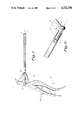
- FIG. 2 is an enlarged perspective view of the distal end of the instrument in operation.
- FIG. 3 is a side view of the preferred embodiment of the present invention.
- FIG. 4 is a side view of the shaft member of the present invention.
- FIG. 5 is a perspective view of the end of the shaft of FIG. 4 viewed along the line AA.
- FIG. 6 is a perspective view partially cut away of the device of FIG. 3 viewed along the line BB.
- FIG. 1 there is shown the forceps of the preferred embodiment of the present invention. Specifically there is shown a paired handle member 12 and 14 arranged to be held within the human hand and pulled together in the direction of the arrow 16 much in the same manner as a pair of pliers. This handle pair is arranged to pivot about the axis 18 and each is arranged as shown in the drawing to support and actuate the barrel and shaft cutting mechanism as more fully described below.
- a squeezing force on the paired handle members closes the handles in the direction of the arrow 16, and concurrently compresses the intermediate spring 20 located between the handle pair. This generates a returning force to return the handles to their starting position as shown in FIG. 3.
- the return spring is typically of spring steel made of distinct and separate members, each rigidly attached to respective individual handle members at the lower extremity 22 and 23 respectively, while being hingedly interlocked at the intermediate contacting point 24.
- a barrel member 26 comprised of a cylindrical tube having external threads 28 at its point of attachment to the handle, and having at its other extremity a honed edge 30 (more clearly shown in FIG. 6) for cutting bone pressed thereagainst.
- a honed edge 30 (more clearly shown in FIG. 6) for cutting bone pressed thereagainst.
- the upper edge is honed for cutting with the lower edge 31 being angled away from the end to avoid contact with the reciprocating mechanisms.
- a shaft member pivotally attached at axis 32 to said second handle member and arranged to selectively protrude from said barrel at its other extremity.
- This shaft member (FIG. 4) is comprised of a first attachment portion 34 for connection to the pivot mount at the handle, and a force transmission portion 36 for transmitting the force of the handle leverage mechanism remotely to the site of the bone cutting at the distal end of the barrel.
- a bone cutting and trapping portion comprised of a contoured plate 38 mounted transversely to the distal end of the shaft. This plate is shown with increased thickness in the vicinity of its attachment to the shaft to resist breakage.
- a cavity portion 40 (see FIG.
- a sealing portion 42 is provided to close the gap between the barrel and the shaft as the shaft end is drawn into the barrel. This sealing portion acts to maintain the barrel free of debris and serves to eject bone fragment following a cutting sequence.
- FIG. 2 In operation (see FIG. 2) there is shown a bone segment 52 with an unsevered portion 54 trapped between the shaft and plate 56 and the honed edge of the barrel 58. As the shaft is drawn towards the barrel, severed bone 60 is captured within the barrel. Once the stroke has been completed the forceps are removed from the cutting site, inverted, and the shaft extended from the barrel to facilitate deposit of the severed bone into the proper receptacle.
- an improved forcep or rongeur having a jaw mechanism comprised of a barrel member having a honed cutting edge on one extremity thereof and having a shaft member located within and arranged for reciprocal motion.
- a plate member attached at one extremity to trap bone against the cutting edge.
- a lever mechanism is provided having paired handle levers joined by a pivot and having the barrel and shaft members attached to the handle levers between the handle portion and the pivot.
- On the shaft member there is further provided a cavity arranged to slide within the barrel progressively as the cutting operation proceeds, gradually drawing severed bone within the capturing cavity.
Abstract
Description
Claims (4)
Priority Applications (1)
| Application Number | Priority Date | Filing Date | Title |
|---|---|---|---|
| US06/560,210 US4722338A (en) | 1983-12-12 | 1983-12-12 | Medical instrument for removing bone |
Applications Claiming Priority (1)
| Application Number | Priority Date | Filing Date | Title |
|---|---|---|---|
| US06/560,210 US4722338A (en) | 1983-12-12 | 1983-12-12 | Medical instrument for removing bone |
Publications (1)
| Publication Number | Publication Date |
|---|---|
| US4722338A true US4722338A (en) | 1988-02-02 |
Family
ID=24236819
Family Applications (1)
| Application Number | Title | Priority Date | Filing Date |
|---|---|---|---|
| US06/560,210 Expired - Lifetime US4722338A (en) | 1983-12-12 | 1983-12-12 | Medical instrument for removing bone |
Country Status (1)
| Country | Link |
|---|---|
| US (1) | US4722338A (en) |
Cited By (32)
| Publication number | Priority date | Publication date | Assignee | Title |
|---|---|---|---|---|
| US5108401A (en) * | 1991-04-12 | 1992-04-28 | New York Society For The Relief Of The Ruptured And Crippled, Maintaining The Hospital For Special Surgery | Patella cutting clamp |
| EP0541930A1 (en) * | 1991-10-17 | 1993-05-19 | Acufex Microsurgical Inc. | Transmission link for use in surgical instruments |
| US5273519A (en) * | 1990-11-02 | 1993-12-28 | Tibor Koros | Bongeur surgical instrument |
| US5439464A (en) * | 1993-03-09 | 1995-08-08 | Shapiro Partners Limited | Method and instruments for performing arthroscopic spinal surgery |
| WO1996014799A1 (en) | 1994-11-10 | 1996-05-23 | Michelson Gary K | Improved surgical rongeur |
| US5549636A (en) * | 1994-10-05 | 1996-08-27 | Li Medical Technologies Inc. | Surgical grasper with articulated fingers |
| US5597640A (en) * | 1992-10-09 | 1997-01-28 | Signode Corporation | Oriented plastic strap |
| US5683406A (en) * | 1995-09-29 | 1997-11-04 | Maxilon Laboratories, Llc | Apparatus and method for harvesting bone |
| US5766177A (en) * | 1996-04-02 | 1998-06-16 | Oceaneering International, Inc. | Rongeur |
| US5851214A (en) * | 1994-10-07 | 1998-12-22 | United States Surgical Corporation | Surgical instrument useful for endoscopic procedures |
| US5873886A (en) * | 1995-04-04 | 1999-02-23 | United States Surgical Corporation | Surgical cutting apparatus |
| US5879365A (en) * | 1995-04-04 | 1999-03-09 | United States Surgical Corporation | Surgical cutting apparatus |
| US5925050A (en) * | 1997-08-15 | 1999-07-20 | The University Of Iowa Research Foundation | Self-clearing bone biting instrument |
| US6200320B1 (en) | 1989-04-24 | 2001-03-13 | Gary Karlin Michelson | Surgical rongeur |
| US6375663B1 (en) | 1999-03-17 | 2002-04-23 | Maxilon Laboratories, Inc. | Bone grafting material |
| AU2002300799B9 (en) * | 1994-11-10 | 2003-02-20 | Gary Karlin Michelson | Improved Surgical Rongeur |
| US20030187450A1 (en) * | 2001-10-10 | 2003-10-02 | Agbodoe Victor Banford | Rongeur with detachable crossbar |
| US6638280B2 (en) | 2001-10-10 | 2003-10-28 | Codman & Shurtleff, Inc. | Rongeur with drainage |
| US6685710B2 (en) | 2001-10-10 | 2004-02-03 | Codman & Shurtleff, Inc. | Rongeur with detachable crossbar |
| US6755837B2 (en) | 2002-09-23 | 2004-06-29 | Maxilon Laboratories, Inc. | Apparatus and method for harvesting bone |
| US20040215343A1 (en) * | 2000-02-28 | 2004-10-28 | Stephen Hochschuler | Method and apparatus for treating a vertebral body |
| US20060149379A1 (en) * | 2000-07-21 | 2006-07-06 | Spineology, Inc. | Expandable porous mesh bag device and methods of use for reduction, filling, fixation and supporting of bone |
| WO2008099187A3 (en) * | 2007-02-15 | 2008-10-23 | Depuy Int Ltd | A tool for forming a cavity within a bone |
| US20090054898A1 (en) * | 2007-03-26 | 2009-02-26 | Joe Gleason | Articulating Shaper |
| US20100152855A1 (en) * | 2000-07-21 | 2010-06-17 | Kuslich Stephen D | Expandable porous mesh bag device and methods of use for reduction, filling, fixation and supporting of bone |
| US20100312265A1 (en) * | 2009-06-06 | 2010-12-09 | Martin Oberlaender | Medical punch |
| US9095345B2 (en) | 2012-03-06 | 2015-08-04 | Linares Medical Devices, Llc | Tissue and bone graft removal device |
| WO2017197057A1 (en) | 2016-05-11 | 2017-11-16 | H & M Innovations, Llc | Improvements in collecting and harvesting cut bone from rongeur |
| US9867626B2 (en) | 2012-08-03 | 2018-01-16 | Boss Instruments Ltd., Inc. | Push button Rongeur |
| US10092299B2 (en) | 2015-04-16 | 2018-10-09 | Steribite, LLC | Disposable kerrison rongeur |
| US10507027B2 (en) | 2012-08-03 | 2019-12-17 | Boss Instruments, Ltd., Inc. | Push button rongeur |
| US10925618B2 (en) | 2015-04-16 | 2021-02-23 | Steribite, LLC | Rongeur with a disposable attribute |
Citations (11)
| Publication number | Priority date | Publication date | Assignee | Title |
|---|---|---|---|---|
| DE230503C (en) * | ||||
| US571040A (en) * | 1896-11-10 | Bone-forceps | ||
| US988939A (en) * | 1909-11-30 | 1911-04-04 | William H Hudson | Surgical forceps. |
| US1002826A (en) * | 1911-04-06 | 1911-09-12 | Allen De Vilbiss | Bone-forceps. |
| US1040523A (en) * | 1912-01-19 | 1912-10-08 | Allen De Vilbiss | Bone-forceps or the like. |
| US1663761A (en) * | 1927-02-07 | 1928-03-27 | George A Johnson | Surgical instrument |
| US3752161A (en) * | 1971-08-02 | 1973-08-14 | Minnesota Mining & Mfg | Fluid operated surgical tool |
| EP0010321A1 (en) * | 1978-10-19 | 1980-04-30 | Renzo Dr. Brun Del Re | Device for the single-handed operation of a biopsy instrument |
| US4201213A (en) * | 1978-01-30 | 1980-05-06 | Codman & Shurtleff, Inc. | Surgical tool |
| US4316468A (en) * | 1977-08-05 | 1982-02-23 | Charles H. Klieman | Surgical stapler |
| US4574803A (en) * | 1979-01-19 | 1986-03-11 | Karl Storz | Tissue cutter |
-
1983
- 1983-12-12 US US06/560,210 patent/US4722338A/en not_active Expired - Lifetime
Patent Citations (11)
| Publication number | Priority date | Publication date | Assignee | Title |
|---|---|---|---|---|
| DE230503C (en) * | ||||
| US571040A (en) * | 1896-11-10 | Bone-forceps | ||
| US988939A (en) * | 1909-11-30 | 1911-04-04 | William H Hudson | Surgical forceps. |
| US1002826A (en) * | 1911-04-06 | 1911-09-12 | Allen De Vilbiss | Bone-forceps. |
| US1040523A (en) * | 1912-01-19 | 1912-10-08 | Allen De Vilbiss | Bone-forceps or the like. |
| US1663761A (en) * | 1927-02-07 | 1928-03-27 | George A Johnson | Surgical instrument |
| US3752161A (en) * | 1971-08-02 | 1973-08-14 | Minnesota Mining & Mfg | Fluid operated surgical tool |
| US4316468A (en) * | 1977-08-05 | 1982-02-23 | Charles H. Klieman | Surgical stapler |
| US4201213A (en) * | 1978-01-30 | 1980-05-06 | Codman & Shurtleff, Inc. | Surgical tool |
| EP0010321A1 (en) * | 1978-10-19 | 1980-04-30 | Renzo Dr. Brun Del Re | Device for the single-handed operation of a biopsy instrument |
| US4574803A (en) * | 1979-01-19 | 1986-03-11 | Karl Storz | Tissue cutter |
Cited By (55)
| Publication number | Priority date | Publication date | Assignee | Title |
|---|---|---|---|---|
| US20030216740A1 (en) * | 1989-04-24 | 2003-11-20 | Gary Karlin Michelson | Method for using a surgical rongeur |
| US6200320B1 (en) | 1989-04-24 | 2001-03-13 | Gary Karlin Michelson | Surgical rongeur |
| US7922723B2 (en) | 1989-04-24 | 2011-04-12 | Gary Karlin Michelson | Method for using a surgical rongeur |
| US6695849B2 (en) | 1989-04-24 | 2004-02-24 | Gary Karlin Michelson | Surgical rongeur |
| US6575977B1 (en) | 1989-04-24 | 2003-06-10 | Gary Karlin Michelson | Surgical rongeur |
| US20040186499A1 (en) * | 1989-08-28 | 2004-09-23 | Gary Karlin Michelson | Surgical rongeur |
| US20060149271A1 (en) * | 1989-08-28 | 2006-07-06 | Michelson Gary K | Method for cutting bone or cartilage with a rongeur |
| US7297147B2 (en) | 1989-08-28 | 2007-11-20 | Gary Karlin Michelson | Method for cutting bone or cartilage with a rongeur |
| US7011663B2 (en) | 1989-08-28 | 2006-03-14 | Gary Karlin Michelson | Surgical rongeur having a removable storage member |
| US5273519A (en) * | 1990-11-02 | 1993-12-28 | Tibor Koros | Bongeur surgical instrument |
| US5108401A (en) * | 1991-04-12 | 1992-04-28 | New York Society For The Relief Of The Ruptured And Crippled, Maintaining The Hospital For Special Surgery | Patella cutting clamp |
| EP0838198A1 (en) * | 1991-10-17 | 1998-04-29 | Smith & Nephew, Inc. | Transmission link for use in surgical instruments |
| EP0541930A1 (en) * | 1991-10-17 | 1993-05-19 | Acufex Microsurgical Inc. | Transmission link for use in surgical instruments |
| US5597640A (en) * | 1992-10-09 | 1997-01-28 | Signode Corporation | Oriented plastic strap |
| US5439464A (en) * | 1993-03-09 | 1995-08-08 | Shapiro Partners Limited | Method and instruments for performing arthroscopic spinal surgery |
| US20110190773A1 (en) * | 1993-08-18 | 2011-08-04 | Gary Karlin Michelson | Surgical rongeur |
| US8241290B2 (en) | 1993-08-18 | 2012-08-14 | Michelson Gary K | Surgical rongeur |
| US5549636A (en) * | 1994-10-05 | 1996-08-27 | Li Medical Technologies Inc. | Surgical grasper with articulated fingers |
| US5851214A (en) * | 1994-10-07 | 1998-12-22 | United States Surgical Corporation | Surgical instrument useful for endoscopic procedures |
| AU2002300799B9 (en) * | 1994-11-10 | 2003-02-20 | Gary Karlin Michelson | Improved Surgical Rongeur |
| WO1996014799A1 (en) | 1994-11-10 | 1996-05-23 | Michelson Gary K | Improved surgical rongeur |
| EP1525853A2 (en) | 1994-11-10 | 2005-04-27 | Gary Karlin Michelson | Improved surgical rongeur |
| AU2002300799B2 (en) * | 1994-11-10 | 2004-08-05 | Gary Karlin Michelson | Improved Surgical Rongeur |
| US5879365A (en) * | 1995-04-04 | 1999-03-09 | United States Surgical Corporation | Surgical cutting apparatus |
| US5873886A (en) * | 1995-04-04 | 1999-02-23 | United States Surgical Corporation | Surgical cutting apparatus |
| US5683406A (en) * | 1995-09-29 | 1997-11-04 | Maxilon Laboratories, Llc | Apparatus and method for harvesting bone |
| WO1999065396A1 (en) * | 1996-04-02 | 1999-12-23 | Aesculap, Inc. | Rongeur |
| US5766177A (en) * | 1996-04-02 | 1998-06-16 | Oceaneering International, Inc. | Rongeur |
| US5925050A (en) * | 1997-08-15 | 1999-07-20 | The University Of Iowa Research Foundation | Self-clearing bone biting instrument |
| US6375663B1 (en) | 1999-03-17 | 2002-04-23 | Maxilon Laboratories, Inc. | Bone grafting material |
| US7931689B2 (en) | 2000-02-28 | 2011-04-26 | Spineology Inc. | Method and apparatus for treating a vertebral body |
| US20040215343A1 (en) * | 2000-02-28 | 2004-10-28 | Stephen Hochschuler | Method and apparatus for treating a vertebral body |
| US20100152855A1 (en) * | 2000-07-21 | 2010-06-17 | Kuslich Stephen D | Expandable porous mesh bag device and methods of use for reduction, filling, fixation and supporting of bone |
| US20100268231A1 (en) * | 2000-07-21 | 2010-10-21 | Spineology, Inc. | Expandable porous mesh bag device and methods of use for reduction, filling, fixation and supporting of bone |
| US20060149379A1 (en) * | 2000-07-21 | 2006-07-06 | Spineology, Inc. | Expandable porous mesh bag device and methods of use for reduction, filling, fixation and supporting of bone |
| US20030187450A1 (en) * | 2001-10-10 | 2003-10-02 | Agbodoe Victor Banford | Rongeur with detachable crossbar |
| US6638280B2 (en) | 2001-10-10 | 2003-10-28 | Codman & Shurtleff, Inc. | Rongeur with drainage |
| US6685710B2 (en) | 2001-10-10 | 2004-02-03 | Codman & Shurtleff, Inc. | Rongeur with detachable crossbar |
| US6991633B2 (en) * | 2001-10-10 | 2006-01-31 | Codman & Shurtleff, Inc. | Rongeur with detachable crossbar |
| US20060064102A1 (en) * | 2002-09-23 | 2006-03-23 | Ebner Peter R | Apparatus and method for harvesting bone |
| US6755837B2 (en) | 2002-09-23 | 2004-06-29 | Maxilon Laboratories, Inc. | Apparatus and method for harvesting bone |
| US8343158B2 (en) | 2007-02-15 | 2013-01-01 | Depuy International Limited | Tool for forming a cavity within a bone |
| US20100094296A1 (en) * | 2007-02-15 | 2010-04-15 | Alec Paul Birkbeck | Tool for forming a cavity within a bone |
| WO2008099187A3 (en) * | 2007-02-15 | 2008-10-23 | Depuy Int Ltd | A tool for forming a cavity within a bone |
| US20090054898A1 (en) * | 2007-03-26 | 2009-02-26 | Joe Gleason | Articulating Shaper |
| US20100312265A1 (en) * | 2009-06-06 | 2010-12-09 | Martin Oberlaender | Medical punch |
| US8702740B2 (en) * | 2009-06-06 | 2014-04-22 | Karl Storz Gmbh & Co. Kg | Medical punch |
| US9095345B2 (en) | 2012-03-06 | 2015-08-04 | Linares Medical Devices, Llc | Tissue and bone graft removal device |
| US9883868B2 (en) | 2012-03-06 | 2018-02-06 | Linares Medical Devices, Llc | Tissue and bone graft removal device |
| US9867626B2 (en) | 2012-08-03 | 2018-01-16 | Boss Instruments Ltd., Inc. | Push button Rongeur |
| US10507027B2 (en) | 2012-08-03 | 2019-12-17 | Boss Instruments, Ltd., Inc. | Push button rongeur |
| US11317926B2 (en) | 2012-08-03 | 2022-05-03 | Boss Instruments, Ltd., Inc. | Push button rongeur |
| US10092299B2 (en) | 2015-04-16 | 2018-10-09 | Steribite, LLC | Disposable kerrison rongeur |
| US10925618B2 (en) | 2015-04-16 | 2021-02-23 | Steribite, LLC | Rongeur with a disposable attribute |
| WO2017197057A1 (en) | 2016-05-11 | 2017-11-16 | H & M Innovations, Llc | Improvements in collecting and harvesting cut bone from rongeur |
Similar Documents
| Publication | Publication Date | Title |
|---|---|---|
| US4722338A (en) | Medical instrument for removing bone | |
| US4733663A (en) | Medical instrument for removing bone | |
| US3328876A (en) | Surgical suture extractor | |
| US5275615A (en) | Medical instrument having gripping jaws | |
| US5925050A (en) | Self-clearing bone biting instrument | |
| US5254129A (en) | Arthroscopic resector | |
| US5250056A (en) | Forceps-type surgical instrument | |
| EP1326545B1 (en) | Surgical tool mechanism | |
| US5919206A (en) | Surgical tool | |
| US5746216A (en) | Endoscopic multiple sample bioptome with enhanced biting action | |
| US5582618A (en) | Surgical cutting instrument | |
| EP0773001A2 (en) | Improved latch mechanism for surgical instruments | |
| EP0830845A1 (en) | Ultrasonic dissector | |
| US5584855A (en) | Safety surgical grasping forceps | |
| CA2500567A1 (en) | Angled surgical fastener apparatus | |
| JPH05184588A (en) | Surgical suction clamp | |
| EP0068046B1 (en) | Surgical ligating instrument | |
| EP0244491B1 (en) | Medical instrument for removing bone | |
| US4020848A (en) | Ear lobe piercing apparatus | |
| US5357677A (en) | Toe nail clipper apparatus | |
| US5047037A (en) | Suture removing instrument | |
| US6102919A (en) | Apparatus and method for removing parasites | |
| EP0243803B1 (en) | Medical instrument for removing bone tissue | |
| CA2255227A1 (en) | Citrus fruit segmenter | |
| WO2004024006A1 (en) | Suture apparatus |
Legal Events
| Date | Code | Title | Description |
|---|---|---|---|
| AS | Assignment |
Owner name: FARLEY, DANIEL, 236 B GEORGE STREET, BARRINGTON, I Free format text: ASSIGNMENT OF ASSIGNORS INTEREST.;ASSIGNOR:WRIGHT, DAVID W.;REEL/FRAME:004507/0391 Effective date: 19851203 |
|
| AS | Assignment |
Owner name: DANIEL FARLEY Free format text: ASSIGNMENT OF ASSIGNORS INTEREST.;ASSIGNORS:WRIGHT, DALE W.;WRIGHT, DAVID W.;REEL/FRAME:004697/0126 Effective date: 19860113 |
|
| STCF | Information on status: patent grant |
Free format text: PATENTED CASE |
|
| FEPP | Fee payment procedure |
Free format text: PAT HLDR NO LONGER CLAIMS SMALL ENT STAT AS INDIV INVENTOR (ORIGINAL EVENT CODE: LSM1); ENTITY STATUS OF PATENT OWNER: SMALL ENTITY Free format text: PAYOR NUMBER ASSIGNED (ORIGINAL EVENT CODE: ASPN); ENTITY STATUS OF PATENT OWNER: SMALL ENTITY |
|
| FPAY | Fee payment |
Year of fee payment: 4 |
|
| FPAY | Fee payment |
Year of fee payment: 8 |
|
| FEPP | Fee payment procedure |
Free format text: PAT HOLDER CLAIMS SMALL ENTITY STATUS - SMALL BUSINESS (ORIGINAL EVENT CODE: SM02); ENTITY STATUS OF PATENT OWNER: SMALL ENTITY |
|
| FPAY | Fee payment |
Year of fee payment: 12 |