US4583117A - Stereoscopic video camera - Google Patents
Stereoscopic video camera Download PDFInfo
- Publication number
- US4583117A US4583117A US06/631,894 US63189484A US4583117A US 4583117 A US4583117 A US 4583117A US 63189484 A US63189484 A US 63189484A US 4583117 A US4583117 A US 4583117A
- Authority
- US
- United States
- Prior art keywords
- video
- field
- camera system
- camera
- stereoscopic camera
- Prior art date
- Legal status (The legal status is an assumption and is not a legal conclusion. Google has not performed a legal analysis and makes no representation as to the accuracy of the status listed.)
- Expired - Fee Related
Links
- 239000002131 composite material Substances 0.000 claims description 10
- 230000003287 optical effect Effects 0.000 claims description 5
- 230000005540 biological transmission Effects 0.000 abstract 1
- 238000010586 diagram Methods 0.000 description 12
- 238000012986 modification Methods 0.000 description 4
- 230000004048 modification Effects 0.000 description 4
- 230000003111 delayed effect Effects 0.000 description 3
- 230000000694 effects Effects 0.000 description 2
- 238000006243 chemical reaction Methods 0.000 description 1
- 230000006835 compression Effects 0.000 description 1
- 238000007906 compression Methods 0.000 description 1
- 230000004927 fusion Effects 0.000 description 1
- 238000003780 insertion Methods 0.000 description 1
- 230000037431 insertion Effects 0.000 description 1
- 239000007787 solid Substances 0.000 description 1
- 230000001960 triggered effect Effects 0.000 description 1
Images


Classifications
-
- H—ELECTRICITY
- H04—ELECTRIC COMMUNICATION TECHNIQUE
- H04N—PICTORIAL COMMUNICATION, e.g. TELEVISION
- H04N13/00—Stereoscopic video systems; Multi-view video systems; Details thereof
- H04N13/30—Image reproducers
- H04N13/332—Displays for viewing with the aid of special glasses or head-mounted displays [HMD]
- H04N13/341—Displays for viewing with the aid of special glasses or head-mounted displays [HMD] using temporal multiplexing
-
- H—ELECTRICITY
- H04—ELECTRIC COMMUNICATION TECHNIQUE
- H04N—PICTORIAL COMMUNICATION, e.g. TELEVISION
- H04N13/00—Stereoscopic video systems; Multi-view video systems; Details thereof
- H04N13/20—Image signal generators
- H04N13/204—Image signal generators using stereoscopic image cameras
- H04N13/239—Image signal generators using stereoscopic image cameras using two 2D image sensors having a relative position equal to or related to the interocular distance
-
- H—ELECTRICITY
- H04—ELECTRIC COMMUNICATION TECHNIQUE
- H04N—PICTORIAL COMMUNICATION, e.g. TELEVISION
- H04N13/00—Stereoscopic video systems; Multi-view video systems; Details thereof
- H04N13/10—Processing, recording or transmission of stereoscopic or multi-view image signals
Definitions
- This invention relates to an improved stereoscopic video camera system, and more particularly to one which has a great deal of compatibility with the existing commercial television infrastructure requiring only minor modification to existing video cameras.
- left and right cameras which are modified to run at 120 Hz are utilized.
- the cameras When used with the appropriate switching electronics, the cameras produce the "over-and-under" format of 131.25 lines above, and 131.25 lines below. Cameras which produce 120 fields per second are uncommon and, generally speaking, not provided by manufacturers.
- cameras In order to produce the needed left-right-left-right sequence of fields in one stereoscopic frame within one thirtieth of a second, for a flickerless image, cameras need to be modified for a field rate higher than the usual 60 Hz. This modification is generally simpler for black and white than color cameras, since certain color cameras, especially those with a single tube, are difficult to operate at 120 Hz while producing a good color signal. Such modifications entail the significant expense of conversion and calibration.
- Another object of the present invention is to provide an improved stereoscopic video camera which produces 120 video fields per second.
- Another object of the present invention is to provide an improved stereoscopic video camera system which utilizes standard video cameras with only minor modifications.
- Another object of the invention is to provide an improved stereoscopic video camera system which provides an "over-and-under” field format.
- standard 60 Hz left and a right video cameras are employed. However, only one-half of the horizontal scan lines, scanned consecutively and containing a complete picture, are utilized from each camera.
- the scan lines which provide information from the central half of the camera tube (or solid state pickup) light sensitive surface are employed. Only the image which is scanned in the central half of each light sensitive surface of each camera is utilized. In otherwords, the middle 131.25 lines or half the number of lines scanned in each field are employed, and they contain a complete left or right picture view. The other 131.25 lines are unused.
- Electronic combining means external to the respective left and right video cameras, then combine the left and right camera views, each containing one-half of the normal number of horizontal scans, into a single field in the over-and-under format described in co-pending patent application U.S. Pat. No. 4,523,226.
- each video camera is altered so that only one-half of the normal number of horizontal lines scan the light sensitive portion.
- each camera is altered so that only one-half of the normal number of horizontal lines scan the light sensitive portion.
- it is only necessary to double the slope of the horizontal scan lines by increasing the slope of the vertical sweep. With some cameras this can be done by merely adjusting a gain control knob. But even if this option is not available, it is a simple matter to modify the left and right video cameras to increase the gain.
- FIG. 1A is a schematic illustration of the first two subfields produced by the left and right stereoscopic cameras of the present invention
- FIG. 1B is a schematic diagram of the second two subfields produced by the left and right stereoscopic cameras of the present invention.
- FIG. 2A shows the over-and-under stereoscopic video format from the stereoscopic camera system of the present invention as it appears on an unmodified 60 Hz monitor; and FIG. 2B shows the present stereoscopic video format as it appears on a 120 Hz monitor.
- FIG. 3A is a block diagram of the version of the present stereoscopic video camera system described in the patent application cited above; and FIG. 3B is a block diagram of another version of the present stereoscopic video camera system, with the camera optical system employing cylindrical lenses.
- FIG. 4A schematically illustrates the light sensitive surface of the pickup device of a left video camera showing only the central portion scan lines being utilized
- FIG. 4B schematically illustrates the light sensitive surface of the pickup device of a right video camera showing only the central portion scan lines being utilized
- FIG. 4C shows the light sensitive surface of the pickup device of a left video camera after increasing the slop of the horizontal scan lines so that only half the usual number of scan lines traverse this light sensitive surface
- FIG. 4D shows the light sensitive surface of the pickup device of a right video camera modified in the same manner.
- FIG. 5 is a timing diagram showing the appropriate delay for the vertical sync for each camera in relationship to the composite output video signal.
- FIG. 6 is a timing diagram of the left and right camera vertical sync and video signals.
- FIG. 7 is a block schematic diagram of the signal combining circuits of FIG. 3A and 3B.
- FIG. 8 consisting of FIGS. 8A, 8B, 8C, 8D and 8E, is a detailed schematic of the block diagram of FIG. 7.
- FIG. 9 is a schematic diagram of a part of the circuit of a Sony DXC-1800 single tube color camera.
- FIG. 10 is a timing diagram for a modified camera system configuration.
- FIG. 11A is a signal diagram for the plate voltage of an unmodified Sony DXC-1800 color camera
- FIG. 11B shows the plate voltage for the Sony DXC-1800 color camera modified in accordance with the wave form shown in FIG. 10.
- FIGS. 1A and 1B show four successive subfields which make up a pair of video fields 10 and 12, which in turn make up a stereoscopic frame in accordance with the "over-and-under" format described in U.S. Patent Application U.S. Pat. No. 4,523,226.
- Each of the four subfields L 1 , R 1 , L 2 , and R 2 contain 131.25 lines.
- FIGS. 1A and 1B are essentially timing diagrams, with time in the vertical axis. The vertical blanking areas have been omitted in these schematic representations for didactic purposes.
- L 1 , R 1 , L 2 , R 2 make up one stereoscopic frame.
- L 1 and L 2 form an interlaced pair of fields, and R 1 and R 2 form another when displayed on a 120 Hz monitor, as explained in U.S. Pat. No. 4,523,226.
- subfields in the stereoscopic "over-and-under" format with a quarter line “leftover” produce a four-fold interlace.
- alternate similar "eyed" subfields, as L 1 , and L 2 have a two-fold interlace.
- the fields are presented L 1 , R 1 , L 2 , R 2 , and not L 1 , L 2 , R 1 , R 2 . If L 1 and L 2 followed each other directly, these subfields would not be properly interlaced.
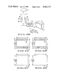
- FIG. 3A shows a camera system 14 as disclosed in U.S. Patent Application U.S. Pat. No. 4,523,226.
- Left and right stereoscopic cameras 18 and 19 with lenses 20 and 21 respectively, are converged along extended lens axes 16 and 17 on object 15.
- Each operates at 120 Hz. vertical scan rate. Accordingly, each subfield has 131.25 horizontal lines.
- the subfields are switched alternately by combining means 22 to form an output video signal with the "over-and-under format" as shown in FIG. 2A and displayed on monitor 23 display screen 24.
- the fields are viewed through appropriate selection devices, in this case electro-optical shutters 26 and 27 located in spectacles 25. Shutters 26 and 27 are in synchronization with the subfield rate. The observer views a flickerless stereoscopic image through spectacles 25.
- FIG. 2A When observed on a standard 60 Hz monitor display screen, the image appears as shown in FIG. 2A. Assume that the picture view is that of a circle.
- the display screen 24 has an image of an elipse whose horizontal axis is D in each subfield.
- the images of circles are anamorphically compressed in the vertical direction. Accordingly, the vertical axis of the elipse shown in subfield 32 (L 1 ) is D/2, as it is for the elipse shown in subfield 33.
- FIG. 2A shows subfield L 1 in the upper half of the image, and subfield R 1 in the bottom half of the 60 Hz image. It should be understood that the description given above and to follow could just as well be given in terms of an upper right image and a lower left image.
- the vertical blanking area 35 separates the two subfields 32 and 33.
- the usual 60 Hz blanking area is shown as 35' in FIG. 2A.
- Added blanking area 35 is the same interval as 35', the usual NTSC field blanking area.
- the screen 24' when displayed on a 120 Hz monitor, as described in co-pending patent application U.S. Pat. No. 4,523,226 the screen 24' provides two images (circles) which appear to be nearly superimposed.
- the images of the left and right circles are shown in subfields 32' and 33', respectively.
- the images in these subfields are alternately presented so rapidly in sequence that when viewed without the aide of selection device 25 the images appear to be superimposed.
- subfield 32' is visible through electro-optical shutter 26 while subfield 33' is occluded, and vice versa. This produces a stereoscopic effect to the viewer.
- cameras 18 and 19 operate at 60 Hz, rather than 120 Hz as will now be explained.
- Two examples of camera systems are described to produce an undistorted image on a 120 Hz monitor screen of the usual aspect ratio, utilizing 60 Hz cameras.
- cylindrical lens elements 40 and 41 are incorporated with lenses 20' and 21' of each of the two 60 Hz cameras 18' and 19' respectively.
- the cylindrical lenses produce anamorphically compressed images in the vertical direction, to produce subfields 32 and 33 in FIG. 2A.
- the compressed images from the cylindrical lenses 40 and 41 are centered on the light sensitive portion of the respective cameras 18' and 19'.
- FIGS. 4A and 4B show the light sensitive surfaces 42 of the pick-up devices of the left and right cameras 18' and 19'.
- the dimension h is the horizontal extent of the image
- v is the vertical dimension of the image. Accordingly, the aspect ratio is given as h/v. In the case of the usual video system, this is 1.3:1.
- cameras 18' and 19' operating at 60 Hz, and modified as described above have their video outputs switched through combining means 22' and are displayed on a 60 Hz monitor, the images are anamorphically compressed in the vertical direction by a factor of two as shown in FIG. 2A.
- a geometrically undistorted stereoscopic image is displayed when viewed through selection device 25 as shown in FIG. 2B.
- the display shown in FIG. 2A represents a field of NTSC video having a duration of 1/60 sec., which is a video display of a video frame of the output of the combining circuits 22'.
- the standard vertical interval 35' coupled with picture 32 form the first portion or subfield of a stereoscopic pair.
- Added vertical interval 35 and picture 33 form the second portion or subfield of the pair.
- the first image must originate in one camera and the second in the other. They will arbitrarily be called left for the first image 32 and right for the second image 33. No loss of generality occurs if the first camera is right and the second left.
- the first 131.25 horizontal lines come from camera 18' and the combining means 22', comprising a sync generator and switching circuit, then switches to the second camera 19' .
- the circuit 22' adds the blanking area 35 to the start of the second subfield 30.
- the 131.25 horizontal lines from each camera must be centered on both the horizontal and vertical optical axes of the respective lenses 20' and 21'. If the central lines are used without increasing the sweep vertical amplitude, the pattern of FIG. 4A and 4B results. On the other hand, if the raster height is increased, by increasing the sweep vertical amplitude sufficiently to double the horizontal sweep slope, the result is illustrated in FIGS. 4C and 4D. This achieves the desired 2:1 anamorphosis without an anamorphic lens.
- the vertical sync signal from combining circuit 22' to each camera is delayed a specified amount of time, as illustrated in FIGS. 5 and 6.
- the left hand column in FIG. 5 represents the output from the combiner circuit 22'. Outputs from the left and right cameras are illustrated in the middle and right hand columns, respectively.
- Circuit 22' provides vertical sync signals 55 to left camera 18' and vertical sync signals 56 to right camera 19. It also provides the output vertical sync signals 57 at the beginning of each "over-and-under" field.
- field 91 having the composite "over-and-under" format is made up of a left hand image L 2 taken from the central half 62 of field 60, the photo sensitive area 42 of the left camera 18', as well as a right hand image R 2 taken from the central half 72 of field 70, from the right camera 19'.
- Field 60 must start about 1/4 of a field before composite field 91, so that the desired central part 62 starts and forms the upper half of field 91.
- field 70 must start about 1/4 field after the beginning of field 91 to form the bottom half of field 91.
- Combining circuit 22' generates all three sync signals 55, 56, and 57 to produce these results. All are produced using the same subcarrier generator and horizontal sync to keep all the signals phased together. Only the insertion point of the vertical sync pulses differ. The horizontal sync and blanking burst signals are omitted from FIGS. 5 and 6 for clarity. The end result is a composite video signal 140 that is compatible with existing standards such as NTSC.
- the combining and sync generator network 22' is shown in block form in FIG. 7 and in schematic form in FIG. 8.
- Master oscillator 306 operates at 14.3818 Hhz, 4 times NTSC burst frequency, and is divided to provide the subcarrier and the master sync generator clock.
- Master sync generator 303 utilizes a National MM5321 sync generator chip to create the master composite sync, burst and blanking signals.
- a line rate multiplier utilizes a phase locked loop circuit which serves as an 8 times multiplier from the H sync to create the 8H clock for the delay counter chains 304 and 305 respectively.
- the vertical index from the MM5321 sync chip starts the delay counters 304 and 305 and they count at 8 times H rate to provide a delay of 1/4 of the field period for counter 304 and 3/4 of the field period for counter 305.
- These delayed pulses reset slave sync generators 307 and 308 respectively, which provide all the signals needed for the left and right video cameras respectively.
- the two slave sync chips 307 and 308 are both National MM5321 circuits and share the master clock signal with master sync generator 303 and are thus always in syncronization.
- Master sync section 303 provides a subfield select signal to video switch 301 to select the correct camera as a non-composite video source in sync with slave sync generators 307 and 308.
- Blanker, mixer and amplifier 302 mixes the multiplexed noncomposite video from video switch 301 with the sync, color burst and blanking signals from master sync generator 303 to produce an NTSC compatible output composite video signal the "over-and-under" format.
- FIG. 9 is a schematic diagram of the vertical deflection pulse generator circuit of a Sony Model DXC-1800 single tube color camera. All that is required to provide the doubled slope of the horizontal scan lines is to change the following resistors:
- RV7 change from 10 Kohm to 47 Kohm
- RV6 change from 47 Kohm to 500 Kohm
- FIG. 10 illustrates the separate and combined output of cameras 18' and 19'.
- the entire photosensitive area 42 of each camera 18' and 19' is scanned in 8.33 milliseconds one-half the usual time of 16.67 milliseconds.
- FIGS. 11A and 11B show the change in voltages on the vertical deflection plates of the camera tube over time.
- the slope of the vertical sweep (FIG. 11A) is doubled (FIG. 11B) and thus the entire image is scanned in 1/2 the usual time.
- Each camera 18' and 19' scans the image in 131.25 lines after vertical sync.
- the first one-half of the field is provided by camera 18' and the second one-half is provided by camera 19' which is triggered by a delayed vertical sync.
- Each field is now comprised of first the left image and then the right image which is the desired "over and under" format.
- the Sony DXC-1800 single tube video camera is modified to produce the deflection shown in FIG. 11B by a simple change.
- the desired 2:1 vertical compression at 60 Hz is inherent because the camera scans the entire image in the time the 60 Hz display would only scan half the screen. Thus ordinary video lenses may be used on the cameras.
Abstract
Description
Claims (10)
Priority Applications (1)
| Application Number | Priority Date | Filing Date | Title |
|---|---|---|---|
| US06/631,894 US4583117A (en) | 1984-07-17 | 1984-07-17 | Stereoscopic video camera |
Applications Claiming Priority (1)
| Application Number | Priority Date | Filing Date | Title |
|---|---|---|---|
| US06/631,894 US4583117A (en) | 1984-07-17 | 1984-07-17 | Stereoscopic video camera |
Publications (1)
| Publication Number | Publication Date |
|---|---|
| US4583117A true US4583117A (en) | 1986-04-15 |
Family
ID=24533215
Family Applications (1)
| Application Number | Title | Priority Date | Filing Date |
|---|---|---|---|
| US06/631,894 Expired - Fee Related US4583117A (en) | 1984-07-17 | 1984-07-17 | Stereoscopic video camera |
Country Status (1)
| Country | Link |
|---|---|
| US (1) | US4583117A (en) |
Cited By (137)
| Publication number | Priority date | Publication date | Assignee | Title |
|---|---|---|---|---|
| US4858157A (en) * | 1985-03-13 | 1989-08-15 | Tokyo Kogaku Kikai Kabushiki Kaisha | Apparatus and method for determining the coordinates of a three-dimensional object |
| US4967268A (en) * | 1989-07-31 | 1990-10-30 | Stereographics | Liquid crystal shutter system for stereoscopic and other applications |
| US5007715A (en) * | 1988-03-10 | 1991-04-16 | U.S. Philips Corporation | Display and pick-up device for stereoscopic picture display |
| WO1991006184A1 (en) * | 1989-10-11 | 1991-05-02 | Reuben Hoppenstein | Method and apparatus for creating three-dimensional television or other multi-dimensional images |
| US5026151A (en) * | 1989-06-23 | 1991-06-25 | Mentor O & O, Inc. | Visual function tester with binocular vision testing |
| US5142357A (en) * | 1990-10-11 | 1992-08-25 | Stereographics Corp. | Stereoscopic video camera with image sensors having variable effective position |
| US5416510A (en) * | 1991-08-28 | 1995-05-16 | Stereographics Corporation | Camera controller for stereoscopic video system |
| US5428386A (en) * | 1992-08-24 | 1995-06-27 | Envision Medical Corporation | Remote 3D video camera system |
| US5515268A (en) * | 1992-09-09 | 1996-05-07 | Mitsubishi Denki Kabushiki Kaisha | Method of and system for ordering products |
| US5532777A (en) * | 1995-06-06 | 1996-07-02 | Zanen; Pieter O. | Single lens apparatus for three-dimensional imaging having focus-related convergence compensation |
| US5537144A (en) * | 1990-06-11 | 1996-07-16 | Revfo, Inc. | Electro-optical display system for visually displaying polarized spatially multiplexed images of 3-D objects for use in stereoscopically viewing the same with high image quality and resolution |
| US5553203A (en) * | 1990-09-26 | 1996-09-03 | Reveo, Inc. | Pixel data processing system and method for producing and graphically presenting spatially multiplexed images of 3-D objects for stereoscopic viewing thereof |
| US5572235A (en) * | 1992-11-02 | 1996-11-05 | The 3Do Company | Method and apparatus for processing image data |
| US5596693A (en) * | 1992-11-02 | 1997-01-21 | The 3Do Company | Method for controlling a spryte rendering processor |
| US5627582A (en) * | 1993-11-29 | 1997-05-06 | Canon Kabushiki Kaisha | Stereoscopic compression processing with added phase reference |
| EP0776738A2 (en) | 1992-01-21 | 1997-06-04 | Sri International | An endoscopic surgical instrument |
| US5752073A (en) * | 1993-01-06 | 1998-05-12 | Cagent Technologies, Inc. | Digital signal processor architecture |
| US5751341A (en) * | 1993-01-05 | 1998-05-12 | Vista Medical Technologies, Inc. | Stereoscopic endoscope system |
| US5786848A (en) * | 1993-07-13 | 1998-07-28 | Sony Corporation | Three-dimensional video signal generator and three-dimensional video display apparatus |
| US5807378A (en) * | 1995-06-07 | 1998-09-15 | Sri International | Surgical manipulator for a telerobotic system |
| US5810880A (en) * | 1995-06-07 | 1998-09-22 | Sri International | System and method for releasably holding a surgical instrument |
| US5828913A (en) * | 1995-06-06 | 1998-10-27 | Zanen; Pieter O. | Method for three dimensional measurement and imaging having focus-related convergence compensation |
| US5838389A (en) * | 1992-11-02 | 1998-11-17 | The 3Do Company | Apparatus and method for updating a CLUT during horizontal blanking |
| US5844717A (en) * | 1990-06-11 | 1998-12-01 | Reveo, Inc. | Method and system for producing micropolarization panels for use in micropolarizing spatially multiplexed images of 3-D objects during stereoscopic display processes |
| US5931832A (en) * | 1993-05-14 | 1999-08-03 | Sri International | Methods for positioning a surgical instrument about a remote spherical center of rotation |
| US5973726A (en) * | 1993-09-24 | 1999-10-26 | Canon Kabushiki Kaisha | Panoramic image processing apparatus |
| US6111598A (en) * | 1993-11-12 | 2000-08-29 | Peveo, Inc. | System and method for producing and displaying spectrally-multiplexed images of three-dimensional imagery for use in flicker-free stereoscopic viewing thereof |
| US6191772B1 (en) | 1992-11-02 | 2001-02-20 | Cagent Technologies, Inc. | Resolution enhancement for video display using multi-line interpolation |
| US6195205B1 (en) | 1991-12-18 | 2001-02-27 | Reveo, Inc. | Multi-mode stereoscopic imaging system |
| US6236428B1 (en) * | 1994-08-02 | 2001-05-22 | Canon Kabushiki Kaisha | Multi-eye image sensing and recording and reproduction apparatus |
| US6264665B1 (en) * | 1996-04-17 | 2001-07-24 | The Lions Eye Institute Of Western Australia Incorporated | System for ocular ultramicrosurgery |
| US20020113878A1 (en) * | 2000-07-13 | 2002-08-22 | Yoshiaki Iwai | Camera calibration device and method, and computer system |
| US6546208B1 (en) | 1999-11-22 | 2003-04-08 | Sl3D, Inc. | Stereoscopic telescope with camera |
| US6621921B1 (en) * | 1995-12-19 | 2003-09-16 | Canon Kabushiki Kaisha | Image processing apparatus |
| US20030174203A1 (en) * | 2000-07-19 | 2003-09-18 | Junichi Takeno | Image converter for providing flicker-free stereoscopic image based on top-down split frame sequential suitable for computer communications |
| US6640004B2 (en) * | 1995-07-28 | 2003-10-28 | Canon Kabushiki Kaisha | Image sensing and image processing apparatuses |
| US6643396B1 (en) | 1999-06-11 | 2003-11-04 | Emile Hendriks | Acquisition of 3-D scenes with a single hand held camera |
| US20040070823A1 (en) * | 2002-10-10 | 2004-04-15 | Radna Richard J. | Head-mount recording of three-dimensional stereo video images |
| US6731988B1 (en) | 1992-01-21 | 2004-05-04 | Sri International | System and method for remote endoscopic surgery |
| US20040145655A1 (en) * | 2002-12-02 | 2004-07-29 | Seijiro Tomita | Stereoscopic video image display apparatus and stereoscopic video signal processing circuit |
| US6772053B2 (en) | 1998-12-08 | 2004-08-03 | Visx, Incorporated | Aspects of a control system of a minimally invasive surgical apparatus |
| US6788999B2 (en) | 1992-01-21 | 2004-09-07 | Sri International, Inc. | Surgical system |
| US6819488B2 (en) | 2000-05-24 | 2004-11-16 | Pieter O. Zanen | Device for making 3-D images |
| US6850817B1 (en) | 1992-01-21 | 2005-02-01 | Sri International | Surgical system |
| US20050259179A1 (en) * | 2004-05-24 | 2005-11-24 | Jerry Lynn Robertson | Electro-optical shutter |
| US7015954B1 (en) | 1999-08-09 | 2006-03-21 | Fuji Xerox Co., Ltd. | Automatic video system using multiple cameras |
| US20060092273A1 (en) * | 1998-12-08 | 2006-05-04 | Intuitive Surgical, Inc. | Stereo imaging system and method for use in telerobotic systems |
| US20070239203A1 (en) * | 2002-12-06 | 2007-10-11 | Intuitive Surgical, Inc. | Flexible wrist for surgical tool |
| US20080108933A1 (en) * | 2006-06-30 | 2008-05-08 | Dao-Yi Yu | Methods, Systems and Apparatus for Relieving Pressure in an Organ |
| US7492476B1 (en) | 1999-11-23 | 2009-02-17 | Canon Kabushiki Kaisha | Image processing apparatus |
| USD616486S1 (en) | 2008-10-20 | 2010-05-25 | X6D Ltd. | 3D glasses |
| US20100149320A1 (en) * | 2008-11-17 | 2010-06-17 | Macnaughton Boyd | Power Conservation System for 3D Glasses |
| US20100194861A1 (en) * | 2009-01-30 | 2010-08-05 | Reuben Hoppenstein | Advance in Transmission and Display of Multi-Dimensional Images for Digital Monitors and Television Receivers using a virtual lens |
| US20110205347A1 (en) * | 2008-11-17 | 2011-08-25 | X6D Limited | Universal 3d glasses for use with televisions |
| US20110216176A1 (en) * | 2008-11-17 | 2011-09-08 | Macnaughton Boyd | 3D Glasses With RF Synchronization |
| US20110216252A1 (en) * | 2008-11-17 | 2011-09-08 | Macnaughton Boyd | 3D Shutter Glasses For Use With LCD Displays |
| US20110228062A1 (en) * | 2008-10-20 | 2011-09-22 | Macnaughton Boyd | 3D Glasses with OLED Shutters |
| US20110234775A1 (en) * | 2008-10-20 | 2011-09-29 | Macnaughton Boyd | DLP Link System With Multiple Projectors and Integrated Server |
| USD646451S1 (en) | 2009-03-30 | 2011-10-04 | X6D Limited | Cart for 3D glasses |
| USD650956S1 (en) | 2009-05-13 | 2011-12-20 | X6D Limited | Cart for 3D glasses |
| USD652860S1 (en) | 2008-10-20 | 2012-01-24 | X6D Limited | 3D glasses |
| USD662965S1 (en) | 2010-02-04 | 2012-07-03 | X6D Limited | 3D glasses |
| USD664183S1 (en) | 2010-08-27 | 2012-07-24 | X6D Limited | 3D glasses |
| USD666663S1 (en) | 2008-10-20 | 2012-09-04 | X6D Limited | 3D glasses |
| US20120242804A1 (en) * | 2011-03-23 | 2012-09-27 | Kabushiki Kaisha Toshiba | Image processing apparatus, image processing method, and camera module |
| USD669522S1 (en) | 2010-08-27 | 2012-10-23 | X6D Limited | 3D glasses |
| USD671590S1 (en) | 2010-09-10 | 2012-11-27 | X6D Limited | 3D glasses |
| USD672804S1 (en) | 2009-05-13 | 2012-12-18 | X6D Limited | 3D glasses |
| US8390675B1 (en) | 2005-10-21 | 2013-03-05 | Thomas Paul Riederer | Stereoscopic camera and system |
| US20130114885A1 (en) * | 2005-02-04 | 2013-05-09 | Samsung Electronics Co., Ltd. | Method and apparatus for creating stereo image according to frequency characteristics of input image and method and apparatus for reproducing the created stereo image |
| USD692941S1 (en) | 2009-11-16 | 2013-11-05 | X6D Limited | 3D glasses |
| US8723920B1 (en) | 2011-07-05 | 2014-05-13 | 3-D Virtual Lens Technologies, Llc | Encoding process for multidimensional display |
| USD711959S1 (en) | 2012-08-10 | 2014-08-26 | X6D Limited | Glasses for amblyopia treatment |
| WO2014163665A1 (en) * | 2012-10-10 | 2014-10-09 | Kassouf Sidney | System for distributing auto-stereoscopic images |
| US8911428B2 (en) | 2001-06-29 | 2014-12-16 | Intuitive Surgical Operations, Inc. | Apparatus for pitch and yaw rotation |
| US8928744B2 (en) * | 2010-02-10 | 2015-01-06 | Vizio, Inc. | System, method and apparatus for wireless synchronizing three-dimensional eyewear |
| USRE45394E1 (en) | 2008-10-20 | 2015-03-03 | X6D Limited | 3D glasses |
| US9005112B2 (en) | 2001-06-29 | 2015-04-14 | Intuitive Surgical Operations, Inc. | Articulate and swapable endoscope for a surgical robot |
| US9095413B2 (en) | 2011-12-08 | 2015-08-04 | Aquesys, Inc. | Intraocular shunt manufacture |
| US9125723B2 (en) | 2013-02-19 | 2015-09-08 | Aquesys, Inc. | Adjustable glaucoma implant |
| US9271869B2 (en) | 2011-12-08 | 2016-03-01 | Aquesys, Inc. | Intrascleral shunt placement |
| US9326891B2 (en) | 2010-11-15 | 2016-05-03 | Aquesys, Inc. | Methods for deploying intraocular shunts |
| US9393153B2 (en) | 2010-11-15 | 2016-07-19 | Aquesys, Inc. | Methods for intraocular shunt placement |
| US9585790B2 (en) | 2013-11-14 | 2017-03-07 | Aquesys, Inc. | Intraocular shunt inserter |
| US9610195B2 (en) | 2013-02-27 | 2017-04-04 | Aquesys, Inc. | Intraocular shunt implantation methods and devices |
| US9693901B2 (en) | 2010-11-15 | 2017-07-04 | Aquesys, Inc. | Shunt placement through the sclera |
| US9808373B2 (en) | 2013-06-28 | 2017-11-07 | Aquesys, Inc. | Intraocular shunt implantation |
| US9877866B2 (en) | 2010-11-15 | 2018-01-30 | Aquesys, Inc. | Intraocular shunt placement |
| US10004638B2 (en) | 2010-11-15 | 2018-06-26 | Aquesys, Inc. | Intraocular shunt delivery |
| US10080682B2 (en) | 2011-12-08 | 2018-09-25 | Aquesys, Inc. | Intrascleral shunt placement |
| US10089516B2 (en) | 2013-07-31 | 2018-10-02 | Digilens, Inc. | Method and apparatus for contact image sensing |
| US10085884B2 (en) | 2006-06-30 | 2018-10-02 | Aquesys, Inc. | Intraocular devices |
| US10145533B2 (en) | 2005-11-11 | 2018-12-04 | Digilens, Inc. | Compact holographic illumination device |
| US10156681B2 (en) | 2015-02-12 | 2018-12-18 | Digilens Inc. | Waveguide grating device |
| US10159600B2 (en) | 2013-02-19 | 2018-12-25 | Aquesys, Inc. | Adjustable intraocular flow regulation |
| US10185154B2 (en) | 2011-04-07 | 2019-01-22 | Digilens, Inc. | Laser despeckler based on angular diversity |
| US10209517B2 (en) | 2013-05-20 | 2019-02-19 | Digilens, Inc. | Holographic waveguide eye tracker |
| US10216061B2 (en) | 2012-01-06 | 2019-02-26 | Digilens, Inc. | Contact image sensor using switchable bragg gratings |
| US10234696B2 (en) | 2007-07-26 | 2019-03-19 | Digilens, Inc. | Optical apparatus for recording a holographic device and method of recording |
| US10241330B2 (en) | 2014-09-19 | 2019-03-26 | Digilens, Inc. | Method and apparatus for generating input images for holographic waveguide displays |
| US10330777B2 (en) | 2015-01-20 | 2019-06-25 | Digilens Inc. | Holographic waveguide lidar |
| US10359736B2 (en) | 2014-08-08 | 2019-07-23 | Digilens Inc. | Method for holographic mastering and replication |
| US10423222B2 (en) | 2014-09-26 | 2019-09-24 | Digilens Inc. | Holographic waveguide optical tracker |
| US10437051B2 (en) | 2012-05-11 | 2019-10-08 | Digilens Inc. | Apparatus for eye tracking |
| US10437064B2 (en) | 2015-01-12 | 2019-10-08 | Digilens Inc. | Environmentally isolated waveguide display |
| US10459145B2 (en) | 2015-03-16 | 2019-10-29 | Digilens Inc. | Waveguide device incorporating a light pipe |
| US10463537B2 (en) | 2015-06-03 | 2019-11-05 | Aquesys Inc. | Ab externo intraocular shunt placement |
| US10545346B2 (en) | 2017-01-05 | 2020-01-28 | Digilens Inc. | Wearable heads up displays |
| US10591756B2 (en) | 2015-03-31 | 2020-03-17 | Digilens Inc. | Method and apparatus for contact image sensing |
| US10642058B2 (en) | 2011-08-24 | 2020-05-05 | Digilens Inc. | Wearable data display |
| US10670876B2 (en) | 2011-08-24 | 2020-06-02 | Digilens Inc. | Waveguide laser illuminator incorporating a despeckler |
| US10667947B2 (en) | 2016-06-02 | 2020-06-02 | Aquesys, Inc. | Intraocular drug delivery |
| US10678053B2 (en) | 2009-04-27 | 2020-06-09 | Digilens Inc. | Diffractive projection apparatus |
| US10690916B2 (en) | 2015-10-05 | 2020-06-23 | Digilens Inc. | Apparatus for providing waveguide displays with two-dimensional pupil expansion |
| US10690851B2 (en) | 2018-03-16 | 2020-06-23 | Digilens Inc. | Holographic waveguides incorporating birefringence control and methods for their fabrication |
| US10732569B2 (en) | 2018-01-08 | 2020-08-04 | Digilens Inc. | Systems and methods for high-throughput recording of holographic gratings in waveguide cells |
| US10842671B2 (en) | 2010-11-15 | 2020-11-24 | Aquesys, Inc. | Intraocular shunt placement in the suprachoroidal space |
| US10859768B2 (en) | 2016-03-24 | 2020-12-08 | Digilens Inc. | Method and apparatus for providing a polarization selective holographic waveguide device |
| US10890707B2 (en) | 2016-04-11 | 2021-01-12 | Digilens Inc. | Holographic waveguide apparatus for structured light projection |
| US10914950B2 (en) | 2018-01-08 | 2021-02-09 | Digilens Inc. | Waveguide architectures and related methods of manufacturing |
| US10942430B2 (en) | 2017-10-16 | 2021-03-09 | Digilens Inc. | Systems and methods for multiplying the image resolution of a pixelated display |
| US10952898B2 (en) | 2018-03-09 | 2021-03-23 | Aquesys, Inc. | Intraocular shunt inserter |
| US10983340B2 (en) | 2016-02-04 | 2021-04-20 | Digilens Inc. | Holographic waveguide optical tracker |
| US11135089B2 (en) | 2018-03-09 | 2021-10-05 | Aquesys, Inc. | Intraocular shunt inserter |
| US11246753B2 (en) | 2017-11-08 | 2022-02-15 | Aquesys, Inc. | Manually adjustable intraocular flow regulation |
| US11307432B2 (en) | 2014-08-08 | 2022-04-19 | Digilens Inc. | Waveguide laser illuminator incorporating a Despeckler |
| US11378732B2 (en) | 2019-03-12 | 2022-07-05 | DigLens Inc. | Holographic waveguide backlight and related methods of manufacturing |
| US11402801B2 (en) | 2018-07-25 | 2022-08-02 | Digilens Inc. | Systems and methods for fabricating a multilayer optical structure |
| US11442222B2 (en) | 2019-08-29 | 2022-09-13 | Digilens Inc. | Evacuated gratings and methods of manufacturing |
| US11448937B2 (en) | 2012-11-16 | 2022-09-20 | Digilens Inc. | Transparent waveguide display for tiling a display having plural optical powers using overlapping and offset FOV tiles |
| US11460621B2 (en) | 2012-04-25 | 2022-10-04 | Rockwell Collins, Inc. | Holographic wide angle display |
| US11480788B2 (en) | 2015-01-12 | 2022-10-25 | Digilens Inc. | Light field displays incorporating holographic waveguides |
| US11513350B2 (en) | 2016-12-02 | 2022-11-29 | Digilens Inc. | Waveguide device with uniform output illumination |
| US11543594B2 (en) | 2019-02-15 | 2023-01-03 | Digilens Inc. | Methods and apparatuses for providing a holographic waveguide display using integrated gratings |
| US11681143B2 (en) | 2019-07-29 | 2023-06-20 | Digilens Inc. | Methods and apparatus for multiplying the image resolution and field-of-view of a pixelated display |
| US11726332B2 (en) | 2009-04-27 | 2023-08-15 | Digilens Inc. | Diffractive projection apparatus |
| US11747568B2 (en) | 2019-06-07 | 2023-09-05 | Digilens Inc. | Waveguides incorporating transmissive and reflective gratings and related methods of manufacturing |
Citations (10)
| Publication number | Priority date | Publication date | Assignee | Title |
|---|---|---|---|---|
| US3061669A (en) * | 1959-11-23 | 1962-10-30 | Nathaniel L Leek | Multiplex television system |
| US3488435A (en) * | 1965-07-29 | 1970-01-06 | Bell Telephone Labor Inc | Time-division multiplex system wherein a vidicon is used for frame storage of video signals |
| US3697675A (en) * | 1970-12-23 | 1972-10-10 | Terry D Beard | Stereoscopic television system |
| US3821466A (en) * | 1973-05-25 | 1974-06-28 | J Roese | Liquid crystal stereoscopic television system |
| US3991266A (en) * | 1974-09-03 | 1976-11-09 | Sanders Associates, Inc. | Dual image television |
| US3992573A (en) * | 1975-11-19 | 1976-11-16 | The United States Of America As Represented By The Secretary Of The Navy | Stereoscopic viewer power supply |
| US4266240A (en) * | 1979-07-20 | 1981-05-05 | Levy Paul M | Television system |
| US4286286A (en) * | 1979-05-02 | 1981-08-25 | Honeywell Inc. | Photo controlled stereoscopic television system |
| US4399456A (en) * | 1980-10-14 | 1983-08-16 | U.S. Philips Corporation | Three-dimensional television picture display system and picture pick-up device and picture display device suitable therefor |
| US4523226A (en) * | 1982-01-27 | 1985-06-11 | Stereographics Corporation | Stereoscopic television system |
-
1984
- 1984-07-17 US US06/631,894 patent/US4583117A/en not_active Expired - Fee Related
Patent Citations (10)
| Publication number | Priority date | Publication date | Assignee | Title |
|---|---|---|---|---|
| US3061669A (en) * | 1959-11-23 | 1962-10-30 | Nathaniel L Leek | Multiplex television system |
| US3488435A (en) * | 1965-07-29 | 1970-01-06 | Bell Telephone Labor Inc | Time-division multiplex system wherein a vidicon is used for frame storage of video signals |
| US3697675A (en) * | 1970-12-23 | 1972-10-10 | Terry D Beard | Stereoscopic television system |
| US3821466A (en) * | 1973-05-25 | 1974-06-28 | J Roese | Liquid crystal stereoscopic television system |
| US3991266A (en) * | 1974-09-03 | 1976-11-09 | Sanders Associates, Inc. | Dual image television |
| US3992573A (en) * | 1975-11-19 | 1976-11-16 | The United States Of America As Represented By The Secretary Of The Navy | Stereoscopic viewer power supply |
| US4286286A (en) * | 1979-05-02 | 1981-08-25 | Honeywell Inc. | Photo controlled stereoscopic television system |
| US4266240A (en) * | 1979-07-20 | 1981-05-05 | Levy Paul M | Television system |
| US4399456A (en) * | 1980-10-14 | 1983-08-16 | U.S. Philips Corporation | Three-dimensional television picture display system and picture pick-up device and picture display device suitable therefor |
| US4523226A (en) * | 1982-01-27 | 1985-06-11 | Stereographics Corporation | Stereoscopic television system |
Non-Patent Citations (2)
| Title |
|---|
| Masers, C. T., IBM Technical Disclosure Bulletin, vol. 8, #1, 6/65, "Generating A 3-D TV Signal With One TV Camera" p. 134. |
| Masers, C. T., IBM Technical Disclosure Bulletin, vol. 8, 1, 6/65, Generating A 3 D TV Signal With One TV Camera p. 134. * |
Cited By (254)
| Publication number | Priority date | Publication date | Assignee | Title |
|---|---|---|---|---|
| US4858157A (en) * | 1985-03-13 | 1989-08-15 | Tokyo Kogaku Kikai Kabushiki Kaisha | Apparatus and method for determining the coordinates of a three-dimensional object |
| US5007715A (en) * | 1988-03-10 | 1991-04-16 | U.S. Philips Corporation | Display and pick-up device for stereoscopic picture display |
| US5026151A (en) * | 1989-06-23 | 1991-06-25 | Mentor O & O, Inc. | Visual function tester with binocular vision testing |
| US4967268A (en) * | 1989-07-31 | 1990-10-30 | Stereographics | Liquid crystal shutter system for stereoscopic and other applications |
| WO1991006184A1 (en) * | 1989-10-11 | 1991-05-02 | Reuben Hoppenstein | Method and apparatus for creating three-dimensional television or other multi-dimensional images |
| US5049987A (en) * | 1989-10-11 | 1991-09-17 | Reuben Hoppenstein | Method and apparatus for creating three-dimensional television or other multi-dimensional images |
| US5844717A (en) * | 1990-06-11 | 1998-12-01 | Reveo, Inc. | Method and system for producing micropolarization panels for use in micropolarizing spatially multiplexed images of 3-D objects during stereoscopic display processes |
| US6384971B1 (en) | 1990-06-11 | 2002-05-07 | Reveo, Inc. | Methods for manufacturing micropolarizers |
| US5537144A (en) * | 1990-06-11 | 1996-07-16 | Revfo, Inc. | Electro-optical display system for visually displaying polarized spatially multiplexed images of 3-D objects for use in stereoscopically viewing the same with high image quality and resolution |
| US5553203A (en) * | 1990-09-26 | 1996-09-03 | Reveo, Inc. | Pixel data processing system and method for producing and graphically presenting spatially multiplexed images of 3-D objects for stereoscopic viewing thereof |
| US5142357A (en) * | 1990-10-11 | 1992-08-25 | Stereographics Corp. | Stereoscopic video camera with image sensors having variable effective position |
| US5416510A (en) * | 1991-08-28 | 1995-05-16 | Stereographics Corporation | Camera controller for stereoscopic video system |
| US6195205B1 (en) | 1991-12-18 | 2001-02-27 | Reveo, Inc. | Multi-mode stereoscopic imaging system |
| US6850817B1 (en) | 1992-01-21 | 2005-02-01 | Sri International | Surgical system |
| US5808665A (en) * | 1992-01-21 | 1998-09-15 | Sri International | Endoscopic surgical instrument and method for use |
| US7107124B2 (en) | 1992-01-21 | 2006-09-12 | Sri International | Roll-pitch-roll wrist methods for minimally invasive robotic surgery |
| EP0776738A2 (en) | 1992-01-21 | 1997-06-04 | Sri International | An endoscopic surgical instrument |
| EP0776739A2 (en) | 1992-01-21 | 1997-06-04 | Sri International | Surgical System |
| US6731988B1 (en) | 1992-01-21 | 2004-05-04 | Sri International | System and method for remote endoscopic surgery |
| US20050102062A1 (en) * | 1992-01-21 | 2005-05-12 | Sri International | Roll-pitch-roll wrist methods for minimally invasive robotic surgery |
| US7890211B2 (en) | 1992-01-21 | 2011-02-15 | Intuitive Surgical Operations, Inc. | Master-slave manipulator system and apparatus |
| US6223100B1 (en) | 1992-01-21 | 2001-04-24 | Sri, International | Apparatus and method for performing computer enhanced surgery with articulated instrument |
| US20060142897A1 (en) * | 1992-01-21 | 2006-06-29 | Sri International | Roll-pitch-roll wrist methods for minimally invasive robotic surgery |
| US7248944B2 (en) | 1992-01-21 | 2007-07-24 | Institute Surgical, Inc | Roll-pitch-roll wrist methods for minimally invasive robotic surgery |
| US20070276423A1 (en) * | 1992-01-21 | 2007-11-29 | Sri International | Roll-Pitch-Roll Wrist Methods for Minimally Invasive Robotic Surgery |
| US6963792B1 (en) | 1992-01-21 | 2005-11-08 | Sri International | Surgical method |
| US6788999B2 (en) | 1992-01-21 | 2004-09-07 | Sri International, Inc. | Surgical system |
| US5428386A (en) * | 1992-08-24 | 1995-06-27 | Envision Medical Corporation | Remote 3D video camera system |
| US5515268A (en) * | 1992-09-09 | 1996-05-07 | Mitsubishi Denki Kabushiki Kaisha | Method of and system for ordering products |
| US5838389A (en) * | 1992-11-02 | 1998-11-17 | The 3Do Company | Apparatus and method for updating a CLUT during horizontal blanking |
| US6191772B1 (en) | 1992-11-02 | 2001-02-20 | Cagent Technologies, Inc. | Resolution enhancement for video display using multi-line interpolation |
| US5596693A (en) * | 1992-11-02 | 1997-01-21 | The 3Do Company | Method for controlling a spryte rendering processor |
| US5572235A (en) * | 1992-11-02 | 1996-11-05 | The 3Do Company | Method and apparatus for processing image data |
| US5751341A (en) * | 1993-01-05 | 1998-05-12 | Vista Medical Technologies, Inc. | Stereoscopic endoscope system |
| US5752073A (en) * | 1993-01-06 | 1998-05-12 | Cagent Technologies, Inc. | Digital signal processor architecture |
| US5931832A (en) * | 1993-05-14 | 1999-08-03 | Sri International | Methods for positioning a surgical instrument about a remote spherical center of rotation |
| US5786848A (en) * | 1993-07-13 | 1998-07-28 | Sony Corporation | Three-dimensional video signal generator and three-dimensional video display apparatus |
| US5973726A (en) * | 1993-09-24 | 1999-10-26 | Canon Kabushiki Kaisha | Panoramic image processing apparatus |
| US6111598A (en) * | 1993-11-12 | 2000-08-29 | Peveo, Inc. | System and method for producing and displaying spectrally-multiplexed images of three-dimensional imagery for use in flicker-free stereoscopic viewing thereof |
| US6333757B1 (en) | 1993-11-12 | 2001-12-25 | Reveo, Inc. | Method and apparatus for producing and displaying spectrally-multiplexed images of three-dimensional imagery for use in stereoscopic viewing thereof |
| US5627582A (en) * | 1993-11-29 | 1997-05-06 | Canon Kabushiki Kaisha | Stereoscopic compression processing with added phase reference |
| US6236428B1 (en) * | 1994-08-02 | 2001-05-22 | Canon Kabushiki Kaisha | Multi-eye image sensing and recording and reproduction apparatus |
| US5532777A (en) * | 1995-06-06 | 1996-07-02 | Zanen; Pieter O. | Single lens apparatus for three-dimensional imaging having focus-related convergence compensation |
| US5828913A (en) * | 1995-06-06 | 1998-10-27 | Zanen; Pieter O. | Method for three dimensional measurement and imaging having focus-related convergence compensation |
| US5883662A (en) * | 1995-06-06 | 1999-03-16 | Zanen; Pieter O. | Apparatus for three-dimensional measurement and imaging having focus-related convergance compensation |
| US5810880A (en) * | 1995-06-07 | 1998-09-22 | Sri International | System and method for releasably holding a surgical instrument |
| US8012160B2 (en) | 1995-06-07 | 2011-09-06 | Sri International | System and method for releasably holding a surgical instrument |
| US7824424B2 (en) | 1995-06-07 | 2010-11-02 | Sri International | System and method for releasably holding a surgical instrument |
| US6620174B2 (en) | 1995-06-07 | 2003-09-16 | Sri International | Surgical manipulator for a telerobotic system |
| US5807378A (en) * | 1995-06-07 | 1998-09-15 | Sri International | Surgical manipulator for a telerobotic system |
| US6461372B1 (en) | 1995-06-07 | 2002-10-08 | Sri International | System and method for releasably holding a surgical instrument |
| US6413264B1 (en) | 1995-06-07 | 2002-07-02 | Sri International | Surgical manipulator for a telerobotic system |
| US20050283140A1 (en) * | 1995-06-07 | 2005-12-22 | Sri International | System and method for releasably holding a surgical instrument |
| US8500753B2 (en) | 1995-06-07 | 2013-08-06 | Sri International | Surgical manipulator for a telerobotic system |
| US20070021776A1 (en) * | 1995-06-07 | 2007-01-25 | Sri International | System and method for releasably holding a surgical instrument |
| US7204844B2 (en) | 1995-06-07 | 2007-04-17 | Sri, International | System and method for releasably holding a surgical instrument |
| US8840628B2 (en) | 1995-06-07 | 2014-09-23 | Intuitive Surgical Operations, Inc. | Surgical manipulator for a telerobotic system |
| US6080181A (en) * | 1995-06-07 | 2000-06-27 | Sri International | System and method for releasably holding a surgical instrument |
| US5814038A (en) * | 1995-06-07 | 1998-09-29 | Sri International | Surgical manipulator for a telerobotic system |
| US20030130648A1 (en) * | 1995-06-07 | 2003-07-10 | Sri International | System and method for releasably holding a surgical instrument |
| US20100160930A1 (en) * | 1995-06-07 | 2010-06-24 | Sri International | Surgical manipulator for a telerobotic system |
| US8048088B2 (en) | 1995-06-07 | 2011-11-01 | Sri International | Surgical manipulator for a telerobotic system |
| US7648513B2 (en) | 1995-06-07 | 2010-01-19 | Sri International | Surgical manipulator for a telerobotic system |
| US20050273086A1 (en) * | 1995-06-07 | 2005-12-08 | Sri International | Surgical manipulator for a telerobotic system |
| US20030206653A1 (en) * | 1995-07-28 | 2003-11-06 | Tatsushi Katayama | Image sensing and image processing apparatuses |
| US6640004B2 (en) * | 1995-07-28 | 2003-10-28 | Canon Kabushiki Kaisha | Image sensing and image processing apparatuses |
| US7164786B2 (en) | 1995-07-28 | 2007-01-16 | Canon Kabushiki Kaisha | Image sensing and image processing apparatuses |
| US6621921B1 (en) * | 1995-12-19 | 2003-09-16 | Canon Kabushiki Kaisha | Image processing apparatus |
| US6264665B1 (en) * | 1996-04-17 | 2001-07-24 | The Lions Eye Institute Of Western Australia Incorporated | System for ocular ultramicrosurgery |
| US6772053B2 (en) | 1998-12-08 | 2004-08-03 | Visx, Incorporated | Aspects of a control system of a minimally invasive surgical apparatus |
| US7277120B2 (en) | 1998-12-08 | 2007-10-02 | Intuitive Surgical, Inc | Stereo imaging system and method for use in telerobotic systems |
| US20060092273A1 (en) * | 1998-12-08 | 2006-05-04 | Intuitive Surgical, Inc. | Stereo imaging system and method for use in telerobotic systems |
| US20050027397A1 (en) * | 1999-04-07 | 2005-02-03 | Intuitive Surgical, Inc. | Aspects of a control system of a minimally invasive surgical apparatus |
| US6643396B1 (en) | 1999-06-11 | 2003-11-04 | Emile Hendriks | Acquisition of 3-D scenes with a single hand held camera |
| US7277118B2 (en) | 1999-08-09 | 2007-10-02 | Fuji Xerox Co., Ltd. | Method and system for compensating for parallax in multiple camera systems |
| US20060125921A1 (en) * | 1999-08-09 | 2006-06-15 | Fuji Xerox Co., Ltd. | Method and system for compensating for parallax in multiple camera systems |
| US7015954B1 (en) | 1999-08-09 | 2006-03-21 | Fuji Xerox Co., Ltd. | Automatic video system using multiple cameras |
| US7710463B2 (en) | 1999-08-09 | 2010-05-04 | Fuji Xerox Co., Ltd. | Method and system for compensating for parallax in multiple camera systems |
| US6546208B1 (en) | 1999-11-22 | 2003-04-08 | Sl3D, Inc. | Stereoscopic telescope with camera |
| US7492476B1 (en) | 1999-11-23 | 2009-02-17 | Canon Kabushiki Kaisha | Image processing apparatus |
| US6819488B2 (en) | 2000-05-24 | 2004-11-16 | Pieter O. Zanen | Device for making 3-D images |
| US7023473B2 (en) * | 2000-07-13 | 2006-04-04 | Sony Corporation | Camera calibration device and method, and computer system |
| US20020113878A1 (en) * | 2000-07-13 | 2002-08-22 | Yoshiaki Iwai | Camera calibration device and method, and computer system |
| US6985175B2 (en) * | 2000-07-13 | 2006-01-10 | Sony Corporation | Camera calibration device and method, and computer system |
| US20050185049A1 (en) * | 2000-07-13 | 2005-08-25 | Yoshiaki Iwai | Camera calibration device and method, and computer system |
| US20030174203A1 (en) * | 2000-07-19 | 2003-09-18 | Junichi Takeno | Image converter for providing flicker-free stereoscopic image based on top-down split frame sequential suitable for computer communications |
| US11051794B2 (en) | 2001-06-29 | 2021-07-06 | Intuitive Surgical Operations, Inc. | Apparatus for pitch and yaw rotation |
| US10105128B2 (en) | 2001-06-29 | 2018-10-23 | Intuitive Surgical Operations, Inc. | Apparatus for pitch and yaw rotation |
| US9730572B2 (en) | 2001-06-29 | 2017-08-15 | Intuitive Surgical Operations, Inc. | Articulate and swappable endoscope for a surgical robot |
| US9717486B2 (en) | 2001-06-29 | 2017-08-01 | Intuitive Surgical Operations, Inc. | Apparatus for pitch and yaw rotation |
| US8911428B2 (en) | 2001-06-29 | 2014-12-16 | Intuitive Surgical Operations, Inc. | Apparatus for pitch and yaw rotation |
| US10506920B2 (en) | 2001-06-29 | 2019-12-17 | Intuitive Surgical Operations, Inc. | Articulate and swappable endoscope for a surgical robot |
| US9005112B2 (en) | 2001-06-29 | 2015-04-14 | Intuitive Surgical Operations, Inc. | Articulate and swapable endoscope for a surgical robot |
| US20040070823A1 (en) * | 2002-10-10 | 2004-04-15 | Radna Richard J. | Head-mount recording of three-dimensional stereo video images |
| US20040145655A1 (en) * | 2002-12-02 | 2004-07-29 | Seijiro Tomita | Stereoscopic video image display apparatus and stereoscopic video signal processing circuit |
| US8790243B2 (en) | 2002-12-06 | 2014-07-29 | Intuitive Surgical Operations, Inc. | Flexible wrist for surgical tool |
| US9095317B2 (en) | 2002-12-06 | 2015-08-04 | Intuitive Surgical Operations, Inc. | Flexible wrist for surgical tool |
| US8690908B2 (en) | 2002-12-06 | 2014-04-08 | Intuitive Surgical Operations, Inc. | Flexible wrist for surgical tool |
| US9585641B2 (en) | 2002-12-06 | 2017-03-07 | Intuitive Surgical Operations, Inc. | Flexible wrist for surgical tool |
| US10524868B2 (en) | 2002-12-06 | 2020-01-07 | Intuitive Surgical Operations, Inc. | Flexible wrist for surgical tool |
| US7862580B2 (en) | 2002-12-06 | 2011-01-04 | Intuitive Surgical Operations, Inc. | Flexible wrist for surgical tool |
| US11633241B2 (en) | 2002-12-06 | 2023-04-25 | Intuitive Surgical Operations, Inc. | Flexible wrist for surgical tool |
| US8337521B2 (en) | 2002-12-06 | 2012-12-25 | Intuitive Surgical Operations, Inc. | Flexible wrist for surgical tool |
| US20110125166A1 (en) * | 2002-12-06 | 2011-05-26 | Intuitive Surgical Operations, Inc. | Flexible Wrist for Surgical Tool |
| US20070239203A1 (en) * | 2002-12-06 | 2007-10-11 | Intuitive Surgical, Inc. | Flexible wrist for surgical tool |
| US20050259179A1 (en) * | 2004-05-24 | 2005-11-24 | Jerry Lynn Robertson | Electro-optical shutter |
| US20130114885A1 (en) * | 2005-02-04 | 2013-05-09 | Samsung Electronics Co., Ltd. | Method and apparatus for creating stereo image according to frequency characteristics of input image and method and apparatus for reproducing the created stereo image |
| US8565517B2 (en) * | 2005-02-04 | 2013-10-22 | Samsung Electronics Co., Ltd. | Method and apparatus for creating stereo image according to frequency characteristics of input image and method and apparatus for reproducing the created stereo image |
| US8390675B1 (en) | 2005-10-21 | 2013-03-05 | Thomas Paul Riederer | Stereoscopic camera and system |
| US10145533B2 (en) | 2005-11-11 | 2018-12-04 | Digilens, Inc. | Compact holographic illumination device |
| US20100121249A1 (en) * | 2006-06-30 | 2010-05-13 | Aquesys, Inc. | Methods for reducing pressure in an organ |
| US9636254B2 (en) | 2006-06-30 | 2017-05-02 | Aquesys, Inc. | Systems for reducing pressure in an organ |
| US20100121248A1 (en) * | 2006-06-30 | 2010-05-13 | Aquesys, Inc. | Apparatus for reducing pressure in an organ |
| US20080108933A1 (en) * | 2006-06-30 | 2008-05-08 | Dao-Yi Yu | Methods, Systems and Apparatus for Relieving Pressure in an Organ |
| US10085884B2 (en) | 2006-06-30 | 2018-10-02 | Aquesys, Inc. | Intraocular devices |
| US20100119696A1 (en) * | 2006-06-30 | 2010-05-13 | Aquesys, Inc. | Manufacture of an organ implant |
| US20110118745A1 (en) * | 2006-06-30 | 2011-05-19 | Aquesys, Inc. | Methods, systems and apparatus for relieving pressure in an organ |
| US20100100104A1 (en) * | 2006-06-30 | 2010-04-22 | Aquesys, Inc. | Systems for reducing pressure in an organ |
| US10234696B2 (en) | 2007-07-26 | 2019-03-19 | Digilens, Inc. | Optical apparatus for recording a holographic device and method of recording |
| US10725312B2 (en) | 2007-07-26 | 2020-07-28 | Digilens Inc. | Laser illumination device |
| USD666663S1 (en) | 2008-10-20 | 2012-09-04 | X6D Limited | 3D glasses |
| US20110234775A1 (en) * | 2008-10-20 | 2011-09-29 | Macnaughton Boyd | DLP Link System With Multiple Projectors and Integrated Server |
| USD616486S1 (en) | 2008-10-20 | 2010-05-25 | X6D Ltd. | 3D glasses |
| USRE45394E1 (en) | 2008-10-20 | 2015-03-03 | X6D Limited | 3D glasses |
| US20110228062A1 (en) * | 2008-10-20 | 2011-09-22 | Macnaughton Boyd | 3D Glasses with OLED Shutters |
| USD652860S1 (en) | 2008-10-20 | 2012-01-24 | X6D Limited | 3D glasses |
| USD650003S1 (en) | 2008-10-20 | 2011-12-06 | X6D Limited | 3D glasses |
| US20100149320A1 (en) * | 2008-11-17 | 2010-06-17 | Macnaughton Boyd | Power Conservation System for 3D Glasses |
| US8233103B2 (en) | 2008-11-17 | 2012-07-31 | X6D Limited | System for controlling the operation of a pair of 3D glasses having left and right liquid crystal viewing shutters |
| US8542326B2 (en) | 2008-11-17 | 2013-09-24 | X6D Limited | 3D shutter glasses for use with LCD displays |
| US20110216176A1 (en) * | 2008-11-17 | 2011-09-08 | Macnaughton Boyd | 3D Glasses With RF Synchronization |
| US20100177254A1 (en) * | 2008-11-17 | 2010-07-15 | Macnaughton Boyd | 3D Glasses |
| US20110216252A1 (en) * | 2008-11-17 | 2011-09-08 | Macnaughton Boyd | 3D Shutter Glasses For Use With LCD Displays |
| US20100165085A1 (en) * | 2008-11-17 | 2010-07-01 | Macnaughton Boyd | Encoding Method for 3D Glasses |
| US20100157028A1 (en) * | 2008-11-17 | 2010-06-24 | Macnaughton Boyd | Warm Up Mode For 3D Glasses |
| US20100157031A1 (en) * | 2008-11-17 | 2010-06-24 | Macnaughton Boyd | Synchronization for 3D Glasses |
| US20100245693A1 (en) * | 2008-11-17 | 2010-09-30 | X6D Ltd. | 3D Glasses |
| US20100157029A1 (en) * | 2008-11-17 | 2010-06-24 | Macnaughton Boyd | Test Method for 3D Glasses |
| US20110205347A1 (en) * | 2008-11-17 | 2011-08-25 | X6D Limited | Universal 3d glasses for use with televisions |
| US20100149636A1 (en) * | 2008-11-17 | 2010-06-17 | Macnaughton Boyd | Housing And Frame For 3D Glasses |
| US20100157027A1 (en) * | 2008-11-17 | 2010-06-24 | Macnaughton Boyd | Clear Mode for 3D Glasses |
| US20100194861A1 (en) * | 2009-01-30 | 2010-08-05 | Reuben Hoppenstein | Advance in Transmission and Display of Multi-Dimensional Images for Digital Monitors and Television Receivers using a virtual lens |
| USD646451S1 (en) | 2009-03-30 | 2011-10-04 | X6D Limited | Cart for 3D glasses |
| US11175512B2 (en) | 2009-04-27 | 2021-11-16 | Digilens Inc. | Diffractive projection apparatus |
| US11726332B2 (en) | 2009-04-27 | 2023-08-15 | Digilens Inc. | Diffractive projection apparatus |
| US10678053B2 (en) | 2009-04-27 | 2020-06-09 | Digilens Inc. | Diffractive projection apparatus |
| USD672804S1 (en) | 2009-05-13 | 2012-12-18 | X6D Limited | 3D glasses |
| USD650956S1 (en) | 2009-05-13 | 2011-12-20 | X6D Limited | Cart for 3D glasses |
| USD692941S1 (en) | 2009-11-16 | 2013-11-05 | X6D Limited | 3D glasses |
| USD662965S1 (en) | 2010-02-04 | 2012-07-03 | X6D Limited | 3D glasses |
| US8928744B2 (en) * | 2010-02-10 | 2015-01-06 | Vizio, Inc. | System, method and apparatus for wireless synchronizing three-dimensional eyewear |
| USD669522S1 (en) | 2010-08-27 | 2012-10-23 | X6D Limited | 3D glasses |
| USD664183S1 (en) | 2010-08-27 | 2012-07-24 | X6D Limited | 3D glasses |
| USD671590S1 (en) | 2010-09-10 | 2012-11-27 | X6D Limited | 3D glasses |
| US10004638B2 (en) | 2010-11-15 | 2018-06-26 | Aquesys, Inc. | Intraocular shunt delivery |
| US10842671B2 (en) | 2010-11-15 | 2020-11-24 | Aquesys, Inc. | Intraocular shunt placement in the suprachoroidal space |
| US9393153B2 (en) | 2010-11-15 | 2016-07-19 | Aquesys, Inc. | Methods for intraocular shunt placement |
| US9693901B2 (en) | 2010-11-15 | 2017-07-04 | Aquesys, Inc. | Shunt placement through the sclera |
| US10307293B2 (en) | 2010-11-15 | 2019-06-04 | Aquesys, Inc. | Methods for intraocular shunt placement |
| US9326891B2 (en) | 2010-11-15 | 2016-05-03 | Aquesys, Inc. | Methods for deploying intraocular shunts |
| US10940040B2 (en) | 2010-11-15 | 2021-03-09 | Aquesys, Inc. | Intraocular shunt placement |
| US9877866B2 (en) | 2010-11-15 | 2018-01-30 | Aquesys, Inc. | Intraocular shunt placement |
| US9980854B2 (en) | 2010-11-15 | 2018-05-29 | Aquesys, Inc. | Shunt placement through the sclera |
| US9392261B2 (en) * | 2011-03-23 | 2016-07-12 | Kabushiki Kaisha Toshiba | Image processing apparatus, image processing method, and camera module for frame timing adjustment |
| US20120242804A1 (en) * | 2011-03-23 | 2012-09-27 | Kabushiki Kaisha Toshiba | Image processing apparatus, image processing method, and camera module |
| US10185154B2 (en) | 2011-04-07 | 2019-01-22 | Digilens, Inc. | Laser despeckler based on angular diversity |
| US11487131B2 (en) | 2011-04-07 | 2022-11-01 | Digilens Inc. | Laser despeckler based on angular diversity |
| US8723920B1 (en) | 2011-07-05 | 2014-05-13 | 3-D Virtual Lens Technologies, Llc | Encoding process for multidimensional display |
| US10642058B2 (en) | 2011-08-24 | 2020-05-05 | Digilens Inc. | Wearable data display |
| US10670876B2 (en) | 2011-08-24 | 2020-06-02 | Digilens Inc. | Waveguide laser illuminator incorporating a despeckler |
| US11287666B2 (en) | 2011-08-24 | 2022-03-29 | Digilens, Inc. | Wearable data display |
| US10314743B2 (en) | 2011-12-08 | 2019-06-11 | Aquesys, Inc. | Intraocular shunt manufacture |
| US9095413B2 (en) | 2011-12-08 | 2015-08-04 | Aquesys, Inc. | Intraocular shunt manufacture |
| US10080682B2 (en) | 2011-12-08 | 2018-09-25 | Aquesys, Inc. | Intrascleral shunt placement |
| US9113994B2 (en) | 2011-12-08 | 2015-08-25 | Aquesys, Inc. | Intraocular shunt manufacture |
| US9271869B2 (en) | 2011-12-08 | 2016-03-01 | Aquesys, Inc. | Intrascleral shunt placement |
| US9883969B2 (en) | 2011-12-08 | 2018-02-06 | Aquesys, Inc. | Intrascleral shunt placement |
| US9592154B2 (en) | 2011-12-08 | 2017-03-14 | Aquesys, Inc. | Intraocular shunt manufacture |
| US10216061B2 (en) | 2012-01-06 | 2019-02-26 | Digilens, Inc. | Contact image sensor using switchable bragg gratings |
| US10459311B2 (en) | 2012-01-06 | 2019-10-29 | Digilens Inc. | Contact image sensor using switchable Bragg gratings |
| US11460621B2 (en) | 2012-04-25 | 2022-10-04 | Rockwell Collins, Inc. | Holographic wide angle display |
| US10437051B2 (en) | 2012-05-11 | 2019-10-08 | Digilens Inc. | Apparatus for eye tracking |
| USD711959S1 (en) | 2012-08-10 | 2014-08-26 | X6D Limited | Glasses for amblyopia treatment |
| WO2014163665A1 (en) * | 2012-10-10 | 2014-10-09 | Kassouf Sidney | System for distributing auto-stereoscopic images |
| US9798150B2 (en) | 2012-10-10 | 2017-10-24 | Broadcast 3Dtv, Inc. | System for distributing auto-stereoscopic images |
| CN105074730A (en) * | 2012-10-10 | 2015-11-18 | 3Dtv广播有限公司 | System for distributing auto-stereoscopic images |
| US11815781B2 (en) * | 2012-11-16 | 2023-11-14 | Rockwell Collins, Inc. | Transparent waveguide display |
| US11448937B2 (en) | 2012-11-16 | 2022-09-20 | Digilens Inc. | Transparent waveguide display for tiling a display having plural optical powers using overlapping and offset FOV tiles |
| US20230114549A1 (en) * | 2012-11-16 | 2023-04-13 | Rockwell Collins, Inc. | Transparent waveguide display |
| US9125723B2 (en) | 2013-02-19 | 2015-09-08 | Aquesys, Inc. | Adjustable glaucoma implant |
| US10195078B2 (en) | 2013-02-19 | 2019-02-05 | Aquesys, Inc. | Adjustable intraocular flow regulation |
| US10159600B2 (en) | 2013-02-19 | 2018-12-25 | Aquesys, Inc. | Adjustable intraocular flow regulation |
| US10195079B2 (en) | 2013-02-19 | 2019-02-05 | Aquesys, Inc. | Adjustable intraocular implant |
| US9610195B2 (en) | 2013-02-27 | 2017-04-04 | Aquesys, Inc. | Intraocular shunt implantation methods and devices |
| US10524959B2 (en) | 2013-02-27 | 2020-01-07 | Aquesys, Inc. | Intraocular shunt implantation methods and devices |
| US10209517B2 (en) | 2013-05-20 | 2019-02-19 | Digilens, Inc. | Holographic waveguide eye tracker |
| US11662590B2 (en) | 2013-05-20 | 2023-05-30 | Digilens Inc. | Holographic waveguide eye tracker |
| US10369048B2 (en) | 2013-06-28 | 2019-08-06 | Aquesys, Inc. | Intraocular shunt implantation |
| US11298264B2 (en) | 2013-06-28 | 2022-04-12 | Aquesys, Inc. | Intraocular shunt implantation |
| US9808373B2 (en) | 2013-06-28 | 2017-11-07 | Aquesys, Inc. | Intraocular shunt implantation |
| US10423813B2 (en) | 2013-07-31 | 2019-09-24 | Digilens Inc. | Method and apparatus for contact image sensing |
| US10089516B2 (en) | 2013-07-31 | 2018-10-02 | Digilens, Inc. | Method and apparatus for contact image sensing |
| US10470928B2 (en) | 2013-11-14 | 2019-11-12 | Aquesys, Inc. | Intraocular shunt inserter |
| US10653555B2 (en) | 2013-11-14 | 2020-05-19 | Aquesys, Inc. | Intraocular shunt insertion techniques |
| US11938059B2 (en) | 2013-11-14 | 2024-03-26 | Aquesys, Inc. | Intraocular shunt insertion techniques |
| US9585790B2 (en) | 2013-11-14 | 2017-03-07 | Aquesys, Inc. | Intraocular shunt inserter |
| US10359736B2 (en) | 2014-08-08 | 2019-07-23 | Digilens Inc. | Method for holographic mastering and replication |
| US11709373B2 (en) | 2014-08-08 | 2023-07-25 | Digilens Inc. | Waveguide laser illuminator incorporating a despeckler |
| US11307432B2 (en) | 2014-08-08 | 2022-04-19 | Digilens Inc. | Waveguide laser illuminator incorporating a Despeckler |
| US10241330B2 (en) | 2014-09-19 | 2019-03-26 | Digilens, Inc. | Method and apparatus for generating input images for holographic waveguide displays |
| US11726323B2 (en) | 2014-09-19 | 2023-08-15 | Digilens Inc. | Method and apparatus for generating input images for holographic waveguide displays |
| US10423222B2 (en) | 2014-09-26 | 2019-09-24 | Digilens Inc. | Holographic waveguide optical tracker |
| US10437064B2 (en) | 2015-01-12 | 2019-10-08 | Digilens Inc. | Environmentally isolated waveguide display |
| US11726329B2 (en) | 2015-01-12 | 2023-08-15 | Digilens Inc. | Environmentally isolated waveguide display |
| US11740472B2 (en) | 2015-01-12 | 2023-08-29 | Digilens Inc. | Environmentally isolated waveguide display |
| US11480788B2 (en) | 2015-01-12 | 2022-10-25 | Digilens Inc. | Light field displays incorporating holographic waveguides |
| US10330777B2 (en) | 2015-01-20 | 2019-06-25 | Digilens Inc. | Holographic waveguide lidar |
| US10156681B2 (en) | 2015-02-12 | 2018-12-18 | Digilens Inc. | Waveguide grating device |
| US11703645B2 (en) | 2015-02-12 | 2023-07-18 | Digilens Inc. | Waveguide grating device |
| US10527797B2 (en) | 2015-02-12 | 2020-01-07 | Digilens Inc. | Waveguide grating device |
| US10459145B2 (en) | 2015-03-16 | 2019-10-29 | Digilens Inc. | Waveguide device incorporating a light pipe |
| US10591756B2 (en) | 2015-03-31 | 2020-03-17 | Digilens Inc. | Method and apparatus for contact image sensing |
| US10470927B2 (en) | 2015-06-03 | 2019-11-12 | Aquesys, Inc. | AB externo intraocular shunt placement |
| US10463537B2 (en) | 2015-06-03 | 2019-11-05 | Aquesys Inc. | Ab externo intraocular shunt placement |
| US11612517B2 (en) | 2015-06-03 | 2023-03-28 | Aquesys, Inc. | Ab externo intraocular shunt placement |
| US11281013B2 (en) | 2015-10-05 | 2022-03-22 | Digilens Inc. | Apparatus for providing waveguide displays with two-dimensional pupil expansion |
| US10690916B2 (en) | 2015-10-05 | 2020-06-23 | Digilens Inc. | Apparatus for providing waveguide displays with two-dimensional pupil expansion |
| US11754842B2 (en) | 2015-10-05 | 2023-09-12 | Digilens Inc. | Apparatus for providing waveguide displays with two-dimensional pupil expansion |
| US10983340B2 (en) | 2016-02-04 | 2021-04-20 | Digilens Inc. | Holographic waveguide optical tracker |
| US11604314B2 (en) | 2016-03-24 | 2023-03-14 | Digilens Inc. | Method and apparatus for providing a polarization selective holographic waveguide device |
| US10859768B2 (en) | 2016-03-24 | 2020-12-08 | Digilens Inc. | Method and apparatus for providing a polarization selective holographic waveguide device |
| US10890707B2 (en) | 2016-04-11 | 2021-01-12 | Digilens Inc. | Holographic waveguide apparatus for structured light projection |
| US10667947B2 (en) | 2016-06-02 | 2020-06-02 | Aquesys, Inc. | Intraocular drug delivery |
| US11513350B2 (en) | 2016-12-02 | 2022-11-29 | Digilens Inc. | Waveguide device with uniform output illumination |
| US10545346B2 (en) | 2017-01-05 | 2020-01-28 | Digilens Inc. | Wearable heads up displays |
| US11586046B2 (en) | 2017-01-05 | 2023-02-21 | Digilens Inc. | Wearable heads up displays |
| US11194162B2 (en) | 2017-01-05 | 2021-12-07 | Digilens Inc. | Wearable heads up displays |
| US10942430B2 (en) | 2017-10-16 | 2021-03-09 | Digilens Inc. | Systems and methods for multiplying the image resolution of a pixelated display |
| US11246753B2 (en) | 2017-11-08 | 2022-02-15 | Aquesys, Inc. | Manually adjustable intraocular flow regulation |
| US10914950B2 (en) | 2018-01-08 | 2021-02-09 | Digilens Inc. | Waveguide architectures and related methods of manufacturing |
| US10732569B2 (en) | 2018-01-08 | 2020-08-04 | Digilens Inc. | Systems and methods for high-throughput recording of holographic gratings in waveguide cells |
| US11135089B2 (en) | 2018-03-09 | 2021-10-05 | Aquesys, Inc. | Intraocular shunt inserter |
| US10952898B2 (en) | 2018-03-09 | 2021-03-23 | Aquesys, Inc. | Intraocular shunt inserter |
| US10690851B2 (en) | 2018-03-16 | 2020-06-23 | Digilens Inc. | Holographic waveguides incorporating birefringence control and methods for their fabrication |
| US11150408B2 (en) | 2018-03-16 | 2021-10-19 | Digilens Inc. | Holographic waveguides incorporating birefringence control and methods for their fabrication |
| US11726261B2 (en) | 2018-03-16 | 2023-08-15 | Digilens Inc. | Holographic waveguides incorporating birefringence control and methods for their fabrication |
| US11402801B2 (en) | 2018-07-25 | 2022-08-02 | Digilens Inc. | Systems and methods for fabricating a multilayer optical structure |
| US11543594B2 (en) | 2019-02-15 | 2023-01-03 | Digilens Inc. | Methods and apparatuses for providing a holographic waveguide display using integrated gratings |
| US11378732B2 (en) | 2019-03-12 | 2022-07-05 | DigLens Inc. | Holographic waveguide backlight and related methods of manufacturing |
| US11747568B2 (en) | 2019-06-07 | 2023-09-05 | Digilens Inc. | Waveguides incorporating transmissive and reflective gratings and related methods of manufacturing |
| US11681143B2 (en) | 2019-07-29 | 2023-06-20 | Digilens Inc. | Methods and apparatus for multiplying the image resolution and field-of-view of a pixelated display |
| US11442222B2 (en) | 2019-08-29 | 2022-09-13 | Digilens Inc. | Evacuated gratings and methods of manufacturing |
| US11899238B2 (en) | 2019-08-29 | 2024-02-13 | Digilens Inc. | Evacuated gratings and methods of manufacturing |
| US11592614B2 (en) | 2019-08-29 | 2023-02-28 | Digilens Inc. | Evacuated gratings and methods of manufacturing |
Similar Documents
| Publication | Publication Date | Title |
|---|---|---|
| US4583117A (en) | Stereoscopic video camera | |
| EP0428971B1 (en) | Full colour three-dimensional projection display | |
| US5138449A (en) | Enhanced definition NTSC compatible television system | |
| US4528587A (en) | Three-dimensional video apparatus and methods using composite and mixed images | |
| WO1990002466A1 (en) | Teleconference facility with high resolution video display | |
| EP0660620B1 (en) | Display apparatus and method | |
| US3251933A (en) | Three-dimensional television system | |
| JPS61212190A (en) | Stereoscopic television set | |
| US6522351B1 (en) | Stereoscopic image display apparatus using a single projector | |
| US5475419A (en) | Apparatus and method for three-dimensional video | |
| US5258833A (en) | Sterescopic television/video system | |
| JPS60264194A (en) | Method for processing stereoscopic television signal and equipment at its transmission and reception side | |
| US4963959A (en) | Three-dimensional cathode ray tube display | |
| JPH07322305A (en) | Stereoscopic picture display panel and stereoscopic picture display device | |
| EP0724175B1 (en) | Depth image display on a CRT | |
| JPH07302063A (en) | Display device | |
| JPH08223603A (en) | Method and equipment for displaying three-dimensional video picture | |
| JPH0435491A (en) | Picture quality control circuit for stereoscopic picture | |
| JPS61177889A (en) | Stereoscopic television system | |
| KR970008382B1 (en) | Stereoscopic converting device for two dimensional video signal | |
| EP0091765B1 (en) | High resolution television | |
| WO1984000864A1 (en) | Three-dimensional video system | |
| US4639766A (en) | Phase and amplitude control of vertical modulation in horizontal scan of CRT high resolution television | |
| JPH10186550A (en) | Stereoscopic image pickup device | |
| JPS6048691A (en) | Steroscopic picture reproducing system |
Legal Events
| Date | Code | Title | Description |
|---|---|---|---|
| AS | Assignment |
Owner name: STEREOGRAPHICS COR., 54 JUNIPERO SERRA, SAN RAFAEL Free format text: ASSIGNMENT OF ASSIGNORS INTEREST.;ASSIGNORS:LIPTON, LENNY;MEYER, LAWRENCE D.;LEE, DAVID B.;REEL/FRAME:004288/0240 Effective date: 19840716 Owner name: STEREOGRAPHICS COR.,CALIFORNIA Free format text: ASSIGNMENT OF ASSIGNORS INTEREST;ASSIGNORS:LIPTON, LENNY;MEYER, LAWRENCE D.;LEE, DAVID B.;REEL/FRAME:004288/0240 Effective date: 19840716 |
|
| FEPP | Fee payment procedure |
Free format text: PAYOR NUMBER ASSIGNED (ORIGINAL EVENT CODE: ASPN); ENTITY STATUS OF PATENT OWNER: SMALL ENTITY |
|
| FPAY | Fee payment |
Year of fee payment: 4 |
|
| FPAY | Fee payment |
Year of fee payment: 8 |
|
| REMI | Maintenance fee reminder mailed | ||
| LAPS | Lapse for failure to pay maintenance fees | ||
| FP | Lapsed due to failure to pay maintenance fee |
Effective date: 19980415 |
|
| AS | Assignment |
Owner name: REAL D, CALIFORNIA Free format text: ASSIGNMENT OF ASSIGNORS INTEREST;ASSIGNORS:STEREOGRAPHICS CORPORATION;STEREOGRAPHICS ENTERTAINMENT, INC.;REEL/FRAME:020963/0354 Effective date: 20080515 Owner name: REAL D,CALIFORNIA Free format text: ASSIGNMENT OF ASSIGNORS INTEREST;ASSIGNORS:STEREOGRAPHICS CORPORATION;STEREOGRAPHICS ENTERTAINMENT, INC.;REEL/FRAME:020963/0354 Effective date: 20080515 |
|
| AS | Assignment |
Owner name: HIGHBRIDGE PRINCIPAL STRATEGIES, LLC, NEW YORK Free format text: SECURITY INTEREST;ASSIGNORS:REALD INC.;STEREOGRAPHICS CORPORATION;COLORLINK INC.;AND OTHERS;REEL/FRAME:038243/0526 Effective date: 20160322 |
|
| STCH | Information on status: patent discontinuation |
Free format text: PATENT EXPIRED DUE TO NONPAYMENT OF MAINTENANCE FEES UNDER 37 CFR 1.362 |
|
| AS | Assignment |
Owner name: REALD INC., CALIFORNIA Free format text: RELEASE BY SECURED PARTY;ASSIGNOR:HPS INVESTMENT PARTNERS, LLC, AS COLLATERAL AGENT;REEL/FRAME:047741/0621 Effective date: 20181130 Owner name: COLORLINK, INC., CALIFORNIA Free format text: RELEASE BY SECURED PARTY;ASSIGNOR:HPS INVESTMENT PARTNERS, LLC, AS COLLATERAL AGENT;REEL/FRAME:047741/0621 Effective date: 20181130 Owner name: REALD DDMG ACQUISITION, LLC, CALIFORNIA Free format text: RELEASE BY SECURED PARTY;ASSIGNOR:HPS INVESTMENT PARTNERS, LLC, AS COLLATERAL AGENT;REEL/FRAME:047741/0621 Effective date: 20181130 Owner name: STEREOGRAPHICS CORPORATION, CALIFORNIA Free format text: RELEASE BY SECURED PARTY;ASSIGNOR:HPS INVESTMENT PARTNERS, LLC, AS COLLATERAL AGENT;REEL/FRAME:047741/0621 Effective date: 20181130 |