US4580895A - Sample-scanning photometer - Google Patents
Sample-scanning photometer Download PDFInfo
- Publication number
- US4580895A US4580895A US06/546,451 US54645183A US4580895A US 4580895 A US4580895 A US 4580895A US 54645183 A US54645183 A US 54645183A US 4580895 A US4580895 A US 4580895A
- Authority
- US
- United States
- Prior art keywords
- well
- vessel
- optical density
- carriage
- output signal
- Prior art date
- Legal status (The legal status is an assumption and is not a legal conclusion. Google has not performed a legal analysis and makes no representation as to the accuracy of the status listed.)
- Expired - Lifetime
Links
Images


Classifications
-
- G—PHYSICS
- G01—MEASURING; TESTING
- G01N—INVESTIGATING OR ANALYSING MATERIALS BY DETERMINING THEIR CHEMICAL OR PHYSICAL PROPERTIES
- G01N21/00—Investigating or analysing materials by the use of optical means, i.e. using sub-millimetre waves, infrared, visible or ultraviolet light
- G01N21/17—Systems in which incident light is modified in accordance with the properties of the material investigated
- G01N21/25—Colour; Spectral properties, i.e. comparison of effect of material on the light at two or more different wavelengths or wavelength bands
- G01N21/251—Colorimeters; Construction thereof
- G01N21/253—Colorimeters; Construction thereof for batch operation, i.e. multisample apparatus
-
- G—PHYSICS
- G01—MEASURING; TESTING
- G01N—INVESTIGATING OR ANALYSING MATERIALS BY DETERMINING THEIR CHEMICAL OR PHYSICAL PROPERTIES
- G01N2201/00—Features of devices classified in G01N21/00
- G01N2201/04—Batch operation; multisample devices
- G01N2201/0446—Multicell plate, sequential
Definitions
- This invention relates to photometers for measuring the light absorbance (also referred to as optical density) of samples of biological and other substances or materials.
- MR 600 Microplate Reader marketed by Dynatech Laboratories, Incorporated of Alexandria, Va.
- hemagglutination clots also called hemagglutination buttons
- known photometers of the foregoing type do not indicate variations of optical density of the button or other solid mass throughout its cross section.
- known photometers of the foregoing type do not provide the measurements necessary for interpreting a variety of different assays such as hemagglutination tests, latex agglutination tests, and complement fixation tests.
- buttons and other solid masses Prior to this invention, the size and pattern of such hemagglutination buttons and other solid masses were customarily determined by visually inspecting the button or mass in the microtest well or other sample-holding vessel. Such visual inspection, however, is time consuming and subject to erroneous and nonuniform interpretation.
- the general aim and purpose of this invention is to provide a novel photometer which measures the size of an agglutination button or other mass of solid or particulate material in the bottom of a microtest well or other sample-holding vessel.
- the photometer of this invention additionally generates the data for constructing a graph showing the optical density profile of the button or other mass across the well or other sample-holding vessel.
- the photometer of this invention is capable of reading and interpreting a variety of tests and other procedures such as agglutination assays (including hemagglutination and latex agglutination assays), complement fixation assays and colormetric procedures.
- the photometer's density-measuring light beam is stationary, and a microtitration plate or other sample-holding vessel is moved relative to the stationary beam between the beam's light source and a light-sensing photodetector, whereby the beam scans across each microtest well or other sample-holding vessel.
- the photodetector therefore produces an analog output signal which is generated during relative motion between the light beam and the sample-holding vessel to provide a travelling measurement which is indicative of the optical density of the button or other mass throughout the mass's entire cross section.
- the analog output signal of the photodetector is digitized and the digitized form of the photodetector's output signal is electrically processed to produce a read-out value which is indicative of the size or diameter of the button or other solid mass in the bottom of the well. Digitization of the photodetector's output signal may be accomplished by intermittently sampling the analog signal and converting the samples into digital signal form.
- the photometer's optical system (which includes the light source and photodetector) may be designed to provide discrete, spaced apart photometric measurements across the well or other sample-holding vessel.
- Such discrete measurements may either be of travelling type as described above or of the static type where relative motion between the sample-holding vessel and the light beam is temporarily interrupted while performing the measurement.
- the subject invention involves a novel computer program-controlled procedure for moving of the microtitration plate or other sample-holding vessel and for generating a reading indicative of the size of the agglutination button or other mass in the bottom of the sample-holding vessel.
- Another object of this invention is to provide a novel photometer which reads hemagglutination and other agglutination type assays as well as other tests by photometrically scanning the contents of the microtest well or other sample-holding vessel.
- Yet another object of this invention is to provide a novel program-controlled photometer.
- FIG. 1 is a perspective view of a photometer incorporating the principles of this invention
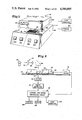
- FIG. 2 is a schematic view of the functional components in the photometer of FIG. 1;
- FIG. 3 is a schematic block diagram of the control and signal processing circuit shown in FIG. 2;
- FIG. 4 is a partially schematic plan view of the X-Y mover shown in FIG. 2;
- FIG. 5 is a fragmentary, perspective view of the X-Y mover shown in FIG. 4;
- FIG. 6 is a partially schematic front elevation of the X-motion carriage and the motorized drive therefor;
- FIG. 7 is a section taken substantially along lines 8--8 of FIG. 6;
- FIG. 8 is a section taken substantially along lines 9--9 of FIG. 6;
- FIG. 9 is a partially schematic front elevation of the Y-motion carriage and the motorized drive therefor;
- FIG. 10 is a section taken substantially along lines 10--10 of FIG. 9;
- FIG. 11 is a section taken substantially along lines 11--11 of FIG. 9;
- FIG. 12 is a plan view of the assembly of the microtitration plate and its holder at a home position relative to the X and Y coordinate axes;
- FIG. 13 is an enlarged fragmentary plan view of one of the wells of the microtest plate shown in FIGS. 1 and 12;
- FIG. 14 is a section taken substantially along lines 14--14 of FIG. 13;
- FIGS. 15A, 16A, 17A, 18A and 19A are fragmentary plan views of the wells similar to FIG. 13 and showing various sizes of hemagglutination buttons;
- FIGS. 15B, 16B, 17B, 18B and 19B are optical density profile graphs of the buttons shown in FIGS. 15A-19A, respectively;
- FIG. 20 is a flow chart of the computer program according to one embodiment of this invention.
- FIG. 21 is a flow chart of the X home subroutine
- FIG. 22 is a flow chart of the Y home subroutine
- FIG. 23 is a flow chart of the run-in subroutine
- FIG. 24 is a flow chart of the read subroutine
- FIG. 25 is a flow chart of the interrupt routine
- FIG. 26 is a flow chart of the X advance subroutine
- FIG. 27 ia a flow chart of the Y advance subroutine
- FIG. 28 is a flow chart of the return subroutine.
- FIG. 29 ia a flow chart for the Tcalc subroutine.
- a photometer 20 incorporating the principles of this invention comprises a suitable casing 22 (FIG. 1) for housing the various components of the instrument, including an optical system 24 (FIG. 2), an electrical control and signal processing circuit 26 (FIG. 2), and an X-Y mover 28 (FIG. 2).
- a suitable casing 22 for housing the various components of the instrument, including an optical system 24 (FIG. 2), an electrical control and signal processing circuit 26 (FIG. 2), and an X-Y mover 28 (FIG. 2).
- Optical system 24 may be of any suitable conventional type. In the illustrated embodiment it is the same as the optical system used in the previously identified MR 600 Microplate Reader.
- optical system 24 comprises a lamp 30 which operates as the optical system's light source, a photodetector 32 for detecting the light transmitted by lamp 30, a light filter 33, a prism 38, and suitable optics including a pair of lenses 34 and 36.
- Lamp 30 may be of any suitable type as a tungsten halogen lamp.
- lamp 30, lenses 34 and 36, and prism 38 are mounted in an upper casing portion 40, and photodetector 32 and filter 33 are mounted in a lower casing portion 42.
- lamp 30 and the optics may be mounted in the lower casing portion 42, and photodetector 32 may be mounted in the upper casing portion 40.
- casing 22 has a support deck or table 44 for slidably supporting a rectangular holder 46.
- a microtitration plate 48 (also referred to as a microtest plate) is adapted to be seated in and supported by holder 46 for unitary displacement therewith.
- Deck 44 forms the top wall of the lower casing portion 42.
- Casing 22 may be the same as the one in the previously identified MR 600 Microplate Reader.
- Plate 48 may be of any suitable conventional clear plastic construction such as the one described in U.S. Pat. No. 3,356,462 which issued to N. M. Cooke et al on Dec. 5, 1967.
- This type of microtitration plate has an 8 ⁇ 12 array of 96 uniformly diametered, upwardly opening sample-holding wells 50. As shown in FIG. 12, wells 50 are uniformly spaced apart to form eight parallel spaced apart 12-well rows in one direction and twelve parallel spaced apart 8-well columns in a direction extending perpendicular to the above-mentioned rows.
- Microtitration plates of this type are customarily provided with alphabetic designations (A through H) for identifying the rows of wells and numerical designations (1 through 12) for identifying the columns of wells in the plate.
- the X-Y mover 28 is connected to holder 46 to move the assembly of holder 46 and plate 48 in a horizontal X-Y coordinate plane to successively bring wells 50 in a preselected order into axial alignment with an aperture 52 through deck 44.
- Light from lamp 32 is focused by lenses 34 and 36 to form a beam which is directed by prism 38 to pass downwardly through the top opening of the selected one of the wells 50 lying in alignment with aperture 52.
- Lenses 34 and 36 focus a beam of the lamp's light on the contents in the aligned well such that the beam passes downwardly through the well's open top, through aperture 52, and through filter 33 to photodetector 32.
- the output signal of photodetector 32 is a measure of the light absorbance and hence the optical density of the contents of well 50 at the point where the light beam passes through the well.
- only one filter of preselected wavelength is used for filtering the light passing through the sample in the well.
- the particulars of the system thus far described are old and are the same as those in the previously identified MR 600 Microplate Reader.
- the X-Y mover 28 is also of conventional construction with exceptions which will be described below.
- Casing 22 has an intermediate portion 53 (see FIG. 1) which houses mover 28.
- mover 28 comprises an X-motion carriage 60 and a Y-motion carriage 62.
- the Y carriage 62 is slidably mounted on a pair of fixed, parallel spaced apart rails 66 for reciprocal horizontal rectilinear movement parallel to the Y axis of the X-Y coordinate plane.
- the X carriage 60 is slidably mounted on a fixed guide rail 68 which is perpendicular to guide rails 66.
- a bar or member 69 is slidably mounted on X carriage 60, extends freely through an opening in casing portion 53, and is fixed at one end to holder 46.
- the other end member 69 slidably receives and is supported by a further guide rail 70, which is fixed on the Y carriage 62.
- Rail 70 is perpendicular to guide rails 66, and member 69 extends perpendicular to rail 70.
- the assembly of X carriage 60 and member 69 is slidably mounted on the Y carriage 62 for reciprocal, rectilinear movement parallel to the X-coordinate axis, which is perpendicular to the Y direction of movement of Y carriage 62.
- member 69 is axially displaceable with the Y carriage 62 parallel to the Y-coordinate axis and is laterally displaceable with the X carriage 60 parallel to the X-coordinate axis.
- the assembly of holder 46 and plate 48 is therefore displaceable in opposite directions parallel to the X-coordinate axis and is also displaceable in opposite directions parallel to the Y-coordinate axis.
- Plate 48 is positioned in such a manner that the alphabetically identified rows of wells 50 are parallel to the X-coordinate axis and the numerically identified columns of wells 50 are parallel to the Y-coordinate axis.
- a motorized drive 72 for driving the X carriage 60 in opposite directions parallel to the X-coordinate axis comprises a motor 74 which is drive connected by a clutch 76 to a toothed pulley 78.
- a drive belt 80 is trained around pulley 78 and another toothed pulley 82.
- Pulley 82 is connected to a brake 84.
- drive belt 80 is fixed to carriage 60 by any suitable means such as a bracket 86.
- drive belt 80 On its inwardly facing side, drive belt 80 is provided with gear-like teeth which mesh with the teeth on pulleys 78 and 82 to prevent slippage of the drive belt.
- a motorized drive 88 for driving the Y carriage 62 in opposite directions parallel to the Y-coordinate axis is the same as the X carriage drive 72. Accordingly, like reference numerals have been used to identify like parts of the two drives, except that the reference numerals used for the Y carriage drive have been suffixed by the letter "a" to distinguish them from the reference numerals used for the X carriage drive.
- drive belt 80a is fixed by the bracket 86a to the Y carriage 62.
- a sensor assembly 100 is employed for sensing the position of plate 48 along the Y-coordinate axis, and a further sensor assembly 101 is employed for sensing the position of plate 48 along the Y-coordinate axis.
- Sensor assembly 100 may be of any suitable conventional type and is preferably the same as the one used in the previously identified MR 600 Microplate Reader.
- sensor assembly 100 comprises a photobeam interrupt comb 102, a position sensor 104, and a home sensor 106.
- Comb 102 is fixed by any suitable means such as a bracket 108 to carriage 60. Comb 102 therefore moves with carriage 60 relative to sensors 104 and 106, which are stationary and which are of the photoelectric type.
- comb 102 has a set of twelve parallel, uniformly spaced apart photobeam-interrupting teeth 110, 111, 112, 113, 114, 115, 116, 117, 118, 119, 120, and 121 which are arranged in a straight row extending parallel to the motion path of carriage 60 and hence to the X-coordinate axis. Tooth 121 at the right hand end of comb 102 (as viewed from FIG. 6) has a width which is greater than the uniform width of the other teeth of the comb.
- Comb 102 and plate 48 are fixed against movement relative to one another along a path extending parallel to the X-coordinate axis.
- the uniform spacing between teeth 110-121 is equal to the uniform spacing between the columns of wells 50 in plate 48.
- sensor 104 comprises a lamp or other suitable light source 123, a photodetector 124 and a U-shaped holder 125 which mounts light source 123 and photodetector 124.
- Photodetector 124 is positioned to detect the light transmitted by light source 123.
- Comb 102 moves with carriage 60 along a path where its teeth 110-121 pass between light source 123 and photodetector 124 at right angles to the light beam to thus interrupt the light beam generated by light source 123.
- sensor 106 also comprises a lamp or other suitable light source 126, a photodetector 127, and a U-shaped holder 128 which mounts light source 126 and photodetector 127.
- the light beam transmitted by light source 126 is detected by photodetector 127.
- Holders 116 and 122 are fixed against movement and may be mounted on any suitable part or member which is indicated at 129 in FIG. 4
- the motion path of comb 102 extends between light source 126 and photodetector 127 such that tooth 121 at the right hand end of comb 102 (as viewed from FIG. 6) interrupts the light beam transmitted by light source 126 upon movement of carriage 60 to its home position.
- sensor assembly 101 also comprises a photobeam interrupt comb 130, a position sensor 104a and a home sensor 106a.
- Sensors 104a and 106a are the same as sensors 104 and 106, respectively. Accordingly, like reference numerals have been applied to designate corresponding components of the two sets of sensors except that the reference numerals used for sensors 104a and 106a have been suffixed by the letter "a" to distinguish them from the reference numerals used for sensors 104 and 106.
- comb 130 is similar to comb 102, but instead of having twelve teeth, it has a set of just eight parallel, uniformly spaced apart photobeam-interrupting teeth 136, 137, 138, 139, 140, 141, 142 and 143 which are arranged in a straight row extending parallel to the motion path of carriage 62 and hence to the Y-coordinate axis.
- the uniform spacing between teeth 136 is equal to the uniform spacing between the rows A-H of wells 50 in plate 48.
- Comb 130 and plate 48 are fixed against relative movement to one another along a path extending parallel to the Y-coordinate axis.
- Comb 130 moves with the X carriage 62 along a path where its teeth 136-143 pass between light source 123a and photodetector 124a at right angles to the light source's beam to thus interrupt the light beam generated by light source 123a.
- the motion path of comb 130 also extends between light source 126a and photodetector 127a such that tooth 143 interrupts the light beam transmitted by light source 126a upon movement of carriage 62 to its home position.
- the light beams generated by light sources 123 and 126 are parallel and are spaced apart by a distance which is greater by a preselected length than the spacing between oppositely facing edges of the comb's endmost teeth 110 and 121.
- the light beams transmitted by light sources 123a and 126a are parallel and are spaced apart by a distance which is greater by a preselected length than the spacing between oppositely facing edges of the comb's endmost teeth 136 and 143. Because of this arrangement, the home position of the assembly of holder 46 and plate 48 will be spaced from the photometer's vertical light beam 146 in the plane where it passes centrally through aperture 52 as shown in FIG. 12.
- plate 48 When the X carriage 60 is advanced away from its home position to a position where tooth 110 interrupts the beam from light source 123, plate 48 will be at a position where a column line 148 (FIG. 12) normally intersecting the longitudinal axes of wells 50 in column 1 perpendicularly intersects the longitudinal photometer's light beam 146.
- plate 48 When carriage 60 is displaced to its next position where tooth 111 interrupts the light beam from light source 123 plate 48 will be at a position where a column line 149 perpendicularly intersecting the longitudinal axes of the wells in column 2 perpendicularly intersects the photometer's light beam 146.
- plate 48 For succeeding X carriage positions at which the beam from light source 123 is interrupted by teeth 112-121, plate 48 will be at locations where corresponding column lines for the plate's columns 3-12 intersect light beam 146.
- the position of comb 130 relative to plate 48 differs from the arrangement in the previously identified MR 600 Microplate Reader and is such that when the Y carriage 62 is displaced away from its home position to a position where tooth 136 interrupts the light beam from light source 123a, the photometer's light beam 146 will be perpendicularly intersected by a row line 150 (FIG. 12) passing through the wells in row A of plate 48 immediately adjacent to the wells' leading edges relative to light beam 146. Line 150 is thus offset from the centers of the wells.
- plate 48 When the Y carriage 62 is advanced to a position where tooth 137 interrupts the beam from light source 123a, plate 48 will be at a position where light beam 146 is intersected by another row line 151 passing through the wells in row B immediately adjacent to the wells' leading edges relative to light beam 46, similar to line 150. For succeeding Y carriage positions where the beam from light source 123a is interrupted by teeth 138-143, plate 48 will be at locations where corresponding row lines for the plate's rows C-H intersect light beam 46.
- the row lines mentioned above are parallel to one another and are perpendicular to the previously mentioned column lines.
- movement of carriages 60 and 62 is programmed in such a way that the carriages are first advanced from their home positions to positions where tooth 110 interrupts the beam from light source 123 and tooth 136 interrupts the light beam from light source 123a, thus locating plate 48 at a position where the photometer's light beam 146 passes through the intersection of lines 148 and 150 and hence through the A1 well in plate 48 immediately adjacent to the well's leading edge where it is substantially offset from the well's centerline.
- the movement of the X carriage is halted while continuing the movement of the Y carriage 62 away from its home position, whereby beam 146 traverses along line 148.
- the photodetector's analog output signal (which is a measure of the intensity of the photometer's light beam and hence the extent to which light has been absorbed) represents a continuous, travelling measurement of the sum of two optical densities, the first being the optical density of the substance in each well diametrically across each entire well, and the second being the optical density of the well's bottom.
- the analog output signal of photodetector 32 is periodically sampled by an analog-to-digital converter 169 as the photometer's light beam diametrically traverses each of the wells 50 in plate 48 to digitize the photodetector's analog output for each of the plate's wells. Any suitable number of signal samples may be taken of the photodetector's analog output for each of the wells 50.
- the twenty-four signal samples of the photodetector's analog output are taken periodically such that the samples are uniformly spaced apart diametrically across each well as shown in FIG. 13. Because the Y carriage 62 is advanced at a uniform speed, the twenty-four samples of the photodetector's analog output signal for each well will be uniformly spaced apart as illustrated in FIG. 13.
- the signal samples are each converted by converter 169 into digital signal form, that is a plural bit word. Sampling of the photodetector's analog output signal is commenced for each of the wells 50 in plate 48 in a manner described below.
- the digital optical density readings for each of the wells 50 are processed by a microcomputer 170 in circuit 26 to produce and to read out a value of the size or diameter of any agglutination button or other solid mass in the bottom of the well.
- the diameter of the hemagglutination button may be indicated by a numerical value on a scale of 1 through 5.5 where the numerical value 1 represents a strong negative reaction, the numerical value 2 represents a weak negative reaction, the numerical value 3 represents an intermediate reaction, the numerical value 4 represents a weak positive reaction, and the numerical value 5 represents a strong positive reaction.
- FIGS. 15A-19A and 15B-19B a strong hemagglutination inhibition reaction results in a small, tight hemagglutination button 200. As the reaction becomes less negative and hence more positive the button size increases, and the button becomes less compact or looser as indicated by the button sizes 201, 202, 203 and 204 in FIGS. 16A-19A, respectively. It will be appreciated that any other suitable numerical values may be used to indicate the button size.
- the digitized optical density measurements for each well may be transmitted to a host computer 210 for plotting a graph showing the optical density pattern or profile of the button or other solid mass in the cross-section, as illustrated, for example, in FIGS. 15B-19B.
- the photometer of this invention is capable of measuring and reading out the size of any particulate or other solid mass in the bottom of a microtest well or other sample-holding vessel.
- the digitized measurements for each sample may also be transmitted to a host computer for plotting the optical density profile of such mass in cross-section. Such plots have particular value for recognizing various patterns of the masses the optical density.
- microcomputer 170 comprises a central processing unit 172 which is connected through an input/output interface 174 to the input and output devices in the system.
- the input devices include sensors 104, 106, 104a, and 106a and converter 169.
- the output devices include motors 74 and 74a, clutches 76 and 76a, brakes 84 and 84a, and one or more suitable read-out devices such as an LED display module 178 and a printer 180.
- Central processing unit 172 inclues a microprocessor 182, or other suitable processor, a read only memory (ROM) 184 for electrically storing the computer's program, and a random access memory (RAM) 186 for storing data and other information.
- the program in ROM 184 provides the instructions for automatically operating the photometer 20 and for generating the readings read out on display 178 and/or printer 180.
- the flow chart for the resident program is shown in FIGS. 20-29.
- the program commences with a start or power-up step 200 in which power is applied to the photometer by operating an on/off power switch 222 on a front panel of casing 22.
- the power-up step 220 is followed by an initialization step 223 which may be the same as the one used in the previously identified MR 600 Microplate Reader for initializing various pointers and counters in the CPU, for clearing internal processor registers and conducting other housekeeping operations such as disabling all interrupts, turning off motors 74 and 74a, disengaging clutches 76 and 76a and releasing brakes 84 and 84a.
- step 224 is entered to check or interrogate sensors 106 and 106a. If carriage 60 is in its home position, sensor 106 will transmit an interrupt signal to microprocessor 182. If carriage 62 is in its home position, sensor 106a will transmit a similar interrput signal to microprocessor 182. Sensor 106 generates its interrupt signal when tooth 121 interrupts the light beam from source 126, and sensor 106a generates its interrupt signal beam when tooth 143 interrupts the light beam from source 126a.
- a decision step 226 is entered to look at the signal from sensor 106 to determine whether the X carriage 60 is in its home position. If the decision is affirmative, a second sensor input step 228 is entered. If the decision at step 226 is negative, step 229 is entered to call an X home subroutine 230 (FIG. 21) to commence movement of carriage 60 towards its home position.
- the X home subroutine commences with a start reverse step 232 for carriage 60.
- brake 84 is released, clutch 76 is engaged and motor 74 is actuated in the reverse direction.
- step 234 Upon commencing motion of the X carriage 60, step 234 is entered to set or turn on an X-motion flag in RAM 186.
- the X-motion flag is simply a coded plural bit word which is placed in RAM 186 to inform microprocessor 182 that carriage 60 is in motion.
- an enable position interrupt step 236 is entered.
- microprocessor 182 is conditioned to recognize an interrupt signal from sensor 106 and, upon reception of the interrupt signal, to execute a position interrupt service or routine 237 (FIG. 25), which will be explained in detail later on.
- each of the sensors 104, 106, 104a and 106a generates its interrupt signal when its light beam is interrupted.
- Step 228 is the same as step 224 for checking or interrogating the signal status of sensors 106 and 106a.
- a further decision step 240 is entered. Based on the signals supplied at step 228, step 240 determines whether or not the Y carriage 62 is at its home position. If the decision for step 240 is affirmative (signifying that carriage 62 is at its home position) a motion flag recall step 242 is entered. If carriage 62 is not at its home position, step 243 is entered to call a Y home subroutine 224 for commencing reverse motion of carriage 62.
- the steps in subroutine 244 correspond to those in the X home subroutine 220. Accordingly like reference numerals have been applied to designate similar or corresponding steps in the two subroutines except that the reference numerals used to designate the steps in subroutine 244 have been suffixed by the letter "a" to distinguish them from the reference numerals used for the steps in subroutine 220.
- the steps in subroutine 244 are applicable to the Y carriage 62 and its home sensor 106a.
- clutch 76a is engaged, brake 84a is released and motor 74a is actuated in the reverse direction to commence motion of carriage 62 towards its home position.
- a Y-motion flag (a plural bit word in RAM 186) is set or turned on to inform microprocessor 182 that carriage 62 is in motion.
- microprocessor 182 is conditioned to recognize an interrupt signal from sensor 106a and to execute the interrupt routine 237.
- microprocessor 182 When the X carriage 60 arrives at its home position, it causes sensor 106 to transmit an interrupt signal to microprocessor 182. Alternatively, carriage 62 may arrive at its home position first, causing sensor 106a to transmit its interrupt signal. In either case, microprocessor 182 will now proceed to execute the interrupt routine 237.
- the interrupt service or routine 237 commences with a decision step 300 to determine if the X-motion flag is set. If the decision at step 300 is affirmative another decision step at 304 is entered to determine if the X carriage motion is forward or reverse. At this point of the operation, the motion will be in the reverse to proceed to an input step 306 where the signal from home sensor 106 is interrogated.
- step 308 is entered to determine if carriage 60 has arrived at its home position by examining the signal from input step 306. If the decision at step 308 is negative, the operation proceeds to decision step 302. If, on the other hand, the decision at step 308 is affirmative, a reset step 310 is entered to reset an X position counter 312 (see FIG. 3) to zero and to reset or turn off the X-motion flag. An output step 314 is then entered to disengage clutch 76, turn off motor 74 and apply brake 84, thus halting motion of the X carriage 60 at its home position.
- decision step 302 is entered to determine if the Y-motion flag is set or on. If it is not, the operation proceeds to a further decision step 316. If it is, the operation proceeds to yet another decision step 318 to determine whether the motion of the Y carriage 62 is forward or reverse. In this instance, the motion of carriage 62 will be in the reverse, thus entering an input step 320 where the signal from sensor 106a is interrogated. This signal is operated on at a following decision step 322. If the signal from sensor 106a indicates that carriage 62 is in its home position, a reset step 326 is entered to reset the Y-motion position counter 328 (FIG. 3) to zero and to reset or turn off the Y-motion flag. Each of the position counters 312 and 328 is a block of memory locations in RAM 186 which are incremented during motion of their respective carriages to indicate the X, Y coordinate positions of plate 48. The technique for providing such counters is conventional.
- step 330 is entered to turn off motor 74a, to disengage clutch 76a and to apply brake 84a, thus stopping the Y carriage 62 at its home position.
- both carriages 60 and 62 will be at their home positions.
- decision step 316 is entered to determine if the X-motion flag and/or Y-motion flags are still on. If the decision at step 316 is negative, an interrput disable step 330 is entered to disable the interrupt status in microprocessor 182, thus completing the execution of the position interrupt service 237 and returning at 332 in the main program. If either or both of the X-motion and Y-motion flags are still on, the decision at step 316 will be affirmative to enter another enable interrupt step 336 which again conditions microprocessor 182 to recognize the interrupt signals from sensors 106 and 106a and to thus place the processor in a condition for re-executing the interrupt routine 237.
- Step 242 recalls the X-motion and Y-motion flag conditions in memory 186. Based on the conditions of the flags, decision step 246 determines whether the motion of carriages 60 and 62 have been completed. If either or both of the flags are in their set conditions(to indicate that either or both of the carriages 60 and 62 are still in motion), the decision at step 246 will be negative to enter a waiting loop 247, thus looping the operation back to step 242.
- the waiting loop will continue until the X-motion and Y-motion flags are reset, at which time the decision at step 246 becomes affirmative, causing the operation to advance to an input step 248 to interrogate the condition or status of an on/off run switch 252 (see FIG. 1).
- Switch 252 is located on the front panel of photometer 20.
- run switch 252 If run switch 252 is not on, the decision at decision step 250 is negative to enter a waiting loop 254. When run switch 252 is manually turned on by the operator an affirmative decision occurs at decision step 250, the waiting loop 254 is exited, and step 255 is entered to call a run-in subroutine 256 (FIG. 23).
- subroutine 256 commences with a step 258 which commands the microprocessor 182 to turn on a run light 260 (see FIG. 1) on the front panel of the photometer.
- a step 261 is entered to call a read subroutine 260 (FIG. 24).
- the read subroutine instructs microprocessor 182 to operate the analog-to-digital converter 169 in such a manner that the converter periodically samples the analog output of photodetector 32, thus producing a preselected number of digitized optical density readings of the photodetector's analog output.
- converter 169 operates to take twenty-four readings of the photodetector's output for each execution of subroutine 262. The twenty-four readings are taken at a constant frequency, whereby the time durations between the readings are equal.
- carriages 60 and 62 When the read subroutine 262 is first executed, carriages 60 and 62 will be at their home positions, thus locating plate 48 at a position where it is spaced from the path of the photometer's light beam 146. Beam 146 therefore passes only through the air, and the twenty-four reading of the photodetector's analog output therefore represent the optical density of the ambient condition in which the photometer is operating. These twenty-four readings are averaged to produce what is customarily referred to as an "air blank" reference which is stored in RAM 186. At a later stage in the operation, the air blank reference is subtracted from the optical density reading obtained for each well 50 to correct for the effect of ambient air on the optical density readings.
- the read subroutine 262 commences with a step 270 which initializes a reading number counter 272 (see FIG. 3) and a pointer (not shown) for counter 272.
- Counter 272 is a block of RAM memory locations in which a pointer is incremented by microprocessor 182 to keep a count of the number of readings or samples taken by converter 169 for each sampling operation. Such a counting technique is conventional.
- Counter 272 also provides the addresses at which the digital output signals of converter 169 are stored in RAM 186.
- a set time step 274 is entered.
- a CPU timer (not shown) is conditioned to set the "wake-up" time for microprocessor 182 preparatory to a following step 276 in which microprocessor 182 is placed in its halt or sleep state.
- microprocessor 182 is placed in its halt step and when the CPU timer times out, the microprocessor is placed in its active or wake-up state to enter a signal sampling and conversion step 278 in which converter 169 is operated to sample the analog output of photodetector 32 and to convert the sample into a plural digital word for storage in RAM 186.
- the constant signal sampling frequency is such that the time required for taking the twenty-four digital readings is just slightly shorter than the time taken by carriage 62 to travel the diameter of the microtest well 50, thus ensuring that twenty-four digital optical density readings will be taken at each well 50.
- a decision step 280 is entered to determine if converter 169 has completed the conversion of the analog sample presently being taken. If the decision is negative, a waiting loop 282 is entered until the digital conversion is completed, at which time the decision becomes affirmative to advance to a data storage step 284.
- the digitized optical density reading is stored in a reader buffer portion 286 (FIG. 3) of RAM 186 at an address location indicated by a reader buffer pointer (not shown). The pointer for reading buffer 286 is thereupon incremented or advanced to the next address location in the reader buffer.
- a counter incrementing step 288 is entered in which counter 272 is incremented so that it will have a count of the number of digitized optical density measurements thus far stored in buffer 286 for a given execution of subroutine 262.
- a decision step 290 is entered to determine if all twenty-four digital optical density readings have been taken for a given execution of subroutine 262. If the decision for step 290 is negative, the operation proceeds to a timer-setting step 292 which is the same as step 274. From step 292 a loop 294 is entered to repeat the portion of subroutine 262 commencing with step 276. Each time this portion of subroutine 262 is executed, another sample of the output of photodetector 32 is taken and converted by converter 169 into a digital signal or word which is stored in buffer 286.
- step 290 When all twenty-four readings are taken and stored to complete the sampling operation, the decision at step 290 becomes affirmative, thus completing the execution of subroutine 262 and returning at 296 to the run-in subroutine 256 (FIG. 23) Upon returning to subroutine 256, a step 297 is entered to call an X advance subroutine 298 (FIG. 26). Except for the direction in which the X-motion motor 74 is advanced, the X advance subroutine 298 is the same as the X home subroutine 220.
- the X advance step 232a differs from the X home subroutine 220 in that motor, instead of being advanced in the reverse direction, is now advanced in the forward direction to displace carriage 60 away from its home position for moving plate 48 towards the path of the photometer's light beam 146.
- a Y advance subroutine 350 (FIG. 27) is called. Except for the direction in which the Y-motion motor 74a is advanced, the Y advance subroutine 350 is the same as the Y home subroutine 244. Accordingly, like reference characters have been used to designate like steps in the two subroutines except that the letter "c" has been substituted in the reference characters for subroutine 350 to distinghish them from the reference characters used for subroutine 244.
- the Y advance step 232c differ from the Y home subroutine 244 in that motor, instead of being advanced in the reversed direction, is now advanced in the forward direction to displace carriage 62 away from its home position for moving plate 48 towards the path of the photometer's light beam 146.
- both carriages 60 and 62 are travelling forward in directions to advance the A1 well in plate 48 towards the photometer's light beam path 146.
- execution of the Y advance subroutine 350 operation is returned to the run-in routine 256 at step 351 to call a return subroutine 352 (FIG. 28).
- the return subroutine 352 comprises a decision step 354 for checking the condition of a return switch 356 (see FIG. 1) on the front panel of the photometer. If return switch 356 is on, the operating sequence is reinstated to return carriages 60 and 62 to their home positions, thus aborting the reading operation. If the return switch is off, operation is returned to the run-in subroutine where a further decision step 358 is entered. Decision step 358 checks the X- and Y-motion flags to determine if there is motion of either one or both of the carriages 60 and 62. If either or both of the carriages 60 and 62 are still in motion a waiting loop 360 is entered.
- microprocessor 182 Upon receiving the first interrupt signal (say the signal from sensor 104) microprocessor 182 calls and executes the interrupt routine 237. At this point the X-motion flag is set so that the decision at step 300 will be affirmative, thus entering step 304. At step 304 the decision is made that the motion of carriage 60 is forward, thus entering the input step 364 to check the signal status of sensor 104.
- step 366 is entered which looks at the input from sensor 104 to determine if carriage 60 has arrived at the position where tooth 110 interrupts the light beam from source 123. If the decision is negative step 302 is entered to check the Y-motion flag. If the decision at step 366 is affirmative, step 368 is entered to increment the X postition counter 312 and to reset or turn off the X-motion flag. Following step 368, an output step 370 is entered to disengage clutch 76 and apply brake 84 to stop the motion of carriage 60 at the position where the photometer's light beam 146 intersects the column line 148 (FIG. 12).
- decision step 302 is entered to check the Y-motion flag, and if it is on, decision step 318 is entered. At this stage of the operation the motion of carriage 62 will be forward, thus entering another input step 372 to check the signal from sensor 104a.
- step 374 If carriage 62 has arrived at the position where sensor 104a is transmitting its interrupt signal, the ensuing decision step 374 responds affirmatively with the result that step 376 is entered. If carriage 62 has not as yet reached the position where tooth 136 interrupts the light beam from source 126a the decision at step 374 will be negative, thus directing the operation to enter step 316. Assuming that the decision at step 374 is affirmative, step 376 is entered to increment the Y position counter and to reset the Y-motion flag. Following step 376, step 316 is entered to execute the remainder of the interrupt routine.
- step 358 Upon the return from routine 237 to the run-in routine (FIG. 23), the decision at step 358 now becomes negative because both the X- and Y-motion flags have been reset, although the Y carriage 62 is still travelling in the forward direction.
- step 390 is entered to recall the read subroutine 262 while carriage 62 is still travelling in its forward direction where the movement of plate 48 is such that the photometer's light beam 146 traverses along line 148 diametrically across the A1 well in plate 48. Therefore, in this execution of the read subroutine 262 converter 169 will sample the analog output of photodetector 32 at points 360-1 through 360-24 as shown in FIG. 13.
- the A1 well in plate 48 has been preselected as the blanking well. Therefore no reagents, blood or other material are placed in the A1 well so that the twenty-four digital optical density measurements across the diameter of the well will be electrically processed to provide a blanking reference which indicates the optical density of the well's bottom. This blanking reference and the previously described air blank are substracted from the optical density readings made for the other wells in plate 48 to obtain accurate optical density readings of the materials in the other wells of plate 48.
- step 400 in the run-in routine to determine whether all eight wells in the plate's column of wells have been read.
- the count in counter 328 will indicate the number of wells thus far read in the columns. Since only the first well in column 1 has been read at this stage the decision is negative, thus entering step 402 to call the Y advance subroutine 350.
- Execution of the Y advance subroutine 350 at this stage sets the Y-motion flag and enables the microprocessor interrupt to recondition microprocessor 182 to recognize an interrupt signal from the sensor 104a and to execute the interrupt routine 237 upon reception of such interrupt.
- the execution of the Y advance subroutine at this stage is not required to recommence forward motion of carriage 62 because it already is in motion along line 148.
- step 404 is entered to call and execute the return subroutine 352. Assuming that the return switch 356 is still off a decision step 406 is entered to check the X-motion and Y-motion flags for their set conditions. If either or both of the motion flags are set, a waiting loop 408 is entered until both flags are reset.
- the decision at step 406 will be negative, thus entering a further decision step 409 to determine if carriage 62 is at its home position. At this stage, carriage 62 will be away from its home position.
- the decision at step 409 is therefore negative causing the operation to enter a loop 410 to re-execute the portion of the run-in subroutine 256 commencing with step 390, which again calls the read subroutine 262 for producing and storing twenty-four optical density digital readings of the contents in the B1 well at equally spaced apart points diametrically across the well along column line 148 in the same manner described for the A1 well.
- the operation remains in loop 410 repeating itself for each of the remaining wells in column 1 of plate 48.
- microprocessor 182 executes the previously described interrupt service routine 237. As a result, the Y-motion flag will be reset or turned off.
- a further step 422 is entered to call a Tcalc subroutine 424 (FIG. 29).
- the Tcalc subroutine 424 computes a suitable numerical value such as the previously described value ranging from 1 to 5.5 to indicate the size of the agglutination button or other solid mass in the bottom of the well and also to indicate the extent or nature of the reaction as in the case, for example, of the previously described hemagglutination inhibition reaction or assay.
- subroutine 424 commences with a step 426 where the first four and the last five of the twenty-four stored optical density measurements are deleted. Following step 426 a further step 428 is entered to determine which of the remaining optical density measurements has the highest optical density value. Thereafter, a step 430 is entered to establish a threshold as a preselected percentage of the highest optical density value, which highest value was determined in step 428. Such percentage may, for example, be 70% of the highest optical density value. Thereafter, step 432 is entered to identify and count the number of optical density measurements having values greater than the above mentioned threshold.
- step 434 is entered in which the number of optical density measurements above the threshold is divided by two, and the quotient is reduced by a preselected number such as two to produce an answer equal to the quotient minus two.
- the answer is formatted and may be placed in a print buffer (not shown) for readout and/or a transmit buffer (not shown) for tranmission to computer 210 for further processing.
- a decision step 438 is entered to determine if answers for all eight wells in the column just scanned have been computed. If not, the operation enters a loop 440 to repeat execution of the subroutine 424 until the answers for all eight wells are obtained and stored in RAM 186, at which time the decision at step 438 becomes affirmative to return operation to the run-in routine 256.
- the operation next enters a step 442 for calling a print subroutine (not shown) and/or a data transmit subroutine (also not shown).
- a print subroutine not shown
- a data transmit subroutine also not shown.
- Each of these subroutines may be of any suitable type.
- the print subroutine operates printer 180 to provide a print-out for each well 50 in the scanned column of wells.
- the print-out for each well includes the well's designation (e.g., A1, B1, etc.) and its associated answer (the computed reading) obtained by execution of subroutine 424.
- the transmit subroutine provides for the transmission of the computed answers and/or the raw data (the individual sets of twenty-four optical density measurments for each well) to computer 210 or other equipment for further processing.
- another subroutine may be used to read out the answers and their associated well designations on display 178, which may be of the LED type. Display 178 may also be operated to read out the X-Y coordinate position of plate 48 relative to beam 146 in terms of the microtest plate well designations (e.g., A1, B1, etc.) while the scanning and optical density reading operation is in progress.
- a decision step 444 is entered to check or interrogate the Y-motion flag to determine if carriage 62 is still in the process of returning to its home position. If movement of carriage is still in progress a waiting loop 446 is entered.
- next decision step 448 which determines whether or not the present position of carriage 60 is the last position in the X direction, that is, the plate position where the column line 450 (see FIG. 12) perpendicularly intersecting the longitudinal axes of the wells in column 12 intersects the photometer's light beam 146. In essence, this decision step determines whether all of the wells 50 in plate 48 have been read.
- Step 448 therefore interrogates the X position counter and if the count is not 12, the decision is negative to enter a further step 452 for calling the X advance subroutine 298.
- Execution of the X advance subroutine imparts motion to carriage 60 in the forward direction to move over to column 2 in plate 48 while the Y carriage 62 is still at its home position.
- step 404 is re-entered and if the return switch is still off, the X- and Y-motion flags are checked at step 406 as previously described. Assuming that both flags have been reset, decision step 409 is re-entered. At this stage, carriage 62 is at its home position resulting in an affirmative decision to proceed to step 455 for again calling the Y advance subroutine 350 and thus commencing the forward motion of carriage 62 for scanning and reading the wells in column 2 similar to the operation previously described for column 1.
- step 448 the decision at step 448 now becomes affirmative to proceed to step 457 where the X home subroutine 220 is called for returning carriage 60 to its home position. Because of the interrupt produced by returning carriages 60 and 62 to their home positions, the X- and Y-motion flags will at this time be reset. As a result, a negative decision will be made at step 458 to proceed to step 460 for turning off the run light and returning the operation to the main program at step 248 (FIG. 20) in preparation for another run.
- the digital readings or conversions made by converter 169 will be at ponts which are uniformly spaced apart from one another by 0.01 inch diametrically across the well (that is, along a line extending diametrically of the well and therefore prependicularly intersecting the well's longitudinal axis.
Abstract
Description
Claims (13)
Priority Applications (1)
| Application Number | Priority Date | Filing Date | Title |
|---|---|---|---|
| US06/546,451 US4580895A (en) | 1983-10-28 | 1983-10-28 | Sample-scanning photometer |
Applications Claiming Priority (1)
| Application Number | Priority Date | Filing Date | Title |
|---|---|---|---|
| US06/546,451 US4580895A (en) | 1983-10-28 | 1983-10-28 | Sample-scanning photometer |
Publications (1)
| Publication Number | Publication Date |
|---|---|
| US4580895A true US4580895A (en) | 1986-04-08 |
Family
ID=24180479
Family Applications (1)
| Application Number | Title | Priority Date | Filing Date |
|---|---|---|---|
| US06/546,451 Expired - Lifetime US4580895A (en) | 1983-10-28 | 1983-10-28 | Sample-scanning photometer |
Country Status (1)
| Country | Link |
|---|---|
| US (1) | US4580895A (en) |
Cited By (120)
| Publication number | Priority date | Publication date | Assignee | Title |
|---|---|---|---|---|
| US4730921A (en) * | 1985-10-31 | 1988-03-15 | Genetic Systems, Inc. | Photodensitometer for minimizing the refractive effects of a fluid sample |
| US4737464A (en) * | 1985-09-26 | 1988-04-12 | Molecular Devices Corporation | Solid-state optical assay imaging apparatus |
| US4817785A (en) * | 1985-03-01 | 1989-04-04 | Sherwood Medical Company | Automated microbiological testing apparatus |
| US4856073A (en) * | 1985-02-27 | 1989-08-08 | Sherwood Medical Company | Automated microbiological testing apparatus and method |
| US4873633A (en) * | 1985-10-18 | 1989-10-10 | Cetus Corporation | User controlled off-center light absorbance reading adjuster in a liquid handling and reaction system |
| US5041387A (en) * | 1981-04-06 | 1991-08-20 | Rolf Zander | Determination of the acid-base status of blood |
| FR2669428A1 (en) * | 1990-11-16 | 1992-05-22 | Alcyon Analyzer Sa | AUTOMATIC COLORIMETRY SAMPLE ANALYZER. |
| US5192692A (en) * | 1989-07-25 | 1993-03-09 | Olympus Optical Co., Ltd. | Method of judging particle agglutination pattern |
| US5234665A (en) * | 1990-05-25 | 1993-08-10 | Suzuki Motor Corporation | Apparatus for measuring aggregation patterns on a microplate |
| US5265169A (en) * | 1990-10-31 | 1993-11-23 | Suzuki Motor Corporation | Method of discriminating particle aggregation pattern |
| US5311426A (en) * | 1988-08-02 | 1994-05-10 | Abbott Laboratories | Apparatus and method for providing assay calibration data |
| US5325295A (en) * | 1989-05-04 | 1994-06-28 | The United States Of America As Represented By The Secretary Of The Department Of Health And Human Services | Adaptation of microtiter plate technology to measurement of platelet aggregation |
| US5340747A (en) * | 1992-03-09 | 1994-08-23 | Difco Laboratories, Inc. | Diagnostic microbiological testing apparatus and method |
| US5391352A (en) * | 1993-09-07 | 1995-02-21 | Hendrix; Billy E. | Blood analysis apparatus |
| WO1995012808A1 (en) * | 1993-11-01 | 1995-05-11 | Nanogen, Inc. | Self-addressable self-assembling microelectronic systems and devices for molecular biological analysis and diagnostics |
| US5487112A (en) * | 1990-02-20 | 1996-01-23 | Board Of Regents, The University Of Texas System | Method and apparatus for time-resolved measurements of lymphocyte function and aggregate structure using computer-automated microscopy |
| US5594808A (en) * | 1993-06-11 | 1997-01-14 | Ortho Diagnostic Systems Inc. | Method and system for classifying agglutination reactions |
| US5632957A (en) * | 1993-11-01 | 1997-05-27 | Nanogen | Molecular biological diagnostic systems including electrodes |
| US5653939A (en) * | 1991-11-19 | 1997-08-05 | Massachusetts Institute Of Technology | Optical and electrical methods and apparatus for molecule detection |
| US5657118A (en) * | 1996-01-23 | 1997-08-12 | Lee; John T. S. | Device and method for detection/measurement of light |
| US5681530A (en) * | 1993-06-11 | 1997-10-28 | Ortho Diagnostic Systems Inc. | Transport system for fluid analysis instrument |
| US5798085A (en) * | 1996-02-21 | 1998-08-25 | Biomerieux Vitek, Inc. | Optical reader and sample card transport stations for biological sample testing machine |
| US5817475A (en) * | 1996-11-15 | 1998-10-06 | Giles Scientific, Inc. | Automatic microbiological testing apparatus and method |
| US5834758A (en) * | 1994-09-02 | 1998-11-10 | Affymetrix, Inc. | Method and apparatus for imaging a sample on a device |
| US5849486A (en) * | 1993-11-01 | 1998-12-15 | Nanogen, Inc. | Methods for hybridization analysis utilizing electrically controlled hybridization |
| US5853666A (en) * | 1997-02-12 | 1998-12-29 | Biomerieux Vitek, Inc. | Optical reader and sample card transport stations for biological sample testing machine |
| EP0950892A2 (en) * | 1998-04-17 | 1999-10-20 | Labsystems Oy | Device for measuring optical density |
| US5981956A (en) * | 1996-05-16 | 1999-11-09 | Affymetrix, Inc. | Systems and methods for detection of labeled materials |
| US5985214A (en) * | 1997-05-16 | 1999-11-16 | Aurora Biosciences Corporation | Systems and methods for rapidly identifying useful chemicals in liquid samples |
| US6017696A (en) * | 1993-11-01 | 2000-01-25 | Nanogen, Inc. | Methods for electronic stringency control for molecular biological analysis and diagnostics |
| US6036920A (en) * | 1996-05-09 | 2000-03-14 | 3-Dimensional Pharmaceuticals, Inc. | Microplate thermal shift assay apparatus for ligand development and multi-variable protein chemistry optimization |
| US6048690A (en) * | 1991-11-07 | 2000-04-11 | Nanogen, Inc. | Methods for electronic fluorescent perturbation for analysis and electronic perturbation catalysis for synthesis |
| US6051380A (en) * | 1993-11-01 | 2000-04-18 | Nanogen, Inc. | Methods and procedures for molecular biological analysis and diagnostics |
| US6068818A (en) * | 1993-11-01 | 2000-05-30 | Nanogen, Inc. | Multicomponent devices for molecular biological analysis and diagnostics |
| AU728330B2 (en) * | 1996-02-21 | 2001-01-04 | Biomerieux Vitek, Inc. | Automatic sample testing |
| US6225059B1 (en) | 1993-11-01 | 2001-05-01 | Nanogen, Inc. | Advanced active electronic devices including collection electrodes for molecular biological analysis and diagnostics |
| US6254827B1 (en) | 1993-11-01 | 2001-07-03 | Nanogen, Inc. | Methods for fabricating multi-component devices for molecular biological analysis and diagnostics |
| US6261776B1 (en) | 1989-06-07 | 2001-07-17 | Affymetrix, Inc. | Nucleic acid arrays |
| US6287517B1 (en) | 1993-11-01 | 2001-09-11 | Nanogen, Inc. | Laminated assembly for active bioelectronic devices |
| US6310189B1 (en) | 1989-06-07 | 2001-10-30 | Affymetrix, Inc. | Nucleotides and analogs having photoremoveable protecting groups |
| US6309822B1 (en) | 1989-06-07 | 2001-10-30 | Affymetrix, Inc. | Method for comparing copy number of nucleic acid sequences |
| US6309602B1 (en) | 1993-11-01 | 2001-10-30 | Nanogen, Inc. | Stacked, reconfigurable system for electrophoretic transport of charged materials |
| US6315953B1 (en) | 1993-11-01 | 2001-11-13 | Nanogen, Inc. | Devices for molecular biological analysis and diagnostics including waveguides |
| US6319472B1 (en) | 1993-11-01 | 2001-11-20 | Nanogen, Inc. | System including functionally separated regions in electrophoretic system |
| US6331274B1 (en) | 1993-11-01 | 2001-12-18 | Nanogen, Inc. | Advanced active circuits and devices for molecular biological analysis and diagnostics |
| US6355432B1 (en) | 1989-06-07 | 2002-03-12 | Affymetrix Lnc. | Products for detecting nucleic acids |
| US6375899B1 (en) | 1993-11-01 | 2002-04-23 | Nanogen, Inc. | Electrophoretic buss for transport of charged materials in a multi-chamber system |
| US6379895B1 (en) | 1989-06-07 | 2002-04-30 | Affymetrix, Inc. | Photolithographic and other means for manufacturing arrays |
| US6403367B1 (en) | 1994-07-07 | 2002-06-11 | Nanogen, Inc. | Integrated portable biological detection system |
| US6406844B1 (en) | 1989-06-07 | 2002-06-18 | Affymetrix, Inc. | Very large scale immobilized polymer synthesis |
| US6420169B1 (en) | 1989-06-07 | 2002-07-16 | Affymetrix, Inc. | Apparatus for forming polynucleotides or polypeptides |
| US20020119484A1 (en) * | 1994-07-07 | 2002-08-29 | Nanogen, Inc. | Primer extension detection methods on active electronic microarrays |
| US6451536B1 (en) | 1990-12-06 | 2002-09-17 | Affymetrix Inc. | Products for detecting nucleic acids |
| US6468740B1 (en) | 1992-11-05 | 2002-10-22 | Affymetrix, Inc. | Cyclic and substituted immobilized molecular synthesis |
| US6506558B1 (en) | 1990-03-07 | 2003-01-14 | Affymetrix Inc. | Very large scale immobilized polymer synthesis |
| US20030017081A1 (en) * | 1994-02-10 | 2003-01-23 | Affymetrix, Inc. | Method and apparatus for imaging a sample on a device |
| US20030039997A1 (en) * | 1997-09-22 | 2003-02-27 | Aventis Research And Technologies Gmbh & Co. Kg | Pentopyranosyl nucleic acid arrays, and uses thereof |
| US20030059929A1 (en) * | 1993-11-01 | 2003-03-27 | Nanogen, Inc. | Methods for electronic synthesis of complex structures |
| US6545264B1 (en) | 1998-10-30 | 2003-04-08 | Affymetrix, Inc. | Systems and methods for high performance scanning |
| US20030073122A1 (en) * | 1993-11-01 | 2003-04-17 | Nanogen, Inc. | Methods for determination of single nucleic acid polymorphisms using a bioelectronic microchip |
| US6551784B2 (en) | 1989-06-07 | 2003-04-22 | Affymetrix Inc | Method of comparing nucleic acid sequences |
| US6566495B1 (en) | 1989-06-07 | 2003-05-20 | Affymetrix, Inc. | Very large scale immobilized polymer synthesis |
| US6569631B1 (en) | 1998-11-12 | 2003-05-27 | 3-Dimensional Pharmaceuticals, Inc. | Microplate thermal shift assay for ligand development using 5-(4″dimethylaminophenyl)-2-(4′-phenyl)oxazole derivative fluorescent dyes |
| US6569382B1 (en) | 1991-11-07 | 2003-05-27 | Nanogen, Inc. | Methods apparatus for the electronic, homogeneous assembly and fabrication of devices |
| US20030108899A1 (en) * | 1989-06-07 | 2003-06-12 | Affymetrix, Inc. | Very large scale immobilized polymer synthesis |
| US20030128371A1 (en) * | 2000-01-24 | 2003-07-10 | Vaux David John | Method and apparatus for measuring surface configuration |
| US6638482B1 (en) | 1993-11-01 | 2003-10-28 | Nanogen, Inc. | Reconfigurable detection and analysis apparatus and method |
| US6652808B1 (en) | 1991-11-07 | 2003-11-25 | Nanotronics, Inc. | Methods for the electronic assembly and fabrication of devices |
| US6706473B1 (en) | 1996-12-06 | 2004-03-16 | Nanogen, Inc. | Systems and devices for photoelectrophoretic transport and hybridization of oligonucleotides |
| US20040077074A1 (en) * | 1993-11-01 | 2004-04-22 | Nanogen, Inc. | Multi-chambered analysis device |
| US6726880B1 (en) | 1993-11-01 | 2004-04-27 | Nanogen, Inc. | Electronic device for performing active biological operations and method of using same |
| US20040086917A1 (en) * | 1995-09-27 | 2004-05-06 | Nanogen, Inc. | Methods for electronic fluorescent perturbation for analysis and electronic perturbation catalysis for synthesis |
| US20040087010A1 (en) * | 2002-11-04 | 2004-05-06 | Chung-Hua Tsai | Micro ELISA reader |
| US20040096883A1 (en) * | 1994-02-10 | 2004-05-20 | Affymetrix, Inc., A California Corporation | Scanned image alignment systems and methods |
| US6741344B1 (en) | 1994-02-10 | 2004-05-25 | Affymetrix, Inc. | Method and apparatus for detection of fluorescently labeled materials |
| US20040146880A1 (en) * | 2002-07-26 | 2004-07-29 | Nanogen, Inc. | Methods and apparatus for screening and detecting multiple genetic mutations |
| US20050110989A1 (en) * | 2003-11-21 | 2005-05-26 | Schermer Mack J. | Optical device integrated with well |
| US20050118706A1 (en) * | 1989-06-07 | 2005-06-02 | Affymetrix, Inc. | Polymer arrays |
| US20050259258A1 (en) * | 2004-05-19 | 2005-11-24 | Nippon Sheet Glass Company, Limited | Light detection device |
| US20060065531A1 (en) * | 2004-09-23 | 2006-03-30 | Nanogen, Inc | Methods and materials for optimization of electronic transportation and hybridization reactions |
| US20060187442A1 (en) * | 2003-07-19 | 2006-08-24 | Digital Bio Technology | Device for counting micro particles |
| US7101661B1 (en) | 1993-11-01 | 2006-09-05 | Nanogen, Inc. | Apparatus for active programmable matrix devices |
| US7122321B2 (en) | 1997-11-12 | 2006-10-17 | Johnson & Johnson Pharmaceutical Research & Development, L.L.C. | High throughput method for functionally classifying proteins identified using a genomics approach |
| US20070009395A1 (en) * | 2005-07-06 | 2007-01-11 | Genetix Limited | Methods and apparatus for imaging and processing of samples in biological sample containers |
| US20070019199A1 (en) * | 2005-07-25 | 2007-01-25 | The Wisconsin Alumni Research Foundation | Methods, systems, and computer program products for optimization of probes for spectroscopic measurement in turbid media |
| US20070138024A1 (en) * | 2004-09-21 | 2007-06-21 | Swanson Paul D | Electrode based patterning of thin film self-assembled nanoparticles |
| US20070197911A1 (en) * | 2006-01-27 | 2007-08-23 | Affymetrix, Inc. | System, Method, and Product for Imaging Probe Arrays with Small Feature Sizes |
| US7314708B1 (en) | 1998-08-04 | 2008-01-01 | Nanogen, Inc. | Method and apparatus for electronic synthesis of molecular structures |
| US20080047832A1 (en) * | 1994-07-07 | 2008-02-28 | Nanogen | Integrated portable biological detection system |
| US20080227653A1 (en) * | 1989-06-07 | 2008-09-18 | Fodor Stephen P A | Expression monitoring by hybridization to high density oligonucleotide arrays |
| US20080270091A1 (en) * | 2007-02-23 | 2008-10-30 | Nirmala Ramanujam | Scaling method for fast monte carlo simulation of diffuse reflectance spectra from multi-layered turbid media and methods and systems for using same to determine optical properties of multi-layered turbid medium from measured diffuse reflectance |
| US20090010524A1 (en) * | 1994-02-10 | 2009-01-08 | Affymetrix, Inc. | Methods and apparatus for detection of fluorescently labeled materials |
| US20090015826A1 (en) * | 2006-03-30 | 2009-01-15 | Duke University | Optical assay system for intraoperative assessment of tumor margins |
| CN100520374C (en) * | 2003-07-19 | 2009-07-29 | 数字生物技术公司 | Device for counting micro particles |
| US20100189338A1 (en) * | 2008-04-09 | 2010-07-29 | Nexcelom Bioscience | Systems and methods for counting cells and biomolecules |
| US7818154B2 (en) | 2006-03-17 | 2010-10-19 | Duke University | Monte Carlo based model of fluorescence in turbid media and methods and systems for using same to determine intrinsic fluorescence of turbid media |
| US20110059016A1 (en) * | 2007-09-27 | 2011-03-10 | Nirmala Ramanujam | Optical assay system with a multi-probe imaging array |
| US20110105865A1 (en) * | 2008-04-24 | 2011-05-05 | Duke University | Diffuse reflectance spectroscopy device for quantifying tissue absorption and scattering |
| US20110112435A1 (en) * | 2007-09-28 | 2011-05-12 | Nirmala Ramanujam | Systems and methods for spectral analysis of a tissue mass using an instrument, an optical probe, and a monte carlo or a diffusion algorithm |
| US20110255084A1 (en) * | 2010-04-15 | 2011-10-20 | Shuo-Ting Yan | Bio-sample image pickup device |
| US20130196360A1 (en) * | 2012-01-26 | 2013-08-01 | Samsung Electronics Co., Ltd. | Microfluidic device and control method thereof |
| US20140024020A1 (en) * | 2011-04-13 | 2014-01-23 | Olympus Corporation | Optical analysis device, optical analysis method and computer program for optical analysis using single light-emitting particle detection |
| US8865473B2 (en) * | 1999-07-21 | 2014-10-21 | Applied Biosystems, Llc | Luminescence detecting apparatuses and methods |
| US8926905B2 (en) | 2004-06-07 | 2015-01-06 | Fluidigm Corporation | Optical lens system and method for microfluidic devices |
| US9091637B2 (en) | 2009-12-04 | 2015-07-28 | Duke University | Smart fiber optic sensors systems and methods for quantitative optical spectroscopy |
| US9445025B2 (en) | 2006-01-27 | 2016-09-13 | Affymetrix, Inc. | System, method, and product for imaging probe arrays with small feature sizes |
| EP2971145A4 (en) * | 2013-03-15 | 2016-12-07 | Qiagen Gaithersburg Inc | Vision-guided aspiration apparatus and methods |
| RU2632719C2 (en) * | 2015-06-09 | 2017-10-09 | Федеральное государственное бюджетное научное учреждение "Научный центр психического здоровья" | Device for biomedical and toxicology research |
| WO2019097387A1 (en) * | 2017-11-14 | 2019-05-23 | S.D. Sight Diagnostics Ltd | Sample carrier for optical measurements |
| RU2695889C1 (en) * | 2018-11-13 | 2019-07-29 | Общество с ограниченной ответственностью "ИФАТОНИКА" | Device for determining characteristics of gas and liquid samples |
| US10482595B2 (en) | 2014-08-27 | 2019-11-19 | S.D. Sight Diagnostics Ltd. | System and method for calculating focus variation for a digital microscope |
| US10488644B2 (en) | 2015-09-17 | 2019-11-26 | S.D. Sight Diagnostics Ltd. | Methods and apparatus for detecting an entity in a bodily sample |
| US10640807B2 (en) | 2011-12-29 | 2020-05-05 | S.D. Sight Diagnostics Ltd | Methods and systems for detecting a pathogen in a biological sample |
| US10831013B2 (en) | 2013-08-26 | 2020-11-10 | S.D. Sight Diagnostics Ltd. | Digital microscopy systems, methods and computer program products |
| US10843190B2 (en) | 2010-12-29 | 2020-11-24 | S.D. Sight Diagnostics Ltd. | Apparatus and method for analyzing a bodily sample |
| US11099175B2 (en) | 2016-05-11 | 2021-08-24 | S.D. Sight Diagnostics Ltd. | Performing optical measurements on a sample |
| US11100634B2 (en) | 2013-05-23 | 2021-08-24 | S.D. Sight Diagnostics Ltd. | Method and system for imaging a cell sample |
| US11307196B2 (en) | 2016-05-11 | 2022-04-19 | S.D. Sight Diagnostics Ltd. | Sample carrier for optical measurements |
| US11434515B2 (en) | 2013-07-01 | 2022-09-06 | S.D. Sight Diagnostics Ltd. | Method and system for imaging a blood sample |
| US11733150B2 (en) | 2016-03-30 | 2023-08-22 | S.D. Sight Diagnostics Ltd. | Distinguishing between blood sample components |
Citations (3)
| Publication number | Priority date | Publication date | Assignee | Title |
|---|---|---|---|---|
| US4312728A (en) * | 1979-11-13 | 1982-01-26 | Olympus Optical Co., Ltd. | Method for determining boundary points on electrophoretic densitograms |
| US4447396A (en) * | 1982-01-04 | 1984-05-08 | Olympus Optical Co., Ltd. | System for discriminating a precipitation pattern of particles |
| US4452759A (en) * | 1979-09-10 | 1984-06-05 | Olympus Optical Company Limited | Immunological agglutination pattern detection device |
-
1983
- 1983-10-28 US US06/546,451 patent/US4580895A/en not_active Expired - Lifetime
Patent Citations (3)
| Publication number | Priority date | Publication date | Assignee | Title |
|---|---|---|---|---|
| US4452759A (en) * | 1979-09-10 | 1984-06-05 | Olympus Optical Company Limited | Immunological agglutination pattern detection device |
| US4312728A (en) * | 1979-11-13 | 1982-01-26 | Olympus Optical Co., Ltd. | Method for determining boundary points on electrophoretic densitograms |
| US4447396A (en) * | 1982-01-04 | 1984-05-08 | Olympus Optical Co., Ltd. | System for discriminating a precipitation pattern of particles |
Cited By (259)
| Publication number | Priority date | Publication date | Assignee | Title |
|---|---|---|---|---|
| US5041387A (en) * | 1981-04-06 | 1991-08-20 | Rolf Zander | Determination of the acid-base status of blood |
| US4856073A (en) * | 1985-02-27 | 1989-08-08 | Sherwood Medical Company | Automated microbiological testing apparatus and method |
| US4817785A (en) * | 1985-03-01 | 1989-04-04 | Sherwood Medical Company | Automated microbiological testing apparatus |
| US4737464A (en) * | 1985-09-26 | 1988-04-12 | Molecular Devices Corporation | Solid-state optical assay imaging apparatus |
| US4873633A (en) * | 1985-10-18 | 1989-10-10 | Cetus Corporation | User controlled off-center light absorbance reading adjuster in a liquid handling and reaction system |
| US4730921A (en) * | 1985-10-31 | 1988-03-15 | Genetic Systems, Inc. | Photodensitometer for minimizing the refractive effects of a fluid sample |
| US5311426A (en) * | 1988-08-02 | 1994-05-10 | Abbott Laboratories | Apparatus and method for providing assay calibration data |
| US5325295A (en) * | 1989-05-04 | 1994-06-28 | The United States Of America As Represented By The Secretary Of The Department Of Health And Human Services | Adaptation of microtiter plate technology to measurement of platelet aggregation |
| US6747143B2 (en) | 1989-06-07 | 2004-06-08 | Affymetrix, Inc. | Methods for polymer synthesis |
| US6416952B1 (en) | 1989-06-07 | 2002-07-09 | Affymetrix, Inc. | Photolithographic and other means for manufacturing arrays |
| US6395491B1 (en) | 1989-06-07 | 2002-05-28 | Affymetrix, Inc. | Method of information storage and recovery |
| US20050118706A1 (en) * | 1989-06-07 | 2005-06-02 | Affymetrix, Inc. | Polymer arrays |
| US6355432B1 (en) | 1989-06-07 | 2002-03-12 | Affymetrix Lnc. | Products for detecting nucleic acids |
| US20050079529A1 (en) * | 1989-06-07 | 2005-04-14 | Affymetrix, Inc. | Very large scale immobilized polymer synthesis |
| US6346413B1 (en) | 1989-06-07 | 2002-02-12 | Affymetrix, Inc. | Polymer arrays |
| US6630308B2 (en) | 1989-06-07 | 2003-10-07 | Affymetrix, Inc. | Methods of synthesizing a plurality of different polymers on a surface of a substrate |
| US6403957B1 (en) | 1989-06-07 | 2002-06-11 | Affymetrix, Inc. | Nucleic acid reading and analysis system |
| US6329143B1 (en) | 1989-06-07 | 2001-12-11 | Affymetrix, Inc. | Very large scale immobilized polymer synthesis |
| US6600031B1 (en) | 1989-06-07 | 2003-07-29 | Affymetrix, Inc. | Methods of making nucleic acid or oligonucleotide arrays |
| US20030119008A1 (en) * | 1989-06-07 | 2003-06-26 | Affymetrix, Inc. | Nucleotides and analogs having photoremovable protecting groups |
| US20030119011A1 (en) * | 1989-06-07 | 2003-06-26 | Affymetrix, Inc. | Arrays for detecting nucleic acids |
| US6403320B1 (en) | 1989-06-07 | 2002-06-11 | Affymetrix, Inc. | Support bound probes and methods of analysis using the same |
| US6309822B1 (en) | 1989-06-07 | 2001-10-30 | Affymetrix, Inc. | Method for comparing copy number of nucleic acid sequences |
| US20030108899A1 (en) * | 1989-06-07 | 2003-06-12 | Affymetrix, Inc. | Very large scale immobilized polymer synthesis |
| US6576424B2 (en) | 1989-06-07 | 2003-06-10 | Affymetrix Inc. | Arrays and methods for detecting nucleic acids |
| US6310189B1 (en) | 1989-06-07 | 2001-10-30 | Affymetrix, Inc. | Nucleotides and analogs having photoremoveable protecting groups |
| US6291183B1 (en) | 1989-06-07 | 2001-09-18 | Affymetrix, Inc. | Very large scale immobilized polymer synthesis |
| US6646243B2 (en) | 1989-06-07 | 2003-11-11 | Affymetrix, Inc. | Nucleic acid reading and analysis system |
| US6566495B1 (en) | 1989-06-07 | 2003-05-20 | Affymetrix, Inc. | Very large scale immobilized polymer synthesis |
| US6551784B2 (en) | 1989-06-07 | 2003-04-22 | Affymetrix Inc | Method of comparing nucleic acid sequences |
| US20080227653A1 (en) * | 1989-06-07 | 2008-09-18 | Fodor Stephen P A | Expression monitoring by hybridization to high density oligonucleotide arrays |
| US6406844B1 (en) | 1989-06-07 | 2002-06-18 | Affymetrix, Inc. | Very large scale immobilized polymer synthesis |
| US20050153362A1 (en) * | 1989-06-07 | 2005-07-14 | Pirrung Michael C. | Polymer arrays |
| US6660234B2 (en) | 1989-06-07 | 2003-12-09 | Affymetrix, Inc. | Apparatus for polymer synthesis |
| US20040038268A1 (en) * | 1989-06-07 | 2004-02-26 | Affymetrix, Inc. | Support bound probes and methods of analysis using the same |
| US6261776B1 (en) | 1989-06-07 | 2001-07-17 | Affymetrix, Inc. | Nucleic acid arrays |
| US6491871B1 (en) * | 1989-06-07 | 2002-12-10 | Affymetrix, Inc. | System for determining receptor-ligand binding affinity |
| US6379895B1 (en) | 1989-06-07 | 2002-04-30 | Affymetrix, Inc. | Photolithographic and other means for manufacturing arrays |
| US20050153363A1 (en) * | 1989-06-07 | 2005-07-14 | Pirrung Michael C. | Polymer arrays |
| US7087732B2 (en) | 1989-06-07 | 2006-08-08 | Affymetrix, Inc. | Nucleotides and analogs having photoremovable protecting groups |
| US6955915B2 (en) | 1989-06-07 | 2005-10-18 | Affymetrix, Inc. | Apparatus comprising polymers |
| US6420169B1 (en) | 1989-06-07 | 2002-07-16 | Affymetrix, Inc. | Apparatus for forming polynucleotides or polypeptides |
| US6440667B1 (en) | 1989-06-07 | 2002-08-27 | Affymetrix Inc. | Analysis of target molecules using an encoding system |
| US6610482B1 (en) | 1989-06-07 | 2003-08-26 | Affymetrix, Inc. | Support bound probes and methods of analysis using the same |
| US20050214828A1 (en) * | 1989-06-07 | 2005-09-29 | Affymetrix, Inc. | Very large scale immobilized polymer synthesis |
| US20050208537A1 (en) * | 1989-06-07 | 2005-09-22 | Affymetrix, Inc. | Very large scale immobilized polymer synthesis |
| US6919211B1 (en) | 1989-06-07 | 2005-07-19 | Affymetrix, Inc. | Polypeptide arrays |
| US5192692A (en) * | 1989-07-25 | 1993-03-09 | Olympus Optical Co., Ltd. | Method of judging particle agglutination pattern |
| US5487112A (en) * | 1990-02-20 | 1996-01-23 | Board Of Regents, The University Of Texas System | Method and apparatus for time-resolved measurements of lymphocyte function and aggregate structure using computer-automated microscopy |
| US6506558B1 (en) | 1990-03-07 | 2003-01-14 | Affymetrix Inc. | Very large scale immobilized polymer synthesis |
| US5234665A (en) * | 1990-05-25 | 1993-08-10 | Suzuki Motor Corporation | Apparatus for measuring aggregation patterns on a microplate |
| US5265169A (en) * | 1990-10-31 | 1993-11-23 | Suzuki Motor Corporation | Method of discriminating particle aggregation pattern |
| FR2669428A1 (en) * | 1990-11-16 | 1992-05-22 | Alcyon Analyzer Sa | AUTOMATIC COLORIMETRY SAMPLE ANALYZER. |
| WO1992008986A1 (en) * | 1990-11-16 | 1992-05-29 | Societe Alcyon Analyzer S.A. | Automatic colorimetric sample analyzer |
| US6544739B1 (en) | 1990-12-06 | 2003-04-08 | Affymetrix, Inc. | Method for marking samples |
| US20040248147A1 (en) * | 1990-12-06 | 2004-12-09 | Affymetrix, Inc. | Arrays for detecting nucleic acids |
| US6451536B1 (en) | 1990-12-06 | 2002-09-17 | Affymetrix Inc. | Products for detecting nucleic acids |
| US6048690A (en) * | 1991-11-07 | 2000-04-11 | Nanogen, Inc. | Methods for electronic fluorescent perturbation for analysis and electronic perturbation catalysis for synthesis |
| US6569382B1 (en) | 1991-11-07 | 2003-05-27 | Nanogen, Inc. | Methods apparatus for the electronic, homogeneous assembly and fabrication of devices |
| US6652808B1 (en) | 1991-11-07 | 2003-11-25 | Nanotronics, Inc. | Methods for the electronic assembly and fabrication of devices |
| US5653939A (en) * | 1991-11-19 | 1997-08-05 | Massachusetts Institute Of Technology | Optical and electrical methods and apparatus for molecule detection |
| US5846708A (en) * | 1991-11-19 | 1998-12-08 | Massachusetts Institiute Of Technology | Optical and electrical methods and apparatus for molecule detection |
| US5340747A (en) * | 1992-03-09 | 1994-08-23 | Difco Laboratories, Inc. | Diagnostic microbiological testing apparatus and method |
| US6468740B1 (en) | 1992-11-05 | 2002-10-22 | Affymetrix, Inc. | Cyclic and substituted immobilized molecular synthesis |
| US5594808A (en) * | 1993-06-11 | 1997-01-14 | Ortho Diagnostic Systems Inc. | Method and system for classifying agglutination reactions |
| US5681530A (en) * | 1993-06-11 | 1997-10-28 | Ortho Diagnostic Systems Inc. | Transport system for fluid analysis instrument |
| US5768407A (en) * | 1993-06-11 | 1998-06-16 | Ortho Diagnostic Systems, Inc. | Method and system for classifying agglutination reactions |
| US5391352A (en) * | 1993-09-07 | 1995-02-21 | Hendrix; Billy E. | Blood analysis apparatus |
| US6068818A (en) * | 1993-11-01 | 2000-05-30 | Nanogen, Inc. | Multicomponent devices for molecular biological analysis and diagnostics |
| US6375899B1 (en) | 1993-11-01 | 2002-04-23 | Nanogen, Inc. | Electrophoretic buss for transport of charged materials in a multi-chamber system |
| US20020028503A1 (en) * | 1993-11-01 | 2002-03-07 | Nanogen, Inc. | Devices for molecular biological analysis and diagnostics including waveguides |
| US6331274B1 (en) | 1993-11-01 | 2001-12-18 | Nanogen, Inc. | Advanced active circuits and devices for molecular biological analysis and diagnostics |
| US6638482B1 (en) | 1993-11-01 | 2003-10-28 | Nanogen, Inc. | Reconfigurable detection and analysis apparatus and method |
| US6287517B1 (en) | 1993-11-01 | 2001-09-11 | Nanogen, Inc. | Laminated assembly for active bioelectronic devices |
| US6254827B1 (en) | 1993-11-01 | 2001-07-03 | Nanogen, Inc. | Methods for fabricating multi-component devices for molecular biological analysis and diagnostics |
| US6245508B1 (en) | 1993-11-01 | 2001-06-12 | Nanogen, Inc. | Method for fingerprinting utilizing an electronically addressable array |
| US6423271B1 (en) | 1993-11-01 | 2002-07-23 | Nanogen, Inc. | Laminated assembly for active bioelectronic devices |
| US6238624B1 (en) | 1993-11-01 | 2001-05-29 | Nanogen, Inc. | Methods for transport in molecular biological analysis and diagnostics |
| US6225059B1 (en) | 1993-11-01 | 2001-05-01 | Nanogen, Inc. | Advanced active electronic devices including collection electrodes for molecular biological analysis and diagnostics |
| US6821729B2 (en) | 1993-11-01 | 2004-11-23 | Nanogen, Inc. | Devices for molecular biological analysis and diagnostics including waveguides |
| US6309602B1 (en) | 1993-11-01 | 2001-10-30 | Nanogen, Inc. | Stacked, reconfigurable system for electrophoretic transport of charged materials |
| US6051380A (en) * | 1993-11-01 | 2000-04-18 | Nanogen, Inc. | Methods and procedures for molecular biological analysis and diagnostics |
| US7101661B1 (en) | 1993-11-01 | 2006-09-05 | Nanogen, Inc. | Apparatus for active programmable matrix devices |
| US6017696A (en) * | 1993-11-01 | 2000-01-25 | Nanogen, Inc. | Methods for electronic stringency control for molecular biological analysis and diagnostics |
| US6726880B1 (en) | 1993-11-01 | 2004-04-27 | Nanogen, Inc. | Electronic device for performing active biological operations and method of using same |
| US20040077074A1 (en) * | 1993-11-01 | 2004-04-22 | Nanogen, Inc. | Multi-chambered analysis device |
| US7172864B1 (en) | 1993-11-01 | 2007-02-06 | Nanogen | Methods for electronically-controlled enzymatic reactions |
| US7241419B2 (en) | 1993-11-01 | 2007-07-10 | Nanogen, Inc. | Circuits for the control of output current in an electronic device for performing active biological operations |
| US20070178516A1 (en) * | 1993-11-01 | 2007-08-02 | Nanogen, Inc. | Self-addressable self-assembling microelectronic integrated systems, component devices, mechanisms, methods, and procedures for molecular biological analysis and diagnostics |
| US6518022B1 (en) | 1993-11-01 | 2003-02-11 | Nanogen, Inc. | Method for enhancing the hybridization efficiency of target nucleic acids using a self-addressable, self-assembling microelectronic device |
| US20080203502A1 (en) * | 1993-11-01 | 2008-08-28 | Heller Michael J | Self-addressable self-assembling microelectronic systems and devices for molecular biological analysis and diagnostics |
| US20030059929A1 (en) * | 1993-11-01 | 2003-03-27 | Nanogen, Inc. | Methods for electronic synthesis of complex structures |
| US6540961B1 (en) | 1993-11-01 | 2003-04-01 | Nanogen, Inc. | Multicomponent devices for molecular biological analysis and diagnostics |
| US7425308B2 (en) | 1993-11-01 | 2008-09-16 | Nanogen, Inc. | Systems for the active electronic control of biological reactions |
| US5929208A (en) * | 1993-11-01 | 1999-07-27 | Nanogen, Inc. | Methods for electronic synthesis of polymers |
| US20030073122A1 (en) * | 1993-11-01 | 2003-04-17 | Nanogen, Inc. | Methods for determination of single nucleic acid polymorphisms using a bioelectronic microchip |
| US7582421B2 (en) | 1993-11-01 | 2009-09-01 | Nanogen, Inc. | Methods for determination of single nucleic acid polymorphisms using a bioelectronic microchip |
| US7704726B2 (en) | 1993-11-01 | 2010-04-27 | Gamida For Life B.V. | Active programmable matrix devices |
| US5849486A (en) * | 1993-11-01 | 1998-12-15 | Nanogen, Inc. | Methods for hybridization analysis utilizing electrically controlled hybridization |
| US7858034B2 (en) | 1993-11-01 | 2010-12-28 | Gamida For Life B.V. | Circuits for the control of output current in an electronic device for performing active biological operations |
| US8114589B2 (en) | 1993-11-01 | 2012-02-14 | Gamida For Life B.V. | Self-addressable self-assembling microelectronic integrated systems, component devices, mechanisms, methods, and procedures for molecular biological analysis and diagnostics |
| US8313940B2 (en) | 1993-11-01 | 2012-11-20 | Gamida For Life B.V. | Self-addressable self-assembling microelectronic systems and devices for molecular biological analysis and diagnostics |
| US6582660B1 (en) | 1993-11-01 | 2003-06-24 | Nanogen, Inc. | Control system for active programmable electronic microbiology system |
| US8389212B1 (en) | 1993-11-01 | 2013-03-05 | Gamida For Life, B.V. | Method for the electronic analysis of a sample oligonucleotide sequence |
| US6315953B1 (en) | 1993-11-01 | 2001-11-13 | Nanogen, Inc. | Devices for molecular biological analysis and diagnostics including waveguides |
| US6319472B1 (en) | 1993-11-01 | 2001-11-20 | Nanogen, Inc. | System including functionally separated regions in electrophoretic system |
| US20030190632A1 (en) * | 1993-11-01 | 2003-10-09 | Nanogen, Inc. | Method for enhancing the hybridization efficiency of target nucleic acids using a self-addressable, self-assembling microelectronic device |
| US5632957A (en) * | 1993-11-01 | 1997-05-27 | Nanogen | Molecular biological diagnostic systems including electrodes |
| WO1995012808A1 (en) * | 1993-11-01 | 1995-05-11 | Nanogen, Inc. | Self-addressable self-assembling microelectronic systems and devices for molecular biological analysis and diagnostics |
| US20040096883A1 (en) * | 1994-02-10 | 2004-05-20 | Affymetrix, Inc., A California Corporation | Scanned image alignment systems and methods |
| US8233735B2 (en) | 1994-02-10 | 2012-07-31 | Affymetrix, Inc. | Methods and apparatus for detection of fluorescently labeled materials |
| US20050037367A9 (en) * | 1994-02-10 | 2005-02-17 | Affymetrix, Inc., A California Corporation | Scanned image alignment systems and methods |
| US20030152490A1 (en) * | 1994-02-10 | 2003-08-14 | Mark Trulson | Method and apparatus for imaging a sample on a device |
| US20050200948A1 (en) * | 1994-02-10 | 2005-09-15 | Affymetrix, Inc. | Method and apparatus for imaging a sample on a device |
| US20040253714A1 (en) * | 1994-02-10 | 2004-12-16 | Affymetrix, Inc. | Thermal and fluidic cycling device for nucleic acid hybridization |
| US20050247887A1 (en) * | 1994-02-10 | 2005-11-10 | Affymetrix, Inc. | Method and apparatus for imaging a sample on a device |
| US20040196456A1 (en) * | 1994-02-10 | 2004-10-07 | Affymetrix, Inc. | Method and apparatus for detection of fluorescently labeled materials |
| US20090010524A1 (en) * | 1994-02-10 | 2009-01-08 | Affymetrix, Inc. | Methods and apparatus for detection of fluorescently labeled materials |
| US20050281708A1 (en) * | 1994-02-10 | 2005-12-22 | Affymetrix, Inc. | Method and apparatus for imaging a sample on a device |
| US6741344B1 (en) | 1994-02-10 | 2004-05-25 | Affymetrix, Inc. | Method and apparatus for detection of fluorescently labeled materials |
| US20030017081A1 (en) * | 1994-02-10 | 2003-01-23 | Affymetrix, Inc. | Method and apparatus for imaging a sample on a device |
| US20040048362A1 (en) * | 1994-02-10 | 2004-03-11 | Mark Trulson | Method and apparatus for imaging a sample on a device |
| US20060111850A1 (en) * | 1994-02-10 | 2006-05-25 | Affymetrix, Inc. | Method and apparatus for detection of fluorescently labeled materials |
| US7857957B2 (en) | 1994-07-07 | 2010-12-28 | Gamida For Life B.V. | Integrated portable biological detection system |
| US20020155586A1 (en) * | 1994-07-07 | 2002-10-24 | Nanogen, Inc. | Integrated portable biological detection system |
| US6403367B1 (en) | 1994-07-07 | 2002-06-11 | Nanogen, Inc. | Integrated portable biological detection system |
| US20080047832A1 (en) * | 1994-07-07 | 2008-02-28 | Nanogen | Integrated portable biological detection system |
| US7172896B2 (en) | 1994-07-07 | 2007-02-06 | Nanogen, Inc. | Integrated portable biological detection system |
| US7947486B2 (en) | 1994-07-07 | 2011-05-24 | Gamida For Life B.V. | Self-addressable self-assembling microelectronic systems and devices for molecular biological analysis and diagnostics |
| US20020119484A1 (en) * | 1994-07-07 | 2002-08-29 | Nanogen, Inc. | Primer extension detection methods on active electronic microarrays |
| US6252236B1 (en) | 1994-09-02 | 2001-06-26 | Affymetrix Technologies, N.V. | Method and apparatus for imaging a sample on a device |
| US6025601A (en) * | 1994-09-02 | 2000-02-15 | Affymetrix, Inc. | Method and apparatus for imaging a sample on a device |
| US5834758A (en) * | 1994-09-02 | 1998-11-10 | Affymetrix, Inc. | Method and apparatus for imaging a sample on a device |
| US20040086917A1 (en) * | 1995-09-27 | 2004-05-06 | Nanogen, Inc. | Methods for electronic fluorescent perturbation for analysis and electronic perturbation catalysis for synthesis |
| US5657118A (en) * | 1996-01-23 | 1997-08-12 | Lee; John T. S. | Device and method for detection/measurement of light |
| US5888455A (en) * | 1996-02-21 | 1999-03-30 | Biomerieux, Inc. | Optical reader and sample card transport stations for biological sample testing machine |
| US5925884A (en) * | 1996-02-21 | 1999-07-20 | Biomerieux, Inc. | Fluorescence station for biological sample testing machine |
| AU728330B2 (en) * | 1996-02-21 | 2001-01-04 | Biomerieux Vitek, Inc. | Automatic sample testing |
| US5955736A (en) * | 1996-02-21 | 1999-09-21 | Biomerieux, Inc. | Reflector assembly for fluorescence detection system |
| US5798085A (en) * | 1996-02-21 | 1998-08-25 | Biomerieux Vitek, Inc. | Optical reader and sample card transport stations for biological sample testing machine |
| US6036920A (en) * | 1996-05-09 | 2000-03-14 | 3-Dimensional Pharmaceuticals, Inc. | Microplate thermal shift assay apparatus for ligand development and multi-variable protein chemistry optimization |
| US6268218B1 (en) | 1996-05-09 | 2001-07-31 | 3-Dimensional Pharmaceuticals, Inc. | Method for sensing and processing fluorescence data from multiple samples |
| US20040185504A1 (en) * | 1996-05-09 | 2004-09-23 | Pantoliano Michael W. | Microplate thermal shift assay apparatus for ligand development and multi-variable protein chemistry optimization |
| US6849458B2 (en) | 1996-05-09 | 2005-02-01 | Michael W. Pantoliano | Microplate thermal shift assay apparatus for ligand development and multi-variable protein chemistry optimization |
| US20020114734A1 (en) * | 1996-05-09 | 2002-08-22 | Pantoliano Michael W. | Microplate thermal shift assay apparatus for ligand development and multi-variable protein chemistry optimization |
| US6597000B2 (en) | 1996-05-16 | 2003-07-22 | Affymetrix, Inc. | Systems and methods for detection of labeled materials |
| US6207960B1 (en) | 1996-05-16 | 2001-03-27 | Affymetrix, Inc | System and methods for detection of labeled materials |
| US5981956A (en) * | 1996-05-16 | 1999-11-09 | Affymetrix, Inc. | Systems and methods for detection of labeled materials |
| US5817475A (en) * | 1996-11-15 | 1998-10-06 | Giles Scientific, Inc. | Automatic microbiological testing apparatus and method |
| US20040115696A1 (en) * | 1996-12-06 | 2004-06-17 | Nanotronics, Inc. | Affinity based self-assembly systems and devices for photonic and electronic applications |
| US6706473B1 (en) | 1996-12-06 | 2004-03-16 | Nanogen, Inc. | Systems and devices for photoelectrophoretic transport and hybridization of oligonucleotides |
| US5853666A (en) * | 1997-02-12 | 1998-12-29 | Biomerieux Vitek, Inc. | Optical reader and sample card transport stations for biological sample testing machine |
| US6468800B1 (en) | 1997-05-16 | 2002-10-22 | Vertex Pharmaceuticals (San Diego), Llc | Systems and methods for rapidly identifying useful chemicals in liquid samples |
| US6685884B2 (en) | 1997-05-16 | 2004-02-03 | Vertex Pharmaceuticals, Inc. | Methods for rapidly identifying useful chemicals in liquid sample |
| US20050191670A1 (en) * | 1997-05-16 | 2005-09-01 | Aurora Discovery, Inc. | High throughput chemical handling system |
| US6472218B1 (en) | 1997-05-16 | 2002-10-29 | Vertex Pharmaceuticals (San Diego), Llc | Systems and methods for rapidly identifying useful chemicals in liquid samples |
| US6890485B1 (en) | 1997-05-16 | 2005-05-10 | Aurora Discovery, Inc. | High throughput chemical handling system |
| US5985214A (en) * | 1997-05-16 | 1999-11-16 | Aurora Biosciences Corporation | Systems and methods for rapidly identifying useful chemicals in liquid samples |
| US20020119077A1 (en) * | 1997-05-16 | 2002-08-29 | Shumate Christopher Bentley | Liquid chemical distribution method and apparatus |
| US20080226498A1 (en) * | 1997-05-16 | 2008-09-18 | Aurora Discovery, Inc. | High throughput chemical handling system |
| US7105132B2 (en) | 1997-05-16 | 2006-09-12 | Aurora Discovery, Inc. | Liquid chemical distribution method and apparatus |
| US6372185B1 (en) | 1997-05-16 | 2002-04-16 | Aurora Biosciences Corporation | Liquid chemical distribution method and apparatus |
| US6678577B1 (en) | 1997-05-16 | 2004-01-13 | Vertex Pharmaceuticals Incorporated | Systems and methods for rapidly identifying useful chemicals in liquid samples |
| US7153955B2 (en) | 1997-09-22 | 2006-12-26 | Nanogen Recognomics Gmbh | Pentopyranosyl nucleic acid arrays, and uses thereof |
| US20030039997A1 (en) * | 1997-09-22 | 2003-02-27 | Aventis Research And Technologies Gmbh & Co. Kg | Pentopyranosyl nucleic acid arrays, and uses thereof |
| US7122321B2 (en) | 1997-11-12 | 2006-10-17 | Johnson & Johnson Pharmaceutical Research & Development, L.L.C. | High throughput method for functionally classifying proteins identified using a genomics approach |
| US20060258002A1 (en) * | 1997-12-11 | 2006-11-16 | Affymetrix, Inc. | Scanned image alignment systems and methods |
| US6111636A (en) * | 1998-04-17 | 2000-08-29 | Labsystems Oy | Device for measuring optical density |
| JPH11337479A (en) * | 1998-04-17 | 1999-12-10 | Labsystems Oy | Optical density measuring apparatus |
| EP0950892A3 (en) * | 1998-04-17 | 2000-03-15 | Labsystems Oy | Device for measuring optical density |
| EP0950892A2 (en) * | 1998-04-17 | 1999-10-20 | Labsystems Oy | Device for measuring optical density |
| US7314708B1 (en) | 1998-08-04 | 2008-01-01 | Nanogen, Inc. | Method and apparatus for electronic synthesis of molecular structures |
| US6545264B1 (en) | 1998-10-30 | 2003-04-08 | Affymetrix, Inc. | Systems and methods for high performance scanning |
| US6569631B1 (en) | 1998-11-12 | 2003-05-27 | 3-Dimensional Pharmaceuticals, Inc. | Microplate thermal shift assay for ligand development using 5-(4″dimethylaminophenyl)-2-(4′-phenyl)oxazole derivative fluorescent dyes |
| US20030175813A1 (en) * | 1998-11-12 | 2003-09-18 | 3-Dimensional Pharmaceuticals, Inc. | Microplate thermal shift assay for ligand development using 5- (4"-dimethylaminophenyl) -2- (4' -phenyl) oxazole derivative fluorescent dyes |
| US20150080256A1 (en) * | 1999-07-21 | 2015-03-19 | Applied Biosystems, Llc | Luminescence detecting apparatuses and methods |
| US8865473B2 (en) * | 1999-07-21 | 2014-10-21 | Applied Biosystems, Llc | Luminescence detecting apparatuses and methods |
| US20030146095A1 (en) * | 1999-11-08 | 2003-08-07 | Nanogen, Inc. | Methods for the electronic, Homogeneous assembly and fabrication of devices |
| US7060224B2 (en) | 1999-11-08 | 2006-06-13 | Nanogen, Inc. | Methods for the electronic, homogeneous assembly and fabrication of devices |
| US7224470B2 (en) * | 2000-01-24 | 2007-05-29 | Isis Innovation Limited | Method and apparatus for measuring surface configuration |
| US20030128371A1 (en) * | 2000-01-24 | 2003-07-10 | Vaux David John | Method and apparatus for measuring surface configuration |
| US8772467B2 (en) | 2002-07-26 | 2014-07-08 | Gamida For Life B.V. | Methods and apparatus for screening and detecting multiple genetic mutations |
| US20040146880A1 (en) * | 2002-07-26 | 2004-07-29 | Nanogen, Inc. | Methods and apparatus for screening and detecting multiple genetic mutations |
| US7601493B2 (en) | 2002-07-26 | 2009-10-13 | Nanogen, Inc. | Methods and apparatus for screening and detecting multiple genetic mutations |
| US20100167960A1 (en) * | 2002-07-26 | 2010-07-01 | Radtkey Ray R | Methods and apparatus for screening and detecting multiple genetic mutations |
| US20040087010A1 (en) * | 2002-11-04 | 2004-05-06 | Chung-Hua Tsai | Micro ELISA reader |
| CN100520374C (en) * | 2003-07-19 | 2009-07-29 | 数字生物技术公司 | Device for counting micro particles |
| US20060187442A1 (en) * | 2003-07-19 | 2006-08-24 | Digital Bio Technology | Device for counting micro particles |
| US7411680B2 (en) * | 2003-07-19 | 2008-08-12 | Digital Bio Technology | Device for counting micro particles |
| US7233391B2 (en) * | 2003-11-21 | 2007-06-19 | Perkinelmer Las, Inc. | Optical device integrated with well |
| US20050110989A1 (en) * | 2003-11-21 | 2005-05-26 | Schermer Mack J. | Optical device integrated with well |
| US20050259258A1 (en) * | 2004-05-19 | 2005-11-24 | Nippon Sheet Glass Company, Limited | Light detection device |
| US7280213B2 (en) * | 2004-05-19 | 2007-10-09 | Nippon Sheet Glass Company, Limited | Light detection device |
| US8926905B2 (en) | 2004-06-07 | 2015-01-06 | Fluidigm Corporation | Optical lens system and method for microfluidic devices |
| US10745748B2 (en) | 2004-06-07 | 2020-08-18 | Fluidigm Corporation | Optical lens system and method for microfluidic devices |
| US10106846B2 (en) | 2004-06-07 | 2018-10-23 | Fluidigm Corporation | Optical lens system and method for microfluidic devices |
| US9663821B2 (en) | 2004-06-07 | 2017-05-30 | Fluidigm Corporation | Optical lens system and method for microfluidic devices |
| US9234237B2 (en) | 2004-06-07 | 2016-01-12 | Fluidigm Corporation | Optical lens system and method for microfluidic devices |
| US20070138024A1 (en) * | 2004-09-21 | 2007-06-21 | Swanson Paul D | Electrode based patterning of thin film self-assembled nanoparticles |
| US7828954B2 (en) | 2004-09-21 | 2010-11-09 | Gamida For Life B.V. | Electrode based patterning of thin film self-assembled nanoparticles |
| US7314542B2 (en) | 2004-09-23 | 2008-01-01 | Nanogen, Inc. | Methods and materials for optimization of electronic transportation and hybridization reactions |
| US20060065531A1 (en) * | 2004-09-23 | 2006-03-30 | Nanogen, Inc | Methods and materials for optimization of electronic transportation and hybridization reactions |
| US20100182419A1 (en) * | 2005-07-06 | 2010-07-22 | Genetix Limited | Methods and apparatus for imaging and processing of samples in biological sample containers |
| US7718131B2 (en) * | 2005-07-06 | 2010-05-18 | Genetix Limited | Methods and apparatus for imaging and processing of samples in biological sample containers |
| US20070009395A1 (en) * | 2005-07-06 | 2007-01-11 | Genetix Limited | Methods and apparatus for imaging and processing of samples in biological sample containers |
| US20100182427A1 (en) * | 2005-07-06 | 2010-07-22 | Genetix Limited | Methods and apparatus for imaging and processing of samples in biological sample containers |
| US8414830B2 (en) | 2005-07-06 | 2013-04-09 | Molecular Devices (New Milton) Ltd. | Methods and apparatus for imaging and processing of samples in biological sample containers |
| US8383042B2 (en) | 2005-07-06 | 2013-02-26 | Molecular Devices (New Milton) Ltd. | Methods and apparatus for imaging and processing of samples in biological sample containers |
| US20070019199A1 (en) * | 2005-07-25 | 2007-01-25 | The Wisconsin Alumni Research Foundation | Methods, systems, and computer program products for optimization of probes for spectroscopic measurement in turbid media |
| US7835786B2 (en) | 2005-07-25 | 2010-11-16 | Wisconsin Alumni Research Foundation | Methods, systems, and computer program products for optimization of probes for spectroscopic measurement in turbid media |
| US9445025B2 (en) | 2006-01-27 | 2016-09-13 | Affymetrix, Inc. | System, method, and product for imaging probe arrays with small feature sizes |
| US8520976B2 (en) | 2006-01-27 | 2013-08-27 | Affymetrix, Inc. | System, method, and product for imaging probe arrays with small feature size |
| US8055098B2 (en) | 2006-01-27 | 2011-11-08 | Affymetrix, Inc. | System, method, and product for imaging probe arrays with small feature sizes |
| US20070197911A1 (en) * | 2006-01-27 | 2007-08-23 | Affymetrix, Inc. | System, Method, and Product for Imaging Probe Arrays with Small Feature Sizes |
| US7818154B2 (en) | 2006-03-17 | 2010-10-19 | Duke University | Monte Carlo based model of fluorescence in turbid media and methods and systems for using same to determine intrinsic fluorescence of turbid media |
| US20090015826A1 (en) * | 2006-03-30 | 2009-01-15 | Duke University | Optical assay system for intraoperative assessment of tumor margins |
| US7751039B2 (en) * | 2006-03-30 | 2010-07-06 | Duke University | Optical assay system for intraoperative assessment of tumor margins |
| US20100301229A1 (en) * | 2006-03-30 | 2010-12-02 | Nirmala Ramanujam | Optical assay system for intraoperative assessment of tumor margins |
| US7952704B2 (en) | 2006-03-30 | 2011-05-31 | Duke University | Optical assay system for intraoperative assessment of tumor margins |
| US20080270091A1 (en) * | 2007-02-23 | 2008-10-30 | Nirmala Ramanujam | Scaling method for fast monte carlo simulation of diffuse reflectance spectra from multi-layered turbid media and methods and systems for using same to determine optical properties of multi-layered turbid medium from measured diffuse reflectance |
| US20110059016A1 (en) * | 2007-09-27 | 2011-03-10 | Nirmala Ramanujam | Optical assay system with a multi-probe imaging array |
| US20110112435A1 (en) * | 2007-09-28 | 2011-05-12 | Nirmala Ramanujam | Systems and methods for spectral analysis of a tissue mass using an instrument, an optical probe, and a monte carlo or a diffusion algorithm |
| US9820655B2 (en) | 2007-09-28 | 2017-11-21 | Duke University | Systems and methods for spectral analysis of a tissue mass using an instrument, an optical probe, and a Monte Carlo or a diffusion algorithm |
| US20100189338A1 (en) * | 2008-04-09 | 2010-07-29 | Nexcelom Bioscience | Systems and methods for counting cells and biomolecules |
| US20110105865A1 (en) * | 2008-04-24 | 2011-05-05 | Duke University | Diffuse reflectance spectroscopy device for quantifying tissue absorption and scattering |
| US9091637B2 (en) | 2009-12-04 | 2015-07-28 | Duke University | Smart fiber optic sensors systems and methods for quantitative optical spectroscopy |
| US8237923B2 (en) * | 2010-04-15 | 2012-08-07 | Yayatech Co., Ltd. | Bio-sample image pickup device |
| US20110255084A1 (en) * | 2010-04-15 | 2011-10-20 | Shuo-Ting Yan | Bio-sample image pickup device |
| US10843190B2 (en) | 2010-12-29 | 2020-11-24 | S.D. Sight Diagnostics Ltd. | Apparatus and method for analyzing a bodily sample |
| US20140024020A1 (en) * | 2011-04-13 | 2014-01-23 | Olympus Corporation | Optical analysis device, optical analysis method and computer program for optical analysis using single light-emitting particle detection |
| US9068944B2 (en) * | 2011-04-13 | 2015-06-30 | Olympus Corporation | Optical analysis device, optical analysis method and computer program for optical analysis using single light-emitting particle detection |
| US10640807B2 (en) | 2011-12-29 | 2020-05-05 | S.D. Sight Diagnostics Ltd | Methods and systems for detecting a pathogen in a biological sample |
| US11584950B2 (en) | 2011-12-29 | 2023-02-21 | S.D. Sight Diagnostics Ltd. | Methods and systems for detecting entities in a biological sample |
| US20130196360A1 (en) * | 2012-01-26 | 2013-08-01 | Samsung Electronics Co., Ltd. | Microfluidic device and control method thereof |
| EP2971145A4 (en) * | 2013-03-15 | 2016-12-07 | Qiagen Gaithersburg Inc | Vision-guided aspiration apparatus and methods |
| US11295440B2 (en) | 2013-05-23 | 2022-04-05 | S.D. Sight Diagnostics Ltd. | Method and system for imaging a cell sample |
| US11100634B2 (en) | 2013-05-23 | 2021-08-24 | S.D. Sight Diagnostics Ltd. | Method and system for imaging a cell sample |
| US11803964B2 (en) | 2013-05-23 | 2023-10-31 | S.D. Sight Diagnostics Ltd. | Method and system for imaging a cell sample |
| US11434515B2 (en) | 2013-07-01 | 2022-09-06 | S.D. Sight Diagnostics Ltd. | Method and system for imaging a blood sample |
| US10831013B2 (en) | 2013-08-26 | 2020-11-10 | S.D. Sight Diagnostics Ltd. | Digital microscopy systems, methods and computer program products |
| US10482595B2 (en) | 2014-08-27 | 2019-11-19 | S.D. Sight Diagnostics Ltd. | System and method for calculating focus variation for a digital microscope |
| US11100637B2 (en) | 2014-08-27 | 2021-08-24 | S.D. Sight Diagnostics Ltd. | System and method for calculating focus variation for a digital microscope |
| US11721018B2 (en) | 2014-08-27 | 2023-08-08 | S.D. Sight Diagnostics Ltd. | System and method for calculating focus variation for a digital microscope |
| RU2632719C2 (en) * | 2015-06-09 | 2017-10-09 | Федеральное государственное бюджетное научное учреждение "Научный центр психического здоровья" | Device for biomedical and toxicology research |
| US11796788B2 (en) | 2015-09-17 | 2023-10-24 | S.D. Sight Diagnostics Ltd. | Detecting a defect within a bodily sample |
| US11199690B2 (en) | 2015-09-17 | 2021-12-14 | S.D. Sight Diagnostics Ltd. | Determining a degree of red blood cell deformity within a blood sample |
| US11914133B2 (en) | 2015-09-17 | 2024-02-27 | S.D. Sight Diagnostics Ltd. | Methods and apparatus for analyzing a bodily sample |
| US10663712B2 (en) | 2015-09-17 | 2020-05-26 | S.D. Sight Diagnostics Ltd. | Methods and apparatus for detecting an entity in a bodily sample |
| US11262571B2 (en) | 2015-09-17 | 2022-03-01 | S.D. Sight Diagnostics Ltd. | Determining a staining-quality parameter of a blood sample |
| US10488644B2 (en) | 2015-09-17 | 2019-11-26 | S.D. Sight Diagnostics Ltd. | Methods and apparatus for detecting an entity in a bodily sample |
| US11733150B2 (en) | 2016-03-30 | 2023-08-22 | S.D. Sight Diagnostics Ltd. | Distinguishing between blood sample components |
| US11099175B2 (en) | 2016-05-11 | 2021-08-24 | S.D. Sight Diagnostics Ltd. | Performing optical measurements on a sample |
| US11307196B2 (en) | 2016-05-11 | 2022-04-19 | S.D. Sight Diagnostics Ltd. | Sample carrier for optical measurements |
| US11808758B2 (en) | 2016-05-11 | 2023-11-07 | S.D. Sight Diagnostics Ltd. | Sample carrier for optical measurements |
| US11614609B2 (en) | 2017-11-14 | 2023-03-28 | S.D. Sight Diagnostics Ltd. | Sample carrier for microscopy measurements |
| US11609413B2 (en) | 2017-11-14 | 2023-03-21 | S.D. Sight Diagnostics Ltd. | Sample carrier for microscopy and optical density measurements |
| WO2019097387A1 (en) * | 2017-11-14 | 2019-05-23 | S.D. Sight Diagnostics Ltd | Sample carrier for optical measurements |
| US11921272B2 (en) | 2017-11-14 | 2024-03-05 | S.D. Sight Diagnostics Ltd. | Sample carrier for optical measurements |
| RU2695889C1 (en) * | 2018-11-13 | 2019-07-29 | Общество с ограниченной ответственностью "ИФАТОНИКА" | Device for determining characteristics of gas and liquid samples |
Similar Documents
| Publication | Publication Date | Title |
|---|---|---|
| US4580895A (en) | Sample-scanning photometer | |
| CN1093639C (en) | Automatic analytical method and apparatus with multiple reagent | |
| US3932133A (en) | System for detecting the particular chemical component of a test fluid | |
| US4234538A (en) | Apparatus for monitoring chemical reactions and employing moving photometer means | |
| JP3524419B2 (en) | Absorbance measurement device | |
| EP0392475A2 (en) | Analysis apparatus | |
| EP0825445A2 (en) | Automatic biochemical analyzer | |
| JPS62278460A (en) | Automatic analyzer | |
| JP3036049B2 (en) | Particle aggregation pattern determination method | |
| US4795613A (en) | Biochemical analyzer | |
| USRE31150E (en) | Apparatus for monitoring chemical reactions and employing moving photometer means | |
| EP0494846B1 (en) | Test tube for biological analyses, provided with a device for checking efficiency and position, for photometric readings | |
| JPS638537A (en) | Absorbance measuring apparatus for microplate | |
| CN102713637A (en) | Automatic analyzer | |
| EP0303707A1 (en) | Optical measurement method and apparatus therefor in automatic analyzer | |
| JPH0627743B2 (en) | Automatic analyzer | |
| JPH05164763A (en) | Automatic biochemical analysis device | |
| US4697925A (en) | Method of measurement using scattered light | |
| JPH0736021B2 (en) | Automatic chemical analyzer | |
| JP7123548B2 (en) | automatic analyzer | |
| JPH0980055A (en) | Automatic multiple item analyzer | |
| JP5205124B2 (en) | Automatic analyzer and its management method | |
| JPH0325354A (en) | Automatic fluorescent analyzing instrument | |
| JPH03140869A (en) | Automatic apparatus for chemical analysis | |
| JPH0954067A (en) | Flaw detecting device |
Legal Events
| Date | Code | Title | Description |
|---|---|---|---|
| AS | Assignment |
Owner name: DYNATECH LABORATORIES, INCORPORATED, 900 SLATERS L Free format text: ASSIGNMENT OF ASSIGNORS INTEREST.;ASSIGNOR:PATEL, SHAILEN S.;REEL/FRAME:004284/0036 Effective date: 19840628 |
|
| STCF | Information on status: patent grant |
Free format text: PATENTED CASE |
|
| FEPP | Fee payment procedure |
Free format text: PAYOR NUMBER ASSIGNED (ORIGINAL EVENT CODE: ASPN); ENTITY STATUS OF PATENT OWNER: LARGE ENTITY |
|
| FPAY | Fee payment |
Year of fee payment: 4 |
|
| FPAY | Fee payment |
Year of fee payment: 8 |
|
| AS | Assignment |
Owner name: DLW, INC., VIRGINIA Free format text: ASSIGNMENT OF ASSIGNORS INTEREST;ASSIGNOR:DYNATECH LABORATORIES, INC.;REEL/FRAME:008077/0056 Effective date: 19960207 |
|
| FEPP | Fee payment procedure |
Free format text: PAYER NUMBER DE-ASSIGNED (ORIGINAL EVENT CODE: RMPN); ENTITY STATUS OF PATENT OWNER: LARGE ENTITY Free format text: PAYOR NUMBER ASSIGNED (ORIGINAL EVENT CODE: ASPN); ENTITY STATUS OF PATENT OWNER: LARGE ENTITY |
|
| FPAY | Fee payment |
Year of fee payment: 12 |
|
| AS | Assignment |
Owner name: DYNEX TECHNOLOGIES, INC., VIRGINIA Free format text: CHANGE OF NAME;ASSIGNOR:DLW, INC.;REEL/FRAME:009556/0213 Effective date: 19960722 |