US4308456A - Method and apparatus for measuring the frequency of radiation - Google Patents
Method and apparatus for measuring the frequency of radiation Download PDFInfo
- Publication number
- US4308456A US4308456A US06/095,639 US9563979A US4308456A US 4308456 A US4308456 A US 4308456A US 9563979 A US9563979 A US 9563979A US 4308456 A US4308456 A US 4308456A
- Authority
- US
- United States
- Prior art keywords
- radiation
- output
- frequency
- providing
- measuring apparatus
- Prior art date
- Legal status (The legal status is an assumption and is not a legal conclusion. Google has not performed a legal analysis and makes no representation as to the accuracy of the status listed.)
- Expired - Lifetime
Links
- 230000005855 radiation Effects 0.000 title claims abstract description 90
- 238000000034 method Methods 0.000 title claims abstract description 16
- 230000007423 decrease Effects 0.000 claims abstract description 8
- 238000002834 transmittance Methods 0.000 claims description 18
- 230000000903 blocking effect Effects 0.000 claims description 2
- 230000001419 dependent effect Effects 0.000 claims 1
- 238000001914 filtration Methods 0.000 claims 1
- 238000001429 visible spectrum Methods 0.000 description 12
- 239000003086 colorant Substances 0.000 description 7
- 230000006870 function Effects 0.000 description 6
- 238000004519 manufacturing process Methods 0.000 description 3
- 238000005259 measurement Methods 0.000 description 3
- 230000003287 optical effect Effects 0.000 description 3
- 230000004044 response Effects 0.000 description 3
- 241000511976 Hoya Species 0.000 description 2
- 230000008859 change Effects 0.000 description 2
- 239000004744 fabric Substances 0.000 description 2
- 230000004048 modification Effects 0.000 description 2
- 238000012986 modification Methods 0.000 description 2
- WFKWXMTUELFFGS-UHFFFAOYSA-N tungsten Chemical compound [W] WFKWXMTUELFFGS-UHFFFAOYSA-N 0.000 description 2
- 229910052721 tungsten Inorganic materials 0.000 description 2
- 239000010937 tungsten Substances 0.000 description 2
- 230000000712 assembly Effects 0.000 description 1
- 238000000429 assembly Methods 0.000 description 1
- 238000010586 diagram Methods 0.000 description 1
- 230000000694 effects Effects 0.000 description 1
- 230000005670 electromagnetic radiation Effects 0.000 description 1
- 239000000463 material Substances 0.000 description 1
- 239000003973 paint Substances 0.000 description 1
- 238000010422 painting Methods 0.000 description 1
- 230000035807 sensation Effects 0.000 description 1
- 238000001228 spectrum Methods 0.000 description 1
Images
Classifications
-
- G—PHYSICS
- G01—MEASURING; TESTING
- G01J—MEASUREMENT OF INTENSITY, VELOCITY, SPECTRAL CONTENT, POLARISATION, PHASE OR PULSE CHARACTERISTICS OF INFRARED, VISIBLE OR ULTRAVIOLET LIGHT; COLORIMETRY; RADIATION PYROMETRY
- G01J3/00—Spectrometry; Spectrophotometry; Monochromators; Measuring colours
- G01J3/46—Measurement of colour; Colour measuring devices, e.g. colorimeters
- G01J3/50—Measurement of colour; Colour measuring devices, e.g. colorimeters using electric radiation detectors
- G01J3/51—Measurement of colour; Colour measuring devices, e.g. colorimeters using electric radiation detectors using colour filters
- G01J3/513—Measurement of colour; Colour measuring devices, e.g. colorimeters using electric radiation detectors using colour filters having fixed filter-detector pairs
-
- G—PHYSICS
- G01—MEASURING; TESTING
- G01J—MEASUREMENT OF INTENSITY, VELOCITY, SPECTRAL CONTENT, POLARISATION, PHASE OR PULSE CHARACTERISTICS OF INFRARED, VISIBLE OR ULTRAVIOLET LIGHT; COLORIMETRY; RADIATION PYROMETRY
- G01J9/00—Measuring optical phase difference; Determining degree of coherence; Measuring optical wavelength
Definitions
- the present invention relates to a method and apparatus for measuring the frequency of radiation in general, and in particular to a method and apparatus for measuring the frequency of electromagnetic radiation in the visible spectrum.
- the need for determining the frequency of the radiation emitted, scattered and/or reflected from the device may be used for controlling the fabrication of the device as well as for determining whether or not the device meets stated color specifications.
- Monochrometers typically employ prisms and/or gratings for separating visible radiation by color.
- prisms or gratings typically employ prisms and/or gratings for separating visible radiation by color.
- a prism or grating which is located between a light source and a narrow slit.
- light in narrow bands of frequency is transmitted through the slit and detected by a broad band photo-detecting apparatus.
- the photo-detecting apparatus measures the energy of each of the colors passing through the slit for generating an output corresponding to the spectrum of the radiation source.
- the apparatus Because of the physical structure and operating characteristics of monochrometers, narrow band filter assemblies and filter wheels heretofore known, the apparatus is relatively expensive, non-portable and requires trained scientific personnel to operate. Consequently, it is not readily available or usable by consumers or other untrained persons.
- a principal object of the present invention is a relatively inexpensive, reliable, easy to use method and apparatus for measuring the frequency of radiation in the visible spectrum.
- Another object of the present invention as described above is a method and apparatus which may be used for measuring the frequency of radiation in the visible spectrum from light-emitting, scattering and reflecting devices and surfaces.
- a method and apparatus for measuring the frequency of radiation in the visible spectrum providing a first output having a magnitude which increases and a second output having a magnitude which decreases with an increase in the frequency of said radiation; providing a third output corresponding to the ratio of the magnitude of said first and said second outputs and comparing said third output with predetermined values corresponding to pre-selected known frequencies of said radiation for providing an output corresponding to the frequency of said radiation.
- filter means for providing the above described first and second outputs.
- differential beam-splitting means for providing the above described first and second outputs.
- a method and apparatus according to the present invention may also be used for measuring the frequency of visible radiation in the visible spectrum emitted from a light-emitting device in the presence of ambient light.
- a means for measuring the intensity of the ambient light in the absence of light from the light-emitting source under test there is provided a means for measuring the intensity of the ambient light in the absence of light from the light-emitting source under test. Following the measurement of the intensity of the ambient light in the absence of light from the emitting source, the intensity of the ambient light, together with the intensity of the light emitted from the source under test, is measured. Thereafter, the two quantities are subtracted for providing the measure of the intensity of the light emitted from the device under test in the presence of ambient light.
- an internal light source such as a tungsten lamp, is provided for illuminating a source of reflected and/or scattered radiation for measuring the frequency of the radiation reflected and/or scattered from the source and, hence, its color, in the absence of ambient light.
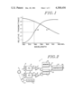
- FIG. 1 shows curves representing the relative transmittance as a function of wavelength of a pair of commercially available optical filters.
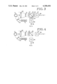
- FIG. 2 is a block diagram of an apparatus according to the present invention.
- FIG. 3 is an alternative embodiment according to the present invention.
- FIG. 4 is a further alternative embodiment according to the present invention.
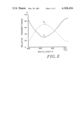
- FIG. 5 shows curves of the relative reflectance and transmittance of a commercially available beam splitter useable in an apparatus as shown in FIG. 4 according to the present invention.
- a pair of curves A and B showing the relative transmittance of a pair of commercially available optical filters as a function of wavelength over a limited portion of the visible spectrum of from 560 to 620 nanometers.
- the curve A a curve of is the relative transmittance of a CM-500 filter.
- the curve B is a curve of the relative transmittance of an 0-58 filter. Both of the filters CM-500 and 0-58 are commercially available from the Hoya Corporation of Palo Alto, California.
- the filters obtained from the Hoya Corporation may be modified slightly by conventional grinding techniques so as to change their response to changes in the wavelength of the radiation transmitted therethrough such that their response is substantially linear over a narrow bandwidth such as, for example, 575-590 nanometers. It will be seen, however, that so long as the ratio of the relative transmittance of the filters for selected wavelengths is unique, the filter characteristics need not necessarily be linear. It will also be appreciated that the same or other filters, such as interference, reflective and absorbing filters, can be used with or without modification to obtain linear as well as non-linear frequency response characteristics over other ranges of wavelengths, depending upon the requirements of a particular application. As indicated, the importance of the curves A and B of FIG.
- a frequency measuring apparatus designated generally as 1.
- the apparatus 1 is provided with a pair of filters 2 and 3.
- the filters 2 and 3 comprise, respectively, the CM-500 and 0-58 filters described above with respect to FIG. 1. They are provided for receiving radiation from a source of emitted, scattered or reflected radiation designated generally as 4.
- the output of photo-detector 5 is coupled to the input of an integrating circuit 7 by means of a line 8.
- the output of the photo-detector 6 is coupled to an integrating circuit 9 by means of a line 10.
- the outputs of the integrating circuits 7 and 9 are coupled to the inputs of a divider circuit 11 by means of a pair of lines 12 and 13.
- the output of the divider circuit 11 is coupled to a comparator circuit 14 by means of a line 15.
- a second input of the comparator circuit 14 is coupled to a memory 16 by means of a line 17.
- the output of the comparator 14 is provided on a line 18.
- radiation having a frequency in the visible spectrum is received from the source 4 by the photodetectors 5 and 6 through the filters 2 and 3.
- the radiation from the source 4 may be emitted, reflected or scattered radiation.
- the magnitude of the radiation received from the source 4 by the photo-detectors 5 and 6 is a function of the transmittance of the filters 2 and 3, respectively.
- the output of filter 2 decreases with increasing wavelength, while the output of filter 3 increases with increasing wavelength in a substantially linear manner over a bandwidth of 575-590 nanometers.
- the outputs of the photo-detectors 5 and 6 will vary in accordance with the transmittance of the filters 2 and 3.
- the outputs of the photo-detectors 5 and 6 are integrated in integrating circuits 7 and 9.
- the outputs of the integrating circuits 7 and 9 are then divided to form a ratio in the divider circuit 11.
- the output of the divider 11 is a value corresponding to a ratio of the transmittance of the filters 2 and 3 at a particular dominant wavelength. As seen in FIG.
- the ratio formed in divider 11 and the output of the divider 11 is a value corresponding to 2. If, in a particular application, it is desirable, the ratio may be inverted and the value at the output of the divider 2 will correspond to 0.5.
- the ratio is generated in the divider 11 it is compared with pre-sorted ratios from the memory 16 in the comparator 14.
- an indication is provided at the output of the comparator 14 on the line 18.
- the indication at the output of the comparator 14 on the line 18 corresponds to the value associated with the matched ratio.
- the corresponding value at the output of the comparator 18 is a number corresponding to the wavelength of the radiation detected. In the example given the radiation detected is 580 nanometers.
- the memory 16 Prior to the use of the apparatus of FIG. 2 to measure the frequency of radiation from the source 4, to obtain the pre-stored ratios, the memory 16 is pre-stored with a plurality of values corresponding to the ratio of the relative transmittance of the filters 2 and 3 for a plurality of pre-selected wavelengths within a predetermined band.
- the number of pre-selected frequencies throughout the band of interest may vary, depending upon the application. Obviously, the greater the number of pre-selected frequencies, the greater is the resolution of the apparatus.
- the comparator 14 For outputs from the divider 11 which do not correspond exactly with a pre-stored value in the memory 16, the comparator 14 still provides an output, but the output of the comparator 14 is provided with an indication that the wavelength detected is approximate.
- a focusing lens 20, a collimating lens 21 and a bandpass or cutoff filter 22 Optically coupled to the filter 22, there is provided a beam splitter 23. Radiation from the beam splitter 23 is passed through a pair of filters 24 and 25 to a pair of photo-detectors 26 and 27, respectively. The outputs of the photo-detectors 26 and 27 are provided on an output line 28 and 29, respectively.
- the output lines 28 and 29 are coupled to a pair of integrating circuits such as integrating circuits 7 and 9 of FIG. 2 and by means of the integrating circuits to a divider, comparator and memory circuit, as described above with respect to FIG. 2.
- the filters 24 and 25 are substantially identical to the filters 2 and 3 described above with respect to FIG. 2 and have relative transmittance characteristics as discussed above with respect to FIG. 1.
- radiation emitted, reflected or scattered from the source 4 is focused by the lens 20 onto the collimating lens 21. It is collimated and directed to the filter 22.
- the filter 22 is a bandpass or cutoff filter provided for blocking non-visible radiation from the beam splitter 23. It may also be of a type used for limiting visible radiation to a selected portion of the visible spectrum.
- the radiation impinging on the beam splitter 23 is partially transmitted and partially reflected in the beam splitter 23 in a conventional manner.
- the transmitted radiation is directed through the filter 25 to the photo-detector circuit 29.
- the reflected radiation is directed through the filter 24 to the photo-detector 26.
- a differential beam splitter 30 replaces in a circuit otherwise substantially identical to the apparatus of FIG. 3 the beam splitter 23 and the filters 24 and 25 of the apparatus of FIG. 3.
- the beam splitter 30 is provided with a differential reflectance and transmittance as represented by the curves designated R and T in the figure. As seen in the figure, from approximately 550-600 nanometers and beyond, the reflectance of the beam splitter 30 decreases with increasing wavelength while the transmittance of the beam splitter 30 increases with increasing wavelength in a manner corresponding to the negative and positive slopes with increasing wavelength of the filters 2 and 3 and 25 and 26 represented by the curves A and B of FIG. 1.
- the apparatus of FIG. 4 is otherwise substantially identical and functions in substantially the same manner as the apparatus of FIG. 3, as described above.
- the apparatus of the present invention is used for measuring the frequency of emitted, scattered and reflected radiation.
- the measurements can be made entirely in the absence of ambient radiation.
- a source of external radiation is required to illuminate the object or surface under test.
- the external source may be a lamp external to the apparatus described herein or a lamp forming an integral part of the apparatus described herein.
- each of the embodiments an internal lamp 40.
- the lamp 40 is preferably a source of broadband or white light, such as obtained from a tungsten filament. Coupled to the lamp 40 there is provided a control circuit 41 for controlling the operation of the lamp.
- the apparatus of the present invention may be used in conjunction with the apparatus disclosed and described in U.S. Pat. No. 4,061,925, issued Dec. 6, 1977 to one of the applicants of the present application and assigned to the assignee of the present application.
- the intensity of the ambient radiation in the absence of radiation from the source under test is determined. Then, the intensity of the ambient radiation, together with radiation from the source under test, is determined. Thereafter, a value corresponding to the intensity of the radiation in the absence of radiation from the device under test, is subtracted from a value corresponding to the intensity of the combined radiation for providing a value corresponding to the intensity of the radiation from the device under test.
Abstract
Description
Claims (19)
Priority Applications (2)
| Application Number | Priority Date | Filing Date | Title |
|---|---|---|---|
| US06/095,639 US4308456A (en) | 1979-11-19 | 1979-11-19 | Method and apparatus for measuring the frequency of radiation |
| PCT/US1980/001549 WO1981001466A1 (en) | 1979-11-19 | 1980-11-18 | A method and apparatus for measuring the frequency of radiation |
Applications Claiming Priority (1)
| Application Number | Priority Date | Filing Date | Title |
|---|---|---|---|
| US06/095,639 US4308456A (en) | 1979-11-19 | 1979-11-19 | Method and apparatus for measuring the frequency of radiation |
Publications (1)
| Publication Number | Publication Date |
|---|---|
| US4308456A true US4308456A (en) | 1981-12-29 |
Family
ID=22252912
Family Applications (1)
| Application Number | Title | Priority Date | Filing Date |
|---|---|---|---|
| US06/095,639 Expired - Lifetime US4308456A (en) | 1979-11-19 | 1979-11-19 | Method and apparatus for measuring the frequency of radiation |
Country Status (2)
| Country | Link |
|---|---|
| US (1) | US4308456A (en) |
| WO (1) | WO1981001466A1 (en) |
Cited By (39)
| Publication number | Priority date | Publication date | Assignee | Title |
|---|---|---|---|---|
| WO1986000420A1 (en) * | 1984-06-25 | 1986-01-16 | Enpece Ab | Method and device for non-contact detection of plants |
| WO1987002765A1 (en) * | 1985-10-25 | 1987-05-07 | Optech Inc. | Controlled color light source |
| US4804833A (en) * | 1985-09-06 | 1989-02-14 | Minolta Camera Kabushiki Kaisha | Color sensing method and device therefor |
| US4878722A (en) * | 1988-06-24 | 1989-11-07 | Korry Electronics Company | Wavelength encoded optical switches |
| US4904088A (en) * | 1984-08-10 | 1990-02-27 | U.S. Philips Corporation | Method and apparatus for determining radiation wavelengths and wavelength-corrected radiation power of monochromatic light sources |
| US4922154A (en) * | 1988-01-11 | 1990-05-01 | Alain Cacoub | Chromatic lighting display |
| US4985622A (en) * | 1988-06-11 | 1991-01-15 | Daimler-Benz Ag | Method for determining the corrosion resistance of deep-drawable iron sheets for body parts of motor vehicles and apparatus for performing the method |
| US5319435A (en) * | 1991-09-04 | 1994-06-07 | Melle Serge M | Method and apparatus for measuring the wavelength of spectrally narrow optical signals |
| US5410412A (en) * | 1990-05-14 | 1995-04-25 | Labintellegence, Inc. | Gel electrophoresis system |
| US5627648A (en) * | 1995-07-12 | 1997-05-06 | Jds Fitel Inc. | Method and apparatus for use in the measurement of the wavelength or frequency of an optical signal |
| US5703357A (en) * | 1993-09-27 | 1997-12-30 | Shih; Ishiang | Methods for wavelength discrimination of monochromatic light beams |
| US5823950A (en) * | 1995-06-07 | 1998-10-20 | Masimo Corporation | Manual and automatic probe calibration |
| US5999271A (en) * | 1998-06-01 | 1999-12-07 | Shih; Ishiang | Methods and devices to determine the wavelength of a laser beam |
| US6002952A (en) * | 1997-04-14 | 1999-12-14 | Masimo Corporation | Signal processing apparatus and method |
| WO2000062027A1 (en) * | 1999-04-12 | 2000-10-19 | Sony Electronics Inc. | Optical sensor, method for the design thereof, and camera using the optical sensor |
| US6252663B1 (en) | 1999-04-12 | 2001-06-26 | Sony Corporation | Scanning and printing systems with color discrimination |
| US6403947B1 (en) | 1999-03-18 | 2002-06-11 | Cambridge Research & Instrumentation Inc. | High-efficiency multiple probe imaging system |
| US6441903B1 (en) | 1999-04-12 | 2002-08-27 | Sony Corporation | Optical sensor for illumination mixtures and method for the design thereof |
| US6819306B1 (en) | 1999-04-12 | 2004-11-16 | Sony Corporation | Color correcting and ambient light responsive CRT system |
| US20050219536A1 (en) * | 2004-03-31 | 2005-10-06 | Mark Feldman | Wavelength detector |
| US7088441B2 (en) | 2002-09-19 | 2006-08-08 | Mitutoyo Corporation | Method and apparatus for measuring wavelength changes in a high-resolution measurement system |
| US20070051881A1 (en) * | 2005-05-20 | 2007-03-08 | Tir Systems Ltd. | Multicolour chromaticity sensor |
| US7245953B1 (en) | 1999-04-12 | 2007-07-17 | Masimo Corporation | Reusable pulse oximeter probe and disposable bandage apparatii |
| US7272425B2 (en) | 1999-12-09 | 2007-09-18 | Masimo Corporation | Pulse oximetry sensor including stored sensor data |
| US20070282478A1 (en) * | 2006-06-05 | 2007-12-06 | Ammar Al-Ali | Parameter upgrade system |
| WO2008009093A1 (en) * | 2006-07-18 | 2008-01-24 | Tir Technology Lp | Method and apparatus for determining intensities and peak wavelengths of light |
| US20090177315A1 (en) * | 2007-12-21 | 2009-07-09 | Georgia-Pacific Consumer Products Lp | Product, Dispenser and Method of Dispensing Product |
| US20090262352A1 (en) * | 2008-04-19 | 2009-10-22 | Frank Trilling | Device for the optical detection of the lateral position of characteristics on traveling material webs and method for operating this device |
| US20090262227A1 (en) * | 2008-04-21 | 2009-10-22 | Shimadzu Corporation | Photodiode array and signal readout method for the same |
| USRE41317E1 (en) | 1998-10-15 | 2010-05-04 | Masimo Corporation | Universal modular pulse oximeter probe for use with reusable and disposable patient attachment devices |
| USRE41912E1 (en) | 1998-10-15 | 2010-11-02 | Masimo Corporation | Reusable pulse oximeter probe and disposable bandage apparatus |
| US7990382B2 (en) | 2006-01-03 | 2011-08-02 | Masimo Corporation | Virtual display |
| WO2013007445A1 (en) * | 2011-07-13 | 2013-01-17 | Osram Ag | Detection device for a projector |
| US8989831B2 (en) | 2009-05-19 | 2015-03-24 | Masimo Corporation | Disposable components for reusable physiological sensor |
| JP2016166797A (en) * | 2015-03-10 | 2016-09-15 | 日置電機株式会社 | Light-amount measurement device |
| US9560998B2 (en) | 2006-10-12 | 2017-02-07 | Masimo Corporation | System and method for monitoring the life of a physiological sensor |
| US9795739B2 (en) | 2009-05-20 | 2017-10-24 | Masimo Corporation | Hemoglobin display and patient treatment |
| US10058275B2 (en) | 2003-07-25 | 2018-08-28 | Masimo Corporation | Multipurpose sensor port |
| US10993643B2 (en) | 2006-10-12 | 2021-05-04 | Masimo Corporation | Patient monitor capable of monitoring the quality of attached probes and accessories |
Families Citing this family (6)
| Publication number | Priority date | Publication date | Assignee | Title |
|---|---|---|---|---|
| FR2676811B1 (en) * | 1991-05-23 | 1993-09-10 | Peugeot | OPTICAL DEVICE FOR RECOGNIZING SHADES OF WINDOWS. |
| GB2269230A (en) * | 1992-07-31 | 1994-02-02 | Sinar Agritec Ltd | Measuring light wavelength. |
| DE19744565C2 (en) * | 1997-10-09 | 2000-02-03 | Zeiss Optronik Gmbh | Wavelength measuring device for short laser pulses |
| GB2345540B (en) * | 1999-01-07 | 2001-03-21 | Infrared Integrated Syst Ltd | Spectrometer/spectrophotometer using multiple filter based detector array |
| US7560685B2 (en) * | 2007-09-14 | 2009-07-14 | Weatherford/Lamb, Inc. | Spectrally stabilized broadband optical source |
| DE102012215702A1 (en) * | 2012-09-05 | 2014-03-06 | Osram Gmbh | lighting device |
Citations (2)
| Publication number | Priority date | Publication date | Assignee | Title |
|---|---|---|---|---|
| US4057352A (en) * | 1976-05-13 | 1977-11-08 | Genevieve I. Hanscom | Color grading apparatus utilizing infrared light source |
| US4057146A (en) * | 1974-05-24 | 1977-11-08 | Xeltron, S.A. | Optical sorting apparatus |
Family Cites Families (1)
| Publication number | Priority date | Publication date | Assignee | Title |
|---|---|---|---|---|
| US3987298A (en) * | 1975-07-09 | 1976-10-19 | Honeywell Inc. | Photodetector system for determination of the wavelength of incident radiation |
-
1979
- 1979-11-19 US US06/095,639 patent/US4308456A/en not_active Expired - Lifetime
-
1980
- 1980-11-18 WO PCT/US1980/001549 patent/WO1981001466A1/en unknown
Patent Citations (2)
| Publication number | Priority date | Publication date | Assignee | Title |
|---|---|---|---|---|
| US4057146A (en) * | 1974-05-24 | 1977-11-08 | Xeltron, S.A. | Optical sorting apparatus |
| US4057352A (en) * | 1976-05-13 | 1977-11-08 | Genevieve I. Hanscom | Color grading apparatus utilizing infrared light source |
Cited By (82)
| Publication number | Priority date | Publication date | Assignee | Title |
|---|---|---|---|---|
| WO1986000420A1 (en) * | 1984-06-25 | 1986-01-16 | Enpece Ab | Method and device for non-contact detection of plants |
| US4904088A (en) * | 1984-08-10 | 1990-02-27 | U.S. Philips Corporation | Method and apparatus for determining radiation wavelengths and wavelength-corrected radiation power of monochromatic light sources |
| US4804833A (en) * | 1985-09-06 | 1989-02-14 | Minolta Camera Kabushiki Kaisha | Color sensing method and device therefor |
| WO1987002765A1 (en) * | 1985-10-25 | 1987-05-07 | Optech Inc. | Controlled color light source |
| US4692607A (en) * | 1985-10-25 | 1987-09-08 | Optech Inc. | Controlled color light source |
| US4922154A (en) * | 1988-01-11 | 1990-05-01 | Alain Cacoub | Chromatic lighting display |
| US4985622A (en) * | 1988-06-11 | 1991-01-15 | Daimler-Benz Ag | Method for determining the corrosion resistance of deep-drawable iron sheets for body parts of motor vehicles and apparatus for performing the method |
| US4878722A (en) * | 1988-06-24 | 1989-11-07 | Korry Electronics Company | Wavelength encoded optical switches |
| US5410412A (en) * | 1990-05-14 | 1995-04-25 | Labintellegence, Inc. | Gel electrophoresis system |
| US5319435A (en) * | 1991-09-04 | 1994-06-07 | Melle Serge M | Method and apparatus for measuring the wavelength of spectrally narrow optical signals |
| US5703357A (en) * | 1993-09-27 | 1997-12-30 | Shih; Ishiang | Methods for wavelength discrimination of monochromatic light beams |
| US6011986A (en) * | 1995-06-07 | 2000-01-04 | Masimo Corporation | Manual and automatic probe calibration |
| US5823950A (en) * | 1995-06-07 | 1998-10-20 | Masimo Corporation | Manual and automatic probe calibration |
| US7526328B2 (en) | 1995-06-07 | 2009-04-28 | Masimo Corporation | Manual and automatic probe calibration |
| US8145287B2 (en) | 1995-06-07 | 2012-03-27 | Masimo Corporation | Manual and automatic probe calibration |
| EP1238627A2 (en) * | 1995-06-07 | 2002-09-11 | Masimo Corporation | Medical sensor and information system |
| US6678543B2 (en) | 1995-06-07 | 2004-01-13 | Masimo Corporation | Optical probe and positioning wrap |
| EP1238627A3 (en) * | 1995-06-07 | 2003-01-15 | Masimo Corporation | Medical sensor and information system |
| US7496391B2 (en) | 1995-06-07 | 2009-02-24 | Masimo Corporation | Manual and automatic probe calibration |
| US6397091B2 (en) | 1995-06-07 | 2002-05-28 | Masimo Corporation | Manual and automatic probe calibration |
| US8781543B2 (en) | 1995-06-07 | 2014-07-15 | Jpmorgan Chase Bank, National Association | Manual and automatic probe calibration |
| US5627648A (en) * | 1995-07-12 | 1997-05-06 | Jds Fitel Inc. | Method and apparatus for use in the measurement of the wavelength or frequency of an optical signal |
| US8888708B2 (en) | 1997-04-14 | 2014-11-18 | Masimo Corporation | Signal processing apparatus and method |
| US8180420B2 (en) | 1997-04-14 | 2012-05-15 | Masimo Corporation | Signal processing apparatus and method |
| US6067462A (en) * | 1997-04-14 | 2000-05-23 | Masimo Corporation | Signal processing apparatus and method |
| US6699194B1 (en) | 1997-04-14 | 2004-03-02 | Masimo Corporation | Signal processing apparatus and method |
| US9289167B2 (en) | 1997-04-14 | 2016-03-22 | Masimo Corporation | Signal processing apparatus and method |
| US6002952A (en) * | 1997-04-14 | 1999-12-14 | Masimo Corporation | Signal processing apparatus and method |
| US8190227B2 (en) | 1997-04-14 | 2012-05-29 | Masimo Corporation | Signal processing apparatus and method |
| US5999271A (en) * | 1998-06-01 | 1999-12-07 | Shih; Ishiang | Methods and devices to determine the wavelength of a laser beam |
| US8706179B2 (en) | 1998-10-15 | 2014-04-22 | Masimo Corporation | Reusable pulse oximeter probe and disposable bandage apparatii |
| USRE43860E1 (en) | 1998-10-15 | 2012-12-11 | Masimo Corporation | Reusable pulse oximeter probe and disposable bandage apparatus |
| USRE43169E1 (en) | 1998-10-15 | 2012-02-07 | Masimo Corporation | Universal modular pulse oximeter probe for use with reusable and disposable patient attachment devices |
| USRE41912E1 (en) | 1998-10-15 | 2010-11-02 | Masimo Corporation | Reusable pulse oximeter probe and disposable bandage apparatus |
| USRE41317E1 (en) | 1998-10-15 | 2010-05-04 | Masimo Corporation | Universal modular pulse oximeter probe for use with reusable and disposable patient attachment devices |
| USRE44823E1 (en) | 1998-10-15 | 2014-04-01 | Masimo Corporation | Universal modular pulse oximeter probe for use with reusable and disposable patient attachment devices |
| US6403947B1 (en) | 1999-03-18 | 2002-06-11 | Cambridge Research & Instrumentation Inc. | High-efficiency multiple probe imaging system |
| US8175672B2 (en) | 1999-04-12 | 2012-05-08 | Masimo Corporation | Reusable pulse oximeter probe and disposable bandage apparatii |
| WO2000062027A1 (en) * | 1999-04-12 | 2000-10-19 | Sony Electronics Inc. | Optical sensor, method for the design thereof, and camera using the optical sensor |
| US6252663B1 (en) | 1999-04-12 | 2001-06-26 | Sony Corporation | Scanning and printing systems with color discrimination |
| US6441903B1 (en) | 1999-04-12 | 2002-08-27 | Sony Corporation | Optical sensor for illumination mixtures and method for the design thereof |
| US6819306B1 (en) | 1999-04-12 | 2004-11-16 | Sony Corporation | Color correcting and ambient light responsive CRT system |
| US7245953B1 (en) | 1999-04-12 | 2007-07-17 | Masimo Corporation | Reusable pulse oximeter probe and disposable bandage apparatii |
| US7272425B2 (en) | 1999-12-09 | 2007-09-18 | Masimo Corporation | Pulse oximetry sensor including stored sensor data |
| US7088441B2 (en) | 2002-09-19 | 2006-08-08 | Mitutoyo Corporation | Method and apparatus for measuring wavelength changes in a high-resolution measurement system |
| US11020029B2 (en) | 2003-07-25 | 2021-06-01 | Masimo Corporation | Multipurpose sensor port |
| US10058275B2 (en) | 2003-07-25 | 2018-08-28 | Masimo Corporation | Multipurpose sensor port |
| US7253902B2 (en) | 2004-03-31 | 2007-08-07 | Mitutoyo Corporation | Wavelength detector |
| US20050219536A1 (en) * | 2004-03-31 | 2005-10-06 | Mark Feldman | Wavelength detector |
| EP1886104A4 (en) * | 2005-05-20 | 2011-11-16 | Koninkl Philips Electronics Nv | Multicolour chromaticity sensor |
| US7388665B2 (en) | 2005-05-20 | 2008-06-17 | Tir Technology Lp | Multicolour chromaticity sensor |
| EP1886104A1 (en) * | 2005-05-20 | 2008-02-13 | Tir Systems Ltd. | Multicolour chromaticity sensor |
| US20070051881A1 (en) * | 2005-05-20 | 2007-03-08 | Tir Systems Ltd. | Multicolour chromaticity sensor |
| US7990382B2 (en) | 2006-01-03 | 2011-08-02 | Masimo Corporation | Virtual display |
| US10188348B2 (en) | 2006-06-05 | 2019-01-29 | Masimo Corporation | Parameter upgrade system |
| US20070282478A1 (en) * | 2006-06-05 | 2007-12-06 | Ammar Al-Ali | Parameter upgrade system |
| US11191485B2 (en) | 2006-06-05 | 2021-12-07 | Masimo Corporation | Parameter upgrade system |
| US20090303467A1 (en) * | 2006-07-18 | 2009-12-10 | Ian Ashdown | Method and apparatus for determining intensities and peak wavelengths of light |
| WO2008009093A1 (en) * | 2006-07-18 | 2008-01-24 | Tir Technology Lp | Method and apparatus for determining intensities and peak wavelengths of light |
| US7894050B2 (en) | 2006-07-18 | 2011-02-22 | Koninklijke Philips Electronics N.V. | Method and apparatus for determining intensities and peak wavelengths of light |
| US9560998B2 (en) | 2006-10-12 | 2017-02-07 | Masimo Corporation | System and method for monitoring the life of a physiological sensor |
| US11857315B2 (en) | 2006-10-12 | 2024-01-02 | Masimo Corporation | Patient monitor capable of monitoring the quality of attached probes and accessories |
| US11857319B2 (en) | 2006-10-12 | 2024-01-02 | Masimo Corporation | System and method for monitoring the life of a physiological sensor |
| US10863938B2 (en) | 2006-10-12 | 2020-12-15 | Masimo Corporation | System and method for monitoring the life of a physiological sensor |
| US10993643B2 (en) | 2006-10-12 | 2021-05-04 | Masimo Corporation | Patient monitor capable of monitoring the quality of attached probes and accessories |
| US10039482B2 (en) | 2006-10-12 | 2018-08-07 | Masimo Corporation | System and method for monitoring the life of a physiological sensor |
| US11317837B2 (en) | 2006-10-12 | 2022-05-03 | Masimo Corporation | System and method for monitoring the life of a physiological sensor |
| US10342470B2 (en) | 2006-10-12 | 2019-07-09 | Masimo Corporation | System and method for monitoring the life of a physiological sensor |
| US20090177315A1 (en) * | 2007-12-21 | 2009-07-09 | Georgia-Pacific Consumer Products Lp | Product, Dispenser and Method of Dispensing Product |
| US20090262352A1 (en) * | 2008-04-19 | 2009-10-22 | Frank Trilling | Device for the optical detection of the lateral position of characteristics on traveling material webs and method for operating this device |
| US20090262227A1 (en) * | 2008-04-21 | 2009-10-22 | Shimadzu Corporation | Photodiode array and signal readout method for the same |
| US8194161B2 (en) * | 2008-04-21 | 2012-06-05 | Shimadzu Corporation | Photodiode array and signal readout method for the same |
| US8989831B2 (en) | 2009-05-19 | 2015-03-24 | Masimo Corporation | Disposable components for reusable physiological sensor |
| US10342487B2 (en) | 2009-05-19 | 2019-07-09 | Masimo Corporation | Disposable components for reusable physiological sensor |
| US9895107B2 (en) | 2009-05-19 | 2018-02-20 | Masimo Corporation | Disposable components for reusable physiological sensor |
| US11331042B2 (en) | 2009-05-19 | 2022-05-17 | Masimo Corporation | Disposable components for reusable physiological sensor |
| US10413666B2 (en) | 2009-05-20 | 2019-09-17 | Masimo Corporation | Hemoglobin display and patient treatment |
| US10953156B2 (en) | 2009-05-20 | 2021-03-23 | Masimo Corporation | Hemoglobin display and patient treatment |
| US9795739B2 (en) | 2009-05-20 | 2017-10-24 | Masimo Corporation | Hemoglobin display and patient treatment |
| US11752262B2 (en) | 2009-05-20 | 2023-09-12 | Masimo Corporation | Hemoglobin display and patient treatment |
| WO2013007445A1 (en) * | 2011-07-13 | 2013-01-17 | Osram Ag | Detection device for a projector |
| JP2016166797A (en) * | 2015-03-10 | 2016-09-15 | 日置電機株式会社 | Light-amount measurement device |
Also Published As
| Publication number | Publication date |
|---|---|
| WO1981001466A1 (en) | 1981-05-28 |
Similar Documents
| Publication | Publication Date | Title |
|---|---|---|
| US4308456A (en) | Method and apparatus for measuring the frequency of radiation | |
| US5844680A (en) | Device and process for measuring and analysing spectral radiation, in particular for measuring and analysing color characteristics | |
| US2474098A (en) | Photometric measurement of light values using automatic gain control in photomultiplier tubes | |
| JPS61116646A (en) | Fluorophotometer and method of measuring fluorescence | |
| KR20020016843A (en) | Color display | |
| US2686452A (en) | Color matching apparatus | |
| US6631000B1 (en) | Device and procedure for the quality control of in particular finished surfaces | |
| US2382439A (en) | Color grading apparatus and method | |
| US4295042A (en) | Method of and device for measuring chlorophyll of living leaves | |
| EP0169664B1 (en) | Apparatus for determining the degree of oxidation of an oxide coating | |
| US2218253A (en) | Method and means for measuring color | |
| US3491243A (en) | Authentication apparatus to measure color characteristics of paper documents | |
| US2720811A (en) | Tristimulus photometer | |
| US3529895A (en) | Automatic limit colorimeter | |
| JPS6257533A (en) | Anomaloscope for examining color sense of human | |
| SERIKAWA et al. | Improvement of the instrument for measuring glossiness of curved surfaces | |
| US2759392A (en) | Color temperature meter and color analyzer | |
| US20080273204A1 (en) | Apparatus and Method for Measuring the Spectral Properties of a Fluid | |
| US3634694A (en) | Programmed-response spectral scanning telephotometer system | |
| Wagner | Simulation of system transmission values for different angles of incidence | |
| US3525572A (en) | Adjustable scale colorimeter | |
| US2435175A (en) | Flickering beam spectrophotometer for the measurement of bronze | |
| WO1995020758A1 (en) | Measuring instrument for reflectometric measurements | |
| Michaelson | Color measurements | |
| SU958924A1 (en) | Rice grain checking quality method |
Legal Events
| Date | Code | Title | Description |
|---|---|---|---|
| AS | Assignment |
Owner name: VERSATILE INTEGRATED MODULES, 1283-A MOUNTAIN VIEW Free format text: ASSIGNMENT OF ASSIGNORS INTEREST.;ASSIGNORS:VAN DER GAAG LEONARD C.;HOOKER ALLEN;REEL/FRAME:003885/0991 Effective date: 19810727 Owner name: VAN DER GAAG,LEONARD C. SAN JOSE, CA. Free format text: ASSIGNMENT OF ASSIGNORS INTEREST.;ASSIGNOR:PUETZ GERALD;REEL/FRAME:003885/0993 Effective date: 19791106 Owner name: HOOKER, ALLEN , SAN JOSE, CA. Free format text: ASSIGNMENT OF ASSIGNORS INTEREST.;ASSIGNOR:PUETZ GERALD;REEL/FRAME:003885/0993 Effective date: 19791106 Owner name: VAN DER GAAG,LEONARD C., CALIFORNIA Free format text: ASSIGNMENT OF ASSIGNORS INTEREST;ASSIGNOR:PUETZ GERALD;REEL/FRAME:003885/0993 Effective date: 19791106 Owner name: HOOKER, ALLEN, CALIFORNIA Free format text: ASSIGNMENT OF ASSIGNORS INTEREST;ASSIGNOR:PUETZ GERALD;REEL/FRAME:003885/0993 Effective date: 19791106 |
|
| STCF | Information on status: patent grant |
Free format text: PATENTED CASE |