US2544036A - Cotton chopper - Google Patents
Cotton chopper Download PDFInfo
- Publication number
- US2544036A US2544036A US696061A US69606146A US2544036A US 2544036 A US2544036 A US 2544036A US 696061 A US696061 A US 696061A US 69606146 A US69606146 A US 69606146A US 2544036 A US2544036 A US 2544036A
- Authority
- US
- United States
- Prior art keywords
- flywheel
- plant
- chopper
- pin
- trigger
- Prior art date
- Legal status (The legal status is an assumption and is not a legal conclusion. Google has not performed a legal analysis and makes no representation as to the accuracy of the status listed.)
- Expired - Lifetime
Links
Images


Classifications
-
- A—HUMAN NECESSITIES
- A01—AGRICULTURE; FORESTRY; ANIMAL HUSBANDRY; HUNTING; TRAPPING; FISHING
- A01B—SOIL WORKING IN AGRICULTURE OR FORESTRY; PARTS, DETAILS, OR ACCESSORIES OF AGRICULTURAL MACHINES OR IMPLEMENTS, IN GENERAL
- A01B41/00—Thinning machines
- A01B41/04—Thinning machines with rotating tools
Definitions
- This invention relates ⁇ to agricultural machinery, especially to those adapted to thin out plants planted in rows, and more especially to those machines known as cotton choppers. ⁇
- the objects of my invention are to provide a machine which will hoe out every plant except one in arow every predetermined number of inches, leaving a row of evenly spaced plants undisturbed; which will operate when the plants are small; which will operate equally well when the plants are well grown; which may be operated over the same row a plurality of times and will always leave the same plants standing; which may be turned around and operated in the reverse direction over the same row and will again leave the same plants undisturbed; to which suitable cultivators or other soil conditioning tools may be attached for simultaneous action on the soil between the rows.
- a further object is to provide a machine which is of simple, rugged construction, of high emciency, of low cost and easy to keep in repair and in which the operator is only required to steer and generally oversee the machine as it automatically performs the work required.
- a further object is to provide a machine which operates in proportion to the size of the chopping hoe and is not dependent on the speed of travel of the machine nor on the distance traveled thereby.
- An additional object is to provide a machine which is controlled by the first plant met after the hoe has acted to eradicate the previously met plants, leaving such plant undisturbed, in other words, if there is an empty space Vin a row, the machine does not act until the next planty is reached when it acts to miss such first plant and destroy the next plants within the space swept by the hoe.
- Fig. 1 is a plan of my improved cotton chopper
- Fig. 2 is a vertical longitudinal section thereof, taken on the line 2 2 in Fig. 1
- Fig. 3 is a front elevation of the chopper disk and its hoes, in its normal static position
- Fig. 4 is a vertical longitudinal section of the operating mechanism
- Fig. 5 is a plan of one of the hoe blades;
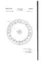
- Fig. 6 is an elevation of the front side of the flywheel;
- Fig. 7 is a vertical longitudinal section of a portion of the ywheel and the adjacent chopper disk, showing the mechanism adapted to connect the two parts together, in its withdrawn position permitting the ywheel to rotate without moving the chopper disk;
- Fig. 8 is a similar view showing the same mechanism in its active position;
- Fig. 9 is a plan of one of the hoe blades;
- Fig. 10 is a side 'elevation thereof; Figs. 11 and 12, 13 and 14, 15 and 16 are, respectively, side views and plans of the three forms of trigger connections with the chopper control mechanism.
- of my improved cotton chopper comprises two parallel side frame members 22 joined by a front member 23 and a rear member 24.
- a seat member 25 extends across the frame, over the axle, with a suitable seat for the machine operator.
- a front cross member 23 is mounted between the side members 22 and is adapted to receive bearings for the countershaft and operating shaft, hereinafter described, and a second cross member 2l is similarly mounted parallel with and slightly to the rear of said cross member 26, and is adapted to hold the bearing of the countershaft.
- is mounted on two main rear wheels 28 and these Wheels are suitably secured to and rotate the main shaft 28.
- is supported on a bogie truck 30, pivotally secured under the center of the front member 23, and provided with two side wheels 3
- the truck 30 is controlled on its pivot by the handle 32 extending rearward therefrom to a position adjacent to the operator, for steering the machine.
- a large bevel gear wheel 33 is sldably mounted on the shaft 29, driven by the main wheels 28,
- This bevel gear 35 is secured to the rear end of the countershaft 36.
- This countershaft 36 is mounted in bearings 3l on the two above del scribed cross members 26 and 21, and is provided,
- This gear 38 meshes with a small gear wheel 39 which is mounted on the rear end of the operating shaft 46.
- This shaft 40 is mounted in bearings 4
- the ratios of gears 33-35 and 38-39 are such as to multiply the rate of rotation of the operating shaft 48,.
- the flywheel 42 which is mounted upon the shaft 46 and rotates therewith, therefore, turns at a high rate and absorbs momentum as it is rotated, and this momentum supplies the operating force to turn the hereinafter described chopping disk against the resistance of the ground being hoed.
- This flywheel is provided with a plurality of holes 43 (twenty-one are shown in Fig. 6) equally spaced around its central axis and each parallel to said axis. These holes 43 are positioned near the periphery of the flywheel.
- An annular groove 44 is made in the front face of the ilywheel, and these holes 43 all open into said groove.
- a plate 45 is secured to the rear side of the flywheel 42 and is provided with holes therein corresponding with, but smaller than the holes 43, said holes being normally closed by plugs screwed therein.
- Each hole 43 is of two diameters, the front end thereof being smaller than the major portion of the hole, thus leaving a shoulder at the front end.
- a pin 46 is mounted in each said hole 43 and is of such diameter as to pass freely through the smaller end thereof.
- This pin 46 is provided with a circular Bange 41 surrounding its mid section and limiting the outward motion of the pin 46 by its engagement with the above described shoulder in the hole.
- a light spring 48 is mounted around the inner end of the pin 46 between said ange 41 and the rear plate 45, urging the pin outward when the pin is free to move.
- Control Vmembers 49 are mounted in the annular groove 44, adjacent to each said hole 43, and each is adapted to normally cover or block said hole in order to retain the pin 49 in its withdrawn or restrained position in the hole.
- Each member 49 is xedly mounted on a pivot rod 50 passing through and adapted to turn in a hole 5I through the flywheel 42 and positioned adjacent to and parallel with the hole 43, and this rod 55 is provided with an operating lever 52 extending at right angles to the rod 50 and lying close to the rear face of the ywheel 42.
- a bifurcated bracket 53 is mounted on and eX- tends downward from the front cross member 26 of the frame 2l, to a point close to the lowermost edge of the flywheel 42.
- This bracket 53 is provided with a horizontal pivot pin 54, which supports a light trigger.
- This trigger comprisesp a long arm 55, extending down to a point just above the soil and adapted to engage the rst cotton plant which has been left in the row.
- the other end of the trigger comprises a head 56 extending adjacent to, but not normally touching, the above described levers 52 as they pass.
- the trigger arm 55 engages the cotton plant 51, it is turned on the pivot pin 54, thus moving the head 56 into the path of the levers 52 so that the first lever to reach the head 56 is moved backward (relatively to the flywheel) and the pin 46 therein is thrust out therefrom as above described.
- the trigger is of light construction and moves easily when engaged by the plant 51, but the pivot action is somewhat restricted by friction so that uneven motion of the machine will not cause the trigger to swing and unintentionally engage the lever 52.
- a sleeve S is xedly secured to the front member 23 of the frame 2l and extends rearwardly therefrom around the above described operating shaft 46.
- a chopper disk 59 is mounted on the rear end of the sleeve 59.
- An adjustable friction bearing 69 is mounted between the boss 6l of the disk 59 and the sleeve 58, to resist the free motion of the disk on the sleeve.
- the chopper disk 59 is provided with five hoe arms 62 extending therefrom at equally spaced intervals, and each arm is provided with a hoe blade 63, removably secured thereto.
- the hoe blades 63 are nat and have a straight cutting edge and, in plan, are substantially triangular, the apex of the triangle being forward and the cutting edge being substantially parallel with the direction of motion of the machine.
- the chopper disk 59 is provided with ve operating holes 64, arranged at equal distances from the center of the disk and equally spaced from each other. These holes 64 are arcuate and oblong in form and their central radii are equal to the central radii of the above described pins 45in the flywheel 42.
- the rear face of the chopper disk 59 is immediately adjacent to the front face of the flywheel, so that when one of the pins 46 is released and flies out from its hole it immediately enters the next hole 64 in the chopper disk and passes to its ⁇ far end, as the pin is passing outward under the action of the spring 48, engaging the end of the hole 64 and forcibly causing the disk 59, with its hoes 63 to turn on the sleeve 58 until the pin 46 is removed from the hole 64.
- a nxed spring 65 is secured to the sleeve 59 and extends to the face of the chopper disk 59, exerting a strong pressure thereagainst.
- the tip 66 of this spring 65 is bent towards the disk 59 and is positioned so as to enter the hole 64, in which the pin 46 is acting at the moment when the following hoe has reached its normal static position, namely, when the disk 59 has made one-lifth of a revolution under the impulse oi the iiywheel 42.
- the trigger arm 55 When the plants 51 are small and tender I prefer to use the above described trigger arm 55 but if they are strong and somewhat stiff, the arm 55 would have to climb over them as the machine advanced, thus holding the trigger head 55 forward too long, causing the chopper disk to continue to turn more than one-fth of a turn and cutting out too many plants in the row. For this cause I provide another form of trigger when larger plants are to be thinned.
- This device is illustrated in Figs. 9 and l0.
- the trigger comprises a horizontal arm 68 extending from a vertical rod 69 mounted in bearings on a bracket 10, extending down from the rear cross member 2S of the frame 2
- This vertical rod 6S- carries a bevel gear "H.
- a second bracket 'I2 depends from the cross member 2 6 adjacent to the bracket li).
- a horizontal rod is mounted in a bearing at the end of the bracket l2 and carries at one end a bevel gear 73 which meshes with the above gear ll.
- the other end of the horizontal rod is bent at right angles to form an arm M
- This arm "le is positioned in such relation to the flywheel ft2 that normally it hangs down well away from it, but when the plant 5l turns the arm 53 and the parts 69, il and T3, the arm 'le is raised and lies in the path of the levers 52 to release the pin et as above described.
- Figs. l1 and l2 are shown the details of the trigger 5:5, 56, in which the end of the bracket 53 is forked and the pivot 54 passes through both tines.
- the pivot 54 is screw-threaded to control the friction of the trigger against the tines of the bracket.
- the trigger arm 15 which corresponds to the arm 55, is mounted on a horizontal pivot pin iii which is eccentrically placed in the circular head l?. This head engages a horizontal pin 18 to push it out, against the action of a spring I9, and into the path of the levers 52 as they pass.
- the trigger arm 89 is similarly mounted on a pivot pin 3l, which passes through the circular head 82, having gear teeth 83 thereon.
- Another pin 84 is mounted parallel to the pin Si and has a gear Wheel 95 meshing with the teeth 83.
- An arm 36 extends from the gear Wheel 8b and normally is removed from the path of the levers 52 on the yflywheel l2 but is raised to engage such a lever when the arm 36 is moved by engagement with the plant 57.
- a wheeled vehicle spanning the row of plants to be thinned; a shaft driven by the movement of said vehicle; a flywheel mounted on said shaft; a rotary chopper disk mounted con@ centrically with said shaft, in front of said flywheel but disconnected therefrom, and having plant choppers 4mounted thereon; a series of spring actuated pins mounted in said flywheel; openings in said chopperdisk in coordinated position with said pins, and adapted to be successively engaged by one of said pins, to temporarily lock said chopper disk to said flywheel; restraining members normally holding said pins in withdrawn positions; levers on the rear side of said flywheel and connected to and adapted to turn said restraining members out of normal restraining positions; a trigger mounted on said vehicle, to therear of said flywheel, and depending therefrom to engage a plant in the row and to be moved thereby to .engage and turn one said lever as it passes; and a fixed spring pressing on said said
- a wheeled vehicle having a shaft rapidly rotated by the movement of the vehicle, a flywheel mounted on the shaft, and a chopper disk mounted concentrically with said shaft, in front of said flywheel but disconnected therefrom, and having plant choppers mounted thereon; in combination with means to momentarily connect the flywheel with the chopper disk; a trigger mounted on said vehicle, to the rear of said flywheel, and depending therefrom to engage a plant to the rear of the plant choppers, and adapted to be moved as the vehicle advances; means adapted to normally block said connecting means from action; and means adapted to Ibe engaged by said trigger, when moved by the plant, to remove said blocking means, whereby the chopper disk is actuated by said flywheel.
- a machine of the class described comprising a wheeled vehicle having a shaft rapidly rotated by the movement of the vehicle, a flywheel mounted on the shaft, and a chopper disk mounted concentrically with said shaft, in front of said flywheel but disconnected therefrom, and having plant choppers mounted thereon; in combination with means to momentarily connect the flywheel with the chopper disk; a trigger mounted on said vehicle, to the rear of said flywheel, and depending therefrom to engage a plant to the rear of the plant choppers, and adapted to be moved as the vehicle advances; means adapted to normally block said connecting means from acy tion; means adapted to be engaged by said trigger, when moved by the plant, to remove said blocking means, whereby the chopper disk is actuated by said flywheel; and a spring engaging said chopper disk and adapted to disconnect said chopper disk from said flywheel when the chopper disk has moved a predetermined amount to stop the rotation thereof, and whereby said blocking means is restored to blocking position.
- a machine of the class described the combination with a wheeled vehicle; a rotary body mounted in said vehicle and having hoe arms extending therefrom and adapted to chop out some of the plants in a row; a flywheel driven by said wheeled vehicle at a high rate; pins mounted on said flywheel and adapted to engage said rotary body to rotate it, but normally restrained from such engagement; control members mounted on said flywheel and each adapted to restrain said pins from engagement with said rotary body; and a ⁇ pivoted arm adapted to engage a plant of said row and thereby withdraw one said control member from a pin, thereby connecting said rotary body with said flywheel.
- a machine of the class described the combination with a wheeled vehicle; a rotary body mounted in said vehicle and having hoe arms extending therefrom adapted to chop out some of the plants in a row; a flywheel driven by said vehicle at a high rate; pins mounted on said flywheel and adapted to temporarily engage said rotary body to start the rotation thereof y,by the momentum of said flywheel; control members mounted on said flywheel, each said member con- 7; trolling one said pin to restrain the pin from engagement with the rotary body; a pivoted arm adapted to engage a plant of said row and thereby Withdraw one said control member from its restraining position of one pin, thereby connecting said rotary body with said flywheel; and a spring adapted to engage said pin to disconnect the rotary body from the flywheel, to stop the motion of the rotary body, and to restore the control member to its restraining position.
Description
March 6, 1951 E, M MccANN 2,544,036
COTTON CHOPPER IN V EN TOR.
March 6, 19'51 E. M. MCCANN 2,544,036
COTTON CHOPPER Filed Sept. l0, 1946 '7 Sheets-Sheet 2 Edward/M /l76Cd/7/7 INVENTOR ATTORNEY March 6, 1951 E. M. MGCANN 2,544,036
COTTON CHOPPER Filed Sept. 10, 1946 7 Sheets-Sheet 3 INVENTOR BY jf@ ATTORNEY 'March 6, 1951 E. M. MCCANN 2,544,036
COTTON CHOPPER Filed Sept. l0, 1946 '7 Sheets-Sheet 4 fafa/afd M c c7/7n l N V EN TOR.
BY if@ March 6, 1951 E. M. MCCANN 2,544,036
COTTON CHOPPER Filed Sept. lO, 1946 7 Sheets-Sheet 5 Edward M Mc ann INVENTOR 44 L45 ATTORNEY E. M. MCCANN COTTON CHOPPER March 6, 1951 '7 Sheets-Sheet 6 Filed Sept. l0, 1946 EF: ww
n. 6N M H i t d t a .w
ffm
March 6, 1951 E. M. MCCANN 2,544,036
' coTToN CHOPPER Filed Sepc. l0, 1946 7 Sheets-Sheet 7 Fig. I4.
Flug- I6.
[da/ara /I /176 @im NVENTOR.
I f'- BY Patented Mar. 6, 1695i UNITED STATES PATENT OFFICE COTTON CHOPPER Edward M. McCann, Tacoma, Wash.
Application September l0, 1946, Serial No. 696,061
(Cl. {J7-15) 6 Claims.
This invention relates `to agricultural machinery, especially to those adapted to thin out plants planted in rows, and more especially to those machines known as cotton choppers.\
The objects of my invention are to provide a machine which will hoe out every plant except one in arow every predetermined number of inches, leaving a row of evenly spaced plants undisturbed; which will operate when the plants are small; which will operate equally well when the plants are well grown; which may be operated over the same row a plurality of times and will always leave the same plants standing; which may be turned around and operated in the reverse direction over the same row and will again leave the same plants undisturbed; to which suitable cultivators or other soil conditioning tools may be attached for simultaneous action on the soil between the rows. Further objects are to provide a machine which is of simple, rugged construction, of high emciency, of low cost and easy to keep in repair and in which the operator is only required to steer and generally oversee the machine as it automatically performs the work required. A further object is to provide a machine which operates in proportion to the size of the chopping hoe and is not dependent on the speed of travel of the machine nor on the distance traveled thereby. An additional object is to provide a machine which is controlled by the first plant met after the hoe has acted to eradicate the previously met plants, leaving such plant undisturbed, in other words, if there is an empty space Vin a row, the machine does not act until the next planty is reached when it acts to miss such first plant and destroy the next plants within the space swept by the hoe.
' I attain these and other objects by the devices and arrangements illustrated in the accompanying drawings, in which- Fig. 1 is a plan of my improved cotton chopper; Fig. 2 is a vertical longitudinal section thereof, taken on the line 2 2 in Fig. 1; Fig. 3 is a front elevation of the chopper disk and its hoes, in its normal static position; Fig. 4 is a vertical longitudinal section of the operating mechanism; Fig.
5 is a plan of one of the hoe blades; Fig. 6 is an elevation of the front side of the flywheel; Fig. 7 is a vertical longitudinal section of a portion of the ywheel and the adjacent chopper disk, showing the mechanism adapted to connect the two parts together, in its withdrawn position permitting the ywheel to rotate without moving the chopper disk; Fig. 8 is a similar view showing the same mechanism in its active position; Fig. 9
is a front View of a form of the trigger adapted for use in larger plants, and Fig. 10 is a side 'elevation thereof; Figs. 11 and 12, 13 and 14, 15 and 16 are, respectively, side views and plans of the three forms of trigger connections with the chopper control mechanism.
Similar numerals of reference refer to similar parts throughout the several views.
Referring to the drawings, it will be seen in Fig. 1 that the frame 2| of my improved cotton chopper comprises two parallel side frame members 22 joined by a front member 23 and a rear member 24. A seat member 25 extends across the frame, over the axle, with a suitable seat for the machine operator. Also a front cross member 23 is mounted between the side members 22 and is adapted to receive bearings for the countershaft and operating shaft, hereinafter described, and a second cross member 2l is similarly mounted parallel with and slightly to the rear of said cross member 26, and is adapted to hold the bearing of the countershaft.
This frame 2| is mounted on two main rear wheels 28 and these Wheels are suitably secured to and rotate the main shaft 28. The front of the frame 2| is supported on a bogie truck 30, pivotally secured under the center of the front member 23, and provided with two side wheels 3|, whichspan the row of plants to be thinned. The truck 30 is controlled on its pivot by the handle 32 extending rearward therefrom to a position adjacent to the operator, for steering the machine.
A large bevel gear wheel 33 is sldably mounted on the shaft 29, driven by the main wheels 28,
and is controlled in'its position by the handle bar 34, so as to be thrown into or out of mesh with the complementary small bevel gear 35.
This bevel gear 35 is secured to the rear end of the countershaft 36. This countershaft 36 is mounted in bearings 3l on the two above del scribed cross members 26 and 21, and is provided,
. at a point between said bearings 3l, with a large gear wheelh33 secured thereon.
This gear 38 meshes with a small gear wheel 39 which is mounted on the rear end of the operating shaft 46. This shaft 40 is mounted in bearings 4| secured substantially in the centers of the front cross member 26 and the front member 23 of the frame 2|.
The ratios of gears 33-35 and 38-39 are such as to multiply the rate of rotation of the operating shaft 48,. The flywheel 42, which is mounted upon the shaft 46 and rotates therewith, therefore, turns at a high rate and absorbs momentum as it is rotated, and this momentum supplies the operating force to turn the hereinafter described chopping disk against the resistance of the ground being hoed.
This flywheel is provided with a plurality of holes 43 (twenty-one are shown in Fig. 6) equally spaced around its central axis and each parallel to said axis. These holes 43 are positioned near the periphery of the flywheel. An annular groove 44 is made in the front face of the ilywheel, and these holes 43 all open into said groove. A plate 45 is secured to the rear side of the flywheel 42 and is provided with holes therein corresponding with, but smaller than the holes 43, said holes being normally closed by plugs screwed therein. Each hole 43 is of two diameters, the front end thereof being smaller than the major portion of the hole, thus leaving a shoulder at the front end.
A pin 46 is mounted in each said hole 43 and is of such diameter as to pass freely through the smaller end thereof. This pin 46 is provided with a circular Bange 41 surrounding its mid section and limiting the outward motion of the pin 46 by its engagement with the above described shoulder in the hole. A light spring 48 is mounted around the inner end of the pin 46 between said ange 41 and the rear plate 45, urging the pin outward when the pin is free to move.
A bifurcated bracket 53 is mounted on and eX- tends downward from the front cross member 26 of the frame 2l, to a point close to the lowermost edge of the flywheel 42. This bracket 53 is provided with a horizontal pivot pin 54, which supports a light trigger. This trigger comprisesp a long arm 55, extending down to a point just above the soil and adapted to engage the rst cotton plant which has been left in the row. The other end of the trigger comprises a head 56 extending adjacent to, but not normally touching, the above described levers 52 as they pass. However, when the trigger arm 55 engages the cotton plant 51, it is turned on the pivot pin 54, thus moving the head 56 into the path of the levers 52 so that the first lever to reach the head 56 is moved backward (relatively to the flywheel) and the pin 46 therein is thrust out therefrom as above described. The trigger is of light construction and moves easily when engaged by the plant 51, but the pivot action is somewhat restricted by friction so that uneven motion of the machine will not cause the trigger to swing and unintentionally engage the lever 52.
A sleeve S is xedly secured to the front member 23 of the frame 2l and extends rearwardly therefrom around the above described operating shaft 46. A chopper disk 59 is mounted on the rear end of the sleeve 59. An adjustable friction bearing 69 is mounted between the boss 6l of the disk 59 and the sleeve 58, to resist the free motion of the disk on the sleeve.
The chopper disk 59 is provided with five hoe arms 62 extending therefrom at equally spaced intervals, and each arm is provided with a hoe blade 63, removably secured thereto. The hoe blades 63 are nat and have a straight cutting edge and, in plan, are substantially triangular, the apex of the triangle being forward and the cutting edge being substantially parallel with the direction of motion of the machine.
The chopper disk 59 is provided with ve operating holes 64, arranged at equal distances from the center of the disk and equally spaced from each other. These holes 64 are arcuate and oblong in form and their central radii are equal to the central radii of the above described pins 45in the flywheel 42. The rear face of the chopper disk 59 is immediately adjacent to the front face of the flywheel, so that when one of the pins 46 is released and flies out from its hole it immediately enters the next hole 64 in the chopper disk and passes to its` far end, as the pin is passing outward under the action of the spring 48, engaging the end of the hole 64 and forcibly causing the disk 59, with its hoes 63 to turn on the sleeve 58 until the pin 46 is removed from the hole 64.
A nxed spring 65 is secured to the sleeve 59 and extends to the face of the chopper disk 59, exerting a strong pressure thereagainst. The tip 66 of this spring 65 is bent towards the disk 59 and is positioned so as to enter the hole 64, in which the pin 46 is acting at the moment when the following hoe has reached its normal static position, namely, when the disk 59 has made one-lifth of a revolution under the impulse oi the iiywheel 42. At this same moment the bent tip 66 of the spring 65 flips into the hole 64 and hits the end of the pin 46 a vsharp blow, forcing it back into the hole 43 and again compressing the light spring 48 and, at the same time, the member 49 swings out over the hole 43 to retain the pm 46 therein. The member 49 is moved to close the hole 43 both by the centrifugal force acting thereon and by a spring 61 engaging it in the groove 44.
Thus it will be seen that when the trigger arm 55 engages a cotton plant 51, the chopper hoe 63 is released and is swung to dig out the plants immediately beyond said plant 51, and that the next hoe is held in readiness to be similarly released as soon as the arm 55 has reached the next undisturbed plant in the row, so that as the machine advances down the row a single plant is left undisturbed for every stroke of the chopper hoes.
When the plants 51 are small and tender I prefer to use the above described trigger arm 55 but if they are strong and somewhat stiff, the arm 55 would have to climb over them as the machine advanced, thus holding the trigger head 55 forward too long, causing the chopper disk to continue to turn more than one-fth of a turn and cutting out too many plants in the row. For this cause I provide another form of trigger when larger plants are to be thinned. This device is illustrated in Figs. 9 and l0. In this case the trigger comprises a horizontal arm 68 extending from a vertical rod 69 mounted in bearings on a bracket 10, extending down from the rear cross member 2S of the frame 2|.
This vertical rod 6S- carries a bevel gear "H. A second bracket 'I2 depends from the cross member 2 6 adjacent to the bracket li). A horizontal rod is mounted in a bearing at the end of the bracket l2 and carries at one end a bevel gear 73 which meshes with the above gear ll. The other end of the horizontal rod is bent at right angles to form an arm M This arm "le is positioned in such relation to the flywheel ft2 that normally it hangs down well away from it, but when the plant 5l turns the arm 53 and the parts 69, il and T3, the arm 'le is raised and lies in the path of the levers 52 to release the pin et as above described.
In Figs. l1 and l2 are shown the details of the trigger 5:5, 56, in which the end of the bracket 53 is forked and the pivot 54 passes through both tines. lThe pivot 54 is screw-threaded to control the friction of the trigger against the tines of the bracket. In Figsl 13 and 14, the trigger arm 15, which corresponds to the arm 55, is mounted on a horizontal pivot pin iii which is eccentrically placed in the circular head l?. This head engages a horizontal pin 18 to push it out, against the action of a spring I9, and into the path of the levers 52 as they pass.
In Figs. and 16 the trigger arm 89 is similarly mounted on a pivot pin 3l, which passes through the circular head 82, having gear teeth 83 thereon. Another pin 84 is mounted parallel to the pin Si and has a gear Wheel 95 meshing with the teeth 83. An arm 36 extends from the gear Wheel 8b and normally is removed from the path of the levers 52 on the yflywheel l2 but is raised to engage such a lever when the arm 36 is moved by engagement with the plant 57.
Many other forms of devices to engage the levers 52 when the trigger engages a plant, may be used, and the above are illustrated and described purely as samples of such devices. It is, of course, understood that the choppers 63 act in advance of the plant 51, thus leaving it undisturbed, and that the Width of the blade 63 governs the minimum spacing between plants after the machine has passed. Also, it is evident that when the row has once been thinned, the` machine may be used, possibly with a change in the form of the hoe blades, to again act on the soil between the plants of a row to cultivate it and keep it clean of weeds, as the same plants which tripped the trigger in the first instance would again trip it, with like results.
Though I have described this machine as a cotton chopper, it is evident that it may be used, with suitable changes and adjustments, to thin out any kind of plant which has been planted in rows.
Having described my invention, what I claim and desire to secure by Letters Patent is:
1. In a machine of the class described, the combination of a wheeled vehicle spanning the row of plants to be thinned; a shaft driven by the movement of said vehicle; a flywheel mounted on said shaft; a rotary chopper disk mounted con@ centrically with said shaft, in front of said flywheel but disconnected therefrom, and having plant choppers 4mounted thereon; a series of spring actuated pins mounted in said flywheel; openings in said chopperdisk in coordinated position with said pins, and adapted to be successively engaged by one of said pins, to temporarily lock said chopper disk to said flywheel; restraining members normally holding said pins in withdrawn positions; levers on the rear side of said flywheel and connected to and adapted to turn said restraining members out of normal restraining positions; a trigger mounted on said vehicle, to therear of said flywheel, and depending therefrom to engage a plant in the row and to be moved thereby to .engage and turn one said lever as it passes; and a fixed spring pressing on said chopper disk and adapted to enter the opening in which the pin is engaged, to thrust said pin out of said hole and into its restrained position.
2. In a machine'of the class described, comprising a wheeled vehicle having a shaft rapidly rotated by the movement of the vehicle, a flywheel mounted on the shaft, and a chopper disk mounted concentrically with said shaft, in front of said flywheel but disconnected therefrom, and having plant choppers mounted thereon; in combination with means to momentarily connect the flywheel with the chopper disk; a trigger mounted on said vehicle, to the rear of said flywheel, and depending therefrom to engage a plant to the rear of the plant choppers, and adapted to be moved as the vehicle advances; means adapted to normally block said connecting means from action; and means adapted to Ibe engaged by said trigger, when moved by the plant, to remove said blocking means, whereby the chopper disk is actuated by said flywheel.
3. In a machine of the class described, comprising a wheeled vehicle having a shaft rapidly rotated by the movement of the vehicle, a flywheel mounted on the shaft, and a chopper disk mounted concentrically with said shaft, in front of said flywheel but disconnected therefrom, and having plant choppers mounted thereon; in combination with means to momentarily connect the flywheel with the chopper disk; a trigger mounted on said vehicle, to the rear of said flywheel, and depending therefrom to engage a plant to the rear of the plant choppers, and adapted to be moved as the vehicle advances; means adapted to normally block said connecting means from acy tion; means adapted to be engaged by said trigger, when moved by the plant, to remove said blocking means, whereby the chopper disk is actuated by said flywheel; and a spring engaging said chopper disk and adapted to disconnect said chopper disk from said flywheel when the chopper disk has moved a predetermined amount to stop the rotation thereof, and whereby said blocking means is restored to blocking position.
4. In a machine of the class described, the combination with a wheeled vehicle; a rotary body mounted in said vehicle and having hoe arms extending therefrom and adapted to chop out some of the plants in a row; a flywheel driven by said wheeled vehicle at a high rate; pins mounted on said flywheel and adapted to engage said rotary body to rotate it, but normally restrained from such engagement; control members mounted on said flywheel and each adapted to restrain said pins from engagement with said rotary body; and a `pivoted arm adapted to engage a plant of said row and thereby withdraw one said control member from a pin, thereby connecting said rotary body with said flywheel.
5. In a machine of the class described, the combination with a wheeled vehicle; a rotary body mounted in said vehicle and having hoe arms extending therefrom adapted to chop out some of the plants in a row; a flywheel driven by said vehicle at a high rate; pins mounted on said flywheel and adapted to temporarily engage said rotary body to start the rotation thereof y,by the momentum of said flywheel; control members mounted on said flywheel, each said member con- 7; trolling one said pin to restrain the pin from engagement with the rotary body; a pivoted arm adapted to engage a plant of said row and thereby Withdraw one said control member from its restraining position of one pin, thereby connecting said rotary body with said flywheel; and a spring adapted to engage said pin to disconnect the rotary body from the flywheel, to stop the motion of the rotary body, and to restore the control member to its restraining position.
6. In a machine of the class described, the cornbination with a wheeled vehicle spanning the row of plants to be thinned; a trigger depending therefrom and adapted to engage a plant in the spanned row and to be moved thereby as the Vehicle advances; a flywheel driven :by the wheeled vehicle at a high rate and adapted to store up energy; a rotary body mounted adjacent the fly- REFERENCES CZED The following references are of record in the file of this patent:
UNITED STATES PATENTS Number Name Date 886,179 Bragunier et al. Apr. 28, 1908 1,299,902 Blankenstein Apr. 8, 1919
Priority Applications (1)
| Application Number | Priority Date | Filing Date | Title |
|---|---|---|---|
| US696061A US2544036A (en) | 1946-09-10 | 1946-09-10 | Cotton chopper |
Applications Claiming Priority (1)
| Application Number | Priority Date | Filing Date | Title |
|---|---|---|---|
| US696061A US2544036A (en) | 1946-09-10 | 1946-09-10 | Cotton chopper |
Publications (1)
| Publication Number | Publication Date |
|---|---|
| US2544036A true US2544036A (en) | 1951-03-06 |
Family
ID=24795551
Family Applications (1)
| Application Number | Title | Priority Date | Filing Date |
|---|---|---|---|
| US696061A Expired - Lifetime US2544036A (en) | 1946-09-10 | 1946-09-10 | Cotton chopper |
Country Status (1)
| Country | Link |
|---|---|
| US (1) | US2544036A (en) |
Cited By (66)
| Publication number | Priority date | Publication date | Assignee | Title |
|---|---|---|---|---|
| US2942674A (en) * | 1957-05-08 | 1960-06-28 | Fed Ind Inc | Cut-off attachment for sod cutting machines |
| US3023815A (en) * | 1960-01-11 | 1962-03-06 | Cloyd R Bowman | Beet row thinner |
| US3097702A (en) * | 1960-06-03 | 1963-07-16 | Cracknell John | Apparatus for thinning growing seedlings, and hoeing between plants, growing in rows |
| US7198119B1 (en) | 2005-11-21 | 2007-04-03 | Hall David R | Hydraulic drill bit assembly |
| US20070114067A1 (en) * | 2005-11-21 | 2007-05-24 | Hall David R | Drill Bit Assembly with an Indenting Member |
| US20070114062A1 (en) * | 2005-11-21 | 2007-05-24 | Hall David R | Drill Bit Assembly with a Logging Device |
| US20070114066A1 (en) * | 2005-11-21 | 2007-05-24 | Hall David R | A Drill Bit Assembly Adapted to Provide Power Downhole |
| US20070125580A1 (en) * | 2005-11-21 | 2007-06-07 | Hall David R | Jet Arrangement for a Downhole Drill Bit |
| US20070221408A1 (en) * | 2005-11-21 | 2007-09-27 | Hall David R | Drilling at a Resonant Frequency |
| US20070221412A1 (en) * | 2005-11-21 | 2007-09-27 | Hall David R | Rotary Valve for a Jack Hammer |
| US20070221406A1 (en) * | 2006-03-24 | 2007-09-27 | Hall David R | Jack Element for a Drill Bit |
| US20070229232A1 (en) * | 2006-03-23 | 2007-10-04 | Hall David R | Drill Bit Transducer Device |
| US20070272443A1 (en) * | 2005-11-21 | 2007-11-29 | Hall David R | Downhole Steering |
| US20080035380A1 (en) * | 2006-08-11 | 2008-02-14 | Hall David R | Pointed Diamond Working Ends on a Shear Bit |
| US20080048484A1 (en) * | 2006-08-11 | 2008-02-28 | Hall David R | Shank for an Attack Tool |
| US20080087473A1 (en) * | 2006-10-13 | 2008-04-17 | Hall David R | Percussive Drill Bit |
| US20080099243A1 (en) * | 2006-10-27 | 2008-05-01 | Hall David R | Method of Assembling a Drill Bit with a Jack Element |
| US20080142263A1 (en) * | 2006-03-23 | 2008-06-19 | Hall David R | Downhole Valve Mechanism |
| US7392857B1 (en) | 2007-01-03 | 2008-07-01 | Hall David R | Apparatus and method for vibrating a drill bit |
| US20080156541A1 (en) * | 2005-12-22 | 2008-07-03 | Hall David R | Downhole Hammer Assembly |
| US20080173482A1 (en) * | 2005-11-21 | 2008-07-24 | Hall David R | Drill Bit |
| US7419018B2 (en) | 2006-11-01 | 2008-09-02 | Hall David R | Cam assembly in a downhole component |
| US7419016B2 (en) | 2006-03-23 | 2008-09-02 | Hall David R | Bi-center drill bit |
| US20080296015A1 (en) * | 2007-06-04 | 2008-12-04 | Hall David R | Clutch for a Jack Element |
| US20080302572A1 (en) * | 2005-11-21 | 2008-12-11 | Hall David R | Drill Bit Porting System |
| US20090000828A1 (en) * | 2006-08-11 | 2009-01-01 | Hall David R | Roof Bolt Bit |
| US7484576B2 (en) | 2006-03-23 | 2009-02-03 | Hall David R | Jack element in communication with an electric motor and or generator |
| US7497279B2 (en) | 2005-11-21 | 2009-03-03 | Hall David R | Jack element adapted to rotate independent of a drill bit |
| US20090057016A1 (en) * | 2005-11-21 | 2009-03-05 | Hall David R | Downhole Turbine |
| US20090065251A1 (en) * | 2007-09-06 | 2009-03-12 | Hall David R | Downhole Jack Assembly Sensor |
| US20090133938A1 (en) * | 2006-08-11 | 2009-05-28 | Hall David R | Thermally Stable Pointed Diamond with Increased Impact Resistance |
| US20090158897A1 (en) * | 2005-11-21 | 2009-06-25 | Hall David R | Jack Element with a Stop-off |
| US20090160238A1 (en) * | 2007-12-21 | 2009-06-25 | Hall David R | Retention for Holder Shank |
| US20090183920A1 (en) * | 2006-03-23 | 2009-07-23 | Hall David R | Downhole Percussive Tool with Alternating Pressure Differentials |
| US7600586B2 (en) | 2006-12-15 | 2009-10-13 | Hall David R | System for steering a drill string |
| US20090255733A1 (en) * | 2005-11-21 | 2009-10-15 | Hall David R | Lead the Bit Rotary Steerable System |
| US20090273224A1 (en) * | 2008-04-30 | 2009-11-05 | Hall David R | Layered polycrystalline diamond |
| US7617886B2 (en) | 2005-11-21 | 2009-11-17 | Hall David R | Fluid-actuated hammer bit |
| US20090294182A1 (en) * | 2006-08-11 | 2009-12-03 | Hall David R | Degradation Assembly |
| US20100065334A1 (en) * | 2005-11-21 | 2010-03-18 | Hall David R | Turbine Driven Hammer that Oscillates at a Constant Frequency |
| US20100065332A1 (en) * | 2006-08-11 | 2010-03-18 | Hall David R | Method for Drilling with a Fixed Bladed Bit |
| US7694756B2 (en) | 2006-03-23 | 2010-04-13 | Hall David R | Indenting member for a drill bit |
| USD620510S1 (en) | 2006-03-23 | 2010-07-27 | Schlumberger Technology Corporation | Drill bit |
| US20110042150A1 (en) * | 2006-08-11 | 2011-02-24 | Hall David R | Roof Mining Drill Bit |
| US7900720B2 (en) | 2006-01-18 | 2011-03-08 | Schlumberger Technology Corporation | Downhole drive shaft connection |
| US20110080036A1 (en) * | 2007-05-15 | 2011-04-07 | Schlumberger Technology Corporation | Spring Loaded Pick |
| US7967083B2 (en) | 2007-09-06 | 2011-06-28 | Schlumberger Technology Corporation | Sensor for determining a position of a jack element |
| US20110180325A1 (en) * | 2006-08-11 | 2011-07-28 | Hall David R | Sensor on a Formation Engaging Member of a Drill Bit |
| US8011457B2 (en) | 2006-03-23 | 2011-09-06 | Schlumberger Technology Corporation | Downhole hammer assembly |
| US8201892B2 (en) | 2006-08-11 | 2012-06-19 | Hall David R | Holder assembly |
| US8322796B2 (en) | 2009-04-16 | 2012-12-04 | Schlumberger Technology Corporation | Seal with contact element for pick shield |
| US8333254B2 (en) | 2010-10-01 | 2012-12-18 | Hall David R | Steering mechanism with a ring disposed about an outer diameter of a drill bit and method for drilling |
| USD674422S1 (en) | 2007-02-12 | 2013-01-15 | Hall David R | Drill bit with a pointed cutting element and a shearing cutting element |
| USD678368S1 (en) | 2007-02-12 | 2013-03-19 | David R. Hall | Drill bit with a pointed cutting element |
| US8418784B2 (en) | 2010-05-11 | 2013-04-16 | David R. Hall | Central cutting region of a drilling head assembly |
| US8528664B2 (en) | 2005-11-21 | 2013-09-10 | Schlumberger Technology Corporation | Downhole mechanism |
| US8550190B2 (en) | 2010-04-01 | 2013-10-08 | David R. Hall | Inner bit disposed within an outer bit |
| US8567532B2 (en) | 2006-08-11 | 2013-10-29 | Schlumberger Technology Corporation | Cutting element attached to downhole fixed bladed bit at a positive rake angle |
| US8701799B2 (en) | 2009-04-29 | 2014-04-22 | Schlumberger Technology Corporation | Drill bit cutter pocket restitution |
| US8820440B2 (en) | 2010-10-01 | 2014-09-02 | David R. Hall | Drill bit steering assembly |
| US8839888B2 (en) | 2010-04-23 | 2014-09-23 | Schlumberger Technology Corporation | Tracking shearing cutters on a fixed bladed drill bit with pointed cutting elements |
| US9068410B2 (en) | 2006-10-26 | 2015-06-30 | Schlumberger Technology Corporation | Dense diamond body |
| US9316061B2 (en) | 2006-08-11 | 2016-04-19 | David R. Hall | High impact resistant degradation element |
| US9915102B2 (en) | 2006-08-11 | 2018-03-13 | Schlumberger Technology Corporation | Pointed working ends on a bit |
| US10029391B2 (en) | 2006-10-26 | 2018-07-24 | Schlumberger Technology Corporation | High impact resistant tool with an apex width between a first and second transitions |
| US10378288B2 (en) | 2006-08-11 | 2019-08-13 | Schlumberger Technology Corporation | Downhole drill bit incorporating cutting elements of different geometries |
Citations (2)
| Publication number | Priority date | Publication date | Assignee | Title |
|---|---|---|---|---|
| US886179A (en) * | 1907-05-14 | 1908-04-28 | David Ralph Bragunier | Automatic electric cotton-chopper. |
| US1299902A (en) * | 1918-07-01 | 1919-04-08 | William H Baade | Hoeing and chopping apparatus. |
-
1946
- 1946-09-10 US US696061A patent/US2544036A/en not_active Expired - Lifetime
Patent Citations (2)
| Publication number | Priority date | Publication date | Assignee | Title |
|---|---|---|---|---|
| US886179A (en) * | 1907-05-14 | 1908-04-28 | David Ralph Bragunier | Automatic electric cotton-chopper. |
| US1299902A (en) * | 1918-07-01 | 1919-04-08 | William H Baade | Hoeing and chopping apparatus. |
Cited By (109)
| Publication number | Priority date | Publication date | Assignee | Title |
|---|---|---|---|---|
| US2942674A (en) * | 1957-05-08 | 1960-06-28 | Fed Ind Inc | Cut-off attachment for sod cutting machines |
| US3023815A (en) * | 1960-01-11 | 1962-03-06 | Cloyd R Bowman | Beet row thinner |
| US3097702A (en) * | 1960-06-03 | 1963-07-16 | Cracknell John | Apparatus for thinning growing seedlings, and hoeing between plants, growing in rows |
| US8297375B2 (en) | 2005-11-21 | 2012-10-30 | Schlumberger Technology Corporation | Downhole turbine |
| US20090057016A1 (en) * | 2005-11-21 | 2009-03-05 | Hall David R | Downhole Turbine |
| US20070114061A1 (en) * | 2005-11-21 | 2007-05-24 | Hall David R | Drill Bit Assembly with a Probe |
| US20070114062A1 (en) * | 2005-11-21 | 2007-05-24 | Hall David R | Drill Bit Assembly with a Logging Device |
| US20070114066A1 (en) * | 2005-11-21 | 2007-05-24 | Hall David R | A Drill Bit Assembly Adapted to Provide Power Downhole |
| US20070114071A1 (en) * | 2005-11-21 | 2007-05-24 | Hall David R | Rotary Bit with an Indenting Member |
| US20070114065A1 (en) * | 2005-11-21 | 2007-05-24 | Hall David R | Drill Bit Assembly |
| US7225886B1 (en) | 2005-11-21 | 2007-06-05 | Hall David R | Drill bit assembly with an indenting member |
| US8281882B2 (en) | 2005-11-21 | 2012-10-09 | Schlumberger Technology Corporation | Jack element for a drill bit |
| US7258179B2 (en) | 2005-11-21 | 2007-08-21 | Hall David R | Rotary bit with an indenting member |
| US7270196B2 (en) | 2005-11-21 | 2007-09-18 | Hall David R | Drill bit assembly |
| US20070221408A1 (en) * | 2005-11-21 | 2007-09-27 | Hall David R | Drilling at a Resonant Frequency |
| US20070221412A1 (en) * | 2005-11-21 | 2007-09-27 | Hall David R | Rotary Valve for a Jack Hammer |
| US8528664B2 (en) | 2005-11-21 | 2013-09-10 | Schlumberger Technology Corporation | Downhole mechanism |
| US7198119B1 (en) | 2005-11-21 | 2007-04-03 | Hall David R | Hydraulic drill bit assembly |
| US20070272443A1 (en) * | 2005-11-21 | 2007-11-29 | Hall David R | Downhole Steering |
| US7328755B2 (en) | 2005-11-21 | 2008-02-12 | Hall David R | Hydraulic drill bit assembly |
| US7533737B2 (en) | 2005-11-21 | 2009-05-19 | Hall David R | Jet arrangement for a downhole drill bit |
| US20070125580A1 (en) * | 2005-11-21 | 2007-06-07 | Hall David R | Jet Arrangement for a Downhole Drill Bit |
| US20070114067A1 (en) * | 2005-11-21 | 2007-05-24 | Hall David R | Drill Bit Assembly with an Indenting Member |
| US20100065334A1 (en) * | 2005-11-21 | 2010-03-18 | Hall David R | Turbine Driven Hammer that Oscillates at a Constant Frequency |
| US8020471B2 (en) | 2005-11-21 | 2011-09-20 | Schlumberger Technology Corporation | Method for manufacturing a drill bit |
| US7967082B2 (en) | 2005-11-21 | 2011-06-28 | Schlumberger Technology Corporation | Downhole mechanism |
| US20090158897A1 (en) * | 2005-11-21 | 2009-06-25 | Hall David R | Jack Element with a Stop-off |
| US7337858B2 (en) | 2005-11-21 | 2008-03-04 | Hall David R | Drill bit assembly adapted to provide power downhole |
| US8205688B2 (en) | 2005-11-21 | 2012-06-26 | Hall David R | Lead the bit rotary steerable system |
| US7398837B2 (en) | 2005-11-21 | 2008-07-15 | Hall David R | Drill bit assembly with a logging device |
| US20080173482A1 (en) * | 2005-11-21 | 2008-07-24 | Hall David R | Drill Bit |
| US7641002B2 (en) | 2005-11-21 | 2010-01-05 | Hall David R | Drill bit |
| US7617886B2 (en) | 2005-11-21 | 2009-11-17 | Hall David R | Fluid-actuated hammer bit |
| US7426968B2 (en) | 2005-11-21 | 2008-09-23 | Hall David R | Drill bit assembly with a probe |
| US20090255733A1 (en) * | 2005-11-21 | 2009-10-15 | Hall David R | Lead the Bit Rotary Steerable System |
| US20080302572A1 (en) * | 2005-11-21 | 2008-12-11 | Hall David R | Drill Bit Porting System |
| US7591327B2 (en) | 2005-11-21 | 2009-09-22 | Hall David R | Drilling at a resonant frequency |
| US7559379B2 (en) | 2005-11-21 | 2009-07-14 | Hall David R | Downhole steering |
| US7497279B2 (en) | 2005-11-21 | 2009-03-03 | Hall David R | Jack element adapted to rotate independent of a drill bit |
| US20080156541A1 (en) * | 2005-12-22 | 2008-07-03 | Hall David R | Downhole Hammer Assembly |
| US7900720B2 (en) | 2006-01-18 | 2011-03-08 | Schlumberger Technology Corporation | Downhole drive shaft connection |
| US8316964B2 (en) | 2006-03-23 | 2012-11-27 | Schlumberger Technology Corporation | Drill bit transducer device |
| US7419016B2 (en) | 2006-03-23 | 2008-09-02 | Hall David R | Bi-center drill bit |
| US20070229232A1 (en) * | 2006-03-23 | 2007-10-04 | Hall David R | Drill Bit Transducer Device |
| US8011457B2 (en) | 2006-03-23 | 2011-09-06 | Schlumberger Technology Corporation | Downhole hammer assembly |
| US7484576B2 (en) | 2006-03-23 | 2009-02-03 | Hall David R | Jack element in communication with an electric motor and or generator |
| US20090183920A1 (en) * | 2006-03-23 | 2009-07-23 | Hall David R | Downhole Percussive Tool with Alternating Pressure Differentials |
| US20080142263A1 (en) * | 2006-03-23 | 2008-06-19 | Hall David R | Downhole Valve Mechanism |
| US7762353B2 (en) | 2006-03-23 | 2010-07-27 | Schlumberger Technology Corporation | Downhole valve mechanism |
| USD620510S1 (en) | 2006-03-23 | 2010-07-27 | Schlumberger Technology Corporation | Drill bit |
| US7694756B2 (en) | 2006-03-23 | 2010-04-13 | Hall David R | Indenting member for a drill bit |
| US20070221406A1 (en) * | 2006-03-24 | 2007-09-27 | Hall David R | Jack Element for a Drill Bit |
| US7571780B2 (en) | 2006-03-24 | 2009-08-11 | Hall David R | Jack element for a drill bit |
| US8201892B2 (en) | 2006-08-11 | 2012-06-19 | Hall David R | Holder assembly |
| US8449040B2 (en) | 2006-08-11 | 2013-05-28 | David R. Hall | Shank for an attack tool |
| US10378288B2 (en) | 2006-08-11 | 2019-08-13 | Schlumberger Technology Corporation | Downhole drill bit incorporating cutting elements of different geometries |
| US20080048484A1 (en) * | 2006-08-11 | 2008-02-28 | Hall David R | Shank for an Attack Tool |
| US20100065332A1 (en) * | 2006-08-11 | 2010-03-18 | Hall David R | Method for Drilling with a Fixed Bladed Bit |
| US9915102B2 (en) | 2006-08-11 | 2018-03-13 | Schlumberger Technology Corporation | Pointed working ends on a bit |
| US9316061B2 (en) | 2006-08-11 | 2016-04-19 | David R. Hall | High impact resistant degradation element |
| US8240404B2 (en) | 2006-08-11 | 2012-08-14 | Hall David R | Roof bolt bit |
| US8714285B2 (en) | 2006-08-11 | 2014-05-06 | Schlumberger Technology Corporation | Method for drilling with a fixed bladed bit |
| US8622155B2 (en) | 2006-08-11 | 2014-01-07 | Schlumberger Technology Corporation | Pointed diamond working ends on a shear bit |
| US8596381B2 (en) | 2006-08-11 | 2013-12-03 | David R. Hall | Sensor on a formation engaging member of a drill bit |
| US20110042150A1 (en) * | 2006-08-11 | 2011-02-24 | Hall David R | Roof Mining Drill Bit |
| US8573331B2 (en) | 2006-08-11 | 2013-11-05 | David R. Hall | Roof mining drill bit |
| US8567532B2 (en) | 2006-08-11 | 2013-10-29 | Schlumberger Technology Corporation | Cutting element attached to downhole fixed bladed bit at a positive rake angle |
| US20090294182A1 (en) * | 2006-08-11 | 2009-12-03 | Hall David R | Degradation Assembly |
| US20090000828A1 (en) * | 2006-08-11 | 2009-01-01 | Hall David R | Roof Bolt Bit |
| US20090133938A1 (en) * | 2006-08-11 | 2009-05-28 | Hall David R | Thermally Stable Pointed Diamond with Increased Impact Resistance |
| US20110180325A1 (en) * | 2006-08-11 | 2011-07-28 | Hall David R | Sensor on a Formation Engaging Member of a Drill Bit |
| US20110180324A1 (en) * | 2006-08-11 | 2011-07-28 | Hall David R | Sensor on a Formation Engaging Member of a Drill Bit |
| US20080035380A1 (en) * | 2006-08-11 | 2008-02-14 | Hall David R | Pointed Diamond Working Ends on a Shear Bit |
| US8434573B2 (en) | 2006-08-11 | 2013-05-07 | Schlumberger Technology Corporation | Degradation assembly |
| US8191651B2 (en) | 2006-08-11 | 2012-06-05 | Hall David R | Sensor on a formation engaging member of a drill bit |
| US8215420B2 (en) | 2006-08-11 | 2012-07-10 | Schlumberger Technology Corporation | Thermally stable pointed diamond with increased impact resistance |
| US20080087473A1 (en) * | 2006-10-13 | 2008-04-17 | Hall David R | Percussive Drill Bit |
| US7527110B2 (en) | 2006-10-13 | 2009-05-05 | Hall David R | Percussive drill bit |
| US9068410B2 (en) | 2006-10-26 | 2015-06-30 | Schlumberger Technology Corporation | Dense diamond body |
| US10029391B2 (en) | 2006-10-26 | 2018-07-24 | Schlumberger Technology Corporation | High impact resistant tool with an apex width between a first and second transitions |
| US7954401B2 (en) | 2006-10-27 | 2011-06-07 | Schlumberger Technology Corporation | Method of assembling a drill bit with a jack element |
| US20080099243A1 (en) * | 2006-10-27 | 2008-05-01 | Hall David R | Method of Assembling a Drill Bit with a Jack Element |
| US7419018B2 (en) | 2006-11-01 | 2008-09-02 | Hall David R | Cam assembly in a downhole component |
| US7600586B2 (en) | 2006-12-15 | 2009-10-13 | Hall David R | System for steering a drill string |
| US20080156536A1 (en) * | 2007-01-03 | 2008-07-03 | Hall David R | Apparatus and Method for Vibrating a Drill Bit |
| US7392857B1 (en) | 2007-01-03 | 2008-07-01 | Hall David R | Apparatus and method for vibrating a drill bit |
| USD674422S1 (en) | 2007-02-12 | 2013-01-15 | Hall David R | Drill bit with a pointed cutting element and a shearing cutting element |
| USD678368S1 (en) | 2007-02-12 | 2013-03-19 | David R. Hall | Drill bit with a pointed cutting element |
| US20110080036A1 (en) * | 2007-05-15 | 2011-04-07 | Schlumberger Technology Corporation | Spring Loaded Pick |
| US8342611B2 (en) | 2007-05-15 | 2013-01-01 | Schlumberger Technology Corporation | Spring loaded pick |
| US20080296015A1 (en) * | 2007-06-04 | 2008-12-04 | Hall David R | Clutch for a Jack Element |
| US7866416B2 (en) | 2007-06-04 | 2011-01-11 | Schlumberger Technology Corporation | Clutch for a jack element |
| US8499857B2 (en) | 2007-09-06 | 2013-08-06 | Schlumberger Technology Corporation | Downhole jack assembly sensor |
| US7967083B2 (en) | 2007-09-06 | 2011-06-28 | Schlumberger Technology Corporation | Sensor for determining a position of a jack element |
| US20090065251A1 (en) * | 2007-09-06 | 2009-03-12 | Hall David R | Downhole Jack Assembly Sensor |
| US20100108385A1 (en) * | 2007-09-06 | 2010-05-06 | Hall David R | Downhole Jack Assembly Sensor |
| US7721826B2 (en) | 2007-09-06 | 2010-05-25 | Schlumberger Technology Corporation | Downhole jack assembly sensor |
| US20090160238A1 (en) * | 2007-12-21 | 2009-06-25 | Hall David R | Retention for Holder Shank |
| US8292372B2 (en) | 2007-12-21 | 2012-10-23 | Hall David R | Retention for holder shank |
| US8540037B2 (en) | 2008-04-30 | 2013-09-24 | Schlumberger Technology Corporation | Layered polycrystalline diamond |
| US20090273224A1 (en) * | 2008-04-30 | 2009-11-05 | Hall David R | Layered polycrystalline diamond |
| US8322796B2 (en) | 2009-04-16 | 2012-12-04 | Schlumberger Technology Corporation | Seal with contact element for pick shield |
| US8701799B2 (en) | 2009-04-29 | 2014-04-22 | Schlumberger Technology Corporation | Drill bit cutter pocket restitution |
| US8550190B2 (en) | 2010-04-01 | 2013-10-08 | David R. Hall | Inner bit disposed within an outer bit |
| US8839888B2 (en) | 2010-04-23 | 2014-09-23 | Schlumberger Technology Corporation | Tracking shearing cutters on a fixed bladed drill bit with pointed cutting elements |
| US9677343B2 (en) | 2010-04-23 | 2017-06-13 | Schlumberger Technology Corporation | Tracking shearing cutters on a fixed bladed drill bit with pointed cutting elements |
| US8418784B2 (en) | 2010-05-11 | 2013-04-16 | David R. Hall | Central cutting region of a drilling head assembly |
| US8820440B2 (en) | 2010-10-01 | 2014-09-02 | David R. Hall | Drill bit steering assembly |
| US8333254B2 (en) | 2010-10-01 | 2012-12-18 | Hall David R | Steering mechanism with a ring disposed about an outer diameter of a drill bit and method for drilling |
Similar Documents
| Publication | Publication Date | Title |
|---|---|---|
| US2544036A (en) | Cotton chopper | |
| US1301043A (en) | Agricultural implement. | |
| US2749822A (en) | Plant thinner | |
| US1565694A (en) | Cotton chopper | |
| US934238A (en) | Cultivator. | |
| US355405A (en) | Soil-pulverizer | |
| US1515012A (en) | Cotton chopper | |
| US1065427A (en) | Combined planter and fertilizer-distributer. | |
| US1901310A (en) | Stalk-cutting machine | |
| US818890A (en) | Cotton-chopper. | |
| US835929A (en) | Machine for working the soil. | |
| US661905A (en) | Horse hoe and cultivator. | |
| US1133044A (en) | Cotton-chopper. | |
| US479094A (en) | Agricultural implement | |
| US1145790A (en) | Cotton-chopper. | |
| US1145147A (en) | Rotary plow. | |
| US421128A (en) | Revolving horse-hoe | |
| US2021617A (en) | Harrow tooth control | |
| US1973309A (en) | Ground turner | |
| US1336299A (en) | Automatic hoeing-machine | |
| US24597A (en) | Improvement in rotary cultivators | |
| US965411A (en) | Combination cultivator and furrow-maker. | |
| US882409A (en) | Cotton-chopper. | |
| US269544A (en) | Stalk-cutter | |
| US1015369A (en) | Cotton-chopper. |