US20030191481A1 - Multiple bias surgical fastener - Google Patents
Multiple bias surgical fastener Download PDFInfo
- Publication number
- US20030191481A1 US20030191481A1 US10/408,019 US40801903A US2003191481A1 US 20030191481 A1 US20030191481 A1 US 20030191481A1 US 40801903 A US40801903 A US 40801903A US 2003191481 A1 US2003191481 A1 US 2003191481A1
- Authority
- US
- United States
- Prior art keywords
- clip
- coil
- surgical fastener
- biasing member
- fastener
- Prior art date
- Legal status (The legal status is an assumption and is not a legal conclusion. Google has not performed a legal analysis and makes no representation as to the accuracy of the status listed.)
- Granted
Links
- 0 C=C(CC(CC1)CC*CCCCC2)*1CC2=C Chemical compound C=C(CC(CC1)CC*CCCCC2)*1CC2=C 0.000 description 4
- XDTMQSROBMDMFD-UHFFFAOYSA-N C1CCCCC1 Chemical compound C1CCCCC1 XDTMQSROBMDMFD-UHFFFAOYSA-N 0.000 description 1
Images


Classifications
-
- A—HUMAN NECESSITIES
- A61—MEDICAL OR VETERINARY SCIENCE; HYGIENE
- A61B—DIAGNOSIS; SURGERY; IDENTIFICATION
- A61B17/00—Surgical instruments, devices or methods, e.g. tourniquets
- A61B17/04—Surgical instruments, devices or methods, e.g. tourniquets for suturing wounds; Holders or packages for needles or suture materials
- A61B17/06—Needles ; Sutures; Needle-suture combinations; Holders or packages for needles or suture materials
-
- A—HUMAN NECESSITIES
- A61—MEDICAL OR VETERINARY SCIENCE; HYGIENE
- A61B—DIAGNOSIS; SURGERY; IDENTIFICATION
- A61B17/00—Surgical instruments, devices or methods, e.g. tourniquets
- A61B17/064—Surgical staples, i.e. penetrating the tissue
-
- A—HUMAN NECESSITIES
- A61—MEDICAL OR VETERINARY SCIENCE; HYGIENE
- A61B—DIAGNOSIS; SURGERY; IDENTIFICATION
- A61B17/00—Surgical instruments, devices or methods, e.g. tourniquets
- A61B17/068—Surgical staplers, e.g. containing multiple staples or clamps
-
- A—HUMAN NECESSITIES
- A61—MEDICAL OR VETERINARY SCIENCE; HYGIENE
- A61B—DIAGNOSIS; SURGERY; IDENTIFICATION
- A61B17/00—Surgical instruments, devices or methods, e.g. tourniquets
- A61B17/04—Surgical instruments, devices or methods, e.g. tourniquets for suturing wounds; Holders or packages for needles or suture materials
- A61B17/06—Needles ; Sutures; Needle-suture combinations; Holders or packages for needles or suture materials
- A61B17/06004—Means for attaching suture to needle
-
- A—HUMAN NECESSITIES
- A61—MEDICAL OR VETERINARY SCIENCE; HYGIENE
- A61B—DIAGNOSIS; SURGERY; IDENTIFICATION
- A61B17/00—Surgical instruments, devices or methods, e.g. tourniquets
- A61B17/11—Surgical instruments, devices or methods, e.g. tourniquets for performing anastomosis; Buttons for anastomosis
-
- A—HUMAN NECESSITIES
- A61—MEDICAL OR VETERINARY SCIENCE; HYGIENE
- A61B—DIAGNOSIS; SURGERY; IDENTIFICATION
- A61B17/00—Surgical instruments, devices or methods, e.g. tourniquets
- A61B17/04—Surgical instruments, devices or methods, e.g. tourniquets for suturing wounds; Holders or packages for needles or suture materials
- A61B17/06—Needles ; Sutures; Needle-suture combinations; Holders or packages for needles or suture materials
- A61B17/06004—Means for attaching suture to needle
- A61B2017/06009—Means for attaching suture to needle having additional means for releasably clamping the suture to the needle, e.g. actuating rod slideable within the needle
-
- A—HUMAN NECESSITIES
- A61—MEDICAL OR VETERINARY SCIENCE; HYGIENE
- A61B—DIAGNOSIS; SURGERY; IDENTIFICATION
- A61B17/00—Surgical instruments, devices or methods, e.g. tourniquets
- A61B17/04—Surgical instruments, devices or methods, e.g. tourniquets for suturing wounds; Holders or packages for needles or suture materials
- A61B17/06—Needles ; Sutures; Needle-suture combinations; Holders or packages for needles or suture materials
- A61B2017/06057—Double-armed sutures, i.e. sutures having a needle attached to each end
-
- A—HUMAN NECESSITIES
- A61—MEDICAL OR VETERINARY SCIENCE; HYGIENE
- A61B—DIAGNOSIS; SURGERY; IDENTIFICATION
- A61B17/00—Surgical instruments, devices or methods, e.g. tourniquets
- A61B17/04—Surgical instruments, devices or methods, e.g. tourniquets for suturing wounds; Holders or packages for needles or suture materials
- A61B17/06—Needles ; Sutures; Needle-suture combinations; Holders or packages for needles or suture materials
- A61B17/06166—Sutures
- A61B2017/06171—Sutures helically or spirally coiled
-
- A—HUMAN NECESSITIES
- A61—MEDICAL OR VETERINARY SCIENCE; HYGIENE
- A61B—DIAGNOSIS; SURGERY; IDENTIFICATION
- A61B17/00—Surgical instruments, devices or methods, e.g. tourniquets
- A61B17/064—Surgical staples, i.e. penetrating the tissue
- A61B2017/0647—Surgical staples, i.e. penetrating the tissue having one single leg, e.g. tacks
-
- A—HUMAN NECESSITIES
- A61—MEDICAL OR VETERINARY SCIENCE; HYGIENE
- A61B—DIAGNOSIS; SURGERY; IDENTIFICATION
- A61B17/00—Surgical instruments, devices or methods, e.g. tourniquets
- A61B17/11—Surgical instruments, devices or methods, e.g. tourniquets for performing anastomosis; Buttons for anastomosis
- A61B2017/1135—End-to-side connections, e.g. T- or Y-connections
-
- Y—GENERAL TAGGING OF NEW TECHNOLOGICAL DEVELOPMENTS; GENERAL TAGGING OF CROSS-SECTIONAL TECHNOLOGIES SPANNING OVER SEVERAL SECTIONS OF THE IPC; TECHNICAL SUBJECTS COVERED BY FORMER USPC CROSS-REFERENCE ART COLLECTIONS [XRACs] AND DIGESTS
- Y10—TECHNICAL SUBJECTS COVERED BY FORMER USPC
- Y10T—TECHNICAL SUBJECTS COVERED BY FORMER US CLASSIFICATION
- Y10T29/00—Metal working
- Y10T29/49—Method of mechanical manufacture
- Y10T29/49826—Assembling or joining
- Y10T29/49863—Assembling or joining with prestressing of part
- Y10T29/49865—Assembling or joining with prestressing of part by temperature differential [e.g., shrink fit]
Definitions
- the present invention relates to surgical fasteners for connecting body tissues, tissue and prostheses, tissue and graft or any combination thereof.
- Minimally invasive surgery has allowed physicians to carry out many surgical procedures with less pain and disability than conventional, open surgery.
- the surgeon makes a number of small incisions through the body wall to obtain access to the tissues requiring treatment.
- a trocar is delivered into the body with a cannula. After the trocar pierces into the body cavity, it is removed and the cannula is left with one end in the body cavity.
- U.S. Pat. No. 5,002,563 which forms surgical sutures from shape memory alloys.
- a suture is formed in the shape of a loop and a needle is affixed to an end thereof.
- a straight sleeve is provided to maintain the suture relatively straight as it is being inserted into the tissues to be joined. Removal of the sleeve allows the suture to return to its memorized loop shape. End segments of the loop can then be interlocked manually to secure the wound closure.
- this device is less cumbersome than tying conventional sutures, it still requires a coordinated effort to advance the suture into the tissues while removing the sleeve during the insertion process. Also, the interlocking step is similar to suturing, if not as difficult or complicated as tying a conventional suture.
- This device is disclosed for use in closure of deep wounds and there is no suggestion of use in close environments such as in minimally invasive surgical procedures.
- PCT publication nos. WO 99/62406 and WO 99/62409 which are commonly assigned to the assignee of the present application, disclose tissue connector assemblies having a clip movable between an open state and a closed state and a mechanical restraining device attached to the clip for restraining the clip in its open state.
- the clip has a generally U-shaped configuration when in its open state.
- a needle may be releasably attached to the clip. This type of tissue connector assembly is discussed further below, with regard to FIGS. 4 and 5.
- PCT publication nos. WO 99/62406 and WO 99/62409 are incorporated herein, by reference thereto, in their entireties.
- a fastener includes a clip movable between an open configuration and a closed configuration, and a biasing member contacting the clip and biased to conform to the closed configuration when in a free state.
- the biasing member may be applied to form an integrated system with the clip, such that the biasing member and clip actuate in concert to close the fastener, thereby providing an optimal fastener configuration exhibiting an optimal closing force.
- the clip is biased to conform to the closed configuration when in a free state.
- the clip may comprise a wire having a shape memory which defines a closed configuration, which may be substantially spiral-shaped, or another shape.
- the biasing member may comprise a coil surrounding at least a portion of the clip, and may be a double coil.
- the biasing member may reside between two restraints located on the clip.
- a release mechanism may be provided which is adapted to engage the clip at at least one of the restraints and to bias the biasing member to force the clip into the open configuration.
- a method of making a surgical fastener according to the present invention includes winding a clip, formed of a shape memory material, into a predetermined closed configuration; setting the clip into the predetermined closed configuration so that the clip has a memory configuration which is the predetermined closed configuration; and conforming a biasing member to the clip in the predetermined closed configuration; setting the clip and biasing member into the predetermined closed configuration to form a fastener comprising the clip and the biasing member wherein each has a memory configuration which is the predetermined closed configuration.
- the clip and biasing member may each be set by heating at a predetermined temperature for a predetermined time, and the combination of these components may further be set by heating at a predetermined temperature for a predetermined time.
- FIG. 1A is a view of a surgical fastener according to the present invention.
- FIGS. 1B and 1C show a variation of the fastener of FIG. 1A;
- FIG. 2 is a view of a clip, absent of any biasing member, in a closed configuration
- FIG. 3A shows a single coil set in an axially straight configuration
- FIG. 3B shows a double coil set in an axially straight configuration
- FIG. 4 shows a prior art fastener in an open configuration
- FIG. 5 shows the fastener of FIG. 4 in a closed configuration
- FIG. 6 shows the positioning of a coil over a clip for setting the closed configuration of a fastener
- FIG. 7 shows a fastener according to the present invention in an open configuration
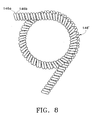
- FIG. 8 shows a double coil which is set into a closed configuration
- FIG. 9 is a tissue connector assembly, which may include the fastener of any of FIGS. 1 - 8 ;
- FIGS. 10A and 10B are sectional views of a fastener release mechanism, which may be used in the assembly of FIG. 9;
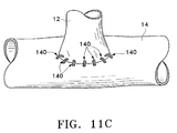
- FIGS. 11A, 11B and 11 C diagrammatically illustrate the placement of fasteners in an anastomosis
- FIG. 12 shows a double needle tissue connector assembly
- FIG. 13A shows a release mechanism that may be used with the second needle in the assembly of FIG. 12;
- FIGS. 13B and 13C show another release mechanism that may be used with the second needle in the assembly of FIG. 12, where FIG. 13C is a sectional view of FIG. 13B taken along line 13 C- 13 C;
- FIGS. 14A, B and C show another release mechanism that may be used with the second needle in the assembly of FIG. 12, where FIGS. 14A and 14B are partial sectional views of the system in a coupled and decoupled state, respectively, and FIG. 14C is a transverse cross-sectional view taken along line 14 C- 14 C in FIG. 14B;
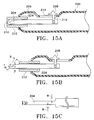
- FIGS. 15A, 15B and 15 C show fastener removal apparatus which may be used with the present invention where FIGS. 15A and 15B are sectional views and FIG. 15C is a top view of the elongated grabber member of FIGS. 15A and 15B;
- FIGS. 16A, 16B, 16 C and 16 D diagrammatically illustrate removal of a fastener with the apparatus of FIGS. 15 A-C;
- FIGS. 17A and 17B are sectional views of another embodiment of the fastener removal apparatus
- FIGS. 17C and 17D are sectional views of a variation of the cam mechanism of FIGS. 17A and 17B in combination with the hooked fastener grabber of FIGS. 15 A-C;
- FIGS. 18A and 18B are sectional views of another embodiment of a fastener removal apparatus that may be used with the present invention.
- FIGS. 19A, 19B and 19 C show another embodiment of a fastener removal apparatus that may be used with the present invention
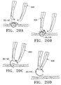
- FIGS. 20A, 20B, 20 C and 20 D diagrammatically illustrate removal of a fastener using the apparatus of FIGS. 19 A-C;
- FIG. 21 shows a variation on the apparatus of FIGS. 19 A-C.
- FIG. 22 shows another variation on the apparatus of FIGS. 19 A-C.
- Tissue connectors such as those discussed in PCT publication nos. WO 99/62406 and WO 99/62409, as described above are also disclosed in currently copending and commonly assigned application Ser. No. 09/090,305, filed Jun. 3, 1998, which is incorporated herein, by reference thereto, in its entirety.
- a fastener e.g., fastener 20
- a deformable wire 34 made of a shape memory alloy.
- a nickel titanium (e.g., Nitinol) based alloy may be used, for example.
- the Nitinol may include additional elements which affect the yield strength of the material or the temperature at which particular pseudoelastic or shape transformation characteristics occur.
- the transformation temperature may be defined as the temperature at which a shape memory alloy finishes transforming from martensite to austenite upon heating (i.e., A f temperature).
- the shape memory alloy preferably exhibits pseudoelastic (superelastic) behavior when deformed at a temperature slightly above its transformation temperature. At least a portion of the shape memory alloy is converted from its austenitic phase to its martensitic phase when the wire is in its deformed configuration. As the stress is removed, the material undergoes a martensitic to austenitic conversion and springs back to its original undeformed configuration.
- the shape memory alloy is preferably selected with a transformation temperature suitable for use with a stopped heart condition where cold cardioplegia has been injected for temporary paralysis of the heart tissue (e.g., temperatures as low as 8-10 degrees Celsius).
- shape memory alloy may also be heat activated, or a combination of heat activation and pseudoelastic properties may be used, as is well known by those skilled in the art.
- the cross-sectional diameter of the wire and length of the wire will vary depending on the specific application.
- the diameter “d” of wire 34 may be, for example, between 0.001 and 0.015 inch.
- the diameter is preferably between 0.001 and 0.008 inch with a diameter D 1 of the loop (FIG. 5) being between 0.0125 and 0.0875 inch.
- the wire 34 may have a circular cross-sectional shape and a generally spiral shaped configuration when in a closed position.
- the diameter D 1 of the loop of the fastener 20 , with coil 26 , in its closed position is preferably sized to prevent movement between adjacent tissues.
- wire 34 may have other cross-sectional shapes such as rectangular, or may be formed from multiple strands.
- One end of wire 34 may include an enlarged portion 36 having a cross-sectional area greater than the cross-sectional area of the wire and diameter of the coil to resist the coil from passing thereover.
- enlarged portion 36 may have a cross-section that allows the coil to be pulled over the enlarged portion.
- the cross sectional diameter of the enlarged portion may be about equal to the inside diameter of the coil.
- the enlarged portion 36 also may be provided to cooperate with a release mechanism, which is described in further detail with reference to the present invention below.
- the wire 34 is first formed in the generally spiral shaped configuration shown in FIG. 2.
- the wire 34 may be formed in the above described shape by first wrapping the wire onto a mandrel and heat treating the wire at approximately 400-550 degrees Celsius for approximately 5 to 30 minutes. The wire 34 is then air quenched at room temperature.
- the mandrel may have a constant diameter or may be conical in shape, to facilitate forming the spiral configuration shown in FIG. 5. Other shapes are possible as described in application Ser. No. 09/090,305.
- Coil 26 is formed by wrapping a wire around a cylindrical mandrel (not shown) thereby cold-working the wire into a coil shape having a straight axial configuration as shown in FIG. 3.
- the coil 26 is axially slid over the wire 34 whereupon it takes on the substantially spiral shaped configuration of the wire 34 .
- a locking device such as 28 a , for example (FIG. 4) is locked in position over enlarged portion 36 .
- an additional enlarged portion 38 is slid on the wire 34 and driven against the coil 26 to compress the same and open the fastener.
- the enlarged portion 38 is then fixed to the wire 34 by swedging or equivalent fixation technique.
- any extension of the wire 34 beyond enlarged portion 38 is removed or cut off from the fastener assembly 20 .
- the spring or coil 26 releases stored energy and expands to abut against the enlarged portion 36 again, which also allows the wire 34 to resume its substantially spiral shaped configuration, thereby also conforming the coil 26 into the substantially spiral-shaped configuration. Because the coil was not originally formed in the substantially spiral-shaped configuration, its tendency, if unaffected by outside forces, would be to return to the straight configuration, or possibly to remain in its present configuration, as in the case of a thin, malleable, platinum coil. Thus, the coil 26 , at best, does not aid the wire 34 in returning the fastener 20 to its closed position or free state, and, at worst, actually hinders the wire 34 from returning to the closed position. This further translates to possibly reducing the static closing force of the fastener somewhat.
- a fastener 140 is formed such that the coil 146 assists the wire 154 in its return to the closed state.
- the coil 146 forms an integral part of the fastener (i.e., fastening system) so as to assist in the closing thereof.
- the wire 154 may be first formed in the generally spiral shaped configuration shown in FIG. 2.
- the wire 154 is wound on a clip fixture, e.g. a tapered shaft (not shown), and is then heat treated, in a first heat cycle, in a convection oven set at a temperature ranging from about 450° C. to less than about 500° C.
- the wire is heated in a first heat cycle at a temperature of about 475° C. for about six minutes.
- the first heat cycle does not fully remove the cold worked stresses in the wire 154 , since the first heat cycle is performed below 500° C.
- the wire 154 may be formed in various other configurations, some examples of which are described in application serial Ser. No. 09/090,305, the entire contents of which are hereby incorporated by reference thereto.
- Enlarged portion 156 is formed prior to the first heat cycle of the wire 154 , and may be formed by attaching a member to the end of wire 154 by welding, gluing or other suitable attachment means or may be formed integrally with the wire by deforming the end of the wire, such as by heat (melting).
- Coil 146 is formed by first wrapping a wire of shape memory material, such as Nitinol around a cylindrical mandrel (not shown) and then heat setting the wire in a first heat cycle by placing it and the mandrel in a convection oven set at a temperature ranging from about 450° C. to less than about 500° C. for a period of about one to twenty minutes, to set it in an axially straight, configuration such as shown in FIG. 3A.
- the coil is heated in a first heat cycle at a temperature of about 475 ° C. for about six minutes.
- a pair of Nitinol wires (each preferably having about the same length and diameter as wire 146 ) 146 a , 146 b may be wound side-by-side around the cylindrical mandrel and then heat set in a first heat cycle by placing the pair and the mandrel in a convection oven and heat treating in a first heat cycle according to the parameters described above, to set it in an axially straight, double coil configuration 146 ′, such as shown in FIG. 3B.
- other materials which exhibit a sufficient shape memory ability could be substituted for Nitinol, as would be apparent to one of ordinary skill in the art.
- more than two adjacent wires (e.g., 3, 4 or more) may be wrapped and heat set in a similar procedure.
- the coil 146 ′ (or 146 , depending on whether a double or single coil (or more) is used) is axially slid over the wire clip 154 , such that the leading end of the coil 146 ′ abuts or lies adjacent to the enlarged portion 156 , whereupon it takes on the substantially spiral-shaped configuration of the wire 154 , as shown in FIG. 6.
- the assembly (wire 154 and coil 146 , 146 ′) is again heat treated in a second heat cycle, this time in a salt bath, to form an integrated system, wherein the shapes of both components are formed to one another so as to function in concert upon closing of the fastener.
- the salt bath may be sodium nitrate and potassium nitrate in a 50/50 mixture by weight percent for example. Alternatively, other molten mixtures could be used as would be apparent to those of ordinary skill in the art.
- the purpose of the salt bath is to provide a much more stable process, with more efficient and constant heat transfer to the entire assembly, thereby optimizing the strength of the fastener by removing any residual cold-worked stress in the materials to optimize the configuration of the fastener.
- the salt bath is heated to a temperature of about 500-530° C. and the fastener is submerged therein for a period of about one to six minutes.
- the fastener may be submerged in a salt bath having a temperature of about 515° C. for about two minutes.
- the shape of the coil 146 after treatment in the salt bath cycle is memory set into the shape of the clip 154 , as shown in FIG. 1A, for example, so that each component has a substantially spiral-shaped memory set.
- other shapes of the wire 154 could be made initially, as noted above, after which the coil 146 would be processed in the same way as described above, to take on a memory set provided by the shape of the wire 154 .
- the fastener is assembled with a locking mechanism, much in the same manner as described above with regard to previous embodiments.
- enlarged portions have been described with spherical and cylindrical configurations, other configurations or configuration combinations can be used.
- both enlarged portions may be spherical or both may be cylindrical, etc.
- a locking mechanism such as 28 a for example, is locked in position over the enlarged portion 156 .
- an additional enlarged portion 158 is slid on the wire 154 and driven against the coil 146 , 146 ′ to compress the same and open the fastener (FIG. 7).
- enlarged portion 158 is then fixed to the wire 154 by swedging or equivalent fixation technique.
- any extension of the wire 154 beyond enlarged portion 158 is removed or cut off from the fastener assembly 140 .
- enlarged portions 156 and 158 are shown with spherical and cylindrical configurations, other configurations or configuration combinations can be used.
- both enlarged portions may be spherical or cylindrical, or portion 156 may be cylindrical and portion 158 spherical.
- a coil (not shown) having sufficient stiffness, for example, may be used where adjacent loops do not contact one another when the coil is compressed to force wire 154 into an open position.
- the end of the spring 146 adjacent the enlarged portion 158 is held in a fixed position relative to the wire 154 .
- the opposite end of the spring 146 is free to move along the wire 154 and is held in place when the spring is in its compressed position by a locking device or release mechanism 28 a.
- fastener 140 is shown in closed and open configurations.
- the fastener When wire 154 is in an undeformed or closed configuration, the fastener is closed (FIG. 1) for keeping or connecting tissue together.
- the fastener When wire 154 is in a deformed or open configuration, the fastener is open (FIG. 7) for insertion of the wire into tissue.
- wire 154 is in its closed configuration when in a relaxed state, and likewise, coil 146 is in a closed configuration when in a relaxed state. Wire 154 and coil 146 are preferably not deformed past their yield points in the open position.
- fastener 140 may have a U-shaped configuration in its open position to facilitate insertion of the wire through the tissue.
- other configurations may be used including, but not limited to C-shaped, V-shaped, J-shaped, and other similarly shaped configurations.
- the helical wire 154 may have other cross-sectional shapes and be formed of different materials which exhibit shape memory characteristics.
- Coil 146 is preferably sized so that when in its free (uncompressed state) it extends the length of wire 154 with one end adjacent to enlarged portion 156 and the other end adjacent to enlarged portion 158 . It is to be understood that the coil may not extend the full length of the wire.
- a flange or similar device may be provided on an intermediate portion of wire 154 to limit movement of the coil along the length of the wire.
- a fastener according to the present invention can be formed in still other configurations.
- One or both ends of the fastener may extend in a substantially straight direction from the curved form of the wire 154 .
- the straight sections of extensions may extend for a length equal to about two to three times the outside diameter of the coil 146 (as compared to the diameter of the loop) or about 0.010 to 0.020 inches. These extensions may allow the release mechanisms (discussed in detail below) to operate more efficiently and also may simplify manufacture of the fastener.
- the fastener may be embodied by a wire (a small clip), having a cross-sectional thickness of about 0.0035 inches, which, similar to the closed configuration of the prior art fastener shown in FIG. 5, forms an inner loop having a diameter D 1 of about 0.017 inches and an outer loop dimension D 2 (horizontally measured from inside of the loop) of about 0.021 inches.
- the exemplary clip may form a U-shape with a depth of the U-shape being about 0.032 inch (0.8 mm).
- a fastener 140 ′ with two extensions and a stopper 142 is shown.
- the stopper preferably is slidably mounted onto the wire 154 in the vicinity of the transition from a curved wire portion, to the relatively straight extension.
- the stopper is placed between discrete springs 146 ′′ and 146 ′′′ and held in place thereby.
- Either or both of springs 146 ′′ and 146 ′′′ may be single or double coils (or more) as described above and may be set according to the procedures described with regard to coils 146 and 146 ′.
- FIGS. 1B and 1C are particularly advantageous for anastamosing a relatively thin-walled vessel to a relatively thick-walled vessel (e.g., the aorta or other large vessel), where an extension acts to prevent the relatively thin-walled vessel from sliding into the anastomosis site and out of the preferred position where it is to be fixed, as is illustrated in FIG. 1C.
- a relatively thick-walled vessel e.g., the aorta or other large vessel
- this fastener design may be embodied by a wire (wire 154 ) having a cross-sectional thickness of about 0.0045 inches, which, in the closed configuration shown forms an inner loop having a diameter D 1 of about 0.060 inches and an outer loop dimension D 2 of about 0.065 inches. In the open configuration, the fastener forms a U-shape with a depth of the U-shape being about 0.07-0.09 inch (1.5 to 2 mm).
- fasteners may have undeformed or deformed configurations different than those shown herein without departing from the scope of the invention.
- a locking clip (not shown) may also be attached to connect the ends of the fastener when the fastener is in its closed position to prevent possible opening of the fastener over time.
- the locking clip may also be integrally formed with one end of the fastener.
- the tissue connector assembly 10 generally comprises a tissue piercing or penetrating member 16 , a flexible member 18 , and a fastener or surgical clip 140 .
- a restraining device, generally indicated at 24 and comprising a spring (or coil) 146 and a locking device (or release mechanism or coupling member) generally indicated at 28 is connected to the fastener 140 for holding the fastener in a deformed configuration as further described below.
- Piercing or penetrating member 16 which may be in the form of a needle (such as a 7-0 or 8-0 needle), has a sharp pointed tip 30 at its distal end for penetrating tissue.
- Member 16 may be bent as shown in FIG. 9, for example.
- the diameter of at least a portion of member or needle 16 is preferably greater than the diameter of flexible member 18 so that the flexible member can easily be pulled through an opening formed in the tissue by the needle.
- the distal end of member or needle 16 is preferably rigid to facilitate penetration of tissue.
- the remaining length of member or needle 16 may be rigid or flexible to facilitate movement of the needle through the tissue as further described below.
- the tip 30 of member or needle 16 may have various configurations and may, for example, be conical, tapered, or grounded to attain a three or four facet tip.
- Member or needle 16 may be made from stainless steel or any other suitable material, such as a polymeric material. It is to be understood that member or needle 16 may have a shape or radius of curvature other than the one shown, without departing from the scope of the invention. Member or needle 16 may also be integrally formed with the flexible member 18 (e.g., both needle and flexible member formed of the same material.)
- Flexible member 18 may be in the form of a suture formed from conventional filament material, metal alloy such as Nitinol, polymeric material, or any other suitable material.
- the material may be non-stretchable or stretchable, solid or hollow, and have various cross-sectional diameters.
- the flexible member or suture may have a cross-sectional diameter of 0.003 inch, for example. The diameter and length of the suture will vary depending on the specific application.
- the suture may be attached to the needle 16 by crimping or swaging the piercing member or needle onto the suture, gluing the suture to the piercing member or needle, or any other suitable attachment method.
- Flexible member 18 may have cross-sectional shapes other than the one shown herein and may have other constructions as well.
- Locking device or release mechanism 28 a comprises a plurality of substantially rigid strands, preferably wires 106 , arranged substantially parallel to one another and circularly about a longitudinal axis of the aligned strands, to form a tube-like configuration, as can be seen in the cross-sectional view of FIG. 10B.
- strands 106 may be cables or some other substantially rigid strand elements arranged in the same manner as the wires shown in FIG. 10B.
- the hidden end portions 106 a of the strands are coupled to tapered section 2 , which is coupled to a piercing member or needle through a flexible member such as flexible member 18 .
- a rod 162 extends from tapered section 2 to facilitate fixation of the strands thereto.
- the coupling of the strands to tapered section 2 is preferably accomplished by gluing or soldering to rod 162 , although other equivalent or similar known joining techniques may be employed (e.g., welding, threadably attaching, etc).
- rod 162 is preferably glued, soldered or threaded into the needle or transition element.
- the flexible member may extend through tapered section 2 and form a substitute structure for rod 162 . This may be preferred when the flexible member is a metal wire.
- the end portions 106 b of the strands in the vicinity of the fastener strands include notches 109 which are formed into the strands to a depth equal to approximately half the diameter of the strand 106 .
- the notches 109 form a chamber 108 configured for receiving and holding enlarged portion 156 .
- enlarged portion 156 is shown as having a spherical shape, it may have other shapes including a barrel shape, or other shape that may be easily grasped and easily released.
- the notches are preferably placed about 0.015′′ from the free ends of the strands, but this distance, of course, can be modified, depending upon the amount of compression of spring 146 that is desired when ball 156 is inserted into the chamber 108 and held by notches 109 .
- a shrink wrap layer preferably a shrink tubing 110 may be provided over at least free end portions 106 b of wires or strands 106 , and the tubing heated to compress against strands 106 and hold them in place against ball 156 , preferably symmetrically against ball 156 .
- tubing 110 and strands 106 effectively hold ball 156 captive within notches 109 .
- other plastic or elastic restraining members may be mounted around the distal portions of the wires or strands to aid in maintaining them in place, preferably symmetrically against ball 156 .
- strand members may be designed with an elastic spring force sufficient to maintain notches 109 in place with sufficient force to maintain the ball 156 captive therein under the tensile forces normally experienced during a suturing procedure.
- the number of strands may vary depending on, for example, the size of the clip or the size of the strands. Typically, the number of strands may range from two to ten. In a coronary anastomosis, the number of strands preferably will range from five to seven although other numbers may be used.
- enlarged portion 156 of wire 154 is placed in chamber 108 .
- Tubing 110 is wrapped around at least a portion of the strands (as shown in the drawings) and heated to maintain enlarged portion 156 captive within the cavity formed by the strands.
- Compression coil or spring 146 is slid over wire 154 and enlarged portion 158 is slid over the wire 154 and slid against spring 146 to compress the coil against portions 106 b such that the fastener is in its open configuration.
- Enlarged portion 158 may then be swedged or otherwise fixed to wire 154 to maintain the fastener in its open configuration.
- Release mechanism 28 a is movable between a locked position and an unlocked position.
- the ball 156 In the locked position the ball 156 is held within notches 109 and consequently, coil 146 is held in its compressed position, thereby maintaining fastener wire 154 in its deformed or open position.
- the unlocked position ball 156 is released from the notches, thereby allowing the coil 146 to expand, and releasing the closing forces produced by both the wire 154 and the coil 146 , causing the fastener 140 to close.
- the coil 146 remains integral with the wire 154 upon closing of the fastener 140 .
- the closing actions or forces provided by the wire 154 and coil 146 act in concert to provide an optimal closing force of the fastener upon the tissues, tissue and graft, etc.
- the coil 146 remains integral with the wire or clip 154 after closing of the fastener 140 , and both components cooperate to maintain the anastomosis.
- Movement of the release mechanism to the open position is accomplished by applying a compressive force to the shrink tube 110 and bundle of strands 106 .
- the compressive force may be applied at any opposing locations around the circumference of the shrink tube as long as the implement applying the force is oriented at an angle to the strands, preferably substantially perpendicular thereto, to allow the implement to traverse the strands so as to deform the positions thereof when the force is applied.
- the strands or wires 106 get distorted from their circular configuration under the compression.
- This change in shape stretches the shrink tube 110 from a circular configuration to a somewhat elliptical configuration, and removes some of the notches 109 from contact with ball 156 , thereby permitting removal of ball 156 from within the chamber previously formed by notches 109 in the closed position.
- the tissue connector assembly 10 has many uses. It may be especially useful for minimally invasive surgical procedures including creating an anastomosis between a vascular graft 12 and an artery 14 (FIGS. 11 A- 11 C). The anastomosis may be used to replace or bypass a diseased, occluded or injured artery.
- a coronary bypass graft procedure requires that a source of arterial blood flow be prepared for subsequent bypass connection to a diseased artery.
- An arterial graft may be used to provide a source of blood flow, or a free graft may be used and connected at the proximal end to a source of blood flow.
- the source of blood flow is one of any number of existing arteries which may be dissected in preparation for the bypass graft procedure.
- LIMA left internal mammary artery
- RIMA right internal mammary artery
- Other vessels which may be used include the saphenous vein, gastroepiploic artery in the abdomen, radial artery, and other arteries harvested from the patient's body as well as synthetic graft materials, such as DACRON® (polyester fibers) or GORETEX® (expanded polytetrafluoroethylene).
- the upstream end of the dissected vessel which is the arterial blood source, will be secured to the aorta to provide the desired bypass blood flow, as is well known by those skilled in the art.
- the downstream end of the graft vessel is trimmed for attachment to an artery, such as the left anterior descending coronary (LAD). It is to be understood that the anastomosis may be formed in other vessels or tissue.
- LAD left anterior descending coronary
- the patient is first prepped for standard cardiac surgery. After exposure and control of the artery 14 , occlusion and reperfusion may be performed as required. An arteriotomy is performed on artery 14 to provide an opening 120 for receiving a graft vessel (FIG. 11A). After the snared graft vessel 12 has been prepared and made to the appropriate length as would be conventional in the art, a tissue connector assembly 10 is attached to the free end of the graft vessel along an edge margin of the vessel.
- the surgeon grasps the needle 16 with a needle holder (e.g., surgical pliers, forceps, or any other suitable instrument) and inserts the needle 16 into the tissue of the graft vessel 12 in a direction from the exterior of the vessel to the interior of the vessel.
- the surgeon then releases the needle 16 and grasps a forward end of the needle which is now located inside the graft vessel 12 and pulls the needle and a portion of the suture 18 through the vessel.
- the needle 16 is passed through opening 120 formed in the sidewall of the artery 14 and inserted into the tissue of the artery in a direction from the interior of the artery to the exterior of the artery.
- a second tissue connector assembly 10 may be inserted at a location generally 180 degrees from the location of the first tissue connector in a conventional “heel and toe” arrangement.
- the graft vessel 12 is positioned above and aligned with the opening 120 in the sidewall of the artery 14 (FIG. 11A).
- a section of each suture 18 is located between the graft vessel 12 and artery 14 .
- the fasteners 140 and needles 16 are pulled generally away from the artery 14 to reduce the length of the suture 18 (eliminate slack of the suture) between the vessel 12 and artery and “parachute” the vessel onto the artery (FIG. 11B).
- the needles 16 are then pulled away from the artery 14 until each fastener 140 is positioned within the graft vessel 12 and artery with one end of each fastener 140 extending from the vessel and the opposite end of each fastener extending from the artery.
- a surgical instrument e.g., needle holder
- each locking device 28 is used to radially squeeze to release the locking device from the fastener 140 .
- the coil 146 moves to its free uncompressed state which allows both the wire 154 and coil 146 to return to their memory configurations which define the closed position (FIG. 11C).
- the wires 140 move to their closed positions the adjacent tissues of the graft vessel 12 and artery 14 which were previously pulled together during the parachuting of the graft vessel onto the artery, are squeezed together to securely engage the graft vessel and artery.
- the graft and arteriotomy edges may be abutted or everted as is known in the art.
- the locking device 28 provides for simultaneous actuating closure of the fastener 140 and release of the needle 16 from the fastener.
- tissue connector assemblies 10 are used to make connections at generally opposite sides of the graft vessel. Additional tissue connector assemblies 10 may be used to make connections between those.
- the procedure may be accomplished with a beating heart procedure with the use of a heart stabilizer to keep the heart stable, for example. The procedure may also be performed endoscopically.
- tissue connector assemblies 10 may be inserted generally around the location of the heel.
- the graft vessel may then be pulled towards the artery to determine whether the opening formed in the sidewall of the artery is large enough before completing the anastomosis.
- double needle assemblies 11 (FIG. 12 described below) are used. Each needle of a double needle assembly 11 is passed from inside to outside of the respective graft and artery. The first assembly is placed at the “heel” (6 O'clock) position, the tissue brought together in the clip and the clip closed.
- Another double needle assembly is then placed a the 5 O'clock position and closed, 7 O'clock position and closed, 12 O'clock position and closed, 1 O'clock position and closed, 11 O'clock position and closed.
- Three single needle assemblies 10 are then evenly spaced between the 6 and 12 O'clock positions (placed laterally) and the tissue placed therein. These fasteners are then closed.
- Three more single needle assemblies 10 are placed on the other lateral side of the anastomosis in the same manner as the first lateral fasteners.
- the multiple piercing member construction facilitates threading ends of the assembly from inner to outer wall(s) of material, such as tissue, which may eliminate or minimize the possibility of dislodging material, such as plaque, from the inner wall of calcified arteries, for example, as will become more apparent from the description provided below.
- two piercing members each of which may comprise a needle, are releasably coupled to a fastener.
- the coupling between the flexible member (and, thus, the piercing member) and the fastener may be constructed to actuate closure of the fastener upon release of the flexible member (or piercing member).
- the coupling may hold a compression spring (which is positioned around a fastener) in a compressed state to brace the fastener open and releasably lock or secure the fastener to the flexible member (or piercing member).
- a tissue connector assembly 11 which generally comprises tissue piercing or penetrating members 16 and 17 , flexible members 18 and 19 , and a fastener 140 (e.g., a surgical clip) is shown.
- a restraining device, generally indicated at 24 and comprising a spring (or coil) 26 and a locking device (or coupling member) generally indicated at 28 is connected to fastener 140 for holding the fastener in a deformed or open configuration as described previously. That is, the spring or coil is adapted to be integrated with the wire or clip, to act in concert therewith, for closing the fastener with and optimal closing force and action.
- Penetrating or piercing member 17 may be made in accordance with the description provided above in connection with penetrating member 16 , and, thus may, for example, be in the form of a needle (such as a 7-0 or 8-0 needle) having a sharp pointed tip 31 at its distal end for penetrating tissue.
- Members 16 and 17 may be the same or differ from one another.
- Flexible members 18 and 19 also may have the same construction.
- release mechanism 28 a also may be used to releasably couple the other end of the fastener to another flexible member such as flexible member 19 , which in turn, is coupled to a needle such as needle 17 as shown in FIG. 12.
- a member or stopper 115 which may be annular, is secured to the other end of the fastener or wire 154 to prevent enlarged portion 156 or 158 (since wire 154 may have substantially symmetrical ends when employing double penetrating members) from passing through the compression spring upon release from release mechanism 28 a.
- FIGS. 13B and 13C illustrate a synchronized fastener release system.
- One release mechanism may correspond to mechanism 28 a .
- a release mechanism which responds to the compressive state of coil 146 and releases the fastener or wire 154 upon release of compressive forces on the coil is shown and generally designated with reference numeral 29 a .
- release mechanism 29 a comprises two members 121 each having a recess 122 formed therein and arranged to form chamber 124 when members 121 are aligned as shown in FIG. 13B.
- Recesses 122 are configured to retain enlarged portion 156 or 158 , which is shown with a cylindrical configuration, but may have a spherical or other suitable shape for operatively associating with a suitably configured chamber. Further, members 121 may have semicircular transverse cross sections or some other combination of transverse shapes that can collectively provide the desired chamber to retain enlarged portion 156 or 158 . The number of members 121 also may vary as would be apparent to one of ordinary skill.
- Release mechanism members 121 have tapered ends 126 , which are configured for positioning between coil 146 and fastener wire 154 as shown in FIG. 13B. When tapered ends 126 are so positioned and coil 146 is in a compressed state, coil 146 holds tapered ends 126 , which are normally biased away from each other, sufficiently together to retain enlarged portion 156 or 158 within chamber 124 .
- release mechanism 28 a When release mechanism 28 a is actuated (e.g., radially compressed) to release enlarged portion 156 or 158 of fastener wire 154 , coil 146 assumes its relaxed state, thereby releasing tapered ends 126 of release mechanism 29 a from the coil and allowing the tapered ends to radially expand and release enlarged portion 156 or 158 of fastener wire 154 . Accordingly, both needles and flexible members may be decoupled from the fastener when release mechanism 28 a is actuated.
- FIGS. 14 A- 14 C show another synchronized fastener system which is similar to the system shown in FIGS. 13 A- 13 C.
- Release mechanism 28 c may be of the type described above with regard to reference numeral 28 a or may be a variety of other mechanisms including those described in copending, commonly assigned application Ser. Nos. 09/090,305, filed Jun. 3, 1998; 09/089,884, filed Jun. 3, 1998; 09/259,705, filed Mar. 1, 1999; and 09/260,623, filed Mar. 1, 1999; all of which are incorporated herein by reference thereto, in their entireties.
- Release mechanism 29 b and the cooperating portion of the fastener or wire 154 are also varied from release mechanism 29 a .
- an annular member or stopper 115 which may be annular, is slidably coupled to fastener wire 154 .
- Member 115 is configured to resist passage of coil 146 thereover. Accordingly, member 115 may have an outer diameter slightly greater than at least the portion of the coil adjacent thereto.
- a tapered or frustoconical member 3 ′ is secured to an end of fastener wire 154 , which need not include an enlarged portion.
- Member 3 ′ is the same as member 3 with the exception that member 3 ′ has a channel 134 for receiving flexible member or suture 19 . Channel 134 extends radially outward from bore 132 , which is formed through member 3 ′, for receiving the fastener or wire 154 (FIG. 14C).
- Flexible member 19 is threaded through channel 134 and between tapered member 3 ′ and annular member 115 .
- coil 146 When coil 146 is in a compressed state as shown in FIG. 14A, the coil urges member 115 toward tapered member 3 ′ and compresses flexible member 19 therebetween. In this manner, flexible member 19 is secured to the fastener or wire 154 .
- release mechanism 28 c When release mechanism 28 c is actuated (e.g., radially compressed) to release enlarged portion 156 of the fastener or wire 154 , coil 146 assumes its relaxed state so that annular member 115 may slide away from tapered member 3 ′ and release flexible member 19 . Accordingly, both needles and flexible members may be removed from the fastener when release mechanism 28 c is actuated.
- a metal flexible member may be used, a polymeric flexible member may be preferred.
- the fastener may not leave much to grab onto for its removal if desired. In addition, there may be no free ends to grab, which may make it difficult to remove without damaging the tissue around which it is wrapped.
- removal apparatus and methods according to the present invention.
- the apparatus generally comprises a grabber member 204 having a hook 210 and slidably mounted within sleeve 212 .
- Sleeve 212 may have a blunt distal end so that it may restrain tissue movement as the fastener is drawn therefrom.
- Sleeve 212 may be mounted within housing 206 , which includes a slot 214 through which flange 216 of sliding button 208 is disposed.
- One end of the flange 26 is secured to the grabber member so that the grabber member can be withdrawn and extended from the sleeve as shown in FIGS. 15A and 15B.
- the hook may be formed at an angle of about 50-70 degrees ( ⁇ ) and has a width (“z”) and depth (“y”) slightly larger than the diameter of wire 154 and coil 146 (or 146 ′, 146 ′′, 146 ′′′) (e.g., about 0.001 inch greater than the diameter of the wire and coil). “z” and “y” thus may be essentially the same and may be in the range of about 0.005-0.020 inch. This configuration has been found to enhance the grabber member's ability to grab the fastener and pull it out of the tissue or material in which it is placed.
- FIGS. 16 A- 16 D fastener removal is diagrammatically shown.
- the fastener wire is placed in the slot of the hook, it is pulled inside the tubular sleeve 212 .
- the fastener enters the sleeve, it is bent in half and the coils surrounding the clip wire are compressed down towards the ends of the clip.
- This bending of the clip wire, combined with the compression of the coil causes the clip to open up enough to be pulled out of the tissue without damaging it and up into the tube or sleeve 212 .
- FIG. 15C which is a top view of the grabber member, a portion of the grabber member adjacent the hook, has a reduced thickness to provide sufficient space for the fastener to be drawn within the sleeve, while straightening the wire and coil as it is pulled therein.
- the space “s” on each side of the member generally corresponds to the diameter of the wire and coil and may range, for example, from about 0.004 to 0.010 inch.
- the hooked grabbing member can be retracted into the tube as described above.
- the sleeve 212 can be slidably mounted in housing 206 and attached to flange 216 of button 208 , with the hooked grabbing member being fixed to the housing 206 .
- a hooked grabbing mechanism is shown, it should be understood that other grabbing mechanisms can be used. Examples of other mechanisms include, but are not limited to, alligator-type jaws or a lasso-like wire loop as shown in FIGS. 17 A-B and 18 A-B, respectively.
- the jaw portion has a reduced width to allow entry of the fastener as in the hooked grabber as shown in FIG. 15C.
- the sleeve lumen is sufficiently small to generally straighten the fastener 140 .
- FIGS. 17A and 17B Another grabber displacement mechanism also is shown in FIGS. 17A and 17B for use with the present invention.
- a cam system is used to actuate movement of the grabber member.
- the cam system can be arranged to reciprocate the sleeve instead of the grabber member.
- One or more buttons 208 ′ are pivotally mounted to housing 206 to engage cam member 218 , which may be in the form of a frustoconical member surrounding a portion of the grabber member, such as jaws type grabber member 220 .
- a restraint such as coil spring 222 is placed between the cam member and housing annular flange 224 to bias the grabber into the sleeve as shown in FIG. 17A.
- the buttons 208 ′ are squeezed, the buttons engage camming surfaces 226 and force the grabber member out from sleeve 212 as shown in FIG. 17B.
- FIGS. 17 C-D Further cam actuated grabber displacement mechanisms are shown in FIGS. 17 C-D. These cam systems also are used to actuate movement of the grabber member.
- Actuator or cam member 208 ′′ is pivotally mounted to housing 206 at pin “p′”.
- the actuator comprises a lever arm and camming projection or interface 209 which extends from the lever arm to engage camming surface 226 ′ of cam follower member 218 ′.
- Cam follower 218 ′ preferably is secured to one end of the grabber member, which may be hook grabber member 204 .
- a restraint, such as coil spring 223 is placed between the cam follower and sleeve 212 to bias the grabber into the sleeve as shown in FIG. 17C.
- cam projection 209 moves along camming surface 226 ′ and imparts translational motion to the cam follower, which in turn, forces the grabber member out from sleeve 212 as shown in FIG. 17D.
- any of the cam systems shown in FIGS. 17 A-D can be arranged to reciprocate the sleeve instead of the grabber member.
- buttons 208 ′′′ extending from the housing and pivotally movable relative thereto.
- a circumferential groove 228 can be formed in the housing at the juncture where the flaps extend to enhance the pivoting capability of the flaps.
- the piston is biased against such axial movement through coil spring 222 , which is mounted between the piston and annular flange 224 of the housing.
- the piston is secured to the elongated grabber member 232 (which has loop 234 extend therefrom) so that the grabber member travels or reciprocates with the piston.
- the number of buttons may vary. For example, a single button actuator design can be used. It also should be understood that any of the actuating mechanisms and grabber mechanisms described above may be combined.
- FIGS. 19 A- 19 B one embodiment is shown comprising a generally a two-part design that when assembled, resembles a pair of surgical tweezers or forceps.
- This embodiment is generally designated with reference numeral 300 .
- the distal tip of each leg tapers down to less than about 0.010 inch thickness (“t”, see FIG. 19C) at which point there is approximately a 90 degree bend inward, toward the other leg of the tweezers.
- This bent portion extends inward some distance (which may be about 0.1 inch) and may be about 0.035′′ in height.
- a slot cut through this bent-in portion that is the shape of a “V” or a “tapered U” and generally designated with reference numeral 302 .
- the deepest part of the slot S d is equal to or slightly larger than the diameter of the fastener wire 154 .
- the other end of the slot is greater than the combined diameter of the wire 154 and coil 146 ( 146 ′, 146 ′′, 146 ′′′) of the fastener.
- the beveled portions wedge between coil turns and compresses the coil.
- the beveled portions each comprise a chamfer which extends all around slot 302 . This forms something resembling a two-tined fork.
- This thin profile member is completely flat, while the other side is chamfered around the “V” profile (See FIG. 19C where 13 is about 55-65 degrees and may vary depending on the amount of taper to reach dimension “t”).
- the bevel is generally designated with numeral 304 (FIG. 19B).
- the flat sides of the member on each leg face each other, while the chamfered surfaces face outward away from each other.
- FIGS. 20 A- 20 D an example of fastener removal is shown.
- the surgeon simply brings one of the protruding members (forked parts) in at a right angle to the clip, and catches a portion of the clip in the “V” profile (between the tines of the fork).
- the tweezers legs are squeezed together.
- the clip becomes engaged in the “V” groove of the second member. At this point the clip is resisting (trapped) between the bottoms of the two “V” grooves.
- FIGS. 21 and 22 Other tip configurations also can be used with this tweezers-style removal tool such as the variations shown in FIGS. 21 and 22.
- one leg of the tweezers can have a double edge head at the end of it (FIG. 21).
- FIG. 21 there are two protruding members, side-by-side at the tip. These two protruding members have enough space between them to allow the opposing protruding member on the other leg to slide between them.
- This configuration provides a more desirable bend in the clip, thus allowing easier removal.
- the beveled ends are turned about 90 degrees as compared to those in FIG. 19A.
- Apparatus 200 with the “Hook and Slide” design, lends itself to standard conventional manufacturing techniques.
- the hook itself can be made from drawn wire (stainless steel or Nitinol) which has been machined at the tip to form the hook. Wire EDM or laser cutting could also be used to form this hook at the end of the wire.
- the handle and finger slider (or squeeze buttons) are best injection molded from any number of plastic resins, most likely ABS. The handle halves could then be easily sonic welded together. It is conceivable that these parts could be machined from metal or some other material, although this would be a much costlier option.
- the outer tube which slides over the hook can be extruded or drawn metal or plastic.
- the “Shearing Tweezers” design has only two parts, both of which are machined form stainless steel or titanium blanks. The two machined pieces are welded together up near the top of the handle area.
- the instrument apparatus 200 is held by the surgeon in similar fashion to a pencil or surgical instrument, such as forceps or a probe.
- the hook is guided down to the clip and hooked around any part of the clip, preferably at a right angle to the clip.
- the hook is retracted into the outer tube of the device using the finger slider or squeeze buttons. If it is the wire loop or lasso, the loop must go over one of the free ends of the clip.
- the loop is then slid up onto the main part of the clip and then retracted (with the clip) into the outer tube using the finger slider or squeeze buttons. At this point the clip is out of the tissue and completely contained within the outer tube. It can be retrieved by reversing the action of the finger slider or squeeze buttons to push it out of the tube.
- the “Shearing Tweezers” are also simple to operate.
- the shearing tweezers are held just as any other surgical tweezers or forceps would be held.
- the surgeon guides the distal tip with the protruding member down to the clip and again, preferably at a right angle, slides the protruding member onto the clip. This is done so that the clip is resting in the bottom of the “V” groove, with one tine of the fork under the clip (between clip and tissue) and the other tine over the clip. Once in this position, the legs of the tweezers are squeezed closed. It sometimes requires multiple squeezes to be able to fully extract the clip.
Abstract
Description
- The present invention relates to surgical fasteners for connecting body tissues, tissue and prostheses, tissue and graft or any combination thereof.
- Minimally invasive surgery has allowed physicians to carry out many surgical procedures with less pain and disability than conventional, open surgery. In performing minimally invasive surgery, the surgeon makes a number of small incisions through the body wall to obtain access to the tissues requiring treatment. Typically, a trocar is delivered into the body with a cannula. After the trocar pierces into the body cavity, it is removed and the cannula is left with one end in the body cavity.
- When a minimally invasive procedure is done in the abdominal cavity, the retroperitoneal space, or chest, the space in which the operation is performed is more limited, and the exposure to the involved organs is more restricted, than with open surgery. Moreover, in a minimally invasive procedure, the instruments used to assist with the operation are passed into the surgical field through cannulae. When manipulating instruments through cannulae, it is extremely difficult to position tissues in their proper alignment with respect to each other, pass a needle through the tissues, form a knot with the suture material once the tissues are aligned, and prevent the suture material from becoming tangled.
- The fastening of body tissues together, or of fastening body tissues to graft materials becomes much more difficult in the restricted spaces imposed upon a surgeon when working through cannulae. Because the use of sutures is often difficult if not impossible in these situations, various other forms of fasteners have been developed to simplify the joining together of tissues and tissues with grafts in these environments, as well as in more conventional surgical procedures.
- One variation of a suture is disclosed in U.S. Pat. No. 5,002,563, which forms surgical sutures from shape memory alloys. A suture is formed in the shape of a loop and a needle is affixed to an end thereof. A straight sleeve is provided to maintain the suture relatively straight as it is being inserted into the tissues to be joined. Removal of the sleeve allows the suture to return to its memorized loop shape. End segments of the loop can then be interlocked manually to secure the wound closure. Although this device is less cumbersome than tying conventional sutures, it still requires a coordinated effort to advance the suture into the tissues while removing the sleeve during the insertion process. Also, the interlocking step is similar to suturing, if not as difficult or complicated as tying a conventional suture. This device is disclosed for use in closure of deep wounds and there is no suggestion of use in close environments such as in minimally invasive surgical procedures.
- PCT publication nos. WO 99/62406 and WO 99/62409, which are commonly assigned to the assignee of the present application, disclose tissue connector assemblies having a clip movable between an open state and a closed state and a mechanical restraining device attached to the clip for restraining the clip in its open state. The clip has a generally U-shaped configuration when in its open state. A needle may be releasably attached to the clip. This type of tissue connector assembly is discussed further below, with regard to FIGS. 4 and 5. PCT publication nos. WO 99/62406 and WO 99/62409 are incorporated herein, by reference thereto, in their entireties.
- The present invention involves surgical fasteners having biasing members which aid in the closure of the fasteners, and methods of making such fasteners. A fastener, according to the present invention, includes a clip movable between an open configuration and a closed configuration, and a biasing member contacting the clip and biased to conform to the closed configuration when in a free state. The biasing member may be applied to form an integrated system with the clip, such that the biasing member and clip actuate in concert to close the fastener, thereby providing an optimal fastener configuration exhibiting an optimal closing force.
- Additionally, the clip is biased to conform to the closed configuration when in a free state. The clip may comprise a wire having a shape memory which defines a closed configuration, which may be substantially spiral-shaped, or another shape.
- The biasing member may comprise a coil surrounding at least a portion of the clip, and may be a double coil. The biasing member may reside between two restraints located on the clip. Further, a release mechanism may be provided which is adapted to engage the clip at at least one of the restraints and to bias the biasing member to force the clip into the open configuration.
- A method of making a surgical fastener according to the present invention includes winding a clip, formed of a shape memory material, into a predetermined closed configuration; setting the clip into the predetermined closed configuration so that the clip has a memory configuration which is the predetermined closed configuration; and conforming a biasing member to the clip in the predetermined closed configuration; setting the clip and biasing member into the predetermined closed configuration to form a fastener comprising the clip and the biasing member wherein each has a memory configuration which is the predetermined closed configuration.
- The clip and biasing member may each be set by heating at a predetermined temperature for a predetermined time, and the combination of these components may further be set by heating at a predetermined temperature for a predetermined time.
- FIG. 1A is a view of a surgical fastener according to the present invention;
- FIGS. 1B and 1C show a variation of the fastener of FIG. 1A;
- FIG. 2 is a view of a clip, absent of any biasing member, in a closed configuration;
- FIG. 3A shows a single coil set in an axially straight configuration;
- FIG. 3B shows a double coil set in an axially straight configuration;
- FIG. 4 shows a prior art fastener in an open configuration;
- FIG. 5 shows the fastener of FIG. 4 in a closed configuration;
- FIG. 6 shows the positioning of a coil over a clip for setting the closed configuration of a fastener;
- FIG. 7 shows a fastener according to the present invention in an open configuration;
- FIG. 8 shows a double coil which is set into a closed configuration;
- FIG. 9 is a tissue connector assembly, which may include the fastener of any of FIGS. 1-8;
- FIGS. 10A and 10B are sectional views of a fastener release mechanism, which may be used in the assembly of FIG. 9;
- FIGS. 11A, 11B and 11C diagrammatically illustrate the placement of fasteners in an anastomosis;
- FIG. 12 shows a double needle tissue connector assembly;
- FIG. 13A shows a release mechanism that may be used with the second needle in the assembly of FIG. 12;
- FIGS. 13B and 13C show another release mechanism that may be used with the second needle in the assembly of FIG. 12, where FIG. 13C is a sectional view of FIG. 13B taken along
line 13C-13C; - FIGS. 14A, B and C show another release mechanism that may be used with the second needle in the assembly of FIG. 12, where FIGS. 14A and 14B are partial sectional views of the system in a coupled and decoupled state, respectively, and FIG. 14C is a transverse cross-sectional view taken along
line 14C-14C in FIG. 14B; - FIGS. 15A, 15B and 15C show fastener removal apparatus which may be used with the present invention where FIGS. 15A and 15B are sectional views and FIG. 15C is a top view of the elongated grabber member of FIGS. 15A and 15B;
- FIGS. 16A, 16B, 16C and 16D diagrammatically illustrate removal of a fastener with the apparatus of FIGS. 15A-C;
- FIGS. 17A and 17B are sectional views of another embodiment of the fastener removal apparatus;
- FIGS. 17C and 17D are sectional views of a variation of the cam mechanism of FIGS. 17A and 17B in combination with the hooked fastener grabber of FIGS. 15A-C;
- FIGS. 18A and 18B are sectional views of another embodiment of a fastener removal apparatus that may be used with the present invention;
- FIGS. 19A, 19B and 19C show another embodiment of a fastener removal apparatus that may be used with the present invention;
- FIGS. 20A, 20B, 20C and 20D diagrammatically illustrate removal of a fastener using the apparatus of FIGS. 19A-C;
- FIG. 21 shows a variation on the apparatus of FIGS. 19A-C; and
- FIG. 22 shows another variation on the apparatus of FIGS. 19A-C.
- Corresponding reference characters indicate corresponding parts throughout the several views of the drawings.
- Tissue connectors such as those discussed in PCT publication nos. WO 99/62406 and WO 99/62409, as described above are also disclosed in currently copending and commonly assigned application Ser. No. 09/090,305, filed Jun. 3, 1998, which is incorporated herein, by reference thereto, in its entirety. Referring to FIG. 4, a fastener (e.g., fastener 20) such as that described in application Ser. No. 09/090,305 comprises a
deformable wire 34 made of a shape memory alloy. A nickel titanium (e.g., Nitinol) based alloy may be used, for example. The Nitinol may include additional elements which affect the yield strength of the material or the temperature at which particular pseudoelastic or shape transformation characteristics occur. The transformation temperature may be defined as the temperature at which a shape memory alloy finishes transforming from martensite to austenite upon heating (i.e., Aftemperature). The shape memory alloy preferably exhibits pseudoelastic (superelastic) behavior when deformed at a temperature slightly above its transformation temperature. At least a portion of the shape memory alloy is converted from its austenitic phase to its martensitic phase when the wire is in its deformed configuration. As the stress is removed, the material undergoes a martensitic to austenitic conversion and springs back to its original undeformed configuration. When the wire is positioned within the tissue in its undeformed configuration, a residual stress is present to maintain the tissue tightly together. In order for the pseudoelastic wire to retain sufficient compression force in its undeformed configuration, the wire should not be stressed past its yield point in its deformed configuration to allow complete recovery of the wire to its undeformed configuration. The shape memory alloy is preferably selected with a transformation temperature suitable for use with a stopped heart condition where cold cardioplegia has been injected for temporary paralysis of the heart tissue (e.g., temperatures as low as 8-10 degrees Celsius). - It is to be understood that the shape memory alloy may also be heat activated, or a combination of heat activation and pseudoelastic properties may be used, as is well known by those skilled in the art.
- The cross-sectional diameter of the wire and length of the wire will vary depending on the specific application. The diameter “d” of
wire 34 may be, for example, between 0.001 and 0.015 inch. For coronary bypass applications, the diameter is preferably between 0.001 and 0.008 inch with a diameter D1 of the loop (FIG. 5) being between 0.0125 and 0.0875 inch. As shown in FIGS. 2 and 5, thewire 34 may have a circular cross-sectional shape and a generally spiral shaped configuration when in a closed position. The diameter D1 of the loop of thefastener 20, withcoil 26, in its closed position is preferably sized to prevent movement between adjacent tissues. It is to be understood, however, that the wire may have other cross-sectional shapes such as rectangular, or may be formed from multiple strands. One end ofwire 34, may include anenlarged portion 36 having a cross-sectional area greater than the cross-sectional area of the wire and diameter of the coil to resist the coil from passing thereover. Alternatively,enlarged portion 36 may have a cross-section that allows the coil to be pulled over the enlarged portion. For example, the cross sectional diameter of the enlarged portion may be about equal to the inside diameter of the coil. Theenlarged portion 36 also may be provided to cooperate with a release mechanism, which is described in further detail with reference to the present invention below. - In making the
fastener 20, thewire 34 is first formed in the generally spiral shaped configuration shown in FIG. 2. Thewire 34 may be formed in the above described shape by first wrapping the wire onto a mandrel and heat treating the wire at approximately 400-550 degrees Celsius for approximately 5 to 30 minutes. Thewire 34 is then air quenched at room temperature. The mandrel may have a constant diameter or may be conical in shape, to facilitate forming the spiral configuration shown in FIG. 5. Other shapes are possible as described in application Ser. No. 09/090,305.Coil 26 is formed by wrapping a wire around a cylindrical mandrel (not shown) thereby cold-working the wire into a coil shape having a straight axial configuration as shown in FIG. 3. Next, thecoil 26 is axially slid over thewire 34 whereupon it takes on the substantially spiral shaped configuration of thewire 34. Next, a locking device such as 28 a, for example (FIG. 4) is locked in position overenlarged portion 36. Afterwards, an additionalenlarged portion 38 is slid on thewire 34 and driven against thecoil 26 to compress the same and open the fastener. When in the open position, theenlarged portion 38 is then fixed to thewire 34 by swedging or equivalent fixation technique. Next, any extension of thewire 34 beyondenlarged portion 38 is removed or cut off from thefastener assembly 20. - When the
fastener 20 is in its free state (i.e., with thewire 34 in its undeformed configuration and thecoil 26 having substantially no axial compression forces applied to its ends), loops of the coil are generally spaced from one another and do not exert a significant opening force on the wire 34 (FIG. 5). In examples using a platinum coil, there is almost no force applied to thewire 34. Although the force may be negligible, the platinum coil does not assist in the closing of the fastener. In using a more resilient coil, however, since the coil was initially formed in a straight configuration, there may be some amount of residual stress in the coil when it is placed in the substantially spiral configuration and thus some force may be applied to thewire 34 when the fastener is in its free state. - When the
spring 26 is compressed (with thewire 34 in its deformed configuration as shown in FIG. 4), loops of the coil on theinner portion 46 of the spring are squeezed together with a tight pitch so that the loops are contiguous with one another while loops on theouter portion 48 of the spring are spaced from one another (FIG. 4). This is due to the compressed inner arc length of thespring 26 and the expanded outer arc length of the spring. The compression of the loops on theinner portion 46 of thespring 26 exerts a force on the inner side of thewire 34 which forces the wire to spread open (i.e., tends to straighten the wire from its closed configuration to its open configuration). The end of thespring 26 adjacent theenlarged portion 38 is held in a fixed position relative to thewire 34. The opposite end of thespring 26 is free to move along thewire 34 and is held in place when the spring is in its compressed position by a locking device orrelease mechanism 28 a. - When the
release mechanism 28 a is removed from thewire 34 andenlarged portion 36, the spring orcoil 26 releases stored energy and expands to abut against theenlarged portion 36 again, which also allows thewire 34 to resume its substantially spiral shaped configuration, thereby also conforming thecoil 26 into the substantially spiral-shaped configuration. Because the coil was not originally formed in the substantially spiral-shaped configuration, its tendency, if unaffected by outside forces, would be to return to the straight configuration, or possibly to remain in its present configuration, as in the case of a thin, malleable, platinum coil. Thus, thecoil 26, at best, does not aid thewire 34 in returning thefastener 20 to its closed position or free state, and, at worst, actually hinders thewire 34 from returning to the closed position. This further translates to possibly reducing the static closing force of the fastener somewhat. - In an example according to the present invention, shown in FIG. 1A, a
fastener 140 is formed such that thecoil 146 assists thewire 154 in its return to the closed state. In this embodiment, thecoil 146 forms an integral part of the fastener (i.e., fastening system) so as to assist in the closing thereof. In making thefastener 140, thewire 154 may be first formed in the generally spiral shaped configuration shown in FIG. 2. Thewire 154 is wound on a clip fixture, e.g. a tapered shaft (not shown), and is then heat treated, in a first heat cycle, in a convection oven set at a temperature ranging from about 450° C. to less than about 500° C. for a period of about one to twenty minutes, to set the desired shape (e.g., the shape shown in FIG. 2) of thebare clip 154. In one example, the wire is heated in a first heat cycle at a temperature of about 475° C. for about six minutes. The first heat cycle does not fully remove the cold worked stresses in thewire 154, since the first heat cycle is performed below 500° C. Of course, thewire 154 may be formed in various other configurations, some examples of which are described in application serial Ser. No. 09/090,305, the entire contents of which are hereby incorporated by reference thereto.Enlarged portion 156 is formed prior to the first heat cycle of thewire 154, and may be formed by attaching a member to the end ofwire 154 by welding, gluing or other suitable attachment means or may be formed integrally with the wire by deforming the end of the wire, such as by heat (melting). -
Coil 146 is formed by first wrapping a wire of shape memory material, such as Nitinol around a cylindrical mandrel (not shown) and then heat setting the wire in a first heat cycle by placing it and the mandrel in a convection oven set at a temperature ranging from about 450° C. to less than about 500° C. for a period of about one to twenty minutes, to set it in an axially straight, configuration such as shown in FIG. 3A. In one example, the coil is heated in a first heat cycle at a temperature of about 475 ° C. for about six minutes. For an even stiffer configuration with correspondingly greater spring recoil, a pair of Nitinol wires (each preferably having about the same length and diameter as wire 146) 146 a,146 b may be wound side-by-side around the cylindrical mandrel and then heat set in a first heat cycle by placing the pair and the mandrel in a convection oven and heat treating in a first heat cycle according to the parameters described above, to set it in an axially straight,double coil configuration 146′, such as shown in FIG. 3B. Of course, other materials which exhibit a sufficient shape memory ability could be substituted for Nitinol, as would be apparent to one of ordinary skill in the art. Also, more than two adjacent wires (e.g., 3, 4 or more) may be wrapped and heat set in a similar procedure. - Next, the
coil 146′ (or 146, depending on whether a double or single coil (or more) is used) is axially slid over thewire clip 154, such that the leading end of thecoil 146′ abuts or lies adjacent to theenlarged portion 156, whereupon it takes on the substantially spiral-shaped configuration of thewire 154, as shown in FIG. 6. Once in position on thewire 154, the assembly (wire 154 andcoil - The salt bath is heated to a temperature of about 500-530° C. and the fastener is submerged therein for a period of about one to six minutes. In one example, the fastener may be submerged in a salt bath having a temperature of about 515° C. for about two minutes. The shape of the
coil 146 after treatment in the salt bath cycle, is memory set into the shape of theclip 154, as shown in FIG. 1A, for example, so that each component has a substantially spiral-shaped memory set. Of course, other shapes of thewire 154 could be made initially, as noted above, after which thecoil 146 would be processed in the same way as described above, to take on a memory set provided by the shape of thewire 154. - After heat setting as described above, the fastener is assembled with a locking mechanism, much in the same manner as described above with regard to previous embodiments. Although the enlarged portions have been described with spherical and cylindrical configurations, other configurations or configuration combinations can be used. For example, both enlarged portions may be spherical or both may be cylindrical, etc. After heat setting the
coil wire 154 in the second heat cycle, a locking mechanism, such as 28 a for example, is locked in position over theenlarged portion 156. Afterwards, an additionalenlarged portion 158 is slid on thewire 154 and driven against thecoil enlarged portion 158 is then fixed to thewire 154 by swedging or equivalent fixation technique. Next, any extension of thewire 154 beyondenlarged portion 158 is removed or cut off from thefastener assembly 140. Althoughenlarged portions portion 156 may be cylindrical andportion 158 spherical. - When the
fastener 140 is in its free state (i.e., with thewire 154 in its undeformed configuration and thecoil 146 having substantially no axial compression forces applied to its ends), loops of the coil are generally spaced from one another and do not exert a substantial force on the wire 154 (FIG. 1). This is because of the memory set that was fixed in thecoil 146 during the preparation of thefastener 140 as described above. Because the memory of thecoil 146 has been formed to take on essentially the same configuration as the memory set of thewire 154 when no external forces are applied to thefastener 140, thecoil 146 does not “fight against” the closure of thewire 154 as it moves toward its free state. As a further illustration, FIG. 8 shows that even if thecoil 146 is removed from theclip 154, it will still assume the general spiral-shaped configuration (or other configuration to which its memory was set while mounted on a wire 154). Thus, the free state of thecoil 146 cooperates with the free state of thewire 154. - When the
spring 146 is compressed (with thewire 146 in its deformed configuration as shown in FIG. 7), loops of the coil on theinner portion 146′ of the spring are squeezed together with a tight pitch so that the loops are contiguous with one another while loops on theouter portion 146″ of the spring are spaced from one another (FIG. 7). This is due to the compressed inner arc length of thespring 146 and the expanded outer arc length of the spring. The compression of the loops on theinner portion 146′ of thespring 146 exerts a force on the inner side of thewire 154 which forces the wire to spread open (i.e., tends to straighten the wire from its closed configuration to its open configuration). It should be understood, however, that a coil (not shown) having sufficient stiffness, for example, may be used where adjacent loops do not contact one another when the coil is compressed to forcewire 154 into an open position. The end of thespring 146 adjacent theenlarged portion 158 is held in a fixed position relative to thewire 154. The opposite end of thespring 146 is free to move along thewire 154 and is held in place when the spring is in its compressed position by a locking device orrelease mechanism 28 a. - When the
release mechanism 28 a is removed from thewire 154/enlarged portion 156, the spring orcoil 146 releases stored energy and expands to again abut against theenlarged portion 156. At the same time, both thecoil 146 and thewire 154 move in concert to return to the “free” or closed configuration shown in FIG. 1. Thus, because of the memory set of thecoil 146, as well as thewire 154,coil 146 actually assistswire 154 in the closing of thefastener 140 upon removal of therelease mechanism 28 a. - Referring to FIGS. 1 and 7,
fastener 140 is shown in closed and open configurations. Whenwire 154 is in an undeformed or closed configuration, the fastener is closed (FIG. 1) for keeping or connecting tissue together. Whenwire 154 is in a deformed or open configuration, the fastener is open (FIG. 7) for insertion of the wire into tissue. As discussed above,wire 154 is in its closed configuration when in a relaxed state, and likewise,coil 146 is in a closed configuration when in a relaxed state.Wire 154 andcoil 146 are preferably not deformed past their yield points in the open position. Accordingly,fastener 140 may have a U-shaped configuration in its open position to facilitate insertion of the wire through the tissue. However, other configurations may be used including, but not limited to C-shaped, V-shaped, J-shaped, and other similarly shaped configurations. - The
helical wire 154 may have other cross-sectional shapes and be formed of different materials which exhibit shape memory characteristics.Coil 146 is preferably sized so that when in its free (uncompressed state) it extends the length ofwire 154 with one end adjacent toenlarged portion 156 and the other end adjacent toenlarged portion 158. It is to be understood that the coil may not extend the full length of the wire. For example, a flange or similar device may be provided on an intermediate portion ofwire 154 to limit movement of the coil along the length of the wire. - In addition to the configuration shown in FIG. 5 and the alternative configurations taught in application Ser. Nos. 09/090,305; 09/259,205; 09/089,884; and 09/260,623; all of which are incorporated herein in their entireties by reference thereto, a fastener according to the present invention can be formed in still other configurations. One or both ends of the fastener may extend in a substantially straight direction from the curved form of the
wire 154. The straight sections of extensions may extend for a length equal to about two to three times the outside diameter of the coil 146 (as compared to the diameter of the loop) or about 0.010 to 0.020 inches. These extensions may allow the release mechanisms (discussed in detail below) to operate more efficiently and also may simplify manufacture of the fastener. - The fastener may be embodied by a wire (a small clip), having a cross-sectional thickness of about 0.0035 inches, which, similar to the closed configuration of the prior art fastener shown in FIG. 5, forms an inner loop having a diameter D 1 of about 0.017 inches and an outer loop dimension D2 (horizontally measured from inside of the loop) of about 0.021 inches. In the open configuration, the exemplary clip may form a U-shape with a depth of the U-shape being about 0.032 inch (0.8 mm).
- Referring to FIGS. 1B and 1C, a
fastener 140′ with two extensions and astopper 142 is shown. The stopper preferably is slidably mounted onto thewire 154 in the vicinity of the transition from a curved wire portion, to the relatively straight extension. The stopper is placed betweendiscrete springs 146″ and 146′″ and held in place thereby. Either or both ofsprings 146″ and 146′″ may be single or double coils (or more) as described above and may be set according to the procedures described with regard tocoils - The embodiment of FIGS. 1B and 1C is particularly advantageous for anastamosing a relatively thin-walled vessel to a relatively thick-walled vessel (e.g., the aorta or other large vessel), where an extension acts to prevent the relatively thin-walled vessel from sliding into the anastomosis site and out of the preferred position where it is to be fixed, as is illustrated in FIG. 1C.
- For example, this fastener design may be embodied by a wire (wire 154) having a cross-sectional thickness of about 0.0045 inches, which, in the closed configuration shown forms an inner loop having a diameter D1 of about 0.060 inches and an outer loop dimension D2 of about 0.065 inches. In the open configuration, the fastener forms a U-shape with a depth of the U-shape being about 0.07-0.09 inch (1.5 to 2 mm).
- It is to be understood that the fasteners may have undeformed or deformed configurations different than those shown herein without departing from the scope of the invention. In addition, a locking clip (not shown) may also be attached to connect the ends of the fastener when the fastener is in its closed position to prevent possible opening of the fastener over time. The locking clip may also be integrally formed with one end of the fastener.
- In the example shown in FIG. 9, the
tissue connector assembly 10 generally comprises a tissue piercing or penetratingmember 16, aflexible member 18, and a fastener orsurgical clip 140. A restraining device, generally indicated at 24 and comprising a spring (or coil) 146 and a locking device (or release mechanism or coupling member) generally indicated at 28, is connected to thefastener 140 for holding the fastener in a deformed configuration as further described below. - Piercing or penetrating
member 16, which may be in the form of a needle (such as a 7-0 or 8-0 needle), has a sharppointed tip 30 at its distal end for penetrating tissue.Member 16 may be bent as shown in FIG. 9, for example. The diameter of at least a portion of member orneedle 16 is preferably greater than the diameter offlexible member 18 so that the flexible member can easily be pulled through an opening formed in the tissue by the needle. The distal end of member orneedle 16 is preferably rigid to facilitate penetration of tissue. The remaining length of member orneedle 16 may be rigid or flexible to facilitate movement of the needle through the tissue as further described below. Thetip 30 of member orneedle 16 may have various configurations and may, for example, be conical, tapered, or grounded to attain a three or four facet tip. Member orneedle 16 may be made from stainless steel or any other suitable material, such as a polymeric material. It is to be understood that member orneedle 16 may have a shape or radius of curvature other than the one shown, without departing from the scope of the invention. Member orneedle 16 may also be integrally formed with the flexible member 18 (e.g., both needle and flexible member formed of the same material.)Flexible member 18 may be in the form of a suture formed from conventional filament material, metal alloy such as Nitinol, polymeric material, or any other suitable material. The material may be non-stretchable or stretchable, solid or hollow, and have various cross-sectional diameters. The flexible member or suture may have a cross-sectional diameter of 0.003 inch, for example. The diameter and length of the suture will vary depending on the specific application. The suture may be attached to theneedle 16 by crimping or swaging the piercing member or needle onto the suture, gluing the suture to the piercing member or needle, or any other suitable attachment method.Flexible member 18 may have cross-sectional shapes other than the one shown herein and may have other constructions as well. - Referring to FIGS. 10A and 10B, one release mechanism for coupling the fastener to the suture and needle is generally indicated with reference numeral 28 a. Locking device or
release mechanism 28 a comprises a plurality of substantially rigid strands, preferablywires 106, arranged substantially parallel to one another and circularly about a longitudinal axis of the aligned strands, to form a tube-like configuration, as can be seen in the cross-sectional view of FIG. 10B. Alternatively,strands 106 may be cables or some other substantially rigid strand elements arranged in the same manner as the wires shown in FIG. 10B. Upon arrangement into the circular configuration, thehidden end portions 106 a of the strands are coupled to taperedsection 2, which is coupled to a piercing member or needle through a flexible member such asflexible member 18. - Preferably, a
rod 162 extends from taperedsection 2 to facilitate fixation of the strands thereto. The coupling of the strands to taperedsection 2 is preferably accomplished by gluing or soldering torod 162, although other equivalent or similar known joining techniques may be employed (e.g., welding, threadably attaching, etc). Similarly,rod 162 is preferably glued, soldered or threaded into the needle or transition element. In an alternate arrangement, the flexible member may extend through taperedsection 2 and form a substitute structure forrod 162. This may be preferred when the flexible member is a metal wire. - The
end portions 106 b of the strands in the vicinity of the fastener strands includenotches 109 which are formed into the strands to a depth equal to approximately half the diameter of thestrand 106. When the strands are arranged in the circular configuration described above, thenotches 109 form achamber 108 configured for receiving and holdingenlarged portion 156. Althoughenlarged portion 156 is shown as having a spherical shape, it may have other shapes including a barrel shape, or other shape that may be easily grasped and easily released. - The notches are preferably placed about 0.015″ from the free ends of the strands, but this distance, of course, can be modified, depending upon the amount of compression of
spring 146 that is desired whenball 156 is inserted into thechamber 108 and held bynotches 109. - After placement of
ball 156 withinchamber 108 formed bynotches 109, a shrink wrap layer, preferably ashrink tubing 110 may be provided over at leastfree end portions 106 b of wires orstrands 106, and the tubing heated to compress againststrands 106 and hold them in place againstball 156, preferably symmetrically againstball 156. Together,tubing 110 andstrands 106 effectively holdball 156 captive withinnotches 109. Alternatively, other plastic or elastic restraining members may be mounted around the distal portions of the wires or strands to aid in maintaining them in place, preferably symmetrically againstball 156. Still further, strand members may be designed with an elastic spring force sufficient to maintainnotches 109 in place with sufficient force to maintain theball 156 captive therein under the tensile forces normally experienced during a suturing procedure. Although a seven strand embodiment is shown, it should be understood that fewer or more than seven strands may be used. The number of strands may vary depending on, for example, the size of the clip or the size of the strands. Typically, the number of strands may range from two to ten. In a coronary anastomosis, the number of strands preferably will range from five to seven although other numbers may be used. - In assembly,
enlarged portion 156 ofwire 154 is placed inchamber 108.Tubing 110 is wrapped around at least a portion of the strands (as shown in the drawings) and heated to maintainenlarged portion 156 captive within the cavity formed by the strands. Compression coil orspring 146 is slid overwire 154 andenlarged portion 158 is slid over thewire 154 and slid againstspring 146 to compress the coil againstportions 106 b such that the fastener is in its open configuration.Enlarged portion 158 may then be swedged or otherwise fixed to wire 154 to maintain the fastener in its open configuration. -
Release mechanism 28 a is movable between a locked position and an unlocked position. In the locked position theball 156 is held withinnotches 109 and consequently,coil 146 is held in its compressed position, thereby maintainingfastener wire 154 in its deformed or open position. In the unlocked position,ball 156 is released from the notches, thereby allowing thecoil 146 to expand, and releasing the closing forces produced by both thewire 154 and thecoil 146, causing thefastener 140 to close. As noted above, thecoil 146 remains integral with thewire 154 upon closing of thefastener 140. The closing actions or forces provided by thewire 154 andcoil 146 act in concert to provide an optimal closing force of the fastener upon the tissues, tissue and graft, etc. Thecoil 146 remains integral with the wire orclip 154 after closing of thefastener 140, and both components cooperate to maintain the anastomosis. - Movement of the release mechanism to the open position is accomplished by applying a compressive force to the
shrink tube 110 and bundle ofstrands 106. Advantageously, the compressive force may be applied at any opposing locations around the circumference of the shrink tube as long as the implement applying the force is oriented at an angle to the strands, preferably substantially perpendicular thereto, to allow the implement to traverse the strands so as to deform the positions thereof when the force is applied. The strands orwires 106 get distorted from their circular configuration under the compression. This change in shape stretches theshrink tube 110 from a circular configuration to a somewhat elliptical configuration, and removes some of thenotches 109 from contact withball 156, thereby permitting removal ofball 156 from within the chamber previously formed bynotches 109 in the closed position. - The
tissue connector assembly 10, has many uses. It may be especially useful for minimally invasive surgical procedures including creating an anastomosis between avascular graft 12 and an artery 14 (FIGS. 11A-11C). The anastomosis may be used to replace or bypass a diseased, occluded or injured artery. A coronary bypass graft procedure requires that a source of arterial blood flow be prepared for subsequent bypass connection to a diseased artery. An arterial graft may be used to provide a source of blood flow, or a free graft may be used and connected at the proximal end to a source of blood flow. Preferably, the source of blood flow is one of any number of existing arteries which may be dissected in preparation for the bypass graft procedure. In many instances it is preferred to use the left internal mammary artery (LIMA) or the right internal mammary artery (RIMA), for example. Other vessels which may be used include the saphenous vein, gastroepiploic artery in the abdomen, radial artery, and other arteries harvested from the patient's body as well as synthetic graft materials, such as DACRON® (polyester fibers) or GORETEX® (expanded polytetrafluoroethylene). If a free graft vessel is used, the upstream end of the dissected vessel, which is the arterial blood source, will be secured to the aorta to provide the desired bypass blood flow, as is well known by those skilled in the art. The downstream end of the graft vessel is trimmed for attachment to an artery, such as the left anterior descending coronary (LAD). It is to be understood that the anastomosis may be formed in other vessels or tissue. - The patient is first prepped for standard cardiac surgery. After exposure and control of the
artery 14, occlusion and reperfusion may be performed as required. An arteriotomy is performed onartery 14 to provide anopening 120 for receiving a graft vessel (FIG. 11A). After the snaredgraft vessel 12 has been prepared and made to the appropriate length as would be conventional in the art, atissue connector assembly 10 is attached to the free end of the graft vessel along an edge margin of the vessel. In order to attach theconnector assembly 10, the surgeon grasps theneedle 16 with a needle holder (e.g., surgical pliers, forceps, or any other suitable instrument) and inserts theneedle 16 into the tissue of thegraft vessel 12 in a direction from the exterior of the vessel to the interior of the vessel. The surgeon then releases theneedle 16 and grasps a forward end of the needle which is now located inside thegraft vessel 12 and pulls the needle and a portion of thesuture 18 through the vessel. Theneedle 16 is passed throughopening 120 formed in the sidewall of theartery 14 and inserted into the tissue of the artery in a direction from the interior of the artery to the exterior of the artery. The surgeon then grasps theneedle 16 located outside theartery 14 and pulls the needle and a portion of thesuture 18 through the arterial wall. A secondtissue connector assembly 10 may be inserted at a location generally 180 degrees from the location of the first tissue connector in a conventional “heel and toe” arrangement. - Once the
tissue connector assemblies 10 are inserted, thegraft vessel 12 is positioned above and aligned with theopening 120 in the sidewall of the artery 14 (FIG. 11A). A section of eachsuture 18 is located between thegraft vessel 12 andartery 14. Thefasteners 140 and needles 16 are pulled generally away from theartery 14 to reduce the length of the suture 18 (eliminate slack of the suture) between thevessel 12 and artery and “parachute” the vessel onto the artery (FIG. 11B). Theneedles 16 are then pulled away from theartery 14 until eachfastener 140 is positioned within thegraft vessel 12 and artery with one end of eachfastener 140 extending from the vessel and the opposite end of each fastener extending from the artery. - A surgical instrument (e.g., needle holder) is used to radially squeeze each locking
device 28 to release the locking device from thefastener 140. Upon removal of thelocking device 28, thecoil 146 moves to its free uncompressed state which allows both thewire 154 andcoil 146 to return to their memory configurations which define the closed position (FIG. 11C). As thewires 140 move to their closed positions the adjacent tissues of thegraft vessel 12 andartery 14 which were previously pulled together during the parachuting of the graft vessel onto the artery, are squeezed together to securely engage the graft vessel and artery. The graft and arteriotomy edges may be abutted or everted as is known in the art. It should be noted that as the lockingdevice 28 is squeezed two steps are accomplished. Thefastener 140 is released from the lockingdevice 28, thus allowing thecoil 146 to uncompress and thewire 154 andcoil 146 to close, and theneedle 16 is released from the fastener. Thus, in this embodiment, the lockingdevice 28 provides for simultaneous actuating closure of thefastener 140 and release of theneedle 16 from the fastener. - In this example, two
tissue connector assemblies 10 are used to make connections at generally opposite sides of the graft vessel. Additionaltissue connector assemblies 10 may be used to make connections between those. The procedure may be accomplished with a beating heart procedure with the use of a heart stabilizer to keep the heart stable, for example. The procedure may also be performed endoscopically. - As an alternative to inserting
tissue connector assemblies 10 at “heel and toe” locations described above, a number oftissue connectors 10 may be inserted generally around the location of the heel. The graft vessel may then be pulled towards the artery to determine whether the opening formed in the sidewall of the artery is large enough before completing the anastomosis. In a further alternative, double needle assemblies 11 (FIG. 12 described below) are used. Each needle of adouble needle assembly 11 is passed from inside to outside of the respective graft and artery. The first assembly is placed at the “heel” (6 O'clock) position, the tissue brought together in the clip and the clip closed. Another double needle assembly is then placed a the 5 O'clock position and closed, 7 O'clock position and closed, 12 O'clock position and closed, 1 O'clock position and closed, 11 O'clock position and closed. Threesingle needle assemblies 10 are then evenly spaced between the 6 and 12 O'clock positions (placed laterally) and the tissue placed therein. These fasteners are then closed. Three moresingle needle assemblies 10 are placed on the other lateral side of the anastomosis in the same manner as the first lateral fasteners. - Referring to FIG. 12, the multiple piercing member construction facilitates threading ends of the assembly from inner to outer wall(s) of material, such as tissue, which may eliminate or minimize the possibility of dislodging material, such as plaque, from the inner wall of calcified arteries, for example, as will become more apparent from the description provided below. In a preferred embodiment, two piercing members, each of which may comprise a needle, are releasably coupled to a fastener. The coupling between the flexible member (and, thus, the piercing member) and the fastener may be constructed to actuate closure of the fastener upon release of the flexible member (or piercing member). For example, the coupling may hold a compression spring (which is positioned around a fastener) in a compressed state to brace the fastener open and releasably lock or secure the fastener to the flexible member (or piercing member).
- As shown in FIG. 12, a
tissue connector assembly 11, which generally comprises tissue piercing or penetratingmembers flexible members fastener 140 for holding the fastener in a deformed or open configuration as described previously. That is, the spring or coil is adapted to be integrated with the wire or clip, to act in concert therewith, for closing the fastener with and optimal closing force and action. Penetrating or piercingmember 17 may be made in accordance with the description provided above in connection with penetratingmember 16, and, thus may, for example, be in the form of a needle (such as a 7-0 or 8-0 needle) having a sharppointed tip 31 at its distal end for penetrating tissue.Members Flexible members - Referring to FIG. 13A,
release mechanism 28 a also may be used to releasably couple the other end of the fastener to another flexible member such asflexible member 19, which in turn, is coupled to a needle such asneedle 17 as shown in FIG. 12. In this arrangement, a member orstopper 115, which may be annular, is secured to the other end of the fastener orwire 154 to preventenlarged portion 156 or 158 (sincewire 154 may have substantially symmetrical ends when employing double penetrating members) from passing through the compression spring upon release fromrelease mechanism 28 a. - FIGS. 13B and 13C illustrate a synchronized fastener release system. One release mechanism may correspond to
mechanism 28 a. At the other end of the fastener orwire 154, a release mechanism which responds to the compressive state ofcoil 146 and releases the fastener orwire 154 upon release of compressive forces on the coil is shown and generally designated with reference numeral 29 a. Referring to FIGS. 13B and 13C,release mechanism 29 a comprises twomembers 121 each having arecess 122 formed therein and arranged to formchamber 124 whenmembers 121 are aligned as shown in FIG. 13B.Recesses 122 are configured to retainenlarged portion members 121 may have semicircular transverse cross sections or some other combination of transverse shapes that can collectively provide the desired chamber to retainenlarged portion members 121 also may vary as would be apparent to one of ordinary skill. -
Release mechanism members 121 have tapered ends 126, which are configured for positioning betweencoil 146 andfastener wire 154 as shown in FIG. 13B. When tapered ends 126 are so positioned andcoil 146 is in a compressed state,coil 146 holds tapered ends 126, which are normally biased away from each other, sufficiently together to retainenlarged portion chamber 124. Whenrelease mechanism 28 a is actuated (e.g., radially compressed) to releaseenlarged portion fastener wire 154,coil 146 assumes its relaxed state, thereby releasing tapered ends 126 ofrelease mechanism 29 a from the coil and allowing the tapered ends to radially expand and releaseenlarged portion fastener wire 154. Accordingly, both needles and flexible members may be decoupled from the fastener whenrelease mechanism 28 a is actuated. - FIGS. 14A-14C show another synchronized fastener system which is similar to the system shown in FIGS. 13A-13C.
Release mechanism 28 c may be of the type described above with regard to reference numeral 28 a or may be a variety of other mechanisms including those described in copending, commonly assigned application Ser. Nos. 09/090,305, filed Jun. 3, 1998; 09/089,884, filed Jun. 3, 1998; 09/259,705, filed Mar. 1, 1999; and 09/260,623, filed Mar. 1, 1999; all of which are incorporated herein by reference thereto, in their entireties.Release mechanism 29 b and the cooperating portion of the fastener orwire 154 are also varied fromrelease mechanism 29 a. In this embodiment, an annular member orstopper 115, which may be annular, is slidably coupled tofastener wire 154.Member 115 is configured to resist passage ofcoil 146 thereover. Accordingly,member 115 may have an outer diameter slightly greater than at least the portion of the coil adjacent thereto. A tapered orfrustoconical member 3′ is secured to an end offastener wire 154, which need not include an enlarged portion.Member 3′ is the same asmember 3 with the exception thatmember 3′ has achannel 134 for receiving flexible member orsuture 19.Channel 134 extends radially outward frombore 132, which is formed throughmember 3′, for receiving the fastener or wire 154 (FIG. 14C). -
Flexible member 19 is threaded throughchannel 134 and betweentapered member 3′ andannular member 115. Whencoil 146 is in a compressed state as shown in FIG. 14A, the coil urgesmember 115 toward taperedmember 3′ and compressesflexible member 19 therebetween. In this manner,flexible member 19 is secured to the fastener orwire 154. Whenrelease mechanism 28 c is actuated (e.g., radially compressed) to releaseenlarged portion 156 of the fastener orwire 154,coil 146 assumes its relaxed state so thatannular member 115 may slide away from taperedmember 3′ and releaseflexible member 19. Accordingly, both needles and flexible members may be removed from the fastener whenrelease mechanism 28 c is actuated. Although a metal flexible member may be used, a polymeric flexible member may be preferred. - Because of its potentially very small size and its tendency to wrap itself snugly around tissue, the fastener may not leave much to grab onto for its removal if desired. In addition, there may be no free ends to grab, which may make it difficult to remove without damaging the tissue around which it is wrapped. The following is a detailed description of removal apparatus and methods according to the present invention.
- Referring to FIGS. 15A-15C, one embodiment of a
removal apparatus 200 is shown. In the embodiment, the apparatus generally comprises agrabber member 204 having ahook 210 and slidably mounted withinsleeve 212.Sleeve 212 may have a blunt distal end so that it may restrain tissue movement as the fastener is drawn therefrom.Sleeve 212 may be mounted withinhousing 206, which includes aslot 214 through which flange 216 of slidingbutton 208 is disposed. One end of theflange 26 is secured to the grabber member so that the grabber member can be withdrawn and extended from the sleeve as shown in FIGS. 15A and 15B. - The hook may be formed at an angle of about 50-70 degrees (α) and has a width (“z”) and depth (“y”) slightly larger than the diameter of
wire 154 and coil 146 (or 146′, 146″, 146′″) (e.g., about 0.001 inch greater than the diameter of the wire and coil). “z” and “y” thus may be essentially the same and may be in the range of about 0.005-0.020 inch. This configuration has been found to enhance the grabber member's ability to grab the fastener and pull it out of the tissue or material in which it is placed. - Referring to FIGS. 16A-16D, fastener removal is diagrammatically shown.
- After the fastener wire is placed in the slot of the hook, it is pulled inside the
tubular sleeve 212. As the fastener enters the sleeve, it is bent in half and the coils surrounding the clip wire are compressed down towards the ends of the clip. This bending of the clip wire, combined with the compression of the coil causes the clip to open up enough to be pulled out of the tissue without damaging it and up into the tube orsleeve 212. As shown in FIG. 15C, which is a top view of the grabber member, a portion of the grabber member adjacent the hook, has a reduced thickness to provide sufficient space for the fastener to be drawn within the sleeve, while straightening the wire and coil as it is pulled therein. The space “s” on each side of the member generally corresponds to the diameter of the wire and coil and may range, for example, from about 0.004 to 0.010 inch. - The hooked grabbing member can be retracted into the tube as described above. Alternatively, the
sleeve 212 can be slidably mounted inhousing 206 and attached to flange 216 ofbutton 208, with the hooked grabbing member being fixed to thehousing 206. In this variation, one can slidebutton 208 alongslot 214 to slidesleeve 212 over the grabbing member to open or straighten the fastener. - Although a hooked grabbing mechanism is shown, it should be understood that other grabbing mechanisms can be used. Examples of other mechanisms include, but are not limited to, alligator-type jaws or a lasso-like wire loop as shown in FIGS. 17A-B and 18A-B, respectively. In the jaws variation, the jaw portion has a reduced width to allow entry of the fastener as in the hooked grabber as shown in FIG. 15C. In the loop embodiment, the sleeve lumen is sufficiently small to generally straighten the
fastener 140. - Another grabber displacement mechanism also is shown in FIGS. 17A and 17B for use with the present invention. According to this embodiment, a cam system is used to actuate movement of the grabber member. Although not shown, it should be understood that the cam system can be arranged to reciprocate the sleeve instead of the grabber member. One or
more buttons 208′ are pivotally mounted tohousing 206 to engagecam member 218, which may be in the form of a frustoconical member surrounding a portion of the grabber member, such as jaws typegrabber member 220. A restraint such ascoil spring 222 is placed between the cam member and housingannular flange 224 to bias the grabber into the sleeve as shown in FIG. 17A. As thebuttons 208′ are squeezed, the buttons engagecamming surfaces 226 and force the grabber member out fromsleeve 212 as shown in FIG. 17B. - Further cam actuated grabber displacement mechanisms are shown in FIGS. 17C-D. These cam systems also are used to actuate movement of the grabber member. Actuator or
cam member 208″ is pivotally mounted tohousing 206 at pin “p′”. The actuator comprises a lever arm and camming projection orinterface 209 which extends from the lever arm to engagecamming surface 226′ ofcam follower member 218′.Cam follower 218′ preferably is secured to one end of the grabber member, which may behook grabber member 204. A restraint, such ascoil spring 223, is placed between the cam follower andsleeve 212 to bias the grabber into the sleeve as shown in FIG. 17C. As theactuator 208″ is squeezed,cam projection 209 moves alongcamming surface 226′ and imparts translational motion to the cam follower, which in turn, forces the grabber member out fromsleeve 212 as shown in FIG. 17D. - Although not shown, it should be understood that any of the cam systems shown in FIGS. 17A-D can be arranged to reciprocate the sleeve instead of the grabber member.
- Referring to FIGS. 18A and 18B, another actuating mechanism is shown in combination with a loop grabber. Instead of a camming surface, a simple linkage mechanism can provide the downward force when the buttons are squeezed. These opposing buttons may be hinged to the handle, 180 degrees apart. The buttons may comprise
flaps 208′″ extending from the housing and pivotally movable relative thereto. As in the illustrated embodiment, acircumferential groove 228 can be formed in the housing at the juncture where the flaps extend to enhance the pivoting capability of the flaps. As the flaps are compressed with the thumb and forefinger, they axially drivepiston 228 througharms 230. Each arm is pivotally coupled to a flap and the piston as shown in the drawings. The piston is biased against such axial movement throughcoil spring 222, which is mounted between the piston andannular flange 224 of the housing. The piston is secured to the elongated grabber member 232 (which hasloop 234 extend therefrom) so that the grabber member travels or reciprocates with the piston. The number of buttons may vary. For example, a single button actuator design can be used. It also should be understood that any of the actuating mechanisms and grabber mechanisms described above may be combined. - Referring to FIGS. 19A-19B, one embodiment is shown comprising a generally a two-part design that when assembled, resembles a pair of surgical tweezers or forceps. This embodiment is generally designated with
reference numeral 300. There are two legs to the tweezers. The distal tip of each leg tapers down to less than about 0.010 inch thickness (“t”, see FIG. 19C) at which point there is approximately a 90 degree bend inward, toward the other leg of the tweezers. This bent portion extends inward some distance (which may be about 0.1 inch) and may be about 0.035″ in height. There is a slot cut through this bent-in portion that is the shape of a “V” or a “tapered U” and generally designated withreference numeral 302. The deepest part of the slot Sd is equal to or slightly larger than the diameter of thefastener wire 154. The other end of the slot is greater than the combined diameter of thewire 154 and coil 146 (146′,146″,146′″) of the fastener. As the fastener moves in toward the closed end of the slot, the beveled portions wedge between coil turns and compresses the coil. The beveled portions each comprise a chamfer which extends all aroundslot 302. This forms something resembling a two-tined fork. One side of this thin profile member is completely flat, while the other side is chamfered around the “V” profile (See FIG. 19C where 13 is about 55-65 degrees and may vary depending on the amount of taper to reach dimension “t”). The bevel is generally designated with numeral 304 (FIG. 19B). The flat sides of the member on each leg face each other, while the chamfered surfaces face outward away from each other. When the tweezers legs are squeezed together, the two flat, profiled, protruding members cross each other, with little or no space between their respective flat surfaces, somewhat resembling the shearing action of two scissors blades. - Referring to FIGS. 20A-20D, an example of fastener removal is shown. The surgeon simply brings one of the protruding members (forked parts) in at a right angle to the clip, and catches a portion of the clip in the “V” profile (between the tines of the fork). Once an arm of the clip is secured in the bottom of the “V”, the tweezers legs are squeezed together. As the two protruding members are brought into proximity (one with the clip in it), the clip becomes engaged in the “V” groove of the second member. At this point the clip is resisting (trapped) between the bottoms of the two “V” grooves. As the tweezers are squeezed further, the edges of the two “V” grooves are forced between the coils of the clip and, thus, come into contact with the clip wire itself. As the tweezers are squeezed further, two things occur: (1) the coils surrounding the clip wire are pushed to the ends (compressed), which inherently causes the clip to begin to straighten, and (2) the wire begins to bend. The combination of these two things (as in each grabber member apparatus described above) causes the clip to open slightly and loosen its grip on the tissue. This allows the clip to be extracted from the tissue.
- Other tip configurations also can be used with this tweezers-style removal tool such as the variations shown in FIGS. 21 and 22. Most notably, one leg of the tweezers can have a double edge head at the end of it (FIG. 21). In other words, there are two protruding members, side-by-side at the tip. These two protruding members have enough space between them to allow the opposing protruding member on the other leg to slide between them. This configuration provides a more desirable bend in the clip, thus allowing easier removal. In FIG. 22, the beveled ends are turned about 90 degrees as compared to those in FIG. 19A.
-
Apparatus 200, with the “Hook and Slide” design, lends itself to standard conventional manufacturing techniques. The hook itself can be made from drawn wire (stainless steel or Nitinol) which has been machined at the tip to form the hook. Wire EDM or laser cutting could also be used to form this hook at the end of the wire. The handle and finger slider (or squeeze buttons) are best injection molded from any number of plastic resins, most likely ABS. The handle halves could then be easily sonic welded together. It is conceivable that these parts could be machined from metal or some other material, although this would be a much costlier option. The outer tube which slides over the hook can be extruded or drawn metal or plastic. - The “Shearing Tweezers” design has only two parts, both of which are machined form stainless steel or titanium blanks. The two machined pieces are welded together up near the top of the handle area.
- In use, the
instrument apparatus 200 is held by the surgeon in similar fashion to a pencil or surgical instrument, such as forceps or a probe. The hook is guided down to the clip and hooked around any part of the clip, preferably at a right angle to the clip. Once the hook is secured on the clip, the hook (with clip) is retracted into the outer tube of the device using the finger slider or squeeze buttons. If it is the wire loop or lasso, the loop must go over one of the free ends of the clip. The loop is then slid up onto the main part of the clip and then retracted (with the clip) into the outer tube using the finger slider or squeeze buttons. At this point the clip is out of the tissue and completely contained within the outer tube. It can be retrieved by reversing the action of the finger slider or squeeze buttons to push it out of the tube. - The “Shearing Tweezers” are also simple to operate. The shearing tweezers are held just as any other surgical tweezers or forceps would be held. The surgeon guides the distal tip with the protruding member down to the clip and again, preferably at a right angle, slides the protruding member onto the clip. This is done so that the clip is resting in the bottom of the “V” groove, with one tine of the fork under the clip (between clip and tissue) and the other tine over the clip. Once in this position, the legs of the tweezers are squeezed closed. It sometimes requires multiple squeezes to be able to fully extract the clip. The tweezers design is well suited for reuse and sterilization, as it is made of only two parts, which are welded together to form one. A more comprehensive description of removal tools and procedures can be had by referring to our copending, commonly assigned application (Ser. No. ______ not yet assigned, Attorney's Docket No. 38840-2001600) filed on even date herewith, titled “Surgical Clip Removal Apparatus”, which is hereby incorporated herein in its entirety, by reference thereto.
- All references cited herein are incorporated by reference in their entirety.
- While the above is a complete description of the preferred embodiments of the present invention, various alternatives, modifications and equivalents may be used. Therefore, the above description should not be taken as limiting the scope of the invention, which is defined by the following claims.
Claims (43)
Priority Applications (2)
| Application Number | Priority Date | Filing Date | Title |
|---|---|---|---|
| US10/408,019 US7896892B2 (en) | 2000-03-31 | 2003-04-03 | Multiple bias surgical fastener |
| US13/022,207 US8353092B2 (en) | 2000-03-31 | 2011-02-07 | Multiple bias surgical fastener |
Applications Claiming Priority (2)
| Application Number | Priority Date | Filing Date | Title |
|---|---|---|---|
| US09/541,397 US6551332B1 (en) | 2000-03-31 | 2000-03-31 | Multiple bias surgical fastener |
| US10/408,019 US7896892B2 (en) | 2000-03-31 | 2003-04-03 | Multiple bias surgical fastener |
Related Parent Applications (1)
| Application Number | Title | Priority Date | Filing Date |
|---|---|---|---|
| US09/541,397 Continuation US6551332B1 (en) | 2000-03-31 | 2000-03-31 | Multiple bias surgical fastener |
Related Child Applications (1)
| Application Number | Title | Priority Date | Filing Date |
|---|---|---|---|
| US13/022,207 Division US8353092B2 (en) | 2000-03-31 | 2011-02-07 | Multiple bias surgical fastener |
Publications (2)
| Publication Number | Publication Date |
|---|---|
| US20030191481A1 true US20030191481A1 (en) | 2003-10-09 |
| US7896892B2 US7896892B2 (en) | 2011-03-01 |
Family
ID=24159419
Family Applications (3)
| Application Number | Title | Priority Date | Filing Date |
|---|---|---|---|
| US09/541,397 Expired - Lifetime US6551332B1 (en) | 2000-03-31 | 2000-03-31 | Multiple bias surgical fastener |
| US10/408,019 Expired - Fee Related US7896892B2 (en) | 2000-03-31 | 2003-04-03 | Multiple bias surgical fastener |
| US13/022,207 Expired - Fee Related US8353092B2 (en) | 2000-03-31 | 2011-02-07 | Multiple bias surgical fastener |
Family Applications Before (1)
| Application Number | Title | Priority Date | Filing Date |
|---|---|---|---|
| US09/541,397 Expired - Lifetime US6551332B1 (en) | 2000-03-31 | 2000-03-31 | Multiple bias surgical fastener |
Family Applications After (1)
| Application Number | Title | Priority Date | Filing Date |
|---|---|---|---|
| US13/022,207 Expired - Fee Related US8353092B2 (en) | 2000-03-31 | 2011-02-07 | Multiple bias surgical fastener |
Country Status (3)
| Country | Link |
|---|---|
| US (3) | US6551332B1 (en) |
| AU (1) | AU2001251205A1 (en) |
| WO (1) | WO2001074254A1 (en) |
Cited By (31)
| Publication number | Priority date | Publication date | Assignee | Title |
|---|---|---|---|---|
| US20030125755A1 (en) * | 1998-06-03 | 2003-07-03 | Laurent Schaller | Tissue connector apparatus and methods |
| US20040050393A1 (en) * | 2002-09-12 | 2004-03-18 | Steve Golden | Anastomosis apparatus and methods |
| US20050070926A1 (en) * | 2003-09-30 | 2005-03-31 | Ortiz Mark S. | Applier for fastener for single lumen access anastomosis |
| US20050070935A1 (en) * | 2003-09-30 | 2005-03-31 | Ortiz Mark S. | Single lumen access deployable ring for intralumenal anastomosis |
| US20070118174A1 (en) * | 2006-11-16 | 2007-05-24 | Chu David Z J | Laparoscopic surgical clamp and suturing methods |
| US20070231696A1 (en) * | 2005-11-16 | 2007-10-04 | Rachid Yazami | Fluorination of multi-layered carbon nanomaterials |
| US7722643B2 (en) | 1999-03-01 | 2010-05-25 | Medtronic, Inc. | Tissue connector apparatus and methods |
| US7744611B2 (en) | 2000-10-10 | 2010-06-29 | Medtronic, Inc. | Minimally invasive valve repair procedure and apparatus |
| US7879047B2 (en) | 2003-12-10 | 2011-02-01 | Medtronic, Inc. | Surgical connection apparatus and methods |
| US7896892B2 (en) | 2000-03-31 | 2011-03-01 | Medtronic, Inc. | Multiple bias surgical fastener |
| US7938840B2 (en) | 1999-04-05 | 2011-05-10 | Medtronic, Inc. | Apparatus and methods for anastomosis |
| US7951197B2 (en) | 2005-04-08 | 2011-05-31 | Medtronic, Inc. | Two-piece prosthetic valves with snap-in connection and methods for use |
| US7959674B2 (en) | 2002-07-16 | 2011-06-14 | Medtronic, Inc. | Suture locking assembly and method of use |
| US7963973B2 (en) | 1998-06-03 | 2011-06-21 | Medtronic, Inc. | Multiple loop tissue connector apparatus and methods |
| US7967857B2 (en) | 2006-01-27 | 2011-06-28 | Medtronic, Inc. | Gasket with spring collar for prosthetic heart valves and methods for making and using them |
| US7972377B2 (en) | 2001-12-27 | 2011-07-05 | Medtronic, Inc. | Bioprosthetic heart valve |
| US7981153B2 (en) | 2002-12-20 | 2011-07-19 | Medtronic, Inc. | Biologically implantable prosthesis methods of using |
| US8021421B2 (en) | 2003-08-22 | 2011-09-20 | Medtronic, Inc. | Prosthesis heart valve fixturing device |
| US8029519B2 (en) | 2003-08-22 | 2011-10-04 | Medtronic, Inc. | Eversion apparatus and methods |
| US8105345B2 (en) | 2002-10-04 | 2012-01-31 | Medtronic, Inc. | Anastomosis apparatus and methods |
| US8118822B2 (en) | 1999-03-01 | 2012-02-21 | Medtronic, Inc. | Bridge clip tissue connector apparatus and methods |
| US8177836B2 (en) | 2008-03-10 | 2012-05-15 | Medtronic, Inc. | Apparatus and methods for minimally invasive valve repair |
| US8211169B2 (en) | 2005-05-27 | 2012-07-03 | Medtronic, Inc. | Gasket with collar for prosthetic heart valves and methods for using them |
| US8211124B2 (en) | 2003-07-25 | 2012-07-03 | Medtronic, Inc. | Sealing clip, delivery systems, and methods |
| US8211142B2 (en) | 2003-09-30 | 2012-07-03 | Ortiz Mark S | Method for hybrid gastro-jejunostomy |
| US8394114B2 (en) | 2003-09-26 | 2013-03-12 | Medtronic, Inc. | Surgical connection apparatus and methods |
| US8518060B2 (en) | 2009-04-09 | 2013-08-27 | Medtronic, Inc. | Medical clip with radial tines, system and method of using same |
| US8529583B1 (en) | 1999-09-03 | 2013-09-10 | Medtronic, Inc. | Surgical clip removal apparatus |
| US8603161B2 (en) | 2003-10-08 | 2013-12-10 | Medtronic, Inc. | Attachment device and methods of using the same |
| US8668704B2 (en) | 2009-04-24 | 2014-03-11 | Medtronic, Inc. | Medical clip with tines, system and method of using same |
| US8821569B2 (en) | 2006-04-29 | 2014-09-02 | Medtronic, Inc. | Multiple component prosthetic heart valve assemblies and methods for delivering them |
Families Citing this family (132)
| Publication number | Priority date | Publication date | Assignee | Title |
|---|---|---|---|---|
| WO2001015607A1 (en) * | 1999-09-01 | 2001-03-08 | Origin Medsystems, Inc. | Method and apparatus for performing anastomosis |
| EP1261282B1 (en) | 2000-03-03 | 2013-09-25 | C. R. Bard, Inc. | Endoscopic tissue apposition device with multiple suction ports |
| US7993368B2 (en) * | 2003-03-13 | 2011-08-09 | C.R. Bard, Inc. | Suture clips, delivery devices and methods |
| ITPC20000013A1 (en) * | 2000-04-13 | 2000-07-13 | Paolo Ferrazzi | INTROVENTRICULAR DEVICE AND RELATED METHOD FOR THE TREATMENT AND CORRECTION OF MYOCARDIOPATHIES. |
| US7220266B2 (en) | 2000-05-19 | 2007-05-22 | C. R. Bard, Inc. | Tissue capturing and suturing device and method |
| US8105351B2 (en) | 2001-05-18 | 2012-01-31 | C.R. Bard, Inc. | Method of promoting tissue adhesion |
| US6918917B1 (en) * | 2000-10-10 | 2005-07-19 | Medtronic, Inc. | Minimally invasive annuloplasty procedure and apparatus |
| US20020173803A1 (en) * | 2001-05-01 | 2002-11-21 | Stephen Ainsworth | Self-closing surgical clip for tissue |
| US6585754B2 (en) * | 2001-05-29 | 2003-07-01 | Scimed Life Systems, Inc. | Absorbable implantable vaso-occlusive member |
| US6860891B2 (en) * | 2001-09-28 | 2005-03-01 | Ethicen, Inc. | Arrangement and method for vascular anastomosis |
| US7169157B2 (en) * | 2002-04-17 | 2007-01-30 | Tyco Healthcare Group Lp | Tacking tool and tack |
| US20030199974A1 (en) * | 2002-04-18 | 2003-10-23 | Coalescent Surgical, Inc. | Annuloplasty apparatus and methods |
| EP1496807B1 (en) * | 2002-04-22 | 2017-01-04 | Covidien LP | Tack and tack applier |
| US7753858B2 (en) * | 2002-06-13 | 2010-07-13 | Guided Delivery Systems, Inc. | Delivery devices and methods for heart valve repair |
| US7588582B2 (en) * | 2002-06-13 | 2009-09-15 | Guided Delivery Systems Inc. | Methods for remodeling cardiac tissue |
| US8641727B2 (en) | 2002-06-13 | 2014-02-04 | Guided Delivery Systems, Inc. | Devices and methods for heart valve repair |
| EP1530441B1 (en) * | 2002-06-13 | 2017-08-02 | Ancora Heart, Inc. | Devices and methods for heart valve repair |
| US7753922B2 (en) * | 2003-09-04 | 2010-07-13 | Guided Delivery Systems, Inc. | Devices and methods for cardiac annulus stabilization and treatment |
| US7758637B2 (en) * | 2003-02-06 | 2010-07-20 | Guided Delivery Systems, Inc. | Delivery devices and methods for heart valve repair |
| US20060122633A1 (en) | 2002-06-13 | 2006-06-08 | John To | Methods and devices for termination |
| US20050216078A1 (en) * | 2002-06-13 | 2005-09-29 | Guided Delivery Systems, Inc. | Delivery devices and methods for heart valve repair |
| US7883538B2 (en) | 2002-06-13 | 2011-02-08 | Guided Delivery Systems Inc. | Methods and devices for termination |
| US20040243227A1 (en) * | 2002-06-13 | 2004-12-02 | Guided Delivery Systems, Inc. | Delivery devices and methods for heart valve repair |
| US7666193B2 (en) * | 2002-06-13 | 2010-02-23 | Guided Delivery Sytems, Inc. | Delivery devices and methods for heart valve repair |
| US8287555B2 (en) * | 2003-02-06 | 2012-10-16 | Guided Delivery Systems, Inc. | Devices and methods for heart valve repair |
| US9949829B2 (en) | 2002-06-13 | 2018-04-24 | Ancora Heart, Inc. | Delivery devices and methods for heart valve repair |
| US7753924B2 (en) | 2003-09-04 | 2010-07-13 | Guided Delivery Systems, Inc. | Delivery devices and methods for heart valve repair |
| MXPA05002284A (en) * | 2002-08-29 | 2006-02-10 | Mitralsolutions Inc | Implantable devices for controlling the internal circumference of an anatomic orifice or lumen. |
| US8758372B2 (en) * | 2002-08-29 | 2014-06-24 | St. Jude Medical, Cardiology Division, Inc. | Implantable devices for controlling the size and shape of an anatomical structure or lumen |
| US20110009956A1 (en) * | 2002-08-29 | 2011-01-13 | Cartledge Richard G | Magnetic docking system and method for the long term adjustment of an implantable device |
| JP4660714B2 (en) * | 2002-09-06 | 2011-03-30 | シー・アール・バード・インク | Endoscopic tissue acquisition system |
| US20040158125A1 (en) | 2002-09-06 | 2004-08-12 | Aznoian Harold M. | Integrated endoscope and accessory treatment device |
| US20040054375A1 (en) * | 2002-09-18 | 2004-03-18 | Liganex Llc | Methods and apparatus for vessel ligation |
| CN1822794B (en) | 2003-05-16 | 2010-05-26 | C.R.巴德有限公司 | Single intubation, multi-stitch endoscopic suturing system |
| US7534204B2 (en) * | 2003-09-03 | 2009-05-19 | Guided Delivery Systems, Inc. | Cardiac visualization devices and methods |
| AR041144A1 (en) * | 2003-09-04 | 2005-05-04 | Alberto Luis Garay | A SUTURE DEVICE FOR SOFT FABRICS AND / OR FIXING OF SOFT FABRICS TO BONES |
| US6902441B2 (en) * | 2003-09-12 | 2005-06-07 | Alcoa Fujikura Limited | Modular layered stackable connector system |
| US20050273138A1 (en) * | 2003-12-19 | 2005-12-08 | Guided Delivery Systems, Inc. | Devices and methods for anchoring tissue |
| US20080269784A1 (en) * | 2003-12-24 | 2008-10-30 | Ryan Abbott | Anastomosis device, tools and methods of using |
| US7585306B2 (en) * | 2003-12-24 | 2009-09-08 | Maquet Cardiovascular Llc | Anastomosis device, tools and methods of using |
| US20050149071A1 (en) * | 2003-12-24 | 2005-07-07 | Ryan Abbott | Anastomosis device, tools and method of using |
| US8162963B2 (en) * | 2004-06-17 | 2012-04-24 | Maquet Cardiovascular Llc | Angled anastomosis device, tools and method of using |
| ES2249156B1 (en) * | 2004-07-16 | 2007-08-16 | Invenciones Medico Sanitarias, S.L. | PERFECTED INTRA-DEFERENT OCLUSIVE DEVICE FOR MALE CONTRACEPTION. |
| US9138228B2 (en) | 2004-08-11 | 2015-09-22 | Emory University | Vascular conduit device and system for implanting |
| US7766940B2 (en) | 2004-12-30 | 2010-08-03 | Depuy Spine, Inc. | Posterior stabilization system |
| US7896906B2 (en) * | 2004-12-30 | 2011-03-01 | Depuy Spine, Inc. | Artificial facet joint |
| US20060084976A1 (en) | 2004-09-30 | 2006-04-20 | Depuy Spine, Inc. | Posterior stabilization systems and methods |
| US8092496B2 (en) | 2004-09-30 | 2012-01-10 | Depuy Spine, Inc. | Methods and devices for posterior stabilization |
| US20060106405A1 (en) * | 2004-11-16 | 2006-05-18 | Fann James I | Systems and methods for delivering fastener to opposed tissue structures |
| US20060122634A1 (en) * | 2004-12-03 | 2006-06-08 | Ino Takashi H | Apparatus and method for delivering fasteners during valve replacement |
| US7763037B2 (en) * | 2005-03-18 | 2010-07-27 | Castlewood Surgical, Inc. | System and method for attaching a vein, an artery, or a tube in a vascular environment |
| US8864823B2 (en) * | 2005-03-25 | 2014-10-21 | StJude Medical, Cardiology Division, Inc. | Methods and apparatus for controlling the internal circumference of an anatomic orifice or lumen |
| EP2626039B1 (en) | 2005-03-25 | 2015-10-14 | St. Jude Medical, Cardiology Division, Inc. | Apparatus for controlling the internal circumference of an anatomic orifice or lumen |
| US20060229675A1 (en) * | 2005-04-07 | 2006-10-12 | Roberto Novoa | Anchoring System for Valve Replacement |
| US20070055206A1 (en) * | 2005-08-10 | 2007-03-08 | Guided Delivery Systems, Inc. | Methods and devices for deployment of tissue anchors |
| US9005220B2 (en) * | 2006-04-04 | 2015-04-14 | C.R. Bard, Inc. | Suturing devices and methods with energy emitting elements |
| US8406901B2 (en) * | 2006-04-27 | 2013-03-26 | Medtronic, Inc. | Sutureless implantable medical device fixation |
| US8177794B2 (en) | 2006-10-05 | 2012-05-15 | Tyco Healthcare Group Lp | Flexible endoscopic stitching devices |
| US7765012B2 (en) * | 2006-11-30 | 2010-07-27 | Medtronic, Inc. | Implantable medical device including a conductive fixation element |
| US9492657B2 (en) | 2006-11-30 | 2016-11-15 | Medtronic, Inc. | Method of implanting a medical device including a fixation element |
| CA2674485A1 (en) * | 2007-01-03 | 2008-07-17 | Mitralsolutions, Inc. | Implantable devices for controlling the size and shape of an anatomical structure or lumen |
| WO2008097999A2 (en) * | 2007-02-05 | 2008-08-14 | Mitralsolutions, Inc. | Minimally invasive system for delivering and securing an annular implant |
| US7846123B2 (en) | 2007-04-24 | 2010-12-07 | Emory University | Conduit device and system for implanting a conduit device in a tissue wall |
| US8133242B1 (en) | 2007-04-27 | 2012-03-13 | Q-Tech Medical Incorporated | Image-guided extraluminal occlusion |
| US8728101B2 (en) * | 2007-08-21 | 2014-05-20 | Castlewood Surgical, Inc. | System and method for providing an obturator for enhanced directional capabilities in a vascular environment |
| US8486094B2 (en) | 2007-08-21 | 2013-07-16 | Castlewood Surgical, Inc. | System and method for providing an obturator for enhanced directional capabilities in a vascular environment |
| CA2713934C (en) | 2008-02-06 | 2015-10-20 | Guided Delivery Systems, Inc. | Multi-window guide tunnel |
| US8864776B2 (en) * | 2008-04-11 | 2014-10-21 | Covidien Lp | Deployment system for surgical suture |
| US20110040308A1 (en) | 2008-06-13 | 2011-02-17 | Ramiro Cabrera | Endoscopic Stitching Devices |
| WO2010036227A1 (en) | 2008-09-29 | 2010-04-01 | C R . Bard, Inc . | Endoscopic suturing device |
| BRPI0920406A2 (en) | 2008-10-10 | 2019-09-24 | Guided Delivery Systems Inc | termination devices and related methods. |
| KR20110084912A (en) | 2008-10-10 | 2011-07-26 | 가이디드 딜리버리 시스템즈 인코퍼레이티드 | Tether tensioning devices and related methods |
| US20100114119A1 (en) * | 2008-11-04 | 2010-05-06 | Mclawhorn Tyler Evans | Tacking Device |
| US8241351B2 (en) * | 2008-12-22 | 2012-08-14 | Valtech Cardio, Ltd. | Adjustable partial annuloplasty ring and mechanism therefor |
| WO2010085456A1 (en) | 2009-01-20 | 2010-07-29 | Guided Delivery Systems Inc. | Anchor deployment devices and related methods |
| JP2012515624A (en) * | 2009-01-22 | 2012-07-12 | セント・ジュード・メディカル,カーディオロジー・ディヴィジョン,インコーポレイテッド | Postoperative adjustment tool, minimally invasive mounting device, and adjustable tricuspid valve ring |
| US8490713B2 (en) | 2009-10-06 | 2013-07-23 | Covidien Lp | Handle assembly for endoscopic suturing device |
| US20110118829A1 (en) * | 2009-11-15 | 2011-05-19 | Thoratec Corporation | Attachment device and method |
| US9682180B2 (en) * | 2009-11-15 | 2017-06-20 | Thoratec Corporation | Attachment system, device and method |
| US20110118833A1 (en) * | 2009-11-15 | 2011-05-19 | Thoratec Corporation | Attachment device and method |
| US8740970B2 (en) * | 2009-12-02 | 2014-06-03 | Castlewood Surgical, Inc. | System and method for attaching a vessel in a vascular environment |
| US8211121B1 (en) | 2010-03-06 | 2012-07-03 | Q-Tech Medical Incorporated | Methods and apparatus for image-guided extraluminal occlusion using clamping jaws |
| US9861350B2 (en) | 2010-09-03 | 2018-01-09 | Ancora Heart, Inc. | Devices and methods for anchoring tissue |
| CN102551831A (en) * | 2010-12-16 | 2012-07-11 | 陕西福泰医疗科技有限公司 | Blood vessel anastomat made of nickel-titanium memory alloy |
| US9775982B2 (en) | 2010-12-29 | 2017-10-03 | Medtronic, Inc. | Implantable medical device fixation |
| US10112045B2 (en) | 2010-12-29 | 2018-10-30 | Medtronic, Inc. | Implantable medical device fixation |
| JP6130302B2 (en) | 2011-01-28 | 2017-05-17 | アピカ カーディオヴァスキュラー リミテッド | System for sealing tissue wall stings |
| US9320875B2 (en) | 2011-02-01 | 2016-04-26 | Emory University | Systems for implanting and using a conduit within a tissue wall |
| US9125648B2 (en) | 2011-02-25 | 2015-09-08 | Thoratec Corporation | Coupling system, applicator tool, attachment ring and method for connecting a conduit to biological tissue |
| WO2012158968A2 (en) | 2011-05-18 | 2012-11-22 | Thoratec Corporation | Needle guard, assembly and method of implanting a heart assist system |
| WO2012158919A2 (en) | 2011-05-18 | 2012-11-22 | Thoratec Corporation | Coring knife |
| US8967570B2 (en) * | 2011-10-31 | 2015-03-03 | United Technologies Corporation | Blind retention mount |
| US8968336B2 (en) | 2011-12-07 | 2015-03-03 | Edwards Lifesciences Corporation | Self-cinching surgical clips and delivery system |
| US9017347B2 (en) | 2011-12-22 | 2015-04-28 | Edwards Lifesciences Corporation | Suture clip deployment devices |
| US10485435B2 (en) | 2012-03-26 | 2019-11-26 | Medtronic, Inc. | Pass-through implantable medical device delivery catheter with removeable distal tip |
| US9717421B2 (en) | 2012-03-26 | 2017-08-01 | Medtronic, Inc. | Implantable medical device delivery catheter with tether |
| US9220906B2 (en) | 2012-03-26 | 2015-12-29 | Medtronic, Inc. | Tethered implantable medical device deployment |
| US9854982B2 (en) | 2012-03-26 | 2018-01-02 | Medtronic, Inc. | Implantable medical device deployment within a vessel |
| US9339197B2 (en) | 2012-03-26 | 2016-05-17 | Medtronic, Inc. | Intravascular implantable medical device introduction |
| US9833625B2 (en) | 2012-03-26 | 2017-12-05 | Medtronic, Inc. | Implantable medical device delivery with inner and outer sheaths |
| WO2013162741A1 (en) | 2012-04-23 | 2013-10-31 | Thoratec Corporation | Engagement device and method for deployment of anastomotic clips |
| US10016193B2 (en) | 2013-11-18 | 2018-07-10 | Edwards Lifesciences Ag | Multiple-firing crimp device and methods for using and manufacturing same |
| US9498202B2 (en) | 2012-07-10 | 2016-11-22 | Edwards Lifesciences Corporation | Suture securement devices |
| US9351648B2 (en) | 2012-08-24 | 2016-05-31 | Medtronic, Inc. | Implantable medical device electrode assembly |
| US9592047B2 (en) | 2012-12-21 | 2017-03-14 | Edwards Lifesciences Corporation | System for securing sutures |
| EP2948104B1 (en) | 2013-01-25 | 2019-07-24 | Apica Cardiovascular Limited | Systems for percutaneous access, stabilization and closure of organs |
| EP2968717A4 (en) | 2013-03-15 | 2017-02-22 | Apk Advanced Medical Technologies, Inc. | Devices, systems, and methods for implanting and using a connnector in a tissue wall |
| CN105073026B (en) | 2013-07-11 | 2018-02-02 | 爱德华兹生命科学公司 | Without knot suture anchor installation system |
| US10151368B2 (en) * | 2014-05-02 | 2018-12-11 | Bal Seal Engineering, Inc. | Nested canted coil springs, applications thereof, and related methods |
| CA2903891C (en) | 2014-05-30 | 2021-01-19 | Manouchehr A. Miraki | Systems for securing sutures |
| US9468434B2 (en) | 2014-06-03 | 2016-10-18 | Covidien Lp | Stitching end effector |
| EP3212250A4 (en) | 2014-10-31 | 2018-07-11 | Thoratec Corporation | Apical connectors and instruments for use in a heart wall |
| JP6471341B2 (en) | 2014-12-10 | 2019-02-20 | エドワーズ・ライフサイエンシス・アーゲー | Multi-shot fixing device, method for using a multi-shot fixing device, and method for manufacturing a multi-shot fixing device |
| WO2016105511A1 (en) | 2014-12-24 | 2016-06-30 | Edwards Lifesciences Corporation | Suture clip deployment devices |
| CA2978599C (en) | 2015-03-05 | 2022-09-06 | Ancora Heart, Inc. | Devices and methods of visualizing and determining depth of penetration in cardiac tissue |
| US10470759B2 (en) | 2015-03-16 | 2019-11-12 | Edwards Lifesciences Corporation | Suture securement devices |
| EP4074285A1 (en) | 2015-05-12 | 2022-10-19 | Ancora Heart, Inc. | Device for releasing catheters from cardiac structures |
| US10092286B2 (en) | 2015-05-27 | 2018-10-09 | Covidien Lp | Suturing loading unit |
| US10542970B2 (en) | 2016-05-31 | 2020-01-28 | Covidien Lp | Endoscopic stitching device |
| EP4233734A3 (en) | 2016-08-05 | 2023-09-13 | Boston Scientific Scimed, Inc. | Systems, devices, and related methods for retracting tissue |
| US10939905B2 (en) | 2016-08-26 | 2021-03-09 | Edwards Lifesciences Corporation | Suture clips, deployment devices therefor, and methods of use |
| EP3541299A4 (en) | 2016-11-18 | 2020-09-02 | Ancora Heart, Inc. | Myocardial implant load sharing device and methods to promote lv function |
| US10863980B2 (en) | 2016-12-28 | 2020-12-15 | Edwards Lifesciences Corporation | Suture fastener having spaced-apart layers |
| US10709439B2 (en) | 2017-02-06 | 2020-07-14 | Covidien Lp | Endoscopic stitching device |
| US10905411B2 (en) | 2017-11-03 | 2021-02-02 | Covidien Lp | Surgical suturing and grasping device |
| US11160550B2 (en) * | 2018-07-16 | 2021-11-02 | Cilag Gmbh International | Surgical stapling end effector component with articulation and asymmetric deformable tip |
| US11197665B2 (en) | 2018-08-06 | 2021-12-14 | Covidien Lp | Needle reload device for use with endostitch device |
| US10874850B2 (en) | 2018-09-28 | 2020-12-29 | Medtronic, Inc. | Impedance-based verification for delivery of implantable medical devices |
| US11219457B2 (en) | 2018-10-11 | 2022-01-11 | Covidien Lp | Laparoscopic purse string suture device |
| US11331475B2 (en) | 2019-05-07 | 2022-05-17 | Medtronic, Inc. | Tether assemblies for medical device delivery systems |
| WO2021011659A1 (en) | 2019-07-15 | 2021-01-21 | Ancora Heart, Inc. | Devices and methods for tether cutting |
| CN113331887B (en) * | 2021-05-28 | 2023-09-15 | 永康市第一人民医院 | Novel surgical incision retractor |
Citations (94)
| Publication number | Priority date | Publication date | Assignee | Title |
|---|---|---|---|---|
| US1087186A (en) * | 1909-03-22 | 1914-02-17 | Socrates Scholfield | Illustrative educational device. |
| US1167014A (en) * | 1915-06-25 | 1916-01-04 | William R O'brien | Veterinary surgical instrument. |
| US3082426A (en) * | 1960-06-17 | 1963-03-26 | George Oliver Halsted | Surgical stapling device |
| US4006747A (en) * | 1975-04-23 | 1977-02-08 | Ethicon, Inc. | Surgical method |
| US4073179A (en) * | 1976-06-01 | 1978-02-14 | Codman & Shurtleff, Inc. | Clip removing device |
| US4185636A (en) * | 1977-12-29 | 1980-01-29 | Albert Einstein College Of Medicine Of Yeshiva University | Suture organizer, prosthetic device holder, and related surgical procedures |
| US4366819A (en) * | 1980-11-17 | 1983-01-04 | Kaster Robert L | Anastomotic fitting |
| US4492229A (en) * | 1982-09-03 | 1985-01-08 | Grunwald Ronald P | Suture guide holder |
| US4576605A (en) * | 1985-03-01 | 1986-03-18 | Nauchno-Issledovatelsky Institut Khirurgii Imeni A.V. Vishnevskogo | Cardiac valve prosthesis |
| US4641652A (en) * | 1984-04-12 | 1987-02-10 | Richard Wolf Gmbh | Applicator for tying sewing threads |
| US4653496A (en) * | 1985-02-01 | 1987-03-31 | Bundy Mark A | Transluminal lysing system |
| US4719917A (en) * | 1987-02-17 | 1988-01-19 | Minnesota Mining And Manufacturing Company | Surgical staple |
| US4732151A (en) * | 1986-10-08 | 1988-03-22 | Patent Research & Development Corp. | Low trauma suturing |
| US4890615A (en) * | 1987-11-05 | 1990-01-02 | Concept, Inc. | Arthroscopic suturing instrument |
| US4990152A (en) * | 1988-10-12 | 1991-02-05 | Inbae Yoon | Applicator device housing multiple elastic ligatures in series and for dilating and applying elastic ligatures onto anatomical tissue |
| US4991567A (en) * | 1990-01-16 | 1991-02-12 | Mccuen Ii Brooks W | Micro-iris retractor |
| US4994069A (en) * | 1988-11-02 | 1991-02-19 | Target Therapeutics | Vaso-occlusion coil and method |
| US5088692A (en) * | 1990-09-04 | 1992-02-18 | Weiler Raywood C | Heavy duty staple remover |
| US5100421A (en) * | 1991-02-05 | 1992-03-31 | Cyprus Endosurgical Tools, Inc. | Christoudias curved needle suture assembly |
| US5100418A (en) * | 1987-05-14 | 1992-03-31 | Inbae Yoon | Suture tie device system and applicator therefor |
| US5178634A (en) * | 1989-03-31 | 1993-01-12 | Wilson Ramos Martinez | Aortic valved tubes for human implants |
| US5192294A (en) * | 1989-05-02 | 1993-03-09 | Blake Joseph W Iii | Disposable vascular punch |
| US5282825A (en) * | 1993-06-02 | 1994-02-01 | Muck Kin C | Surgical ligaturing and animal restraining device |
| US5382259A (en) * | 1992-10-26 | 1995-01-17 | Target Therapeutics, Inc. | Vasoocclusion coil with attached tubular woven or braided fibrous covering |
| US5387227A (en) * | 1992-09-10 | 1995-02-07 | Grice; O. Drew | Method for use of a laparo-suture needle |
| US5486187A (en) * | 1994-01-04 | 1996-01-23 | Schenck; Robert R. | Anastomosis device and method |
| US5488958A (en) * | 1992-11-09 | 1996-02-06 | Vance Products Incorporated | Surgical cutting instrument for coring tissue affixed thereto |
| US5496334A (en) * | 1993-03-31 | 1996-03-05 | J. Stro/ bel & Sohne GmbH & Co. | Suturing apparatus |
| US5499990A (en) * | 1992-05-23 | 1996-03-19 | Forschungszentrum Karlsruhe Gmbh | Suturing instrument |
| US5597378A (en) * | 1983-10-14 | 1997-01-28 | Raychem Corporation | Medical devices incorporating SIM alloy elements |
| US5601600A (en) * | 1995-09-08 | 1997-02-11 | Conceptus, Inc. | Endoluminal coil delivery system having a mechanical release mechanism |
| US5601572A (en) * | 1989-08-16 | 1997-02-11 | Raychem Corporation | Device or apparatus for manipulating matter having a elastic ring clip |
| US5601571A (en) * | 1994-05-17 | 1997-02-11 | Moss; Gerald | Surgical fastener implantation device |
| US5603718A (en) * | 1994-03-31 | 1997-02-18 | Terumo Kabushiki Kaisha | Suturing device |
| US5707362A (en) * | 1992-04-15 | 1998-01-13 | Yoon; Inbae | Penetrating instrument having an expandable anchoring portion for triggering protrusion of a safety member and/or retraction of a penetrating member |
| US5716370A (en) * | 1996-02-23 | 1998-02-10 | Williamson, Iv; Warren | Means for replacing a heart valve in a minimally invasive manner |
| US5715987A (en) * | 1994-04-05 | 1998-02-10 | Tracor Incorporated | Constant width, adjustable grip, staple apparatus and method |
| US5720755A (en) * | 1995-01-18 | 1998-02-24 | Dakov; Pepi | Tubular suturing device and methods of use |
| US5725554A (en) * | 1993-10-08 | 1998-03-10 | Richard-Allan Medical Industries, Inc. | Surgical staple and stapler |
| US5732875A (en) * | 1995-06-22 | 1998-03-31 | Alcatel Kabel Ag & Co. | Method for producing a sector conductor for electric power cables |
| US5855614A (en) * | 1993-02-22 | 1999-01-05 | Heartport, Inc. | Method and apparatus for thoracoscopic intracardiac procedures |
| US5868702A (en) * | 1991-07-16 | 1999-02-09 | Heartport, Inc. | System for cardiac procedures |
| US5868763A (en) * | 1996-09-16 | 1999-02-09 | Guidant Corporation | Means and methods for performing an anastomosis |
| US5871528A (en) * | 1996-06-28 | 1999-02-16 | Medtronic, Inc. | Temporary bipolar heart wire |
| US5881943A (en) * | 1994-06-17 | 1999-03-16 | Heartport, Inc. | Surgical anastomosis apparatus and method thereof |
| US6010531A (en) * | 1993-02-22 | 2000-01-04 | Heartport, Inc. | Less-invasive devices and methods for cardiac valve surgery |
| US6022367A (en) * | 1997-06-18 | 2000-02-08 | United States Surgical | Surgical apparatus for forming a hole in a blood vessel |
| US6024748A (en) * | 1996-07-23 | 2000-02-15 | United States Surgical Corporation | Singleshot anastomosis instrument with detachable loading unit and method |
| US6032849A (en) * | 1995-08-28 | 2000-03-07 | United States Surgical | Surgical stapler |
| US6033419A (en) * | 1998-05-15 | 2000-03-07 | Sulzer Carbomedics Inc. | Apparatus and method for cutting a heart valve annulus |
| US6036710A (en) * | 1996-10-04 | 2000-03-14 | United States Surgical | Apparatus for formation of a hole in a blood vessel |
| US6036699A (en) * | 1992-12-10 | 2000-03-14 | Perclose, Inc. | Device and method for suturing tissue |
| US6036703A (en) * | 1998-02-06 | 2000-03-14 | Ethicon Endo-Surgery Inc. | Method and apparatus for establishing anastomotic passageways |
| US6171321B1 (en) * | 1995-02-24 | 2001-01-09 | Heartport, Inc. | Devices and methods for performing a vascular anastomosis |
| US6171320B1 (en) * | 1996-12-25 | 2001-01-09 | Niti Alloys Technologies Ltd. | Surgical clip |
| US6176864B1 (en) * | 1998-03-09 | 2001-01-23 | Corvascular, Inc. | Anastomosis device and method |
| US6179848B1 (en) * | 1996-07-24 | 2001-01-30 | Jan Otto Solem | Anastomotic fitting |
| US6179840B1 (en) * | 1999-07-23 | 2001-01-30 | Ethicon, Inc. | Graft fixation device and method |
| US6179849B1 (en) * | 1999-06-10 | 2001-01-30 | Vascular Innovations, Inc. | Sutureless closure for connecting a bypass graft to a target vessel |
| US6183512B1 (en) * | 1999-04-16 | 2001-02-06 | Edwards Lifesciences Corporation | Flexible annuloplasty system |
| US6190373B1 (en) * | 1992-11-13 | 2001-02-20 | Scimed Life Systems, Inc. | Axially detachable embolic coil assembly |
| US6193733B1 (en) * | 1997-06-20 | 2001-02-27 | Boston Scientific Corporation | Hemostatic clips |
| US6197037B1 (en) * | 1999-07-29 | 2001-03-06 | John Hunter Hair | Surgical fastener for joining adjacent bone portions |
| US20020010490A1 (en) * | 1999-03-01 | 2002-01-24 | Laurent Schaller | Tissue connector apparatus and methods |
| US6346074B1 (en) * | 1993-02-22 | 2002-02-12 | Heartport, Inc. | Devices for less invasive intracardiac interventions |
| US6350269B1 (en) * | 1999-03-01 | 2002-02-26 | Apollo Camera, L.L.C. | Ligation clip and clip applier |
| US6352543B1 (en) * | 2000-04-29 | 2002-03-05 | Ventrica, Inc. | Methods for forming anastomoses using magnetic force |
| US6358258B1 (en) * | 1999-09-14 | 2002-03-19 | Abbott Laboratories | Device and method for performing end-to-side anastomosis |
| US6361559B1 (en) * | 1998-06-10 | 2002-03-26 | Converge Medical, Inc. | Thermal securing anastomosis systems |
| US6514265B2 (en) * | 1999-03-01 | 2003-02-04 | Coalescent Surgical, Inc. | Tissue connector apparatus with cable release |
| US6517558B2 (en) * | 1999-01-15 | 2003-02-11 | Ventrica, Inc. | Methods and devices for forming vascular anastomoses |
| US6524338B1 (en) * | 2000-08-25 | 2003-02-25 | Steven R. Gundry | Method and apparatus for stapling an annuloplasty band in-situ |
| US6533812B2 (en) * | 1998-11-06 | 2003-03-18 | St. Jude Medical Atg, Inc. | Medical anastomosis apparatus |
| US6537248B2 (en) * | 1998-07-07 | 2003-03-25 | Medtronic, Inc. | Helical needle apparatus for creating a virtual electrode used for the ablation of tissue |
| US6537288B2 (en) * | 1999-05-18 | 2003-03-25 | Cardica, Inc. | Implantable medical device such as an anastomosis device |
| US6682540B1 (en) * | 1999-11-05 | 2004-01-27 | Onux Medical, Inc. | Apparatus and method for placing multiple sutures |
| US6695859B1 (en) * | 1999-04-05 | 2004-02-24 | Coalescent Surgical, Inc. | Apparatus and methods for anastomosis |
| US20040044406A1 (en) * | 2001-09-07 | 2004-03-04 | Woolfson Steven B. | Fixation band for affixing a prosthetic heart valve to tissue |
| US6702826B2 (en) * | 2000-06-23 | 2004-03-09 | Viacor, Inc. | Automated annular plication for mitral valve repair |
| US6704401B2 (en) * | 2002-03-22 | 2004-03-09 | Hewlett-Packard Development Company, L.P. | System of and method for configuring an automatic appliance |
| US20040050393A1 (en) * | 2002-09-12 | 2004-03-18 | Steve Golden | Anastomosis apparatus and methods |
| US6709442B2 (en) * | 2000-09-01 | 2004-03-23 | Onux Medical, Inc. | Vascular bypass grafting instrument and method |
| US6712829B2 (en) * | 2001-09-10 | 2004-03-30 | Ethicon, Inc. | Vessel eversion instrument with conical, expandable mandrel |
| US20050004582A1 (en) * | 2002-12-16 | 2005-01-06 | Edoga John K. | Endovascular stapler |
| US20050021054A1 (en) * | 2003-07-25 | 2005-01-27 | Coalescent Surgical, Inc. | Sealing clip, delivery systems, and methods |
| US20050043749A1 (en) * | 2003-08-22 | 2005-02-24 | Coalescent Surgical, Inc. | Eversion apparatus and methods |
| US6869444B2 (en) * | 2000-05-22 | 2005-03-22 | Shlomo Gabbay | Low invasive implantable cardiac prosthesis and method for helping improve operation of a heart valve |
| US20050065601A1 (en) * | 2002-04-18 | 2005-03-24 | Coalescent Surgical, Inc. | Annuloplasty apparatus and methods |
| US20050070924A1 (en) * | 2003-09-26 | 2005-03-31 | Coalescent Surgical, Inc. | Surgical connection apparatus and methods |
| US20060004389A1 (en) * | 1998-06-03 | 2006-01-05 | Medtronic, Inc. | Multiple loop tissue connector apparatus and methods |
| US20070027461A1 (en) * | 1998-06-03 | 2007-02-01 | Barry Gardiner | Tissue connector apparatus and methods |
| US7335212B2 (en) * | 2002-12-16 | 2008-02-26 | Edrich Vascular Devices, Inc. | Multiple stapling device for narrow blood vessels |
| US20090036903A1 (en) * | 2007-05-05 | 2009-02-05 | Arbor Surgical Technologies, Inc. | Apparatus and methods for delivering fasteners during valve replacement |
| US20100044410A1 (en) * | 2008-08-22 | 2010-02-25 | Medtronic, Inc. | Endovascular Stapling Apparatus and Methods of Use |
Family Cites Families (457)
| Publication number | Priority date | Publication date | Assignee | Title |
|---|---|---|---|---|
| US2715486A (en) | 1955-08-16 | Fast-threading needls with trailing flexible link | ||
| US43098A (en) | 1864-06-14 | Improvement in suture-instruments | ||
| US636728A (en) | 1899-05-24 | 1899-11-07 | George J Kindel | Tape-needle. |
| US655190A (en) | 1899-11-27 | 1900-08-07 | Louis Bramson | Suturating instrument. |
| FR320731A (en) | 1902-04-28 | 1902-12-18 | Brown Haydn | Crampon for surgical operations and pliers for use |
| US1539221A (en) | 1923-10-30 | 1925-05-26 | Tennant John William | Welder's rod holder |
| US1583271A (en) | 1925-01-14 | 1926-05-04 | Biro Ladislaus | Surgical instrument |
| US1625602A (en) | 1926-04-06 | 1927-04-19 | Harold G Gould | Surgical appliance |
| US1867624A (en) | 1930-04-01 | 1932-07-19 | Memorial Hospital For The Trea | Device for obtaining biopsy specimens |
| US2201610A (en) | 1938-05-20 | 1940-05-21 | Jr James C Dawson | Wound clip |
| US2240330A (en) | 1938-07-11 | 1941-04-29 | Andrew B Flagg | Surgical needle or the like |
| US2256382A (en) | 1939-03-06 | 1941-09-16 | Edward H Kruse | Surgical ligature applicator |
| US2264679A (en) | 1940-10-29 | 1941-12-02 | Ravel Vincent Marvin | Surgical instrument |
| US2430293A (en) | 1944-10-21 | 1947-11-04 | John N M Howells | Means for applying fastening devices |
| US2413142A (en) | 1945-06-11 | 1946-12-24 | Edwin M Jones | Suturing assembly and method |
| US2516710A (en) | 1947-05-12 | 1950-07-25 | Delfino P Mascolo | Double point surgical needle |
| US2505358A (en) | 1949-04-20 | 1950-04-25 | Sklar Mfg Co Inc J | Double-cutting biopsy bistoury |
| US2890519A (en) | 1955-08-01 | 1959-06-16 | Storz Instr Co | Surgical spring clip forceps |
| US2940452A (en) | 1958-11-07 | 1960-06-14 | Ca Nat Research Council | Vascular evertor |
| US3055689A (en) * | 1960-06-29 | 1962-09-25 | Clarence H Jorgensen | Holding device for doors and the like |
| US3057355A (en) | 1960-07-08 | 1962-10-09 | Canadian Patents Dev | Vascular everter |
| US3150379A (en) | 1962-03-01 | 1964-09-29 | Ernest C Wood | Single clip disposable applicator |
| US3143742A (en) | 1963-03-19 | 1964-08-11 | Surgitool Inc | Prosthetic sutureless heart valve |
| US3180337A (en) | 1963-04-25 | 1965-04-27 | Ca Nat Research Council | Vascular everting device |
| US3249104A (en) | 1963-06-21 | 1966-05-03 | George J Hohnstein | Surgical needle |
| GB1021589A (en) | 1963-12-05 | 1966-03-02 | Down Brothers And Mayer And Ph | Improvements in and relating to clamping devices |
| US3547103A (en) | 1965-10-29 | 1970-12-15 | William A Cook | Coil spring guide |
| US3452740A (en) | 1966-05-31 | 1969-07-01 | Us Catheter & Instr Corp | Spring guide manipulator |
| US3506012A (en) | 1967-08-01 | 1970-04-14 | Ivan E Brown | Polyp clamp and applier therefor |
| US3509882A (en) | 1967-09-18 | 1970-05-05 | American Hospital Supply Corp | Parallel jaw spring clip and applicator |
| US3570497A (en) | 1969-01-16 | 1971-03-16 | Gerald M Lemole | Suture apparatus and methods |
| NL143127B (en) | 1969-02-04 | 1974-09-16 | Rhone Poulenc Sa | REINFORCEMENT DEVICE FOR A DEFECTIVE HEART VALVE. |
| US3638654A (en) | 1969-07-11 | 1972-02-01 | Uche Akuba | Suturing instrument |
| US3608095A (en) | 1970-03-05 | 1971-09-28 | Federal Tool Eng Co | Method of fixing hair pieces to scalps |
| USRE27391E (en) | 1970-10-12 | 1972-06-20 | Connector for holding articles together | |
| US3802438A (en) | 1972-03-31 | 1974-04-09 | Technibiotics | Surgical instrument |
| US3753438A (en) | 1972-04-25 | 1973-08-21 | E Wood | Suture clip |
| US3776237A (en) | 1972-05-11 | 1973-12-04 | Tecna Corp | Surgical tool and method of providing a surgical opening |
| US3762418A (en) | 1972-05-17 | 1973-10-02 | W Wasson | Surgical suture |
| US3874388A (en) | 1973-02-12 | 1975-04-01 | Ochsner Med Found Alton | Shunt defect closure system |
| US3825009A (en) | 1973-03-19 | 1974-07-23 | J Williams | Method of surgically repairing damaged ear drums |
| US3875648A (en) | 1973-04-04 | 1975-04-08 | Dennison Mfg Co | Fastener attachment apparatus and method |
| BE801915A (en) | 1973-07-04 | 1974-01-04 | Vnii Khirurgicheskoi Apparatur | HOLLOW BODY FOLDING DEVICE AND SUTURING DEVICE INCLUDING THIS FOLDING DEVICE |
| US3837345A (en) | 1973-08-31 | 1974-09-24 | A Matar | Venous valve snipper |
| US3910281A (en) | 1973-10-09 | 1975-10-07 | Bio Medicus Inc | Suture anchor |
| JPS5320957Y2 (en) | 1973-11-14 | 1978-06-01 | ||
| US3905403A (en) * | 1973-12-26 | 1975-09-16 | Kuhlman Corp | Methods of manufacturing dual interlocked safety spring assemblies |
| US3976079A (en) | 1974-08-01 | 1976-08-24 | Samuels Peter B | Securing devices for sutures |
| US4129059A (en) | 1974-11-07 | 1978-12-12 | Eck William F Van | Staple-type fastener |
| US4018228A (en) | 1975-02-24 | 1977-04-19 | Goosen Carl C | Surgical punch apparatus |
| US4038725A (en) | 1975-03-20 | 1977-08-02 | Monarch Marking Systems, Inc. | Fastener and method of using same |
| SU566574A1 (en) | 1975-05-04 | 1977-07-30 | Всесоюзный научно-исследовательский и испытательный институт медицинской техники | Apparatus for applying linear agraffe suture on organs and tissue |
| US3995619A (en) | 1975-10-14 | 1976-12-07 | Glatzer Stephen G | Combination subcutaneous suture remover, biopsy sampler and syringe |
| US4140125A (en) | 1976-02-25 | 1979-02-20 | Med-Pro, Ltd. | Surgical tape device |
| SU577022A1 (en) | 1976-06-25 | 1977-10-30 | Всесоюзный Научно-Исследовательский Институт Клинической И Экспериментальной Хирургии | Cardiac valve prosthesis |
| US4042979A (en) | 1976-07-12 | 1977-08-23 | Angell William W | Valvuloplasty ring and prosthetic method |
| US4243048A (en) | 1976-09-21 | 1981-01-06 | Jim Zegeer | Biopsy device |
| DE2658478C2 (en) | 1976-12-23 | 1978-11-30 | Aesculap-Werke Ag Vormals Jetter & Scheerer, 7200 Tuttlingen | Vascular clips for surgical use |
| US4170990A (en) | 1977-01-28 | 1979-10-16 | Fried. Krupp Gesellschaft Mit Beschrankter Haftung | Method for implanting and subsequently removing mechanical connecting elements from living tissue |
| DE2703529A1 (en) | 1977-01-28 | 1978-08-03 | Krupp Gmbh | IMPLANT TO CONNECT SEPARATION SITES IN LIVING TISSUE |
| US4103690A (en) | 1977-03-21 | 1978-08-01 | Cordis Corporation | Self-suturing cardiac pacer lead |
| US4217902A (en) | 1977-05-02 | 1980-08-19 | March Alfred L | Hemostatic clip |
| US4214587A (en) | 1979-02-12 | 1980-07-29 | Sakura Chester Y Jr | Anastomosis device and method |
| US4352358A (en) | 1979-12-28 | 1982-10-05 | Angelchik Jean P | Apparatus for effecting anastomotic procedures |
| US4396139A (en) | 1980-02-15 | 1983-08-02 | Technalytics, Inc. | Surgical stapling system, apparatus and staple |
| US4345601A (en) | 1980-04-07 | 1982-08-24 | Mamoru Fukuda | Continuous suturing device |
| US4324248A (en) | 1980-05-30 | 1982-04-13 | Metatech Corporation | Microsurgical clip |
| US4522207A (en) | 1981-02-06 | 1985-06-11 | Charles H. Klieman | Spring activated hemostatic clip applicator |
| DD158084A1 (en) | 1981-05-08 | 1982-12-29 | Joachim Heinke | CLOSURE BODY AND METHOD FOR ITS MANUFACTURE |
| US4416266A (en) | 1981-05-15 | 1983-11-22 | The United States Of America As Represented By The Administrator Of The National Aeronautics And Space Administration | Medical clip |
| US4485816A (en) | 1981-06-25 | 1984-12-04 | Alchemia | Shape-memory surgical staple apparatus and method for use in surgical suturing |
| AU8679382A (en) | 1981-08-10 | 1983-02-17 | Ethicon Inc. | Polyolefin surgical device |
| US4809695A (en) | 1981-10-21 | 1989-03-07 | Owen M. Gwathmey | Suturing assembly and method |
| US4465071A (en) | 1981-10-26 | 1984-08-14 | Samuels Peter B | Method of applying skin clips |
| US4586502A (en) | 1982-02-03 | 1986-05-06 | Ethicon, Inc. | Surgical instrument actuator with non-collinear hydraulic pistons |
| US4624255A (en) | 1982-02-18 | 1986-11-25 | Schenck Robert R | Apparatus for anastomosing living vessels |
| US4474181A (en) | 1982-02-18 | 1984-10-02 | Schenck Robert R | Method and apparatus for anastomosing small blood vessels |
| DE3227984C2 (en) | 1982-07-27 | 1985-10-17 | Abdoll-Hossein Dr. med. 4330 Mülheim Towfigh | Device for producing a tendon butt seam |
| US4470533A (en) | 1982-08-13 | 1984-09-11 | Ethicon, Inc. | Surgical instrument for suturing tissues and organs |
| US4470415A (en) | 1982-08-19 | 1984-09-11 | The Johns Hopkins University | Sutureless vascular anastomosis means and method |
| US4456017A (en) | 1982-11-22 | 1984-06-26 | Cordis Corporation | Coil spring guide with deflectable tip |
| SU1186199A1 (en) | 1983-02-15 | 1985-10-23 | Tyumenskij Med I | Method of making anastomoses |
| JPS59168848A (en) | 1983-03-11 | 1984-09-22 | エチコン・インコ−ポレ−テツド | Antiseptic surgical apparatus made of nonmetal having affinity to organism |
| US4595007A (en) | 1983-03-14 | 1986-06-17 | Ethicon, Inc. | Split ring type tissue fastener |
| US4535764A (en) | 1983-04-15 | 1985-08-20 | Tayco Developments, Inc. | Surgical bone tie |
| US4523592A (en) | 1983-04-25 | 1985-06-18 | Rollin K. Daniel P.S.C. | Anastomotic coupling means capable of end-to-end and end-to-side anastomosis |
| US4548202A (en) | 1983-06-20 | 1985-10-22 | Ethicon, Inc. | Mesh tissue fasteners |
| US4573469A (en) | 1983-06-20 | 1986-03-04 | Ethicon, Inc. | Two-piece tissue fastener with coinable leg staple and retaining receiver and method and instrument for applying same |
| US4532927A (en) | 1983-06-20 | 1985-08-06 | Ethicon, Inc. | Two-piece tissue fastener with non-reentry bent leg staple and retaining receiver |
| EP0140557A3 (en) | 1983-09-12 | 1986-09-03 | Edward Lee Blackwood | Surgical instrument |
| DE3335985C2 (en) | 1983-10-04 | 1986-12-04 | Aesculap-Werke Ag Vormals Jetter & Scheerer, 7200 Tuttlingen | Magazine for holding C-shaped scalp clips |
| US4665906A (en) | 1983-10-14 | 1987-05-19 | Raychem Corporation | Medical devices incorporating sim alloy elements |
| US4929240A (en) | 1983-12-01 | 1990-05-29 | University Of New Mexico | Surgical clip and applier |
| US4586503A (en) | 1983-12-01 | 1986-05-06 | University Of New Mexico | Surgical microclip |
| DE3504202A1 (en) | 1984-02-07 | 1985-08-29 | Michael M. Dr. 2000 Wedel Schikorski | Ligation material for ligating tubular organs in human or animal bodies during surgical interventions |
| US4549545A (en) | 1984-03-05 | 1985-10-29 | Ethicon Inc. | Segmented polyurethane surgical buttressing pledgets |
| US4873975A (en) | 1984-04-10 | 1989-10-17 | Walsh Manufacturing (Mississauga) Limited | Anastomosis device and method |
| US6106538A (en) | 1984-05-14 | 2000-08-22 | Shiber; Samuel | Method for forming an internal coronary bypass |
| US4932955A (en) | 1984-06-29 | 1990-06-12 | Baxter International Inc. | Clip |
| US4706362A (en) | 1984-09-25 | 1987-11-17 | Monarch Marking Systems, Inc. | Method of attaching tags |
| US4665917A (en) | 1985-01-28 | 1987-05-19 | Ethicon, Inc. | Tissue gripper for use with intraluminal stapling device |
| US4593693A (en) | 1985-04-26 | 1986-06-10 | Schenck Robert R | Methods and apparatus for anastomosing living vessels |
| US4637380A (en) | 1985-06-24 | 1987-01-20 | Orejola Wilmo C | Surgical wound closures |
| US4683895A (en) | 1985-07-25 | 1987-08-04 | Cordis Corporation | Suture sleeve anchoring device |
| US4622970A (en) | 1985-08-29 | 1986-11-18 | The Johns Hopkins University | Vascular everting instrument |
| US4730615A (en) | 1986-03-03 | 1988-03-15 | Pfizer Hospital Products Group, Inc. | Sternum closure device |
| FR2596978A1 (en) | 1986-04-10 | 1987-10-16 | Peters | BONE FIXING PLATE, PROVIDED WITH SUTURE WIRES |
| SU1456109A1 (en) | 1986-07-23 | 1989-02-07 | Сибирский физико-технический институт им.В.Д.Кузнецова при Томском государственном университете | Arrangement for bringing together the wound edges |
| US4719924A (en) | 1986-09-09 | 1988-01-19 | C. R. Bard, Inc. | Small diameter steerable guidewire with adjustable tip |
| US5258011A (en) | 1987-01-12 | 1993-11-02 | Drews Robert C | Corneal rivet |
| US5119983A (en) | 1987-05-26 | 1992-06-09 | United States Surgical Corporation | Surgical stapler apparatus |
| US5366459A (en) | 1987-05-14 | 1994-11-22 | Inbae Yoon | Surgical clip and clip application procedures |
| US5171250A (en) | 1987-05-14 | 1992-12-15 | Inbae Yoon | Surgical clips and surgical clip applicator and cutting and transection device |
| US5437680A (en) | 1987-05-14 | 1995-08-01 | Yoon; Inbae | Suturing method, apparatus and system for use in endoscopic procedures |
| US4957498A (en) | 1987-11-05 | 1990-09-18 | Concept, Inc. | Suturing instrument |
| US4820298A (en) * | 1987-11-20 | 1989-04-11 | Leveen Eric G | Internal vascular prosthesis |
| US4968315A (en) | 1987-12-15 | 1990-11-06 | Mitek Surgical Products, Inc. | Suture anchor and suture anchor installation tool |
| US5084057A (en) | 1989-07-18 | 1992-01-28 | United States Surgical Corporation | Apparatus and method for applying surgical clips in laparoscopic or endoscopic procedures |
| JP2561853B2 (en) | 1988-01-28 | 1996-12-11 | 株式会社ジェイ・エム・エス | Shaped memory molded article and method of using the same |
| US4926860A (en) | 1988-02-05 | 1990-05-22 | Flexmedics Corporation | ARthroscopic instrumentation and method |
| US5002562A (en) | 1988-06-03 | 1991-03-26 | Oberlander Michael A | Surgical clip |
| US5154189A (en) | 1988-06-03 | 1992-10-13 | Oberlander Michael A | Method for repairing a torn meniscus |
| SU1560133A1 (en) | 1988-07-11 | 1990-04-30 | Сибирский Физико-Технический Институт При Томском Государственном Университете Им.В.В.Куйбышева | Device for connecting lips of wound |
| US4901721A (en) | 1988-08-02 | 1990-02-20 | Hakki Samir I | Suturing device |
| GB2223410A (en) | 1988-08-31 | 1990-04-11 | Fixit | Surgical device for wound closure and retraction |
| US4844318A (en) | 1988-09-06 | 1989-07-04 | Kunreuther Steven J | Needle assembly |
| US4924866A (en) | 1988-10-26 | 1990-05-15 | Inbae Yoon | Wound-closing device |
| US5047047A (en) | 1988-10-26 | 1991-09-10 | Inbae Yoon | Wound closing device |
| FR2640131B1 (en) | 1988-12-12 | 1991-03-29 | Ethnor | LIGATURE ASSEMBLY FOR ENDOSCOPIC SURGERY, LIGATURE AND LIGATURE HANDLING INSTRUMENT FOR SUCH ASSEMBLY |
| US4899744A (en) | 1988-12-15 | 1990-02-13 | Tatsuo Fujitsuka | Apparatus for anastomosing digestive tract |
| US4950283A (en) | 1988-12-29 | 1990-08-21 | John Lezdey | Surgical clip |
| US4950015A (en) | 1989-01-23 | 1990-08-21 | Design Specialties Laboratories, Inc. | Syringe cap clamp tool |
| US4997439A (en) | 1989-01-26 | 1991-03-05 | Chen Fusen H | Surgical closure or anastomotic device |
| US5336233A (en) | 1989-01-26 | 1994-08-09 | Chen Fusen H | Anastomotic device |
| DE69010890T2 (en) | 1989-02-13 | 1995-03-16 | Baxter Int | PARTLY FLEXIBLE RING-SHAPED PROSTHESIS FOR IMPLANTING AROUND THE HEART-VALVE RING. |
| US4930674A (en) | 1989-02-24 | 1990-06-05 | Abiomed, Inc. | Surgical stapler |
| US4983176A (en) | 1989-03-06 | 1991-01-08 | University Of New Mexico | Deformable plastic surgical clip |
| US5007920A (en) | 1989-03-24 | 1991-04-16 | Torre Randall J | Tendon sectioning support clamp |
| US5020713A (en) | 1989-05-04 | 1991-06-04 | Kunreuther Steven J | Assembly of attachments and device for attaching same |
| US5222976A (en) | 1989-05-16 | 1993-06-29 | Inbae Yoon | Suture devices particularly useful in endoscopic surgery |
| US5074874A (en) | 1989-05-16 | 1991-12-24 | Inbae Yoon | Suture devices particularly useful in endoscopic surgery |
| US5053047A (en) | 1989-05-16 | 1991-10-01 | Inbae Yoon | Suture devices particularly useful in endoscopic surgery and methods of suturing |
| US5002550A (en) | 1989-06-06 | 1991-03-26 | Mitek Surgical Products, Inc. | Suture anchor installation tool |
| US5011481A (en) | 1989-07-17 | 1991-04-30 | Medtronic, Inc. | Holder for annuloplasty ring |
| US5290300A (en) | 1989-07-31 | 1994-03-01 | Baxter International Inc. | Flexible suture guide and holder |
| US5350420A (en) | 1989-07-31 | 1994-09-27 | Baxter International Inc. | Flexible annuloplasty ring and holder |
| US4935027A (en) | 1989-08-21 | 1990-06-19 | Inbae Yoon | Surgical suture instrument with remotely controllable suture material advancement |
| US4950285A (en) | 1989-11-27 | 1990-08-21 | Wilk Peter J | Suture device |
| US5123913A (en) | 1989-11-27 | 1992-06-23 | Wilk Peter J | Suture device |
| US5026379A (en) | 1989-12-05 | 1991-06-25 | Inbae Yoon | Multi-functional instruments and stretchable ligating and occluding devices |
| CA2029671A1 (en) | 1989-12-11 | 1991-06-12 | Paul M. Vernon | Grip surgical clip |
| US5222961A (en) | 1989-12-26 | 1993-06-29 | Naomi Nakao | Endoscopic stapling device and related staple |
| IT1238173B (en) | 1990-01-15 | 1993-07-09 | FOUR-TWO-TWO-TWO-CONVERGENT METAL STITCH SUITABLE FOR CONTEMPORARY SUTURE OF THE SKIN AND SUB-SKIN FABRIC | |
| US5035692A (en) | 1990-02-13 | 1991-07-30 | Nicholas Herbert | Hemostasis clip applicator |
| US5002563A (en) | 1990-02-22 | 1991-03-26 | Raychem Corporation | Sutures utilizing shape memory alloys |
| US5032127A (en) | 1990-03-07 | 1991-07-16 | Frazee John G | Hemostatic clip and applicator therefor |
| US5290289A (en) | 1990-05-22 | 1994-03-01 | Sanders Albert E | Nitinol spinal instrumentation and method for surgically treating scoliosis |
| US5035702A (en) | 1990-06-18 | 1991-07-30 | Taheri Syde A | Method and apparatus for providing an anastomosis |
| US5269809A (en) | 1990-07-02 | 1993-12-14 | American Cyanamid Company | Locking mechanism for use with a slotted suture anchor |
| US5127413A (en) | 1990-08-09 | 1992-07-07 | Ebert Edward A | Sinous suture |
| US5234447A (en) | 1990-08-28 | 1993-08-10 | Robert L. Kaster | Side-to-end vascular anastomotic staple apparatus |
| US5403333A (en) | 1990-08-28 | 1995-04-04 | Robert L. Kaster | Side-to-end vascular anastomotic staple apparatus |
| CA2049103C (en) | 1990-09-06 | 1996-10-01 | Royce Lewis | Implant assist apparatus |
| US5353804A (en) | 1990-09-18 | 1994-10-11 | Peb Biopsy Corporation | Method and device for percutaneous exisional breast biopsy |
| US5129913A (en) | 1990-10-04 | 1992-07-14 | Norbert Ruppert | Surgical punch apparatus |
| US5042707A (en) | 1990-10-16 | 1991-08-27 | Taheri Syde A | Intravascular stapler, and method of operating same |
| US5108422A (en) | 1990-10-22 | 1992-04-28 | United States Surgical Corporation | Skin fastener |
| FR2668361A1 (en) | 1990-10-30 | 1992-04-30 | Mai Christian | OSTEOSYNTHESIS CLIP AND PLATE WITH SELF-RETENTIVE DYNAMIC COMPRESSION. |
| CA2055985A1 (en) | 1990-12-20 | 1992-06-21 | Daniel Shichman | Fascia clip |
| US5221259A (en) | 1990-12-27 | 1993-06-22 | Novoste Corporation | Wound treating device and method of using same |
| US5259846A (en) | 1991-01-07 | 1993-11-09 | United States Surgical Corporation | Loop threaded combined surgical needle-suture device |
| US5064431A (en) | 1991-01-16 | 1991-11-12 | St. Jude Medical Incorporated | Annuloplasty ring |
| US5171252A (en) | 1991-02-05 | 1992-12-15 | Friedland Thomas W | Surgical fastening clip formed of a shape memory alloy, a method of making such a clip and a method of using such a clip |
| US5269783A (en) | 1991-05-13 | 1993-12-14 | United States Surgical Corporation | Device and method for repairing torn tissue |
| US5217027A (en) | 1991-05-30 | 1993-06-08 | Medtronic, Inc. | Temporary cardiac lead |
| GB9111972D0 (en) | 1991-06-04 | 1991-07-24 | Clinical Product Dev Ltd | Medical/surgical devices |
| US5735290A (en) | 1993-02-22 | 1998-04-07 | Heartport, Inc. | Methods and systems for performing thoracoscopic coronary bypass and other procedures |
| US5370685A (en) | 1991-07-16 | 1994-12-06 | Stanford Surgical Technologies, Inc. | Endovascular aortic valve replacement |
| US5452733A (en) | 1993-02-22 | 1995-09-26 | Stanford Surgical Technologies, Inc. | Methods for performing thoracoscopic coronary artery bypass |
| US5236435A (en) | 1991-07-22 | 1993-08-17 | Sewell Jr Frank | Laparoscopic surgical staple system |
| US5219358A (en) | 1991-08-29 | 1993-06-15 | Ethicon, Inc. | Shape memory effect surgical needles |
| DE4133800C1 (en) | 1991-10-12 | 1993-01-21 | Ethicon Gmbh & Co Kg, 2000 Norderstedt, De | |
| US5289963A (en) | 1991-10-18 | 1994-03-01 | United States Surgical Corporation | Apparatus and method for applying surgical staples to attach an object to body tissue |
| US5152769A (en) | 1991-11-04 | 1992-10-06 | Will Baber | Apparatus for laparoscopic suturing with improved suture needle |
| US5242456A (en) | 1991-11-21 | 1993-09-07 | Kensey Nash Corporation | Apparatus and methods for clamping tissue and reflecting the same |
| IL100721A (en) | 1992-01-21 | 1996-12-05 | Milo Simcha | Punch for opening passages between two compartments |
| ES2296320T3 (en) | 1992-01-21 | 2008-04-16 | Regents Of The University Of Minnesota | DEVICE FOR THE OCLUSION OF A DEFECT IN AN ANATOMICAL TABIQUE. |
| US5201880A (en) | 1992-01-27 | 1993-04-13 | Pioneering Technologies, Inc. | Mitral and tricuspid annuloplasty rings |
| US5306296A (en) | 1992-08-21 | 1994-04-26 | Medtronic, Inc. | Annuloplasty and suture rings |
| US5628757A (en) | 1992-02-04 | 1997-05-13 | Hasson; Harrith M. | Surgical instrument for holding a needle |
| US5174087A (en) | 1992-02-19 | 1992-12-29 | Mitek Surgical Products, Inc. | Suture anchor assembly packaging system |
| US5261917A (en) | 1992-02-19 | 1993-11-16 | Hasson Harrith M | Suture tying forceps with a plurality of suture holders and method of tying a suture |
| US5178629A (en) | 1992-03-03 | 1993-01-12 | Ethicon, Inc. | Method of forming a suture knot |
| DE4303374A1 (en) | 1992-03-12 | 1993-09-23 | Wolf Gmbh Richard | |
| US5417700A (en) | 1992-03-30 | 1995-05-23 | Thomas D. Egan | Automatic suturing and ligating device |
| US5236440A (en) | 1992-04-14 | 1993-08-17 | American Cyanamid Company | Surgical fastener |
| US5355897A (en) | 1992-04-16 | 1994-10-18 | Ethicon, Inc. | Method of performing a pyloroplasty/pylorectomy using a stapler having a shield |
| US5484451A (en) | 1992-05-08 | 1996-01-16 | Ethicon, Inc. | Endoscopic surgical instrument and staples for applying purse string sutures |
| US5242457A (en) | 1992-05-08 | 1993-09-07 | Ethicon, Inc. | Surgical instrument and staples for applying purse string sutures |
| DE4215449C1 (en) | 1992-05-11 | 1993-09-02 | Ethicon Gmbh & Co Kg, 2000 Norderstedt, De | |
| US5250053A (en) | 1992-05-29 | 1993-10-05 | Linvatec Corporation | Suture shuttle device |
| US5207694A (en) | 1992-06-18 | 1993-05-04 | Surgical Invent Ab | Method for performing a surgical occlusion, and kit and applicator for carrying out the method |
| US5653718A (en) | 1994-05-16 | 1997-08-05 | Yoon; Inbae | Cannula anchoring system |
| AU5352994A (en) | 1992-10-05 | 1995-05-01 | Robert B. More | Nitinol instrumentation and method for treating scoliosis |
| US5334196A (en) | 1992-10-05 | 1994-08-02 | United States Surgical Corporation | Endoscopic fastener remover |
| US5725538A (en) | 1992-10-09 | 1998-03-10 | United States Surgical Corporation | Surgical clip applier |
| US5330442A (en) | 1992-10-09 | 1994-07-19 | United States Surgical Corporation | Suture retaining clip |
| CA2133687C (en) | 1992-10-09 | 2007-03-27 | David T. Green | Surgical clip applier |
| US5383904A (en) | 1992-10-13 | 1995-01-24 | United States Surgical Corporation | Stiffened surgical device |
| US5409498A (en) | 1992-11-05 | 1995-04-25 | Ethicon, Inc. | Rotatable articulating endoscopic fastening instrument |
| US5304117A (en) | 1992-11-27 | 1994-04-19 | Wilk Peter J | Closure method for use in laparoscopic surgery |
| US5403346A (en) | 1992-12-31 | 1995-04-04 | Loeser; Edward A. | Self-affixing suture assembly |
| US5632753A (en) | 1992-12-31 | 1997-05-27 | Loeser; Edward A. | Surgical procedures |
| US5336239A (en) | 1993-01-15 | 1994-08-09 | Gimpelson Richard J | Surgical needle |
| US5366461A (en) | 1993-01-25 | 1994-11-22 | William Blasnik | Sternum banding assembly |
| US5356424A (en) | 1993-02-05 | 1994-10-18 | American Cyanamid Co. | Laparoscopic suturing device |
| US5304204A (en) | 1993-02-09 | 1994-04-19 | Ethicon, Inc. | Receiverless surgical fasteners |
| US5522884A (en) | 1993-02-19 | 1996-06-04 | Medtronic, Inc. | Holder for adjustable mitral & tricuspid annuloplasty rings |
| US5569274A (en) | 1993-02-22 | 1996-10-29 | Heartport, Inc. | Endoscopic vascular clamping system and method |
| US5799661A (en) | 1993-02-22 | 1998-09-01 | Heartport, Inc. | Devices and methods for port-access multivessel coronary artery bypass surgery |
| AU6405994A (en) | 1993-03-11 | 1994-09-26 | Wilson Greatbatch Ltd. | Laparoscopic surgical grasper |
| US5312436A (en) | 1993-03-11 | 1994-05-17 | Coffey William R | Suture for use in endoscopic surgery |
| US5403331A (en) | 1993-03-12 | 1995-04-04 | United States Surgical Corporation | Looped suture ligating device containing a heat-shrinkable element |
| US5346459A (en) | 1993-04-14 | 1994-09-13 | Minnesota Mining And Manufacturing Company | Trocar |
| US5500000A (en) | 1993-07-01 | 1996-03-19 | United States Surgical Corporation | Soft tissue repair system and method |
| JP3180219B2 (en) | 1993-07-09 | 2001-06-25 | ニプロ株式会社 | Trocar |
| US5462561A (en) | 1993-08-05 | 1995-10-31 | Voda; Jan K. | Suture device |
| JPH08504120A (en) | 1993-08-25 | 1996-05-07 | アポロ キャメラ,リミテッド ライアビリティー カンパニー | Surgical ligation clip |
| US5858018A (en) | 1993-08-25 | 1999-01-12 | Apollo Camera, Llc | Low profile tool for applying spring action ligation clips |
| US5450860A (en) | 1993-08-31 | 1995-09-19 | W. L. Gore & Associates, Inc. | Device for tissue repair and method for employing same |
| FR2710254B1 (en) | 1993-09-21 | 1995-10-27 | Mai Christian | Multi-branch osteosynthesis clip with self-retaining dynamic compression. |
| CA2132917C (en) | 1993-10-07 | 2004-12-14 | John Charles Robertson | Circular anastomosis device |
| US5569301A (en) | 1993-10-08 | 1996-10-29 | United States Surgical Corporation | Surgical incision members for endoscopic suturing apparatus |
| US5632752A (en) | 1993-10-12 | 1997-05-27 | Urohealth Systems, Inc. | Surgical suturing device |
| AU1041795A (en) | 1993-10-25 | 1995-05-22 | Children's Medical Center Corporation | Retractable suture needle with self-contained driver |
| US5503635A (en) | 1993-11-12 | 1996-04-02 | United States Surgical Corporation | Apparatus and method for performing compressional anastomoses |
| DE4340821C1 (en) | 1993-12-01 | 1995-03-23 | Univ Ludwigs Albert | Surgical instrument for clamping a vessel or the like |
| WO1995016407A1 (en) | 1993-12-13 | 1995-06-22 | Brigham And Women's Hospital | Aortic valve supporting device |
| US5527342A (en) | 1993-12-14 | 1996-06-18 | Pietrzak; William S. | Method and apparatus for securing soft tissues, tendons and ligaments to bone |
| US5376096A (en) | 1993-12-17 | 1994-12-27 | Vance Products Inc. | Medical instrument for driving a suture needle |
| DK145593A (en) | 1993-12-23 | 1995-06-24 | Joergen A Rygaard | Surgical double instrument for performing connection mlm. arteries (end-to-side anastomosis) |
| AU1558995A (en) | 1994-01-04 | 1995-08-01 | Alpha Surgical Technologies, Inc. | Stapling device |
| US5437681A (en) | 1994-01-13 | 1995-08-01 | Suturtek Inc. | Suturing instrument with thread management |
| US5423821A (en) | 1994-01-18 | 1995-06-13 | Pasque; Michael K. | Sternal closure device |
| DE4402058C1 (en) | 1994-01-25 | 1995-04-13 | Andreas Dr Med Asch | Implantable temporary electrode cable |
| US5538509A (en) | 1994-01-31 | 1996-07-23 | Richard-Allan Medical Industries, Inc. | Trocar assembly |
| US5456246A (en) | 1994-02-23 | 1995-10-10 | Arthrex, Inc. | Fat pad retractor |
| US5431666A (en) | 1994-02-24 | 1995-07-11 | Lasersurge, Inc. | Surgical suture instrument |
| US5451231A (en) | 1994-03-11 | 1995-09-19 | Ryder International Corporation | Surgical staple remover |
| US5486197A (en) | 1994-03-24 | 1996-01-23 | Ethicon, Inc. | Two-piece suture anchor with barbs |
| US5732872A (en) | 1994-06-17 | 1998-03-31 | Heartport, Inc. | Surgical stapling instrument |
| WO1995035065A1 (en) | 1994-06-17 | 1995-12-28 | Heartport, Inc. | Surgical stapling instrument and method thereof |
| US5569205A (en) | 1994-07-14 | 1996-10-29 | Hart; Charles C. | Multiport trocar |
| US5582616A (en) | 1994-08-05 | 1996-12-10 | Origin Medsystems, Inc. | Surgical helical fastener with applicator |
| US5593424A (en) | 1994-08-10 | 1997-01-14 | Segmed, Inc. | Apparatus and method for reducing and stabilizing the circumference of a vascular structure |
| US5562685A (en) | 1994-09-16 | 1996-10-08 | General Surgical Innovations, Inc. | Surgical instrument for placing suture or fasteners |
| US5618311A (en) | 1994-09-28 | 1997-04-08 | Gryskiewicz; Joseph M. | Surgical subcuticular fastener system |
| US5571090A (en) | 1994-10-07 | 1996-11-05 | United States Surgical Corporation | Vascular suturing apparatus |
| CA2157744C (en) | 1994-10-07 | 2005-08-23 | Charles R. Sherts | Endoscopic vascular suturing apparatus |
| CA2162620A1 (en) | 1994-11-11 | 1996-05-12 | Gene Samson | Microcatheter-less coil delivery device |
| US5643305A (en) | 1994-11-18 | 1997-07-01 | Al-Tameem; Moshin | Device for excision of a fistula |
| US5665109A (en) | 1994-12-29 | 1997-09-09 | Yoon; Inbae | Methods and apparatus for suturing tissue |
| US5643295A (en) | 1994-12-29 | 1997-07-01 | Yoon; Inbae | Methods and apparatus for suturing tissue |
| US5653716A (en) | 1994-12-29 | 1997-08-05 | Acufex Microsurgical, Inc. | Suture manipulating instrument with grasping members |
| US5695504A (en) | 1995-02-24 | 1997-12-09 | Heartport, Inc. | Devices and methods for performing a vascular anastomosis |
| US5797933A (en) | 1996-07-16 | 1998-08-25 | Heartport, Inc. | Coronary shunt and method of use |
| US5976159A (en) | 1995-02-24 | 1999-11-02 | Heartport, Inc. | Surgical clips and methods for tissue approximation |
| US5695505A (en) | 1995-03-09 | 1997-12-09 | Yoon; Inbae | Multifunctional spring clips and cartridges and applicators therefor |
| US5795308A (en) | 1995-03-09 | 1998-08-18 | Russin; Lincoln D. | Apparatus for coaxial breast biopsy |
| DE19509115C2 (en) | 1995-03-16 | 1997-11-27 | Deutsche Forsch Luft Raumfahrt | Surgical device for preparing an anastomosis using minimally invasive surgical techniques |
| EP0734697B1 (en) | 1995-03-30 | 2002-10-30 | Boston Scientific Limited | System for the implantation of liquid coils with secondary shape |
| US5591179A (en) | 1995-04-19 | 1997-01-07 | Applied Medical Resources Corporation | Anastomosis suturing device and method |
| US5609608A (en) | 1995-10-27 | 1997-03-11 | Regents Of The University Of California | Miniature plastic gripper and fabrication method |
| US5630540A (en) | 1995-05-24 | 1997-05-20 | United States Surgical Corporation | Surgical staple and staple drive member |
| US5660186A (en) | 1995-06-07 | 1997-08-26 | Marshfield Clinic | Spiral biopsy stylet |
| US6132438A (en) | 1995-06-07 | 2000-10-17 | Ep Technologies, Inc. | Devices for installing stasis reducing means in body tissue |
| US5571175A (en) | 1995-06-07 | 1996-11-05 | St. Jude Medical, Inc. | Suture guard for prosthetic heart valve |
| US5989242A (en) | 1995-06-26 | 1999-11-23 | Trimedyne, Inc. | Therapeutic appliance releasing device |
| US5582619A (en) * | 1995-06-30 | 1996-12-10 | Target Therapeutics, Inc. | Stretch resistant vaso-occlusive coils |
| US6013084A (en) * | 1995-06-30 | 2000-01-11 | Target Therapeutics, Inc. | Stretch resistant vaso-occlusive coils (II) |
| US5533236A (en) | 1995-08-08 | 1996-07-09 | Chun-Hsiung Hsu | Paper holder |
| CA2184958A1 (en) | 1995-09-22 | 1997-03-23 | John S. Gentelia | Improved trocar-cannulla device |
| US5702412A (en) | 1995-10-03 | 1997-12-30 | Cedars-Sinai Medical Center | Method and devices for performing vascular anastomosis |
| US5690662A (en) | 1995-10-12 | 1997-11-25 | The Trustees Of Columbia University In The City Of New York | Device and method to create a smooth opening on a tubular structure such as an artery or a vein |
| CA2234389A1 (en) | 1995-10-13 | 1997-04-17 | Transvascular, Inc. | A device, system and method for interstitial transvascular intervention |
| US5700270A (en) | 1995-10-20 | 1997-12-23 | United States Surgical Corporation | Surgical clip applier |
| US5700271A (en) | 1995-10-20 | 1997-12-23 | United States Surgical Corporation | Apparatus for applying surgical clips |
| US5941442A (en) | 1995-10-27 | 1999-08-24 | United States Surgical | Surgical stapler |
| US5993468A (en) | 1995-10-31 | 1999-11-30 | Oticon A/S | Method and anastomotic instrument for use when performing an end-to-side anastomosis |
| BE1009746A3 (en) | 1995-11-07 | 1997-07-01 | Dereume Jean Pierre Georges Em | Capture device introduced in a cavity of a human or animal body. |
| US5645568A (en) | 1995-11-20 | 1997-07-08 | Medicinelodge, Inc. | Expandable body suture |
| US5658308A (en) | 1995-12-04 | 1997-08-19 | Target Therapeutics, Inc. | Bioactive occlusion coil |
| DE19547617C1 (en) | 1995-12-20 | 1997-09-18 | Malte Neus | Appliance for inserting and replacing surgical implant |
| US5810853A (en) | 1996-01-16 | 1998-09-22 | Yoon; Inbae | Knotting element for use in suturing anatomical tissue and methods therefor |
| RU2110222C1 (en) | 1996-01-18 | 1998-05-10 | Устинова Елена Юрьевна | Device for forming of intestinal end-to-end anastomosis |
| US5827265A (en) | 1996-02-07 | 1998-10-27 | Regents Of The University Of California | Intraluminal tissue welding for anastomosis |
| US5728135A (en) | 1996-02-09 | 1998-03-17 | Ethicon, Inc. | Stiffened suture for use in a suturing device |
| US5709693A (en) | 1996-02-20 | 1998-01-20 | Cardiothoracic System, Inc. | Stitcher |
| US5769870A (en) | 1996-02-20 | 1998-06-23 | Cardiothoracic Systems, Inc. | Perfusion device for maintaining blood flow in a vessel while isolating an anastomosis |
| US5891160A (en) | 1996-02-23 | 1999-04-06 | Cardiovascular Technologies, Llc | Fastener delivery and deployment mechanism and method for placing the fastener in minimally invasive surgery |
| US5972004A (en) | 1996-02-23 | 1999-10-26 | Cardiovascular Technologies, Llc. | Wire fasteners for use in minimally invasive surgery and apparatus and methods for handling those fasteners |
| US6162233A (en) | 1996-02-23 | 2000-12-19 | Cardiovascular Technologies, Llc | Wire fasteners for use in minimally invasive surgery and means and methods for handling those fasteners |
| US6402780B2 (en) | 1996-02-23 | 2002-06-11 | Cardiovascular Technologies, L.L.C. | Means and method of replacing a heart valve in a minimally invasive manner |
| US20020068949A1 (en) | 1996-02-23 | 2002-06-06 | Williamson Warren P. | Extremely long wire fasteners for use in minimally invasive surgery and means and method for handling those fasteners |
| AU715311B2 (en) | 1996-02-29 | 2000-01-20 | Bernafon Ag | Method and anastomotic instrument for use when performing an end-to-side anastomosis |
| JP3776529B2 (en) | 1996-02-29 | 2006-05-17 | オリンパス株式会社 | Clip device |
| US5810851A (en) | 1996-03-05 | 1998-09-22 | Yoon; Inbae | Suture spring device |
| US5782844A (en) | 1996-03-05 | 1998-07-21 | Inbae Yoon | Suture spring device applicator |
| JP3207440B2 (en) | 1996-04-30 | 2001-09-10 | オチコン アクツイエセルスカプ | Anastomotic device for use when performing end-to-end anastomosis |
| US5746753A (en) | 1996-05-13 | 1998-05-05 | Boston Scientific Corporation | Needle grasping apparatus |
| US5800421A (en) | 1996-06-12 | 1998-09-01 | Lemelson; Jerome H. | Medical devices using electrosensitive gels |
| US6007544A (en) | 1996-06-14 | 1999-12-28 | Beth Israel Deaconess Medical Center | Catheter apparatus having an improved shape-memory alloy cuff and inflatable on-demand balloon for creating a bypass graft in-vivo |
| US5797920A (en) | 1996-06-14 | 1998-08-25 | Beth Israel Deaconess Medical Center | Catheter apparatus and method using a shape-memory alloy cuff for creating a bypass graft in-vivo |
| US5676670A (en) | 1996-06-14 | 1997-10-14 | Beth Israel Deaconess Medical Center | Catheter apparatus and method for creating a vascular bypass in-vivo |
| JP3304346B2 (en) | 1996-06-20 | 2002-07-22 | ニプロ株式会社 | Suture for endocardial suture surgery |
| US5833698A (en) | 1996-07-23 | 1998-11-10 | United States Surgical Corporation | Anastomosis instrument and method |
| US5707380A (en) | 1996-07-23 | 1998-01-13 | United States Surgical Corporation | Anastomosis instrument and method |
| US5820631A (en) | 1996-08-01 | 1998-10-13 | Nr Medical, Inc. | Device and method for suturing tissue adjacent to a blood vessel |
| FR2751867B1 (en) | 1996-08-05 | 1999-05-21 | Leriche Rene Ass | PROSTHESIS COLLERETTE |
| US5697913A (en) | 1996-08-09 | 1997-12-16 | Ethicon Endo-Surgery, Inc. | Trocar including cannula with stepped region |
| US5683417A (en) | 1996-08-14 | 1997-11-04 | Cooper; William I. | Suture and method for endoscopic surgery |
| US5810848A (en) | 1996-08-21 | 1998-09-22 | Hayhurst; John O. | Suturing system |
| FR2752720A1 (en) | 1996-09-03 | 1998-03-06 | Medinov Amp | SURGICAL STAPLE SUPPORT OF THE ELASTIC, SUPERELASTIC OR SHAPE MEMORY TYPE |
| US5976164A (en) | 1996-09-13 | 1999-11-02 | Eclipse Surgical Technologies, Inc. | Method and apparatus for myocardial revascularization and/or biopsy of the heart |
| US5871495A (en) | 1996-09-13 | 1999-02-16 | Eclipse Surgical Technologies, Inc. | Method and apparatus for mechanical transmyocardial revascularization of the heart |
| US5830221A (en) | 1996-09-20 | 1998-11-03 | United States Surgical Corporation | Coil fastener applier |
| DE29616632U1 (en) | 1996-09-24 | 1996-11-28 | Aesculap Ag | Surgical application device for U-shaped clips |
| US5941434A (en) | 1996-10-11 | 1999-08-24 | Green; Mark R. | Multi-strap holder |
| US5755778A (en) | 1996-10-16 | 1998-05-26 | Nitinol Medical Technologies, Inc. | Anastomosis device |
| US5941908A (en) | 1997-04-23 | 1999-08-24 | Vascular Science, Inc. | Artificial medical graft with a releasable retainer |
| US5976178A (en) | 1996-11-07 | 1999-11-02 | Vascular Science Inc. | Medical grafting methods |
| WO1998019625A2 (en) | 1996-11-08 | 1998-05-14 | Houser Russell A | Percutaneous bypass graft and securing system |
| CA2224366C (en) | 1996-12-11 | 2006-10-31 | Ethicon, Inc. | Meniscal repair device |
| US5911352A (en) | 1996-12-17 | 1999-06-15 | United States Surgical Corporation | Surgical stapling apparatus |
| US5972024A (en) | 1996-12-24 | 1999-10-26 | Metacardia, Inc. | Suture-staple apparatus and method |
| US6074401A (en) | 1997-01-09 | 2000-06-13 | Coalescent Surgical, Inc. | Pinned retainer surgical fasteners, instruments and methods for minimally invasive vascular and endoscopic surgery |
| US5879371A (en) | 1997-01-09 | 1999-03-09 | Elective Vascular Interventions, Inc. | Ferruled loop surgical fasteners, instruments, and methods for minimally invasive vascular and endoscopic surgery |
| US6149658A (en) | 1997-01-09 | 2000-11-21 | Coalescent Surgical, Inc. | Sutured staple surgical fasteners, instruments and methods for minimally invasive vascular and endoscopic surgery |
| US5961539A (en) | 1997-01-17 | 1999-10-05 | Segmed, Inc. | Method and apparatus for sizing, stabilizing and/or reducing the circumference of an anatomical structure |
| US5957938A (en) | 1997-02-05 | 1999-09-28 | United States Surgical Corporation | Tissue everting needle |
| US5893369A (en) | 1997-02-24 | 1999-04-13 | Lemole; Gerald M. | Procedure for bypassing an occlusion in a blood vessel |
| DE19711288B4 (en) | 1997-03-18 | 2004-11-04 | Helmut Dipl.-Ing. Wurster | Applicator to hold and close a surgical clip |
| US6409739B1 (en) | 1997-05-19 | 2002-06-25 | Cardio Medical Solutions, Inc. | Device and method for assisting end-to side anastomosis |
| US5944730A (en) | 1997-05-19 | 1999-08-31 | Cardio Medical Solutions, Inc. | Device and method for assisting end-to-side anastomosis |
| US5908428A (en) | 1997-05-27 | 1999-06-01 | United States Surgical Corporation | Stitching devices for heart valve replacement surgery |
| US5827316A (en) | 1997-06-05 | 1998-10-27 | Atrion Medical Products, Inc. | Rotating aortic punch |
| EP0930845B1 (en) | 1997-06-27 | 2009-10-14 | The Trustees Of Columbia University In The City Of New York | Apparatus for circulatory valve repair |
| US6071292A (en) | 1997-06-28 | 2000-06-06 | Transvascular, Inc. | Transluminal methods and devices for closing, forming attachments to, and/or forming anastomotic junctions in, luminal anatomical structures |
| US5997556A (en) | 1997-06-30 | 1999-12-07 | Eva Corporation | Surgical fastener |
| US5957940A (en) | 1997-06-30 | 1999-09-28 | Eva Corporation | Fasteners for use in the surgical repair of aneurysms |
| DE19732234A1 (en) | 1997-07-26 | 1999-01-28 | Georg Dr Med Quatchadze | Surgical endoscopic instrument |
| US6063070A (en) | 1997-08-05 | 2000-05-16 | Target Therapeutics, Inc. | Detachable aneurysm neck bridge (II) |
| US5954732A (en) | 1997-09-10 | 1999-09-21 | Hart; Charles C. | Suturing apparatus and method |
| US5964782A (en) | 1997-09-18 | 1999-10-12 | Scimed Life Systems, Inc. | Closure device and method |
| US5984959A (en) | 1997-09-19 | 1999-11-16 | United States Surgical | Heart valve replacement tools and procedures |
| US5893865A (en) | 1997-09-23 | 1999-04-13 | Baxter Research Medical, Inc. | Apparatus and method for improved aortic incision |
| US6074416A (en) | 1997-10-09 | 2000-06-13 | St. Jude Medical Cardiovascular Group, Inc. | Wire connector structures for tubular grafts |
| NL1007349C2 (en) | 1997-10-24 | 1999-04-27 | Suyker Wilhelmus Joseph Leonardus | System for the mechanical production of anastomoses between hollow structures; as well as device and applicator for use therewith. |
| US5989268A (en) | 1997-10-28 | 1999-11-23 | Boston Scientific Corporation | Endoscopic hemostatic clipping device |
| US6139540A (en) * | 1997-10-30 | 2000-10-31 | Lake Region Manufacturing, Inc. | Guidewire with disposition to coil |
| US6241691B1 (en) * | 1997-12-05 | 2001-06-05 | Micrus Corporation | Coated superelastic stent |
| US6159165A (en) | 1997-12-05 | 2000-12-12 | Micrus Corporation | Three dimensional spherical micro-coils manufactured from radiopaque nickel-titanium microstrand |
| US6332893B1 (en) | 1997-12-17 | 2001-12-25 | Myocor, Inc. | Valve to myocardium tension members device and method |
| US5976161A (en) | 1998-01-07 | 1999-11-02 | University Of New Mexico | Tissue everting apparatus and method |
| US5919199A (en) | 1998-01-14 | 1999-07-06 | Mers Kelly; William Charles | Suture device |
| IT1304761B1 (en) | 1998-01-20 | 2001-03-29 | Nardino Righi | DISPOSABLE SAFETY SYRINGE. |
| US6193734B1 (en) | 1998-01-23 | 2001-02-27 | Heartport, Inc. | System for performing vascular anastomoses |
| US6416527B1 (en) | 1998-01-28 | 2002-07-09 | St. Jude Medical Cardiovascular Group, Inc. | Vessel cutting device |
| DE69833882T2 (en) | 1998-01-30 | 2006-08-17 | St. Jude Medical ATG, Inc., Maple Grove | MEDICAL TRANSPLANTER CONNECTOR OR STOPPING AND PROCESS FOR THEIR MANUFACTURE |
| US6651670B2 (en) | 1998-02-13 | 2003-11-25 | Ventrica, Inc. | Delivering a conduit into a heart wall to place a coronary vessel in communication with a heart chamber and removing tissue from the vessel or heart wall to facilitate such communication |
| US6280460B1 (en) | 1998-02-13 | 2001-08-28 | Heartport, Inc. | Devices and methods for performing vascular anastomosis |
| US5941888A (en) | 1998-02-18 | 1999-08-24 | Target Therapeutics, Inc. | Vaso-occlusive member assembly with multiple detaching points |
| US5951576A (en) | 1998-03-02 | 1999-09-14 | Wakabayashi; Akio | End-to-side vascular anastomosing stapling device |
| US6241741B1 (en) | 1998-03-09 | 2001-06-05 | Corvascular Surgical Systems, Inc. | Anastomosis device and method |
| US6110188A (en) | 1998-03-09 | 2000-08-29 | Corvascular, Inc. | Anastomosis method |
| NO981277D0 (en) | 1998-03-20 | 1998-03-20 | Erik Fosse | Method and apparatus for suture-free anastomosis |
| US6056751A (en) | 1998-04-16 | 2000-05-02 | Axya Medical, Inc. | Sutureless soft tissue fixation assembly |
| US6074418A (en) | 1998-04-20 | 2000-06-13 | St. Jude Medical, Inc. | Driver tool for heart valve prosthesis fasteners |
| US6113611A (en) | 1998-05-28 | 2000-09-05 | Advanced Vascular Technologies, Llc | Surgical fastener and delivery system |
| US7063711B1 (en) | 1998-05-29 | 2006-06-20 | By-Pass, Inc. | Vascular surgery |
| KR20010052459A (en) | 1998-05-29 | 2001-06-25 | 바이-패스, 인크. | Methods and devices for vascular surgery |
| US6979338B1 (en) | 1998-05-29 | 2005-12-27 | By-Pass Inc. | Low profile anastomosis connector |
| US5919207A (en) | 1998-06-02 | 1999-07-06 | Taheri; Syde A. | Percutaneous arterial closure with staples |
| US6641593B1 (en) | 1998-06-03 | 2003-11-04 | Coalescent Surgical, Inc. | Tissue connector apparatus and methods |
| US6250308B1 (en) | 1998-06-16 | 2001-06-26 | Cardiac Concepts, Inc. | Mitral valve annuloplasty ring and method of implanting |
| US6165183A (en) | 1998-07-15 | 2000-12-26 | St. Jude Medical, Inc. | Mitral and tricuspid valve repair |
| US6418597B1 (en) | 1998-07-15 | 2002-07-16 | Avery Dennison Corporation | Plastic fastener, fastener clip, fastener dispensing tool and method of fastening objects |
| US6461320B1 (en) | 1998-08-12 | 2002-10-08 | Cardica, Inc. | Method and system for attaching a graft to a blood vessel |
| US6206913B1 (en) | 1998-08-12 | 2001-03-27 | Vascular Innovations, Inc. | Method and system for attaching a graft to a blood vessel |
| US6143004A (en) | 1998-08-18 | 2000-11-07 | Atrion Medical Products, Inc. | Suturing device |
| US6296622B1 (en) | 1998-12-21 | 2001-10-02 | Micrus Corporation | Endoluminal device delivery system using axially recovering shape memory material |
| US6083237A (en) | 1998-10-23 | 2000-07-04 | Ethico Endo-Surgery, Inc. | Biopsy instrument with tissue penetrating spiral |
| US6152937A (en) | 1998-11-06 | 2000-11-28 | St. Jude Medical Cardiovascular Group, Inc. | Medical graft connector and methods of making and installing same |
| US6475222B1 (en) | 1998-11-06 | 2002-11-05 | St. Jude Medical Atg, Inc. | Minimally invasive revascularization apparatus and methods |
| US6221083B1 (en) | 1998-11-16 | 2001-04-24 | Paul W. Mayer | Synchronized stapler/needle driver/forceps for motion in all planes |
| GB9827415D0 (en) | 1998-12-11 | 1999-02-03 | Wild Andrew M | Surgical apparatus and method for occluding a body passageway |
| US6120524A (en) | 1999-02-16 | 2000-09-19 | Taheri; Syde A. | Device for closing an arterial puncture and method |
| US8118822B2 (en) | 1999-03-01 | 2012-02-21 | Medtronic, Inc. | Bridge clip tissue connector apparatus and methods |
| US6406492B1 (en) | 1999-04-08 | 2002-06-18 | Sulzer Carbomedics Inc. | Annuloplasty ring holder |
| US6743244B2 (en) | 1999-04-16 | 2004-06-01 | Integrated Vascular Interventional Technologies, L.C. | Soft anvil apparatus for cutting anastomosis fenestra |
| US6623494B1 (en) | 1999-04-16 | 2003-09-23 | Integrated Vascular Interventional Technologies, L.C. (Ivit, Lc) | Methods and systems for intraluminally directed vascular anastomosis |
| US6248117B1 (en) | 1999-04-16 | 2001-06-19 | Vital Access Corp | Anastomosis apparatus for use in intraluminally directed vascular anastomosis |
| US6428550B1 (en) | 1999-05-18 | 2002-08-06 | Cardica, Inc. | Sutureless closure and deployment system for connecting blood vessels |
| US6217611B1 (en) | 1999-05-26 | 2001-04-17 | Sulzer Carbomedics Inc. | Modular heart valve prothesis |
| US6280457B1 (en) * | 1999-06-04 | 2001-08-28 | Scimed Life Systems, Inc. | Polymer covered vaso-occlusive devices and methods of producing such devices |
| US6699256B1 (en) | 1999-06-04 | 2004-03-02 | St. Jude Medical Atg, Inc. | Medical grafting apparatus and methods |
| US7192442B2 (en) | 1999-06-30 | 2007-03-20 | Edwards Lifesciences Ag | Method and device for treatment of mitral insufficiency |
| US6165185A (en) | 1999-07-28 | 2000-12-26 | Vasconnect, Inc. | Method for interconnecting vessels in a patient |
| US6391038B2 (en) | 1999-07-28 | 2002-05-21 | Cardica, Inc. | Anastomosis system and method for controlling a tissue site |
| US6635214B2 (en) | 1999-09-10 | 2003-10-21 | Ventrica, Inc. | Manufacturing conduits for use in placing a target vessel in fluid communication with a source of blood |
| EP1211983B1 (en) | 1999-09-13 | 2007-03-07 | Rex Medical, LP | Vascular closure |
| US6926730B1 (en) | 2000-10-10 | 2005-08-09 | Medtronic, Inc. | Minimally invasive valve repair procedure and apparatus |
| US6402764B1 (en) | 1999-11-15 | 2002-06-11 | Cardica, Inc. | Everter and threadthrough system for attaching graft vessel to anastomosis device |
| US6428555B1 (en) | 2000-01-28 | 2002-08-06 | J. Kenneth Koster, Jr. | Anastomosis punch device and method |
| US6797002B2 (en) | 2000-02-02 | 2004-09-28 | Paul A. Spence | Heart valve repair apparatus and methods |
| US6551332B1 (en) | 2000-03-31 | 2003-04-22 | Coalescent Surgical, Inc. | Multiple bias surgical fastener |
| US6802847B1 (en) | 2000-04-29 | 2004-10-12 | Ventrica, Inc. | Devices and methods for forming magnetic anastomoses and ports in vessels |
| US6368348B1 (en) | 2000-05-15 | 2002-04-09 | Shlomo Gabbay | Annuloplasty prosthesis for supporting an annulus of a heart valve |
| US6419695B1 (en) | 2000-05-22 | 2002-07-16 | Shlomo Gabbay | Cardiac prosthesis for helping improve operation of a heart valve |
| US6406493B1 (en) | 2000-06-02 | 2002-06-18 | Hosheng Tu | Expandable annuloplasty ring and methods of use |
| US6409758B2 (en) | 2000-07-27 | 2002-06-25 | Edwards Lifesciences Corporation | Heart valve holder for constricting the valve commissures and methods of use |
| US20040093024A1 (en) | 2000-09-01 | 2004-05-13 | James Lousararian | Advanced wound site management systems and methods |
| US6918917B1 (en) | 2000-10-10 | 2005-07-19 | Medtronic, Inc. | Minimally invasive annuloplasty procedure and apparatus |
| US6776785B1 (en) | 2000-10-12 | 2004-08-17 | Cardica, Inc. | Implantable superelastic anastomosis device |
| US6425900B1 (en) | 2000-10-19 | 2002-07-30 | Ethicon Endo-Surgery | Method for attaching hernia mesh |
| US7070618B2 (en) | 2000-10-25 | 2006-07-04 | Viacor, Inc. | Mitral shield |
| EP1210912A3 (en) | 2000-11-27 | 2003-12-17 | Terumo Kabushiki Kaisha | Instrument for extroverting blood vessel |
| US6537286B2 (en) | 2001-01-19 | 2003-03-25 | Sergio Acampora | Device for fastening a cranial flap to the cranial vault |
| JP4097924B2 (en) | 2001-02-05 | 2008-06-11 | オリンパス株式会社 | Biological tissue clip device |
| US20020173803A1 (en) | 2001-05-01 | 2002-11-21 | Stephen Ainsworth | Self-closing surgical clip for tissue |
| US20060293701A1 (en) | 2001-05-02 | 2006-12-28 | Medtronic, Inc. | Self-closing surgical clip for tissue |
| US6562053B2 (en) | 2001-05-21 | 2003-05-13 | Ethicon, Inc. | Curved mandrel for assisting vessel eversion |
| US6776782B2 (en) | 2001-06-26 | 2004-08-17 | Ethicon, Inc. | Vessel eversion instrument with wiping element |
| US6547799B2 (en) | 2001-06-26 | 2003-04-15 | Ethicon, Inc. | Vessel eversion instrument with pressurizable membrane |
| US6589255B2 (en) | 2001-06-28 | 2003-07-08 | Ethicon, Inc. | Vessel eversion instrument with filament elements |
| US6629988B2 (en) | 2001-08-28 | 2003-10-07 | Ethicon, Inc. | Composite staple for completing an anastomosis |
| US7104949B2 (en) | 2001-08-31 | 2006-09-12 | Ams Research Corporation | Surgical articles for placing an implant about a tubular tissue structure and methods |
| US6776784B2 (en) | 2001-09-06 | 2004-08-17 | Core Medical, Inc. | Clip apparatus for closing septal defects and methods of use |
| US6575985B2 (en) | 2001-09-10 | 2003-06-10 | Ethicon, Inc. | Vessel eversion instrument with conical holder |
| AU2003210510A1 (en) | 2002-01-14 | 2003-07-30 | Nmt Medical, Inc. | Patent foramen ovale (pfo) closure method and device |
| US6821286B1 (en) | 2002-01-23 | 2004-11-23 | Cardica, Inc. | System for preparing a graft vessel for anastomosis |
| US7056330B2 (en) | 2002-05-31 | 2006-06-06 | Ethicon Endo-Surgery, Inc. | Method for applying tissue fastener |
| US8105345B2 (en) | 2002-10-04 | 2012-01-31 | Medtronic, Inc. | Anastomosis apparatus and methods |
| US7399310B2 (en) | 2002-12-16 | 2008-07-15 | Edrich Vascular Devices, Inc. | Endovascular stapler |
| US8551162B2 (en) | 2002-12-20 | 2013-10-08 | Medtronic, Inc. | Biologically implantable prosthesis |
| US8377082B2 (en) | 2003-01-14 | 2013-02-19 | Medtronic, Inc. | Methods and apparatus for making precise incisions in body vessels |
| US20040193259A1 (en) | 2003-03-25 | 2004-09-30 | Shlomo Gabbay | Sizing apparatus for cardiac prostheses and method of using same |
| US20060271081A1 (en) | 2003-03-30 | 2006-11-30 | Fidel Realyvasquez | Apparatus and methods for valve repair |
| US20050075659A1 (en) | 2003-03-30 | 2005-04-07 | Fidel Realyvasquez | Apparatus and methods for minimally invasive valve surgery |
| US20050107871A1 (en) | 2003-03-30 | 2005-05-19 | Fidel Realyvasquez | Apparatus and methods for valve repair |
| US7556647B2 (en) | 2003-10-08 | 2009-07-07 | Arbor Surgical Technologies, Inc. | Attachment device and methods of using the same |
| US7879047B2 (en) | 2003-12-10 | 2011-02-01 | Medtronic, Inc. | Surgical connection apparatus and methods |
| US8052748B2 (en) | 2004-05-14 | 2011-11-08 | St. Jude Medical, Inc. | Systems and methods for holding annuloplasty rings |
| US20060122634A1 (en) | 2004-12-03 | 2006-06-08 | Ino Takashi H | Apparatus and method for delivering fasteners during valve replacement |
| WO2007067942A1 (en) | 2005-12-07 | 2007-06-14 | Arbor Surgical Technologies, Inc. | Connection systems for two piece prosthetic heart valve assemblies |
| US20090112233A1 (en) | 2007-10-30 | 2009-04-30 | Medtronic Vascular, Inc. | Prosthesis Fixation Apparatus and Methods |
| US8177836B2 (en) | 2008-03-10 | 2012-05-15 | Medtronic, Inc. | Apparatus and methods for minimally invasive valve repair |
-
2000
- 2000-03-31 US US09/541,397 patent/US6551332B1/en not_active Expired - Lifetime
-
2001
- 2001-03-29 WO PCT/US2001/010501 patent/WO2001074254A1/en active Application Filing
- 2001-03-29 AU AU2001251205A patent/AU2001251205A1/en not_active Abandoned
-
2003
- 2003-04-03 US US10/408,019 patent/US7896892B2/en not_active Expired - Fee Related
-
2011
- 2011-02-07 US US13/022,207 patent/US8353092B2/en not_active Expired - Fee Related
Patent Citations (100)
| Publication number | Priority date | Publication date | Assignee | Title |
|---|---|---|---|---|
| US1087186A (en) * | 1909-03-22 | 1914-02-17 | Socrates Scholfield | Illustrative educational device. |
| US1167014A (en) * | 1915-06-25 | 1916-01-04 | William R O'brien | Veterinary surgical instrument. |
| US3082426A (en) * | 1960-06-17 | 1963-03-26 | George Oliver Halsted | Surgical stapling device |
| US4006747A (en) * | 1975-04-23 | 1977-02-08 | Ethicon, Inc. | Surgical method |
| US4073179A (en) * | 1976-06-01 | 1978-02-14 | Codman & Shurtleff, Inc. | Clip removing device |
| US4185636A (en) * | 1977-12-29 | 1980-01-29 | Albert Einstein College Of Medicine Of Yeshiva University | Suture organizer, prosthetic device holder, and related surgical procedures |
| US4366819A (en) * | 1980-11-17 | 1983-01-04 | Kaster Robert L | Anastomotic fitting |
| US4492229A (en) * | 1982-09-03 | 1985-01-08 | Grunwald Ronald P | Suture guide holder |
| US5597378A (en) * | 1983-10-14 | 1997-01-28 | Raychem Corporation | Medical devices incorporating SIM alloy elements |
| US4641652A (en) * | 1984-04-12 | 1987-02-10 | Richard Wolf Gmbh | Applicator for tying sewing threads |
| US4653496A (en) * | 1985-02-01 | 1987-03-31 | Bundy Mark A | Transluminal lysing system |
| US4576605A (en) * | 1985-03-01 | 1986-03-18 | Nauchno-Issledovatelsky Institut Khirurgii Imeni A.V. Vishnevskogo | Cardiac valve prosthesis |
| US4732151A (en) * | 1986-10-08 | 1988-03-22 | Patent Research & Development Corp. | Low trauma suturing |
| US4719917A (en) * | 1987-02-17 | 1988-01-19 | Minnesota Mining And Manufacturing Company | Surgical staple |
| US5100418A (en) * | 1987-05-14 | 1992-03-31 | Inbae Yoon | Suture tie device system and applicator therefor |
| US4890615A (en) * | 1987-11-05 | 1990-01-02 | Concept, Inc. | Arthroscopic suturing instrument |
| US4890615B1 (en) * | 1987-11-05 | 1993-11-16 | Linvatec Corporation | Arthroscopic suturing instrument |
| US4990152A (en) * | 1988-10-12 | 1991-02-05 | Inbae Yoon | Applicator device housing multiple elastic ligatures in series and for dilating and applying elastic ligatures onto anatomical tissue |
| US4994069A (en) * | 1988-11-02 | 1991-02-19 | Target Therapeutics | Vaso-occlusion coil and method |
| US5178634A (en) * | 1989-03-31 | 1993-01-12 | Wilson Ramos Martinez | Aortic valved tubes for human implants |
| US5192294A (en) * | 1989-05-02 | 1993-03-09 | Blake Joseph W Iii | Disposable vascular punch |
| US5601572A (en) * | 1989-08-16 | 1997-02-11 | Raychem Corporation | Device or apparatus for manipulating matter having a elastic ring clip |
| US4991567A (en) * | 1990-01-16 | 1991-02-12 | Mccuen Ii Brooks W | Micro-iris retractor |
| US5088692A (en) * | 1990-09-04 | 1992-02-18 | Weiler Raywood C | Heavy duty staple remover |
| US5100421A (en) * | 1991-02-05 | 1992-03-31 | Cyprus Endosurgical Tools, Inc. | Christoudias curved needle suture assembly |
| US5868702A (en) * | 1991-07-16 | 1999-02-09 | Heartport, Inc. | System for cardiac procedures |
| US5882340A (en) * | 1992-04-15 | 1999-03-16 | Yoon; Inbae | Penetrating instrument having an expandable anchoring portion for triggering protrusion of a safety member and/or retraction of a penetrating member |
| US5707362A (en) * | 1992-04-15 | 1998-01-13 | Yoon; Inbae | Penetrating instrument having an expandable anchoring portion for triggering protrusion of a safety member and/or retraction of a penetrating member |
| US5499990A (en) * | 1992-05-23 | 1996-03-19 | Forschungszentrum Karlsruhe Gmbh | Suturing instrument |
| US5387227A (en) * | 1992-09-10 | 1995-02-07 | Grice; O. Drew | Method for use of a laparo-suture needle |
| US5382259A (en) * | 1992-10-26 | 1995-01-17 | Target Therapeutics, Inc. | Vasoocclusion coil with attached tubular woven or braided fibrous covering |
| US5488958A (en) * | 1992-11-09 | 1996-02-06 | Vance Products Incorporated | Surgical cutting instrument for coring tissue affixed thereto |
| US6190373B1 (en) * | 1992-11-13 | 2001-02-20 | Scimed Life Systems, Inc. | Axially detachable embolic coil assembly |
| US6036699A (en) * | 1992-12-10 | 2000-03-14 | Perclose, Inc. | Device and method for suturing tissue |
| US6010531A (en) * | 1993-02-22 | 2000-01-04 | Heartport, Inc. | Less-invasive devices and methods for cardiac valve surgery |
| US6346074B1 (en) * | 1993-02-22 | 2002-02-12 | Heartport, Inc. | Devices for less invasive intracardiac interventions |
| US5855614A (en) * | 1993-02-22 | 1999-01-05 | Heartport, Inc. | Method and apparatus for thoracoscopic intracardiac procedures |
| US5496334A (en) * | 1993-03-31 | 1996-03-05 | J. Stro/ bel & Sohne GmbH & Co. | Suturing apparatus |
| US5282825A (en) * | 1993-06-02 | 1994-02-01 | Muck Kin C | Surgical ligaturing and animal restraining device |
| US5725554A (en) * | 1993-10-08 | 1998-03-10 | Richard-Allan Medical Industries, Inc. | Surgical staple and stapler |
| US5486187A (en) * | 1994-01-04 | 1996-01-23 | Schenck; Robert R. | Anastomosis device and method |
| US5603718A (en) * | 1994-03-31 | 1997-02-18 | Terumo Kabushiki Kaisha | Suturing device |
| US5715987A (en) * | 1994-04-05 | 1998-02-10 | Tracor Incorporated | Constant width, adjustable grip, staple apparatus and method |
| US5601571A (en) * | 1994-05-17 | 1997-02-11 | Moss; Gerald | Surgical fastener implantation device |
| US5881943A (en) * | 1994-06-17 | 1999-03-16 | Heartport, Inc. | Surgical anastomosis apparatus and method thereof |
| US5720755A (en) * | 1995-01-18 | 1998-02-24 | Dakov; Pepi | Tubular suturing device and methods of use |
| US6171321B1 (en) * | 1995-02-24 | 2001-01-09 | Heartport, Inc. | Devices and methods for performing a vascular anastomosis |
| US5732875A (en) * | 1995-06-22 | 1998-03-31 | Alcatel Kabel Ag & Co. | Method for producing a sector conductor for electric power cables |
| US6032849A (en) * | 1995-08-28 | 2000-03-07 | United States Surgical | Surgical stapler |
| US5601600A (en) * | 1995-09-08 | 1997-02-11 | Conceptus, Inc. | Endoluminal coil delivery system having a mechanical release mechanism |
| US5716370A (en) * | 1996-02-23 | 1998-02-10 | Williamson, Iv; Warren | Means for replacing a heart valve in a minimally invasive manner |
| US6042607A (en) * | 1996-02-23 | 2000-03-28 | Cardiovascular Technologies Llc | Means and method of replacing a heart valve in a minimally invasive manner |
| US5871528A (en) * | 1996-06-28 | 1999-02-16 | Medtronic, Inc. | Temporary bipolar heart wire |
| US6024748A (en) * | 1996-07-23 | 2000-02-15 | United States Surgical Corporation | Singleshot anastomosis instrument with detachable loading unit and method |
| US6179848B1 (en) * | 1996-07-24 | 2001-01-30 | Jan Otto Solem | Anastomotic fitting |
| US5868763A (en) * | 1996-09-16 | 1999-02-09 | Guidant Corporation | Means and methods for performing an anastomosis |
| US6036710A (en) * | 1996-10-04 | 2000-03-14 | United States Surgical | Apparatus for formation of a hole in a blood vessel |
| US6171320B1 (en) * | 1996-12-25 | 2001-01-09 | Niti Alloys Technologies Ltd. | Surgical clip |
| US6022367A (en) * | 1997-06-18 | 2000-02-08 | United States Surgical | Surgical apparatus for forming a hole in a blood vessel |
| US6346112B2 (en) * | 1997-06-20 | 2002-02-12 | Boston Scientific Corporation | Hemostatic clips |
| US6193733B1 (en) * | 1997-06-20 | 2001-02-27 | Boston Scientific Corporation | Hemostatic clips |
| US6036703A (en) * | 1998-02-06 | 2000-03-14 | Ethicon Endo-Surgery Inc. | Method and apparatus for establishing anastomotic passageways |
| US6176864B1 (en) * | 1998-03-09 | 2001-01-23 | Corvascular, Inc. | Anastomosis device and method |
| US6033419A (en) * | 1998-05-15 | 2000-03-07 | Sulzer Carbomedics Inc. | Apparatus and method for cutting a heart valve annulus |
| US20070027461A1 (en) * | 1998-06-03 | 2007-02-01 | Barry Gardiner | Tissue connector apparatus and methods |
| US20060004389A1 (en) * | 1998-06-03 | 2006-01-05 | Medtronic, Inc. | Multiple loop tissue connector apparatus and methods |
| US6361559B1 (en) * | 1998-06-10 | 2002-03-26 | Converge Medical, Inc. | Thermal securing anastomosis systems |
| US6537248B2 (en) * | 1998-07-07 | 2003-03-25 | Medtronic, Inc. | Helical needle apparatus for creating a virtual electrode used for the ablation of tissue |
| US6533812B2 (en) * | 1998-11-06 | 2003-03-18 | St. Jude Medical Atg, Inc. | Medical anastomosis apparatus |
| US6517558B2 (en) * | 1999-01-15 | 2003-02-11 | Ventrica, Inc. | Methods and devices for forming vascular anastomoses |
| US20020010490A1 (en) * | 1999-03-01 | 2002-01-24 | Laurent Schaller | Tissue connector apparatus and methods |
| US6350269B1 (en) * | 1999-03-01 | 2002-02-26 | Apollo Camera, L.L.C. | Ligation clip and clip applier |
| US6514265B2 (en) * | 1999-03-01 | 2003-02-04 | Coalescent Surgical, Inc. | Tissue connector apparatus with cable release |
| US6695859B1 (en) * | 1999-04-05 | 2004-02-24 | Coalescent Surgical, Inc. | Apparatus and methods for anastomosis |
| US6183512B1 (en) * | 1999-04-16 | 2001-02-06 | Edwards Lifesciences Corporation | Flexible annuloplasty system |
| US6537288B2 (en) * | 1999-05-18 | 2003-03-25 | Cardica, Inc. | Implantable medical device such as an anastomosis device |
| US6179849B1 (en) * | 1999-06-10 | 2001-01-30 | Vascular Innovations, Inc. | Sutureless closure for connecting a bypass graft to a target vessel |
| US6179840B1 (en) * | 1999-07-23 | 2001-01-30 | Ethicon, Inc. | Graft fixation device and method |
| US6197037B1 (en) * | 1999-07-29 | 2001-03-06 | John Hunter Hair | Surgical fastener for joining adjacent bone portions |
| US6358258B1 (en) * | 1999-09-14 | 2002-03-19 | Abbott Laboratories | Device and method for performing end-to-side anastomosis |
| US6682540B1 (en) * | 1999-11-05 | 2004-01-27 | Onux Medical, Inc. | Apparatus and method for placing multiple sutures |
| US6352543B1 (en) * | 2000-04-29 | 2002-03-05 | Ventrica, Inc. | Methods for forming anastomoses using magnetic force |
| US6869444B2 (en) * | 2000-05-22 | 2005-03-22 | Shlomo Gabbay | Low invasive implantable cardiac prosthesis and method for helping improve operation of a heart valve |
| US6702826B2 (en) * | 2000-06-23 | 2004-03-09 | Viacor, Inc. | Automated annular plication for mitral valve repair |
| US6524338B1 (en) * | 2000-08-25 | 2003-02-25 | Steven R. Gundry | Method and apparatus for stapling an annuloplasty band in-situ |
| US6709442B2 (en) * | 2000-09-01 | 2004-03-23 | Onux Medical, Inc. | Vascular bypass grafting instrument and method |
| US20040044406A1 (en) * | 2001-09-07 | 2004-03-04 | Woolfson Steven B. | Fixation band for affixing a prosthetic heart valve to tissue |
| US6712829B2 (en) * | 2001-09-10 | 2004-03-30 | Ethicon, Inc. | Vessel eversion instrument with conical, expandable mandrel |
| US6704401B2 (en) * | 2002-03-22 | 2004-03-09 | Hewlett-Packard Development Company, L.P. | System of and method for configuring an automatic appliance |
| US20050065601A1 (en) * | 2002-04-18 | 2005-03-24 | Coalescent Surgical, Inc. | Annuloplasty apparatus and methods |
| US20040050393A1 (en) * | 2002-09-12 | 2004-03-18 | Steve Golden | Anastomosis apparatus and methods |
| US20050004582A1 (en) * | 2002-12-16 | 2005-01-06 | Edoga John K. | Endovascular stapler |
| US7335212B2 (en) * | 2002-12-16 | 2008-02-26 | Edrich Vascular Devices, Inc. | Multiple stapling device for narrow blood vessels |
| US20050021054A1 (en) * | 2003-07-25 | 2005-01-27 | Coalescent Surgical, Inc. | Sealing clip, delivery systems, and methods |
| US7182769B2 (en) * | 2003-07-25 | 2007-02-27 | Medtronic, Inc. | Sealing clip, delivery systems, and methods |
| US20050043749A1 (en) * | 2003-08-22 | 2005-02-24 | Coalescent Surgical, Inc. | Eversion apparatus and methods |
| US20070010835A1 (en) * | 2003-08-22 | 2007-01-11 | Tom Breton | Eversion apparatus and methods |
| US20050070924A1 (en) * | 2003-09-26 | 2005-03-31 | Coalescent Surgical, Inc. | Surgical connection apparatus and methods |
| US20090036903A1 (en) * | 2007-05-05 | 2009-02-05 | Arbor Surgical Technologies, Inc. | Apparatus and methods for delivering fasteners during valve replacement |
| US20100044410A1 (en) * | 2008-08-22 | 2010-02-25 | Medtronic, Inc. | Endovascular Stapling Apparatus and Methods of Use |
Cited By (50)
| Publication number | Priority date | Publication date | Assignee | Title |
|---|---|---|---|---|
| US20030125755A1 (en) * | 1998-06-03 | 2003-07-03 | Laurent Schaller | Tissue connector apparatus and methods |
| US7963973B2 (en) | 1998-06-03 | 2011-06-21 | Medtronic, Inc. | Multiple loop tissue connector apparatus and methods |
| US7763040B2 (en) * | 1998-06-03 | 2010-07-27 | Medtronic, Inc. | Tissue connector apparatus and methods |
| US7892255B2 (en) | 1999-03-01 | 2011-02-22 | Medtronic, Inc. | Tissue connector apparatus and methods |
| US8353921B2 (en) | 1999-03-01 | 2013-01-15 | Medtronic, Inc | Tissue connector apparatus and methods |
| US8118822B2 (en) | 1999-03-01 | 2012-02-21 | Medtronic, Inc. | Bridge clip tissue connector apparatus and methods |
| US7722643B2 (en) | 1999-03-01 | 2010-05-25 | Medtronic, Inc. | Tissue connector apparatus and methods |
| US8211131B2 (en) | 1999-04-05 | 2012-07-03 | Medtronic, Inc. | Apparatus and methods for anastomosis |
| US7938840B2 (en) | 1999-04-05 | 2011-05-10 | Medtronic, Inc. | Apparatus and methods for anastomosis |
| US8529583B1 (en) | 1999-09-03 | 2013-09-10 | Medtronic, Inc. | Surgical clip removal apparatus |
| US8353092B2 (en) | 2000-03-31 | 2013-01-15 | Medtronic, Inc. | Multiple bias surgical fastener |
| US7896892B2 (en) | 2000-03-31 | 2011-03-01 | Medtronic, Inc. | Multiple bias surgical fastener |
| US7914544B2 (en) | 2000-10-10 | 2011-03-29 | Medtronic, Inc. | Minimally invasive valve repair procedure and apparatus |
| US7744611B2 (en) | 2000-10-10 | 2010-06-29 | Medtronic, Inc. | Minimally invasive valve repair procedure and apparatus |
| US7972377B2 (en) | 2001-12-27 | 2011-07-05 | Medtronic, Inc. | Bioprosthetic heart valve |
| US7959674B2 (en) | 2002-07-16 | 2011-06-14 | Medtronic, Inc. | Suture locking assembly and method of use |
| US8349003B2 (en) | 2002-07-16 | 2013-01-08 | Medtronic, Inc. | Suture locking assembly and method of use |
| US8066724B2 (en) | 2002-09-12 | 2011-11-29 | Medtronic, Inc. | Anastomosis apparatus and methods |
| US20040050393A1 (en) * | 2002-09-12 | 2004-03-18 | Steve Golden | Anastomosis apparatus and methods |
| US7976556B2 (en) | 2002-09-12 | 2011-07-12 | Medtronic, Inc. | Anastomosis apparatus and methods |
| US8298251B2 (en) | 2002-10-04 | 2012-10-30 | Medtronic, Inc. | Anastomosis apparatus and methods |
| US8105345B2 (en) | 2002-10-04 | 2012-01-31 | Medtronic, Inc. | Anastomosis apparatus and methods |
| US8460373B2 (en) | 2002-12-20 | 2013-06-11 | Medtronic, Inc. | Method for implanting a heart valve within an annulus of a patient |
| US8623080B2 (en) | 2002-12-20 | 2014-01-07 | Medtronic, Inc. | Biologically implantable prosthesis and methods of using the same |
| US8551162B2 (en) | 2002-12-20 | 2013-10-08 | Medtronic, Inc. | Biologically implantable prosthesis |
| US8025695B2 (en) | 2002-12-20 | 2011-09-27 | Medtronic, Inc. | Biologically implantable heart valve system |
| US7981153B2 (en) | 2002-12-20 | 2011-07-19 | Medtronic, Inc. | Biologically implantable prosthesis methods of using |
| US10595991B2 (en) | 2002-12-20 | 2020-03-24 | Medtronic, Inc. | Heart valve assemblies |
| US9333078B2 (en) | 2002-12-20 | 2016-05-10 | Medtronic, Inc. | Heart valve assemblies |
| US8211124B2 (en) | 2003-07-25 | 2012-07-03 | Medtronic, Inc. | Sealing clip, delivery systems, and methods |
| US8747463B2 (en) | 2003-08-22 | 2014-06-10 | Medtronic, Inc. | Methods of using a prosthesis fixturing device |
| US8021421B2 (en) | 2003-08-22 | 2011-09-20 | Medtronic, Inc. | Prosthesis heart valve fixturing device |
| US8029519B2 (en) | 2003-08-22 | 2011-10-04 | Medtronic, Inc. | Eversion apparatus and methods |
| US8394114B2 (en) | 2003-09-26 | 2013-03-12 | Medtronic, Inc. | Surgical connection apparatus and methods |
| US8211142B2 (en) | 2003-09-30 | 2012-07-03 | Ortiz Mark S | Method for hybrid gastro-jejunostomy |
| US7452363B2 (en) | 2003-09-30 | 2008-11-18 | Ethicon Endo-Surgery, Inc. | Applier for fastener for single lumen access anastomosis |
| US20050070935A1 (en) * | 2003-09-30 | 2005-03-31 | Ortiz Mark S. | Single lumen access deployable ring for intralumenal anastomosis |
| US20050070926A1 (en) * | 2003-09-30 | 2005-03-31 | Ortiz Mark S. | Applier for fastener for single lumen access anastomosis |
| US8603161B2 (en) | 2003-10-08 | 2013-12-10 | Medtronic, Inc. | Attachment device and methods of using the same |
| US7879047B2 (en) | 2003-12-10 | 2011-02-01 | Medtronic, Inc. | Surgical connection apparatus and methods |
| US7951197B2 (en) | 2005-04-08 | 2011-05-31 | Medtronic, Inc. | Two-piece prosthetic valves with snap-in connection and methods for use |
| US8500802B2 (en) | 2005-04-08 | 2013-08-06 | Medtronic, Inc. | Two-piece prosthetic valves with snap-in connection and methods for use |
| US8211169B2 (en) | 2005-05-27 | 2012-07-03 | Medtronic, Inc. | Gasket with collar for prosthetic heart valves and methods for using them |
| US20070231696A1 (en) * | 2005-11-16 | 2007-10-04 | Rachid Yazami | Fluorination of multi-layered carbon nanomaterials |
| US7967857B2 (en) | 2006-01-27 | 2011-06-28 | Medtronic, Inc. | Gasket with spring collar for prosthetic heart valves and methods for making and using them |
| US8821569B2 (en) | 2006-04-29 | 2014-09-02 | Medtronic, Inc. | Multiple component prosthetic heart valve assemblies and methods for delivering them |
| US20070118174A1 (en) * | 2006-11-16 | 2007-05-24 | Chu David Z J | Laparoscopic surgical clamp and suturing methods |
| US8177836B2 (en) | 2008-03-10 | 2012-05-15 | Medtronic, Inc. | Apparatus and methods for minimally invasive valve repair |
| US8518060B2 (en) | 2009-04-09 | 2013-08-27 | Medtronic, Inc. | Medical clip with radial tines, system and method of using same |
| US8668704B2 (en) | 2009-04-24 | 2014-03-11 | Medtronic, Inc. | Medical clip with tines, system and method of using same |
Also Published As
| Publication number | Publication date |
|---|---|
| WO2001074254A1 (en) | 2001-10-11 |
| US20110126395A1 (en) | 2011-06-02 |
| AU2001251205A1 (en) | 2001-10-15 |
| US8353092B2 (en) | 2013-01-15 |
| US6551332B1 (en) | 2003-04-22 |
| US7896892B2 (en) | 2011-03-01 |
Similar Documents
| Publication | Publication Date | Title |
|---|---|---|
| US6551332B1 (en) | Multiple bias surgical fastener | |
| US8118822B2 (en) | Bridge clip tissue connector apparatus and methods | |
| US6945980B2 (en) | Multiple loop tissue connector apparatus and methods | |
| US6613059B2 (en) | Tissue connector apparatus and methods | |
| EP1083831B1 (en) | Tissue connector apparatus | |
| US6960221B2 (en) | Tissue connector apparatus with cable release | |
| US6641593B1 (en) | Tissue connector apparatus and methods | |
| US6607541B1 (en) | Tissue connector apparatus and methods | |
| EP1997441B1 (en) | Tissue connector apparatus | |
| US8529583B1 (en) | Surgical clip removal apparatus |
Legal Events
| Date | Code | Title | Description |
|---|---|---|---|
| AS | Assignment |
Owner name: COALESCENT SURGICAL, INC., CALIFORNIA Free format text: ASSIGNMENT OF ASSIGNORS INTEREST;ASSIGNORS:NGUYEN, JOHN;DOAN, NGA T.;SCHALLER, LAURENT;REEL/FRAME:013783/0853 Effective date: 20000802 |
|
| AS | Assignment |
Owner name: MEDTRONIC, INC., MINNESOTA Free format text: ASSIGNMENT OF ASSIGNORS INTEREST;ASSIGNOR:COALESCENT SURGICAL, INC.;REEL/FRAME:015134/0906 Effective date: 20040910 Owner name: MEDTRONIC, INC.,MINNESOTA Free format text: ASSIGNMENT OF ASSIGNORS INTEREST;ASSIGNOR:COALESCENT SURGICAL, INC.;REEL/FRAME:015134/0906 Effective date: 20040910 |
|
| FEPP | Fee payment procedure |
Free format text: PAYER NUMBER DE-ASSIGNED (ORIGINAL EVENT CODE: RMPN); ENTITY STATUS OF PATENT OWNER: LARGE ENTITY Free format text: PAYOR NUMBER ASSIGNED (ORIGINAL EVENT CODE: ASPN); ENTITY STATUS OF PATENT OWNER: LARGE ENTITY |
|
| STCF | Information on status: patent grant |
Free format text: PATENTED CASE |
|
| FEPP | Fee payment procedure |
Free format text: PAT HOLDER NO LONGER CLAIMS SMALL ENTITY STATUS, ENTITY STATUS SET TO UNDISCOUNTED (ORIGINAL EVENT CODE: STOL); ENTITY STATUS OF PATENT OWNER: LARGE ENTITY |
|
| FPAY | Fee payment |
Year of fee payment: 4 |
|
| MAFP | Maintenance fee payment |
Free format text: PAYMENT OF MAINTENANCE FEE, 8TH YEAR, LARGE ENTITY (ORIGINAL EVENT CODE: M1552); ENTITY STATUS OF PATENT OWNER: LARGE ENTITY Year of fee payment: 8 |
|
| FEPP | Fee payment procedure |
Free format text: MAINTENANCE FEE REMINDER MAILED (ORIGINAL EVENT CODE: REM.); ENTITY STATUS OF PATENT OWNER: LARGE ENTITY |
|
| LAPS | Lapse for failure to pay maintenance fees |
Free format text: PATENT EXPIRED FOR FAILURE TO PAY MAINTENANCE FEES (ORIGINAL EVENT CODE: EXP.); ENTITY STATUS OF PATENT OWNER: LARGE ENTITY |
|
| STCH | Information on status: patent discontinuation |
Free format text: PATENT EXPIRED DUE TO NONPAYMENT OF MAINTENANCE FEES UNDER 37 CFR 1.362 |
|
| FP | Lapsed due to failure to pay maintenance fee |
Effective date: 20230301 |