US1537726A - Buffing and draw gear for railway vehicles - Google Patents
Buffing and draw gear for railway vehicles Download PDFInfo
- Publication number
- US1537726A US1537726A US574777A US57477722A US1537726A US 1537726 A US1537726 A US 1537726A US 574777 A US574777 A US 574777A US 57477722 A US57477722 A US 57477722A US 1537726 A US1537726 A US 1537726A
- Authority
- US
- United States
- Prior art keywords
- rods
- draft
- rod
- buffer
- sleeve
- Prior art date
- Legal status (The legal status is an assumption and is not a legal conclusion. Google has not performed a legal analysis and makes no representation as to the accuracy of the status listed.)
- Expired - Lifetime
Links
Images
Classifications
-
- B—PERFORMING OPERATIONS; TRANSPORTING
- B61—RAILWAYS
- B61G—COUPLINGS; DRAUGHT AND BUFFING APPLIANCES
- B61G9/00—Draw-gear
- B61G9/12—Continuous draw-gear combined with buffing appliances, e.g. incorporated in a centre sill
- B61G9/125—Continuous draw-gear combined with buffing appliances, e.g. incorporated in a centre sill with only metal springs
Definitions
- This invention has and draw gear for railway vehicles and the like and hasv for its object to provide an improved yieldngcontinuous buiiing and parts that are displaceably connected at the centre of the vehicle and subjected to the influence of springs.
- the springs are s o disposed, between sleeves mounted -to slide in ⁇ iX-ed bearings and connected with the draw-rod, that the said springs will press against the bearings in they case of stresses duenot only to draw vor tracti-ve e'orts but thrusts.
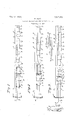
- Fig. 1 is a sectional elevation of approximately one-half of a device illustrating my presentinvention. In this figure the parts are shown in their normal position of rest.
- Fig. 2 is a similar view showing the position of parts when a buiiing thrust is applied thereto, and
- Fig. 3 is also a similar view in which the position 'which the ⁇ parts assume when a tractive thrust is applied thereto is shown.
- Fig. 4 is a partial plan showing. the inner ends of the draft and buffer rods and the sleeve in which they are slidably mounted.
- the -part a diagrammaticallyindicates anI automatic coupling head or the part for connection therewithv in avehicle.
- the half b of the draw rod extends through the headstock or buffer beam and the other transverse members of the underfrafne up to the centre of the vehicle, where it is longitudinally movable in the connecting member d which is adapted to slide to a limited ability of the rod b in the connecting member is limited byy means of a cotter o fixed to the rod and sliding in longitudinal slots Qi, g of the part d.
- the other half of the draw rod the inner end of which is shown in part at the right of the drawing, possesses the same symmetrical arrangement.
- the part of the draw rod traversing the reference to buiiing -veh icle'.
- the longitudinal displace-y beam has an angular cross section in order to prevent' any twisting4 or turning of the rod.
- the remaining portion of the rod is or may be of round cross section.
- bearing headstock or bu'er i lmembers e andlf are suitably secured to a central or longitudinal member n forming part of the under frame or body of the J ourn'ale'd in these bearings e and f are tubular lsleeves g and Zi.
- the rod Z) passes through theVA sleeves g and h. and these sleeves are fixed in position4 on the rod by means of cotter pins i. and j respectively or otherwise.
- abutment plates 7c and Z Bearing against the facing ends of the sleeves g andhl are abutment plates 7c and Z which are displaceable upon the draw rod and between which there is located a helical spring m.
- A- bearing r' attached to the said central longitudinal member n, serves to In the position of rest shown in Fig. 1 the abutment plates c and Z arepressed by the spring m not only against the bearings e andf but also against the sleeves g and h guided therein which is the normal position ofthe parts of the apparatus.
- the dimensions of the sliding parts are preferably so selected that upon buffing thrusts occurring at both ends of the vehicle, that is to say upon simultaneous pressing. in of both paits of the draw rod, the inner ends of said rod parts will strike together. within the connecting member (Z prior to the complete compression of the springs m.
- the movement is effected by the cotter y' ⁇ bearing against the'bearing' f.
- the amount which the draw rod parts can move apart from each other upon the occurrence yof a draw or pull, is-determined by the length. ⁇ of the slots p, Q in theconnecting member af kand in which the draw rod cotters 0 are guided. rfhis amount is preferably smaller than the sum total of the amounts of play of both springs m.
Description
Patented May 12, 1925.
l ALMA, a citizen of the draw device comprisinga drawrod intwo also to bufiing or compressing UNITED STATESI MAXIMILIAN ALMA, OF VIENNA, AUSTRIA.
Application-filed July 13, 1922. Serial No. 574,777.
To aZZ 'whomz't may concern:
Be it known that I, Dr. MAXIMILIAN Republic of Austria, and residing at Vienna, Austria, have in-A vented certain new and useful-Improvements in a Buing and 'Draw Gear for Railway Vehicles, of which the following is a specification.` v-
This invention has and draw gear for railway vehicles and the like and hasv for its object to provide an improved yieldngcontinuous buiiing and parts that are displaceably connected at the centre of the vehicle and subjected to the influence of springs. l
` According to the invention the springs are s o disposed, between sleeves mounted -to slide in {iX-ed bearings and connected with the draw-rod, that the said springs will press against the bearings in they case of stresses duenot only to draw vor tracti-ve e'orts but thrusts.
' In the-drawing, Fig. 1 is a sectional elevation of approximately one-half of a device illustrating my presentinvention. In this figure the parts are shown in their normal position of rest.
Fig. 2 is a similar view showing the position of parts when a buiiing thrust is applied thereto, and
Fig. 3 is also a similar view in which the position 'which the `parts assume when a tractive thrust is applied thereto is shown.
And Fig. 4 is a partial plan showing. the inner ends of the draft and buffer rods and the sleeve in which they are slidably mounted.
The -part a diagrammaticallyindicates anI automatic coupling head or the part for connection therewithv in avehicle. From this part the half b of the draw rod extends through the headstock or buffer beam and the other transverse members of the underfrafne up to the centre of the vehicle, where it is longitudinally movable in the connecting member d which is adapted to slide to a limited ability of the rod b in the connecting member is limited byy means of a cotter o fixed to the rod and sliding in longitudinal slots Qi, g of the part d. The other half of the draw rod, the inner end of which is shown in part at the right of the drawing, possesses the same symmetrical arrangement. The part of the draw rod traversing the reference to buiiing -veh icle'.
guide the draw rod.
extent, The longitudinal displace-y beam has an angular cross section in order to prevent' any twisting4 or turning of the rod. The remaining portion of the rod is or may be of round cross section.'
As illustrated in the' drawing, bearing headstock or bu'er i lmembers e andlf are suitably secured to a central or longitudinal member n forming part of the under frame or body of the J ourn'ale'd in these bearings e and f are tubular lsleeves g and Zi. rThe rod Z) passes through theVA sleeves g and h. and these sleeves are fixed in position4 on the rod by means of cotter pins i. and j respectively or otherwise.
Bearing against the facing ends of the sleeves g andhl are abutment plates 7c and Z which are displaceable upon the draw rod and between which there is located a helical spring m. A- bearing r', attached to the said central longitudinal member n, serves to In the position of rest shown in Fig. 1 the abutment plates c and Z arepressed by the spring m not only against the bearings e andf but also against the sleeves g and h guided therein which is the normal position ofthe parts of the apparatus.
Upon the occurrence of a'buliing inward thrust (Fig. 2) the rod b is moved inwardly and by means of the sleeve g the abutment plate 7c is correspondingly moved so that the spring m is compressed towards the abutment plate Z which at this time is held against movement by the fixed bearing The limitation of the displacement is eiected bythe impact of the cotter i upon the bearing e or by impactof the ycoupling head a upon the c or both.
\ The dimensions of the sliding parts are preferably so selected that upon buffing thrusts occurring at both ends of the vehicle, that is to say upon simultaneous pressing. in of both paits of the draw rod, the inner ends of said rod parts will strike together. within the connecting member (Z prior to the complete compression of the springs m.
Upon the occurrence of a pull -or draw (Fig. 3) the draw rod will be pulled outwardly and, by means of the sleeve 7i, the abutment plate Z will be correspondingly moved with simultaneous compression of the spring'm, towards, the abutmentv plate is which is at this time-prevented from movement by the bearing e. The limitation of push or 5 headstock or buffer beam 9.
l` the movement is effected by the cotter y' `bearing against the'bearing' f. The amount which the draw rod parts can move apart from each other upon the occurrence yof a draw or pull, is-determined by the length.` of the slots p, Q in theconnecting member af kand in which the draw rod cotters 0 are guided. rfhis amount is preferably smaller than the sum total of the amounts of play of both springs m. With a slight' degree of displaceability of the connecting member d (between two draw rod bearings) the limitation of the movement of a draw rod part is effected in any'l caseby the cotter o the connecting member al being pressed against the corresponding bearing.
'It will therefore be apparent that in the apparatus as hereinbefore described relatively slight tensile or compression strains are absorbedby the springs m and a portion of the same may be transmitted from one end of the vehicle to the other through the body or frame thereof, whereas strains of either nature when greater than a predetermined amount are transmitted direct-1y through the bar or rod members b.
In case 'the two guide bearings r are ar- 4 ranged so close together that the' displace` ability of the connecting member d between them is only very slight, then the dimensions can be so selected that the limitation of the.
movement of a draw rod part b in a direction out of the vehicleinstead of being effected by theimpact of the cotter j upon ythe bearing f-can be eected by the impact of the cotter o upon the end of the slot in the connecting member d the said connecting member d being pressed against the bearing r.
What I claim is:
1. Ina vehicle and in combination with the .frame thereof, draft and bu'er rods in alignment and extending longitudinally of the frame of the vehicle, a sleeve in which the adjacent ends of the` said draft and buffer rods are slidable, means for mounting the said draft and buffer rods on the frame of the vehicle, and means for yieldingly maintaining the said draft and buffer rods in an initial position in which the adjacentends thereof are spaced within the said sleeve v permitting the said rods to be moved toward and away from each other to a predetermined extent whereby buffer stresses applied substantially simultaneously to the outer portions ofthe saidrods move the same toward each other to bring the innerends of the said rods together. and draft stresses applied substantially simultaneously to the en portions of the said rods move the same apart connecting them to the said sleeve through which said stresses are'then applied independently of the vehicle frame.
v 2. In a vehicle and in. combination with the frame thereof, draft and buffer rodsin valignment and extending longitudinally of the frame of the vehicle, bearings attached to the frame of the vehicle for each draft and. buffer rod, cylindric l members movable in each bearing with a d aftand buffer rod passing through the same, means for connecting each draft land buffer rod to the cylindrical membersassociated therewith, a
- yielding device associated with each draft and buffer rod and extending between the bearings .in which the cylindrical members therefor are mounted, and a sleeve within which thepositions in which their adjacent ends are i spaced within the said sleeve whereby when buffer stresses of. greater than a predetermined force are applied substantially simultaneously Vto the outer portions of the said rods the rods are moved toward each other until their inner adjacent ends contact when such buffer'stress'es are transmitted directly through the said rods and whereby when draft stresses greater than a predetermined force are applied to the outer'portions of the said rods the same are moved apart a predetermined extent to -connect withv the said sleeve whereby through the sleeve the said stresses are 4transmitted directly from one bar'to the other independently of the frame of the vehicle.
3. In a vehicle and in combination with the frame thereof, sets of bearings attached vto the frame adjacent both ends thereof, a
cylindrical member slidable in each bearing' of both sets thereof, draft and buffer rods in alignment vand extending through the said cylindrical members, means for conthe draft and vbuffer rods may be moved away from each other whereby when buffer stresses sufficient to overcome the action of the said yielding devices are applied sub stantially simultaneously to the opposite.
outer portions of the said draft and buffer rods these rods are moved toward each otherv to bring the inner ends into contact to transmitl said stresses directly through the said rods and whereby when draft stresses of sufficient force to overcome the action of the said yielding devices are applied substantiallysimultaneously to the said rods the rods are moved apart to the extent permitted by the means forlimiting the same CII through the said sleeve.
4E. In a vehicle and in combination with the frame thereof, sets of bearings attached to the frame adjacent both ends thereof, a cylindrical member slidable in each bearing of both sets thereof,vdraft and buffer rods in alignment and extending through the said cylindrical members, means for connecting each draft and buffer rod with the cylindrical members throughwhich it passes, a spring associated with each draft and buffer rod and located between the bearings for the cylindrical members through which each draft and buffer rod passes, a sleeve 1n which the inner or adjacent ends of the said draft and buffer rods vare slidable toward and away from eachother, and means fo-r determining the extent to which the draft and buffer rods may bev moved away from each tact to transmit said other whereby when buffer stresses sufficient to overcome the action of the said springs are applied substantially simultaneously to the opposite outer portions of the said draft and buffer rods these rods are moved toward each other to bring the inner ends into constresses directly through the said rods and whereby when draft stresses of sufficient force to overcome the action of the said springs are applied substantially simultaneously to the said' rods the rods are moved apart to the extent permitted by the means for limiting the same to cause the said draft stresses to be transmitted directly from one rod to the other through the said sleeve.
5. In a vehicle and in combination with the frame thereof,.sets of bearings attached to the frame adjacent both ends thereofv` a cylindrical member slidable in each bearing of both sets thereof, draft and buffer rods in alignment and extending through the Said cylindrical members, means for connecting each draft and buffer I 'od with the cylindricalmembers through which it passes, a spring associated with each draft andbuffer rod and located between the bearings for the cylindrical members through which each draft and buffer rod passes, a sleeve within which the inner ends ofthe said draft and buffer rods are slidable, the sleeve beingpro-- vided with longitudinal'slots, and pins passing through the inner ends of the said rods and moving in the said slots, the s'aid springs normally maintaining the yrods in the position in which the innerendsthereof are spaced within the said sleeve" whereby when buffer stresses of greater than a predetermined force are applied substantially simultaneously to the outer portions of the said rods the rods are moved toward each other causing the ends thereof to come into Contact whereby the said stresses are transmitted directlythrough the said rods and' 'whereby when draft stresses of a` greater than a predetermined force are applied substantially simultaneously to the said rods the same are moved apart bringing the said pins into Contact with theextremities of the slots in the sleeve to cause the said stresses` to be transmitted directly through the sleeve from one rod to( another. A
In testimony whereof I aiiX my signatur in presence of two witnesses.
Dn. hLAXIMILIAN ALMA
Priority Applications (1)
| Application Number | Priority Date | Filing Date | Title |
|---|---|---|---|
| US574777A US1537726A (en) | 1922-03-18 | 1922-07-13 | Buffing and draw gear for railway vehicles |
Applications Claiming Priority (2)
| Application Number | Priority Date | Filing Date | Title |
|---|---|---|---|
| AT195034X | 1922-03-18 | ||
| US574777A US1537726A (en) | 1922-03-18 | 1922-07-13 | Buffing and draw gear for railway vehicles |
Publications (1)
| Publication Number | Publication Date |
|---|---|
| US1537726A true US1537726A (en) | 1925-05-12 |
Family
ID=25607625
Family Applications (1)
| Application Number | Title | Priority Date | Filing Date |
|---|---|---|---|
| US574777A Expired - Lifetime US1537726A (en) | 1922-03-18 | 1922-07-13 | Buffing and draw gear for railway vehicles |
Country Status (1)
| Country | Link |
|---|---|
| US (1) | US1537726A (en) |
Cited By (4)
| Publication number | Priority date | Publication date | Assignee | Title |
|---|---|---|---|---|
| US2744638A (en) * | 1952-05-09 | 1956-05-08 | Waugh Equipment Co | Cushion underframe |
| USRE45141E1 (en) | 2001-12-28 | 2014-09-23 | Trisa Holding Ag | Toothbrush and process for producing such a toothbrush |
| US10405642B2 (en) | 2002-12-19 | 2019-09-10 | Trisa Holding Ag | Toothbrush and process for producing the same |
| US11219303B2 (en) | 2016-04-20 | 2022-01-11 | Trisa Holding Ag | Brush product and method for the production thereof |
-
1922
- 1922-07-13 US US574777A patent/US1537726A/en not_active Expired - Lifetime
Cited By (5)
| Publication number | Priority date | Publication date | Assignee | Title |
|---|---|---|---|---|
| US2744638A (en) * | 1952-05-09 | 1956-05-08 | Waugh Equipment Co | Cushion underframe |
| USRE45141E1 (en) | 2001-12-28 | 2014-09-23 | Trisa Holding Ag | Toothbrush and process for producing such a toothbrush |
| USRE47468E1 (en) | 2001-12-28 | 2019-07-02 | Trisa Holding Ag | Toothbrush and process for producing such a toothbrush |
| US10405642B2 (en) | 2002-12-19 | 2019-09-10 | Trisa Holding Ag | Toothbrush and process for producing the same |
| US11219303B2 (en) | 2016-04-20 | 2022-01-11 | Trisa Holding Ag | Brush product and method for the production thereof |
Similar Documents
| Publication | Publication Date | Title |
|---|---|---|
| US1537726A (en) | Buffing and draw gear for railway vehicles | |
| US1853857A (en) | Central buffing and drawgear for railway vehicles | |
| US2022253A (en) | Draft gear for railway vehicles | |
| US2003645A (en) | Mine car bumper | |
| US2965246A (en) | Draft gear rigging | |
| US1323787A (en) | richards and d | |
| US2054005A (en) | Car coupler | |
| US2276167A (en) | Mine car bumper | |
| US2474919A (en) | Draft rigging shock absorber | |
| US1663994A (en) | Friction shock-absorbing mechanism | |
| US1947316A (en) | Draft rigging | |
| US1338893A (en) | Friction draft-gear | |
| US2089208A (en) | Spring bumper | |
| USRE8095E (en) | Edward l | |
| US1499152A (en) | Resilient device for vehicles | |
| US2043344A (en) | Continuous draft gear | |
| US1637070A (en) | Friction shock-absorbing mechanism | |
| US2720320A (en) | Combined friction and rubber shock absorbing mechanisms | |
| US566935A (en) | Draft-rigging | |
| DE1945906A1 (en) | Pulling and pushing device for central buffer couplings of rail vehicles | |
| DE439262C (en) | Buffer with a shell-shaped buffer pusher | |
| DE552991C (en) | Resilient pulling and pushing device for railway vehicles | |
| US1169435A (en) | Draft-rigging for railway-cars. | |
| US1265414A (en) | Draft-rigging for railway-cars. | |
| US1826837A (en) | Draft and buffing gear |