EP3235445A1 - Surgical instrument comprising a lockout - Google Patents
Surgical instrument comprising a lockout Download PDFInfo
- Publication number
- EP3235445A1 EP3235445A1 EP17166579.7A EP17166579A EP3235445A1 EP 3235445 A1 EP3235445 A1 EP 3235445A1 EP 17166579 A EP17166579 A EP 17166579A EP 3235445 A1 EP3235445 A1 EP 3235445A1
- Authority
- EP
- European Patent Office
- Prior art keywords
- firing
- jaw
- staple cartridge
- lockout
- firing member
- Prior art date
- Legal status (The legal status is an assumption and is not a legal conclusion. Google has not performed a legal analysis and makes no representation as to the accuracy of the status listed.)
- Granted
Links
- 238000010304 firing Methods 0.000 claims abstract description 650
- 239000012636 effector Substances 0.000 claims description 96
- 238000005520 cutting process Methods 0.000 claims description 42
- 238000004891 communication Methods 0.000 claims description 23
- 230000036961 partial effect Effects 0.000 description 47
- 230000005291 magnetic effect Effects 0.000 description 36
- 230000033001 locomotion Effects 0.000 description 34
- 239000004020 conductor Substances 0.000 description 27
- 238000001514 detection method Methods 0.000 description 17
- 239000000463 material Substances 0.000 description 15
- 238000000034 method Methods 0.000 description 13
- 230000000712 assembly Effects 0.000 description 10
- 238000000429 assembly Methods 0.000 description 10
- 238000000418 atomic force spectrum Methods 0.000 description 10
- 230000014759 maintenance of location Effects 0.000 description 9
- 230000008859 change Effects 0.000 description 8
- 239000012530 fluid Substances 0.000 description 7
- 230000001133 acceleration Effects 0.000 description 5
- 238000006073 displacement reaction Methods 0.000 description 5
- 230000005855 radiation Effects 0.000 description 5
- 230000006870 function Effects 0.000 description 4
- 238000009434 installation Methods 0.000 description 4
- 239000002184 metal Substances 0.000 description 4
- 229910052751 metal Inorganic materials 0.000 description 4
- 238000004140 cleaning Methods 0.000 description 3
- 230000000670 limiting effect Effects 0.000 description 3
- 230000004044 response Effects 0.000 description 3
- 230000000717 retained effect Effects 0.000 description 3
- 238000001356 surgical procedure Methods 0.000 description 3
- XEEYBQQBJWHFJM-UHFFFAOYSA-N Iron Chemical compound [Fe] XEEYBQQBJWHFJM-UHFFFAOYSA-N 0.000 description 2
- PXHVJJICTQNCMI-UHFFFAOYSA-N Nickel Chemical compound [Ni] PXHVJJICTQNCMI-UHFFFAOYSA-N 0.000 description 2
- 230000000903 blocking effect Effects 0.000 description 2
- 238000013016 damping Methods 0.000 description 2
- 230000006872 improvement Effects 0.000 description 2
- 230000007246 mechanism Effects 0.000 description 2
- 230000004048 modification Effects 0.000 description 2
- 238000012986 modification Methods 0.000 description 2
- 238000012544 monitoring process Methods 0.000 description 2
- 230000037361 pathway Effects 0.000 description 2
- 230000008569 process Effects 0.000 description 2
- 238000013519 translation Methods 0.000 description 2
- 241000894006 Bacteria Species 0.000 description 1
- IAYPIBMASNFSPL-UHFFFAOYSA-N Ethylene oxide Chemical compound C1CO1 IAYPIBMASNFSPL-UHFFFAOYSA-N 0.000 description 1
- 230000005355 Hall effect Effects 0.000 description 1
- 239000004775 Tyvek Substances 0.000 description 1
- 229920000690 Tyvek Polymers 0.000 description 1
- 230000006978 adaptation Effects 0.000 description 1
- 238000013459 approach Methods 0.000 description 1
- 230000008901 benefit Effects 0.000 description 1
- 230000002950 deficient Effects 0.000 description 1
- 230000000694 effects Effects 0.000 description 1
- 239000013536 elastomeric material Substances 0.000 description 1
- 230000005294 ferromagnetic effect Effects 0.000 description 1
- 238000007667 floating Methods 0.000 description 1
- 230000002439 hemostatic effect Effects 0.000 description 1
- 230000001939 inductive effect Effects 0.000 description 1
- 229910052742 iron Inorganic materials 0.000 description 1
- 238000012830 laparoscopic surgical procedure Methods 0.000 description 1
- 238000004519 manufacturing process Methods 0.000 description 1
- 238000012978 minimally invasive surgical procedure Methods 0.000 description 1
- 229910052759 nickel Inorganic materials 0.000 description 1
- 238000002355 open surgical procedure Methods 0.000 description 1
- 150000002978 peroxides Chemical class 0.000 description 1
- 230000002829 reductive effect Effects 0.000 description 1
- 230000001105 regulatory effect Effects 0.000 description 1
- 230000002441 reversible effect Effects 0.000 description 1
- 150000003839 salts Chemical class 0.000 description 1
- 238000007789 sealing Methods 0.000 description 1
- 229910001220 stainless steel Inorganic materials 0.000 description 1
- 239000010935 stainless steel Substances 0.000 description 1
- 230000001954 sterilising effect Effects 0.000 description 1
- 238000004659 sterilization and disinfection Methods 0.000 description 1
- 238000012546 transfer Methods 0.000 description 1
- 230000001052 transient effect Effects 0.000 description 1
- 230000007704 transition Effects 0.000 description 1
- XLYOFNOQVPJJNP-UHFFFAOYSA-N water Substances O XLYOFNOQVPJJNP-UHFFFAOYSA-N 0.000 description 1
- 238000003466 welding Methods 0.000 description 1
Images


Classifications
-
- A—HUMAN NECESSITIES
- A61—MEDICAL OR VETERINARY SCIENCE; HYGIENE
- A61B—DIAGNOSIS; SURGERY; IDENTIFICATION
- A61B17/00—Surgical instruments, devices or methods, e.g. tourniquets
- A61B17/068—Surgical staplers, e.g. containing multiple staples or clamps
- A61B17/072—Surgical staplers, e.g. containing multiple staples or clamps for applying a row of staples in a single action, e.g. the staples being applied simultaneously
- A61B17/07207—Surgical staplers, e.g. containing multiple staples or clamps for applying a row of staples in a single action, e.g. the staples being applied simultaneously the staples being applied sequentially
-
- A—HUMAN NECESSITIES
- A61—MEDICAL OR VETERINARY SCIENCE; HYGIENE
- A61B—DIAGNOSIS; SURGERY; IDENTIFICATION
- A61B17/00—Surgical instruments, devices or methods, e.g. tourniquets
- A61B17/068—Surgical staplers, e.g. containing multiple staples or clamps
-
- A—HUMAN NECESSITIES
- A61—MEDICAL OR VETERINARY SCIENCE; HYGIENE
- A61B—DIAGNOSIS; SURGERY; IDENTIFICATION
- A61B17/00—Surgical instruments, devices or methods, e.g. tourniquets
- A61B17/068—Surgical staplers, e.g. containing multiple staples or clamps
- A61B17/072—Surgical staplers, e.g. containing multiple staples or clamps for applying a row of staples in a single action, e.g. the staples being applied simultaneously
-
- A—HUMAN NECESSITIES
- A61—MEDICAL OR VETERINARY SCIENCE; HYGIENE
- A61B—DIAGNOSIS; SURGERY; IDENTIFICATION
- A61B17/00—Surgical instruments, devices or methods, e.g. tourniquets
- A61B17/10—Surgical instruments, devices or methods, e.g. tourniquets for applying or removing wound clamps, e.g. containing only one clamp or staple; Wound clamp magazines
- A61B17/105—Wound clamp magazines
-
- A—HUMAN NECESSITIES
- A61—MEDICAL OR VETERINARY SCIENCE; HYGIENE
- A61B—DIAGNOSIS; SURGERY; IDENTIFICATION
- A61B17/00—Surgical instruments, devices or methods, e.g. tourniquets
- A61B2017/00017—Electrical control of surgical instruments
-
- A—HUMAN NECESSITIES
- A61—MEDICAL OR VETERINARY SCIENCE; HYGIENE
- A61B—DIAGNOSIS; SURGERY; IDENTIFICATION
- A61B17/00—Surgical instruments, devices or methods, e.g. tourniquets
- A61B2017/00367—Details of actuation of instruments, e.g. relations between pushing buttons, or the like, and activation of the tool, working tip, or the like
- A61B2017/00398—Details of actuation of instruments, e.g. relations between pushing buttons, or the like, and activation of the tool, working tip, or the like using powered actuators, e.g. stepper motors, solenoids
-
- A—HUMAN NECESSITIES
- A61—MEDICAL OR VETERINARY SCIENCE; HYGIENE
- A61B—DIAGNOSIS; SURGERY; IDENTIFICATION
- A61B17/00—Surgical instruments, devices or methods, e.g. tourniquets
- A61B2017/0046—Surgical instruments, devices or methods, e.g. tourniquets with a releasable handle; with handle and operating part separable
- A61B2017/00473—Distal part, e.g. tip or head
-
- A—HUMAN NECESSITIES
- A61—MEDICAL OR VETERINARY SCIENCE; HYGIENE
- A61B—DIAGNOSIS; SURGERY; IDENTIFICATION
- A61B17/00—Surgical instruments, devices or methods, e.g. tourniquets
- A61B2017/00477—Coupling
-
- A—HUMAN NECESSITIES
- A61—MEDICAL OR VETERINARY SCIENCE; HYGIENE
- A61B—DIAGNOSIS; SURGERY; IDENTIFICATION
- A61B17/00—Surgical instruments, devices or methods, e.g. tourniquets
- A61B2017/00526—Methods of manufacturing
-
- A—HUMAN NECESSITIES
- A61—MEDICAL OR VETERINARY SCIENCE; HYGIENE
- A61B—DIAGNOSIS; SURGERY; IDENTIFICATION
- A61B17/00—Surgical instruments, devices or methods, e.g. tourniquets
- A61B2017/00535—Surgical instruments, devices or methods, e.g. tourniquets pneumatically or hydraulically operated
- A61B2017/00544—Surgical instruments, devices or methods, e.g. tourniquets pneumatically or hydraulically operated pneumatically
-
- A—HUMAN NECESSITIES
- A61—MEDICAL OR VETERINARY SCIENCE; HYGIENE
- A61B—DIAGNOSIS; SURGERY; IDENTIFICATION
- A61B17/00—Surgical instruments, devices or methods, e.g. tourniquets
- A61B2017/00681—Aspects not otherwise provided for
- A61B2017/00734—Aspects not otherwise provided for battery operated
-
- A—HUMAN NECESSITIES
- A61—MEDICAL OR VETERINARY SCIENCE; HYGIENE
- A61B—DIAGNOSIS; SURGERY; IDENTIFICATION
- A61B17/00—Surgical instruments, devices or methods, e.g. tourniquets
- A61B2017/00831—Material properties
- A61B2017/00876—Material properties magnetic
-
- A—HUMAN NECESSITIES
- A61—MEDICAL OR VETERINARY SCIENCE; HYGIENE
- A61B—DIAGNOSIS; SURGERY; IDENTIFICATION
- A61B17/00—Surgical instruments, devices or methods, e.g. tourniquets
- A61B17/068—Surgical staplers, e.g. containing multiple staples or clamps
- A61B17/072—Surgical staplers, e.g. containing multiple staples or clamps for applying a row of staples in a single action, e.g. the staples being applied simultaneously
- A61B2017/07214—Stapler heads
- A61B2017/07257—Stapler heads characterised by its anvil
-
- A—HUMAN NECESSITIES
- A61—MEDICAL OR VETERINARY SCIENCE; HYGIENE
- A61B—DIAGNOSIS; SURGERY; IDENTIFICATION
- A61B17/00—Surgical instruments, devices or methods, e.g. tourniquets
- A61B17/068—Surgical staplers, e.g. containing multiple staples or clamps
- A61B17/072—Surgical staplers, e.g. containing multiple staples or clamps for applying a row of staples in a single action, e.g. the staples being applied simultaneously
- A61B2017/07214—Stapler heads
- A61B2017/07271—Stapler heads characterised by its cartridge
-
- A—HUMAN NECESSITIES
- A61—MEDICAL OR VETERINARY SCIENCE; HYGIENE
- A61B—DIAGNOSIS; SURGERY; IDENTIFICATION
- A61B17/00—Surgical instruments, devices or methods, e.g. tourniquets
- A61B17/068—Surgical staplers, e.g. containing multiple staples or clamps
- A61B17/072—Surgical staplers, e.g. containing multiple staples or clamps for applying a row of staples in a single action, e.g. the staples being applied simultaneously
- A61B2017/07214—Stapler heads
- A61B2017/07278—Stapler heads characterised by its sled or its staple holder
-
- A—HUMAN NECESSITIES
- A61—MEDICAL OR VETERINARY SCIENCE; HYGIENE
- A61B—DIAGNOSIS; SURGERY; IDENTIFICATION
- A61B17/00—Surgical instruments, devices or methods, e.g. tourniquets
- A61B17/068—Surgical staplers, e.g. containing multiple staples or clamps
- A61B17/072—Surgical staplers, e.g. containing multiple staples or clamps for applying a row of staples in a single action, e.g. the staples being applied simultaneously
- A61B2017/07214—Stapler heads
- A61B2017/07285—Stapler heads characterised by its cutter
-
- A—HUMAN NECESSITIES
- A61—MEDICAL OR VETERINARY SCIENCE; HYGIENE
- A61B—DIAGNOSIS; SURGERY; IDENTIFICATION
- A61B17/00—Surgical instruments, devices or methods, e.g. tourniquets
- A61B17/28—Surgical forceps
- A61B17/29—Forceps for use in minimally invasive surgery
- A61B2017/2901—Details of shaft
- A61B2017/2902—Details of shaft characterized by features of the actuating rod
- A61B2017/2903—Details of shaft characterized by features of the actuating rod transferring rotary motion
-
- A—HUMAN NECESSITIES
- A61—MEDICAL OR VETERINARY SCIENCE; HYGIENE
- A61B—DIAGNOSIS; SURGERY; IDENTIFICATION
- A61B17/00—Surgical instruments, devices or methods, e.g. tourniquets
- A61B17/28—Surgical forceps
- A61B17/29—Forceps for use in minimally invasive surgery
- A61B2017/2926—Details of heads or jaws
- A61B2017/2927—Details of heads or jaws the angular position of the head being adjustable with respect to the shaft
-
- A—HUMAN NECESSITIES
- A61—MEDICAL OR VETERINARY SCIENCE; HYGIENE
- A61B—DIAGNOSIS; SURGERY; IDENTIFICATION
- A61B17/00—Surgical instruments, devices or methods, e.g. tourniquets
- A61B17/28—Surgical forceps
- A61B17/29—Forceps for use in minimally invasive surgery
- A61B2017/2926—Details of heads or jaws
- A61B2017/2932—Transmission of forces to jaw members
- A61B2017/2943—Toothed members, e.g. rack and pinion
-
- A—HUMAN NECESSITIES
- A61—MEDICAL OR VETERINARY SCIENCE; HYGIENE
- A61B—DIAGNOSIS; SURGERY; IDENTIFICATION
- A61B17/00—Surgical instruments, devices or methods, e.g. tourniquets
- A61B17/28—Surgical forceps
- A61B17/29—Forceps for use in minimally invasive surgery
- A61B2017/2946—Locking means
-
- A—HUMAN NECESSITIES
- A61—MEDICAL OR VETERINARY SCIENCE; HYGIENE
- A61B—DIAGNOSIS; SURGERY; IDENTIFICATION
- A61B90/00—Instruments, implements or accessories specially adapted for surgery or diagnosis and not covered by any of the groups A61B1/00 - A61B50/00, e.g. for luxation treatment or for protecting wound edges
- A61B90/03—Automatic limiting or abutting means, e.g. for safety
- A61B2090/033—Abutting means, stops, e.g. abutting on tissue or skin
- A61B2090/034—Abutting means, stops, e.g. abutting on tissue or skin abutting on parts of the device itself
-
- A—HUMAN NECESSITIES
- A61—MEDICAL OR VETERINARY SCIENCE; HYGIENE
- A61B—DIAGNOSIS; SURGERY; IDENTIFICATION
- A61B90/00—Instruments, implements or accessories specially adapted for surgery or diagnosis and not covered by any of the groups A61B1/00 - A61B50/00, e.g. for luxation treatment or for protecting wound edges
- A61B90/08—Accessories or related features not otherwise provided for
- A61B2090/0803—Counting the number of times an instrument is used
-
- A—HUMAN NECESSITIES
- A61—MEDICAL OR VETERINARY SCIENCE; HYGIENE
- A61B—DIAGNOSIS; SURGERY; IDENTIFICATION
- A61B90/00—Instruments, implements or accessories specially adapted for surgery or diagnosis and not covered by any of the groups A61B1/00 - A61B50/00, e.g. for luxation treatment or for protecting wound edges
- A61B90/08—Accessories or related features not otherwise provided for
- A61B2090/0807—Indication means
- A61B2090/0808—Indication means for indicating correct assembly of components, e.g. of the surgical apparatus
-
- A—HUMAN NECESSITIES
- A61—MEDICAL OR VETERINARY SCIENCE; HYGIENE
- A61B—DIAGNOSIS; SURGERY; IDENTIFICATION
- A61B90/00—Instruments, implements or accessories specially adapted for surgery or diagnosis and not covered by any of the groups A61B1/00 - A61B50/00, e.g. for luxation treatment or for protecting wound edges
- A61B90/08—Accessories or related features not otherwise provided for
- A61B2090/0807—Indication means
- A61B2090/0811—Indication means for the position of a particular part of an instrument with respect to the rest of the instrument, e.g. position of the anvil of a stapling instrument
-
- A—HUMAN NECESSITIES
- A61—MEDICAL OR VETERINARY SCIENCE; HYGIENE
- A61B—DIAGNOSIS; SURGERY; IDENTIFICATION
- A61B90/00—Instruments, implements or accessories specially adapted for surgery or diagnosis and not covered by any of the groups A61B1/00 - A61B50/00, e.g. for luxation treatment or for protecting wound edges
- A61B90/08—Accessories or related features not otherwise provided for
- A61B2090/0814—Preventing re-use
-
- A—HUMAN NECESSITIES
- A61—MEDICAL OR VETERINARY SCIENCE; HYGIENE
- A61B—DIAGNOSIS; SURGERY; IDENTIFICATION
- A61B90/00—Instruments, implements or accessories specially adapted for surgery or diagnosis and not covered by any of the groups A61B1/00 - A61B50/00, e.g. for luxation treatment or for protecting wound edges
- A61B90/90—Identification means for patients or instruments, e.g. tags
- A61B90/98—Identification means for patients or instruments, e.g. tags using electromagnetic means, e.g. transponders
Definitions
- the present invention relates to surgical instruments and, in various arrangements, to surgical stapling and cutting instruments and staple cartridges for use therewith that are designed to staple and cut tissue.
- proximal and distal are used herein with reference to a clinician manipulating the handle portion of the surgical instrument.
- proximal refers to the portion closest to the clinician and the term “distal” refers to the portion located away from the clinician.
- distal refers to the portion located away from the clinician.
- spatial terms such as “vertical”, “horizontal”, “up”, and “down” may be used herein with respect to the drawings.
- surgical instruments are used in many orientations and positions, and these terms are not intended to be limiting and/or absolute.
- Various exemplary devices and methods are provided for performing laparoscopic and minimally invasive surgical procedures.
- the various methods and devices disclosed herein can be used in numerous surgical procedures and applications including, for example, in connection with open surgical procedures.
- the various instruments disclosed herein can be inserted into a body in any way, such as through a natural orifice, through an incision or puncture hole formed in tissue, etc.
- the working portions or end effector portions of the instruments can be inserted directly into a patient's body or can be inserted through an access device that has a working channel through which the end effector and elongate shaft of a surgical instrument can be advanced.
- a surgical stapling system can comprise a shaft and an end effector extending from the shaft.
- the end effector comprises a first jaw and a second jaw.
- the first jaw comprises a staple cartridge.
- the staple cartridge is insertable into and removable from the first jaw; however, other embodiments are envisioned in which a staple cartridge is not removable from, or at least readily replaceable from, the first jaw.
- the second jaw comprises an anvil configured to deform staples ejected from the staple cartridge.
- the second jaw is pivotable relative to the first jaw about a closure axis; however, other embodiments are envisioned in which first jaw is pivotable relative to the second jaw.
- the surgical stapling system further comprises an articulation joint configured to permit the end effector to be rotated, or articulated, relative to the shaft.
- the end effector is rotatable about an articulation axis extending through the articulation joint. Other embodiments are envisioned which do not include an articulation joint.
- the staple cartridge comprises a cartridge body.
- the cartridge body includes a proximal end, a distal end, and a deck extending between the proximal end and the distal end.
- the staple cartridge is positioned on a first side of the tissue to be stapled and the anvil is positioned on a second side of the tissue.
- the anvil is moved toward the staple cartridge to compress and clamp the tissue against the deck.
- staples removably stored in the cartridge body can be deployed into the tissue.
- the cartridge body includes staple cavities defined therein wherein staples are removably stored in the staple cavities.
- the staple cavities are arranged in six longitudinal rows. Three rows of staple cavities are positioned on a first side of a longitudinal slot and three rows of staple cavities are positioned on a second side of the longitudinal slot. Other arrangements of staple cavities and staples may be possible.
- the staples are supported by staple drivers in the cartridge body.
- the drivers are movable between a first, or unfired position, and a second, or fired, position to eject the staples from the staple cavities.
- the drivers are retained in the cartridge body by a retainer which extends around the bottom of the cartridge body and includes resilient members configured to grip the cartridge body and hold the retainer to the cartridge body.
- the drivers are movable between their unfired positions and their fired positions by a sled.
- the sled is movable between a proximal position adjacent the proximal end and a distal position adjacent the distal end.
- the sled comprises a plurality of ramped surfaces configured to slide under the drivers and lift the drivers, and the staples supported thereon, toward the anvil.
- the sled is moved distally by a firing member.
- the firing member is configured to contact the sled and push the sled toward the distal end.
- the longitudinal slot defined in the cartridge body is configured to receive the firing member.
- the anvil also includes a slot configured to receive the firing member.
- the firing member further comprises a first cam which engages the first jaw and a second cam which engages the second jaw. As the firing member is advanced distally, the first cam and the second cam can control the distance, or tissue gap, between the deck of the staple cartridge and the anvil.
- the firing member also comprises a knife configured to incise the tissue captured intermediate the staple cartridge and the anvil. It is desirable for the knife to be positioned at least partially proximal to the ramped surfaces such that the staples are ejected ahead of the knife.
- Certain surgical stapling and cutting end effectors described herein include an elongate channel configured to removably receive a staple cartridge that has surgical staples stored therein.
- the staple cartridge includes ejectors, or drivers, movably supported within a cartridge body of the staple cartridge which are each configured to support one or more staples thereon.
- the staple supporting drivers are arranged in longitudinal rows within the cartridge body located on each side of a longitudinally-extending slot defined in the cartridge body.
- the slot is configured to movably accommodate a firing member that may have a tissue cutting edge thereon that serves to cut the tissue that has been clamped between the anvil and the staple cartridge.
- the drivers are urged upwardly in the cartridge body, i.e., toward a deck of the cartridge body, when they are contacted by a sled that is configured to be driven longitudinally through the cartridge body by the firing member.
- the sled is movably supported in the cartridge and includes a plurality of angled or wedge-shaped cams that correspond to lines of staple drivers within the cartridge body.
- the sled In an unfired or "fresh" staple cartridge, the sled is positioned in a starting position that is proximal to the first, or proximal-most, staple drivers in each line. The sled is advanced distally by the firing member during a firing stroke to eject the staples from the cartridge body.
- the firing member is retracted back to a beginning or unfired position and the sled remains at a distal end of the now-spent staple cartridge.
- the spent staple cartridge may be removed from the channel of the end effector.
- FIG. 1 a surgical instrument system 10 is illustrated in FIG. 1 .
- the surgical instrument system 10 comprises a handle 14 and a shaft assembly 200 which is removably attachable to the handle 14.
- the shaft assembly 200 comprises an end effector 300 including a cartridge channel 302 and an anvil 306 movable relative to the cartridge channel 302.
- a staple cartridge 304 is removably positioned in the cartridge channel 302.
- Such cutting and stapling end effectors are mounted to a distal end of an elongate shaft assembly that operably supports various drive shafts and components configured to apply various control motions to the end effector.
- a shaft assembly may include an articulation joint or can be otherwise configured to facilitate the articulation of the end effector relative to a portion of the elongate shaft when articulation motions are applied to the end effector.
- the shaft assembly is coupled to a housing that supports various drive systems that operably interface with various components in the elongate shaft assembly.
- the housing may comprise a handheld housing or handle. In other arrangements, the housing may comprise a portion of a robotic or automated surgical system.
- the various drive systems of the housing may be configured to apply axial drive motions, rotary drive motions, and/or combinations of axial and rotary drive motions to the elongate shaft assembly.
- the axial motions may be generated by one or more manually-actuated handcranks and/or generated by one more electric motors.
- the robotic system may employ electric motors and/or other automated drive arrangements that are configured to generate and apply the necessary control motions to the elongate shaft assembly and, in some cases, ultimately to the firing member in the end effector.
- the elongate shaft assembly may include a "proximal" rotary drive shaft portion that is rotated by a corresponding motor or other source of rotary motion that is supported in the housing.
- the proximal rotary drive shaft is configured to apply the rotary control motion to an end effector drive shaft that is supported in the end effector.
- the firing member interfaces with the end effector drive shaft such that the firing member may be longitudinally advanced through the end effector and then returned to the unfired position.
- a partially-spent staple cartridge can be created when a staple cartridge is used in a prior procedure, or a prior step in a procedure, and then removed from the end effector before all of the staples have been ejected therefrom. If such a partially-spent cartridge were to be re-used in the surgical instrument, the tissue cutting member may create an incision in the tissue that is longer than the staple lines that are applied to the tissue. Thus, when using surgical end effectors that are configured to cut and staple tissue, it is desirable for the surgical end effector to be configured to prevent the actuation of the tissue cutting member unless an unspent "fresh" staple cartridge has been properly installed in the end effector.
- FIGS. 2 and 3 depict portions of a surgical cutting and stapling end effector 20000 that may address such concerns.
- the end effector 20000 includes a rotary end effector drive shaft 20010.
- the rotary end effector drive shaft 20010 is rotatably supported within an elongate channel that is configured to removably support a surgical staple cartridge therein.
- the rotary end effector drive shaft 20010 is configured to receive rotary drive motions from a proximal rotary drive shaft that is attached to the channel or otherwise operably interfaces with the rotary end effector drive shaft 20010.
- Rotary control motions may be applied to the proximal rotary drive shaft through a corresponding drive arrangement that may comprise a motor or motors that are manually actuated or controlled by a robotic control system or other source(s) of rotary control motions.
- the rotary control motions may be manually generated.
- the surgical end effector 20000 comprises a firing assembly 20020 that is configured for longitudinal travel within the channel.
- the firing assembly 20020 comprises an upper firing body 20022 that has a distal firing lug 20024 and a proximal firing lug 20026.
- the distal firing lug 20024 has an unthreaded hole (not shown) therein that is configured to receive the rotary end effector drive shaft 20010 therethrough.
- the proximal firing lug 20026 is spaced from the distal firing lug 20024 to define a nut cavity 20028 therebetween.
- the proximal firing lug 20026 has an unthreaded hole 20027 therethrough that is configured to receive the rotary end effector drive shaft 20010 therethrough.
- the firing assembly 20020 comprises a travel nut 20030 that is threadably journaled on the rotary end effector drive shaft 20010 and is located in the nut cavity 20028 between the distal firing lug 20026 and proximal firing lug 20027.
- the travel nut 20040 is movable within the nut cavity 20028 between a first position ( FIG. 2 ) and a second position ( FIG. 3 ).
- the travel nut 20040 includes an upper notched portion 20042 that has a distally extending retainer tab 20044 protruding therefrom.
- the travel nut 20040 When the travel nut 20040 is in the first position, the notched upper portion 20042 is in vertical alignment with the upper firing body 20022 of the firing assembly 20020.
- the distal firing lug 20024 may include a pair of laterally protruding distal fins 20025 (only one can be seen in the Figures) and the proximal firing lug 20026 may include a pair of laterally protruding proximal fins 20027.
- the travel nut 20040 may include a pair of nut fins 20046 that are configured to align with the distal fins 20025 and the proximal fins 20027 when the travel nut 20040 is in the first position. See FIG. 2 .
- the fins 20025, 20027 and 20046 are free to pass within a channel provided in the body of the staple cartridge.
- the upper body portion 20022 of the firing assembly 20020 includes a pair of laterally protruding upper fins 20030 that are configured to be slidably received in corresponding channels in the anvil or otherwise slidably engage the anvil as the firing assembly is distally driven through the end effector.
- the fins 20025, 20027, 20046 and upper fins 20030 serve to retain the anvil at a desired distance from the staple cartridge during the firing process.
- the firing assembly 20020 also includes a tissue cutting surface or tissue cutting blade 20032 for cutting the tissue that has been clamped between the anvil and the staple cartridge.
- the channel of the surgical end effector 20000 is configured to operably and removably support a surgical staple cartridge therein that includes a sled 20050.
- the sled 20050 is movable from a starting position located in the proximal end of the staple cartridge to an ending position within the cartridge.
- the sled 20050 includes a central sled body 20052 that has a collection of cam wedges 20054 formed therein.
- the sled 20050 includes four cam wedges 20054 with two cam wedges 20054 being located on each side of the central sled body 20052.
- Each cam wedge 20054 would correspond to a line of staple supporting drivers located in the cartridge body.
- the cam wedges 20054 would sequentially drive the staple drivers in the corresponding line upward within the cartridge body to thereby drive the staples into forming contact with the underside of the anvil.
- the sled 20050 includes retention cavity 20056 that is formed in the central sled body 20052 that is configured to retainingly engage the distally extending retainer tab 20044 on the travel nut 20040 when the travel nut is in the first position and the sled 20050 is in the starting (pre-fired) position. See FIG. 2 .
- one or more biasing members 20060 may be provided in the firing assembly 20020 to bias the travel nut 20040 into the first position.
- a torsion spring may be supported in one or both of the proximal firing lug 20024 and distal firing lug 20026 to bias the travel nut 20040 into the first position (direction D 1 ) when the threaded end effector drive shaft 20020 is unactuated.
- the rotating drive shaft 20020 overcomes the bias of the biasing member(s) 20060 and will move the travel nut 20030 to the second position shown in FIG. 3 .
- the retainer tab 20044 When the cartridge is properly seated in the end effector channel, the retainer tab 20044 will be received in the retention cavity 20056 in the sled 20050 which will retain the travel nut 20030 in the first position when the rotary end effector drive shaft 20010 is rotated in the firing direction.
- the clinician will unwittingly advancing the firing assembly 20020 (and tissue cutting surface 20044) when an unspent cartridge has not been properly seated in the channel. If a spent or even a partially spent cartridge is seated in the channel, the sled will not be in the starting position and the clinician will not be able to fire the firing assembly. If an unspent cartridge is present in the channel, but has not bee properly seated therein so that retention tab is received within the retention cavity in the sled, the clinician will be unable to advance the firing assembly.
- the end effector 20100 includes a channel 20110 that is configured to removably receive therein a surgical staple cartridge 20200.
- the end effector 20100 includes a rotary end effector drive shaft 20120 that is selectively movable or deflectable between a first "locked" position and a second "drive” position.
- the rotary end effector drive shaft 20120 is configured to receive rotary drive motions from a proximal rotary drive shaft (not shown).
- Rotary control motions may be applied to the proximal rotary drive shaft through a corresponding drive arrangement that may comprise a motor or motors that are manually actuated or controlled by a robotic control system.
- the rotary control motions may be manually generated.
- the rotary end effector drive shaft 20120 may be rotatably supported on its proximal and distal ends by corresponding rotary bearing arrangements or cradles that facilitate operational rotation of the rotary end effector drive shaft 20120, yet enable a portion of the rotary end effector drive shaft to deflect between the first and second positions while remaining in rotational operational engagement with the proximal rotary a drive shaft or other source of rotary motion.
- the surgical end effector 20100 comprises a firing assembly 20130 that is configured for longitudinal travel within the channel 20110.
- the firing assembly 20130 comprises a firing body 20132 that is threadably journaled on the rotary end effector drive shaft 20120.
- the firing body 20132 includes a pair of laterally protruding fins 20134 that are configured to pass within a passage 20112 in the channel 20110.
- the passage 20112 may be defined by two inwardly extending spaced channel tabs 20114 (only one tab can be seen in FIGS. 7 and 8 ) that have a slot 20116 therebetween to accommodate the rotary end effector drive shaft 20120 as well as passage of the firing body 20132 therebetween. See FIGS. 7 and 8 .
- an upper body portion 20136 of the firing assembly 20130 includes a pair of laterally protruding upper fins 20138 that are configured to be slidably received in corresponding channels 20152 in an anvil 20150 as the firing assembly 20130 is distally driven through the end effector 20100.
- the fins 20134 and 20138 serve to retain the anvil 20150 at a desired distance from the staple cartridge 20200 during the firing process.
- the firing assembly 20130 also includes a tissue cutting surface or tissue cutting blade 20139 that is configured to cut the tissue that has been clamped between the anvil and the staple cartridge.
- FIG. 4 illustrates installation of an unspent staple cartridge 20200 into the surgical end effector 20100.
- the unspent staple cartridge 20200 includes a sled 20210 that is located in a starting position.
- the sled 20210 is movable from the starting position located in the proximal end of the staple cartridge 20200 to an ending position within the cartridge 20200.
- the sled 20210 includes a central sled body 20212 that has a collection of cam wedges 20214 formed therein.
- the sled 20210 includes four cam wedges 20214 with two cam wedges 20214 being located on each side of the central sled body 20212.
- Each cam wedge 20214 corresponds to a line of staple supporting drivers that are supported in the cartridge 20200.
- the cam wedges 20214 sequentially drive the staple drivers in the corresponding line upward within the cartridge 20200 to thereby drive the staples into forming contact with the underside of the anvil 2015.
- the rotary drive shaft 20120 Prior to seating the unspent staple cartridge 20200 in the channel 20110, the rotary drive shaft 20120 is located in the first or up position (represented by arrow "U").
- FIG. 7 illustrates the position of the rotary drive shaft 20120 and the firing assembly 20130 in a locked position prior to installation of a staple cartridge within the end effector. As can be seen in FIG.
- the fins 20134 are aligned with the channel tabs 20144 of the channel 20110 so that if the clinician were to actuate the rotary drive shaft 20120 in an effort to drive the firing assembly distally through the channel 20110, the firing assembly 20130 would be prevented from moving distally due to the contact between the fins 20134 and the channel tabs 20114.
- the distance that the rotary drive shaft 20120 as well as the firing assembly 20130 may deflect downwardly is represented as distance D f in FIG. 7 .
- a firing assembly engagement notch 20216 is provided in the sled body 20212 that is configured to engage a corresponding engagement notch 20137 in the upper body portion 20136 of the firing assembly 20130.
- the sled 20120 biases or deflects the firing assembly 20130 and end effector rotary drive shaft 20120 downward into the channel 20110 (represented by arrows "D" in FIG. 8 ). Such movement aligns the fins 20134 of the firing assembly 20130 with the passage 20112 in the channel 20110.
- the surgical staple cartridge 20220 may be configured to be snapped into the channel 20100 and retained therein in a properly installed orientation.
- FIGS. 5 and 8 illustrate the rotary drive shaft 20120 in the "drive position” or “second position” wherein the firing assembly 20130 is vertically aligned with the channel 20110 so as to permit the firing assembly 20130 to be distally driven through the staple cartridge 20200 when the rotary drive shaft 20120 is rotated in a firing direction.
- FIG. 6 illustrates installation of a spent or partially spent staple cartridge 20200' into the surgical end effector 20100.
- the sled 20210 has been distally moved from the starting position within the staple cartridge 20200'.
- the sled 20210 and, more particularly, the firing assembly engagement notch 20126 in the sled 20210 is out of engagement with the engagement notch 20137 in the firing assembly 20130.
- the firing assembly 20130 remains in the first or locked position.
- the firing assembly 20130 would not be distally advanced into the cartridge 20200'.
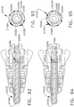
- FIGS. 9-14 illustrate portions of another lockable firing assembly 20300 that is prevented from being advanced distally unless an unspent surgical staple cartridge has been properly seated within the end effector channel 20400.
- FIG. 9 illustrates the threaded nut portion 20302 of the firing assembly 20300 that is threadably journaled on a rotary end effector drive shaft in the manner described herein. The rotary end effector drive shaft has been omitted for clarity in FIGS. 9-14 .
- a locking lug 20304 and an actuator lug 20306 protrude laterally from the threaded nut portion 20302.
- the firing assembly 20300 includes an upper firing body with a tissue cutting edge that may be similar to those disclosed herein.
- the channel 20400 is configured to operably and removably support a surgical staple cartridge therein.
- the channel 20400 includes a centrally disposed, longitudinal slot 20402 that is configured to operably support the rotary end effector drive shaft as well as to permit longitudinal travel of the threaded nut 20302 through the channel 20400.
- a first longitudinal ledge 20404 and a second longitudinal ledge 20406 are provided on each side of the longitudinal slot 20402.
- the ledges 20404, 20406 serve to define a longitudinal passage 20408 that permits passage of the lugs 20304 and 20306 therein when the firing assembly 20300 is distally fired through the channel 20400.
- the channel 20400 includes a longitudinal cavity 20410 for receiving the cartridge body therein. It will be understood that the cartridge body may be configured to be snappingly and removably retained within the cavity 20410.
- a locking notch 20412 is provided in the ledge 20404.
- the locking notch 20412 is sized to receive at least a portion of the locking lug 20304 therein when the firing assembly 20300 is in a first or beginning position prior to firing.
- a lock spring or biasing member 20414 is provided on the ledge 20406 and is configured to engage and bias the actuator lug 20306 in the locking direction "L". Such rotation of the actuator lug 20306 causes the locking lug 20304 to enter into the locking notch 20412. When in that position, the firing assembly 20300 cannot be advanced distally when the rotary end effector drive shaft is rotated in a firing direction.
- FIG. 12 illustrates the position of the threaded nut portion 20302 of the firing assembly 20300 when the firing assembly has been moved to a second or unlocked position.
- FIG. 13 illustrates what happens when a surgical staple cartridge is initially introduced into the channel 20400.
- the cartridge body has been omitted for clarity.
- the surgical staple cartridge includes a sled 20500.
- the sled 20500 is movable from the starting position located in the proximal end of the staple cartridge to an ending position within the cartridge.
- the sled 20500 includes a central sled body 20502 that has a collection of cam wedges 20504 formed therein.
- the sled 20500 includes four cam wedges 20504 with two cam wedges 20504 being located on each side of the central sled body 20502.
- Each cam wedge 20504 corresponds to a line of staple supporting drivers located in the cartridge 20500.
- the cam wedges 20504 sequentially drive the staple drivers in the corresponding line upward within the cartridge to thereby eject the staples into forming contact with the underside of the anvil.
- the sled 20500 is configured to contact the actuator lug 20306 when the cartridge is properly installed within the channel 20400 and the sled is in the starting position.
- a downwardly extending actuator member 20506 is formed on or otherwise attached to the sled 20500.
- the actuator member 20506 on the sled 20500 contacts the actuator lug 20306 and biases the firing assembly in the unlocking direction "UL" ( FIG. 13 ) to the position shown in FIG. 14 .
- the locking lug 20304 is out of the locking notch 20412 and the firing assembly 20300 can now be longitudinally advanced through the channel and the staple cartridge.
- FIGS. 15-17 illustrate portions of an end effector 20500 that is configured to cut and staple tissue.
- the end effector 20500 comprises an elongate channel 20510 that is configured to operably support a surgical staple cartridge 20600 therein.
- the end effector includes an anvil assembly 20700 that operably supports an anvil concentric drive member 20710 for operably driving a firing member 20720 through the end effector 20500.
- the anvil concentric drive member 20710 may, for example, be centrally disposed within the anvil frame 20712 and substantially extend the length thereof.
- the anvil concentric drive member 20710 in the illustrated embodiment comprises an anvil drive shaft that includes a distal bearing lug 20714 and a proximal bearing lug 20716.
- the distal bearing lug 20714 is rotatably housed in a distal bearing housing 20718 that is supported in a bearing pocket in the anvil frame 20712.
- the proximal bearing lug 20716 is rotatably supported in the anvil assembly 20700 by a floating bearing housing 20720 that is movably supported in a bearing pocket 20722 that is formed in the proximal anvil portion 20724. See FIG. 16 .
- the proximal and distal bearing housing arrangements may serve to prevent or at least minimize an occurrence of compressive forces on the anvil drive shaft 20710 which might otherwise cause the anvil drive shaft 20710 to buckle under high force conditions.
- the anvil drive shaft 20710 further includes a driven firing gear 20726, a proximal threaded or helix section 20728 and a distal threaded or helix section 20730.
- the proximal threaded section 20728 has a first length and the distal threaded section 20730 has a distal length that is greater than the first length.
- the pitch of the distal threaded section 20730 is greater than the pitch of the proximal threaded section 20728.
- the lead of the distal threaded section 20730 is greater than the lead of the proximal threaded section 20728.
- the lead of the distal threaded section 20730 may be approximately twice as large as the lead of the proximal threaded section 20728.
- a dead space 20731 may be provided between the proximal threaded section 20728 and the distal threaded section 20730.
- the anvil drive shaft 20710 may be fabricated in one piece from extruded gear stock.
- the anvil assembly 20700 includes an anvil cap 20740 that may be attached to the anvil frame 20712 by welding, snap features, etc.
- the anvil assembly 20700 includes a pair of anvil plates or staple forming plates 20742 that may contain various patterns of staple forming pockets on the bottom surfaces thereof that correspond to the staple arrangements in the surgical staple cartridge 20600 that is supported in the elongate channel 20510.
- the staple forming plates 20742 may be made of a metal or similar material and be welded to or otherwise attached to the anvil frame 20712. In other arrangements, a single anvil plate that has a slot therein to accommodate a firing member may also be employed. Such anvil plate or combination of plates may serve to improve the overall stiffness of the anvil assembly.
- the anvil plate(s) may be flat and have the staple forming pockets "coined" therein, for example.
- the surgical end effector 20500 includes a firing member 20800 that has a body portion 20802 that has a knife nut portion 20804 formed thereon or otherwise attached thereto.
- the knife nut portion 20804 is configured to be received on the anvil drive shaft 20710.
- a distal thread nodule 20806 and a proximal thread nodule 20808 that are configured to engage the proximal threaded section 20728 and the distal threaded section 20730 are formed in the knife nut portion 20804.
- the distal thread nodule 20806 is spaced from the proximal thread nodule 20808 relative to the length of the dead space 20731 such that when the knife nut portion 20804 spans across the dead space 20731, the distal thread nodule 20806 is in threaded engagement with the distal threaded section 20730 and the proximal thread nodule 20808 is in threaded engagement with the proximal threaded section 20728.
- anvil engaging tabs 20810 protrude laterally from opposite lateral portions of the knife nut 20804 and are each oriented to engage the corresponding staple forming plates 20742 that are attached to the anvil frame 20712.
- the firing member 20800 further includes a channel engaging tab 20820 that protrudes from each lateral side of the body portion 20800
- the firing member 20800 also includes a tissue cutting surface 20822.
- Rotation of the anvil drive shaft 20710 in a first rotary direction will result in the axial movement of the firing member 20800 from a first position to a second position.
- rotation of the anvil drive shaft 20710 in a second rotary direction will result in the axial retraction of the firing member 20800 from the second position back to the first position.
- the anvil drive shaft 20710 ultimately obtains rotary motion from a proximal drive shaft (not shown) that operably interfaces with a distal power shaft 20830.
- the distal power shaft 20830 has a distal drive gear 20832 that is configured for meshing engagement with the driven firing gear 20726 on the anvil drive shaft 20710 when the anvil assembly 20710 is in the closed position.
- the anvil drive shaft 20710 is said to be "separate and distinct" from the distal power shaft 20830. That is, at least in the illustrated arrangement for example, the anvil drive shaft 20710 is not coaxially aligned with the distal power shaft 20830 and does not form a part of the distal power shaft 20830. In addition, the anvil drive shaft 20710 is movable relative to the distal power shaft 20830, for example, when the anvil assembly 20700 is moved between open and closed positions.
- the proximal drive shaft may ultimately be rotated by a motor supported in a housing that is attached to a shaft assembly coupled to the surgical end effector 20500.
- the housing may comprise a handheld assembly or a portion of a robotically controlled system.
- the anvil assembly 20700 is closed by distally advancing a closure tube 20900.
- the closure tube 20900 includes an internally threaded closure nut 20902 that is configured for threaded engagement with a closure thread segment 20834 that is formed on the distal power shaft 20830.
- Initial rotation of the distal power shaft 20830 will drive the closure tube 20900 distally to cam the anvil assembly 20700 to the closed position.
- Rotation of the distal power shaft 20830 in an opposite direction will drive the closure tube 20900 in the proximal direction to permit the anvil assembly 20700 to move to an open position.
- the firing member body 20802 When in that position, the firing member body 20802 is out of alignment with the slot space and the tabs 20820 are out of alignment with the distal firing cavity 20518. When in that position, one of the tabs 20820 that protrude from the firing member 20800 is in alignment with one of the retention tabs 20512 and thus the firing member 20800 is prevented from being longitudinally advanced through the channel 20510.
- the firing member 20800 will pivot to that "locked" position when the anvil drive shaft 20710 is initially rotated and a surgical staple cartridge with a sled in a starting position has not been installed in the channel 20510.
- the sled will serve to contact or otherwise interface with the firing member 20800 to position and retain the firing member 20800 in alignment with the space 20514 between the retention tabs 20512. See FIG. 19 .
- continued rotation of the anvil drive shaft 20710 will drive the firing member 20800 distally through the channel 20510 as shown in FIG. 20 .
- Such arrangement will therefore, prevent the clinician from unwittingly actuating the anvil drive shaft 20710 to drive the firing member 20800 distally through the channel 20510 unless an unspent surgical staple cartridge that has a sled in a starting position has been installed in the channel.
- the detection of the sled in the correct location within an unspent staple cartridge that has been properly seated in the channel of a surgical cutting and stapling end effector may be determined electrically. For example, this may be accomplished with contacts on the sled that complete a circuit when the sled is in a starting position in a cartridge that has been properly seated in the channel. Upon firing, the circuit is opened and further firing is not permitted until the circuit is closed again.
- stapling assemblies for first grasping, clamping, stapling, and/or cutting tissue are well known in the art.
- Previous stapling assemblies such as those disclosed in U.S. Patent No. 5,865,361 , for example, have comprised a loading unit that is operably connected to a handle assembly.
- the disclosure of U.S. Patent No. 5,865,361, entitled SURGICAL STAPLING APPARATUS, which issued on February 2, 1999 is incorporated by reference in its entirety. While the handle assemblies of these previous stapling assemblies were configured for multiple uses, the loading units were configured for a single use.
- U.S. Patent Application Publication No. 2012/0286021 discloses an alternative stapling assembly comprising a first jaw including an anvil and a second jaw including a staple cartridge.
- the entire disclosure of U.S. Patent Application Publication No. 2012/0286021, entitled REPLACEABLE STAPLE CARTRIDGE, which published on November 15, 2012 is incorporated by reference herein.
- the second jaw of these stapling assemblies can be completely removed from the loading unit and then replaced with another second jaw, presumably after the previous second jaw has been spent.
- the entire second jaw of these stapling assemblies is replaced - not just a portion of the second jaw as disclosed in U.S. Patent No. 6,988,649, entitled SURGICAL STAPLING INSTRUMENT HAVING A SPENT CARTRIDGE LOCKOUT, which issued on January 24, 2006 , the entire disclosure of which is incorporated by reference herein.
- the stapling assembly disclosed in U.S. Patent Application Publication No. 2012/0286021 is defective.
- the stapling assembly disclosed in U.S. Patent Application Publication No. 2012/0286021 includes a cutting member which can be advanced distally eventhough a second jaw is not attached to the stapling assembly. As a result, the cutting member may be unintentionally exposed to the tissue of a patient.
- Various improvements to these stapling assemblies, among others, are discussed further below.
- a surgical instrument system 21000 comprises a handle 21010 and a stapling assembly, or loading unit, 21030 attached to a shaft 21020 of the handle 21010.
- the loading unit 21030 comprises a proximal end, or bayonet connector, 21032 configured to releasably attach the loading unit 21030 to the shaft 21020.
- the loading unit 21030 comprises an anvil 21040 and an attachable cartridge jaw 21050.
- the cartridge jaw 21050 once attached to the loading unit 21030, is pivotable between an open position ( FIG. 21 ) and a closed, or clamped, position.
- the handle 21010 comprises an actuator, or trigger, 21014 which is rotatable toward a pistol grip 21012 of the handle 21010 to drive a firing bar of the loading unit 21030 distally.
- the firing bar engages the cartridge jaw 21050 and moves the cartridge jaw 21050 into its closed position.
- the firing bar is advanced through the cartridge jaw 21050.
- the cartridge jaw 21050 comprises a plurality of staples removably stored therein which are ejected from the cartridge jaw 21050 as the firing bar is advanced distally through the cartridge jaw 21050. More particularly, as discussed in greater detail elsewhere herein, the firing bar enters into the cartridge jaw 21050 and pushes a sled stored in the cartridge jaw 21060 distally which, in turn, drives the staples out of the cartridge jaw 21050.
- the loading unit 21030 further comprises an articulation joint 21036 about which the anvil 21040 and the cartridge jaw 21050 can be articulated.
- the loading unit 21030 comprises an articulation driver configured to articulate the anvil 21040 and the cartridge jaw 21050 about the articulation joint 21036.
- the articulation driver is operably coupled with an articulation actuator 21016 which is rotatable to push or pull the articulation driver, depending on the direction in which the articulation actuator 21016 is rotated.
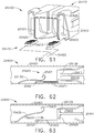
- FIGS. 23 and 24 An alternative surgical instrument system 21100 is illustrated in FIGS. 23 and 24 .
- the system 21100 comprises a handle 21110 and an attachable loading unit 21130. Similar to the above, the loading unit 21130 comprises an anvil jaw 21040 and a removably attached cartridge jaw 21050.
- the loading unit 21130 further comprises an articulation joint 21138 and a flex joint 21136 which are configured to permit the end effector to articulate relative to a shaft portion 21120 of the loading unit 21130.
- the shaft portion 21120 comprises a proximal connector 21122 configured to attach the loading unit 21130 to the handle 21110. Referring primarily to FIG.
- the proximal connector 21122 comprises rotatable inputs 21128 which are operably engageable with rotatable outputs 21118 of the handle 21110.
- Each rotatable input 21128 is part of a drive system which articulates the loading unit 21130 about the flex joint 21136 and/or articulation joint 21128, closes the cartridge jaw 21050, and/or fires the staples from the cartridge jaw 21050, for example.
- the handle 21110 comprises controls 21114 and 21116 which can be utilized to operate the drive systems of the loading unit 21130.
- the staple cartridge jaw 21050 further comprises clips 21056 configured to engage and grasp the attachment projections 21042.
- Each clip 21056 is positioned within a slot 21055 defined in the cartridge jaw 21050.
- the clips 21056 flex around the attachment projections 21042.
- the clips 21056 resiliently snap or return toward their unflexed configuration and hold the attachment projections 21042 in the recesses 21052.
- a loading unit 21130 comprises a system configured to detect whether or not a staple cartridge jaw 21150 is properly attached to an anvil jaw 21140 of the loading unit 21130, as described in greater detail below.
- the loading unit 21130 comprises an electrical circuit that is completed, or closed, when the staple cartridge jaw 21150 is properly attached to the loading unit 21130.
- the electrical circuit is in communication with a microprocessor, or controller, of the surgical instrument system.
- the controller is in the handle of the surgical instrument system; however, the controller can be in any suitable part of the surgical instrument system, such as the loading unit 21130, for example.
- the controller can be in a housing of a surgical instrument assembly that is attached to a robotic surgical system and/or in the robotic surgical system itself. In any event, the controller is in communication with an electric motor which drives the staple firing system of the surgical instrument system.
- the controller can prevent the electric motor from driving the staple firing system through a staple firing stroke.
- the controller can open a switch between a power source, such as a battery, for example, and the electric motor to prevent electrical power from being supplied to the electric motor.
- the controller can permit the electric motor to receive power from the battery and drive the staple firing system through a staple firing stroke when actuated by the user of the surgical instrument system.
- the controller can close the switch between the battery and the electric motor, for example.
- the clips 21056 are configured to hold the contacts 21159 of the staple cartridge jaw 21150 against the contacts 21146 extending around the attachment portions 21142.
- the clips 21056 are comprised of a conductive material and are in communication with the trace 21157.
- the clips 21056 are part of the electrical circuit in the staple cartridge 21150.
- the electrical circuit is broken, or opened, and the microprocessor can detect that a staple cartridge jaw 21150 is no longer attached to the loading unit 21130.
- the controller can determine that a staple cartridge jaw 21150 is improperly attached to the loading unit 21130 if only one of the contacts 21159 is engaged with its respective contact 21146.
- the electrical circuit would be in an open condition and, as a result, the microprocessor would treat an improperly assembled staple cartridge jaw 21150 as a missing cartridge jaw 21150 and prevent the electric motor from being actuated to perform the staple firing stroke.
- the surgical instrument system can include an indicator light and/or feedback system that communicates to the user of the surgical instrument system that the staple cartridge jaw detection circuit has not been closed. In response thereto, the user can investigate the condition and properly seat the staple cartridge jaw 21150 to close the detection circuit.
- the conductor 21157 extends laterally across the cartridge jaw 21150.
- the firing member can transect and/or break the conductor 21157 and open the jaw detection circuit.
- the controller can permit the electric motor to be operated to advance the firing member distally until the firing member is retracted back to its unfired position.
- the controller can then prevent the re-operation of the electric motor until an unspent cartridge jaw 21150 is properly attached to the loading unit 21130.
- the electrical circuit of the loading unit 21130 can serve as a missing cartridge lockout, an improperly attached cartridge lockout, and a spent cartridge lockout.
- the sled 21170 can comprise a conductive portion which electrically connects the lateral jaw contacts 21159 and/or the electrically conductive clips 21056 when the sled 21170 is in its unfired position.
- the sled 21170 comprises a conductor and/or trace extending from one lateral side of the sled 21170 to the other.
- the conductive portion of the sled 21170 is no longer in electrical communication with the contacts 21159 and/or clips 21056 and the jaw detection circuit is opened.
- the jaw assembly also comprises the conductor 21157
- the conductor 21157 can be cut or broken to open the jaw detection circuit as described above.
- the sled 21170 can be displaced from the jaw detection circuit at the same time that the conductor 21157 is cut or broken, for example.
- the conductive sled 21170 can provide a spent cartridge lockout.
- the compliant contacts 21257 are configured to engage an anvil jaw 21240 of the loading unit 21230 when the staple cartridge jaw 21250 is assembled to the loading unit 21250. More specifically, the compliant contacts 21257 engage a conductive pathway 21247 defined in the anvil jaw 21240 which electrically connects the compliant contacts 21257 and, at such point, the electrical circuit has been closed. The compliant contacts 21257 remain constantly engaged with the conductive pathway 21247, i.e., when the cartridge jaw 21250 is in an open position, when the cartridge jaw 21250 is in a closed position, and when the cartridge jaw 21250 is moved between its open and closed positions.
- the compliant contacts 21257 can comprise springs configured to bias the staple cartridge jaw 21250 into an open position. When the staple cartridge jaw 21250 is moved into its closed position, the compliant contacts 21257 are compressed between the staple cartridge jaw 21250 and the anvil 21240. The compliant contacts 21257, along with the other portions of the electrical jaw detection circuit, are electrically insulated from the metal, or conductive, portions of the stapling assembly so as to maintain the integrity of the jaw detection circuit and prevent the jaw detection circuit from shorting out.
- the lockout members 21172 can block the distal advancement of the firing member 21160, as discussed above, the firing member 21160 may be able to push through and slide between the lockout members 21172 in certain instances.
- one or both of the lockout members 21172 can comprise a latch or hook extending inwardly toward the firing member 21160.
- the lockout members 21172 are biased inwardly after the sled 21170 has been advanced distally, the latches or hooks can engage apertures defined in the firing member 21160 when the firing member 21160 is retracted back into its unfired position. Once the latches or hooks are positioned in the firing member apertures, they can prevent the firing member 21160 from being advanced distally through the already spent cartridge. At such point, the staple cartridge would have to be replaced to unlock the firing member 21160.
- a stapling assembly 21530 comprises an attachable staple cartridge jaw 21550 including a cartridge body 21551 and, in addition, a pivotable anvil jaw 21540.
- the stapling assembly 21530 further comprises a firing member, such as firing member 21160, for example, which is movable distally to engage the anvil jaw 21540 and move the anvil jaw 21540 into a closed position.
- the firing member 21160 comprises a first camming member 21162 configured to engage the cartridge jaw 21550 and a second camming member 21164 configured to engage the anvil jaw 21540 and move the anvil jaw 21540 toward the cartridge jaw 21550.
- the stapling assembly 21530 further comprises a mechanical lockout 21572.
- the lockout 21572 is mounted to a frame of the stapling assembly 21530 at a frame pivot 21232.
- the lockout 21572 extends distally and is supported by a frame pin 21533.
- the lockout 21572 comprises a metal wire; however, the lockout 21572 can be comprised of any suitable material.
- the lockout 21572 further comprises an elongated recess track 21576 defined therein which is configured to receive a lockout pin 21166 extending from the firing member 21160. Referring primarily to FIG. 35 , the elongated recess track 21276 constrains or limits the longitudinal displacement of the firing member 21160 when the lockout 21572 is in its locked position.
- the recess track 21576 is configured to permit the firing member 21160 to be advanced distally to move the anvil jaw 21540 between its open and closed positions but prevent the firing member 21160 from being advanced distally to perform a firing stroke unless the lockout 21572 is moved into its unlocked position, as discussed below.
- the lockout pin 21166 can engage the lockout 21572 and flex the lockout 21572 downwardly to permit the firing member 21160 to return to its unfired position.
- the sled 21270 is not retracted with the firing member 21160 and, as a result, cannot re-unlock the lockout 21572 even though the firing member 21160 has been retracted.
- the lockout 21572 can serve as a missing cartridge lockout and a spent cartridge lockout.
- a stapling assembly 21330 comprises an attachable staple cartridge jaw 21350 including a cartridge body 21351and, in addition, an anvil jaw 21340.
- the stapling assembly 21330 further comprises a firing member, such as firing member 21160, for example, which is movable distally to engage the anvil jaw 21340 and the cartridge jaw 21350.
- the firing member 21160 comprises a first camming member 21162 configured to engage the cartridge jaw 21350 and a second camming member 21164 configured to engage the anvil jaw 21340 which close the jaws 21340 and 21350 when the firing member 21160 is advanced distally.
- the stapling assembly 21330 further comprises a mechanical lockout 21372.
- the lockout 21372 is mounted to a frame of the stapling assembly 21330 at a frame pivot 21232.
- the lockout 21372 extends distally and is constrained by a frame pin 21333.
- the lockout 21372 comprises a metal wire; however, the lockout 21372 can be comprised of any suitable material.
- the lockout 21372 further comprises an elongate recess track 21376 defined therein which is configured to receive the lockout pin 21166 extending from the firing member 21160. Referring primarily to FIG. 39 , the elongate recess track 21376 constrains or limits the longitudinal displacement of the firing member 21160 when the lockout 21372 is in its locked position. More specifically, the recess track 21376 is configured to permit the firing member 21160 to be advanced distally to close the stapling assembly 21330 but prevent the firing member 21160 from being advanced distally to perform a firing stroke.
- the sled 21370 of the cartridge jaw 21350 contacts distal arms 21374 of the lockout 21372 and deflects the lockout 21372 upwardly into an unlocked position.
- the lockout 21372 has been displaced above the lockout pin 21166 of the firing member 21160 and, as a result, the firing member 21160 can be advanced distally to perform a staple firing stroke, as illustrated in FIG. 41 .
- the firing member 21160 pushes the sled 21370 distally out from under the lockout arms 21374 and the lockout 21372 can return back to its unflexed, or locked, configuration.
- the arms 21374 of the lockout 21372 are laterally spaced apart on opposite sides of the longitudinal slot 21359 such that the firing member 21160 can slide between the arms 21374. In such instances, the arms are not transected by the firing member 21160.
- a first loading unit can be used which is configured to apply a 30 mm staple line
- a second loading unit can be used which is configured to apply a 45 mm staple line
- a third loading unit can be used which is configured to apply a 60 mm staple line, for example.
- each of these loading units comprises a replaceable cartridge jaw
- a clinician may attempt to attach a 60 mm staple cartridge jaw to a loading unit configured to apply a 30 mm staple line.
- the stapling assemblies and/or loading units disclosed herein can include means for preventing the wrong staple cartridge jaw from being attached thereto, as discussed in greater detail below.
- the recesses 21052 defined in the cartridge jaw 21250 are configured to closely receive the attachment projections 21142 of the loading unit 21130 such that there is a snug fit therebetween.
- the attachment projections 21242' ( FIG. 45 ) of a second loading unit 21130' are smaller than the attachment projections 21142 and, correspondingly, the recesses of a second cartridge jaw for use with the second loading unit 21130' are smaller than the recesses 21052.
- the recesses of the second cartridge jaw are too small to receive the attachment projections 21142 of the loading unit 21130 and, as a result, the second cartridge jaw cannot be attached to the loading unit 21130.
- the recesses 21052 of the cartridge jaw 21250 are larger than the attachment projections 21242' of the second loading unit 21130' such that the clips 21056 of the cartridge jaw 21250 cannot hold the attachment projections 21242' in the recesses 21052 and, as a result, cannot hold the cartridge jaw 21250 to the loading unit 21130'. In such instances, the interconnection between the cartridge jaw 21250 and the loading unit 21130' would be too loose for the cartridge jaw 21250 to be used with the loading unit 21130'.
- the attachment projections of a loading unit, the recesses of a staple cartridge jaw, and the spring clips holding the staple cartridge jaw to the loading unit have the same configuration on both sides of the stapling assembly.
- the attachment projection, the recess, and/or the spring clip on one side of the stapling assembly is different than the attachment projection, the recess, and/or the spring clip on the other side of the stapling assembly.
- a large attachment projection, recess, and spring clip are disposed on one side of the stapling assembly while a smaller attachment projection, recess, and spring clip are disposed on the other side.
- Such arrangements can increase the permutations available to prevent an incorrect staple cartridge jaw from being attached to a loading unit.
- the attachment projections of a loading unit, the recesses of a staple cartridge jaw, and the spring clips are aligned with respect to a common lateral axis.
- the attachment projection, the recess, and/or the spring clip on one side of the stapling assembly are not aligned with the attachment projection, the recess, and/or the spring clip on the other side. Stated another way, one side is offset from the other.
- Such arrangements can also increase the permutations available to prevent an incorrect staple cartridge jaw from being attached to a loading unit.
- each loading unit of the kit can be configured such that only a cartridge jaw intended to be used with the loading unit can be properly attached to the loading unit.
- the staple cartridge jaw 21050 comprises a proximal shoulder 21058 which is positioned in close proximity to the frame of the loading unit 21030 when the cartridge jaw 21050 is attached to the loading unit 21030. Owing to the snug fit between the projections 21042, the recesses 21052, and the clips 21056, the cartridge jaw 21050 is held in position such that the shoulder 21058 of the cartridge jaw 21050 does not interfere with the distal progression of the firing member 21160, for example. More particularly, the shoulder 21058 does not interfere with the first camming member 21162 of the firing member 21160.
- a staple cartridge jaw 21450 is an incorrect staple cartridge jaw for use with the loading unit 21030. Eventhough the staple cartridge jaw 21450 has been attached to the loading unit 21030, the proximal shoulder 21458 prevents the firing member 21060 from being advanced distally.
- the proximal shoulder of a staple cartridge jaw can comprise a sharp or abrupt corner.
- the proximal shoulder does not comprise a chamfer or lead-in, for example.
- a proximal shoulder of a staple cartridge jaw can be configured to block the distal advancement of a staple firing member if the tissue clamped between the staple cartridge jaw and an opposing anvil jaw is too thick.
- the staple cartridge jaw would not close completely and the proximal shoulder of the staple cartridge jaw would be positioned in front of the staple firing member.
- Such an arrangement would comprise a tissue thickness lockout; however, such an arrangement could also serve as a tissue clamping lockout in the event that the staple cartridge jaw had not yet been moved into its clamped position.
- an electronic or software lockout of a surgical instrument system can be utilized to prevent a firing drive from performing a staple firing stroke in the event that an incorrect staple cartridge jaw is attached to the surgical instrument system.
- a portion of a jaw detection circuit can extend through a staple cartridge jaw and, in at least one instance, a controller of the surgical instrument system can be configured to evaluate the portion of the jaw detection circuit extending through the staple cartridge jaw to determine whether the staple cartridge attached to the surgical instrument system jaw is an appropriate staple cartridge jaw for use with the surgical instrument system.
- the clips 21056 of a first staple cartridge jaw have detectably different electrical properties, such as resistance or impedance, for example, than the clips 21056 of a second staple cartridge jaw.
- a cartridge jaw removal tool 21090 can be used to detach a cartridge jaw from a loading unit.
- U.S. Patent Application Publication No. 2012/0286021 discusses a cartridge removal tool in greater detail.
- the system 25100 comprises a firing member 25110, a staple cartridge assembly 25120, and an anvil jaw 25130.
- the firing member 25110 comprises a distally-presented cutting portion 25111 configured to cut tissue when advanced through an end effector portion of the surgical instrument system 25100.
- the firing member 25110 is configured to deploy a plurality of staples from the staple cartridge assembly 25120 toward the anvil jaw 25130 by advancing a sled 25121 longitudinally through the staple cartridge assembly 25120.
- the sled 25121 is movable from a proximal unfired position to a distal fully-fired position during a staple firing stroke.
- the firing member 25110 is retracted.
- the sled 25121 does not retract with the firing member 25110.
- embodiments are envisioned in which the sled 25121 is at least partially retracted.
- the surgical instrument system 25100 further comprises a lockout member 25140.
- the lockout member 25140 is configured to prevent the firing member 25110 from being advanced through the staple firing stroke when a cartridge is not present in the surgical instrument system 25100 or a spent, or partially spent, cartridge is present in the surgical instrument system 25100.
- the lockout member 25140 comprises a proximal portion 25141 pivotably mounted to a spine pin 25101 of a frame portion of the system 25100.
- the lockout member 25140 further comprises a lock face, or shoulder, 25142 configured to catch the firing member 25110, and a deflectable portion 25143.
- the lockout member 25140 is movable, or deflectable, between a locked position ( FIG. 50 ) and an unlocked position ( FIG.
- the lockout member 25140 is spring-biased into the locked position when a staple cartridge assembly is not installed within the system 25100, as discussed in greater detail below.
- the lockout member 25140 is also spring-biased into the locked position when a spent, or partially spent, staple cartridge assembly is installed within the system 25100, as also discussed in greater detail below.
- a firing member pin 25113 mounted on the firing member 25110 is configured to abut the lock face 25142 of the lockout member 25140 which prevents the firing member 25110 from being advanced distally.
- an unspent, ready-to-fire staple cartridge assembly must be properly installed within in the system 25100. More specifically, the sled 25121 of an unspent, ready-to-fire staple cartridge assembly is in its proximal unfired position and, when such a staple cartridge assembly is installed into the system 25100, the sled 25121 deflects, or bends, the deflectable portion 25143 downwardly into its unlocked positon.
- the firing member pin 25113 is clear to advance beyond the lock face 25142 thus permitting the firing member 25110 to be advanced distally to deploy staples and cut tissue during a firing stroke.
- the system 25200 comprises another type of a missing cartridge and spent cartridge lockout arrangement.
- the system 25200 comprises a firing member 25210 and a staple cartridge assembly 25220.
- the firing member 25210 comprises a distally-presented cutting portion 25211 configured to cut tissue when advanced through the system 25200.
- the firing member is configured to deploy a plurality of staples from the staple cartridge assembly 25220 by advancing a sled 25221 longitudinally through the staple cartridge assembly 25220.
- the sled 25221 is movable from a proximal unfired position to a distal fully-fired position during a staple firing stroke.
- the sled 25221 does not retract with the firing member 25210; however, embodiments are envisioned in which the sled 25221 is at least partially retracted.
- the surgical instrument system 25200 further comprises a lockout member 25240.
- the lockout member 25240 is configured to prevent the firing member 25210 from being advanced through its staple firing stroke when a cartridge is not present within the system 25200 or a spent, or partially spent, cartridge is present within the system 25200.
- the lockout member 25240 comprises a first, or proximal, portion 25241 rotatably mounted to a first spine pin 25201 of the system 25200.
- the spine pin 25201 may extend from a shaft frame, or spine, of the system 25200, for example.
- the lockout member 25240 further comprises a second portion 25242, a third, or catch, portion 25243, and a fourth, or distal, portion 25245.
- the lockout member 25240 is movable between a locked position ( FIGS.
- a firing member pin 25213 mounted on the firing member 25210 is configured to abut a lock face, or shoulder, 25244 of the lockout member 25240.
- a lock face 25244 distal advancement of the firing member 25210 is blocked beyond this position.
- an unspent, ready-to-fire staple cartridge assembly must be installed within the system 25200.
- An unspent, ready-to-fire staple cartridge assembly comprises a sled 25221 in a proximal unfired position.
- the sled 25221 comprises a magnet 25226 oriented with one of its poles "P1" facing the distal portion 25245 of the lockout member 25240 and another pole “P2" facing away from the distal portion 25245 of the lockout member 25240.
- the distal portion 25245 of the lockout member 25240 comprises a magnet 25246 disposed thereon.
- the magnet 25246 is orientated with a pole "P1" facing the like pole "P1" of the sled magnet 25226 and another pole “P2” facing away from the sled magnet 25226.
- the pole P1 of the magnet 25226 and the pole P1 of the magnet 25246 repel each other.
- This relationship creates a levitational effect when the sled 25221 is in its proximal unfired position ( FIG. 53 ) which pushes, or repels, the lockout member 25240 upward into its unlocked position, lifting the lock face 25244 away from the pin 25213 of the firing member 25210 to permit the pin 25213 to advance beyond the lock face 25142.
- the firing member 25210 can then be advanced distally to deploy staples and cut tissue during a firing stroke.
- the pin 25213 When the firing member 25210 is retracted after its firing stroke, the pin 25213 is configured to contact an angled face of the distal portion 25245 to push the distal portion 25245 and, thus, the lockout member 25240 toward its unlocked position permitting the pin 25213 to pass the lock face 25244 when returning to a home position. Once the pin 25213 passes the lock face 25244, the lockout member 25240 springs back, or returns, to its locked position to prevent to prevent the firing stroke from being repeated with a spent, or partially spent, staple cartridge installed within the system 25100.
- the lockout member 25240 is configured to permit the firing member 25210 to move within a distance "y" to permit the clamping and unclamping of the jaws when the firing member 25210 is relied on for the clamping and unclamping functions.
- the pin 25213 and, thus, the firing member 25210 can be moved proximally and distally within the catch portion 25243 of the lockout member 25240 even though a staple cartridge is missing from and/or a spent staple cartridge is positioned within the system 25100.
- FIGS. 55-60 Another surgical instrument system 25300 is depicted in FIGS. 55-60 .
- the system 25300 comprises another type of lockout arrangement where the system 25300 is configured to be locked out when a cartridge is not installed within the system 25300.
- the system is further configured to be locked out when a spent, or partially spent, cartridge is installed within the system 25300.
- the system 25300 comprises a firing member 25310 and a staple cartridge assembly 25320.
- the firing member 25310 comprises a distally-presented cutting portion 25311 configured to cut tissue when advanced through the system 25300.
- the firing member 25310 is configured to deploy a plurality of staples from the staple cartridge assembly 25320 by advancing a sled 25330 ( FIG. 56 ) longitudinally through the staple cartridge assembly 25320.
- the sled 25330 is movable between a proximal unfired position to a distal fully-fired position during a firing stroke. In various instances, the sled 25230 does not retract with the firing member 25310; however, embodiments are envisioned in which the sled 25230 is at least partially retracted.
- the surgical instrument system 25300 further comprises a lockout member 25340.
- the lockout member 25340 is configured to prevent the firing member 25310 from being advanced through a staple firing stroke when a cartridge is not present within the system 25300 or a spent, or partially spent, cartridge is present within the system 25300.
- the lockout member 25340 is similar to the lockout members 25140, 25240 in many respects. Referring to FIGS. 58-60 , the lockout member 25340 comprises a first, or proximal, portion 25341 rotatably mounted to a first spine pin 25301 of the system 25300. Alternatively, the proximal portion 25341 can be fixedly mounted to the spine 25301 of the system 25300.
- the lockout member 25340 further comprises a second portion 25342, a third, or catch, portion 25343, and a fourth, or distal, portion 25345.
- the lockout member 25340 is movable between a locked position ( FIGS. 58 and 60 ) and an unlocked position ( FIG. 59 ).
- the lockout member 25340 is spring-biased into its locked position when a staple cartridge assembly is not installed within the system 25300.
- the lockout member 25340 is also biased into its locked position when a spent, or partially spent, staple cartridge assembly is installed within the system 25300.
- the staple cartridge assembly 25320 comprises a sled 25330 and plurality of drivers 25328 configured to eject a staple upon being driven by the ramps 25330A, 25330B, 25330C, and 25330D of the sled 25330 during a staple firing stroke.
- the staple cartridge assembly 25320 further comprises a control member movable between an unspent position and a spent position by the sled 25330 when the sled 25330 is advanced distally during its staple firing stroke.
- the control member is in its unspent position when a staple cartridge 25320 is loaded into the surgical instrument system 25300 and is configured to move the lockout member 25340 from its locked position to its unlocked position when the unspent staple cartridge assembly 25320 is loaded into the surgical instrument system 25300.
- FIGS. 55 and 57 A first configuration of a proximal driver 25325 is illustrated in FIGS. 55 and 57 .
- the proximal driver 25325 comprises a driver wedge portion 25326 and a magnetic portion 25327.
- the driver wedge portion 25326 is positioned within a sled notch 25331 and the magnetic portion 25327 is in close enough proximity to the distal portion 25327 to attract the distal portion 25327 to move, or lift, the lockout member 25340 into its unlocked position.
- a proximal driver 25325' comprises a driver wedge portion 25326' and a magnetic portion 25327'.
- the wedge portion 25326' of the proximal driver 25325' is positioned on the side of the proximal driver 25325'.
- the driver wedge portion 25326' is positioned within the sled notch 25331 and the magnetic portion 25327' is in close enough proximity to the distal portion 25327' to attract the distal portion 25327' to move the lockout member 25340 into its unlocked position.
- the magnetic portion 25327' is configured to retain the lockout member 25340 in its unlocked position.
- the sled 25330 drives the proximal driver 25325' so that the driver wedge portion 25326' is driven out of the sled notch 25331.
- a datum "D" is defined as a top surface of the sled 25330 and, when the bottom of the wedge portion 25326' is aligned with or above the datum D, the magnetic relationship between the distal portion 25345 and the magnetic portion 25327' is insufficient to hold the lockout member 25340 in its unlocked position thus releasing the lockout member 25340.
- the system 25300 is prevented from re-firing the same cartridge assembly 25320.
- the lockout pin 25312 rides underneath the distal portion to move the lockout member 25340 temporarily out of the way until the lockout pin 25312 reaches the catch portion 25343.
- the lockout member 25340 springs back, or returns, to its locked position.
- the magnetic portion 25327' does not pull the lockout member 25340 into its unlocked position.
- the proximal driver 25325' may engage the staple cartridge assembly 25320 in a press-fit manner when the proximal driver 25325' is moved into its spent position by the sled 25330 to prevent the proximal driver 25325' from falling toward its unspent position. Such an arrangement may prevent the lockout member 25340 from being falsely unlocked. In addition to a spent cartridge assembly, not having a cartridge installed within the system 25300 urges the lockout member into its locked position. The mere absence of a proximal driver altogether prevents the lockout member 25340 from moving to its unlocked position.
- control members 25325, 25325' are driven by the sled 25330 and can be referred to as drivers; however, they do not drive staples. In this way, the control members 25325, 25325' comprise "false" drivers. That said, it is contemplated that the proximal most staple driver of a staple cartridge assembly could be used as a control member.
- FIGS. 61-63 Another surgical instrument system is depicted in FIGS. 61-63 .
- the system 25400 comprises a staple cartridge assembly 25410, a lockout circuit system 25420, and a lockout member 25430.
- the lockout member 25440 is fixedly attached to a spine portion 25401 of the system 25400.
- the lockout member 25430 further comprises a spring member, for example, and is biased toward its locked position ( FIG. 63 ).
- a hook portion 25431 of the lockout member 25430 is configured to catch a firing member in the event that the surgical instrument or clinician tries to advance the firing member beyond the lockout member 25440 without an unspent staple cartridge assembly installed within the system 25400.
- an electromagnet 25421 is employed.
- the electromagnet 25421 is disposed on the spine portion 25401 of the system 25400 but may be disposed at any suitable location within the system 25400. Conductors are positioned within the system 25400 along the spine portion 25401, for example, to power the electromagnet 25421.
- the lockout circuit system 25420 which encompasses the electromagnet 25421 and its power source extends through the staple cartridge assembly 25410. As discussed below, when the circuit 25420 is complete, or closed, the electromagnet 25421 is powered. When the circuit is not complete, or open, the electromagnet 25421 is not powered. As also discussed below, the presence of a spent, or partially-spent, cartridge in the system 25400 is a scenario where the circuit 25420 is open. The absence of a cartridge in the system 25400 is another scenario where the circuit 25420 is open.
- the lockout circuit system 25420 comprises conductors 25422 extending from the electromagnet 25421 to a pair of electrical contacts 25423 positioned within the system 25400.
- the electrical contacts 25423 are positioned within a jaw of the system 25400 such as a channel portion which receives the staple cartridge assembly 25410, for example.
- the staple cartridge assembly 25410 further comprises conductor legs 25425 configured to engage the contacts 25423 when the staple cartridge assembly 25410 is fully seated in the channel portion of the jaw.
- the conductor legs 25425 are part of an electrical trace 25424 defined within the staple cartridge assembly 25410.
- the conductor legs 25425 are disposed on a proximal face 25412 of the cartridge assembly 25410.
- a severable portion 25426 of the electrical trace 25424 which extends across a slot 25411 of the staple cartridge assembly 25410.
- a cutting edge of a firing member is configured to sever, or incise, the severable portion 25426 during a staple firing stroke of the firing member.
- the severable portion 25426 When a cartridge assembly is installed and is unspent, further to the above, the severable portion 25426 is not severed and the lockout circuit 25420 is complete, or closed.
- the lockout circuit 25420 When the lockout circuit 25420 is complete ( FIG. 62 ), the electromagnet 25421 receives power urging the lockout member 25430 to its unlocked position permitting the firing member to pass thereby.
- the surgical instrument detects an incomplete circuit.
- An incomplete, or open, circuit indicates that the staple cartridge assembly 25410 is in a false configuration. This may be due to having a spent, or partially spent, cartridge installed or to not having a cartridge installed within the system 25400.
- the circuit 25420 When the circuit 25420 is incomplete ( FIG. 63 ), for example, in a false configuration, the electromagnet 25421 loses power and releases the lockout member 25430 to its locked position ( FIG. 63 ).
- the lockout circuit 25420 When the spent staple cartridge assembly 25410 is removed from the surgical instrument system 25400, the lockout circuit 25420 remains in an open state and the electromagnet 25421 remains unpowered. When an unspent staple cartridge assembly 25410 is fully seated in the system 25400, the lockout circuit 25420 is once again closed and the electromagnet 25421 is repowered to unlock the lockout member 25430. Notably, if a staple cartridge assembly 25410 is not fully seated in the system 25400, the legs 25425 will not be engaged with the contacts 25423 and the lockout circuit 25420 will remain in an open, unpowered state.
- FIGS. 64 and 65 Another surgical instrument system 25500 is depicted in FIGS. 64 and 65 .
- the system 25500 comprises a staple cartridge 25501 comprising a sled 25510 movable between an unfired position and a fired position.
- a firing member 25503 is configured to move the sled 25510 from its the unfired position to its fired position to deploy a plurality of staples (not shown) stored within the cartridge 25501 via ramps 25511.
- the system 25500 further comprises a circuit 25520 configured to indicate to the surgical instrument and/or the user of the system 25500 whether the cartridge installed within the system 25500 is spent, or partially spent, or whether the cartridge installed within the system 25500 is unspent and ready-to-fire.
- the sled 25510 When the sled 25510 is in its unfired position, the sled 25510 completes the circuit 25520 and when the sled 25510 is in its fired, or partially-fired, position, the sled 25510 does not complete the circuit 25520 and the circuit 25520 is open.
- the lockout circuit 25520 comprises a pair of conductors 25521 in electrical communication with a surgical instrument handle, for example, and a pair of electrical contacts 25522 positioned within a jaw portion of the surgical instrument system 25500 configured to support the staple cartridge 25501.
- the electrical contacts 25522 are positioned such that corresponding pads, or contacts, 25523 disposed on a proximal face 25512 of the sled 25510 contact the electrical contacts 25522 when the staple cartridge 25501 is fully seated in the system 25500 and the sled 25510 is in its unfired position ( FIG. 65 ).
- a tether portion, or conductor, 25524 connects, or electrically couples, the contacts 25523 and is attached to a proximal middle face 25513 of the sled 25510.
- the contacts 25522 extend to a bottom face of the sled in addition to the proximal face 25512.
- the lockout circuit 25520 is in signal communication with a controller of the surgical instrument system 255500 which supplies power to an electric motor of the firing drive when the lockout circuit 25520 is in a closed state and prevents power from being supplied to the electric motor when the lockout circuit 25520 is open.
- a firing member lockout arrangement of a system 25600 is depicted in FIGS. 66-70 .
- the system 25600 comprises a firing member 25610, a lockout 25620, and a shaft spine 25601.
- the shaft spine 25601 houses the lockout 25620 and the firing member 25610.
- the firing member 25610 comprises a distally-presented cutting edge 25611 configured to incise tissue during a staple firing stroke of the firing member 25610.
- the lockout 25620 is configured to catch the firing member 25610 when the lockout 25620 is activated and permit the firing member 25610 to pass thereby. Further to the above, the lockout 25620 can be activated by a controller of the system 25600 when an unspent staple cartridge is not positioned in the system 25600.
- the lockout 25620 comprises a solenoid 25621 and a mechanical linkage comprising a first link 25623 and a second link 25624.
- the links 25623, 25624 are attached at a pivot 25622.
- the solenoid 25621 is positioned within the spine 25601 such that the solenoid 25621 can apply a force to the linkage near the pivot 25622.
- the lockout 25620 is illustrated in its biased, locked position in FIGS. 66 and 67 .
- the lockout 25620 further comprises a lock body, or cam plate, 25625 pivotably coupled with an end of the second link 25624.
- the cam plate 25625 is biased into a knife band window 25612 to catch the firing member 25610 when the solenoid 25621 is in its unactuated configuration as illustrated in FIGS. 66 and 67 .
- multiple windows are provided in the firing member 25610.
- Another window such as the window 25614, may comprise another proximal surface.
- the window 25614 may act as an intermediate lockout to lock the firing member 25610 in the midst of an operation.
- An event such as knife binding, for example, may trigger the solenoid 25621 to release the lockout 25620 into its locked position to prevent further actuation of the firing member 25610.
- distal surfaces of the windows in the firing member 25610 may be configured such that when the firing member 25610 is retracted proximally, the cam plate 25625 may glide over the distal surfaces to prevent the locking of the firing member 25610 as the firing member 25610 is moved proximally. In other instances, locking the firing member 25610 as it moves proximally may be desirable.
- a lockout can be configured to permit movement in one direction but prevent movement in another direction. For example, slight retraction of the firing member 25610 may be desirable when the distal movement of the firing member 25610 has been locked out. When retracted proximally in such instances, the tissue in the area that caused the firing member 25610 to bind up may naturally decompress and, after a defined time period of waiting for the tissue to decompress, the solenoid 25621 may be activated to move the lockout 25620 into its unlocked position ( FIGS. 68 and 69 ) thus permitting the firing member 25610 to be advanced distally again.
- FIGS. 68-70 illustrate the lockout 25620 in its unlocked position.
- the solenoid 25621 moves the mechanical linkage into a collinear configuration to slide, or urge, the cam plate 25625 out of the window 25612 to unlock the firing member 25610.
- Slider supports 25603 are provided within the spine 25601 to guide the cam plate 25625 as the solenoid 25621 moves the mechanical linkage. The slider supports 25603, in at least one instance, control the movement of the cam plate 25625 to a linear path, for example.
- a lockout configured to prevent a firing member from being advanced distally in certain instances.
- the lockout is more than adequate to block the distal advancement of the firing member.
- a primary lockout and a secondary lockout can block the distal advancement of the firing member.
- the secondary lockout can be actuated as a result of the primary lockout being actuated.
- the primary lockout can block the distal advancement of the firing member because a staple cartridge jaw is missing from the loading unit, the staple cartridge jaw is improperly attached to the loading unit, and/or the staple cartridge jaw has previously been at least partially fired and, when the distal displacement of the firing member is impeded by the primary lockout, the secondary lockout can be actuated to assist the primary lockout in blocking the distal advancement of the firing member.
- a loading unit comprises a shaft 21730 and a firing member system extending through the shaft 21730.
- the firing member system comprises a first, or proximal, firing member 21760 and a second, or distal, firing member 21762.
- the proximal firing member 21760 is pushed distally by an electric motor and/or hand crank, for example.
- the distal firing member 21762 is pushed distally by the proximal firing member 21760.
- the firing member system further comprises a lockout 21780 positioned intermediate the proximal firing member 21760 and the distal firing member 21762.
- the lockout 21780 is configured to transmit a firing force from the proximal firing member 21760 to the distal firing member 21762 during a staple firing stroke. In the event that the force transmitted through the lockout 21780 exceeds the firing force expected during the staple firing stroke, and/or exceeds a predetermined threshold force, the lockout 21780 moves into a locked configuration as illustrated in FIG. 83 and as described in greater detail further below.
- the lockout 21780 comprises lock arms 21782 pivotably mounted to the proximal firing member 21760 at a pivot 21784.
- the lock arms 21782 are configured to abut drive surfaces 21768 defined on the proximal end of the firing member 21762 and push the firing member 21762 distally.
- the drive surfaces 21768 form a conical surface, for example.
- the lockout 21780 further comprises a biasing member, or spring, 21785 configured to bias the lockout arms 21782 inwardly toward an unlocked configuration, as illustrated in FIG. 82 , against the drive surfaces 21768.
- Each lock arm 21782 comprises a pin 21783 extending therefrom which is configured to mount an end of the spring 21785 thereto.
- the lock arms 21782 slide relative to the drive surfaces 21768 and splay, or rotate, outwardly into engagement with the shaft 21730.
- the shaft 21730 comprises a rack, or racks, of teeth 21781 defined therein which are engaged by the lock arms 21782 and prevent the proximal firing member 21760 from being advanced distally.
- the spring 21785 is resiliently stretched when the lock arms 21782 are displaced outwardly.
- the stiffness of the spring 21785 is selected such that the spring 21785 can hold the lock arms 21782 in their unlocked configuration against the drive surfaces 21768 when the force transmitted from the proximal firing member 21760 to the distal firing member 21762 is below the threshold force yet permit the lock arms 21782 to displace outwardly when the force transmitted from the proximal firing member 21760 to the distal firing member 21762 exceeds the threshold force.
- the force transmitted between the proximal firing member 21760 and the distal firing member 21762 is below the threshold force when the firing system is firing the staples from a staple cartridge and above the threshold force when the distal firing member 21760 is blocked by a missing cartridge and/or spent cartridge lockout, for example.
- the lockout 21780 is deployed in response to another lockout blocking the advancement of the staple firing system.
- the lockout 21780 can comprise a secondary lockout which co-operates with a primary lockout to block the advancement of the staple firing system.
- the lockout 21780 can provide overload protection to the staple firing system.
- the staple firing system can become jammed during a firing stroke and the lockout 21780 can deploy to stop the staple firing stroke.
- the lockout 21780 can transfer the firing force, or at least a portion of the firing force, to the shaft 21730 instead of the staple cartridge.
- the lockout 21780 can prevent the firing system and/or staple cartridge from being damaged, or at least further damaged.
- the lockout 21780 is deployed in response to a condition of the stapling assembly other than a predefined lockout.
- the teeth racks 21781 are the same length as, or longer than, the firing stroke of the staple firing system such that the lockout 21780 can engage the teeth racks 21781 at any point during the firing stroke.
- the spring 21785 can resiliently return the lock arms 21782 to their unlocked configuration and into engagement with the drive surfaces 21768 of the distal firing member 21762. At such point, the firing stroke can be completed if the condition that caused the second lockout 21780 to actuate has abated. Otherwise, the proximal firing member 21760 can be retracted.
- a loading unit comprises a shaft 24530 and a staple firing system extending through the shaft 24530.
- the staple firing system comprises a proximal firing member 24560 and a distal firing member 24562.
- the proximal firing member 24560 is pushed distally by an electric motor and/or hand crank, for example.
- the distal firing member 24562 is pushed distally by the proximal firing member 24560.
- the staple firing system further comprises a lockout 24580 positioned intermediate the proximal firing member 24560 and the distal firing member 24562.
- the lockout 24580 is configured to transmit a firing force from the proximal firing member 24560 to the distal firing member 24562 during a staple firing stroke. In the event that the force transmitted through the lockout 24580 exceeds the firing force expected during the staple firing stroke, and/or exceeds a predetermined threshold force, the lockout 24580 moves into a locked configuration as illustrated in FIGS. 94 and 95 .
- the lockout 24580 comprises a substantially C-shaped configuration, for example, which extends around a portion of the distal firing member 24562.
- the lockout 24580 comprises lock arms 24584 which grip the distal firing member 24562 when the lockout 24580 is in its unactuated, or unlocked, configuration, as illustrated in FIGS. 92 and 93 .
- the lockout 24580 further comprises a drive tab 24582 which is contacted by the proximal firing member 24560 when the proximal firing member 24560 is driven distally during a staple firing stroke of the staple firing system.
- the lockout 24580 When the lockout 24580 is pushed distally by the proximal firing member 24560, the lockout 24580 abuts a drive surface 24564 defined on the distal firing member 24562 and pushes the distal firing member 24562 distally. As a result, the lockout 24580 transmits a pushing force from the proximal firing member 24560, through the lock arms 24584, and into the drive surface 24564.
- the drive tab 24582 is not co-planar with the lock arms 24584; rather, the drive tab 24582 extends laterally from a plane defined by the lock arms 24584. More particularly, the drive tab 24582 comprises an elevated portion which is upset from the lock arms 24584, at least when the lockout 24580 is in its unactuated configuration.
- the lockout 24580 is configured to remain in its unactuated configuration so as long as the pushing force being transmitted through the lockout 24580 is below a threshold force. The pushing force required to complete the firing stroke is below this threshold force.
- the lockout 24580 collapses into its actuated configuration as illustrated in FIGS. 94 and 95 .
- the pushing force can exceed the threshold force when the distal firing member 24562 abuts a missing cartridge and/or spent cartridge lockout in the staple cartridge, for example.
- the lock arms 24584 splay radially outwardly to engage the shaft 24530 when the lockout 24580 moves into its actuated configuration.
- the shaft 24530 can comprise a recess 24534 defined therein which is configured to receive the lock arms 24584.
- the recess 24534 is defined in the shaft 24530 such that the lock arms 24584 are aligned with the recess 24534 when the distal advancement of the firing system is blocked by a missing cartridge and/or spent cartridge lockout.
- the lockout 24580 can also block the distal advancement of the firing system.
- the recess 24534 is positioned and arranged to stop the firing member 24560 before a cutting member of the firing drive incises tissue.
- the lockout 24580 can resiliently return back to its unactuated configuration.
- an unspent cartridge can be placed in the loading unit to defeat the missing cartridge and/or spent cartridge lockout such that the firing system can be advanced distally through its staple firing stroke.
- the proximal firing member 24560 can be retracted to retract the distal firing member 24562.
- the threshold force of the lockouts described above can be actuated if the staple firing system is accelerated too quickly.
- an acceleration spike in a staple firing system can cause a force spike which exceeds a threshold force of the lockout which causes the lockout to stop the staple firing system.
- Such instances can arise when a firing trigger mechanically coupled to the staple firing system is squeezed too quickly and or a power supply is suddenly applied to an electric motor of the staple firing system, for example.
- an acceleration spike can occur when the power applied to the electrical motor is improperly modulated and/or when a software fault has occurred in the motor controller, for example.
- Such acceleration spikes and force spikes are typically transient and the firing stroke can be completed once the force being transmitted through the staple firing system drops back below the threshold force.
- a stapling assembly comprises a shaft 21830 and a firing member 21860 extending therethrough.
- the stapling assembly further comprises a lockout system 21880.
- the lockout system 21880 comprises lock arms 21882 rotatably mounted to the staple firing member 21860 about pivots 21884. Each lock arm 21882 is rotatable between an unactuated position, which is shown in solid lines in FIG. 84 , and an actuated position, which is shown in phantom lines in FIG. 84 .
- the lockout system 21880 further comprises cantilever springs 21885 mounted to the staple firing member 21860 configured to bias the lock arms 21882 into their unactuated positions.
- the stapling assembly further comprises an actuator 21862 mounted to the firing member 21860 which is configured to slide, or drag, against the housing of the shaft 21830 when the firing member 21860 is moved distally.
- an actuator 21862 mounted to the firing member 21860 which is configured to slide, or drag, against the housing of the shaft 21830 when the firing member 21860 is moved distally.
- the drag force between the actuator 21862 and the shaft 21830 will slow or grip the actuator 21862 and allow the firing member 21860 to slide relative to the actuator 21862.
- the relative movement between the actuator 21862 and the firing member 21860 drives the lock arms 21882 outwardly into engagement with racks of teeth 21881 defined in the shaft 21830 to stop, impeded, or slow the distal progression of the staple firing system.
- a stapling assembly comprises a shaft 21930 and a firing member 21960 configured to be translated within the shaft 21930.
- the stapling assembly further comprises a lockout system 21980 including a lock arm 21982 rotatably mounted to the staple firing member 21960 about a pivot 21984.
- the lock arm 21982 is rotatable between an unactuated position, which is shown in solid lines in FIG. 85 , and an actuated position, which is shown in phantom lines in FIG. 85 .
- the lockout system 21980 further comprises a coil spring 21985 mounted to the staple firing member 21960 and the lock arm 21982 which is configured to bias the lock arm 21982 into its unactuated position.
- the lockout system 21980 further comprises an actuator, or weight, 21989 mounted to the lock arm 21982 which is configured to inertially rotate the lock arm 21982 when the firing member 21960 is accelerated distally.
- an actuator, or weight, 21989 mounted to the lock arm 21982 which is configured to inertially rotate the lock arm 21982 when the firing member 21960 is accelerated distally.
- the inertial force generated by the weight 21989 is sufficient to overcome the biasing force of the spring 21985 and rotate the lock arm 21982 into engagement with a rack of teeth 21981 defined in the shaft 21930.
- the lockout system 21890 will stop, impede, or slow the distal progression of the staple firing system until the acceleration of the firing member 21960 drops below the threshold and the spring 21985 can pull the lock arm 21982 out of engagement with the rack of teeth 21981.
- a stapling assembly can comprise means for regulating the speed of a staple firing system which can, in various instances, reduce or smooth acceleration spikes generated within the staple firing system.
- a stapling assembly can comprise a shaft 22030 and a staple firing member 22060 configured to be translated within the shaft 22030.
- the stapling assembly further comprises a dampening system 22080 including a dampening member, or bumper, 22081 configured to slow the distal translation and/or proximal translation of the staple firing member 22060.
- the dampening member 22081 is comprised of a compliant and/or elastomeric material, such as rubber, for example, which is configured to generate a dampening force opposing the pushing force being applied to the firing member 22060 when the firing member 22060 contacts the dampening member 22081.
- the firing member 22060 extends through an aperture defined in the dampening member 22081 and comprises an annular ridge 22082 configured to engage the dampening member 22081. Although only one dampening member 22081 and shaft ridge 22082 are illustrated in FIG. 86 , the stapling assembly can comprise any suitable number of dampening members 22081 and/or shaft ridges 22082, for example.
- the bumper 22081 is positioned within the shaft 22030 such that the ridge 22082 contacts the bumper 22081 just before the firing member 22060 reaches a missing cartridge and/or spent cartridge lockout.
- the dampening system 22080 can reduce the speed of the firing member 22060 before the firing member 22060 reaches a lockout and, as a result, reduce the possibility that the firing member 22060 crashes through, or unintentionally defeats, the lockout.
- a stapling assembly can comprise a shaft 22130 and a staple firing member 22160 configured to be translated within the shaft 22130.
- the stapling assembly further comprises a hydraulic dampening system 22180 including a cylinder assembly configured to slow the firing member 22160 during its staple firing stroke.
- the cylinder assembly comprises an input piston 22181 slidably positioned in a chamber 22183 which is sealingly engaged with the sidewalls of the chamber 22183.
- the cylinder assembly further comprises an output piston 22184 slidably positioned in a chamber 22185 which is sealingly engaged with the sidewalls of the chamber 22185. As illustrated in FIG.
- a portion of the chamber 22183 is in fluid communication with a portion of the chamber 22185 via a restricted orifice 22189.
- An incompressible, or substantially incompressible, fluid 22182 is contained in the chambers 22183 and 22185 between the input piston 22181 and the output piston 22184.
- the fluid 22182 comprises hydraulic fluid, for example.
- the fluid 22182 comprises salt water, for example.
- the input piston 22181 displaces the fluid 22182 into the chamber 22185 which, in turn, displaces the output piston 22184 within the chamber 22185.
- the movement of the output piston 22184, the fluid 22182, and the input piston 22181 is resisted by a spring 22186 positioned in the chamber 22185.
- the dampening system 22180 applies a drag force to the firing member 22160 which increases proportionately with an increase in the speed of the firing member 22160 and can limit the maximum speed of the firing member 22160.
- the dampening system 22180 can be positioned in the shaft 22130 so that the firing member 22160 contacts the dampening system 22180 just before, or at least before, the firing member 22160 reaches a lockout.
- a stapling assembly can comprise a shaft 22330 and a firing member 22360 slidable within the shaft 22330.
- the stapling assembly further comprises a pneumatic piston arrangement 22380 configured to apply a drag force to the firing member 22360.
- the firing member 22360 comprises a cylindrical, or at least substantially cylindrical, rod extending through a support defined in the shaft 22330 and an integrally-formed piston 22362 slideably positioned in a cylinder 22383 defined in the shaft 22330.
- the piston arrangement 22380 comprises one or more piston seals 22382 seated within seal grooves extending around the piston 22362.
- the piston seals 22382 are sealingly engaged with the piston 22362 and a cylinder wall 22381 of the cylinder 22383.
- the piston arrangement 22380 further comprises one or more seals 22361, seated in seal grooves defined in the shaft support, which are sealingly engaged with the shaft 22330 and the firing member 22360.
- the seals 22361 and 22383 comprise compliant O-rings, for example.
- the distal displacement of the firing member 22360 compresses air in the cylinder 22383 and forces the compressed air through a vent 22363 defined in the shaft 22330. This arrangement applies a drag force to the firing member 22360 which increases proportionately with the speed of the firing member 22360.
- the diameter and/or length of the vent 22363 can be selected to limit the speed of the firing member 22360 in a desired manner.
- the seals 22382 are sealingly engaged with the shaft 22330 when the firing member 22360 is advanced distally and retracted proximally and, as a result, the piston arrangement 22380 applies a drag force to the firing member 22360 when the firing member 22360 is advanced distally and retracted proximally.
- a valve such as a one-way valve, for example, can be positioned and arranged relative to the vent 22363.
- the valve can provide an orifice having a smaller diameter when the firing member 22360 is being advanced distally and an orifice having a larger diameter when the firing member 22360 is retracted proximally.
- the vent can apply a larger drag force to the firing member 22360 when the firing member 22360 is being advanced distally as compared to when the firing member 22360 is being retracted proximally for a given speed.
- the valve can provide different directional speed limits.
- a stapling assembly can comprise a staple firing shaft 22060 which is displaced distally to eject staples from a staple cartridge.
- the stapling assembly further comprises means for applying an electromagnetic drag force and/or magnetic drag force to the staple firing shaft 22260.
- the stapling assembly comprises a wound conductor coil 22280 which is energized by a power source, such as a battery, for example, such that a current flows through the coil 22280.
- the wound conductor coil 22280 once energized, creates a magnetic field which interacts with magnetic elements 22282 defined in and/or attached to the shaft 22260.
- the magnetic elements 22282 comprise permanent magnets, for example.
- the polarity of the power source is applied to the coil 22280 such that coil 22280 generates a magnetic field which applies a repulsive force to the ferromagnetic elements 22282 as the firing member 22260 approaches the coil 22280 and, as a result, applies a drag force to the firing member 22360 during the staple firing stroke.
- the intensity or strength of the magnetic field created by the coil 22280 is stronger near the coil 22280 and, as a result, the drag force applied to the firing member 22360 will be greater near the coil 22280.
- the coil 22280 when energized, can act as a brake and, in certain instances, stop, or at least assist in stopping, the longitudinal movement of the firing member 22360 at the end of the staple firing stroke, for example.
- the voltage polarity applied to the coil 22280 can be reversed to reverse the flow of current through the coil 22280 during the retraction stroke of the firing member 22360.
- the coil 22280 can apply a braking force to the firing member 22360 as the firing member 22360 is retracted away from the coil 22280.
- a stapling assembly can comprise any suitable number of energizable coils.
- a stapling assembly can comprise one or more permanent magnets mounted to the shaft of the stapling assembly which can apply a magnetic braking force to the staple firing member.
- a power source is not applied to the coil 22280 and the coil 22280 can act as electric/inductive brake.
- the movement of the magnetic elements 22282 through the coil 22280 generates a current in the coil 22280 which, in turn, generates a magnetic field which opposes the movement of the magnetic elements 22282.
- the opposing magnetic field exerts a negligible braking force on the firing member 22260.
- the opposing magnetic field is much stronger and applies a much stronger braking force to the firing member 22260.
- the coil 22280 and the magnetic elements 22282 can be positioned and arranged such that the braking force is applied to the firing member 22260 just before, or at least before, the firing member 22260 reaches a missing cartridge and/or spent cartridge lockout.
- a motor controller that may include a processor, and which can be implemented as a microcontroller, can be utilized to control the voltage supplied to the electric motor and, as a result, control the speed of the staple firing member.
- the motor controller can utilize pulse width modulation (PWM) and/or frequency modulation (FM), for example, to control the speed of the electric motor.
- PWM pulse width modulation
- FM frequency modulation
- the motor controller may not modulate the power supplied to the electric motor.
- a stapling assembly can comprise a sensor system in communication with the motor controller which is configured to detect whether or not an unspent staple cartridge, or an unspent staple cartridge jaw, has been attached to the stapling assembly.
- the motor controller can recognize a signal from the sensor system indicating the presence of an unspent staple cartridge and operate the electric motor of the staple firing system when the user of the stapling assembly actuates the staple firing system.
- the motor controller receives a signal from the sensor system indicating that an unspent cartridge is not attached to the stapling assembly and prevents the electric motor from operating the staple firing system.
- Such an arrangement can comprise an electronic or software lockout.
- a stapling system can comprise a sensor system configured to track the displacement of a staple firing member.
- a staple firing member 22460 of a stapling assembly 22400 is movable between a proximal, unfired position and a distal, fired position along a staple firing path 22463.
- a detectable magnetic element 22461 is mounted to the staple firing member 22460 which moves along, or at least substantially along, the staple firing path 22463.
- the magnetic element 22461 is a permanent magnet, for example, which is comprised of iron, nickel, and/or any other suitable material.
- the sensor system comprises a first, or proximal, sensor 22401' and a second, or distal, sensor 22401 which are configured to detect the magnetic element 22461 as it moves along the staple firing path 22463 with the translatable member 22460.
- the first sensor 22401' and the second sensor 22401 each comprise a Hall Effect sensor; however, the sensors 22401' and 22401 can comprise any suitable sensor.
- the sensors 22401' and 22401 output a voltage that varies depending on their respective distances from the magnetic element 22461 (a higher voltage is output when the distance is small and a lesser voltage is output when the distance is great).
- the sensor system comprises a sensor circuit including, among other things, a voltage source 22403, for example, in communication with the sensors 22401' and 22401 which supplies power to the sensors 22401' and 22401.
- the sensor circuit further comprises a first switch 22405' in communication with the first sensor 22401' and a second switch 22405 in communication with the second sensor 22401.
- the switches 22401' and 22401 each comprise a transistor, such as a FET, for example.
- the outputs of the sensors 22401', 22401 are connected to the central (gate) terminal of the switches 22405', 22405, respectively.
- the output voltages from the sensors 22401', 22401 Prior to the firing stroke of the staple firing member 22460, the output voltages from the sensors 22401', 22401 are high so that the first switch 22405' and the second switch 22405 are in closed conditions.
- the voltage output of the first sensor 22401' is sufficient to change the first switch between a closed condition and an open condition.
- the voltage output of the second sensor 22401 is sufficient to change the second switch 22405 between a closed condition and an open condition when the magnetic element 22461 passes by the second sensor 22401.
- a ground potential is applied to an operational amplifier circuit 22406.
- the operational amplifier circuit 22406 is in signal communication with an input channel of a microcontroller 22490 of the motor controller and, when a ground potential is applied to the operational amplifier circuit 22406, the microcontroller 22490 receives a ground signal from the circuit 22406.
- the microcontroller 22490 can determine that the staple firing stroke has been completed and that the staple cartridge positioned in the stapling assembly 22400 has been completely spent.
- the sensor system is configured to detect a partial firing stroke of the staple firing member 22460 and supply a signal to the microcontroller 22490 that indicates that the staple cartridge has been at least partially spent.
- the motor controller can be configured to prevent the firing member 22460 from performing another firing stroke until the staple cartridge has been replaced with an unspent cartridge.
- the sensor system comprises a sensor configured to detect whether the spent cartridge has been detached from the stapling assembly and/or whether an unspent cartridge has been assembled to the stapling assembly.
- the sensor system can be configured to detect whether the firing member 22460 has been retracted along a retraction path 22462.
- the magnetic element 22461 can be detected by the sensor 22401 as the magnetic element 22461 is retracted along the path 22462 and change the second switch 22405 back into a closed condition.
- the magnetic element 22461 can be detected by the sensor 22401' as the magnetic element 22461 is retracted along the path 22463 and change the first switch 22405' back into a closed condition.
- the motor controller can be configured to prevent the electric motor from being operated to perform another staple firing stroke until the firing member 22460 has been fully retracted.
- a stapling assembly 25700 comprising a staple cartridge 25730, a firing member 25760, and a lockout 25780 is illustrated in FIGS. 71-74 .
- the staple cartridge 25730 comprises a sled 25770 which is pushed distally by the firing member 25760 during a staple firing stroke of the firing member 25760.
- the firing member 25760 pushes the sled 25770 distally from a proximal, unfired position ( FIGS. 71 and 72 ) toward a distal, fired position ( FIGS. 73 and 74 ).
- the sled 25770 is configured to slide under staples removably stored in staple cavities defined in the staple cartridge 25730 and eject the staples from the staple cavities.
- the staple cartridge 25730 comprises staple drivers which, one, support the staples in the staple cartridge and, two, are driven by the sled 25770 to eject the staples from the staple cavities.
- the firing member 25760 is retracted proximally.
- the sled 25770 is not retracted proximally with the firing member 25760.
- the lockout 25780 comprises lock arms 25782.
- Each lock arm 25782 comprises a cantilever beam including a first end mounted to a shaft of the stapling assembly 25700 and a movable second end configured to engage the firing member 25760.
- the firing member 25760 comprises lock apertures 25762 defined therein which are configured to receive the second ends of the lock arms 25782.
- the lockout 25780 does not prevent the firing member 25760 from performing a staple firing stroke when a staple cartridge 25730 is positioned in the stapling assembly 25700 and the sled 25770 of that staple cartridge 25730 is in its unfired position.
- the lock apertures 25762 defined in the firing member 25760 are no longer aligned with the lock arms 25782 and, as a result, the lock arms 25782 do not interfere with the stapling firing stroke once it has begun.
- the firing member 25760 is retracted proximally to its unfired position, as illustrated in FIGS. 73 and 74 .
- lock apertures 25762 are re-aligned with the lock arms 25782 and, as the sled 25770 was not returned to its unfired position, the lock arms 25782 can enter into the lock apertures 25762 and lockout the firing member 25760.
- the lockout 25780 comprises a missing cartridge lockout and a spent cartridge lockout.
- Alternative embodiments are envisioned in which the staple cartridge 25730 is not removable from the stapling assembly 25700. In such embodiments, the lockout 25780 would comprise a spent cartridge lockout.
- a stapling assembly 25800 comprises a staple cartridge 25830 including a cartridge body 25831, a sled 25870 movable distally within the cartridge body 25831, and staple drivers 25880.
- the cartridge body comprises staple cavities 25832 defined therein and staples removably stored in the staple cavities 25832.
- the sled 25870 is translatable distally between a proximal, unfired position ( FIG. 75 ) and a distal, fired position during a staple firing stroke.
- the sled 25870 contacts the staple drivers 25880 and drives the staple drivers 25880 upwardly within the staple cavities 25832, as illustrated in FIG. 76 .
- the cartridge body 25831 comprises several longitudinal rows of staple cavities 25832 defined therein and the staple drivers 25880 are arranged in longitudinal rows which are aligned with the longitudinal rows of staple cavities 25832.
- the staple drivers 25880 and the staples are driven sequentially as the sled 25870 is advanced distally.
- the proximal-most staples drivers 25880 and staples are fired before the distal-most drivers 25880 and staples are fired.
- the firing of the proximal-most staple drivers 25880 marks the beginning of the staple firing stroke.
- the staple cartridge 25830 comprises a lockout circuit configured to detect when the staple cartridge 25830 has been at least partially fired.
- a portion of the lockout circuit extends through the cartridge body 25831 and includes electrical contacts 25834.
- Another portion of the lockout circuit extends through the proximal-most staple driver 25880 and includes electrical contacts 25884 which are aligned with the electrical contacts 25834.
- the lockout circuit is in signal communication with a controller of the stapling assembly 25800 which is configured to interpret that the opening of the lockout circuit means that the staple cartridge 25830 in the stapling assembly 25800 has been at least partially fired and that the staple firing system should not be operated a second, or additional, time without the staple cartridge 25830 being replaced with an unspent staple cartridge 25830.
- the controller can permit the staple firing system to be operated once again.
- the proximal-most staple driver 25880 is in a slight friction-fit engagement with the sidewalls of a staple cavity 25832.
- the proximal-most staple driver 25880 stays in its fired position after it has been lifted upwardly by the sled 25870 and, as such, the driver contacts 25884 are held out of contact with the cartridge body contacts 25834 once the lockout circuit is opened and the possibility of the lockout circuit re-closing is reduced.
- the staple firing stroke of the staple cartridge 25830 opens the lockout circuit.
- the staple firing stroke of a staple cartridge can close a lockout circuit.
- the controller of the stapling assembly can interpret that the closing of the lockout circuit means that the staple cartridge has been at least partially fired and that the staple firing system should not be operated a second, or additional, time without the staple cartridge being replaced with an unspent staple cartridge.
- a stapling assembly can include a detection circuit configured to detect when the distal-most staple driver 25880 and staple have been fired.
- the distal-most staple driver 25880 can have the contact arrangement described above, and/or any other suitable arrangement, which changes the condition of the detection circuit.
- the controller of the stapling assembly can interpret that the change in condition of the detection circuit means that the staple cartridge has been completely fired and that the staple firing system should be retracted, for instance.
- a stapling assembly 25900 comprises a shaft 25910, an anvil jaw 25920, and a staple cartridge jaw which is removably attachable to a frame of the shaft 25910.
- the stapling assembly 25900 further comprises an articulation joint 25940 configured to permit the anvil jaw 25920 and the staple cartridge jaw to articulate relative to the shaft 25910.
- the staple cartridge jaw is movable between an open position and a closed position to clamp the tissue of a patient against the anvil jaw 25920.
- the stapling assembly 25900 further comprises a lockout circuit 25980 configured to detect when the staple cartridge jaw is in its closed position.
- the lockout circuit 25980 comprises conductors 25984 extending through the shaft 25910 and an electrode pad 25982 positioned in the anvil jaw 25920.
- the conductors 25984 place the electrode pad 25982 in communication with a controller of the stapling assembly 25900 and, in various instances, the controller can apply a voltage potential across the conductors 25984 to create a monitoring current within the lockout circuit 25980.
- the controller is configured to evaluate the impedance and/or resistivity of the lockout circuit 25980 and monitor for changes in the impedance and/or resistivity of the lockout circuit 25980 via the monitoring current.
- the staple cartridge jaw comprises a pin 25932 configured to puncture and/or deform the electrode pad 25982 when the staple cartridge jaw is moved into its closed position.
- the pin 25932 is comprised of stainless steel, for example, and disrupts the impedance and/or resistivity of the lockout circuit 25980 which is detected by the controller. Such a disruption can inform the controller that, one, a staple cartridge jaw has been attached to the stapling assembly 25900 and, two, the staple cartridge jaw has been closed. At such point, the controller can electronically unlock the staple firing system and permit the staple firing system to perform its staple firing stroke.
- the staple firing system comprises an electric motor and a battery
- the controller comprises an electronic or software lockout that prevents the battery from supplying sufficient power to the electric motor to perform the staple firing stroke until the controller detects that a sufficient change in a parameter of the lockout circuit 25980 has occurred.
- the staple firing system of the stapling assembly 25900 cannot be operated until the staple cartridge jaw has been closed.
- the lockout circuit 25980 extends through the shaft 25910 and the anvil jaw 25920, but not the staple cartridge jaw. While the pin 25932 of the staple cartridge jaw disrupts the lockout circuit 25980, as described above, the pin 25932 is electrically insulated within the staple cartridge jaw and does not close or open the lockout circuit 25980.
- the pin 25932 is part of the lockout circuit 25980 and the electrode pad 25982 comprises a contact which is punctured by the pin 25932.
- the pin 25932 closes the lockout circuit when the pin 25932 engages the electrode pad 25982 such that a sensing current can flow between the pin 25932 and the electrode pad 25982.
- the electrode pad 25982 can be comprised of a self-healing material, such as a conductive gel, for example.
- the pin 25932 may puncture tissue before entering into the electrode pad 25982.
- the electrode pad 25982 can comprise a wipe pad 25983 configured to at least partially clean the pin 25932 before the pin 25932 enters into the electrode pad 25982.
- the shaft 25910 comprises an outer housing 25911 including a longitudinal slot 25912 defined therein which is configured to slidably receive a firing member 25960.
- the longitudinal slot 25912 extends through the articulation joint 25940 and into the anvil jaw 25920 and the staple cartridge jaw.
- the longitudinal slot 25912 is straight, or does not include a change in direction.
- the longitudinal slot 25912 comprises a change in direction.
- the firing member 25960 needs to be sufficiently flexible to pass through the articulation joint 25940.
- the stapling assembly 25900 further comprises anti-buckling, or anti-blowout, plates 25944 positioned on opposite sides of the firing member 25960 which are configured to support the firing member 25960 within and/or adjacent to the articulation joint 25940.
- the anti-buckling plates 25944 are positioned in the shaft 25910 proximally with respect to the articulation joint 25940.
- the shaft 25910 and the articulation joint 25940 include routing channels defined therein configured to receive the conductors 25984 of the lockout circuit 25980.
- the shaft 25910 comprises channels 25915 defined in the outer housing 25911 of the shaft 25910.
- a first conductor 25984 extends through a first channel 25915 and a second conductor 25984 extends through a second channel 25915.
- each anti-buckling plate 25984 comprises a channel 25945 defined therein configured to receive a conductor 25984.
- the channels 25945 are aligned, or at least substantially aligned, with the channels 25915.
- a staple cartridge 26230 comprises a longitudinal slot 26231 and longitudinal rows of staple cavities 26232 defined therein.
- a firing member such as the firing member 25960, for example, is configured to slide within the longitudinal slot 26231 to push a sled, such as sled 25770, for example, distally to eject staples from the staple cavities 26232.
- the firing member 25960 and the sled 25770 sequentially eject the staples from the staple cavities 26232 and, as a result, sequentially deform the staples against an anvil, such as the anvil 25920, for example.
- FIG. 81A illustrates such force spikes. More particularly, FIG. 81A illustrates a typical force profile 26260 of the pushing force (F) experienced by the firing member 25960 over the length (L) of the staple firing stroke.
- the force profile 26260 comprises peaks 26261 and valleys 26262 between the peaks 26261.
- the controller of a stapling assembly can be configured to monitor the pushing force being applied to the firing member 25960.
- the staple firing system comprises an electric motor configured to drive the firing member 25960 and, in such instances, the current drawn by the electric motor during the staple firing stroke can be monitored as a proxy for the pushing force being applied to the firing member 25960.
- a chart comparing the current drawn by the electric motor over the staple firing stroke may look very similar to the force profile 26260 illustrated in FIG. 81A .
- a force transducer can be utilized to monitor the pushing force.
- the controller can count the peaks 26261 of the force profile 26260 during the firing stroke and stop the staple firing stroke after a predetermined count threshold has been reached.
- a staple cartridge can comprise 100 staples removably stored therein and, after the controller has counted 100 force and/or current spikes, the controller can interrupt the power to the electric motor, for example, as it can be assumed that the staple firing stroke has been completed.
- a stapling assembly can be configured for use with staple cartridges having different lengths and/or different quantities of staples stored therein.
- the stapling assembly can be usable with a first staple cartridge configured to apply an approximately 45 mm staple line and a second staple cartridge configured to apply an approximately 60 mm staple line.
- the first staple cartridge comprises a first quantity of staples removably stored therein and the second staple cartridge comprises a second quantity of staples removably stored therein which is more than the first quantity.
- the controller When the first staple cartridge is being used with the stapling assembly, the controller is configured to stop the staple firing stroke after the controller identifies a first number of force spikes and, similarly, the controller is configured to stop the staple firing stroke after the controller identifies a second number of force spikes when the second staple cartridge is being used with the stapling assembly.
- the controller can be configured to evaluate the force profile of the first cartridge, such as force profile 26260, for example, and the force profile of the second cartridge, such as force profile 26260', for example.
- the controller can be configured to monitor the force profiles of any suitable number of staple cartridges.
- the staple cartridges that can be used with a stapling assembly can comprise unique identifiers that can assist the controller of the stapling assembly in identifying the type of staple cartridge that is attached to the stapling assembly.
- the staple cartridges have unique RFID tags which can communicate with the controller of the stapling assembly, for example.
- the staple cartridges have bar codes thereon which can be scanned before they are used with the stapling assembly, for example.
- a staple cartridge such as the staple cartridge 26230, for example, can be configured to create detectable force spikes in the pushing force and/or current spikes being drawn by the electric motor at the end of the staple firing stroke.
- the staple cartridge 26230 comprises one or more bridges 26233 extending across the longitudinal slot 26231 near the distal end of the longitudinal slot 26231, i.e., near the distal end of the staple firing stroke. As the firing member 26260 is advanced distally, the firing member 26260 contacts the bridges 26233 and breaks and/or incises the bridges 26233 which creates spikes in the pushing force and/or supply current which are different that the spikes created when the staples are deformed.
- the spikes created by defeating the bridges 26233 are much larger than the spikes created by deforming the staples and the controller is configured to discern the difference in such spikes. Once the controller identifies that certain spikes have been created by the bridges, the controller can stop the staple firing stroke. As the reader should appreciate, such an arrangement would allow the controller to stop the staple firing system at the appropriate moment regardless of the length of the staple cartridge attached to the stapling assembly and/or regardless of the number of staples stored in the staple cartridge, for example.
- 9,072,535 discloses several examples of a robotic surgical instrument system in greater detail.
- the entire disclosure of U.S. Patent Application Serial No. 13/118,241 , entitled SURGICAL STAPLING INSTRUMENTS WITH ROTATABLE STAPLE DEPLOYMENT ARRANGEMENTS, now U.S. Patent No. 9,072,535 is incorporated by reference herein.
- an end effector in accordance with various embodiments can comprise electrodes configured to heat and seal the tissue.
- an end effector in accordance with certain embodiments can apply vibrational energy to seal the tissue.
- the devices disclosed herein can be designed to be disposed of after a single use, or they can be designed to be used multiple times. In either case, however, a device can be reconditioned for reuse after at least one use. Reconditioning can include any combination of the steps including, but not limited to, the disassembly of the device, followed by cleaning or replacement of particular pieces of the device, and subsequent reassembly of the device. In particular, a reconditioning facility and/or surgical team can disassemble a device and, after cleaning and/or replacing particular parts of the device, the device can be reassembled for subsequent use.
- reconditioning of a device can utilize a variety of techniques for disassembly, cleaning/replacement, and reassembly. Use of such techniques, and the resulting reconditioned device, are all within the scope of the present application.
- the devices disclosed herein may be processed before surgery.
- a new or used instrument may be obtained and, when necessary, cleaned.
- the instrument may then be sterilized.
- the instrument is placed in a closed and sealed container, such as a plastic or TYVEK bag.
- the container and instrument may then be placed in a field of radiation that can penetrate the container, such as gamma radiation, x-rays, and/or high-energy electrons.
- the radiation may kill bacteria on the instrument and in the container.
- the sterilized instrument may then be stored in the sterile container.
- the sealed container may keep the instrument sterile until it is opened in a medical facility.
- a device may also be sterilized using any other technique known in the art, including but not limited to beta radiation, gamma radiation, ethylene oxide, plasma peroxide, and/or steam.
Abstract
Description
- The present invention relates to surgical instruments and, in various arrangements, to surgical stapling and cutting instruments and staple cartridges for use therewith that are designed to staple and cut tissue.
- Various features of the embodiments described herein, together with advantages thereof, may be understood in accordance with the following description taken in conjunction with the accompanying drawings as follows:
-
FIG. 1 is a perspective view of a surgical instrument system in accordance with at least one embodiment; -
FIG. 2 is a perspective view of a portion of a rotary driven firing assembly and a sled of a surgical staple cartridge wherein the sled is in a starting position and the firing assembly is in a first "unlocked" position according to at least one embodiment; -
FIG. 3 is another perspective view of the portion of the rotary driven firing assembly embodiment ofFIG. 2 in a second "locked" position wherein the sled is not in the starting position; -
FIG. 4 is a side elevational view of a surgical staple cartridge being initially installed in a surgical end effector that is configured to cut and staple tissue in accordance with at least one embodiment; -
FIG. 5 is another side elevational view of the surgical staple cartridge seated in the channel of the surgical end effector ofFIG. 4 wherein the sled of the surgical staple cartridge is in a starting position and in engagement with the firing member of the surgical instrument; -
FIG. 6 is another side elevational view of a partially used surgical staple cartridge seated in the channel of the surgical end effector ofFIG. 4 wherein the sled of the surgical staple cartridge is not in a starting position; -
FIG. 7 is a perspective view of a portion of a rotary driven firing assembly and channel of a surgical cutting and stapling end effector wherein the firing assembly is in a "locked " position in accordance with at least one embodiment; -
FIG. 8 is another perspective view of a portion of the rotary driven firing assembly ofFIG. 7 and a sled of a surgical staple cartridge wherein the sled is in a starting position and the firing assembly is in an "unlocked" position; -
FIG. 9 is a perspective view of a threaded nut portion of in accordance with at least one embodiment; -
FIG. 10 is a perspective view of the threaded nut portion ofFIG. 9 being installed into a corresponding channel embodiment shown in cross-section; -
FIG. 11 is a cross-sectional elevational view of a channel and threaded nut portion ofFIG. 10 with the threaded nut portion in a locked position; -
FIG. 12 is another cross-sectional elevational view of the channel and threaded nut portion ofFIGS. 10 and11 with the nut portion in an unlocked position; -
FIG. 13 is another cross-sectional elevational view of the channel and threaded nut portion ofFIGS. 10-12 with the threaded nut portion in a locked position and illustrating the initial installation of a sled of a surgical staple cartridge into the channel with the cartridge body omitted for clarity; -
FIG. 14 is another cross-sectional elevational view of the channel, threaded nut portion and sled ofFIG. 13 with the sled installed so as to move the nut portion to the unlocked position; -
FIG. 15 is a cross-sectional side elevational view of a surgical cutting and stapling end effector in accordance with at least one embodiment; -
FIG. 16 is an exploded perspective assembly view of an anvil assembly of the surgical end effector ofFIG. 15 ; -
FIG. 17 is a cross-sectional view of the anvil assembly ofFIG. 16 ; -
FIG. 18 is a cross-sectional view of the surgical end effector ofFIG. 15 with a firing member assembly thereof in a locked position; -
FIG. 19 is another cross-sectional view of the surgical end effector ofFIG. 18 taken at a proximal end thereof with the firing member assembly in an unlocked position; -
FIG. 20 is another cross-sectional view of the surgical end effector ofFIG. 18 taken at a position that is distal to the view ofFIG. 19 ; -
FIG. 21 is a perspective view of a surgical stapling instrument comprising a handle and a replaceable loading unit in accordance with at least one embodiment; -
FIG. 22 is a perspective view of the loading unit ofFIG. 21 illustrated with a staple cartridge jaw detached from the loading unit; -
FIG. 23 is a perspective view of a surgical stapling instrument comprising a handle and a replaceable loading unit in accordance with at least one embodiment; -
FIG. 24 is a perspective view of the loading unit ofFIG. 23 ; -
FIG. 25 illustrates the connection portions of the handle and loading unit ofFIG. 23 ; -
FIG. 26 is a cross-sectional view of an end effector of the loading unit ofFIG. 21 ; -
FIG. 27 is a detail view of the attachment between the staple cartridge jaw and a frame of the staple loading unit ofFIG. 21 ; -
FIG. 28 is a cross-sectional view of an end effector of a loading unit in accordance with at least one embodiment; -
FIG. 29 is a detail view of the attachment between a staple cartridge jaw and a frame of the loading unit ofFIG. 28 ; -
FIG. 30 is a perspective view of the frame of the loading unit ofFIG. 28 ; -
FIG. 31 is a detail view of the proximal end of the staple cartridge jaw ofFIG. 28 ; -
FIG. 32 is a detail view illustrating the connection between the frame and the staple cartridge jaw ofFIG. 28 ; -
FIG. 33 is an exploded view of a staple cartridge jaw in accordance with at least one embodiment; -
FIG. 34 is a partial perspective view of a loading unit in accordance with at least one embodiment; -
FIG. 35 is a partial elevational view of a frame of a loading unit in accordance with at least one embodiment illustrated without a staple cartridge jaw attached thereto; -
FIG. 36 is a partial elevational view of a staple cartridge jaw attached to the frame of the loading unit ofFIG. 35 ; -
FIG. 37 is a partial elevational view of the loading unit ofFIG. 35 illustrated in a clamped configuration; -
FIG. 38 is a partial elevational view of the loading unit ofFIG. 35 illustrated in a partially-fired configuration; -
FIG. 39 is a partial elevational view of a frame of a loading unit in accordance with at least one embodiment illustrated without a staple cartridge jaw attached thereto; -
FIG. 40 is a partial elevational view of a staple cartridge jaw attached to the frame of the loading unit ofFIG. 39 ; -
FIG. 41 is a partial elevational view of the loading unit ofFIG. 39 illustrated in a clamped configuration; -
FIG. 42 is a partial elevational view of the loading unit ofFIG. 39 illustrated in a partially-fired configuration; -
FIG. 43 is a partial perspective view of the loading unit ofFIG. 39 illustrated with a staple cartridge jaw attached to the frame; -
FIG. 44 is a partial perspective view of a staple cartridge jaw being attached to a frame of a loading unit in accordance with at least one embodiment; -
FIG. 45 is a partial elevational view of an attempt to attach the staple cartridge jaw ofFIG. 44 to a loading unit configured to receive a different staple cartridge jaw; -
FIG. 46 is a partial elevational view of the staple cartridge jaw ofFIG. 44 attached to the frame of the loading unit ofFIG. 44 ; -
FIG. 47 is a partial elevational view of a connection between a staple cartridge jaw and a frame of a loading unit in accordance with at least one embodiment; -
FIG. 48 is a partial elevational view of the loading unit ofFIG. 47 ; -
FIG. 49 is a partial elevational view of a staple cartridge jaw configured to be used with a different loading unit other than the loading unit ofFIG. 47 attached to the loading unit ofFIG. 47 ; -
FIG. 50 is a partial elevational view of a surgical instrument system comprising a deflectable lockout arrangement illustrated in a locked configuration; -
FIG. 51 is a partial elevational view of the surgical instrument system ofFIG. 50 , wherein the lockout arrangement is illustrated in an unlocked configuration; -
FIG. 52 is a partial elevational view of a surgical instrument system comprising a magnetic lockout arrangement illustrated in a locked configuration; -
FIG. 53 is a partial elevational view of the surgical instrument system ofFIG. 52 , wherein the magnetic lockout arrangement is illustrated in an unlocked configuration; -
FIG. 54 is a partial elevational view of the surgical instrument system ofFIG. 52 , illustrated in a partially fired configuration; -
FIG. 55 is a partial perspective view of a staple cartridge for a surgical instrument system, wherein the staple cartridge comprises a driver configured to control a lockout arrangement of the surgical instrument system; -
FIG. 56 is a perspective view of a sled for use with the staple cartridge ofFIG. 55 ; -
FIG. 57 is a perspective view of the false driver of the staple cartridge ofFIG. 55 ; -
FIG. 58 is a partial elevational view of the surgical instrument system utilizing the staple cartridge ofFIG. 55 , wherein the surgical instrument system comprises a lockout arrangement configured to limit the movement of a firing member until a staple cartridge is loaded into the surgical instrument system; -
FIG. 59 is a partial elevational view of the surgical instrument system ofFIG. 58 , wherein the lockout arrangement is illustrated in an unlocked configuration; -
FIG. 60 is a partial elevational view of the surgical instrument system ofFIG. 58 , illustrated in a partially fired configuration; -
FIG. 61 is a partial perspective view of a staple cartridge for use with a surgical instrument system, wherein the surgical instrument system comprises a lockout circuit comprising a severable member; -
FIG. 62 is a cross-sectional plan view of the surgical instrument system ofFIG. 61 , wherein the surgical instrument system further comprises an electromagnet and a lockout member, wherein the lockout member is illustrated in an unlocked position, and wherein the lockout circuit is in a closed configuration; -
FIG. 63 is a cross-sectional plan view of the surgical instrument system ofFIG. 61 , wherein the lockout member is illustrated in a locked position, and wherein the lockout circuit is in an open configuration; -
FIG. 64 is a perspective view of a surgical instrument system, wherein the surgical instrument system comprises a circuit lockout arrangement comprising electrical contacts positioned on a sled for use with a staple cartridge; -
FIG. 65 is a partial elevational view of the surgical instrument system ofFIG. 64 ; -
FIG. 66 is a partial cross-sectional view of a firing member lockout illustrating the firing member lockout in a locked configuration; -
FIG. 67 is a cross-sectional view of the firing member lockout ofFIG. 66 taken along line 67-67 inFIG. 66 ; -
FIG. 68 is a partial cross-sectional view of the firing member lockout ofFIG. 66 illustrating the firing member lockout in an unlocked configuration; -
FIG. 69 is a cross-sectional view of the firing member lockout ofFIG. 66 taken along line 69-69 inFIG. 68 ; -
FIG. 70 is a cross-sectional plan view of the firing member lockout ofFIG. 66 taken along line 70-70 inFIG. 68 ; -
FIG. 71 is a partial elevational view of a stapling assembly comprising an unspent staple cartridge in accordance with at least one embodiment; -
FIG. 72 is a partial plan view of the stapling assembly ofFIG. 71 ; -
FIG. 73 is a partial elevational view of the stapling assembly ofFIG. 71 illustrated in a spent condition; -
FIG. 74 is a partial plan view of the stapling assembly ofFIG. 71 illustrated in the condition ofFIG. 73 ; -
FIG. 75 is a partial perspective view of a stapling assembly comprising an unspent staple cartridge in accordance with at least one embodiment; -
FIG. 76 is a partial perspective view of the stapling assembly ofFIG. 75 illustrated in a spent condition; -
FIG. 77 is a partial perspective view of a stapling assembly illustrated with components removed for the purpose of illustration; -
FIG. 78 illustrates a pin of the stapling assembly ofFIG. 77 configured to affect a detection circuit of the stapling assembly; -
FIG. 79 is a partial perspective view of certain components of the stapling assembly ofFIG. 77 ; -
FIG. 80 is a partial perspective view of a shaft housing of the stapling assembly ofFIG. 77 ; -
FIG. 81 is a partial plan view of a staple cartridge in accordance with at least one embodiment; -
FIG. 81A illustrates a firing force profile that is experienced when firing a staple cartridge in at least one embodiment; -
FIG. 82 is a partial cross-sectional view of a stapling assembly comprising a lockout in accordance with at least one embodiment; -
FIG. 83 is a partial cross-sectional view of the stapling assembly ofFIG. 82 illustrated in a locked out configuration; -
FIG. 84 is a partial cross-sectional view of a stapling assembly comprising a lockout in accordance with at least one embodiment; -
FIG. 85 is a partial cross-sectional view of a stapling assembly comprising a lockout in accordance with at least one embodiment; -
FIG. 86 is a partial cross-sectional view of a stapling assembly comprising a brake in accordance with at least one embodiment; -
FIG. 87 is a partial cross-sectional view of a stapling assembly comprising a damping system in accordance with at least one embodiment; -
FIG. 88 is a schematic illustrating a stapling assembly comprising an electromagnetic brake in accordance with at least one embodiment; -
FIG. 89 is a partial cross-sectional view of a stapling assembly comprising a damping system in accordance with at least one embodiment; -
FIG. 90 is an electrical circuit configured to detect the position and progression of a staple firing member illustrating the staple firing member in a fully fired position; -
FIG. 91 illustrates the staple firing member ofFIG. 90 in a fully retracted position; -
FIG. 92 is a cross-sectional view of a stapling assembly comprising a lockout in accordance with at least one embodiment illustrated in an unlocked configuration; -
FIG. 93 is a cross-sectional end view of the stapling assembly ofFIG. 92 illustrated in its unlocked configuration; -
FIG. 94 is a cross-sectional view of the stapling assembly ofFIG. 92 illustrated in a locked configuration; and -
FIG. 95 is a cross-sectional end view of the stapling assembly ofFIG. 92 illustrated in its locked configuration. - Corresponding reference characters indicate corresponding parts throughout the several views. The exemplifications set out herein illustrate various embodiments of the invention, in one form, and such exemplifications are not to be construed as limiting the scope of the invention in any manner.
- Numerous specific details are set forth to provide a thorough understanding of the overall structure, function, manufacture, and use of the embodiments as described in the specification and illustrated in the accompanying drawings. Well-known operations, components, and elements have not been described in detail so as not to obscure the embodiments described in the specification. The reader will understand that the embodiments described and illustrated herein are non-limiting examples, and thus it can be appreciated that the specific structural and functional details disclosed herein may be representative and illustrative. Variations and changes thereto may be made without departing from the scope of the claims.
- The terms "proximal" and "distal" are used herein with reference to a clinician manipulating the handle portion of the surgical instrument. The term "proximal" refers to the portion closest to the clinician and the term "distal" refers to the portion located away from the clinician. It will be further appreciated that, for convenience and clarity, spatial terms such as "vertical", "horizontal", "up", and "down" may be used herein with respect to the drawings. However, surgical instruments are used in many orientations and positions, and these terms are not intended to be limiting and/or absolute.
- Various exemplary devices and methods are provided for performing laparoscopic and minimally invasive surgical procedures. However, the reader will readily appreciate that the various methods and devices disclosed herein can be used in numerous surgical procedures and applications including, for example, in connection with open surgical procedures. As the present Detailed Description proceeds, the reader will further appreciate that the various instruments disclosed herein can be inserted into a body in any way, such as through a natural orifice, through an incision or puncture hole formed in tissue, etc. The working portions or end effector portions of the instruments can be inserted directly into a patient's body or can be inserted through an access device that has a working channel through which the end effector and elongate shaft of a surgical instrument can be advanced.
- A surgical stapling system can comprise a shaft and an end effector extending from the shaft. The end effector comprises a first jaw and a second jaw. The first jaw comprises a staple cartridge. The staple cartridge is insertable into and removable from the first jaw; however, other embodiments are envisioned in which a staple cartridge is not removable from, or at least readily replaceable from, the first jaw. The second jaw comprises an anvil configured to deform staples ejected from the staple cartridge. The second jaw is pivotable relative to the first jaw about a closure axis; however, other embodiments are envisioned in which first jaw is pivotable relative to the second jaw. The surgical stapling system further comprises an articulation joint configured to permit the end effector to be rotated, or articulated, relative to the shaft. The end effector is rotatable about an articulation axis extending through the articulation joint. Other embodiments are envisioned which do not include an articulation joint.
- The staple cartridge comprises a cartridge body. The cartridge body includes a proximal end, a distal end, and a deck extending between the proximal end and the distal end. In use, the staple cartridge is positioned on a first side of the tissue to be stapled and the anvil is positioned on a second side of the tissue. The anvil is moved toward the staple cartridge to compress and clamp the tissue against the deck. Thereafter, staples removably stored in the cartridge body can be deployed into the tissue. The cartridge body includes staple cavities defined therein wherein staples are removably stored in the staple cavities. The staple cavities are arranged in six longitudinal rows. Three rows of staple cavities are positioned on a first side of a longitudinal slot and three rows of staple cavities are positioned on a second side of the longitudinal slot. Other arrangements of staple cavities and staples may be possible.
- The staples are supported by staple drivers in the cartridge body. The drivers are movable between a first, or unfired position, and a second, or fired, position to eject the staples from the staple cavities. The drivers are retained in the cartridge body by a retainer which extends around the bottom of the cartridge body and includes resilient members configured to grip the cartridge body and hold the retainer to the cartridge body. The drivers are movable between their unfired positions and their fired positions by a sled. The sled is movable between a proximal position adjacent the proximal end and a distal position adjacent the distal end. The sled comprises a plurality of ramped surfaces configured to slide under the drivers and lift the drivers, and the staples supported thereon, toward the anvil.
- Further to the above, the sled is moved distally by a firing member. The firing member is configured to contact the sled and push the sled toward the distal end. The longitudinal slot defined in the cartridge body is configured to receive the firing member. The anvil also includes a slot configured to receive the firing member. The firing member further comprises a first cam which engages the first jaw and a second cam which engages the second jaw. As the firing member is advanced distally, the first cam and the second cam can control the distance, or tissue gap, between the deck of the staple cartridge and the anvil. The firing member also comprises a knife configured to incise the tissue captured intermediate the staple cartridge and the anvil. It is desirable for the knife to be positioned at least partially proximal to the ramped surfaces such that the staples are ejected ahead of the knife.
- Certain surgical stapling and cutting end effectors described herein include an elongate channel configured to removably receive a staple cartridge that has surgical staples stored therein. The staple cartridge includes ejectors, or drivers, movably supported within a cartridge body of the staple cartridge which are each configured to support one or more staples thereon. The staple supporting drivers are arranged in longitudinal rows within the cartridge body located on each side of a longitudinally-extending slot defined in the cartridge body. The slot is configured to movably accommodate a firing member that may have a tissue cutting edge thereon that serves to cut the tissue that has been clamped between the anvil and the staple cartridge. The drivers are urged upwardly in the cartridge body, i.e., toward a deck of the cartridge body, when they are contacted by a sled that is configured to be driven longitudinally through the cartridge body by the firing member. The sled is movably supported in the cartridge and includes a plurality of angled or wedge-shaped cams that correspond to lines of staple drivers within the cartridge body. In an unfired or "fresh" staple cartridge, the sled is positioned in a starting position that is proximal to the first, or proximal-most, staple drivers in each line. The sled is advanced distally by the firing member during a firing stroke to eject the staples from the cartridge body. Once the staple cartridge has been at least partially fired, i.e., ejected from the cartridge body, the firing member is retracted back to a beginning or unfired position and the sled remains at a distal end of the now-spent staple cartridge. Once the firing member has been returned to the beginning or unfired position, the spent staple cartridge may be removed from the channel of the end effector.
- Further to the above, a
surgical instrument system 10 is illustrated inFIG. 1 . Thesurgical instrument system 10 comprises ahandle 14 and ashaft assembly 200 which is removably attachable to thehandle 14. Theshaft assembly 200 comprises anend effector 300 including acartridge channel 302 and ananvil 306 movable relative to thecartridge channel 302. Astaple cartridge 304 is removably positioned in thecartridge channel 302. - Such cutting and stapling end effectors are mounted to a distal end of an elongate shaft assembly that operably supports various drive shafts and components configured to apply various control motions to the end effector. In various instances, a shaft assembly may include an articulation joint or can be otherwise configured to facilitate the articulation of the end effector relative to a portion of the elongate shaft when articulation motions are applied to the end effector. The shaft assembly is coupled to a housing that supports various drive systems that operably interface with various components in the elongate shaft assembly. In certain arrangements, the housing may comprise a handheld housing or handle. In other arrangements, the housing may comprise a portion of a robotic or automated surgical system. The various drive systems of the housing may be configured to apply axial drive motions, rotary drive motions, and/or combinations of axial and rotary drive motions to the elongate shaft assembly. In handheld arrangements, the axial motions may be generated by one or more manually-actuated handcranks and/or generated by one more electric motors. The robotic system may employ electric motors and/or other automated drive arrangements that are configured to generate and apply the necessary control motions to the elongate shaft assembly and, in some cases, ultimately to the firing member in the end effector.
- For surgical end effectors that require rotary control motions, the elongate shaft assembly may include a "proximal" rotary drive shaft portion that is rotated by a corresponding motor or other source of rotary motion that is supported in the housing. The proximal rotary drive shaft is configured to apply the rotary control motion to an end effector drive shaft that is supported in the end effector. In such arrangements, the firing member interfaces with the end effector drive shaft such that the firing member may be longitudinally advanced through the end effector and then returned to the unfired position.
- When using surgical instruments that are configured to cut and staple tissue, measures should be taken to ensure that an unspent surgical staple cartridge has been properly installed in the end effector of the surgical instrument prior to actuating the firing drive system of the surgical instrument. If a clinician were to inadvertently actuate a tissue cutting member of the firing drive system without first having installed an unspent staple cartridge in the end effector, for instance, the tissue cutting member may sever the tissue without stapling it. Similar problems could also arise if the clinician were to unwittingly install a partially-spent staple cartridge into the end effector. A partially-spent staple cartridge can be created when a staple cartridge is used in a prior procedure, or a prior step in a procedure, and then removed from the end effector before all of the staples have been ejected therefrom. If such a partially-spent cartridge were to be re-used in the surgical instrument, the tissue cutting member may create an incision in the tissue that is longer than the staple lines that are applied to the tissue. Thus, when using surgical end effectors that are configured to cut and staple tissue, it is desirable for the surgical end effector to be configured to prevent the actuation of the tissue cutting member unless an unspent "fresh" staple cartridge has been properly installed in the end effector.
-
FIGS. 2 and 3 depict portions of a surgical cutting and staplingend effector 20000 that may address such concerns. As can be seen inFIGS. 2 and 3 , theend effector 20000 includes a rotary endeffector drive shaft 20010. Although not shown, the rotary endeffector drive shaft 20010 is rotatably supported within an elongate channel that is configured to removably support a surgical staple cartridge therein. The rotary endeffector drive shaft 20010 is configured to receive rotary drive motions from a proximal rotary drive shaft that is attached to the channel or otherwise operably interfaces with the rotary endeffector drive shaft 20010. Rotary control motions may be applied to the proximal rotary drive shaft through a corresponding drive arrangement that may comprise a motor or motors that are manually actuated or controlled by a robotic control system or other source(s) of rotary control motions. In alternative arrangements, the rotary control motions may be manually generated. Still referring toFIGS. 2 and 3 , thesurgical end effector 20000 comprises a firingassembly 20020 that is configured for longitudinal travel within the channel. In the illustrated embodiment, the firingassembly 20020 comprises anupper firing body 20022 that has adistal firing lug 20024 and aproximal firing lug 20026. Thedistal firing lug 20024 has an unthreaded hole (not shown) therein that is configured to receive the rotary endeffector drive shaft 20010 therethrough. Theproximal firing lug 20026 is spaced from thedistal firing lug 20024 to define anut cavity 20028 therebetween. Theproximal firing lug 20026 has an unthreadedhole 20027 therethrough that is configured to receive the rotary endeffector drive shaft 20010 therethrough. - As can be seen in
FIGS. 2 and 3 , the rotary endeffector drive shaft 20010 is threaded. The firingassembly 20020 comprises atravel nut 20030 that is threadably journaled on the rotary endeffector drive shaft 20010 and is located in thenut cavity 20028 between thedistal firing lug 20026 andproximal firing lug 20027. Thetravel nut 20040 is movable within thenut cavity 20028 between a first position (FIG. 2 ) and a second position (FIG. 3 ). Thetravel nut 20040 includes an upper notchedportion 20042 that has a distally extendingretainer tab 20044 protruding therefrom. When thetravel nut 20040 is in the first position, the notchedupper portion 20042 is in vertical alignment with theupper firing body 20022 of the firingassembly 20020. As can be further seen inFIGS. 2 and 3 , thedistal firing lug 20024 may include a pair of laterally protruding distal fins 20025 (only one can be seen in the Figures) and theproximal firing lug 20026 may include a pair of laterally protrudingproximal fins 20027. Likewise, thetravel nut 20040 may include a pair ofnut fins 20046 that are configured to align with thedistal fins 20025 and theproximal fins 20027 when thetravel nut 20040 is in the first position. SeeFIG. 2 . When in that aligned position, thefins upper body portion 20022 of the firingassembly 20020 includes a pair of laterally protrudingupper fins 20030 that are configured to be slidably received in corresponding channels in the anvil or otherwise slidably engage the anvil as the firing assembly is distally driven through the end effector. Thus, thefins upper fins 20030 serve to retain the anvil at a desired distance from the staple cartridge during the firing process. The firingassembly 20020 also includes a tissue cutting surface ortissue cutting blade 20032 for cutting the tissue that has been clamped between the anvil and the staple cartridge. - The channel of the
surgical end effector 20000 is configured to operably and removably support a surgical staple cartridge therein that includes asled 20050. Thesled 20050 is movable from a starting position located in the proximal end of the staple cartridge to an ending position within the cartridge. Thesled 20050 includes acentral sled body 20052 that has a collection ofcam wedges 20054 formed therein. In the illustrated example, thesled 20050 includes fourcam wedges 20054 with twocam wedges 20054 being located on each side of thecentral sled body 20052. Eachcam wedge 20054 would correspond to a line of staple supporting drivers located in the cartridge body. As thesled 20050 is driven distally through the cartridge body, thecam wedges 20054 would sequentially drive the staple drivers in the corresponding line upward within the cartridge body to thereby drive the staples into forming contact with the underside of the anvil. - In the illustrated example, the
sled 20050 includesretention cavity 20056 that is formed in thecentral sled body 20052 that is configured to retainingly engage the distally extendingretainer tab 20044 on thetravel nut 20040 when the travel nut is in the first position and thesled 20050 is in the starting (pre-fired) position. SeeFIG. 2 . In certain arrangements, one ormore biasing members 20060 may be provided in the firingassembly 20020 to bias thetravel nut 20040 into the first position. For example, a torsion spring may be supported in one or both of theproximal firing lug 20024 anddistal firing lug 20026 to bias thetravel nut 20040 into the first position (direction D1) when the threaded endeffector drive shaft 20020 is unactuated. However, when the threaded endeffector drive shaft 20020 is rotated in the firing direction (D2), the rotatingdrive shaft 20020 overcomes the bias of the biasing member(s) 20060 and will move thetravel nut 20030 to the second position shown inFIG. 3 . When thetravel nut 20030 is in the second position, theretention tab 20044 is out of alignment with the slot in the cartridge body that slidably accommodates thecentral sled body 20052 and thenut fins 20046 are out of alignment with the channels in the cartridge body. Thus, further rotation of the rotary endeffector drive rod 20010 will not drive the firingassembly 20020 distally due to this misalignment of thetab 20044 and thefins 20046 with the corresponding portions of the cartridge body. However, if the cartridge is unspent (never been fired), the cartridge will have asled 20050 in the starting position. When the cartridge is properly seated in the end effector channel, theretainer tab 20044 will be received in theretention cavity 20056 in thesled 20050 which will retain thetravel nut 20030 in the first position when the rotary endeffector drive shaft 20010 is rotated in the firing direction. Thus, such arrangement will prevent the clinician from unwittingly advancing the firing assembly 20020 (and tissue cutting surface 20044) when an unspent cartridge has not been properly seated in the channel. If a spent or even a partially spent cartridge is seated in the channel, the sled will not be in the starting position and the clinician will not be able to fire the firing assembly. If an unspent cartridge is present in the channel, but has not bee properly seated therein so that retention tab is received within the retention cavity in the sled, the clinician will be unable to advance the firing assembly. - Turning next to
FIGS. 4-6 , portions of another surgical cutting and staplingend effector 20100 are shown. Theend effector 20100 includes achannel 20110 that is configured to removably receive therein a surgicalstaple cartridge 20200. In at least one embodiment, theend effector 20100 includes a rotary endeffector drive shaft 20120 that is selectively movable or deflectable between a first "locked" position and a second "drive" position. The rotary endeffector drive shaft 20120 is configured to receive rotary drive motions from a proximal rotary drive shaft (not shown). Rotary control motions may be applied to the proximal rotary drive shaft through a corresponding drive arrangement that may comprise a motor or motors that are manually actuated or controlled by a robotic control system. In alternative arrangements, the rotary control motions may be manually generated. The rotary endeffector drive shaft 20120 may be rotatably supported on its proximal and distal ends by corresponding rotary bearing arrangements or cradles that facilitate operational rotation of the rotary endeffector drive shaft 20120, yet enable a portion of the rotary end effector drive shaft to deflect between the first and second positions while remaining in rotational operational engagement with the proximal rotary a drive shaft or other source of rotary motion. - As can be seen in
FIGS. 4-8 , thesurgical end effector 20100 comprises a firingassembly 20130 that is configured for longitudinal travel within thechannel 20110. In the illustrated embodiment, the firingassembly 20130 comprises afiring body 20132 that is threadably journaled on the rotary endeffector drive shaft 20120. The firingbody 20132 includes a pair of laterally protrudingfins 20134 that are configured to pass within apassage 20112 in thechannel 20110. Thepassage 20112 may be defined by two inwardly extending spaced channel tabs 20114 (only one tab can be seen inFIGS. 7 and 8 ) that have aslot 20116 therebetween to accommodate the rotary endeffector drive shaft 20120 as well as passage of thefiring body 20132 therebetween. SeeFIGS. 7 and 8 . Also in the illustrated arrangement, anupper body portion 20136 of the firingassembly 20130 includes a pair of laterally protrudingupper fins 20138 that are configured to be slidably received in correspondingchannels 20152 in ananvil 20150 as the firingassembly 20130 is distally driven through theend effector 20100. Thus, thefins anvil 20150 at a desired distance from thestaple cartridge 20200 during the firing process. The firingassembly 20130 also includes a tissue cutting surface ortissue cutting blade 20139 that is configured to cut the tissue that has been clamped between the anvil and the staple cartridge. -
FIG. 4 illustrates installation of anunspent staple cartridge 20200 into thesurgical end effector 20100. As can be seen inFIG. 4 , theunspent staple cartridge 20200 includes asled 20210 that is located in a starting position. Thesled 20210 is movable from the starting position located in the proximal end of thestaple cartridge 20200 to an ending position within thecartridge 20200. As can be seen inFIG. 8 , thesled 20210 includes acentral sled body 20212 that has a collection ofcam wedges 20214 formed therein. In the illustrated example, thesled 20210 includes fourcam wedges 20214 with twocam wedges 20214 being located on each side of thecentral sled body 20212. Eachcam wedge 20214 corresponds to a line of staple supporting drivers that are supported in thecartridge 20200. As thesled 20210 is driven distally through thecartridge 20200, thecam wedges 20214 sequentially drive the staple drivers in the corresponding line upward within thecartridge 20200 to thereby drive the staples into forming contact with the underside of the anvil 2015. Prior to seating theunspent staple cartridge 20200 in thechannel 20110, therotary drive shaft 20120 is located in the first or up position (represented by arrow "U").FIG. 7 illustrates the position of therotary drive shaft 20120 and the firingassembly 20130 in a locked position prior to installation of a staple cartridge within the end effector. As can be seen inFIG. 7 , thefins 20134 are aligned with the channel tabs 20144 of thechannel 20110 so that if the clinician were to actuate therotary drive shaft 20120 in an effort to drive the firing assembly distally through thechannel 20110, the firingassembly 20130 would be prevented from moving distally due to the contact between thefins 20134 and thechannel tabs 20114. The distance that therotary drive shaft 20120 as well as the firingassembly 20130 may deflect downwardly is represented as distance D f inFIG. 7 . - In the illustrated example, a firing
assembly engagement notch 20216 is provided in thesled body 20212 that is configured to engage acorresponding engagement notch 20137 in theupper body portion 20136 of the firingassembly 20130. As the firingassembly engagement notch 20216 of thesled 20210 initially engages theengagement notch 20137 in theupper body portion 20136 of the firingassembly 20130, thesled 20120 biases or deflects the firingassembly 20130 and end effectorrotary drive shaft 20120 downward into the channel 20110 (represented by arrows "D" inFIG. 8 ). Such movement aligns thefins 20134 of the firingassembly 20130 with thepassage 20112 in thechannel 20110. The surgical staple cartridge 20220 may be configured to be snapped into thechannel 20100 and retained therein in a properly installed orientation.FIGS. 5 and8 illustrate therotary drive shaft 20120 in the "drive position" or "second position" wherein the firingassembly 20130 is vertically aligned with thechannel 20110 so as to permit thefiring assembly 20130 to be distally driven through thestaple cartridge 20200 when therotary drive shaft 20120 is rotated in a firing direction. -
FIG. 6 illustrates installation of a spent or partially spent staple cartridge 20200' into thesurgical end effector 20100. As can be seen inFIG. 6 , thesled 20210 has been distally moved from the starting position within the staple cartridge 20200'. Thus, when the staple cartridge 20200' is properly installed within thechannel 20110, thesled 20210 and, more particularly, the firing assembly engagement notch 20126 in thesled 20210 is out of engagement with theengagement notch 20137 in the firingassembly 20130. Thus, the firingassembly 20130 remains in the first or locked position. Thus, if the clinician were to unwittingly actuate the rotary endeffector drive shaft 20120, the firingassembly 20130 would not be distally advanced into the cartridge 20200'. -
FIGS. 9-14 illustrate portions of anotherlockable firing assembly 20300 that is prevented from being advanced distally unless an unspent surgical staple cartridge has been properly seated within theend effector channel 20400.FIG. 9 illustrates the threadednut portion 20302 of the firingassembly 20300 that is threadably journaled on a rotary end effector drive shaft in the manner described herein. The rotary end effector drive shaft has been omitted for clarity inFIGS. 9-14 . In the illustrated embodiment a lockinglug 20304 and anactuator lug 20306 protrude laterally from the threadednut portion 20302. Although not shown, the firingassembly 20300 includes an upper firing body with a tissue cutting edge that may be similar to those disclosed herein.FIGS. 10-14 , illustrate the threadednut portion 20302 in connection with thechannel 20400. It will be understood that thechannel 20400 is configured to operably and removably support a surgical staple cartridge therein. Turning first toFIG. 10 , thechannel 20400 includes a centrally disposed,longitudinal slot 20402 that is configured to operably support the rotary end effector drive shaft as well as to permit longitudinal travel of the threadednut 20302 through thechannel 20400. In addition, a firstlongitudinal ledge 20404 and a secondlongitudinal ledge 20406 are provided on each side of thelongitudinal slot 20402. Theledges longitudinal passage 20408 that permits passage of thelugs assembly 20300 is distally fired through thechannel 20400. In addition, thechannel 20400 includes alongitudinal cavity 20410 for receiving the cartridge body therein. It will be understood that the cartridge body may be configured to be snappingly and removably retained within thecavity 20410. - In the illustrated embodiment, a locking
notch 20412 is provided in theledge 20404. The lockingnotch 20412 is sized to receive at least a portion of the lockinglug 20304 therein when the firingassembly 20300 is in a first or beginning position prior to firing. A lock spring or biasingmember 20414 is provided on theledge 20406 and is configured to engage and bias theactuator lug 20306 in the locking direction "L". Such rotation of theactuator lug 20306 causes the lockinglug 20304 to enter into the lockingnotch 20412. When in that position, the firingassembly 20300 cannot be advanced distally when the rotary end effector drive shaft is rotated in a firing direction. -
FIG. 12 illustrates the position of the threadednut portion 20302 of the firingassembly 20300 when the firing assembly has been moved to a second or unlocked position.FIG. 13 illustrates what happens when a surgical staple cartridge is initially introduced into thechannel 20400. InFIGS. 13 and 14 , the cartridge body has been omitted for clarity. However, it will be understood that the surgical staple cartridge includes asled 20500. Thesled 20500 is movable from the starting position located in the proximal end of the staple cartridge to an ending position within the cartridge. As can be seen inFIGS. 13 and 14 , thesled 20500 includes acentral sled body 20502 that has a collection ofcam wedges 20504 formed therein. In the illustrated example, thesled 20500 includes fourcam wedges 20504 with twocam wedges 20504 being located on each side of thecentral sled body 20502. Eachcam wedge 20504 corresponds to a line of staple supporting drivers located in thecartridge 20500. As thesled 20500 is driven distally through the cartridge, thecam wedges 20504 sequentially drive the staple drivers in the corresponding line upward within the cartridge to thereby eject the staples into forming contact with the underside of the anvil. - Still referring to
FIG. 13 , thesled 20500 is configured to contact theactuator lug 20306 when the cartridge is properly installed within thechannel 20400 and the sled is in the starting position. In the illustrated embodiment for example, a downwardly extendingactuator member 20506 is formed on or otherwise attached to thesled 20500. When the cartridge is installed in thechannel 20400, theactuator member 20506 on thesled 20500 contacts theactuator lug 20306 and biases the firing assembly in the unlocking direction "UL" (FIG. 13 ) to the position shown inFIG. 14 . As can be seen inFIG. 14 , the lockinglug 20304 is out of the lockingnotch 20412 and the firingassembly 20300 can now be longitudinally advanced through the channel and the staple cartridge. Thus, such arrangement will prevent the clinician from unwittingly advancing the firing assembly unless a cartridge with a sled in the starting position has been properly installed in the channel. As used in this context, the term "properly installed" means that the staple cartridge has been retainingly seated into the channel in the intended manner so as to permit the sled and other portions thereof to interact with the firing assembly in the manners described herein. -
FIGS. 15-17 illustrate portions of anend effector 20500 that is configured to cut and staple tissue. Theend effector 20500 comprises anelongate channel 20510 that is configured to operably support a surgicalstaple cartridge 20600 therein. The end effector includes ananvil assembly 20700 that operably supports an anvilconcentric drive member 20710 for operably driving a firing member 20720 through theend effector 20500. The anvilconcentric drive member 20710 may, for example, be centrally disposed within theanvil frame 20712 and substantially extend the length thereof. The anvilconcentric drive member 20710 in the illustrated embodiment comprises an anvil drive shaft that includes adistal bearing lug 20714 and a proximal bearing lug 20716. Thedistal bearing lug 20714 is rotatably housed in adistal bearing housing 20718 that is supported in a bearing pocket in theanvil frame 20712. The proximal bearing lug 20716 is rotatably supported in theanvil assembly 20700 by a floating bearing housing 20720 that is movably supported in abearing pocket 20722 that is formed in theproximal anvil portion 20724. SeeFIG. 16 . The proximal and distal bearing housing arrangements may serve to prevent or at least minimize an occurrence of compressive forces on theanvil drive shaft 20710 which might otherwise cause theanvil drive shaft 20710 to buckle under high force conditions. Theanvil drive shaft 20710 further includes a driven firing gear 20726, a proximal threaded orhelix section 20728 and a distal threaded orhelix section 20730. In the illustrated arrangement, the proximal threadedsection 20728 has a first length and the distal threadedsection 20730 has a distal length that is greater than the first length. In the illustrated arrangement, the pitch of the distal threadedsection 20730 is greater than the pitch of the proximal threadedsection 20728. Stated another way, the lead of the distal threadedsection 20730 is greater than the lead of the proximal threadedsection 20728. In one arrangement, the lead of the distal threadedsection 20730 may be approximately twice as large as the lead of the proximal threadedsection 20728. In addition, adead space 20731 may be provided between the proximal threadedsection 20728 and the distal threadedsection 20730. In at least one example, theanvil drive shaft 20710 may be fabricated in one piece from extruded gear stock. - To facilitate assembly of the various anvil components, the
anvil assembly 20700 includes ananvil cap 20740 that may be attached to theanvil frame 20712 by welding, snap features, etc. In addition, theanvil assembly 20700 includes a pair of anvil plates orstaple forming plates 20742 that may contain various patterns of staple forming pockets on the bottom surfaces thereof that correspond to the staple arrangements in the surgicalstaple cartridge 20600 that is supported in theelongate channel 20510. Thestaple forming plates 20742 may be made of a metal or similar material and be welded to or otherwise attached to theanvil frame 20712. In other arrangements, a single anvil plate that has a slot therein to accommodate a firing member may also be employed. Such anvil plate or combination of plates may serve to improve the overall stiffness of the anvil assembly. The anvil plate(s) may be flat and have the staple forming pockets "coined" therein, for example. - As can be seen in
FIGS. 15 and18-20 , thesurgical end effector 20500 includes a firingmember 20800 that has abody portion 20802 that has aknife nut portion 20804 formed thereon or otherwise attached thereto. Theknife nut portion 20804 is configured to be received on theanvil drive shaft 20710. Adistal thread nodule 20806 and aproximal thread nodule 20808 that are configured to engage the proximal threadedsection 20728 and the distal threadedsection 20730 are formed in theknife nut portion 20804. Thedistal thread nodule 20806 is spaced from theproximal thread nodule 20808 relative to the length of thedead space 20731 such that when theknife nut portion 20804 spans across thedead space 20731, thedistal thread nodule 20806 is in threaded engagement with the distal threadedsection 20730 and theproximal thread nodule 20808 is in threaded engagement with the proximal threadedsection 20728. In addition,anvil engaging tabs 20810 protrude laterally from opposite lateral portions of theknife nut 20804 and are each oriented to engage the correspondingstaple forming plates 20742 that are attached to theanvil frame 20712. The firingmember 20800 further includes achannel engaging tab 20820 that protrudes from each lateral side of thebody portion 20800 The firingmember 20800 also includes atissue cutting surface 20822. - Rotation of the
anvil drive shaft 20710 in a first rotary direction will result in the axial movement of the firingmember 20800 from a first position to a second position. Similarly, rotation of theanvil drive shaft 20710 in a second rotary direction will result in the axial retraction of the firingmember 20800 from the second position back to the first position. Theanvil drive shaft 20710 ultimately obtains rotary motion from a proximal drive shaft (not shown) that operably interfaces with adistal power shaft 20830. In the illustrated arrangement, thedistal power shaft 20830 has adistal drive gear 20832 that is configured for meshing engagement with the driven firing gear 20726 on theanvil drive shaft 20710 when theanvil assembly 20710 is in the closed position. Theanvil drive shaft 20710 is said to be "separate and distinct" from thedistal power shaft 20830. That is, at least in the illustrated arrangement for example, theanvil drive shaft 20710 is not coaxially aligned with thedistal power shaft 20830 and does not form a part of thedistal power shaft 20830. In addition, theanvil drive shaft 20710 is movable relative to thedistal power shaft 20830, for example, when theanvil assembly 20700 is moved between open and closed positions. The proximal drive shaft may ultimately be rotated by a motor supported in a housing that is attached to a shaft assembly coupled to thesurgical end effector 20500. The housing may comprise a handheld assembly or a portion of a robotically controlled system. - In the illustrated arrangement, the
anvil assembly 20700 is closed by distally advancing aclosure tube 20900. As can be seen inFIG. 15 , theclosure tube 20900 includes an internally threadedclosure nut 20902 that is configured for threaded engagement with aclosure thread segment 20834 that is formed on thedistal power shaft 20830. Initial rotation of thedistal power shaft 20830 will drive theclosure tube 20900 distally to cam theanvil assembly 20700 to the closed position. Rotation of thedistal power shaft 20830 in an opposite direction will drive theclosure tube 20900 in the proximal direction to permit theanvil assembly 20700 to move to an open position. - Turning to
FIGS. 18-20 , the channel includes a pair of inwardly extending,longitudinal retention tabs 20512 that have aslot space 20514 therebetween to accommodate the longitudinal movement of the firingmember 20800. In addition, thechannel 20510 includes aproximal locking cavity 20516 that is proximal to theretention tabs 20512. The lockingcavity 20516 transitions to a distal firing cavity that is coextensive with thetabs 20512 and thespace 20514 therebetween. The lockingcavity 20516 is larger than the distal firing cavity to permit the firingmember 20800 to pivot to the position shown inFIG. 18 . When in that position, the firingmember body 20802 is out of alignment with the slot space and thetabs 20820 are out of alignment with the distal firing cavity 20518. When in that position, one of thetabs 20820 that protrude from the firingmember 20800 is in alignment with one of theretention tabs 20512 and thus the firingmember 20800 is prevented from being longitudinally advanced through thechannel 20510. The firingmember 20800 will pivot to that "locked" position when theanvil drive shaft 20710 is initially rotated and a surgical staple cartridge with a sled in a starting position has not been installed in thechannel 20510. However, when a cartridge that has a sled in a starting position has been installed in thechannel 20510, the sled will serve to contact or otherwise interface with the firingmember 20800 to position and retain the firingmember 20800 in alignment with thespace 20514 between theretention tabs 20512. SeeFIG. 19 . Thus, continued rotation of theanvil drive shaft 20710 will drive the firingmember 20800 distally through thechannel 20510 as shown inFIG. 20 . Such arrangement will therefore, prevent the clinician from unwittingly actuating theanvil drive shaft 20710 to drive the firingmember 20800 distally through thechannel 20510 unless an unspent surgical staple cartridge that has a sled in a starting position has been installed in the channel. - In still other arrangements, the detection of the sled in the correct location within an unspent staple cartridge that has been properly seated in the channel of a surgical cutting and stapling end effector may be determined electrically. For example, this may be accomplished with contacts on the sled that complete a circuit when the sled is in a starting position in a cartridge that has been properly seated in the channel. Upon firing, the circuit is opened and further firing is not permitted until the circuit is closed again.
- As mentioned above, stapling assemblies for first grasping, clamping, stapling, and/or cutting tissue are well known in the art. Previous stapling assemblies, such as those disclosed in
U.S. Patent No. 5,865,361 , for example, have comprised a loading unit that is operably connected to a handle assembly. The disclosure ofU.S. Patent No. 5,865,361, entitled SURGICAL STAPLING APPARATUS, which issued on February 2, 1999 , is incorporated by reference in its entirety. While the handle assemblies of these previous stapling assemblies were configured for multiple uses, the loading units were configured for a single use. After each loading unit was spent, or at least partially spent, the loading unit was removed from the handle assembly and then replaced with a new, or unspent, loading unit if desired. The configuration of these previous loading units did not permit a cartridge portion of the loading unit to be replaced so that a spent loading unit could be used once again. -
U.S. Patent Application Publication No. 2012/0286021 discloses an alternative stapling assembly comprising a first jaw including an anvil and a second jaw including a staple cartridge. The entire disclosure ofU.S. Patent Application Publication No. 2012/0286021, entitled REPLACEABLE STAPLE CARTRIDGE, which published on November 15, 2012 , is incorporated by reference herein. Unlike the previous loading units, the second jaw of these stapling assemblies can be completely removed from the loading unit and then replaced with another second jaw, presumably after the previous second jaw has been spent. Notably, the entire second jaw of these stapling assemblies is replaced - not just a portion of the second jaw as disclosed inU.S. Patent No. 6,988,649, entitled SURGICAL STAPLING INSTRUMENT HAVING A SPENT CARTRIDGE LOCKOUT, which issued on January 24, 2006 , the entire disclosure of which is incorporated by reference herein. - The stapling assembly disclosed in
U.S. Patent Application Publication No. 2012/0286021 , however, is defective. For instance, the stapling assembly disclosed inU.S. Patent Application Publication No. 2012/0286021 includes a cutting member which can be advanced distally eventhough a second jaw is not attached to the stapling assembly. As a result, the cutting member may be unintentionally exposed to the tissue of a patient. Various improvements to these stapling assemblies, among others, are discussed further below. - Turning now to
FIG. 21 , asurgical instrument system 21000 comprises ahandle 21010 and a stapling assembly, or loading unit, 21030 attached to ashaft 21020 of thehandle 21010. Referring primarily toFIG. 22 , theloading unit 21030 comprises a proximal end, or bayonet connector, 21032 configured to releasably attach theloading unit 21030 to theshaft 21020. Similar to the stapling assembly disclosed inU.S. Patent Application Publication No. 2012/0286021 , theloading unit 21030 comprises ananvil 21040 and anattachable cartridge jaw 21050. Thecartridge jaw 21050, once attached to theloading unit 21030, is pivotable between an open position (FIG. 21 ) and a closed, or clamped, position. - The
handle 21010 comprises an actuator, or trigger, 21014 which is rotatable toward apistol grip 21012 of thehandle 21010 to drive a firing bar of theloading unit 21030 distally. During a first stroke of thetrigger 21014, the firing bar engages thecartridge jaw 21050 and moves thecartridge jaw 21050 into its closed position. During one or more subsequent strokes of thetrigger 21014, the firing bar is advanced through thecartridge jaw 21050. Thecartridge jaw 21050 comprises a plurality of staples removably stored therein which are ejected from thecartridge jaw 21050 as the firing bar is advanced distally through thecartridge jaw 21050. More particularly, as discussed in greater detail elsewhere herein, the firing bar enters into thecartridge jaw 21050 and pushes a sled stored in the cartridge jaw 21060 distally which, in turn, drives the staples out of thecartridge jaw 21050. - Referring primarily to
FIG. 22 , theloading unit 21030 further comprises an articulation joint 21036 about which theanvil 21040 and thecartridge jaw 21050 can be articulated. Theloading unit 21030 comprises an articulation driver configured to articulate theanvil 21040 and thecartridge jaw 21050 about thearticulation joint 21036. The articulation driver is operably coupled with anarticulation actuator 21016 which is rotatable to push or pull the articulation driver, depending on the direction in which thearticulation actuator 21016 is rotated. - An alternative
surgical instrument system 21100 is illustrated inFIGS. 23 and24 . Thesystem 21100 comprises ahandle 21110 and anattachable loading unit 21130. Similar to the above, theloading unit 21130 comprises ananvil jaw 21040 and a removably attachedcartridge jaw 21050. Theloading unit 21130 further comprises anarticulation joint 21138 and a flex joint 21136 which are configured to permit the end effector to articulate relative to ashaft portion 21120 of theloading unit 21130. Theshaft portion 21120 comprises aproximal connector 21122 configured to attach theloading unit 21130 to thehandle 21110. Referring primarily toFIG. 25 , theproximal connector 21122 comprisesrotatable inputs 21128 which are operably engageable withrotatable outputs 21118 of thehandle 21110. Eachrotatable input 21128 is part of a drive system which articulates theloading unit 21130 about the flex joint 21136 and/or articulation joint 21128, closes thecartridge jaw 21050, and/or fires the staples from thecartridge jaw 21050, for example. Thehandle 21110 comprisescontrols loading unit 21130. The disclosure ofU.S. Patent Application Publication 2013/0282052, entitled APPARATUS FOR ENDOSCOPIC PROCEDURES, which published on October 24, 2013 , is incorporated by reference in its entirety. - Further to the above, the
staple cartridge jaw 21050 is removably attached to theanvil jaw 21040 of theloading unit 21030. Referring primarily toFIGS. 26 and 27 , the proximal end of theanvil jaw 21040 comprisesattachment projections 21042 extending from opposite sides thereof. The proximal end of thestaple cartridge jaw 21050 comprisesrecesses 21052 defined therein which are configured to receive theattachment projections 21042. Theanvil jaw 21040 is fixedly attached to the frame of theloading unit 21030 and theattachment projections 21042 extend fixedly from theanvil jaw 21040. In at least one instance, theanvil jaw 21040 and/or theattachment projections 21042 are integrally formed with the frame of theanvil portion 21030. - The
staple cartridge jaw 21050 further comprisesclips 21056 configured to engage and grasp theattachment projections 21042. Eachclip 21056 is positioned within aslot 21055 defined in thecartridge jaw 21050. When thecartridge jaw 21050 is attached to theloading unit 21030, theclips 21056 flex around theattachment projections 21042. When thecartridge jaw 21050 is fully attached to theloading unit 21030, theclips 21056 resiliently snap or return toward their unflexed configuration and hold theattachment projections 21042 in therecesses 21052. - Further to the above, the
cartridge jaw 21050 is properly attached to theloading unit 21030 when theclips 21056 are engaged with theattachment projections 21042 and theattachment projections 21042 are fully seated in therecesses 21052. That said, theloading unit 21030 does not include a sensing system configured to detect whether or not thecartridge jaw 21050 is properly attached to theloading unit 21030. Turning now toFIGS. 28-32 , aloading unit 21130 comprises a system configured to detect whether or not astaple cartridge jaw 21150 is properly attached to ananvil jaw 21140 of theloading unit 21130, as described in greater detail below. - The
loading unit 21130 comprises an electrical circuit that is completed, or closed, when thestaple cartridge jaw 21150 is properly attached to theloading unit 21130. The electrical circuit is in communication with a microprocessor, or controller, of the surgical instrument system. The controller is in the handle of the surgical instrument system; however, the controller can be in any suitable part of the surgical instrument system, such as theloading unit 21130, for example. Alternatively, the controller can be in a housing of a surgical instrument assembly that is attached to a robotic surgical system and/or in the robotic surgical system itself. In any event, the controller is in communication with an electric motor which drives the staple firing system of the surgical instrument system. - When the controller detects that a staple cartridge is not properly attached to the
loading unit 21130, further to the above, the controller can prevent the electric motor from driving the staple firing system through a staple firing stroke. In at least one such instance, the controller can open a switch between a power source, such as a battery, for example, and the electric motor to prevent electrical power from being supplied to the electric motor. When the controller detects that astaple cartridge 21150 is properly attached to theloading unit 21130, the controller can permit the electric motor to receive power from the battery and drive the staple firing system through a staple firing stroke when actuated by the user of the surgical instrument system. In at least one such instance, the controller can close the switch between the battery and the electric motor, for example. - The electrical circuit of the
loading unit 21130 comprises conductors 21147 (FIGS. 30 and 32 ) extending through a shaft portion of theloading unit 21130 and, in addition, acontact 21146 positioned around each of theattachment projections 21142. Each of theconductors 21147 is electrically coupled to the microprocessor and acontact 21146. Thestaple cartridge 21150 comprises a portion of the electrical circuit which completes the electrical circuit when thestaple cartridge 21150 is fully engaged with theattachment projections 21142. The portion of the electrical circuit in thestaple cartridge 21150, referring toFIG. 31 , comprises acontact 21159 positioned in each of therecesses 21052 and a conductor, or trace, 21157 extending between and electrically coupled with thecontacts 21159. Theclips 21056 are configured to hold thecontacts 21159 of thestaple cartridge jaw 21150 against thecontacts 21146 extending around theattachment portions 21142. In at least one instance, theclips 21056 are comprised of a conductive material and are in communication with thetrace 21157. In such instances, theclips 21056 are part of the electrical circuit in thestaple cartridge 21150. In any event, when thestaple cartridge jaw 21150 is detached from theloading unit 21130, the electrical circuit is broken, or opened, and the microprocessor can detect that astaple cartridge jaw 21150 is no longer attached to theloading unit 21130. - Further to the above, the controller can determine that a
staple cartridge jaw 21150 is improperly attached to theloading unit 21130 if only one of thecontacts 21159 is engaged with itsrespective contact 21146. In such instances, the electrical circuit would be in an open condition and, as a result, the microprocessor would treat an improperly assembledstaple cartridge jaw 21150 as a missingcartridge jaw 21150 and prevent the electric motor from being actuated to perform the staple firing stroke. In various instances, the surgical instrument system can include an indicator light and/or feedback system that communicates to the user of the surgical instrument system that the staple cartridge jaw detection circuit has not been closed. In response thereto, the user can investigate the condition and properly seat thestaple cartridge jaw 21150 to close the detection circuit. - As illustrated in
FIG. 31 , theconductor 21157 extends laterally across thecartridge jaw 21150. When a firing member is advanced distally through thecartridge jaw 21150, the firing member can transect and/or break theconductor 21157 and open the jaw detection circuit. At such point, the controller can permit the electric motor to be operated to advance the firing member distally until the firing member is retracted back to its unfired position. After the firing member has been retracted to its unfired position, the controller can then prevent the re-operation of the electric motor until anunspent cartridge jaw 21150 is properly attached to theloading unit 21130. As a result, the electrical circuit of theloading unit 21130 can serve as a missing cartridge lockout, an improperly attached cartridge lockout, and a spent cartridge lockout. - In addition to or in lieu of the above, the
sled 21170 can comprise a conductive portion which electrically connects thelateral jaw contacts 21159 and/or the electricallyconductive clips 21056 when thesled 21170 is in its unfired position. In at least one instance, thesled 21170 comprises a conductor and/or trace extending from one lateral side of thesled 21170 to the other. When thesled 21170 is advanced distally, the conductive portion of thesled 21170 is no longer in electrical communication with thecontacts 21159 and/orclips 21056 and the jaw detection circuit is opened. To the extent that the jaw assembly also comprises theconductor 21157, theconductor 21157 can be cut or broken to open the jaw detection circuit as described above. In various instances, thesled 21170 can be displaced from the jaw detection circuit at the same time that theconductor 21157 is cut or broken, for example. In any event, theconductive sled 21170 can provide a spent cartridge lockout. - In various alternative embodiments, the electrical circuit lockout of the loading unit is not transected when the firing member is advanced distally. Turning now to
FIG. 34 , astaple cartridge jaw 21250 of aloading unit 21230 comprises acartridge body 21251, a plurality ofstaple cavities 21258 defined in thecartridge body 21251, and alongitudinal slot 21259 defined in thecartridge body 21251 which is configured to receive a portion of the firing member. Similar to thestaple cartridge jaw 21150, thestaple cartridge jaw 21250 comprises a portion of the loading unit electrical circuit. The portion of the electrical circuit in thestaple cartridge jaw 21250 comprises electrical contacts, such ascontacts 21159, for example, defined in therecesses 21052 and compliantelectrical contacts 21257 disposed on opposite sides of thelongitudinal slot 21251. Eachcompliant contact 21257 is in electrical communication with acontact 21052 via a conductor, or trace, for example, extending through thecartridge body 21251. - The
compliant contacts 21257 are configured to engage ananvil jaw 21240 of theloading unit 21230 when thestaple cartridge jaw 21250 is assembled to theloading unit 21250. More specifically, thecompliant contacts 21257 engage aconductive pathway 21247 defined in theanvil jaw 21240 which electrically connects thecompliant contacts 21257 and, at such point, the electrical circuit has been closed. Thecompliant contacts 21257 remain constantly engaged with theconductive pathway 21247, i.e., when thecartridge jaw 21250 is in an open position, when thecartridge jaw 21250 is in a closed position, and when thecartridge jaw 21250 is moved between its open and closed positions. When the firing member is advanced distally, the firing member passes through a gap defined between thecontacts 21257 and, as a result, the electrical jaw detection circuit is not transected. Such an arrangement can provide a missing cartridge jaw lockout and/or an improperly attached cartridge jaw lockout. - Further to the above, the
compliant contacts 21257 can comprise springs configured to bias thestaple cartridge jaw 21250 into an open position. When thestaple cartridge jaw 21250 is moved into its closed position, thecompliant contacts 21257 are compressed between thestaple cartridge jaw 21250 and theanvil 21240. Thecompliant contacts 21257, along with the other portions of the electrical jaw detection circuit, are electrically insulated from the metal, or conductive, portions of the stapling assembly so as to maintain the integrity of the jaw detection circuit and prevent the jaw detection circuit from shorting out. - In addition to or in lieu of an electrical or electronic lockout such as the lockout described above, for example, a loading unit can include a mechanical lockout that prevents the firing system from performing a staple firing stroke if a staple cartridge jaw is not properly attached to the loading unit. Turning now to
FIG. 33 , thestaple cartridge jaw 21150 comprises asled 21170 which is pushed distally by the firing member 21160 (FIG. 30 ) when the firingmember 21160 is advanced distally during a staple firing stroke. Thestaple cartridge jaw 21150 further compriseslockout members 21172 which are pivotably engaged with thecartridge body 21151 of thecartridge jaw 21150. As described inU.S. Patent Application Publication No. 2012/0286021 , thelockout members 21172 are biased inwardly into a locked out position after thesled 21170 has been at least partially advanced distally during a firing stroke which prevent thecartridge jaw 21150 from being re-fired. - Although the
lockout members 21172 can block the distal advancement of the firingmember 21160, as discussed above, the firingmember 21160 may be able to push through and slide between thelockout members 21172 in certain instances. As an improvement, one or both of thelockout members 21172 can comprise a latch or hook extending inwardly toward the firingmember 21160. When thelockout members 21172 are biased inwardly after thesled 21170 has been advanced distally, the latches or hooks can engage apertures defined in the firingmember 21160 when the firingmember 21160 is retracted back into its unfired position. Once the latches or hooks are positioned in the firing member apertures, they can prevent the firingmember 21160 from being advanced distally through the already spent cartridge. At such point, the staple cartridge would have to be replaced to unlock the firingmember 21160. - As described above, an attachable staple cartridge jaw can be moved between open and closed positions to clamp tissue therebetween. Other embodiments are envisioned in which the staple cartridge jaw is removably attachable to a stapling instrument but the anvil jaw is movable between open and closed positions. Turning now to
FIGS. 35-38 , a staplingassembly 21530 comprises an attachablestaple cartridge jaw 21550 including acartridge body 21551 and, in addition, apivotable anvil jaw 21540. The staplingassembly 21530 further comprises a firing member, such as firingmember 21160, for example, which is movable distally to engage theanvil jaw 21540 and move theanvil jaw 21540 into a closed position. More specifically, the firingmember 21160 comprises afirst camming member 21162 configured to engage thecartridge jaw 21550 and asecond camming member 21164 configured to engage theanvil jaw 21540 and move theanvil jaw 21540 toward thecartridge jaw 21550. - The stapling
assembly 21530 further comprises amechanical lockout 21572. Thelockout 21572 is mounted to a frame of the staplingassembly 21530 at aframe pivot 21232. Thelockout 21572 extends distally and is supported by aframe pin 21533. Thelockout 21572 comprises a metal wire; however, thelockout 21572 can be comprised of any suitable material. Thelockout 21572 further comprises anelongated recess track 21576 defined therein which is configured to receive alockout pin 21166 extending from the firingmember 21160. Referring primarily toFIG. 35 , the elongated recess track 21276 constrains or limits the longitudinal displacement of the firingmember 21160 when thelockout 21572 is in its locked position. More specifically, therecess track 21576 is configured to permit the firingmember 21160 to be advanced distally to move theanvil jaw 21540 between its open and closed positions but prevent the firingmember 21160 from being advanced distally to perform a firing stroke unless thelockout 21572 is moved into its unlocked position, as discussed below. - When the
staple cartridge jaw 21550 is attached to the staplingassembly 21530, as illustrated inFIG. 36 , thesled 21270 of thecartridge jaw 21550 contacts adistal arm 21574 of thelockout 21572 and deflects thelockout 21572 downwardly into its unlocked position. At such point, thelockout 21572 has been displaced below thelockout pin 21166 of the firingmember 21160 and, as a result, the firingmember 21160 can be advanced distally to perform a staple firing stroke, as illustrated inFIG. 37 . During the staple firing stroke, the firingmember 21160 pushes thesled 21270 distally off of thelockout arm 21574 and thelockout 21572 can return back to its unflexed, or locked, configuration. When the firingmember 21160 is retracted, as illustrated inFIG. 38 , thelockout pin 21166 can engage thelockout 21572 and flex thelockout 21572 downwardly to permit the firingmember 21160 to return to its unfired position. Notably, thesled 21270 is not retracted with the firingmember 21160 and, as a result, cannot re-unlock thelockout 21572 even though the firingmember 21160 has been retracted. As a result of the above, thelockout 21572 can serve as a missing cartridge lockout and a spent cartridge lockout. - Turning now to
FIGS. 39-43 , a staplingassembly 21330 comprises an attachablestaple cartridge jaw 21350 including a cartridge body 21351and, in addition, an anvil jaw 21340. The staplingassembly 21330 further comprises a firing member, such as firingmember 21160, for example, which is movable distally to engage the anvil jaw 21340 and thecartridge jaw 21350. More specifically, the firingmember 21160 comprises afirst camming member 21162 configured to engage thecartridge jaw 21350 and asecond camming member 21164 configured to engage the anvil jaw 21340 which close thejaws 21340 and 21350 when the firingmember 21160 is advanced distally. - The stapling
assembly 21330 further comprises amechanical lockout 21372. Thelockout 21372 is mounted to a frame of the staplingassembly 21330 at aframe pivot 21232. Thelockout 21372 extends distally and is constrained by aframe pin 21333. Thelockout 21372 comprises a metal wire; however, thelockout 21372 can be comprised of any suitable material. Thelockout 21372 further comprises anelongate recess track 21376 defined therein which is configured to receive thelockout pin 21166 extending from the firingmember 21160. Referring primarily toFIG. 39 , theelongate recess track 21376 constrains or limits the longitudinal displacement of the firingmember 21160 when thelockout 21372 is in its locked position. More specifically, therecess track 21376 is configured to permit the firingmember 21160 to be advanced distally to close the staplingassembly 21330 but prevent the firingmember 21160 from being advanced distally to perform a firing stroke. - When the
staple cartridge jaw 21550 is attached to the staplingassembly 21530, as illustrated inFIG. 40 , thesled 21370 of thecartridge jaw 21350 contactsdistal arms 21374 of thelockout 21372 and deflects thelockout 21372 upwardly into an unlocked position. At such point, thelockout 21372 has been displaced above thelockout pin 21166 of the firingmember 21160 and, as a result, the firingmember 21160 can be advanced distally to perform a staple firing stroke, as illustrated inFIG. 41 . During the staple firing stroke, the firingmember 21160 pushes thesled 21370 distally out from under thelockout arms 21374 and thelockout 21372 can return back to its unflexed, or locked, configuration. When the firingmember 21160 is retracted, as illustrated inFIG. 42 , thelockout pin 21166 can engage thelockout 21372 and flex thelockout 21372 upwardly to permit the firingmember 21160 to return to its unfired position. Notably, thesled 21370 does not return with the firingmember 21160. As a result of the above, thelockout 21372 can serve as a missing cartridge lockout and a spent cartridge lockout. - Referring to
FIG. 43 , thearms 21374 of thelockout 21372 are laterally spaced apart on opposite sides of thelongitudinal slot 21359 such that the firingmember 21160 can slide between thearms 21374. In such instances, the arms are not transected by the firingmember 21160. - During a surgical procedure, several loading units can be used with a handle of a surgical stapling system. In at least one instance, a first loading unit can be used which is configured to apply a 30 mm staple line, a second loading unit can be used which is configured to apply a 45 mm staple line, and a third loading unit can be used which is configured to apply a 60 mm staple line, for example. In the event that each of these loading units comprises a replaceable cartridge jaw, it is possible that the wrong staple cartridge jaw can be attached to a loading unit. For instance, a clinician may attempt to attach a 60 mm staple cartridge jaw to a loading unit configured to apply a 30 mm staple line. As a result, it is possible that some of the staples ejected from the 60 mm staple cartridge jaw may not be deformed by the anvil and/or that the tissue incision line may be longer than the staple lines. The stapling assemblies and/or loading units disclosed herein can include means for preventing the wrong staple cartridge jaw from being attached thereto, as discussed in greater detail below.
- Referring to
FIGS. 44 and 46 , further to the above, therecesses 21052 defined in thecartridge jaw 21250 are configured to closely receive theattachment projections 21142 of theloading unit 21130 such that there is a snug fit therebetween. The attachment projections 21242' (FIG. 45 ) of a second loading unit 21130', in at least one instance, are smaller than theattachment projections 21142 and, correspondingly, the recesses of a second cartridge jaw for use with the second loading unit 21130' are smaller than therecesses 21052. In order to provide a form of error proofing, the recesses of the second cartridge jaw are too small to receive theattachment projections 21142 of theloading unit 21130 and, as a result, the second cartridge jaw cannot be attached to theloading unit 21130. Similarly, turning now toFIG. 45 , therecesses 21052 of thecartridge jaw 21250 are larger than the attachment projections 21242' of the second loading unit 21130' such that theclips 21056 of thecartridge jaw 21250 cannot hold the attachment projections 21242' in therecesses 21052 and, as a result, cannot hold thecartridge jaw 21250 to the loading unit 21130'. In such instances, the interconnection between thecartridge jaw 21250 and the loading unit 21130' would be too loose for thecartridge jaw 21250 to be used with the loading unit 21130'. - In the instances described above, the attachment projections of a loading unit, the recesses of a staple cartridge jaw, and the spring clips holding the staple cartridge jaw to the loading unit have the same configuration on both sides of the stapling assembly. In other instances, the attachment projection, the recess, and/or the spring clip on one side of the stapling assembly is different than the attachment projection, the recess, and/or the spring clip on the other side of the stapling assembly. For example, a large attachment projection, recess, and spring clip are disposed on one side of the stapling assembly while a smaller attachment projection, recess, and spring clip are disposed on the other side. Such arrangements can increase the permutations available to prevent an incorrect staple cartridge jaw from being attached to a loading unit.
- In the instances described above, the attachment projections of a loading unit, the recesses of a staple cartridge jaw, and the spring clips are aligned with respect to a common lateral axis. In other instances, the attachment projection, the recess, and/or the spring clip on one side of the stapling assembly are not aligned with the attachment projection, the recess, and/or the spring clip on the other side. Stated another way, one side is offset from the other. Such arrangements can also increase the permutations available to prevent an incorrect staple cartridge jaw from being attached to a loading unit.
- Further to the above, it is contemplated that a kit of loading units can be provided wherein each loading unit of the kit can be configured such that only a cartridge jaw intended to be used with the loading unit can be properly attached to the loading unit.
- Turning now to
FIGS. 47 and 48 , thestaple cartridge jaw 21050 comprises aproximal shoulder 21058 which is positioned in close proximity to the frame of theloading unit 21030 when thecartridge jaw 21050 is attached to theloading unit 21030. Owing to the snug fit between theprojections 21042, therecesses 21052, and theclips 21056, thecartridge jaw 21050 is held in position such that theshoulder 21058 of thecartridge jaw 21050 does not interfere with the distal progression of the firingmember 21160, for example. More particularly, theshoulder 21058 does not interfere with thefirst camming member 21162 of the firingmember 21160. In the event that an incorrect staple cartridge were attached to thecartridge jaw 21050, in certain instances, the proximal shoulder of the incorrect cartridge jaw may interfere with the distal progression of the first camming member and, as a result, prevent the firingmember 21160 from performing a firing stroke with the incorrect staple cartridge. Turning now toFIG. 49 , astaple cartridge jaw 21450 is an incorrect staple cartridge jaw for use with theloading unit 21030. Eventhough thestaple cartridge jaw 21450 has been attached to theloading unit 21030, theproximal shoulder 21458 prevents the firing member 21060 from being advanced distally. - Further to the above, the proximal shoulder of a staple cartridge jaw can comprise a sharp or abrupt corner. In at least one such instance, the proximal shoulder does not comprise a chamfer or lead-in, for example.
- In various instances, a proximal shoulder of a staple cartridge jaw can be configured to block the distal advancement of a staple firing member if the tissue clamped between the staple cartridge jaw and an opposing anvil jaw is too thick. In such instances, the staple cartridge jaw would not close completely and the proximal shoulder of the staple cartridge jaw would be positioned in front of the staple firing member. Such an arrangement would comprise a tissue thickness lockout; however, such an arrangement could also serve as a tissue clamping lockout in the event that the staple cartridge jaw had not yet been moved into its clamped position.
- In addition to or in lieu of the above, an electronic or software lockout of a surgical instrument system can be utilized to prevent a firing drive from performing a staple firing stroke in the event that an incorrect staple cartridge jaw is attached to the surgical instrument system. In various instances, as discussed above, a portion of a jaw detection circuit can extend through a staple cartridge jaw and, in at least one instance, a controller of the surgical instrument system can be configured to evaluate the portion of the jaw detection circuit extending through the staple cartridge jaw to determine whether the staple cartridge attached to the surgical instrument system jaw is an appropriate staple cartridge jaw for use with the surgical instrument system. In at least one instance, the
clips 21056 of a first staple cartridge jaw have detectably different electrical properties, such as resistance or impedance, for example, than theclips 21056 of a second staple cartridge jaw. - Referring again to
FIGS. 22 ,26, and 28 , a cartridgejaw removal tool 21090 can be used to detach a cartridge jaw from a loading unit.U.S. Patent Application Publication No. 2012/0286021 discusses a cartridge removal tool in greater detail. - It is desirable to employ lockout systems with surgical stapling instruments having replaceable staple cartridge assemblies. For example, in the event that a user forgets to install a staple cartridge into an instrument without such a lockout system, the firing member of the surgical instrument could be used to cut the tissue of a patient without stapling it. Such circumstances are undesirable. In yet another example, in the event that a user installs a spent, or partially-spent, staple cartridge into an instrument and without a lockout system, the firing member of the surgical instrument would, similarly, cut but not staple, or just partially staple, the tissue of a patient. Such circumstances are also undesirable. As a result, surgical instruments which can automatically lock out the firing member to prevent the firing member from being advanced within an end effector are desirable.
- Turning now to
FIGS. 50 and 51 , asurgical instrument system 25100 comprising a missing cartridge and spent cartridge lockout system is depicted. Thesystem 25100 comprises a firingmember 25110, astaple cartridge assembly 25120, and ananvil jaw 25130. The firingmember 25110 comprises a distally-presentedcutting portion 25111 configured to cut tissue when advanced through an end effector portion of thesurgical instrument system 25100. The firingmember 25110 is configured to deploy a plurality of staples from thestaple cartridge assembly 25120 toward theanvil jaw 25130 by advancing asled 25121 longitudinally through thestaple cartridge assembly 25120. Thesled 25121 is movable from a proximal unfired position to a distal fully-fired position during a staple firing stroke. After the staple firing stroke has been completed, the firingmember 25110 is retracted. Thesled 25121 does not retract with the firingmember 25110. However, embodiments are envisioned in which thesled 25121 is at least partially retracted. - The
surgical instrument system 25100 further comprises alockout member 25140. Thelockout member 25140 is configured to prevent the firingmember 25110 from being advanced through the staple firing stroke when a cartridge is not present in thesurgical instrument system 25100 or a spent, or partially spent, cartridge is present in thesurgical instrument system 25100. Thelockout member 25140 comprises aproximal portion 25141 pivotably mounted to aspine pin 25101 of a frame portion of thesystem 25100. Thelockout member 25140 further comprises a lock face, or shoulder, 25142 configured to catch the firingmember 25110, and adeflectable portion 25143. Thelockout member 25140 is movable, or deflectable, between a locked position (FIG. 50 ) and an unlocked position (FIG. 51 ) when a staple cartridge assembly is installed within thesystem 25100. Thelockout member 25140 is spring-biased into the locked position when a staple cartridge assembly is not installed within thesystem 25100, as discussed in greater detail below. Thelockout member 25140 is also spring-biased into the locked position when a spent, or partially spent, staple cartridge assembly is installed within thesystem 25100, as also discussed in greater detail below. - When the
lockout member 25140 is in its locked position as illustrated inFIG. 50 , a firingmember pin 25113 mounted on the firingmember 25110 is configured to abut thelock face 25142 of thelockout member 25140 which prevents the firingmember 25110 from being advanced distally. To move thelockout member 25140 from the locked position to the unlocked position, an unspent, ready-to-fire staple cartridge assembly must be properly installed within in thesystem 25100. More specifically, thesled 25121 of an unspent, ready-to-fire staple cartridge assembly is in its proximal unfired position and, when such a staple cartridge assembly is installed into thesystem 25100, thesled 25121 deflects, or bends, thedeflectable portion 25143 downwardly into its unlocked positon. When thelockout member 25140 is in its unlocked position referring toFIG. 51 , the firingmember pin 25113 is clear to advance beyond thelock face 25142 thus permitting the firingmember 25110 to be advanced distally to deploy staples and cut tissue during a firing stroke. - As can be seen in
FIGS. 50 and 51 , some longitudinal movement of the firingmember 25110 is permitted when thelockout member 25140 is in its locked position. This freedom of longitudinal movement when thelockout member 25140 is in its locked position allows the firingmember 25110 to be advanced distally to close the jaws of thesystem 25100 and moved proximally to prevent the jaws to be re-opened. Manipulating the jaws of thesystem 25100 may be necessary for loading and/or unloading staple cartridges, for example. - As mentioned above, the
sled 25121 does not return with the firingmember 25110 when the firingmember 25110 is retracted after the firing stroke. When the firingmember 25110 is retracted, the firingmember pin 25113 deflects, or bends, thedeflectable portion 25143 to its unlocked position permitting thepin 25113 to pass thelock face 25142 and return to a home position. Once thepin 25113 is retracted past thelock face 25142, thelockout member 25140 springs back, or returns, to its locked position to prevent a repeat firing with a spent staple cartridge installed within thesystem 25100. The firingmember 25110 can be retracted even further such that the jaws of thesystem 25100 can then be unclamped from the stapled tissue. - Referring now to
FIGS. 52-54 , anothersurgical instrument system 25200 is depicted. Thesystem 25200 comprises another type of a missing cartridge and spent cartridge lockout arrangement. Thesystem 25200 comprises a firingmember 25210 and astaple cartridge assembly 25220. The firingmember 25210 comprises a distally-presentedcutting portion 25211 configured to cut tissue when advanced through thesystem 25200. The firing member is configured to deploy a plurality of staples from thestaple cartridge assembly 25220 by advancing asled 25221 longitudinally through thestaple cartridge assembly 25220. Thesled 25221 is movable from a proximal unfired position to a distal fully-fired position during a staple firing stroke. Thesled 25221 does not retract with the firingmember 25210; however, embodiments are envisioned in which thesled 25221 is at least partially retracted. - The
surgical instrument system 25200 further comprises a lockout member 25240. The lockout member 25240 is configured to prevent the firingmember 25210 from being advanced through its staple firing stroke when a cartridge is not present within thesystem 25200 or a spent, or partially spent, cartridge is present within thesystem 25200. The lockout member 25240 comprises a first, or proximal,portion 25241 rotatably mounted to afirst spine pin 25201 of thesystem 25200. Thespine pin 25201 may extend from a shaft frame, or spine, of thesystem 25200, for example. The lockout member 25240 further comprises asecond portion 25242, a third, or catch,portion 25243, and a fourth, or distal,portion 25245. The lockout member 25240 is movable between a locked position (FIGS. 52 and 54 ) and an unlocked position (FIG. 53 ). The lockout member 25240 is spring-biased into the locked position when a staple cartridge assembly is not properly installed within thesystem 25200. The lockout member 25240 is also biased into the locked position when a spent, or partially spent, staple cartridge assembly is installed within thesystem 25200. - When the lockout member 25240 is in its locked position as illustrated in
FIG. 52 , a firingmember pin 25213 mounted on the firingmember 25210 is configured to abut a lock face, or shoulder, 25244 of the lockout member 25240. As a result of thelock face 25244, distal advancement of the firingmember 25210 is blocked beyond this position. To move the lockout member 25240 from its locked position to its unlocked position, an unspent, ready-to-fire staple cartridge assembly must be installed within thesystem 25200. An unspent, ready-to-fire staple cartridge assembly comprises asled 25221 in a proximal unfired position. - The
sled 25221 comprises amagnet 25226 oriented with one of its poles "P1" facing thedistal portion 25245 of the lockout member 25240 and another pole "P2" facing away from thedistal portion 25245 of the lockout member 25240. Thedistal portion 25245 of the lockout member 25240 comprises amagnet 25246 disposed thereon. Themagnet 25246 is orientated with a pole "P1" facing the like pole "P1" of thesled magnet 25226 and another pole "P2" facing away from thesled magnet 25226. The pole P1 of themagnet 25226 and the pole P1 of themagnet 25246 repel each other. This relationship creates a levitational effect when thesled 25221 is in its proximal unfired position (FIG. 53 ) which pushes, or repels, the lockout member 25240 upward into its unlocked position, lifting thelock face 25244 away from thepin 25213 of the firingmember 25210 to permit thepin 25213 to advance beyond thelock face 25142. The firingmember 25210 can then be advanced distally to deploy staples and cut tissue during a firing stroke. - When the firing
member 25210 is retracted after its firing stroke, thepin 25213 is configured to contact an angled face of thedistal portion 25245 to push thedistal portion 25245 and, thus, the lockout member 25240 toward its unlocked position permitting thepin 25213 to pass thelock face 25244 when returning to a home position. Once thepin 25213 passes thelock face 25244, the lockout member 25240 springs back, or returns, to its locked position to prevent to prevent the firing stroke from being repeated with a spent, or partially spent, staple cartridge installed within thesystem 25100. - Similar to the
system 25100 illustrated inFIGS. 50 and 51 , the lockout member 25240 is configured to permit the firingmember 25210 to move within a distance "y" to permit the clamping and unclamping of the jaws when the firingmember 25210 is relied on for the clamping and unclamping functions. Thepin 25213 and, thus, the firingmember 25210 can be moved proximally and distally within thecatch portion 25243 of the lockout member 25240 even though a staple cartridge is missing from and/or a spent staple cartridge is positioned within thesystem 25100. - Another
surgical instrument system 25300 is depicted inFIGS. 55-60 . Thesystem 25300 comprises another type of lockout arrangement where thesystem 25300 is configured to be locked out when a cartridge is not installed within thesystem 25300. The system is further configured to be locked out when a spent, or partially spent, cartridge is installed within thesystem 25300. Thesystem 25300 comprises a firingmember 25310 and astaple cartridge assembly 25320. The firingmember 25310 comprises a distally-presentedcutting portion 25311 configured to cut tissue when advanced through thesystem 25300. The firingmember 25310 is configured to deploy a plurality of staples from thestaple cartridge assembly 25320 by advancing a sled 25330 (FIG. 56 ) longitudinally through thestaple cartridge assembly 25320. Thesled 25330 is movable between a proximal unfired position to a distal fully-fired position during a firing stroke. In various instances, the sled 25230 does not retract with the firingmember 25310; however, embodiments are envisioned in which the sled 25230 is at least partially retracted. - The
surgical instrument system 25300 further comprises alockout member 25340. Thelockout member 25340 is configured to prevent the firingmember 25310 from being advanced through a staple firing stroke when a cartridge is not present within thesystem 25300 or a spent, or partially spent, cartridge is present within thesystem 25300. Thelockout member 25340 is similar to thelockout members 25140, 25240 in many respects. Referring toFIGS. 58-60 , thelockout member 25340 comprises a first, or proximal,portion 25341 rotatably mounted to afirst spine pin 25301 of thesystem 25300. Alternatively, theproximal portion 25341 can be fixedly mounted to thespine 25301 of thesystem 25300. Thelockout member 25340 further comprises asecond portion 25342, a third, or catch,portion 25343, and a fourth, or distal,portion 25345. Thelockout member 25340 is movable between a locked position (FIGS. 58 and 60 ) and an unlocked position (FIG. 59 ). Thelockout member 25340 is spring-biased into its locked position when a staple cartridge assembly is not installed within thesystem 25300. Thelockout member 25340 is also biased into its locked position when a spent, or partially spent, staple cartridge assembly is installed within thesystem 25300. - The
staple cartridge assembly 25320 comprises asled 25330 and plurality ofdrivers 25328 configured to eject a staple upon being driven by theramps sled 25330 during a staple firing stroke. Thestaple cartridge assembly 25320 further comprises a control member movable between an unspent position and a spent position by thesled 25330 when thesled 25330 is advanced distally during its staple firing stroke. The control member is in its unspent position when astaple cartridge 25320 is loaded into thesurgical instrument system 25300 and is configured to move thelockout member 25340 from its locked position to its unlocked position when the unspentstaple cartridge assembly 25320 is loaded into thesurgical instrument system 25300. A first configuration of aproximal driver 25325 is illustrated inFIGS. 55 and 57 . Theproximal driver 25325 comprises adriver wedge portion 25326 and amagnetic portion 25327. When theproximal driver 25325 is in its unspent position and thesled 25330 is in its unfired position (FIG. 59 ), thedriver wedge portion 25326 is positioned within asled notch 25331 and themagnetic portion 25327 is in close enough proximity to thedistal portion 25327 to attract thedistal portion 25327 to move, or lift, thelockout member 25340 into its unlocked position. - A similar proximal driver configuration is depicted in
FIGS. 59 and 60 . A proximal driver 25325' comprises a driver wedge portion 25326' and a magnetic portion 25327'. The wedge portion 25326' of the proximal driver 25325' is positioned on the side of the proximal driver 25325'. When the proximal driver 25325' is in its unspent position and thesled 25330 is in its unfired position (FIG. 59 ), the driver wedge portion 25326' is positioned within thesled notch 25331 and the magnetic portion 25327' is in close enough proximity to the distal portion 25327' to attract the distal portion 25327' to move thelockout member 25340 into its unlocked position. When the driver wedge portion 25326' is positioned within thesled notch 25331, the magnetic portion 25327' is configured to retain thelockout member 25340 in its unlocked position. When thesled 25330 is advanced distally from its unfired position, thesled 25330 drives the proximal driver 25325' so that the driver wedge portion 25326' is driven out of thesled notch 25331. As a result, the magnetic portion 25327' is no longer in close enough proximity to thelockout member 25340 to hold the lockout member in its unlocked position and, therefore, the lockout member is spring-biased into its locked position (FIG. 60 ). A datum "D" is defined as a top surface of thesled 25330 and, when the bottom of the wedge portion 25326' is aligned with or above the datum D, the magnetic relationship between thedistal portion 25345 and the magnetic portion 25327' is insufficient to hold thelockout member 25340 in its unlocked position thus releasing thelockout member 25340. - Once the
lockout member 25340 has been released to its locked position (FIG. 60 ) and the installedcartridge assembly 25320 has been at least partially spent (FIG. 60 ), thesystem 25300 is prevented from re-firing thesame cartridge assembly 25320. When the firingmember 25310 is retracted, thelockout pin 25312 rides underneath the distal portion to move thelockout member 25340 temporarily out of the way until thelockout pin 25312 reaches thecatch portion 25343. When thelockout pin 25312 reaches thecatch portion 25343, thelockout member 25340 springs back, or returns, to its locked position. When in its spent position, the magnetic portion 25327' does not pull thelockout member 25340 into its unlocked position. In various instances, the proximal driver 25325' may engage thestaple cartridge assembly 25320 in a press-fit manner when the proximal driver 25325' is moved into its spent position by thesled 25330 to prevent the proximal driver 25325' from falling toward its unspent position. Such an arrangement may prevent thelockout member 25340 from being falsely unlocked. In addition to a spent cartridge assembly, not having a cartridge installed within thesystem 25300 urges the lockout member into its locked position. The mere absence of a proximal driver altogether prevents thelockout member 25340 from moving to its unlocked position. - The
control members 25325, 25325' are driven by thesled 25330 and can be referred to as drivers; however, they do not drive staples. In this way, thecontrol members 25325, 25325' comprise "false" drivers. That said, it is contemplated that the proximal most staple driver of a staple cartridge assembly could be used as a control member. - Another surgical instrument system is depicted in
FIGS. 61-63 . Thesystem 25400 comprises astaple cartridge assembly 25410, alockout circuit system 25420, and alockout member 25430. The lockout member 25440 is fixedly attached to aspine portion 25401 of thesystem 25400. Thelockout member 25430 further comprises a spring member, for example, and is biased toward its locked position (FIG. 63 ). When thelockout member 25430 is in its locked position, ahook portion 25431 of thelockout member 25430 is configured to catch a firing member in the event that the surgical instrument or clinician tries to advance the firing member beyond the lockout member 25440 without an unspent staple cartridge assembly installed within thesystem 25400. - To move the lockout member 25440 to its unlocked position so that a firing member can be advanced through the
staple cartridge assembly 25410 during a staple firing stroke, anelectromagnet 25421 is employed. Theelectromagnet 25421 is disposed on thespine portion 25401 of thesystem 25400 but may be disposed at any suitable location within thesystem 25400. Conductors are positioned within thesystem 25400 along thespine portion 25401, for example, to power theelectromagnet 25421. Thelockout circuit system 25420 which encompasses theelectromagnet 25421 and its power source extends through thestaple cartridge assembly 25410. As discussed below, when thecircuit 25420 is complete, or closed, theelectromagnet 25421 is powered. When the circuit is not complete, or open, theelectromagnet 25421 is not powered. As also discussed below, the presence of a spent, or partially-spent, cartridge in thesystem 25400 is a scenario where thecircuit 25420 is open. The absence of a cartridge in thesystem 25400 is another scenario where thecircuit 25420 is open. - The
lockout circuit system 25420 comprisesconductors 25422 extending from theelectromagnet 25421 to a pair ofelectrical contacts 25423 positioned within thesystem 25400. Theelectrical contacts 25423 are positioned within a jaw of thesystem 25400 such as a channel portion which receives thestaple cartridge assembly 25410, for example. Thestaple cartridge assembly 25410 further comprisesconductor legs 25425 configured to engage thecontacts 25423 when thestaple cartridge assembly 25410 is fully seated in the channel portion of the jaw. Theconductor legs 25425 are part of anelectrical trace 25424 defined within thestaple cartridge assembly 25410. Theconductor legs 25425 are disposed on aproximal face 25412 of thecartridge assembly 25410. Also disposed on theproximal face 25412 is aseverable portion 25426 of theelectrical trace 25424 which extends across aslot 25411 of thestaple cartridge assembly 25410. A cutting edge of a firing member is configured to sever, or incise, theseverable portion 25426 during a staple firing stroke of the firing member. - When a cartridge assembly is installed and is unspent, further to the above, the
severable portion 25426 is not severed and thelockout circuit 25420 is complete, or closed. When thelockout circuit 25420 is complete (FIG. 62 ), theelectromagnet 25421 receives power urging thelockout member 25430 to its unlocked position permitting the firing member to pass thereby. After theseverable portion 25426 is severed, or cut, during a firing stroke of the firing member, the surgical instrument detects an incomplete circuit. An incomplete, or open, circuit indicates that thestaple cartridge assembly 25410 is in a false configuration. This may be due to having a spent, or partially spent, cartridge installed or to not having a cartridge installed within thesystem 25400. When thecircuit 25420 is incomplete (FIG. 63 ), for example, in a false configuration, theelectromagnet 25421 loses power and releases thelockout member 25430 to its locked position (FIG. 63 ). - When the spent
staple cartridge assembly 25410 is removed from thesurgical instrument system 25400, thelockout circuit 25420 remains in an open state and theelectromagnet 25421 remains unpowered. When an unspentstaple cartridge assembly 25410 is fully seated in thesystem 25400, thelockout circuit 25420 is once again closed and theelectromagnet 25421 is repowered to unlock thelockout member 25430. Notably, if astaple cartridge assembly 25410 is not fully seated in thesystem 25400, thelegs 25425 will not be engaged with thecontacts 25423 and thelockout circuit 25420 will remain in an open, unpowered state. - Another
surgical instrument system 25500 is depicted inFIGS. 64 and 65 . Thesystem 25500 comprises astaple cartridge 25501 comprising asled 25510 movable between an unfired position and a fired position. A firingmember 25503 is configured to move thesled 25510 from its the unfired position to its fired position to deploy a plurality of staples (not shown) stored within thecartridge 25501 viaramps 25511. Thesystem 25500 further comprises acircuit 25520 configured to indicate to the surgical instrument and/or the user of thesystem 25500 whether the cartridge installed within thesystem 25500 is spent, or partially spent, or whether the cartridge installed within thesystem 25500 is unspent and ready-to-fire. When thesled 25510 is in its unfired position, thesled 25510 completes thecircuit 25520 and when thesled 25510 is in its fired, or partially-fired, position, thesled 25510 does not complete thecircuit 25520 and thecircuit 25520 is open. - The
lockout circuit 25520 comprises a pair ofconductors 25521 in electrical communication with a surgical instrument handle, for example, and a pair ofelectrical contacts 25522 positioned within a jaw portion of thesurgical instrument system 25500 configured to support thestaple cartridge 25501. Theelectrical contacts 25522 are positioned such that corresponding pads, or contacts, 25523 disposed on aproximal face 25512 of thesled 25510 contact theelectrical contacts 25522 when thestaple cartridge 25501 is fully seated in thesystem 25500 and thesled 25510 is in its unfired position (FIG. 65 ). A tether portion, or conductor, 25524 connects, or electrically couples, thecontacts 25523 and is attached to a proximalmiddle face 25513 of thesled 25510. Thecontacts 25522 extend to a bottom face of the sled in addition to theproximal face 25512. When thesled 25510 is in its unfired position, thecontacts 25523 are engaged with thelockout circuit 25520 and thelockout circuit 25520 is complete indicating an unfired, ready-to-fire staple cartridge. When thelockout circuit 25520 is incomplete, the surgical instrument can be locked out using software and/or a mechanical feature such as those disclosed herein, for example. In at least one instance, thelockout circuit 25520 is in signal communication with a controller of the surgical instrument system 255500 which supplies power to an electric motor of the firing drive when thelockout circuit 25520 is in a closed state and prevents power from being supplied to the electric motor when thelockout circuit 25520 is open. - A firing member lockout arrangement of a
system 25600 is depicted inFIGS. 66-70 . Thesystem 25600 comprises a firingmember 25610, alockout 25620, and ashaft spine 25601. Theshaft spine 25601 houses thelockout 25620 and the firingmember 25610. The firingmember 25610 comprises a distally-presentedcutting edge 25611 configured to incise tissue during a staple firing stroke of the firingmember 25610. Thelockout 25620 is configured to catch the firingmember 25610 when thelockout 25620 is activated and permit the firingmember 25610 to pass thereby. Further to the above, thelockout 25620 can be activated by a controller of thesystem 25600 when an unspent staple cartridge is not positioned in thesystem 25600. - The
lockout 25620 comprises asolenoid 25621 and a mechanical linkage comprising afirst link 25623 and asecond link 25624. Thelinks pivot 25622. Thesolenoid 25621 is positioned within thespine 25601 such that thesolenoid 25621 can apply a force to the linkage near thepivot 25622. Thelockout 25620 is illustrated in its biased, locked position inFIGS. 66 and 67 . Thelockout 25620 further comprises a lock body, or cam plate, 25625 pivotably coupled with an end of thesecond link 25624. Thecam plate 25625 is biased into aknife band window 25612 to catch the firingmember 25610 when thesolenoid 25621 is in its unactuated configuration as illustrated inFIGS. 66 and 67 . - In various instances, multiple windows are provided in the firing
member 25610. Another window, such as thewindow 25614, may comprise another proximal surface. Thewindow 25614 may act as an intermediate lockout to lock the firingmember 25610 in the midst of an operation. An event such as knife binding, for example, may trigger thesolenoid 25621 to release thelockout 25620 into its locked position to prevent further actuation of the firingmember 25610. In various instances, distal surfaces of the windows in the firingmember 25610 may be configured such that when the firingmember 25610 is retracted proximally, thecam plate 25625 may glide over the distal surfaces to prevent the locking of the firingmember 25610 as the firingmember 25610 is moved proximally. In other instances, locking the firingmember 25610 as it moves proximally may be desirable. - In some instances, a lockout can be configured to permit movement in one direction but prevent movement in another direction. For example, slight retraction of the firing
member 25610 may be desirable when the distal movement of the firingmember 25610 has been locked out. When retracted proximally in such instances, the tissue in the area that caused the firingmember 25610 to bind up may naturally decompress and, after a defined time period of waiting for the tissue to decompress, thesolenoid 25621 may be activated to move thelockout 25620 into its unlocked position (FIGS. 68 and 69 ) thus permitting the firingmember 25610 to be advanced distally again. -
FIGS. 68-70 illustrate thelockout 25620 in its unlocked position. Upon comparingFIGS. 66 and 67 toFIGS. 68-70 , it can be seen that, when actuated, thesolenoid 25621 moves the mechanical linkage into a collinear configuration to slide, or urge, thecam plate 25625 out of thewindow 25612 to unlock the firingmember 25610. Slider supports 25603 are provided within thespine 25601 to guide thecam plate 25625 as thesolenoid 25621 moves the mechanical linkage. The slider supports 25603, in at least one instance, control the movement of thecam plate 25625 to a linear path, for example. - Various embodiments are disclosed herein which comprise a lockout configured to prevent a firing member from being advanced distally in certain instances. In many instances, the lockout is more than adequate to block the distal advancement of the firing member. In some instances, it may be desirable to have more than one lockout configured to block the distal advancement of the firing member. In such instances, a primary lockout and a secondary lockout can block the distal advancement of the firing member. As described in greater detail below, the secondary lockout can be actuated as a result of the primary lockout being actuated. For example, the primary lockout can block the distal advancement of the firing member because a staple cartridge jaw is missing from the loading unit, the staple cartridge jaw is improperly attached to the loading unit, and/or the staple cartridge jaw has previously been at least partially fired and, when the distal displacement of the firing member is impeded by the primary lockout, the secondary lockout can be actuated to assist the primary lockout in blocking the distal advancement of the firing member.
- Turning now to
FIGS. 82 and 83 , a loading unit comprises ashaft 21730 and a firing member system extending through theshaft 21730. The firing member system comprises a first, or proximal, firingmember 21760 and a second, or distal, firingmember 21762. During a staple firing stroke of the firing member system, theproximal firing member 21760 is pushed distally by an electric motor and/or hand crank, for example. Likewise, thedistal firing member 21762 is pushed distally by theproximal firing member 21760. The firing member system further comprises alockout 21780 positioned intermediate theproximal firing member 21760 and thedistal firing member 21762. Thelockout 21780 is configured to transmit a firing force from theproximal firing member 21760 to thedistal firing member 21762 during a staple firing stroke. In the event that the force transmitted through thelockout 21780 exceeds the firing force expected during the staple firing stroke, and/or exceeds a predetermined threshold force, thelockout 21780 moves into a locked configuration as illustrated inFIG. 83 and as described in greater detail further below. - The
lockout 21780 comprises lockarms 21782 pivotably mounted to theproximal firing member 21760 at apivot 21784. Thelock arms 21782 are configured to abut drive surfaces 21768 defined on the proximal end of the firingmember 21762 and push the firingmember 21762 distally. In at least one instance, the drive surfaces 21768 form a conical surface, for example. Thelockout 21780 further comprises a biasing member, or spring, 21785 configured to bias thelockout arms 21782 inwardly toward an unlocked configuration, as illustrated inFIG. 82 , against the drive surfaces 21768. Eachlock arm 21782 comprises apin 21783 extending therefrom which is configured to mount an end of thespring 21785 thereto. When thelockout 21780 moves into a locked configuration, further to the above, thelock arms 21782 slide relative to the drive surfaces 21768 and splay, or rotate, outwardly into engagement with theshaft 21730. Theshaft 21730 comprises a rack, or racks, ofteeth 21781 defined therein which are engaged by thelock arms 21782 and prevent theproximal firing member 21760 from being advanced distally. - Further to the above, the
spring 21785 is resiliently stretched when thelock arms 21782 are displaced outwardly. The stiffness of thespring 21785 is selected such that thespring 21785 can hold thelock arms 21782 in their unlocked configuration against the drive surfaces 21768 when the force transmitted from theproximal firing member 21760 to thedistal firing member 21762 is below the threshold force yet permit thelock arms 21782 to displace outwardly when the force transmitted from theproximal firing member 21760 to thedistal firing member 21762 exceeds the threshold force. The force transmitted between theproximal firing member 21760 and thedistal firing member 21762 is below the threshold force when the firing system is firing the staples from a staple cartridge and above the threshold force when thedistal firing member 21760 is blocked by a missing cartridge and/or spent cartridge lockout, for example. In such instances, thelockout 21780 is deployed in response to another lockout blocking the advancement of the staple firing system. Stated another way, thelockout 21780 can comprise a secondary lockout which co-operates with a primary lockout to block the advancement of the staple firing system. - In various instances, further to the above, the
lockout 21780 can provide overload protection to the staple firing system. For instance, the staple firing system can become jammed during a firing stroke and thelockout 21780 can deploy to stop the staple firing stroke. In such instances, thelockout 21780 can transfer the firing force, or at least a portion of the firing force, to theshaft 21730 instead of the staple cartridge. As a result, thelockout 21780 can prevent the firing system and/or staple cartridge from being damaged, or at least further damaged. In such instances, thelockout 21780 is deployed in response to a condition of the stapling assembly other than a predefined lockout. Referring again toFIGS. 82 and 83 , the teeth racks 21781 are the same length as, or longer than, the firing stroke of the staple firing system such that thelockout 21780 can engage the teeth racks 21781 at any point during the firing stroke. - When the force being transmitted from the
proximal firing member 21760 to thedistal firing member 21762 drops below the force threshold, thespring 21785 can resiliently return thelock arms 21782 to their unlocked configuration and into engagement with the drive surfaces 21768 of thedistal firing member 21762. At such point, the firing stroke can be completed if the condition that caused thesecond lockout 21780 to actuate has abated. Otherwise, theproximal firing member 21760 can be retracted. - Turning now to
FIGS. 92-95 , a loading unit comprises ashaft 24530 and a staple firing system extending through theshaft 24530. The staple firing system comprises aproximal firing member 24560 and adistal firing member 24562. During a staple firing stroke of the staple firing system, theproximal firing member 24560 is pushed distally by an electric motor and/or hand crank, for example. Likewise, thedistal firing member 24562 is pushed distally by theproximal firing member 24560. The staple firing system further comprises alockout 24580 positioned intermediate theproximal firing member 24560 and thedistal firing member 24562. Thelockout 24580 is configured to transmit a firing force from theproximal firing member 24560 to thedistal firing member 24562 during a staple firing stroke. In the event that the force transmitted through thelockout 24580 exceeds the firing force expected during the staple firing stroke, and/or exceeds a predetermined threshold force, thelockout 24580 moves into a locked configuration as illustrated inFIGS. 94 and 95 . - Referring primarily to
FIGS. 93 and 95 , thelockout 24580 comprises a substantially C-shaped configuration, for example, which extends around a portion of thedistal firing member 24562. Thelockout 24580 comprises lockarms 24584 which grip thedistal firing member 24562 when thelockout 24580 is in its unactuated, or unlocked, configuration, as illustrated inFIGS. 92 and 93 . Thelockout 24580 further comprises adrive tab 24582 which is contacted by theproximal firing member 24560 when theproximal firing member 24560 is driven distally during a staple firing stroke of the staple firing system. When thelockout 24580 is pushed distally by theproximal firing member 24560, thelockout 24580 abuts adrive surface 24564 defined on thedistal firing member 24562 and pushes thedistal firing member 24562 distally. As a result, thelockout 24580 transmits a pushing force from theproximal firing member 24560, through thelock arms 24584, and into thedrive surface 24564. - Referring primarily to
FIG. 92 , thedrive tab 24582 is not co-planar with thelock arms 24584; rather, thedrive tab 24582 extends laterally from a plane defined by thelock arms 24584. More particularly, thedrive tab 24582 comprises an elevated portion which is upset from thelock arms 24584, at least when thelockout 24580 is in its unactuated configuration. Thelockout 24580 is configured to remain in its unactuated configuration so as long as the pushing force being transmitted through thelockout 24580 is below a threshold force. The pushing force required to complete the firing stroke is below this threshold force. When the pushing force transmitted through thelockout 24580 exceeds the threshold force, thelockout 24580 collapses into its actuated configuration as illustrated inFIGS. 94 and 95 . The pushing force can exceed the threshold force when thedistal firing member 24562 abuts a missing cartridge and/or spent cartridge lockout in the staple cartridge, for example. - Referring again to
FIGS. 94 and 95 , thelock arms 24584 splay radially outwardly to engage theshaft 24530 when thelockout 24580 moves into its actuated configuration. In at least one instance, theshaft 24530 can comprise arecess 24534 defined therein which is configured to receive thelock arms 24584. Therecess 24534 is defined in theshaft 24530 such that thelock arms 24584 are aligned with therecess 24534 when the distal advancement of the firing system is blocked by a missing cartridge and/or spent cartridge lockout. Once thelock arms 24584 are in therecess 24534, thelockout 24580 can also block the distal advancement of the firing system. In various instances, therecess 24534 is positioned and arranged to stop the firingmember 24560 before a cutting member of the firing drive incises tissue. When theproximal firing member 24560 is retracted and the pushing load being applied to thelockout 24580 drops below the threshold force, thelockout 24580 can resiliently return back to its unactuated configuration. At such point, an unspent cartridge can be placed in the loading unit to defeat the missing cartridge and/or spent cartridge lockout such that the firing system can be advanced distally through its staple firing stroke. At any point, however, theproximal firing member 24560 can be retracted to retract thedistal firing member 24562. - The threshold force of the lockouts described above can be actuated if the staple firing system is accelerated too quickly. Stated another way, an acceleration spike in a staple firing system can cause a force spike which exceeds a threshold force of the lockout which causes the lockout to stop the staple firing system. Such instances can arise when a firing trigger mechanically coupled to the staple firing system is squeezed too quickly and or a power supply is suddenly applied to an electric motor of the staple firing system, for example. In at least one instance, an acceleration spike can occur when the power applied to the electrical motor is improperly modulated and/or when a software fault has occurred in the motor controller, for example. Such acceleration spikes and force spikes are typically transient and the firing stroke can be completed once the force being transmitted through the staple firing system drops back below the threshold force.
- Turning now to
FIG. 84 , a stapling assembly comprises ashaft 21830 and a firingmember 21860 extending therethrough. The stapling assembly further comprises alockout system 21880. Thelockout system 21880 comprises lockarms 21882 rotatably mounted to thestaple firing member 21860 aboutpivots 21884. Eachlock arm 21882 is rotatable between an unactuated position, which is shown in solid lines inFIG. 84 , and an actuated position, which is shown in phantom lines inFIG. 84 . Thelockout system 21880 further comprises cantilever springs 21885 mounted to thestaple firing member 21860 configured to bias thelock arms 21882 into their unactuated positions. The stapling assembly further comprises anactuator 21862 mounted to the firingmember 21860 which is configured to slide, or drag, against the housing of theshaft 21830 when the firingmember 21860 is moved distally. When the firingmember 21860 is accelerated too quickly, or above a threshold level, the drag force between theactuator 21862 and theshaft 21830 will slow or grip theactuator 21862 and allow the firingmember 21860 to slide relative to theactuator 21862. In such instances, the relative movement between theactuator 21862 and the firingmember 21860 drives thelock arms 21882 outwardly into engagement with racks ofteeth 21881 defined in theshaft 21830 to stop, impeded, or slow the distal progression of the staple firing system. - Turning now to
FIG. 85 , a stapling assembly comprises ashaft 21930 and a firingmember 21960 configured to be translated within theshaft 21930. The stapling assembly further comprises alockout system 21980 including alock arm 21982 rotatably mounted to thestaple firing member 21960 about a pivot 21984. Thelock arm 21982 is rotatable between an unactuated position, which is shown in solid lines inFIG. 85 , and an actuated position, which is shown in phantom lines inFIG. 85 . Thelockout system 21980 further comprises acoil spring 21985 mounted to thestaple firing member 21960 and thelock arm 21982 which is configured to bias thelock arm 21982 into its unactuated position. Thelockout system 21980 further comprises an actuator, or weight, 21989 mounted to thelock arm 21982 which is configured to inertially rotate thelock arm 21982 when the firingmember 21960 is accelerated distally. When the firingmember 21960 is accelerated too quickly, or above a threshold level, the inertial force generated by theweight 21989 is sufficient to overcome the biasing force of thespring 21985 and rotate thelock arm 21982 into engagement with a rack ofteeth 21981 defined in theshaft 21930. In such instances, the lockout system 21890 will stop, impede, or slow the distal progression of the staple firing system until the acceleration of the firingmember 21960 drops below the threshold and thespring 21985 can pull thelock arm 21982 out of engagement with the rack ofteeth 21981. - In addition to or in lieu of the above, a stapling assembly can comprise means for regulating the speed of a staple firing system which can, in various instances, reduce or smooth acceleration spikes generated within the staple firing system. Turning now to
FIG. 86 , a stapling assembly can comprise ashaft 22030 and astaple firing member 22060 configured to be translated within theshaft 22030. The stapling assembly further comprises a dampeningsystem 22080 including a dampening member, or bumper, 22081 configured to slow the distal translation and/or proximal translation of thestaple firing member 22060. The dampeningmember 22081 is comprised of a compliant and/or elastomeric material, such as rubber, for example, which is configured to generate a dampening force opposing the pushing force being applied to the firingmember 22060 when the firingmember 22060 contacts the dampeningmember 22081. The firingmember 22060 extends through an aperture defined in the dampeningmember 22081 and comprises anannular ridge 22082 configured to engage the dampeningmember 22081. Although only one dampeningmember 22081 andshaft ridge 22082 are illustrated inFIG. 86 , the stapling assembly can comprise any suitable number of dampeningmembers 22081 and/orshaft ridges 22082, for example. - Further to the above, the
bumper 22081 is positioned within theshaft 22030 such that theridge 22082 contacts thebumper 22081 just before the firingmember 22060 reaches a missing cartridge and/or spent cartridge lockout. In such instances, the dampeningsystem 22080 can reduce the speed of the firingmember 22060 before the firingmember 22060 reaches a lockout and, as a result, reduce the possibility that the firingmember 22060 crashes through, or unintentionally defeats, the lockout. - Turning now to
FIG. 87 , a stapling assembly can comprise ashaft 22130 and astaple firing member 22160 configured to be translated within theshaft 22130. The stapling assembly further comprises a hydraulic dampeningsystem 22180 including a cylinder assembly configured to slow the firingmember 22160 during its staple firing stroke. The cylinder assembly comprises aninput piston 22181 slidably positioned in achamber 22183 which is sealingly engaged with the sidewalls of thechamber 22183. The cylinder assembly further comprises anoutput piston 22184 slidably positioned in achamber 22185 which is sealingly engaged with the sidewalls of thechamber 22185. As illustrated inFIG. 87 , a portion of thechamber 22183 is in fluid communication with a portion of thechamber 22185 via a restrictedorifice 22189. An incompressible, or substantially incompressible, fluid 22182 is contained in thechambers input piston 22181 and theoutput piston 22184. In at least one instance, thefluid 22182 comprises hydraulic fluid, for example. In certain instances, thefluid 22182 comprises salt water, for example. When the firingmember 22160 is advanced distally, the firingmember 22160, or a shoulder defined on the firingmember 22160, contacts a cam, or angled, surface defined on theinput piston 22181 and drives the input piston downwardly into thechamber 22183. In such instances, theinput piston 22181 displaces the fluid 22182 into thechamber 22185 which, in turn, displaces theoutput piston 22184 within thechamber 22185. The movement of theoutput piston 22184, thefluid 22182, and theinput piston 22181 is resisted by aspring 22186 positioned in thechamber 22185. As a result of the above, the dampeningsystem 22180 applies a drag force to the firingmember 22160 which increases proportionately with an increase in the speed of the firingmember 22160 and can limit the maximum speed of the firingmember 22160. Similar to the above, the dampeningsystem 22180 can be positioned in theshaft 22130 so that the firingmember 22160 contacts the dampeningsystem 22180 just before, or at least before, the firingmember 22160 reaches a lockout. - Turning now to
FIG. 89 , a stapling assembly can comprise ashaft 22330 and a firingmember 22360 slidable within theshaft 22330. The stapling assembly further comprises apneumatic piston arrangement 22380 configured to apply a drag force to the firingmember 22360. The firingmember 22360 comprises a cylindrical, or at least substantially cylindrical, rod extending through a support defined in theshaft 22330 and an integrally-formedpiston 22362 slideably positioned in acylinder 22383 defined in theshaft 22330. Thepiston arrangement 22380 comprises one or more piston seals 22382 seated within seal grooves extending around thepiston 22362. The piston seals 22382 are sealingly engaged with thepiston 22362 and acylinder wall 22381 of thecylinder 22383. Thepiston arrangement 22380 further comprises one ormore seals 22361, seated in seal grooves defined in the shaft support, which are sealingly engaged with theshaft 22330 and the firingmember 22360. In various instances, theseals member 22360 compresses air in thecylinder 22383 and forces the compressed air through a vent 22363 defined in theshaft 22330. This arrangement applies a drag force to the firingmember 22360 which increases proportionately with the speed of the firingmember 22360. - Further to the above, the diameter and/or length of the vent 22363 can be selected to limit the speed of the firing
member 22360 in a desired manner. Moreover, theseals 22382 are sealingly engaged with theshaft 22330 when the firingmember 22360 is advanced distally and retracted proximally and, as a result, thepiston arrangement 22380 applies a drag force to the firingmember 22360 when the firingmember 22360 is advanced distally and retracted proximally. In at least one embodiment, a valve, such as a one-way valve, for example, can be positioned and arranged relative to the vent 22363. The valve can provide an orifice having a smaller diameter when the firingmember 22360 is being advanced distally and an orifice having a larger diameter when the firingmember 22360 is retracted proximally. In such instances, the vent can apply a larger drag force to the firingmember 22360 when the firingmember 22360 is being advanced distally as compared to when the firingmember 22360 is being retracted proximally for a given speed. As a result, the valve can provide different directional speed limits. - Turning now to
FIG. 88 , a stapling assembly can comprise astaple firing shaft 22060 which is displaced distally to eject staples from a staple cartridge. The stapling assembly further comprises means for applying an electromagnetic drag force and/or magnetic drag force to thestaple firing shaft 22260. In at least one instance, the stapling assembly comprises awound conductor coil 22280 which is energized by a power source, such as a battery, for example, such that a current flows through thecoil 22280. Thewound conductor coil 22280, once energized, creates a magnetic field which interacts withmagnetic elements 22282 defined in and/or attached to theshaft 22260. In at least one instance, themagnetic elements 22282 comprise permanent magnets, for example. The polarity of the power source is applied to thecoil 22280 such thatcoil 22280 generates a magnetic field which applies a repulsive force to theferromagnetic elements 22282 as the firingmember 22260 approaches thecoil 22280 and, as a result, applies a drag force to the firingmember 22360 during the staple firing stroke. The intensity or strength of the magnetic field created by thecoil 22280 is stronger near thecoil 22280 and, as a result, the drag force applied to the firingmember 22360 will be greater near thecoil 22280. - In view of the above, the
coil 22280, when energized, can act as a brake and, in certain instances, stop, or at least assist in stopping, the longitudinal movement of the firingmember 22360 at the end of the staple firing stroke, for example. In certain instances, the voltage polarity applied to thecoil 22280 can be reversed to reverse the flow of current through thecoil 22280 during the retraction stroke of the firingmember 22360. In such instances, thecoil 22280 can apply a braking force to the firingmember 22360 as the firingmember 22360 is retracted away from thecoil 22280. Although only onecoil 22280 is illustrated inFIG. 88 , a stapling assembly can comprise any suitable number of energizable coils. In addition to or in lieu of the above, a stapling assembly can comprise one or more permanent magnets mounted to the shaft of the stapling assembly which can apply a magnetic braking force to the staple firing member. - In at least one embodiment, referring again to
FIG. 88 , a power source is not applied to thecoil 22280 and thecoil 22280 can act as electric/inductive brake. In such embodiments, the movement of themagnetic elements 22282 through thecoil 22280 generates a current in thecoil 22280 which, in turn, generates a magnetic field which opposes the movement of themagnetic elements 22282. When themagnetic elements 22282 are moved slowly relative to thecoil 22280, the opposing magnetic field exerts a negligible braking force on the firingmember 22260. When themagnetic elements 22282 are moved quickly relative to thecoil 22280, the opposing magnetic field is much stronger and applies a much stronger braking force to the firingmember 22260. Thecoil 22280 and themagnetic elements 22282 can be positioned and arranged such that the braking force is applied to the firingmember 22260 just before, or at least before, the firingmember 22260 reaches a missing cartridge and/or spent cartridge lockout. - As discussed above, the firing member of a staple firing system can be driven by an electric motor. A motor controller, that may include a processor, and which can be implemented as a microcontroller, can be utilized to control the voltage supplied to the electric motor and, as a result, control the speed of the staple firing member. In certain instances, the motor controller can utilize pulse width modulation (PWM) and/or frequency modulation (FM), for example, to control the speed of the electric motor. In other instances, the motor controller may not modulate the power supplied to the electric motor. In either event, a stapling assembly can comprise a sensor system in communication with the motor controller which is configured to detect whether or not an unspent staple cartridge, or an unspent staple cartridge jaw, has been attached to the stapling assembly. In the event that the sensor system detects that an unspent staple cartridge is attached to the stapling assembly, the motor controller can recognize a signal from the sensor system indicating the presence of an unspent staple cartridge and operate the electric motor of the staple firing system when the user of the stapling assembly actuates the staple firing system. In the event that the sensor system does not detect an unspent staple cartridge attached to the stapling assembly, the motor controller receives a signal from the sensor system indicating that an unspent cartridge is not attached to the stapling assembly and prevents the electric motor from operating the staple firing system. Such an arrangement can comprise an electronic or software lockout.
- In addition to or in lieu of the above, a stapling system can comprise a sensor system configured to track the displacement of a staple firing member. Referring to
FIG. 90 , astaple firing member 22460 of astapling assembly 22400 is movable between a proximal, unfired position and a distal, fired position along astaple firing path 22463. A detectablemagnetic element 22461, for example, is mounted to thestaple firing member 22460 which moves along, or at least substantially along, thestaple firing path 22463. In at least one instance, themagnetic element 22461 is a permanent magnet, for example, which is comprised of iron, nickel, and/or any other suitable material. The sensor system comprises a first, or proximal, sensor 22401' and a second, or distal,sensor 22401 which are configured to detect themagnetic element 22461 as it moves along thestaple firing path 22463 with thetranslatable member 22460. The first sensor 22401' and thesecond sensor 22401 each comprise a Hall Effect sensor; however, thesensors 22401' and 22401 can comprise any suitable sensor. Thesensors 22401' and 22401 output a voltage that varies depending on their respective distances from the magnetic element 22461 (a higher voltage is output when the distance is small and a lesser voltage is output when the distance is great). - Further to the above, the sensor system comprises a sensor circuit including, among other things, a
voltage source 22403, for example, in communication with thesensors 22401' and 22401 which supplies power to thesensors 22401' and 22401. The sensor circuit further comprises a first switch 22405' in communication with the first sensor 22401' and asecond switch 22405 in communication with thesecond sensor 22401. In at least one instance, theswitches 22401' and 22401 each comprise a transistor, such as a FET, for example. The outputs of thesensors 22401', 22401 are connected to the central (gate) terminal of theswitches 22405', 22405, respectively. Prior to the firing stroke of thestaple firing member 22460, the output voltages from thesensors 22401', 22401 are high so that the first switch 22405' and thesecond switch 22405 are in closed conditions. - When the
magnetic element 22461 passes by the first sensor 22401', the voltage output of the first sensor 22401' is sufficient to change the first switch between a closed condition and an open condition. Similarly, the voltage output of thesecond sensor 22401 is sufficient to change thesecond switch 22405 between a closed condition and an open condition when themagnetic element 22461 passes by thesecond sensor 22401. When both of theswitches 22405' and 22405 are in an open condition, a ground potential is applied to anoperational amplifier circuit 22406. Theoperational amplifier circuit 22406 is in signal communication with an input channel of amicrocontroller 22490 of the motor controller and, when a ground potential is applied to theoperational amplifier circuit 22406, themicrocontroller 22490 receives a ground signal from thecircuit 22406. - When the
microcontroller 22490 receives a ground signal from thecircuit 22406, themicrocontroller 22490 can determine that the staple firing stroke has been completed and that the staple cartridge positioned in the staplingassembly 22400 has been completely spent. Other embodiments are envisioned in which the sensor system is configured to detect a partial firing stroke of thestaple firing member 22460 and supply a signal to themicrocontroller 22490 that indicates that the staple cartridge has been at least partially spent. In either event, the motor controller can be configured to prevent the firingmember 22460 from performing another firing stroke until the staple cartridge has been replaced with an unspent cartridge. In at least one instance, further to the above, the sensor system comprises a sensor configured to detect whether the spent cartridge has been detached from the stapling assembly and/or whether an unspent cartridge has been assembled to the stapling assembly. - Further to the above, the sensor system can be configured to detect whether the firing
member 22460 has been retracted along aretraction path 22462. In at least one instance, themagnetic element 22461 can be detected by thesensor 22401 as themagnetic element 22461 is retracted along thepath 22462 and change thesecond switch 22405 back into a closed condition. Similarly, themagnetic element 22461 can be detected by the sensor 22401' as themagnetic element 22461 is retracted along thepath 22463 and change the first switch 22405' back into a closed condition. By closing theswitches 22405 and 22405', the voltage polarity from thebattery 22403 is applied to thecircuit 22406 and, as a result, themicroprocessor 22490 receives a Vcc signal from thecircuit 22406 on its input channel. In various instances, the motor controller can be configured to prevent the electric motor from being operated to perform another staple firing stroke until the firingmember 22460 has been fully retracted. - A stapling
assembly 25700 comprising astaple cartridge 25730, a firingmember 25760, and alockout 25780 is illustrated inFIGS. 71-74 . Thestaple cartridge 25730 comprises asled 25770 which is pushed distally by the firingmember 25760 during a staple firing stroke of the firingmember 25760. During the staple firing stroke, the firingmember 25760 pushes thesled 25770 distally from a proximal, unfired position (FIGS. 71 and 72 ) toward a distal, fired position (FIGS. 73 and 74 ). Thesled 25770 is configured to slide under staples removably stored in staple cavities defined in thestaple cartridge 25730 and eject the staples from the staple cavities. In various instances, thestaple cartridge 25730 comprises staple drivers which, one, support the staples in the staple cartridge and, two, are driven by thesled 25770 to eject the staples from the staple cavities. After the staple firing stroke of the firingmember 25760 has been completed, the firingmember 25760 is retracted proximally. Notably, thesled 25770 is not retracted proximally with the firingmember 25760. - Further to the above, the
lockout 25780 comprises lockarms 25782. Eachlock arm 25782 comprises a cantilever beam including a first end mounted to a shaft of the staplingassembly 25700 and a movable second end configured to engage the firingmember 25760. The firingmember 25760 compriseslock apertures 25762 defined therein which are configured to receive the second ends of thelock arms 25782. When thesled 25770 is in its proximal, unfired position (FIGS. 71 and 72 ), however, thesled 25770 deflects thelock arms 25782 laterally away from the firingmember 25760 and holds thelock arms 25782 out of thelock apertures 25762. As a result, thelockout 25780 does not prevent the firingmember 25760 from performing a staple firing stroke when astaple cartridge 25730 is positioned in the staplingassembly 25700 and thesled 25770 of thatstaple cartridge 25730 is in its unfired position. When the firingmember 25760 is advanced distally during its staple firing stroke, thelock apertures 25762 defined in the firingmember 25760 are no longer aligned with thelock arms 25782 and, as a result, thelock arms 25782 do not interfere with the stapling firing stroke once it has begun. After the staple firing stroke of the firingmember 25760, the firingmember 25760 is retracted proximally to its unfired position, as illustrated inFIGS. 73 and 74 . At such point, thelock apertures 25762 are re-aligned with thelock arms 25782 and, as thesled 25770 was not returned to its unfired position, thelock arms 25782 can enter into thelock apertures 25762 and lockout the firingmember 25760. - As a result of the above, the
lockout 25780 comprises a missing cartridge lockout and a spent cartridge lockout. Alternative embodiments are envisioned in which thestaple cartridge 25730 is not removable from the staplingassembly 25700. In such embodiments, thelockout 25780 would comprise a spent cartridge lockout. - Referring to
FIGS. 75 and 76 , a staplingassembly 25800 comprises astaple cartridge 25830 including acartridge body 25831, asled 25870 movable distally within thecartridge body 25831, andstaple drivers 25880. The cartridge body comprisesstaple cavities 25832 defined therein and staples removably stored in thestaple cavities 25832. Thesled 25870 is translatable distally between a proximal, unfired position (FIG. 75 ) and a distal, fired position during a staple firing stroke. During the staple firing stroke, thesled 25870 contacts thestaple drivers 25880 and drives thestaple drivers 25880 upwardly within thestaple cavities 25832, as illustrated inFIG. 76 . Notably, thecartridge body 25831 comprises several longitudinal rows ofstaple cavities 25832 defined therein and thestaple drivers 25880 are arranged in longitudinal rows which are aligned with the longitudinal rows ofstaple cavities 25832. During the staple firing stroke of thesled 25870, thestaple drivers 25880 and the staples are driven sequentially as thesled 25870 is advanced distally. Stated another way, theproximal-most staples drivers 25880 and staples are fired before thedistal-most drivers 25880 and staples are fired. In various instances, the firing of the proximal-moststaple drivers 25880 marks the beginning of the staple firing stroke. - Referring again to
FIGS. 75 and 76 , thestaple cartridge 25830 comprises a lockout circuit configured to detect when thestaple cartridge 25830 has been at least partially fired. A portion of the lockout circuit extends through thecartridge body 25831 and includeselectrical contacts 25834. Another portion of the lockout circuit extends through the proximal-moststaple driver 25880 and includeselectrical contacts 25884 which are aligned with theelectrical contacts 25834. When thestaple cartridge 25830 is in its unfired condition (FIG. 75 ), thedriver contacts 25884 abut thecartridge body contacts 25834 and, as a result, the lockout circuit is in a closed condition. When the proximal-moststaple driver 25880 is lifted upwardly by thesled 25870, thedriver contacts 25884 are disengaged from thecartridge body contacts 25834 and the lockout circuit is opened. The lockout circuit is in signal communication with a controller of the staplingassembly 25800 which is configured to interpret that the opening of the lockout circuit means that thestaple cartridge 25830 in the staplingassembly 25800 has been at least partially fired and that the staple firing system should not be operated a second, or additional, time without thestaple cartridge 25830 being replaced with anunspent staple cartridge 25830. Once anunspent staple cartridge 25830 has been positioned in the staplingassembly 25800 and the lockout circuit is closed by theunspent staple cartridge 25830, the controller can permit the staple firing system to be operated once again. - In various instances, referring again to
FIG. 76 , the proximal-moststaple driver 25880 is in a slight friction-fit engagement with the sidewalls of astaple cavity 25832. As a result, the proximal-moststaple driver 25880 stays in its fired position after it has been lifted upwardly by thesled 25870 and, as such, thedriver contacts 25884 are held out of contact with thecartridge body contacts 25834 once the lockout circuit is opened and the possibility of the lockout circuit re-closing is reduced. - As described above, the staple firing stroke of the
staple cartridge 25830 opens the lockout circuit. In alternative embodiments, the staple firing stroke of a staple cartridge can close a lockout circuit. In such embodiments, the controller of the stapling assembly can interpret that the closing of the lockout circuit means that the staple cartridge has been at least partially fired and that the staple firing system should not be operated a second, or additional, time without the staple cartridge being replaced with an unspent staple cartridge. - In addition to or in lieu of the above, a stapling assembly can include a detection circuit configured to detect when the distal-most
staple driver 25880 and staple have been fired. In at least one such instance, the distal-moststaple driver 25880 can have the contact arrangement described above, and/or any other suitable arrangement, which changes the condition of the detection circuit. The controller of the stapling assembly can interpret that the change in condition of the detection circuit means that the staple cartridge has been completely fired and that the staple firing system should be retracted, for instance. - Turning now to
FIGS. 77 and 78 , a staplingassembly 25900 comprises ashaft 25910, ananvil jaw 25920, and a staple cartridge jaw which is removably attachable to a frame of theshaft 25910. The staplingassembly 25900 further comprises an articulation joint 25940 configured to permit theanvil jaw 25920 and the staple cartridge jaw to articulate relative to theshaft 25910. Similar to the embodiments described herein, the staple cartridge jaw is movable between an open position and a closed position to clamp the tissue of a patient against theanvil jaw 25920. - The stapling
assembly 25900 further comprises alockout circuit 25980 configured to detect when the staple cartridge jaw is in its closed position. Thelockout circuit 25980 comprisesconductors 25984 extending through theshaft 25910 and anelectrode pad 25982 positioned in theanvil jaw 25920. Theconductors 25984 place theelectrode pad 25982 in communication with a controller of the staplingassembly 25900 and, in various instances, the controller can apply a voltage potential across theconductors 25984 to create a monitoring current within thelockout circuit 25980. As described in greater detail below, the controller is configured to evaluate the impedance and/or resistivity of thelockout circuit 25980 and monitor for changes in the impedance and/or resistivity of thelockout circuit 25980 via the monitoring current. - Further to the above, referring primarily to
FIG. 78 , the staple cartridge jaw comprises apin 25932 configured to puncture and/or deform theelectrode pad 25982 when the staple cartridge jaw is moved into its closed position. Thepin 25932 is comprised of stainless steel, for example, and disrupts the impedance and/or resistivity of thelockout circuit 25980 which is detected by the controller. Such a disruption can inform the controller that, one, a staple cartridge jaw has been attached to the staplingassembly 25900 and, two, the staple cartridge jaw has been closed. At such point, the controller can electronically unlock the staple firing system and permit the staple firing system to perform its staple firing stroke. In at least one such instance, the staple firing system comprises an electric motor and a battery, wherein the controller comprises an electronic or software lockout that prevents the battery from supplying sufficient power to the electric motor to perform the staple firing stroke until the controller detects that a sufficient change in a parameter of thelockout circuit 25980 has occurred. As a result, the staple firing system of the staplingassembly 25900 cannot be operated until the staple cartridge jaw has been closed. - Referring again to
FIG. 77 , thelockout circuit 25980 extends through theshaft 25910 and theanvil jaw 25920, but not the staple cartridge jaw. While thepin 25932 of the staple cartridge jaw disrupts thelockout circuit 25980, as described above, thepin 25932 is electrically insulated within the staple cartridge jaw and does not close or open thelockout circuit 25980. - Alternatively, referring again to
FIGS. 77 and 78 , thepin 25932 is part of thelockout circuit 25980 and theelectrode pad 25982 comprises a contact which is punctured by thepin 25932. In such embodiments, thepin 25932 closes the lockout circuit when thepin 25932 engages theelectrode pad 25982 such that a sensing current can flow between thepin 25932 and theelectrode pad 25982. In at least one instance, theelectrode pad 25982 can be comprised of a self-healing material, such as a conductive gel, for example. In various instances, thepin 25932 may puncture tissue before entering into theelectrode pad 25982. Referring again toFIG. 77 theelectrode pad 25982 can comprise a wipepad 25983 configured to at least partially clean thepin 25932 before thepin 25932 enters into theelectrode pad 25982. - Referring to
FIGS. 79 and 80 , theshaft 25910 comprises anouter housing 25911 including alongitudinal slot 25912 defined therein which is configured to slidably receive a firingmember 25960. Thelongitudinal slot 25912 extends through the articulation joint 25940 and into theanvil jaw 25920 and the staple cartridge jaw. When theanvil jaw 25920 and the staple cartridge jaw are in an unarticulated orientation, thelongitudinal slot 25912 is straight, or does not include a change in direction. When theanvil jaw 25920 and the staple cartridge jaw are in an articulated orientation, thelongitudinal slot 25912 comprises a change in direction. As a result, the firingmember 25960 needs to be sufficiently flexible to pass through thearticulation joint 25940. Such flexibility of the firingmember 25960, however, may cause the firingmember 25960 to buckle during the staple firing stroke. To prevent or reduce such buckling, the staplingassembly 25900 further comprises anti-buckling, or anti-blowout,plates 25944 positioned on opposite sides of the firingmember 25960 which are configured to support the firingmember 25960 within and/or adjacent to thearticulation joint 25940. In at least one instance, theanti-buckling plates 25944 are positioned in theshaft 25910 proximally with respect to thearticulation joint 25940. - Further to the above, the
shaft 25910 and the articulation joint 25940 include routing channels defined therein configured to receive theconductors 25984 of thelockout circuit 25980. For instance, theshaft 25910 compriseschannels 25915 defined in theouter housing 25911 of theshaft 25910. In at least one such instance, afirst conductor 25984 extends through afirst channel 25915 and asecond conductor 25984 extends through asecond channel 25915. Moreover, eachanti-buckling plate 25984 comprises achannel 25945 defined therein configured to receive aconductor 25984. Thechannels 25945 are aligned, or at least substantially aligned, with thechannels 25915. - Referring to
FIG. 81 , astaple cartridge 26230 comprises alongitudinal slot 26231 and longitudinal rows ofstaple cavities 26232 defined therein. During a staple firing stroke, a firing member, such as the firingmember 25960, for example, is configured to slide within thelongitudinal slot 26231 to push a sled, such assled 25770, for example, distally to eject staples from thestaple cavities 26232. Similar to the above, the firingmember 25960 and thesled 25770 sequentially eject the staples from thestaple cavities 26232 and, as a result, sequentially deform the staples against an anvil, such as theanvil 25920, for example. The pushing force transmitted through the firingmember 25960 to sequentially deform the staples is rarely, if ever, constant. Rather, the pushing force typically includes a series of spikes which are coincident with the staples being deformed against the anvil.FIG. 81A illustrates such force spikes. More particularly,FIG. 81A illustrates atypical force profile 26260 of the pushing force (F) experienced by the firingmember 25960 over the length (L) of the staple firing stroke. Theforce profile 26260 comprisespeaks 26261 andvalleys 26262 between thepeaks 26261. - In various instances, further to the above, the controller of a stapling assembly can be configured to monitor the pushing force being applied to the firing
member 25960. In at least one instance, the staple firing system comprises an electric motor configured to drive the firingmember 25960 and, in such instances, the current drawn by the electric motor during the staple firing stroke can be monitored as a proxy for the pushing force being applied to the firingmember 25960. In fact, a chart comparing the current drawn by the electric motor over the staple firing stroke may look very similar to theforce profile 26260 illustrated inFIG. 81A . In certain embodiments, a force transducer can be utilized to monitor the pushing force. In any event, the controller can count thepeaks 26261 of theforce profile 26260 during the firing stroke and stop the staple firing stroke after a predetermined count threshold has been reached. In at least one such instance, a staple cartridge can comprise 100 staples removably stored therein and, after the controller has counted 100 force and/or current spikes, the controller can interrupt the power to the electric motor, for example, as it can be assumed that the staple firing stroke has been completed. - In various instances, further to the above, a stapling assembly can be configured for use with staple cartridges having different lengths and/or different quantities of staples stored therein. For example, the stapling assembly can be usable with a first staple cartridge configured to apply an approximately 45 mm staple line and a second staple cartridge configured to apply an approximately 60 mm staple line. The first staple cartridge comprises a first quantity of staples removably stored therein and the second staple cartridge comprises a second quantity of staples removably stored therein which is more than the first quantity. When the first staple cartridge is being used with the stapling assembly, the controller is configured to stop the staple firing stroke after the controller identifies a first number of force spikes and, similarly, the controller is configured to stop the staple firing stroke after the controller identifies a second number of force spikes when the second staple cartridge is being used with the stapling assembly. Stated another way, the controller can be configured to evaluate the force profile of the first cartridge, such as
force profile 26260, for example, and the force profile of the second cartridge, such as force profile 26260', for example. Moreover, the controller can be configured to monitor the force profiles of any suitable number of staple cartridges. - Further to the above, the staple cartridges that can be used with a stapling assembly can comprise unique identifiers that can assist the controller of the stapling assembly in identifying the type of staple cartridge that is attached to the stapling assembly. In at least one instance, the staple cartridges have unique RFID tags which can communicate with the controller of the stapling assembly, for example. In certain instances, the staple cartridges have bar codes thereon which can be scanned before they are used with the stapling assembly, for example. Once the controller identifies the type of staple cartridge attached to the stapling assembly, the controller can determine the appropriate length of the staple firing stroke. In at least one instance, information regarding the appropriate firing stroke length for a staple cartridge can be stored in a memory device, for example, in communication with a microprocessor of the controller.
- In addition to or in lieu of the above, a staple cartridge, such as the
staple cartridge 26230, for example, can be configured to create detectable force spikes in the pushing force and/or current spikes being drawn by the electric motor at the end of the staple firing stroke. Referring toFIG. 81 , thestaple cartridge 26230 comprises one ormore bridges 26233 extending across thelongitudinal slot 26231 near the distal end of thelongitudinal slot 26231, i.e., near the distal end of the staple firing stroke. As the firingmember 26260 is advanced distally, the firingmember 26260 contacts thebridges 26233 and breaks and/or incises thebridges 26233 which creates spikes in the pushing force and/or supply current which are different that the spikes created when the staples are deformed. In at least one instance, the spikes created by defeating thebridges 26233 are much larger than the spikes created by deforming the staples and the controller is configured to discern the difference in such spikes. Once the controller identifies that certain spikes have been created by the bridges, the controller can stop the staple firing stroke. As the reader should appreciate, such an arrangement would allow the controller to stop the staple firing system at the appropriate moment regardless of the length of the staple cartridge attached to the stapling assembly and/or regardless of the number of staples stored in the staple cartridge, for example. - Many of the surgical instrument systems described herein are motivated by an electric motor; however, the surgical instrument systems described herein can be motivated in any suitable manner. In various instances, the surgical instrument systems described herein can be motivated by a manually-operated trigger, for example. In certain instances, the motors disclosed herein may comprise a portion or portions of a robotically controlled system. Moreover, any of the end effectors and/or tool assemblies disclosed herein can be utilized with a robotic surgical instrument system.
U.S. Patent Application Serial No. 13/118,241 , entitled SURGICAL STAPLING INSTRUMENTS WITH ROTATABLE STAPLE DEPLOYMENT ARRANGEMENTS, nowU.S. Patent No. 9,072,535 U.S. Patent Application Serial No. 13/118,241 , entitled SURGICAL STAPLING INSTRUMENTS WITH ROTATABLE STAPLE DEPLOYMENT ARRANGEMENTS, nowU.S. Patent No. 9,072,535 - The surgical instrument systems described herein have been described in connection with the deployment and deformation of staples; however, the embodiments described herein are not so limited. Various embodiments are envisioned which deploy fasteners other than staples, such as clamps or tacks, for example. Moreover, various embodiments are envisioned which utilize any suitable means for sealing tissue. For instance, an end effector in accordance with various embodiments can comprise electrodes configured to heat and seal the tissue. Also, for instance, an end effector in accordance with certain embodiments can apply vibrational energy to seal the tissue.
- The entire disclosures of:
- European Patent Application No.
EP 795298, entitled LINEAR STAPLER WITH IMPROVED FIRING STROKE, which was filed on March 12, 1997 -
U.S. Patent No. 5,605,272, entitled TRIGGER MECHANISM FOR SURGICAL INSTRUMENTS, which issued on February 25, 1997 ; -
U.S. Patent No. 5,697,543, entitled LINEAR STAPLER WITH IMPROVED FIRING STROKE, which issued on December 16, 1997 ; -
U.S. Patent Application Publication No. 2005/0246881, entitled METHOD FOR MAKING A SURGICAL STAPLER, which published on November 10, 2005 ; -
U.S. Patent Application Publication No. 2007/0208359, entitled METHOD FOR STAPLING TISSUE, which published on September 6, 2007 ; -
U.S. Patent No. 4,527,724, entitled DISPOSABLE LINEAR SURGICAL STAPLING INSTRUMENT, which issued on July 9, 1985 ; -
U.S. Patent No. 5,137,198, entitled FAST CLOSURE DEVICE FOR LINEAR SURGICAL STAPLING INSTRUMENT, which issued on August 11, 1992 ; -
U.S. Patent No. 5,405,073, entitled FLEXIBLE SUPPORT SHAFT ASSEMBLY, which issued on April 11, 1995 ; -
U.S. Patent No. 8,360,297, entitled SURGICAL CUTTING AND STAPLING INSTRUMENT WITH SELF ADJUSTING ANVIL, which issued on January 29, 2013 ; -
U.S. Patent Application Serial No. 14/813,242, entitled SURGICAL INSTRUMENT COMPRISING SYSTEMS FOR ASSURING THE PROPER SEQUENTIAL OPERATION OF THE SURGICAL INSTRUMENT, which was filed on July 30, 2015 -
U.S. Patent Application Serial No. 14/813,259, entitled SURGICAL INSTRUMENT COMPRISING SEPARATE TISSUE SECURING AND TISSUE CUTTING SYSTEMS, which was filed on July 30, 2015 -
U.S. Patent Application Serial No. 14/813,266, entitled SURGICAL INSTRUMENT COMPRISING SYSTEMS FOR PERMITTING THE OPTIONAL TRANSECTION OF TISSUE, which was filed on July 30, 2015 -
U.S. Patent Application Serial No. 14/813,274, entitled SURGICAL INSTRUMENT COMPRISING A SYSTEM FOR BYPASSING AN OPERATIONAL STEP OF THE SURGICAL INSTRUMENT; which was filed on July 30, 2015 -
U.S. Patent No. 5,403,312, entitled ELECTROSURGICAL HEMOSTATIC DEVICE, which issued on April 4, 1995 ; -
U.S. Patent No. 7,000,818, entitled SURGICAL STAPLING INSTRUMENT HAVING SEPARATE DISTINCT CLOSING AND FIRING SYSTEMS, which issued on February 21, 2006 ; -
U.S. Patent No. 7,422,139, entitled MOTOR-DRIVEN SURGICAL CUTTING AND FASTENING INSTRUMENT WITH TACTILE POSITION FEEDBACK, which issued on September 9, 2008 ; -
U.S. Patent No. 7,464,849, entitled ELECTRO-MECHANICAL SURGICAL INSTRUMENT WITH CLOSURE SYSTEM AND ANVIL ALIGNMENT COMPONENTS, which issued on December 16, 2008 ; -
U.S. Patent No. 7,670,334, entitled SURGICAL INSTRUMENT HAVING AN ARTICULATING END EFFECTOR, which issued on March 2, 2010 ; -
U.S. Patent No. 7,753,245, entitled SURGICAL STAPLING INSTRUMENTS, which issued on July 13, 2010 ; -
U.S. Patent No. 8,393,514, entitled SELECTIVELY ORIENTABLE IMPLANTABLE FASTENER CARTRIDGE, which issued on March 12, 2013 ; -
U.S. Patent Application Serial No. 11/343,803 , entitled SURGICAL INSTRUMENT HAVING RECORDING CAPABILITIES; nowU.S. Patent No. 7,845,537 ; -
U.S. Patent Application Serial No. 12/031,573, entitled SURGICAL CUTTING AND FASTENING INSTRUMENT HAVING RF ELECTRODES, filed February 14, 2008 ; -
U.S. Patent Application Serial No. 12/031,873, entitled END EFFECTORS FOR A SURGICAL CUTTING AND STAPLING INSTRUMENT, filed February 15, 2008 , nowU.S. Patent No. 7,980,443 ; -
U.S. Patent Application Serial No. 12/235,782 , entitled MOTOR-DRIVEN SURGICAL CUTTING INSTRUMENT, nowU.S. Patent No. 8,210,411 ; -
U.S. Patent Application Serial No. 12/249,117 , entitled POWERED SURGICAL CUTTING AND STAPLING APPARATUS WITH MANUALLY RETRACTABLE FIRING SYSTEM, nowU.S. Patent No. 8,608,045 ; -
U.S. Patent Application Serial No. 12/647,100, entitled MOTOR-DRIVEN SURGICAL CUTTING INSTRUMENT WITH ELECTRIC ACTUATOR DIRECTIONAL CONTROL ASSEMBLY, filed December 24, 2009 U.S. Patent No. 8,220,688 ; -
U.S. Patent Application Serial No. 12/893,461, entitled STAPLE CARTRIDGE, filed September 29, 2012 U.S. Patent No. 8,733,613 ; -
U.S. Patent Application Serial No. 13/036,647, entitled SURGICAL STAPLING INSTRUMENT, filed February 28, 2011 , nowU.S. Patent No. 8,561,870 ; -
U.S. Patent Application Serial No. 13/118,241 , entitled SURGICAL STAPLING INSTRUMENTS WITH ROTATABLE STAPLE DEPLOYMENT ARRANGEMENTS, nowU.S. Patent No. 9,072,535 -
U.S. Patent Application Serial No. 13/524,049, entitled ARTICULATABLE SURGICAL INSTRUMENT COMPRISING A FIRING DRIVE, filed on June 15, 2012 U.S. Patent No. 9,101,358 -
U.S. Patent Application Serial No. 13/800,025, entitled STAPLE CARTRIDGE TISSUE THICKNESS SENSOR SYSTEM, filed on March 13, 2013 U.S. Patent Application Publication No. 2014/0263551 ; -
U.S. Patent Application Serial No. 13/800,067, entitled STAPLE CARTRIDGE TISSUE THICKNESS SENSOR SYSTEM, filed on March 13, 2013 U.S. Patent Application Publication No. 2014/0263552 ; -
U.S. Patent Application Publication No. 2007/0175955, entitled SURGICAL CUTTING AND FASTENING INSTRUMENT WITH CLOSURE TRIGGER LOCKING MECHANISM, filed January 31, 2006 ; and -
U.S. Patent Application Publication No. 2010/0264194, entitled SURGICAL STAPLING INSTRUMENT WITH AN ARTICULATABLE END EFFECTOR, filed April 22, 2010 , nowU.S. Patent No. 8,308,040 , are hereby incorporated by reference herein. - Although various devices have been described herein in connection with certain embodiments, modifications and variations to those embodiments may be implemented. Also, where materials are disclosed for certain components, other materials may be used. Furthermore, according to various embodiments, a single component may be replaced by multiple components, and multiple components may be replaced by a single component, to perform a given function or functions. The foregoing description and following claims are intended to cover all such modification and variations.
- The devices disclosed herein can be designed to be disposed of after a single use, or they can be designed to be used multiple times. In either case, however, a device can be reconditioned for reuse after at least one use. Reconditioning can include any combination of the steps including, but not limited to, the disassembly of the device, followed by cleaning or replacement of particular pieces of the device, and subsequent reassembly of the device. In particular, a reconditioning facility and/or surgical team can disassemble a device and, after cleaning and/or replacing particular parts of the device, the device can be reassembled for subsequent use. Those skilled in the art will appreciate that reconditioning of a device can utilize a variety of techniques for disassembly, cleaning/replacement, and reassembly. Use of such techniques, and the resulting reconditioned device, are all within the scope of the present application.
- The devices disclosed herein may be processed before surgery. First, a new or used instrument may be obtained and, when necessary, cleaned. The instrument may then be sterilized. In one sterilization technique, the instrument is placed in a closed and sealed container, such as a plastic or TYVEK bag. The container and instrument may then be placed in a field of radiation that can penetrate the container, such as gamma radiation, x-rays, and/or high-energy electrons. The radiation may kill bacteria on the instrument and in the container. The sterilized instrument may then be stored in the sterile container. The sealed container may keep the instrument sterile until it is opened in a medical facility. A device may also be sterilized using any other technique known in the art, including but not limited to beta radiation, gamma radiation, ethylene oxide, plasma peroxide, and/or steam.
- While this invention has been described as having exemplary designs, the present invention may be further modified within the spirit and scope of the disclosure. This application is therefore intended to cover any variations, uses, or adaptations of the invention using its general principles.
- Any patent, publication, or other disclosure material, in whole or in part, that is said to be incorporated by reference herein is incorporated herein only to the extent that the incorporated materials do not conflict with existing definitions, statements, or other disclosure material set forth in this disclosure. As such, and to the extent necessary, the disclosure as explicitly set forth herein supersedes any conflicting material incorporated herein by reference. Any material, or portion thereof, that is said to be incorporated by reference herein, but which conflicts with existing definitions, statements, or other disclosure material set forth herein will only be incorporated to the extent that no conflict arises between that incorporated material and the existing disclosure material.
Claims (18)
- A surgical instrument system, comprising:an unspent staple cartridge comprising staples removably stored therein;a firing drive comprising a firing member movable between a proximal position and a distal position to eject said staples from said unspent staple cartridge during a firing stroke;an end effector, comprising:a first jaw configured to receive said unspent staple cartridge; anda second jaw comprising an anvil configured to deform said staples;a sensor system configured to detect whether said unspent staple cartridge is seated in said first jaw;a firing drive lockout configurable in:a locked configuration in which said firing drive lockout is engaged with said firing member and prevents said firing member from being moved through said firing stroke; andan unlocked configuration in which said firing drive lockout is disengaged from said firing member;a biasing member configured to bias said firing drive lockout into said locked configuration; anda controller, wherein said sensor system and said firing drive lockout are in communication with said controller, and wherein said controller is configured to place said firing drive lockout in said unlocked configuration when said sensor system detects that said unspent staple cartridge is seated in said first jaw.
- The surgical instrument system of Claim 1, wherein said firing drive lockout comprises:a lock, wherein said biasing member is configured to push said lock into engagement with said firing member; andan electric actuator configured to push said lock out of engagement with said firing member.
- The surgical instrument system of Claim 2, wherein said electric actuator comprises a solenoid.
- The surgical instrument system of Claim 2 or Claim 3, wherein said firing member comprises an elongate longitudinal lock aperture defined therein, and wherein said lock is biased into said elongate longitudinal lock aperture by said biasing member.
- The surgical instrument system of Claim 4, wherein one of said first jaw and said second jaw comprises a movable jaw rotatable between an open position and a closed position, wherein said firing member is configured to engage said movable jaw and move said movable jaw from said open position to said closed position during a closing stroke, and wherein said elongate longitudinal slot is configured to permit said firing member to be moved through said closing stroke when said firing drive lockout is in said locked configuration.
- The surgical instrument system of any preceding Claim, wherein said second jaw is rotatable relative to said first jaw between an open position and a closed position, and wherein said firing member is configured to engage said second jaw and move said second jaw from said open position to said closed position during a closing stroke.
- The surgical instrument system of any preceding Claim, wherein said first jaw is rotatable relative to said second jaw between an open position and a closed position, and wherein said firing member is configured to engage said first jaw and move said first jaw from said open position to said closed position during a closing stroke.
- The surgical instrument system of Claim 7, wherein said firing drive lockout does not prevent said firing member from being moved through said closing stroke.
- The surgical instrument system of any preceding Claim, wherein said firing drive further comprises:an electric motor configured to move said firing member through said firing stroke; anda battery, wherein said controller is in communication with said electric motor and said battery, wherein said controller is configured to prevent said battery from supplying electrical power to said electric motor to perform said firing stroke when said sensor system detects that said unspent staple cartridge is not seated in said first jaw.
- The surgical instrument system of any preceding Claim, wherein said unspent staple cartridge comprises a sled movable between an unfired position and a fired position by said firing member during said firing stroke, wherein said sled is in said unfired position in said unspent staple cartridge, and wherein said unspent staple cartridge becomes a spent staple cartridge when said sled is moved toward said fired position during said firing stroke.
- The surgical instrument system of Claim 10, wherein said sensor system comprises an electrical circuit in an open condition when said unspent staple cartridge is not seated in said first jaw, wherein said sled comprises a conductive portion which closes said electrical circuit when said unspent staple cartridge is seated in said first jaw, and wherein said controller is configured to determine whether said electrical circuit is in said open condition and said closed condition.
- The surgical instrument system of Claim 11, wherein said electrical circuit comprises a first electrical contact and a second electrical contact, wherein said conductive portion of said sled is engaged with said first electrical contact and said second electrical contact when said unspent staple cartridge is seated in said first jaw, and wherein said conductive portion of said sled is not engaged with at least one of said first electrical contact and said second electrical contact to re-open said electrical circuit once said sled has been moved toward said fired position.
- The surgical instrument system of Claim 12, wherein said firing drive further comprises:an electric motor configured to move said firing member through said firing stroke; anda battery, wherein said controller is in communication with said electric motor and said battery, and wherein said controller is configured to permit said battery to supply electrical power to said electric motor to complete said firing stroke after said sensor system detects that said electrical circuit has been re-opened.
- The surgical instrument system of any one of Claims 11 - 13, wherein said firing member comprises a cutting portion, and wherein said cutting portion is configured to transect said conductive portion of said sled during said firing stroke to re-open said electrical circuit.
- The surgical instrument system of Claim 14, wherein said firing drive further comprises:an electric motor configured to move said firing member through said firing stroke; anda battery, wherein said controller is in communication with said electric motor and said battery, and wherein said controller is configured to permit said battery to supply electrical power to said electric motor to complete said firing stroke after said sensor system detects that said electrical circuit has been re-opened.
- The surgical instrument system of any one of Claims 11 - 15, wherein one of said first jaw and said second jaw comprises a movable jaw movable between an open position and a closed position, wherein said firing member is configured to engage said movable jaw and move said movable jaw from said open position to said closed position during a closing stroke, and wherein said firing drive further comprises:an electric motor configured to move said firing member through said closing stroke and said firing stroke; anda battery, wherein said controller is in communication with said electric motor and said battery, and wherein said controller is configured to permit said battery to supply electrical power to said electric motor to perform said closing stroke when said unspent staple cartridge is not seated within said first jaw.
- A surgical instrument system, comprising:an unspent staple cartridge comprising staples removably stored therein, wherein said unspent staple cartridge becomes a spent staple cartridge after at least one of said staples has been ejected therefrom;a firing drive comprising a firing member movable between a proximal position and a distal position to eject said staples from said unspent staple cartridge during a firing stroke to staple the tissue of a patient, wherein said firing drive comprises a cutting edge configured to incise the tissue being stapled;an end effector, comprising:a first jaw configured to receive said unspent staple cartridge; anda second jaw comprising an anvil configured to deform said staples;a sensor system configured to detect whether said unspent staple cartridge has been seated in said first jaw and whether said unspent staple cartridge has become said spent staple cartridge;a firing drive lockout configurable in:a locked configuration in which said firing drive lockout is engaged with said firing member and prevents said firing member from being moved through said firing stroke; andan unlocked configuration in which said firing drive lockout is disengaged from said firing member; anda controller, wherein said sensor system and said firing drive lockout are in communication with said controller, wherein said controller is configured to place said firing drive lockout in said unlocked configuration when said sensor system detects that said unspent staple cartridge has been seated in said first jaw, and wherein said controller is configured to place said firing drive lockout in said locked configuration if said unspent staple cartridge has not been seated in said first jaw.
- A surgical instrument system, comprising:an unspent staple cartridge comprising staples removably stored therein and a sled movable from an unfired position to a fired position to eject said staples therefrom during a firing stroke;a firing drive configured to move said sled;an end effector, comprising:a first jaw configured to receive said unspent staple cartridge; anda second jaw comprising an anvil configured to deform said staples;a sensor system configured to detect whether said unspent staple cartridge has been seated in said first jaw;an electronic firing drive lockout configurable in:a locked configuration in which said firing drive lockout is locked to said firing drive and prevents said sled from being moved through said firing stroke; andan unlocked configuration in which said firing drive lockout is unlocked from said firing drive; anda controller, wherein said sensor system and said firing drive lockout are in communication with said controller, wherein said controller is configured to place said firing drive lockout in said unlocked configuration when said sensor system detects that said unspent staple cartridge has been seated in said first jaw, and wherein said controller is configured to place said firing drive lockout in said locked configuration if said unspent staple cartridge has not been seated in said first jaw.
Priority Applications (1)
| Application Number | Priority Date | Filing Date | Title |
|---|---|---|---|
| EP22168864.1A EP4104775A1 (en) | 2016-04-18 | 2017-04-13 | Surgical instrument comprising a lockout |
Applications Claiming Priority (1)
| Application Number | Priority Date | Filing Date | Title |
|---|---|---|---|
| US15/131,311 US10368867B2 (en) | 2016-04-18 | 2016-04-18 | Surgical instrument comprising a lockout |
Related Child Applications (1)
| Application Number | Title | Priority Date | Filing Date |
|---|---|---|---|
| EP22168864.1A Division EP4104775A1 (en) | 2016-04-18 | 2017-04-13 | Surgical instrument comprising a lockout |
Publications (2)
| Publication Number | Publication Date |
|---|---|
| EP3235445A1 true EP3235445A1 (en) | 2017-10-25 |
| EP3235445B1 EP3235445B1 (en) | 2022-04-20 |
Family
ID=64831303
Family Applications (2)
| Application Number | Title | Priority Date | Filing Date |
|---|---|---|---|
| EP17166579.7A Active EP3235445B1 (en) | 2016-04-18 | 2017-04-13 | Surgical instrument comprising a lockout |
| EP22168864.1A Pending EP4104775A1 (en) | 2016-04-18 | 2017-04-13 | Surgical instrument comprising a lockout |
Family Applications After (1)
| Application Number | Title | Priority Date | Filing Date |
|---|---|---|---|
| EP22168864.1A Pending EP4104775A1 (en) | 2016-04-18 | 2017-04-13 | Surgical instrument comprising a lockout |
Country Status (4)
| Country | Link |
|---|---|
| EP (2) | EP3235445B1 (en) |
| JP (1) | JP7106522B2 (en) |
| CN (1) | CN109069150B (en) |
| BR (1) | BR112018071335A2 (en) |
Cited By (111)
| Publication number | Priority date | Publication date | Assignee | Title |
|---|---|---|---|---|
| EP3338705A1 (en) * | 2016-12-21 | 2018-06-27 | Ethicon LLC | Lockout arrangements for surgical end effectors |
| WO2022180519A1 (en) * | 2021-02-26 | 2022-09-01 | Cilag Gmbh International | Monitoring of internal systems to detect and track cartridge motion status |
| WO2022214936A1 (en) * | 2021-04-05 | 2022-10-13 | Covidien Lp | Surgical stapling device with lockout mechanism |
| US11660110B2 (en) | 2006-01-31 | 2023-05-30 | Cilag Gmbh International | Motor-driven surgical cutting and fastening instrument with tactile position feedback |
| US11684361B2 (en) | 2008-09-23 | 2023-06-27 | Cilag Gmbh International | Motor-driven surgical cutting instrument |
| US11684434B2 (en) | 2019-06-28 | 2023-06-27 | Cilag Gmbh International | Surgical RFID assemblies for instrument operational setting control |
| US11696759B2 (en) | 2017-06-28 | 2023-07-11 | Cilag Gmbh International | Surgical stapling instruments comprising shortened staple cartridge noses |
| US11696761B2 (en) | 2019-03-25 | 2023-07-11 | Cilag Gmbh International | Firing drive arrangements for surgical systems |
| US11701110B2 (en) | 2013-08-23 | 2023-07-18 | Cilag Gmbh International | Surgical instrument including a drive assembly movable in a non-motorized mode of operation |
| US11701115B2 (en) | 2016-12-21 | 2023-07-18 | Cilag Gmbh International | Methods of stapling tissue |
| US11701113B2 (en) | 2021-02-26 | 2023-07-18 | Cilag Gmbh International | Stapling instrument comprising a separate power antenna and a data transfer antenna |
| US11701111B2 (en) | 2019-12-19 | 2023-07-18 | Cilag Gmbh International | Method for operating a surgical stapling instrument |
| US11707273B2 (en) | 2012-06-15 | 2023-07-25 | Cilag Gmbh International | Articulatable surgical instrument comprising a firing drive |
| US11712244B2 (en) | 2015-09-30 | 2023-08-01 | Cilag Gmbh International | Implantable layer with spacer fibers |
| US11717297B2 (en) | 2014-09-05 | 2023-08-08 | Cilag Gmbh International | Smart cartridge wake up operation and data retention |
| US11717294B2 (en) | 2014-04-16 | 2023-08-08 | Cilag Gmbh International | End effector arrangements comprising indicators |
| US11717291B2 (en) | 2021-03-22 | 2023-08-08 | Cilag Gmbh International | Staple cartridge comprising staples configured to apply different tissue compression |
| US11723658B2 (en) | 2021-03-22 | 2023-08-15 | Cilag Gmbh International | Staple cartridge comprising a firing lockout |
| US11723662B2 (en) | 2021-05-28 | 2023-08-15 | Cilag Gmbh International | Stapling instrument comprising an articulation control display |
| US11723657B2 (en) | 2021-02-26 | 2023-08-15 | Cilag Gmbh International | Adjustable communication based on available bandwidth and power capacity |
| US11730477B2 (en) | 2008-10-10 | 2023-08-22 | Cilag Gmbh International | Powered surgical system with manually retractable firing system |
| US11730473B2 (en) | 2021-02-26 | 2023-08-22 | Cilag Gmbh International | Monitoring of manufacturing life-cycle |
| US11730471B2 (en) | 2016-02-09 | 2023-08-22 | Cilag Gmbh International | Articulatable surgical instruments with single articulation link arrangements |
| US11730474B2 (en) | 2005-08-31 | 2023-08-22 | Cilag Gmbh International | Fastener cartridge assembly comprising a movable cartridge and a staple driver arrangement |
| US11737749B2 (en) | 2021-03-22 | 2023-08-29 | Cilag Gmbh International | Surgical stapling instrument comprising a retraction system |
| US11737754B2 (en) | 2010-09-30 | 2023-08-29 | Cilag Gmbh International | Surgical stapler with floating anvil |
| US11737751B2 (en) | 2020-12-02 | 2023-08-29 | Cilag Gmbh International | Devices and methods of managing energy dissipated within sterile barriers of surgical instrument housings |
| US11749877B2 (en) | 2021-02-26 | 2023-09-05 | Cilag Gmbh International | Stapling instrument comprising a signal antenna |
| US11744593B2 (en) | 2019-06-28 | 2023-09-05 | Cilag Gmbh International | Method for authenticating the compatibility of a staple cartridge with a surgical instrument |
| US11744583B2 (en) | 2021-02-26 | 2023-09-05 | Cilag Gmbh International | Distal communication array to tune frequency of RF systems |
| US11744581B2 (en) | 2020-12-02 | 2023-09-05 | Cilag Gmbh International | Powered surgical instruments with multi-phase tissue treatment |
| US11744588B2 (en) | 2015-02-27 | 2023-09-05 | Cilag Gmbh International | Surgical stapling instrument including a removably attachable battery pack |
| US11744603B2 (en) | 2021-03-24 | 2023-09-05 | Cilag Gmbh International | Multi-axis pivot joints for surgical instruments and methods for manufacturing same |
| US11751867B2 (en) | 2017-12-21 | 2023-09-12 | Cilag Gmbh International | Surgical instrument comprising sequenced systems |
| US11751869B2 (en) | 2021-02-26 | 2023-09-12 | Cilag Gmbh International | Monitoring of multiple sensors over time to detect moving characteristics of tissue |
| US11759202B2 (en) | 2021-03-22 | 2023-09-19 | Cilag Gmbh International | Staple cartridge comprising an implantable layer |
| US11759208B2 (en) | 2015-12-30 | 2023-09-19 | Cilag Gmbh International | Mechanisms for compensating for battery pack failure in powered surgical instruments |
| US11771426B2 (en) | 2007-01-10 | 2023-10-03 | Cilag Gmbh International | Surgical instrument with wireless communication |
| US11771419B2 (en) | 2019-06-28 | 2023-10-03 | Cilag Gmbh International | Packaging for a replaceable component of a surgical stapling system |
| US11779336B2 (en) | 2016-02-12 | 2023-10-10 | Cilag Gmbh International | Mechanisms for compensating for drivetrain failure in powered surgical instruments |
| US11779330B2 (en) | 2020-10-29 | 2023-10-10 | Cilag Gmbh International | Surgical instrument comprising a jaw alignment system |
| US11779420B2 (en) | 2012-06-28 | 2023-10-10 | Cilag Gmbh International | Robotic surgical attachments having manually-actuated retraction assemblies |
| WO2023194160A1 (en) * | 2022-04-04 | 2023-10-12 | Aesculap Ag | Surgical instrument having a locking mechanism |
| US11786239B2 (en) | 2021-03-24 | 2023-10-17 | Cilag Gmbh International | Surgical instrument articulation joint arrangements comprising multiple moving linkage features |
| US11786243B2 (en) | 2021-03-24 | 2023-10-17 | Cilag Gmbh International | Firing members having flexible portions for adapting to a load during a surgical firing stroke |
| US11793513B2 (en) | 2017-06-20 | 2023-10-24 | Cilag Gmbh International | Systems and methods for controlling motor speed according to user input for a surgical instrument |
| US11793516B2 (en) | 2021-03-24 | 2023-10-24 | Cilag Gmbh International | Surgical staple cartridge comprising longitudinal support beam |
| US11793512B2 (en) | 2005-08-31 | 2023-10-24 | Cilag Gmbh International | Staple cartridges for forming staples having differing formed staple heights |
| US11793518B2 (en) | 2006-01-31 | 2023-10-24 | Cilag Gmbh International | Powered surgical instruments with firing system lockout arrangements |
| US11793514B2 (en) | 2021-02-26 | 2023-10-24 | Cilag Gmbh International | Staple cartridge comprising sensor array which may be embedded in cartridge body |
| US11793509B2 (en) | 2012-03-28 | 2023-10-24 | Cilag Gmbh International | Staple cartridge including an implantable layer |
| US11801047B2 (en) | 2008-02-14 | 2023-10-31 | Cilag Gmbh International | Surgical stapling system comprising a control circuit configured to selectively monitor tissue impedance and adjust control of a motor |
| US11806013B2 (en) | 2012-06-28 | 2023-11-07 | Cilag Gmbh International | Firing system arrangements for surgical instruments |
| US11806011B2 (en) | 2021-03-22 | 2023-11-07 | Cilag Gmbh International | Stapling instrument comprising tissue compression systems |
| US11811253B2 (en) | 2016-04-18 | 2023-11-07 | Cilag Gmbh International | Surgical robotic system with fault state detection configurations based on motor current draw |
| US11812958B2 (en) | 2014-12-18 | 2023-11-14 | Cilag Gmbh International | Locking arrangements for detachable shaft assemblies with articulatable surgical end effectors |
| US11812954B2 (en) | 2008-09-23 | 2023-11-14 | Cilag Gmbh International | Robotically-controlled motorized surgical instrument with an end effector |
| US11812964B2 (en) | 2021-02-26 | 2023-11-14 | Cilag Gmbh International | Staple cartridge comprising a power management circuit |
| US11812965B2 (en) | 2010-09-30 | 2023-11-14 | Cilag Gmbh International | Layer of material for a surgical end effector |
| US11826012B2 (en) | 2021-03-22 | 2023-11-28 | Cilag Gmbh International | Stapling instrument comprising a pulsed motor-driven firing rack |
| US11826042B2 (en) | 2021-03-22 | 2023-11-28 | Cilag Gmbh International | Surgical instrument comprising a firing drive including a selectable leverage mechanism |
| US11832816B2 (en) | 2021-03-24 | 2023-12-05 | Cilag Gmbh International | Surgical stapling assembly comprising nonplanar staples and planar staples |
| US11839352B2 (en) | 2007-01-11 | 2023-12-12 | Cilag Gmbh International | Surgical stapling device with an end effector |
| US11839375B2 (en) | 2005-08-31 | 2023-12-12 | Cilag Gmbh International | Fastener cartridge assembly comprising an anvil and different staple heights |
| US11849944B2 (en) | 2021-03-24 | 2023-12-26 | Cilag Gmbh International | Drivers for fastener cartridge assemblies having rotary drive screws |
| US11849941B2 (en) | 2007-06-29 | 2023-12-26 | Cilag Gmbh International | Staple cartridge having staple cavities extending at a transverse angle relative to a longitudinal cartridge axis |
| US11849952B2 (en) | 2010-09-30 | 2023-12-26 | Cilag Gmbh International | Staple cartridge comprising staples positioned within a compressible portion thereof |
| US11849943B2 (en) | 2020-12-02 | 2023-12-26 | Cilag Gmbh International | Surgical instrument with cartridge release mechanisms |
| US11849946B2 (en) | 2015-09-23 | 2023-12-26 | Cilag Gmbh International | Surgical stapler having downstream current-based motor control |
| US11850310B2 (en) | 2010-09-30 | 2023-12-26 | Cilag Gmbh International | Staple cartridge including an adjunct |
| US11849945B2 (en) | 2021-03-24 | 2023-12-26 | Cilag Gmbh International | Rotary-driven surgical stapling assembly comprising eccentrically driven firing member |
| US11857181B2 (en) | 2007-06-04 | 2024-01-02 | Cilag Gmbh International | Robotically-controlled shaft based rotary drive systems for surgical instruments |
| US11857183B2 (en) | 2021-03-24 | 2024-01-02 | Cilag Gmbh International | Stapling assembly components having metal substrates and plastic bodies |
| US11857187B2 (en) | 2010-09-30 | 2024-01-02 | Cilag Gmbh International | Tissue thickness compensator comprising controlled release and expansion |
| US11871939B2 (en) | 2017-06-20 | 2024-01-16 | Cilag Gmbh International | Method for closed loop control of motor velocity of a surgical stapling and cutting instrument |
| US11871925B2 (en) | 2020-07-28 | 2024-01-16 | Cilag Gmbh International | Surgical instruments with dual spherical articulation joint arrangements |
| US11871923B2 (en) | 2008-09-23 | 2024-01-16 | Cilag Gmbh International | Motorized surgical instrument |
| US11877748B2 (en) | 2006-10-03 | 2024-01-23 | Cilag Gmbh International | Robotically-driven surgical instrument with E-beam driver |
| US11883020B2 (en) | 2006-01-31 | 2024-01-30 | Cilag Gmbh International | Surgical instrument having a feedback system |
| US11883025B2 (en) | 2010-09-30 | 2024-01-30 | Cilag Gmbh International | Tissue thickness compensator comprising a plurality of layers |
| US11883026B2 (en) | 2014-04-16 | 2024-01-30 | Cilag Gmbh International | Fastener cartridge assemblies and staple retainer cover arrangements |
| USD1013170S1 (en) | 2020-10-29 | 2024-01-30 | Cilag Gmbh International | Surgical instrument assembly |
| US11882987B2 (en) | 2004-07-28 | 2024-01-30 | Cilag Gmbh International | Articulating surgical stapling instrument incorporating a two-piece E-beam firing mechanism |
| US11890012B2 (en) | 2004-07-28 | 2024-02-06 | Cilag Gmbh International | Staple cartridge comprising cartridge body and attached support |
| US11890010B2 (en) | 2020-12-02 | 2024-02-06 | Cllag GmbH International | Dual-sided reinforced reload for surgical instruments |
| US11890008B2 (en) | 2006-01-31 | 2024-02-06 | Cilag Gmbh International | Surgical instrument with firing lockout |
| US11890005B2 (en) | 2017-06-29 | 2024-02-06 | Cilag Gmbh International | Methods for closed loop velocity control for robotic surgical instrument |
| US11890015B2 (en) | 2015-09-30 | 2024-02-06 | Cilag Gmbh International | Compressible adjunct with crossing spacer fibers |
| US11896218B2 (en) | 2021-03-24 | 2024-02-13 | Cilag Gmbh International | Method of using a powered stapling device |
| US11896219B2 (en) | 2021-03-24 | 2024-02-13 | Cilag Gmbh International | Mating features between drivers and underside of a cartridge deck |
| US11896222B2 (en) | 2017-12-15 | 2024-02-13 | Cilag Gmbh International | Methods of operating surgical end effectors |
| US11896217B2 (en) | 2020-10-29 | 2024-02-13 | Cilag Gmbh International | Surgical instrument comprising an articulation lock |
| US11903581B2 (en) | 2019-04-30 | 2024-02-20 | Cilag Gmbh International | Methods for stapling tissue using a surgical instrument |
| US11903582B2 (en) | 2021-03-24 | 2024-02-20 | Cilag Gmbh International | Leveraging surfaces for cartridge installation |
| US11911027B2 (en) | 2010-09-30 | 2024-02-27 | Cilag Gmbh International | Adhesive film laminate |
| US11918210B2 (en) | 2014-10-16 | 2024-03-05 | Cilag Gmbh International | Staple cartridge comprising a cartridge body including a plurality of wells |
| US11918220B2 (en) | 2012-03-28 | 2024-03-05 | Cilag Gmbh International | Tissue thickness compensator comprising tissue ingrowth features |
| US11918208B2 (en) | 2011-05-27 | 2024-03-05 | Cilag Gmbh International | Robotically-controlled shaft based rotary drive systems for surgical instruments |
| US11918222B2 (en) | 2014-04-16 | 2024-03-05 | Cilag Gmbh International | Stapling assembly having firing member viewing windows |
| US11918215B2 (en) | 2016-12-21 | 2024-03-05 | Cilag Gmbh International | Staple cartridge with array of staple pockets |
| US11918212B2 (en) | 2015-03-31 | 2024-03-05 | Cilag Gmbh International | Surgical instrument with selectively disengageable drive systems |
| USD1018577S1 (en) | 2017-06-28 | 2024-03-19 | Cilag Gmbh International | Display screen or portion thereof with a graphical user interface for a surgical instrument |
| US11931034B2 (en) | 2016-12-21 | 2024-03-19 | Cilag Gmbh International | Surgical stapling instruments with smart staple cartridges |
| US11931028B2 (en) | 2016-04-15 | 2024-03-19 | Cilag Gmbh International | Surgical instrument with multiple program responses during a firing motion |
| US11931025B2 (en) | 2020-10-29 | 2024-03-19 | Cilag Gmbh International | Surgical instrument comprising a releasable closure drive lock |
| US11931038B2 (en) | 2014-10-29 | 2024-03-19 | Cilag Gmbh International | Cartridge assemblies for surgical staplers |
| US11937816B2 (en) | 2021-10-28 | 2024-03-26 | Cilag Gmbh International | Electrical lead arrangements for surgical instruments |
| US11944296B2 (en) | 2020-12-02 | 2024-04-02 | Cilag Gmbh International | Powered surgical instruments with external connectors |
| US11944300B2 (en) | 2017-08-03 | 2024-04-02 | Cilag Gmbh International | Method for operating a surgical system bailout |
| US11944338B2 (en) | 2015-03-06 | 2024-04-02 | Cilag Gmbh International | Multiple level thresholds to modify operation of powered surgical instruments |
| US11950777B2 (en) | 2021-02-26 | 2024-04-09 | Cilag Gmbh International | Staple cartridge comprising an information access control system |
Families Citing this family (151)
| Publication number | Priority date | Publication date | Assignee | Title |
|---|---|---|---|---|
| US7934630B2 (en) | 2005-08-31 | 2011-05-03 | Ethicon Endo-Surgery, Inc. | Staple cartridges for forming staples having differing formed staple heights |
| US11484312B2 (en) | 2005-08-31 | 2022-11-01 | Cilag Gmbh International | Staple cartridge comprising a staple driver arrangement |
| US20070106317A1 (en) | 2005-11-09 | 2007-05-10 | Shelton Frederick E Iv | Hydraulically and electrically actuated articulation joints for surgical instruments |
| US11224427B2 (en) | 2006-01-31 | 2022-01-18 | Cilag Gmbh International | Surgical stapling system including a console and retraction assembly |
| US20120292367A1 (en) | 2006-01-31 | 2012-11-22 | Ethicon Endo-Surgery, Inc. | Robotically-controlled end effector |
| US20110295295A1 (en) | 2006-01-31 | 2011-12-01 | Ethicon Endo-Surgery, Inc. | Robotically-controlled surgical instrument having recording capabilities |
| US7753904B2 (en) | 2006-01-31 | 2010-07-13 | Ethicon Endo-Surgery, Inc. | Endoscopic surgical instrument with a handle that can articulate with respect to the shaft |
| US11278279B2 (en) | 2006-01-31 | 2022-03-22 | Cilag Gmbh International | Surgical instrument assembly |
| US8820603B2 (en) | 2006-01-31 | 2014-09-02 | Ethicon Endo-Surgery, Inc. | Accessing data stored in a memory of a surgical instrument |
| US8992422B2 (en) | 2006-03-23 | 2015-03-31 | Ethicon Endo-Surgery, Inc. | Robotically-controlled endoscopic accessory channel |
| US8322455B2 (en) | 2006-06-27 | 2012-12-04 | Ethicon Endo-Surgery, Inc. | Manually driven surgical cutting and fastening instrument |
| US10568652B2 (en) | 2006-09-29 | 2020-02-25 | Ethicon Llc | Surgical staples having attached drivers of different heights and stapling instruments for deploying the same |
| US11291441B2 (en) | 2007-01-10 | 2022-04-05 | Cilag Gmbh International | Surgical instrument with wireless communication between control unit and remote sensor |
| US8652120B2 (en) | 2007-01-10 | 2014-02-18 | Ethicon Endo-Surgery, Inc. | Surgical instrument with wireless communication between control unit and sensor transponders |
| US7669747B2 (en) | 2007-03-15 | 2010-03-02 | Ethicon Endo-Surgery, Inc. | Washer for use with a surgical stapling instrument |
| US7819298B2 (en) | 2008-02-14 | 2010-10-26 | Ethicon Endo-Surgery, Inc. | Surgical stapling apparatus with control features operable with one hand |
| US7866527B2 (en) | 2008-02-14 | 2011-01-11 | Ethicon Endo-Surgery, Inc. | Surgical stapling apparatus with interlockable firing system |
| US8636736B2 (en) | 2008-02-14 | 2014-01-28 | Ethicon Endo-Surgery, Inc. | Motorized surgical cutting and fastening instrument |
| US9179912B2 (en) | 2008-02-14 | 2015-11-10 | Ethicon Endo-Surgery, Inc. | Robotically-controlled motorized surgical cutting and fastening instrument |
| US11648005B2 (en) | 2008-09-23 | 2023-05-16 | Cilag Gmbh International | Robotically-controlled motorized surgical instrument with an end effector |
| US8783543B2 (en) | 2010-07-30 | 2014-07-22 | Ethicon Endo-Surgery, Inc. | Tissue acquisition arrangements and methods for surgical stapling devices |
| US9351730B2 (en) | 2011-04-29 | 2016-05-31 | Ethicon Endo-Surgery, Llc | Tissue thickness compensator comprising channels |
| US11298125B2 (en) | 2010-09-30 | 2022-04-12 | Cilag Gmbh International | Tissue stapler having a thickness compensator |
| US8978954B2 (en) | 2010-09-30 | 2015-03-17 | Ethicon Endo-Surgery, Inc. | Staple cartridge comprising an adjustable distal portion |
| US8695866B2 (en) | 2010-10-01 | 2014-04-15 | Ethicon Endo-Surgery, Inc. | Surgical instrument having a power control circuit |
| US11207064B2 (en) | 2011-05-27 | 2021-12-28 | Cilag Gmbh International | Automated end effector component reloading system for use with a robotic system |
| US9072535B2 (en) | 2011-05-27 | 2015-07-07 | Ethicon Endo-Surgery, Inc. | Surgical stapling instruments with rotatable staple deployment arrangements |
| US9649111B2 (en) | 2012-06-28 | 2017-05-16 | Ethicon Endo-Surgery, Llc | Replaceable clip cartridge for a clip applier |
| BR112014032776B1 (en) | 2012-06-28 | 2021-09-08 | Ethicon Endo-Surgery, Inc | SURGICAL INSTRUMENT SYSTEM AND SURGICAL KIT FOR USE WITH A SURGICAL INSTRUMENT SYSTEM |
| US11278284B2 (en) | 2012-06-28 | 2022-03-22 | Cilag Gmbh International | Rotary drive arrangements for surgical instruments |
| US20140001234A1 (en) | 2012-06-28 | 2014-01-02 | Ethicon Endo-Surgery, Inc. | Coupling arrangements for attaching surgical end effectors to drive systems therefor |
| MX368026B (en) | 2013-03-01 | 2019-09-12 | Ethicon Endo Surgery Inc | Articulatable surgical instruments with conductive pathways for signal communication. |
| MX364729B (en) | 2013-03-01 | 2019-05-06 | Ethicon Endo Surgery Inc | Surgical instrument with a soft stop. |
| US9629629B2 (en) | 2013-03-14 | 2017-04-25 | Ethicon Endo-Surgey, LLC | Control systems for surgical instruments |
| BR112015026109B1 (en) | 2013-04-16 | 2022-02-22 | Ethicon Endo-Surgery, Inc | surgical instrument |
| US10405857B2 (en) | 2013-04-16 | 2019-09-10 | Ethicon Llc | Powered linear surgical stapler |
| CN106028966B (en) | 2013-08-23 | 2018-06-22 | 伊西康内外科有限责任公司 | For the firing member restoring device of powered surgical instrument |
| US9733663B2 (en) | 2014-03-26 | 2017-08-15 | Ethicon Llc | Power management through segmented circuit and variable voltage protection |
| BR112016021943B1 (en) | 2014-03-26 | 2022-06-14 | Ethicon Endo-Surgery, Llc | SURGICAL INSTRUMENT FOR USE BY AN OPERATOR IN A SURGICAL PROCEDURE |
| BR112016023825B1 (en) | 2014-04-16 | 2022-08-02 | Ethicon Endo-Surgery, Llc | STAPLE CARTRIDGE FOR USE WITH A SURGICAL STAPLER AND STAPLE CARTRIDGE FOR USE WITH A SURGICAL INSTRUMENT |
| US11311294B2 (en) | 2014-09-05 | 2022-04-26 | Cilag Gmbh International | Powered medical device including measurement of closure state of jaws |
| US10135242B2 (en) | 2014-09-05 | 2018-11-20 | Ethicon Llc | Smart cartridge wake up operation and data retention |
| US11523821B2 (en) | 2014-09-26 | 2022-12-13 | Cilag Gmbh International | Method for creating a flexible staple line |
| US11141153B2 (en) | 2014-10-29 | 2021-10-12 | Cilag Gmbh International | Staple cartridges comprising driver arrangements |
| US9844376B2 (en) | 2014-11-06 | 2017-12-19 | Ethicon Llc | Staple cartridge comprising a releasable adjunct material |
| US10736636B2 (en) | 2014-12-10 | 2020-08-11 | Ethicon Llc | Articulatable surgical instrument system |
| US9844374B2 (en) | 2014-12-18 | 2017-12-19 | Ethicon Llc | Surgical instrument systems comprising an articulatable end effector and means for adjusting the firing stroke of a firing member |
| US9968355B2 (en) | 2014-12-18 | 2018-05-15 | Ethicon Llc | Surgical instruments with articulatable end effectors and improved firing beam support arrangements |
| BR112017012996B1 (en) | 2014-12-18 | 2022-11-08 | Ethicon Llc | SURGICAL INSTRUMENT WITH AN ANvil WHICH IS SELECTIVELY MOVABLE ABOUT AN IMMOVABLE GEOMETRIC AXIS DIFFERENT FROM A STAPLE CARTRIDGE |
| US9844375B2 (en) | 2014-12-18 | 2017-12-19 | Ethicon Llc | Drive arrangements for articulatable surgical instruments |
| US9987000B2 (en) | 2014-12-18 | 2018-06-05 | Ethicon Llc | Surgical instrument assembly comprising a flexible articulation system |
| JP2020121162A (en) | 2015-03-06 | 2020-08-13 | エシコン エルエルシーEthicon LLC | Time dependent evaluation of sensor data to determine stability element, creep element and viscoelastic element of measurement |
| US9993248B2 (en) | 2015-03-06 | 2018-06-12 | Ethicon Endo-Surgery, Llc | Smart sensors with local signal processing |
| US10548504B2 (en) | 2015-03-06 | 2020-02-04 | Ethicon Llc | Overlaid multi sensor radio frequency (RF) electrode system to measure tissue compression |
| US10238386B2 (en) | 2015-09-23 | 2019-03-26 | Ethicon Llc | Surgical stapler having motor control based on an electrical parameter related to a motor current |
| CN108882932B (en) | 2016-02-09 | 2021-07-23 | 伊西康有限责任公司 | Surgical instrument with asymmetric articulation configuration |
| US11224426B2 (en) | 2016-02-12 | 2022-01-18 | Cilag Gmbh International | Mechanisms for compensating for drivetrain failure in powered surgical instruments |
| US10426467B2 (en) | 2016-04-15 | 2019-10-01 | Ethicon Llc | Surgical instrument with detection sensors |
| US10828028B2 (en) | 2016-04-15 | 2020-11-10 | Ethicon Llc | Surgical instrument with multiple program responses during a firing motion |
| US11607239B2 (en) | 2016-04-15 | 2023-03-21 | Cilag Gmbh International | Systems and methods for controlling a surgical stapling and cutting instrument |
| US10492783B2 (en) | 2016-04-15 | 2019-12-03 | Ethicon, Llc | Surgical instrument with improved stop/start control during a firing motion |
| US10363037B2 (en) | 2016-04-18 | 2019-07-30 | Ethicon Llc | Surgical instrument system comprising a magnetic lockout |
| US11317917B2 (en) | 2016-04-18 | 2022-05-03 | Cilag Gmbh International | Surgical stapling system comprising a lockable firing assembly |
| MX2019007311A (en) | 2016-12-21 | 2019-11-18 | Ethicon Llc | Surgical stapling systems. |
| US11419606B2 (en) | 2016-12-21 | 2022-08-23 | Cilag Gmbh International | Shaft assembly comprising a clutch configured to adapt the output of a rotary firing member to two different systems |
| US20180168615A1 (en) | 2016-12-21 | 2018-06-21 | Ethicon Endo-Surgery, Llc | Method of deforming staples from two different types of staple cartridges with the same surgical stapling instrument |
| US10736629B2 (en) | 2016-12-21 | 2020-08-11 | Ethicon Llc | Surgical tool assemblies with clutching arrangements for shifting between closure systems with closure stroke reduction features and articulation and firing systems |
| JP6983893B2 (en) | 2016-12-21 | 2021-12-17 | エシコン エルエルシーEthicon LLC | Lockout configuration for surgical end effectors and replaceable tool assemblies |
| US10492785B2 (en) | 2016-12-21 | 2019-12-03 | Ethicon Llc | Shaft assembly comprising a lockout |
| US20180168575A1 (en) | 2016-12-21 | 2018-06-21 | Ethicon Endo-Surgery, Llc | Surgical stapling systems |
| US11517325B2 (en) | 2017-06-20 | 2022-12-06 | Cilag Gmbh International | Closed loop feedback control of motor velocity of a surgical stapling and cutting instrument based on measured displacement distance traveled over a specified time interval |
| US10881399B2 (en) | 2017-06-20 | 2021-01-05 | Ethicon Llc | Techniques for adaptive control of motor velocity of a surgical stapling and cutting instrument |
| US11653914B2 (en) | 2017-06-20 | 2023-05-23 | Cilag Gmbh International | Systems and methods for controlling motor velocity of a surgical stapling and cutting instrument according to articulation angle of end effector |
| US11382638B2 (en) | 2017-06-20 | 2022-07-12 | Cilag Gmbh International | Closed loop feedback control of motor velocity of a surgical stapling and cutting instrument based on measured time over a specified displacement distance |
| US11266405B2 (en) | 2017-06-27 | 2022-03-08 | Cilag Gmbh International | Surgical anvil manufacturing methods |
| US10993716B2 (en) | 2017-06-27 | 2021-05-04 | Ethicon Llc | Surgical anvil arrangements |
| US11324503B2 (en) | 2017-06-27 | 2022-05-10 | Cilag Gmbh International | Surgical firing member arrangements |
| US11564686B2 (en) | 2017-06-28 | 2023-01-31 | Cilag Gmbh International | Surgical shaft assemblies with flexible interfaces |
| US10588633B2 (en) | 2017-06-28 | 2020-03-17 | Ethicon Llc | Surgical instruments with open and closable jaws and axially movable firing member that is initially parked in close proximity to the jaws prior to firing |
| US10765427B2 (en) | 2017-06-28 | 2020-09-08 | Ethicon Llc | Method for articulating a surgical instrument |
| EP3420947B1 (en) | 2017-06-28 | 2022-05-25 | Cilag GmbH International | Surgical instrument comprising selectively actuatable rotatable couplers |
| US11471155B2 (en) | 2017-08-03 | 2022-10-18 | Cilag Gmbh International | Surgical system bailout |
| US11304695B2 (en) | 2017-08-03 | 2022-04-19 | Cilag Gmbh International | Surgical system shaft interconnection |
| US10842490B2 (en) | 2017-10-31 | 2020-11-24 | Ethicon Llc | Cartridge body design with force reduction based on firing completion |
| US10835330B2 (en) | 2017-12-19 | 2020-11-17 | Ethicon Llc | Method for determining the position of a rotatable jaw of a surgical instrument attachment assembly |
| US11311290B2 (en) | 2017-12-21 | 2022-04-26 | Cilag Gmbh International | Surgical instrument comprising an end effector dampener |
| US11324501B2 (en) | 2018-08-20 | 2022-05-10 | Cilag Gmbh International | Surgical stapling devices with improved closure members |
| US11426251B2 (en) | 2019-04-30 | 2022-08-30 | Cilag Gmbh International | Articulation directional lights on a surgical instrument |
| US11253254B2 (en) | 2019-04-30 | 2022-02-22 | Cilag Gmbh International | Shaft rotation actuator on a surgical instrument |
| US11432816B2 (en) | 2019-04-30 | 2022-09-06 | Cilag Gmbh International | Articulation pin for a surgical instrument |
| US11471157B2 (en) | 2019-04-30 | 2022-10-18 | Cilag Gmbh International | Articulation control mapping for a surgical instrument |
| US11452528B2 (en) | 2019-04-30 | 2022-09-27 | Cilag Gmbh International | Articulation actuators for a surgical instrument |
| US11648009B2 (en) | 2019-04-30 | 2023-05-16 | Cilag Gmbh International | Rotatable jaw tip for a surgical instrument |
| US11426167B2 (en) | 2019-06-28 | 2022-08-30 | Cilag Gmbh International | Mechanisms for proper anvil attachment surgical stapling head assembly |
| US11523822B2 (en) | 2019-06-28 | 2022-12-13 | Cilag Gmbh International | Battery pack including a circuit interrupter |
| US11259803B2 (en) | 2019-06-28 | 2022-03-01 | Cilag Gmbh International | Surgical stapling system having an information encryption protocol |
| US11497492B2 (en) | 2019-06-28 | 2022-11-15 | Cilag Gmbh International | Surgical instrument including an articulation lock |
| US11399837B2 (en) | 2019-06-28 | 2022-08-02 | Cilag Gmbh International | Mechanisms for motor control adjustments of a motorized surgical instrument |
| US11638587B2 (en) | 2019-06-28 | 2023-05-02 | Cilag Gmbh International | RFID identification systems for surgical instruments |
| US11478241B2 (en) | 2019-06-28 | 2022-10-25 | Cilag Gmbh International | Staple cartridge including projections |
| US11361176B2 (en) | 2019-06-28 | 2022-06-14 | Cilag Gmbh International | Surgical RFID assemblies for compatibility detection |
| US11224497B2 (en) | 2019-06-28 | 2022-01-18 | Cilag Gmbh International | Surgical systems with multiple RFID tags |
| US11553971B2 (en) | 2019-06-28 | 2023-01-17 | Cilag Gmbh International | Surgical RFID assemblies for display and communication |
| US11376098B2 (en) | 2019-06-28 | 2022-07-05 | Cilag Gmbh International | Surgical instrument system comprising an RFID system |
| US11853835B2 (en) | 2019-06-28 | 2023-12-26 | Cilag Gmbh International | RFID identification systems for surgical instruments |
| US11298132B2 (en) | 2019-06-28 | 2022-04-12 | Cilag GmbH Inlernational | Staple cartridge including a honeycomb extension |
| US11298127B2 (en) * | 2019-06-28 | 2022-04-12 | Cilag GmbH Interational | Surgical stapling system having a lockout mechanism for an incompatible cartridge |
| US11246678B2 (en) | 2019-06-28 | 2022-02-15 | Cilag Gmbh International | Surgical stapling system having a frangible RFID tag |
| US11660163B2 (en) | 2019-06-28 | 2023-05-30 | Cilag Gmbh International | Surgical system with RFID tags for updating motor assembly parameters |
| US11291451B2 (en) | 2019-06-28 | 2022-04-05 | Cilag Gmbh International | Surgical instrument with battery compatibility verification functionality |
| US11627959B2 (en) | 2019-06-28 | 2023-04-18 | Cilag Gmbh International | Surgical instruments including manual and powered system lockouts |
| US11464601B2 (en) | 2019-06-28 | 2022-10-11 | Cilag Gmbh International | Surgical instrument comprising an RFID system for tracking a movable component |
| US11607219B2 (en) | 2019-12-19 | 2023-03-21 | Cilag Gmbh International | Staple cartridge comprising a detachable tissue cutting knife |
| US11576672B2 (en) | 2019-12-19 | 2023-02-14 | Cilag Gmbh International | Surgical instrument comprising a closure system including a closure member and an opening member driven by a drive screw |
| US11931033B2 (en) | 2019-12-19 | 2024-03-19 | Cilag Gmbh International | Staple cartridge comprising a latch lockout |
| US11234698B2 (en) | 2019-12-19 | 2022-02-01 | Cilag Gmbh International | Stapling system comprising a clamp lockout and a firing lockout |
| US11844520B2 (en) | 2019-12-19 | 2023-12-19 | Cilag Gmbh International | Staple cartridge comprising driver retention members |
| US11559304B2 (en) | 2019-12-19 | 2023-01-24 | Cilag Gmbh International | Surgical instrument comprising a rapid closure mechanism |
| US11304696B2 (en) | 2019-12-19 | 2022-04-19 | Cilag Gmbh International | Surgical instrument comprising a powered articulation system |
| US11529139B2 (en) | 2019-12-19 | 2022-12-20 | Cilag Gmbh International | Motor driven surgical instrument |
| US11504122B2 (en) | 2019-12-19 | 2022-11-22 | Cilag Gmbh International | Surgical instrument comprising a nested firing member |
| US11464512B2 (en) | 2019-12-19 | 2022-10-11 | Cilag Gmbh International | Staple cartridge comprising a curved deck surface |
| US11529137B2 (en) | 2019-12-19 | 2022-12-20 | Cilag Gmbh International | Staple cartridge comprising driver retention members |
| US11911032B2 (en) | 2019-12-19 | 2024-02-27 | Cilag Gmbh International | Staple cartridge comprising a seating cam |
| US11291447B2 (en) | 2019-12-19 | 2022-04-05 | Cilag Gmbh International | Stapling instrument comprising independent jaw closing and staple firing systems |
| US11446029B2 (en) | 2019-12-19 | 2022-09-20 | Cilag Gmbh International | Staple cartridge comprising projections extending from a curved deck surface |
| USD967421S1 (en) | 2020-06-02 | 2022-10-18 | Cilag Gmbh International | Staple cartridge |
| USD975278S1 (en) | 2020-06-02 | 2023-01-10 | Cilag Gmbh International | Staple cartridge |
| USD976401S1 (en) | 2020-06-02 | 2023-01-24 | Cilag Gmbh International | Staple cartridge |
| USD975850S1 (en) | 2020-06-02 | 2023-01-17 | Cilag Gmbh International | Staple cartridge |
| USD975851S1 (en) | 2020-06-02 | 2023-01-17 | Cilag Gmbh International | Staple cartridge |
| USD974560S1 (en) | 2020-06-02 | 2023-01-03 | Cilag Gmbh International | Staple cartridge |
| USD966512S1 (en) | 2020-06-02 | 2022-10-11 | Cilag Gmbh International | Staple cartridge |
| CN111991089B (en) * | 2020-09-10 | 2022-02-11 | 苏州大学 | Minimally invasive surgery robot and tail end integrated clamp holder thereof |
| USD980425S1 (en) | 2020-10-29 | 2023-03-07 | Cilag Gmbh International | Surgical instrument assembly |
| US11717289B2 (en) | 2020-10-29 | 2023-08-08 | Cilag Gmbh International | Surgical instrument comprising an indicator which indicates that an articulation drive is actuatable |
| US11844518B2 (en) | 2020-10-29 | 2023-12-19 | Cilag Gmbh International | Method for operating a surgical instrument |
| US11617577B2 (en) | 2020-10-29 | 2023-04-04 | Cilag Gmbh International | Surgical instrument comprising a sensor configured to sense whether an articulation drive of the surgical instrument is actuatable |
| US11534259B2 (en) | 2020-10-29 | 2022-12-27 | Cilag Gmbh International | Surgical instrument comprising an articulation indicator |
| US11452526B2 (en) | 2020-10-29 | 2022-09-27 | Cilag Gmbh International | Surgical instrument comprising a staged voltage regulation start-up system |
| US11517390B2 (en) | 2020-10-29 | 2022-12-06 | Cilag Gmbh International | Surgical instrument comprising a limited travel switch |
| US11653915B2 (en) | 2020-12-02 | 2023-05-23 | Cilag Gmbh International | Surgical instruments with sled location detection and adjustment features |
| US11627960B2 (en) | 2020-12-02 | 2023-04-18 | Cilag Gmbh International | Powered surgical instruments with smart reload with separately attachable exteriorly mounted wiring connections |
| US11653920B2 (en) | 2020-12-02 | 2023-05-23 | Cilag Gmbh International | Powered surgical instruments with communication interfaces through sterile barrier |
| US11678882B2 (en) | 2020-12-02 | 2023-06-20 | Cilag Gmbh International | Surgical instruments with interactive features to remedy incidental sled movements |
| CN112353443B (en) * | 2021-01-12 | 2021-05-04 | 骄英医疗器械(上海)有限公司 | Nail bin assembly, nail anvil assembly, anastomat and assembling method thereof |
| US11925349B2 (en) | 2021-02-26 | 2024-03-12 | Cilag Gmbh International | Adjustment to transfer parameters to improve available power |
| US11944336B2 (en) | 2021-03-24 | 2024-04-02 | Cilag Gmbh International | Joint arrangements for multi-planar alignment and support of operational drive shafts in articulatable surgical instruments |
| CN113662606A (en) * | 2021-07-21 | 2021-11-19 | 江苏博朗森思医疗器械有限公司 | Intelligent speed control method and device and electric anastomat |
| US11877745B2 (en) | 2021-10-18 | 2024-01-23 | Cilag Gmbh International | Surgical stapling assembly having longitudinally-repeating staple leg clusters |
| CN115644975B (en) * | 2022-11-21 | 2023-03-10 | 苏州英途康医疗科技有限公司 | Self-locking clip applier |
Citations (36)
| Publication number | Priority date | Publication date | Assignee | Title |
|---|---|---|---|---|
| US3157308A (en) | 1961-09-05 | 1964-11-17 | Clark Mfg Co J L | Canister type container and method of making the same |
| US4527724A (en) | 1983-06-10 | 1985-07-09 | Senmed, Inc. | Disposable linear surgical stapling instrument |
| US5137198A (en) | 1991-05-16 | 1992-08-11 | Ethicon, Inc. | Fast closure device for linear surgical stapling instrument |
| US5403312A (en) | 1993-07-22 | 1995-04-04 | Ethicon, Inc. | Electrosurgical hemostatic device |
| US5405073A (en) | 1993-12-06 | 1995-04-11 | Ethicon, Inc. | Flexible support shaft assembly |
| US5605272A (en) | 1996-03-12 | 1997-02-25 | Ethicon Endo-Surgery, Inc. | Trigger mechanism for surgical instruments |
| EP0795298A2 (en) | 1996-03-12 | 1997-09-17 | Ethicon Endo-Surgery, Inc. | Linear stapler with improved firing stroke |
| US5693042A (en) * | 1994-04-28 | 1997-12-02 | Ethicon Endo-Surgery, Inc. | Identification device for surgical instrument |
| US5865361A (en) | 1997-09-23 | 1999-02-02 | United States Surgical Corporation | Surgical stapling apparatus |
| US20050246881A1 (en) | 2003-12-30 | 2005-11-10 | Kelly William D | Method for making a surgical stapler |
| US6988649B2 (en) | 2003-05-20 | 2006-01-24 | Ethicon Endo-Surgery, Inc. | Surgical stapling instrument having a spent cartridge lockout |
| US7000818B2 (en) | 2003-05-20 | 2006-02-21 | Ethicon, Endo-Surger, Inc. | Surgical stapling instrument having separate distinct closing and firing systems |
| US20070175955A1 (en) | 2006-01-31 | 2007-08-02 | Shelton Frederick E Iv | Surgical cutting and fastening instrument with closure trigger locking mechanism |
| US20070208359A1 (en) | 2006-03-01 | 2007-09-06 | Hoffman Douglas B | Method for stapling tissue |
| US7422139B2 (en) | 2006-01-31 | 2008-09-09 | Ethicon Endo-Surgery, Inc. | Motor-driven surgical cutting fastening instrument with tactile position feedback |
| US7464849B2 (en) | 2006-01-31 | 2008-12-16 | Ethicon Endo-Surgery, Inc. | Electro-mechanical surgical instrument with closure system and anvil alignment components |
| EP2090241A1 (en) * | 2008-02-15 | 2009-08-19 | Ethicon Endo-Surgery, Inc. | Feedback and lockout mechanism for surgical instrument |
| US7670334B2 (en) | 2006-01-10 | 2010-03-02 | Ethicon Endo-Surgery, Inc. | Surgical instrument having an articulating end effector |
| US7753245B2 (en) | 2007-06-22 | 2010-07-13 | Ethicon Endo-Surgery, Inc. | Surgical stapling instruments |
| US7845537B2 (en) | 2006-01-31 | 2010-12-07 | Ethicon Endo-Surgery, Inc. | Surgical instrument having recording capabilities |
| US20110017801A1 (en) * | 2007-10-05 | 2011-01-27 | Tyco Healthcare Group Lp | Internal backbone structural chassis for a surgical device |
| US7980443B2 (en) | 2008-02-15 | 2011-07-19 | Ethicon Endo-Surgery, Inc. | End effectors for a surgical cutting and stapling instrument |
| US8210411B2 (en) | 2008-09-23 | 2012-07-03 | Ethicon Endo-Surgery, Inc. | Motor-driven surgical cutting instrument |
| US8220688B2 (en) | 2009-12-24 | 2012-07-17 | Ethicon Endo-Surgery, Inc. | Motor-driven surgical cutting instrument with electric actuator directional control assembly |
| US8308040B2 (en) | 2007-06-22 | 2012-11-13 | Ethicon Endo-Surgery, Inc. | Surgical stapling instrument with an articulatable end effector |
| US20120286021A1 (en) | 2011-05-12 | 2012-11-15 | Tyco Healthcare Group Lp | Replaceable staple cartridge |
| US8360297B2 (en) | 2006-09-29 | 2013-01-29 | Ethicon Endo-Surgery, Inc. | Surgical cutting and stapling instrument with self adjusting anvil |
| US8393514B2 (en) | 2010-09-30 | 2013-03-12 | Ethicon Endo-Surgery, Inc. | Selectively orientable implantable fastener cartridge |
| US8561870B2 (en) | 2008-02-13 | 2013-10-22 | Ethicon Endo-Surgery, Inc. | Surgical stapling instrument |
| US20130282052A1 (en) | 2011-10-25 | 2013-10-24 | Covidien Lp | Apparatus for endoscopic procedures |
| US8608045B2 (en) | 2008-10-10 | 2013-12-17 | Ethicon Endo-Sugery, Inc. | Powered surgical cutting and stapling apparatus with manually retractable firing system |
| US8733613B2 (en) | 2010-09-29 | 2014-05-27 | Ethicon Endo-Surgery, Inc. | Staple cartridge |
| EP2777524A2 (en) * | 2013-03-12 | 2014-09-17 | Ethicon Endo-Surgery, Inc. | Powered surgical instruments with firing system lockout arrangements |
| US20140263551A1 (en) | 2013-03-13 | 2014-09-18 | Ethicon Endo-Surgery, Inc. | Staple cartridge tissue thickness sensor system |
| US9072535B2 (en) | 2011-05-27 | 2015-07-07 | Ethicon Endo-Surgery, Inc. | Surgical stapling instruments with rotatable staple deployment arrangements |
| US9101358B2 (en) | 2012-06-15 | 2015-08-11 | Ethicon Endo-Surgery, Inc. | Articulatable surgical instrument comprising a firing drive |
Family Cites Families (5)
| Publication number | Priority date | Publication date | Assignee | Title |
|---|---|---|---|---|
| US3187308A (en) | 1961-07-03 | 1965-06-01 | Gen Electric | Information storage system for microwave computer |
| US6959852B2 (en) * | 2003-09-29 | 2005-11-01 | Ethicon Endo-Surgery, Inc. | Surgical stapling instrument with multistroke firing incorporating an anti-backup mechanism |
| US7328828B2 (en) * | 2005-11-04 | 2008-02-12 | Ethicon Endo-Surgery, Inc, | Lockout mechanisms and surgical instruments including same |
| US7644848B2 (en) * | 2006-01-31 | 2010-01-12 | Ethicon Endo-Surgery, Inc. | Electronic lockouts and surgical instrument including same |
| US7721936B2 (en) * | 2007-01-10 | 2010-05-25 | Ethicon Endo-Surgery, Inc. | Interlock and surgical instrument including same |
-
2017
- 2017-04-13 EP EP17166579.7A patent/EP3235445B1/en active Active
- 2017-04-13 EP EP22168864.1A patent/EP4104775A1/en active Pending
- 2017-04-17 BR BR112018071335A patent/BR112018071335A2/en active IP Right Grant
- 2017-04-17 JP JP2019505339A patent/JP7106522B2/en active Active
- 2017-04-17 CN CN201780024533.5A patent/CN109069150B/en active Active
Patent Citations (38)
| Publication number | Priority date | Publication date | Assignee | Title |
|---|---|---|---|---|
| US3157308A (en) | 1961-09-05 | 1964-11-17 | Clark Mfg Co J L | Canister type container and method of making the same |
| US4527724A (en) | 1983-06-10 | 1985-07-09 | Senmed, Inc. | Disposable linear surgical stapling instrument |
| US5137198A (en) | 1991-05-16 | 1992-08-11 | Ethicon, Inc. | Fast closure device for linear surgical stapling instrument |
| US5403312A (en) | 1993-07-22 | 1995-04-04 | Ethicon, Inc. | Electrosurgical hemostatic device |
| US5405073A (en) | 1993-12-06 | 1995-04-11 | Ethicon, Inc. | Flexible support shaft assembly |
| US5693042A (en) * | 1994-04-28 | 1997-12-02 | Ethicon Endo-Surgery, Inc. | Identification device for surgical instrument |
| EP0795298A2 (en) | 1996-03-12 | 1997-09-17 | Ethicon Endo-Surgery, Inc. | Linear stapler with improved firing stroke |
| US5605272A (en) | 1996-03-12 | 1997-02-25 | Ethicon Endo-Surgery, Inc. | Trigger mechanism for surgical instruments |
| US5697543A (en) | 1996-03-12 | 1997-12-16 | Ethicon Endo-Surgery, Inc. | Linear stapler with improved firing stroke |
| US5865361A (en) | 1997-09-23 | 1999-02-02 | United States Surgical Corporation | Surgical stapling apparatus |
| US6988649B2 (en) | 2003-05-20 | 2006-01-24 | Ethicon Endo-Surgery, Inc. | Surgical stapling instrument having a spent cartridge lockout |
| US7000818B2 (en) | 2003-05-20 | 2006-02-21 | Ethicon, Endo-Surger, Inc. | Surgical stapling instrument having separate distinct closing and firing systems |
| US20050246881A1 (en) | 2003-12-30 | 2005-11-10 | Kelly William D | Method for making a surgical stapler |
| US7670334B2 (en) | 2006-01-10 | 2010-03-02 | Ethicon Endo-Surgery, Inc. | Surgical instrument having an articulating end effector |
| US7422139B2 (en) | 2006-01-31 | 2008-09-09 | Ethicon Endo-Surgery, Inc. | Motor-driven surgical cutting fastening instrument with tactile position feedback |
| US7464849B2 (en) | 2006-01-31 | 2008-12-16 | Ethicon Endo-Surgery, Inc. | Electro-mechanical surgical instrument with closure system and anvil alignment components |
| US20070175955A1 (en) | 2006-01-31 | 2007-08-02 | Shelton Frederick E Iv | Surgical cutting and fastening instrument with closure trigger locking mechanism |
| US7845537B2 (en) | 2006-01-31 | 2010-12-07 | Ethicon Endo-Surgery, Inc. | Surgical instrument having recording capabilities |
| US20070208359A1 (en) | 2006-03-01 | 2007-09-06 | Hoffman Douglas B | Method for stapling tissue |
| US8360297B2 (en) | 2006-09-29 | 2013-01-29 | Ethicon Endo-Surgery, Inc. | Surgical cutting and stapling instrument with self adjusting anvil |
| US8308040B2 (en) | 2007-06-22 | 2012-11-13 | Ethicon Endo-Surgery, Inc. | Surgical stapling instrument with an articulatable end effector |
| US7753245B2 (en) | 2007-06-22 | 2010-07-13 | Ethicon Endo-Surgery, Inc. | Surgical stapling instruments |
| US20110017801A1 (en) * | 2007-10-05 | 2011-01-27 | Tyco Healthcare Group Lp | Internal backbone structural chassis for a surgical device |
| US8561870B2 (en) | 2008-02-13 | 2013-10-22 | Ethicon Endo-Surgery, Inc. | Surgical stapling instrument |
| EP2090241A1 (en) * | 2008-02-15 | 2009-08-19 | Ethicon Endo-Surgery, Inc. | Feedback and lockout mechanism for surgical instrument |
| US7980443B2 (en) | 2008-02-15 | 2011-07-19 | Ethicon Endo-Surgery, Inc. | End effectors for a surgical cutting and stapling instrument |
| US8210411B2 (en) | 2008-09-23 | 2012-07-03 | Ethicon Endo-Surgery, Inc. | Motor-driven surgical cutting instrument |
| US8608045B2 (en) | 2008-10-10 | 2013-12-17 | Ethicon Endo-Sugery, Inc. | Powered surgical cutting and stapling apparatus with manually retractable firing system |
| US8220688B2 (en) | 2009-12-24 | 2012-07-17 | Ethicon Endo-Surgery, Inc. | Motor-driven surgical cutting instrument with electric actuator directional control assembly |
| US8733613B2 (en) | 2010-09-29 | 2014-05-27 | Ethicon Endo-Surgery, Inc. | Staple cartridge |
| US8393514B2 (en) | 2010-09-30 | 2013-03-12 | Ethicon Endo-Surgery, Inc. | Selectively orientable implantable fastener cartridge |
| US20120286021A1 (en) | 2011-05-12 | 2012-11-15 | Tyco Healthcare Group Lp | Replaceable staple cartridge |
| US9072535B2 (en) | 2011-05-27 | 2015-07-07 | Ethicon Endo-Surgery, Inc. | Surgical stapling instruments with rotatable staple deployment arrangements |
| US20130282052A1 (en) | 2011-10-25 | 2013-10-24 | Covidien Lp | Apparatus for endoscopic procedures |
| US9101358B2 (en) | 2012-06-15 | 2015-08-11 | Ethicon Endo-Surgery, Inc. | Articulatable surgical instrument comprising a firing drive |
| EP2777524A2 (en) * | 2013-03-12 | 2014-09-17 | Ethicon Endo-Surgery, Inc. | Powered surgical instruments with firing system lockout arrangements |
| US20140263551A1 (en) | 2013-03-13 | 2014-09-18 | Ethicon Endo-Surgery, Inc. | Staple cartridge tissue thickness sensor system |
| US20140263552A1 (en) | 2013-03-13 | 2014-09-18 | Ethicon Endo-Surgery, Inc. | Staple cartridge tissue thickness sensor system |
Cited By (139)
| Publication number | Priority date | Publication date | Assignee | Title |
|---|---|---|---|---|
| US11896225B2 (en) | 2004-07-28 | 2024-02-13 | Cilag Gmbh International | Staple cartridge comprising a pan |
| US11890012B2 (en) | 2004-07-28 | 2024-02-06 | Cilag Gmbh International | Staple cartridge comprising cartridge body and attached support |
| US11882987B2 (en) | 2004-07-28 | 2024-01-30 | Cilag Gmbh International | Articulating surgical stapling instrument incorporating a two-piece E-beam firing mechanism |
| US11839375B2 (en) | 2005-08-31 | 2023-12-12 | Cilag Gmbh International | Fastener cartridge assembly comprising an anvil and different staple heights |
| US11771425B2 (en) | 2005-08-31 | 2023-10-03 | Cilag Gmbh International | Stapling assembly for forming staples to different formed heights |
| US11793512B2 (en) | 2005-08-31 | 2023-10-24 | Cilag Gmbh International | Staple cartridges for forming staples having differing formed staple heights |
| US11730474B2 (en) | 2005-08-31 | 2023-08-22 | Cilag Gmbh International | Fastener cartridge assembly comprising a movable cartridge and a staple driver arrangement |
| US11793518B2 (en) | 2006-01-31 | 2023-10-24 | Cilag Gmbh International | Powered surgical instruments with firing system lockout arrangements |
| US11890029B2 (en) | 2006-01-31 | 2024-02-06 | Cilag Gmbh International | Motor-driven surgical cutting and fastening instrument |
| US11883020B2 (en) | 2006-01-31 | 2024-01-30 | Cilag Gmbh International | Surgical instrument having a feedback system |
| US11944299B2 (en) | 2006-01-31 | 2024-04-02 | Cilag Gmbh International | Surgical instrument having force feedback capabilities |
| US11660110B2 (en) | 2006-01-31 | 2023-05-30 | Cilag Gmbh International | Motor-driven surgical cutting and fastening instrument with tactile position feedback |
| US11890008B2 (en) | 2006-01-31 | 2024-02-06 | Cilag Gmbh International | Surgical instrument with firing lockout |
| US11877748B2 (en) | 2006-10-03 | 2024-01-23 | Cilag Gmbh International | Robotically-driven surgical instrument with E-beam driver |
| US11918211B2 (en) | 2007-01-10 | 2024-03-05 | Cilag Gmbh International | Surgical stapling instrument for use with a robotic system |
| US11812961B2 (en) | 2007-01-10 | 2023-11-14 | Cilag Gmbh International | Surgical instrument including a motor control system |
| US11937814B2 (en) | 2007-01-10 | 2024-03-26 | Cilag Gmbh International | Surgical instrument for use with a robotic system |
| US11844521B2 (en) | 2007-01-10 | 2023-12-19 | Cilag Gmbh International | Surgical instrument for use with a robotic system |
| US11849947B2 (en) | 2007-01-10 | 2023-12-26 | Cilag Gmbh International | Surgical system including a control circuit and a passively-powered transponder |
| US11771426B2 (en) | 2007-01-10 | 2023-10-03 | Cilag Gmbh International | Surgical instrument with wireless communication |
| US11931032B2 (en) | 2007-01-10 | 2024-03-19 | Cilag Gmbh International | Surgical instrument with wireless communication between a control unit of a robotic system and remote sensor |
| US11839352B2 (en) | 2007-01-11 | 2023-12-12 | Cilag Gmbh International | Surgical stapling device with an end effector |
| US11911028B2 (en) | 2007-06-04 | 2024-02-27 | Cilag Gmbh International | Surgical instruments for use with a robotic surgical system |
| US11857181B2 (en) | 2007-06-04 | 2024-01-02 | Cilag Gmbh International | Robotically-controlled shaft based rotary drive systems for surgical instruments |
| US11849941B2 (en) | 2007-06-29 | 2023-12-26 | Cilag Gmbh International | Staple cartridge having staple cavities extending at a transverse angle relative to a longitudinal cartridge axis |
| US11801047B2 (en) | 2008-02-14 | 2023-10-31 | Cilag Gmbh International | Surgical stapling system comprising a control circuit configured to selectively monitor tissue impedance and adjust control of a motor |
| US11812954B2 (en) | 2008-09-23 | 2023-11-14 | Cilag Gmbh International | Robotically-controlled motorized surgical instrument with an end effector |
| US11871923B2 (en) | 2008-09-23 | 2024-01-16 | Cilag Gmbh International | Motorized surgical instrument |
| US11684361B2 (en) | 2008-09-23 | 2023-06-27 | Cilag Gmbh International | Motor-driven surgical cutting instrument |
| US11730477B2 (en) | 2008-10-10 | 2023-08-22 | Cilag Gmbh International | Powered surgical system with manually retractable firing system |
| US11911027B2 (en) | 2010-09-30 | 2024-02-27 | Cilag Gmbh International | Adhesive film laminate |
| US11925354B2 (en) | 2010-09-30 | 2024-03-12 | Cilag Gmbh International | Staple cartridge comprising staples positioned within a compressible portion thereof |
| US11857187B2 (en) | 2010-09-30 | 2024-01-02 | Cilag Gmbh International | Tissue thickness compensator comprising controlled release and expansion |
| US11812965B2 (en) | 2010-09-30 | 2023-11-14 | Cilag Gmbh International | Layer of material for a surgical end effector |
| US11849952B2 (en) | 2010-09-30 | 2023-12-26 | Cilag Gmbh International | Staple cartridge comprising staples positioned within a compressible portion thereof |
| US11944292B2 (en) | 2010-09-30 | 2024-04-02 | Cilag Gmbh International | Anvil layer attached to a proximal end of an end effector |
| US11737754B2 (en) | 2010-09-30 | 2023-08-29 | Cilag Gmbh International | Surgical stapler with floating anvil |
| US11850310B2 (en) | 2010-09-30 | 2023-12-26 | Cilag Gmbh International | Staple cartridge including an adjunct |
| US11883025B2 (en) | 2010-09-30 | 2024-01-30 | Cilag Gmbh International | Tissue thickness compensator comprising a plurality of layers |
| US11918208B2 (en) | 2011-05-27 | 2024-03-05 | Cilag Gmbh International | Robotically-controlled shaft based rotary drive systems for surgical instruments |
| US11793509B2 (en) | 2012-03-28 | 2023-10-24 | Cilag Gmbh International | Staple cartridge including an implantable layer |
| US11918220B2 (en) | 2012-03-28 | 2024-03-05 | Cilag Gmbh International | Tissue thickness compensator comprising tissue ingrowth features |
| US11707273B2 (en) | 2012-06-15 | 2023-07-25 | Cilag Gmbh International | Articulatable surgical instrument comprising a firing drive |
| US11857189B2 (en) | 2012-06-28 | 2024-01-02 | Cilag Gmbh International | Surgical instrument including first and second articulation joints |
| US11918213B2 (en) | 2012-06-28 | 2024-03-05 | Cilag Gmbh International | Surgical stapler including couplers for attaching a shaft to an end effector |
| US11779420B2 (en) | 2012-06-28 | 2023-10-10 | Cilag Gmbh International | Robotic surgical attachments having manually-actuated retraction assemblies |
| US11806013B2 (en) | 2012-06-28 | 2023-11-07 | Cilag Gmbh International | Firing system arrangements for surgical instruments |
| US11701110B2 (en) | 2013-08-23 | 2023-07-18 | Cilag Gmbh International | Surgical instrument including a drive assembly movable in a non-motorized mode of operation |
| US11883026B2 (en) | 2014-04-16 | 2024-01-30 | Cilag Gmbh International | Fastener cartridge assemblies and staple retainer cover arrangements |
| US11925353B2 (en) | 2014-04-16 | 2024-03-12 | Cilag Gmbh International | Surgical stapling instrument comprising internal passage between stapling cartridge and elongate channel |
| US11944307B2 (en) | 2014-04-16 | 2024-04-02 | Cilag Gmbh International | Surgical stapling system including jaw windows |
| US11717294B2 (en) | 2014-04-16 | 2023-08-08 | Cilag Gmbh International | End effector arrangements comprising indicators |
| US11918222B2 (en) | 2014-04-16 | 2024-03-05 | Cilag Gmbh International | Stapling assembly having firing member viewing windows |
| US11717297B2 (en) | 2014-09-05 | 2023-08-08 | Cilag Gmbh International | Smart cartridge wake up operation and data retention |
| US11918210B2 (en) | 2014-10-16 | 2024-03-05 | Cilag Gmbh International | Staple cartridge comprising a cartridge body including a plurality of wells |
| US11931038B2 (en) | 2014-10-29 | 2024-03-19 | Cilag Gmbh International | Cartridge assemblies for surgical staplers |
| US11812958B2 (en) | 2014-12-18 | 2023-11-14 | Cilag Gmbh International | Locking arrangements for detachable shaft assemblies with articulatable surgical end effectors |
| US11744588B2 (en) | 2015-02-27 | 2023-09-05 | Cilag Gmbh International | Surgical stapling instrument including a removably attachable battery pack |
| US11944338B2 (en) | 2015-03-06 | 2024-04-02 | Cilag Gmbh International | Multiple level thresholds to modify operation of powered surgical instruments |
| US11918212B2 (en) | 2015-03-31 | 2024-03-05 | Cilag Gmbh International | Surgical instrument with selectively disengageable drive systems |
| US11849946B2 (en) | 2015-09-23 | 2023-12-26 | Cilag Gmbh International | Surgical stapler having downstream current-based motor control |
| US11712244B2 (en) | 2015-09-30 | 2023-08-01 | Cilag Gmbh International | Implantable layer with spacer fibers |
| US11890015B2 (en) | 2015-09-30 | 2024-02-06 | Cilag Gmbh International | Compressible adjunct with crossing spacer fibers |
| US11903586B2 (en) | 2015-09-30 | 2024-02-20 | Cilag Gmbh International | Compressible adjunct with crossing spacer fibers |
| US11944308B2 (en) | 2015-09-30 | 2024-04-02 | Cilag Gmbh International | Compressible adjunct with crossing spacer fibers |
| US11759208B2 (en) | 2015-12-30 | 2023-09-19 | Cilag Gmbh International | Mechanisms for compensating for battery pack failure in powered surgical instruments |
| US11730471B2 (en) | 2016-02-09 | 2023-08-22 | Cilag Gmbh International | Articulatable surgical instruments with single articulation link arrangements |
| US11779336B2 (en) | 2016-02-12 | 2023-10-10 | Cilag Gmbh International | Mechanisms for compensating for drivetrain failure in powered surgical instruments |
| US11931028B2 (en) | 2016-04-15 | 2024-03-19 | Cilag Gmbh International | Surgical instrument with multiple program responses during a firing motion |
| US11811253B2 (en) | 2016-04-18 | 2023-11-07 | Cilag Gmbh International | Surgical robotic system with fault state detection configurations based on motor current draw |
| US11701115B2 (en) | 2016-12-21 | 2023-07-18 | Cilag Gmbh International | Methods of stapling tissue |
| EP3338705A1 (en) * | 2016-12-21 | 2018-06-27 | Ethicon LLC | Lockout arrangements for surgical end effectors |
| US11931034B2 (en) | 2016-12-21 | 2024-03-19 | Cilag Gmbh International | Surgical stapling instruments with smart staple cartridges |
| US11918215B2 (en) | 2016-12-21 | 2024-03-05 | Cilag Gmbh International | Staple cartridge with array of staple pockets |
| WO2018116015A1 (en) * | 2016-12-21 | 2018-06-28 | Ethicon Llc | Lockout arrangements for surgical end effectors |
| US11793513B2 (en) | 2017-06-20 | 2023-10-24 | Cilag Gmbh International | Systems and methods for controlling motor speed according to user input for a surgical instrument |
| US11871939B2 (en) | 2017-06-20 | 2024-01-16 | Cilag Gmbh International | Method for closed loop control of motor velocity of a surgical stapling and cutting instrument |
| US11696759B2 (en) | 2017-06-28 | 2023-07-11 | Cilag Gmbh International | Surgical stapling instruments comprising shortened staple cartridge noses |
| USD1018577S1 (en) | 2017-06-28 | 2024-03-19 | Cilag Gmbh International | Display screen or portion thereof with a graphical user interface for a surgical instrument |
| US11890005B2 (en) | 2017-06-29 | 2024-02-06 | Cilag Gmbh International | Methods for closed loop velocity control for robotic surgical instrument |
| US11944300B2 (en) | 2017-08-03 | 2024-04-02 | Cilag Gmbh International | Method for operating a surgical system bailout |
| US11896222B2 (en) | 2017-12-15 | 2024-02-13 | Cilag Gmbh International | Methods of operating surgical end effectors |
| US11849939B2 (en) | 2017-12-21 | 2023-12-26 | Cilag Gmbh International | Continuous use self-propelled stapling instrument |
| US11751867B2 (en) | 2017-12-21 | 2023-09-12 | Cilag Gmbh International | Surgical instrument comprising sequenced systems |
| US11696761B2 (en) | 2019-03-25 | 2023-07-11 | Cilag Gmbh International | Firing drive arrangements for surgical systems |
| US11903581B2 (en) | 2019-04-30 | 2024-02-20 | Cilag Gmbh International | Methods for stapling tissue using a surgical instrument |
| US11684434B2 (en) | 2019-06-28 | 2023-06-27 | Cilag Gmbh International | Surgical RFID assemblies for instrument operational setting control |
| US11771419B2 (en) | 2019-06-28 | 2023-10-03 | Cilag Gmbh International | Packaging for a replaceable component of a surgical stapling system |
| US11744593B2 (en) | 2019-06-28 | 2023-09-05 | Cilag Gmbh International | Method for authenticating the compatibility of a staple cartridge with a surgical instrument |
| US11701111B2 (en) | 2019-12-19 | 2023-07-18 | Cilag Gmbh International | Method for operating a surgical stapling instrument |
| US11871925B2 (en) | 2020-07-28 | 2024-01-16 | Cilag Gmbh International | Surgical instruments with dual spherical articulation joint arrangements |
| USD1013170S1 (en) | 2020-10-29 | 2024-01-30 | Cilag Gmbh International | Surgical instrument assembly |
| US11931025B2 (en) | 2020-10-29 | 2024-03-19 | Cilag Gmbh International | Surgical instrument comprising a releasable closure drive lock |
| US11779330B2 (en) | 2020-10-29 | 2023-10-10 | Cilag Gmbh International | Surgical instrument comprising a jaw alignment system |
| US11896217B2 (en) | 2020-10-29 | 2024-02-13 | Cilag Gmbh International | Surgical instrument comprising an articulation lock |
| US11849943B2 (en) | 2020-12-02 | 2023-12-26 | Cilag Gmbh International | Surgical instrument with cartridge release mechanisms |
| US11890010B2 (en) | 2020-12-02 | 2024-02-06 | Cllag GmbH International | Dual-sided reinforced reload for surgical instruments |
| US11744581B2 (en) | 2020-12-02 | 2023-09-05 | Cilag Gmbh International | Powered surgical instruments with multi-phase tissue treatment |
| US11737751B2 (en) | 2020-12-02 | 2023-08-29 | Cilag Gmbh International | Devices and methods of managing energy dissipated within sterile barriers of surgical instrument housings |
| US11944296B2 (en) | 2020-12-02 | 2024-04-02 | Cilag Gmbh International | Powered surgical instruments with external connectors |
| US11793514B2 (en) | 2021-02-26 | 2023-10-24 | Cilag Gmbh International | Staple cartridge comprising sensor array which may be embedded in cartridge body |
| US11751869B2 (en) | 2021-02-26 | 2023-09-12 | Cilag Gmbh International | Monitoring of multiple sensors over time to detect moving characteristics of tissue |
| US11950777B2 (en) | 2021-02-26 | 2024-04-09 | Cilag Gmbh International | Staple cartridge comprising an information access control system |
| WO2022180519A1 (en) * | 2021-02-26 | 2022-09-01 | Cilag Gmbh International | Monitoring of internal systems to detect and track cartridge motion status |
| US11696757B2 (en) | 2021-02-26 | 2023-07-11 | Cilag Gmbh International | Monitoring of internal systems to detect and track cartridge motion status |
| US11701113B2 (en) | 2021-02-26 | 2023-07-18 | Cilag Gmbh International | Stapling instrument comprising a separate power antenna and a data transfer antenna |
| US11730473B2 (en) | 2021-02-26 | 2023-08-22 | Cilag Gmbh International | Monitoring of manufacturing life-cycle |
| US11749877B2 (en) | 2021-02-26 | 2023-09-05 | Cilag Gmbh International | Stapling instrument comprising a signal antenna |
| US11812964B2 (en) | 2021-02-26 | 2023-11-14 | Cilag Gmbh International | Staple cartridge comprising a power management circuit |
| US11723657B2 (en) | 2021-02-26 | 2023-08-15 | Cilag Gmbh International | Adjustable communication based on available bandwidth and power capacity |
| US11744583B2 (en) | 2021-02-26 | 2023-09-05 | Cilag Gmbh International | Distal communication array to tune frequency of RF systems |
| US11723658B2 (en) | 2021-03-22 | 2023-08-15 | Cilag Gmbh International | Staple cartridge comprising a firing lockout |
| US11806011B2 (en) | 2021-03-22 | 2023-11-07 | Cilag Gmbh International | Stapling instrument comprising tissue compression systems |
| US11717291B2 (en) | 2021-03-22 | 2023-08-08 | Cilag Gmbh International | Staple cartridge comprising staples configured to apply different tissue compression |
| US11737749B2 (en) | 2021-03-22 | 2023-08-29 | Cilag Gmbh International | Surgical stapling instrument comprising a retraction system |
| US11759202B2 (en) | 2021-03-22 | 2023-09-19 | Cilag Gmbh International | Staple cartridge comprising an implantable layer |
| US11826012B2 (en) | 2021-03-22 | 2023-11-28 | Cilag Gmbh International | Stapling instrument comprising a pulsed motor-driven firing rack |
| US11826042B2 (en) | 2021-03-22 | 2023-11-28 | Cilag Gmbh International | Surgical instrument comprising a firing drive including a selectable leverage mechanism |
| US11857183B2 (en) | 2021-03-24 | 2024-01-02 | Cilag Gmbh International | Stapling assembly components having metal substrates and plastic bodies |
| US11896218B2 (en) | 2021-03-24 | 2024-02-13 | Cilag Gmbh International | Method of using a powered stapling device |
| US11896219B2 (en) | 2021-03-24 | 2024-02-13 | Cilag Gmbh International | Mating features between drivers and underside of a cartridge deck |
| US11849945B2 (en) | 2021-03-24 | 2023-12-26 | Cilag Gmbh International | Rotary-driven surgical stapling assembly comprising eccentrically driven firing member |
| US11744603B2 (en) | 2021-03-24 | 2023-09-05 | Cilag Gmbh International | Multi-axis pivot joints for surgical instruments and methods for manufacturing same |
| US11786239B2 (en) | 2021-03-24 | 2023-10-17 | Cilag Gmbh International | Surgical instrument articulation joint arrangements comprising multiple moving linkage features |
| US11793516B2 (en) | 2021-03-24 | 2023-10-24 | Cilag Gmbh International | Surgical staple cartridge comprising longitudinal support beam |
| US11903582B2 (en) | 2021-03-24 | 2024-02-20 | Cilag Gmbh International | Leveraging surfaces for cartridge installation |
| US11849944B2 (en) | 2021-03-24 | 2023-12-26 | Cilag Gmbh International | Drivers for fastener cartridge assemblies having rotary drive screws |
| US11786243B2 (en) | 2021-03-24 | 2023-10-17 | Cilag Gmbh International | Firing members having flexible portions for adapting to a load during a surgical firing stroke |
| US11832816B2 (en) | 2021-03-24 | 2023-12-05 | Cilag Gmbh International | Surgical stapling assembly comprising nonplanar staples and planar staples |
| US11666330B2 (en) | 2021-04-05 | 2023-06-06 | Covidien Lp | Surgical stapling device with lockout mechanism |
| WO2022214936A1 (en) * | 2021-04-05 | 2022-10-13 | Covidien Lp | Surgical stapling device with lockout mechanism |
| US11826047B2 (en) | 2021-05-28 | 2023-11-28 | Cilag Gmbh International | Stapling instrument comprising jaw mounts |
| US11723662B2 (en) | 2021-05-28 | 2023-08-15 | Cilag Gmbh International | Stapling instrument comprising an articulation control display |
| US11918217B2 (en) | 2021-05-28 | 2024-03-05 | Cilag Gmbh International | Stapling instrument comprising a staple cartridge insertion stop |
| US11937816B2 (en) | 2021-10-28 | 2024-03-26 | Cilag Gmbh International | Electrical lead arrangements for surgical instruments |
| US11957339B2 (en) | 2021-11-09 | 2024-04-16 | Cilag Gmbh International | Method for fabricating surgical stapler anvils |
| US11957795B2 (en) | 2021-12-13 | 2024-04-16 | Cilag Gmbh International | Tissue thickness compensator configured to redistribute compressive forces |
| WO2023194160A1 (en) * | 2022-04-04 | 2023-10-12 | Aesculap Ag | Surgical instrument having a locking mechanism |
| US11957345B2 (en) | 2022-12-19 | 2024-04-16 | Cilag Gmbh International | Articulatable surgical instruments with conductive pathways for signal communication |
Also Published As
| Publication number | Publication date |
|---|---|
| CN109069150A (en) | 2018-12-21 |
| JP7106522B2 (en) | 2022-07-26 |
| CN109069150B (en) | 2021-11-05 |
| EP4104775A1 (en) | 2022-12-21 |
| EP3235445B1 (en) | 2022-04-20 |
| JP2019513530A (en) | 2019-05-30 |
| BR112018071335A2 (en) | 2019-02-05 |
Similar Documents
| Publication | Publication Date | Title |
|---|---|---|
| US11147554B2 (en) | Surgical instrument system comprising a magnetic lockout | |
| US11317917B2 (en) | Surgical stapling system comprising a lockable firing assembly | |
| EP3235445B1 (en) | Surgical instrument comprising a lockout | |
| EP3756569B1 (en) | Surgical staple cartridges with integral authentication keys | |
| EP3838181A1 (en) | Staple cartridge comprising a latch lockout | |
| EP3838183A2 (en) | Staple cartridge comprising driver retention members | |
| EP4176825A1 (en) | Staple cartridge comprising a curved deck surface | |
| EP3838176A1 (en) | Staple cartridge comprising projections extending from a curved deck surface | |
| EP3838174A2 (en) | Staple cartridge comprising a detachable tissue cutting knife | |
| EP4265204A2 (en) | Staple cartridge comprising driver retention members | |
| CN109963516B (en) | Surgical instrument including primary and secondary firing latches | |
| US11571210B2 (en) | Firing assembly comprising a multiple failed-state fuse | |
| CN115038391A (en) | Stapling instrument including independent jaw closure and staple firing systems | |
| CN109310437B (en) | Cartridge lockout arrangement for rotary powered surgical cutting and stapling instrument | |
| BR112018071274B1 (en) | END ACTUATOR FOR SURGICAL CUTTING AND STAPING |
Legal Events
| Date | Code | Title | Description |
|---|---|---|---|
| PUAI | Public reference made under article 153(3) epc to a published international application that has entered the european phase |
Free format text: ORIGINAL CODE: 0009012 |
|
| STAA | Information on the status of an ep patent application or granted ep patent |
Free format text: STATUS: THE APPLICATION HAS BEEN PUBLISHED |
|
| AK | Designated contracting states |
Kind code of ref document: A1 Designated state(s): AL AT BE BG CH CY CZ DE DK EE ES FI FR GB GR HR HU IE IS IT LI LT LU LV MC MK MT NL NO PL PT RO RS SE SI SK SM TR |
|
| AX | Request for extension of the european patent |
Extension state: BA ME |
|
| STAA | Information on the status of an ep patent application or granted ep patent |
Free format text: STATUS: REQUEST FOR EXAMINATION WAS MADE |
|
| 17P | Request for examination filed |
Effective date: 20180425 |
|
| RBV | Designated contracting states (corrected) |
Designated state(s): AL AT BE BG CH CY CZ DE DK EE ES FI FR GB GR HR HU IE IS IT LI LT LU LV MC MK MT NL NO PL PT RO RS SE SI SK SM TR |
|
| STAA | Information on the status of an ep patent application or granted ep patent |
Free format text: STATUS: EXAMINATION IS IN PROGRESS |
|
| 17Q | First examination report despatched |
Effective date: 20190211 |
|
| STAA | Information on the status of an ep patent application or granted ep patent |
Free format text: STATUS: EXAMINATION IS IN PROGRESS |
|
| GRAP | Despatch of communication of intention to grant a patent |
Free format text: ORIGINAL CODE: EPIDOSNIGR1 |
|
| STAA | Information on the status of an ep patent application or granted ep patent |
Free format text: STATUS: GRANT OF PATENT IS INTENDED |
|
| RIC1 | Information provided on ipc code assigned before grant |
Ipc: A61B 17/00 20060101ALN20211118BHEP Ipc: A61B 90/00 20160101ALN20211118BHEP Ipc: A61B 17/072 20060101AFI20211118BHEP |
|
| INTG | Intention to grant announced |
Effective date: 20211214 |
|
| GRAS | Grant fee paid |
Free format text: ORIGINAL CODE: EPIDOSNIGR3 |
|
| GRAA | (expected) grant |
Free format text: ORIGINAL CODE: 0009210 |
|
| STAA | Information on the status of an ep patent application or granted ep patent |
Free format text: STATUS: THE PATENT HAS BEEN GRANTED |
|
| AK | Designated contracting states |
Kind code of ref document: B1 Designated state(s): AL AT BE BG CH CY CZ DE DK EE ES FI FR GB GR HR HU IE IS IT LI LT LU LV MC MK MT NL NO PL PT RO RS SE SI SK SM TR |
|
| REG | Reference to a national code |
Ref country code: GB Ref legal event code: FG4D |
|
| REG | Reference to a national code |
Ref country code: CH Ref legal event code: EP |
|
| REG | Reference to a national code |
Ref country code: IE Ref legal event code: FG4D |
|
| REG | Reference to a national code |
Ref country code: DE Ref legal event code: R096 Ref document number: 602017056146 Country of ref document: DE |
|
| REG | Reference to a national code |
Ref country code: AT Ref legal event code: REF Ref document number: 1484551 Country of ref document: AT Kind code of ref document: T Effective date: 20220515 |
|
| REG | Reference to a national code |
Ref country code: LT Ref legal event code: MG9D |
|
| REG | Reference to a national code |
Ref country code: NL Ref legal event code: MP Effective date: 20220420 |
|
| REG | Reference to a national code |
Ref country code: AT Ref legal event code: MK05 Ref document number: 1484551 Country of ref document: AT Kind code of ref document: T Effective date: 20220420 |
|
| PG25 | Lapsed in a contracting state [announced via postgrant information from national office to epo] |
Ref country code: NL Free format text: LAPSE BECAUSE OF FAILURE TO SUBMIT A TRANSLATION OF THE DESCRIPTION OR TO PAY THE FEE WITHIN THE PRESCRIBED TIME-LIMIT Effective date: 20220420 |
|
| PG25 | Lapsed in a contracting state [announced via postgrant information from national office to epo] |
Ref country code: SE Free format text: LAPSE BECAUSE OF FAILURE TO SUBMIT A TRANSLATION OF THE DESCRIPTION OR TO PAY THE FEE WITHIN THE PRESCRIBED TIME-LIMIT Effective date: 20220420 Ref country code: PT Free format text: LAPSE BECAUSE OF FAILURE TO SUBMIT A TRANSLATION OF THE DESCRIPTION OR TO PAY THE FEE WITHIN THE PRESCRIBED TIME-LIMIT Effective date: 20220822 Ref country code: NO Free format text: LAPSE BECAUSE OF FAILURE TO SUBMIT A TRANSLATION OF THE DESCRIPTION OR TO PAY THE FEE WITHIN THE PRESCRIBED TIME-LIMIT Effective date: 20220720 Ref country code: LT Free format text: LAPSE BECAUSE OF FAILURE TO SUBMIT A TRANSLATION OF THE DESCRIPTION OR TO PAY THE FEE WITHIN THE PRESCRIBED TIME-LIMIT Effective date: 20220420 Ref country code: HR Free format text: LAPSE BECAUSE OF FAILURE TO SUBMIT A TRANSLATION OF THE DESCRIPTION OR TO PAY THE FEE WITHIN THE PRESCRIBED TIME-LIMIT Effective date: 20220420 Ref country code: GR Free format text: LAPSE BECAUSE OF FAILURE TO SUBMIT A TRANSLATION OF THE DESCRIPTION OR TO PAY THE FEE WITHIN THE PRESCRIBED TIME-LIMIT Effective date: 20220721 Ref country code: FI Free format text: LAPSE BECAUSE OF FAILURE TO SUBMIT A TRANSLATION OF THE DESCRIPTION OR TO PAY THE FEE WITHIN THE PRESCRIBED TIME-LIMIT Effective date: 20220420 Ref country code: ES Free format text: LAPSE BECAUSE OF FAILURE TO SUBMIT A TRANSLATION OF THE DESCRIPTION OR TO PAY THE FEE WITHIN THE PRESCRIBED TIME-LIMIT Effective date: 20220420 Ref country code: BG Free format text: LAPSE BECAUSE OF FAILURE TO SUBMIT A TRANSLATION OF THE DESCRIPTION OR TO PAY THE FEE WITHIN THE PRESCRIBED TIME-LIMIT Effective date: 20220720 Ref country code: AT Free format text: LAPSE BECAUSE OF FAILURE TO SUBMIT A TRANSLATION OF THE DESCRIPTION OR TO PAY THE FEE WITHIN THE PRESCRIBED TIME-LIMIT Effective date: 20220420 |
|
| PG25 | Lapsed in a contracting state [announced via postgrant information from national office to epo] |
Ref country code: RS Free format text: LAPSE BECAUSE OF FAILURE TO SUBMIT A TRANSLATION OF THE DESCRIPTION OR TO PAY THE FEE WITHIN THE PRESCRIBED TIME-LIMIT Effective date: 20220420 Ref country code: PL Free format text: LAPSE BECAUSE OF FAILURE TO SUBMIT A TRANSLATION OF THE DESCRIPTION OR TO PAY THE FEE WITHIN THE PRESCRIBED TIME-LIMIT Effective date: 20220420 Ref country code: LV Free format text: LAPSE BECAUSE OF FAILURE TO SUBMIT A TRANSLATION OF THE DESCRIPTION OR TO PAY THE FEE WITHIN THE PRESCRIBED TIME-LIMIT Effective date: 20220420 Ref country code: IS Free format text: LAPSE BECAUSE OF FAILURE TO SUBMIT A TRANSLATION OF THE DESCRIPTION OR TO PAY THE FEE WITHIN THE PRESCRIBED TIME-LIMIT Effective date: 20220820 |
|
| REG | Reference to a national code |
Ref country code: DE Ref legal event code: R097 Ref document number: 602017056146 Country of ref document: DE |
|
| PG25 | Lapsed in a contracting state [announced via postgrant information from national office to epo] |
Ref country code: SM Free format text: LAPSE BECAUSE OF FAILURE TO SUBMIT A TRANSLATION OF THE DESCRIPTION OR TO PAY THE FEE WITHIN THE PRESCRIBED TIME-LIMIT Effective date: 20220420 Ref country code: SK Free format text: LAPSE BECAUSE OF FAILURE TO SUBMIT A TRANSLATION OF THE DESCRIPTION OR TO PAY THE FEE WITHIN THE PRESCRIBED TIME-LIMIT Effective date: 20220420 Ref country code: RO Free format text: LAPSE BECAUSE OF FAILURE TO SUBMIT A TRANSLATION OF THE DESCRIPTION OR TO PAY THE FEE WITHIN THE PRESCRIBED TIME-LIMIT Effective date: 20220420 Ref country code: EE Free format text: LAPSE BECAUSE OF FAILURE TO SUBMIT A TRANSLATION OF THE DESCRIPTION OR TO PAY THE FEE WITHIN THE PRESCRIBED TIME-LIMIT Effective date: 20220420 Ref country code: DK Free format text: LAPSE BECAUSE OF FAILURE TO SUBMIT A TRANSLATION OF THE DESCRIPTION OR TO PAY THE FEE WITHIN THE PRESCRIBED TIME-LIMIT Effective date: 20220420 Ref country code: CZ Free format text: LAPSE BECAUSE OF FAILURE TO SUBMIT A TRANSLATION OF THE DESCRIPTION OR TO PAY THE FEE WITHIN THE PRESCRIBED TIME-LIMIT Effective date: 20220420 |
|
| PLBE | No opposition filed within time limit |
Free format text: ORIGINAL CODE: 0009261 |
|
| STAA | Information on the status of an ep patent application or granted ep patent |
Free format text: STATUS: NO OPPOSITION FILED WITHIN TIME LIMIT |
|
| 26N | No opposition filed |
Effective date: 20230123 |
|
| PG25 | Lapsed in a contracting state [announced via postgrant information from national office to epo] |
Ref country code: AL Free format text: LAPSE BECAUSE OF FAILURE TO SUBMIT A TRANSLATION OF THE DESCRIPTION OR TO PAY THE FEE WITHIN THE PRESCRIBED TIME-LIMIT Effective date: 20220420 |
|
| PGFP | Annual fee paid to national office [announced via postgrant information from national office to epo] |
Ref country code: FR Payment date: 20230309 Year of fee payment: 7 |
|
| PG25 | Lapsed in a contracting state [announced via postgrant information from national office to epo] |
Ref country code: SI Free format text: LAPSE BECAUSE OF FAILURE TO SUBMIT A TRANSLATION OF THE DESCRIPTION OR TO PAY THE FEE WITHIN THE PRESCRIBED TIME-LIMIT Effective date: 20220420 |
|
| PGFP | Annual fee paid to national office [announced via postgrant information from national office to epo] |
Ref country code: IT Payment date: 20230310 Year of fee payment: 7 Ref country code: GB Payment date: 20230302 Year of fee payment: 7 |
|
| PGFP | Annual fee paid to national office [announced via postgrant information from national office to epo] |
Ref country code: DE Payment date: 20230228 Year of fee payment: 7 |
|
| REG | Reference to a national code |
Ref country code: CH Ref legal event code: PL |
|
| PG25 | Lapsed in a contracting state [announced via postgrant information from national office to epo] |
Ref country code: LU Free format text: LAPSE BECAUSE OF NON-PAYMENT OF DUE FEES Effective date: 20230413 |
|
| REG | Reference to a national code |
Ref country code: BE Ref legal event code: MM Effective date: 20230430 |
|
| PG25 | Lapsed in a contracting state [announced via postgrant information from national office to epo] |
Ref country code: MC Free format text: LAPSE BECAUSE OF FAILURE TO SUBMIT A TRANSLATION OF THE DESCRIPTION OR TO PAY THE FEE WITHIN THE PRESCRIBED TIME-LIMIT Effective date: 20220420 |
|
| PG25 | Lapsed in a contracting state [announced via postgrant information from national office to epo] |
Ref country code: MC Free format text: LAPSE BECAUSE OF FAILURE TO SUBMIT A TRANSLATION OF THE DESCRIPTION OR TO PAY THE FEE WITHIN THE PRESCRIBED TIME-LIMIT Effective date: 20220420 Ref country code: LI Free format text: LAPSE BECAUSE OF NON-PAYMENT OF DUE FEES Effective date: 20230430 Ref country code: CH Free format text: LAPSE BECAUSE OF NON-PAYMENT OF DUE FEES Effective date: 20230430 |
|
| REG | Reference to a national code |
Ref country code: IE Ref legal event code: MM4A |
|
| PG25 | Lapsed in a contracting state [announced via postgrant information from national office to epo] |
Ref country code: BE Free format text: LAPSE BECAUSE OF NON-PAYMENT OF DUE FEES Effective date: 20230430 |