EP3156013A1 - Sterile surgical tray - Google Patents
Sterile surgical tray Download PDFInfo
- Publication number
- EP3156013A1 EP3156013A1 EP16199915.6A EP16199915A EP3156013A1 EP 3156013 A1 EP3156013 A1 EP 3156013A1 EP 16199915 A EP16199915 A EP 16199915A EP 3156013 A1 EP3156013 A1 EP 3156013A1
- Authority
- EP
- European Patent Office
- Prior art keywords
- surgical
- tray
- instrument
- instruments
- pump
- Prior art date
- Legal status (The legal status is an assumption and is not a legal conclusion. Google has not performed a legal analysis and makes no representation as to the accuracy of the status listed.)
- Withdrawn
Links
Images


Classifications
-
- A—HUMAN NECESSITIES
- A61—MEDICAL OR VETERINARY SCIENCE; HYGIENE
- A61B—DIAGNOSIS; SURGERY; IDENTIFICATION
- A61B50/00—Containers, covers, furniture or holders specially adapted for surgical or diagnostic appliances or instruments, e.g. sterile covers
- A61B50/30—Containers specially adapted for packaging, protecting, dispensing, collecting or disposing of surgical or diagnostic appliances or instruments
-
- A—HUMAN NECESSITIES
- A61—MEDICAL OR VETERINARY SCIENCE; HYGIENE
- A61F—FILTERS IMPLANTABLE INTO BLOOD VESSELS; PROSTHESES; DEVICES PROVIDING PATENCY TO, OR PREVENTING COLLAPSING OF, TUBULAR STRUCTURES OF THE BODY, e.g. STENTS; ORTHOPAEDIC, NURSING OR CONTRACEPTIVE DEVICES; FOMENTATION; TREATMENT OR PROTECTION OF EYES OR EARS; BANDAGES, DRESSINGS OR ABSORBENT PADS; FIRST-AID KITS
- A61F9/00—Methods or devices for treatment of the eyes; Devices for putting-in contact lenses; Devices to correct squinting; Apparatus to guide the blind; Protective devices for the eyes, carried on the body or in the hand
- A61F9/007—Methods or devices for eye surgery
- A61F9/00736—Instruments for removal of intra-ocular material or intra-ocular injection, e.g. cataract instruments
-
- A—HUMAN NECESSITIES
- A61—MEDICAL OR VETERINARY SCIENCE; HYGIENE
- A61B—DIAGNOSIS; SURGERY; IDENTIFICATION
- A61B17/00—Surgical instruments, devices or methods, e.g. tourniquets
-
- A—HUMAN NECESSITIES
- A61—MEDICAL OR VETERINARY SCIENCE; HYGIENE
- A61B—DIAGNOSIS; SURGERY; IDENTIFICATION
- A61B42/00—Surgical gloves; Finger-stalls specially adapted for surgery; Devices for handling or treatment thereof
-
- A—HUMAN NECESSITIES
- A61—MEDICAL OR VETERINARY SCIENCE; HYGIENE
- A61B—DIAGNOSIS; SURGERY; IDENTIFICATION
- A61B42/00—Surgical gloves; Finger-stalls specially adapted for surgery; Devices for handling or treatment thereof
- A61B42/50—Devices for putting-on or removing
-
- A—HUMAN NECESSITIES
- A61—MEDICAL OR VETERINARY SCIENCE; HYGIENE
- A61B—DIAGNOSIS; SURGERY; IDENTIFICATION
- A61B50/00—Containers, covers, furniture or holders specially adapted for surgical or diagnostic appliances or instruments, e.g. sterile covers
-
- A—HUMAN NECESSITIES
- A61—MEDICAL OR VETERINARY SCIENCE; HYGIENE
- A61B—DIAGNOSIS; SURGERY; IDENTIFICATION
- A61B50/00—Containers, covers, furniture or holders specially adapted for surgical or diagnostic appliances or instruments, e.g. sterile covers
- A61B50/10—Furniture specially adapted for surgical or diagnostic appliances or instruments
- A61B50/13—Trolleys, e.g. carts
-
- A—HUMAN NECESSITIES
- A61—MEDICAL OR VETERINARY SCIENCE; HYGIENE
- A61B—DIAGNOSIS; SURGERY; IDENTIFICATION
- A61B50/00—Containers, covers, furniture or holders specially adapted for surgical or diagnostic appliances or instruments, e.g. sterile covers
- A61B50/30—Containers specially adapted for packaging, protecting, dispensing, collecting or disposing of surgical or diagnostic appliances or instruments
- A61B50/33—Trays
-
- A—HUMAN NECESSITIES
- A61—MEDICAL OR VETERINARY SCIENCE; HYGIENE
- A61F—FILTERS IMPLANTABLE INTO BLOOD VESSELS; PROSTHESES; DEVICES PROVIDING PATENCY TO, OR PREVENTING COLLAPSING OF, TUBULAR STRUCTURES OF THE BODY, e.g. STENTS; ORTHOPAEDIC, NURSING OR CONTRACEPTIVE DEVICES; FOMENTATION; TREATMENT OR PROTECTION OF EYES OR EARS; BANDAGES, DRESSINGS OR ABSORBENT PADS; FIRST-AID KITS
- A61F9/00—Methods or devices for treatment of the eyes; Devices for putting-in contact lenses; Devices to correct squinting; Apparatus to guide the blind; Protective devices for the eyes, carried on the body or in the hand
- A61F9/007—Methods or devices for eye surgery
-
- A—HUMAN NECESSITIES
- A61—MEDICAL OR VETERINARY SCIENCE; HYGIENE
- A61M—DEVICES FOR INTRODUCING MEDIA INTO, OR ONTO, THE BODY; DEVICES FOR TRANSDUCING BODY MEDIA OR FOR TAKING MEDIA FROM THE BODY; DEVICES FOR PRODUCING OR ENDING SLEEP OR STUPOR
- A61M1/00—Suction or pumping devices for medical purposes; Devices for carrying-off, for treatment of, or for carrying-over, body-liquids; Drainage systems
-
- A—HUMAN NECESSITIES
- A61—MEDICAL OR VETERINARY SCIENCE; HYGIENE
- A61B—DIAGNOSIS; SURGERY; IDENTIFICATION
- A61B17/00—Surgical instruments, devices or methods, e.g. tourniquets
- A61B2017/00017—Electrical control of surgical instruments
- A61B2017/00115—Electrical control of surgical instruments with audible or visual output
-
- A—HUMAN NECESSITIES
- A61—MEDICAL OR VETERINARY SCIENCE; HYGIENE
- A61B—DIAGNOSIS; SURGERY; IDENTIFICATION
- A61B50/00—Containers, covers, furniture or holders specially adapted for surgical or diagnostic appliances or instruments, e.g. sterile covers
- A61B50/30—Containers specially adapted for packaging, protecting, dispensing, collecting or disposing of surgical or diagnostic appliances or instruments
- A61B2050/3008—Containers specially adapted for packaging, protecting, dispensing, collecting or disposing of surgical or diagnostic appliances or instruments having multiple compartments
-
- A—HUMAN NECESSITIES
- A61—MEDICAL OR VETERINARY SCIENCE; HYGIENE
- A61B—DIAGNOSIS; SURGERY; IDENTIFICATION
- A61B90/00—Instruments, implements or accessories specially adapted for surgery or diagnosis and not covered by any of the groups A61B1/00 - A61B50/00, e.g. for luxation treatment or for protecting wound edges
- A61B90/08—Accessories or related features not otherwise provided for
- A61B2090/0813—Accessories designed for easy sterilising, i.e. re-usable
Definitions
- the invention is related to a sterile surgical tray that functions as both a pack to transport surgical materials and devices to a surgery site and as a sterile tray for receiving a plurality of surgical instruments. More specifically, embodiments of the invention relates to a sterile surgical tray that includes a pump contained with in the sterile tray and where the pump remains within a sterile field during surgery.
- the sterile surgical tray may also include a plurality of electrical input and output connectors attached to the tray.
- a sterile pack shipped from a manufacturer to a surgery center, an example of which is ophthalmic surgery (vitreoretinal or cataract surgery, in particular).
- These packs typically contain several items that are typically used in surgery and include one-time use surgical instruments, fluid cassettes, tubing sets, drapes, needles, and other devices.
- the particular content of a pack depends on the type of surgery and perhaps the individual preference of the surgeon or surgery center.
- a sterile drape When preparing for surgery, typically a sterile drape is placed over what is commonly referred to as a Mayo tray. The contents of the sterile pack and perhaps additional sterile instruments and materials are spread-out over the tray so that the materials and instruments necessary for the surgery are readily available to a nurse or surgeon.
- Some of the surgical instruments are electrically or pneumatically powered by a surgical console or system that is outside of the sterile field defined by the surgical site and the sterile instruments and materials on the tray and used in the surgery.
- Some of the sterile materials are removed from the sterile field or a portion is removed from the sterile field prior to surgery.
- the materials removed include the pump cartridges and tubing sets which are connected to the non-sterile surgical console.
- the surgical console also typically includes a large display screen for displaying and inputting parameters that will control the devices used during surgery. This surgical set-up typically requires a surgeon and one or two support persons so that surgery can be performed efficiently while also adjusting the parameters on the console and switching to a different surgical instrument to perform a different procedure.
- a sterile surgical tray comprises a sterile tray, a pump within the sterile tray, and a motor within the sterile tray connected to the pump.
- the tray includes structure for receiving a plurality of surgical instruments. It is also desirable that the tray contain at least one pump fluid reservoir and that the reservoir be operatively connected to the pump.
- a sterile surgical tray comprises a plurality of electrical input and output connectors attached to the tray.
- an infusion fluid reservoir comprises a multiple chamber fluid reservoir for holding a different fluid in each chamber; a pressure pump connected to two or more chambers for pressurizing the chambers; and a multiple position valve connected to the multiple chambers for selectively opening one of the multiple chambers to allow a fluid contained in a selected chamber to flow out of the selected chamber.
- a sterile surgical tray comprises a receiving area for holding a plurality of surgical instruments; a fluid reservoir disposed apart from the receiving area; a pump operatively connected to the fluid reservoir; a motor drivingly coupled to the pump; and a plurality of input and output connectors attached to the sterile tray, at least one of the input and output connectors being connected to the motor.
- a sterile surgical tray system can comprise in certain embodiments a tray with a top surface defining a sterile surface for holding a plurality of surgical instruments; at least one surgical instrument held on the top surface; a pump fluid reservoir for use with the at least one surgical instrument; a pump operatively connected to the at least one surgical instrument and to the pump fluid reservoir; a motor connected to the pump for driving the pump; and wherein at least the pump remains within a sterile field during surgery.
- a sterile surgical tray comprises a top surface for holding a plurality of surgical instruments; a pump connected to the sterile tray and for connection to a fluid pump reservoir; and a motor connected to the pump for powering the pump.
- a sterile surgical tray can comprise in certain embodiments a tray having a sterile top surface for holding a plurality of surgical instruments; a pump fluid reservoir prepackaged and sterilized with the tray; a pump in the tray for operative connection to at least one surgical instrument and the pump fluid reservoir; and a motor connected to the pump for powering the pump.
- an independent system for a surgical procedure comprises a control device including a processing unit; and a plurality of instruments associated with the surgical procedure and operably coupled to the control device, wherein the control device and the plurality of instruments are prepackaged together, and the processing unit is configured to control at least one of the prepackaged instruments.
- at least one of the plurality of electrical instruments comprises a processing unit.
- the processing unit can be configured to establish communication between each of the plurality of electrical instruments.
- the communication can be wireless communications.
- the processing unit can be configured to: receive status updates from the plurality of electrical instruments; and communicate with status updates to a user of the system.
- a surgical system comprises a portable surgical tray including a processing unit; a plurality of instruments operably coupled to the processing unit; and a user input device providing a user input for controlling an operating parameter of one or more of the plurality of instruments, wherein the processing unit is configured to receive the user input and transmit an operating command to the one or more of the of the plurality of instruments.
- the processing unit is further configured to receive and/or monitor operating parameters from the plurality of instruments.
- the processing unit is further configured to transmit a shut down command to a handpiece in the event that at least one operating parameter meets a threshold, for example, as a safety mechanism.
- a self-powered surgical system for a surgical procedure comprises a surgical tray; a plurality of handheld instruments; a power source in at least one of the surgical tray and a handheld instrument; and a processing unit; wherein the processing unit is configured to execute program instructions, the program instructions including instructions for: detecting power from the at least one power source; directing power to the plurality of handheld instruments from the at least one power source; and establishing communication with each of the plurality of handheld instruments.
- a portable biological cutting and aspiration device comprises a cutting tip; a fluid aspiration device; and an integrated control unit coupled to the cutting tip and fluid aspiration device, wherein the control unit is configured to control cutting and aspiration of the cutting tip and fluid aspiration device.
- a surgical system comprises a portable surgical platform configured to perform at least one of cutting, resecting, illuminating, lasering, aspirating, infusing, cauterizing, cryopreserving biological tissue and fluids, and infusing and aspirating fluids in a human body during surgical procedures, wherein the surgical platform is at least in part disposable; and a monitoring center coupled to the surgical platform for monitoring one or more operating parameters during the surgical procedures.
- a personal surgical center comprising a portable computer unit in wireless communication with at least one of a plurality of handheld instruments, the portable computer unit including a processor and memory having program instructions stored therein, the processor being operable to execute the program instructions, the program instructions including: automatically identifying at least one of the plurality of handheld instruments; wirelessly receiving operation status of the identified handheld instruments; monitoring changes in the operation status of the identified handheld instruments; and displaying the operation status on a display.
- a surgical system comprises a control system accessible by a surgeon for controlling operational parameters of a one or more medical instruments; a monitoring system including a general purpose computer in wireless communication with the control system, the general purpose computer including a processor and memory having program instructions stored therein, the processor being operable to execute the program instructions, the program instructions including: wirelessly identifying the medical instruments controlled by the control system; wirelessly receiving the operational parameters of the one or more medical instruments from the control system; monitoring changes in the operational parameters of the one or more medical instruments; and displaying the operational parameters of the one or more medical instruments on a display coupled to the general purpose computer.
- the sterile field is typically defined by the area adjacent the surgical site that is covered by a sterile drape and the area where the surgical instruments and materials are placed for access by the surgeon during surgery.
- the area where the surgical instruments are placed for surgery is typically a non-sterile tray, commonly referred to as a Mayo tray, covered by a sterile drape.
- the embodiments of the invention described herein provide the surgeon with sterile field control of the surgery by providing the surgeon with a sterile surgical tray that has been manufactured and assembled as a prepackaged sterile pack that functions as a tray during surgery.
- pack is meant to collectively identify the surgical instruments and other items contained in a sterile package that is shipped from the manufacturer to a customer (hospital, ASC, doctor's office) and is for use by a surgeon to perform surgery.
- tray refers to a structure that defines at least a portion of a surgical field and holds fluid handling devices, surgical instruments, and other miscellaneous items to be used during surgery.
- the pack can be synonymous with the tray.
- the inventive surgical tray may be manufactured and assembled with the necessary equipment for surgery and then enclosed in a bag or other container and sterilized. Then when the bag is opened, the tray is removed from the bag, a lid or cover is potentially removed, revealing several if not all the instruments and other items needed for surgery.
- the preferred sterile tray can be packaged and sterilized with a pump reservoir, pump, and motor, it may be that the reservoir, pump, or motor can be packaged without being sterilized. For example if the motor were contained in a chamber that was sealed off from the tray the motor may not need to be sterilized.
- the term "motor” means and includes without limitation a device that receives and modifies energy to drive at least the pump.
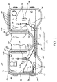
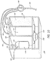
- a sterile surgical tray 10 is shown in FIG. 1 .
- the tray 10 includes structure 12 for receiving a plurality of surgical instruments 14.
- the structure 12 for receiving the instruments 14 may be a mating structure, such as shown, that generally conforms to the shape of a particular instrument.
- the term "mating" means without limitation a receptacle having a complementary shape for recessing part or all of an article.
- the structure 12 could be a recess (not shown) in the tray 10 having a shape that may hold a variety of instruments 14 or the structure 12 may be cavities (not shown) formed in tray 10 that retain instruments 14 in a generally vertical orientation relative to top surface 16, or even some other suitable structure 12 may be used.
- the tray 10 should have sufficient area on top surface 16 to receive the surgical instruments 14 necessary for the surgery to be performed with sufficient space between the instruments 14 to allow the surgeon to easily and conveniently pick-up an instrument and return it to the tray 10.
- the sterile tray 10 may be molded of such materials as acrylonitrile butadiene styrene (ABS) or similar thermoplastic material.
- ABS acrylonitrile butadiene styrene
- the tray 10 may take the place of the traditional Mayo tray and may be placed between the surgeon and the surgical site. Therefore, it is preferred that tray 10 be sturdy enough to withstand the weight of a surgeon's arms resting on the structure forming arm rests 18. However, other accommodation may be made for a surgeon's arms and tray 10, in which case, tray 10 need not be as robustly constructed.
- Tray 10 also may include structure forming a priming fluid reservoir 20 for receiving one or more instruments 14 during priming of one or more instruments with a surgical fluid such as balanced-salt solution (BSS), as is well known. If a reservoir 20 is not provided the user may need to use a beaker or other container for priming (for example, filling) the surgical instruments and tubes with BSS.
- a surgical fluid such as balanced-salt solution (BSS)
- BSS balanced-salt solution
- Structure 22 for attaching a drape 24 to the tray 10 may also be provided.
- the drape 24 may be placed over a patient, such as a portion of a patient's head (not shown) during ophthalmic surgery.
- Structure 22 may be any suitable structure such as adhesive tape, hook and loop material, or other structure that will attach drape 24 to tray 10.
- Using drape 24 allows for the use of at least one fluid retention trough 26 to collect fluid runoff from the drape 24 that occurs during surgery.
- FIG. 1 shows two troughs 26, but a single trough (not shown) could also be formed that surrounds the entire center section 28 where a patient's head (not shown) will be placed during surgery.
- the surgical instruments 14 may include a plurality of instruments, and in particular ophthalmic surgical instruments prepackaged and sterilized with the tray 10. Also, at least one surgical instrument 14 may be connected at manufacture to a pump fluid reservoir 30 via tubing 32 and/or 34, as shown in FIG. 1 . If the sterile surgical tray 10 is for ophthalmic surgery the plurality of surgical instruments 14 preferably includes at least a tissue isolation instrument, an aspiration instrument, and an infusion instrument.
- the tissue isolation instrument may be at least one of a vitreous cutter, a lens emulsification, fragmentation, or cutting device, a scissors, and a cautery knife, all of which are well known.
- the aspiration instrument may be incorporated into the tissue isolation instrument, such as is known in vitreous cutters and phacoemulsification (phaco) devices.
- the aspiration and infusion instruments may be a combined infusion and aspiration instrument, commonly referred to as an irrigation/aspiration (I/A) handpiece. If the surgical tray 10 is for vitreoretinal surgery the infusion instrument may be an infusion cannula and connected tubing.
- Additional surgical instruments may include an illumination instrument, which is preferably self-illuminating. That is the illumination instrument preferably has a built-in light source and not the commonly known remote light source-fiber optic combination.
- tray 10 may include additional items such as entry site alignment cannulas 36, commonly used in sutureless vitreoretinal surgery.
- tray 10 includes all or nearly all the instruments necessary to perform the desired surgery.
- tray 10 if the desired surgery is a vitrectomy of the eye, includes the instruments for a vitrectomy, which are a vitreous cutter, an irrigation instrument, an illumination instrument, an aspiration source, an infusion source, and passive surgical instruments (for example, not powered), and possibly an air/fluid exchange source.
- the instruments included in tray 10 would be a cataract extraction instruments such as a phaco device, a phaco needle, a capsule polish tool, an aspiration source, an infusion source, and passive surgical instruments, and possibly an oil filled syringe.
- Tray 10 also preferably includes structure for receiving additional instruments beyond the plurality of instruments that are prepackaged and sterilized with the tray 10; an example of which is the empty space, shown generally at 38 in FIG. 1 .
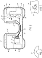
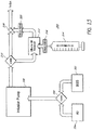
- the sterile surgical tray 10 also includes a pump(s) 40 contained within the sterile tray 10 operatively connected to the pump fluid reservoir 30.
- a motor(s) 42 is also contained within the sterile tray 10 and is connected to the pump 40.
- the sterile surgical tray 10 can be configured to releasably receive a motor(s) and a pump(s), and/or be mechanically and/or electrically coupled to a motor(s) and a pump(s), which may or may not be partially or entirely sterile because in certain embodiments, the motor(s) and/or pump(s) may be reused with other sterile surgical trays.
- reservoir 30 is not easily removable from tray 10.
- Other embodiments may provide a reservoir, pump, motor assembly that is self-contained and placed in a pocket or cavity (not shown) of tray 10 so that the assembly can be removed from tray 10 easily before, during, or after surgery.
- Reservoir 30 may be an aspiration pump fluid reservoir for collecting aspirated tissue and fluid during surgery or reservoir 30 may be infusion pump fluid reservoir for infusing fluid into a surgical site.
- reservoir 30 is actually both an aspiration reservoir 44 and an infusion pump fluid reservoir 46; such that infusion reservoir 46 and aspiration reservoir 44 form a single fluid reservoir 30 with separate chambers for infusion and aspiration and a pump operatively connected to each chamber. Therefore, in the configuration of FIG. 2 pump 40 is an infusion pump and pump 48 is an aspiration pump.
- Motors 42 and 50 are preferably electric motors and may be the same type motor or different motors depending on the performance needed to drive the pumps 40 and 48.
- Aspiration pump 48 is preferably a suitable pump for aspirating a sufficient amount of tissue and fluid at an acceptable rate for the type of surgery to be performed.
- pumps 40 and 48 may be one of a vacuum pump (for example, a rotary vein or diaphragm) or a positive displacement pump (for example, peristaltic or scroll).
- Tray 10 may also include a syringe pump (not shown) for injecting oil or other fluids into the eye.
- the inclusion of a pump and reservoir in tray 10 provides particular fluidics advantages over traditional console based systems.
- fluidics advantages can be achieved because the construction and functionality of tray 10 allow the pump fluid reservoir to be less than two feet from a surgical site, such as an eye. This close proximity can allow for infusion and aspiration tubing lengths of less than two feet and perhaps less than 18 inches to be used.
- compliance of the fluidics circuit defined by the path from the infusion reservoir 46 through infusion tubing and a surgical instrument into the eye followed by an aspiration out of the eye through aspiration tubing and into the aspiration reservoir 44 can be greatly reduced compared to the conventional console based surgeries known today.
- Tray 10 may have a shape that conforms to a contour of a body portion adjacent a surgical site. As can be seen from FIGs. 1 and 2 tray 10 is curved so that the tray 10 may be placed around a patient's head (not shown) during ophthalmic surgery. Tray 10, which can be said to be generally U-shaped, would be placed such that a top of the patient's head is placed nearest the wall 52 or, put another way, at the bottom of the U-shaped section 28. The sterile surgical tray for ophthalmic surgery may also be semi-circular in shape, as shown at 54 in FIG. 3 . Fluid reservoir 30 is preferably located to a side of the patient's head during surgery, as shown in the embodiment of FIGs. 1 and 2 .
- Fluid reservoir 30 may be a rigid housing formed of suitable material such as some form of plastic or resin.
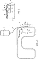
- the Pump fluid reservoir may also be a bag 56, shown in FIG. 4 .
- a sterile surgical tray 58 similar to tray 10, in the embodiment of FIG. 4 includes a remotely located infusion source 60, such as a BSS bottle that may be hung from an IV pole (not shown).
- Infusion source 60 is connected to a surgical instrument 62 via tubing 64 (preferably included in tray 58 during manufacture).
- Instrument 62 is connected to a pump 66 via tubing 68.
- Pump 66 is powered by a motor 70, seen in FIG. 5.
- FIG. 5 is a partial elevation view of the inside of tray 58 taken along line 5-5 of FIG. 4 .
- Pump 66 aspirates tissue and fluid from a surgical site into bag 56 via tubing 72. Bag 56 may be hung from structure on tray 58 such as hooks 74.
- fluid reservoir 30 preferably includes a filler port 76 for allowing a user to fill the fluid reservoir 46 with a surgical fluid to be infused into a surgical site.
- Fluid reservoir 44 preferably includes a discharge port for emptying aspirated fluid when the reservoir 44 becomes full during surgery.
- FIG. 6 shows an aspiration and infusion reservoir 100, including isolated aspiration reservoir 102 and infusion reservoir 104.
- Reservoir 100 includes a separate pump and motor for each chamber 102 and 104.
- An aspiration pump 106 and motor 108 will aspirate fluid and tissue from a surgical site through surgical instrument 110 via tubing 112.
- Infusion fluid contained within infusion reservoir 104 is forced from reservoir 104 through tubing 114 to an infusion instrument (not shown) by infusion pump 116 and motor 118 pressurizing reservoir 104.
- An example of an infusion instrument can be an infusion cannula that is inserted into the eye to allow infusion fluid to enter the eye and maintain internal eye pressure to prevent collapse of the eye.
- pumps and motors 106, 108, 116, and 118 are contained within a chamber 120 of reservoir 100. It is possible that because of the isolation of the pumps and motors in chamber 120 that they may not need to be sterilized along with reservoir 100 and its associated tray and surgical instruments after packaging at a manufacturer. It is accepted protocol that any surface that comes in direct contact with the infused or aspirated fluids should be sterile. Though an associated tray is not shown with reservoir 100 it is easily understood that reservoir 100 could be retained in and prepackaged and sterilized with a tray in a similar fashion to that described above relative to tray 10. In addition, it is possible that reservoir 100 may be removed from a tray and placed or hung by ledge 122 at a convenient location for surgery.
- Tray 10 further includes a power connector 80 connected to motors 42 and 50 for connecting motors 42 and 50 to a power source 82 via lines 84.
- Power source 82 is shown in FIG. 2 as a battery but the power source could be at least one of a direct current (DC) source, an alternating current (AC) source, a fuel cell, or a wireless power source, such as Witricity, or some other suitable power source.
- So power connector 80 can be at least one of an AC connector, a fuel cell connector or a wireless power connector instead of the battery connector shown.
- FIG. 2 shows one power source connection but it is to be understood that multiple power sources may be used.
- power source 82 may not be prepackaged and sterilized with tray 10 as shown, but rather, may be a power source that is connected to tray 10 after tray 10 is opened and is being prepared for surgery.
- Power connector or connectors 80 may be attached to a portion of tray 10, such as in a side wall of tray 10, as shown in FIG. 7 ; where power connector 80 is for connection to a DC source, an AC source, or an AC cord (not shown) to be plugged into a wall socket (not shown). If wireless power transmission is used it is possible that lines 84 can be eliminated if the surgical instruments are able to incorporate the power transmission apparatus. Obviously not all surgical instruments need power and some instruments may be self-powered by battery or fuel cell.
- tray 10 In the case where a power source is connected after tray 10 is opened, it may not be necessary for the power source to be sterile.
- the lower portion of tray 10 may have an opening for accepting a battery pack or fuel cell.
- a non-sterile battery pack or fuel cell could potentially be used because it is below the sterile field top surface 16 of tray 10.
- Power connector 80 may be connected directly to motors 42 and 50 and at least one surgical instrument 14 such that power source 82 powers the pumps and at least one surgical instrument 14, as shown in FIG. 2 .
- At least one surgical instrument 14 is connected to power connector 80 through one of lines 84, an input and output connector 86, and line 88 (shown in FIG. 1 ).
- more than one surgical instrument 14 may also be connected to power connector 80 through other input and output connectors 86, though these are not shown.
- the surgical instruments that can be connected include a vitreous cutter, a lens emulsification, fragmentation, or cutting device, an illumination device, and a scissors.
- the surgical instruments 14 may be prepackaged and sterilized with tray 10 and connected to pump reservoir 30 and input and output connectors 86.
- power distributor 90 may be desired for distributing power throughout the sterile tray 10 for powering a plurality of surgical instruments.
- power distributor 90 may take on many forms, such as a voltage transformer, a DC-to-DC converter, and an AC-to-DC converter.
- power distributor 90 may also include a processor for performing control functions to operate the surgical instruments, motors, and operator feedback or status indicators, in other words power distributor 90 may also be the central controller for the entire surgical operation to be performed.
- Tray 10 preferably includes structure for connecting a sterile barrier to tray 10, such as slots 92.
- a sterile barrier 94 is attached to tray 10 in FIG. 8 .
- Sterile barrier 94 includes a pliable sheet 96 that has at least one pocket 95 formed in the sheet 96 for allowing a non-sterile user (not shown) outside a sterile field to manipulate items within the sterile field without compromising the sterile field.
- the sheet 96 is attached to supports 98 that are in turn held within slots 92 of tray 10.
- Pocket 95 is shown as two pockets in FIG. 8 that form gloves for a user. It should be easily understood, that pocket 95 may take on other forms than gloves. For example, pocket 95 could simply be a cavity without any structure forming finger openings.
- Tray 10 in addition to having structure for receiving a plurality of surgical instruments, preferably includes a plurality of input and output connectors 86 attached to tray 10, as seen in FIGs. 1 and 2 .
- sterile surgical tray 10 preferably includes pump fluid reservoir 30 contained within sterile tray 10, a pump or pumps 40 and 48, and a motor or motors 42 and 50 connected to the pumps and at least one of the input and output connectors 86 is connected to the motors 42 and 50 for connecting the motors 42 and 50 to a power source 82, such as the battery shown.
- Tray 10 further may include at least one status indicator 130 attached to at least one of the output connectors 86.
- the status indicator may be a light emitting diode (LED) or an audible signal generator.
- LED light emitting diode
- FIG. 1 on the left side three status indicators 130 are shown adjacent a surgical instrument 14.
- the three status indicators 130 could provide different types of feedback to a user. For example, if reservoir 30 included a sensor the indicators 130 could be red, yellow, and green in color to indicate to the user that a vacuum level is unacceptable (red), a vacuum level is approaching an unacceptable level (yellow), or the vacuum level is acceptable (green).
- the indicators 130 could indicate a speed or energy level of the instrument where all three indicators are on when the speed or energy level is high, two indicators are on when the speed or energy level is at an intermediate level, and one indicator is on when the speed or energy level is low.
- tray 10 is used in an operating room that may be dark for certain surgeries, such as ophthalmic surgery, it is desirable that a plurality of LEDs 132 are connected to a plurality of output connectors 86 and at least one LED 132 is connected to tray 10 adjacent each of a plurality of surgical instrument retaining recesses 12 for illuminating a location of the surgical retaining recesses 12 on the tray 10.
- a plurality of surgical instruments 14 are retained in tray 10 and connected to a portion of the plurality of input and output connectors and prepackaged and sterilized with the tray.
- tray 10 may be sufficiently narrow at a location 134 that will be immediately between a patient and a surgeon to allow the surgeon unrestricted access to a surgical site.
- location 134 is in the center of tray 10 and forms the bottom of the U-shape of tray 10.
- tray 10 includes a plurality of surgical instruments retained in tray 10 and connected to a portion of the plurality of input and output connectors 86, that the input and output connectors 86 connected to the plurality of surgical instruments are attached to tray 10 at a generally central location 134, so that the connected instruments may be placed on either side of the tray to accommodate either a left or right handed surgeon.
- the status indicators 130 may also be placed on tray 10 to indicate a power level of a battery or fuel cell, a fluid level of a pump fluid reservoir attached to the input and output connectors or an illumination level of an illuminator attached to the input and output connectors.
- An alternative or supplement to the status indicators and LEDs 130 may be a display 136 for displaying, via numbers, icons, bar graphs, and the like, the status of the instruments and/or other apparatus connected to tray 10.
- tray 10 may also have a processor attached to the input and output connectors 86 for receiving inputs from a user and a plurality of surgical instruments 14 and devices attached to the input and output connectors 86 and for transmitting signals to a user and the plurality of surgical instruments 14 and devices.
- the processor may be part of power distributer 90 or it may be a separate device.
- the processor may also be prepackaged and sterilized with tray 10 or it may be connected to tray 10 after tray 10 is opened and is being prepared for surgery.
- Tray 10 may also include a wireless transceiver 138 connected to the input and output connectors 86 for transmitting and receiving signals to and from remote devices and surgical instruments.
- Wireless transceiver 138 may be any acceptable type of wireless communication device such as an infrared or radio frequency transceiver.
- radio transceivers include Bluetooth®, Zigbee®, Wifi or IEEE 802.11 transceivers, or other known wireless communication devices.
- the wireless transceiver 138 can be connected a processor connected to tray 10 and to a laptop computer (not shown) in the operating room or elsewhere for monitoring or controlling a surgical procedure through the information flowing throughout tray 10 and the input and output connectors 86.
- some of the input and output connectors 86 may be connected to user input buttons, knobs 33, or the like.
- a foot control connector 140 may be attached to tray 10 for connecting a foot controller 142 shown in FIG. 9 .
- foot controller 142 may also be connected to tray 10 via wireless transceiver 138 as indicated by symbol 144 in FIG. 9 .
- a portion of the input and output connectors 86 are for connection to additional instruments beyond the plurality of instruments prepackaged and sterilized in tray 10. For example, a surgeon performing vitreoretinal surgery may require a fragmentation instrument that is not included in prepackaged and sterilized tray 10 but it can be connected to tray 10 using a mating input and output connector 86.
- Infusion reservoir 150 is a multiple chamber fluid reservoir for holding a different fluid in each chamber.
- a pressure pump 152 is connected to two or more chambers 154, 156, and 158 for pressurizing the chambers.
- a multiple position valve 160 is connected to the multiple chambers 154, 156, and 158, via tubing 162.
- Valve 160 allows a fluid contained in a selected chamber to flow out of the selected chamber and into an eye or other surgical site through tubing 164 and a surgical instrument (not shown).
- Valve 160 is shown as a well known three position stop cock but valve 160 could also be individual valves or mechanically or electrically actuated valves depending on the design.
- valve 160 If valve 160 is electrically actuated it could be attached or contained within tray 10 and connected to a portion of the input and output connectors 86 to support other than manual selection of the position of valve 160.
- the infusion fluid reservoir 150 shown has three chambers 154, 156, and 158, each chamber holding one of BSS, silicone oil, and a gas, which are particularly useful in ophthalmic surgery; but other fluids could be held in the chambers depending on the requirements of the particular surgery to be performed.
- one of the chambers could contain viscoelastic.
- Infusion reservoir 150 is also preferably transparent so that a user can easily see the fluid levels in chambers 154, 156, and 158. It should also be appreciated that infusion fluid reservoir 150 has use beyond use with tray 10 and could be used with other surgical systems.
- Infusion pump 152 powered by motor 166 pressurizes multiple chambers 154, 156, and 158 for infusing multiple fluids into a surgical site. It should be understood that motor 166 is connected to input and output connectors 86 (not shown) for power and control. Chambers 154, 156, and 158 also preferably include access ports 168 for filling or refilling the chambers. Ports 168 can require caps or closure devices to prevent fluids from leaking and to allow the chambers to be adequately pressurized.
- the chamber 154 shows a bag 170 partially filled with a fluid 172. Fluid 172 may be BSS or other liquid.
- Chamber 154 includes bag 170 at least partially filled with BSS such that pump 152 pressurizes the fluid reservoir chamber 154 during surgery to force BSS 172 from the fluid reservoir 150.
- Chamber 156 may hold silicone oil 174 and chamber 158 may hold a gas 176.
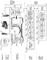
- FIG. 11 shows an example of a sterile surgical tray 180 including a plurality of surgical instruments including the instruments to perform a vitrectomy of an eye.
- a vitrectomy at least an illumination instrument, a tissue cutting instrument, an infusion instrument, an entry site alignment system, and a surgical knife would typically be included in a sterilized tray such as tray 180.
- FIG. 12 shows an example of a sterile surgical tray 182 including a plurality of surgical instruments including the instruments to perform a cataract removal from an eye.
- a cataract removal at least a lens emulsification device, an infusion device, viscoelastic, a rhexis forceps, an intraocular lens insertion instrument, and a surgical knife would typically be included in a sterilized tray such as tray 182.
- FIG. 13 is a functional block diagram of a fluid-air exchange system 300 is an alternative to pump reservoir 150 that may be incorporated into a sterile surgical tray, such as tray 10.
- System 300 preferably includes a BSS reservoir 302, a reservoir 304 of air, connected to a selector valve 306 for selecting which fluid, BSS or air, will be allowed to flow into infusion pump 308.
- Infusion pump 308 may be any suitable pump for infusing fluid into an eye or other body part.
- a bypass valve 310 connects a flow path from infusion pump 308 and an oil reservoir 312. Oil reservoir 312 is connected to a source of oil 314 via a check valve 316.
- Oil source 314 may be a syringe, as shown or may be another source that is connected to a pump (not shown) for automatically pumping oil into reservoir 312. Oil reservoir is then connected to a three-way stopcock valve 318 via another check valve 320. Depending on the positions of the valves 306, 310, and 318 air, BSS, or oil (typically silicone oil) will be infused into an eye. Bypass valve 310 allows infusion pump and air or BSS to push oil from reservoir 312 into an eye.
- the independent surgical tray 1402 can include at least the sterile surgical tray as described herein as illustrated in FIG. 14 .
- the independent surgical center 1402 can be coupled to various surgical/medical or other devices 1401, a personal surgical center 1410, and/or a hospital/medical office system 1414.
- the independent surgical center can be operable without the use of an external surgical console, and can act as a standalone system.
- the independent surgical center can also be coupled to various surgical and/or other devices 1401 (also referred to herein as handpieces), for example but not limited to an illumination device 1407, foot pedal input device 1406, cutting device 1408 (also referred to as a biological tissue cutting device, as further described below), irrigation device, infusion device, viewing device, aspiration device, lasering device, cauterizing device, resecting device, lens emulsification device, fragmentation device, lens cutting device, scissor device, or any other like devices.
- the foregoing surgical and/or other devices can comprise a power source (internal or external, AC/DC), processing unit, network interface (wired or wireless), electronics, memory, audio mechanism, and the like.
- the independent surgical center 1402 communicates and/or is coupled/connected to the various surgical and/or other devices through a network interface 1440.
- the network interface 1440 can operate on a wired connection and/or a wireless connection using Bluetaoth®, Zigbee®, Wifi or IEEE 802.11, or any other wireless communication protocol.
- the network interface 1440 can be coupled to a battery pack 1442, which can be received in, coupled to, and/or removed from the independent surgical center 1402.
- the battery pack 1442 comprises without limitation a battery or a plurality of batteries 1444, and a processing unit 1446.
- the processing unit can be in the independent surgical center 1402, the personal surgical center, a separate console, and/or the surgical devices, as described herein.
- the battery pack 1442 can comprise electrical contact and/or connectors for allowing the battery 1444, the processing unit 1446 (for example, Intel® 8085 microprocessor), and/or the network interface 1440 to be coupled and/or to connect to the circuitry and/or electronics 1412.
- the processing unit 1446 is configured to execute programming instructions stored in memory within the electronics 1412 to control light emitting diodes (LEDs) 1448, and/or receive user input through control knobs, buttons, or other input devices 1450.
- the processing unit can be configured to control the LEDs to indicate/show the cutting device's status, speed, or other like indicators.
- the processing unit 1446 can also be configured to communicate with the motors 1452 coupled to the pumps 1454.
- the processing unit 1446 can also be configured to communicate and/or transmit commands to the surgical and/or other devices 1401 or to the personal surgical center 1410.
- the battery pack 1442 can be disposable or can be reused with other independent surgical centers 1402.
- the battery pack 1442 can be sterile or non-sterile, in which case the battery pack cannot be within the surgical field.
- the battery pack 1442 is reused with other independent surgical centers 1402 because of the cost of the batteries 1444, the processing unit 1446, and/or the network interface 1440, but in certain embodiments, the battery pack 1442 is disposable for purposes of sterility.
- the independent surgical center can also be coupled to a personal surgical center 1410.
- the personal surgical center 1410 can control the independent surgical center 1402.
- the personal surgical center 1410 can also include without limitation a console, general purpose computer, laptop computer, networked device(s), or the like that can be configured to monitor and/or display the settings of the various medical instruments (for example, the handpieces and/or surgical devices) on display or a touch screen input display 1428. Additional embodiments of the personal surgical center 1410 are described below.
- the personal surgical center 1410 can include without limitation a log database 1430 for storing real-time data and/or periodic data and status levels obtained and/or received from the independent surgical center.
- the personal surgical center 1410 can generate and/or store reports using the reports system and/or database 1432.
- the personal surgical center 1410 can also initiate billing procedures using the billing module 1434 that can interface with a billing system and database 1420.
- the personal surgical center 1410 can also store the data, status levels, and/or patient information in the patients records database 1422 using patient records module 1436, or can store this data in the hospital information system (HIS) 1424 using the HIS interface module 1438.
- HIS hospital information system
- the personal surgical center 1410 monitors and displays the settings and status of the various surgical and/or other devices while the independent surgical center controls the medical instruments via the circuitry and electronics 1412 in the independent surgical center, and the circuitry and controls in the various surgical and/or other devices.
- the personal surgical system 1410 can be coupled to other hospital/medical office systems 1414.
- FIG. 14 also illustrates one embodiment of a hospital/medical office system 1414, which can include without limitations systems and databases 1416 for logging data from the personal surgical center 1410, systems and databases 1418 for generating reports, systems and databases 1420 for producing invoices, bills, and/or insurance claims, systems and databases 1422 for storing patient records, systems 1424 for interfacing with hospital information systems (HIS).
- systems and databases 1416 for logging data from the personal surgical center 1410
- systems and databases 1418 for generating reports
- systems and databases 1420 for producing invoices, bills, and/or insurance claims
- systems and databases 1422 for storing patient records
- systems 1424 for interfacing with hospital information systems (HIS).
- HIS hospital information systems
- the independent surgical center 1402 and surgical and/or other devices can be located within the sterile field in which a surgery is performed, while the personal surgical center, and the hospital/medical office systems can be located outside the sterile field.
- the biological tissue cutting and/or aspiration handpiece (for example, vitrectomy handpiece or other like handpieces) is portable, lightweight and can be powered by battery to power the cutter and/or aspiration. It can be used in the field, offices, surgery centers and operating rooms.
- the biological tissue cutting and/or aspiration handpiece may be used as a standalone instrument or in conjunction with the independent surgical center discussed above.
- the handpiece may be disposable and can be connected to the aspiration/infusion cassette, which provides aspiration pressure to the cutter.
- FIG. 6 illustrates on example of an aspiration/infusion cassette 100 with the infusion line 114 and the biological tissue cutting and aspiration handpiece 110.
- the left side of the cassette functions to provide aspiration pressure to the biological tissue cutting and aspiration handpiece, while the right side provides infusion.
- the biological tissue cutting and/or aspiration handpiece is a disposable handpiece such as that described in co-pending U.S. Patent Publication No. 2008-0208233 A1 ( U.S. Patent Application No. 11/963,749 ) titled Disposable Vitrectomy Handpiece, filed December 21, 2007, the entire content of which is incorporated herein by reference.
- the biological tissue cutting and/or aspiration handpiece can incorporate battery power or other power supply, and a flow controller/pinch valve.
- the handpiece may wirelessly communicate (for example, Bluetooth or the like) with other surgical instruments, an internal or external monitor or speaker, or a control center in the aspiration/infusion cassette.
- the handpiece may wirelessly communicate with a personal surgical center and/or an independent surgical center.
- Surgical parameters for example, cut speed, frequency, aspiration pressure/flow rate
- Surgical parameters may be controlled directly on the handpiece, or via a foot pedal wirelessly connected to the handpiece.
- Such parameters may control a cutting tip, aspiration pump, and the like.
- the drive circuitry may be incorporated directly in the handpiece, in the surgical tray, or aspiration/infusion cassette depending on how the handpiece is powered (for example, by battery or through the aspiration/infusion cassette).
- the biological tissue cutting and/or aspiration handpiece can be a stand-alone instrument, not used with an external control center.
- the handpiece can be used in conjunction with other standalone instrumentation, such as an illumination device.
- the controls for the handpiece are located on the handpiece itself, eliminating the need for a surgical console.
- the handpiece itself or the surgical tray may have a display or speaker to inform the surgeon of current surgical settings and instrument faults.
- the handpiece includes a control unit or processing unit which may be, for example, a microprocessor based unit, an ASIC, or the like, and other circuitry.
- the biological tissue cutting and/or aspiration handpiece can be used in conjunction with an aspiration/infusion cassette that includes a control center or in conjunction with an external, laptop control center.
- an aspiration/infusion cassette that includes a control center or in conjunction with an external, laptop control center.
- battery power can enable better maneuverability of the handpiece.
- the battery may be placed inside the handpiece, surgical tray or at the aspiration/infusion cassette itself. When the battery is placed inside the handpiece, it adds weight and size to the unit, and can reduce maneuverability and ergonomics.
- the aspiration/infusion cassette can be larger and heavier because ergonomics on this instrument are not as critical. However, when the battery is placed at the aspiration/infusion cassette or surgical tray, an electrical line would need to be tethered to the handpiece along with the aspiration line.
- the wireless control may be mounted in the handpiece, the aspiration/infusion cassette, the surgical tray, or all of the above. If the handpiece uses battery power and includes no link to the aspiration cassette or surgical tray, wireless communication will generally be within the handpieces, surgical tray, and other devices. However, if there is a direct-wired link between the two, wireless communications may then be with certain devices, for example the surgical tray. In certain embodiments, the wireless communication will be within the aspiration/infusion cassette or surgical tray to reduce the weight of the handpiece. In certain embodiments, the battery / power source for the biological tissue cutting and/or aspiration handpiece, the network communication, and the aspiration originate from the surgical tray through a direct wire connection.
- the handpiece may include a display and/or speaker for relaying information regarding instrument status, fault, cut speed, or the like.
- the handpiece may include a LED and/or speaker on the handpiece itself.
- the instrument and operation information may also be shown on a display or speaker on the surgical tray or may be displayed on a personal surgical center or a laptop center to allow the surgeon to more easily review such information.
- the biological tissue cutting and/or aspiration handpiece may communicate with the personal surgical center or the laptop directly or indirectly through the independent surgical tray or surgical tray.
- the personal surgical center or laptop center can indicate the instrument and operation information, such as current cut speed, battery life (if applicable), any faults, or any other indicator or status information. It may also receive additional information, such as the maximum cut speed permissible and other surgical parameters.
- the biological tissue cutting and/or aspiration handpiece can identify itself to the independent surgical center, and/or personal surgical center and/or laptop center, and indicate whether it has been used before. If flow sensing or flow control is used, the sensors and actuators may be placed close to or directly on the biological tissue cutting and/or aspiration handpiece.
- FIG. 14A illustrates a block diagram of one embodiment of a computing system (which can be a fixed system or mobile device) that is in communication with one or more independent surgical centers 910 and/or one or more surgical devices 915 via one or more networks 910.
- the computing system 900 may be used to implement one or more of the systems and methods described herein.
- the computing system 900 may be configured to process status data and/or information from surgical devices. While FIG. 14A illustrates one embodiment of a computing system 900, it is recognized that the functionality provided for in the components and modules of computing system 900 may be combined into fewer components and modules or further separated into additional components and modules.
- the system 900 comprises processing and analysis modules 906 that carry out the functions, methods, and/or processes described herein.
- the processing and analysis modules 906 may be executed on the computing system 900 by a central processing unit 904 discussed further below.
- the processes, systems, and methods illustrated above may be embodied in part or in whole in software that is running on a computing device.
- the functionality provided for in the components and modules of the computing device may comprise one or more components and/or modules.
- the computing device may comprise multiple central processing units (CPUs) and a mass storage device, such as may be implemented in an array of servers.
- the computing system 900 also comprises a laptop computer suitable for controlling and/or communicating with databases, performing processing, and generating reports from databases.
- the computing system 900 also comprises a central processing unit ("CPU") 904, which may comprise a microprocessor.
- the computing system 900 further comprises a memory 905, such as random access memory (“RAM”) for temporary storage of information and/or a read only memory (“ROM”) for permanent storage of information, and a mass storage device 901, such as a hard drive, diskette, or optical media storage device.
- the modules of the computing system 900 are connected to the computer using a standards based bus system.
- the standards based bus system could be Peripheral Component Interconnect (PCI), Microchannel, SCSI, Industrial Standard Architecture (ISA) and Extended ISA (EISA) architectures, for example.
- PCI Peripheral Component Interconnect
- ISA Industrial Standard Architecture
- EISA Extended ISA
- the exemplary computing system 900 comprises one or more commonly available input/output (I/O) devices and interfaces 903, such as a keyboard, mouse, touchpad, and printer.
- the I/O devices and interfaces 903 comprise one or more display devices or touch screen display devices, such as a monitor, that allows the visual presentation of data to a user. More particularly, a display device provides for the presentation of GUIs, application software data, and multimedia presentations, for example.
- the I/O devices and interfaces 903 also provide a communications interface to various external devices.
- the computing system 900 may also comprise one or more multimedia devices 902, such as speakers, video cards, graphics accelerators, and microphones, for example.
- the computing system 900 may run on a variety of computing devices, such as, for example, a server, a Windows server, a Structure Query Language server, a Unix server, a personal computer, a mainframe computer, a laptop computer, a cell phone, a personal digital assistant, a kiosk, an audio player, and so forth.
- the computing system 900 is generally controlled and coordinated by operating system software, such as z/OS, Windows 95, Windows 98, Windows NT, Windows 2000, Windows XP, Windows Vista, Linux, BSD, SunOS, Solaris, or other compatible operating systems.
- the operating system may be any available operating system, such as MAC OS X.
- the computing system 900 may be controlled by a proprietary operating system.
- Conventional operating systems control and schedule computer processes for execution, perform memory management, provide file system, networking, and I/O services, and provide a user interface, such as a graphical user interface ("GUI”), among other things.
- GUI graphical user interface
- the computing system 900 is coupled to a network 910, such as a LAN, WAN, or the Internet, for example, via a wired, wireless, or combination of wired and wireless, communication link 915.
- the network 910 communicates with various computing devices and/or other electronic devices via wired or wireless communication links.
- the network 910 is communicating with one or more independent surgical centers 910 and/or one or more surgical devices 915.
- Computing system may comprise a browser module or other output module that may be implemented as a combination of an all points addressable display such as a cathode-ray tube (CRT), a liquid crystal display (LCD), a plasma display, or other types and/or combinations of displays.
- the browser module or other output module may be implemented to communicate with input devices 903 and may also comprise software with the appropriate interfaces which allow a user to access data through the use of stylized screen elements such as, for example, menus, windows, dialog boxes, toolbars, and controls (for example, radio buttons, check boxes, sliding scales, and so forth).
- the browser module or other output module may communicate with a set of input and output devices to receive signals from the user.
- the input device(s) may comprise a keyboard, roller ball, pen and stylus, mouse, trackball, voice recognition system, or pre-designated switches or buttons.
- the output device(s) may comprise a speaker, a display screen, a printer, or a voice synthesizer.
- a touch screen may act as a hybrid input/output device.
- a user may interact with the system more directly such as through a system terminal connected to the score generator without communications over the Internet, a WAN, or LAN, or similar network.
- the system 900 may comprise a physical or logical connection established between a remote microprocessor and a mainframe host computer for the express purpose of uploading, downloading, or viewing interactive data and databases on-line in real time or periodic basis.
- the remote microprocessor may be operated by an entity operating the computer system 900, including the client server systems or the main server system, an/or may be operated by one or more of the surgical devices 915 and/or one or more of the independent surgical centers 910.
- the network 910 may communicate with other data sources or other computing devices, for example billing systems or hospital information systems.
- the computing system 900 may also comprise one or more internal and/or external data sources.
- one or more of the data repositories and the data sources may be implemented using a relational database, such as DB2, Sybase, Oracle, CodeBase and Microsoft® SQL Server as well as other types of databases such as, for example, a flat file database, an entity-relationship database, and object-oriented database, and/or a record-based database.
- the acts, methods, and processes described herein are implemented within, or using, software modules (programs) that are executed by one or more general purpose computers.
- the software modules may be stored on or within any suitable computer-readable medium. It should be understood that the various steps may alternatively be implemented in-whole or in-part within specially designed hardware. The skilled artisan will recognize that not all calculations, analyses and/or optimization require the use of computers, though any of the above-described methods, calculations or analyses can be facilitated through the use of computers.
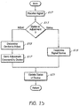
- FIG. 15 is a flow diagram of a process executed by the processing unit 1446 of an independent surgical center in accordance with an embodiment of the invention.
- the process of FIG. 15 represents the process which is performed by the processing unit housed or received in the sterile surgical tray as described herein. In some embodiments of the invention, the process may be performed in another instrument or component of the system, based on where the processing unit is located in the system. In some embodiments, the system may include multiple processing units, and the process of FIG. 15 may be performed by one or more of the multiple processing units.
- the process receives a signal from an instrument in communication with the independent surgical center.
- the tray may receive the signals from an instrument through a wired connection, for example, the handpiece, or may receive the signals from an instrument through a wireless connection, for example, from the illumination device.
- the process determines whether the received signal is a status update signal or an adjustment request signal.
- the processing unit may be used to adjust operation parameters of selected instruments, and may also be used to process and communicate to a user the status of the same or other instruments. If the processing unit determines that the signal is an adjustment request signal, the process proceeds to block 615. If the processing unit determines that the signal is a status update signal, the process instead proceeds to block 619.
- the process determines the device for which the adjustment signal is directed.
- the adjustment signal may be received by a user control directly connected to the processing unit.
- the adjustment signal may originate from a user control controlling the infusion device located alongside the processing unit in the tray.
- the adjustment signal may be received wirelessly from a user control located on a remote instrument, for example, a foot pedal associated with the tray.
- Some of the adjustment requests may be meant for the device or component from which the signal originated, while some other of the adjustment requests may be meant for a different device, whether it is a device on the tray or on a completely separate instrument in the surgical system.
- the processing unit determines the intended destination device or instrument.
- the process sends an adjustment command to the destination device or instrument.
- the adjustment command may be an unaltered adjustment signal, where the processing unit acts as a switch or routing device for the system, or the adjustment command may be a wholly new command signal generated by the processing unit based on a received adjustment request signal, for example, a received signal as was described above with respect to block 611.
- the operational settings or parameters of the device are adjusted in accordance with the adjustment command.
- status update signals include status update information of the device from which the status update signal originated.
- the status update information may include various information about an originating device, for example, current settings, operating parameters, remaining power levels, instrument fault conditions, and other information. Status information for each specific instrument in the system is different depending on the functionality of the instrument. For example, a handpiece may provide status of cut speed of a cutter or aspiration levels, whereas an illumination device may provide illumination level status.
- the process updates the status of a device or instrument.
- the processing unit of the system may update status information pertaining to the received signal.
- the processing unit may update the status information of the destination device to which the adjustment request was sent.
- the processor may directly update the status information of the device from which the status update signal originated, based on the contents of the status update signal.
- the processing unit may display the status updates on, for example, a monitor located on the instrument housing the processing unit.
- the status updates may be expressed visually through changes to, for example, LED indicators, or aurally through, for example, audio alerts outputted through available speakers.
- visual or aural status indicators may be available on various other instruments of the system in addition to, or in lieu of, the instrument housing the processing unit.
- the processing unit may send the status update information to an appropriate instrument for output or user feedback purposes.
- the update information is transmitted to the personal surgical center for logging in a log file generated for the surgical procedure. After the status updates have been applied to or recorded by the system, the process returns.
- the independent surgical center 1402 and/or the processing unit 1446 and/or the personal surgical center 1410 as described herein can be configured to receive status and/or adjustment data from, or determine the status of the various surgical and/or devices 1401.
- the independent surgical center 1402, and/or the processing unit 1446, and/or personal surgical center 1410 can be configured to invoke various safety mechanism procedures, for example but not limited a cutter safety mechanism procedure and a low fluid safety mechanism procedure.
- Process 1601 can be segmented into at least four different stages, initial setup, steady state, cutter safety mechanism procedure, and the low fluid safety mechanism procedure.
- Process 1601 starts at block 1602.
- the user and/or surgeon powers on the independent surgical center, the surgical and/other devices at block 1604.
- the processing unit and/or the electronics in the independent surgical center searches, detects, and/or locates available surgical and/or other devices to be employed during the surgery.
- the processing unit and/or the independent surgical center registers the available surgical and/or other devices for the surgery.
- the surgical and/or devices can communicate and/or send to the processing unit and/or the independent surgical center parameter and/or identification information, including but not limited to surgical device identification number, lot number, part number, surgical device name and/or type, current status of device, available options on device (for example, on or off; low, medium, or high speed; or the like).
- the processing unit and/or the independent surgical center obtains and/or receives periodic information/data from the surgical and/other devices in order to determine at block 1610 the status or adjustments made in or to the surgical and/or other devices.
- processing unit and/or the independent surgical center enters a steady state, wherein the processing unit and/or independent surgical center pings, requests, or receives data and/or information from the surgical and/or other devices at block 1612.
- the surgical and/or other devices can be configured to gather, obtain, and/or analyze status and/or other data for sending or transmitting to the processing unit and/or independent surgical center.
- the surgical and/or other devices can be configured to send or transmit, on a real-time, substantially real-time, periodic basis, data and/or other information to the independent surgical center at block 1616, wherein the data and/or other information can comprise without limitation device status information (for example, on or off, activated or deactivated, speed levels, temperature, battery levels, elapsed time, fluid levels, warning and/or error messages, or the like), user inputted adjustment data, device data, or the like.
- the procedure After sending or transmitting the data, the procedure returns to block 1610 to repeat the process.
- the processing unit and/or independent surgical tray can detect when the user or surgeon has activated the cutter device by receiving a status message from the cutter device at block 1618.
- the processing unit and/or the independent surgical center can initiate a cutter safety mechanism procedure before and/or while allowing the cutter device to be activated.
- the processing unit and/or the independent surgical center at block 1620 can be configured to transmit an activation command or signal to the infusion motor and/or pump to initiate delivery of infusion fluids to the surgical site.
- the processing unit and/or the independent surgical center at block 1622 before allowing the cutter device to be activated, or simultaneously with the activation of the cutter, can also be configured to transmit an activation command or signal to the aspiration motor and/or pump to generate a vacuum for removing excess fluid and/or tissue/debris from surgical site, and/or to prime the fluid in the cutter before cutting begins.
- the processing unit and/or the independent surgical center at block 1624 can be configured to transmit an activation command or signal to the cutter motor device. After sending or transmitting the activation commands or signals, the procedure returns to block 1610 to repeat the process.
- the cutter safety mechanism procedure can prevent surgical errors and/or harm to the patient by ensuring that the necessary surgical and/or devices are activated before cutting is initiated.
- the infusion motor must be activated prior to cutting to prevent the collapse of the eye caused by reduced internal eye pressure due to aspirated or leaked vitreous.
- the foregoing procedure can reduce the complexity of the surgery for the surgeon by reducing the number of steps to activate the various necessary devices for the surgery.
- the processing unit and/or independent surgical tray at block 1626 can detect when fluid levels are low and/or high in the various fluid reservoirs by receiving a status message from a fluid chamber device, for example, infusion reservoir 104.
- the processing unit and/or the independent surgical center can initiate a low/high fluid safety mechanism procedure before and/or while the cutter device is activated.
- the processing unit and/or the independent surgical center at block 1628 can initiate and/or activate an alarm sound circuitry within the independent surgical center and/or other surgical device, wherein an audible sound/alarm would be generated to alert the user/surgeon of the low and/or high fluid levels in the various reservoir chambers.
- the processing unit and/or the independent surgical center at block 1630 can also be configured to wait for a period of time (predetermined or user defined), for example, ten seconds, ten minutes, or the like, before receiving and/or obtaining status information from the cutting device.
- the processing unit and/or the independent surgical center can also obtain data and/or information from other surgical devices, such as the fluid reservoir chambers to determine if the fluid levels have been changed. If the cutting device is on and/or the fluid levels have not changed and/or have become worse, then the processing unit and/or the independent surgical center at block 1632 can transmit and/or send a deactivation command to the cutter device and/or the aspiration device. In certain embodiments, the processing unit and/or the independent surgical center will continue to maintain infusion to prevent collapse of the eye. After sending or transmitting the deactivation commands or signals, the procedure returns to block 1610 to repeat the process.
- other surgical devices such as the fluid reservoir chambers
- the high/low safety mechanism procedure can prevent surgical errors and/or harm to the patient by ensuring that the necessary reservoir chambers have sufficient fluid levels during the surgery.
- the infusion of the eye should be continuous to prevent collapse of the eye due to leakage/remove of vitreous fluids, and therefore, low levels of infusion fluids in the infusion reservoir can pose a risk for eye collapse during surgery.
- the foregoing procedure can also reduce the complexity of the surgery for the surgeon by reducing the need for the surgeon and/or the assistant to constantly monitor the fluid levels of the reservoir chambers.
- module refers to logic embodied in hardware or firmware, or to a collection of software instructions, possibly having entry and exit points, written in a programming language, such as, for example, Java, C or C++, or the like.
- a software module maybe compiled and linked into an executable program, installed in a dynamic link library, or may be written in an interpreted programming language such as, for example, BASIC, Perl, Lua, or Python. It will be appreciated that software modules may be callable from other modules or from themselves, and/or may be invoked in response to detected events or interrupts.
- Software instructions may be embedded in firmware, such as an EPROM.
- hardware modules may be comprised of connected logic units, such as gates and flip-flops, and/or may be comprised of programmable units, such as programmable gate arrays or processors.
- the modules described herein are preferably implemented as software modules, but may be represented in hardware or firmware. Generally, the modules described herein refer to logical modules that may be combined with other modules or divided into sub-modules despite their physical organization or storage.
- the present invention also relates to the following items:
Abstract
Description
- The invention is related to a sterile surgical tray that functions as both a pack to transport surgical materials and devices to a surgery site and as a sterile tray for receiving a plurality of surgical instruments. More specifically, embodiments of the invention relates to a sterile surgical tray that includes a pump contained with in the sterile tray and where the pump remains within a sterile field during surgery. The sterile surgical tray may also include a plurality of electrical input and output connectors attached to the tray.
- It is well known to use, in surgery, a sterile pack shipped from a manufacturer to a surgery center, an example of which is ophthalmic surgery (vitreoretinal or cataract surgery, in particular). These packs typically contain several items that are typically used in surgery and include one-time use surgical instruments, fluid cassettes, tubing sets, drapes, needles, and other devices. The particular content of a pack depends on the type of surgery and perhaps the individual preference of the surgeon or surgery center.
- When preparing for surgery, typically a sterile drape is placed over what is commonly referred to as a Mayo tray. The contents of the sterile pack and perhaps additional sterile instruments and materials are spread-out over the tray so that the materials and instruments necessary for the surgery are readily available to a nurse or surgeon.
- It is also known to provide a sterile pack where many of the instruments and tubing sets are organized and placed in mating recesses of the pack so that the pack can act as a tray for at least some of the instruments in surgery.
- Some of the surgical instruments are electrically or pneumatically powered by a surgical console or system that is outside of the sterile field defined by the surgical site and the sterile instruments and materials on the tray and used in the surgery. Some of the sterile materials are removed from the sterile field or a portion is removed from the sterile field prior to surgery. The materials removed include the pump cartridges and tubing sets which are connected to the non-sterile surgical console. The surgical console also typically includes a large display screen for displaying and inputting parameters that will control the devices used during surgery. This surgical set-up typically requires a surgeon and one or two support persons so that surgery can be performed efficiently while also adjusting the parameters on the console and switching to a different surgical instrument to perform a different procedure.
- However, with the present trend of surgeries moving away from hospital and into ambulatory surgery centers (ASCs) and even into a doctor's own office, coupled with reduced reimbursements for surgical procedures, there is a need to allow surgeons to perform surgery with little or no assistance. In addition, because of personnel and cost restraints the assistant provided to the surgeon is typically not trained in the particular surgical procedure to be performed, so that the interaction between the surgeon and assistant may not be particularly efficient.
- Therefore, a need exists for a surgical system and surgical products that allow a surgeon to perform safe, efficient, and cost-effective surgery with little or no assistance during surgery.
- In certain embodiments, a sterile surgical tray comprises a sterile tray, a pump within the sterile tray, and a motor within the sterile tray connected to the pump. Desirably, the tray includes structure for receiving a plurality of surgical instruments. It is also desirable that the tray contain at least one pump fluid reservoir and that the reservoir be operatively connected to the pump. In a distinct embodiment, a sterile surgical tray comprises a plurality of electrical input and output connectors attached to the tray.
- In certain embodiments, an infusion fluid reservoir comprises a multiple chamber fluid reservoir for holding a different fluid in each chamber; a pressure pump connected to two or more chambers for pressurizing the chambers; and a multiple position valve connected to the multiple chambers for selectively opening one of the multiple chambers to allow a fluid contained in a selected chamber to flow out of the selected chamber.
- In certain embodiments, a sterile surgical tray comprises a receiving area for holding a plurality of surgical instruments; a fluid reservoir disposed apart from the receiving area; a pump operatively connected to the fluid reservoir; a motor drivingly coupled to the pump; and a plurality of input and output connectors attached to the sterile tray, at least one of the input and output connectors being connected to the motor. A sterile surgical tray system can comprise in certain embodiments a tray with a top surface defining a sterile surface for holding a plurality of surgical instruments; at least one surgical instrument held on the top surface; a pump fluid reservoir for use with the at least one surgical instrument; a pump operatively connected to the at least one surgical instrument and to the pump fluid reservoir; a motor connected to the pump for driving the pump; and wherein at least the pump remains within a sterile field during surgery.
- In certain embodiments, a sterile surgical tray comprises a top surface for holding a plurality of surgical instruments; a pump connected to the sterile tray and for connection to a fluid pump reservoir; and a motor connected to the pump for powering the pump. A sterile surgical tray can comprise in certain embodiments a tray having a sterile top surface for holding a plurality of surgical instruments; a pump fluid reservoir prepackaged and sterilized with the tray; a pump in the tray for operative connection to at least one surgical instrument and the pump fluid reservoir; and a motor connected to the pump for powering the pump.
- In certain embodiments, an independent system for a surgical procedure comprises a control device including a processing unit; and a plurality of instruments associated with the surgical procedure and operably coupled to the control device, wherein the control device and the plurality of instruments are prepackaged together, and the processing unit is configured to control at least one of the prepackaged instruments. In certain embodiments, at least one of the plurality of electrical instruments comprises a processing unit. The processing unit can be configured to establish communication between each of the plurality of electrical instruments. In certain embodiments, the communication can be wireless communications. In certain embodiments, the processing unit can be configured to: receive status updates from the plurality of electrical instruments; and communicate with status updates to a user of the system.
- In certain embodiments, a surgical system comprises a portable surgical tray including a processing unit; a plurality of instruments operably coupled to the processing unit; and a user input device providing a user input for controlling an operating parameter of one or more of the plurality of instruments, wherein the processing unit is configured to receive the user input and transmit an operating command to the one or more of the of the plurality of instruments. In certain embodiments, the processing unit is further configured to receive and/or monitor operating parameters from the plurality of instruments. In certain embodiments, the processing unit is further configured to transmit a shut down command to a handpiece in the event that at least one operating parameter meets a threshold, for example, as a safety mechanism.
- In certain embodiments, a self-powered surgical system for a surgical procedure, comprises a surgical tray; a plurality of handheld instruments; a power source in at least one of the surgical tray and a handheld instrument; and a processing unit; wherein the processing unit is configured to execute program instructions, the program instructions including instructions for: detecting power from the at least one power source; directing power to the plurality of handheld instruments from the at least one power source; and establishing communication with each of the plurality of handheld instruments.
- In certain embodiments, a portable biological cutting and aspiration device comprises a cutting tip; a fluid aspiration device; and an integrated control unit coupled to the cutting tip and fluid aspiration device, wherein the control unit is configured to control cutting and aspiration of the cutting tip and fluid aspiration device.
- In certain embodiments, a surgical system comprises a portable surgical platform configured to perform at least one of cutting, resecting, illuminating, lasering, aspirating, infusing, cauterizing, cryopreserving biological tissue and fluids, and infusing and aspirating fluids in a human body during surgical procedures, wherein the surgical platform is at least in part disposable; and a monitoring center coupled to the surgical platform for monitoring one or more operating parameters during the surgical procedures.
- In certain embodiments a personal surgical center comprising a portable computer unit in wireless communication with at least one of a plurality of handheld instruments, the portable computer unit including a processor and memory having program instructions stored therein, the processor being operable to execute the program instructions, the program instructions including: automatically identifying at least one of the plurality of handheld instruments; wirelessly receiving operation status of the identified handheld instruments; monitoring changes in the operation status of the identified handheld instruments; and displaying the operation status on a display.
- In certain embodiments, a surgical system comprises a control system accessible by a surgeon for controlling operational parameters of a one or more medical instruments; a monitoring system including a general purpose computer in wireless communication with the control system, the general purpose computer including a processor and memory having program instructions stored therein, the processor being operable to execute the program instructions, the program instructions including: wirelessly identifying the medical instruments controlled by the control system; wirelessly receiving the operational parameters of the one or more medical instruments from the control system; monitoring changes in the operational parameters of the one or more medical instruments; and displaying the operational parameters of the one or more medical instruments on a display coupled to the general purpose computer.
- For purposes of this summary, certain aspects, advantages, and novel features of the invention are described herein. It is to be understood that not necessarily all such advantages may be achieved in accordance with any particular embodiment of the invention. Thus, for example, those skilled in the art will recognize that the invention may be embodied or carried out in a manner that achieves one advantage or group of advantages as taught herein without necessarily achieving other advantages as may be taught or suggested herein.
- The foregoing and other features, aspects and advantages of the present inventions are described in detail below with reference to the drawings of preferred embodiments, which are intended to illustrate and not to limit the invention. The drawings comprise several figures in which:
-
FIG. 1 is a top view of a sterile surgical tray in accordance with a preferred embodiment of the invention; -
FIG. 2 is a bottom view of the tray ofFIG. 1 ; -
FIG. 3 is a view of an alternate shape of a sterile surgical tray in accordance with a preferred embodiment of the invention; -
FIG. 4 is a top view of an alternate embodiment of a sterile surgical tray in accordance with a preferred embodiment of the invention; -
FIG. 5 is a partial elevation view ofFIG. 4 ; -
FIG. 6 is an alternate embodiment of a portion of a sterile surgical tray in accordance with a preferred embodiment of the invention; -
FIG. 7 is a partial view of another embodiment of a sterile surgical tray in accordance with a preferred embodiment of the invention; -
FIG. 8 is a perspective view of yet another embodiment of a sterile surgical tray in accordance with a preferred embodiment of the invention; -
FIG. 9 is a perspective view of a foot controller to be used with a sterile surgical tray in accordance with a preferred embodiment of the invention; -
FIG. 10 is a perspective view of an alternate embodiment of an infusion fluid reservoir in accordance with a preferred embodiment of the invention; -
FIG. 11 is a top view of a sterile surgical tray for a specific surgery in accordance with a preferred embodiment of the invention; -
FIG. 12 is a top view of a sterile surgical tray for another specific surgery in accordance with a preferred embodiment of the invention; -
FIG. 13 is a functional block diagram of a fluid-air exchange system to be used with a sterile surgical tray in accordance with a preferred embodiment of the invention; -
FIG. 14 is a block diagram illustrating an independent surgical center coupled to a personal surgical center, surgical or other instruments, and hospital and/or medical office systems in accordance with a preferred embodiment of the invention; -
FIG. 14A is a block diagram depicting one embodiment of a computer hardware system configured to run software for implementing one or more embodiments of the system described herein, for example, the personal surgical center; -
FIG. 15 is a flow diagram of various processes executed by the processing unit and/or the surgical tray in accordance with a preferred embodiment of the invention; and -
FIG. 16 is a flow diagram of a process executed by the processing unit of the independent surgical center in accordance with a preferred embodiment of the invention. - The following description will be disclosed relative to ophthalmic surgery but this is only for illustrative purposes and those skilled in the art will appreciate that the embodiments as described herein and as claimed may equally apply to other types of surgery, for example but not limited to ortho surgery, neurosurgery, cardiovascular surgery, gastrointestinal surgery, plastic and dermatological surgery, general surgery, head and neck surgery, including without limitation to ear, nose, and throat, maxilofacial surgery, vascular surgery, thoracic surgery (lung), transplant surgery, or the like.
- Enabling a surgeon to perform effective surgery with minimal assistance from another and to perform surgery in a surgery center or office setting without a large capital investment, requires control of the surgical instruments and devices to be in the sterile surgical field. The sterile field is typically defined by the area adjacent the surgical site that is covered by a sterile drape and the area where the surgical instruments and materials are placed for access by the surgeon during surgery. The area where the surgical instruments are placed for surgery is typically a non-sterile tray, commonly referred to as a Mayo tray, covered by a sterile drape.
- The embodiments of the invention described herein provide the surgeon with sterile field control of the surgery by providing the surgeon with a sterile surgical tray that has been manufactured and assembled as a prepackaged sterile pack that functions as a tray during surgery. The term pack is meant to collectively identify the surgical instruments and other items contained in a sterile package that is shipped from the manufacturer to a customer (hospital, ASC, doctor's office) and is for use by a surgeon to perform surgery. The term tray refers to a structure that defines at least a portion of a surgical field and holds fluid handling devices, surgical instruments, and other miscellaneous items to be used during surgery.
- In a preferred embodiment, the pack can be synonymous with the tray. As will be seen below, in a preferred embodiment the inventive surgical tray may be manufactured and assembled with the necessary equipment for surgery and then enclosed in a bag or other container and sterilized. Then when the bag is opened, the tray is removed from the bag, a lid or cover is potentially removed, revealing several if not all the instruments and other items needed for surgery. Of course, variations on the preferred embodiment may be made without departing from the scope and claims. For example, while it is contemplated that the preferred sterile tray can be packaged and sterilized with a pump reservoir, pump, and motor, it may be that the reservoir, pump, or motor can be packaged without being sterilized. For example if the motor were contained in a chamber that was sealed off from the tray the motor may not need to be sterilized. As used herein, the term "motor" means and includes without limitation a device that receives and modifies energy to drive at least the pump.
- A sterile
surgical tray 10 is shown inFIG. 1 . Thetray 10 includesstructure 12 for receiving a plurality ofsurgical instruments 14. Thestructure 12 for receiving theinstruments 14 may be a mating structure, such as shown, that generally conforms to the shape of a particular instrument. As used herein the term "mating" means without limitation a receptacle having a complementary shape for recessing part or all of an article. Alternatively, thestructure 12 could be a recess (not shown) in thetray 10 having a shape that may hold a variety ofinstruments 14 or thestructure 12 may be cavities (not shown) formed intray 10 that retaininstruments 14 in a generally vertical orientation relative totop surface 16, or even some othersuitable structure 12 may be used. Thetray 10 should have sufficient area ontop surface 16 to receive thesurgical instruments 14 necessary for the surgery to be performed with sufficient space between theinstruments 14 to allow the surgeon to easily and conveniently pick-up an instrument and return it to thetray 10. - The
sterile tray 10 may be molded of such materials as acrylonitrile butadiene styrene (ABS) or similar thermoplastic material. Thetray 10 may take the place of the traditional Mayo tray and may be placed between the surgeon and the surgical site. Therefore, it is preferred thattray 10 be sturdy enough to withstand the weight of a surgeon's arms resting on the structure forming arm rests 18. However, other accommodation may be made for a surgeon's arms andtray 10, in which case,tray 10 need not be as robustly constructed. -
Tray 10 also may include structure forming a primingfluid reservoir 20 for receiving one ormore instruments 14 during priming of one or more instruments with a surgical fluid such as balanced-salt solution (BSS), as is well known. If areservoir 20 is not provided the user may need to use a beaker or other container for priming (for example, filling) the surgical instruments and tubes with BSS. -
Structure 22 for attaching adrape 24 to thetray 10 may also be provided. Thedrape 24 may be placed over a patient, such as a portion of a patient's head (not shown) during ophthalmic surgery.Structure 22 may be any suitable structure such as adhesive tape, hook and loop material, or other structure that will attachdrape 24 totray 10. Usingdrape 24 allows for the use of at least onefluid retention trough 26 to collect fluid runoff from thedrape 24 that occurs during surgery.FIG. 1 shows twotroughs 26, but a single trough (not shown) could also be formed that surrounds theentire center section 28 where a patient's head (not shown) will be placed during surgery. - The
surgical instruments 14 may include a plurality of instruments, and in particular ophthalmic surgical instruments prepackaged and sterilized with thetray 10. Also, at least onesurgical instrument 14 may be connected at manufacture to apump fluid reservoir 30 viatubing 32 and/or 34, as shown inFIG. 1 . If the sterilesurgical tray 10 is for ophthalmic surgery the plurality ofsurgical instruments 14 preferably includes at least a tissue isolation instrument, an aspiration instrument, and an infusion instrument. The tissue isolation instrument may be at least one of a vitreous cutter, a lens emulsification, fragmentation, or cutting device, a scissors, and a cautery knife, all of which are well known. The aspiration instrument may be incorporated into the tissue isolation instrument, such as is known in vitreous cutters and phacoemulsification (phaco) devices. The aspiration and infusion instruments may be a combined infusion and aspiration instrument, commonly referred to as an irrigation/aspiration (I/A) handpiece. If thesurgical tray 10 is for vitreoretinal surgery the infusion instrument may be an infusion cannula and connected tubing. - Additional surgical instruments may include an illumination instrument, which is preferably self-illuminating. That is the illumination instrument preferably has a built-in light source and not the commonly known remote light source-fiber optic combination. In
addition tray 10 may include additional items such as entrysite alignment cannulas 36, commonly used in sutureless vitreoretinal surgery. - Preferably
tray 10 includes all or nearly all the instruments necessary to perform the desired surgery. Forinstance tray 10, if the desired surgery is a vitrectomy of the eye, includes the instruments for a vitrectomy, which are a vitreous cutter, an irrigation instrument, an illumination instrument, an aspiration source, an infusion source, and passive surgical instruments (for example, not powered), and possibly an air/fluid exchange source. If the desired surgery is a cataract removal from the eye, the instruments included intray 10 would be a cataract extraction instruments such as a phaco device, a phaco needle, a capsule polish tool, an aspiration source, an infusion source, and passive surgical instruments, and possibly an oil filled syringe.Tray 10 also preferably includes structure for receiving additional instruments beyond the plurality of instruments that are prepackaged and sterilized with thetray 10; an example of which is the empty space, shown generally at 38 inFIG. 1 . - In certain embodiments, the sterile
surgical tray 10, as best seen inFIG. 2 , also includes a pump(s) 40 contained within thesterile tray 10 operatively connected to thepump fluid reservoir 30. In certain embodiments, a motor(s) 42 is also contained within thesterile tray 10 and is connected to thepump 40. In certain embodiments, the sterilesurgical tray 10 can be configured to releasably receive a motor(s) and a pump(s), and/or be mechanically and/or electrically coupled to a motor(s) and a pump(s), which may or may not be partially or entirely sterile because in certain embodiments, the motor(s) and/or pump(s) may be reused with other sterile surgical trays. In the embodiment shown inFIG. 2 , which is a bottom view oftray 10,reservoir 30 is not easily removable fromtray 10. Other embodiments (see for exampleFIG. 6 discussion below) may provide a reservoir, pump, motor assembly that is self-contained and placed in a pocket or cavity (not shown) oftray 10 so that the assembly can be removed fromtray 10 easily before, during, or after surgery. -
Reservoir 30 may be an aspiration pump fluid reservoir for collecting aspirated tissue and fluid during surgery orreservoir 30 may be infusion pump fluid reservoir for infusing fluid into a surgical site. Another embodiment ofreservoir 30 is that shown inFIG. 2 wherereservoir 30 is actually both anaspiration reservoir 44 and an infusionpump fluid reservoir 46; such thatinfusion reservoir 46 andaspiration reservoir 44 form asingle fluid reservoir 30 with separate chambers for infusion and aspiration and a pump operatively connected to each chamber. Therefore, in the configuration ofFIG. 2 pump 40 is an infusion pump and pump 48 is an aspiration pump.Motors 42 and 50 are preferably electric motors and may be the same type motor or different motors depending on the performance needed to drive thepumps Aspiration pump 48 is preferably a suitable pump for aspirating a sufficient amount of tissue and fluid at an acceptable rate for the type of surgery to be performed. For ophthalmic surgery, pumps 40 and 48 may be one of a vacuum pump (for example, a rotary vein or diaphragm) or a positive displacement pump (for example, peristaltic or scroll).Tray 10 may also include a syringe pump (not shown) for injecting oil or other fluids into the eye. - In certain embodiments, the inclusion of a pump and reservoir in
tray 10 provides particular fluidics advantages over traditional console based systems. For example, fluidics advantages can be achieved because the construction and functionality oftray 10 allow the pump fluid reservoir to be less than two feet from a surgical site, such as an eye. This close proximity can allow for infusion and aspiration tubing lengths of less than two feet and perhaps less than 18 inches to be used. By using such short tubing lengths compliance of the fluidics circuit defined by the path from theinfusion reservoir 46 through infusion tubing and a surgical instrument into the eye followed by an aspiration out of the eye through aspiration tubing and into theaspiration reservoir 44, can be greatly reduced compared to the conventional console based surgeries known today. Conventional console based surgeries use several feet (as much as 6-8 feet) of tubing for both the infusion path and the aspiration path. Furthermore, a reduced aspiration and infusion tubing length reduces fluid propagation delays and increases responsiveness of the aspiration and infusion functions. The 6-8 feet tubing length can negatively impact fluidic performance as compared to the much shorter tubing lengths possible in the preferred embodiments. The longer tubing lengths have longer delays in pressure and vacuum level changes introduced into the surgical instruments and an eye compared to the much shorter lengths of the preferred embodiments. These longer delays are the result of the increase tubing length and the compliance of the tubing. The effect of any tubing compliance will be amplified by longer tubing lengths. The shorter tubing lengths can also reduce the complexity of the surgical operation for the surgeon because with multiple lengthy tubes in the surgical room the surgeon generally must take care not to entangle the lengthy tubes or to pinch the lengthy tubes during the surgery. -
Tray 10 may have a shape that conforms to a contour of a body portion adjacent a surgical site. As can be seen fromFIGs. 1 and2 tray 10 is curved so that thetray 10 may be placed around a patient's head (not shown) during ophthalmic surgery.Tray 10, which can be said to be generally U-shaped, would be placed such that a top of the patient's head is placed nearest thewall 52 or, put another way, at the bottom of theU-shaped section 28. The sterile surgical tray for ophthalmic surgery may also be semi-circular in shape, as shown at 54 inFIG. 3 .Fluid reservoir 30 is preferably located to a side of the patient's head during surgery, as shown in the embodiment ofFIGs. 1 and2 . -
Fluid reservoir 30 may be a rigid housing formed of suitable material such as some form of plastic or resin. The Pump fluid reservoir may also be abag 56, shown inFIG. 4 . A sterilesurgical tray 58 similar totray 10, in the embodiment ofFIG. 4 , includes a remotely located infusion source 60, such as a BSS bottle that may be hung from an IV pole (not shown). Infusion source 60 is connected to asurgical instrument 62 via tubing 64 (preferably included intray 58 during manufacture).Instrument 62 is connected to apump 66 viatubing 68.Pump 66 is powered by amotor 70, seen inFIG. 5. FIG. 5 is a partial elevation view of the inside oftray 58 taken along line 5-5 ofFIG. 4 .Pump 66 aspirates tissue and fluid from a surgical site intobag 56 viatubing 72.Bag 56 may be hung from structure ontray 58 such as hooks 74. - In reference to
FIGs. 1 and2 ,fluid reservoir 30 preferably includes afiller port 76 for allowing a user to fill thefluid reservoir 46 with a surgical fluid to be infused into a surgical site.Fluid reservoir 44 preferably includes a discharge port for emptying aspirated fluid when thereservoir 44 becomes full during surgery. -
FIG. 6 shows an aspiration andinfusion reservoir 100, includingisolated aspiration reservoir 102 andinfusion reservoir 104.Reservoir 100 includes a separate pump and motor for eachchamber aspiration pump 106 andmotor 108 will aspirate fluid and tissue from a surgical site throughsurgical instrument 110 viatubing 112. Infusion fluid contained withininfusion reservoir 104 is forced fromreservoir 104 throughtubing 114 to an infusion instrument (not shown) byinfusion pump 116 andmotor 118 pressurizingreservoir 104. An example of an infusion instrument can be an infusion cannula that is inserted into the eye to allow infusion fluid to enter the eye and maintain internal eye pressure to prevent collapse of the eye. As can be seen pumps andmotors chamber 120 ofreservoir 100. It is possible that because of the isolation of the pumps and motors inchamber 120 that they may not need to be sterilized along withreservoir 100 and its associated tray and surgical instruments after packaging at a manufacturer. It is accepted protocol that any surface that comes in direct contact with the infused or aspirated fluids should be sterile. Though an associated tray is not shown withreservoir 100 it is easily understood thatreservoir 100 could be retained in and prepackaged and sterilized with a tray in a similar fashion to that described above relative totray 10. In addition, it is possible thatreservoir 100 may be removed from a tray and placed or hung byledge 122 at a convenient location for surgery. -
Tray 10 further includes apower connector 80 connected tomotors 42 and 50 for connectingmotors 42 and 50 to apower source 82 vialines 84.Power source 82 is shown inFIG. 2 as a battery but the power source could be at least one of a direct current (DC) source, an alternating current (AC) source, a fuel cell, or a wireless power source, such as Witricity, or some other suitable power source. Sopower connector 80 can be at least one of an AC connector, a fuel cell connector or a wireless power connector instead of the battery connector shown.FIG. 2 shows one power source connection but it is to be understood that multiple power sources may be used. In addition,power source 82 may not be prepackaged and sterilized withtray 10 as shown, but rather, may be a power source that is connected totray 10 aftertray 10 is opened and is being prepared for surgery. Power connector orconnectors 80 may be attached to a portion oftray 10, such as in a side wall oftray 10, as shown inFIG. 7 ; wherepower connector 80 is for connection to a DC source, an AC source, or an AC cord (not shown) to be plugged into a wall socket (not shown). If wireless power transmission is used it is possible thatlines 84 can be eliminated if the surgical instruments are able to incorporate the power transmission apparatus. Obviously not all surgical instruments need power and some instruments may be self-powered by battery or fuel cell. - In the case where a power source is connected after
tray 10 is opened, it may not be necessary for the power source to be sterile. For instance, the lower portion oftray 10 may have an opening for accepting a battery pack or fuel cell. In this case a non-sterile battery pack or fuel cell could potentially be used because it is below the sterile fieldtop surface 16 oftray 10. -
Power connector 80 may be connected directly tomotors 42 and 50 and at least onesurgical instrument 14 such thatpower source 82 powers the pumps and at least onesurgical instrument 14, as shown inFIG. 2 . At least onesurgical instrument 14 is connected topower connector 80 through one oflines 84, an input andoutput connector 86, and line 88 (shown inFIG. 1 ). Of course more than onesurgical instrument 14 may also be connected topower connector 80 through other input andoutput connectors 86, though these are not shown. The surgical instruments that can be connected include a vitreous cutter, a lens emulsification, fragmentation, or cutting device, an illumination device, and a scissors. In addition, thesurgical instruments 14 may be prepackaged and sterilized withtray 10 and connected to pumpreservoir 30 and input andoutput connectors 86. - Though
power connector 80 may be connected directly to motors and surgical instruments, a power distributor 90, shown inFIG. 2 , may be desired for distributing power throughout thesterile tray 10 for powering a plurality of surgical instruments. Depending on the power source used and the instruments needed for surgery power distributor 90 may take on many forms, such as a voltage transformer, a DC-to-DC converter, and an AC-to-DC converter. In addition power distributor 90 may also include a processor for performing control functions to operate the surgical instruments, motors, and operator feedback or status indicators, in other words power distributor 90 may also be the central controller for the entire surgical operation to be performed. -
Tray 10, because of the desire to enable a surgeon to perform surgery with little or no assistance, preferably includes structure for connecting a sterile barrier totray 10, such asslots 92. Asterile barrier 94 is attached totray 10 inFIG. 8 .Sterile barrier 94 includes apliable sheet 96 that has at least onepocket 95 formed in thesheet 96 for allowing a non-sterile user (not shown) outside a sterile field to manipulate items within the sterile field without compromising the sterile field. Thesheet 96 is attached tosupports 98 that are in turn held withinslots 92 oftray 10.Pocket 95 is shown as two pockets inFIG. 8 that form gloves for a user. It should be easily understood, thatpocket 95 may take on other forms than gloves. For example,pocket 95 could simply be a cavity without any structure forming finger openings. -
Tray 10, in addition to having structure for receiving a plurality of surgical instruments, preferably includes a plurality of input andoutput connectors 86 attached totray 10, as seen inFIGs. 1 and2 . So as best seen inFIG. 2 , sterilesurgical tray 10 preferably includespump fluid reservoir 30 contained withinsterile tray 10, a pump or pumps 40 and 48, and a motor ormotors 42 and 50 connected to the pumps and at least one of the input andoutput connectors 86 is connected to themotors 42 and 50 for connecting themotors 42 and 50 to apower source 82, such as the battery shown. -
Tray 10 further may include at least onestatus indicator 130 attached to at least one of theoutput connectors 86. The status indicator may be a light emitting diode (LED) or an audible signal generator. InFIG. 1 , on the left side threestatus indicators 130 are shown adjacent asurgical instrument 14. Depending on the type ofinstrument 14 the threestatus indicators 130 could provide different types of feedback to a user. For example, ifreservoir 30 included a sensor theindicators 130 could be red, yellow, and green in color to indicate to the user that a vacuum level is unacceptable (red), a vacuum level is approaching an unacceptable level (yellow), or the vacuum level is acceptable (green). Another example is that theindicators 130 could indicate a speed or energy level of the instrument where all three indicators are on when the speed or energy level is high, two indicators are on when the speed or energy level is at an intermediate level, and one indicator is on when the speed or energy level is low. - Because
tray 10 is used in an operating room that may be dark for certain surgeries, such as ophthalmic surgery, it is desirable that a plurality ofLEDs 132 are connected to a plurality ofoutput connectors 86 and at least oneLED 132 is connected totray 10 adjacent each of a plurality of surgicalinstrument retaining recesses 12 for illuminating a location of the surgical retaining recesses 12 on thetray 10. Preferably, a plurality ofsurgical instruments 14 are retained intray 10 and connected to a portion of the plurality of input and output connectors and prepackaged and sterilized with the tray. - Depending on the type of surgery for which
tray 10 is intended it may be desirable fortray 10 to be sufficiently narrow at alocation 134 that will be immediately between a patient and a surgeon to allow the surgeon unrestricted access to a surgical site. In the example ofFIG. 1 ,location 134 is in the center oftray 10 and forms the bottom of the U-shape oftray 10. It also may be desirable wheretray 10 includes a plurality of surgical instruments retained intray 10 and connected to a portion of the plurality of input andoutput connectors 86, that the input andoutput connectors 86 connected to the plurality of surgical instruments are attached totray 10 at a generallycentral location 134, so that the connected instruments may be placed on either side of the tray to accommodate either a left or right handed surgeon. - The
status indicators 130, in a similar fashion to the discussion above, may also be placed ontray 10 to indicate a power level of a battery or fuel cell, a fluid level of a pump fluid reservoir attached to the input and output connectors or an illumination level of an illuminator attached to the input and output connectors. An alternative or supplement to the status indicators andLEDs 130 may be adisplay 136 for displaying, via numbers, icons, bar graphs, and the like, the status of the instruments and/or other apparatus connected totray 10. As discussed above,tray 10 may also have a processor attached to the input andoutput connectors 86 for receiving inputs from a user and a plurality ofsurgical instruments 14 and devices attached to the input andoutput connectors 86 and for transmitting signals to a user and the plurality ofsurgical instruments 14 and devices. The processor may be part of power distributer 90 or it may be a separate device. The processor may also be prepackaged and sterilized withtray 10 or it may be connected totray 10 aftertray 10 is opened and is being prepared for surgery. -
Tray 10 may also include awireless transceiver 138 connected to the input andoutput connectors 86 for transmitting and receiving signals to and from remote devices and surgical instruments.Wireless transceiver 138 may be any acceptable type of wireless communication device such as an infrared or radio frequency transceiver. Known examples of radio transceivers include Bluetooth®, Zigbee®, Wifi or IEEE 802.11 transceivers, or other known wireless communication devices. Thewireless transceiver 138 can be connected a processor connected totray 10 and to a laptop computer (not shown) in the operating room or elsewhere for monitoring or controlling a surgical procedure through the information flowing throughouttray 10 and the input andoutput connectors 86. For the sake of clarity and simplicity only some of the wires orlines 84 and some of the input andoutput connectors 86 have been shown in the drawings but it should be understood that potentially the processor could be remotely located fromtray 10, and the control, monitoring, feedback, and/or communication signals could flow wirelessly between the processor andtray 10 viawireless transceiver 138. - In addition to the devices disclosed above some of the input and
output connectors 86 may be connected to user input buttons, knobs 33, or the like. Also, afoot control connector 140 may be attached totray 10 for connecting afoot controller 142 shown inFIG. 9 . Of course,foot controller 142 may also be connected totray 10 viawireless transceiver 138 as indicated bysymbol 144 inFIG. 9 . It is also desirable that a portion of the input andoutput connectors 86 are for connection to additional instruments beyond the plurality of instruments prepackaged and sterilized intray 10. For example, a surgeon performing vitreoretinal surgery may require a fragmentation instrument that is not included in prepackaged and sterilizedtray 10 but it can be connected totray 10 using a mating input andoutput connector 86. - Another example of an infusion fluid reservoir that may be used with a sterile surgical tray, is shown in
FIG. 10 .Infusion reservoir 150 is a multiple chamber fluid reservoir for holding a different fluid in each chamber. Apressure pump 152 is connected to two ormore chambers multiple position valve 160 is connected to themultiple chambers tubing 162.Valve 160 allows a fluid contained in a selected chamber to flow out of the selected chamber and into an eye or other surgical site throughtubing 164 and a surgical instrument (not shown).Valve 160 is shown as a well known three position stop cock butvalve 160 could also be individual valves or mechanically or electrically actuated valves depending on the design. Ifvalve 160 is electrically actuated it could be attached or contained withintray 10 and connected to a portion of the input andoutput connectors 86 to support other than manual selection of the position ofvalve 160. Theinfusion fluid reservoir 150 shown has threechambers Infusion reservoir 150 is also preferably transparent so that a user can easily see the fluid levels inchambers infusion fluid reservoir 150 has use beyond use withtray 10 and could be used with other surgical systems. -
Infusion pump 152, powered bymotor 166 pressurizesmultiple chambers motor 166 is connected to input and output connectors 86 (not shown) for power and control.Chambers access ports 168 for filling or refilling the chambers.Ports 168 can require caps or closure devices to prevent fluids from leaking and to allow the chambers to be adequately pressurized. Thechamber 154 shows abag 170 partially filled with afluid 172.Fluid 172 may be BSS or other liquid.Chamber 154 includesbag 170 at least partially filled with BSS such thatpump 152 pressurizes thefluid reservoir chamber 154 during surgery to forceBSS 172 from thefluid reservoir 150.Chamber 156 may holdsilicone oil 174 andchamber 158 may hold agas 176. -
FIG. 11 shows an example of a sterilesurgical tray 180 including a plurality of surgical instruments including the instruments to perform a vitrectomy of an eye. To perform a vitrectomy at least an illumination instrument, a tissue cutting instrument, an infusion instrument, an entry site alignment system, and a surgical knife would typically be included in a sterilized tray such astray 180. -
FIG. 12 shows an example of a sterile surgical tray 182 including a plurality of surgical instruments including the instruments to perform a cataract removal from an eye. To perform a cataract removal at least a lens emulsification device, an infusion device, viscoelastic, a rhexis forceps, an intraocular lens insertion instrument, and a surgical knife would typically be included in a sterilized tray such as tray 182. -
FIG. 13 is a functional block diagram of a fluid-air exchange system 300 is an alternative to pumpreservoir 150 that may be incorporated into a sterile surgical tray, such astray 10.System 300 preferably includes aBSS reservoir 302, areservoir 304 of air, connected to aselector valve 306 for selecting which fluid, BSS or air, will be allowed to flow intoinfusion pump 308.Infusion pump 308 may be any suitable pump for infusing fluid into an eye or other body part. Abypass valve 310 connects a flow path frominfusion pump 308 and anoil reservoir 312.Oil reservoir 312 is connected to a source ofoil 314 via acheck valve 316.Oil source 314 may be a syringe, as shown or may be another source that is connected to a pump (not shown) for automatically pumping oil intoreservoir 312. Oil reservoir is then connected to a three-way stopcock valve 318 via anothercheck valve 320. Depending on the positions of thevalves Bypass valve 310 allows infusion pump and air or BSS to push oil fromreservoir 312 into an eye. - In certain embodiments, the independent
surgical tray 1402 can include at least the sterile surgical tray as described herein as illustrated inFIG. 14 . The independentsurgical center 1402 can be coupled to various surgical/medical orother devices 1401, a personalsurgical center 1410, and/or a hospital/medical office system 1414. - In reference to
FIG. 14 , the independent surgical center can be operable without the use of an external surgical console, and can act as a standalone system. Alternatively, the independent surgical center can also be coupled to various surgical and/or other devices 1401 (also referred to herein as handpieces), for example but not limited to an illumination device 1407, footpedal input device 1406, cutting device 1408 (also referred to as a biological tissue cutting device, as further described below), irrigation device, infusion device, viewing device, aspiration device, lasering device, cauterizing device, resecting device, lens emulsification device, fragmentation device, lens cutting device, scissor device, or any other like devices. In certain embodiments, the foregoing surgical and/or other devices can comprise a power source (internal or external, AC/DC), processing unit, network interface (wired or wireless), electronics, memory, audio mechanism, and the like. In certain embodiments, the independentsurgical center 1402 communicates and/or is coupled/connected to the various surgical and/or other devices through anetwork interface 1440. Thenetwork interface 1440 can operate on a wired connection and/or a wireless connection using Bluetaoth®, Zigbee®, Wifi or IEEE 802.11, or any other wireless communication protocol. - As illustrated in
FIG. 14 , thenetwork interface 1440 can be coupled to abattery pack 1442, which can be received in, coupled to, and/or removed from the independentsurgical center 1402. In certain embodiments, thebattery pack 1442 comprises without limitation a battery or a plurality ofbatteries 1444, and aprocessing unit 1446. In certain embodiments, the processing unit can be in the independentsurgical center 1402, the personal surgical center, a separate console, and/or the surgical devices, as described herein. Thebattery pack 1442 can comprise electrical contact and/or connectors for allowing thebattery 1444, the processing unit 1446 (for example, Intel® 8085 microprocessor), and/or thenetwork interface 1440 to be coupled and/or to connect to the circuitry and/orelectronics 1412. In certain embodiments, theprocessing unit 1446 is configured to execute programming instructions stored in memory within theelectronics 1412 to control light emitting diodes (LEDs) 1448, and/or receive user input through control knobs, buttons, orother input devices 1450. For example, the processing unit can be configured to control the LEDs to indicate/show the cutting device's status, speed, or other like indicators. Theprocessing unit 1446 can also be configured to communicate with themotors 1452 coupled to thepumps 1454. Theprocessing unit 1446 can also be configured to communicate and/or transmit commands to the surgical and/orother devices 1401 or to the personalsurgical center 1410. - In reference to
FIG. 14 , thebattery pack 1442 can be disposable or can be reused with other independentsurgical centers 1402. Thebattery pack 1442 can be sterile or non-sterile, in which case the battery pack cannot be within the surgical field. In a preferred embodiment, thebattery pack 1442 is reused with other independentsurgical centers 1402 because of the cost of thebatteries 1444, theprocessing unit 1446, and/or thenetwork interface 1440, but in certain embodiments, thebattery pack 1442 is disposable for purposes of sterility. The independent surgical center can also be coupled to a personalsurgical center 1410. - With reference to
FIG. 14 , in certain embodiments, the personalsurgical center 1410 can control the independentsurgical center 1402. The personalsurgical center 1410 can also include without limitation a console, general purpose computer, laptop computer, networked device(s), or the like that can be configured to monitor and/or display the settings of the various medical instruments (for example, the handpieces and/or surgical devices) on display or a touchscreen input display 1428. Additional embodiments of the personalsurgical center 1410 are described below. The personalsurgical center 1410 can include without limitation alog database 1430 for storing real-time data and/or periodic data and status levels obtained and/or received from the independent surgical center. Based on the data, status levels, and/or patient information received from the independent surgical center and/or surgeon/technician, the personalsurgical center 1410 can generate and/or store reports using the reports system and/ordatabase 1432. The personalsurgical center 1410 can also initiate billing procedures using thebilling module 1434 that can interface with a billing system anddatabase 1420. The personalsurgical center 1410 can also store the data, status levels, and/or patient information in the patients recordsdatabase 1422 usingpatient records module 1436, or can store this data in the hospital information system (HIS) 1424 using theHIS interface module 1438. In certain embodiments, the personalsurgical center 1410 monitors and displays the settings and status of the various surgical and/or other devices while the independent surgical center controls the medical instruments via the circuitry andelectronics 1412 in the independent surgical center, and the circuitry and controls in the various surgical and/or other devices. In certain embodiments, the personalsurgical system 1410 can be coupled to other hospital/medical office systems 1414. -
FIG. 14 also illustrates one embodiment of a hospital/medical office system 1414, which can include without limitations systems anddatabases 1416 for logging data from the personalsurgical center 1410, systems anddatabases 1418 for generating reports, systems anddatabases 1420 for producing invoices, bills, and/or insurance claims, systems anddatabases 1422 for storing patient records,systems 1424 for interfacing with hospital information systems (HIS). - In reference to
FIG. 14 , in certain embodiments, the independentsurgical center 1402 and surgical and/or other devices can be located within the sterile field in which a surgery is performed, while the personal surgical center, and the hospital/medical office systems can be located outside the sterile field. - With reference to
FIGs. 6 and14 , in certain embodiments, the biological tissue cutting and/or aspiration handpiece (for example, vitrectomy handpiece or other like handpieces) is portable, lightweight and can be powered by battery to power the cutter and/or aspiration. It can be used in the field, offices, surgery centers and operating rooms. The biological tissue cutting and/or aspiration handpiece may be used as a standalone instrument or in conjunction with the independent surgical center discussed above. The handpiece may be disposable and can be connected to the aspiration/infusion cassette, which provides aspiration pressure to the cutter.FIG. 6 illustrates on example of an aspiration/infusion cassette 100 with theinfusion line 114 and the biological tissue cutting andaspiration handpiece 110. The left side of the cassette functions to provide aspiration pressure to the biological tissue cutting and aspiration handpiece, while the right side provides infusion. - In certain embodiments, for example, the biological tissue cutting and/or aspiration handpiece is a disposable handpiece such as that described in co-pending
U.S. Patent Publication No. 2008-0208233 A1 (U.S. Patent Application No. 11/963,749 ) titled Disposable Vitrectomy Handpiece, filed December 21, 2007, the entire content of which is incorporated herein by reference. In addition, the biological tissue cutting and/or aspiration handpiece can incorporate battery power or other power supply, and a flow controller/pinch valve. The handpiece may wirelessly communicate (for example, Bluetooth or the like) with other surgical instruments, an internal or external monitor or speaker, or a control center in the aspiration/infusion cassette. Alternatively, the handpiece may wirelessly communicate with a personal surgical center and/or an independent surgical center. Surgical parameters (for example, cut speed, frequency, aspiration pressure/flow rate) may be controlled directly on the handpiece, or via a foot pedal wirelessly connected to the handpiece. Such parameters may control a cutting tip, aspiration pump, and the like. The drive circuitry may be incorporated directly in the handpiece, in the surgical tray, or aspiration/infusion cassette depending on how the handpiece is powered (for example, by battery or through the aspiration/infusion cassette). - As noted above, according to certain embodiments, the biological tissue cutting and/or aspiration handpiece can be a stand-alone instrument, not used with an external control center. In certain embodiments, the handpiece can be used in conjunction with other standalone instrumentation, such as an illumination device. The controls for the handpiece are located on the handpiece itself, eliminating the need for a surgical console. The handpiece itself or the surgical tray may have a display or speaker to inform the surgeon of current surgical settings and instrument faults. According to certain embodiments, the handpiece includes a control unit or processing unit which may be, for example, a microprocessor based unit, an ASIC, or the like, and other circuitry.
- In certain embodiments, the biological tissue cutting and/or aspiration handpiece can be used in conjunction with an aspiration/infusion cassette that includes a control center or in conjunction with an external, laptop control center. Although it may be possible to plug the system into an outlet, battery power can enable better maneuverability of the handpiece. The battery may be placed inside the handpiece, surgical tray or at the aspiration/infusion cassette itself. When the battery is placed inside the handpiece, it adds weight and size to the unit, and can reduce maneuverability and ergonomics. The aspiration/infusion cassette can be larger and heavier because ergonomics on this instrument are not as critical. However, when the battery is placed at the aspiration/infusion cassette or surgical tray, an electrical line would need to be tethered to the handpiece along with the aspiration line.
- The wireless control (for example, Bluetooth) may be mounted in the handpiece, the aspiration/infusion cassette, the surgical tray, or all of the above. If the handpiece uses battery power and includes no link to the aspiration cassette or surgical tray, wireless communication will generally be within the handpieces, surgical tray, and other devices. However, if there is a direct-wired link between the two, wireless communications may then be with certain devices, for example the surgical tray. In certain embodiments, the wireless communication will be within the aspiration/infusion cassette or surgical tray to reduce the weight of the handpiece. In certain embodiments, the battery / power source for the biological tissue cutting and/or aspiration handpiece, the network communication, and the aspiration originate from the surgical tray through a direct wire connection.
- In certain embodiments, the handpiece may include a display and/or speaker for relaying information regarding instrument status, fault, cut speed, or the like. For example, the handpiece may include a LED and/or speaker on the handpiece itself. In certain embodiments, the instrument and operation information may also be shown on a display or speaker on the surgical tray or may be displayed on a personal surgical center or a laptop center to allow the surgeon to more easily review such information.
- When used in conjunction with a personal surgical center or a laptop center, the biological tissue cutting and/or aspiration handpiece may communicate with the personal surgical center or the laptop directly or indirectly through the independent surgical tray or surgical tray. The personal surgical center or laptop center can indicate the instrument and operation information, such as current cut speed, battery life (if applicable), any faults, or any other indicator or status information. It may also receive additional information, such as the maximum cut speed permissible and other surgical parameters. Upon startup, the biological tissue cutting and/or aspiration handpiece can identify itself to the independent surgical center, and/or personal surgical center and/or laptop center, and indicate whether it has been used before. If flow sensing or flow control is used, the sensors and actuators may be placed close to or directly on the biological tissue cutting and/or aspiration handpiece.
- With reference to
FIGs. 14A , there is illustrated one embodiment of a computer system and/or device for the personal surgical center.FIG. 14A illustrates a block diagram of one embodiment of a computing system (which can be a fixed system or mobile device) that is in communication with one or more independentsurgical centers 910 and/or one or moresurgical devices 915 via one ormore networks 910. Thecomputing system 900 may be used to implement one or more of the systems and methods described herein. In addition, in one embodiment, thecomputing system 900 may be configured to process status data and/or information from surgical devices. WhileFIG. 14A illustrates one embodiment of acomputing system 900, it is recognized that the functionality provided for in the components and modules ofcomputing system 900 may be combined into fewer components and modules or further separated into additional components and modules. - In one embodiment, the
system 900 comprises processing andanalysis modules 906 that carry out the functions, methods, and/or processes described herein. The processing andanalysis modules 906 may be executed on thecomputing system 900 by acentral processing unit 904 discussed further below. - In one embodiment, the processes, systems, and methods illustrated above may be embodied in part or in whole in software that is running on a computing device. The functionality provided for in the components and modules of the computing device may comprise one or more components and/or modules. For example, the computing device may comprise multiple central processing units (CPUs) and a mass storage device, such as may be implemented in an array of servers.
- In one embodiment, the
computing system 900 also comprises a laptop computer suitable for controlling and/or communicating with databases, performing processing, and generating reports from databases. Thecomputing system 900 also comprises a central processing unit ("CPU") 904, which may comprise a microprocessor. Thecomputing system 900 further comprises amemory 905, such as random access memory ("RAM") for temporary storage of information and/or a read only memory ("ROM") for permanent storage of information, and amass storage device 901, such as a hard drive, diskette, or optical media storage device. Typically, the modules of thecomputing system 900 are connected to the computer using a standards based bus system. In different embodiments, the standards based bus system could be Peripheral Component Interconnect (PCI), Microchannel, SCSI, Industrial Standard Architecture (ISA) and Extended ISA (EISA) architectures, for example. - The
exemplary computing system 900 comprises one or more commonly available input/output (I/O) devices and interfaces 903, such as a keyboard, mouse, touchpad, and printer. In one embodiment, the I/O devices and interfaces 903 comprise one or more display devices or touch screen display devices, such as a monitor, that allows the visual presentation of data to a user. More particularly, a display device provides for the presentation of GUIs, application software data, and multimedia presentations, for example. In the embodiment ofFIG. 14A , the I/O devices and interfaces 903 also provide a communications interface to various external devices. Thecomputing system 900 may also comprise one ormore multimedia devices 902, such as speakers, video cards, graphics accelerators, and microphones, for example. - The
computing system 900 may run on a variety of computing devices, such as, for example, a server, a Windows server, a Structure Query Language server, a Unix server, a personal computer, a mainframe computer, a laptop computer, a cell phone, a personal digital assistant, a kiosk, an audio player, and so forth. Thecomputing system 900 is generally controlled and coordinated by operating system software, such as z/OS,Windows 95,Windows 98, Windows NT, Windows 2000, Windows XP, Windows Vista, Linux, BSD, SunOS, Solaris, or other compatible operating systems. In Macintosh systems, the operating system may be any available operating system, such as MAC OS X. In other embodiments, thecomputing system 900 may be controlled by a proprietary operating system. Conventional operating systems control and schedule computer processes for execution, perform memory management, provide file system, networking, and I/O services, and provide a user interface, such as a graphical user interface ("GUI"), among other things. - In the embodiment of
FIG. 14A , thecomputing system 900 is coupled to anetwork 910, such as a LAN, WAN, or the Internet, for example, via a wired, wireless, or combination of wired and wireless,communication link 915. Thenetwork 910 communicates with various computing devices and/or other electronic devices via wired or wireless communication links. In the exemplary embodiment ofFIG. 14A , thenetwork 910 is communicating with one or more independentsurgical centers 910 and/or one or moresurgical devices 915. - Computing system may comprise a browser module or other output module that may be implemented as a combination of an all points addressable display such as a cathode-ray tube (CRT), a liquid crystal display (LCD), a plasma display, or other types and/or combinations of displays. In addition, the browser module or other output module may be implemented to communicate with
input devices 903 and may also comprise software with the appropriate interfaces which allow a user to access data through the use of stylized screen elements such as, for example, menus, windows, dialog boxes, toolbars, and controls (for example, radio buttons, check boxes, sliding scales, and so forth). Furthermore, the browser module or other output module may communicate with a set of input and output devices to receive signals from the user. - The input device(s) may comprise a keyboard, roller ball, pen and stylus, mouse, trackball, voice recognition system, or pre-designated switches or buttons. The output device(s) may comprise a speaker, a display screen, a printer, or a voice synthesizer. In addition a touch screen may act as a hybrid input/output device. In another embodiment, a user may interact with the system more directly such as through a system terminal connected to the score generator without communications over the Internet, a WAN, or LAN, or similar network.
- In some embodiments, the
system 900 may comprise a physical or logical connection established between a remote microprocessor and a mainframe host computer for the express purpose of uploading, downloading, or viewing interactive data and databases on-line in real time or periodic basis. The remote microprocessor may be operated by an entity operating thecomputer system 900, including the client server systems or the main server system, an/or may be operated by one or more of thesurgical devices 915 and/or one or more of the independentsurgical centers 910. - In addition to the systems that are illustrated in
FIG. 14A , thenetwork 910 may communicate with other data sources or other computing devices, for example billing systems or hospital information systems. Thecomputing system 900 may also comprise one or more internal and/or external data sources. In some embodiments, one or more of the data repositories and the data sources may be implemented using a relational database, such as DB2, Sybase, Oracle, CodeBase and Microsoft® SQL Server as well as other types of databases such as, for example, a flat file database, an entity-relationship database, and object-oriented database, and/or a record-based database. - In some embodiments, the acts, methods, and processes described herein are implemented within, or using, software modules (programs) that are executed by one or more general purpose computers. The software modules may be stored on or within any suitable computer-readable medium. It should be understood that the various steps may alternatively be implemented in-whole or in-part within specially designed hardware. The skilled artisan will recognize that not all calculations, analyses and/or optimization require the use of computers, though any of the above-described methods, calculations or analyses can be facilitated through the use of computers.
-
FIG. 15 is a flow diagram of a process executed by theprocessing unit 1446 of an independent surgical center in accordance with an embodiment of the invention. - In some embodiments, the process of
FIG. 15 represents the process which is performed by the processing unit housed or received in the sterile surgical tray as described herein. In some embodiments of the invention, the process may be performed in another instrument or component of the system, based on where the processing unit is located in the system. In some embodiments, the system may include multiple processing units, and the process ofFIG. 15 may be performed by one or more of the multiple processing units. - In block 611, the process receives a signal from an instrument in communication with the independent surgical center. In the embodiment, the tray may receive the signals from an instrument through a wired connection, for example, the handpiece, or may receive the signals from an instrument through a wireless connection, for example, from the illumination device.
- In
block 613, the process determines whether the received signal is a status update signal or an adjustment request signal. In some embodiments, the processing unit may be used to adjust operation parameters of selected instruments, and may also be used to process and communicate to a user the status of the same or other instruments. If the processing unit determines that the signal is an adjustment request signal, the process proceeds to block 615. If the processing unit determines that the signal is a status update signal, the process instead proceeds to block 619. - In
block 615, the process determines the device for which the adjustment signal is directed. In some embodiments, the adjustment signal may be received by a user control directly connected to the processing unit. For example, the adjustment signal may originate from a user control controlling the infusion device located alongside the processing unit in the tray. In other embodiments, the adjustment signal may be received wirelessly from a user control located on a remote instrument, for example, a foot pedal associated with the tray. Some of the adjustment requests may be meant for the device or component from which the signal originated, while some other of the adjustment requests may be meant for a different device, whether it is a device on the tray or on a completely separate instrument in the surgical system. Regardless of the source of the adjustment signal, the processing unit determines the intended destination device or instrument. - In
block 617, the process sends an adjustment command to the destination device or instrument. Depending on the configuration of the system, the adjustment command may be an unaltered adjustment signal, where the processing unit acts as a switch or routing device for the system, or the adjustment command may be a wholly new command signal generated by the processing unit based on a received adjustment request signal, for example, a received signal as was described above with respect to block 611. In most embodiments of the system, after an adjustment command is sent to a respective device or instrument, the operational settings or parameters of the device are adjusted in accordance with the adjustment command. - If the signal is a status update signal, the process, in
block 619, determines the source of the status update signal. In most embodiments, status update signals include status update information of the device from which the status update signal originated. The status update information may include various information about an originating device, for example, current settings, operating parameters, remaining power levels, instrument fault conditions, and other information. Status information for each specific instrument in the system is different depending on the functionality of the instrument. For example, a handpiece may provide status of cut speed of a cutter or aspiration levels, whereas an illumination device may provide illumination level status. - In
block 621, the process updates the status of a device or instrument. Whether the originally received signal was an adjustment signal or a status update signal, the processing unit of the system may update status information pertaining to the received signal. In cases where the signal was an adjustment signal, the processing unit may update the status information of the destination device to which the adjustment request was sent. In cases where the signal was a status update signal, the processor may directly update the status information of the device from which the status update signal originated, based on the contents of the status update signal. The processing unit may display the status updates on, for example, a monitor located on the instrument housing the processing unit. Alternatively, the status updates may be expressed visually through changes to, for example, LED indicators, or aurally through, for example, audio alerts outputted through available speakers. In some embodiments, visual or aural status indicators may be available on various other instruments of the system in addition to, or in lieu of, the instrument housing the processing unit. In these embodiments, the processing unit may send the status update information to an appropriate instrument for output or user feedback purposes. According to one embodiment of the invention, the update information is transmitted to the personal surgical center for logging in a log file generated for the surgical procedure. After the status updates have been applied to or recorded by the system, the process returns. - As illustrated in
FIG. 16 , in certain embodiments, the independentsurgical center 1402 and/or theprocessing unit 1446 and/or the personalsurgical center 1410 as described herein can be configured to receive status and/or adjustment data from, or determine the status of the various surgical and/ordevices 1401. In analyzing and/or monitoring the status of the various surgical and/ordevices 1401, the independentsurgical center 1402, and/or theprocessing unit 1446, and/or personalsurgical center 1410 can be configured to invoke various safety mechanism procedures, for example but not limited a cutter safety mechanism procedure and a low fluid safety mechanism procedure. - With reference to
FIG. 16 , the illustratedprocess 1601 can be segmented into at least four different stages, initial setup, steady state, cutter safety mechanism procedure, and the low fluid safety mechanism procedure.Process 1601 starts atblock 1602. The user and/or surgeon powers on the independent surgical center, the surgical and/other devices atblock 1604. In powering on the independent surgical center, atblock 1606 the processing unit and/or the electronics in the independent surgical center searches, detects, and/or locates available surgical and/or other devices to be employed during the surgery. Atblock 1608, the processing unit and/or the independent surgical center registers the available surgical and/or other devices for the surgery. In registering, the surgical and/or devices can communicate and/or send to the processing unit and/or the independent surgical center parameter and/or identification information, including but not limited to surgical device identification number, lot number, part number, surgical device name and/or type, current status of device, available options on device (for example, on or off; low, medium, or high speed; or the like). After registering and/or establishing communication with all the surgical and/or other devices, the processing unit and/or the independent surgical center obtains and/or receives periodic information/data from the surgical and/other devices in order to determine atblock 1610 the status or adjustments made in or to the surgical and/or other devices. - In reference to
FIG. 16 , in one embodiment, processing unit and/or the independent surgical center enters a steady state, wherein the processing unit and/or independent surgical center pings, requests, or receives data and/or information from the surgical and/or other devices at block 1612. Atblock 1614, the surgical and/or other devices can be configured to gather, obtain, and/or analyze status and/or other data for sending or transmitting to the processing unit and/or independent surgical center. The surgical and/or other devices can be configured to send or transmit, on a real-time, substantially real-time, periodic basis, data and/or other information to the independent surgical center atblock 1616, wherein the data and/or other information can comprise without limitation device status information (for example, on or off, activated or deactivated, speed levels, temperature, battery levels, elapsed time, fluid levels, warning and/or error messages, or the like), user inputted adjustment data, device data, or the like. After sending or transmitting the data, the procedure returns to block 1610 to repeat the process. - With reference to
FIG. 16 , in certain embodiments, the processing unit and/or independent surgical tray can detect when the user or surgeon has activated the cutter device by receiving a status message from the cutter device atblock 1618. In certain embodiments, the processing unit and/or the independent surgical center can initiate a cutter safety mechanism procedure before and/or while allowing the cutter device to be activated. In certain embodiments, before allowing the cutter device to be activated, or simultaneously with the activation of the cutter, the processing unit and/or the independent surgical center atblock 1620 can be configured to transmit an activation command or signal to the infusion motor and/or pump to initiate delivery of infusion fluids to the surgical site. In certain embodiments, before allowing the cutter device to be activated, or simultaneously with the activation of the cutter, the processing unit and/or the independent surgical center atblock 1622 can also be configured to transmit an activation command or signal to the aspiration motor and/or pump to generate a vacuum for removing excess fluid and/or tissue/debris from surgical site, and/or to prime the fluid in the cutter before cutting begins. In certain embodiments, the processing unit and/or the independent surgical center atblock 1624 can be configured to transmit an activation command or signal to the cutter motor device. After sending or transmitting the activation commands or signals, the procedure returns to block 1610 to repeat the process. - The cutter safety mechanism procedure can prevent surgical errors and/or harm to the patient by ensuring that the necessary surgical and/or devices are activated before cutting is initiated. For example, in various eye surgeries, the infusion motor must be activated prior to cutting to prevent the collapse of the eye caused by reduced internal eye pressure due to aspirated or leaked vitreous. The foregoing procedure can reduce the complexity of the surgery for the surgeon by reducing the number of steps to activate the various necessary devices for the surgery.
- In reference to
FIG. 16 , in certain embodiments, the processing unit and/or independent surgical tray atblock 1626 can detect when fluid levels are low and/or high in the various fluid reservoirs by receiving a status message from a fluid chamber device, for example,infusion reservoir 104. In certain embodiments, the processing unit and/or the independent surgical center can initiate a low/high fluid safety mechanism procedure before and/or while the cutter device is activated. In certain embodiments, before allowing the cutter device to be activated, or while the cutter device is activated, the processing unit and/or the independent surgical center atblock 1628 can initiate and/or activate an alarm sound circuitry within the independent surgical center and/or other surgical device, wherein an audible sound/alarm would be generated to alert the user/surgeon of the low and/or high fluid levels in the various reservoir chambers. The processing unit and/or the independent surgical center atblock 1630 can also be configured to wait for a period of time (predetermined or user defined), for example, ten seconds, ten minutes, or the like, before receiving and/or obtaining status information from the cutting device. In other embodiments, the processing unit and/or the independent surgical center can also obtain data and/or information from other surgical devices, such as the fluid reservoir chambers to determine if the fluid levels have been changed. If the cutting device is on and/or the fluid levels have not changed and/or have become worse, then the processing unit and/or the independent surgical center atblock 1632 can transmit and/or send a deactivation command to the cutter device and/or the aspiration device. In certain embodiments, the processing unit and/or the independent surgical center will continue to maintain infusion to prevent collapse of the eye. After sending or transmitting the deactivation commands or signals, the procedure returns to block 1610 to repeat the process. - The high/low safety mechanism procedure can prevent surgical errors and/or harm to the patient by ensuring that the necessary reservoir chambers have sufficient fluid levels during the surgery. For example, in various eye surgeries, the infusion of the eye should be continuous to prevent collapse of the eye due to leakage/remove of vitreous fluids, and therefore, low levels of infusion fluids in the infusion reservoir can pose a risk for eye collapse during surgery. The foregoing procedure can also reduce the complexity of the surgery for the surgeon by reducing the need for the surgeon and/or the assistant to constantly monitor the fluid levels of the reservoir chambers.
- In general, the term "module," as used herein, refers to logic embodied in hardware or firmware, or to a collection of software instructions, possibly having entry and exit points, written in a programming language, such as, for example, Java, C or C++, or the like. A software module maybe compiled and linked into an executable program, installed in a dynamic link library, or may be written in an interpreted programming language such as, for example, BASIC, Perl, Lua, or Python. It will be appreciated that software modules may be callable from other modules or from themselves, and/or may be invoked in response to detected events or interrupts. Software instructions may be embedded in firmware, such as an EPROM. It will be further appreciated that hardware modules may be comprised of connected logic units, such as gates and flip-flops, and/or may be comprised of programmable units, such as programmable gate arrays or processors. The modules described herein are preferably implemented as software modules, but may be represented in hardware or firmware. Generally, the modules described herein refer to logical modules that may be combined with other modules or divided into sub-modules despite their physical organization or storage.
- The present invention also relates to the following items:
- 1. A sterile surgical tray comprising:
- a pump in the sterile tray; and
- a motor connected to the pump.
- 2. The sterile tray of item 1 further comprises a structure for receiving a plurality of surgical instruments.
- 3. The sterile tray of item 1 further comprising a pump fluid reservoir.
- 4. The sterile tray of item 3 wherein the pump contained within the sterile tray is operatively connected to the pump fluid reservoir.
- 5. The tray of item 1 includes structure forming arm rests for a surgeon to use during surgery.
- 6. The tray of item 1 includes structure forming a priming fluid reservoir for receiving one of more instruments during priming of the one or more instruments with a surgical fluid.
- 7. The tray of item 1 includes structure for attaching a drape to the tray and wherein the drape is to be placed over a patient.
- 8. The tray of item 7 includes structure forming at least one fluid retention trough for collecting fluid runoff from the drape that occurs during surgery.
- 9. The tray of item 1 includes mating structure for each of the plurality of surgical instruments.
- 10. The tray of item 1 further including the plurality of surgical instruments wherein the plurality of surgical instruments are ophthalmic surgical instruments prepackaged and sterilized with the tray and at least one of the surgical instruments is connected to the pump fluid reservoir.
- 11. The tray of
item 10 wherein the plurality of surgical instruments includes at least a tissue isolation instrument, an aspiration instrument, and an infusion instrument. - 12. The tray of item 11 wherein the tissue isolation instrument is at least one of vitreous cutter, a lens emulsification device, a fragmentation device, a lens cutting device, a scissors, and a cautery knife.
- 13. The tray of
item 12 wherein the aspiration instrument is incorporated into the tissue isolation instrument. - 14. The tray of
item 12 wherein the aspiration and the infusion instrument is a combined infusion/aspiration instrument. - 15. The tray of
item 12 wherein the infusion instrument is an infusion cannula and connected tubing. - 16. The tray of
item 12 includes an illumination instrument. - 17. The tray of
item 12 includes a plurality of entry site alignment devices. - 18. The tray of
item 10 wherein the plurality of surgical instruments includes all the instruments necessary to perform a vitrectomy of an eye. - 19. The tray of
item 10 wherein the plurality of surgical instruments includes all the instruments necessary to perform a cataract removal from an eye. - 20. The tray of
item 10 wherein the structure for receiving the plurality of instruments includes structure for receiving additional instruments beyond the plurality of instruments that are prepackaged and sterilized with the tray. - 21. The tray of item 1 further comprising a pump fluid reservoir that is an aspiration pump fluid reservoir for collecting aspirated tissue and fluid during surgery.
- 22. The tray of item 1 wherein the pump is a vacuum pump.
- 23. The tray of item 1 wherein the pump is a positive displacement pump.
- 24. The tray of item 1 is molded.
- 25. The tray of item 1 further comprising a pump fluid reservoir, wherein the pump fluid reservoir is contained within the tray such that during surgery the pump fluid reservoir is less than two feet from a surgical site.
- 26. The tray of item 1 wherein a shape of the tray conforms to a contour of a body portion adjacent a surgical site.
- 27. The tray of
item 26 wherein the shape of the tray is curved so that the tray may be placed around a patient's head during ophthalmic surgery. - 28. The tray of
item 26 wherein the shape of the tray is generally U-shaped. - 29. The tray of
item 26 wherein the shape of the tray is generally semi-circular. - 30. The tray of
item 26 further comprising a pump fluid reservoir, wherein the pump fluid reservoir is contained within the tray such that the pump fluid reservoir is located to a side of the patient's head during surgery. - 31. The tray of item 1 further comprising a pump fluid reservoir having a rigid housing.
- 32. The tray of item I further comprising a pump fluid reservoir that is a bag and wherein the tray includes structure for hanging the bag from the tray.
- 33. The tray of item 1 further comprising a pump fluid reservoir that is an infusion pump fluid reservoir for infusing fluid into a surgical site.
- 34. The tray of
item 33 further comprising an infusion pump fluid reservoir having multiple chambers for infusing multiple fluids into a surgical site. - 35. The tray of
item 34 wherein the multiple fluids includes two or more of balanced-salt-solution, silicone oil, gas, and viscoelastic. - 36. The tray of item 29 wherein the pump fluid reservoir includes a bag within the fluid reservoir and is at least partially filled with balanced-salt-solution such that the pump pressurizes the fluid reservoir during surgery to force the balanced-salt solution from the fluid reservoir.
- 37. The tray of item 29 wherein the pump fluid reservoir includes a filler port for allowing a user to fill the fluid reservoir with a surgical fluid to be infused into a surgical site.
- 38. The tray of item 21 further including an infusion pump fluid reservoir for infusing a fluid into a surgical site.
- 39. The tray of item 38 wherein the infusion pump fluid reservoir and the aspiration pump fluid reservoir form a single fluid reservoir with separate chambers for infusion and aspiration and a pump operatively connected to each chamber.
- 40. The tray of item 39 wherein the infusion pump fluid reservoir includes multiple chambers for infusing multiple fluids into a surgical site and a single pump connected to each chamber and a multiple-position valve connected to an output of each chamber for selectively allowing a desired fluid to be infused into the surgical site.
- 41. The tray of item 21 wherein the aspiration pump fluid reservoir is connected to one or more surgical instruments and prepackaged and sterilized with the tray.
- 42. The tray of item 41 wherein the surgical instruments include a vitreous cutter, a lens emulsification device, a fragmentation device, a lens cutting device, and a scissors.
- 43. The tray of item 38 wherein the aspiration and infusion pump fluid reservoirs are connected to one or more surgical instruments and prepackaged and sterilized with the tray.
- 44. The tray of item 1 further including a power connector connected to the motor for connecting the motor to a power source wherein the power connector includes at least one of a direct current connector, an alternating current connector, a battery connector, a fuel cell connector, and a wireless power connector.
- 45. The tray of
item 44 wherein the power connector is also connected to at least one surgical instrument, such that the power source powers the pump and the at least one surgical instrument. - 46. The tray of item 45 wherein the at least one surgical instrument includes at least one of a vitreous cutter, a lens emulsification device, fragmentation device, a lens cutting device, an illumination device, and a scissors.
- 47. The tray of
item 46 wherein the at least one surgical instrument is prepackaged and sterilized with the tray and connected to a pump fluid reservoir. - 48. The tray of
item 44 wherein the power connector is attached to a portion of the tray. - 49. The tray of
item 44 wherein the power connector is connected to at least one of a battery and a fuel cell that is prepackaged and sterilized with the tray. - 50. The tray of item 45 wherein the power connector is connected to one of a battery and a fuel cell that is prepackaged and sterilized with the tray.
- 51. The tray of
item 44 wherein the power connector is also connected to a power distributor for distributing power throughout the sterile tray for powering a plurality of surgical instruments. - 52. The tray of item 1 further including structure for connecting a sterile barrier to the tray.
- 53. The tray of item 1 wherein a sterile barrier is attached to the tray.
- 54. The tray of item 53 wherein the sterile barrier includes a pliable sheet having at least one pocket formed in the sheet for allowing a user outside a sterile field to manipulate items within the sterile field without compromising the sterile field.
- 55. A sterile surgical tray comprising:
- a sterile surgical tray having a surface for holding a plurality of surgical instruments; and
- a plurality of electrical input and output connectors attached to the tray.
- 56. The tray of item 55 further including a pump fluid reservoir contained within the sterile tray, a pump operatively connected to the fluid reservoir, and a motor connected to the pump wherein at least one of the input and output connectors is connected to the motor for connecting the motor to a power source.
- 57. The tray of
item 56 further including at least one surgical instrument connected to at least one of the input and output connectors. - 58. The tray of item 55 further including at least one status indicator attached to at least one of the output connectors.
- 59. The tray of
item 58 wherein the status indicator is a light emitting diode. - 60. The tray of
item 58 wherein the status indicator is an audible signal generator. - 61. The tray of
item 58 wherein a plurality of light emitting diodes are connected to a plurality of output connectors and at least one light emitting diode is connected to the tray adjacent each of a plurality of surgical instrument retaining recesses for illuminating a location of the surgical instrument retaining recesses on the tray. - 62. The tray of item 55 further including a plurality of surgical instruments retained in the tray and connected to a portion of the plurality of input and output connectors and prepackaged and sterilized with the tray.
- 63. The tray of item 57 further including a pump fluid reservoir contained within the sterile tray and including a pump operatively connected to the fluid reservoir and the at least one surgical instrument is connected to the pump fluid reservoir.
- 64. The tray of
item 62 further including a pump fluid reservoir contained within the sterile tray and including a pump operatively connected to the fluid reservoir and more than one of the plurality of instruments is connected to the pump fluid reservoir. - 65. The tray of
item 62 wherein the plurality of surgical instruments includes at least a tissue isolation instrument, an aspiration instrument, an infusion instrument, and an illumination instrument. - 66. The tray of item 65 wherein the tissue isolation instrument is at least one of vitreous cutter, a lens emulsification device, a fragmentation device, a lens cutting device, a scissors, and a cautery knife.
- 67. The tray of item 65 wherein the aspiration instrument is incorporated into the tissue isolation instrument.
- 68. The tray of item 65 wherein the aspiration and the infusion instrument is an infusion and aspiration instrument.
- 69. The tray of item 65 wherein the infusion instrument is an infusion cannula and connected tubing.
- 70. The tray of item 65 includes an illumination instrument.
- 71. The tray of item 65 includes a plurality of entry site alignment devices.
- 72. The tray of item 65 wherein the plurality of surgical instruments includes all the instruments necessary to perform a vitrectomy of an eye.
- 73. The tray of item 65 wherein the plurality of surgical instruments includes all the instruments necessary to perform a cataract removal from an eye.
- 74. The tray of item 55 wherein a shape of the tray conforms to a contour of a body portion adjacent a surgical site.
- 75. The tray of
item 74 wherein the shape of the tray is curved so that the tray may be placed around a patient's head during ophthalmic surgery. - 76. The tray of item 75 wherein the shape of the tray is generally U-shaped.
- 77. The tray of item 75 wherein the shape of the tray is generally semi-circular.
- 78. The tray of
item 74 wherein the tray is sufficiently narrow at a location that will be immediately between a patient and a surgeon to allow the surgeon unrestricted access to a surgical site. - 79. The tray of
item 74 further including a plurality of surgical instruments retained in the tray and connected to a portion of the plurality of input and output connectors, wherein the input and output connectors connected to the plurality of surgical instruments are attached to the tray at a generally central location so that the connected instruments may be placed on either side of the tray to accommodate either a left or right handed surgeon. - 80. The tray of item 55 further including a display for displaying one or more of a status of a plurality of instruments attached to the input and output connectors, a power level of a battery or fuel cell connected to the input and output connectors, a fluid level of a pump fluid reservoir attached to the input and output connectors, and an illumination level of an illuminator attached to the input and output connectors.
- 81. The tray of item 55 further including a processor attached to the input and output connectors for receiving inputs from a user and a plurality of surgical instruments attached to the input and output connectors and for transmitting signals to a user and the plurality of surgical instruments.
- 82. The tray of item 55 further including a wireless transceiver connected to the input and output connectors for transmitting and receiving signals to and from remote devices and surgical instruments.
- 83. The tray of
item 82 wherein the wireless transceiver is at least one of an infrared and a radio frequency transceiver. - 84. The tray of item 55 wherein at least one of the input and output connectors is a power connector for connecting at least a portion of the input and output connectors to a power source.
- 85. The tray of
item 84 wherein the power connector is at least one of an alternating current connector, a battery connector, a fuel cell connector, and a wireless power connector. - 86. The tray of
item 84 is also connected to at least one surgical instrument, such that the power source powers a pump motor and the at least one surgical instrument. - 87. The tray of
item 86 wherein the at least one surgical instrument is connected to at least one of the input and output connectors and is connected to a pump fluid reservoir, wherein the surgical instrument and the pump fluid reservoir are prepackaged and sterilized with the tray. - 88. The tray of item 85 wherein the power connector is connected to one of a battery and a fuel cell that is prepackage and sterilized with the tray.
- 89. The tray of
item 84 wherein a power distributor is connected between the power connector and at least a portion of the input and output connectors for powering a plurality of surgical instruments. - 90. The tray of
item 62 wherein a portion of the input and output connectors are for connection to additional instruments beyond the plurality of instruments prepackaged and sterilized in the tray. - 91. The tray of item 55 wherein the input and output connectors includes a foot control connector for connecting a foot controller to the tray.
- 92. The tray of item 91 wherein the foot control connector is a wireless transceiver for wirelessly connecting a foot controller to the tray.
- 93. An infusion fluid reservoir comprising:
- a multiple chamber fluid reservoir for holding a different fluid in each chamber;
- a pressure pump connected to two or more chambers for pressurizing the chambers; and
- a multiple position valve connected to the multiple chambers for selectively opening one of the multiple chambers to allow a fluid contained in a selected chamber to flow out of the selected chamber.
- 94. The fluid reservoir of item 93 wherein the fluid reservoir has three chambers, each chamber holding one of balanced salt solution, silicone oil, and a gas.
- 95. A sterile surgical tray comprising:
- a receiving area for holding a plurality of surgical instruments;
- a fluid reservoir disposed apart from the receiving area;
- a pump operatively connected to the fluid reservoir;
- a motor drivingly coupled to the pump; and
- a plurality of input and output connectors attached to the sterile tray, at least one of the input and output connectors being connected to the motor.
- 96. A sterile surgical tray system comprising:
- a tray with a top surface defining a sterile surface for holding a plurality of surgical instruments;
- at least one surgical instrument held on the top surface;
- a pump fluid reservoir for use with the at least one surgical instrument;
- a pump operatively connected to the at least one surgical instruments and to the pump fluid reservoir;
- a motor connected to the pump for driving the pump; and
- 97. A sterile surgical tray comprising:
- a top surface for holding a plurality of surgical instruments;
- a pump connected to the sterile tray and for connection to a fluid pump reservoir; and
- a motor connected to the pump for powering the pump.
- 98. A sterile surgical tray comprising:
- a tray having a sterile top surface for holding a plurality of surgical instruments;
- a pump fluid reservoir prepackaged and sterilized with the tray;
- a pump in the tray for operative connection to at least one surgical instrument and the pump fluid reservoir; and
- a motor connected to the pump for powering the pump.
- 99. An independent system for a surgical procedure comprising:
- a control device configured to be operably connected to a processing unit; and
- a plurality of instruments associated with the surgical procedure and operably coupled to the control device,
- 100. The system of item 99, wherein the control device is configured to receive a battery pack having the processing unit to be connected to the control device.
- 101. The system of item 99, wherein at least one of the plurality of instruments includes the processing unit to be connected to the control device.
- 102. The system of
item 100, wherein the processing unit is configured to establish communication between each of the plurality of instruments. - 103. The system of
item 102, wherein the communication is wireless communication. - 104. The system of
item 102, wherein the processing unit is further configured to:- receive status updates from the plurality of instruments; and
- communicate with status updates to a user of the system.
- 105. A surgical system comprising:
- a portable sterile surgical tray having electronics configured to be operably coupled to a processing unit;
- a plurality of instruments operably coupled to the processing unit; and
- a user input device providing a user input for controlling an operating parameter of one or more of the plurality of instruments,
- 106. The surgical system of item 105, wherein the processing unit is further configured to receive and monitor operating parameters from the plurality of instruments, and to transmit a shut down command to a handpiece in the event that at least one operating parameter meets a threshold.
- 107. A handheld surgical instrument comprising:
- a distal end for performing a surgical function;
- a body portion connected to the distal end and forming a housing;
- a processor contained within the housing;
wherein the processor and user controls control the surgical function of the handheld surgical instrument and control a function of at least one other device associated with a surgery being performed.. - 108. The instrument of item 107 wherein the surgical function is a vitreous cutter and the at least one other device is an aspiration pump.
- 109. A surgical system comprising:
- a sterile surgical tray operatively connected to at least one surgical instrument for performing at least one of cutting, resecting, illuminating, lasering, aspirating, infusing, cauterizing, cryopreserving biological tissue and fluids, and infusing and aspirating fluids in a body;
- a console coupled to the sterile surgical tray for monitoring at least one surgical function during a surgery.
- 110. The system of item 109 wherein the tray is a pump fluid reservoir.
- 111. The system of item 109 wherein the console also provides control over the at least one surgical instrument.
- 112. The system of item 109 wherein the console further includes a user interface for controlling the at least one surgical instrument.
- 113. The system of item 109 wherein the operative connection is a wireless connection between the tray and the console.
- 114. A surgical system comprising:
- a console coupled to a sterile surgical tray;
wherein the console is capable of identifying the at least one surgical instrument, receiving an operation status of the at least one surgical instrument, monitoring changes in the operation status, and displaying the operation status. - 115. The system of
item 114, wherein the console is a laptop computer. - 116. The system of
item 114 wherein the tray is a pump fluid reservoir. - 117. The system of
item 114 wherein the console is wirelessly coupled to the tray. - 118. The system of
item 114 wherein the at least one surgical instrument is wirelessly connected to one of the tray and console. - 119. The system of
item 114 wherein the console further allows a user to control the at least one surgical instrument. - Although the inventions have been disclosed in the context of a certain preferred embodiments and examples and in the context of use with an endoilluminator, for example, an endoilluminator having an LED illumination light source, it will be understood by those skilled in the art that the present inventions extend beyond the specifically disclosed embodiments to other alternative embodiments and/or uses of the inventions and obvious modifications and equivalents thereof. In addition, while a number of variations of the inventions have been shown and described in detail, other modifications, which are within the scope of the inventions, will be readily apparent to those of skill in the art based upon this disclosure. It is also contemplated that various combinations or subcombinations of the specific features and aspects of the embodiments may be made and still fall within one or more of the inventions. Accordingly, it should be understood that various features and aspects of the disclosed embodiments can be combine with or substituted for one another in order to form varying modes of the disclosed inventions. Thus, it is intended that the scope of the present inventions herein disclosed should not be limited by the particular disclosed embodiments described above.
Claims (14)
- A handheld surgical instrument (14) comprising:a distal end for performing a surgical function;a body portion connected to the distal end and forming a housing;a processor contained within the housing;user controls formed on the housing and connected to the processor; and
wherein the processor and user controls control the surgical function of the handheld surgical instrument and control a function of at least one other device associated with a surgery being performed. - The instrument of claim 1, wherein the surgical function is a vitreous cutter and the at least one other device is an aspiration pump (40).
- The instrument of claim 1, wherein the at least one other device is incorporated into a surgical tray (10).
- The instrument of claim 3, wherein the processor is configured to communicate with the surgical tray to control the at least one other device.
- The instrument of claim 4, wherein the processor is configured to communicate with a console coupled to the sterile surgical tray.
- The instrument of claim 5, wherein the console monitors the at least one surgical function during a surgery.
- The instrument of claim 5, wherein the surgical instrument is configured to be at least partially controlled by the console.
- The instrument of claim 7, wherein the surgical instrument is configured to be at least partially controlled by user inputs received through a user interface on the console.
- The instrument of claim 5, wherein the console is capable of identifying the at least one surgical instrument, receiving an operation status of the at least one surgical instrument, monitoring changes in the operation status, and displaying the operation status.
- The instrument of claim 1, wherein the instrument is configured to receive fluid from a pump fluid reservoir in a surgical tray.
- The instrument of claim 5, wherein the console is a laptop computer.
- The instrument of claim 5, wherein the console is wirelessly coupled to the surgical tray.
- The instrument of claim 5, wherein the surgical instrument is wirelessly connected to one of the tray and console.
- The instrument of claim 5, wherein the console further allows a user to control the at least one surgical instrument.
Priority Applications (1)
| Application Number | Priority Date | Filing Date | Title |
|---|---|---|---|
| EP16199915.6A EP3156013A1 (en) | 2008-10-22 | 2008-10-22 | Sterile surgical tray |
Applications Claiming Priority (4)
| Application Number | Priority Date | Filing Date | Title |
|---|---|---|---|
| EP15152563.1A EP2937057B1 (en) | 2008-10-22 | 2008-10-22 | Sterile surgical tray |
| PCT/US2008/080832 WO2010047703A2 (en) | 2008-10-22 | 2008-10-22 | Sterile surgical tray |
| EP08876422.0A EP2364121B1 (en) | 2008-10-22 | 2008-10-22 | Sterile surgical tray |
| EP16199915.6A EP3156013A1 (en) | 2008-10-22 | 2008-10-22 | Sterile surgical tray |
Related Parent Applications (3)
| Application Number | Title | Priority Date | Filing Date |
|---|---|---|---|
| EP15152563.1A Division-Into EP2937057B1 (en) | 2008-10-22 | 2008-10-22 | Sterile surgical tray |
| EP15152563.1A Division EP2937057B1 (en) | 2008-10-22 | 2008-10-22 | Sterile surgical tray |
| EP08876422.0A Division EP2364121B1 (en) | 2008-10-22 | 2008-10-22 | Sterile surgical tray |
Publications (1)
| Publication Number | Publication Date |
|---|---|
| EP3156013A1 true EP3156013A1 (en) | 2017-04-19 |
Family
ID=42008554
Family Applications (3)
| Application Number | Title | Priority Date | Filing Date |
|---|---|---|---|
| EP08876422.0A Not-in-force EP2364121B1 (en) | 2008-10-22 | 2008-10-22 | Sterile surgical tray |
| EP16199915.6A Withdrawn EP3156013A1 (en) | 2008-10-22 | 2008-10-22 | Sterile surgical tray |
| EP15152563.1A Not-in-force EP2937057B1 (en) | 2008-10-22 | 2008-10-22 | Sterile surgical tray |
Family Applications Before (1)
| Application Number | Title | Priority Date | Filing Date |
|---|---|---|---|
| EP08876422.0A Not-in-force EP2364121B1 (en) | 2008-10-22 | 2008-10-22 | Sterile surgical tray |
Family Applications After (1)
| Application Number | Title | Priority Date | Filing Date |
|---|---|---|---|
| EP15152563.1A Not-in-force EP2937057B1 (en) | 2008-10-22 | 2008-10-22 | Sterile surgical tray |
Country Status (11)
| Country | Link |
|---|---|
| EP (3) | EP2364121B1 (en) |
| JP (1) | JP5437386B2 (en) |
| KR (3) | KR101571583B1 (en) |
| CN (1) | CN102256563A (en) |
| AU (1) | AU2008363323B2 (en) |
| BR (1) | BRPI0823131A2 (en) |
| CA (2) | CA2741254C (en) |
| ES (1) | ES2622204T3 (en) |
| MX (1) | MX2011004230A (en) |
| RU (1) | RU2493796C2 (en) |
| WO (1) | WO2010047703A2 (en) |
Families Citing this family (16)
| Publication number | Priority date | Publication date | Assignee | Title |
|---|---|---|---|---|
| US8876830B2 (en) | 2009-08-13 | 2014-11-04 | Zimmer, Inc. | Virtual implant placement in the OR |
| US8858492B2 (en) * | 2010-05-26 | 2014-10-14 | Bausch & Lomb Incorporated | Ophthalmic surgery kits for priming tubes for ophthalmic surgical procedures |
| US20110313343A1 (en) * | 2010-06-18 | 2011-12-22 | Alcon Research, Ltd. | Phacoemulsification Fluidics System Having a Single Pump Head |
| GB2517363B (en) * | 2012-06-05 | 2016-02-24 | Mayank Goyal | Systems and methods for enhancing preparation and completion of surgical and medical procedures |
| WO2014025702A1 (en) * | 2012-08-06 | 2014-02-13 | Xcelerator Labs, Llc | Sterile surgical drape for ophthalmic surgery |
| US9318885B2 (en) | 2012-11-09 | 2016-04-19 | Medashield Technologies, LLC | Protective sheath device with mounting piece for lead wire cables |
| MX2015006188A (en) * | 2012-11-16 | 2015-12-08 | Krishnan K Ghosh | Surgical system. |
| CH707662A1 (en) * | 2013-02-20 | 2014-08-29 | Medmix Systems Ag | Device for generating compressed air for application system for contactless application of component on surface, has electrically driven pump, energy storage for providing electric energy and open plastic container |
| FR3047890B1 (en) * | 2016-02-22 | 2021-04-30 | Laurent Fumex | DEVICE FOR THE STERILE COUPLING OF A PERCUTANE SURGICAL INSTRUMENT AND A TRAINING TOOL AND METHOD FOR PERFORMING SUCH COUPLING |
| CA3053326A1 (en) * | 2016-05-24 | 2017-11-30 | Somavac Medical Solutions, Inc. | Portable device with disposable reservoir for collection of internal fluid after surgery |
| KR101874211B1 (en) | 2016-12-30 | 2018-07-04 | 한림대학교 산학협력단 | Surgical drape instrument |
| AU2018258674A1 (en) | 2017-04-28 | 2019-11-14 | Stryker Corporation | System and method for indicating mapping of console-based surgical systems |
| US11730555B2 (en) | 2017-09-27 | 2023-08-22 | Microtek Medical, Inc. | Surgical drape for thermal treatment basin |
| RU210757U1 (en) * | 2022-02-09 | 2022-04-29 | Частное учреждение образовательная организация высшего образования "Медицинский университет "Реавиз" | DEVICE FOR INTRAOPERATIVE STORAGE AND USE OF VASCULAR PROBES |
| RU210621U1 (en) * | 2022-02-09 | 2022-04-22 | Частное учреждение образовательная организация высшего образования "Медицинский университет "Реавиз" | DEVICE FOR STORAGE AND USE OF VASCULAR PROBES |
| RU210756U1 (en) * | 2022-02-09 | 2022-04-29 | Частное учреждение образовательная организация высшего образования "Медицинский университет "Реавиз" | DEVICE FOR INTRAOPERATIVE STORAGE AND USE OF VASCULAR PROBES |
Citations (4)
| Publication number | Priority date | Publication date | Assignee | Title |
|---|---|---|---|---|
| US5685877A (en) * | 1995-09-19 | 1997-11-11 | Anthony Pagedas | Mutiple tool laparoscopic surgical instrument |
| EP1815798A2 (en) * | 2006-02-01 | 2007-08-08 | Ethicon Endo-Surgery, Inc. | Biopsy device with replaceable probe incorporating static vacuum source dual valve sample stacking retrieval and saline flush |
| US20080200836A1 (en) * | 2006-12-13 | 2008-08-21 | Speeg Trevor W V | Biopsy Device With Motorized Needle Cocking |
| US20080208233A1 (en) | 2006-12-21 | 2008-08-28 | Aaron Barnes | Disposable vitrectomy handpiece |
Family Cites Families (16)
| Publication number | Priority date | Publication date | Assignee | Title |
|---|---|---|---|---|
| CA2070590C (en) * | 1991-12-16 | 2002-10-01 | Kimberly-Clark Worldwide, Inc. | Surgical fluid evacuation system |
| US5399007A (en) * | 1993-04-15 | 1995-03-21 | Reliance Medical Products, Inc. | Medical treatment cabinet |
| US5464025A (en) * | 1995-02-27 | 1995-11-07 | Charles; Steven T. | Self-contained surgical tubing management system |
| KR100846475B1 (en) * | 2001-04-13 | 2008-07-17 | 아이-플로우 코포레이션 | Sterile container for medical applications |
| JP3088841U (en) * | 2002-03-26 | 2002-10-04 | 重雄 黒川 | Storage table for long medical instruments |
| US20040118410A1 (en) * | 2002-12-18 | 2004-06-24 | Griesbach Henry L. | Surgical drape having an instrument holder |
| US20040144673A1 (en) * | 2003-01-27 | 2004-07-29 | Buczek Mark J. | Surgical tray with tubing management feature |
| US7462175B2 (en) * | 2004-04-21 | 2008-12-09 | Acclarent, Inc. | Devices, systems and methods for treating disorders of the ear, nose and throat |
| ITTO20040434A1 (en) * | 2004-06-28 | 2004-09-28 | Dotta Angela | MULTIPLE PACK OF ENVELOPES CONTAINING MEDICAL PRODUCTS. |
| US20060046226A1 (en) * | 2004-08-27 | 2006-03-02 | Bergler Hans J | Dental imaging system and method of use |
| US7331462B2 (en) * | 2004-10-26 | 2008-02-19 | Alcon, Inc. | Kit management system |
| RU48255U1 (en) * | 2005-06-29 | 2005-10-10 | Общество с ограниченной ответственностью Проектно-производственный и информационный центр "ОМНИМЕД" | TABLE INSTRUMENTAL FOLDING |
| EP1839683A1 (en) * | 2006-03-31 | 2007-10-03 | Stichting Christelijk Algemeen Ziekenhuis Noordwest-Veluwe | Tray for surgical instruments |
| US8945153B2 (en) * | 2006-06-05 | 2015-02-03 | Cook Medical Technologies Llc | Endoscopic apparatus having a clip device |
| CN201088633Y (en) * | 2007-07-27 | 2008-07-23 | 陈磊 | Adjustable fabricated tooth salver device |
| CN201098305Y (en) * | 2007-11-13 | 2008-08-13 | 陈月芹 | Operation equipment tray stand |
-
2008
- 2008-10-22 KR KR1020117011614A patent/KR101571583B1/en active IP Right Grant
- 2008-10-22 AU AU2008363323A patent/AU2008363323B2/en not_active Ceased
- 2008-10-22 WO PCT/US2008/080832 patent/WO2010047703A2/en active Application Filing
- 2008-10-22 CA CA2741254A patent/CA2741254C/en not_active Expired - Fee Related
- 2008-10-22 CN CN2008801323864A patent/CN102256563A/en active Pending
- 2008-10-22 EP EP08876422.0A patent/EP2364121B1/en not_active Not-in-force
- 2008-10-22 EP EP16199915.6A patent/EP3156013A1/en not_active Withdrawn
- 2008-10-22 BR BRPI0823131-1A patent/BRPI0823131A2/en not_active Application Discontinuation
- 2008-10-22 MX MX2011004230A patent/MX2011004230A/en active IP Right Grant
- 2008-10-22 JP JP2011533146A patent/JP5437386B2/en not_active Expired - Fee Related
- 2008-10-22 KR KR1020157020105A patent/KR101597500B1/en active IP Right Grant
- 2008-10-22 KR KR1020157009857A patent/KR101597497B1/en active IP Right Grant
- 2008-10-22 ES ES15152563.1T patent/ES2622204T3/en active Active
- 2008-10-22 RU RU2011115918/14A patent/RU2493796C2/en not_active IP Right Cessation
- 2008-10-22 EP EP15152563.1A patent/EP2937057B1/en not_active Not-in-force
- 2008-10-22 CA CA2924148A patent/CA2924148A1/en not_active Abandoned
Patent Citations (4)
| Publication number | Priority date | Publication date | Assignee | Title |
|---|---|---|---|---|
| US5685877A (en) * | 1995-09-19 | 1997-11-11 | Anthony Pagedas | Mutiple tool laparoscopic surgical instrument |
| EP1815798A2 (en) * | 2006-02-01 | 2007-08-08 | Ethicon Endo-Surgery, Inc. | Biopsy device with replaceable probe incorporating static vacuum source dual valve sample stacking retrieval and saline flush |
| US20080200836A1 (en) * | 2006-12-13 | 2008-08-21 | Speeg Trevor W V | Biopsy Device With Motorized Needle Cocking |
| US20080208233A1 (en) | 2006-12-21 | 2008-08-28 | Aaron Barnes | Disposable vitrectomy handpiece |
Also Published As
| Publication number | Publication date |
|---|---|
| RU2493796C2 (en) | 2013-09-27 |
| JP2012506291A (en) | 2012-03-15 |
| KR20110089285A (en) | 2011-08-05 |
| CA2741254C (en) | 2016-06-07 |
| KR101597497B1 (en) | 2016-02-25 |
| BRPI0823131A2 (en) | 2015-06-16 |
| EP2937057A1 (en) | 2015-10-28 |
| AU2008363323A2 (en) | 2011-09-29 |
| CN102256563A (en) | 2011-11-23 |
| KR101597500B1 (en) | 2016-02-25 |
| AU2008363323B2 (en) | 2014-10-09 |
| KR101571583B1 (en) | 2015-11-24 |
| EP2364121B1 (en) | 2015-03-04 |
| AU2008363323A1 (en) | 2010-04-29 |
| MX2011004230A (en) | 2011-06-24 |
| WO2010047703A2 (en) | 2010-04-29 |
| EP2937057B1 (en) | 2017-01-11 |
| RU2011115918A (en) | 2012-11-27 |
| EP2364121A2 (en) | 2011-09-14 |
| ES2622204T3 (en) | 2017-07-05 |
| CA2741254A1 (en) | 2010-04-29 |
| WO2010047703A3 (en) | 2010-09-16 |
| KR20150091532A (en) | 2015-08-11 |
| JP5437386B2 (en) | 2014-03-12 |
| KR20150048899A (en) | 2015-05-07 |
| CA2924148A1 (en) | 2010-04-29 |
Similar Documents
| Publication | Publication Date | Title |
|---|---|---|
| AU2017216458B2 (en) | Sterile surgical tray | |
| US8323271B2 (en) | Sterile surgical tray | |
| EP2937057B1 (en) | Sterile surgical tray | |
| EP2572670B1 (en) | Sterile surgical tray |
Legal Events
| Date | Code | Title | Description |
|---|---|---|---|
| PUAI | Public reference made under article 153(3) epc to a published international application that has entered the european phase |
Free format text: ORIGINAL CODE: 0009012 |
|
| AC | Divisional application: reference to earlier application |
Ref document number: 2364121 Country of ref document: EP Kind code of ref document: P Ref document number: 2937057 Country of ref document: EP Kind code of ref document: P |
|
| AK | Designated contracting states |
Kind code of ref document: A1 Designated state(s): AT BE BG CH CY CZ DE DK EE ES FI FR GB GR HR HU IE IS IT LI LT LU LV MC MT NL NO PL PT RO SE SI SK TR |
|
| RIN1 | Information on inventor provided before grant (corrected) |
Inventor name: HUMAYUN, MARK Inventor name: CICCHELLA, JOEL Inventor name: BHADRI, PRASHANT Inventor name: DEBOER, CHARLES Inventor name: MCCORMICK, MATTHEW Inventor name: KERNS, RALPH |
|
| 17P | Request for examination filed |
Effective date: 20171013 |
|
| RBV | Designated contracting states (corrected) |
Designated state(s): AT BE BG CH CY CZ DE DK EE ES FI FR GB GR HR HU IE IS IT LI LT LU LV MC MT NL NO PL PT RO SE SI SK TR |
|
| 17Q | First examination report despatched |
Effective date: 20180309 |
|
| RAP1 | Party data changed (applicant data changed or rights of an application transferred) |
Owner name: DOHENY EYE INSTITUTE |
|
| RAP1 | Party data changed (applicant data changed or rights of an application transferred) |
Owner name: DOHENY EYE INSTITUTE |
|
| RIC1 | Information provided on ipc code assigned before grant |
Ipc: A61B 50/13 20160101ALN20180919BHEP Ipc: A61B 90/00 20160101ALI20180919BHEP Ipc: A61B 17/00 20060101ALI20180919BHEP Ipc: A61B 50/30 20160101ALI20180919BHEP Ipc: A61B 42/50 20160101ALN20180919BHEP Ipc: A61F 9/007 20060101AFI20180919BHEP Ipc: A61M 1/00 20060101ALI20180919BHEP Ipc: A61B 42/00 20160101ALN20180919BHEP Ipc: A61B 18/00 20060101ALN20180919BHEP Ipc: A61B 50/33 20160101ALI20180919BHEP |
|
| RIC1 | Information provided on ipc code assigned before grant |
Ipc: A61B 42/00 20160101ALN20181022BHEP Ipc: A61M 1/00 20060101ALI20181022BHEP Ipc: A61B 18/00 20060101ALN20181022BHEP Ipc: A61B 50/30 20160101ALI20181022BHEP Ipc: A61B 17/00 20060101ALI20181022BHEP Ipc: A61B 42/50 20160101ALN20181022BHEP Ipc: A61B 50/33 20160101ALI20181022BHEP Ipc: A61F 9/007 20060101AFI20181022BHEP Ipc: A61B 50/13 20160101ALN20181022BHEP Ipc: A61B 90/00 20160101ALI20181022BHEP |
|
| GRAP | Despatch of communication of intention to grant a patent |
Free format text: ORIGINAL CODE: EPIDOSNIGR1 |
|
| RIC1 | Information provided on ipc code assigned before grant |
Ipc: A61M 1/00 20060101ALI20190405BHEP Ipc: A61B 50/33 20160101ALI20190405BHEP Ipc: A61B 50/30 20160101ALI20190405BHEP Ipc: A61B 90/00 20160101ALI20190405BHEP Ipc: A61B 42/50 20160101ALN20190405BHEP Ipc: A61B 17/00 20060101ALI20190405BHEP Ipc: A61B 42/00 20160101ALN20190405BHEP Ipc: A61B 50/13 20160101ALN20190405BHEP Ipc: A61B 18/00 20060101ALN20190405BHEP Ipc: A61F 9/007 20060101AFI20190405BHEP |
|
| INTG | Intention to grant announced |
Effective date: 20190430 |
|
| STAA | Information on the status of an ep patent application or granted ep patent |
Free format text: STATUS: THE APPLICATION IS DEEMED TO BE WITHDRAWN |
|
| 18D | Application deemed to be withdrawn |
Effective date: 20190911 |