EP3138519A1 - Arthroscopic resection devices - Google Patents
Arthroscopic resection devices Download PDFInfo
- Publication number
- EP3138519A1 EP3138519A1 EP16190441.2A EP16190441A EP3138519A1 EP 3138519 A1 EP3138519 A1 EP 3138519A1 EP 16190441 A EP16190441 A EP 16190441A EP 3138519 A1 EP3138519 A1 EP 3138519A1
- Authority
- EP
- European Patent Office
- Prior art keywords
- flutes
- tubular member
- burr
- arthroscopic
- tip
- Prior art date
- Legal status (The legal status is an assumption and is not a legal conclusion. Google has not performed a legal analysis and makes no representation as to the accuracy of the status listed.)
- Granted
Links
Images


Classifications
-
- A—HUMAN NECESSITIES
- A61—MEDICAL OR VETERINARY SCIENCE; HYGIENE
- A61B—DIAGNOSIS; SURGERY; IDENTIFICATION
- A61B17/00—Surgical instruments, devices or methods, e.g. tourniquets
- A61B17/16—Bone cutting, breaking or removal means other than saws, e.g. Osteoclasts; Drills or chisels for bones; Trepans
- A61B17/1613—Component parts
- A61B17/1615—Drill bits, i.e. rotating tools extending from a handpiece to contact the worked material
-
- A—HUMAN NECESSITIES
- A61—MEDICAL OR VETERINARY SCIENCE; HYGIENE
- A61B—DIAGNOSIS; SURGERY; IDENTIFICATION
- A61B17/00—Surgical instruments, devices or methods, e.g. tourniquets
- A61B17/16—Bone cutting, breaking or removal means other than saws, e.g. Osteoclasts; Drills or chisels for bones; Trepans
- A61B17/1613—Component parts
- A61B17/1631—Special drive shafts, e.g. flexible shafts
-
- A—HUMAN NECESSITIES
- A61—MEDICAL OR VETERINARY SCIENCE; HYGIENE
- A61B—DIAGNOSIS; SURGERY; IDENTIFICATION
- A61B17/00—Surgical instruments, devices or methods, e.g. tourniquets
- A61B17/16—Bone cutting, breaking or removal means other than saws, e.g. Osteoclasts; Drills or chisels for bones; Trepans
- A61B17/1613—Component parts
- A61B17/1633—Sleeves, i.e. non-rotating parts surrounding the bit shaft, e.g. the sleeve forming a single unit with the bit shaft
-
- A—HUMAN NECESSITIES
- A61—MEDICAL OR VETERINARY SCIENCE; HYGIENE
- A61B—DIAGNOSIS; SURGERY; IDENTIFICATION
- A61B17/00—Surgical instruments, devices or methods, e.g. tourniquets
- A61B17/32—Surgical cutting instruments
- A61B17/320016—Endoscopic cutting instruments, e.g. arthroscopes, resectoscopes
- A61B17/32002—Endoscopic cutting instruments, e.g. arthroscopes, resectoscopes with continuously rotating, oscillating or reciprocating cutting instruments
-
- A—HUMAN NECESSITIES
- A61—MEDICAL OR VETERINARY SCIENCE; HYGIENE
- A61B—DIAGNOSIS; SURGERY; IDENTIFICATION
- A61B17/00—Surgical instruments, devices or methods, e.g. tourniquets
- A61B17/16—Bone cutting, breaking or removal means other than saws, e.g. Osteoclasts; Drills or chisels for bones; Trepans
- A61B17/1613—Component parts
- A61B17/1628—Motors; Power supplies
-
- A—HUMAN NECESSITIES
- A61—MEDICAL OR VETERINARY SCIENCE; HYGIENE
- A61B—DIAGNOSIS; SURGERY; IDENTIFICATION
- A61B17/00—Surgical instruments, devices or methods, e.g. tourniquets
- A61B17/16—Bone cutting, breaking or removal means other than saws, e.g. Osteoclasts; Drills or chisels for bones; Trepans
- A61B17/1662—Bone cutting, breaking or removal means other than saws, e.g. Osteoclasts; Drills or chisels for bones; Trepans for particular parts of the body
-
- A—HUMAN NECESSITIES
- A61—MEDICAL OR VETERINARY SCIENCE; HYGIENE
- A61B—DIAGNOSIS; SURGERY; IDENTIFICATION
- A61B17/00—Surgical instruments, devices or methods, e.g. tourniquets
- A61B17/16—Bone cutting, breaking or removal means other than saws, e.g. Osteoclasts; Drills or chisels for bones; Trepans
- A61B2017/1602—Mills
Definitions
- the present disclosure relates to arthroscopic resection devices for resection of tissue.
- Arthroscopic resection devices have been used in performing closed surgery, such as endoscopic surgery, i.e. arthroscopic surgery.
- these devices include, without limitation, blade devices and burr devices.
- Both the blade and burr devices include an elongate outer tubular member terminating at a distal end having an opening in the side wall and/or the end wall to form a cutting port or window.
- Both devices also include an elongate inner tubular member coaxially disposed in the outer tubular member and having a distal end disposed adjacent the port/window in the distal end of the outer tubular member.
- the distal end of the inner tubular member of the blade device has a surface or edge for engaging tissue via the port/window in the distal end of the outer tubular member and in many cases cooperates with the port/window to shear or cut tissue.
- the distal end of the inner tubular member of the of the burr device has a burr having helical grooved surfaces or flutes for drilling and grinding tissue via the port/window in the distal end of the outer tubular member and in many cases cooperates with the port/window to shear or cut tissue.
- the inner tubular members are rotatably driven at their proximal ends, normally via a hand piece having a small electric motor therein controlled by finger-actuated switches on the hand piece. A foot switch or switches on a console supply power to the hand piece.
- the helical flutes of the burr tend to not have any additional distinguishing geometrical features designed to enhance performance. They typically have smooth, non-serrated cutting edges and follow the design of end mills or drills. Additionally, the burrs tend to have the same number of flutes along the entire body of the burr. The surfaces or edges of the blade device inner member typically have straight cutting edges.
- the present disclosure relates to a resection device.
- the resection device includes an outer tubular member; and an inner tubular member disposed within the outer tubular member, the inner tubular member including a burr having a body with flutes extending along a length of the body, the flutes including parabolic wave patterns located along surface edges of the flutes.
- the parabolic wave patterns extend along entire lengths of the flutes.
- the present disclosure relates to a resection device.
- the resection device includes an outer tubular member; and an inner tubular member disposed within the outer tubular member, the inner tubular member including a burr having a body with flutes extending along a length of the body and a tip with flutes, wherein the tip and the body include a different number of flutes.
- the body has a higher number of flutes than the tip.
- the body has a lower number of flutes than the tip.
- the flutes on either the body or the tip include parabolic wave patterns located along surface edges of the flutes.
- the device further includes a transition piece located between the inner tubular member and the burr, the transition piece including a proximal portion and a tapered distal portion.
- the device further includes an opening located between the inner tubular member and the burr. In an embodiment, the opening leads to a passageway, the passageway extending along a length of the inner tubular member.
- the present disclosure relates to a resection device.
- the resection device includes an outer tubular member; and an inner tubular member disposed within the outer tubular member, the inner tubular member including a burr having a body with flutes extending along a length of the body and a tip with flutes, wherein the tip and the body include a different number of flutes, the flutes on either the body or the tip including parabolic wave patterns located along surface edges of the flutes.
- Figs. 1-3 show inner tubular members for use with burr devices and, specifically, the distal ends of the members.
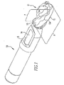
- Fig. 1 shows an inner tubular member 10 including a burr 11 having a body 12 with helical flutes 13 extending along the length of the body 12.
- the surface edges 13a of the flutes 13 incorporate parabolic wave patterns P along the entire lengths of the flutes 13.
- the burr 11 may have any number of flutes 13 and the flutes 13 may be located at any angle relative to a longitudinal axis passing through the burr 11.
- the flutes 13 may incorporate a pattern having an alternate geometry that may not be truly parabolic, but has the cutting characteristics of the parabolic wave pattern.
- a passageway 15 Located proximal to the burr 11 and between the inner tubular member 10 and the burr 11 is an opening 14 to a passageway 15 extending the length of the inner tubular member 10.
- the passageway 15 allows for the flow of fragmented tissue and bone during surgery.
- a vacuum (not shown) is attached to a proximal end (not shown) of the member 10 for vacuuming the tissue through the passageway 15.
- the parabolic wave patterns P on the flutes 13 provide the burr 11 with a more aggressive cutting action, especially when used in cutting bone, which causes the burr 11 to cut the bone into smaller fragments. Having smaller bone fragments allows the fragments to be removed more readily by the vacuum, thereby reducing the possibility of clogging and obscuring the visual image of the surgical area. Additionally, the parabolic wave pattern P deliberately creates inconsistencies in the burr geometry, thereby lessening any unpleasant harmonics or resonance of the burr device. This lessening, coupled with the fact the pattern P yields constant acceleration, provides the device with smoother cutting performance and controllability.
- Fig. 2 shows another inner tubular member 20 including a burr 21 having a body 22 with helical flutes 23 extending along the length of the body 22 and a tip 24 also having helical flutes 25.
- the tip 24 has a lower number of flutes 25 than the body 22. Having a lower number of flutes 25 on the tip 24 makes the tip 24 cut more aggressively than the body 22 because the individual cutting area of each flute 25 is more.
- Fig. 3 shows yet another inner tubular member 30 including a burr 31 having a body 32 with helical flutes 33 extending along the length of the body 32 and a tip 34 with helical flutes 35.
- the tip 34 of burr 31 has a higher number of flutes 35 than the body 32. Having a higher number of flutes 35 on the tip 34 makes the tip 34 cut less aggressively than the body 32 because the individual cutting area of each flute 35 is less.
- Having a transitional fluted burr with a different number of flutes on the tip than on the body provides more versatility to the user.
- the ability to perform different cutting techniques with one burr is more efficient than using two different devices. Additionally, it is more cost effective to use this type of burr due to only one burr having to be inventoried and utilized.
- Both burrs 21,31 are coupled to transition pieces 26,36 located between the inner tubular members 20,30 and the burrs 21,31.
- the transition pieces 26,36 include proximal portions 27,37 and tapered distal portions 28,38. In use, all of the members 10,20,30 would be disposed within an outer tubular member, as discussed above.
- the inner tubular members 10,20,30 and their components are made from metal material. However, other material strong enough to withstand the forces of a tissue cutting action may be used.
- the flutes, parabolic wave patterns on the flutes, and opening are made via a machining process or other process known to those of skill in the art.
Abstract
Description
- This application is a
PCT patent application claiming priority to US Patent Application No. 61/316860 US Patent Application No. 61/443301 - The present disclosure relates to arthroscopic resection devices for resection of tissue.
- Arthroscopic resection devices have been used in performing closed surgery, such as endoscopic surgery, i.e. arthroscopic surgery. Generally, these devices include, without limitation, blade devices and burr devices. Both the blade and burr devices include an elongate outer tubular member terminating at a distal end having an opening in the side wall and/or the end wall to form a cutting port or window. Both devices also include an elongate inner tubular member coaxially disposed in the outer tubular member and having a distal end disposed adjacent the port/window in the distal end of the outer tubular member. The distal end of the inner tubular member of the blade device has a surface or edge for engaging tissue via the port/window in the distal end of the outer tubular member and in many cases cooperates with the port/window to shear or cut tissue. Alternatively, the distal end of the inner tubular member of the of the burr device has a burr having helical grooved surfaces or flutes for drilling and grinding tissue via the port/window in the distal end of the outer tubular member and in many cases cooperates with the port/window to shear or cut tissue. The inner tubular members are rotatably driven at their proximal ends, normally via a hand piece having a small electric motor therein controlled by finger-actuated switches on the hand piece. A foot switch or switches on a console supply power to the hand piece.
- The helical flutes of the burr tend to not have any additional distinguishing geometrical features designed to enhance performance. They typically have smooth, non-serrated cutting edges and follow the design of end mills or drills. Additionally, the burrs tend to have the same number of flutes along the entire body of the burr. The surfaces or edges of the blade device inner member typically have straight cutting edges.
- The characteristics of these cutting features result in a less aggressive cutting action, thereby resecting the tissue or bone into larger fragments that increase the chances of the device becoming clogged, as well as cloud the image a surgeon has inside the surgical area. Additionally, these characteristics increase the possibility of the device displaying unpleasant harmonics or resonance during use. Furthermore, having the same number of flutes along the body of the burr allows for only one style of cutting, thereby providing the burr device with less versatility. Therefore, arthroscopic resection devices that alleviate these limitations are needed.
- In an aspect, the present disclosure relates to a resection device. The resection device includes an outer tubular member; and an inner tubular member disposed within the outer tubular member, the inner tubular member including a burr having a body with flutes extending along a length of the body, the flutes including parabolic wave patterns located along surface edges of the flutes. In an embodiment, the parabolic wave patterns extend along entire lengths of the flutes.
- In another aspect, the present disclosure relates to a resection device. The resection device includes an outer tubular member; and an inner tubular member disposed within the outer tubular member, the inner tubular member including a burr having a body with flutes extending along a length of the body and a tip with flutes, wherein the tip and the body include a different number of flutes. In an embodiment, the body has a higher number of flutes than the tip. In another embodiment, the body has a lower number of flutes than the tip.
- In yet another embodiment, the flutes on either the body or the tip include parabolic wave patterns located along surface edges of the flutes. In a further embodiment, the device further includes a transition piece located between the inner tubular member and the burr, the transition piece including a proximal portion and a tapered distal portion. In yet a further embodiment, the device further includes an opening located between the inner tubular member and the burr. In an embodiment, the opening leads to a passageway, the passageway extending along a length of the inner tubular member.
- In yet another aspect, the present disclosure relates to a resection device. The resection device includes an outer tubular member; and an inner tubular member disposed within the outer tubular member, the inner tubular member including a burr having a body with flutes extending along a length of the body and a tip with flutes, wherein the tip and the body include a different number of flutes, the flutes on either the body or the tip including parabolic wave patterns located along surface edges of the flutes.
- Further areas of applicability of the present disclosure will become apparent from the detailed description provided hereinafter. It should be understood that the detailed description and specific examples, while indicating the preferred embodiment of the disclosure, are intended for purposes of illustration only and are not intended to limit the scope of the disclosure.
- The accompanying drawings, which are incorporated in and form a part of the specification, illustrate the embodiments of the present disclosure and together with the written description serve to explain the principles, characteristics, and features of the disclosure. In the drawings:
-
Fig. 1 shows a first embodiment of an inner tubular member of the present disclosure. -
Fig. 2 shows a second embodiment of an inner tubular member of the present disclosure. -
Fig. 3 shows a third embodiment of an inner tubular member of the present disclosure. - The following description of the preferred embodiment(s) is merely exemplary in nature and is in no way intended to limit the disclosure, its application, or uses.
-
Figs. 1-3 show inner tubular members for use with burr devices and, specifically, the distal ends of the members.Fig. 1 shows an innertubular member 10 including aburr 11 having abody 12 withhelical flutes 13 extending along the length of thebody 12. Thesurface edges 13a of theflutes 13 incorporate parabolic wave patterns P along the entire lengths of theflutes 13. Theburr 11 may have any number offlutes 13 and theflutes 13 may be located at any angle relative to a longitudinal axis passing through theburr 11. Additionally, theflutes 13 may incorporate a pattern having an alternate geometry that may not be truly parabolic, but has the cutting characteristics of the parabolic wave pattern. - Located proximal to the
burr 11 and between the innertubular member 10 and theburr 11 is anopening 14 to apassageway 15 extending the length of the innertubular member 10. Thepassageway 15 allows for the flow of fragmented tissue and bone during surgery. A vacuum (not shown) is attached to a proximal end (not shown) of themember 10 for vacuuming the tissue through thepassageway 15. - The parabolic wave patterns P on the
flutes 13 provide theburr 11 with a more aggressive cutting action, especially when used in cutting bone, which causes theburr 11 to cut the bone into smaller fragments. Having smaller bone fragments allows the fragments to be removed more readily by the vacuum, thereby reducing the possibility of clogging and obscuring the visual image of the surgical area. Additionally, the parabolic wave pattern P deliberately creates inconsistencies in the burr geometry, thereby lessening any unpleasant harmonics or resonance of the burr device. This lessening, coupled with the fact the pattern P yields constant acceleration, provides the device with smoother cutting performance and controllability. -
Fig. 2 shows another innertubular member 20 including aburr 21 having abody 22 withhelical flutes 23 extending along the length of thebody 22 and atip 24 also havinghelical flutes 25. Thetip 24 has a lower number offlutes 25 than thebody 22. Having a lower number offlutes 25 on thetip 24 makes thetip 24 cut more aggressively than thebody 22 because the individual cutting area of eachflute 25 is more.Fig. 3 shows yet another innertubular member 30 including aburr 31 having abody 32 withhelical flutes 33 extending along the length of thebody 32 and atip 34 withhelical flutes 35. Unlikemember 20, thetip 34 ofburr 31 has a higher number offlutes 35 than thebody 32. Having a higher number offlutes 35 on thetip 34 makes thetip 34 cut less aggressively than thebody 32 because the individual cutting area of eachflute 35 is less. - Having a transitional fluted burr with a different number of flutes on the tip than on the body provides more versatility to the user. The ability to perform different cutting techniques with one burr is more efficient than using two different devices. Additionally, it is more cost effective to use this type of burr due to only one burr having to be inventoried and utilized.
- Any different number combination of flutes may be used on the
burrs flutes burr flutes flutes 13. The patterns may be located on the surface edges of theflutes flutes flutes - Both burrs 21,31 are coupled to transition
pieces tubular members burrs transition pieces proximal portions distal portions members - The inner
tubular members - As various modifications could be made to the exemplary embodiments, as described above with reference to the corresponding illustrations, without departing from the scope of the disclosure, it is intended that all matter contained in the foregoing description and shown in the accompanying drawings shall be interpreted as illustrative rather than limiting. Thus, the breadth and scope of the present disclosure should not be limited by any of the above-described exemplary embodiments, but should be defined only in accordance with the following claims appended hereto and their equivalents.
Claims (11)
- An arthroscopic resection device comprising:an outer tubular member; andan inner tubular member (10) disposed within the outer tubular member, the inner tubular member including an arthroscopic burr (11) having a body (12) with flutes (13) extending along a length of the body, the flutes including parabolic wave patterns (P) located along surface edges (13a) of the flutes.
- The arthroscopic resection device of claim 1 wherein the parabolic wave patterns extend along entire lengths of the flutes.
- The arthroscopic resection device of claim 1 or claim 2, wherein the burr (11) further comprises a tip with flutes, and wherein the tip and the body include a different number of flutes.
- The arthroscopic resection device of claim 3 wherein the body has a higher number of flutes than the tip.
- The arthroscopic resection device of claim 3 wherein the body has a lower number of flutes than the tip.
- The arthroscopic resection device of any one of claims 3 to 5 wherein the flutes on the tip include parabolic wave patterns located along surface edges of the flutes.
- The arthroscopic resection device of any one of the preceding claims wherein the device further includes a transition piece located between the inner tubular member and the arthroscopic burr, the transition piece including a proximal portion and a tapered distal portion.
- The arthroscopic resection device of any one of the preceding claims wherein the device further includes an opening (14) located between the inner tubular member and the arthroscopic burr.
- The arthroscopic resection device of claim 8 wherein the opening leads to a passageway (15), the passageway extending along a length of the inner tubular member.
- An arthroscopic resection device comprising:an outer tubular member; andan inner tubular member disposed within the outer tubular member, the inner tubular member including an arthroscopic burr having a body with flutes extending along a length of the body and a tip with flutes, wherein the tip and the body include a different number of flutes, the flutes on either the body or the tip including parabolic wave patterns located along surface edges of the flutes.
- The arthroscopic resection device of any one of the preceding claims wherein alternating flutes include the parabolic wave patterns located along surface edges of the flutes.
Applications Claiming Priority (4)
| Application Number | Priority Date | Filing Date | Title |
|---|---|---|---|
| US31686010P | 2010-03-24 | 2010-03-24 | |
| US201161443301P | 2011-02-16 | 2011-02-16 | |
| PCT/US2011/029708 WO2011119784A1 (en) | 2010-03-24 | 2011-03-24 | Arthroscopic resection devices |
| EP11714167.1A EP2549936B1 (en) | 2010-03-24 | 2011-03-24 | Arthroscopic resection devices |
Related Parent Applications (2)
| Application Number | Title | Priority Date | Filing Date |
|---|---|---|---|
| EP11714167.1A Division EP2549936B1 (en) | 2010-03-24 | 2011-03-24 | Arthroscopic resection devices |
| EP11714167.1A Division-Into EP2549936B1 (en) | 2010-03-24 | 2011-03-24 | Arthroscopic resection devices |
Publications (2)
| Publication Number | Publication Date |
|---|---|
| EP3138519A1 true EP3138519A1 (en) | 2017-03-08 |
| EP3138519B1 EP3138519B1 (en) | 2018-12-12 |
Family
ID=44657266
Family Applications (2)
| Application Number | Title | Priority Date | Filing Date |
|---|---|---|---|
| EP11714167.1A Not-in-force EP2549936B1 (en) | 2010-03-24 | 2011-03-24 | Arthroscopic resection devices |
| EP16190441.2A Active EP3138519B1 (en) | 2010-03-24 | 2011-03-24 | Arthroscopic resection devices |
Family Applications Before (1)
| Application Number | Title | Priority Date | Filing Date |
|---|---|---|---|
| EP11714167.1A Not-in-force EP2549936B1 (en) | 2010-03-24 | 2011-03-24 | Arthroscopic resection devices |
Country Status (8)
| Country | Link |
|---|---|
| US (3) | US20110238099A1 (en) |
| EP (2) | EP2549936B1 (en) |
| JP (1) | JP5871899B2 (en) |
| CN (1) | CN102892362B (en) |
| AU (1) | AU2011232446B2 (en) |
| BR (1) | BR112012024026A2 (en) |
| RU (1) | RU2556973C2 (en) |
| WO (1) | WO2011119784A1 (en) |
Cited By (1)
| Publication number | Priority date | Publication date | Assignee | Title |
|---|---|---|---|---|
| CH719484A1 (en) * | 2022-03-08 | 2023-09-15 | Swiss Medical Instr Ag | Method for producing an inner tube for a surgical cutting instrument. |
Families Citing this family (16)
| Publication number | Priority date | Publication date | Assignee | Title |
|---|---|---|---|---|
| US9232952B2 (en) | 2012-04-16 | 2016-01-12 | Medtronic Ps Medical, Inc. | Surgical bur with non-paired flutes |
| US9629646B2 (en) | 2012-07-11 | 2017-04-25 | Jens Kather | Curved burr surgical instrument |
| US9839441B2 (en) | 2013-03-14 | 2017-12-12 | Stryker Corporation | Surgical tool arrangement and surgical cutting accessory for use therewith |
| US9636131B2 (en) | 2013-03-15 | 2017-05-02 | Stryker Corporation | Surgical tool arrangement and surgical cutting accessory for use therewith |
| US9883873B2 (en) | 2013-07-17 | 2018-02-06 | Medtronic Ps Medical, Inc. | Surgical burs with geometries having non-drifting and soft tissue protective characteristics |
| US10335166B2 (en) | 2014-04-16 | 2019-07-02 | Medtronics Ps Medical, Inc. | Surgical burs with decoupled rake surfaces and corresponding axial and radial rake angles |
| US10470786B2 (en) | 2014-10-16 | 2019-11-12 | Stryker Corporation | Surgical tool arrangement and surgical cutting accessory for use therewith |
| US9955981B2 (en) | 2015-03-31 | 2018-05-01 | Medtronic Xomed, Inc | Surgical burs with localized auxiliary flutes |
| US10265082B2 (en) | 2015-08-31 | 2019-04-23 | Medtronic Ps Medical, Inc. | Surgical burs |
| GB201702404D0 (en) | 2017-02-14 | 2017-03-29 | Depuy Ireland Ultd Co | A surgical rotational cutting tool and method |
| WO2019028221A1 (en) | 2017-08-02 | 2019-02-07 | Stryker Corporation | Surgical tool systems, and methods of use thereof |
| USD878586S1 (en) * | 2017-09-07 | 2020-03-17 | G21 S.R.L. | Biomedical device |
| USD879293S1 (en) | 2017-09-07 | 2020-03-24 | G21 S.R.L. | Biomedical device |
| US11058480B2 (en) | 2018-04-27 | 2021-07-13 | RELIGN Corporation | Arthroscopic devices and methods |
| US20230000540A1 (en) * | 2019-12-19 | 2023-01-05 | RELIGN Corporation | Arthroscopic devices and methods |
| WO2023164094A1 (en) * | 2022-02-25 | 2023-08-31 | Life Spine, Inc. | Vertebral disc auger |
Citations (6)
| Publication number | Priority date | Publication date | Assignee | Title |
|---|---|---|---|---|
| DE19639193A1 (en) * | 1996-09-24 | 1998-04-16 | Aesculap Ag & Co Kg | Surgical milling cutter for bone or tissue |
| US5759185A (en) * | 1994-10-24 | 1998-06-02 | Smith & Nephew, Inc. | Surgical instrument |
| WO1998027876A1 (en) * | 1996-12-23 | 1998-07-02 | Smith & Nephew, Inc. | Surgical instrument |
| US6258093B1 (en) * | 1999-02-01 | 2001-07-10 | Garland U. Edwards | Surgical reamer cutter |
| WO2007142830A2 (en) * | 2006-06-01 | 2007-12-13 | Osteo Innovations, Llc | Vertebral treatment device , system and methods of use |
| US20080132929A1 (en) * | 2005-07-19 | 2008-06-05 | O'sullivan Denis F | Surgical bur with anti-chatter flute geometry |
Family Cites Families (15)
| Publication number | Priority date | Publication date | Assignee | Title |
|---|---|---|---|---|
| DE8418723U1 (en) | 1984-09-20 | Paul Meyer Chirurgische Instrumente, 5650 Solingen | Surgical knife | |
| US5047040A (en) * | 1987-11-05 | 1991-09-10 | Devices For Vascular Intervention, Inc. | Atherectomy device and method |
| RU2109490C1 (en) * | 1995-12-14 | 1998-04-27 | Государственное учреждение Научно-исследовательский институт травматологии и ортопедии ВСНЦ СО РАМН | Device for treating bone tissue |
| US6045305A (en) * | 1997-09-30 | 2000-04-04 | Plummer; Jerald D. | Helically fluted twist drill device |
| RU2125844C1 (en) * | 1998-06-04 | 1999-02-10 | Малыгина Марина Александровна | Guide for formation of canals for transplants of knee joint cruciate ligaments |
| US6579298B1 (en) * | 2000-02-29 | 2003-06-17 | Scimed Life Systems, Inc. | Method and apparatus for treating vein graft lesions |
| US6419684B1 (en) * | 2000-05-16 | 2002-07-16 | Linvatec Corporation | End-cutting shaver blade for axial resection |
| US20020090273A1 (en) * | 2001-01-10 | 2002-07-11 | Serwa Ronald K. | Roughing and finishing rotary tool apparatus and method |
| US7207752B2 (en) * | 2004-02-03 | 2007-04-24 | Star Cutter Company | Reamer and method for reaming |
| US8025662B2 (en) * | 2004-03-25 | 2011-09-27 | Symmetry Medical, Inc. | Bidirectional reaming cutter |
| JP4088271B2 (en) * | 2004-06-18 | 2008-05-21 | 日進工具株式会社 | Cutting tools |
| JP2010510042A (en) * | 2006-11-22 | 2010-04-02 | ソノマ・オーソペディック・プロダクツ・インコーポレイテッド | Tools for use in the placement of bone repair devices |
| DE102007025242B4 (en) | 2007-05-31 | 2014-07-31 | Gebr. Brasseler Gmbh & Co. Kg | Surgical instrument |
| US8460298B2 (en) * | 2007-08-15 | 2013-06-11 | Stryker Ireland Ltd. | Surgical bur with unequally spaced flutes, flutes with different rake angles and flutes with alternating reliefs |
| CA2759817A1 (en) | 2009-06-05 | 2010-12-09 | Entrigue Surgical, Inc. | Systems and devices for providing therapy of an anatomical structure |
-
2011
- 2011-03-24 RU RU2012144578/14A patent/RU2556973C2/en not_active IP Right Cessation
- 2011-03-24 WO PCT/US2011/029708 patent/WO2011119784A1/en active Application Filing
- 2011-03-24 US US13/070,584 patent/US20110238099A1/en not_active Abandoned
- 2011-03-24 JP JP2013501441A patent/JP5871899B2/en active Active
- 2011-03-24 BR BR112012024026A patent/BR112012024026A2/en not_active Application Discontinuation
- 2011-03-24 EP EP11714167.1A patent/EP2549936B1/en not_active Not-in-force
- 2011-03-24 CN CN201180015765.7A patent/CN102892362B/en active Active
- 2011-03-24 EP EP16190441.2A patent/EP3138519B1/en active Active
- 2011-03-24 AU AU2011232446A patent/AU2011232446B2/en active Active
-
2013
- 2013-04-10 US US13/860,464 patent/US9622756B2/en active Active
-
2017
- 2017-03-03 US US15/449,553 patent/US10537338B2/en active Active
Patent Citations (6)
| Publication number | Priority date | Publication date | Assignee | Title |
|---|---|---|---|---|
| US5759185A (en) * | 1994-10-24 | 1998-06-02 | Smith & Nephew, Inc. | Surgical instrument |
| DE19639193A1 (en) * | 1996-09-24 | 1998-04-16 | Aesculap Ag & Co Kg | Surgical milling cutter for bone or tissue |
| WO1998027876A1 (en) * | 1996-12-23 | 1998-07-02 | Smith & Nephew, Inc. | Surgical instrument |
| US6258093B1 (en) * | 1999-02-01 | 2001-07-10 | Garland U. Edwards | Surgical reamer cutter |
| US20080132929A1 (en) * | 2005-07-19 | 2008-06-05 | O'sullivan Denis F | Surgical bur with anti-chatter flute geometry |
| WO2007142830A2 (en) * | 2006-06-01 | 2007-12-13 | Osteo Innovations, Llc | Vertebral treatment device , system and methods of use |
Cited By (1)
| Publication number | Priority date | Publication date | Assignee | Title |
|---|---|---|---|---|
| CH719484A1 (en) * | 2022-03-08 | 2023-09-15 | Swiss Medical Instr Ag | Method for producing an inner tube for a surgical cutting instrument. |
Also Published As
| Publication number | Publication date |
|---|---|
| EP2549936A1 (en) | 2013-01-30 |
| CN102892362B (en) | 2016-08-24 |
| BR112012024026A2 (en) | 2016-08-30 |
| EP3138519B1 (en) | 2018-12-12 |
| US20130231670A1 (en) | 2013-09-05 |
| RU2556973C2 (en) | 2015-07-20 |
| EP2549936B1 (en) | 2017-01-25 |
| US9622756B2 (en) | 2017-04-18 |
| CN102892362A (en) | 2013-01-23 |
| US10537338B2 (en) | 2020-01-21 |
| US20170181754A1 (en) | 2017-06-29 |
| US20110238099A1 (en) | 2011-09-29 |
| AU2011232446A1 (en) | 2012-10-11 |
| JP5871899B2 (en) | 2016-03-01 |
| JP2013521992A (en) | 2013-06-13 |
| WO2011119784A1 (en) | 2011-09-29 |
| AU2011232446B2 (en) | 2016-02-04 |
| RU2012144578A (en) | 2014-04-27 |
Similar Documents
| Publication | Publication Date | Title |
|---|---|---|
| US10537338B2 (en) | Arthroscopic resection methods | |
| EP1667583B1 (en) | Surgical micro-burring instrument | |
| US9681913B2 (en) | Arthroscopic devices and methods | |
| US6419684B1 (en) | End-cutting shaver blade for axial resection | |
| EP2667794B1 (en) | Surgical cutting instrument with distal suction capabiilty | |
| KR101455091B1 (en) | Rotary Cutting Tool with Improved Cutting and Reduced Clogging on Soft Tissue and Thin Bone | |
| US20060229550A1 (en) | Liquid jet surgical instrument | |
| WO2004064651A3 (en) | Apparatus for making precise incisions in body vesseles | |
| JP2009543668A (en) | Endoscopic cutting instrument with axial and rotational movement | |
| DE60138291D1 (en) | ENDOSCOPIC STENCIL BLADES | |
| US10321929B2 (en) | Apparatus and method for cutting tissue | |
| US10080569B2 (en) | Shaped tip burr instrument | |
| KR20190042566A (en) | An incision assembly for a surgical instrument having a clog reduction tip | |
| EP1972288A1 (en) | Shaver blade with depth markings | |
| Becker | Technical considerations in powered instrumentation | |
| CN202342142U (en) | Combined type scalpel | |
| EP3510950B1 (en) | Nose knife | |
| CN219480261U (en) | Broken suction equipment with built-in electric rotary cutter |
Legal Events
| Date | Code | Title | Description |
|---|---|---|---|
| PUAI | Public reference made under article 153(3) epc to a published international application that has entered the european phase |
Free format text: ORIGINAL CODE: 0009012 |
|
| STAA | Information on the status of an ep patent application or granted ep patent |
Free format text: STATUS: THE APPLICATION HAS BEEN PUBLISHED |
|
| AC | Divisional application: reference to earlier application |
Ref document number: 2549936 Country of ref document: EP Kind code of ref document: P |
|
| AK | Designated contracting states |
Kind code of ref document: A1 Designated state(s): AL AT BE BG CH CY CZ DE DK EE ES FI FR GB GR HR HU IE IS IT LI LT LU LV MC MK MT NL NO PL PT RO RS SE SI SK SM TR |
|
| STAA | Information on the status of an ep patent application or granted ep patent |
Free format text: STATUS: REQUEST FOR EXAMINATION WAS MADE |
|
| 17P | Request for examination filed |
Effective date: 20170908 |
|
| RBV | Designated contracting states (corrected) |
Designated state(s): AL AT BE BG CH CY CZ DE DK EE ES FI FR GB GR HR HU IE IS IT LI LT LU LV MC MK MT NL NO PL PT RO RS SE SI SK SM TR |
|
| GRAP | Despatch of communication of intention to grant a patent |
Free format text: ORIGINAL CODE: EPIDOSNIGR1 |
|
| STAA | Information on the status of an ep patent application or granted ep patent |
Free format text: STATUS: GRANT OF PATENT IS INTENDED |
|
| RIC1 | Information provided on ipc code assigned before grant |
Ipc: A61B 17/32 20060101ALI20180620BHEP Ipc: A61B 17/16 20060101AFI20180620BHEP |
|
| INTG | Intention to grant announced |
Effective date: 20180710 |
|
| RIN1 | Information on inventor provided before grant (corrected) |
Inventor name: LORETH, BRIAN J. |
|
| GRAS | Grant fee paid |
Free format text: ORIGINAL CODE: EPIDOSNIGR3 |
|
| GRAA | (expected) grant |
Free format text: ORIGINAL CODE: 0009210 |
|
| STAA | Information on the status of an ep patent application or granted ep patent |
Free format text: STATUS: THE PATENT HAS BEEN GRANTED |
|
| AC | Divisional application: reference to earlier application |
Ref document number: 2549936 Country of ref document: EP Kind code of ref document: P |
|
| AK | Designated contracting states |
Kind code of ref document: B1 Designated state(s): AL AT BE BG CH CY CZ DE DK EE ES FI FR GB GR HR HU IE IS IT LI LT LU LV MC MK MT NL NO PL PT RO RS SE SI SK SM TR |
|
| REG | Reference to a national code |
Ref country code: GB Ref legal event code: FG4D |
|
| REG | Reference to a national code |
Ref country code: CH Ref legal event code: EP |
|
| REG | Reference to a national code |
Ref country code: AT Ref legal event code: REF Ref document number: 1074963 Country of ref document: AT Kind code of ref document: T Effective date: 20181215 |
|
| REG | Reference to a national code |
Ref country code: DE Ref legal event code: R096 Ref document number: 602011054884 Country of ref document: DE |
|
| REG | Reference to a national code |
Ref country code: IE Ref legal event code: FG4D |
|
| REG | Reference to a national code |
Ref country code: NL Ref legal event code: MP Effective date: 20181212 |
|
| REG | Reference to a national code |
Ref country code: LT Ref legal event code: MG4D |
|
| PG25 | Lapsed in a contracting state [announced via postgrant information from national office to epo] |
Ref country code: LV Free format text: LAPSE BECAUSE OF FAILURE TO SUBMIT A TRANSLATION OF THE DESCRIPTION OR TO PAY THE FEE WITHIN THE PRESCRIBED TIME-LIMIT Effective date: 20181212 Ref country code: ES Free format text: LAPSE BECAUSE OF FAILURE TO SUBMIT A TRANSLATION OF THE DESCRIPTION OR TO PAY THE FEE WITHIN THE PRESCRIBED TIME-LIMIT Effective date: 20181212 Ref country code: BG Free format text: LAPSE BECAUSE OF FAILURE TO SUBMIT A TRANSLATION OF THE DESCRIPTION OR TO PAY THE FEE WITHIN THE PRESCRIBED TIME-LIMIT Effective date: 20190312 Ref country code: HR Free format text: LAPSE BECAUSE OF FAILURE TO SUBMIT A TRANSLATION OF THE DESCRIPTION OR TO PAY THE FEE WITHIN THE PRESCRIBED TIME-LIMIT Effective date: 20181212 Ref country code: FI Free format text: LAPSE BECAUSE OF FAILURE TO SUBMIT A TRANSLATION OF THE DESCRIPTION OR TO PAY THE FEE WITHIN THE PRESCRIBED TIME-LIMIT Effective date: 20181212 Ref country code: NO Free format text: LAPSE BECAUSE OF FAILURE TO SUBMIT A TRANSLATION OF THE DESCRIPTION OR TO PAY THE FEE WITHIN THE PRESCRIBED TIME-LIMIT Effective date: 20190312 Ref country code: LT Free format text: LAPSE BECAUSE OF FAILURE TO SUBMIT A TRANSLATION OF THE DESCRIPTION OR TO PAY THE FEE WITHIN THE PRESCRIBED TIME-LIMIT Effective date: 20181212 |
|
| REG | Reference to a national code |
Ref country code: AT Ref legal event code: MK05 Ref document number: 1074963 Country of ref document: AT Kind code of ref document: T Effective date: 20181212 |
|
| PG25 | Lapsed in a contracting state [announced via postgrant information from national office to epo] |
Ref country code: RS Free format text: LAPSE BECAUSE OF FAILURE TO SUBMIT A TRANSLATION OF THE DESCRIPTION OR TO PAY THE FEE WITHIN THE PRESCRIBED TIME-LIMIT Effective date: 20181212 Ref country code: GR Free format text: LAPSE BECAUSE OF FAILURE TO SUBMIT A TRANSLATION OF THE DESCRIPTION OR TO PAY THE FEE WITHIN THE PRESCRIBED TIME-LIMIT Effective date: 20190313 Ref country code: AL Free format text: LAPSE BECAUSE OF FAILURE TO SUBMIT A TRANSLATION OF THE DESCRIPTION OR TO PAY THE FEE WITHIN THE PRESCRIBED TIME-LIMIT Effective date: 20181212 Ref country code: SE Free format text: LAPSE BECAUSE OF FAILURE TO SUBMIT A TRANSLATION OF THE DESCRIPTION OR TO PAY THE FEE WITHIN THE PRESCRIBED TIME-LIMIT Effective date: 20181212 |
|
| PG25 | Lapsed in a contracting state [announced via postgrant information from national office to epo] |
Ref country code: NL Free format text: LAPSE BECAUSE OF FAILURE TO SUBMIT A TRANSLATION OF THE DESCRIPTION OR TO PAY THE FEE WITHIN THE PRESCRIBED TIME-LIMIT Effective date: 20181212 |
|
| PG25 | Lapsed in a contracting state [announced via postgrant information from national office to epo] |
Ref country code: PT Free format text: LAPSE BECAUSE OF FAILURE TO SUBMIT A TRANSLATION OF THE DESCRIPTION OR TO PAY THE FEE WITHIN THE PRESCRIBED TIME-LIMIT Effective date: 20190412 Ref country code: IT Free format text: LAPSE BECAUSE OF FAILURE TO SUBMIT A TRANSLATION OF THE DESCRIPTION OR TO PAY THE FEE WITHIN THE PRESCRIBED TIME-LIMIT Effective date: 20181212 Ref country code: CZ Free format text: LAPSE BECAUSE OF FAILURE TO SUBMIT A TRANSLATION OF THE DESCRIPTION OR TO PAY THE FEE WITHIN THE PRESCRIBED TIME-LIMIT Effective date: 20181212 Ref country code: PL Free format text: LAPSE BECAUSE OF FAILURE TO SUBMIT A TRANSLATION OF THE DESCRIPTION OR TO PAY THE FEE WITHIN THE PRESCRIBED TIME-LIMIT Effective date: 20181212 |
|
| PG25 | Lapsed in a contracting state [announced via postgrant information from national office to epo] |
Ref country code: SK Free format text: LAPSE BECAUSE OF FAILURE TO SUBMIT A TRANSLATION OF THE DESCRIPTION OR TO PAY THE FEE WITHIN THE PRESCRIBED TIME-LIMIT Effective date: 20181212 Ref country code: EE Free format text: LAPSE BECAUSE OF FAILURE TO SUBMIT A TRANSLATION OF THE DESCRIPTION OR TO PAY THE FEE WITHIN THE PRESCRIBED TIME-LIMIT Effective date: 20181212 Ref country code: SM Free format text: LAPSE BECAUSE OF FAILURE TO SUBMIT A TRANSLATION OF THE DESCRIPTION OR TO PAY THE FEE WITHIN THE PRESCRIBED TIME-LIMIT Effective date: 20181212 Ref country code: IS Free format text: LAPSE BECAUSE OF FAILURE TO SUBMIT A TRANSLATION OF THE DESCRIPTION OR TO PAY THE FEE WITHIN THE PRESCRIBED TIME-LIMIT Effective date: 20190412 Ref country code: RO Free format text: LAPSE BECAUSE OF FAILURE TO SUBMIT A TRANSLATION OF THE DESCRIPTION OR TO PAY THE FEE WITHIN THE PRESCRIBED TIME-LIMIT Effective date: 20181212 |
|
| REG | Reference to a national code |
Ref country code: DE Ref legal event code: R097 Ref document number: 602011054884 Country of ref document: DE |
|
| PLBE | No opposition filed within time limit |
Free format text: ORIGINAL CODE: 0009261 |
|
| STAA | Information on the status of an ep patent application or granted ep patent |
Free format text: STATUS: NO OPPOSITION FILED WITHIN TIME LIMIT |
|
| PG25 | Lapsed in a contracting state [announced via postgrant information from national office to epo] |
Ref country code: MC Free format text: LAPSE BECAUSE OF FAILURE TO SUBMIT A TRANSLATION OF THE DESCRIPTION OR TO PAY THE FEE WITHIN THE PRESCRIBED TIME-LIMIT Effective date: 20181212 Ref country code: SI Free format text: LAPSE BECAUSE OF FAILURE TO SUBMIT A TRANSLATION OF THE DESCRIPTION OR TO PAY THE FEE WITHIN THE PRESCRIBED TIME-LIMIT Effective date: 20181212 Ref country code: AT Free format text: LAPSE BECAUSE OF FAILURE TO SUBMIT A TRANSLATION OF THE DESCRIPTION OR TO PAY THE FEE WITHIN THE PRESCRIBED TIME-LIMIT Effective date: 20181212 Ref country code: DK Free format text: LAPSE BECAUSE OF FAILURE TO SUBMIT A TRANSLATION OF THE DESCRIPTION OR TO PAY THE FEE WITHIN THE PRESCRIBED TIME-LIMIT Effective date: 20181212 |
|
| REG | Reference to a national code |
Ref country code: CH Ref legal event code: PL |
|
| 26N | No opposition filed |
Effective date: 20190913 |
|
| PG25 | Lapsed in a contracting state [announced via postgrant information from national office to epo] |
Ref country code: LU Free format text: LAPSE BECAUSE OF NON-PAYMENT OF DUE FEES Effective date: 20190324 |
|
| REG | Reference to a national code |
Ref country code: BE Ref legal event code: MM Effective date: 20190331 |
|
| PG25 | Lapsed in a contracting state [announced via postgrant information from national office to epo] |
Ref country code: IE Free format text: LAPSE BECAUSE OF NON-PAYMENT OF DUE FEES Effective date: 20190324 Ref country code: CH Free format text: LAPSE BECAUSE OF NON-PAYMENT OF DUE FEES Effective date: 20190331 Ref country code: LI Free format text: LAPSE BECAUSE OF NON-PAYMENT OF DUE FEES Effective date: 20190331 |
|
| PG25 | Lapsed in a contracting state [announced via postgrant information from national office to epo] |
Ref country code: BE Free format text: LAPSE BECAUSE OF NON-PAYMENT OF DUE FEES Effective date: 20190331 |
|
| PG25 | Lapsed in a contracting state [announced via postgrant information from national office to epo] |
Ref country code: TR Free format text: LAPSE BECAUSE OF FAILURE TO SUBMIT A TRANSLATION OF THE DESCRIPTION OR TO PAY THE FEE WITHIN THE PRESCRIBED TIME-LIMIT Effective date: 20181212 |
|
| PG25 | Lapsed in a contracting state [announced via postgrant information from national office to epo] |
Ref country code: MT Free format text: LAPSE BECAUSE OF NON-PAYMENT OF DUE FEES Effective date: 20190324 |
|
| PG25 | Lapsed in a contracting state [announced via postgrant information from national office to epo] |
Ref country code: CY Free format text: LAPSE BECAUSE OF FAILURE TO SUBMIT A TRANSLATION OF THE DESCRIPTION OR TO PAY THE FEE WITHIN THE PRESCRIBED TIME-LIMIT Effective date: 20181212 |
|
| PG25 | Lapsed in a contracting state [announced via postgrant information from national office to epo] |
Ref country code: HU Free format text: LAPSE BECAUSE OF FAILURE TO SUBMIT A TRANSLATION OF THE DESCRIPTION OR TO PAY THE FEE WITHIN THE PRESCRIBED TIME-LIMIT; INVALID AB INITIO Effective date: 20110324 |
|
| PG25 | Lapsed in a contracting state [announced via postgrant information from national office to epo] |
Ref country code: MK Free format text: LAPSE BECAUSE OF FAILURE TO SUBMIT A TRANSLATION OF THE DESCRIPTION OR TO PAY THE FEE WITHIN THE PRESCRIBED TIME-LIMIT Effective date: 20181212 |
|
| PGFP | Annual fee paid to national office [announced via postgrant information from national office to epo] |
Ref country code: FR Payment date: 20230208 Year of fee payment: 13 |
|
| PGFP | Annual fee paid to national office [announced via postgrant information from national office to epo] |
Ref country code: GB Payment date: 20230202 Year of fee payment: 13 Ref country code: DE Payment date: 20230125 Year of fee payment: 13 |
|
| P01 | Opt-out of the competence of the unified patent court (upc) registered |
Effective date: 20230525 |