EP2679174A1 - Medical instrument for severing tissue and cartilage - Google Patents
Medical instrument for severing tissue and cartilage Download PDFInfo
- Publication number
- EP2679174A1 EP2679174A1 EP13163333.1A EP13163333A EP2679174A1 EP 2679174 A1 EP2679174 A1 EP 2679174A1 EP 13163333 A EP13163333 A EP 13163333A EP 2679174 A1 EP2679174 A1 EP 2679174A1
- Authority
- EP
- European Patent Office
- Prior art keywords
- medical instrument
- outer shaft
- instrument according
- window
- curette
- Prior art date
- Legal status (The legal status is an assumption and is not a legal conclusion. Google has not performed a legal analysis and makes no representation as to the accuracy of the status listed.)
- Granted
Links
Images


Classifications
-
- A—HUMAN NECESSITIES
- A61—MEDICAL OR VETERINARY SCIENCE; HYGIENE
- A61B—DIAGNOSIS; SURGERY; IDENTIFICATION
- A61B17/00—Surgical instruments, devices or methods, e.g. tourniquets
- A61B17/16—Bone cutting, breaking or removal means other than saws, e.g. Osteoclasts; Drills or chisels for bones; Trepans
- A61B17/1604—Chisels; Rongeurs; Punches; Stamps
-
- A—HUMAN NECESSITIES
- A61—MEDICAL OR VETERINARY SCIENCE; HYGIENE
- A61B—DIAGNOSIS; SURGERY; IDENTIFICATION
- A61B17/00—Surgical instruments, devices or methods, e.g. tourniquets
- A61B17/16—Bone cutting, breaking or removal means other than saws, e.g. Osteoclasts; Drills or chisels for bones; Trepans
- A61B17/1659—Surgical rasps, files, planes, or scrapers
-
- A—HUMAN NECESSITIES
- A61—MEDICAL OR VETERINARY SCIENCE; HYGIENE
- A61B—DIAGNOSIS; SURGERY; IDENTIFICATION
- A61B17/00—Surgical instruments, devices or methods, e.g. tourniquets
- A61B17/32—Surgical cutting instruments
- A61B17/320016—Endoscopic cutting instruments, e.g. arthroscopes, resectoscopes
- A61B17/32002—Endoscopic cutting instruments, e.g. arthroscopes, resectoscopes with continuously rotating, oscillating or reciprocating cutting instruments
-
- A—HUMAN NECESSITIES
- A61—MEDICAL OR VETERINARY SCIENCE; HYGIENE
- A61B—DIAGNOSIS; SURGERY; IDENTIFICATION
- A61B17/00—Surgical instruments, devices or methods, e.g. tourniquets
- A61B17/32—Surgical cutting instruments
- A61B17/3205—Excision instruments
- A61B17/3207—Atherectomy devices working by cutting or abrading; Similar devices specially adapted for non-vascular obstructions
- A61B17/320708—Curettes, e.g. hollow scraping instruments
-
- A—HUMAN NECESSITIES
- A61—MEDICAL OR VETERINARY SCIENCE; HYGIENE
- A61B—DIAGNOSIS; SURGERY; IDENTIFICATION
- A61B10/00—Other methods or instruments for diagnosis, e.g. instruments for taking a cell sample, for biopsy, for vaccination diagnosis; Sex determination; Ovulation-period determination; Throat striking implements
- A61B10/02—Instruments for taking cell samples or for biopsy
- A61B10/0233—Pointed or sharp biopsy instruments
- A61B10/0266—Pointed or sharp biopsy instruments means for severing sample
-
- A—HUMAN NECESSITIES
- A61—MEDICAL OR VETERINARY SCIENCE; HYGIENE
- A61B—DIAGNOSIS; SURGERY; IDENTIFICATION
- A61B17/00—Surgical instruments, devices or methods, e.g. tourniquets
- A61B17/32—Surgical cutting instruments
- A61B17/3205—Excision instruments
- A61B17/3207—Atherectomy devices working by cutting or abrading; Similar devices specially adapted for non-vascular obstructions
- A61B17/320758—Atherectomy devices working by cutting or abrading; Similar devices specially adapted for non-vascular obstructions with a rotating cutting instrument, e.g. motor driven
-
- A—HUMAN NECESSITIES
- A61—MEDICAL OR VETERINARY SCIENCE; HYGIENE
- A61B—DIAGNOSIS; SURGERY; IDENTIFICATION
- A61B17/00—Surgical instruments, devices or methods, e.g. tourniquets
- A61B17/00234—Surgical instruments, devices or methods, e.g. tourniquets for minimally invasive surgery
- A61B2017/00353—Surgical instruments, devices or methods, e.g. tourniquets for minimally invasive surgery one mechanical instrument performing multiple functions, e.g. cutting and grasping
-
- A—HUMAN NECESSITIES
- A61—MEDICAL OR VETERINARY SCIENCE; HYGIENE
- A61B—DIAGNOSIS; SURGERY; IDENTIFICATION
- A61B17/00—Surgical instruments, devices or methods, e.g. tourniquets
- A61B17/32—Surgical cutting instruments
- A61B17/320016—Endoscopic cutting instruments, e.g. arthroscopes, resectoscopes
- A61B17/32002—Endoscopic cutting instruments, e.g. arthroscopes, resectoscopes with continuously rotating, oscillating or reciprocating cutting instruments
- A61B2017/320024—Morcellators, e.g. having a hollow cutting tube with an annular cutter for morcellating and removing tissue
-
- A—HUMAN NECESSITIES
- A61—MEDICAL OR VETERINARY SCIENCE; HYGIENE
- A61B—DIAGNOSIS; SURGERY; IDENTIFICATION
- A61B17/00—Surgical instruments, devices or methods, e.g. tourniquets
- A61B17/32—Surgical cutting instruments
- A61B17/3205—Excision instruments
- A61B17/3207—Atherectomy devices working by cutting or abrading; Similar devices specially adapted for non-vascular obstructions
- A61B17/320758—Atherectomy devices working by cutting or abrading; Similar devices specially adapted for non-vascular obstructions with a rotating cutting instrument, e.g. motor driven
- A61B2017/320775—Morcellators, impeller or propeller like means
Definitions
- the invention relates to a medical instrument for separating tissue and cartilage, having an outer shaft which has at least one window with at least one cutting edge in the region of its distal end, with an inner shaft which is received in the outer shaft and rotatable about its longitudinal axis Area of the window of the outer shaft, at least one opening having a cutting edge, which cooperates with the cutting at least one cutting edge of the outer shaft, wherein the hollow inner shaft is connected to a vacuum source.
- Such an instrument is, for example, from the EP 1 882 455 A1 known.
- Such instruments are used in minimally invasive surgery to sever tissue in the human or animal body.
- the distal end of the outer shaft is guided to the operating area in which the tissue to be separated is located.
- the inner shaft is rotated by means of an external or internal drive.
- the cutters formed on the inner shank cooperate in cutting with an edge of the window of the outer shank formed as a cutting edge, in which the edge of an opening of the inner shank passes by the edge of the window in the outer sheath during each revolution.
- the inner shaft is connectable to a vacuum source, the suction of which extends through the inner shaft to the window on the outer shaft to suck the tissue to be separated through the window into the shaft so that the blades can sever the tissue. Due to the negative pressure, the separated tissue is sucked through the hollow inner shaft and thus led away from the surgical site.
- ACD autologous chondrocyte transplantation
- a curette is a shaft-like instrument having at its distal end laterally projecting a circumferential cutting edge.
- the contour and the size of the cutting edge are chosen so that they can circle the defect.
- the curette is pressed into the cartilage tissue up to the level of the bone.
- In the center of the curette is an opening over which, by means of a spatula, which can be scraped and removed within the circumferential cutting edge of the curette tissue and cartilage parts. It can not be avoided that the so-called debridement, so separated cartilage pieces are released into the joint, which must then lead to a joint flushing to remove the small pieces, so-called chips.
- the diameter of the curette is then correspondingly large at a relatively large defect site.
- a scavenging with suction with the aid of a liquid jet directed from distal to proximal is from the WO 2004/037095 A2 known.
- the object is achieved in that on the outer shaft, in the region of the distal end, another window is recessed, which is surrounded by a curette.
- the instrument is formed at the distal end on one side as a shaver blade, through which the relatively soft pieces of tissue can be separated and sucked off, and at the same time is designed as a curette, which can be laid around a defect and in the Tissue, ie connective tissue and cartilage, can be pressed in up to the level of the bone.
- the separated from the curette relatively large tissue and cartilage pieces can be sucked through the additional window in the outer shaft towards the inner shaft and are there crushed by the rotating cutting edges of the openings in the inner shaft. Subsequently, these crushed pieces can be sucked into the interior of the inner shaft and removed. Therefore, the curette can define an area that is much larger than the diameter of the inner shaft. This therefore leads to no blockages, since the rotating inner shaft, the pieces of cartilage sucked through the curette in the region of the further window first crushed and only then the crushed pieces are sucked into the inner shaft.
- the instrument is first applied to the defect site in the area of the shaver blade window of the outer shaft, and the softer connective tissue and cartilage parts are separated and aspirated. Thereafter, the instrument only needs to be twisted so far about its longitudinal axis until the curette comes to rest over the defect site. This is then pressed into the cartilage tissue and separates the remaining cartilage pieces in the peripheral area within the curette. These are also sucked in, crushed and then removed. It is also possible to use the instrument only as a shaver blade or just as a curette.
- the curette Since the curette is located above the defect site and at least largely surrounds the defect site, and the separated cartilage pieces are aspirated in the direction of the rotating inner shaft, there is no risk that cartilage pieces will be released in the joint and then inevitably a joint irrigation be performed.
- the curette projects radially from an outer surface of the outer shaft.
- This measure has the advantage that this embodiment corresponds to that of a conventional curette, so that the surgeon can handle the instrument when the curette is used, as he is accustomed to when handling curettes as a single instrument. He can advance the instrument, usually even under visual control, to the defect site and, if he then rotates the curette to the surgical site, put it so that it circumnavigates the defect site and then by moving it laterally into the cartilage to the bone can impress.
- the contour of the curette viewed radially from the outside on the outer shaft, U-shaped.
- This measure has the advantage that when applying the curette to the defect site on the open side of the U in this inner area can still be viewed. This greatly facilitates the handling, especially the attachment to the defect site. It should be noted that bone surfaces, especially in the often occurring in the shoulder or knee joint defect sites are strongly curved. Such U- or horseshoe-shaped contour allows a targeted attachment to such a defect.
- the open end of the U-contour is on the proximal side.
- This measure has the advantage that when the instrument is brought to the defect site, the surgeon has an insight into the inner region of the curette from the proximal end to the distal end via the proximal open end, so that the latter can be targeted.
- curettes have a circular or oval closed peripheral cutting edge.
- the separating edge may lie in one plane or be curved accordingly.
- the separating edge of the curette lies in a plane. Since the operator has insight into the open end of the U in the defect site, he can then effectively depress the cutting edge of the curette by corresponding lateral tilting movements about the longitudinal axis of the shaft, even with curved surfaces. Effectively means that a very straight cutting edge is created at the periphery of the defect, which is an essential prerequisite for a good and rapid growth of a corresponding implant.
- the separating edge of the curette protrudes radially by a height which corresponds at least to the thickness of a cartilage layer to be separated.
- This measure has the advantage that the surgeon can press the curette laterally strong into the sometimes very tough cartilage tissue until it hits the bone surface. This ensures that all cartilage can be separated. If this height corresponds to the usual cartilaginous layers, it can also be ruled out that the separating edge is accidentally driven too far into the bone when strongly pressed, which is undesirable.
- the outer shaft has a single window, which is arranged diametrically opposite the curette.
- the window of the shaver blade in the outer shaft is formed by an obliquely cut from the proximal to the distal radially inwardly inclined section of the hollow outer shaft.
- This measure which is known per se, has the advantage that during the initial separation of the relatively soft connective tissue, the distal end of the outer shaft can be laid parallel to this oblique cut, so that then the inner rotating inner shaft can effectively separate this connective tissue.
- the inner shaft protrudes from the window in the region of the oblique section.
- This measure which is also known per se, has the advantage that, via these points of the shaver blade, the instrument can be pressed immovably into the tissue in the region of the window in the outer shaft.
- the rotatable inner shaft has a plurality of openings.
- the outer shaft has a coupling piece at the proximal end, through which the inner shaft can be guided proximally.
- the coupling piece makes it possible to connect the outer shaft to handle parts that can be gripped ergonomically by the hand of an operator. At the same time, this coupling piece serves as a guide for introducing the inner shaft into the outer shaft.
- the inner shaft at the proximal end of a connector, via which it is connectable to a vacuum source.
- a negative pressure source eg. Via a hose, can be connected to the inner shaft.
- this tube can be removed, so that the interior of the inner shaft can be cleaned accordingly.
- connection piece can be coupled via coupling elements with a drive which rotates the inner shaft about its longitudinal axis.
- This measure has the advantage that via these coupling elements, e.g. radially projecting coupling pin, easy to connect to the drive can be created, which rotates the inner shaft.
- a in the FIGS. 1 to 7 represented inventive medical instrument for separating tissue and cartilage is designated in its entirety by the reference numeral 10.
- the instrument 10 has an elongated straight hollow outer shaft 12.
- the first window 16 has a peripheral edge 18, which is designed as a cutting edge 20.
- jaws 22 From the cutting edge 20 are jaws 22 high, like that in particular Fig. 3 . 4 and 5 is apparent.
- the peripheral edge 18 is in the region of an oblique section 24, as in Fig. 4 is indicated.
- This oblique section 24 is inclined radially inward from the proximal to the distal, so that the first window 16 has an approximately oval cross-section.
- the inclination of the oblique cut 24 is, like that Fig. 4 It can be seen that at the distal vertex less than half of a diameter is cut off.
- the prongs 22 can be worked out.
- the inner shaft 32 is also formed as an elongated hollow shaft whose outer diameter corresponds approximately to the clear inner diameter of the outer shaft 12.
- the inner shaft 32 is circumferentially approximately evenly distributed with three openings 36, 37 and 38 provided.
- Each of the openings 36, 37 and 38 is provided at its peripheral edge with a peripheral cutting edge 40, wherein only the cutting edge 40 of the opening 36 is provided with a reference numeral.
- the length of the inner shaft 32 is selected so that it can be pushed completely into the outer shaft 12 from the proximal end.
- the cutting edges 40 of the openings 36 etc. rotate with and run on the also formed as a cutting edge 20 edge 18 of the first window 16 in the outer shaft 12 over. This scissors cuts then take place.
- the inner shaft 32 has a connecting piece 42, via which the inner shaft 32 can be connected to a vacuum source 44, as in FIG Fig. 1 is indicated.
- connecting piece 42 still radially projecting coupling pin 46, via which a coupling piece of a drive not shown here can be brought, through which the inner shaft 32 can be rotated in the outer shaft 12.
- the outer shaft 12 has a coupling piece 26 at its proximal end.
- the inner shaft 32 can be pushed so far from the proximal to the distal through the coupling piece 26 until the connecting piece 42 has fit inside the sleeve-like body of the coupling piece 26, as is the case Fig. 1 is apparent. As a result, the inner shaft 32 is guided and received in the outer shaft 12.
- the distal region of the instrument 10 operates as a so-called "shaver blade”.
- the inner shaft 32 When rotating the inner shaft 32 separate the cutting edges 40 of the openings 36, 37, 38 in cooperation with the cutting edge 20 of the first window 16 in the outer shaft corresponding tissue pieces and they are sucked into the interior of the inner shaft 32 through the openings 36, 37, 38 and dissipated.
- the negative pressure ensures that the tissue parts to be separated are sucked laterally against the first window 16 in the outer shaft 12 and then separated.
- This further window 50 is surrounded by a curette 52 which has the contour 54 of a proximally open U '.
- the radially outer U-edge is formed as a sharp separating edge 56. As in particular from 4 and 5 can be seen, this separating edge 56 projects laterally beyond the outer surface 58 of the outer shaft 12.
- cartilage pieces even relatively large pieces of cartilage, are now separated from the separating edge 56, they are moved by the negative pressure source 44 through the further window 50 in the direction of the interior of the outer shaft 12 and then by the rotating cutting edges 40 of the openings 36, 37 and 38 in FIG Interior shaft cut into the smallest pieces. If these pieces are then sufficiently small, they can be sucked and discharged via the openings 36, 37 and 38 in the inner shaft 32.
- the separating edge 56 may be formed as a closed oval around the oval window 50 circumferential edge.
- this separating edge 56 is open to the proximal end.
- the surgeon can, for example, first push the distally closed region of the separating edge 56 against the defect site and position it so that it comes to rest somewhat behind the area of the defect site seen by the surgeon and surrounds this region. Then he can gradually press the separating edge 56 into the cartilaginous tissue. He can at least partially see this via the proximal end open end 59 of the profile.
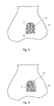
- Fig. 8 is shown very schematically a femur 70 in the region of a knee joint.
- defect 71 which was first processed with the "Shaver Blade" of the instrument 10.
- a relatively blurred peripheral edge 72 is formed on the surrounding tissue of the bone 70.
- the bone material 74 is already exposed.
- Fig. 9 now shows the defect 71 after the curette 52 has been applied, pressed in and the marginal cartilage tissue has been removed down to the bone material 74.
- the smooth and sharp separating edge 56 of the curette 52 produced a sharp edge 76, which protrudes at approximately the right angle from the bone surface and corresponds to its geometry.
- the contour 54 of the separating edge 56 of the curette can also be closed, oval or round.
- the surface of the separating edge can also run correspondingly curved if such defects occur at extremely curved bone sites, so that then the contour of the curette or its separating edge 56 can already be adapted to this bone contour.
Abstract
Description
Die Erfindung betrifft ein medizinisches Instrument zum Abtrennen von Gewebe und Knorpel, mit einem Außenschaft, der im Bereich seines distalen Endes zumindest ein Fenster mit zumindest einer Schneide aufweist, mit einem im Außenschaft aufgenommenen um seine Längsachse rotierbaren Innenschaft, der an seinem distalen Ende, im Bereich des Fensters des Außenschafts, zumindest eine Öffnung mit einer Schneide aufweist, die mit der zumindest einen Schneide des Außenschaftes schneidend zusammenwirkt, wobei der hohle Innenschaft an eine Unterdruckquelle anschließbar ist.The invention relates to a medical instrument for separating tissue and cartilage, having an outer shaft which has at least one window with at least one cutting edge in the region of its distal end, with an inner shaft which is received in the outer shaft and rotatable about its longitudinal axis Area of the window of the outer shaft, at least one opening having a cutting edge, which cooperates with the cutting at least one cutting edge of the outer shaft, wherein the hollow inner shaft is connected to a vacuum source.
Ein derartiges Instrument ist bspw. aus der
Derartige Instrumente werden in der minimal-invasiven Chirurgie zum Abtrennen von Gewebe im menschlichen oder tierischen Körper verwendet. Dazu wird das distale Ende des Außenschafts zu dem Operationsgebiet geführt, in dem sich das abzutrennende Gewebe befindet. Zum Abtrennen des Gewebes wird der Innenschaft mittels eines externen oder internen Antriebes in Rotation versetzt. Die am Innenschaft ausgebildeten Schneiden wirken beim Umlaufen mit einem als Schneide ausgebildeten Rand des Fensters des Außenschaftes schneidend zusammen, in dem die Schneide einer Öffnung des Innenschafts an der Schneide des Fensters im Außenschaft bei jedem Umlauf vorbeiläuft. Um das abzutrennende Gewebe zwischen die zusammenwirkenden Schneiden zu bringen, ist der Innenschaft mit einer Unterdruckquelle verbindbar, deren Saugwirkung durch den Innenschaft bis hin zu dem Fenster am Außenschaft reicht, um das abzutrennende Gewebe durch das Fenster in den Schaft zu saugen, so dass die Schneiden das Gewebe abtrennen können. Durch den Unterdruck wird das abgetrennte Gewebe durch den hohlen Innenschaft abgesaugt und somit von der Operationsstelle weggeführt.Such instruments are used in minimally invasive surgery to sever tissue in the human or animal body. For this purpose, the distal end of the outer shaft is guided to the operating area in which the tissue to be separated is located. To separate the tissue, the inner shaft is rotated by means of an external or internal drive. The cutters formed on the inner shank cooperate in cutting with an edge of the window of the outer shank formed as a cutting edge, in which the edge of an opening of the inner shank passes by the edge of the window in the outer sheath during each revolution. To bring the tissue to be separated between the cooperating blades, the inner shaft is connectable to a vacuum source, the suction of which extends through the inner shaft to the window on the outer shaft to suck the tissue to be separated through the window into the shaft so that the blades can sever the tissue. Due to the negative pressure, the separated tissue is sucked through the hollow inner shaft and thus led away from the surgical site.
Insbesondere in der Arthroskopie liegen unter dem Hautgewebe relativ feste Knorpelbereiche, die bei Knorpeldefekten bis auf den Knochen hin entfernt werden müssen.Especially in arthroscopy, there are relatively firm cartilage areas under the skin tissue, which must be removed in case of cartilage defects down to the bone.
Bei der sog. Autologen Chondrozyten-Transplantation (ACD) zur Regenerierung eines Knorpels, ist es erforderlich, die Defektränder äußerst scharf abzugrenzen. Dies ist deswegen notwendig, damit ein an die Defektstelle verbrachtes Implantat an diesen Defekträndern nachhaltig anwachsen kann.In the so-called autologous chondrocyte transplantation (ACD) for the regeneration of a cartilage, it is necessary to demarcate the defect edges extremely sharply. This is therefore necessary so that an implant spent at the defect site can sustainably grow at these defect edges.
Mit dem eingangs erwähnten Instrument können keine solchen scharfen Defektränder bewerkstelligt werden und es wurde auch festgestellt, dass Knorpel bis hin auf die Knochenfläche nicht vollständig entfernt werden können.With the instrument mentioned above, no such sharp defect edges can be accomplished and it has also been found that cartilage can not be completely removed down to the bone surface.
Daher wird dann ein weiteres Instrument herangezogen, nämlich eine sog. Kürette.Therefore, another instrument is used, namely a so-called curette.
Eine Kürette ist ein schaftartiges Instrument, das an seinem distalen Ende seitlich vorstehend eine umlaufende Schneidekante aufweist. Die Kontur und die Größe der Schneidekante werden so gewählt, dass diese die Defektstelle umrunden kann. Die Kürette wird in das Knorpelgewebe bis auf Höhe des Knochens eingedrückt. Mittig ist in der Kürette eine Öffnung über die, mittels eines Spatels, die innerhalb der umlaufenden Schneidekante der Kürette abgetrennten Gewebe- und Knorpelteile abgeschabt und entfernt werden können. Dabei lässt sich nicht vermeiden, dass das sog. Debridement, also abgetrennte Knorpelstücke ins Gelenk freigesetzt werden, was anschließend zu einer Gelenkspülung zur Entfernung der kleinen Stücke, sog. Chips, führen muss. Der Durchmesser der Kürette ist bei einer relativ großen Defektstelle dann entsprechend groß.A curette is a shaft-like instrument having at its distal end laterally projecting a circumferential cutting edge. The contour and the size of the cutting edge are chosen so that they can circle the defect. The curette is pressed into the cartilage tissue up to the level of the bone. In the center of the curette is an opening over which, by means of a spatula, which can be scraped and removed within the circumferential cutting edge of the curette tissue and cartilage parts. It can not be avoided that the so-called debridement, so separated cartilage pieces are released into the joint, which must then lead to a joint flushing to remove the small pieces, so-called chips. The diameter of the curette is then correspondingly large at a relatively large defect site.
Es wurden schon Versuche dahingehend gemacht, eine solche Kürette als Saugkürette auszubilden. Dann müssen aber die von der Kürette abgetrennten Knorpelstücke immer kleiner sein als der Saugquerschnitt des Instrumentes, da ansonsten der Saugquerschnitt durch die Knorpelstücke verstopft. Dementsprechend müsste dann der Absaugkanal einen entsprechend großen Durchmesser aufweisen, was bei Defektstellen mit Durchmessern von einigen Zentimetern nicht durchführbar ist, da ein solch großer Raum nicht bei Gelenkoperationen zur Verfügung steht.There have been attempts made to form such a curette as a suction curette. Then, however, the cartilage pieces separated from the curette must always be smaller than the suction cross-section of the instrument, since otherwise the suction cross-section becomes blocked by the cartilage pieces. Accordingly, then the suction would have a correspondingly large diameter, which is not feasible at defect sites with diameters of a few centimeters, since such a large space is not available for joint operations.
Eine Kürette mit Absaugung unter Zuhilfenahme eines von distal nach proximal gerichteten Flüssigkeitsstrahles ist aus der
Wie eingangs erwähnt, werden diese Eingriffe meist minimal-invasiv durchgeführt. Es müssen nacheinander zwei unterschiedliche Instrumente der Operationsstelle zugeführt werden, zunächst die eingangs erwähnte Vorrichtung, ein sog. Shaver-Blade und anschließend eine Kürette gefolgt von einer Gelenkspülung.As mentioned above, these interventions are usually performed minimally invasive. It must be supplied successively two different instruments of the surgical site, first the device mentioned above, a so-called. Shaver blade and then a curette followed by a joint lavage.
Es ist daher Aufgabe der vorliegenden Erfindung hier Abhilfe zu schaffen und ein medizinisches Instrument zum Abtrennen von Gewebe und Knorpel zu entwickeln, das einfacher und effektiver zum Abtrennen von Gewebe und Knorpel einsetzbar ist.It is therefore an object of the present invention to remedy this situation and to develop a medical instrument for separating tissue and cartilage, which can be used more easily and effectively for separating tissue and cartilage.
Erfindungsgemäß wird die Aufgabe dadurch gelöst, dass am Außenschaft, im Bereich des distalen Endes, ein weiteres Fenster ausgespart ist, das von einer Kürette umgeben ist.According to the invention the object is achieved in that on the outer shaft, in the region of the distal end, another window is recessed, which is surrounded by a curette.
Diese Maßnahme hat nun den Vorteil, dass das Instrument am distalen Ende auf einer Seite als Shaver-Blade ausgebildet ist, durch das die relativ weichen Gewebestücke abgetrennt und abgesaugt werden können, und zugleich als Kürette ausgebildet ist, die um eine Defektstelle legbar und in das Gewebe, also Bindegewebe und Knorpel, bis auf Höhe des Knochens eindrückbar ist. Die von der Kürette abgetrennten relativ großen Gewebe- und Knorpelstücke können durch das weitere Fenster im Außenschaft in Richtung Innenschaft gesaugt werden und werden dort von den rotierenden Schneidekanten der Öffnungen im Innenschaft zerkleinert. Anschließend können diese zerkleinerten Stücke in den Innenraum des Innenschafts eingesaugt und abgeführt werden. Daher kann die Kürette einen Bereich umgrenzen, der wesentlich größer ist als der Durchmesser des Innenschaftes ist. Dies führt deswegen zu keinen Verstopfungen, da der rotierende Innenschaft, die durch die Kürette abgesaugten Knorpelstücke im Bereich des weiteren Fensters zunächst zerkleinert und erst dann die zerkleinerten Stücke in den Innenschaft eingesaugt werden.This measure now has the advantage that the instrument is formed at the distal end on one side as a shaver blade, through which the relatively soft pieces of tissue can be separated and sucked off, and at the same time is designed as a curette, which can be laid around a defect and in the Tissue, ie connective tissue and cartilage, can be pressed in up to the level of the bone. The separated from the curette relatively large tissue and cartilage pieces can be sucked through the additional window in the outer shaft towards the inner shaft and are there crushed by the rotating cutting edges of the openings in the inner shaft. Subsequently, these crushed pieces can be sucked into the interior of the inner shaft and removed. Therefore, the curette can define an area that is much larger than the diameter of the inner shaft. This therefore leads to no blockages, since the rotating inner shaft, the pieces of cartilage sucked through the curette in the region of the further window first crushed and only then the crushed pieces are sucked into the inner shaft.
Beim operativen Eingriff wird das Instrument zunächst im Bereich des Shaver-Blade-Fensters des Außenschaftes an die Defektstelle angelegt und es werden die weicheren Bindegewebs- und Knorpelteile abgetrennt und abgesaugt. Danach braucht das Instrument nur soweit um dessen Längsachse verdreht werden, bis die Kürette über der Defektstelle zum Liegen kommt. Diese wird dann in das Knorpelgewebe eingedrückt und trennt die noch verbleibenden Knorpelstücke im Umfangsbereich innerhalb der Kürette ab. Diese werden ebenfalls angesaugt, zerkleinert und dann abgeführt. Es ist auch möglich, das Instrument nur als Shaver-Blade oder nur als Kürette einzusetzen. Da die Kürette über der Defektstelle liegt und die Defektstelle zumindest größtenteils umrundet, und die abgetrennten Knorpelstücke in Richtung des rotierenden Innenschafts abgesaugt werden, besteht nicht die Gefahr, dass Knorpelstücke im Gelenk freigesetzt werden und dann zwangsläufig eine Gelenkspülung durchgeführt werden muss.During surgery, the instrument is first applied to the defect site in the area of the shaver blade window of the outer shaft, and the softer connective tissue and cartilage parts are separated and aspirated. Thereafter, the instrument only needs to be twisted so far about its longitudinal axis until the curette comes to rest over the defect site. This is then pressed into the cartilage tissue and separates the remaining cartilage pieces in the peripheral area within the curette. These are also sucked in, crushed and then removed. It is also possible to use the instrument only as a shaver blade or just as a curette. Since the curette is located above the defect site and at least largely surrounds the defect site, and the separated cartilage pieces are aspirated in the direction of the rotating inner shaft, there is no risk that cartilage pieces will be released in the joint and then inevitably a joint irrigation be performed.
Somit wird nicht nur der Einsatz von zwei verschiedenen Geräten vermieden, die nacheinander eingeschoben und von der Operationsstelle entfernt werden müssen, sondern es kann auch die Knochenspülung weggelassen werden.Thus, not only the use of two different devices is avoided, which must be successively inserted and removed from the surgical site, but it can also be the bone rinse be omitted.
Bei sehr kleinen Knorpelteilen, bspw. bei einer Defektstelle im Knie, besteht immer die Gefahr, dass die Knorpelteile auch bei einem Spülvorgang nicht vollständig abgespült, sondern irgendwo im Kniegelenk zwischen die beiden aneinanderliegenden Knochen von Ober- und Unterschenkel hängenbleiben. Somit ist das Instrument einfacher zu handhaben und auch die damit durchgeführten Vorgänge sind für den Patienten wesentlich atraumatischer und im Ergebnis sicherer durchführbar.In the case of very small cartilage parts, for example in the case of a defect in the knee, there is always the danger that the cartilage parts will not be completely rinsed off even during a rinsing operation, but will get stuck somewhere in the knee joint between the two adjoining bones of the thigh and lower leg. Thus, the instrument is easier to handle and also the processes performed with it are much more atraumatic for the patient and in the result safer feasible.
In einer weiteren Ausgestaltung der Erfindung steht die Kürette von einer Außenfläche des Außenschafts radial vor.In a further embodiment of the invention, the curette projects radially from an outer surface of the outer shaft.
Diese Maßnahme hat den Vorteil, dass diese Ausgestaltung dem einer üblichen Kürette entspricht, so dass der Operateur das Instrument, wenn dessen Kürette zum Einsatz kommt, so handhaben kann, wie er das beim Handhaben von Küretten als Einzelinstrument gewohnt ist. Er kann das Instrument, meist sogar unter Sichtkontrolle, bis an die Defektstelle vorschieben und, wenn er dann die Kürette zur Operationsstelle hindreht, diese so anlegen, dass sie die Defektstelle entsprechend umrundet und dann durch ein seitliches Bewegen diese in den Knorpel bis auf den Knochen eindrücken kann.This measure has the advantage that this embodiment corresponds to that of a conventional curette, so that the surgeon can handle the instrument when the curette is used, as he is accustomed to when handling curettes as a single instrument. He can advance the instrument, usually even under visual control, to the defect site and, if he then rotates the curette to the surgical site, put it so that it circumnavigates the defect site and then by moving it laterally into the cartilage to the bone can impress.
In einer weiteren Ausgestaltung der Erfindung ist die Kontur der Kürette, radial von außen auf den Außenschaft gesehen, U-förmig.In a further embodiment of the invention, the contour of the curette, viewed radially from the outside on the outer shaft, U-shaped.
Diese Maßnahme hat den Vorteil, dass beim Ansetzen der Kürette an die Defektstelle über die offene Seite des U in diesen inneren Bereich noch eingesehen werden kann. Das erleichtert erheblich die Handhabung, insbesondere das Ansetzen an der Defektstelle. Dabei ist zu berücksichtigen, dass Knochenoberflächen, insbesondere bei den häufig in Schulter- oder Kniegelenk vorkommenden Defektstellen, stark gekrümmt sind. Eine solche U- oder hufeisenförmige Kontur erlaubt ein zielgerechtes Ansetzen an einer solchen Defektstelle.This measure has the advantage that when applying the curette to the defect site on the open side of the U in this inner area can still be viewed. This greatly facilitates the handling, especially the attachment to the defect site. It should be noted that bone surfaces, especially in the often occurring in the shoulder or knee joint defect sites are strongly curved. Such U- or horseshoe-shaped contour allows a targeted attachment to such a defect.
In einer weiteren Ausgestaltung der Erfindung liegt das offene Ende der U-Kontur proximalseitig.In a further embodiment of the invention, the open end of the U-contour is on the proximal side.
Diese Maßnahme hat den Vorteil, dass der Operateur beim Heranführen des Instrumentes an die Defektstelle von proximal nach distal blickend in den inneren Bereich der Kürette über das proximalseitig offene Ende Einblick hat, somit diese zielgerecht ansetzen kann.This measure has the advantage that when the instrument is brought to the defect site, the surgeon has an insight into the inner region of the curette from the proximal end to the distal end via the proximal open end, so that the latter can be targeted.
Wie zuvor erwähnt, weisen die meisten Küretten eine kreisförmige oder ovale geschlossene umlaufende Trennkante auf. Je nach Ausgestaltung und Einsatzgebiet, kann die Trennkante in einer Ebene liegen oder entsprechend gekrümmt sein.As previously mentioned, most curettes have a circular or oval closed peripheral cutting edge. Depending on the design and field of application, the separating edge may lie in one plane or be curved accordingly.
In Zusammenhang mit der U-Struktur ist von Vorteil, wenn die Trennkante der Kürette in einer Ebene liegt. Da der Operateur Einsicht über das offene Ende des U in die Defektstelle hat, kann er dann die Trennkante der Kürette durch entsprechende seitliche Kippbewegungen um die Längsachse des Schaftes entsprechend auch bei gekrümmten Oberflächen effektiv eindrücken. Effektiv bedeutet, dass eine sehr gerade Schnittkante am Umfang des Defektes entsteht, die eine wesentliche Voraussetzung für ein gutes und rasches Anwachsen eines entsprechenden Implantates ist.In connection with the U-structure is advantageous if the separating edge of the curette lies in a plane. Since the operator has insight into the open end of the U in the defect site, he can then effectively depress the cutting edge of the curette by corresponding lateral tilting movements about the longitudinal axis of the shaft, even with curved surfaces. Effectively means that a very straight cutting edge is created at the periphery of the defect, which is an essential prerequisite for a good and rapid growth of a corresponding implant.
In einer weiteren Ausgestaltung der Erfindung steht die Trennkante der Kürette um eine solche Höhe radial vor, die zumindest der Dicke einer abzutrennenden Knorpelschicht entspricht.In a further embodiment of the invention, the separating edge of the curette protrudes radially by a height which corresponds at least to the thickness of a cartilage layer to be separated.
Diese Maßnahme hat den Vorteil, dass der Operateur die Kürette seitlich kräftig in das manchmal sehr zähe Knorpelgewebe eindrücken kann, bis er auf die Knochenoberfläche trifft. Dadurch ist sichergestellt, dass sämtlicher Knorpel abgetrennt werden kann. Entspricht diese Höhe den üblichen Knorpelschichten kann auch ausgeschlossen werden, dass die Trennkante bei starkem Drücken versehentlich zu weit in den Knochen eingetrieben wird, was unerwünscht ist.This measure has the advantage that the surgeon can press the curette laterally strong into the sometimes very tough cartilage tissue until it hits the bone surface. This ensures that all cartilage can be separated. If this height corresponds to the usual cartilaginous layers, it can also be ruled out that the separating edge is accidentally driven too far into the bone when strongly pressed, which is undesirable.
In einer weiteren Ausgestaltung der Erfindung weist der Außenschaft ein einziges Fenster auf, das diametral gegenüberliegend zur Kürette angeordnet ist.In a further embodiment of the invention, the outer shaft has a single window, which is arranged diametrically opposite the curette.
Dies hat den Vorteil, dass bei relativ dünnen Schäften das einzige Fenster des Shaver-Blades dann relativ groß ausgebildet werden kann, so dass die Stabilität des Schaftes in diesem distalen Endbereich durch dieses Fenster nicht so geschwächt wird, dass dann beim Eintreiben der Kürette Verformungen auftreten. Dadurch, dass das nur eine Fenster diametral gegenüberliegend zur Kürette ist, verbleiben zwischen diesem einen Fenster des Shaver-Blades und dem weiteren Fenster im Bereich der Kürette ausreichende Materialstege, um die Stabilität aufrechtzuerhalten. Außerdem gibt es dem Operateur ein gutes Gefühl, dass er nach dem ersten Operationsabschnitt mit dem Shaver-Blade den Außenschaft gerade um 180° drehen muss, um dann die Kürette einsatzbereit an die Defektstelle bringen zu können. Dies erleichtert die Handhabung.This has the advantage that with relatively thin shanks the single window of the shaver blade can then be made relatively large, so that the stability of the shank in this distal end region is not weakened by this window, so that deformations occur when the curette is driven in , Due to the fact that only one window is diametrically opposite the curette, sufficient material webs remain between this one window of the shaver blade and the further window in the region of the curette in order to maintain the stability. In addition, it gives the operator a good feeling that after the first surgical session with the shaver blade, he has to turn the outer shaft 180 ° in order to be able to bring the curette ready for use to the defect site. This facilitates handling.
In einer weiteren Ausgestaltung der Erfindung ist das Fenster des Shaver-Blades im Außenschaft durch einen von proximal nach distal radial nach innen geneigten Schrägschnitt des hohlen Außenschaftes ausgebildet.In a further embodiment of the invention, the window of the shaver blade in the outer shaft is formed by an obliquely cut from the proximal to the distal radially inwardly inclined section of the hollow outer shaft.
Diese an sich bekannte Maßnahme hat den Vorteil, dass beim ausgänglichen Abtrennen des relativ weichen Bindegewebes, das distale Ende des Außenschaftes parallel zu diesem Schrägschnitt angelegt werden kann, so dass dann der innere rotierende Innenschaft effektiv dieses Bindegewebe abtrennen kann.This measure, which is known per se, has the advantage that during the initial separation of the relatively soft connective tissue, the distal end of the outer shaft can be laid parallel to this oblique cut, so that then the inner rotating inner shaft can effectively separate this connective tissue.
Dazu ist von Vorteil, dass der Innenschaft im Bereich des Schrägschnittes aus dem Fenster ragt.It is advantageous that the inner shaft protrudes from the window in the region of the oblique section.
Dies erlaubt besonders effizientes Abtrennen des Bindegewebes.This allows particularly efficient separation of the connective tissue.
In einer weiteren Ausgestaltung der Erfindung weist die Umfangskante des Fensters des Außenschafts von dieser hochstehende Zacken auf.In a further embodiment of the invention, the peripheral edge of the window of the outer shaft of this upstanding teeth.
Diese ebenfalls an sich bekannte Maßnahme hat den Vorteil, dass über diese Zacken des Shaver-Blades, das Instrument im Bereich des Fensters im Außenschaft unverrückbar in das Gewebe eingedrückt werden kann.This measure, which is also known per se, has the advantage that, via these points of the shaver blade, the instrument can be pressed immovably into the tissue in the region of the window in the outer shaft.
In einer weiteren Ausgestaltung der Erfindung weist der rotierbare Innenschaft mehrere Öffnungen auf.In a further embodiment of the invention, the rotatable inner shaft has a plurality of openings.
Diese ebenfalls an sich bekannte Maßnahme hat den Vorteil, dass durch die mehreren Fenster, die ggf. auch unterschiedliche Größen und Geometrien aufweisen können, sowohl die abgetrennten Bindegewebs- als auch die durch die Kürette abgetrennten Knorpelstücke in kleinste Teile zertrennt werden können, die problemlos dann durch den Innenschaft abgesaugt werden können. Dadurch ist die Gefahr des Blockierens des Innenschaftes durch Gewebe- oder Knorpelstücke ausgeschlossen.This measure, which is also known per se, has the advantage that both the separated connective tissue and the cartilage pieces separated by the curette can be broken up into very small parts by means of the plurality of windows, which may possibly also have different sizes and geometries, then they can be easily cut can be sucked through the inner shaft. As a result, the risk of blocking the inner shaft by tissue or cartilage pieces is excluded.
Als besonders vorteilhaft hat sich dabei erwiesen, wenn im Innenschaft drei solche Öffnungen vorhanden sind.It has proven to be particularly advantageous if three such openings are present in the inner shaft.
In einer weiteren Ausgestaltung der Erfindung weist der Außenschaft am proximalen Ende ein Kopplungsstück auf, durch das der Innenschaft von proximal führbar ist.In a further embodiment of the invention, the outer shaft has a coupling piece at the proximal end, through which the inner shaft can be guided proximally.
Das Kopplungsstück ermöglicht es, den Außenschaft an Griffteile, die ergonomisch von der Hand eines Operateurs ergriffen werden können, angekoppelt zu werden. Gleichzeitig dient dieses Kopplungsstück als Führung zum Einführen des Innenschaftes in den Außenschaft.The coupling piece makes it possible to connect the outer shaft to handle parts that can be gripped ergonomically by the hand of an operator. At the same time, this coupling piece serves as a guide for introducing the inner shaft into the outer shaft.
In einer weiteren Ausgestaltung der Erfindung weist der Innenschaft am proximalen Ende ein Anschlussstück auf, über das er mit einer Unterdruckquelle verbindbar ist.In a further embodiment of the invention, the inner shaft at the proximal end of a connector, via which it is connectable to a vacuum source.
Diese Maßnahme hat den Vorteil, dass zum eigentlichen operativen Eingriff dann eine Unterdruckquelle, bspw. über einen Schlauch, an den Innenschaft angeschlossen werden kann.This measure has the advantage that for the actual surgical intervention then a negative pressure source, eg. Via a hose, can be connected to the inner shaft.
Nach einem operativen Eingriff kann dieser Schlauch entfernt werden, so dass auch der Innenraum des Innenschaftes entsprechend gereinigt werden kann.After surgery, this tube can be removed, so that the interior of the inner shaft can be cleaned accordingly.
In einer weiteren Ausgestaltung der Erfindung ist das Anschlussstück über Kupplungselemente mit einem Antrieb kuppelbar, der den Innenschaft um dessen Längsachse dreht.In a further embodiment of the invention, the connection piece can be coupled via coupling elements with a drive which rotates the inner shaft about its longitudinal axis.
Diese Maßnahme hat den Vorteil, dass über diese Kupplungselemente, z.B. radial vorspringende Kupplungszapfen, einfach eine Verbindung mit dem Antrieb geschaffen werden kann, der den Innenschaft dreht.This measure has the advantage that via these coupling elements, e.g. radially projecting coupling pin, easy to connect to the drive can be created, which rotates the inner shaft.
Es versteht sich, dass die vorstehend genannten und die nachstehend noch zu erläuternden Merkmale nicht nur in den angegebenen Kombinationen, sondern auch in anderen Kombinationen oder in Alleinstellung einsetzbar sind, ohne den Rahmen der vorliegenden Erfindung zu verlassen.It is understood that the features mentioned above and those yet to be explained below can be used not only in the specified combinations but also in other combinations or alone, without departing from the scope of the present invention.
Die Erfindung wird nachfolgend anhand eines ausgewählten Ausführungsbeispiels im Zusammenhang mit den beiliegenden Zeichnungen näher beschrieben und erläutert. Es zeigen:
- Fig. 1
- eine Seitenansicht eines erfindungsgemäßen medizinischen Instrumentes, wobei der Anschluss an eine Unterdruckquelle angedeutet ist,
- Fig. 2
- eine der Darstellungen von
Fig. 1 vergleichbare Seitenansicht in Explosionsdarstellung, d.h. der Innenschaft ist aus dem Außenschaft entnommen, - Fig. 3
- eine perspektivische Explosionsansicht von distal nach proximal von Innenschaft und davon abgenommenen Außenschaft, wobei das distale Ende des Außenschafts in zwei um 180° um die Längsachse verdrehte Positionen dargestellt ist, so dass einmal das erste Fenster im Außenschaft und zum anderen das weitere Fenster, das von der Kürette umgeben ist, ersichtlich sind,
- Fig. 4
- eine stark vergrößerte Seitenansicht entsprechend der Darstellung von
Fig. 1 des distalen Endes des Außenschaftes ohne Innenschaft, - Fig. 5
- eine vergleichbare Darstellung mit eingeschobenem Innenschaft,
- Fig. 6
- eine ebenfalls stark vergrößerte perspektivische Ansicht des distalen Endes des Außenschaftes im Bereich der Kürette, ohne eingeschobenem Innenschaft,
- Fig. 7
- eine der
Fig. 6 vergleichbare Darstellung mit eingeschobenem Innenschaft, - Fig. 8
- stark schematisiert einen Oberschenkelknochen im Bereich des Kniegelenkes mit einer Defektstelle, nachdem diese durch den Shaver-Blade-Bereich des Instrumentes behandelt worden ist, und
- Fig. 9
- nachdem die Defektstelle mit der Kürette bearbeitet worden ist.
- Fig. 1
- a side view of a medical instrument according to the invention, wherein the connection is indicated to a vacuum source,
- Fig. 2
- one of the representations of
Fig. 1 comparable side view in exploded view, ie the inner shaft is removed from the outer shaft, - Fig. 3
- an exploded perspective view of distal to proximal of the inner shaft and the outer shaft removed therefrom, wherein the distal end of the outer shaft is shown in two rotated by 180 ° about the longitudinal axis positions, so that once the first window in the outer shaft and the other the second window of surrounded by the curette, it can be seen
- Fig. 4
- a greatly enlarged side view corresponding to the representation of
Fig. 1 the distal end of the outer shaft without inner shaft, - Fig. 5
- a comparable representation with inserted inner shaft,
- Fig. 6
- a likewise greatly enlarged perspective view of the distal end of the outer shaft in the region of the curette, without inserted inner shaft,
- Fig. 7
- one of the
Fig. 6 comparable presentation with inserted inner shaft, - Fig. 8
- strongly schematized a femur in the region of the knee joint with a defect after it has been treated by the shaver blade area of the instrument, and
- Fig. 9
- after the defect has been treated with the curette.
Ein den in den
Das Instrument 10 weist einen lang erstreckten geradlinigen hohlen Außenschaft 12 auf.The
Dieser weist im Bereich seines distalen Endes 14, wie das insbesondere aus
Das erste Fenster 16 weist eine Umfangskante 18 auf, die als Schneide 20 ausgebildet ist.The
Von der Schneide 20 stehen Zacken 22 hoch, wie das insbesondere aus
Die Umfangskante 18 liegt im Bereich eines Schrägschnittes 24, wie er in
Durch nachträgliches Bearbeiten oder schon bei Anfertigen des Schrägschnittes können die Zacken 22 herausgearbeitet werden.By subsequent editing or even when making the diagonal cut the
Im Außenschaft 12 ist ein Innenschaft 32 aufgenommen.In the
Der Innenschaft 32 ist ebenfalls als lang erstreckter Hohlschaft ausgebildet, dessen Außendurchmesser in etwa dem lichten Innendurchmesser des Außenschaftes 12 entspricht.The
Im Bereich seines distalen Endes 34 ist der Innenschaft 32 umfänglich etwa gleichmäßig verteilt mit drei Öffnungen 36, 37 und 38 versehen.In the region of its
Jede der Öffnungen 36, 37 und 38 ist an seiner Umfangskante mit einer umlaufenden Schneide 40 versehen, wobei lediglich die Schneide 40 der Öffnung 36 mit einem Bezugszeichen versehen ist. Die Länge des Innenschaftes 32 ist so gewählt, dass er von proximal komplett in den Außenschaft 12 eingeschoben werden kann.Each of the
Dabei liegen dann die drei Öffnungen 36, 37 und 38 auf Höhe des ersten Fensters 16 im Außenschaft 12, wie das aus der Explosionsdarstellung von
Wird der Innenschaft 32 um seine Längsachse 33 gedreht, die auch zugleich die Längsachse des Instrumentes 10 und die des Außenschaftes 12 ist, drehen sich die Schneiden 40 der Öffnungen 36 etc. mit und laufen an der ebenfalls als Schneide 20 ausgebildeten Umfangskante 18 des ersten Fensters 16 im Außenschaft 12 vorbei. Dabei finden dann scherenartige Schnitte statt.If the
Am proximalen Ende weist der Innenschaft 32 ein Anschlussstück 42 auf, über das der Innenschaft 32 an eine Unterdruckquelle 44 angeschlossen werden kann, wie das in
Darüber hinaus weist das Anschlussstück 42 noch radial vorstehende Kupplungszapfen 46 auf, über die ein Kupplungsstück eines hier nicht näher dargestellten Antriebes gebracht werden kann, durch den der Innenschaft 32 im Außenschaft 12 gedreht werden kann.In addition, the connecting
Der Außenschaft 12 weist an seinem proximalen Ende ein Kopplungsstück 26 auf. Der Innenschaft 32 kann von proximal nach distal durch das Kopplungsstück 26 so weit hindurchgeschoben werden, bis das Anschlussstück 42 passend im Inneren des hülsenartigen Körpers des Kopplungsstückes 26 eingetreten ist, wie das aus
Der distale Bereich des Instrumentes 10 arbeitet als ein sog. "Shaver-Blade".The distal region of the
Dadurch dass der Innenschaft 32 im Bereich des ersten Fensters 16 des Außenschaftes 12 teilweise herausragt, wie das in
Dazu wird die Umfangskante 18, die mit den Zacken 22 versehen ist, an das Gewebe angelegt. Beim Drehen des Innenschaftes 32 trennen die Schneiden 40 der Öffnungen 36, 37, 38 in Zusammenwirken mit der Schneide 20 des ersten Fensters 16 im Außenschaft entsprechende Gewebestücke ab und diese werden in den Innenraum des Innenschafts 32 durch die Öffnungen 36, 37, 38 eingesaugt und abgeführt. Der Unterdruck sorgt dafür, dass die abzutrennenden Gewebepartien seitlich an das erste Fenster 16 im Außenschaft 12 herangesaugt und dann abgetrennt werden.For this purpose, the
Auf der dieser "Shaver-Blade"-Konstruktion diametral gegenüberliegenden Seite, ist am Außenschaft 12 ein weiteres etwa ovales Fenster 50 ausgespart, wie das insbesondere aus
Dieses weitere Fenster 50 ist von einer Kürette 52 umgeben, die die Kontur 54 eines nach proximal offenen U' hat. Die radial äußere U-Kante ist als scharfe Trennkante 56 ausgebildet. Wie insbesondere aus
Aus der perspektivischen Darstellung von
Aus
Werden nun von der Trennkante 56 Knorpelstücke, auch relativ große Knorpelstücke abgetrennt, werden diese aufgrund des Unterdruckes durch die Unterdruckquelle 44 durch das weitere Fenster 50 in Richtung Innenraum des Außenschaftes 12 bewegt und dann durch die rotierenden Schneiden 40 der Öffnungen 36, 37 und 38 im Innenschaft in kleinste Stücke zerteilt. Wenn diese Stücke dann ausreichend klein sind, können diese über die Öffnungen 36, 37 und 38 in den Innenschaft 32 eingesaugt und abgeführt werden.If cartilage pieces, even relatively large pieces of cartilage, are now separated from the separating
Ist die Kürette 52 mit der Trennkante 56 auf einen Knorpelbereich aufgesetzt und bis auf die Tiefe des Knochens eingedrückt, sind diese dadurch abgetrennten Knorpelbereiche in dem Raum "unter" der Kürette 52 zunächst gefangen und können nicht in das Gelenk entweichen. Sind diese Knorpelstücke dann in ausreichend kleine Stücke zerteilt, können sie über den Innenschaft 32 abgesaugt werden.If the
Die Trennkante 56 kann als geschlossene oval um das ovale Fenster 50 umlaufende Kante ausgebildet sein.The separating
Im dargestellten Ausführungsbeispiel ist diese Trennkante 56 nach proximal offen.In the illustrated embodiment, this separating
Dies erleichtert der Handhabungsperson das Ansetzen der Kürette 52 des Instrumentes 10 an einer Defektstelle.This facilitates handling of the
So kann der Operateur bspw. zunächst den distal geschlossenen Bereich der Trennkante 56 an die Defektstelle heranschieben und so ansetzen, dass diese etwas hinter dem vom Operateur aus gesehen, entferntesten Bereich der Defektstelle zum Liegen kommt und diese dabei diesem Bereich umrundet. Dann kann er nach und nach die Trennkante 56 in das Knorpelgewebe eindrücken. Dies kann er zumindest teilweise über das proximalseitig offene Ende 59 des Profiles einsehen.For example, the surgeon can, for example, first push the distally closed region of the separating
In
Dort war ein Defekt 71 vorhanden, der zunächst mit dem "Shaver-Blade" des Instrumentes 10 bearbeitet worden ist. Im Bereich des Defektes 71 entsteht eine relativ unscharfe umfängliche Kante 72 an dem umrundenden Gewebe des Knochens 70. Das Knochenmaterial 74 ist bereits freigelegt.There was a
Dabei entstand durch die glatte und scharfe Trennkante 56 der Kürette 52 eine deren Geometrie entsprechende scharfe etwa im rechten Winkel von der Knochenfläche hochstehende Kante 76.The smooth and
Das ist Ziel einer gelungenen Präparation einer Defektstelle an die ein entsprechend zugeschnittenes Transplantat eingesetzt werden soll. Diese glatte, etwa rechtwinklig hochstehende Kante 76 ist ein entscheidender Faktor für ein alsbaldiges festes und übergangsfreies Anwachsen eines Implantates. Nach einer gewissen Zeit ist dann der Defekt 71 vollständig und narbenfrei zugewachsen. Dann können wieder die erheblichen Belastungen, die insbesondere bei einem Kniegelenk in diesem Bereich einwirken, wieder ertragen werden.This is the aim of a successful preparation of a defect site to which a suitably tailored graft is to be used. This smooth, approximately right-angled
Wie bereits erwähnt, kann die Kontur 54 der Trennkante 56 der Kürette auch geschlossen, oval oder rund sein. Die Fläche der Trennkante kann auch entsprechend gekrümmt verlaufen, wenn an extrem gekrümmten Knochenstellen solche Defekte auftreten, so dass dann die Kontur der Kürette bzw. deren Trennkante 56 schon dieser Knochenkontur angepasst sein kann.As already mentioned, the
Claims (15)
dadurch gekennzeichnet, dass
am Außenschaft (12) im Bereich des distalen Endes (14) ein weiteres Fenster (50) ausgespart ist, das von einer Kürette (52) umgeben ist.Medical instrument for separating tissue and cartilage with an outer shaft (12) which has at least one first window (16) with at least one cutting edge (20) in the area of its distal end (14), with its outer shaft (12) received around its Longitudinal axis (33) rotatable inner shaft (32) having at its distal end (34), in the region of the first window (16) of the outer shaft (12) at least one opening (36, 37, 38) with a cutting edge (40), which cooperates intersecting with the at least one cutting edge (20) of the outer shaft (12), the hollow inner shaft (32) being connectable to a vacuum source (44),
characterized in that
on the outer shaft (12) in the region of the distal end (14) a further window (50) is recessed, which is surrounded by a curette (52).
Applications Claiming Priority (1)
| Application Number | Priority Date | Filing Date | Title |
|---|---|---|---|
| DE102012103153A DE102012103153A1 (en) | 2012-04-12 | 2012-04-12 | Medical instrument for separating tissue and cartilage |
Publications (2)
| Publication Number | Publication Date |
|---|---|
| EP2679174A1 true EP2679174A1 (en) | 2014-01-01 |
| EP2679174B1 EP2679174B1 (en) | 2014-11-19 |
Family
ID=48095655
Family Applications (1)
| Application Number | Title | Priority Date | Filing Date |
|---|---|---|---|
| EP13163333.1A Active EP2679174B1 (en) | 2012-04-12 | 2013-04-11 | Medical instrument for severing tissue and cartilage |
Country Status (3)
| Country | Link |
|---|---|
| US (1) | US9095354B2 (en) |
| EP (1) | EP2679174B1 (en) |
| DE (1) | DE102012103153A1 (en) |
Families Citing this family (6)
| Publication number | Priority date | Publication date | Assignee | Title |
|---|---|---|---|---|
| US9649124B2 (en) * | 2014-01-16 | 2017-05-16 | James K Brannon | Curved blade tissue shaver |
| US9055967B1 (en) * | 2014-11-07 | 2015-06-16 | Oscar R Polo | Tissue severing device having dual reciprocating looped blades and methods of use |
| US10085830B2 (en) * | 2016-05-13 | 2018-10-02 | Medos International Sarl | Device, system, and method for delivery of a tissue fixation device |
| US11672593B2 (en) * | 2018-04-23 | 2023-06-13 | RELIGN Corporation | Arthroscopic devices and methods |
| DE102020133579B3 (en) * | 2020-12-15 | 2022-04-28 | Eberle Gmbh & Co. Kg | Surgical instrument for removing cartilage tissue and/or bone material |
| DE102021120171A1 (en) | 2021-08-03 | 2023-02-09 | Eberle Gmbh & Co. Kg | Surgical instrument for removing soft tissue, cartilage and/or bone material |
Citations (5)
| Publication number | Priority date | Publication date | Assignee | Title |
|---|---|---|---|---|
| US4811734A (en) * | 1987-08-13 | 1989-03-14 | Baxter Travenol Laboratories, Inc. | Surgical cutting instrument |
| US20030163126A1 (en) * | 2002-02-25 | 2003-08-28 | West Hugh S. | Endoscopic instruments and methods for improved bubble aspiration at a surgical site |
| WO2004037095A2 (en) | 2002-10-25 | 2004-05-06 | Hydrocision, Inc. | Surgical devices incorporating liquid jet assisted tissue maniputation and methods for their use |
| EP1882455A1 (en) | 2006-07-24 | 2008-01-30 | Karl Storz GmbH & Co. KG | Medical instrument for cutting tissue |
| US20110270294A1 (en) * | 2010-04-30 | 2011-11-03 | Medtronic Xomed, Inc. | Rotary cutting tool with improved cutting and reduced clogging on soft tissue and thin bone |
Family Cites Families (6)
| Publication number | Priority date | Publication date | Assignee | Title |
|---|---|---|---|---|
| US5792167A (en) * | 1996-09-13 | 1998-08-11 | Stryker Corporation | Surgical irrigation pump and tool system |
| US5964777A (en) * | 1997-12-11 | 1999-10-12 | Smith & Nephew, Inc. | Surgical cutting instrument |
| US6419684B1 (en) * | 2000-05-16 | 2002-07-16 | Linvatec Corporation | End-cutting shaver blade for axial resection |
| US20080208194A1 (en) * | 2007-02-13 | 2008-08-28 | Christine Bickenbach | Double cut shaver |
| SG176246A1 (en) * | 2009-05-28 | 2012-01-30 | Angiotech Pharm Inc | Biopsy device needle set |
| US20130110147A1 (en) * | 2011-10-31 | 2013-05-02 | Randy Dame | Tube set for a rotary tissue cutter with curved inner blade |
-
2012
- 2012-04-12 DE DE102012103153A patent/DE102012103153A1/en not_active Withdrawn
-
2013
- 2013-04-11 EP EP13163333.1A patent/EP2679174B1/en active Active
- 2013-04-12 US US13/862,097 patent/US9095354B2/en active Active
Patent Citations (5)
| Publication number | Priority date | Publication date | Assignee | Title |
|---|---|---|---|---|
| US4811734A (en) * | 1987-08-13 | 1989-03-14 | Baxter Travenol Laboratories, Inc. | Surgical cutting instrument |
| US20030163126A1 (en) * | 2002-02-25 | 2003-08-28 | West Hugh S. | Endoscopic instruments and methods for improved bubble aspiration at a surgical site |
| WO2004037095A2 (en) | 2002-10-25 | 2004-05-06 | Hydrocision, Inc. | Surgical devices incorporating liquid jet assisted tissue maniputation and methods for their use |
| EP1882455A1 (en) | 2006-07-24 | 2008-01-30 | Karl Storz GmbH & Co. KG | Medical instrument for cutting tissue |
| US20110270294A1 (en) * | 2010-04-30 | 2011-11-03 | Medtronic Xomed, Inc. | Rotary cutting tool with improved cutting and reduced clogging on soft tissue and thin bone |
Also Published As
| Publication number | Publication date |
|---|---|
| DE102012103153A1 (en) | 2013-10-17 |
| US9095354B2 (en) | 2015-08-04 |
| EP2679174B1 (en) | 2014-11-19 |
| US20130274751A1 (en) | 2013-10-17 |
Similar Documents
| Publication | Publication Date | Title |
|---|---|---|
| DE2848314C2 (en) | Surgical instrument | |
| EP2679174B1 (en) | Medical instrument for severing tissue and cartilage | |
| DE69634612T2 (en) | SURGICAL CUTTING DEVICE REMOVABLE | |
| DE60018712T2 (en) | SURGICAL DRILL | |
| EP2096982B1 (en) | Apparatus and method for minimally invasive intervention on the spinal column | |
| DE69721894T2 (en) | Instrument for the treatment of open or endoscopic lipectomy | |
| DE10241702A1 (en) | ultrasonic instrument | |
| EP2560554B1 (en) | Invasive instrument for treating vessels | |
| DE202011111061U1 (en) | Orthopedic milling device for bone preparation, in particular joint preparation | |
| DE102011013888A1 (en) | Medical plunge tool | |
| EP3410962A1 (en) | Minimally invasive incision instrument having a guided cutting apparatus for multiple use | |
| EP2853212A1 (en) | Surgical instrument | |
| EP1203565A1 (en) | Endoscopic biopsy device, in particular for cartilage | |
| AT509761B1 (en) | BONE BIOPSY MILLS | |
| EP3641670B1 (en) | Instrument set for spinal operations | |
| EP0969772A1 (en) | Spatula dissector capable of expandable spreading | |
| DE102018009476B3 (en) | Excisionsskalpell | |
| DE112017000316T5 (en) | Retractable surgical hand instrument | |
| EP3756554A1 (en) | Excision scalpel | |
| EP0942684B1 (en) | Medical forceps | |
| DE4406045C1 (en) | Tissue resector forceps for the treatment of streak canal stenoses | |
| DE19703698C1 (en) | Stenosis punch | |
| EP1755467B1 (en) | Device for cutting out tissue regions on bones | |
| DE102007002855A1 (en) | Sampling device, in particular biopsy needle | |
| AT516604A4 (en) | Instrument for removing body tissue from a fistula tract |
Legal Events
| Date | Code | Title | Description |
|---|---|---|---|
| PUAI | Public reference made under article 153(3) epc to a published international application that has entered the european phase |
Free format text: ORIGINAL CODE: 0009012 |
|
| AK | Designated contracting states |
Kind code of ref document: A1 Designated state(s): AL AT BE BG CH CY CZ DE DK EE ES FI FR GB GR HR HU IE IS IT LI LT LU LV MC MK MT NL NO PL PT RO RS SE SI SK SM TR |
|
| 17P | Request for examination filed |
Effective date: 20140115 |
|
| RBV | Designated contracting states (corrected) |
Designated state(s): AL AT BE BG CH CY CZ DE DK EE ES FI FR GB GR HR HU IE IS IT LI LT LU LV MC MK MT NL NO PL PT RO RS SE SI SK SM TR |
|
| RIC1 | Information provided on ipc code assigned before grant |
Ipc: A61B 17/16 20060101AFI20140318BHEP Ipc: A61B 17/3207 20060101ALI20140318BHEP Ipc: A61B 17/32 20060101ALI20140318BHEP |
|
| GRAP | Despatch of communication of intention to grant a patent |
Free format text: ORIGINAL CODE: EPIDOSNIGR1 |
|
| INTG | Intention to grant announced |
Effective date: 20140605 |
|
| GRAS | Grant fee paid |
Free format text: ORIGINAL CODE: EPIDOSNIGR3 |
|
| GRAA | (expected) grant |
Free format text: ORIGINAL CODE: 0009210 |
|
| AK | Designated contracting states |
Kind code of ref document: B1 Designated state(s): AL AT BE BG CH CY CZ DE DK EE ES FI FR GB GR HR HU IE IS IT LI LT LU LV MC MK MT NL NO PL PT RO RS SE SI SK SM TR |
|
| REG | Reference to a national code |
Ref country code: GB Ref legal event code: FG4D Free format text: NOT ENGLISH |
|
| REG | Reference to a national code |
Ref country code: CH Ref legal event code: EP |
|
| REG | Reference to a national code |
Ref country code: AT Ref legal event code: REF Ref document number: 696532 Country of ref document: AT Kind code of ref document: T Effective date: 20141215 |
|
| REG | Reference to a national code |
Ref country code: IE Ref legal event code: FG4D Free format text: LANGUAGE OF EP DOCUMENT: GERMAN |
|
| REG | Reference to a national code |
Ref country code: DE Ref legal event code: R096 Ref document number: 502013000196 Country of ref document: DE Effective date: 20141224 |
|
| REG | Reference to a national code |
Ref country code: NL Ref legal event code: VDEP Effective date: 20141119 |
|
| REG | Reference to a national code |
Ref country code: LT Ref legal event code: MG4D |
|
| PG25 | Lapsed in a contracting state [announced via postgrant information from national office to epo] |
Ref country code: LT Free format text: LAPSE BECAUSE OF FAILURE TO SUBMIT A TRANSLATION OF THE DESCRIPTION OR TO PAY THE FEE WITHIN THE PRESCRIBED TIME-LIMIT Effective date: 20141119 Ref country code: IS Free format text: LAPSE BECAUSE OF FAILURE TO SUBMIT A TRANSLATION OF THE DESCRIPTION OR TO PAY THE FEE WITHIN THE PRESCRIBED TIME-LIMIT Effective date: 20150319 Ref country code: FI Free format text: LAPSE BECAUSE OF FAILURE TO SUBMIT A TRANSLATION OF THE DESCRIPTION OR TO PAY THE FEE WITHIN THE PRESCRIBED TIME-LIMIT Effective date: 20141119 Ref country code: PT Free format text: LAPSE BECAUSE OF FAILURE TO SUBMIT A TRANSLATION OF THE DESCRIPTION OR TO PAY THE FEE WITHIN THE PRESCRIBED TIME-LIMIT Effective date: 20150319 Ref country code: ES Free format text: LAPSE BECAUSE OF FAILURE TO SUBMIT A TRANSLATION OF THE DESCRIPTION OR TO PAY THE FEE WITHIN THE PRESCRIBED TIME-LIMIT Effective date: 20141119 Ref country code: NL Free format text: LAPSE BECAUSE OF FAILURE TO SUBMIT A TRANSLATION OF THE DESCRIPTION OR TO PAY THE FEE WITHIN THE PRESCRIBED TIME-LIMIT Effective date: 20141119 Ref country code: NO Free format text: LAPSE BECAUSE OF FAILURE TO SUBMIT A TRANSLATION OF THE DESCRIPTION OR TO PAY THE FEE WITHIN THE PRESCRIBED TIME-LIMIT Effective date: 20150219 |
|
| PG25 | Lapsed in a contracting state [announced via postgrant information from national office to epo] |
Ref country code: GR Free format text: LAPSE BECAUSE OF FAILURE TO SUBMIT A TRANSLATION OF THE DESCRIPTION OR TO PAY THE FEE WITHIN THE PRESCRIBED TIME-LIMIT Effective date: 20150220 Ref country code: LV Free format text: LAPSE BECAUSE OF FAILURE TO SUBMIT A TRANSLATION OF THE DESCRIPTION OR TO PAY THE FEE WITHIN THE PRESCRIBED TIME-LIMIT Effective date: 20141119 Ref country code: HR Free format text: LAPSE BECAUSE OF FAILURE TO SUBMIT A TRANSLATION OF THE DESCRIPTION OR TO PAY THE FEE WITHIN THE PRESCRIBED TIME-LIMIT Effective date: 20141119 Ref country code: PL Free format text: LAPSE BECAUSE OF FAILURE TO SUBMIT A TRANSLATION OF THE DESCRIPTION OR TO PAY THE FEE WITHIN THE PRESCRIBED TIME-LIMIT Effective date: 20141119 Ref country code: RS Free format text: LAPSE BECAUSE OF FAILURE TO SUBMIT A TRANSLATION OF THE DESCRIPTION OR TO PAY THE FEE WITHIN THE PRESCRIBED TIME-LIMIT Effective date: 20141119 Ref country code: SE Free format text: LAPSE BECAUSE OF FAILURE TO SUBMIT A TRANSLATION OF THE DESCRIPTION OR TO PAY THE FEE WITHIN THE PRESCRIBED TIME-LIMIT Effective date: 20141119 Ref country code: CY Free format text: LAPSE BECAUSE OF FAILURE TO SUBMIT A TRANSLATION OF THE DESCRIPTION OR TO PAY THE FEE WITHIN THE PRESCRIBED TIME-LIMIT Effective date: 20141119 |
|
| PG25 | Lapsed in a contracting state [announced via postgrant information from national office to epo] |
Ref country code: RO Free format text: LAPSE BECAUSE OF FAILURE TO SUBMIT A TRANSLATION OF THE DESCRIPTION OR TO PAY THE FEE WITHIN THE PRESCRIBED TIME-LIMIT Effective date: 20141119 Ref country code: CZ Free format text: LAPSE BECAUSE OF FAILURE TO SUBMIT A TRANSLATION OF THE DESCRIPTION OR TO PAY THE FEE WITHIN THE PRESCRIBED TIME-LIMIT Effective date: 20141119 Ref country code: EE Free format text: LAPSE BECAUSE OF FAILURE TO SUBMIT A TRANSLATION OF THE DESCRIPTION OR TO PAY THE FEE WITHIN THE PRESCRIBED TIME-LIMIT Effective date: 20141119 Ref country code: SK Free format text: LAPSE BECAUSE OF FAILURE TO SUBMIT A TRANSLATION OF THE DESCRIPTION OR TO PAY THE FEE WITHIN THE PRESCRIBED TIME-LIMIT Effective date: 20141119 Ref country code: DK Free format text: LAPSE BECAUSE OF FAILURE TO SUBMIT A TRANSLATION OF THE DESCRIPTION OR TO PAY THE FEE WITHIN THE PRESCRIBED TIME-LIMIT Effective date: 20141119 |
|
| REG | Reference to a national code |
Ref country code: DE Ref legal event code: R097 Ref document number: 502013000196 Country of ref document: DE |
|
| PLBE | No opposition filed within time limit |
Free format text: ORIGINAL CODE: 0009261 |
|
| STAA | Information on the status of an ep patent application or granted ep patent |
Free format text: STATUS: NO OPPOSITION FILED WITHIN TIME LIMIT |
|
| 26N | No opposition filed |
Effective date: 20150820 |
|
| PG25 | Lapsed in a contracting state [announced via postgrant information from national office to epo] |
Ref country code: MC Free format text: LAPSE BECAUSE OF FAILURE TO SUBMIT A TRANSLATION OF THE DESCRIPTION OR TO PAY THE FEE WITHIN THE PRESCRIBED TIME-LIMIT Effective date: 20141119 Ref country code: LU Free format text: LAPSE BECAUSE OF FAILURE TO SUBMIT A TRANSLATION OF THE DESCRIPTION OR TO PAY THE FEE WITHIN THE PRESCRIBED TIME-LIMIT Effective date: 20150411 |
|
| REG | Reference to a national code |
Ref country code: IE Ref legal event code: MM4A |
|
| PG25 | Lapsed in a contracting state [announced via postgrant information from national office to epo] |
Ref country code: SI Free format text: LAPSE BECAUSE OF FAILURE TO SUBMIT A TRANSLATION OF THE DESCRIPTION OR TO PAY THE FEE WITHIN THE PRESCRIBED TIME-LIMIT Effective date: 20141119 |
|
| REG | Reference to a national code |
Ref country code: FR Ref legal event code: PLFP Year of fee payment: 4 |
|
| PG25 | Lapsed in a contracting state [announced via postgrant information from national office to epo] |
Ref country code: IE Free format text: LAPSE BECAUSE OF NON-PAYMENT OF DUE FEES Effective date: 20150411 |
|
| REG | Reference to a national code |
Ref country code: CH Ref legal event code: PL |
|
| PG25 | Lapsed in a contracting state [announced via postgrant information from national office to epo] |
Ref country code: MT Free format text: LAPSE BECAUSE OF FAILURE TO SUBMIT A TRANSLATION OF THE DESCRIPTION OR TO PAY THE FEE WITHIN THE PRESCRIBED TIME-LIMIT Effective date: 20141119 |
|
| PG25 | Lapsed in a contracting state [announced via postgrant information from national office to epo] |
Ref country code: CH Free format text: LAPSE BECAUSE OF NON-PAYMENT OF DUE FEES Effective date: 20160430 Ref country code: LI Free format text: LAPSE BECAUSE OF NON-PAYMENT OF DUE FEES Effective date: 20160430 |
|
| REG | Reference to a national code |
Ref country code: FR Ref legal event code: PLFP Year of fee payment: 5 |
|
| PG25 | Lapsed in a contracting state [announced via postgrant information from national office to epo] |
Ref country code: BG Free format text: LAPSE BECAUSE OF FAILURE TO SUBMIT A TRANSLATION OF THE DESCRIPTION OR TO PAY THE FEE WITHIN THE PRESCRIBED TIME-LIMIT Effective date: 20141119 Ref country code: HU Free format text: LAPSE BECAUSE OF FAILURE TO SUBMIT A TRANSLATION OF THE DESCRIPTION OR TO PAY THE FEE WITHIN THE PRESCRIBED TIME-LIMIT; INVALID AB INITIO Effective date: 20130411 |
|
| PG25 | Lapsed in a contracting state [announced via postgrant information from national office to epo] |
Ref country code: BE Free format text: LAPSE BECAUSE OF NON-PAYMENT OF DUE FEES Effective date: 20150430 |
|
| PG25 | Lapsed in a contracting state [announced via postgrant information from national office to epo] |
Ref country code: TR Free format text: LAPSE BECAUSE OF FAILURE TO SUBMIT A TRANSLATION OF THE DESCRIPTION OR TO PAY THE FEE WITHIN THE PRESCRIBED TIME-LIMIT Effective date: 20141119 |
|
| REG | Reference to a national code |
Ref country code: DE Ref legal event code: R081 Ref document number: 502013000196 Country of ref document: DE Owner name: KARL STORZ SE & CO. KG INTELLECTUAL PROPERTY, DE Free format text: FORMER OWNER: KARL STORZ GMBH & CO. KG, 78532 TUTTLINGEN, DE Ref country code: DE Ref legal event code: R082 Ref document number: 502013000196 Country of ref document: DE Representative=s name: WITTE, WELLER & PARTNER PATENTANWAELTE MBB, DE Ref country code: DE Ref legal event code: R081 Ref document number: 502013000196 Country of ref document: DE Owner name: KARL STORZ SE & CO. KG, DE Free format text: FORMER OWNER: KARL STORZ GMBH & CO. KG, 78532 TUTTLINGEN, DE |
|
| REG | Reference to a national code |
Ref country code: FR Ref legal event code: PLFP Year of fee payment: 6 |
|
| PG25 | Lapsed in a contracting state [announced via postgrant information from national office to epo] |
Ref country code: SM Free format text: LAPSE BECAUSE OF FAILURE TO SUBMIT A TRANSLATION OF THE DESCRIPTION OR TO PAY THE FEE WITHIN THE PRESCRIBED TIME-LIMIT Effective date: 20141119 |
|
| PG25 | Lapsed in a contracting state [announced via postgrant information from national office to epo] |
Ref country code: MK Free format text: LAPSE BECAUSE OF FAILURE TO SUBMIT A TRANSLATION OF THE DESCRIPTION OR TO PAY THE FEE WITHIN THE PRESCRIBED TIME-LIMIT Effective date: 20141119 |
|
| PG25 | Lapsed in a contracting state [announced via postgrant information from national office to epo] |
Ref country code: AL Free format text: LAPSE BECAUSE OF FAILURE TO SUBMIT A TRANSLATION OF THE DESCRIPTION OR TO PAY THE FEE WITHIN THE PRESCRIBED TIME-LIMIT Effective date: 20141119 |
|
| REG | Reference to a national code |
Ref country code: AT Ref legal event code: MM01 Ref document number: 696532 Country of ref document: AT Kind code of ref document: T Effective date: 20180411 |
|
| PG25 | Lapsed in a contracting state [announced via postgrant information from national office to epo] |
Ref country code: AT Free format text: LAPSE BECAUSE OF NON-PAYMENT OF DUE FEES Effective date: 20180411 |
|
| PGFP | Annual fee paid to national office [announced via postgrant information from national office to epo] |
Ref country code: FR Payment date: 20230321 Year of fee payment: 11 |
|
| PGFP | Annual fee paid to national office [announced via postgrant information from national office to epo] |
Ref country code: IT Payment date: 20230322 Year of fee payment: 11 Ref country code: GB Payment date: 20230321 Year of fee payment: 11 |
|
| P01 | Opt-out of the competence of the unified patent court (upc) registered |
Effective date: 20230527 |
|
| PGFP | Annual fee paid to national office [announced via postgrant information from national office to epo] |
Ref country code: DE Payment date: 20230321 Year of fee payment: 11 |