EP2529760A1 - Volatile material dispenser - Google Patents
Volatile material dispenser Download PDFInfo
- Publication number
- EP2529760A1 EP2529760A1 EP12178012A EP12178012A EP2529760A1 EP 2529760 A1 EP2529760 A1 EP 2529760A1 EP 12178012 A EP12178012 A EP 12178012A EP 12178012 A EP12178012 A EP 12178012A EP 2529760 A1 EP2529760 A1 EP 2529760A1
- Authority
- EP
- European Patent Office
- Prior art keywords
- volatile material
- container
- tilt
- material dispenser
- valve stem
- Prior art date
- Legal status (The legal status is an assumption and is not a legal conclusion. Google has not performed a legal analysis and makes no representation as to the accuracy of the status listed.)
- Granted
Links
Images


Classifications
-
- A—HUMAN NECESSITIES
- A61—MEDICAL OR VETERINARY SCIENCE; HYGIENE
- A61L—METHODS OR APPARATUS FOR STERILISING MATERIALS OR OBJECTS IN GENERAL; DISINFECTION, STERILISATION OR DEODORISATION OF AIR; CHEMICAL ASPECTS OF BANDAGES, DRESSINGS, ABSORBENT PADS OR SURGICAL ARTICLES; MATERIALS FOR BANDAGES, DRESSINGS, ABSORBENT PADS OR SURGICAL ARTICLES
- A61L9/00—Disinfection, sterilisation or deodorisation of air
- A61L9/14—Disinfection, sterilisation or deodorisation of air using sprayed or atomised substances including air-liquid contact processes
-
- A—HUMAN NECESSITIES
- A01—AGRICULTURE; FORESTRY; ANIMAL HUSBANDRY; HUNTING; TRAPPING; FISHING
- A01M—CATCHING, TRAPPING OR SCARING OF ANIMALS; APPARATUS FOR THE DESTRUCTION OF NOXIOUS ANIMALS OR NOXIOUS PLANTS
- A01M1/00—Stationary means for catching or killing insects
- A01M1/20—Poisoning, narcotising, or burning insects
- A01M1/2022—Poisoning or narcotising insects by vaporising an insecticide
- A01M1/2027—Poisoning or narcotising insects by vaporising an insecticide without heating
- A01M1/2038—Holders or dispensers for pressurized insecticide, e.g. pressurized vessels, cans
-
- B—PERFORMING OPERATIONS; TRANSPORTING
- B65—CONVEYING; PACKING; STORING; HANDLING THIN OR FILAMENTARY MATERIAL
- B65D—CONTAINERS FOR STORAGE OR TRANSPORT OF ARTICLES OR MATERIALS, e.g. BAGS, BARRELS, BOTTLES, BOXES, CANS, CARTONS, CRATES, DRUMS, JARS, TANKS, HOPPERS, FORWARDING CONTAINERS; ACCESSORIES, CLOSURES, OR FITTINGS THEREFOR; PACKAGING ELEMENTS; PACKAGES
- B65D83/00—Containers or packages with special means for dispensing contents
- B65D83/14—Containers or packages with special means for dispensing contents for delivery of liquid or semi-liquid contents by internal gaseous pressure, i.e. aerosol containers comprising propellant for a product delivered by a propellant
- B65D83/16—Containers or packages with special means for dispensing contents for delivery of liquid or semi-liquid contents by internal gaseous pressure, i.e. aerosol containers comprising propellant for a product delivered by a propellant characterised by the actuating means
- B65D83/26—Containers or packages with special means for dispensing contents for delivery of liquid or semi-liquid contents by internal gaseous pressure, i.e. aerosol containers comprising propellant for a product delivered by a propellant characterised by the actuating means operating automatically, e.g. periodically
- B65D83/262—Containers or packages with special means for dispensing contents for delivery of liquid or semi-liquid contents by internal gaseous pressure, i.e. aerosol containers comprising propellant for a product delivered by a propellant characterised by the actuating means operating automatically, e.g. periodically by clockwork, motor, electric or magnetic means operating without repeated human input
-
- B—PERFORMING OPERATIONS; TRANSPORTING
- B65—CONVEYING; PACKING; STORING; HANDLING THIN OR FILAMENTARY MATERIAL
- B65D—CONTAINERS FOR STORAGE OR TRANSPORT OF ARTICLES OR MATERIALS, e.g. BAGS, BARRELS, BOTTLES, BOXES, CANS, CARTONS, CRATES, DRUMS, JARS, TANKS, HOPPERS, FORWARDING CONTAINERS; ACCESSORIES, CLOSURES, OR FITTINGS THEREFOR; PACKAGING ELEMENTS; PACKAGES
- B65D83/00—Containers or packages with special means for dispensing contents
- B65D83/14—Containers or packages with special means for dispensing contents for delivery of liquid or semi-liquid contents by internal gaseous pressure, i.e. aerosol containers comprising propellant for a product delivered by a propellant
- B65D83/75—Aerosol containers not provided for in groups B65D83/16 - B65D83/74
- B65D83/753—Aerosol containers not provided for in groups B65D83/16 - B65D83/74 characterised by details or accessories associated with outlets
-
- B—PERFORMING OPERATIONS; TRANSPORTING
- B05—SPRAYING OR ATOMISING IN GENERAL; APPLYING FLUENT MATERIALS TO SURFACES, IN GENERAL
- B05B—SPRAYING APPARATUS; ATOMISING APPARATUS; NOZZLES
- B05B15/00—Details of spraying plant or spraying apparatus not otherwise provided for; Accessories
- B05B15/60—Arrangements for mounting, supporting or holding spraying apparatus
- B05B15/65—Mounting arrangements for fluid connection of the spraying apparatus or its outlets to flow conduits
- B05B15/652—Mounting arrangements for fluid connection of the spraying apparatus or its outlets to flow conduits whereby the jet can be oriented
-
- B—PERFORMING OPERATIONS; TRANSPORTING
- B65—CONVEYING; PACKING; STORING; HANDLING THIN OR FILAMENTARY MATERIAL
- B65D—CONTAINERS FOR STORAGE OR TRANSPORT OF ARTICLES OR MATERIALS, e.g. BAGS, BARRELS, BOTTLES, BOXES, CANS, CARTONS, CRATES, DRUMS, JARS, TANKS, HOPPERS, FORWARDING CONTAINERS; ACCESSORIES, CLOSURES, OR FITTINGS THEREFOR; PACKAGING ELEMENTS; PACKAGES
- B65D83/00—Containers or packages with special means for dispensing contents
- B65D83/14—Containers or packages with special means for dispensing contents for delivery of liquid or semi-liquid contents by internal gaseous pressure, i.e. aerosol containers comprising propellant for a product delivered by a propellant
- B65D83/44—Valves specially adapted therefor; Regulating devices
- B65D83/46—Tilt valves
Definitions
- the present disclosure relates generally to a valve activation system for the release of a volatile material from a container, and more particularly to a valve activation system having a flexible tube adapted to dispense an aerosolized fluid from a container having a tilt-activated valve stem.
- Aerosol containers are commonly used to store and dispense volatile materials such as air fresheners, deodorants, insecticides, germicides, decongestants, perfumes, and the like.
- volatile materials such as air fresheners, deodorants, insecticides, germicides, decongestants, perfumes, and the like.
- the volatile material is stored under compression and typically in a liquid state within a container.
- a release valve on the container controls release of the volatile material contained under compression therein.
- the release valve typically has a valve stem that extends outwardly from the valve, wherein the valve is activated by the valve stem and the volatile material flows out of the container through the valve stem. In such a release valve, the valve is activated by a displacement of the valve stem with respect to a valve body.
- the valve stem may be displaced along a longitudinal axis of the valve stem, i.e., axially, or the valve stem may be tilted or displaced in a direction transverse to the longitudinal axis of the valve stem, i.e., radially.
- Activation of a release valve may be accomplished by an automated system or manually, In manual activation, a user may adjust an activation force applied to the valve as required to achieve a desired release. Therefore, consideration of applied force requirements is generally less important to design of manually activated release valves.
- Conventional actuator mechanisms may include motor driven linkages that apply downward pressure to depress the nozzle and open the valve within the container. Typically, these actuator mechanisms are unwieldy and are not readily adaptable to be used in a stand-alone manner and a hand-held manner. Further, many of these actuator mechanisms exhibit a great deal of power consumption. Generally, valves having tilt-activated valve stems require less force for activation than valves having vertically activated valve stems.
- Another disadvantage of current valve activation systems for valves having tilt-activated valve stems is the limited ability to control the direction in which the volatile material is released.
- the volatile material In an axially activated valve, the volatile material is released along the longitudinal axis of the valve stem no matter how far the valve stem is depressed axially.
- the direction of release depends on how far the tilt-activated valve stem has been displaced radially and/or the circumferential direction of the radial displacement.
- This limited ability to control the direction of release limits the type of overcap that may be used with a tilt-activated valve stem. To prevent a portion of the released volatile material from being captured within an overcap, the overcap must include an aperture large enough to accommodate a full range of release directions.
- a volatile material dispenser comprises a drive unit adapted to be releasably mounted on a container having a tilt-activated valve stem.
- the drive unit is adapted to radially displace the tilt-activated valve stem.
- a flexible tube having a discharge end is fixedly held with respect to the container. The flexible tube is adapted to be in fluid communication with the tilt-activated valve stem.
- a dispensing system comprises a housing adapted to be releasably mounted on a container having a tilt-activated valve stem, wherein the housing includes a discharge orifice.
- a flexible tube is adapted to be in fluid communication with the tilt-activated valve stem and has a discharge end fixedly disposed proximate to the discharge orifice.
- a drive unit is disposed within the housing, wherein the drive unit includes a solenoid assembly adapted to radially displace the tilt-activated valve stem.
- a volatile material dispenser comprises a drive unit adapted to be mounted on a container.
- the drive unit is activated in response to a signal from at least a sensor to radially displace a tilt-activated valve stem of the container.
- a flexible tube has a discharge end fixedly held with respect to the container, wherein the flexible tube is adapted to be in fluid communication with the tilt-activated valve stem.
- FIG. 1 is an isometric view of one embodiment of a volatile material dispenser mounted on a fluid container;
- FIG. 2 is a front elevational view of the volatile material dispenser of FIG. 1 ;
- FIG. 3 is a rear elevational view of the volatile material dispenser of FIG. 1 ;
- FIG. 4 is a right side elevational view of the volatile material dispenser of FIG. 1 ;
- FIG. 5 is a left side elevational view of the volatile material dispenser of FIG. 1 ;
- FIG. 6 is a top plan view of the volatile material dispenser of FIG. 1 ;
- FIG. 7 is an right side elevational view partly in section taken along the lines 7-7 of FIG. 6 with structure above a platform of the volatile material dispenser omitted for purposes of clarity;
- FIG. 8 is right side elevational view of the volatile material dispenser of FIG. 1 with mounting brackets and support components omitted for purposes of clarity;
- FIG. 9 is a partial cross-sectional view of the volatile material dispenser taken generally along lines 9-9 of FIG. 7 , wherein only the fluid container, a discharge conduit, and a flexible tube are shown for purposes of clarity;
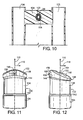
- FIG. 10 is a cross-sectional view of a guide member of the volatile material dispenser of FIG. 1 taken generally along the lines 10-10 of FIG. 6 , wherein structure behind the plane of section has been omitted for purposes of clarity;
- FIG. 11 is a front elevational view of a housing for the volatile material dispenser of FIG. 1 ;
- FIG. 12 is a right side elevational view of the housing of FIG. 11 ;
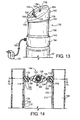
- FIG. 13 is a left and rear side isometric view of another embodiment of a housing for the volatile material dispenser of FIG. 1 similar to the ones shown in FIGS. 12 and 13 , except the present embodiment includes an AC connector and is mounted on a container;
- FIG. 14 is a cross-sectional view of a different embodiment showing an adjustable guide member taken along the lines 14-14 of FIG. 6 , wherein structure behind the plane of section has been omitted for purposes of clarity;
- FIG. 15 is a partial cross-sectional view of the adjustable guide member of FIG. 14 taken generally along the lines 15-15 of FIG. 14 ;
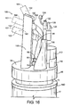
- FIG. 16 is a right side isometric view of another embodiment of a volatile material dispenser including the adjustable guide member depicted in FIGS. 14 and 15 ;
- FIG. 17 is a front elevational view of a housing for the volatile material dispenser of FIG. 16 including a slot and an aperture to accommodate a sensor;
- FIG. 18 is a right side elevational view of the housing of FIG. 17 further depicting a depressible panel.
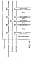
- FIG. 19 is a timing diagram illustrating the operation of the volatile material dispensers of FIGS. 1-18 according to a first operational sequence.
- FIGS. 1-7 depict a volatile material dispenser 50 adapted to be mounted on a container 52 (see FIGS. 1-5 and 7 ).
- the volatile material dispenser 50 discharges fluid from the container 52 upon the occurrence of a particular condition.
- the condition could be the manual activation of the volatile material dispenser 50 or the automatic activation of the volatile material dispenser 50 in response to an electrical signal from a timer or a sensor.
- the fluid discharged may be a fragrance or insecticide disposed within a carrier liquid, a deodorizing liquid, or the like.
- the fluid may also comprise other actives, such as sanitizers, air fresheners, odor eliminators, mold or mildew inhibitors, insect repellents, and/or the like, and/or that have aromatherapeutic properties.
- the fluid alternatively comprises any fluid known to those skilled in the art that may be dispensed from the container 52.
- the volatile material dispenser 50 is therefore adapted to dispense any number of different fluid formulations.
- the volatile material dispenser 50 includes a platform 54 that is disposed on a cylindrical section 56. As shown in FIG. 7 , the cylindrical section 56 is shaped to snap fit onto an upper end 58 of the container 52.
- FIG. 7 shows that the present embodiment includes an annular protrusion 60 projecting inwardly from an inner circumference 62 of the cylindrical section 56. A distal end 64 of the annular protrusion 60 forms a snap fit with an undercut 66 of the container 52 disposed between an upper mounting cup 68 and a lower mounting cup 70 on the upper end 58 of the container 52.
- the container 52 may be an aerosol container of any size and volume known to those skilled in the art.
- an aperture 72 is provided in the platform 54.
- the aperture 72 accommodates an inlet portion 74 of a discharge conduit 76, as shown in FIGS. 7-9 .
- the discharge conduit 76 includes a transverse medial portion 78 that connects the inlet portion 74 to an outlet portion 80.
- a continuous aperture 82 is disposed through the discharge conduit 76 from a base end 84 to an outlet end 86.
- a valve assembly (not shown) within the container 52 includes a tilt-activated valve stem 88 extending upwardly through a collar 90 disposed on an end surface 92 of the container 52.
- the base end 84 of the discharge conduit 76 is attached, e.g., by a press fit, over the tilt-activated valve stem 88.
- the continuous aperture 82 is in fluid communication with a bore 94 disposed through the tilt-activated valve stem 88.
- the discharge conduit 76 further includes a flange 96 that extends radially from the inlet portion 74 thereof.
- the tilt-activated valve stem 88 may be of the type described in Van der Heijden U.S. Patent No. 4,064,782 , which is herein incorporated by reference in its entirety.
- a flexible tube 98 includes an inlet end 100 that is attached to the outlet end 86 of the discharge conduit 76 as shown in FIGS. 1 , 3 , 4 , and 9 .
- the flexible tube 98 also includes a discharge end 101 as shown in FIGS. 1 , 2 , 4-6 , 15 , and 16 .
- a sleeve 102 is attached over the flexible tube 98 adjacent the discharge end 101 thereof as shown in FIGS. 2 , 6 , 10 , 14 , and 15 , e.g., by a press fit, an adhesive, a fastener, or by any other means of attachment.
- a guide member 104 such as shown in FIGS.
- the guide member 104 may be attached proximate to the discharge end 101 of the flexible tube 98 as shown in FIG. 10 , e.g., by a press fit therearound, by an adhesive, by a fastener, or by any means of attachment known to one having skill in the art. Further, it is contemplated in other embodiments that the guide member 104 may directly hold the flexible tube 98 by removing the sleeve 102. In this embodiment, the guide member 104 is attached between a pair of vertically extending battery holders 106 as shown in FIGS. 1-3 , 6 , and 10 .
- the flexible tube 98 has a continuous bore 108 therethrough as shown in FIGS. 2 , 6 , 9 , 10 , 14 , and 15 that provides fluid communication between the inlet end 100 and the discharge end 101 thereof.
- the tube may have an outer surface that is smooth or crenellated and that has a cross section that is circular, e.g., as depicted in FIG. 14 , or that is pentagonal, hexagonal, elliptical, triangular, square, octagonal, or any other shape known to one having ordinary skill in the art.
- the bore 108 through the tube 98 may have an inner surface that is smooth or crenellated and may have any desired cross section, e.g., circular, elliptical, square, triangular, pentagonal, hexagonal, octagonal, or any other shape that is the same or different than the cross section of the outer surface, as known to one having ordinary skill in the art.
- the cross sections of the outer surface of the tube 98 and the inner surface of the bore 108 may each be uniform or variable between the inlet end 100 and the discharge end 101 of the tube 98.
- a drive unit e.g., a solenoid assembly 112 driving a plunger 114, as shown in FIG. 8 , engages the flange 96 on the discharge conduit 76 when activated.
- a representative solenoid assembly for example, is a Ledex® Low Profile Battery Operated Linear Solenoid, size number 1ECM, model number 282342-025, which is available from Johnson Electric, Industry Products Group, Vandalia, Ohio.
- the 1ECM-282342-025 solenoid weighs 42.5 grams, is 25.4 mm in diameter and 13.5 mm tall.
- the 1ECM-282342-025 solenoid When operating on a 50% maximum duty cycle, the 1ECM-282342-025 solenoid nominally requires 2.9 volts DC, generates 2.2 Newtons (0.49 pounds) of force through a nominal stroke of 2 mm, and can remain energized for a maximum of 162 seconds.
- downward extension of the plunger 114 in a direction parallel with the longitudinal axis 110 causes downward displacement of the flange 96.
- the discharge conduit 76 is sufficiently rigid such that downward displacement of the flange 96 causes the base end 84 of the discharge conduit 76 to be displaced in a radial direction 116 away from the longitudinal axis 110, whereupon the tilt-activated valve stem 88 disposed within the base end 84 is also displaced in a radial direction 116 away from the longitudinal axis 110.
- a radial displacement includes any displacement of the distal end of the tilt-activated valve stem 88 away from the longitudinal axis 110. Such a radial displacement may therefore be characterized as a lateral or a transverse displacement of the distal end of the tilt-activated valve stem 88.
- the contents of the container 52 may be discharged in a continuous or metered dose. Further, the discharging of the contents of the container 52 may be effected in any number of ways, e.g., a discharge may comprise a partial metered dose or multiple consecutive discharges. It is also contemplated that any appropriate drive assembly having a capacity to downwardly displace the flange 96 as is known to one skilled in the art may be used to radially displace the tilt-activated valve stem 88. For example, it is contemplated that the drive assemblies shown in Application Nos. 11/801,554 and 11/893,456 , which are incorporated by reference herein in their entirety, may be adapted to work with the presently described embodiments.
- the solenoid assembly 112 is attached to the platform 54 by an attachment wall 118. In other embodiments, the solenoid assembly 112 may be attached to the platform 54 by support screws (not shown) extending from the solenoid assembly 112 or by other attachment mechanisms known to one having skill in the art.
- a pair of support pillars 120 extends upwardly from the platform 54.
- a printed circuit board 122 is held between the support pillars 120 and above the solenoid assembly 112.
- the printed circuit board 122 includes a light emitting diode (LED) 124 affixed to a front side thereof and extending upwardly therefrom.
- a linear switch assembly 126 is attached to a rear side of the printed circuit board 122.
- a positioning finger 128 extends from a rectangular slot 130 in the linear switch assembly 126.
- a housing 132 has a generally cylindrical shape and includes a lower portion 134, a medial portion 136 and an upper portion 138.
- the lower portion 134 includes an inwardly projecting annular lip (not shown) at a bottom end thereof.
- the annular lip is adapted to snap fit over a ridge 140 (see FIGS. 1-8 ) extending outwardly from an outer circumference of the container 52 to allow the housing 132 to be mounted on the container 52, such as shown in FIG. 13 .
- the medial portion 136 of the housing 132 has a slightly smaller diameter than the lower portion 134 and is connected thereto by a lower tapering shoulder 142.
- An upper tapering shoulder 144 connects the medial portion 136 to the upper portion 138, which has a diameter approximately equal to that of the lower portion 134.
- the housing 132 includes a back side 148 and a front side 150.
- the upper portion 138 includes a convex top surface 152 that generally slopes upwardly from the back side 148 to the front side 150.
- a circular aperture 154 is disposed through the top surface 152 to accommodate the LED 124 and a rectangular aperture 156 is disposed through the top surface 152 to accommodate the linear switch assembly 126.
- the front side 150 of the upper portion 138 includes an aperture 158 disposed therethrough for accommodation of the discharge end 101 of the flexible tube 98.
- the tilt-activated valve stem 88 in prior art devices is problematic due to an inherent lack of control of a specific direction of release of the fluid. As a result, fluid released through the tilt-activated valve stem 88 may tend to inappropriately spray into the housing 132, thereby undesirably coating the inner surfaces of the housing 132 instead of being directed to the environment. Inclusion of the flexible tube 98 prevents fluid released through the tilt-activated valve stem 88 from spraying into the inside of the housing 132.
- the flexible tube 98 allows the aperture 158 to be positioned on the housing 132 in a desired location to allow convenient and accurate directional spraying of the fluid from the volatile material dispenser 50. Further, the flexible tube 98 allows the aperture 158 to have a size or a shape without regard to directional spraying limitations of the tilt-activated valve stem 88.
- the housing 132 may be retained on the container 52 in any manner known by those skilled in the art.
- the retention structures described in Balfanz U.S. Patent No. 4,133,408 , Demarest U.S. Patent No. 5,027,982 , and Demarest et al. U.S. Patent No. 5,609,605 which are herein incorporated by reference in their entirety, may be used in connection with any of the embodiments described herein.
- the housing 132 may also be integral with and/or connectable to the volatile material dispenser 50, for example via a connection at the cylindrical section 56 thereof.
- the housing 132 may include an annular lip (not shown) projecting inwardly from an inner circumferential surface thereof.
- the annular lip may be adapted to snap over a bottom edge of the cylindrical section 56 or a corresponding outwardly protruding lip (not shown) on an outer circumferential surface of the cylindrical section 56.
- the housing may thus be retained directly on the volatile material dispenser 50 in addition to, or instead of, being retained on the container 52.
- any of the aesthetic aspects of the housing 132 described herein may be modified in any manner known by one skilled in the art, e.g., the medial portion 136 and the lower and upper tapering shoulders 142, 144 could be eliminated or the housing 132 could be provided with a different shape.
- Each of the vertically extending battery holders 106 is adapted to retain a battery, e.g., a size AA or AAA battery, therein to provide a D.C. power source to the drive unit.
- the batteries may be interchangeable with other power sources.
- the batteries may be replaced by a rechargeable Nickel-Cadmium battery or battery pack (not shown) having an electrical lead 160 that may be used to connect the battery pack to an A.C. power adapter 162 having an appropriate power transformer and A.C./D.C. converter as known to those of skill in the art (see FIG. 13 ).
- a volatile material dispenser 166 includes a pair of vertically extending battery holders 168, each including a groove 170 running vertically along inwardly facing edges 172 thereof.
- the adjustable guide member 164 includes a pair of end brackets 174.
- Each end bracket 174 has a support body 176 and a tongue 178 extending from the support body 176 and sized to snugly fit within one of the grooves 170.
- Each end bracket 174 also includes a circular slot 180 in a side of the end bracket 174 opposite from the tongue 178.
- the adjustable guide member 164 also includes a central support member 182 that has a circular arm 184 projecting laterally from each side thereof along an axis of rotation 186. Each circular arm 184 is snugly disposed within one of the circular slots 180.
- the central support member 182 may be attached proximate to the discharge end 101 of the flexible tube 98, e.g., by a press fit therearound as shown in FIG. 14 , by an adhesive, by a fastener, or by any means of attachment known to one having skill in the art.
- the end brackets 174 may be slid up or down along the grooves 170 and the circular arms 184 may be rotatably adjusted within the circular slots 180.
- a user may select the orientation and/or the positioning of the discharge end 101 of the flexible tube 98 with respect to the container 52.
- the adjustable guide member 164 allows the discharge end 101 of the flexible tube 98 to be fixedly held in a first position 188.
- the discharge end 101 of the flexible tube 98 may also be downwardly translated to be fixedly held in a second position 190 or may be upwardly translated and rotatably reoriented to be fixedly held in a third position 192.
- the adjustable guide member 164 allows a user to select any combined rotational orientation and vertical position of the discharge end 101 of the flexible tube 98 about the axis 186 and along the grooves 170, respectively.
- a volatile material dispenser similar to the embodiment shown in FIG. 16 includes a sensor (not shown) disposed on the platform 54 and facing radially away from the longitudinal axis 110. The sensor is in electronic communication with the printed circuit board 122 as will be further described in detail below.
- a housing 198 for the volatile material dispenser is shown in FIGS. 17 and 18 .
- the housing 198 is generally similar to the housing 132 described hereinabove with regard to FIGS. 11 and 12 except for the following differences.
- a discharge orifice or slot 200 is disposed through the upper portion 138 and the medial portion 136 along the front side 150 of the housing 198.
- the housing 198 also includes an aperture 202 disposed through the front side 150 of the lower portion 134.
- the housing 198 When the housing 198 is mounted on the container 52 over the volatile material dispenser a sensor is disposed in the aperture 202 to allow sensing of the environment. Further, the discharge end 101 of the flexible tube 98 may be adjusted by the adjustable guide member 164 to be disposed anywhere within the slot 200.
- a volatile material dispenser similar to the embodiment shown in FIG. 16 includes a normally open switch (not shown) having a manual pushbutton or other mechanical actuator known to one having skill in the art mounted on a base.
- the normally open switch may be electronically connected to the printed circuit board 122 to trigger activation of the drive unit.
- the manual pushbutton may be mechanically linked to the discharge conduit 76 by a mechanical linkage known to one skilled in the art such that depression of the manual pushbutton radially displaces the tilt-activated valve stem 88.
- the depressible panel 214 may be a living hinge or may be inwardly depressible in another way as known to one skilled in the art.
- the depressible panel 214 may also include a finger depression 216 to facilitate ease of use.
- FIG. 19 depicts a timing diagram that illustrates the operation of any of the volatile material dispensers hereinabove described during an in use condition.
- the volatile material dispenser for example the volatile material dispenser 166
- the volatile material dispenser 166 is energized by moving the positioning finger 128 of the linear switch assembly 126 from an "OFF" position 218 to one of four operating modes 220, 222, 224, and 226, as shown in FIG. 3 , whereupon a control circuit (not shown), which may be etched on the printed circuit board 122, causes the volatile material dispenser 166 to enter a startup delay period.
- Each of the four operating modes 220, 222, 224, and 226 corresponds to a predetermined sleep period between consecutive spraying periods.
- the first operating mode 220 may correspond to a five minute sleep period
- the second operating mode 222 may correspond to a seven and a half minute sleep period
- the third operating mode 224 may correspond to a fifteen minute sleep period
- the fourth operating mode 226 may correspond to a thirty minute sleep period.
- the solenoid assembly 112 Upon completion of the startup delay period, the solenoid assembly 112 is activated to discharge fluid from the container 52 during a first spraying period.
- the startup delay period is preferably about three seconds long, and the spraying period is typically about 98 milliseconds long.
- the volatile material dispenser 166 enters a first sleep period that lasts 5 minutes.
- the solenoid assembly 112 Upon expiration of the first sleep period the solenoid assembly 112 is activated to discharge fluid during a second spraying period. Thereafter, the volatile material dispenser 166 enters a second sleep period that lasts for 5 minutes. In the present example, the second sleep period is interrupted by the manual activation of the volatile material dispenser 166, whereupon fluid is dispensed during a third spraying period. Automatic operation thereafter continues with alternating sleep and spraying periods. At any time during a sleep period, the user may manually activate the volatile material dispenser 166 for a selectable or fixed period of time by depressing a manual pushbutton that may be mounted thereto as described above. Upon termination of the manual spraying operation, the volatile material dispenser 166 completes the pending sleep period. Thereafter, a spraying operation is undertaken.
- the linear switch assembly 126 may have a continuous range of settings instead of the four distinct operating modes 220, 222, 224, and 226 described above.
- the linear switch assembly 126 may be provided with a switch mechanism such as a dial (not shown), that provides for continuous user variation of the spraying period and/or the sleep period between continuous spray and sleep periods lasting several hours or days.
- the linear switch assembly 126 may be replaced and/or supplemented by a sensor, e.g., a photocell light sensor, which may be used as a motion detector. Alternatively, more than one sensor may be provided in lieu of the linear switch assembly 126 or in combination with same.
- the linear switch assembly 126 and a sensor are both provided in a volatile material dispenser.
- a user may choose to use the timer-based linear switch assembly 126 to automatically operate the solenoid assembly 112, or the user may choose to use the sensor to detect a given event prior to activating the solenoid assembly 112.
- a volatile material dispenser may operate in a timer and sensor based mode of operation concurrently.
- the senor may be a photocell light sensor.
- the photocell light sensor collects ambient light and allows the control circuit to detect any changes in the intensity thereof. Filtering of the photocell output is undertaken by the control circuit. If the control circuit determines that a threshold light condition has been reached, e.g., a predetermined level of change in light intensity, the control circuit develops a signal to activate the solenoid assembly 112. For example, if a volatile material dispenser including the photocell light sensor is placed in a lit bathroom, a person walking past the sensor may block a sufficient amount of ambient light from reaching the sensor to cause the control circuit to activate the solenoid assembly 112 and discharge a fluid.
- motion detectors known to those of skill in the art may also be utilized, e.g., a passive infrared or pyro-electric motion sensor, an infrared reflective motion sensor, an ultrasonic motion sensor, or a radar or microwave radio motion sensor.
- the LED 124 is illuminated when the volatile material dispenser 166 is in an operative state.
- the LED 124 blinks intermittently once every fifteen seconds during the sleep period.
- the blinking frequency of the LED 124 begins to increase as a spraying period becomes imminent.
- the more frequent illumination of the LED 124 serves as a visual indication that the volatile material dispenser 166 is about to discharge fluid contents into the atmosphere.
- any of the embodiments described herein may be modified to include any of the structures or methodologies disclosed in connection with different embodiments. Further, the present disclosure is not limited to aerosol containers of the type specifically shown. Still further, the volatile material dispensers of any of the embodiments disclosed herein may be modified to work with any type of fluid container having a tilt-activated valve stem.
- Aerosol dispensers are commonly used to dispense volatile materials such as air fresheners, deodorants, insecticides, germicides, decongestants, perfumes, and the like, that are stored within aerosol containers.
- Automated valve activation systems for aerosol containers allow the contents thereof to be released without human interaction, for example, according to a predetermined time schedule.
- Tilt-activated valve stems for aerosol container release valves typically require less force to operate than vertically activated valve stems, but may lack precise directional control.
- a system for automatically activating a tilt-activated valve stem providing selective directional control is presented. The system may be installed in a typical overcap for use with ordinary tilt-activated aerosol containers, resulting in an improvement in utility of the aerosol container.
Abstract
Description
- Not applicable
- Not applicable
- Not applicable
- The present disclosure relates generally to a valve activation system for the release of a volatile material from a container, and more particularly to a valve activation system having a flexible tube adapted to dispense an aerosolized fluid from a container having a tilt-activated valve stem.
- Aerosol containers are commonly used to store and dispense volatile materials such as air fresheners, deodorants, insecticides, germicides, decongestants, perfumes, and the like. The volatile material is stored under compression and typically in a liquid state within a container. A release valve on the container controls release of the volatile material contained under compression therein. The release valve typically has a valve stem that extends outwardly from the valve, wherein the valve is activated by the valve stem and the volatile material flows out of the container through the valve stem. In such a release valve, the valve is activated by a displacement of the valve stem with respect to a valve body. The valve stem may be displaced along a longitudinal axis of the valve stem, i.e., axially, or the valve stem may be tilted or displaced in a direction transverse to the longitudinal axis of the valve stem, i.e., radially.
- Activation of a release valve may be accomplished by an automated system or manually, In manual activation, a user may adjust an activation force applied to the valve as required to achieve a desired release. Therefore, consideration of applied force requirements is generally less important to design of manually activated release valves. Conventional actuator mechanisms may include motor driven linkages that apply downward pressure to depress the nozzle and open the valve within the container. Typically, these actuator mechanisms are unwieldy and are not readily adaptable to be used in a stand-alone manner and a hand-held manner. Further, many of these actuator mechanisms exhibit a great deal of power consumption. Generally, valves having tilt-activated valve stems require less force for activation than valves having vertically activated valve stems. Release valves requiring smaller activation forces are advantageous because such valves require less power to activate. Decreased power consumption will allow for longer power source life times. Smaller activation forces are also advantageous for automated activation because smaller required forces allow for simpler, smaller, and/or less costly automated designs.
- Existing automated valve activation systems for valves having tilt-activated valve stems are complex and may be difficult and expensive to manufacture. Complex systems including gears, springs, and precise interactions of a multitude of moving parts may also require more power to operate, have a greater tendency to break, and may be too large to fit within an overcap for placement on a volatile material container.
- Another disadvantage of current valve activation systems for valves having tilt-activated valve stems is the limited ability to control the direction in which the volatile material is released. In an axially activated valve, the volatile material is released along the longitudinal axis of the valve stem no matter how far the valve stem is depressed axially. However, in a tilt-activated valve stem, the direction of release depends on how far the tilt-activated valve stem has been displaced radially and/or the circumferential direction of the radial displacement. This limited ability to control the direction of release limits the type of overcap that may be used with a tilt-activated valve stem. To prevent a portion of the released volatile material from being captured within an overcap, the overcap must include an aperture large enough to accommodate a full range of release directions.
- According to one aspect of the invention, a volatile material dispenser comprises a drive unit adapted to be releasably mounted on a container having a tilt-activated valve stem. The drive unit is adapted to radially displace the tilt-activated valve stem. A flexible tube having a discharge end is fixedly held with respect to the container. The flexible tube is adapted to be in fluid communication with the tilt-activated valve stem.
- According to another aspect of the invention, a dispensing system comprises a housing adapted to be releasably mounted on a container having a tilt-activated valve stem, wherein the housing includes a discharge orifice. A flexible tube is adapted to be in fluid communication with the tilt-activated valve stem and has a discharge end fixedly disposed proximate to the discharge orifice. A drive unit is disposed within the housing, wherein the drive unit includes a solenoid assembly adapted to radially displace the tilt-activated valve stem.
- According to yet another aspect of the invention, a volatile material dispenser comprises a drive unit adapted to be mounted on a container. The drive unit is activated in response to a signal from at least a sensor to radially displace a tilt-activated valve stem of the container. A flexible tube has a discharge end fixedly held with respect to the container, wherein the flexible tube is adapted to be in fluid communication with the tilt-activated valve stem.
-
FIG. 1 is an isometric view of one embodiment of a volatile material dispenser mounted on a fluid container; -
FIG. 2 is a front elevational view of the volatile material dispenser ofFIG. 1 ; -
FIG. 3 is a rear elevational view of the volatile material dispenser ofFIG. 1 ; -
FIG. 4 is a right side elevational view of the volatile material dispenser ofFIG. 1 ; -
FIG. 5 is a left side elevational view of the volatile material dispenser ofFIG. 1 ; -
FIG. 6 is a top plan view of the volatile material dispenser ofFIG. 1 ; -
FIG. 7 is an right side elevational view partly in section taken along the lines 7-7 ofFIG. 6 with structure above a platform of the volatile material dispenser omitted for purposes of clarity; -
FIG. 8 is right side elevational view of the volatile material dispenser ofFIG. 1 with mounting brackets and support components omitted for purposes of clarity; -
FIG. 9 is a partial cross-sectional view of the volatile material dispenser taken generally along lines 9-9 ofFIG. 7 , wherein only the fluid container, a discharge conduit, and a flexible tube are shown for purposes of clarity; -
FIG. 10 is a cross-sectional view of a guide member of the volatile material dispenser ofFIG. 1 taken generally along the lines 10-10 ofFIG. 6 , wherein structure behind the plane of section has been omitted for purposes of clarity; -
FIG. 11 is a front elevational view of a housing for the volatile material dispenser ofFIG. 1 ; -
FIG. 12 is a right side elevational view of the housing ofFIG. 11 ; -
FIG. 13 is a left and rear side isometric view of another embodiment of a housing for the volatile material dispenser ofFIG. 1 similar to the ones shown inFIGS. 12 and13 , except the present embodiment includes an AC connector and is mounted on a container; -
FIG. 14 is a cross-sectional view of a different embodiment showing an adjustable guide member taken along the lines 14-14 ofFIG. 6 , wherein structure behind the plane of section has been omitted for purposes of clarity; -
FIG. 15 is a partial cross-sectional view of the adjustable guide member ofFIG. 14 taken generally along the lines 15-15 ofFIG. 14 ; -
FIG. 16 is a right side isometric view of another embodiment of a volatile material dispenser including the adjustable guide member depicted inFIGS. 14 and15 ; -
FIG. 17 is a front elevational view of a housing for the volatile material dispenser ofFIG. 16 including a slot and an aperture to accommodate a sensor; -
FIG. 18 is a right side elevational view of the housing ofFIG. 17 further depicting a depressible panel; and -
FIG. 19 is a timing diagram illustrating the operation of the volatile material dispensers ofFIGS. 1-18 according to a first operational sequence. - Other aspects and advantages of the present invention will become apparent upon consideration of the following detailed description, wherein similar structures have similar reference numerals.
-
FIGS. 1-7 depict avolatile material dispenser 50 adapted to be mounted on a container 52 (seeFIGS. 1-5 and7 ). Thevolatile material dispenser 50 discharges fluid from thecontainer 52 upon the occurrence of a particular condition. The condition could be the manual activation of thevolatile material dispenser 50 or the automatic activation of thevolatile material dispenser 50 in response to an electrical signal from a timer or a sensor. The fluid discharged may be a fragrance or insecticide disposed within a carrier liquid, a deodorizing liquid, or the like. The fluid may also comprise other actives, such as sanitizers, air fresheners, odor eliminators, mold or mildew inhibitors, insect repellents, and/or the like, and/or that have aromatherapeutic properties. The fluid alternatively comprises any fluid known to those skilled in the art that may be dispensed from thecontainer 52. Thevolatile material dispenser 50 is therefore adapted to dispense any number of different fluid formulations. - The
volatile material dispenser 50 includes aplatform 54 that is disposed on acylindrical section 56. As shown inFIG. 7 , thecylindrical section 56 is shaped to snap fit onto anupper end 58 of thecontainer 52.FIG. 7 shows that the present embodiment includes anannular protrusion 60 projecting inwardly from aninner circumference 62 of thecylindrical section 56. Adistal end 64 of theannular protrusion 60 forms a snap fit with an undercut 66 of thecontainer 52 disposed between an upper mountingcup 68 and alower mounting cup 70 on theupper end 58 of thecontainer 52. Thecontainer 52 may be an aerosol container of any size and volume known to those skilled in the art. - Referring to
FIG. 7 , an aperture 72 is provided in theplatform 54. The aperture 72 accommodates aninlet portion 74 of adischarge conduit 76, as shown inFIGS. 7-9 . As best seen inFIG. 9 , thedischarge conduit 76 includes a transversemedial portion 78 that connects theinlet portion 74 to anoutlet portion 80. Acontinuous aperture 82 is disposed through thedischarge conduit 76 from abase end 84 to anoutlet end 86. A valve assembly (not shown) within thecontainer 52 includes a tilt-activatedvalve stem 88 extending upwardly through acollar 90 disposed on anend surface 92 of thecontainer 52. Thebase end 84 of thedischarge conduit 76 is attached, e.g., by a press fit, over the tilt-activatedvalve stem 88. Thecontinuous aperture 82 is in fluid communication with abore 94 disposed through the tilt-activatedvalve stem 88. As seen inFIGS. 7 and8 , thedischarge conduit 76 further includes aflange 96 that extends radially from theinlet portion 74 thereof. The tilt-activatedvalve stem 88 may be of the type described inVan der Heijden U.S. Patent No. 4,064,782 , which is herein incorporated by reference in its entirety. - A
flexible tube 98 includes aninlet end 100 that is attached to the outlet end 86 of thedischarge conduit 76 as shown inFIGS. 1 ,3 ,4 , and9 . Theflexible tube 98 also includes adischarge end 101 as shown inFIGS. 1 ,2 ,4-6 ,15 , and16 . In the present embodiment, asleeve 102 is attached over theflexible tube 98 adjacent thedischarge end 101 thereof as shown inFIGS. 2 ,6 ,10 ,14 , and15 , e.g., by a press fit, an adhesive, a fastener, or by any other means of attachment. Aguide member 104, such as shown inFIGS. 2, 3 ,6 , and10 , fixedly holds thesleeve 102 to immobilize thedischarge end 101 of theflexible tube 98 with respect to thecontainer 52. Theguide member 104 may be attached proximate to thedischarge end 101 of theflexible tube 98 as shown inFIG. 10 , e.g., by a press fit therearound, by an adhesive, by a fastener, or by any means of attachment known to one having skill in the art. Further, it is contemplated in other embodiments that theguide member 104 may directly hold theflexible tube 98 by removing thesleeve 102. In this embodiment, theguide member 104 is attached between a pair of vertically extendingbattery holders 106 as shown inFIGS. 1-3 ,6 , and10 . - The
flexible tube 98 has acontinuous bore 108 therethrough as shown inFIGS. 2 ,6 ,9 ,10 ,14 , and15 that provides fluid communication between theinlet end 100 and thedischarge end 101 thereof. The tube may have an outer surface that is smooth or crenellated and that has a cross section that is circular, e.g., as depicted inFIG. 14 , or that is pentagonal, hexagonal, elliptical, triangular, square, octagonal, or any other shape known to one having ordinary skill in the art. Likewise, thebore 108 through thetube 98 may have an inner surface that is smooth or crenellated and may have any desired cross section, e.g., circular, elliptical, square, triangular, pentagonal, hexagonal, octagonal, or any other shape that is the same or different than the cross section of the outer surface, as known to one having ordinary skill in the art. Further, the cross sections of the outer surface of thetube 98 and the inner surface of thebore 108 may each be uniform or variable between theinlet end 100 and thedischarge end 101 of thetube 98. - In a non-active state, the tilt-activated
valve stem 88 is coincident with alongitudinal axis 110 of thecontainer 52 as shown inFIG. 7 . A drive unit, e.g., asolenoid assembly 112 driving aplunger 114, as shown inFIG. 8 , engages theflange 96 on thedischarge conduit 76 when activated. A representative solenoid assembly, for example, is a Ledex® Low Profile Battery Operated Linear Solenoid, size number 1ECM, model number 282342-025, which is available from Johnson Electric, Industry Products Group, Vandalia, Ohio. The 1ECM-282342-025 solenoid weighs 42.5 grams, is 25.4 mm in diameter and 13.5 mm tall. When operating on a 50% maximum duty cycle, the 1ECM-282342-025 solenoid nominally requires 2.9 volts DC, generates 2.2 Newtons (0.49 pounds) of force through a nominal stroke of 2 mm, and can remain energized for a maximum of 162 seconds. - As shown in
FIG. 8 , downward extension of theplunger 114 in a direction parallel with thelongitudinal axis 110 causes downward displacement of theflange 96. Thedischarge conduit 76 is sufficiently rigid such that downward displacement of theflange 96 causes thebase end 84 of thedischarge conduit 76 to be displaced in aradial direction 116 away from thelongitudinal axis 110, whereupon the tilt-activatedvalve stem 88 disposed within thebase end 84 is also displaced in aradial direction 116 away from thelongitudinal axis 110. When a distal end of the tilt-activatedvalve stem 88 is displaced radially to a sufficient degree, i.e., into an operable position, the valve assembly within thecontainer 52 is opened and the contents of thecontainer 52 are discharged through thebore 94 of the tilt-activatedvalve stem 88. In the terminology of the axisymmetric coordinate system used herein, a radial displacement includes any displacement of the distal end of the tilt-activatedvalve stem 88 away from thelongitudinal axis 110. Such a radial displacement may therefore be characterized as a lateral or a transverse displacement of the distal end of the tilt-activatedvalve stem 88. Release of fluid via thevolatile material dispenser 50 through the tilt-activatedvalve stem 88 may be problematic in prior art devices due to the lack of control of a specific direction of release, as mentioned hereinabove. However, the inclusion of theflexible tube 98 attached to thedischarge conduit 76 allows the fluid to be specifically directed in the present embodiment because thedischarge end 101 of theflexible tube 98 is fixedly held with respect to thecontainer 52 by theguide member 104. - The contents of the
container 52 may be discharged in a continuous or metered dose. Further, the discharging of the contents of thecontainer 52 may be effected in any number of ways, e.g., a discharge may comprise a partial metered dose or multiple consecutive discharges. It is also contemplated that any appropriate drive assembly having a capacity to downwardly displace theflange 96 as is known to one skilled in the art may be used to radially displace the tilt-activatedvalve stem 88. For example, it is contemplated that the drive assemblies shown in Application Nos.11/801,554 11/893,456 - Referring now to
FIGS. 1-6 , thesolenoid assembly 112 is attached to theplatform 54 by anattachment wall 118. In other embodiments, thesolenoid assembly 112 may be attached to theplatform 54 by support screws (not shown) extending from thesolenoid assembly 112 or by other attachment mechanisms known to one having skill in the art. A pair ofsupport pillars 120 extends upwardly from theplatform 54. A printedcircuit board 122 is held between thesupport pillars 120 and above thesolenoid assembly 112. The printedcircuit board 122 includes a light emitting diode (LED) 124 affixed to a front side thereof and extending upwardly therefrom. Alinear switch assembly 126 is attached to a rear side of the printedcircuit board 122. Apositioning finger 128 extends from arectangular slot 130 in thelinear switch assembly 126. - As shown in
FIGS. 11-13 , ahousing 132 has a generally cylindrical shape and includes alower portion 134, amedial portion 136 and anupper portion 138. Thelower portion 134 includes an inwardly projecting annular lip (not shown) at a bottom end thereof. The annular lip is adapted to snap fit over a ridge 140 (seeFIGS. 1-8 ) extending outwardly from an outer circumference of thecontainer 52 to allow thehousing 132 to be mounted on thecontainer 52, such as shown inFIG. 13 . Themedial portion 136 of thehousing 132 has a slightly smaller diameter than thelower portion 134 and is connected thereto by alower tapering shoulder 142. Anupper tapering shoulder 144 connects themedial portion 136 to theupper portion 138, which has a diameter approximately equal to that of thelower portion 134. - The
housing 132 includes aback side 148 and afront side 150. Theupper portion 138 includes a convextop surface 152 that generally slopes upwardly from theback side 148 to thefront side 150. Acircular aperture 154 is disposed through thetop surface 152 to accommodate theLED 124 and arectangular aperture 156 is disposed through thetop surface 152 to accommodate thelinear switch assembly 126. Thefront side 150 of theupper portion 138 includes anaperture 158 disposed therethrough for accommodation of thedischarge end 101 of theflexible tube 98. - As discussed hereinabove, use of the tilt-activated
valve stem 88 in prior art devices is problematic due to an inherent lack of control of a specific direction of release of the fluid. As a result, fluid released through the tilt-activatedvalve stem 88 may tend to inappropriately spray into thehousing 132, thereby undesirably coating the inner surfaces of thehousing 132 instead of being directed to the environment. Inclusion of theflexible tube 98 prevents fluid released through the tilt-activated valve stem 88 from spraying into the inside of thehousing 132. Theflexible tube 98 allows theaperture 158 to be positioned on thehousing 132 in a desired location to allow convenient and accurate directional spraying of the fluid from thevolatile material dispenser 50. Further, theflexible tube 98 allows theaperture 158 to have a size or a shape without regard to directional spraying limitations of the tilt-activatedvalve stem 88. - The
housing 132 may be retained on thecontainer 52 in any manner known by those skilled in the art. For example, the retention structures described inBalfanz U.S. Patent No. 4,133,408 ,Demarest U.S. Patent No. 5,027,982 , andDemarest et al. U.S. Patent No. 5,609,605 , which are herein incorporated by reference in their entirety, may be used in connection with any of the embodiments described herein. Thehousing 132 may also be integral with and/or connectable to thevolatile material dispenser 50, for example via a connection at thecylindrical section 56 thereof. Illustratively, thehousing 132 may include an annular lip (not shown) projecting inwardly from an inner circumferential surface thereof. The annular lip may be adapted to snap over a bottom edge of thecylindrical section 56 or a corresponding outwardly protruding lip (not shown) on an outer circumferential surface of thecylindrical section 56. The housing may thus be retained directly on thevolatile material dispenser 50 in addition to, or instead of, being retained on thecontainer 52. Further, any of the aesthetic aspects of thehousing 132 described herein may be modified in any manner known by one skilled in the art, e.g., themedial portion 136 and the lower and upper tapering shoulders 142, 144 could be eliminated or thehousing 132 could be provided with a different shape. - Each of the vertically extending
battery holders 106 is adapted to retain a battery, e.g., a size AA or AAA battery, therein to provide a D.C. power source to the drive unit. In some embodiments, the batteries may be interchangeable with other power sources. For example, the batteries may be replaced by a rechargeable Nickel-Cadmium battery or battery pack (not shown) having anelectrical lead 160 that may be used to connect the battery pack to anA.C. power adapter 162 having an appropriate power transformer and A.C./D.C. converter as known to those of skill in the art (seeFIG. 13 ). - In another embodiment, the
discharge end 101 of theflexible tube 98 is fixedly held with respect to thecontainer 52 by anadjustable guide member 164, e,g., such as the one shown inFIGS. 14 and15 . In this embodiment, a volatile material dispenser 166 (seeFIG. 16 ) includes a pair of vertically extendingbattery holders 168, each including agroove 170 running vertically along inwardly facingedges 172 thereof. Theadjustable guide member 164 includes a pair ofend brackets 174. Eachend bracket 174 has asupport body 176 and atongue 178 extending from thesupport body 176 and sized to snugly fit within one of thegrooves 170. Eachend bracket 174 also includes acircular slot 180 in a side of theend bracket 174 opposite from thetongue 178. Theadjustable guide member 164 also includes acentral support member 182 that has acircular arm 184 projecting laterally from each side thereof along an axis ofrotation 186. Eachcircular arm 184 is snugly disposed within one of thecircular slots 180. Thecentral support member 182 may be attached proximate to thedischarge end 101 of theflexible tube 98, e.g., by a press fit therearound as shown inFIG. 14 , by an adhesive, by a fastener, or by any means of attachment known to one having skill in the art. - The
end brackets 174 may be slid up or down along thegrooves 170 and thecircular arms 184 may be rotatably adjusted within thecircular slots 180. By such selective adjustment of theadjustable guide member 164, a user may select the orientation and/or the positioning of thedischarge end 101 of theflexible tube 98 with respect to thecontainer 52. As shown inFIG. 16 , theadjustable guide member 164 allows thedischarge end 101 of theflexible tube 98 to be fixedly held in afirst position 188. Thedischarge end 101 of theflexible tube 98 may also be downwardly translated to be fixedly held in asecond position 190 or may be upwardly translated and rotatably reoriented to be fixedly held in athird position 192. Indeed, theadjustable guide member 164 allows a user to select any combined rotational orientation and vertical position of thedischarge end 101 of theflexible tube 98 about theaxis 186 and along thegrooves 170, respectively. - In a further embodiment, a volatile material dispenser similar to the embodiment shown in
FIG. 16 includes a sensor (not shown) disposed on theplatform 54 and facing radially away from thelongitudinal axis 110. The sensor is in electronic communication with the printedcircuit board 122 as will be further described in detail below. Ahousing 198 for the volatile material dispenser is shown inFIGS. 17 and 18 . Thehousing 198 is generally similar to thehousing 132 described hereinabove with regard toFIGS. 11 and 12 except for the following differences. A discharge orifice orslot 200 is disposed through theupper portion 138 and themedial portion 136 along thefront side 150 of thehousing 198. Thehousing 198 also includes anaperture 202 disposed through thefront side 150 of thelower portion 134. When thehousing 198 is mounted on thecontainer 52 over the volatile material dispenser a sensor is disposed in theaperture 202 to allow sensing of the environment. Further, thedischarge end 101 of theflexible tube 98 may be adjusted by theadjustable guide member 164 to be disposed anywhere within theslot 200. - In yet another embodiment, a volatile material dispenser similar to the embodiment shown in
FIG. 16 includes a normally open switch (not shown) having a manual pushbutton or other mechanical actuator known to one having skill in the art mounted on a base. The normally open switch may be electronically connected to the printedcircuit board 122 to trigger activation of the drive unit. Alternatively, the manual pushbutton may be mechanically linked to thedischarge conduit 76 by a mechanical linkage known to one skilled in the art such that depression of the manual pushbutton radially displaces the tilt-activatedvalve stem 88. Adepressible panel 214 on theback side 148 of themedial portion 136 of thehousing 198, as shown inFIG. 18 , may be adapted to contact and depress the manual pushbutton when thehousing 198 is mounted to thecontainer 52. Thedepressible panel 214 may be a living hinge or may be inwardly depressible in another way as known to one skilled in the art. Thedepressible panel 214 may also include afinger depression 216 to facilitate ease of use. -
FIG. 19 depicts a timing diagram that illustrates the operation of any of the volatile material dispensers hereinabove described during an in use condition. Initially, the volatile material dispenser, for example thevolatile material dispenser 166, is energized by moving thepositioning finger 128 of thelinear switch assembly 126 from an "OFF"position 218 to one of four operatingmodes FIG. 3 , whereupon a control circuit (not shown), which may be etched on the printedcircuit board 122, causes thevolatile material dispenser 166 to enter a startup delay period. Each of the fouroperating modes first operating mode 220 may correspond to a five minute sleep period, thesecond operating mode 222 may correspond to a seven and a half minute sleep period, thethird operating mode 224 may correspond to a fifteen minute sleep period, and thefourth operating mode 226 may correspond to a thirty minute sleep period. For the present example, we shall assume thefirst operating mode 220 has been chosen. Upon completion of the startup delay period, thesolenoid assembly 112 is activated to discharge fluid from thecontainer 52 during a first spraying period. The startup delay period is preferably about three seconds long, and the spraying period is typically about 98 milliseconds long. Upon completion of the first spraying period, thevolatile material dispenser 166 enters a first sleep period that lasts 5 minutes. Upon expiration of the first sleep period thesolenoid assembly 112 is activated to discharge fluid during a second spraying period. Thereafter, thevolatile material dispenser 166 enters a second sleep period that lasts for 5 minutes. In the present example, the second sleep period is interrupted by the manual activation of thevolatile material dispenser 166, whereupon fluid is dispensed during a third spraying period. Automatic operation thereafter continues with alternating sleep and spraying periods. At any time during a sleep period, the user may manually activate thevolatile material dispenser 166 for a selectable or fixed period of time by depressing a manual pushbutton that may be mounted thereto as described above. Upon termination of the manual spraying operation, thevolatile material dispenser 166 completes the pending sleep period. Thereafter, a spraying operation is undertaken. - In another embodiment, the
linear switch assembly 126 may have a continuous range of settings instead of the fourdistinct operating modes linear switch assembly 126 may be provided with a switch mechanism such as a dial (not shown), that provides for continuous user variation of the spraying period and/or the sleep period between continuous spray and sleep periods lasting several hours or days. In a further embodiment, thelinear switch assembly 126 may be replaced and/or supplemented by a sensor, e.g., a photocell light sensor, which may be used as a motion detector. Alternatively, more than one sensor may be provided in lieu of thelinear switch assembly 126 or in combination with same. It is anticipated that one skilled in the art may provide any type of sensor either alone or in combination with thelinear switch assembly 126 and/or other sensors to meet the needs of a user. In one particular embodiment (not shown), e.g., thelinear switch assembly 126 and a sensor are both provided in a volatile material dispenser. In such an embodiment, a user may choose to use the timer-basedlinear switch assembly 126 to automatically operate thesolenoid assembly 112, or the user may choose to use the sensor to detect a given event prior to activating thesolenoid assembly 112. Alternatively, such a volatile material dispenser may operate in a timer and sensor based mode of operation concurrently. - As noted above, the sensor may be a photocell light sensor. The photocell light sensor collects ambient light and allows the control circuit to detect any changes in the intensity thereof. Filtering of the photocell output is undertaken by the control circuit. If the control circuit determines that a threshold light condition has been reached, e.g., a predetermined level of change in light intensity, the control circuit develops a signal to activate the
solenoid assembly 112. For example, if a volatile material dispenser including the photocell light sensor is placed in a lit bathroom, a person walking past the sensor may block a sufficient amount of ambient light from reaching the sensor to cause the control circuit to activate thesolenoid assembly 112 and discharge a fluid. Further, other motion detectors known to those of skill in the art may also be utilized, e.g., a passive infrared or pyro-electric motion sensor, an infrared reflective motion sensor, an ultrasonic motion sensor, or a radar or microwave radio motion sensor. - The
LED 124 is illuminated when thevolatile material dispenser 166 is in an operative state. TheLED 124 blinks intermittently once every fifteen seconds during the sleep period. Depending on the selected operating mode, the blinking frequency of theLED 124 begins to increase as a spraying period becomes imminent. The more frequent illumination of theLED 124 serves as a visual indication that thevolatile material dispenser 166 is about to discharge fluid contents into the atmosphere. - Any of the embodiments described herein may be modified to include any of the structures or methodologies disclosed in connection with different embodiments. Further, the present disclosure is not limited to aerosol containers of the type specifically shown. Still further, the volatile material dispensers of any of the embodiments disclosed herein may be modified to work with any type of fluid container having a tilt-activated valve stem.
- Aerosol dispensers are commonly used to dispense volatile materials such as air fresheners, deodorants, insecticides, germicides, decongestants, perfumes, and the like, that are stored within aerosol containers. Automated valve activation systems for aerosol containers allow the contents thereof to be released without human interaction, for example, according to a predetermined time schedule. Tilt-activated valve stems for aerosol container release valves typically require less force to operate than vertically activated valve stems, but may lack precise directional control. A system for automatically activating a tilt-activated valve stem providing selective directional control is presented. The system may be installed in a typical overcap for use with ordinary tilt-activated aerosol containers, resulting in an improvement in utility of the aerosol container.
- Numerous modifications to the present invention will be apparent to those skilled in the art in view of the foregoing description. Accordingly, this description is to be construed as illustrative only and is presented for the purpose of enabling those skilled in the art to make and use the invention and to teach the best mode of carrying out same. The exclusive rights to all modifications which come within the scope of the appended claims are reserved.
Further embodiments forming part of the present disclosure are set out in the paragraphs that follow. -
Paragraph 1. A volatile material dispenser, comprising: a drive unit adapted to be releasably mounted on a container having a tilt-activated valve stem, wherein the drive unit is adapted to radially displace the tilt-activated valve stem; and a flexible tube having a discharge end fixedly held with respect to the container, wherein the flexible tube is adapted to be in fluid communication with the tilt-activated valve stem. - Paragraph 2. The volatile material dispenser of
paragraph 1 further comprising a discharge conduit for disposition between an inlet end of the flexible tube and a tilt-activated valve stem to provide fluid communication between the tilt-activated valve stem and the inlet end of the flexible tube. - Paragraph 3. The volatile material dispenser of paragraph 2, wherein the discharge conduit comprises an inlet portion, an outlet portion disposed parallel to the inlet portion, and a transverse medial portion connecting the inlet portion and the outlet portion.
- Paragraph 4. The volatile material dispenser of paragraph 3, wherein the discharge conduit includes a flange extending radially therefrom.
- Paragraph 5. The volatile material dispenser of paragraph 4, wherein the drive unit includes a plunger adapted to engage and axially displace the flange of the discharge conduit to radially displace a tilt-activated valve stem.
- Paragraph 6. The volatile material dispenser of
paragraph 1, wherein the discharge end of the flexible tube is fixedly held with respect to a container by a guide member allowing adjustable orientation and positioning of the discharge end with respect to the container. - Paragraph 7. The volatile material dispenser of paragraph 6, wherein the discharge end of the flexible tube is oriented radially away from a longitudinal axis of a container.
- Paragraph 8. The volatile material dispenser of paragraph 6, wherein the discharge end of the flexible tube is held axially parallel to a longitudinal axis of a container.
-
Paragraph 9. The volatile material dispenser ofparagraph 1 further including a container having a tilt- activated valve stem. - Paragraph 10. A dispensing system, comprising: a housing adapted to be releasably mounted on a container having a tilt-activated valve stem, wherein the housing includes a discharge orifice; a flexible tube adapted to be in fluid communication with the tilt-activated valve stem and having a discharge end fixedly disposed proximate to the discharge orifice; and a drive unit disposed within the housing, wherein the drive unit includes a solenoid assembly adapted to radially displace the tilt-activated valve stem.
- Paragraph 11. The dispensing system of paragraph 10, wherein the discharge orifice of the housing can accommodate a plurality of fixedly disposed positions of the discharge end of the flexible tube.
- Paragraph 12. The dispensing system of paragraph 10 further including a container having a tilt-activated valve stem.
- Paragraph 13. A volatile material dispenser, comprising: a drive unit adapted to be mounted on a container, wherein the drive unit is adapted to be activated in response to a signal from at least a sensor to radially displace a tilt-activated valve stem of the container; and a flexible tube having a discharge end fixedly held with respect to the container, wherein the flexible tube is adapted to be in fluid communication with the tilt-activated valve stem.
- Paragraph 14. The volatile material dispenser of paragraph 13, wherein the drive unit is activated in response to a signal from a timer.
-
Paragraph 15. The volatile material dispenser of paragraph 14 further including a switch assembly that provides one or more operating modes for the timer. - Paragraph 16. The volatile material dispenser of claim 13, wherein the drive unit is activated in response to a signal from a manual actuator.
- Paragraph 17. The volatile material dispenser of paragraph 13, wherein the sensor is a photocell light sensor.
- Paragraph 18. The volatile material dispenser of paragraph 13, wherein the sensor is an ultrasonic motion sensor.
- Paragraph 19. The volatile material dispenser of paragraph 13, wherein the sensor is a microwave radio motion sensor.
- Paragraph 20. The volatile material dispenser of paragraph 13 further including a container having a tilt- activated valve stem.
Claims (15)
- A volatile material dispenser, comprising:a drive unit (42, 114) adapted to be mounted on a container (52), wherein the drive unit is adapted to be activated in response to a signal from at least a sensor to radially displace a tilt-activated valve stem (88) of the container (52); anda flexible tube (98) having a discharge end (101) fixedly held with respect to the container, wherein the flexible tube (98) is adapted to be in fluid communication with the tilt-activated valve stem (88).
- The volatile material dispenser of claim 1, wherein the drive unit (42,114) is activated in response to a signal from a timer.
- The volatile material dispenser of claim 2 further including a switch assembly that provides one or more operating modes for the timer.
- The volatile material dispenser of claim 1, wherein the drive unit (42, 114) is activated in response to a signal from a manual actuator.
- The volatile material dispenser of claim 1, wherein the sensor is a photocell light sensor.
- The volatile material dispenser of claim 1, wherein the sensor is an ultrasonic motion sensor.
- The volatile material dispenser of claim 1, wherein the sensor is a microwave radio motion sensor.
- The volatile material dispenser of claim 1 further including a container (52) having a tilt-activated valve stem (88).
- The volatile material dispenser of claim 1 further including a container having a tilt- activated valve stem.
- The volatile material dispenser of any preceding claim further including a discharge conduit for disposition between an inlet end of the flexible tube and a tilt-activated valve stem to provide fluid communication between the tilt-activated valve stem and the inlet end of the flexible tube; wherein
the discharge conduit comprises an inlet portion, an outlet portion disposed parallel to the inlet portion, and a transverse medial portion connecting the inlet portion and the outlet portion. - The volatile material dispenser of any of claims 1-9 wherein the discharge end of the flexible tube is fixedly held with respect to a container by a guide member allowing adjustable orientation and positioning of the discharge end with respect to the container.
- A dispensing system, comprising:a container (52) having a tilt activated valve (88); anda housing adapted to be releasably mounted on the container (52), the housing including a volatile material dispenser accodring to any preceding claim.
- A dispensing system, comprising:a housing adapted to be releasably mounted on a container (52) having a tilt-activated valve stem (88), wherein the housing includes a discharge orifice;a flexible tube (98) adapted to be in fluid communication with the tilt-activated valve stem (88) and having a discharge end (101) fixedly disposed proximate to the discharge orifice; anda drive unit (212,114) disposed within the housing, wherein the drive unit (112, 114) includes a solenoid assembly adapted to radially displace the tilt-activated valve stem (88).
- The dispensing system of claim 9, wherein the discharge orifice of the housing can accommodate a plurality of fixedly disposed positions of the discharge end of the flexible tube (98).
- The dispensing system of claim 9 further including a container (52) having a tilt-activated valve stem (88).
Applications Claiming Priority (2)
| Application Number | Priority Date | Filing Date | Title |
|---|---|---|---|
| US12/054,054 US8387827B2 (en) | 2008-03-24 | 2008-03-24 | Volatile material dispenser |
| EP09724279A EP2257318A2 (en) | 2008-03-24 | 2009-03-24 | Volatile material dispenser for aerosol can |
Related Parent Applications (2)
| Application Number | Title | Priority Date | Filing Date |
|---|---|---|---|
| EP09724279.6 Division | 2009-03-24 | ||
| EP09724279A Division EP2257318A2 (en) | 2008-03-24 | 2009-03-24 | Volatile material dispenser for aerosol can |
Publications (2)
| Publication Number | Publication Date |
|---|---|
| EP2529760A1 true EP2529760A1 (en) | 2012-12-05 |
| EP2529760B1 EP2529760B1 (en) | 2014-06-25 |
Family
ID=40671255
Family Applications (2)
| Application Number | Title | Priority Date | Filing Date |
|---|---|---|---|
| EP09724279A Withdrawn EP2257318A2 (en) | 2008-03-24 | 2009-03-24 | Volatile material dispenser for aerosol can |
| EP12178012.6A Active EP2529760B1 (en) | 2008-03-24 | 2009-03-24 | Volatile material dispenser |
Family Applications Before (1)
| Application Number | Title | Priority Date | Filing Date |
|---|---|---|---|
| EP09724279A Withdrawn EP2257318A2 (en) | 2008-03-24 | 2009-03-24 | Volatile material dispenser for aerosol can |
Country Status (10)
| Country | Link |
|---|---|
| US (2) | US8387827B2 (en) |
| EP (2) | EP2257318A2 (en) |
| JP (1) | JP2011517973A (en) |
| KR (1) | KR20100126759A (en) |
| CN (2) | CN102026674B (en) |
| AU (1) | AU2009229317B2 (en) |
| BR (1) | BRPI0909076A2 (en) |
| CA (1) | CA2719218C (en) |
| ES (1) | ES2487942T3 (en) |
| WO (1) | WO2009120318A2 (en) |
Families Citing this family (22)
| Publication number | Priority date | Publication date | Assignee | Title |
|---|---|---|---|---|
| US8826470B2 (en) | 2010-05-21 | 2014-09-09 | S.C. Johnson & Son, Inc. | Aerosol dispenser control system |
| US8255089B2 (en) * | 2010-05-28 | 2012-08-28 | S.C. Johnson & Son, Inc. | Multiple volatile material dispensing device and operating methodologies therefore |
| GB201202578D0 (en) | 2012-02-15 | 2012-03-28 | Reckitt Benckiser Llc | Dispenser and refill unit and dispensing methods |
| US8622259B2 (en) * | 2012-04-09 | 2014-01-07 | Hsu-Hui Chang | Electrical valve control device |
| US8894044B2 (en) * | 2012-08-17 | 2014-11-25 | S.C. Johnson & Son, Inc. | Dispenser |
| US9247724B2 (en) * | 2012-09-07 | 2016-02-02 | S.C. Johnson & Son, Inc. | Product dispensing system |
| ES2640713T3 (en) * | 2013-12-09 | 2017-11-06 | Unilever Nv | Spray dispensing head |
| USD743806S1 (en) * | 2013-12-20 | 2015-11-24 | S.C. Johnson & Son, Inc. | Combined Sprayer and Refill Bottles |
| US9808812B2 (en) * | 2014-06-20 | 2017-11-07 | The Procter & Gamble Company | Microfluidic delivery system |
| US9353881B2 (en) * | 2014-08-12 | 2016-05-31 | Hsu-Hui Chang | Isolated electrically-controlled valve |
| US9482496B1 (en) * | 2015-06-01 | 2016-11-01 | Fighting Chance Systems, Inc. | Wall-mounted nonlethal device for defending against intruders |
| US9550009B1 (en) * | 2015-09-17 | 2017-01-24 | Prolitec Inc. | Air treatment systems and methods |
| CN106489402A (en) * | 2016-10-13 | 2017-03-15 | 天津恺丰义科技有限公司 | A kind of hydraulic fertilizer device |
| EP3378569A1 (en) | 2017-03-21 | 2018-09-26 | The Procter & Gamble Company | Dispensing device |
| US10293353B2 (en) | 2017-04-25 | 2019-05-21 | Gpcp Ip Holdings Llc | Automated flowable material dispensers and related methods for dispensing flowable material |
| EP3489171A1 (en) | 2017-11-23 | 2019-05-29 | The Procter & Gamble Company | Piston with flexible closure for aerosol container |
| EP3513880B1 (en) | 2018-01-23 | 2021-08-25 | The Procter & Gamble Company | Dispensing device suitable for a foamable product |
| CA184784S (en) * | 2018-05-24 | 2019-12-30 | Zobele Holding Spa | Diffusing evaporator of active substances |
| US11027909B2 (en) | 2018-08-15 | 2021-06-08 | Gpcp Ip Holdings Llc | Automated flowable material dispensers and related methods for dispensing flowable material |
| US11267644B2 (en) | 2018-11-08 | 2022-03-08 | The Procter And Gamble Company | Aerosol foam dispenser and methods for delivering a textured foam product |
| US10850914B2 (en) * | 2018-11-08 | 2020-12-01 | The Procter And Gamble Company | Dip tube aerosol dispenser with upright actuator |
| DE102021116565A1 (en) | 2021-06-26 | 2022-12-29 | IC Medical GmbH | #Adapter for coupling a hollow body in the medical field with a reservoir for a treatment agent |
Citations (8)
| Publication number | Priority date | Publication date | Assignee | Title |
|---|---|---|---|---|
| US4064782A (en) | 1976-05-06 | 1977-12-27 | Daniel Laflamme | Electronic music display device |
| US4133408A (en) | 1977-10-27 | 1979-01-09 | General Motors Corporation | Flow amplifier valve assembly |
| US5027982A (en) | 1990-03-29 | 1991-07-02 | S. C. Johnson & Son, Inc. | Aerosol actuator and overcap assembly |
| US5609605A (en) | 1994-08-25 | 1997-03-11 | Ethicon, Inc. | Combination arterial stent |
| US20050224596A1 (en) * | 2003-07-08 | 2005-10-13 | Panopoulos Peter J | Machine that is an automatic pesticide, insecticide, repellant, poison, air freshener, disinfectant or other type of spray delivery system |
| WO2006074454A2 (en) * | 2005-01-10 | 2006-07-13 | Hyso Technology Llc | Door handle sanitizer system and valve attachment apparatus |
| WO2009023208A1 (en) * | 2007-08-16 | 2009-02-19 | S. C. Johnson & Son, Inc. | Tilt-activated valve stem actuator |
| WO2009025741A1 (en) * | 2007-08-16 | 2009-02-26 | S. C. Johnson & Son, Inc. | Overcap and system for spraying a fluid |
Family Cites Families (351)
| Publication number | Priority date | Publication date | Assignee | Title |
|---|---|---|---|---|
| US3155290A (en) * | 1964-11-03 | Aerosol valve | ||
| US3127060A (en) | 1964-03-31 | Automatic actuator for spray containers | ||
| US3273610A (en) | 1966-09-20 | Valved pressurized fluid dispensing receptacle with receptacle-attached fitting | ||
| US2506449A (en) * | 1946-11-18 | 1950-05-02 | Airosol Company Inc | Pressure valve |
| US2608319A (en) | 1948-01-15 | 1952-08-26 | Stanton H Petry | Gas discharge device for gas bombs |
| US2613108A (en) | 1949-04-01 | 1952-10-07 | George F Kraus | Fluid dispenser |
| US2662669A (en) * | 1950-01-09 | 1953-12-15 | Crown Can Company | Dispensing container and slitted resilient valve therefor |
| US2763406A (en) * | 1952-06-05 | 1956-09-18 | James H Countryman | Valve construction for dispensing containers |
| US3088682A (en) * | 1954-06-22 | 1963-05-07 | Risdon Mfg Co | Combined actuator button and spray nozzle devices for aerosol valves |
| BE543634A (en) * | 1956-09-20 | |||
| US2948439A (en) * | 1956-11-16 | 1960-08-09 | Wheaton Glass Company | Reinforced glass aerosol containers and method of making same |
| US2868419A (en) * | 1956-12-04 | 1959-01-13 | Jr William D Casey | Pressurized container closure |
| US2928573A (en) | 1958-02-25 | 1960-03-15 | Syncro Mist Controls Inc | Valve actuating assembly for metered spray atomizing devices |
| US3028054A (en) * | 1958-06-18 | 1962-04-03 | Risdon Mfg Co | Remote actuating means for aerosol dispensers |
| US3050281A (en) * | 1959-08-31 | 1962-08-21 | Gilbert G Budwig | Dispensing valve |
| US3018929A (en) * | 1959-09-03 | 1962-01-30 | Vastano Joseph J | Aerosol valve |
| US3023427A (en) * | 1960-04-18 | 1962-03-06 | Daniel T Behringer | Device for sterilizing and deodorizing toilet bowls |
| US3018056A (en) * | 1960-09-29 | 1962-01-23 | Montgomery Mfg Company Inc | Timed spray dispensers |
| US3161196A (en) * | 1961-03-21 | 1964-12-15 | Menlo Park Lab Inc | Hygienic dispenser apparatus |
| GB1033025A (en) | 1962-02-19 | 1966-06-15 | Heuer Timer Corp | Intermittent valve-actuating device for portable pressurised aerosol dispensers |
| US3165238A (en) * | 1962-02-19 | 1965-01-12 | Heuer Timer Corp | Intermittent actuating device for dispensers |
| US3185356A (en) | 1962-03-27 | 1965-05-25 | Risdon Mfg Co | Metering valve |
| US3154224A (en) * | 1962-11-15 | 1964-10-27 | Risdon Mfg Co | Valve actuator for pressurized package |
| US3115277A (en) | 1963-01-22 | 1963-12-24 | Jr Charles A Montague | Pressure can device |
| US3178070A (en) * | 1963-02-15 | 1965-04-13 | Ragnvald G Leland | Toilet bowl deodorizer |
| US3199732A (en) | 1963-03-20 | 1965-08-10 | Robertshaw Controls Co | Spray timer |
| US3289886A (en) | 1964-02-24 | 1966-12-06 | Goldsholl Morton | Timing device and method |
| US3228609A (en) | 1964-05-26 | 1966-01-11 | Syncro Mist Controls Inc | Spray dispenser |
| US3180532A (en) | 1964-06-18 | 1965-04-27 | Clayton Corp Of Delaware | Tamper-proof cover for a container |
| US3269602A (en) | 1964-09-24 | 1966-08-30 | Time Mist Inc | Periodically operated aerosol dispenser |
| US3240389A (en) | 1964-12-24 | 1966-03-15 | Robertshaw Controls Co | Spray timer |
| US3270925A (en) * | 1964-12-28 | 1966-09-06 | Vastano Joseph J | Aerosol valve and method of manufacture of same |
| US3329314A (en) | 1965-08-20 | 1967-07-04 | Gen Time Corp | Timed actuating device for aerosol dispenser |
| US3305134A (en) | 1965-10-21 | 1967-02-21 | Union Carbide Corp | Automatic spray device |
| US3368717A (en) | 1965-10-24 | 1968-02-13 | Time Mist Inc | Dispenser |
| US3326418A (en) | 1966-01-21 | 1967-06-20 | Willis A Kropp | Dispensing device |
| US3398864A (en) | 1966-06-24 | 1968-08-27 | Gen Time Corp | Adapter apparatus for automatic aerosol dispenser |
| US3455485A (en) | 1967-03-20 | 1969-07-15 | Lawrence T Crownover | Automatic cycling mechanism |
| US3419189A (en) | 1967-08-21 | 1968-12-31 | Iketani Taisho | Device for automatically and intermittently spraying pressurized products |
| US3411670A (en) | 1967-09-11 | 1968-11-19 | Edward L Brown | Automatic dispenser for pressurized liquid |
| US3497108A (en) | 1967-10-26 | 1970-02-24 | Dart Ind Inc | Automatic dispenser |
| US3543122A (en) | 1968-01-02 | 1970-11-24 | Air Guard Control Canada Ltd | Automatic aerosol dispenser |
| US3515316A (en) * | 1968-02-21 | 1970-06-02 | Scovill Manufacturing Co | Actuator for aerosol valves |
| US3477613A (en) | 1968-02-29 | 1969-11-11 | Dart Ind Inc | Aerosol dispenser actuated by propellant pressure |
| US3497110A (en) | 1968-04-12 | 1970-02-24 | Eversharp Inc | Aerosol dispenser |
| US3591058A (en) | 1968-11-05 | 1971-07-06 | Republic Corp | Tapping device for beer kegs and the like |
| US3540624A (en) * | 1968-12-09 | 1970-11-17 | Green Edward | Aerosol package having a combined actuator and overcap construction and method for making said construction |
| US3542248A (en) | 1969-01-08 | 1970-11-24 | John J Mangel | Aerosol dispenser controlled by permanent magnet |
| US3690519A (en) | 1969-01-24 | 1972-09-12 | Victor Wassilieff | Closures for containers |
| US3589562A (en) | 1969-02-10 | 1971-06-29 | Buck Willard | Pressure-powered aerosol timer |
| CH523179A (en) | 1969-07-10 | 1972-05-31 | Inst For Ind Res & Standards | Valve for pressurized fluid dispenser |
| US3620023A (en) | 1969-07-25 | 1971-11-16 | Howard C Schmid | Pulsating valves |
| BE754629A (en) | 1969-08-11 | 1971-01-18 | Gen Time Corp | AUTOMATIC AEROSOL DISPENSER OPERATING FOR LONG PERIODS |
| US3617214A (en) | 1969-08-18 | 1971-11-02 | Raymond E Dolac | Door-operated air freshener |
| US3627176A (en) | 1969-09-24 | 1971-12-14 | William M Sailors | Automatic spray dispenser for pressurized fluid |
| US3584766A (en) | 1969-12-10 | 1971-06-15 | Charles M Hart | Spray dispenser having a capacitor discharge timer |
| US3643836A (en) | 1969-12-18 | 1972-02-22 | William Grayson Hunt | Programmed timer device and dispensing apparatus incorporating same |
| US3677441A (en) | 1970-09-10 | 1972-07-18 | Virginia Chemicals Inc | Multiple aerosol dispenser |
| US3658209A (en) | 1970-10-29 | 1972-04-25 | Gen Time Corp | Automatic cycling discharging device |
| US3666144A (en) | 1970-12-11 | 1972-05-30 | Air Guard Control Canada Ltd | Aerosol dispensing apparatus having disc-shaped solenoid-actuated plunger |
| US3632020A (en) | 1970-12-17 | 1972-01-04 | Virginia Chemicals Inc | Dispenser for aerosol bombs |
| DE2062494C3 (en) | 1970-12-18 | 1975-04-30 | Triumph Werke Nuernberg Ag, 8500 Nuernberg | Thermal print head |
| US3722749A (en) | 1970-12-31 | 1973-03-27 | M Ishida | Aerosol spray container |
| US3756465A (en) | 1971-01-06 | 1973-09-04 | P Meshberg | Automatic periodic dispenser |
| US3732509A (en) | 1971-01-18 | 1973-05-08 | Syncro Mist Controls Inc | Apparatus to provide periodic movement |
| US3726437A (en) | 1971-01-21 | 1973-04-10 | N Siegel | Aerosol spray dispenser |
| US3817429A (en) | 1971-02-24 | 1974-06-18 | T Smrt | Actuator for aerosol can valve |
| BE791300A (en) | 1971-11-11 | 1973-05-14 | Hoechst Ag | PROCESS FOR PREPARING 4-CHLORO-2.5-DIMETHOXY ANILINE |
| US3739944A (en) | 1972-05-25 | 1973-06-19 | Westinghouse Electric Corp | Automatic periodically actuated spray dispenser |
| US3870274A (en) | 1972-06-30 | 1975-03-11 | Chr Nielsens Eftf As | Motor driven valve |
| US3794216A (en) | 1973-02-22 | 1974-02-26 | Spray A Matic Prod Inc | Pressure powered aerosol timer |
| US4004550A (en) | 1973-11-29 | 1977-01-25 | White Ronald D | Apparatus for preparing microscope slides |
| US3929259A (en) | 1974-06-04 | 1975-12-30 | Charles R Fegley | Chemical dispensing anti-burglar device |
| US3885712A (en) | 1974-06-28 | 1975-05-27 | Sidney M Libit | Childproof closures of the pull-push type |
| JPS5159840A (en) | 1974-11-15 | 1976-05-25 | Dai Ichi Kogyo Seiyaku Co Ltd | Kojundo 44 aminomechirushikurohekisankarubonsanno seiho |
| US4077542A (en) | 1974-12-02 | 1978-03-07 | Petterson Tor H | Unattended aerosol dispenser |
| US3974941A (en) | 1974-12-16 | 1976-08-17 | Mettler Leo L | Automated aerosol mist dispenser |
| US3952916A (en) | 1975-01-06 | 1976-04-27 | Warner-Lambert Company | Automatic dispenser for periodically actuating an aerosol container |
| US3980205A (en) | 1975-03-20 | 1976-09-14 | Qantas Airways Limited | Aerosol can discharging apparatus |
| US4006844A (en) | 1975-04-10 | 1977-02-08 | The Risdon Manufacturing Company | Apparatus for operating an aerosol container |
| US4064573A (en) | 1975-07-02 | 1977-12-27 | Cahill, Sutton & Thomas | Cleanser-sanitizer and timed cycle deodorizing spray attachment for toilets |
| US3968905A (en) | 1975-08-07 | 1976-07-13 | Continental Can Company, Inc. | Time release aerosol dispenser |
| US3972447A (en) * | 1976-01-02 | 1976-08-03 | Fegley Charles R | Fluid dispensing anti-burglar device |
| US4068780A (en) | 1976-06-03 | 1978-01-17 | Fegley Charles R | Electrothermally actuated fluid dispensing device |
| US4068575A (en) | 1976-08-24 | 1978-01-17 | Whirlpool Corporation | Refuse compactor with selective spray device |
| US4063664A (en) | 1976-09-13 | 1977-12-20 | The Risdon Manufacturing Company | Device for indicating when automatic, periodic operation has emptied an aerosol container |
| GB1599153A (en) | 1976-10-12 | 1981-09-30 | Strattwell Developments Ltd | Fluid dispenser |
| IN148848B (en) | 1977-03-02 | 1981-06-27 | Abplanalp Robert H | |
| US4096974A (en) * | 1977-03-11 | 1978-06-27 | Haber Terry M | Cover assembly for spray cans |
| AR211172A1 (en) | 1977-03-30 | 1977-10-31 | L E Freyre | A DEVICE FOR AUTOMATICALLY AND CONTROLLED EXPANDING AN AROMATIZING SUBSTANCE. |
| BE866392A (en) | 1978-04-26 | 1978-08-14 | Staar Sa | SPRAY DEVICE FOR THE DIFFUSION OF LIQUIDS |
| JPS5951349B2 (en) | 1979-11-13 | 1984-12-13 | 東洋エアゾ−ル工業株式会社 | Intermittent injection valve for aerosol |
| US4275821A (en) * | 1979-09-17 | 1981-06-30 | Lanno Joseph P | Drive system and fluid dispenser unit utilizing same |
| JPS5951347B2 (en) | 1979-09-17 | 1984-12-13 | 東洋エアゾ−ル工業株式会社 | Intermittent injection valve for aerosol |
| GR65081B (en) | 1980-04-19 | 1980-06-28 | Houstoulakis Nikitas | Apparatus for evaporation of insecticidal,deodorants a.t.c materials in planned times |
| ES256473Y (en) | 1981-02-26 | 1982-04-01 | AN PERFECTED DEVICE FOR AUTOMATICALLY DISPENSING LIQUID OR GASEOUS PRODUCTS CONTAINED IN A CONTAINER UNDER PRESSURE | |
| US4358860A (en) * | 1981-03-05 | 1982-11-16 | Amway Corporation | Automatic actuator for air freshener dispenser or the like for toilets |
| JPS57174173A (en) | 1981-04-20 | 1982-10-26 | Toyo Aerosol Kogyo Kk | Intermittent sprayer for aerosol |
| US4544086A (en) | 1982-11-19 | 1985-10-01 | Cook International, Inc. | Ornament including automatic and adjustable valving mechanism |
| US5012961A (en) | 1983-12-09 | 1991-05-07 | Milliken Research Corporation | Method of dispensing vapor to the air in a room and an apparatus for carrying out the method |
| US5029729A (en) | 1983-12-09 | 1991-07-09 | Milliken Denmark A/S | Method of dispensing vapor to the air in a room and an apparatus for carrying out the method |
| DK8305664A (en) | 1983-12-09 | 1985-06-10 | ||
| US4625342A (en) * | 1984-07-30 | 1986-12-02 | Plus One, Inc. | Device actuated by toilet flushing for dispensing deodorant |
| DE3627222A1 (en) | 1986-08-11 | 1988-02-18 | Siemens Ag | ULTRASONIC POCKET SPRAYER |
| ZA885235B (en) | 1987-08-28 | 1989-04-26 | Andris Raimund | Metering and spray pump |
| JPH067814B2 (en) | 1988-03-03 | 1994-02-02 | 三洋電機株式会社 | Low temperature showcase |
| FR2637512B1 (en) | 1988-10-07 | 1991-03-29 | Lvmh Rech | DEVICE FOR AUTOMATIC DELIVERY OF ANY PRODUCT OR OBJECT |
| US4989755A (en) | 1988-12-20 | 1991-02-05 | Shiau Guey Chuan | Automatic cleaning-liquid dispensing device |
| US5098291A (en) * | 1989-04-14 | 1992-03-24 | Colgate-Palmolive Company | Pressurized medicant applicator |
| US4967935A (en) | 1989-05-15 | 1990-11-06 | Celest Salvatore A | Electronically controlled fluid dispenser |
| ES2043306T3 (en) | 1989-05-31 | 1993-12-16 | Conceptair Anstalt | PROCEDURE AND ELECTRICAL, ELECTRONIC AND MECHANICAL DEVICE FOR DISTRIBUTING, DOSING OR DIFFUSING, IN LIQUID OR GASEOUS PHASE, FLAVORS, MEDICINAL PRODUCTS AND OTHER LIQUID OR VISCOSE PRODUCTS. |
| NL8901877A (en) | 1989-07-20 | 1991-02-18 | Airspray Int Bv | MIXING CHAMBER FOR MIXING A GASEOUS AND LIQUID COMPONENT, METHOD FOR FORMING TIGHT CHANNELS, AND BODY OR ARTICLE ACCORDING THAT METHOD. |
| US5018963A (en) | 1989-08-07 | 1991-05-28 | Tpv Energy System, Inc. | Pulsating gas powered light source |
| JPH0385170A (en) | 1989-08-30 | 1991-04-10 | Showa Seiki Kk | Spray amount control mechanism of automatic jet apparatus |
| JPH0385169A (en) | 1989-08-30 | 1991-04-10 | Showa Seiki Kk | Apparatus for automaticall spraying perfume or deodorant |
| US5342584A (en) | 1989-09-13 | 1994-08-30 | Ecolab Inc. | Air freshener device and cartridge with battery |
| US5038972A (en) | 1989-09-26 | 1991-08-13 | Technical Concepts, Inc. | Metered aerosol fragrance dispensing mechanism |
| US4993570A (en) | 1989-11-13 | 1991-02-19 | Sunbeam Plastics Corporation | Tamper indicating container-closure package |
| US5025962A (en) | 1990-01-12 | 1991-06-25 | Robert J. Leblanc | Automatic timed release spray dispenser |
| US5055822A (en) | 1990-07-06 | 1991-10-08 | Gordon Campbell | Scent alarm device |
| FR2665849B1 (en) | 1990-08-20 | 1995-03-24 | Dynamad | ULTRASONIC DEVICE FOR THE CONTINUOUS PRODUCTION OF PARTICLES. |
| US5137180A (en) * | 1990-09-06 | 1992-08-11 | Pittway Corporation | Vented aerosol device |
| US5134961A (en) | 1990-09-10 | 1992-08-04 | The Regents Of The University Of California | Electrically actuated variable flow control system |
| US5297988A (en) | 1990-11-02 | 1994-03-29 | Nippondenso Co., Ltd. | Fragrance supplying apparatus for vehicle |
| US5154323A (en) * | 1991-01-22 | 1992-10-13 | Query Grady W | Aerosol applicator and actuator |
| ES2179068T3 (en) | 1991-03-05 | 2003-01-16 | Aradigm Corp | METHOD AND DEVICE FOR CORRECTING THE DERIVATIVE DISPLACEMENT OF A FLOW PRESSURE DETECTOR. |
| US5392768A (en) | 1991-03-05 | 1995-02-28 | Aradigm | Method and apparatus for releasing a controlled amount of aerosol medication over a selectable time interval |
| US5353744A (en) | 1991-05-14 | 1994-10-11 | Dogwatch, Inc. | Animal control apparatus |
| US5263616A (en) * | 1991-12-26 | 1993-11-23 | Abplanalp Robert H | Aerosol actuating cap with side-mounted hinges |
| EP0625075B1 (en) | 1992-02-07 | 1998-07-15 | The Procter & Gamble Company | Spray pump package employing multiple orifices for dispensing liquid in different spray patterns with automatically adjusted optimized pump stroke for each pattern |
| US7600659B1 (en) * | 1992-02-24 | 2009-10-13 | Homax Products, Inc. | Systems and methods for applying texture material to ceiling surfaces |
| US5249718A (en) | 1992-03-16 | 1993-10-05 | Technical Concepts | Automatic pump-type spray dispenser |
| US5397028A (en) * | 1992-04-29 | 1995-03-14 | Jesadanont; Mongkol | Automatic fluid dispenser and method |
| DE4223271C1 (en) | 1992-07-17 | 1993-06-24 | Neumag - Neumuenstersche Maschinen- Und Anlagenbau Gmbh, 2350 Neumuenster, De | |
| US5445324A (en) | 1993-01-27 | 1995-08-29 | The United States Of America As Represented By The United States Department Of Energy | Pressurized feed-injection spray-forming apparatus |
| US5383580A (en) | 1993-04-05 | 1995-01-24 | Winder; Gary C. | Aerosol spray can adaptor |
| US5449117A (en) | 1993-10-04 | 1995-09-12 | Technical Concepts, L.P. | Apparatus and method for controllably dispensing drops of liquid |
| GB9324938D0 (en) | 1993-12-04 | 1994-01-26 | Atomic Energy Authority Uk | Aerosol generator |
| WO1995019304A1 (en) | 1994-01-15 | 1995-07-20 | Douglas Christopher Barker | Dispenser |
| US5588565A (en) * | 1994-02-14 | 1996-12-31 | Miller; Sidney H. | Valve for dispensing pressurized fluid through a flexible tube |
| US5364028A (en) | 1994-03-03 | 1994-11-15 | Wozniak Walter E | Pneumatic timed spray dispenser |
| US5542605A (en) | 1994-04-07 | 1996-08-06 | Flow-Rite Controls, Ltd. | Automatic liquid dispenser |
| NL9400660A (en) * | 1994-04-25 | 1995-12-01 | Averyck Eng Consultants Bv | Dispenser for an aerosol. |
| GB9418039D0 (en) | 1994-09-07 | 1994-10-26 | Reckitt & Colmann Prod Ltd | Electrostatic spraying device |
| US5503303A (en) | 1994-10-14 | 1996-04-02 | S. C. Johnson & Son, Inc. | Dual function self-pressurized aerosol actuator overcap |
| US5522722A (en) | 1994-11-10 | 1996-06-04 | Thermo Power Corporation | Fuel control |
| US5531344A (en) | 1994-11-14 | 1996-07-02 | Winner International Royalty Corporation | Actuator for a personal protective spray canister |
| US5772074A (en) | 1995-03-31 | 1998-06-30 | Waterbury Companies, Inc. | Device and method for indicating the dispensing of a predetermined amount of a material |
| US5685456A (en) | 1995-05-24 | 1997-11-11 | The United States Of America As Represented By The Secretary Of The Navy | Regulated dispensing system |
| JPH08336580A (en) * | 1995-06-12 | 1996-12-24 | Funai Electric Co Ltd | Atomizer |
| US5549228A (en) | 1995-08-11 | 1996-08-27 | Insta-Foam Products, Inc. | Attachment system for fluent product dispensers |
| US5702036A (en) * | 1995-09-07 | 1997-12-30 | Precision Valve Corporation | Aerosol total release actuator having a delay in product emission |
| US5823390A (en) * | 1995-10-06 | 1998-10-20 | Technical Concepts, L.P. | Chemical dispensing apparatus having a pivotal actuator |
| US5540359A (en) * | 1995-10-16 | 1996-07-30 | Gobbel; Keith | Sprayer extension deivce |
| US5695091A (en) | 1995-10-25 | 1997-12-09 | The Path-X Corporation | Automated dispenser for disinfectant with proximity sensor |
| US5673825A (en) | 1995-11-29 | 1997-10-07 | Bobson Hygiene International Inc. | Holder for holding a deodorant bottle therein |
| US5743251A (en) | 1996-05-15 | 1998-04-28 | Philip Morris Incorporated | Aerosol and a method and apparatus for generating an aerosol |
| GB2314890A (en) | 1996-07-04 | 1998-01-14 | Kae Chuang International Co Lt | A power device for a perfume sprayer |
| CA2194598A1 (en) | 1996-08-12 | 1998-02-12 | Norris R. Long | Lpn canister connector for combustion appliance |
| EP0826607A1 (en) | 1996-08-23 | 1998-03-04 | W.L. GORE & ASSOCIATES GmbH | Closure for drinking container |
| EP0826608B1 (en) | 1996-08-28 | 2002-04-03 | Kyowa Industrial Co., Ltd. | Spray mechanism for an aerosol product |
| US6249717B1 (en) | 1996-11-08 | 2001-06-19 | Sangstat Medical Corporation | Liquid medication dispenser apparatus |
| US5787947A (en) | 1996-11-19 | 1998-08-04 | Tetra Laval Holdings & Finance S.A. | Flexible nozzle integrated with a transformable wire |
| JP3250069B2 (en) * | 1996-12-12 | 2002-01-28 | 小池化学株式会社 | Aerosol container |
| JP3803839B2 (en) | 1997-02-07 | 2006-08-02 | アース製薬株式会社 | Aerosol delayed injection device |
| US5853129A (en) | 1997-03-25 | 1998-12-29 | Spitz; Albert W. | Spray nozzle |
| US6182904B1 (en) | 1997-04-22 | 2001-02-06 | Board Of Trustees Operating Michigan State University | Automated electronically controlled microsprayer |
| US5964403A (en) | 1997-04-22 | 1999-10-12 | Board Of Trustees Operating Michigan State University | Automated electronically controlled microsprayer |
| US5944052A (en) | 1997-05-05 | 1999-08-31 | Rashidi; Ardishir | Multiple outlets self-actuated irrigation valve |
| US5791524A (en) | 1997-05-12 | 1998-08-11 | S. C. Johnson & Son, Inc. | Total release actuator for an aerosol can |
| ES2198542T3 (en) | 1997-07-11 | 2004-02-01 | Hts International Trading Ag | EVAPORATION LIQUID DIFFUSER. |
| IL121414A (en) | 1997-07-28 | 2001-11-25 | Green Clouds Ltd | Ultrasonic device for atomizing liquids |
| TW384207B (en) | 1997-08-20 | 2000-03-11 | Fumakilla Ltd | Piezoelectric chemical-liquid atomizer apparatus and method for repelling or eliminating harmful organism |
| US5884808A (en) | 1997-08-21 | 1999-03-23 | Technical Concepts, L.P. | Material dispensing method and apparatus having display feature |
| US5908140A (en) * | 1997-08-21 | 1999-06-01 | Technical Concepts, L.P. | Material dispensing method and apparatus with stall detect |
| FR2767799B1 (en) * | 1997-08-27 | 2000-05-12 | Oreal | PACKAGING ASSEMBLY OF A LIQUID OR SEMI-LIQUID PRODUCT |
| US5924597A (en) | 1997-09-19 | 1999-07-20 | Lynn; David M. | Building fragrance distribution system and method |
| IL122770A0 (en) | 1997-12-25 | 1998-08-16 | Gotit Ltd | Automatic spray dispenser |
| EP1449557B1 (en) | 1998-01-16 | 2016-09-07 | Trudell Medical International | Dispensing device kit |
| FR2774077B1 (en) | 1998-01-23 | 2000-04-07 | Oreal | VALVE WITH OUTLET FLOW REGULATION, AND CONTAINER PROVIDED WITH SUCH A VALVE |
| US6039212A (en) | 1998-02-20 | 2000-03-21 | Ccl Industries Inc. | Aerosol dispenser |
| JPH11236083A (en) * | 1998-02-25 | 1999-08-31 | Lion Corp | Aerosol container |
| US6006957A (en) | 1998-03-06 | 1999-12-28 | S. C. Johnson & Son, Inc. | Actuator overcap for a pressurized canister |
| US5842602A (en) * | 1998-03-26 | 1998-12-01 | Pierpoint; James W. | Irritant dispenser and method |
| US6000658A (en) | 1998-04-13 | 1999-12-14 | Mccall, Jr.; Tommie | Toilet paper dispenser |
| CN1116902C (en) | 1998-04-29 | 2003-08-06 | 彼得·阿瑟·查尔斯·乔恩 | Magnetically operated apparatus for dispensing a chemical |
| US6082358A (en) | 1998-05-05 | 2000-07-04 | 1263152 Ontario Inc. | Indicating device for aerosol container |
| US6036108A (en) | 1998-07-23 | 2000-03-14 | Bobson Hygiene International Inc. | Automatic liquid spraying device |
| US6003727A (en) * | 1998-09-23 | 1999-12-21 | Marshall; Bonnie R. | Coin operated fragrance dispensing device |
| GB9822854D0 (en) | 1998-10-21 | 1998-12-16 | Reckitt & Colmann Prod Ltd | Improvements in or relating to organic compositions |
| US6283337B1 (en) | 1998-12-21 | 2001-09-04 | Kao Corporation | Aerosol container |
| EP1139735B1 (en) | 1998-12-24 | 2006-07-12 | University Of Southampton | Method and apparatus for dispersing a volatile composition |
| US6378780B1 (en) | 1999-02-09 | 2002-04-30 | S. C. Johnson & Son, Inc. | Delivery system for dispensing volatiles |
| EP1430958B1 (en) | 1999-02-09 | 2013-04-10 | S.C. Johnson & Son, Inc. | Piezoelectric spraying system for dispensing volatiles |
| US6260739B1 (en) * | 1999-02-23 | 2001-07-17 | Chung J. Hsiao | Self-contained hose assembly for a pressurized canister |
| US6293474B1 (en) | 1999-03-08 | 2001-09-25 | S. C. Johnson & Son, Inc. | Delivery system for dispensing volatiles |
| GB9913461D0 (en) | 1999-03-19 | 1999-08-11 | Reckitt & Colman France | Improvements in or relating to organic compositions |
| US6216925B1 (en) | 1999-06-04 | 2001-04-17 | Multi-Vet Ltd. | Automatic aerosol dispenser |
| US6343714B1 (en) * | 1999-06-11 | 2002-02-05 | Electro Spray Inc. | Anti-graffiti aerosol spray can having an internal spray head valve control assembly |
| FR2795348B1 (en) | 1999-06-22 | 2001-09-14 | Osmooze Sa | PROGRAMMABLE DEVICE FOR SCATTERING ODOR PICS |
| GB9916755D0 (en) | 1999-07-17 | 1999-09-15 | Reckitt & Colmann Prod Ltd | Improvements in or relating to organic compositions |
| JP4226736B2 (en) | 1999-08-03 | 2009-02-18 | 東洋エアゾール工業株式会社 | Aerosol container delayed injection device |
| GB9921037D0 (en) | 1999-09-07 | 1999-11-10 | Reckitt & Colmann Prod Ltd | Compositions |
| US6394310B1 (en) | 1999-09-15 | 2002-05-28 | Kenneth J. Muderlak | System and method for programmably dispensing material |
| EP1214105B1 (en) | 1999-09-24 | 2004-02-25 | Reckitt Benckiser (UK) LIMITED | Electrical device for evaporating a volatile liquid |
| US6267297B1 (en) | 1999-10-12 | 2001-07-31 | Waterbury Companies, Inc. | Programmable dispenser |
| US6237812B1 (en) | 1999-10-12 | 2001-05-29 | Eiko-Sha Co. Ltd. | Aerosol dispensing system |
| US6276574B1 (en) * | 1999-11-10 | 2001-08-21 | Thomas J. Smrt | Apparatus and method for selectively dispensing aerosolized water from a container |
| DE60022395T2 (en) | 1999-12-22 | 2006-06-29 | Reckitt Benckiser (Uk) Limited, Slough | PHOTOCATALYTIC COMPOSITIONS AND METHOD |
| IL134219A0 (en) | 2000-01-25 | 2001-04-30 | Gotit Ltd | Spray dispenser |
| US6892959B1 (en) | 2000-01-26 | 2005-05-17 | Dl Technology Llc | System and method for control of fluid dispense pump |
| DE10006369A1 (en) | 2000-02-12 | 2001-08-16 | Pfeiffer Erich Gmbh & Co Kg | Unit, useful for applying media, in particular, for spraying fluids containing pharmaceutical substances, comprises operating element whose movement is blockable by switchable blocking element |
| GB2362828B (en) | 2000-02-29 | 2002-06-12 | Reckitt & Colmann Prod Ltd | A diffuser |
| GB2363074B (en) | 2000-04-07 | 2003-04-09 | Reckitt Benckiser | Method of deactivating dust mite allergens |
| US6293442B1 (en) | 2000-05-16 | 2001-09-25 | Girard D. Mollayan | Timed aerosol spray dispenser |
| US7320417B2 (en) * | 2000-06-10 | 2008-01-22 | Wella Ag | Container |
| JP2001353221A (en) | 2000-06-16 | 2001-12-25 | Omron Corp | Ultrasonic atomizer |
| US20040033171A1 (en) | 2000-07-27 | 2004-02-19 | The Procter & Gamble Company | Systems and devices for emitting volatile compositions |
| US20040028551A1 (en) | 2000-07-27 | 2004-02-12 | Kvietok Frank Andrej | Methods for emitting volatile compositions |
| DE60003682T2 (en) | 2000-08-30 | 2004-05-27 | Ing. Erich Pfeffer Gmbh | Miniature dispenser for dispensing fragrances in various areas of application and environments |
| JP4511702B2 (en) | 2000-08-31 | 2010-07-28 | 東洋エアゾール工業株式会社 | Continuous injection device |
| US6669105B2 (en) | 2000-09-13 | 2003-12-30 | Adapco, Inc. | Closed-loop mosquito insecticide delivery system and method |
| JP2002113398A (en) | 2000-10-05 | 2002-04-16 | Yasushi Kobayashi | Automatic spray device for aerosol can |
| GB0025503D0 (en) | 2000-10-18 | 2000-11-29 | Reckitt Benckiser Uk Ltd | Improvements in or relating to organic compositions |
| GB0025887D0 (en) | 2000-10-23 | 2000-12-06 | Reckitt Benckiser Uk Ltd | A device |
| FR2816290B1 (en) | 2000-11-07 | 2003-01-10 | Oreal | PRESSURE PACKAGING AND DISPENSING DEVICE |
| WO2002040376A1 (en) | 2000-11-17 | 2002-05-23 | Iptech Limited | Dispensing means |
| GB2384731B (en) | 2000-11-17 | 2004-07-28 | Iptech Ltd | Dispensing means |
| GB2369816B (en) | 2000-12-06 | 2004-12-22 | Dudley Ind Ltd | Dispensing device |
| DE60200650T2 (en) | 2001-01-15 | 2005-08-25 | Reckitt Benckiser (Uk) Limited, Slough | DEVICE FOR AIR INTAKE |
| WO2002072161A1 (en) | 2001-03-14 | 2002-09-19 | Johnsondiversey, Inc. | Automatic air freshener with dynamically variable dispensing interval |
| GB0107858D0 (en) | 2001-03-29 | 2001-05-23 | Reckitt Benckiser Uk Ltd | Device |
| GB2374905B (en) | 2001-04-27 | 2004-09-15 | Reckitt Benckiser Uk Ltd | Aerosol delivery system |
| NZ511845A (en) | 2001-05-22 | 2003-11-28 | Amberley Man Services Ltd | Spraying system, typically for beehive, with spraying of combined entrance and exit passage |
| GB2376952B (en) | 2001-06-28 | 2003-12-17 | Reckitt Benckiser | Photocatalytic composition |
| US6478199B1 (en) | 2002-01-24 | 2002-11-12 | S. C. Johnson & Son, Inc. | Automatic valve |
| US6588627B2 (en) | 2001-10-31 | 2003-07-08 | S.C. Johnson & Son, Inc. | Automatic intermittent aerosol dispensing valve |
| US6612464B2 (en) | 2001-11-13 | 2003-09-02 | S. C. Johnson & Son, Inc. | Aerosol dispensing valve |
| US6688492B2 (en) | 2002-01-24 | 2004-02-10 | S.C. Johnson & Son, Inc. | Dispensing valve |
| US6926172B2 (en) | 2001-10-31 | 2005-08-09 | S. C. Johnson & Son, Inc. | Total release dispensing valve |
| US6533141B1 (en) | 2001-10-31 | 2003-03-18 | S. C. Johnson & Son, Inc. | Intermittent aerosol dispensing valve |
| US20030094506A1 (en) | 2001-11-20 | 2003-05-22 | Rymer Shaun Patrick | Refill emanator for an air freshener or insecticide dispenser device |
| AR031893A4 (en) | 2001-11-29 | 2003-10-08 | Guillermo Luis Giangreco | AUTOMATIC LIQUID SPRAYING DEVICE |
| US6581804B1 (en) | 2002-01-11 | 2003-06-24 | Joseph S. Kanfer | Holder for aerosol dispenser |
| GB0202059D0 (en) | 2002-01-30 | 2002-03-13 | Reckitt Benckiser Uk Ltd | Chemical compositions and methods |
| WO2003068412A1 (en) | 2002-02-11 | 2003-08-21 | Sara Lee/De N.V. | Liquid spray-head, apparatus comprising a liquid spray-head and container therefore |
| JP2003246380A (en) | 2002-02-22 | 2003-09-02 | Kyowa Industrial Co Ltd | Aerosol can and its cap |
| US6708849B1 (en) * | 2002-03-18 | 2004-03-23 | Precision Thermoplastic Components, Inc. | Actuator and tube overcap assembly |
| EP1487717B1 (en) | 2002-03-27 | 2006-02-08 | Rentokil Initial U.K. Limited | A device for actuating the valve of an aerosol container |
| US6832701B2 (en) | 2002-04-05 | 2004-12-21 | Johnsondiversey, Inc. | Self metering dispensing device |
| US6739479B2 (en) | 2002-04-09 | 2004-05-25 | Waterbury Companies, Inc. | Dispensing system |
| US6722529B2 (en) * | 2002-04-15 | 2004-04-20 | Michael J. Ceppaluni | Air flow scent enhancer |
| JP2003311191A (en) | 2002-04-18 | 2003-11-05 | Daizo:Kk | Aerosol system |
| GB2404698B (en) | 2002-05-24 | 2005-11-30 | Iptech Ltd | A dispenser |
| AU2003238746C1 (en) | 2002-06-11 | 2011-10-06 | S.C. Johnson & Son, Inc. | A dispenser |
| JP3696184B2 (en) | 2002-06-24 | 2005-09-14 | 榮製機株式会社 | Refillable spray container |
| GB0215145D0 (en) | 2002-07-01 | 2002-08-07 | Reckitt Benckiser Uk Ltd | Electrical heated vapour dispensing apparatus |
| US20040035949A1 (en) | 2002-08-12 | 2004-02-26 | Coastal Mosquito Control Llc | Insect control system and method |
| US6694536B1 (en) | 2002-08-14 | 2004-02-24 | Basil Haygreen | Fragrant water closet closer |
| GB0219996D0 (en) | 2002-08-29 | 2002-10-09 | Reckitt Benckiser Inc | Improvemnts in and to dispensing devices |
| GB2393394A (en) | 2002-09-26 | 2004-03-31 | Reckitt Benckiser | Odour absorbing clothes cover |
| EP1407790A1 (en) | 2002-10-10 | 2004-04-14 | Spy Marketing Sdn. Bhd. | Improved olfactory stimulating material dispensing apparatus |
| FR2846259B1 (en) | 2002-10-25 | 2005-01-28 | Coty Sa | COMBINED CINEMATIC SPRAY DEVICE AND ELASTIC SWIVEL HEAD FOR SPRAYER |
| AU2003291510B2 (en) | 2002-11-08 | 2009-05-28 | S.C. Johnson & Son, Inc. | Dispensing of multiple volatile substances |
| GB2395126A (en) | 2002-11-09 | 2004-05-19 | Reckitt Benckiser | Volatile substance dispenser |
| USD488548S1 (en) | 2002-11-23 | 2004-04-13 | Reckitt Benckiser (Uk) Limited | Air freshener device |
| GB2397852B (en) | 2003-01-31 | 2007-01-17 | Reckitt Benckiser | A pump |
| US7407065B2 (en) | 2003-02-18 | 2008-08-05 | Pent Technologies, Inc. | Method of discharging an aerosolized fluid |
| WO2004073875A2 (en) | 2003-02-18 | 2004-09-02 | Dekko Technologies, Inc. | Method of discharging an aerosolized fluid |
| US20040222246A1 (en) * | 2003-05-05 | 2004-11-11 | The Procter & Gamble Company | Sprayer actuator, sprayer, and method of making the same |
| US20050004714A1 (en) | 2003-07-02 | 2005-01-06 | Cheng-Fong Chen | Deodorizer control device for spraying system |
| GB2404149A (en) | 2003-07-18 | 2005-01-26 | Reckitt Benckiser | Portable device for enabling vapour emanation |
| FR2858303B1 (en) | 2003-07-31 | 2005-09-16 | Persee Medica | DEVICE AND METHOD FOR DELIVERING A FLUID |
| US6843465B1 (en) * | 2003-08-14 | 2005-01-18 | Loren W. Scott | Memory wire actuated control valve |
| GB2405097A (en) | 2003-08-16 | 2005-02-23 | Reckitt Benckiser | Sensor equipped dispenser for air treatment media |
| WO2005018691A1 (en) | 2003-08-18 | 2005-03-03 | Weigl, Lidia | Device and method for sterilizing the air conditioning system of a stationary conditioning system of a building |
| JP2005081223A (en) | 2003-09-08 | 2005-03-31 | Suncreo Corp | Automatic spray apparatus of aerosol can |
| WO2005023679A1 (en) | 2003-09-09 | 2005-03-17 | Iptech Ltd. | Spray dispenser activated by sensed light level |
| GB2406054A (en) | 2003-09-19 | 2005-03-23 | Reckitt Benckiser | Air feshening or purifying device |
| CN2695385Y (en) | 2003-10-08 | 2005-04-27 | 金宪扬 | Aerosol squeeze can |
| GB2407327A (en) | 2003-10-24 | 2005-04-27 | Reckitt Benckiser | Tear-off odour-reducing sheets |
| US7540433B2 (en) | 2003-10-29 | 2009-06-02 | Tmc Systems, L.P. | Insect control system and method |
| US6785911B1 (en) * | 2003-11-13 | 2004-09-07 | Marvin J. Percher | Automatic actuator for aerosol containers |
| GB2407981A (en) | 2003-11-15 | 2005-05-18 | Reckitt Benckiser | Method of deactivating allergens |
| USD525352S1 (en) | 2004-01-13 | 2006-07-18 | Reckitt Benckiser France | Air freshener device |
| USD520623S1 (en) | 2004-01-16 | 2006-05-09 | Reckitt Benckiser (Uk) Limited | Air freshener device |
| GB2410257A (en) | 2004-01-23 | 2005-07-27 | Reckitt Benckiser | Device for dispensing a fluid |
| GB0401982D0 (en) | 2004-01-30 | 2004-03-03 | Rentokil Initial Plc | Insect control device |
| WO2005072059A2 (en) | 2004-02-01 | 2005-08-11 | Gotit Ltd. | Spray dispenser |
| GB2410898A (en) | 2004-02-13 | 2005-08-17 | Reckitt Benckiser | Method of deactivating an allergen such as dust mites |
| USD525693S1 (en) | 2004-02-25 | 2006-07-25 | Reckitt Benckiser (Uk) Limited | Air freshener refill |
| USD540931S1 (en) | 2004-03-04 | 2007-04-17 | Reckitt Benckiser (Uk) Limited | Emanator device |
| GB2411590A (en) | 2004-03-06 | 2005-09-07 | Reckitt Benckiser Uk Ltd | Emanator device |
| US20050252930A1 (en) | 2004-05-11 | 2005-11-17 | Contadini Carl D | Dispensing system, a dispenser and a source of material to be used therewith |
| US6971560B1 (en) | 2004-05-14 | 2005-12-06 | S. C. Johnson & Son, Inc. | Friction resistant time delay actuator assembly for aerosol containers |
| US7195139B2 (en) | 2004-06-29 | 2007-03-27 | S.C. Johnson & Son, Inc. | Dispensing valve |
| GB0415797D0 (en) | 2004-07-15 | 2004-08-18 | Reckitt Benckiser Uk Ltd | Apparatus and method of using the same |
| ATE442493T1 (en) | 2004-08-04 | 2009-09-15 | Reckitt Benckiser Inc | DISPENSING DEVICE |
| GB2416785A (en) | 2004-08-04 | 2006-02-08 | Reckitt Benckiser Inc | Device for dispensing a treatment composition and a fragrancing effect to an item of sanitaryware. |
| US8852562B2 (en) | 2004-08-23 | 2014-10-07 | Richard H. Eidson | Artificial tanning solution and other fluid application apparatus, system and method |
| USD527472S1 (en) | 2004-10-12 | 2006-08-29 | Reckitt Benckiser (Uk) Limited | Floating candle holder |
| ZA200703607B (en) * | 2004-10-12 | 2009-01-28 | Johnson & Son Inc S C | Compact spray device |
| US7527173B2 (en) * | 2004-10-18 | 2009-05-05 | L'oreal | Dispensing device for a cosmetic product |
| US7044337B1 (en) | 2004-10-29 | 2006-05-16 | Min-Lan Kou | Unclogging device having safety cap |
| GB2420083A (en) | 2004-11-11 | 2006-05-17 | Reckitt Benckiser Inc | Air purifier |
| GB2420341A (en) | 2004-11-19 | 2006-05-24 | Reckitt Benckiser Nv | Detergent container closure having dispersible wax plug |
| GB0425744D0 (en) | 2004-11-23 | 2004-12-22 | Reckitt Benckiser Au Pty Ltd | Improvements in vapour emanation devices |
| US7296765B2 (en) | 2004-11-29 | 2007-11-20 | Alwin Manufacturing Co., Inc. | Automatic dispensers |
| EP1831088A1 (en) | 2004-12-03 | 2007-09-12 | Multi-Vet Ltd. | Fluid delivery system for dispensing an active substance in spray form |
| GB0427646D0 (en) | 2004-12-17 | 2005-01-19 | Reckitt Benckiser Uk Ltd | Device |
| US7222758B1 (en) * | 2004-12-21 | 2007-05-29 | Scheindel Christian T | Valve stem stability in pressurized dispensing containers |
| US7320418B2 (en) * | 2005-01-10 | 2008-01-22 | Hyso Technology Llc | Controllable door handle sanitizer system and method |
| CN101111449A (en) * | 2005-01-10 | 2008-01-23 | 海索技术有限责任公司 | Door handle sanitizer system and valve attachment apparatus |
| GB0503098D0 (en) | 2005-02-15 | 2005-03-23 | Reckitt Benckiser Uk Ltd | Spray device |
| GB0503095D0 (en) | 2005-02-15 | 2005-03-23 | Reckitt Benckiser Uk Ltd | Holder |
| GB2423713A (en) | 2005-02-28 | 2006-09-06 | Kennedy Hygiene Products Ltd | Improvements in or relating to air fresheners |
| USD550829S1 (en) | 2005-03-04 | 2007-09-11 | Reckitt Benekiser (Uk) Limited | Air freshener device |
| GB2423930A (en) | 2005-03-11 | 2006-09-13 | Reckitt Benckiser | Emanation or fragrancing device |
| EP1702512A1 (en) | 2005-03-17 | 2006-09-20 | Reckitt Benckiser (UK) Limited | Device |
| DE602005008371D1 (en) | 2005-03-17 | 2008-09-04 | Reckitt Benckiser Uk Ltd | contraption |
| US7584907B2 (en) | 2005-03-29 | 2009-09-08 | Contadini Carl D | Precision release aerosol device |
| EP1709980A1 (en) | 2005-04-05 | 2006-10-11 | Reckitt Benckiser (UK) LIMITED | Emanation device |
| US7341169B2 (en) | 2005-04-05 | 2008-03-11 | Precision Valve Corporation | Automatic purging and easy dispensing aerosol valve system |
| CA2603909A1 (en) | 2005-04-08 | 2006-10-12 | Multi-Vet Ltd. | Aerosol dispenser with venturi effect spray nozzle |
| US7622073B2 (en) | 2005-04-12 | 2009-11-24 | S.C. Johnson & Son, Inc. | Apparatus for and method of dispensing active materials |
| USD536082S1 (en) | 2005-05-06 | 2007-01-30 | Reckitt Benckiser | Air freshener device |
| ITRM20050263A1 (en) | 2005-05-26 | 2006-11-27 | Faber Spa | DEVICE FOR THE PROGRAMMED AND CONTROLLED EMANATION OF VOLATILE SUBSTANCES FOR THE FRAGRANCE OF THE ENVIRONMENT AND / OR THE REMOVAL OF INSECTS. |
| GB0512233D0 (en) | 2005-06-16 | 2005-07-27 | Reckitt Benckiser Au Pty Ltd | Product and method for emanating vapour active substances |
| USD536059S1 (en) | 2005-07-15 | 2007-01-30 | Reckitt Benckiser Inc. | Dispensing device |
| USD537914S1 (en) | 2005-07-15 | 2007-03-06 | Reckitt Benckiser Inc. | Dispensing device |
| WO2007029044A1 (en) | 2005-09-06 | 2007-03-15 | Denis Zuvela | Disinfectant and deodorant doser for purification of air conditioning and ventilation systems or for disinfection and deodorization of rooms |
| GB0518308D0 (en) | 2005-09-08 | 2005-10-19 | Reckitt Benckiser Uk Ltd | Evaporating device |
| USD538915S1 (en) | 2005-09-22 | 2007-03-20 | Reckitt Benckiser (Uk) | Air freshener device |
| GB0519717D0 (en) | 2005-09-28 | 2005-11-02 | Reckitt Benckiser Uk Ltd | Improvements in or relating to devices |
| GB0521472D0 (en) | 2005-10-21 | 2005-11-30 | Reckitt Benckiser Uk Ltd | Device |
| GB0521061D0 (en) | 2005-10-18 | 2005-11-23 | Reckitt Benckiser Uk Ltd | Spraying device |
| GB0521063D0 (en) | 2005-10-18 | 2005-11-23 | Reckitt Benckiser Uk Ltd | Spraying device |
| GB0521064D0 (en) | 2005-10-18 | 2005-11-23 | Reckitt Benckiser Uk Ltd | Spraying device |
| GB0521200D0 (en) | 2005-10-19 | 2005-11-23 | Reckitt Benckiser Au Pty Ltd | Chemical formulation supply unit for a vapour emanating device |
| GB0521468D0 (en) | 2005-10-21 | 2005-11-30 | Reckitt Benckiser Uk Ltd | Device |
| GB0521474D0 (en) | 2005-10-21 | 2005-11-30 | Reckitt Benckiser Uk Ltd | Device |
| GB0521471D0 (en) | 2005-10-21 | 2005-11-30 | Reckitt Benckiser Uk Ltd | Device |
| GB0522287D0 (en) | 2005-11-01 | 2005-12-07 | Reckitt Benckiser Uk Ltd | Method and compositions |
| CA2632559C (en) | 2005-12-01 | 2014-05-27 | Sara Lee/De N.V. | Fragrance delivery system |
| CA2632758A1 (en) | 2005-12-01 | 2007-06-07 | Sara Lee/De N.V. | Fragrance delivery system |
| WO2007064189A1 (en) | 2005-12-01 | 2007-06-07 | Sara Lee/De N.V. | Fragrance delivery system |
| JP2009517171A (en) | 2005-12-01 | 2009-04-30 | サラ リー/デーイー エヌ.ヴェー | Air freshener supply system |
| CA2533000C (en) | 2005-12-08 | 2011-07-05 | Alwin Manufacturing Co., Inc | Method and apparatus for controlling a dispenser and detecting a user |
| US7603726B2 (en) * | 2005-12-20 | 2009-10-20 | S.C. Johnson & Son, Inc. | Toilet bowl cleaning and/or deodorizing device |
| US20070138326A1 (en) | 2005-12-20 | 2007-06-21 | Zhiyu Hu | Automatic microfluidic fragrance dispenser |
| US8556122B2 (en) * | 2007-08-16 | 2013-10-15 | S.C. Johnson & Son, Inc. | Apparatus for control of a volatile material dispenser |
-
2008
- 2008-03-24 US US12/054,054 patent/US8387827B2/en active Active
-
2009
- 2009-03-24 CN CN200980117206XA patent/CN102026674B/en not_active Expired - Fee Related
- 2009-03-24 ES ES12178012.6T patent/ES2487942T3/en active Active
- 2009-03-24 AU AU2009229317A patent/AU2009229317B2/en not_active Ceased
- 2009-03-24 WO PCT/US2009/001836 patent/WO2009120318A2/en active Application Filing
- 2009-03-24 EP EP09724279A patent/EP2257318A2/en not_active Withdrawn
- 2009-03-24 BR BRPI0909076-2A patent/BRPI0909076A2/en not_active IP Right Cessation
- 2009-03-24 CN CN201310534097.XA patent/CN103600927B/en not_active Expired - Fee Related
- 2009-03-24 EP EP12178012.6A patent/EP2529760B1/en active Active
- 2009-03-24 CA CA2719218A patent/CA2719218C/en not_active Expired - Fee Related
- 2009-03-24 JP JP2011501802A patent/JP2011517973A/en active Pending
- 2009-03-24 KR KR1020107021256A patent/KR20100126759A/en not_active Application Discontinuation
-
2013
- 2013-01-23 US US13/748,293 patent/US9089622B2/en active Active
Patent Citations (8)
| Publication number | Priority date | Publication date | Assignee | Title |
|---|---|---|---|---|
| US4064782A (en) | 1976-05-06 | 1977-12-27 | Daniel Laflamme | Electronic music display device |
| US4133408A (en) | 1977-10-27 | 1979-01-09 | General Motors Corporation | Flow amplifier valve assembly |
| US5027982A (en) | 1990-03-29 | 1991-07-02 | S. C. Johnson & Son, Inc. | Aerosol actuator and overcap assembly |
| US5609605A (en) | 1994-08-25 | 1997-03-11 | Ethicon, Inc. | Combination arterial stent |
| US20050224596A1 (en) * | 2003-07-08 | 2005-10-13 | Panopoulos Peter J | Machine that is an automatic pesticide, insecticide, repellant, poison, air freshener, disinfectant or other type of spray delivery system |
| WO2006074454A2 (en) * | 2005-01-10 | 2006-07-13 | Hyso Technology Llc | Door handle sanitizer system and valve attachment apparatus |
| WO2009023208A1 (en) * | 2007-08-16 | 2009-02-19 | S. C. Johnson & Son, Inc. | Tilt-activated valve stem actuator |
| WO2009025741A1 (en) * | 2007-08-16 | 2009-02-26 | S. C. Johnson & Son, Inc. | Overcap and system for spraying a fluid |
Also Published As
| Publication number | Publication date |
|---|---|
| CN103600927B (en) | 2016-06-01 |
| ES2487942T3 (en) | 2014-08-25 |
| BRPI0909076A2 (en) | 2015-08-25 |
| CA2719218C (en) | 2013-02-19 |
| US9089622B2 (en) | 2015-07-28 |
| AU2009229317B2 (en) | 2011-12-01 |
| CN102026674B (en) | 2013-12-04 |
| EP2257318A2 (en) | 2010-12-08 |
| CN103600927A (en) | 2014-02-26 |
| CN102026674A (en) | 2011-04-20 |
| US20090236362A1 (en) | 2009-09-24 |
| KR20100126759A (en) | 2010-12-02 |
| WO2009120318A2 (en) | 2009-10-01 |
| AU2009229317A1 (en) | 2009-10-01 |
| US20130161348A1 (en) | 2013-06-27 |
| CA2719218A1 (en) | 2009-10-01 |
| EP2529760B1 (en) | 2014-06-25 |
| JP2011517973A (en) | 2011-06-23 |
| US8387827B2 (en) | 2013-03-05 |
| WO2009120318A3 (en) | 2010-02-25 |
Similar Documents
| Publication | Publication Date | Title |
|---|---|---|
| US9089622B2 (en) | Volatile material dispenser | |
| AU2008289530B2 (en) | Overcap and system for spraying a fluid | |
| AU2008262518B2 (en) | Actuator cap for a spray device | |
| AU2008287364B2 (en) | Tilt-activated valve stem actuator | |
| US20140008385A1 (en) | Apparatus for control of a volatile material dispenser | |
| AU2008287366B2 (en) | Actuator cap for a spray device | |
| AU2012201171B2 (en) | Volatile material dispenser for aerosol can | |
| AU2012208980A1 (en) | Overcap and system for spraying a fluid |
Legal Events
| Date | Code | Title | Description |
|---|---|---|---|
| PUAI | Public reference made under article 153(3) epc to a published international application that has entered the european phase |
Free format text: ORIGINAL CODE: 0009012 |
|
| AC | Divisional application: reference to earlier application |
Ref document number: 2257318 Country of ref document: EP Kind code of ref document: P |
|
| AK | Designated contracting states |
Kind code of ref document: A1 Designated state(s): AT BE BG CH CY CZ DE DK EE ES FI FR GB GR HR HU IE IS IT LI LT LU LV MC MK MT NL NO PL PT RO SE SI SK TR |
|
| 17P | Request for examination filed |
Effective date: 20130222 |
|
| 17Q | First examination report despatched |
Effective date: 20130506 |
|
| GRAP | Despatch of communication of intention to grant a patent |
Free format text: ORIGINAL CODE: EPIDOSNIGR1 |
|
| INTG | Intention to grant announced |
Effective date: 20131010 |
|
| GRAS | Grant fee paid |
Free format text: ORIGINAL CODE: EPIDOSNIGR3 |
|
| GRAA | (expected) grant |
Free format text: ORIGINAL CODE: 0009210 |
|
| AC | Divisional application: reference to earlier application |
Ref document number: 2257318 Country of ref document: EP Kind code of ref document: P |
|
| AK | Designated contracting states |
Kind code of ref document: B1 Designated state(s): AT BE BG CH CY CZ DE DK EE ES FI FR GB GR HR HU IE IS IT LI LT LU LV MC MK MT NL NO PL PT RO SE SI SK TR |
|
| REG | Reference to a national code |
Ref country code: GB Ref legal event code: FG4D |
|
| REG | Reference to a national code |
Ref country code: CH Ref legal event code: EP |
|
| REG | Reference to a national code |
Ref country code: AT Ref legal event code: REF Ref document number: 674205 Country of ref document: AT Kind code of ref document: T Effective date: 20140715 |
|
| REG | Reference to a national code |
Ref country code: IE Ref legal event code: FG4D |
|
| REG | Reference to a national code |
Ref country code: DE Ref legal event code: R096 Ref document number: 602009025020 Country of ref document: DE Effective date: 20140807 |
|
| REG | Reference to a national code |
Ref country code: ES Ref legal event code: FG2A Ref document number: 2487942 Country of ref document: ES Kind code of ref document: T3 Effective date: 20140825 |
|
| PG25 | Lapsed in a contracting state [announced via postgrant information from national office to epo] |
Ref country code: FI Free format text: LAPSE BECAUSE OF FAILURE TO SUBMIT A TRANSLATION OF THE DESCRIPTION OR TO PAY THE FEE WITHIN THE PRESCRIBED TIME-LIMIT Effective date: 20140625 Ref country code: GR Free format text: LAPSE BECAUSE OF FAILURE TO SUBMIT A TRANSLATION OF THE DESCRIPTION OR TO PAY THE FEE WITHIN THE PRESCRIBED TIME-LIMIT Effective date: 20140926 Ref country code: LT Free format text: LAPSE BECAUSE OF FAILURE TO SUBMIT A TRANSLATION OF THE DESCRIPTION OR TO PAY THE FEE WITHIN THE PRESCRIBED TIME-LIMIT Effective date: 20140625 Ref country code: NO Free format text: LAPSE BECAUSE OF FAILURE TO SUBMIT A TRANSLATION OF THE DESCRIPTION OR TO PAY THE FEE WITHIN THE PRESCRIBED TIME-LIMIT Effective date: 20140925 Ref country code: CY Free format text: LAPSE BECAUSE OF FAILURE TO SUBMIT A TRANSLATION OF THE DESCRIPTION OR TO PAY THE FEE WITHIN THE PRESCRIBED TIME-LIMIT Effective date: 20140625 |
|
| REG | Reference to a national code |
Ref country code: AT Ref legal event code: MK05 Ref document number: 674205 Country of ref document: AT Kind code of ref document: T Effective date: 20140625 |
|
| REG | Reference to a national code |
Ref country code: NL Ref legal event code: VDEP Effective date: 20140625 |
|
| REG | Reference to a national code |
Ref country code: LT Ref legal event code: MG4D |
|
| PG25 | Lapsed in a contracting state [announced via postgrant information from national office to epo] |
Ref country code: LV Free format text: LAPSE BECAUSE OF FAILURE TO SUBMIT A TRANSLATION OF THE DESCRIPTION OR TO PAY THE FEE WITHIN THE PRESCRIBED TIME-LIMIT Effective date: 20140625 Ref country code: SE Free format text: LAPSE BECAUSE OF FAILURE TO SUBMIT A TRANSLATION OF THE DESCRIPTION OR TO PAY THE FEE WITHIN THE PRESCRIBED TIME-LIMIT Effective date: 20140625 Ref country code: HR Free format text: LAPSE BECAUSE OF FAILURE TO SUBMIT A TRANSLATION OF THE DESCRIPTION OR TO PAY THE FEE WITHIN THE PRESCRIBED TIME-LIMIT Effective date: 20140625 |
|
| PG25 | Lapsed in a contracting state [announced via postgrant information from national office to epo] |
Ref country code: PT Free format text: LAPSE BECAUSE OF FAILURE TO SUBMIT A TRANSLATION OF THE DESCRIPTION OR TO PAY THE FEE WITHIN THE PRESCRIBED TIME-LIMIT Effective date: 20141027 Ref country code: CZ Free format text: LAPSE BECAUSE OF FAILURE TO SUBMIT A TRANSLATION OF THE DESCRIPTION OR TO PAY THE FEE WITHIN THE PRESCRIBED TIME-LIMIT Effective date: 20140625 Ref country code: SK Free format text: LAPSE BECAUSE OF FAILURE TO SUBMIT A TRANSLATION OF THE DESCRIPTION OR TO PAY THE FEE WITHIN THE PRESCRIBED TIME-LIMIT Effective date: 20140625 Ref country code: RO Free format text: LAPSE BECAUSE OF FAILURE TO SUBMIT A TRANSLATION OF THE DESCRIPTION OR TO PAY THE FEE WITHIN THE PRESCRIBED TIME-LIMIT Effective date: 20140625 Ref country code: EE Free format text: LAPSE BECAUSE OF FAILURE TO SUBMIT A TRANSLATION OF THE DESCRIPTION OR TO PAY THE FEE WITHIN THE PRESCRIBED TIME-LIMIT Effective date: 20140625 |
|
| PG25 | Lapsed in a contracting state [announced via postgrant information from national office to epo] |
Ref country code: NL Free format text: LAPSE BECAUSE OF FAILURE TO SUBMIT A TRANSLATION OF THE DESCRIPTION OR TO PAY THE FEE WITHIN THE PRESCRIBED TIME-LIMIT Effective date: 20140625 Ref country code: PL Free format text: LAPSE BECAUSE OF FAILURE TO SUBMIT A TRANSLATION OF THE DESCRIPTION OR TO PAY THE FEE WITHIN THE PRESCRIBED TIME-LIMIT Effective date: 20140625 Ref country code: IS Free format text: LAPSE BECAUSE OF FAILURE TO SUBMIT A TRANSLATION OF THE DESCRIPTION OR TO PAY THE FEE WITHIN THE PRESCRIBED TIME-LIMIT Effective date: 20141025 Ref country code: AT Free format text: LAPSE BECAUSE OF FAILURE TO SUBMIT A TRANSLATION OF THE DESCRIPTION OR TO PAY THE FEE WITHIN THE PRESCRIBED TIME-LIMIT Effective date: 20140625 |
|
| REG | Reference to a national code |
Ref country code: DE Ref legal event code: R097 Ref document number: 602009025020 Country of ref document: DE |
|
| PG25 | Lapsed in a contracting state [announced via postgrant information from national office to epo] |
Ref country code: DK Free format text: LAPSE BECAUSE OF FAILURE TO SUBMIT A TRANSLATION OF THE DESCRIPTION OR TO PAY THE FEE WITHIN THE PRESCRIBED TIME-LIMIT Effective date: 20140625 |
|
| PLBE | No opposition filed within time limit |
Free format text: ORIGINAL CODE: 0009261 |
|
| STAA | Information on the status of an ep patent application or granted ep patent |
Free format text: STATUS: NO OPPOSITION FILED WITHIN TIME LIMIT |
|
| 26N | No opposition filed |
Effective date: 20150326 |
|
| PG25 | Lapsed in a contracting state [announced via postgrant information from national office to epo] |
Ref country code: BE Free format text: LAPSE BECAUSE OF FAILURE TO SUBMIT A TRANSLATION OF THE DESCRIPTION OR TO PAY THE FEE WITHIN THE PRESCRIBED TIME-LIMIT Effective date: 20140625 |
|
| PG25 | Lapsed in a contracting state [announced via postgrant information from national office to epo] |
Ref country code: LU Free format text: LAPSE BECAUSE OF FAILURE TO SUBMIT A TRANSLATION OF THE DESCRIPTION OR TO PAY THE FEE WITHIN THE PRESCRIBED TIME-LIMIT Effective date: 20150324 Ref country code: MC Free format text: LAPSE BECAUSE OF FAILURE TO SUBMIT A TRANSLATION OF THE DESCRIPTION OR TO PAY THE FEE WITHIN THE PRESCRIBED TIME-LIMIT Effective date: 20140625 |
|
| REG | Reference to a national code |
Ref country code: CH Ref legal event code: PL |
|
| PG25 | Lapsed in a contracting state [announced via postgrant information from national office to epo] |
Ref country code: SI Free format text: LAPSE BECAUSE OF FAILURE TO SUBMIT A TRANSLATION OF THE DESCRIPTION OR TO PAY THE FEE WITHIN THE PRESCRIBED TIME-LIMIT Effective date: 20140625 |
|
| REG | Reference to a national code |
Ref country code: IE Ref legal event code: MM4A |
|
| PG25 | Lapsed in a contracting state [announced via postgrant information from national office to epo] |
Ref country code: CH Free format text: LAPSE BECAUSE OF NON-PAYMENT OF DUE FEES Effective date: 20150331 Ref country code: LI Free format text: LAPSE BECAUSE OF NON-PAYMENT OF DUE FEES Effective date: 20150331 Ref country code: IE Free format text: LAPSE BECAUSE OF NON-PAYMENT OF DUE FEES Effective date: 20150324 |
|
| REG | Reference to a national code |
Ref country code: FR Ref legal event code: PLFP Year of fee payment: 8 |
|
| PGFP | Annual fee paid to national office [announced via postgrant information from national office to epo] |
Ref country code: ES Payment date: 20160304 Year of fee payment: 8 Ref country code: IT Payment date: 20160224 Year of fee payment: 8 |
|
| PGFP | Annual fee paid to national office [announced via postgrant information from national office to epo] |
Ref country code: FR Payment date: 20160219 Year of fee payment: 8 |
|
| PG25 | Lapsed in a contracting state [announced via postgrant information from national office to epo] |
Ref country code: MT Free format text: LAPSE BECAUSE OF FAILURE TO SUBMIT A TRANSLATION OF THE DESCRIPTION OR TO PAY THE FEE WITHIN THE PRESCRIBED TIME-LIMIT Effective date: 20140625 |
|
| PG25 | Lapsed in a contracting state [announced via postgrant information from national office to epo] |
Ref country code: BG Free format text: LAPSE BECAUSE OF FAILURE TO SUBMIT A TRANSLATION OF THE DESCRIPTION OR TO PAY THE FEE WITHIN THE PRESCRIBED TIME-LIMIT Effective date: 20140625 Ref country code: HU Free format text: LAPSE BECAUSE OF FAILURE TO SUBMIT A TRANSLATION OF THE DESCRIPTION OR TO PAY THE FEE WITHIN THE PRESCRIBED TIME-LIMIT; INVALID AB INITIO Effective date: 20090324 |
|
| PG25 | Lapsed in a contracting state [announced via postgrant information from national office to epo] |
Ref country code: TR Free format text: LAPSE BECAUSE OF FAILURE TO SUBMIT A TRANSLATION OF THE DESCRIPTION OR TO PAY THE FEE WITHIN THE PRESCRIBED TIME-LIMIT Effective date: 20140625 |
|
| REG | Reference to a national code |
Ref country code: FR Ref legal event code: ST Effective date: 20171130 |
|
| PG25 | Lapsed in a contracting state [announced via postgrant information from national office to epo] |
Ref country code: FR Free format text: LAPSE BECAUSE OF NON-PAYMENT OF DUE FEES Effective date: 20170331 |
|
| PG25 | Lapsed in a contracting state [announced via postgrant information from national office to epo] |
Ref country code: IT Free format text: LAPSE BECAUSE OF NON-PAYMENT OF DUE FEES Effective date: 20170324 |
|
| PG25 | Lapsed in a contracting state [announced via postgrant information from national office to epo] |
Ref country code: MK Free format text: LAPSE BECAUSE OF FAILURE TO SUBMIT A TRANSLATION OF THE DESCRIPTION OR TO PAY THE FEE WITHIN THE PRESCRIBED TIME-LIMIT Effective date: 20140625 |
|
| REG | Reference to a national code |
Ref country code: ES Ref legal event code: FD2A Effective date: 20180710 |
|
| PG25 | Lapsed in a contracting state [announced via postgrant information from national office to epo] |
Ref country code: ES Free format text: LAPSE BECAUSE OF NON-PAYMENT OF DUE FEES Effective date: 20170325 |
|
| PGFP | Annual fee paid to national office [announced via postgrant information from national office to epo] |
Ref country code: GB Payment date: 20210219 Year of fee payment: 13 |
|
| GBPC | Gb: european patent ceased through non-payment of renewal fee |
Effective date: 20220324 |
|
| PG25 | Lapsed in a contracting state [announced via postgrant information from national office to epo] |
Ref country code: GB Free format text: LAPSE BECAUSE OF NON-PAYMENT OF DUE FEES Effective date: 20220324 |
|
| PGFP | Annual fee paid to national office [announced via postgrant information from national office to epo] |
Ref country code: DE Payment date: 20230221 Year of fee payment: 15 |
|
| REG | Reference to a national code |
Ref country code: DE Ref legal event code: R082 Ref document number: 602009025020 Country of ref document: DE Representative=s name: MEISSNER BOLTE PATENTANWAELTE RECHTSANWAELTE P, DE |
|
| P01 | Opt-out of the competence of the unified patent court (upc) registered |
Effective date: 20230528 |