EP2436331A1 - Electromedical device for the non-invasive reduction or removal of subcutaneous adipose tissue - Google Patents
Electromedical device for the non-invasive reduction or removal of subcutaneous adipose tissue Download PDFInfo
- Publication number
- EP2436331A1 EP2436331A1 EP11182538A EP11182538A EP2436331A1 EP 2436331 A1 EP2436331 A1 EP 2436331A1 EP 11182538 A EP11182538 A EP 11182538A EP 11182538 A EP11182538 A EP 11182538A EP 2436331 A1 EP2436331 A1 EP 2436331A1
- Authority
- EP
- European Patent Office
- Prior art keywords
- individual radiators
- individual
- radiators
- dipole
- electromagnetic waves
- Prior art date
- Legal status (The legal status is an assumption and is not a legal conclusion. Google has not performed a legal analysis and makes no representation as to the accuracy of the status listed.)
- Withdrawn
Links
Images


Classifications
-
- A—HUMAN NECESSITIES
- A61—MEDICAL OR VETERINARY SCIENCE; HYGIENE
- A61B—DIAGNOSIS; SURGERY; IDENTIFICATION
- A61B18/00—Surgical instruments, devices or methods for transferring non-mechanical forms of energy to or from the body
- A61B18/18—Surgical instruments, devices or methods for transferring non-mechanical forms of energy to or from the body by applying electromagnetic radiation, e.g. microwaves
- A61B18/1815—Surgical instruments, devices or methods for transferring non-mechanical forms of energy to or from the body by applying electromagnetic radiation, e.g. microwaves using microwaves
-
- A—HUMAN NECESSITIES
- A61—MEDICAL OR VETERINARY SCIENCE; HYGIENE
- A61N—ELECTROTHERAPY; MAGNETOTHERAPY; RADIATION THERAPY; ULTRASOUND THERAPY
- A61N1/00—Electrotherapy; Circuits therefor
- A61N1/02—Details
- A61N1/04—Electrodes
- A61N1/06—Electrodes for high-frequency therapy
-
- A—HUMAN NECESSITIES
- A61—MEDICAL OR VETERINARY SCIENCE; HYGIENE
- A61N—ELECTROTHERAPY; MAGNETOTHERAPY; RADIATION THERAPY; ULTRASOUND THERAPY
- A61N1/00—Electrotherapy; Circuits therefor
- A61N1/18—Applying electric currents by contact electrodes
- A61N1/32—Applying electric currents by contact electrodes alternating or intermittent currents
-
- A—HUMAN NECESSITIES
- A61—MEDICAL OR VETERINARY SCIENCE; HYGIENE
- A61N—ELECTROTHERAPY; MAGNETOTHERAPY; RADIATION THERAPY; ULTRASOUND THERAPY
- A61N1/00—Electrotherapy; Circuits therefor
- A61N1/40—Applying electric fields by inductive or capacitive coupling ; Applying radio-frequency signals
- A61N1/403—Applying electric fields by inductive or capacitive coupling ; Applying radio-frequency signals for thermotherapy, e.g. hyperthermia
-
- A—HUMAN NECESSITIES
- A61—MEDICAL OR VETERINARY SCIENCE; HYGIENE
- A61N—ELECTROTHERAPY; MAGNETOTHERAPY; RADIATION THERAPY; ULTRASOUND THERAPY
- A61N2/00—Magnetotherapy
- A61N2/02—Magnetotherapy using magnetic fields produced by coils, including single turn loops or electromagnets
-
- A—HUMAN NECESSITIES
- A61—MEDICAL OR VETERINARY SCIENCE; HYGIENE
- A61B—DIAGNOSIS; SURGERY; IDENTIFICATION
- A61B18/00—Surgical instruments, devices or methods for transferring non-mechanical forms of energy to or from the body
- A61B18/18—Surgical instruments, devices or methods for transferring non-mechanical forms of energy to or from the body by applying electromagnetic radiation, e.g. microwaves
-
- A—HUMAN NECESSITIES
- A61—MEDICAL OR VETERINARY SCIENCE; HYGIENE
- A61B—DIAGNOSIS; SURGERY; IDENTIFICATION
- A61B18/00—Surgical instruments, devices or methods for transferring non-mechanical forms of energy to or from the body
- A61B2018/00053—Mechanical features of the instrument of device
- A61B2018/0016—Energy applicators arranged in a two- or three dimensional array
-
- A—HUMAN NECESSITIES
- A61—MEDICAL OR VETERINARY SCIENCE; HYGIENE
- A61B—DIAGNOSIS; SURGERY; IDENTIFICATION
- A61B18/00—Surgical instruments, devices or methods for transferring non-mechanical forms of energy to or from the body
- A61B2018/00315—Surgical instruments, devices or methods for transferring non-mechanical forms of energy to or from the body for treatment of particular body parts
- A61B2018/00452—Skin
- A61B2018/00458—Deeper parts of the skin, e.g. treatment of vascular disorders or port wine stains
- A61B2018/00464—Subcutaneous fat, e.g. liposuction, lipolysis
-
- A—HUMAN NECESSITIES
- A61—MEDICAL OR VETERINARY SCIENCE; HYGIENE
- A61B—DIAGNOSIS; SURGERY; IDENTIFICATION
- A61B18/00—Surgical instruments, devices or methods for transferring non-mechanical forms of energy to or from the body
- A61B18/04—Surgical instruments, devices or methods for transferring non-mechanical forms of energy to or from the body by heating
- A61B18/12—Surgical instruments, devices or methods for transferring non-mechanical forms of energy to or from the body by heating by passing a current through the tissue to be heated, e.g. high-frequency current
- A61B18/1206—Generators therefor
- A61B2018/1246—Generators therefor characterised by the output polarity
- A61B2018/126—Generators therefor characterised by the output polarity bipolar
-
- A—HUMAN NECESSITIES
- A61—MEDICAL OR VETERINARY SCIENCE; HYGIENE
- A61B—DIAGNOSIS; SURGERY; IDENTIFICATION
- A61B18/00—Surgical instruments, devices or methods for transferring non-mechanical forms of energy to or from the body
- A61B18/18—Surgical instruments, devices or methods for transferring non-mechanical forms of energy to or from the body by applying electromagnetic radiation, e.g. microwaves
- A61B18/1815—Surgical instruments, devices or methods for transferring non-mechanical forms of energy to or from the body by applying electromagnetic radiation, e.g. microwaves using microwaves
- A61B2018/183—Surgical instruments, devices or methods for transferring non-mechanical forms of energy to or from the body by applying electromagnetic radiation, e.g. microwaves using microwaves characterised by the type of antenna
- A61B2018/1838—Dipole antennas
Definitions
- the invention relates to an electromedical device for non-invasively reducing or removing subcutaneous adipose tissue.
- the US 5,143,063 describes a method of removing fatty tissue by focusing microwaves on the fatty tissue to be removed.
- a focusing device in the form of a parabolic mirror is used there.
- the use of parabolic mirrors as a single radiator requires a very material- and cost-intensive production path for the electromedical device, in particular if the device is to have a plurality of individual radiators.
- the focussing and focusing ability of the described apparatus through the use of parabolic mirrors as a focusing device has limits that do not meet the requirements as they are desired in a medical application.
- the publication US 5,507,790 describes a method for non-invasive removal of adipose tissue.
- microwave lenses are used for focusing.
- drugs with a metabolic effect are also used which are supposed to generate an increased fat metabolism. In this case, a reduction in the volume of fat cells is achieved without causing cell death of the fat cells.
- the complex microwave optics used has microwave lenses, which are known to have a low quality and high aberrations. These properties hinder an advantageous focusing of the microwave radiation used in the sense of an effective treatment, since a limitation of the irradiation power to the desired treatment area is difficult to realize.
- the object underlying the present invention is to easily remove or reduce excess subcutaneous adipose tissue non-invasively.
- the idea underlying the invention is to easily control the individual individual radiators of the electromedical device according to the invention such that the best possible adaptation of the electromagnetic total field to the body shapes of the persons to be treated can take place. Elaborate mechanical adjustment operations of the electromedical device are advantageously dispensable.
- Controlled and targeted local tissue warming results in the desired reduction or removal of subcutaneous adipose tissue.
- the electromedical device has essentially single-radiators arranged in matrix form and / or in cascade.
- a cascade-shaped arrangement of the individual radiators In a cascade-shaped arrangement of the individual radiators, a series connection or a consecutive linking of the individual radiators is provided.
- the individual radiators In a matrix-shaped arrangement of the individual radiators, the individual radiators arrayically, ie in Columns and rows arranged and interconnected.
- the generation of a multiplicity of differently designed field geometries is preferably possible in a simple manner. Furthermore, a prompt and appropriate change between these field geometries by a simple and adapted control of the individual radiator of the electromedical device is possible.
- At least one of the individual radiators is designed as a dipole antenna. Due to the design of the individual radiator as a dipole, a desired emission geometry of the individual radiator can be effected.
- At least one of the dipole antennas is formed as a ⁇ / 2-dipole or ⁇ -dipole.
- At least one of the individual radiators is designed as a spot radiator.
- the respective individual radiators are aligned such that the individual radiators generate the electromagnetic waves generated by them each in the same direction.
- the individual radiator emits the emitted electromagnetic field in the direction of the body of a person to be treated.
- the same direction is thus awarded by how and in what way the person is applied by the device according to the invention, that is applied to the person.
- the direction of this application of the device thus determines the predetermined direction.
- control device is designed to change the frequencies and / or the amplitude and / or the power of the emitted electromagnetic waves of a single radiator.
- the electromagnetic field is varied by the device according to the invention.
- the electromagnetic field is changed in particular with regard to its intensity and extent and its homogeneity.
- This change can be changed in a simple manner via a variation of the frequency, the amplitude and / or the power of the emitted electromagnetic waves of the individual radiator. In this way, depending on the depth at which the subcutaneous fatty tissue is present in the body of a person to be treated, as well as the density and consistency of this fatty tissue, the electromagnetic field can be exactly adjusted.
- control devices on at least one delay element.
- a respective delay element is adapted to the electromagnetic field generated by a single radiator by a Changing a respective signal propagation time of the control signal to change. By varying and suitably adapting the signal propagation times of the various individual emitters, the total electromagnetic field can be adjusted as required.
- a control element has at least one phase shifter.
- a respective phase shifter is set up to change the respective electromagnetic field of the individual radiators by changing its respective phase. This measure also makes it possible to effect a change in the geometry of the electromagnetic total field as required.
- the device is designed in the frequency range between 0.4-61.5 GHz, preferably between 1.0-7.5 GHz, and particularly preferably between 1.6-5.9 GHz, and in particular to work between 2.4-2.5 GHz.
- a radiation can be used which achieves the best possible absorption behavior of the radiation in the area to be treated.
- Fig. 1a shows a schematic representation of the structure of an embodiment of an electromedical device 5 for non-invasive reducing or removing subcutaneous adipose tissue, according to a first embodiment of the present invention.
- the electromedical device 5 comprises a base part 6, which comprises a directional control 10 and a power source 11. Furthermore, the electromedical device 5 comprises an extension part 8 which is assembled with variable composition of its construction, for example cascade-shaped or matrix-shaped, of further subassemblies.
- the directivity controller 10 is electrically connected on the one hand to the energy source 11 and on the other hand, for example, with a first control member 12.
- the first control member 12 is further coupled via a first control device 14 to a first individual radiator 32.
- a second control member 16 is connected to the first control device 14, which in turn is coupled to a second control device 18.
- the second control device 18 has, in addition to this connection, firstly a connection to a second individual emitter 34 and secondly to a third control element 20.
- the third control element 20 is further connected to a third control device 22 and the third control device 22 is furthermore provided with a third individual emitter 36 and coupled to a fourth control member 24.
- the fourth control member 24 is then in turn connected to a fourth control device 26.
- the fourth control device 26 is connected to a fourth individual radiator 38.
- Fig. 1 By way of example, four individual emitters with corresponding control devices and control elements are shown - but it goes without saying that any other multiplicity of individual emitters is also possible.
- the power source 11 supplies the electromedical device 5 with energy via the directivity controller 10.
- the directivity controller 10 also injects a high frequency signal into the first controller 12.
- the first controller 12 then feeds a high-frequency signal into the first controller 14, in which the high-frequency signal is shared.
- a first part of the high-frequency signal is provided for emission via the first individual radiator 32.
- a second part of the high-frequency signal is fed by the first control device 14 via the second control member 16 in the second control device 18, in which in turn a division into a provided for the radiation via the second individual radiator 34 and part for forwarding to the third control member 20th provided part takes place.
- the third control element 20 feeds the high-frequency signal further into the third control device 22.
- the third control device feeds a signal for emission into the third individual emitter 36 and also forwards a signal to the fourth control element 24.
- the fourth control member 24 supplies the fourth control device 26, which feeds the fourth individual radiator 38 for radiation.
- each individual radiator 32, 34, 36, 38 individually supplied with a controllable, and in particular in the phase and frequency variable, high-frequency signal.
- This cascading of control elements and control devices in conjunction with the directivity control 10 allows the inventive design of a desired field geometry of the total electromagnetic field 50, which by superimposing of the respective individual radiators 32, 34, 36, 38 emitted electromagnetic fields 42, 44, 46, 48 is created.
- the individual emitters 32, 34, 36, 38 can each be designed as a dipole antenna, in particular as a ⁇ / 2 dipole antenna, as a ⁇ -dipole antenna or as a 3 ⁇ / 2 dipole antenna.
- a dipole antenna in particular as a ⁇ / 2 dipole antenna, as a ⁇ -dipole antenna or as a 3 ⁇ / 2 dipole antenna.
- the radiation characteristics of such exemplary antenna shapes for the single radiators will be discussed below with respect to FIGS Fig. 2 to 4 explained in more detail.
- the first control element 12 may include, for example, a delay element and / or a phase shifter, wherein the delay element is determined for the change in transit time of the input high-frequency signal and the phase shifter is designed for phase change of the injected high-frequency signal.
- the delay element is determined for the change in transit time of the input high-frequency signal and the phase shifter is designed for phase change of the injected high-frequency signal.
- Fig. 1b shows a schematic representation of an electromedical device according to another embodiment of the invention.
- the electromedical device 5 includes here as well as in Fig. 1a an energy source 11 and a directivity controller 10, which may be arranged in a base part 6.
- the electromedical device 5 comprises individual radiators 32, 34, 36, 38, which are coupled to the directional control 10 and are powered by the power source 11 with energy.
- Fig. 1a an energy source 11 and a directivity controller 10 which may be arranged in a base part 6.
- the electromedical device 5 comprises individual radiators 32, 34, 36, 38, which are coupled to the directional control 10 and are powered by the power source 11 with energy.
- the individual radiators 32 and 34 and the individual radiators 36 and 38 are each cascade-coupled in a horizontal arrangement one behind the other.
- the cascades of the individual radiators 32 and 34 and the individual radiators 36 and 38 are arranged vertically one above the other in a matrix.
- the present arrangement of the single emitters 32, 34, 36 and 38 is only exemplary in nature. Of course, other cascade and matrix arrangement, for example, with offset rows of cascades or cascade rows having a different number of individual radiators possible.
- Fig. 1b therefore, for purposes of illustration, further individual radiators are indicated by dashed lines, which can be provided in addition to the individual radiators 32, 34, 36 and 38.
- the number of individual beams is in Fig. 1b given as four, however, any number of individual radiators from a number of two may be used equally.
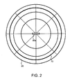
- Fig. 2 shows a schematic diagram of the radiation characteristic of a ⁇ / 2-dipole in a polar diagram, according to a first embodiment of the present invention.
- the radiation characteristic of a ⁇ / 2 dipole applied in a polar coordinate system 80 has a spherical characteristic 70 and depends on the dimensions of the single radiator in relation to the wavelength of the radiated radiation and their shaping can be adjusted by changing the frequency. In the case of the ⁇ / 2 dipole 60a, there is no directivity of the radiation characteristic.
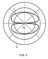
- Fig. 3 shows a schematic diagram of the radiation characteristic of a ⁇ -dipole in a polar diagram, according to a first embodiment of the present invention.
- the radiation characteristic of a ⁇ -dipole shown in a polar coordinate system 80 has a figure-of-eight characteristic 72 and depends on the dimensions of the individual radiator in relation to the wavelength of the radiated radiation and its shaping can be adjusted by changing the frequency.
- a directivity of the emission characteristic is given with emission maxima perpendicular to the dipole axis.
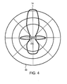
- Fig. 4 shows a schematic diagram of the radiation characteristic of a 3 ⁇ / 2-dipole in a polar diagram, according to a first embodiment of the present invention.
- the emission characteristic of a 3 ⁇ / 2-dipole applied in a polar coordinate system 80 has a lobe characteristic 74 and depends on the design of the single radiator in relation to the wavelength of the emitted radiation and its shaping can be adjusted via a change of the frequency.
- the 3 ⁇ / 2-dipole 60c is a directivity of the radiation characteristic with emission maxima orthogonal and parallel to the dipole axis.
- Fig. 5 shows a schematic representation of a human tissue region and its spatial position to the total electromagnetic field 50, which is generated by three dipole antennas of the electromedical device according to the invention, according to a first embodiment of the present invention.
- a first dipole antenna 94a, a second dipole antenna 94b and a third dipole antenna 94c generate an adapted overall electromagnetic field 50 by superimposing their respective different emission characteristics 96a, 96b, 96c.
- the second dipole antenna 94b is operated as a ⁇ -dipole
- the first dipole antenna 94a and the third dipole antenna 94c are switched as a 3 ⁇ / 2-dipole.
- the field geometry achieved by the adaptation according to the invention can advantageously be predetermined by the outline of the human tissue region 95 to be treated. It goes without saying that, depending on the tissue region, 95 different field geometries are possible by means of different combinations of individual radiators designed for different antennas.
- the performance of the dipole antennas 94a, 94b, 94c is adapted to a desired penetration depth of the total electromagnetic field 50 in the fatty tissue 90 further.
- the total electromagnetic field 50 penetrates through the epidermis 92 without penetrating too deeply into the muscle tissue 91.
Abstract
Description
Die Erfindung betrifft eine elektromedizinische Vorrichtung zum nicht-invasiven Reduzieren oder Entfernen von subkutanem Fettgewebe.The invention relates to an electromedical device for non-invasively reducing or removing subcutaneous adipose tissue.
Überschüssiges Fettgewebe wird bei übergewichtigen Personen heute meist operativ entfernt, beispielsweise durch Fettabsaugen (Liposuktion).Dabei werden Fettzellen der ausgewählten Stellen unter der Haut mittels Hohlnadeln abgesaugt. Solche invasiven Therapieverfahren der plastischen Chirurgie bergen aber immer ein gewisses Risiko, sofern Komplikationen bei der Operation und bei der anschließenden Heilung vorkommen.Excess fat tissue is usually surgically removed in overweight individuals today, for example, by liposuction (liposuction) .Dabei fat cells of the selected sites are sucked under the skin using hollow needles. However, such invasive therapy methods of plastic surgery always carry a certain risk, as long as complications occur during the operation and during the subsequent healing.
Die
Die Druckschrift
Die der vorliegenden Erfindung zugrunde liegende Aufgabe besteht darin, auf einfach Weise überschüssiges subkutanes Fettgewebe nicht-invasiv zu entfernen oder zu reduzieren.The object underlying the present invention is to easily remove or reduce excess subcutaneous adipose tissue non-invasively.
Erfindungsgemäß wird diese Aufgabe durch eine elektromedizinische Vorrichtung mit den Merkmalen des Patentanspruchs 1 gelöst.According to the invention, this object is achieved by an electromedical device having the features of patent claim 1.
Demgemäß ist vorgesehen:
- Eine elektromedizinische Vorrichtung zum nicht-invasiven Reduzieren oder Entfernen von subkutanem Fettgewebe, mit einer Energiequelle, die einen hochfrequenten Wechselstrom bereitstellt, mit zumindest zwei Einzelstrahlern, die von der Energiequelle gespeist sind und die dazu ausgelegt sind, hochfrequente elektromagnetische Wellen in subkutanes Fettgewebe auszustrahlen, und mit einer Richtwirkungs-Steuerung, die mit den Einzelstrahlern gekoppelten ist und die die Einzelstrahler derart ansteuert, dass durch Richtungs- und Feldbündelung der von den jeweiligen Einzelstrahlern ausgesendeten,
hochfrequenten elektromagnetischen Wellen ein elektromagnetisches Gesamtfeld mit einer gewünschten Feldgeometrie in dem subkutanen Fettgewebe erzeugbar ist.
- An electromedical device for non-invasively reducing or removing subcutaneous adipose tissue, comprising: a source of high-frequency alternating current power having at least two individual radiators powered by the energy source and adapted to radiate radio frequency electromagnetic waves into subcutaneous adipose tissue; with a directivity control, with the individual radiators is coupled and controls the individual radiator such that by directional and field focusing emitted by the respective individual radiators,
high-frequency electromagnetic waves, a total electromagnetic field with a desired field geometry in the subcutaneous fatty tissue is generated.
Die der Erfindung zugrunde liegende Idee besteht darin, die einzelnen Einzelstrahler der erfindungsgemäßen elektromedizinischen Vorrichtung auf einfache Weise derart anzusteuern, dass eine bestmögliche Anpassung des elektromagnetischen Gesamtfeldes an die Körperformen der zu behandelnden Personen erfolgen kann. Aufwändige mechanische Einstellvorgänge der elektromedizinischen Vorrichtung sind vorteilhafterweise entbehrlich.The idea underlying the invention is to easily control the individual individual radiators of the electromedical device according to the invention such that the best possible adaptation of the electromagnetic total field to the body shapes of the persons to be treated can take place. Elaborate mechanical adjustment operations of the electromedical device are advantageously dispensable.
Eine kontrollierte und gezielte lokale Gewebeerwärmung führt zu dem gewünschten Reduzieren oder Entfernen von subkutanem Fettgewebe.Controlled and targeted local tissue warming results in the desired reduction or removal of subcutaneous adipose tissue.
Vorteilhafte Ausgestaltungen und Weiterbildungen sind Gegenstand der weiteren Unteransprüche sowie der Beschreibung in Verbindung mit den Figuren der Zeichnung.Advantageous embodiments and further developments are the subject of the other dependent claims and the description in conjunction with the figures of the drawing.
Gemäß einer bevorzugten Weiterbildung weist die elektromedizinische Vorrichtung im Wesentlichen matrixförmig und/oder kaskadenförmig angeordnete Einzelstrahler auf. Bei einer kaskadenförmigen Anordnung der Einzelstrahler ist eine Hintereinanderschaltung oder ein nacheinander Verketten der Einzelstrahler vorgesehen. Bei einer matrixförmigen Anordnung der Einzelstrahler sind die Einzelstrahler arraymäßig, also in Spalten und Zeilen zueinander angeordnet und miteinander verbunden.According to a preferred development, the electromedical device has essentially single-radiators arranged in matrix form and / or in cascade. In a cascade-shaped arrangement of the individual radiators, a series connection or a consecutive linking of the individual radiators is provided. In a matrix-shaped arrangement of the individual radiators, the individual radiators arraymäßig, ie in Columns and rows arranged and interconnected.
Mittels der matrixförmigen bzw. kaskadenförmigen Anordnung der Einzelstrahler ist vorzugsweise die Erzeugung einer Vielzahl verschiedenartig ausgestalteter Feldgeometrien in einfacher Weise möglich. Ferner ist ein prompter und bedarfsgemäßer Wechsel zwischen diesen Feldgeometrien durch eine einfache und angepasste Ansteuerung der Einzelstrahler der elektromedizinischen Vorrichtung möglich.By means of the matrix-shaped or cascade-shaped arrangement of the individual radiators, the generation of a multiplicity of differently designed field geometries is preferably possible in a simple manner. Furthermore, a prompt and appropriate change between these field geometries by a simple and adapted control of the individual radiator of the electromedical device is possible.
Gemäß einer weiteren bevorzugten Ausgestaltung ist mindestens einer der Einzelstrahler als Dipolantenne ausgebildet. Durch die Ausgestaltung des Einzelstrahlers als Dipol kann eine gewünschte Abstrahlgeometrie des Einzelstrahlers bewirkt werden.According to a further preferred embodiment, at least one of the individual radiators is designed as a dipole antenna. Due to the design of the individual radiator as a dipole, a desired emission geometry of the individual radiator can be effected.
Gemäß einem weiteren bevorzugten Ausführungsbeispiel ist mindestens eine der Dipolantennen als λ/2-Dipol oder λ-Dipol ausgebildet. Dadurch können von der Vielzahl der Einzelstrahler der erfindungsgemäßen Vorrichtung jeweils unterschiedliche Einzelgeometrien des elektrischen Feldes erzeugt werden.According to another preferred embodiment, at least one of the dipole antennas is formed as a λ / 2-dipole or λ-dipole. As a result, in each case different individual geometries of the electric field can be generated by the plurality of individual radiators of the device according to the invention.
Gemäß einem weiteren bevorzugten Ausführungsbeispiel ist mindestens einer der Einzelstrahler als Punktstrahler ausgebildet. Dadurch kann ein besonders einfacher und kostengünstiger Aufbau der elektromedizinischen Vorrichtung realisiert werden.According to a further preferred embodiment, at least one of the individual radiators is designed as a spot radiator. As a result, a particularly simple and cost-effective design of the electromedical device can be realized.
Gemäß einem weiteren bevorzugten Ausführungsbeispiel sind die jeweiligen Einzelstrahler derart ausgerichtet, dass die Einzelstrahler die von ihnen erzeugten elektromagnetischen Wellen jeweils in dieselbe Richtung ausstrahlen. Insbesondere kann so sichergestellt werden, dass die Einzelstrahler das ausgestrahlte elektromagnetische Feld in die Richtung des Körpers einer zu behandelnden Person ausstrahlt. Dieselbe Richtung ist damit dadurch vergeben, wie und auf welche Weise die Person von der erfindungsgemäßen Vorrichtung appliziert wird, d. h. an die Person angelegt wird. Die Richtung dieses Anlegens der Vorrichtung bestimmt damit auch die vorgegebene Richtung.According to a further preferred embodiment, the respective individual radiators are aligned such that the individual radiators generate the electromagnetic waves generated by them each in the same direction. In particular, it can thus be ensured that the individual radiator emits the emitted electromagnetic field in the direction of the body of a person to be treated. The same direction is thus awarded by how and in what way the person is applied by the device according to the invention, that is applied to the person. The direction of this application of the device thus determines the predetermined direction.
Gemäß einem weiteren bevorzugten Ausführungsbeispiel ist die Steuereinrichtung dazu ausgelegt, die Frequenzen und/oder die Amplitude und/oder die Leistung der ausgestrahlten elektromagnetischen Wellen eines Einzelstrahlers zu verändern.According to a further preferred embodiment, the control device is designed to change the frequencies and / or the amplitude and / or the power of the emitted electromagnetic waves of a single radiator.
Wie bereits oben ausgeführt, wird durch die erfindungsgemäße Vorrichtung das elektromagnetische Feld variiert. Dabei wird das elektromagnetische Feld insbesondere im Hinblick auf seine Intensität und Ausdehnung sowie seine Homogenität verändert. Diese Veränderung lässt sich auf einfache Weise über eine Variation der Frequenz, der Amplitude und/oder der Leistung der ausgestrahlten elektromagnetischen Wellen des Einzelstrahlers verändern. Auf diese Weise kann je nachdem in welcher Tiefe das subkutane Fettgewebe im Körper einer zu behandelnden Person vorhanden ist sowie welche Dichte und welche Konsistenz dieses Fettgewebe aufweist, das elektromagnetische Feld eben genau angepasst werden.As already stated above, the electromagnetic field is varied by the device according to the invention. In this case, the electromagnetic field is changed in particular with regard to its intensity and extent and its homogeneity. This change can be changed in a simple manner via a variation of the frequency, the amplitude and / or the power of the emitted electromagnetic waves of the individual radiator. In this way, depending on the depth at which the subcutaneous fatty tissue is present in the body of a person to be treated, as well as the density and consistency of this fatty tissue, the electromagnetic field can be exactly adjusted.
Gemäß einem weiteren bevorzugten Ausführungsbeispiel weist die Steuereinrichtungen zumindest ein Laufzeitglied auf. Ein jeweiliges Laufzeitglied ist dazu eingerichtet, das von einem Einzelstrahler erzeugte elektromagnetische Feld durch eine Änderung einer jeweiligen Signallaufzeit des Steuersignals zu verändern. Durch Variation und geeignete Anpassung der Signallaufzeiten der verschiedenen Einzelstrahler lässt sich so das elektromagnetische Gesamtfeld bedarfsmäßig einstellen.According to a further preferred embodiment, the control devices on at least one delay element. A respective delay element is adapted to the electromagnetic field generated by a single radiator by a Changing a respective signal propagation time of the control signal to change. By varying and suitably adapting the signal propagation times of the various individual emitters, the total electromagnetic field can be adjusted as required.
Gemäß einem weiteren bevorzugten Ausführungsbeispiel weist ein Steuerglied zumindest einen Phasenschieber auf. Ein jeweiliger Phasenschieber ist dazu eingerichtet, das jeweilige elektromagnetische Feld der Einzelstrahler durch eine Änderung seiner jeweiligen Phase zu verändern. Auch durch diese Maßnahme lässt sich eine bedarfsmäßige Geometrieänderung des elektromagnetischen Gesamtfeldes bewirken.According to a further preferred embodiment, a control element has at least one phase shifter. A respective phase shifter is set up to change the respective electromagnetic field of the individual radiators by changing its respective phase. This measure also makes it possible to effect a change in the geometry of the electromagnetic total field as required.
Gemäß einem weiteren bevorzugten Ausführungsbeispiel ist die Vorrichtung dazu ausgelegt ist, im Frequenzbereich zwischen 0,4-61,5 GHz, vorzugsweise zwischen 1,0-7,5 GHz, und besonders bevorzugt zwischen 1,6-5,9 GHz, und insbesondere zwischen 2,4-2,5 GHz zu arbeiten. Durch die Verwendungen unterschiedlicher Frequenzbereiche kann im Sinne der Fettentfernung oder Fettreduzierung eine solche Strahlung verwendet werden, die ein bestmögliches Absorptionsverhalten der Strahlung im zu behandelnden Bereich erzielt.According to a further preferred embodiment, the device is designed in the frequency range between 0.4-61.5 GHz, preferably between 1.0-7.5 GHz, and particularly preferably between 1.6-5.9 GHz, and in particular to work between 2.4-2.5 GHz. By the use of different frequency ranges, in the sense of fat removal or fat reduction, such a radiation can be used which achieves the best possible absorption behavior of the radiation in the area to be treated.
Die obigen Ausgestaltungen und Weiterbildungen lassen sich, sofern sinnvoll, beliebig miteinander kombinieren. Weitere mögliche Ausgestaltungen, Weiterbildungen und Implementierungen der Erfindung umfassen auch nicht explizit genannte Kombinationen von zuvor oder im Folgenden bezüglich der Ausführungsbeispiele beschriebenen Merkmale der Erfindung. Insbesondere wird der Fachmann auch Einzelaspekte als Verbesserungen oder Ergänzungen zu der jeweiligen Grundform der vorliegenden Erfindung hinzufügen.The above embodiments and developments can, if appropriate, combine with each other as desired. Further possible refinements, developments and implementations of the invention also include combinations, not explicitly mentioned, of features of the invention described above or below with regard to the exemplary embodiments. In particular, the person skilled in the art will also add individual aspects as improvements or additions to the respective basic form of the present invention.
Die vorliegende Erfindung wird nachfolgend anhand der in den schematischen Figuren der Zeichnungen angegebenen Ausführungsbeispiele näher erläutert. Dabei zeigen:
-
Fig. 1a eine schematische Darstellung eines Ausführungsbeispiels einer erfindungsgemäßen Vorrichtung; -
Fig. 1b eine schematische Darstellung eines weiteren Ausführungsbeispiels einer erfindungsgemäßen Vorrichtung; -
Fig. 2 die Abstrahlcharakteristik eines λ/2-Dipols in einem Polardiagramm, wie es mittels einer erfindungsgemäßen Vorrichtung erzeugt wird; -
Fig. 3 die Abstrahlcharakteristik eines λ-Dipols in einem Polardiagramm, wie es mittels einer erfindungsgemäßen Vorrichtung erzeugt wird; -
Fig. 4 die Abstrahlcharakteristik eines 3λ/2-Dipols in einem Polardiagramm, wie es mittels einer erfindungsgemäßen Vorrichtung erzeugt wird; -
Fig. 5 eine Darstellung eines menschlichen Gewebebereichs und seine räumliche Lage zu einem elektromagnetischen Gesamtfeld, welches von drei Dipolantennen der erfindungsgemäßen Vorrichtung erzeugt wird.
-
Fig. 1a a schematic representation of an embodiment of a device according to the invention; -
Fig. 1b a schematic representation of another embodiment of a device according to the invention; -
Fig. 2 the radiation characteristic of a λ / 2 dipole in a polar diagram, as it is generated by means of a device according to the invention; -
Fig. 3 the radiation characteristic of a λ-dipole in a polar diagram, as it is generated by means of a device according to the invention; -
Fig. 4 the radiation characteristic of a 3λ / 2 dipole in a polar diagram, as it is generated by means of a device according to the invention; -
Fig. 5 a representation of a human tissue region and its spatial position to a total electromagnetic field, which is generated by three dipole antennas of the device according to the invention.
In den Figuren bezeichnen dieselben Bezugszeichen gleiche oder funktionsgleiche Elemente, Signale und Komponenten - sofern nichts Gegenteiliges angegeben ist.In the figures, the same reference numerals designate the same or functionally identical elements, signals and components - unless stated otherwise.
Die elektromedizinische Vorrichtung 5 umfasst einen Basisteil 6, welcher eine Richtwirkungs-Steuerung 10 und eine Energiequelle 11 umfasst. Ferner umfasst die elektromedizinische Vorrichtung 5 einen Erweiterungsteil 8, welcher mit variabler Zusammensetzung seines beispielsweise kaskaden- oder matrixförmig ausgestalteten Aufbaus aus weiteren Untereinrichtungen zusammengesetzt.The
Die Richtwirkungs-Steuerung 10 ist zum einen mit der Energiequelle 11 elektrisch verbunden und zum anderen beispielsweise mit einem ersten Steuerglied 12. Das erste Steuerglied 12 ist ferner über eine erste Steuereinrichtung 14 an einen ersten Einzelstrahler 32 gekoppelt. Ferner ist an der erste Steuereinrichtung 14 auch ein zweites Steuerglied 16 angeschlossen, welches wiederum mit einer zweiten Steuereinrichtung 18 gekoppelt ist. Die zweite Steuereinrichtung 18 besitzt neben dieser Verbindung zum einen eine Verbindung mit einem zweiten Einzelstrahler 34 und zum anderen mit einem dritten Steuerglied 20. Das dritte Steuerglied 20 ist ferner mit einer dritten Steuereinrichtung 22 verbunden und die dritte Steuereinrichtung 22 ist darüber hinaus mit einem dritten Einzelstrahler 36 und mit einem vierten Steuerglied 24 gekoppelt. Das vierte Steuerglied 24 ist dann wiederum mit einer vierten Steuereinrichtung 26 verbunden. Die vierte Steuereinrichtung 26 ist mit einem vierten Einzelstrahler 38 verbunden. In
Die Energiequelle 11 versorgt über die Richtwirkungs-Steuerung 10 die elektromedizinische Vorrichtung 5 mit Energie. Die Richtwirkungs-Steuerung 10 speist ferner ein hochfrequentes Signal in das erste Steuerglied 12 ein. Das erste Steuerglied 12 speist dann ein hochfrequentes Signal in die erste Steuereinrichtung 14 ein, in welcher das hochfrequente Signal geteilt wird. Ein erster Teil des hochfrequenten Signals ist zur Abstrahlung über den ersten Einzelstrahler 32 vorgesehen. Ein zweiter Teil des hochfrequenten Signals wird von der ersten Steuereinrichtung 14 über das zweite Steuerglied 16 in die zweite Steuereinrichtung 18 eingespeist, in welcher wiederum eine Teilung in einen zur Abstrahlung über den zweiten Einzelstrahler 34 vorgesehenen Teil und in einen zur Weiterleitung zu dem dirtten Steuerglied 20 vorgesehen Teil erfolgt. Das dritte Steuerglied 20 speist das hochfrequente Signal weiter in die dritte Steuereinrichtung 22 ein. Die dritte Steuereinrichtung speist ein Signal zur Abstrahlung in den dritten Einzelstrahler 36 ein und leitet ferner ein Signal zu dem vierten Steuerglied 24 weiter. Das vierte Steuerglied 24 versorgt die vierte Steuereinrichtung 26, welche den vierten Einzelstrahler 38 zur Abstrahlung speist.The
Durch die vorliegende Kaskadierung der Steuerglieder 12, 16, 20, 24 und der Steuereinrichtungen 14, 18, 22, 26 wird jeder Einzelstrahler 32, 34, 36, 38 einzeln mit einem steuerbaren und insbesondere in der Phase und Frequenz variablen, hochfrequenten Signal versorgt. Diese Kaskadierung von Steuergliedern und Steuereinrichtungen im Zusammenspiel mit der Richtwirkungs-Steuerung 10 ermöglicht die erfindungsgemäße Ausbildung einer gewünschten Feldgeometrie des elektromagnetischen Gesamtfeldes 50, welches durch Überlagerung der von den jeweiligen Einzelstrahlern 32, 34, 36, 38 abgestrahlten elektromagnetischen Felder 42, 44, 46, 48 entsteht.By the present cascading of the
Die Einzelstrahler 32, 34, 36, 38 können dabei jeweils als Dipolantenne ausgebildet sein, insbesondere als λ/2-Dipolantenne, als λ-Dipolantenne oder als 3λ/2-Dipolantenne. Die Abstrahlcharakteristiken derartiger beispielhafter Antennenformen für die Einzelstrahler werden weiter unten in Bezug auf die
Das erste Steuerglied 12 kann beispielsweise ein Laufzeitglied und/oder einen Phasenschieber umfassen, wobei das Laufzeitglied zur Laufzeitänderung des eingespeisten hochfrequenten Signals bestimmt ist und der Phasenschieber zur Phasenänderung des eingespeisten hochfrequenten Signals ausgelegt ist. Analoges gilt für die Steuerglieder 16, 20 und 24.The
Die Steuereinrichtungen 14, 18, 22, 26 sind mit den Einzelstrahlern 32, 34, 36, 38 gekoppelt. Ferner sind die Steuereinrichtungen 14, 18, 22, 26 vorzugsweise dazu bestimmt, die an die Einzelstrahler eingespeisten hochfrequenten Signale bezüglich ihrer Frequenz und/oder Leistung ändern zu können.
Die in einem Polarkoordinatensystem 80 aufgetragene Abstrahlcharakteristik eines λ/2-Dipols weist eine Kugelcharakteristik 70 auf und hängt von den Abmessungen des Einzelstrahlers im Verhältnis zur Wellenlänge der abgestrahlten Strahlung ab und ihre Formung kann über eine Veränderung der Frequenz eingestellt werden. Im Fall des λ/2-Dipols 60a ist keine Richtwirkung der Abstrahlcharakteristik gegeben.The radiation characteristic of a λ / 2 dipole applied in a polar coordinate
Die in einem Polarkoordinatensystem 80 aufgezeigte Abstrahlcharakteristik eines λ-Dipols weist eine Achtercharakteristik 72 auf und hängt von den Abmessungen des Einzelstrahlers im Verhältnis zur Wellenlänge der abgestrahlten Strahlung ab und ihre Formung kann über eine Veränderung der Frequenz eingestellt werden. Im Fall des λ-Dipols 60b ist eine Richtwirkung der Abstrahlcharakteristik mit Abstrahlmaxima senkrecht zur Dipolachse gegeben.The radiation characteristic of a λ-dipole shown in a polar coordinate
Wie der
Eine erste Dipolantenne 94a, eine zweite Dipolantenne 94b und eine dritte Dipolantenne 94c erzeugen durch die Überlagerung ihrer jeweilig unterschiedlichen Abstrahlcharakteristika 96a, 96b, 96c ein angepasstes elektromagnetisches Gesamtfeld 50. In der gezeigten Ausführungsform gemäß
Wie aus
- elektromedizinische Vorrichtungelectromedical device
- 55
- Basisteilbase
- 66
- Erweiterungsteilextension part
- 88th
- Richtwirkungs-SteuerungDirectivity control
- 1010
- Energiequelleenergy
- 1111
- Steuereinrichtungcontrol device
- 14, 18, 22, 2614, 18, 22, 26
- Steuergliedcontrol member
- 12, 16, 20, 2412, 16, 20, 24
- erster Einzelstrahlerfirst single radiator
- 3232
- zweiter Einzelstrahlersecond single emitter
- 3434
- dritter Einzelstrahlerthird single radiator
- 3636
- vierter Einzelstrahlerfourth single radiator
- 3838
- elektromagnetisches Feldelectromagnetic field
- 42, 44, 46, 4842, 44, 46, 48
- elektromagnetisches Gesamtfeldtotal electromagnetic field
- 5050
- λ/2-Dipolλ / 2 dipole
- 60a60a
- λ-Dipolλ dipole
- 60b60b
- 3λ/2-Dipol3λ / 2 dipole
- 60c60c
- Kugelcharakteristikomnidirectional
- 7070
- AchtercharakteristikBidirectional
- 7272
- Keulencharakteristiklobar
- 7474
- PolarkoordinatensystemPolar coordinate system
- 8080
- Fettgewebeadipose tissue
- 9090
- Muskelgewebemuscle tissue
- 9191
- Epidermisepidermis
- 9292
- erste Dipolantennefirst dipole antenna
- 94a94a
- zweite Dipolantennesecond dipole antenna
- 94b94b
- dritte Dipolantennethird dipole antenna
- 94c94c
- menschlicher Gewebebereichhuman tissue area
- 9595
- erste Abstrahlcharakteristikfirst emission characteristic
- 96a96a
- zweite Abstrahlcharakteristiksecond emission characteristic
- 96b96b
- dritte Abstrahlcharakteristikthird emission characteristic
- 96c96c
Claims (11)
Applications Claiming Priority (1)
| Application Number | Priority Date | Filing Date | Title |
|---|---|---|---|
| DE102010041649A DE102010041649A1 (en) | 2010-09-29 | 2010-09-29 | Electromedical device for non-invasively reducing or removing subcutaneous adipose tissue |
Publications (1)
| Publication Number | Publication Date |
|---|---|
| EP2436331A1 true EP2436331A1 (en) | 2012-04-04 |
Family
ID=44719462
Family Applications (1)
| Application Number | Title | Priority Date | Filing Date |
|---|---|---|---|
| EP11182538A Withdrawn EP2436331A1 (en) | 2010-09-29 | 2011-09-23 | Electromedical device for the non-invasive reduction or removal of subcutaneous adipose tissue |
Country Status (6)
| Country | Link |
|---|---|
| US (1) | US8744594B2 (en) |
| EP (1) | EP2436331A1 (en) |
| JP (2) | JP2012071134A (en) |
| KR (1) | KR101302814B1 (en) |
| DE (1) | DE102010041649A1 (en) |
| IL (1) | IL215406A0 (en) |
Families Citing this family (2)
| Publication number | Priority date | Publication date | Assignee | Title |
|---|---|---|---|---|
| JP6331550B2 (en) | 2014-03-25 | 2018-05-30 | 株式会社デンソー | Integrated device |
| FR3099705A1 (en) * | 2019-08-05 | 2021-02-12 | Biopass | Device for the emission of a magnetic field |
Citations (3)
| Publication number | Priority date | Publication date | Assignee | Title |
|---|---|---|---|---|
| US5143063A (en) | 1988-02-09 | 1992-09-01 | Fellner Donald G | Method of removing adipose tissue from the body |
| US5507790A (en) | 1994-03-21 | 1996-04-16 | Weiss; William V. | Method of non-invasive reduction of human site-specific subcutaneous fat tissue deposits by accelerated lipolysis metabolism |
| US20090221999A1 (en) * | 2008-02-29 | 2009-09-03 | Ramin Shahidi | Thermal Ablation Design and Planning Methods |
Family Cites Families (9)
| Publication number | Priority date | Publication date | Assignee | Title |
|---|---|---|---|---|
| JPH01115370A (en) * | 1987-10-28 | 1989-05-08 | Fumiaki Okada | Applicator for hyperthermia |
| ATE298536T1 (en) * | 1999-03-09 | 2005-07-15 | Thermage Inc | DEVICE FOR TREATING TISSUE |
| US6463336B1 (en) * | 1999-04-01 | 2002-10-08 | Mmtc, Inc | Active bandage suitable for applying pulsed radio-frequencies or microwaves to the skin for medical purposes |
| US20060265034A1 (en) * | 2005-04-05 | 2006-11-23 | Ams Medical Sa | Microwave devices for treating biological samples and tissue and methods for using same |
| WO2007141874A1 (en) * | 2006-06-09 | 2007-12-13 | Medical Appliance Co., Ltd. | Sharp pain treatment device, high frequency treatment device |
| US8700176B2 (en) * | 2006-07-27 | 2014-04-15 | Pollogen Ltd. | Apparatus and method for non-invasive treatment of skin tissue |
| GB0624584D0 (en) * | 2006-12-08 | 2007-01-17 | Medical Device Innovations Ltd | Skin treatment apparatus and method |
| US20120143178A9 (en) | 2007-06-15 | 2012-06-07 | Primaeva Medical, Inc. | Devices and methods for percutaneous energy delivery |
| KR101654863B1 (en) | 2007-12-12 | 2016-09-22 | 미라마 랩스 인코포레이티드 | Systems, apparatus, methods and procedures for the noninvasive treatment of tissue using microwave energy |
-
2010
- 2010-09-29 DE DE102010041649A patent/DE102010041649A1/en not_active Withdrawn
-
2011
- 2011-09-23 EP EP11182538A patent/EP2436331A1/en not_active Withdrawn
- 2011-09-27 IL IL215406A patent/IL215406A0/en unknown
- 2011-09-27 JP JP2011211093A patent/JP2012071134A/en active Pending
- 2011-09-29 KR KR1020110099060A patent/KR101302814B1/en not_active IP Right Cessation
- 2011-09-29 US US13/248,163 patent/US8744594B2/en not_active Expired - Fee Related
-
2013
- 2013-12-24 JP JP2013266137A patent/JP2014061443A/en not_active Withdrawn
Patent Citations (3)
| Publication number | Priority date | Publication date | Assignee | Title |
|---|---|---|---|---|
| US5143063A (en) | 1988-02-09 | 1992-09-01 | Fellner Donald G | Method of removing adipose tissue from the body |
| US5507790A (en) | 1994-03-21 | 1996-04-16 | Weiss; William V. | Method of non-invasive reduction of human site-specific subcutaneous fat tissue deposits by accelerated lipolysis metabolism |
| US20090221999A1 (en) * | 2008-02-29 | 2009-09-03 | Ramin Shahidi | Thermal Ablation Design and Planning Methods |
Also Published As
| Publication number | Publication date |
|---|---|
| US20120078326A1 (en) | 2012-03-29 |
| KR101302814B1 (en) | 2013-09-02 |
| IL215406A0 (en) | 2012-04-30 |
| US8744594B2 (en) | 2014-06-03 |
| JP2014061443A (en) | 2014-04-10 |
| KR20120033287A (en) | 2012-04-06 |
| JP2012071134A (en) | 2012-04-12 |
| DE102010041649A1 (en) | 2012-03-29 |
Similar Documents
| Publication | Publication Date | Title |
|---|---|---|
| DE60312597T2 (en) | System for irradiation with charged particles | |
| DE10310765A1 (en) | Medical thermotherapy instrument, e.g. for treatment of benign prostatic hypertrophy (BPH), has an antenna that can be set to radiate at least two different frequency microwave signals | |
| EP2022534B1 (en) | Control device for controlling an irradiation procedure, particle therapy facility and method for irradiating a target volume | |
| DE60123790T2 (en) | ASYMMETRIC TRANSMISSION SYSTEM FOR RADIOELECTRIC THERAPY | |
| DE102018004568B4 (en) | Radiation source for microwave pulses and radiation device | |
| EP2016979B1 (en) | Particle beam application device, beam emitting device and method for guiding a particle beam | |
| DE60206881T2 (en) | ULTRASOUND TRANSFORMER AND METHOD FOR PRODUCING AN ULTRASOUND TRANSFORMER | |
| DE69927383T2 (en) | METHOD FOR THE COSMETIC TREATMENT OF THE SKIN AND THE HEADACHE WITH ELECTROMAGNETIC WAVES AND ETHERIC OILS | |
| DE102018211931A1 (en) | Mode swirling device | |
| EP3031439B1 (en) | System for generating ultrasonic waves | |
| EP2436331A1 (en) | Electromedical device for the non-invasive reduction or removal of subcutaneous adipose tissue | |
| DE112018005767T5 (en) | Device for the treatment of tumors using evanescent waves | |
| DE3930930C1 (en) | ||
| EP3161903B1 (en) | Antenna with adjustable beam pattern and method of operation thereof | |
| EP2397809A2 (en) | Method and assembly for the generation of high energy microwave impulses | |
| EP3685425A1 (en) | Device for treating a product with microwaves | |
| DE8226546U1 (en) | DEVICE FOR IMPACTING THE TISSUE OF A PATIENT WITH A HIGH-FREQUENCY ELECTROMAGNETIC FIELD TO PROMOTE HEALING | |
| DE112010002639B4 (en) | ANTENNA DEVICE | |
| WO2011107313A1 (en) | Irradiation apparatus and irradiation method for depositing a dose in a target volume | |
| EP3996206B1 (en) | Horn antenna and reconstruction thereof | |
| DE3721271A1 (en) | METHOD AND DEVICE FOR TREATING VARIOUS DISEASES | |
| DE202017104399U1 (en) | Resonator with three-stage structure for approach detection of biological waves | |
| DE102017121731A1 (en) | Apparatus for treating a product with microwaves | |
| AT399280B (en) | DEVICE FOR HEAT TREATING TUMORS | |
| DE102011055345A1 (en) | Apparatus for the therapy of tumors |
Legal Events
| Date | Code | Title | Description |
|---|---|---|---|
| PUAI | Public reference made under article 153(3) epc to a published international application that has entered the european phase |
Free format text: ORIGINAL CODE: 0009012 |
|
| AK | Designated contracting states |
Kind code of ref document: A1 Designated state(s): AL AT BE BG CH CY CZ DE DK EE ES FI FR GB GR HR HU IE IS IT LI LT LU LV MC MK MT NL NO PL PT RO RS SE SI SK SM TR |
|
| AX | Request for extension of the european patent |
Extension state: BA ME |
|
| 17P | Request for examination filed |
Effective date: 20120329 |
|
| 17Q | First examination report despatched |
Effective date: 20120704 |
|
| GRAP | Despatch of communication of intention to grant a patent |
Free format text: ORIGINAL CODE: EPIDOSNIGR1 |
|
| INTG | Intention to grant announced |
Effective date: 20140411 |
|
| STAA | Information on the status of an ep patent application or granted ep patent |
Free format text: STATUS: THE APPLICATION IS DEEMED TO BE WITHDRAWN |
|
| 18D | Application deemed to be withdrawn |
Effective date: 20140822 |