EP2380518A2 - Dual-purpose lasso catheter with irrigation using circumferentially arranged ring bump electrodes - Google Patents
Dual-purpose lasso catheter with irrigation using circumferentially arranged ring bump electrodes Download PDFInfo
- Publication number
- EP2380518A2 EP2380518A2 EP11163281A EP11163281A EP2380518A2 EP 2380518 A2 EP2380518 A2 EP 2380518A2 EP 11163281 A EP11163281 A EP 11163281A EP 11163281 A EP11163281 A EP 11163281A EP 2380518 A2 EP2380518 A2 EP 2380518A2
- Authority
- EP
- European Patent Office
- Prior art keywords
- catheter
- distal
- electrodes
- catheter according
- breach hole
- Prior art date
- Legal status (The legal status is an assumption and is not a legal conclusion. Google has not performed a legal analysis and makes no representation as to the accuracy of the status listed.)
- Granted
Links
- 230000002262 irrigation Effects 0.000 title description 3
- 238000003973 irrigation Methods 0.000 title description 3
- 210000002216 heart Anatomy 0.000 claims abstract description 28
- 239000012530 fluid Substances 0.000 claims abstract description 20
- 238000004891 communication Methods 0.000 claims abstract description 10
- 238000003780 insertion Methods 0.000 claims description 12
- 230000037431 insertion Effects 0.000 claims description 12
- BASFCYQUMIYNBI-UHFFFAOYSA-N platinum Chemical compound [Pt] BASFCYQUMIYNBI-UHFFFAOYSA-N 0.000 claims description 8
- KDLHZDBZIXYQEI-UHFFFAOYSA-N Palladium Chemical compound [Pd] KDLHZDBZIXYQEI-UHFFFAOYSA-N 0.000 claims description 4
- 229910052697 platinum Inorganic materials 0.000 claims description 4
- 210000004204 blood vessel Anatomy 0.000 claims description 2
- 229910052741 iridium Inorganic materials 0.000 claims description 2
- GKOZUEZYRPOHIO-UHFFFAOYSA-N iridium atom Chemical compound [Ir] GKOZUEZYRPOHIO-UHFFFAOYSA-N 0.000 claims description 2
- 229910052763 palladium Inorganic materials 0.000 claims description 2
- 230000001419 dependent effect Effects 0.000 claims 2
- 238000002679 ablation Methods 0.000 abstract description 16
- 238000013507 mapping Methods 0.000 abstract description 8
- 230000000747 cardiac effect Effects 0.000 abstract description 7
- 238000000034 method Methods 0.000 description 18
- 210000003492 pulmonary vein Anatomy 0.000 description 9
- 210000005003 heart tissue Anatomy 0.000 description 8
- 239000000523 sample Substances 0.000 description 8
- 210000001519 tissue Anatomy 0.000 description 7
- 230000002159 abnormal effect Effects 0.000 description 6
- 206010003119 arrhythmia Diseases 0.000 description 6
- 210000005242 cardiac chamber Anatomy 0.000 description 5
- 230000000694 effects Effects 0.000 description 5
- 230000006793 arrhythmia Effects 0.000 description 4
- 210000003462 vein Anatomy 0.000 description 4
- 238000003491 array Methods 0.000 description 3
- 230000005672 electromagnetic field Effects 0.000 description 3
- 230000033001 locomotion Effects 0.000 description 3
- 230000007246 mechanism Effects 0.000 description 3
- 230000037361 pathway Effects 0.000 description 3
- FAPWRFPIFSIZLT-UHFFFAOYSA-M Sodium chloride Chemical compound [Na+].[Cl-] FAPWRFPIFSIZLT-UHFFFAOYSA-M 0.000 description 2
- 230000004913 activation Effects 0.000 description 2
- 230000003126 arrythmogenic effect Effects 0.000 description 2
- 229910003460 diamond Inorganic materials 0.000 description 2
- 239000010432 diamond Substances 0.000 description 2
- 238000002955 isolation Methods 0.000 description 2
- 210000005246 left atrium Anatomy 0.000 description 2
- 230000003902 lesion Effects 0.000 description 2
- 239000000463 material Substances 0.000 description 2
- 238000005259 measurement Methods 0.000 description 2
- HLXZNVUGXRDIFK-UHFFFAOYSA-N nickel titanium Chemical compound [Ti].[Ti].[Ti].[Ti].[Ti].[Ti].[Ti].[Ti].[Ti].[Ti].[Ti].[Ni].[Ni].[Ni].[Ni].[Ni].[Ni].[Ni].[Ni].[Ni].[Ni].[Ni].[Ni].[Ni].[Ni] HLXZNVUGXRDIFK-UHFFFAOYSA-N 0.000 description 2
- 229910001000 nickel titanium Inorganic materials 0.000 description 2
- 229920002635 polyurethane Polymers 0.000 description 2
- 239000004814 polyurethane Substances 0.000 description 2
- 230000008569 process Effects 0.000 description 2
- 238000012545 processing Methods 0.000 description 2
- 230000033764 rhythmic process Effects 0.000 description 2
- 238000002604 ultrasonography Methods 0.000 description 2
- 230000002792 vascular Effects 0.000 description 2
- 206010001497 Agitation Diseases 0.000 description 1
- 206010003658 Atrial Fibrillation Diseases 0.000 description 1
- 230000005355 Hall effect Effects 0.000 description 1
- 238000004458 analytical method Methods 0.000 description 1
- 210000003484 anatomy Anatomy 0.000 description 1
- 238000005452 bending Methods 0.000 description 1
- 230000015572 biosynthetic process Effects 0.000 description 1
- 230000008859 change Effects 0.000 description 1
- 238000004590 computer program Methods 0.000 description 1
- 238000001816 cooling Methods 0.000 description 1
- 210000003748 coronary sinus Anatomy 0.000 description 1
- 230000002950 deficient Effects 0.000 description 1
- 210000001174 endocardium Anatomy 0.000 description 1
- 238000011156 evaluation Methods 0.000 description 1
- 239000003292 glue Substances 0.000 description 1
- 238000010438 heat treatment Methods 0.000 description 1
- 238000003384 imaging method Methods 0.000 description 1
- 238000004519 manufacturing process Methods 0.000 description 1
- 238000012986 modification Methods 0.000 description 1
- 230000004048 modification Effects 0.000 description 1
- 210000004165 myocardium Anatomy 0.000 description 1
- XEPXGZZWVKNRGS-GQYPCLOQSA-N n-[(3r,4s,5s,6r)-3,4,5-trihydroxy-6-(hydroxymethyl)oxan-2-yl]octanamide Chemical compound CCCCCCCC(=O)NC1O[C@H](CO)[C@@H](O)[C@H](O)[C@H]1O XEPXGZZWVKNRGS-GQYPCLOQSA-N 0.000 description 1
- RVTZCBVAJQQJTK-UHFFFAOYSA-N oxygen(2-);zirconium(4+) Chemical compound [O-2].[O-2].[Zr+4] RVTZCBVAJQQJTK-UHFFFAOYSA-N 0.000 description 1
- 229920003023 plastic Polymers 0.000 description 1
- 239000004033 plastic Substances 0.000 description 1
- 230000001681 protective effect Effects 0.000 description 1
- 230000002685 pulmonary effect Effects 0.000 description 1
- 238000007674 radiofrequency ablation Methods 0.000 description 1
- 230000002787 reinforcement Effects 0.000 description 1
- 230000004044 response Effects 0.000 description 1
- 239000011780 sodium chloride Substances 0.000 description 1
- 230000001225 therapeutic effect Effects 0.000 description 1
- 230000000007 visual effect Effects 0.000 description 1
Images


Classifications
-
- A—HUMAN NECESSITIES
- A61—MEDICAL OR VETERINARY SCIENCE; HYGIENE
- A61B—DIAGNOSIS; SURGERY; IDENTIFICATION
- A61B18/00—Surgical instruments, devices or methods for transferring non-mechanical forms of energy to or from the body
- A61B18/04—Surgical instruments, devices or methods for transferring non-mechanical forms of energy to or from the body by heating
- A61B18/12—Surgical instruments, devices or methods for transferring non-mechanical forms of energy to or from the body by heating by passing a current through the tissue to be heated, e.g. high-frequency current
- A61B18/14—Probes or electrodes therefor
- A61B18/1492—Probes or electrodes therefor having a flexible, catheter-like structure, e.g. for heart ablation
-
- A—HUMAN NECESSITIES
- A61—MEDICAL OR VETERINARY SCIENCE; HYGIENE
- A61B—DIAGNOSIS; SURGERY; IDENTIFICATION
- A61B18/00—Surgical instruments, devices or methods for transferring non-mechanical forms of energy to or from the body
- A61B18/18—Surgical instruments, devices or methods for transferring non-mechanical forms of energy to or from the body by applying electromagnetic radiation, e.g. microwaves
-
- A—HUMAN NECESSITIES
- A61—MEDICAL OR VETERINARY SCIENCE; HYGIENE
- A61B—DIAGNOSIS; SURGERY; IDENTIFICATION
- A61B5/00—Measuring for diagnostic purposes; Identification of persons
- A61B5/06—Devices, other than using radiation, for detecting or locating foreign bodies ; determining position of probes within or on the body of the patient
- A61B5/061—Determining position of a probe within the body employing means separate from the probe, e.g. sensing internal probe position employing impedance electrodes on the surface of the body
- A61B5/062—Determining position of a probe within the body employing means separate from the probe, e.g. sensing internal probe position employing impedance electrodes on the surface of the body using magnetic field
-
- A—HUMAN NECESSITIES
- A61—MEDICAL OR VETERINARY SCIENCE; HYGIENE
- A61B—DIAGNOSIS; SURGERY; IDENTIFICATION
- A61B5/00—Measuring for diagnostic purposes; Identification of persons
- A61B5/24—Detecting, measuring or recording bioelectric or biomagnetic signals of the body or parts thereof
- A61B5/25—Bioelectric electrodes therefor
- A61B5/279—Bioelectric electrodes therefor specially adapted for particular uses
- A61B5/28—Bioelectric electrodes therefor specially adapted for particular uses for electrocardiography [ECG]
- A61B5/283—Invasive
- A61B5/287—Holders for multiple electrodes, e.g. electrode catheters for electrophysiological study [EPS]
-
- A—HUMAN NECESSITIES
- A61—MEDICAL OR VETERINARY SCIENCE; HYGIENE
- A61B—DIAGNOSIS; SURGERY; IDENTIFICATION
- A61B5/00—Measuring for diagnostic purposes; Identification of persons
- A61B5/68—Arrangements of detecting, measuring or recording means, e.g. sensors, in relation to patient
- A61B5/6846—Arrangements of detecting, measuring or recording means, e.g. sensors, in relation to patient specially adapted to be brought in contact with an internal body part, i.e. invasive
- A61B5/6847—Arrangements of detecting, measuring or recording means, e.g. sensors, in relation to patient specially adapted to be brought in contact with an internal body part, i.e. invasive mounted on an invasive device
- A61B5/6852—Catheters
- A61B5/6855—Catheters with a distal curved tip
-
- A—HUMAN NECESSITIES
- A61—MEDICAL OR VETERINARY SCIENCE; HYGIENE
- A61B—DIAGNOSIS; SURGERY; IDENTIFICATION
- A61B5/00—Measuring for diagnostic purposes; Identification of persons
- A61B5/68—Arrangements of detecting, measuring or recording means, e.g. sensors, in relation to patient
- A61B5/6846—Arrangements of detecting, measuring or recording means, e.g. sensors, in relation to patient specially adapted to be brought in contact with an internal body part, i.e. invasive
- A61B5/6847—Arrangements of detecting, measuring or recording means, e.g. sensors, in relation to patient specially adapted to be brought in contact with an internal body part, i.e. invasive mounted on an invasive device
- A61B5/6852—Catheters
- A61B5/6856—Catheters with a distal loop
-
- A—HUMAN NECESSITIES
- A61—MEDICAL OR VETERINARY SCIENCE; HYGIENE
- A61B—DIAGNOSIS; SURGERY; IDENTIFICATION
- A61B18/00—Surgical instruments, devices or methods for transferring non-mechanical forms of energy to or from the body
- A61B18/18—Surgical instruments, devices or methods for transferring non-mechanical forms of energy to or from the body by applying electromagnetic radiation, e.g. microwaves
- A61B18/20—Surgical instruments, devices or methods for transferring non-mechanical forms of energy to or from the body by applying electromagnetic radiation, e.g. microwaves using laser
-
- A—HUMAN NECESSITIES
- A61—MEDICAL OR VETERINARY SCIENCE; HYGIENE
- A61B—DIAGNOSIS; SURGERY; IDENTIFICATION
- A61B18/00—Surgical instruments, devices or methods for transferring non-mechanical forms of energy to or from the body
- A61B2018/00005—Cooling or heating of the probe or tissue immediately surrounding the probe
- A61B2018/00011—Cooling or heating of the probe or tissue immediately surrounding the probe with fluids
- A61B2018/00029—Cooling or heating of the probe or tissue immediately surrounding the probe with fluids open
-
- A—HUMAN NECESSITIES
- A61—MEDICAL OR VETERINARY SCIENCE; HYGIENE
- A61B—DIAGNOSIS; SURGERY; IDENTIFICATION
- A61B18/00—Surgical instruments, devices or methods for transferring non-mechanical forms of energy to or from the body
- A61B2018/00315—Surgical instruments, devices or methods for transferring non-mechanical forms of energy to or from the body for treatment of particular body parts
- A61B2018/00345—Vascular system
- A61B2018/00351—Heart
- A61B2018/00375—Ostium, e.g. ostium of pulmonary vein or artery
-
- A—HUMAN NECESSITIES
- A61—MEDICAL OR VETERINARY SCIENCE; HYGIENE
- A61B—DIAGNOSIS; SURGERY; IDENTIFICATION
- A61B18/00—Surgical instruments, devices or methods for transferring non-mechanical forms of energy to or from the body
- A61B2018/00571—Surgical instruments, devices or methods for transferring non-mechanical forms of energy to or from the body for achieving a particular surgical effect
- A61B2018/00577—Ablation
-
- A—HUMAN NECESSITIES
- A61—MEDICAL OR VETERINARY SCIENCE; HYGIENE
- A61B—DIAGNOSIS; SURGERY; IDENTIFICATION
- A61B18/00—Surgical instruments, devices or methods for transferring non-mechanical forms of energy to or from the body
- A61B18/04—Surgical instruments, devices or methods for transferring non-mechanical forms of energy to or from the body by heating
- A61B18/12—Surgical instruments, devices or methods for transferring non-mechanical forms of energy to or from the body by heating by passing a current through the tissue to be heated, e.g. high-frequency current
- A61B18/14—Probes or electrodes therefor
- A61B2018/1405—Electrodes having a specific shape
- A61B2018/1407—Loop
-
- A—HUMAN NECESSITIES
- A61—MEDICAL OR VETERINARY SCIENCE; HYGIENE
- A61B—DIAGNOSIS; SURGERY; IDENTIFICATION
- A61B18/00—Surgical instruments, devices or methods for transferring non-mechanical forms of energy to or from the body
- A61B18/04—Surgical instruments, devices or methods for transferring non-mechanical forms of energy to or from the body by heating
- A61B18/12—Surgical instruments, devices or methods for transferring non-mechanical forms of energy to or from the body by heating by passing a current through the tissue to be heated, e.g. high-frequency current
- A61B18/14—Probes or electrodes therefor
- A61B2018/1467—Probes or electrodes therefor using more than two electrodes on a single probe
-
- A—HUMAN NECESSITIES
- A61—MEDICAL OR VETERINARY SCIENCE; HYGIENE
- A61B—DIAGNOSIS; SURGERY; IDENTIFICATION
- A61B2218/00—Details of surgical instruments, devices or methods for transferring non-mechanical forms of energy to or from the body
- A61B2218/001—Details of surgical instruments, devices or methods for transferring non-mechanical forms of energy to or from the body having means for irrigation and/or aspiration of substances to and/or from the surgical site
- A61B2218/002—Irrigation
-
- A—HUMAN NECESSITIES
- A61—MEDICAL OR VETERINARY SCIENCE; HYGIENE
- A61N—ELECTROTHERAPY; MAGNETOTHERAPY; RADIATION THERAPY; ULTRASOUND THERAPY
- A61N1/00—Electrotherapy; Circuits therefor
- A61N1/02—Details
- A61N1/04—Electrodes
- A61N1/05—Electrodes for implantation or insertion into the body, e.g. heart electrode
- A61N1/056—Transvascular endocardial electrode systems
-
- A—HUMAN NECESSITIES
- A61—MEDICAL OR VETERINARY SCIENCE; HYGIENE
- A61N—ELECTROTHERAPY; MAGNETOTHERAPY; RADIATION THERAPY; ULTRASOUND THERAPY
- A61N7/00—Ultrasound therapy
- A61N7/02—Localised ultrasound hyperthermia
- A61N7/022—Localised ultrasound hyperthermia intracavitary
Definitions
- This invention relates to cardiac mapping and ablation systems. More particularly, this invention relates to a lasso catheter for use in a cardiac mapping and ablation system.
- Cardiac arrhythmia such as atrial fibrillation, occurs when regions of cardiac tissue abnormally conduct electric signals to adjacent tissue, thereby disrupting the normal cardiac cycle and causing asynchronous rhythm.
- Important sources of undesired signals are located in the tissue region along the pulmonary veins of the left atrium and in the superior pulmonary veins. In this condition, after unwanted signals are generated in the pulmonary veins or conducted through the pulmonary veins from other sources, they are conducted into the left atrium where they can initiate or continue arrhythmia.
- Procedures for treating arrhythmia include surgically disrupting the origin of the signals causing the arrhythmia, as well as disrupting the conducting pathway for such signals. More recently, it has been found that by mapping the electrical properties of the endocardium and the heart volume, and selectively ablating cardiac tissue by application of energy, it is sometimes possible to cease or modify the propagation of unwanted electrical signals from one portion of the heart to another. The ablation process destroys the unwanted electrical pathways by formation of non-conducting lesions.
- U.S. Pat. No. 6,063,022 to Ben-Haim which is assigned to the assignee of the present patent application and is incorporated herein by reference, describes an invasive probe including two position sensors in a fixed, known relation to the distal end of the probe.
- the position sensors generate signals responsive to their respective position coordinates and at least one contact sensor along a radial surface of the probe for generating a signal representing its contact with body tissue to be ablated by electrodes on the probe.
- PCT Patent Publication WO 96/05768 and corresponding U.S. Patent Application Publication 2002/0065455 to Ben-Haim et al. which are assigned to the assignee of the present patent application and which are incorporated herein by reference, describe a system that generates six-dimensional position and orientation information regarding the tip of a catheter.
- This system uses a plurality of sensor coils adjacent to a locatable site in the catheter, for example near its distal end, and a plurality of radiator coils fixed in an external reference frame. These coils generate signals in response to magnetic fields generated by the radiator coils, which signals allow for the computation of six position and orientation dimensions, so that the position and orientation of the catheter are known without the need for imaging the catheter.
- a lasso catheter is disclosed in commonly assigned U.S. Patent No. 6,973,339 , which is herein incorporated by reference.
- the lasso catheter is particularly adapted for pulmonary vein mapping and ablation.
- This catheter comprises: a curved section having a first position sensor that is capable of generating fewer than six dimensions of position and orientation information, one or more electrodes, adapted to measure an electrical property of the pulmonary vein; and a base section attached to a proximal end of the curved section. Disposed on the base section within 3 mm of the distal end thereof is a second position sensor, capable of generating six dimensions of position and orientation information.
- Lasso catheters are generally used for ablating tissue along an arc surrounding an anatomical structure, such as the ostium of a pulmonary vein.
- anatomical structure such as the ostium of a pulmonary vein.
- the curved section or loop of the lasso catheter is generally thin and "floppy," for purposes of maneuverability, while ring electrodes disposed on the lasso are relatively large in order to minimize electrical resistance.
- Embodiments of the present invention provide a lasso catheter that may be used for both ablation and sensing, and which has other advantageous features. Its distal curved portion, sometimes referred to herein as a "loop” or “loop segment”, is typically thicker and stiffer than that of conventional lasso catheters. Rather than ring electrodes, the lasso catheter has relatively small, raised protuberant electrodes. The small size of these electrodes is advantageous in permitting measurement of local electrical activity with good spatial resolution. The bulges of the electrodes increase the surface area that is in contact with the heart tissue, and thus reduces the electrical resistance when the electrodes are used for ablation.
- the electrodes may be fenestrated by multiple perforations.
- the perforations are in fluid contact with a lumen, which carries irrigation fluid from within the catheter to the outer surfaces of the electrodes and thence to the adjacent tissues.
- Another lumen may contain wires connected to each of the electrodes.
- An embodiment of the invention provides a catheter, including an insertion tube and a resilient distal section fixed to the distal end of the insertion tube.
- the distal section has an inner irrigating lumen and a plurality of electrodes that bulge above the outer surface.
- the electrodes have a plurality of perforations formed there-through, and the outer surface is in fluid communication with the irrigating lumen via the perforations.
- the insertion tube is configured for insertion through a blood vessel into a heart of a subject, and wherein the resilient distal section defines an open loop when deployed within the heart.
- An embodiment of the invention provides a method for locating an arrhythmogenic area in a heart of a living subject, The method is further carried out by inserting a catheter into a chamber of the heart, the catheter including an insertion tube and a resilient distal section that has an inner irrigating lumen and is fixed to the distal end of the insertion tube.
- the distal section also includes a plurality of electrodes that bulge above the outer surface, the electrodes having a plurality of perforations formed there-through.
- the outer surface of the distal section is in fluid communication with the irrigating lumen via the perforations,
- the method is further carried out by locating the catheter in proximity to a target in the chamber, analyzing electrical signals received from the target via the catheter to make a determination that the electrical signals are indicative of abnormal electrical conduction within the heart, and responsively to the determination, conducting energy into the heart to thereby affect the abnormal electrical conduction.
- the present invention is a catheter comprising an insertion tube having a distal end and a resilient distal section fixed to the distal end of the insertion tube.
- the distal section can also be in the form of a "loop" or "loop segment”.
- the distal section has an outer surface and an inner irrigating lumen and comprises a plurality of ring electrodes that bulge above the outer surface and are circumferentially arranged around the entire circumference of the outer surface.
- Each ring electrode defines a cavity thereunder.
- the ring electrodes have a plurality of perforations formed there-through and the outer surface has a breach hole (or holes) therein positioned beneath each ring electrode and in fluid communication with the irrigating lumen.
- the cavity and the perforations of each ring electrode facilitate dispensing of irrigating fluid from the distal section through each ring electrode.
- the diameter of the breach hole for each ring electrode varies in size.
- the diameter of the breach hole for each ring electrode varies in size from smaller to larger from proximal to distal along the resilient distal section.
- the diameter of the breach hole for each ring electrode varies in size from larger to smaller from proximal to distal along the resilient distal section.
- Breach hole could be of circular or other shape (for example: rectangular).
- Fig. 1 is a pictorial illustration of a system 10 for detecting areas of abnormal electrical activity and performing ablative procedures on a heart 12 of a living subject in accordance with a disclosed embodiment of the invention.
- the system comprises a lasso catheter 14, which is percutaneously inserted by an operator 16, who is typically a physician, through the patient's vascular system into a chamber or vascular structure of the heart.
- the operator 16 brings the catheter's distal tip 18 ("18" has to be moved closer to the loop-the way it is looks that indicates a heart chamber rather than the distal tip (loop) of the catheter) into contact with the heart wall at a target site that is to be evaluated.
- Areas determined to be abnormal by evaluation of the electrical activation maps can be ablated by application of electrical energy, e.g., by passage of radiofrequency electrical current through wires in the catheter to one or more electrodes at the distal tip 18, which apply the radiofrequency energy to the myocardium.
- the energy is absorbed in the tissue, heating it to a point (typically about 50°C) at which it permanently loses its electrical excitability.
- this procedure creates non-conducting lesions in the cardiac tissue, which disrupt the abnormal electrical pathway causing the arrhythmia.
- other known methods of applying ablative energy can be used, e.g., ultrasound energy, as disclosed in U.S. Patent Application Publication No. 2004/0102769 , whose disclosure is herein incorporated by reference.
- the principles of the invention can be applied to different heart chambers, and to mapping in sinus rhythm, and when many different cardiac arrhythmias are present.
- the catheter 14 typically comprises a handle 20, having suitable controls on the handle to enable the operator 16 to steer, position and orient the distal end of the catheter as desired for the ablation.
- the distal portion of the catheter 14 contains position sensors (not shown) that provide signals to a positioning processor 22, located in a console 24.
- the console 24 typically contains an ablation power generator 25.
- the catheter 14 may be adapted to conduct ablative energy to the heart using any known ablation technique, e.g., radiofrequency energy, ultrasound energy, and laser energy. Such methods are disclosed in commonly assigned U.S. Patent Nos. 6,814,733 , 6,997,924 , and 7,156,816 , which are herein incorporated by reference.
- the positioning processor 22 is an element of a positioning system 26 that measures location and orientation coordinates of the catheter 14.
- location refers to the spatial coordinates of the catheter
- orientation refers to its angular coordinates.
- position refers to the full positional information of the catheter, comprising both location and orientation coordinates.
- the positioning system 26 comprises a magnetic position tracking system that determines the position and orientation of the catheter 14.
- the positioning system 26 generates magnetic fields in a predefined working volume its vicinity and senses these fields at the catheter.
- the positioning system 26 typically comprises a set of external radiators, such as field generating coils 28, which are located in fixed, known positions external to the patient.
- the coils 28 generate fields, typically electromagnetic fields, in the vicinity of the heart 12.
- a radiator in the catheter 14, such as a coil generates electromagnetic fields, which are received by sensors (not shown) outside the patient's body.
- Position tracking systems that may be used for this purpose are described, for example, in the above-noted U.S. Patents 6,690,963 , and in commonly assigned U.S. Patent Nos. 6,618,612 and 6,332,089 , and U.S. Patent Application Publications 2004/0147920 , and 2004/0068178 , whose disclosures are all incorporated herein by reference.
- the positioning system 26 shown in Fig. 1 uses magnetic fields, the methods described below may be implemented using any other suitable positioning system, such as systems based on electromagnetic fields, acoustic or ultrasonic measurements.
- the positioning system 26 may be realized as the CARTO XP EP Navigation and Ablation System, available from Biosense Webster, Inc., 3333 Diamond Canyon Road, Diamond Bar, CA 91765.
- the catheter 14 is coupled to the console 24, which enables the operator 16 to observe and regulate the functions of the catheter 14.
- Console 24 includes a processor, preferably a computer with appropriate signal processing circuits.
- the processor is coupled to drive a monitor 29.
- the signal processing circuits typically receive, amplify, filter and digitize signals from the catheter 14, including signals generated by the sensors 31, 33 and a plurality of sensing electrodes 35.
- the digitized signals are received and used by the console 24 to compute the position and orientation of the catheter 14 and to analyze the electrical signals from the electrodes.
- the information derived from this analysis is used to generate an electrophysiological map of at least a portion of the heart 12 or structures such as the pulmonary venous ostia, for diagnostic purposes such as locating an arrhythmogenic area in the heart or to facilitate therapeutic ablation.
- the system 10 includes other elements, which are not shown in the figures for the sake of simplicity.
- the system 10 may include an electrocardiogram (ECG) monitor, coupled to receive signals from one or more body surface electrodes, so as to provide an ECG synchronization signal to the console 24.
- ECG electrocardiogram
- the system 10 typically also includes a reference position sensor, either on an externally-applied reference patch attached to the exterior of the subject's body, or on an internally-placed catheter, which is inserted into the heart 12 maintained in a fixed position relative to the heart 12. By comparing the position of the catheter 14 to that of the reference catheter, the coordinates of catheter 14 are accurately determined relative to the heart 12, irrespective of heart motion. Alternatively, any other suitable method may be used to compensate for heart motion.
- Fig. 2 is a side elevation of a lasso catheter 37 that is constructed and operative in accordance with a disclosed embodiment of the invention.
- the catheter 37 is a steerable device. Its handle, control and steering mechanisms (not shown) are conventional and are omitted from Fig. 2 for simplicity.
- the catheter 37 features a base segment 39, which is bendable responsively to forces applied by the steering mechanisms.
- a distal curved section, referred to herein as loop segment 41 completes the lasso configuration.
- the loop segment 41 is joined to the base segment 39 by a range-restricted angle ⁇ at a joint 43.
- the angle ⁇ between the loop segment 41 and the base segment 39 optimally is about 90 decrees.
- the joint 43 may define a point where two initially-separate members (base segment 39; loop segment 41) are joined, or, alternatively, the joint 43 may define a point on the catheter 37 where a single member is bent, so as to form the base segment 39 and the loop segment 41.
- the loop segment 41 is of a known fixed length, having a curvature dimensioned to a particular medical application. The curvature may be adjustable using the steering and control mechanisms (not shown) of the catheter.
- a radius 45 of adjustable between 7 - 15 mm is suitable for cardiac applications. However, the radius 45 may vary up to 25 mm in some applications.
- the loop segment 41 may be dimensioned so as to conform to structures such as the ostia of pulmonary veins or the coronary sinus.
- the loop segment 41 is constructed of a material that preferably is twistable but not stretchable when subjected to typical forces encountered in medical practice.
- the loop segment 41 is sufficiently resilient so as to assume a predetermined curved form, i.e., an open circular or semicircular form when no force is applied thereto, and to be deflected from the predetermined curved form when a force is applied thereto.
- the loop segment 41 has an elasticity that is generally constant over at least a portion of its length, for example, because of internal reinforcement of the curved section with a resilient longitudinal member, as is known in the art.
- the loop segment 41 is generally thicker and stiffer than conventional lassos.
- the loop segment 41 may be made from polyurethane and be at least one mm in diameter.
- One or more electrodes 35 are fixed to the loop segment 41.
- Fig. 3 is a cross section through the catheter 37 ( Fig. 2 ) taken through line 3-3, illustrating one of the electrodes 35.
- the electrodes 35 may bulge between about 0.1-0.5 mm above the outer surface 47 and have a generally rounded profile, forming a cap on the surface 47. In some embodiments the electrodes 35 may have a larger bulge, up to 1 mm above the surface.
- the electrodes 35 may extend over 25-270 per cent of the circumference of the surface 47, as contrasted with a conventional ring electrode, which covers 100% of the circumference.
- the electrodes 35 may have a circular border.
- Electrodes 35 may be 2-5 mm in dimension.
- the electrodes 35 may also be used for ablation, in which case the reduced electrical resistance is particularly advantageous.
- two of the electrodes 35 are selected for performing bi-polar ablation, e.g., radiofrequency ablation in which case a cable 57 may include wires individually leading to the electrodes 35.
- the exterior surface of the electrodes 35 is fenestrated by multiple small perforations 49 formed there-through. Typically there are between 1 and 50 perforations having diameters of 0.05-0.4 mm. Perforations could also be any other shape area (not circular), for example rectangular, wherein these other shaped areas are equivalent to the area of circular perforations of diameter 0.05-0.4 mm.
- the perforations 49 are in fluid communication with an irrigating lumen 51 through a channel 53.
- a second lumen 55 carries cable 57 comprising one or more electrically conductive wires that link the electrodes 35 to the console 24 ( Fig. 1 ), for example wire 59.
- the lumen 55 may also conduct additional wires as described below.
- Electrodes 63 are circular in contour, and the surface distribution of perforations 49 is substantially uniform.
- At least a first single-coil position sensor 31 is fixed to loop segment 41.
- the sensor 31 is fixed to the distal end of the loop segment 41 (distal with respect to the base segment 39), and a second single-coil position sensor 33 is fixed to the approximate center of the loop segment 41.
- one or more additional single-coil position sensors are fixed to the loop segment 41.
- a multi-coil position sensor 65 is preferably fixed near the distal end of the base segment 39, in the vicinity of the joint 43, typically within 10 mm of the distal end.
- the sensor 65 is preferably able to generate six position and orientation dimensions, using techniques described in the above-cited PCT Patent Publications to Ben-Haim et al., or other techniques known in the art.
- the sensor 65 preferably comprises two or three coils, which are generally sufficient for generating six dimensions of position information.
- the sensors 31, 33 are preferably able to generate five position and orientation dimensions.
- a preferred electromagnetic mapping sensor is manufactured by Biosense Webster (Israel) Ltd., (Tirat Hacarmel, Israel) and marketed under the trade designation NOGA.TM.
- the sensors 31, 33, 65 comprise field sensors other than coils, such as Hall effect devices or other antennae, in which case the sensors 31, 33 are preferably smaller than the sensor 65.
- the sensors 31, 33, 65 are fixed to the catheter 37 by any suitable method, for example, using polyurethane glue or the like.
- the sensors 31, 33, 65 are electrically connected to the cable 57 ( Fig. 3 ), which extends through the catheter body and into a control handle (not shown) of the catheter 37.
- the cable 57 preferably comprises multiple wires encased within a plastic covered sheath. Within the catheter body, the cable 57 may be enclosed within a protective sheath along with wire 59 ( Fig. 3 ).
- the wires of the sensor cable are connected to a circuit board (not shown), which amplifies the signals received from the position sensors and transmits them to a computer housed in the console 24 ( Fig. 1 ), in a form understandable to the computer.
- amplifying circuitry is included at the distal end of catheter 37, so as to reduce the effect of noise.
- the subject is placed in a magnetic field that is generated, for example, by situating under the subject a pad containing field generator coils 28 for generating a magnetic field.
- a reference electromagnetic sensor (not shown) is preferably fixed relative to the subject, e.g., taped to the subject's back, and the catheter 37 is advanced into the subject's heart and into a desired location in or near one of the cardiac chambers, for example one of the pulmonary veins.
- the coils in the sensors 31, 33, 65 generate weak electrical signals indicative of their position in the magnetic field.
- Signals generated by both the fixed reference sensor and the sensors 31, 33, 65 sensors in the heart are amplified and transmitted to coils 28 ( Fig. 1 ), which analyzes the signals so as to facilitate the determination and visual display of the precise location of the sensors 31, 33, 65 relative to the reference sensor.
- Each of the sensors 31, 33 preferably comprises one coil
- the sensor 65 preferably comprises three non-concentric, typically mutually orthogonal coils, such as those described in the above-cited PCT Patent Publication WO 96/05768 .
- the coils sense magnetic fields generated by the coils 28, which are driven by driver circuits in the generator 25 ( Fig. 1 ).
- the sensors may generate fields, which are detected by fixed sensing coils (not shown), in which case the coils 28 can be omitted.
- the system 10 thus achieves continuous generation of five dimensions of position and orientation information with respect to each of the sensors 31, 33, and six dimensions with respect to position the sensor 65.
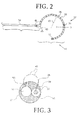
- FIG. 5 is a fragmentary elevational view of a shaft 67 of a catheter that is constructed and operative in accordance with an alternate embodiment of the invention. Electrodes 69 are elliptical in contour. The longitudinal axis 71 of the shaft 67 is aligned with the major axes of the elliptical electrodes. As in the previous embodiment, the surface distribution of perforations 49 is substantially uniform.
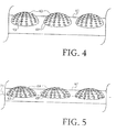
- FIG. 6 is a fragmentary elevational view of a shaft 73 of a catheter that is constructed and operative in accordance with an alternate embodiment of the invention. Electrodes 75 are elliptical in contour. The longitudinal axis 71 of the shaft 73 is aligned with the minor axes of the elliptical electrodes. As in the previous embodiments, the surface distribution of perforations 49 is substantially uniform.
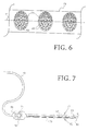
- Fig. 7 is a schematic view of a cardiac catheter 77 in accordance with an alternate embodiment of the invention.
- the catheter 77 includes a flexible body 79.
- An electrode 81 is at a distal portion 83 disposed for measuring the electrical properties of the heart tissue or for ablating defective cardiac tissue.
- the distal portion 83 further includes an array of non-contact electrodes 85 for measuring far field electrical signals in the heart chamber.
- the electrodes 85 may be constructed in accordance with any of the preceding embodiments. The details are not repeated in the interest of brevity.
- An array 87 is a linear array in that the non-contact electrodes 38 are linearly arranged along the longitudinal axis of the distal portion 83.
- the distal portion 83 further includes at least one position sensor 89 that generates signals used to determine the position and orientation of the distal tip 91 within the body.
- the position sensor 89 is preferably adjacent to the tip 91. There is a fixed positional and orientational relationship of the position sensor 89, the tip 91 and the electrode 81.
- a handle 93 of the catheter 14 includes controls 95 to steer or deflect the distal portion 83, or to orient it as desired.
- a cable 97 comprises a receptacle 99, which connects to the handle 93.
- the cable 97 may one or more isolation transformers (not shown), which electrically isolate the catheter 77 from the console 24 ( Fig. 1 ). Alternatively, the isolation transformers may be contained in the receptacle 99 or in the system electronics of the console 24.
- Electrodes 85 may be aligned as a single linear array along the shaft of the distal portion 83 as shown in Fig. 7 .
- Fig. 8 is a fragmentary elevational view of a shaft 103 of a catheter that is constructed and operative in accordance with an alternate embodiment of the invention.
- the electrodes 85 may be disposed as one or more arrays that spiral about the having circumferentially aligned or staggered electrodes that are distributed about the circumference of the shaft 103, and may forming a plurality of linear arrays.
- electrodes 105, 107 form a portion of a first linear array along broken line 109.
- Electrodes 111, 113 form a portion of a second linear array along broken line 115.
- Fig. 9 is a fragmentary elevational view of the shaft or loop segment 41 of the catheter 37 in an unfurled configuration and depicted along a longitudinal axis for illustration purposes in accordance with an alternate embodiment of the present invention.
- loop section 41 has a plurality of circumferential ring ("rings" are “circumferential” by definition) bump electrodes 36A - 36J extending circumferentially 360° around outersurface or loop lumen 47 of the lasso catheter 37, 77 ( Fig. 2 and Fig. 7 ) as best depicted in Fig. 10 .
- loop section 41 has ten (10) separate circumferential ring bump electrodes 36A - 36J extending circumferentially 360° around the entire outer surface or loop lumen 47.
- each circumferential ring bump electrode 36 (depicted collectively as 36A-36J in Fig. 9 ) is made of 90% platinum, 10% iridium by weight in a preferred embodiment and 80% palladium, 20% platinum by weight in an alternative embodiment.
- Each circumferential ring bump electrode 36 has a plurality of perforations 49 made in the material of each ring 36 wherein each perforation 49 is in fluid communication with cavity or chamber 38 circumferentially surrounding the outer surface or loop lumen 47.
- each perforation 49 is in fluid communication with cavity or chamber 38 circumferentially surrounding the outer surface or loop lumen 47.
- each ring electrode 36 is in fluid communication with a channel or breach hole 53 in order for fluid like saline solution to be channeled through irrigating lumen 51 into breach hole 53 which feeds fluid directly into chamber 38 of the bump ring electrode 36 and ultimately dispensed through the bump ring electrode 36 through the perforations 49 dispersed or arranged circumferentially around the ring electrode 36, i.e. the saline can leave from the breach hole 53 and circulate around the chamber 38 and then leave the catheter 37, 77 via the perforations 49 in the ring 36.
- one or more breach holes 53 are used for each ring electrode 36.
- the loop segment 41 of the catheter 37, 77 has a breach hole pattern (53A-53J) ranging proximally to distally along the segment 41 from approximately .005" to .375" in OD (outer diameter). More preferably, breach hole pattern (53A-53J) ranges proximally to distally along the segment 41 from approximately .012" OD to .025" OD.
- breach hole 53A in circumferential ring bump electrode 36A is approximately .0120" OD
- breach hole 53 B in circumferential ring bump electrode 36B is approximately .0128" OD
- breach hole 53C in circumferential ring bump electrode 36C is approximately .0136" OD
- breach hole 53 D in circumferential ring bump electrode 36D is approximately .0142" OD
- breach hole 53E in circumferential ring bump electrode 36E is approximately .0154” OD
- breach hole 53 F in circumferential ring bump electrode 36F is approximately .0174 OD
- breach hole 53G in circumferential ring bump electrode 36G is approximately .0192" OD
- breach hole 53H in circumferential ring bump electrode 36H is approximately .0214” OD
- breach hole 53I in circumferential ring bump electrode 36I is approximately .0236” OD
- breach hole 53J in circumferential ring bump electrode 36J is approximately .0250" OD (all breach holes 53A
- this pattern has the OD for each breach hole 53A-53J of each ring 36A-36J ranging from smaller to larger size in diameter from proximal to distal along the length of the loop segment 41.
- This pattern was experimentally proven to give a relatively balanced flow out of each ring 36 when the pump (not shown) of system 10 ( Fig. 1 ) is operated at the 60ml/min. range.
- the breach hole pattern (53A-53J) shown in Fig. 9 is just one example according to the present invention as the pattern (53A-53J) can be biased further to provide preferential flow to the distal rings, for example rings 36F-36J).
- breach holes 53 are precisely drilled through the outer surface or loop lumen 47 through to the irrigation lumen 51 of the loop lumen 47 and through to the cavity/chamber 38 created by the bump of the circumferential ring electrode 36.
- the change in size of the breach holes 53A-53J under or beneath each ring 36A-36J in general, larger size breach holes 53 ranging proximal to distal) in order to control how much flow each ring 36A - 36J will receive and ultimately dispense through its respective perforations 49.
- breach holes 53A - 53J can be adjusted to balance the flow (as shown in Fig. 9 and described above) in any desired manner or to bias the flow proximally for those applications that require greater fluid volume near the proximal end of the loop segment 41 if necessary.
- breach holes 53A-53J will be arranged with larger size breach hole OD more proximal and smaller size breach holes more distal, i.e. an opposite arrangement to that shown and described in Fig. 9 .
- the distal section or loop segment 41 has a breach hole pattern (53A-53J) that is customized in any desired manner in order to bias or provide preferential flow of irrigating fluid to one end of loop segment 41 or the opposite end of loop segment 41.
- breach holes at or near the middle portion of loop segment 41 for example breach holes 53D-53J, can have similar sized holes for an even distribution of irrigating flow at the middle portion of the loop segment 41 while the breach holes 53A-53C and 53H-53J can have either larger or smaller sized holes than the centrally located breach holes 53D-53J for those medical applications that require this type of pattern of irrigating fluid.
- a single ring electrode 36 is supplied with irrigating fluid by more than one breach hole 53.
- the shape of the hole 53 can be any desired shape, such as a rectangular shape, elliptical shape, triangular, square, etc. wherein any shape which is other than circular has an area equivalent to areas of the circular holes with OD mentioned previously above.
- the loop segment 41 has position sensor lumen 50 for at least one position sensor 89 ( Fig. 2 ) and a third lumen 52 for a nitinol deflection wire and puller wire (not shown).
- the nitinol wire is allows the catheter 27, 77 to take on its "lasso" or circular shape. Since the wire through lumen 52 is made of nitinol, it is super elastic which allows distal segment 41 to be straightened in order to facilitate movement of distal segment 41 into a guiding catheter sheath and then take its circular shape as it leaves the sheath without permanently bending.
- Distal segment 41 is a variable loop that easily adjusts to fit any size vein, for example, a vein sized between 25 and 15 mm in diameter.
- the puller wire in third lumen 52 is used to contract the diameter of the circular distal segment 41 (lasso) in order to accommodate the diameter of the vein and ensure good contact of the circumferential ring bump electrodes 36 with the inner surface of the vein (or other intended tissue target within the heart chamber).
Abstract
Description
- This invention relates to cardiac mapping and ablation systems. More particularly, this invention relates to a lasso catheter for use in a cardiac mapping and ablation system.
- Cardiac arrhythmia, such as atrial fibrillation, occurs when regions of cardiac tissue abnormally conduct electric signals to adjacent tissue, thereby disrupting the normal cardiac cycle and causing asynchronous rhythm. Important sources of undesired signals are located in the tissue region along the pulmonary veins of the left atrium and in the superior pulmonary veins. In this condition, after unwanted signals are generated in the pulmonary veins or conducted through the pulmonary veins from other sources, they are conducted into the left atrium where they can initiate or continue arrhythmia.
- Procedures for treating arrhythmia include surgically disrupting the origin of the signals causing the arrhythmia, as well as disrupting the conducting pathway for such signals. More recently, it has been found that by mapping the electrical properties of the endocardium and the heart volume, and selectively ablating cardiac tissue by application of energy, it is sometimes possible to cease or modify the propagation of unwanted electrical signals from one portion of the heart to another. The ablation process destroys the unwanted electrical pathways by formation of non-conducting lesions.
- In this two-step procedure--mapping followed by ablation--electrical activity at points in the heart is typically sensed and measured by advancing a catheter containing one or more electrical sensors into the heart, and acquiring data at a multiplicity of points. These data are then utilized to select the target areas at which ablation is to be performed.
-
U.S. Pat. No. 6,063,022 to Ben-Haim , which is assigned to the assignee of the present patent application and is incorporated herein by reference, describes an invasive probe including two position sensors in a fixed, known relation to the distal end of the probe. The position sensors generate signals responsive to their respective position coordinates and at least one contact sensor along a radial surface of the probe for generating a signal representing its contact with body tissue to be ablated by electrodes on the probe. -
U.S. Pat. No. 6,272,371 to Ben-Haim , which is assigned to the assignee of the present patent application and is incorporated herein by reference, describes an invasive probe including a flexible portion that assumes a predetermined curve form when a force is applied thereto. Two position sensors, fixed to the distal portion of the probe in known positions, are used to determine position and orientation coordinates of at least one of the sensors, and to determine the locations of a plurality of points along the length of the distal portion of the probe. -
PCT Patent Publication WO 96/05768 U.S. Patent Application Publication 2002/0065455 to Ben-Haim et al. , which are assigned to the assignee of the present patent application and which are incorporated herein by reference, describe a system that generates six-dimensional position and orientation information regarding the tip of a catheter. This system uses a plurality of sensor coils adjacent to a locatable site in the catheter, for example near its distal end, and a plurality of radiator coils fixed in an external reference frame. These coils generate signals in response to magnetic fields generated by the radiator coils, which signals allow for the computation of six position and orientation dimensions, so that the position and orientation of the catheter are known without the need for imaging the catheter. - A lasso catheter is disclosed in commonly assigned
U.S. Patent No. 6,973,339 , which is herein incorporated by reference. The lasso catheter is particularly adapted for pulmonary vein mapping and ablation. This catheter comprises: a curved section having a first position sensor that is capable of generating fewer than six dimensions of position and orientation information, one or more electrodes, adapted to measure an electrical property of the pulmonary vein; and a base section attached to a proximal end of the curved section. Disposed on the base section within 3 mm of the distal end thereof is a second position sensor, capable of generating six dimensions of position and orientation information. - Lasso catheters are generally used for ablating tissue along an arc surrounding an anatomical structure, such as the ostium of a pulmonary vein. Conventionally, the curved section or loop of the lasso catheter is generally thin and "floppy," for purposes of maneuverability, while ring electrodes disposed on the lasso are relatively large in order to minimize electrical resistance.
- Embodiments of the present invention provide a lasso catheter that may be used for both ablation and sensing, and which has other advantageous features. Its distal curved portion, sometimes referred to herein as a "loop" or "loop segment", is typically thicker and stiffer than that of conventional lasso catheters. Rather than ring electrodes, the lasso catheter has relatively small, raised protuberant electrodes. The small size of these electrodes is advantageous in permitting measurement of local electrical activity with good spatial resolution. The bulges of the electrodes increase the surface area that is in contact with the heart tissue, and thus reduces the electrical resistance when the electrodes are used for ablation.
- In order to provide local cooling and prevent adhesion during ablation, the electrodes may be fenestrated by multiple perforations. The perforations are in fluid contact with a lumen, which carries irrigation fluid from within the catheter to the outer surfaces of the electrodes and thence to the adjacent tissues. Another lumen may contain wires connected to each of the electrodes.
- An embodiment of the invention provides a catheter, including an insertion tube and a resilient distal section fixed to the distal end of the insertion tube. The distal section has an inner irrigating lumen and a plurality of electrodes that bulge above the outer surface. The electrodes have a plurality of perforations formed there-through, and the outer surface is in fluid communication with the irrigating lumen via the perforations.
- According to an aspect of the catheter, the insertion tube is configured for insertion through a blood vessel into a heart of a subject, and wherein the resilient distal section defines an open loop when deployed within the heart.
- An embodiment of the invention provides a method for locating an arrhythmogenic area in a heart of a living subject, The method is further carried out by inserting a catheter into a chamber of the heart, the catheter including an insertion tube and a resilient distal section that has an inner irrigating lumen and is fixed to the distal end of the insertion tube. The distal section also includes a plurality of electrodes that bulge above the outer surface, the electrodes having a plurality of perforations formed there-through. The outer surface of the distal section is in fluid communication with the irrigating lumen via the perforations, The method is further carried out by locating the catheter in proximity to a target in the chamber, analyzing electrical signals received from the target via the catheter to make a determination that the electrical signals are indicative of abnormal electrical conduction within the heart, and responsively to the determination, conducting energy into the heart to thereby affect the abnormal electrical conduction.
- According to another preferred embodiment, the present invention is a catheter comprising an insertion tube having a distal end and a resilient distal section fixed to the distal end of the insertion tube. The distal section can also be in the form of a "loop" or "loop segment". The distal section has an outer surface and an inner irrigating lumen and comprises a plurality of ring electrodes that bulge above the outer surface and are circumferentially arranged around the entire circumference of the outer surface. Each ring electrode defines a cavity thereunder. The ring electrodes have a plurality of perforations formed there-through and the outer surface has a breach hole (or holes) therein positioned beneath each ring electrode and in fluid communication with the irrigating lumen. The cavity and the perforations of each ring electrode facilitate dispensing of irrigating fluid from the distal section through each ring electrode.
- According to the present invention, the diameter of the breach hole for each ring electrode varies in size. For example, in one embodiment, the diameter of the breach hole for each ring electrode varies in size from smaller to larger from proximal to distal along the resilient distal section. Alternatively, in another embodiment according o the present invention, the diameter of the breach hole for each ring electrode varies in size from larger to smaller from proximal to distal along the resilient distal section.
- Breach hole (or holes) could be of circular or other shape (for example: rectangular).
- For a better understanding of the present invention, reference is made to the detailed description of the invention, by way of example, which is to be read in conjunction with the following drawings, wherein like elements are given like reference numerals, and wherein:
-
Fig. 1 is a pictorial illustration of a system for detecting areas of abnormal electrical activity and performing ablative procedures on a heart of a living subject in accordance with a disclosed embodiment of the invention; -
Fig. 2 is a side elevation of a lasso catheter that is constructed and operative in accordance with a disclosed embodiment of the invention; -
Fig. 3 is a cross section through the catheter shown inFig. 2 taken through line 3-3; -
Fig. 4 a fragmentary elevational view of the shaft of a catheter that is constructed and operative in accordance with a disclosed embodiment of the invention; -
Fig. 5 is a fragmentary elevational view of the shaft of a catheter that is constructed and operative in accordance with an alternate embodiment of the invention; -
Fig. 6 is a fragmentary elevational view of the shaft of a catheter that is constructed and operative in accordance with an alternate embodiment of the invention; -
Fig. 7 is a schematic view of a cardiac catheter in accordance with an alternate embodiment of the invention; -
Fig. 8 is a fragmentary elevational view of a shaft of a catheter having a plurality of linear electrode arrays that is constructed and operative in accordance with an alternate embodiment of the invention; -
Fig. 9 is a fragmentary elevational view of the shaft of a catheter that is constructed and operative in accordance with an alternate embodiment of the invention; -
Fig. 10 is a cross section through the catheter shown inFig. 9 taken through a circumferential ring bump electrode in accordance with the invention; and -
Fig. 11 is a side elevation view in longitudinal cross section through a circumferential ring bump electrode of the catheter shown inFig. 9 in accordance with the invention. - In the following description, numerous specific details are set forth in order to provide a thorough understanding of the various principles of the present invention. It will be apparent to one skilled in the art, however, that not all these details are necessarily always needed for practicing the present invention. In this instance, well-known circuits, control logic, and the details of computer program instructions for conventional algorithms and processes have not been shown in detail in order not to obscure the general concepts unnecessarily.
- Turning now to the drawings, reference is initially made to
Fig. 1 , which is a pictorial illustration of asystem 10 for detecting areas of abnormal electrical activity and performing ablative procedures on aheart 12 of a living subject in accordance with a disclosed embodiment of the invention. The system comprises alasso catheter 14, which is percutaneously inserted by anoperator 16, who is typically a physician, through the patient's vascular system into a chamber or vascular structure of the heart. Theoperator 16 brings the catheter's distal tip 18 ("18" has to be moved closer to the loop-the way it is looks that indicates a heart chamber rather than the distal tip (loop) of the catheter) into contact with the heart wall at a target site that is to be evaluated. Electrical activation maps are then prepared, according to the methods disclosed in the above-notedU.S. Patent Nos. 6,226,542 , and6,301,496 , and in commonly assignedU.S. Patent No. 6,892,091 , whose disclosure is herein incorporated by reference. - Areas determined to be abnormal by evaluation of the electrical activation maps can be ablated by application of electrical energy, e.g., by passage of radiofrequency electrical current through wires in the catheter to one or more electrodes at the
distal tip 18, which apply the radiofrequency energy to the myocardium. The energy is absorbed in the tissue, heating it to a point (typically about 50°C) at which it permanently loses its electrical excitability. When successful, this procedure creates non-conducting lesions in the cardiac tissue, which disrupt the abnormal electrical pathway causing the arrhythmia. Alternatively, other known methods of applying ablative energy can be used, e.g., ultrasound energy, as disclosed inU.S. Patent Application Publication No. 2004/0102769 , whose disclosure is herein incorporated by reference. The principles of the invention can be applied to different heart chambers, and to mapping in sinus rhythm, and when many different cardiac arrhythmias are present. - The
catheter 14 typically comprises ahandle 20, having suitable controls on the handle to enable theoperator 16 to steer, position and orient the distal end of the catheter as desired for the ablation. To aid theoperator 16, the distal portion of thecatheter 14 contains position sensors (not shown) that provide signals to apositioning processor 22, located in aconsole 24. Theconsole 24 typically contains anablation power generator 25. Thecatheter 14 may be adapted to conduct ablative energy to the heart using any known ablation technique, e.g., radiofrequency energy, ultrasound energy, and laser energy. Such methods are disclosed in commonly assignedU.S. Patent Nos. 6,814,733 ,6,997,924 , and7,156,816 , which are herein incorporated by reference. - The
positioning processor 22 is an element of apositioning system 26 that measures location and orientation coordinates of thecatheter 14. Throughout this patent application, the term "location" refers to the spatial coordinates of the catheter, and the term "orientation" refers to its angular coordinates. The term "position" refers to the full positional information of the catheter, comprising both location and orientation coordinates. - In one embodiment, the
positioning system 26 comprises a magnetic position tracking system that determines the position and orientation of thecatheter 14. Thepositioning system 26 generates magnetic fields in a predefined working volume its vicinity and senses these fields at the catheter. Thepositioning system 26 typically comprises a set of external radiators, such as field generating coils 28, which are located in fixed, known positions external to the patient. Thecoils 28 generate fields, typically electromagnetic fields, in the vicinity of theheart 12. - In an alternative embodiment, a radiator in the
catheter 14, such as a coil, generates electromagnetic fields, which are received by sensors (not shown) outside the patient's body. - Some position tracking systems that may be used for this purpose are described, for example, in the above-noted
U.S. Patents 6,690,963 , and in commonly assignedU.S. Patent Nos. 6,618,612 and6,332,089 , andU.S. Patent Application Publications 2004/0147920 , and2004/0068178 , whose disclosures are all incorporated herein by reference. Although thepositioning system 26 shown inFig. 1 uses magnetic fields, the methods described below may be implemented using any other suitable positioning system, such as systems based on electromagnetic fields, acoustic or ultrasonic measurements. Thepositioning system 26 may be realized as the CARTO XP EP Navigation and Ablation System, available from Biosense Webster, Inc., 3333 Diamond Canyon Road, Diamond Bar, CA 91765. - As noted above, the
catheter 14 is coupled to theconsole 24, which enables theoperator 16 to observe and regulate the functions of thecatheter 14.Console 24 includes a processor, preferably a computer with appropriate signal processing circuits. The processor is coupled to drive amonitor 29. The signal processing circuits typically receive, amplify, filter and digitize signals from thecatheter 14, including signals generated by thesensors sensing electrodes 35. The digitized signals are received and used by theconsole 24 to compute the position and orientation of thecatheter 14 and to analyze the electrical signals from the electrodes. The information derived from this analysis is used to generate an electrophysiological map of at least a portion of theheart 12 or structures such as the pulmonary venous ostia, for diagnostic purposes such as locating an arrhythmogenic area in the heart or to facilitate therapeutic ablation. - Typically, the
system 10 includes other elements, which are not shown in the figures for the sake of simplicity. For example, thesystem 10 may include an electrocardiogram (ECG) monitor, coupled to receive signals from one or more body surface electrodes, so as to provide an ECG synchronization signal to theconsole 24. As mentioned above, thesystem 10 typically also includes a reference position sensor, either on an externally-applied reference patch attached to the exterior of the subject's body, or on an internally-placed catheter, which is inserted into theheart 12 maintained in a fixed position relative to theheart 12. By comparing the position of thecatheter 14 to that of the reference catheter, the coordinates ofcatheter 14 are accurately determined relative to theheart 12, irrespective of heart motion. Alternatively, any other suitable method may be used to compensate for heart motion. - Reference is now made to
Fig. 2 , which is a side elevation of alasso catheter 37 that is constructed and operative in accordance with a disclosed embodiment of the invention. Thecatheter 37 is a steerable device. Its handle, control and steering mechanisms (not shown) are conventional and are omitted fromFig. 2 for simplicity. Thecatheter 37 features abase segment 39, which is bendable responsively to forces applied by the steering mechanisms. A distal curved section, referred to herein asloop segment 41, completes the lasso configuration. Theloop segment 41 is joined to thebase segment 39 by a range-restricted angle α at a joint 43. The angle α between theloop segment 41 and thebase segment 39 optimally is about 90 decrees. The joint 43 may define a point where two initially-separate members (base segment 39; loop segment 41) are joined, or, alternatively, the joint 43 may define a point on thecatheter 37 where a single member is bent, so as to form thebase segment 39 and theloop segment 41. Theloop segment 41 is of a known fixed length, having a curvature dimensioned to a particular medical application. The curvature may be adjustable using the steering and control mechanisms (not shown) of the catheter. Aradius 45 of adjustable between 7 - 15 mm is suitable for cardiac applications. However, theradius 45 may vary up to 25 mm in some applications. In any case, theloop segment 41 may be dimensioned so as to conform to structures such as the ostia of pulmonary veins or the coronary sinus. - The
loop segment 41 is constructed of a material that preferably is twistable but not stretchable when subjected to typical forces encountered in medical practice. Preferably, theloop segment 41 is sufficiently resilient so as to assume a predetermined curved form, i.e., an open circular or semicircular form when no force is applied thereto, and to be deflected from the predetermined curved form when a force is applied thereto. Preferably, theloop segment 41 has an elasticity that is generally constant over at least a portion of its length, for example, because of internal reinforcement of the curved section with a resilient longitudinal member, as is known in the art. Theloop segment 41 is generally thicker and stiffer than conventional lassos. For example, theloop segment 41 may be made from polyurethane and be at least one mm in diameter. - One or
more electrodes 35, adapted for sensing electrical characteristics of cardiac tissue, are fixed to theloop segment 41. Reference is now made toFig. 3 , which is a cross section through the catheter 37 (Fig. 2 ) taken through line 3-3, illustrating one of theelectrodes 35. Theelectrodes 35 may bulge between about 0.1-0.5 mm above theouter surface 47 and have a generally rounded profile, forming a cap on thesurface 47. In some embodiments theelectrodes 35 may have a larger bulge, up to 1 mm above the surface. Theelectrodes 35 may extend over 25-270 per cent of the circumference of thesurface 47, as contrasted with a conventional ring electrode, which covers 100% of the circumference. Theelectrodes 35 may have a circular border. Alternatively, they may be elliptical in contour, as further described below. These configurations provide substantial contact between theelectrodes 35 and the cardiac tissue, lowering electrical resistance as compared with conventional electrodes. Theelectrodes 35 may be 2-5 mm in dimension. Theelectrodes 35 may also be used for ablation, in which case the reduced electrical resistance is particularly advantageous. In one embodiment, two of theelectrodes 35 are selected for performing bi-polar ablation, e.g., radiofrequency ablation in which case acable 57 may include wires individually leading to theelectrodes 35. - The exterior surface of the
electrodes 35 is fenestrated by multiplesmall perforations 49 formed there-through. Typically there are between 1 and 50 perforations having diameters of 0.05-0.4 mm. Perforations could also be any other shape area (not circular), for example rectangular, wherein these other shaped areas are equivalent to the area of circular perforations of diameter 0.05-0.4 mm. Theperforations 49 are in fluid communication with anirrigating lumen 51 through achannel 53. Asecond lumen 55 carriescable 57 comprising one or more electrically conductive wires that link theelectrodes 35 to the console 24 (Fig. 1 ), forexample wire 59. Thelumen 55 may also conduct additional wires as described below. - Reference is now made to
Fig. 4 , which is a fragmentary elevational view of ashaft 61 of a catheter that is constructed and operative in accordance with a disclosed embodiment of the invention. Electrodes 63 are circular in contour, and the surface distribution ofperforations 49 is substantially uniform. - Reverting to
Fig. 2 , at least a first single-coil position sensor 31 is fixed toloop segment 41. Preferably, thesensor 31 is fixed to the distal end of the loop segment 41 (distal with respect to the base segment 39), and a second single-coil position sensor 33 is fixed to the approximate center of theloop segment 41. Optionally, one or more additional single-coil position sensors (not shown) are fixed to theloop segment 41. Additionally, amulti-coil position sensor 65 is preferably fixed near the distal end of thebase segment 39, in the vicinity of the joint 43, typically within 10 mm of the distal end. Thesensor 65 is preferably able to generate six position and orientation dimensions, using techniques described in the above-cited PCT Patent Publications to Ben-Haim et al., or other techniques known in the art. Thesensor 65 preferably comprises two or three coils, which are generally sufficient for generating six dimensions of position information. Thesensors sensors sensors sensor 65. - The
sensors catheter 37 by any suitable method, for example, using polyurethane glue or the like. Thesensors Fig. 3 ), which extends through the catheter body and into a control handle (not shown) of thecatheter 37. Thecable 57 preferably comprises multiple wires encased within a plastic covered sheath. Within the catheter body, thecable 57 may be enclosed within a protective sheath along with wire 59 (Fig. 3 ). Preferably, in the control handle, the wires of the sensor cable are connected to a circuit board (not shown), which amplifies the signals received from the position sensors and transmits them to a computer housed in the console 24 (Fig. 1 ), in a form understandable to the computer. Alternatively, amplifying circuitry is included at the distal end ofcatheter 37, so as to reduce the effect of noise. - Reference is again made to
Fig. 1 . In order to use theposition sensors catheter 37 is advanced into the subject's heart and into a desired location in or near one of the cardiac chambers, for example one of the pulmonary veins. Reverting now toFig. 2 , the coils in thesensors sensors Fig. 1 ), which analyzes the signals so as to facilitate the determination and visual display of the precise location of thesensors - Each of the
sensors sensor 65 preferably comprises three non-concentric, typically mutually orthogonal coils, such as those described in the above-citedPCT Patent Publication WO 96/05768 coils 28, which are driven by driver circuits in the generator 25 (Fig. 1 ). Alternatively, the sensors may generate fields, which are detected by fixed sensing coils (not shown), in which case thecoils 28 can be omitted. Thesystem 10 thus achieves continuous generation of five dimensions of position and orientation information with respect to each of thesensors sensor 65. - Reference is now made to
Fig. 5 , which is a fragmentary elevational view of a shaft 67 of a catheter that is constructed and operative in accordance with an alternate embodiment of the invention.Electrodes 69 are elliptical in contour. Thelongitudinal axis 71 of the shaft 67 is aligned with the major axes of the elliptical electrodes. As in the previous embodiment, the surface distribution ofperforations 49 is substantially uniform. - Reference is now made to
Fig. 6 , which is a fragmentary elevational view of ashaft 73 of a catheter that is constructed and operative in accordance with an alternate embodiment of the invention.Electrodes 75 are elliptical in contour. Thelongitudinal axis 71 of theshaft 73 is aligned with the minor axes of the elliptical electrodes. As in the previous embodiments, the surface distribution ofperforations 49 is substantially uniform. - The irrigated bump electrodes shown in the figure may also be arrayed along the length of catheters or probes of other types than lasso catheters. Reference is now made to
Fig. 7 , which is a schematic view of acardiac catheter 77 in accordance with an alternate embodiment of the invention. - The
catheter 77 includes aflexible body 79. Anelectrode 81 is at adistal portion 83 disposed for measuring the electrical properties of the heart tissue or for ablating defective cardiac tissue. Thedistal portion 83 further includes an array ofnon-contact electrodes 85 for measuring far field electrical signals in the heart chamber. Theelectrodes 85 may be constructed in accordance with any of the preceding embodiments. The details are not repeated in the interest of brevity. - An array 87 is a linear array in that the
non-contact electrodes 38 are linearly arranged along the longitudinal axis of thedistal portion 83. Thedistal portion 83 further includes at least oneposition sensor 89 that generates signals used to determine the position and orientation of thedistal tip 91 within the body. Theposition sensor 89 is preferably adjacent to thetip 91. There is a fixed positional and orientational relationship of theposition sensor 89, thetip 91 and theelectrode 81. - A
handle 93 of thecatheter 14 includescontrols 95 to steer or deflect thedistal portion 83, or to orient it as desired. Acable 97 comprises areceptacle 99, which connects to thehandle 93. Thecable 97 may one or more isolation transformers (not shown), which electrically isolate thecatheter 77 from the console 24 (Fig. 1 ). Alternatively, the isolation transformers may be contained in thereceptacle 99 or in the system electronics of theconsole 24. - In embodiments in which there are three or
more electrodes 85, they may be aligned as a single linear array along the shaft of thedistal portion 83 as shown inFig. 7 . - Reference is now made to
Fig. 8 , which is a fragmentary elevational view of ashaft 103 of a catheter that is constructed and operative in accordance with an alternate embodiment of the invention. Alternatively, theelectrodes 85 may be disposed as one or more arrays that spiral about the having circumferentially aligned or staggered electrodes that are distributed about the circumference of theshaft 103, and may forming a plurality of linear arrays. For example, as shown inFig. 8 ,electrodes broken line 109.Electrodes broken line 115. -
Fig. 9 is a fragmentary elevational view of the shaft orloop segment 41 of thecatheter 37 in an unfurled configuration and depicted along a longitudinal axis for illustration purposes in accordance with an alternate embodiment of the present invention. As shown inFig. 9 ,loop section 41 has a plurality of circumferential ring ("rings" are "circumferential" by definition)bump electrodes 36A - 36J extending circumferentially 360° around outersurface orloop lumen 47 of thelasso catheter 37, 77 (Fig. 2 andFig. 7 ) as best depicted inFig. 10 . - In this embodiment,
loop section 41 has ten (10) separate circumferentialring bump electrodes 36A - 36J extending circumferentially 360° around the entire outer surface orloop lumen 47. - As best shown in
Fig. 10 andFig. 11 , each circumferential ring bump electrode 36 (depicted collectively as 36A-36J inFig. 9 ) is made of 90% platinum, 10% iridium by weight in a preferred embodiment and 80% palladium, 20% platinum by weight in an alternative embodiment. - Each circumferential
ring bump electrode 36 has a plurality ofperforations 49 made in the material of eachring 36 wherein eachperforation 49 is in fluid communication with cavity orchamber 38 circumferentially surrounding the outer surface orloop lumen 47. Preferably, there are anywhere between 2 and 25separate perforations 49 in eachring 36 and more preferably ten (10)distinct perforations 49 circumferentially arranged throughout eachring 36. - The cavity or
chamber 38 in eachring electrode 36 is in fluid communication with a channel orbreach hole 53 in order for fluid like saline solution to be channeled through irrigatinglumen 51 intobreach hole 53 which feeds fluid directly intochamber 38 of thebump ring electrode 36 and ultimately dispensed through thebump ring electrode 36 through theperforations 49 dispersed or arranged circumferentially around thering electrode 36, i.e. the saline can leave from thebreach hole 53 and circulate around thechamber 38 and then leave thecatheter perforations 49 in thering 36. Preferably, one or more breach holes 53 are used for eachring electrode 36. - As best depicted in
Fig. 9 , theloop segment 41 of thecatheter segment 41 from approximately .005" to .375" in OD (outer diameter). More preferably, breach hole pattern (53A-53J) ranges proximally to distally along thesegment 41 from approximately .012" OD to .025" OD. - For example,
breach hole 53A in circumferentialring bump electrode 36A is approximately .0120" OD,breach hole 53 B in circumferentialring bump electrode 36B is approximately .0128" OD, breach hole 53C in circumferentialring bump electrode 36C is approximately .0136" OD,breach hole 53 D in circumferentialring bump electrode 36D is approximately .0142" OD,breach hole 53E in circumferentialring bump electrode 36E is approximately .0154" OD,breach hole 53 F in circumferentialring bump electrode 36F is approximately .0174 OD,breach hole 53G in circumferentialring bump electrode 36G is approximately .0192" OD,breach hole 53H in circumferentialring bump electrode 36H is approximately .0214" OD, breach hole 53I in circumferential ring bump electrode 36I is approximately .0236" OD andbreach hole 53J in circumferentialring bump electrode 36J is approximately .0250" OD (allbreach holes 53A - 53J with OD tolerance or variance +/- .0005"). - As shown in
Fig. 9 and described, this pattern has the OD for eachbreach hole 53A-53J of eachring 36A-36J ranging from smaller to larger size in diameter from proximal to distal along the length of theloop segment 41. This pattern was experimentally proven to give a relatively balanced flow out of eachring 36 when the pump (not shown) of system 10 (Fig. 1 ) is operated at the 60ml/min. range. The breach hole pattern (53A-53J) shown inFig. 9 is just one example according to the present invention as the pattern (53A-53J) can be biased further to provide preferential flow to the distal rings, for example rings 36F-36J). - As best shown in
Fig. 10 andFig. 11 , breach holes 53 are precisely drilled through the outer surface orloop lumen 47 through to theirrigation lumen 51 of theloop lumen 47 and through to the cavity/chamber 38 created by the bump of thecircumferential ring electrode 36. The change in size of the breach holes 53A-53J under or beneath eachring 36A-36J (in general, larger size breach holes 53 ranging proximal to distal) in order to control how much flow eachring 36A - 36J will receive and ultimately dispense through itsrespective perforations 49. - Thus, it is important to note that the adjusting of the size of
breach holes 53A-53J in the manner prescribed by the present invention eliminates the need to adjust theperforations 49 on the rings themselves, thereby allowing the catheter to be built with all the same ring components. This is more cost effective and efficient for manufacturing and pricing. - It is also important to note that the breach holes 53A - 53J can be adjusted to balance the flow (as shown in
Fig. 9 and described above) in any desired manner or to bias the flow proximally for those applications that require greater fluid volume near the proximal end of theloop segment 41 if necessary. Thus, breach holes 53A-53J will be arranged with larger size breach hole OD more proximal and smaller size breach holes more distal, i.e. an opposite arrangement to that shown and described inFig. 9 . - Accordingly, the distal section or
loop segment 41 has a breach hole pattern (53A-53J) that is customized in any desired manner in order to bias or provide preferential flow of irrigating fluid to one end ofloop segment 41 or the opposite end ofloop segment 41. Moreover, in accordance with the present invention, breach holes at or near the middle portion ofloop segment 41, forexample breach holes 53D-53J, can have similar sized holes for an even distribution of irrigating flow at the middle portion of theloop segment 41 while the breach holes 53A-53C and 53H-53J can have either larger or smaller sized holes than the centrally locatedbreach holes 53D-53J for those medical applications that require this type of pattern of irrigating fluid. - Alternatively, a
single ring electrode 36 is supplied with irrigating fluid by more than onebreach hole 53. The shape of thehole 53 can be any desired shape, such as a rectangular shape, elliptical shape, triangular, square, etc. wherein any shape which is other than circular has an area equivalent to areas of the circular holes with OD mentioned previously above. - In accordance with a preferred embodiment, as shown in
Fig. 10 , theloop segment 41 hasposition sensor lumen 50 for at least one position sensor 89 (Fig. 2 ) and athird lumen 52 for a nitinol deflection wire and puller wire (not shown). The nitinol wire is allows thecatheter 27, 77 to take on its "lasso" or circular shape. Since the wire throughlumen 52 is made of nitinol, it is super elastic which allowsdistal segment 41 to be straightened in order to facilitate movement ofdistal segment 41 into a guiding catheter sheath and then take its circular shape as it leaves the sheath without permanently bending.Distal segment 41 is a variable loop that easily adjusts to fit any size vein, for example, a vein sized between 25 and 15 mm in diameter. The puller wire inthird lumen 52 is used to contract the diameter of the circular distal segment 41 (lasso) in order to accommodate the diameter of the vein and ensure good contact of the circumferentialring bump electrodes 36 with the inner surface of the vein (or other intended tissue target within the heart chamber). - It will be appreciated by persons skilled in the art that the present invention is not limited to what has been particularly shown and described hereinabove. Rather, the scope of the present invention includes both combinations and sub-combinations of the various features described hereinabove, as well as variations and modifications thereof that are not in the prior art, which would occur to persons skilled in the art upon reading the foregoing description.
Claims (12)
- A catheter, comprising:an insertion tube having a distal end; anda resilient distal section fixed to the distal end of the insertion tube, the distal section having an outer surface and an inner irrigating lumen and comprises a plurality of ring electrodes that bulge above the outer surface and are circumferentially arranged around the entire circumference of the outer surface, each ring electrode defining a cavity thereunder, the ring electrodes having a plurality of perforations formed therethrough, the outer surface having at least one breach hole therein positioned beneath each ring electrode and in fluid communication with the irrigating lumen, the cavity and the perforations of each ring electrode for dispensing irrigating fluid from the resilient distal section through each ring electrode.
- The catheter according to claim 1, wherein the insertion tube is configured for insertion through a blood vessel into a heart of a subject, and wherein the resilient distal section defines an open loop when deployed within the heart.
- The catheter according to claim 2, wherein the diameter of the at least one breach hole for each ring electrode varies in size.
- The catheter according to claim 3, wherein the diameter of the at least one breach hole for each ring electrode varies in size from smaller to larger from proximal to distal along the resilient distal section.
- The catheter according to claim 3, wherein the diameter of the at least one breach hole for each ring electrode varies in size from larger to smaller from proximal to distal along the resilient distal section.
- The catheter according to claim 1, wherein the diameter of the at least one breach hole for each ring electrode in a middle portion of the distal section are similar in size and the diameter for each breach hole proximal and distal of the middle portion are different in size from each breach hole of the middle portion of the resilient distal section.
- The catheter according to any one of claims 4 to 6, wherein the resilient distal section has at least three ring electrodes.
- The catheter according to claim 7, wherein the resilient distal section has ten ring electrodes.
- The catheter according to claim 4 or claim 8, wherein the distal segment has a breach hole pattern ranging proximally to distally along the segment from approximately .005" to .375" in OD (outer diameter).
- The catheter according to claim 9, wherein the distal segment has a breach hole pattern ranging proximally to distally along the segment from approximately .012" to .025" OD (outer diameter).
- The catheter according to claim 1 or claim 10 when dependent on claims 9 and 8, wherein the ring electrodes are made of 90% platinum, 10% iridium by weight.
- The catheter according to claim 1 or claim 10 when dependent on claims 9 and 8, wherein the ring electrodes are made of 80% palladium, 20% platinum by weight.
Applications Claiming Priority (1)
| Application Number | Priority Date | Filing Date | Title |
|---|---|---|---|
| US12/764,561 US8600472B2 (en) | 2008-12-30 | 2010-04-21 | Dual-purpose lasso catheter with irrigation using circumferentially arranged ring bump electrodes |
Publications (3)
| Publication Number | Publication Date |
|---|---|
| EP2380518A2 true EP2380518A2 (en) | 2011-10-26 |
| EP2380518A3 EP2380518A3 (en) | 2013-02-06 |
| EP2380518B1 EP2380518B1 (en) | 2020-10-21 |
Family
ID=44262645
Family Applications (1)
| Application Number | Title | Priority Date | Filing Date |
|---|---|---|---|
| EP11163281.6A Active EP2380518B1 (en) | 2010-04-21 | 2011-04-20 | Dual-purpose lasso catheter with irrigation using circumferentially arranged ring bump electrodes |
Country Status (7)
| Country | Link |
|---|---|
| US (1) | US8600472B2 (en) |
| EP (1) | EP2380518B1 (en) |
| JP (1) | JP5788205B2 (en) |
| CN (1) | CN102274021B (en) |
| AU (1) | AU2011201663B2 (en) |
| CA (1) | CA2737678C (en) |
| IL (1) | IL212307A (en) |
Cited By (6)
| Publication number | Priority date | Publication date | Assignee | Title |
|---|---|---|---|---|
| EP2644223A1 (en) | 2012-03-26 | 2013-10-02 | Biosense Webster (Israel), Ltd. | Catheter with composite construction |
| EP2664295A1 (en) * | 2012-05-14 | 2013-11-20 | Biosense Webster (Israel), Ltd. | Catheter with helical end section for vessel ablation |
| US9220433B2 (en) | 2011-06-30 | 2015-12-29 | Biosense Webster (Israel), Ltd. | Catheter with variable arcuate distal section |
| US9662169B2 (en) | 2011-07-30 | 2017-05-30 | Biosense Webster (Israel) Ltd. | Catheter with flow balancing valve |
| US10639099B2 (en) | 2012-05-25 | 2020-05-05 | Biosense Webster (Israel), Ltd. | Catheter having a distal section with spring sections for biased deflection |
| US11471650B2 (en) | 2019-09-20 | 2022-10-18 | Biosense Webster (Israel) Ltd. | Mechanism for manipulating a puller wire |
Families Citing this family (54)
| Publication number | Priority date | Publication date | Assignee | Title |
|---|---|---|---|---|
| US8475450B2 (en) | 2008-12-30 | 2013-07-02 | Biosense Webster, Inc. | Dual-purpose lasso catheter with irrigation |
| US8926605B2 (en) | 2012-02-07 | 2015-01-06 | Advanced Cardiac Therapeutics, Inc. | Systems and methods for radiometrically measuring temperature during tissue ablation |
| US9277961B2 (en) | 2009-06-12 | 2016-03-08 | Advanced Cardiac Therapeutics, Inc. | Systems and methods of radiometrically determining a hot-spot temperature of tissue being treated |
| US8954161B2 (en) | 2012-06-01 | 2015-02-10 | Advanced Cardiac Therapeutics, Inc. | Systems and methods for radiometrically measuring temperature and detecting tissue contact prior to and during tissue ablation |
| US9226791B2 (en) | 2012-03-12 | 2016-01-05 | Advanced Cardiac Therapeutics, Inc. | Systems for temperature-controlled ablation using radiometric feedback |
| US8920415B2 (en) | 2009-12-16 | 2014-12-30 | Biosense Webster (Israel) Ltd. | Catheter with helical electrode |
| US8608735B2 (en) | 2009-12-30 | 2013-12-17 | Biosense Webster (Israel) Ltd. | Catheter with arcuate end section |
| JP5670572B2 (en) * | 2010-08-31 | 2015-02-18 | クック メディカル テクノロジーズ エルエルシーCook Medical Technologies Llc | Cautery overtube |
| US10517667B2 (en) * | 2014-05-16 | 2019-12-31 | Biosense Webster (Israel) Ltd. | Catheter tip with microelectrodes |
| US10743932B2 (en) * | 2011-07-28 | 2020-08-18 | Biosense Webster (Israel) Ltd. | Integrated ablation system using catheter with multiple irrigation lumens |
| US8876726B2 (en) | 2011-12-08 | 2014-11-04 | Biosense Webster (Israel) Ltd. | Prevention of incorrect catheter rotation |
| US9050105B2 (en) * | 2012-03-20 | 2015-06-09 | Biosense Webster (Israel) Ltd. | Catheter with multiple irrigated electrodes and a force sensor |
| US9314299B2 (en) * | 2012-03-21 | 2016-04-19 | Biosense Webster (Israel) Ltd. | Flower catheter for mapping and ablating veinous and other tubular locations |
| US9439722B2 (en) * | 2012-05-09 | 2016-09-13 | Biosense Webster (Israel) Ltd. | Ablation targeting nerves in or near the inferior vena cava and/or abdominal aorta for treatment of hypertension |
| US8986300B2 (en) * | 2012-06-25 | 2015-03-24 | Biosense Webster (Israel) Ltd. | Irrigated electrodes with enhanced heat conduction |
| JP6059945B2 (en) * | 2012-10-23 | 2017-01-11 | 株式会社カネカ | Tip loop type electrode sweater |
| CN102908191A (en) * | 2012-11-13 | 2013-02-06 | 陈绍良 | Multipolar synchronous pulmonary artery radiofrequency ablation catheter |
| US11241267B2 (en) | 2012-11-13 | 2022-02-08 | Pulnovo Medical (Wuxi) Co., Ltd | Multi-pole synchronous pulmonary artery radiofrequency ablation catheter |
| US9827036B2 (en) | 2012-11-13 | 2017-11-28 | Pulnovo Medical (Wuxi) Co., Ltd. | Multi-pole synchronous pulmonary artery radiofrequency ablation catheter |
| CN103830001B (en) * | 2012-11-23 | 2016-12-21 | 四川锦江电子科技有限公司 | Controllable bending spiral ablation catheter |
| US9078667B2 (en) * | 2012-12-11 | 2015-07-14 | St. Jude Medical, Atrial Fibrillation Division, Inc. | Catheter having reduced force concentration at tissue contact site |
| CN205215353U (en) | 2013-02-07 | 2016-05-11 | 上海魅丽纬叶医疗科技有限公司 | Radio frequency melts system and radio frequency melts equipment thereof |
| CN103505798B (en) * | 2013-09-30 | 2015-09-09 | 上海魅丽纬叶医疗科技有限公司 | The fluted ablation catheter in surface |
| US20140228801A1 (en) * | 2013-02-12 | 2014-08-14 | Gary Keeling | Body cavity drainage device and methods for using the same |
| US10265025B2 (en) * | 2013-06-25 | 2019-04-23 | Biosense Webster (Israel) Ltd. | Electrocardiogram noise reduction |
| KR101459941B1 (en) * | 2013-08-23 | 2014-11-07 | 고려대학교 산학협력단 | Multi-electrode catheter for mapping and ablating lesion parts |
| CN105286986B (en) * | 2014-07-30 | 2018-07-10 | 上海微创电生理医疗科技股份有限公司 | Catheter ablation device and its electrode radio-frequency ablation catheter |
| EP3333740A1 (en) | 2014-09-02 | 2018-06-13 | Apple Inc. | Physical activity and workout monitor |
| WO2016081611A1 (en) | 2014-11-19 | 2016-05-26 | Advanced Cardiac Therapeutics, Inc. | High-resolution mapping of tissue with pacing |
| EP3808298B1 (en) | 2014-11-19 | 2023-07-05 | EPiX Therapeutics, Inc. | Systems for high-resolution mapping of tissue |
| CA2967824A1 (en) | 2014-11-19 | 2016-05-26 | Advanced Cardiac Therapeutics, Inc. | Ablation devices, systems and methods of using a high-resolution electrode assembly |
| US9833161B2 (en) * | 2015-02-09 | 2017-12-05 | Biosense Webster (Israel) Ltd. | Basket catheter with far-field electrode |
| WO2016149388A1 (en) * | 2015-03-16 | 2016-09-22 | St. Jude Medical, Cardiology Division, Inc. | Field concentrating antennas for magnetic position sensors |
| US9636164B2 (en) | 2015-03-25 | 2017-05-02 | Advanced Cardiac Therapeutics, Inc. | Contact sensing systems and methods |
| CN113521710A (en) | 2015-08-20 | 2021-10-22 | 苹果公司 | Motion-based dial and complex function block |
| JP6923549B2 (en) | 2016-03-15 | 2021-08-18 | エピックス セラピューティクス,インコーポレイテッド | Improved system for irrigation cauterization |
| DK201770423A1 (en) | 2016-06-11 | 2018-01-15 | Apple Inc | Activity and workout updates |
| CN107583171A (en) * | 2016-07-08 | 2018-01-16 | 四川锦江电子科技有限公司 | Mapping catheter and there is its mapping catheter component |
| EP3458139B1 (en) * | 2016-09-18 | 2020-10-21 | St. Jude Medical, Cardiology Division, Inc. | Loop catheter with activation tether coupled to pre-formed loop structure |
| CN106344150A (en) * | 2016-11-23 | 2017-01-25 | 常州朗合医疗器械有限公司 | Radiofrequency ablation catheter and system |
| WO2018200865A1 (en) | 2017-04-27 | 2018-11-01 | Epix Therapeutics, Inc. | Determining nature of contact between catheter tip and tissue |
| WO2019164650A1 (en) * | 2018-02-21 | 2019-08-29 | Medtronic, Inc. | Focal pulsed field ablation devices and methods |
| US11826092B2 (en) | 2018-10-25 | 2023-11-28 | Medtronic Vascular, Inc. | Cavitation guidewire |
| US11266425B2 (en) | 2018-10-25 | 2022-03-08 | Medtronic Vascular, Inc. | Cavitation catheter |
| DK201970532A1 (en) | 2019-05-06 | 2021-05-03 | Apple Inc | Activity trends and workouts |
| US11541212B2 (en) | 2019-10-18 | 2023-01-03 | Biosense Wester (Israel) Ltd. | Verifying proper withdrawal of catheter into sheath |
| US20210113263A1 (en) | 2019-10-22 | 2021-04-22 | Biosense Webster (Israel) Ltd. | Inflatable sleeve multi-electrode catheter |
| CN117159126A (en) * | 2019-12-24 | 2023-12-05 | 四川锦江电子医疗器械科技股份有限公司 | Multipolar catheter with accurate morphological display |
| US11484367B2 (en) | 2019-12-27 | 2022-11-01 | Biosense Webster (Israel) Ltd. | Device and method of determining location of sheath using electromagnetic sensors on sheath |
| EP4323992A1 (en) | 2021-05-15 | 2024-02-21 | Apple Inc. | User interfaces for group workouts |
| US20230008044A1 (en) | 2021-07-09 | 2023-01-12 | Biosense Webster (Israel) Ltd. | Pulsed field ablation catheter |
| WO2023172555A1 (en) * | 2022-03-08 | 2023-09-14 | St. Jude Medical, Cardiology Division, Inc. | Electrophysiology catheter |
| US20230390627A1 (en) | 2022-06-05 | 2023-12-07 | Apple Inc. | User interfaces for physical activity information |
| EP4338695A1 (en) | 2022-09-11 | 2024-03-20 | Biosense Webster (Israel) Ltd. | System for combined ablation modalities |
Citations (15)
| Publication number | Priority date | Publication date | Assignee | Title |
|---|---|---|---|---|
| WO1996005768A1 (en) | 1994-08-19 | 1996-02-29 | Biosense, Inc. | Medical diagnosis, treatment and imaging systems |
| US6063022A (en) | 1997-01-03 | 2000-05-16 | Biosense, Inc. | Conformal catheter |
| US6226542B1 (en) | 1998-07-24 | 2001-05-01 | Biosense, Inc. | Three-dimensional reconstruction of intrabody organs |
| US6272371B1 (en) | 1997-01-03 | 2001-08-07 | Biosense Inc. | Bend-responsive catheter |
| US6301496B1 (en) | 1998-07-24 | 2001-10-09 | Biosense, Inc. | Vector mapping of three-dimensionally reconstructed intrabody organs and method of display |
| US6332089B1 (en) | 1996-02-15 | 2001-12-18 | Biosense, Inc. | Medical procedures and apparatus using intrabody probes |
| US20020065455A1 (en) | 1995-01-24 | 2002-05-30 | Shlomo Ben-Haim | Medical diagnosis, treatment and imaging systems |
| US6618612B1 (en) | 1996-02-15 | 2003-09-09 | Biosense, Inc. | Independently positionable transducers for location system |
| US20040068178A1 (en) | 2002-09-17 | 2004-04-08 | Assaf Govari | High-gradient recursive locating system |
| US20040102769A1 (en) | 2002-11-26 | 2004-05-27 | Yitzhack Schwartz | Ultrasound pulmonary vein isolation |
| US20040147920A1 (en) | 2002-10-21 | 2004-07-29 | Yaron Keidar | Prediction and assessment of ablation of cardiac tissue |
| US6814733B2 (en) | 2002-01-31 | 2004-11-09 | Biosense, Inc. | Radio frequency pulmonary vein isolation |
| US6892091B1 (en) | 2000-02-18 | 2005-05-10 | Biosense, Inc. | Catheter, method and apparatus for generating an electrical map of a chamber of the heart |
| US6973339B2 (en) | 2003-07-29 | 2005-12-06 | Biosense, Inc | Lasso for pulmonary vein mapping and ablation |
| US6997924B2 (en) | 2002-09-17 | 2006-02-14 | Biosense Inc. | Laser pulmonary vein isolation |
Family Cites Families (207)
| Publication number | Priority date | Publication date | Assignee | Title |
|---|---|---|---|---|
| US3971364A (en) * | 1975-05-16 | 1976-07-27 | Nasa | Catheter tip force transducer for cardiovascular research |
| US4488561A (en) | 1983-06-27 | 1984-12-18 | Medtronic, Inc. | Pacing lead with insertable memory coil |
| US4856993A (en) | 1985-03-29 | 1989-08-15 | Tekscan, Inc. | Pressure and contact sensor system for measuring dental occlusion |
| US4764114A (en) | 1986-01-13 | 1988-08-16 | Foster-Miller, Inc. | Analysis system |
| US4917104A (en) * | 1988-06-10 | 1990-04-17 | Telectronics Pacing Systems, Inc. | Electrically insulated "J" stiffener wire |
| US4917102A (en) * | 1988-09-14 | 1990-04-17 | Advanced Cardiovascular Systems, Inc. | Guidewire assembly with steerable adjustable tip |
| US6413234B1 (en) * | 1990-02-02 | 2002-07-02 | Ep Technologies, Inc. | Assemblies for creating compound curves in distal catheter regions |
| US5820591A (en) | 1990-02-02 | 1998-10-13 | E. P. Technologies, Inc. | Assemblies for creating compound curves in distal catheter regions |
| US5263493A (en) | 1992-02-24 | 1993-11-23 | Boaz Avitall | Deflectable loop electrode array mapping and ablation catheter for cardiac chambers |
| US5562720A (en) | 1992-05-01 | 1996-10-08 | Vesta Medical, Inc. | Bipolar/monopolar endometrial ablation device and method |
| US5836894A (en) | 1992-12-21 | 1998-11-17 | Artann Laboratories | Apparatus for measuring mechanical parameters of the prostate and for imaging the prostate using such parameters |
| US5368564A (en) | 1992-12-23 | 1994-11-29 | Angeion Corporation | Steerable catheter |
| US5860974A (en) * | 1993-07-01 | 1999-01-19 | Boston Scientific Corporation | Heart ablation catheter with expandable electrode and method of coupling energy to an electrode on a catheter shaft |
| IL116699A (en) * | 1996-01-08 | 2001-09-13 | Biosense Ltd | Method of constructing cardiac map |
| US5487757A (en) * | 1993-07-20 | 1996-01-30 | Medtronic Cardiorhythm | Multicurve deflectable catheter |
| US5391199A (en) * | 1993-07-20 | 1995-02-21 | Biosense, Inc. | Apparatus and method for treating cardiac arrhythmias |
| US5558091A (en) | 1993-10-06 | 1996-09-24 | Biosense, Inc. | Magnetic determination of position and orientation |
| US5673695A (en) * | 1995-08-02 | 1997-10-07 | Ep Technologies, Inc. | Methods for locating and ablating accessory pathways in the heart |
| US5545193A (en) * | 1993-10-15 | 1996-08-13 | Ep Technologies, Inc. | Helically wound radio-frequency emitting electrodes for creating lesions in body tissue |
| WO1995010978A1 (en) * | 1993-10-19 | 1995-04-27 | Ep Technologies, Inc. | Segmented electrode assemblies for ablation of tissue |
| DE69433213T2 (en) | 1993-11-10 | 2004-05-06 | Medtronic, Inc., Minneapolis | Catheter with electrode arrangement |
| US5487385A (en) * | 1993-12-03 | 1996-01-30 | Avitall; Boaz | Atrial mapping and ablation catheter system |
| US5730127A (en) | 1993-12-03 | 1998-03-24 | Avitall; Boaz | Mapping and ablation catheter system |
| US5462521A (en) * | 1993-12-21 | 1995-10-31 | Angeion Corporation | Fluid cooled and perfused tip for a catheter |
| US5499542A (en) | 1994-04-22 | 1996-03-19 | Westinghouse Electric Corporation | Diametral force sensor |
| US5680860A (en) | 1994-07-07 | 1997-10-28 | Cardiac Pathways Corporation | Mapping and/or ablation catheter with coilable distal extremity and method for using same |
| US5876336A (en) | 1994-10-11 | 1999-03-02 | Ep Technologies, Inc. | Systems and methods for guiding movable electrode elements within multiple-electrode structure |
| US5563354A (en) | 1995-04-03 | 1996-10-08 | Force Imaging Technologies, Inc. | Large area sensing cell |
| US6272672B1 (en) | 1995-09-06 | 2001-08-07 | Melvin E. Conway | Dataflow processing with events |
| US5685878A (en) | 1995-11-13 | 1997-11-11 | C.R. Bard, Inc. | Snap fit distal assembly for an ablation catheter |
| US5697377A (en) | 1995-11-22 | 1997-12-16 | Medtronic, Inc. | Catheter mapping system and method |
| US6915149B2 (en) | 1996-01-08 | 2005-07-05 | Biosense, Inc. | Method of pacing a heart using implantable device |
| US5622124A (en) * | 1996-02-12 | 1997-04-22 | Unverferth Manufacturing Co., Inc. | Coulter fertilizer tine |
| WO1997029679A2 (en) * | 1996-02-15 | 1997-08-21 | Biosense Inc. | Precise position determination of endoscopes |
| IL125755A (en) | 1996-02-15 | 2003-05-29 | Biosense Inc | Catheter calibration and usage monitoring system |
| JP3881029B2 (en) | 1996-02-15 | 2007-02-14 | バイオセンス・インコーポレイテッド | Medical probe with field transducer |
| US5769843A (en) * | 1996-02-20 | 1998-06-23 | Cormedica | Percutaneous endomyocardial revascularization |
| US6177792B1 (en) * | 1996-03-26 | 2001-01-23 | Bisense, Inc. | Mutual induction correction for radiator coils of an objects tracking system |
| AU722748B2 (en) * | 1996-05-06 | 2000-08-10 | Biosense, Inc. | Radiator calibration |
| US5662124A (en) | 1996-06-19 | 1997-09-02 | Wilk Patent Development Corp. | Coronary artery by-pass method |
| US5826576A (en) | 1996-08-08 | 1998-10-27 | Medtronic, Inc. | Electrophysiology catheter with multifunction wire and method for making |
| US5902248A (en) * | 1996-11-06 | 1999-05-11 | Millar Instruments, Inc. | Reduced size catheter tip measurement device |
| US6002955A (en) | 1996-11-08 | 1999-12-14 | Medtronic, Inc. | Stabilized electrophysiology catheter and method for use |
| US6048329A (en) * | 1996-12-19 | 2000-04-11 | Ep Technologies, Inc. | Catheter distal assembly with pull wires |
| US5919188A (en) * | 1997-02-04 | 1999-07-06 | Medtronic, Inc. | Linear ablation catheter |
| US5865815A (en) * | 1997-04-25 | 1999-02-02 | Contimed, Inc. | Prostatic obstruction relief catheter |
| US5944022A (en) | 1997-04-28 | 1999-08-31 | American Cardiac Ablation Co. Inc. | Catheter positioning system |
| US5974320A (en) | 1997-05-21 | 1999-10-26 | Telefonaktiebolaget Lm Ericsson (Publ) | Providing a neighborhood zone within a mobile telecommunications network |
| US6490474B1 (en) * | 1997-08-01 | 2002-12-03 | Cardiac Pathways Corporation | System and method for electrode localization using ultrasound |
| US6123699A (en) | 1997-09-05 | 2000-09-26 | Cordis Webster, Inc. | Omni-directional steerable catheter |
| US5964757A (en) | 1997-09-05 | 1999-10-12 | Cordis Webster, Inc. | Steerable direct myocardial revascularization catheter |
| US5916147A (en) * | 1997-09-22 | 1999-06-29 | Boury; Harb N. | Selectively manipulable catheter |
| JPH11221229A (en) * | 1997-09-24 | 1999-08-17 | Eclipse Surgical Technol Inc | Catheter |
| US6201387B1 (en) * | 1997-10-07 | 2001-03-13 | Biosense, Inc. | Miniaturized position sensor having photolithographic coils for tracking a medical probe |
| US6296615B1 (en) | 1999-03-05 | 2001-10-02 | Data Sciences International, Inc. | Catheter with physiological sensor |
| DE19750441C2 (en) | 1997-11-14 | 2000-01-27 | Markus Becker | Device for detecting and controlling postures for therapeutic use in a sitting position |
| US6183463B1 (en) * | 1997-12-01 | 2001-02-06 | Cordis Webster, Inc. | Bidirectional steerable cathether with bidirectional control handle |
| US6171277B1 (en) * | 1997-12-01 | 2001-01-09 | Cordis Webster, Inc. | Bi-directional control handle for steerable catheter |
| US6120476A (en) * | 1997-12-01 | 2000-09-19 | Cordis Webster, Inc. | Irrigated tip catheter |
| US6239724B1 (en) * | 1997-12-30 | 2001-05-29 | Remon Medical Technologies, Ltd. | System and method for telemetrically providing intrabody spatial position |
| US6231546B1 (en) | 1998-01-13 | 2001-05-15 | Lumend, Inc. | Methods and apparatus for crossing total occlusions in blood vessels |
| US6064902A (en) * | 1998-04-16 | 2000-05-16 | C.R. Bard, Inc. | Pulmonary vein ablation catheter |
| US6592581B2 (en) * | 1998-05-05 | 2003-07-15 | Cardiac Pacemakers, Inc. | Preformed steerable catheter with movable outer sleeve and method for use |
| US6537248B2 (en) * | 1998-07-07 | 2003-03-25 | Medtronic, Inc. | Helical needle apparatus for creating a virtual electrode used for the ablation of tissue |
| WO2000010456A1 (en) | 1998-08-02 | 2000-03-02 | Super Dimension Ltd. | Intrabody navigation system for medical applications |
| US6198974B1 (en) * | 1998-08-14 | 2001-03-06 | Cordis Webster, Inc. | Bi-directional steerable catheter |
| KR100277682B1 (en) * | 1998-08-26 | 2001-01-15 | 정선종 | Error Detection Device of Line Length Decoding System |
| US6267781B1 (en) * | 1998-08-31 | 2001-07-31 | Quantum Therapeutics Corp. | Medical device and methods for treating valvular annulus |
| WO2000016684A1 (en) * | 1998-09-24 | 2000-03-30 | Super Dimension Ltd. | System and method for determining the location of a catheter during an intra-body medical procedure |
| AU1442500A (en) * | 1998-10-05 | 2000-04-26 | Scimed Life Systems, Inc. | Large area thermal ablation |
| DE102004033595A1 (en) | 2004-07-07 | 2006-02-16 | Celon Ag Medical Instruments | Bipolar coagulation electrode |
| JP4583604B2 (en) * | 1998-12-18 | 2010-11-17 | ツェロン・アクチェンゲゼルシャフト・メディカル・インストゥルメンツ | Electrode arrangement for thermoelectric coagulation surgical instruments in tissue |
| US20050010095A1 (en) * | 1999-04-05 | 2005-01-13 | Medtronic, Inc. | Multi-purpose catheter apparatus and method of use |
| US6325797B1 (en) * | 1999-04-05 | 2001-12-04 | Medtronic, Inc. | Ablation catheter and method for isolating a pulmonary vein |
| US20010007070A1 (en) * | 1999-04-05 | 2001-07-05 | Medtronic, Inc. | Ablation catheter assembly and method for isolating a pulmonary vein |
| US6468260B1 (en) | 1999-05-07 | 2002-10-22 | Biosense Webster, Inc. | Single gear drive bidirectional control handle for steerable catheter |
| US6292678B1 (en) | 1999-05-13 | 2001-09-18 | Stereotaxis, Inc. | Method of magnetically navigating medical devices with magnetic fields and gradients, and medical devices adapted therefor |
| US6371955B1 (en) * | 1999-08-10 | 2002-04-16 | Biosense Webster, Inc. | Atrial branding iron catheter and a method for treating atrial fibrillation |
| US6645199B1 (en) | 1999-11-22 | 2003-11-11 | Scimed Life Systems, Inc. | Loop structures for supporting diagnostic and therapeutic elements contact with body tissue and expandable push devices for use with same |
| US6795721B2 (en) * | 2000-01-27 | 2004-09-21 | Biosense Webster, Inc. | Bidirectional catheter having mapping assembly |
| US6612992B1 (en) | 2000-03-02 | 2003-09-02 | Acuson Corp | Medical diagnostic ultrasound catheter and method for position determination |
| EP1267729A2 (en) * | 2000-03-23 | 2003-01-02 | SciMed Life Systems, Inc. | Pressure sensor for therapeutic delivery device and method |
| DE10015246A1 (en) * | 2000-03-28 | 2001-10-04 | Basf Ag | Continuous reaction of organic compound with hydroperoxide using catalyst involves using at least two parallel reactors |
| US6569160B1 (en) | 2000-07-07 | 2003-05-27 | Biosense, Inc. | System and method for detecting electrode-tissue contact |
| US6484118B1 (en) | 2000-07-20 | 2002-11-19 | Biosense, Inc. | Electromagnetic position single axis system |
| US7789876B2 (en) * | 2000-08-14 | 2010-09-07 | Tyco Healthcare Group, Lp | Method and apparatus for positioning a catheter relative to an anatomical junction |
| US6669692B1 (en) | 2000-08-21 | 2003-12-30 | Biosense Webster, Inc. | Ablation catheter with cooled linear electrode |
| US6584856B1 (en) * | 2000-08-30 | 2003-07-01 | William J. Biter | Method of sensing strain in a material by driving an embedded magnetoelastic film-coated wire to saturation |
| US6436059B1 (en) | 2000-09-12 | 2002-08-20 | Claudio I. Zanelli | Detection of imd contact and alignment based on changes in frequency response characteristics |
| US6712815B2 (en) * | 2001-01-16 | 2004-03-30 | Novacept, Inc. | Apparatus and method for treating venous reflux |
| US6522933B2 (en) * | 2001-03-30 | 2003-02-18 | Biosense, Webster, Inc. | Steerable catheter with a control handle having a pulley mechanism |
| US20040152974A1 (en) | 2001-04-06 | 2004-08-05 | Stephen Solomon | Cardiology mapping and navigation system |
| US6585718B2 (en) | 2001-05-02 | 2003-07-01 | Cardiac Pacemakers, Inc. | Steerable catheter with shaft support system for resisting axial compressive loads |
| US7175734B2 (en) * | 2001-05-03 | 2007-02-13 | Medtronic, Inc. | Porous medical catheter and methods of manufacture |
| US20020193781A1 (en) | 2001-06-14 | 2002-12-19 | Loeb Marvin P. | Devices for interstitial delivery of thermal energy into tissue and methods of use thereof |
| NL1018874C2 (en) | 2001-09-03 | 2003-03-05 | Michel Petronella Hub Vleugels | Surgical instrument. |
| US6835173B2 (en) | 2001-10-05 | 2004-12-28 | Scimed Life Systems, Inc. | Robotic endoscope |
| US7517349B2 (en) * | 2001-10-22 | 2009-04-14 | Vnus Medical Technologies, Inc. | Electrosurgical instrument and method |
| GB0126232D0 (en) | 2001-11-01 | 2002-01-02 | Renishaw Plc | Calibration of an analogue probe |
| AU2002357166A1 (en) * | 2001-12-12 | 2003-06-23 | Tissuelink Medical, Inc. | Fluid-assisted medical devices, systems and methods |
| US6741878B2 (en) * | 2001-12-14 | 2004-05-25 | Biosense Webster, Inc. | Basket catheter with improved expansion mechanism |
| DE10203371A1 (en) | 2002-01-29 | 2003-08-07 | Siemens Ag | Intravascular catheter with magnetic component in tip, allows magnetic field generated to be varied after introducing catheter into patient |
| US6976967B2 (en) | 2002-02-19 | 2005-12-20 | Medtronic, Inc. | Apparatus and method for sensing spatial displacement in a heart |
| US7008418B2 (en) * | 2002-05-09 | 2006-03-07 | Stereotaxis, Inc. | Magnetically assisted pulmonary vein isolation |
| US6814731B2 (en) | 2002-05-20 | 2004-11-09 | Scimed Life Systems, Inc. | Methods for RF ablation using jet injection of conductive fluid |
| US7063698B2 (en) | 2002-06-14 | 2006-06-20 | Ncontact Surgical, Inc. | Vacuum coagulation probes |
| US6909919B2 (en) * | 2002-09-06 | 2005-06-21 | Cardiac Pacemakers, Inc. | Cardiac lead incorporating strain gauge for assessing cardiac contractility |
| US6871085B2 (en) * | 2002-09-30 | 2005-03-22 | Medtronic, Inc. | Cardiac vein lead and guide catheter |
| US7599730B2 (en) * | 2002-11-19 | 2009-10-06 | Medtronic Navigation, Inc. | Navigation system for cardiac therapies |
| US6945956B2 (en) | 2002-12-23 | 2005-09-20 | Medtronic, Inc. | Steerable catheter |
| EP1589872A4 (en) | 2003-01-16 | 2009-05-06 | Galil Medical Ltd | Device, system, and method for detecting and localizing obstruction within a blood vessel |
| US6984232B2 (en) | 2003-01-17 | 2006-01-10 | St. Jude Medical, Daig Division, Inc. | Ablation catheter assembly having a virtual electrode comprising portholes |
| US7090639B2 (en) | 2003-05-29 | 2006-08-15 | Biosense, Inc. | Ultrasound catheter calibration system |
| US7235070B2 (en) * | 2003-07-02 | 2007-06-26 | St. Jude Medical, Atrial Fibrillation Division, Inc. | Ablation fluid manifold for ablation catheter |
| US7763012B2 (en) | 2003-09-02 | 2010-07-27 | St. Jude Medical, Cardiology Division, Inc. | Devices and methods for crossing a chronic total occlusion |
| US7758587B2 (en) * | 2003-10-08 | 2010-07-20 | Boston Scientific Scimed, Inc. | Medical device guidance from an anatomical reference |
| US7397364B2 (en) | 2003-11-11 | 2008-07-08 | Biosense Webster, Inc. | Digital wireless position sensor |
| US7077823B2 (en) | 2003-11-19 | 2006-07-18 | Biosense Webster, Inc. | Bidirectional steerable catheter with slidable mated puller wires |
| US6964205B2 (en) | 2003-12-30 | 2005-11-15 | Tekscan Incorporated | Sensor with plurality of sensor elements arranged with respect to a substrate |
| US7371233B2 (en) | 2004-02-19 | 2008-05-13 | Boston Scientific Scimed, Inc. | Cooled probes and apparatus for maintaining contact between cooled probes and tissue |
| WO2005084542A1 (en) * | 2004-03-04 | 2005-09-15 | Agency For Science, Technology And Research | Apparatus for medical and/or simulation procedures |
| US7311704B2 (en) | 2004-05-27 | 2007-12-25 | St. Jude Medical, Atrial Fibrillation Division, Inc. | Spring-tip, flexible electrode catheter for tissue ablation |
| US7632265B2 (en) * | 2004-05-28 | 2009-12-15 | St. Jude Medical, Atrial Fibrillation Division, Inc. | Radio frequency ablation servo catheter and method |
| JP4441627B2 (en) | 2004-06-02 | 2010-03-31 | 独立行政法人産業技術総合研究所 | Pressure sensor dynamic calibration apparatus and dynamic calibration method |
| US7377906B2 (en) | 2004-06-15 | 2008-05-27 | Biosense Webster, Inc. | Steering mechanism for bi-directional catheter |
| EP1778337A4 (en) * | 2004-06-29 | 2008-04-02 | Stereotaxis Inc | Navigation of remotely actuable medical device using control variable and length |
| JP4350004B2 (en) | 2004-08-25 | 2009-10-21 | 独立行政法人産業技術総合研究所 | 3D drag sensor |
| CN100349477C (en) | 2004-09-16 | 2007-11-14 | 华为技术有限公司 | Method for group transmittings short message |
| WO2006052940A2 (en) | 2004-11-05 | 2006-05-18 | Asthmatx, Inc. | Medical device with procedure improvement features |
| US7412273B2 (en) | 2004-11-15 | 2008-08-12 | Biosense Webster, Inc. | Soft linear mapping catheter with stabilizing tip |
| US8066702B2 (en) | 2005-01-11 | 2011-11-29 | Rittman Iii William J | Combination electrical stimulating and infusion medical device and method |
| US20060173480A1 (en) | 2005-01-31 | 2006-08-03 | Yi Zhang | Safety penetrating method and apparatus into body cavities, organs, or potential spaces |
| US8007440B2 (en) | 2005-02-08 | 2011-08-30 | Volcano Corporation | Apparatus and methods for low-cost intravascular ultrasound imaging and for crossing severe vascular occlusions |
| US7959601B2 (en) | 2005-02-14 | 2011-06-14 | Biosense Webster, Inc. | Steerable catheter with in-plane deflection |
| US7699846B2 (en) | 2005-03-04 | 2010-04-20 | Gyrus Ent L.L.C. | Surgical instrument and method |
| US8075498B2 (en) * | 2005-03-04 | 2011-12-13 | Endosense Sa | Medical apparatus system having optical fiber load sensing capability |
| US8182433B2 (en) | 2005-03-04 | 2012-05-22 | Endosense Sa | Medical apparatus system having optical fiber load sensing capability |
| US7752920B2 (en) | 2005-12-30 | 2010-07-13 | Intuitive Surgical Operations, Inc. | Modular force sensor |
| US8375808B2 (en) * | 2005-12-30 | 2013-02-19 | Intuitive Surgical Operations, Inc. | Force sensing for surgical instruments |
| CA2607935C (en) | 2005-05-05 | 2014-07-08 | Boston Scientific Limited | Preshaped localization catheter and system for graphically reconstructing pulmonary vein ostia |
| US8128621B2 (en) * | 2005-05-16 | 2012-03-06 | St. Jude Medical, Atrial Fibrillation Division, Inc. | Irrigated ablation electrode assembly and method for control of temperature |
| EP1895927A4 (en) * | 2005-06-20 | 2011-03-09 | Medtronic Ablation Frontiers | Ablation catheter |
| US7536218B2 (en) | 2005-07-15 | 2009-05-19 | Biosense Webster, Inc. | Hybrid magnetic-based and impedance-based position sensing |
| US8192374B2 (en) * | 2005-07-18 | 2012-06-05 | Stereotaxis, Inc. | Estimation of contact force by a medical device |
| WO2007025230A2 (en) | 2005-08-25 | 2007-03-01 | Fluid Medical, Inc. | Tubular compliant mechanisms for ultrasonic imaging systems and intravascular interventional devices |
| US7756576B2 (en) * | 2005-08-26 | 2010-07-13 | Biosense Webster, Inc. | Position sensing and detection of skin impedance |
| US8679109B2 (en) * | 2005-10-13 | 2014-03-25 | St. Jude Medical, Atrial Fibrillation Division, Inc. | Dynamic contact assessment for electrode catheters |
| AU2006305967B2 (en) * | 2005-10-27 | 2013-02-07 | St. Jude Medical, Atrial Fibrillation Division, Inc. | Systems and methods for electrode contact assessment |
| US20070106114A1 (en) * | 2005-11-09 | 2007-05-10 | Pentax Corporation | Endoscope-shape monitoring system |
| BRPI0621018A2 (en) | 2005-12-06 | 2011-11-29 | St Jude Medical Atrial Fibrill Div | method and instrument for displaying catheter electrode-tissue contact in electro-anatomical mapping and navigation system |
| US20070156114A1 (en) | 2005-12-29 | 2007-07-05 | Worley Seth J | Deflectable catheter with a flexibly attached tip section |
| US20070161882A1 (en) | 2006-01-06 | 2007-07-12 | Carlo Pappone | Electrophysiology catheter and system for gentle and firm wall contact |
| AU2007204677A1 (en) | 2006-01-09 | 2007-07-19 | Windcrest Llc | Vascular guidewire control apparatus |
| US7860553B2 (en) | 2006-02-09 | 2010-12-28 | Biosense Webster, Inc. | Two-stage calibration of medical probes |
| US7976541B2 (en) | 2006-02-15 | 2011-07-12 | Boston Scientific Scimed, Inc. | Contact sensitive probes with indicators |
| US7918850B2 (en) | 2006-02-17 | 2011-04-05 | Biosense Wabster, Inc. | Lesion assessment by pacing |
| EP1986563B1 (en) | 2006-02-22 | 2012-12-26 | Hansen Medical, Inc. | System and apparatus for measuring distal forces on a working instrument |
| JP4878513B2 (en) | 2006-03-27 | 2012-02-15 | 国立大学法人 名古屋工業大学 | Apparatus and method for measuring compressive force of flexible linear body |
| US7520858B2 (en) | 2006-06-05 | 2009-04-21 | Physical Logic Ag | Catheter with pressure sensor and guidance system |
| US8048063B2 (en) * | 2006-06-09 | 2011-11-01 | Endosense Sa | Catheter having tri-axial force sensor |
| US9233226B2 (en) * | 2006-08-22 | 2016-01-12 | Merit Medical Systems, Inc. | Drainage catheter with pig-tail straightener |
| US8728010B2 (en) * | 2006-08-24 | 2014-05-20 | Boston Scientific Scimed, Inc. | Elongate medical device including deformable distal end |
| US20080051704A1 (en) * | 2006-08-28 | 2008-02-28 | Patel Rajnikant V | Catheter and system for using same |
| US7681432B2 (en) | 2006-12-12 | 2010-03-23 | Agilent Technologies, Inc. | Calibrating force and displacement sensors of mechanical probes |
| US8690870B2 (en) | 2006-12-28 | 2014-04-08 | St. Jude Medical, Atrial Fibrillation Division, Inc. | Irrigated ablation catheter system with pulsatile flow to prevent thrombus |
| US7993481B2 (en) | 2006-12-28 | 2011-08-09 | St. Jude Medical, Atrial Fibrillation Division, Inc. | Catheter with embedded components and method of its manufacture |
| US7996057B2 (en) | 2007-01-31 | 2011-08-09 | Biosense Webster, Inc. | Ultrasound catheter calibration with enhanced accuracy |
| US8517999B2 (en) | 2007-04-04 | 2013-08-27 | St. Jude Medical, Atrial Fibrillation Division, Inc. | Irrigated catheter with improved fluid flow |
| US8187267B2 (en) | 2007-05-23 | 2012-05-29 | St. Jude Medical, Atrial Fibrillation Division, Inc. | Ablation catheter with flexible tip and methods of making the same |
| US8515521B2 (en) * | 2007-05-01 | 2013-08-20 | St. Jude Medical, Atrial Fibrillation Division, Inc. | Coupler assembly for catheters |
| US8577447B2 (en) | 2007-05-01 | 2013-11-05 | St. Jude Medical, Atrial Fibrillation Division, Inc. | Optic-based contact sensing assembly and system |
| US8989842B2 (en) | 2007-05-16 | 2015-03-24 | General Electric Company | System and method to register a tracking system with intracardiac echocardiography (ICE) imaging system |
| US8157789B2 (en) | 2007-05-24 | 2012-04-17 | Endosense Sa | Touch sensing catheter |
| US20090010021A1 (en) * | 2007-07-06 | 2009-01-08 | Smith Jeffrey T | Recreational apparatus and method of making the same |
| DE102007036084A1 (en) | 2007-08-01 | 2009-02-05 | Man Turbo Ag | Method for determining emission values of a gas turbine and apparatus for carrying out the method |
| US8357152B2 (en) | 2007-10-08 | 2013-01-22 | Biosense Webster (Israel), Ltd. | Catheter with pressure sensing |
| US8535308B2 (en) * | 2007-10-08 | 2013-09-17 | Biosense Webster (Israel), Ltd. | High-sensitivity pressure-sensing probe |
| JP5171535B2 (en) | 2007-12-14 | 2013-03-27 | Ntn株式会社 | Load detection device and load detection method |
| US20090158511A1 (en) * | 2007-12-20 | 2009-06-25 | Maze Jack E | Male urinal |
| US7985215B2 (en) | 2007-12-28 | 2011-07-26 | St. Jude Medical, Atrial Fibrillation Division, Inc. | Deflectable catheter with distal deflectable segment |
| US8333762B2 (en) * | 2007-12-28 | 2012-12-18 | Biosense Webster, Inc. | Irrigated catheter with improved irrigation flow |
| US20090254083A1 (en) | 2008-03-10 | 2009-10-08 | Hansen Medical, Inc. | Robotic ablation catheter |
| US8777870B2 (en) | 2008-05-15 | 2014-07-15 | Michel H. Malek | Functional discography catheter |
| EP2127604A1 (en) | 2008-05-30 | 2009-12-02 | Nederlandse Organisatie voor toegepast- natuurwetenschappelijk onderzoek TNO | An instrument for minimally invasive surgery |
| GB0810317D0 (en) | 2008-06-05 | 2008-07-09 | King S College London | Sensor |
| US8437832B2 (en) | 2008-06-06 | 2013-05-07 | Biosense Webster, Inc. | Catheter with bendable tip |
| US9675411B2 (en) * | 2008-07-15 | 2017-06-13 | Biosense Webster, Inc. | Catheter with perforated tip |
| US8882761B2 (en) | 2008-07-15 | 2014-11-11 | Catheffects, Inc. | Catheter and method for improved ablation |
| US9101734B2 (en) * | 2008-09-09 | 2015-08-11 | Biosense Webster, Inc. | Force-sensing catheter with bonded center strut |
| US8083691B2 (en) | 2008-11-12 | 2011-12-27 | Hansen Medical, Inc. | Apparatus and method for sensing force |
| US20100137845A1 (en) * | 2008-12-03 | 2010-06-03 | Immersion Corporation | Tool Having Multiple Feedback Devices |
| US8475450B2 (en) | 2008-12-30 | 2013-07-02 | Biosense Webster, Inc. | Dual-purpose lasso catheter with irrigation |
| US8374723B2 (en) | 2008-12-31 | 2013-02-12 | Intuitive Surgical Operations, Inc. | Obtaining force information in a minimally invasive surgical procedure |
| US8864757B2 (en) | 2008-12-31 | 2014-10-21 | St. Jude Medical, Atrial Fibrillation Division, Inc. | System and method for measuring force and torque applied to a catheter electrode tip |
| US9033916B2 (en) | 2009-08-28 | 2015-05-19 | Biosense Webster, Inc. | Catheter with multi-functional control handle having rotational mechanism |
| US8747351B2 (en) * | 2009-08-28 | 2014-06-10 | Biosense Webster, Inc. | Catheter with multi-functional control handle having linear mechanism |
| US9326705B2 (en) | 2009-09-01 | 2016-05-03 | Adidas Ag | Method and system for monitoring physiological and athletic performance characteristics of a subject |
| US10688278B2 (en) * | 2009-11-30 | 2020-06-23 | Biosense Webster (Israel), Ltd. | Catheter with pressure measuring tip |
| US8920415B2 (en) * | 2009-12-16 | 2014-12-30 | Biosense Webster (Israel) Ltd. | Catheter with helical electrode |
| US8374819B2 (en) | 2009-12-23 | 2013-02-12 | Biosense Webster (Israel), Ltd. | Actuator-based calibration system for a pressure-sensitive catheter |
| US8521462B2 (en) | 2009-12-23 | 2013-08-27 | Biosense Webster (Israel), Ltd. | Calibration system for a pressure-sensitive catheter |
| US8608735B2 (en) * | 2009-12-30 | 2013-12-17 | Biosense Webster (Israel) Ltd. | Catheter with arcuate end section |
| US8374670B2 (en) | 2010-01-22 | 2013-02-12 | Biosense Webster, Inc. | Catheter having a force sensing distal tip |
| JP5670572B2 (en) * | 2010-08-31 | 2015-02-18 | クック メディカル テクノロジーズ エルエルシーCook Medical Technologies Llc | Cautery overtube |
| US8617087B2 (en) * | 2010-12-03 | 2013-12-31 | Biosense Webster, Inc. | Control handle with rotational cam mechanism for contraction/deflection of medical device |
| US8792962B2 (en) | 2010-12-30 | 2014-07-29 | Biosense Webster, Inc. | Catheter with single axial sensors |
| US9220433B2 (en) * | 2011-06-30 | 2015-12-29 | Biosense Webster (Israel), Ltd. | Catheter with variable arcuate distal section |
-
2010
- 2010-04-21 US US12/764,561 patent/US8600472B2/en active Active
-
2011
- 2011-04-13 IL IL212307A patent/IL212307A/en active IP Right Grant
- 2011-04-13 AU AU2011201663A patent/AU2011201663B2/en not_active Ceased
- 2011-04-20 CA CA2737678A patent/CA2737678C/en not_active Expired - Fee Related
- 2011-04-20 JP JP2011093728A patent/JP5788205B2/en active Active
- 2011-04-20 EP EP11163281.6A patent/EP2380518B1/en active Active
- 2011-04-21 CN CN201110112843.7A patent/CN102274021B/en active Active
Patent Citations (17)
| Publication number | Priority date | Publication date | Assignee | Title |
|---|---|---|---|---|
| WO1996005768A1 (en) | 1994-08-19 | 1996-02-29 | Biosense, Inc. | Medical diagnosis, treatment and imaging systems |
| US6690963B2 (en) | 1995-01-24 | 2004-02-10 | Biosense, Inc. | System for determining the location and orientation of an invasive medical instrument |
| US20020065455A1 (en) | 1995-01-24 | 2002-05-30 | Shlomo Ben-Haim | Medical diagnosis, treatment and imaging systems |
| US6618612B1 (en) | 1996-02-15 | 2003-09-09 | Biosense, Inc. | Independently positionable transducers for location system |
| US6332089B1 (en) | 1996-02-15 | 2001-12-18 | Biosense, Inc. | Medical procedures and apparatus using intrabody probes |
| US6063022A (en) | 1997-01-03 | 2000-05-16 | Biosense, Inc. | Conformal catheter |
| US6272371B1 (en) | 1997-01-03 | 2001-08-07 | Biosense Inc. | Bend-responsive catheter |
| US6301496B1 (en) | 1998-07-24 | 2001-10-09 | Biosense, Inc. | Vector mapping of three-dimensionally reconstructed intrabody organs and method of display |
| US6226542B1 (en) | 1998-07-24 | 2001-05-01 | Biosense, Inc. | Three-dimensional reconstruction of intrabody organs |
| US6892091B1 (en) | 2000-02-18 | 2005-05-10 | Biosense, Inc. | Catheter, method and apparatus for generating an electrical map of a chamber of the heart |
| US6814733B2 (en) | 2002-01-31 | 2004-11-09 | Biosense, Inc. | Radio frequency pulmonary vein isolation |
| US20040068178A1 (en) | 2002-09-17 | 2004-04-08 | Assaf Govari | High-gradient recursive locating system |
| US6997924B2 (en) | 2002-09-17 | 2006-02-14 | Biosense Inc. | Laser pulmonary vein isolation |
| US20040147920A1 (en) | 2002-10-21 | 2004-07-29 | Yaron Keidar | Prediction and assessment of ablation of cardiac tissue |
| US20040102769A1 (en) | 2002-11-26 | 2004-05-27 | Yitzhack Schwartz | Ultrasound pulmonary vein isolation |
| US7156816B2 (en) | 2002-11-26 | 2007-01-02 | Biosense, Inc. | Ultrasound pulmonary vein isolation |
| US6973339B2 (en) | 2003-07-29 | 2005-12-06 | Biosense, Inc | Lasso for pulmonary vein mapping and ablation |
Cited By (14)
| Publication number | Priority date | Publication date | Assignee | Title |
|---|---|---|---|---|
| US9717559B2 (en) | 2011-06-30 | 2017-08-01 | Biosense Webster (Israel) Ltd. | Catheter with adjustable arcuate distal section |
| US9220433B2 (en) | 2011-06-30 | 2015-12-29 | Biosense Webster (Israel), Ltd. | Catheter with variable arcuate distal section |
| US9662169B2 (en) | 2011-07-30 | 2017-05-30 | Biosense Webster (Israel) Ltd. | Catheter with flow balancing valve |
| US10751120B2 (en) | 2011-07-30 | 2020-08-25 | Biosense Webster (Israel) Ltd. | Catheter with flow balancing valve |
| US9717554B2 (en) | 2012-03-26 | 2017-08-01 | Biosense Webster (Israel) Ltd. | Catheter with composite construction |
| EP2644223A1 (en) | 2012-03-26 | 2013-10-02 | Biosense Webster (Israel), Ltd. | Catheter with composite construction |
| US10512503B2 (en) | 2012-03-26 | 2019-12-24 | Biosense Webster (Israel) Ltd. | Catheter with composite construction |
| US11737816B2 (en) | 2012-03-26 | 2023-08-29 | Biosense Webster (Israel) Ltd. | Catheter with composite construction |
| US11931100B2 (en) | 2012-03-26 | 2024-03-19 | Biosense Webster (Israel) Ltd. | Catheter with composite construction |
| US9717555B2 (en) | 2012-05-14 | 2017-08-01 | Biosense Webster (Israel), Ltd. | Catheter with helical end section for vessel ablation |
| EP2803329A1 (en) * | 2012-05-14 | 2014-11-19 | Biosense Webster (Israel), Ltd. | Catheter with helical end section for vessel ablation |
| EP2664295A1 (en) * | 2012-05-14 | 2013-11-20 | Biosense Webster (Israel), Ltd. | Catheter with helical end section for vessel ablation |
| US10639099B2 (en) | 2012-05-25 | 2020-05-05 | Biosense Webster (Israel), Ltd. | Catheter having a distal section with spring sections for biased deflection |
| US11471650B2 (en) | 2019-09-20 | 2022-10-18 | Biosense Webster (Israel) Ltd. | Mechanism for manipulating a puller wire |
Also Published As
| Publication number | Publication date |
|---|---|
| CA2737678C (en) | 2018-08-21 |
| EP2380518A3 (en) | 2013-02-06 |
| US8600472B2 (en) | 2013-12-03 |
| IL212307A0 (en) | 2011-06-30 |
| CN102274021A (en) | 2011-12-14 |
| CN102274021B (en) | 2015-05-13 |
| EP2380518B1 (en) | 2020-10-21 |
| JP5788205B2 (en) | 2015-09-30 |
| US20100222859A1 (en) | 2010-09-02 |
| IL212307A (en) | 2015-02-26 |
| CA2737678A1 (en) | 2011-10-21 |
| JP2011224373A (en) | 2011-11-10 |
| AU2011201663A1 (en) | 2011-11-10 |
| AU2011201663B2 (en) | 2015-02-12 |
Similar Documents
| Publication | Publication Date | Title |
|---|---|---|
| EP2380518B1 (en) | Dual-purpose lasso catheter with irrigation using circumferentially arranged ring bump electrodes | |
| AU2015234342B2 (en) | Dual-purpose lasso catheter with irrigation field of the invention | |
| EP1502555B1 (en) | Apparatus for pulmonary vein mapping and ablation | |
| AU2013205790B2 (en) | Catheter with helical end section for vessel ablation | |
| EP3178428B1 (en) | Ablation catheter with radial force detection | |
| EP3494916B1 (en) | Catheter with means for detecting loss of contact of ablation electrode | |
| CA2725670A1 (en) | Sensing contact of ablation catheter using differential temperature measurements |
Legal Events
| Date | Code | Title | Description |
|---|---|---|---|
| AK | Designated contracting states |
Kind code of ref document: A2 Designated state(s): AL AT BE BG CH CY CZ DE DK EE ES FI FR GB GR HR HU IE IS IT LI LT LU LV MC MK MT NL NO PL PT RO RS SE SI SK SM TR |
|
| AX | Request for extension of the european patent |
Extension state: BA ME |
|
| PUAI | Public reference made under article 153(3) epc to a published international application that has entered the european phase |
Free format text: ORIGINAL CODE: 0009012 |
|
| PUAL | Search report despatched |
Free format text: ORIGINAL CODE: 0009013 |
|
| AK | Designated contracting states |
Kind code of ref document: A3 Designated state(s): AL AT BE BG CH CY CZ DE DK EE ES FI FR GB GR HR HU IE IS IT LI LT LU LV MC MK MT NL NO PL PT RO RS SE SI SK SM TR |
|
| AX | Request for extension of the european patent |
Extension state: BA ME |
|
| RIC1 | Information provided on ipc code assigned before grant |
Ipc: A61B 18/14 20060101AFI20130103BHEP |
|
| 17P | Request for examination filed |
Effective date: 20130221 |
|
| STAA | Information on the status of an ep patent application or granted ep patent |
Free format text: STATUS: EXAMINATION IS IN PROGRESS |
|
| 17Q | First examination report despatched |
Effective date: 20170309 |
|
| REG | Reference to a national code |
Ref country code: DE Ref legal event code: R079 Ref document number: 602011068990 Country of ref document: DE Free format text: PREVIOUS MAIN CLASS: A61B0018140000 Ipc: A61B0005060000 |
|
| RIC1 | Information provided on ipc code assigned before grant |
Ipc: A61N 7/02 20060101ALN20200302BHEP Ipc: A61B 5/042 20060101ALI20200302BHEP Ipc: A61B 18/20 20060101ALN20200302BHEP Ipc: A61B 18/14 20060101ALI20200302BHEP Ipc: A61B 18/18 20060101ALI20200302BHEP Ipc: A61B 5/06 20060101AFI20200302BHEP Ipc: A61N 1/05 20060101ALN20200302BHEP Ipc: A61B 5/00 20060101ALI20200302BHEP |
|
| GRAP | Despatch of communication of intention to grant a patent |
Free format text: ORIGINAL CODE: EPIDOSNIGR1 |
|
| STAA | Information on the status of an ep patent application or granted ep patent |
Free format text: STATUS: GRANT OF PATENT IS INTENDED |
|
| RIC1 | Information provided on ipc code assigned before grant |
Ipc: A61B 18/18 20060101ALI20200403BHEP Ipc: A61B 5/00 20060101ALI20200403BHEP Ipc: A61B 18/14 20060101ALI20200403BHEP Ipc: A61B 18/20 20060101ALN20200403BHEP Ipc: A61B 5/06 20060101AFI20200403BHEP Ipc: A61N 1/05 20060101ALN20200403BHEP Ipc: A61B 5/042 20060101ALI20200403BHEP Ipc: A61N 7/02 20060101ALN20200403BHEP |
|
| INTG | Intention to grant announced |
Effective date: 20200423 |
|
| RIN1 | Information on inventor provided before grant (corrected) |
Inventor name: PAPAIOANNOU, ATHANASSIOS Inventor name: GOVARI, ASSAF Inventor name: BEECKLER, CHRISTOPHER |
|
| GRAS | Grant fee paid |
Free format text: ORIGINAL CODE: EPIDOSNIGR3 |
|
| GRAA | (expected) grant |
Free format text: ORIGINAL CODE: 0009210 |
|
| STAA | Information on the status of an ep patent application or granted ep patent |
Free format text: STATUS: THE PATENT HAS BEEN GRANTED |
|
| AK | Designated contracting states |
Kind code of ref document: B1 Designated state(s): AL AT BE BG CH CY CZ DE DK EE ES FI FR GB GR HR HU IE IS IT LI LT LU LV MC MK MT NL NO PL PT RO RS SE SI SK SM TR |
|
| RAP1 | Party data changed (applicant data changed or rights of an application transferred) |
Owner name: BIOSENSE WEBSTER (ISRAEL) LTD. |
|
| REG | Reference to a national code |
Ref country code: GB Ref legal event code: FG4D |
|
| REG | Reference to a national code |
Ref country code: CH Ref legal event code: EP |
|
| REG | Reference to a national code |
Ref country code: IE Ref legal event code: FG4D |
|
| REG | Reference to a national code |
Ref country code: DE Ref legal event code: R096 Ref document number: 602011068990 Country of ref document: DE |
|
| REG | Reference to a national code |
Ref country code: AT Ref legal event code: REF Ref document number: 1324984 Country of ref document: AT Kind code of ref document: T Effective date: 20201115 |
|
| REG | Reference to a national code |
Ref country code: NL Ref legal event code: FP |
|
| REG | Reference to a national code |
Ref country code: AT Ref legal event code: MK05 Ref document number: 1324984 Country of ref document: AT Kind code of ref document: T Effective date: 20201021 |
|
| PG25 | Lapsed in a contracting state [announced via postgrant information from national office to epo] |
Ref country code: PT Free format text: LAPSE BECAUSE OF FAILURE TO SUBMIT A TRANSLATION OF THE DESCRIPTION OR TO PAY THE FEE WITHIN THE PRESCRIBED TIME-LIMIT Effective date: 20210222 Ref country code: NO Free format text: LAPSE BECAUSE OF FAILURE TO SUBMIT A TRANSLATION OF THE DESCRIPTION OR TO PAY THE FEE WITHIN THE PRESCRIBED TIME-LIMIT Effective date: 20210121 Ref country code: RS Free format text: LAPSE BECAUSE OF FAILURE TO SUBMIT A TRANSLATION OF THE DESCRIPTION OR TO PAY THE FEE WITHIN THE PRESCRIBED TIME-LIMIT Effective date: 20201021 Ref country code: FI Free format text: LAPSE BECAUSE OF FAILURE TO SUBMIT A TRANSLATION OF THE DESCRIPTION OR TO PAY THE FEE WITHIN THE PRESCRIBED TIME-LIMIT Effective date: 20201021 Ref country code: GR Free format text: LAPSE BECAUSE OF FAILURE TO SUBMIT A TRANSLATION OF THE DESCRIPTION OR TO PAY THE FEE WITHIN THE PRESCRIBED TIME-LIMIT Effective date: 20210122 |
|
| REG | Reference to a national code |
Ref country code: LT Ref legal event code: MG4D |
|
| PG25 | Lapsed in a contracting state [announced via postgrant information from national office to epo] |
Ref country code: ES Free format text: LAPSE BECAUSE OF FAILURE TO SUBMIT A TRANSLATION OF THE DESCRIPTION OR TO PAY THE FEE WITHIN THE PRESCRIBED TIME-LIMIT Effective date: 20201021 Ref country code: IS Free format text: LAPSE BECAUSE OF FAILURE TO SUBMIT A TRANSLATION OF THE DESCRIPTION OR TO PAY THE FEE WITHIN THE PRESCRIBED TIME-LIMIT Effective date: 20210221 Ref country code: AT Free format text: LAPSE BECAUSE OF FAILURE TO SUBMIT A TRANSLATION OF THE DESCRIPTION OR TO PAY THE FEE WITHIN THE PRESCRIBED TIME-LIMIT Effective date: 20201021 Ref country code: BG Free format text: LAPSE BECAUSE OF FAILURE TO SUBMIT A TRANSLATION OF THE DESCRIPTION OR TO PAY THE FEE WITHIN THE PRESCRIBED TIME-LIMIT Effective date: 20210121 Ref country code: PL Free format text: LAPSE BECAUSE OF FAILURE TO SUBMIT A TRANSLATION OF THE DESCRIPTION OR TO PAY THE FEE WITHIN THE PRESCRIBED TIME-LIMIT Effective date: 20201021 Ref country code: LV Free format text: LAPSE BECAUSE OF FAILURE TO SUBMIT A TRANSLATION OF THE DESCRIPTION OR TO PAY THE FEE WITHIN THE PRESCRIBED TIME-LIMIT Effective date: 20201021 Ref country code: SE Free format text: LAPSE BECAUSE OF FAILURE TO SUBMIT A TRANSLATION OF THE DESCRIPTION OR TO PAY THE FEE WITHIN THE PRESCRIBED TIME-LIMIT Effective date: 20201021 |
|
| PG25 | Lapsed in a contracting state [announced via postgrant information from national office to epo] |
Ref country code: HR Free format text: LAPSE BECAUSE OF FAILURE TO SUBMIT A TRANSLATION OF THE DESCRIPTION OR TO PAY THE FEE WITHIN THE PRESCRIBED TIME-LIMIT Effective date: 20201021 |
|
| REG | Reference to a national code |
Ref country code: DE Ref legal event code: R097 Ref document number: 602011068990 Country of ref document: DE |
|
| PG25 | Lapsed in a contracting state [announced via postgrant information from national office to epo] |
Ref country code: LT Free format text: LAPSE BECAUSE OF FAILURE TO SUBMIT A TRANSLATION OF THE DESCRIPTION OR TO PAY THE FEE WITHIN THE PRESCRIBED TIME-LIMIT Effective date: 20201021 Ref country code: CZ Free format text: LAPSE BECAUSE OF FAILURE TO SUBMIT A TRANSLATION OF THE DESCRIPTION OR TO PAY THE FEE WITHIN THE PRESCRIBED TIME-LIMIT Effective date: 20201021 Ref country code: EE Free format text: LAPSE BECAUSE OF FAILURE TO SUBMIT A TRANSLATION OF THE DESCRIPTION OR TO PAY THE FEE WITHIN THE PRESCRIBED TIME-LIMIT Effective date: 20201021 Ref country code: SK Free format text: LAPSE BECAUSE OF FAILURE TO SUBMIT A TRANSLATION OF THE DESCRIPTION OR TO PAY THE FEE WITHIN THE PRESCRIBED TIME-LIMIT Effective date: 20201021 Ref country code: RO Free format text: LAPSE BECAUSE OF FAILURE TO SUBMIT A TRANSLATION OF THE DESCRIPTION OR TO PAY THE FEE WITHIN THE PRESCRIBED TIME-LIMIT Effective date: 20201021 Ref country code: SM Free format text: LAPSE BECAUSE OF FAILURE TO SUBMIT A TRANSLATION OF THE DESCRIPTION OR TO PAY THE FEE WITHIN THE PRESCRIBED TIME-LIMIT Effective date: 20201021 |
|
| PLBE | No opposition filed within time limit |
Free format text: ORIGINAL CODE: 0009261 |
|
| STAA | Information on the status of an ep patent application or granted ep patent |
Free format text: STATUS: NO OPPOSITION FILED WITHIN TIME LIMIT |
|
| PG25 | Lapsed in a contracting state [announced via postgrant information from national office to epo] |
Ref country code: DK Free format text: LAPSE BECAUSE OF FAILURE TO SUBMIT A TRANSLATION OF THE DESCRIPTION OR TO PAY THE FEE WITHIN THE PRESCRIBED TIME-LIMIT Effective date: 20201021 |
|
| 26N | No opposition filed |
Effective date: 20210722 |
|
| PG25 | Lapsed in a contracting state [announced via postgrant information from national office to epo] |
Ref country code: AL Free format text: LAPSE BECAUSE OF FAILURE TO SUBMIT A TRANSLATION OF THE DESCRIPTION OR TO PAY THE FEE WITHIN THE PRESCRIBED TIME-LIMIT Effective date: 20201021 |
|
| PG25 | Lapsed in a contracting state [announced via postgrant information from national office to epo] |
Ref country code: SI Free format text: LAPSE BECAUSE OF FAILURE TO SUBMIT A TRANSLATION OF THE DESCRIPTION OR TO PAY THE FEE WITHIN THE PRESCRIBED TIME-LIMIT Effective date: 20201021 Ref country code: MC Free format text: LAPSE BECAUSE OF FAILURE TO SUBMIT A TRANSLATION OF THE DESCRIPTION OR TO PAY THE FEE WITHIN THE PRESCRIBED TIME-LIMIT Effective date: 20201021 |
|
| PG25 | Lapsed in a contracting state [announced via postgrant information from national office to epo] |
Ref country code: LU Free format text: LAPSE BECAUSE OF NON-PAYMENT OF DUE FEES Effective date: 20210420 |
|
| REG | Reference to a national code |
Ref country code: BE Ref legal event code: MM Effective date: 20210430 |
|
| PG25 | Lapsed in a contracting state [announced via postgrant information from national office to epo] |
Ref country code: LI Free format text: LAPSE BECAUSE OF NON-PAYMENT OF DUE FEES Effective date: 20210430 Ref country code: CH Free format text: LAPSE BECAUSE OF NON-PAYMENT OF DUE FEES Effective date: 20210430 |
|
| PG25 | Lapsed in a contracting state [announced via postgrant information from national office to epo] |
Ref country code: IE Free format text: LAPSE BECAUSE OF NON-PAYMENT OF DUE FEES Effective date: 20210420 |
|
| PGFP | Annual fee paid to national office [announced via postgrant information from national office to epo] |
Ref country code: GB Payment date: 20220303 Year of fee payment: 12 |
|
| PG25 | Lapsed in a contracting state [announced via postgrant information from national office to epo] |
Ref country code: IS Free format text: LAPSE BECAUSE OF FAILURE TO SUBMIT A TRANSLATION OF THE DESCRIPTION OR TO PAY THE FEE WITHIN THE PRESCRIBED TIME-LIMIT Effective date: 20210221 |
|
| PGFP | Annual fee paid to national office [announced via postgrant information from national office to epo] |
Ref country code: NL Payment date: 20220314 Year of fee payment: 12 Ref country code: IT Payment date: 20220310 Year of fee payment: 12 Ref country code: FR Payment date: 20220308 Year of fee payment: 12 |
|
| PG25 | Lapsed in a contracting state [announced via postgrant information from national office to epo] |
Ref country code: BE Free format text: LAPSE BECAUSE OF NON-PAYMENT OF DUE FEES Effective date: 20210430 |
|
| PGFP | Annual fee paid to national office [announced via postgrant information from national office to epo] |
Ref country code: DE Payment date: 20220302 Year of fee payment: 12 |
|
| PG25 | Lapsed in a contracting state [announced via postgrant information from national office to epo] |
Ref country code: HU Free format text: LAPSE BECAUSE OF FAILURE TO SUBMIT A TRANSLATION OF THE DESCRIPTION OR TO PAY THE FEE WITHIN THE PRESCRIBED TIME-LIMIT; INVALID AB INITIO Effective date: 20110420 Ref country code: CY Free format text: LAPSE BECAUSE OF FAILURE TO SUBMIT A TRANSLATION OF THE DESCRIPTION OR TO PAY THE FEE WITHIN THE PRESCRIBED TIME-LIMIT Effective date: 20201021 |
|
| REG | Reference to a national code |
Ref country code: DE Ref legal event code: R119 Ref document number: 602011068990 Country of ref document: DE |
|
| REG | Reference to a national code |
Ref country code: NL Ref legal event code: MM Effective date: 20230501 |
|
| GBPC | Gb: european patent ceased through non-payment of renewal fee |
Effective date: 20230420 |
|
| PG25 | Lapsed in a contracting state [announced via postgrant information from national office to epo] |
Ref country code: GB Free format text: LAPSE BECAUSE OF NON-PAYMENT OF DUE FEES Effective date: 20230420 |
|
| PG25 | Lapsed in a contracting state [announced via postgrant information from national office to epo] |
Ref country code: NL Free format text: LAPSE BECAUSE OF NON-PAYMENT OF DUE FEES Effective date: 20230501 Ref country code: GB Free format text: LAPSE BECAUSE OF NON-PAYMENT OF DUE FEES Effective date: 20230420 Ref country code: FR Free format text: LAPSE BECAUSE OF NON-PAYMENT OF DUE FEES Effective date: 20230430 Ref country code: DE Free format text: LAPSE BECAUSE OF NON-PAYMENT OF DUE FEES Effective date: 20231103 |