EP2275160A1 - High pressure chamber - Google Patents
High pressure chamber Download PDFInfo
- Publication number
- EP2275160A1 EP2275160A1 EP09165311A EP09165311A EP2275160A1 EP 2275160 A1 EP2275160 A1 EP 2275160A1 EP 09165311 A EP09165311 A EP 09165311A EP 09165311 A EP09165311 A EP 09165311A EP 2275160 A1 EP2275160 A1 EP 2275160A1
- Authority
- EP
- European Patent Office
- Prior art keywords
- amino
- pressure chamber
- phenyl
- methoxy
- hydroxy
- Prior art date
- Legal status (The legal status is an assumption and is not a legal conclusion. Google has not performed a legal analysis and makes no representation as to the accuracy of the status listed.)
- Ceased
Links
Images


Classifications
-
- A—HUMAN NECESSITIES
- A61—MEDICAL OR VETERINARY SCIENCE; HYGIENE
- A61M—DEVICES FOR INTRODUCING MEDIA INTO, OR ONTO, THE BODY; DEVICES FOR TRANSDUCING BODY MEDIA OR FOR TAKING MEDIA FROM THE BODY; DEVICES FOR PRODUCING OR ENDING SLEEP OR STUPOR
- A61M15/00—Inhalators
- A61M15/009—Inhalators using medicine packages with incorporated spraying means, e.g. aerosol cans
-
- A—HUMAN NECESSITIES
- A61—MEDICAL OR VETERINARY SCIENCE; HYGIENE
- A61M—DEVICES FOR INTRODUCING MEDIA INTO, OR ONTO, THE BODY; DEVICES FOR TRANSDUCING BODY MEDIA OR FOR TAKING MEDIA FROM THE BODY; DEVICES FOR PRODUCING OR ENDING SLEEP OR STUPOR
- A61M11/00—Sprayers or atomisers specially adapted for therapeutic purposes
- A61M11/02—Sprayers or atomisers specially adapted for therapeutic purposes operated by air or other gas pressure applied to the liquid or other product to be sprayed or atomised
-
- A—HUMAN NECESSITIES
- A61—MEDICAL OR VETERINARY SCIENCE; HYGIENE
- A61M—DEVICES FOR INTRODUCING MEDIA INTO, OR ONTO, THE BODY; DEVICES FOR TRANSDUCING BODY MEDIA OR FOR TAKING MEDIA FROM THE BODY; DEVICES FOR PRODUCING OR ENDING SLEEP OR STUPOR
- A61M11/00—Sprayers or atomisers specially adapted for therapeutic purposes
- A61M11/06—Sprayers or atomisers specially adapted for therapeutic purposes of the injector type
-
- A—HUMAN NECESSITIES
- A61—MEDICAL OR VETERINARY SCIENCE; HYGIENE
- A61M—DEVICES FOR INTRODUCING MEDIA INTO, OR ONTO, THE BODY; DEVICES FOR TRANSDUCING BODY MEDIA OR FOR TAKING MEDIA FROM THE BODY; DEVICES FOR PRODUCING OR ENDING SLEEP OR STUPOR
- A61M15/00—Inhalators
- A61M15/0028—Inhalators using prepacked dosages, one for each application, e.g. capsules to be perforated or broken-up
- A61M15/003—Inhalators using prepacked dosages, one for each application, e.g. capsules to be perforated or broken-up using capsules, e.g. to be perforated or broken-up
- A61M15/0033—Details of the piercing or cutting means
- A61M15/0035—Piercing means
-
- B—PERFORMING OPERATIONS; TRANSPORTING
- B05—SPRAYING OR ATOMISING IN GENERAL; APPLYING FLUENT MATERIALS TO SURFACES, IN GENERAL
- B05B—SPRAYING APPARATUS; ATOMISING APPARATUS; NOZZLES
- B05B1/00—Nozzles, spray heads or other outlets, with or without auxiliary devices such as valves, heating means
-
- B—PERFORMING OPERATIONS; TRANSPORTING
- B05—SPRAYING OR ATOMISING IN GENERAL; APPLYING FLUENT MATERIALS TO SURFACES, IN GENERAL
- B05B—SPRAYING APPARATUS; ATOMISING APPARATUS; NOZZLES
- B05B11/00—Single-unit hand-held apparatus in which flow of contents is produced by the muscular force of the operator at the moment of use
- B05B11/01—Single-unit hand-held apparatus in which flow of contents is produced by the muscular force of the operator at the moment of use characterised by the means producing the flow
- B05B11/10—Pump arrangements for transferring the contents from the container to a pump chamber by a sucking effect and forcing the contents out through the dispensing nozzle
- B05B11/1001—Piston pumps
-
- B—PERFORMING OPERATIONS; TRANSPORTING
- B05—SPRAYING OR ATOMISING IN GENERAL; APPLYING FLUENT MATERIALS TO SURFACES, IN GENERAL
- B05B—SPRAYING APPARATUS; ATOMISING APPARATUS; NOZZLES
- B05B11/00—Single-unit hand-held apparatus in which flow of contents is produced by the muscular force of the operator at the moment of use
- B05B11/01—Single-unit hand-held apparatus in which flow of contents is produced by the muscular force of the operator at the moment of use characterised by the means producing the flow
- B05B11/10—Pump arrangements for transferring the contents from the container to a pump chamber by a sucking effect and forcing the contents out through the dispensing nozzle
- B05B11/1042—Components or details
-
- B—PERFORMING OPERATIONS; TRANSPORTING
- B05—SPRAYING OR ATOMISING IN GENERAL; APPLYING FLUENT MATERIALS TO SURFACES, IN GENERAL
- B05B—SPRAYING APPARATUS; ATOMISING APPARATUS; NOZZLES
- B05B15/00—Details of spraying plant or spraying apparatus not otherwise provided for; Accessories
- B05B15/40—Filters located upstream of the spraying outlets
-
- A—HUMAN NECESSITIES
- A61—MEDICAL OR VETERINARY SCIENCE; HYGIENE
- A61B—DIAGNOSIS; SURGERY; IDENTIFICATION
- A61B17/00—Surgical instruments, devices or methods, e.g. tourniquets
- A61B17/32—Surgical cutting instruments
- A61B17/3203—Fluid jet cutting instruments
-
- A—HUMAN NECESSITIES
- A61—MEDICAL OR VETERINARY SCIENCE; HYGIENE
- A61M—DEVICES FOR INTRODUCING MEDIA INTO, OR ONTO, THE BODY; DEVICES FOR TRANSDUCING BODY MEDIA OR FOR TAKING MEDIA FROM THE BODY; DEVICES FOR PRODUCING OR ENDING SLEEP OR STUPOR
- A61M2205/00—General characteristics of the apparatus
- A61M2205/75—General characteristics of the apparatus with filters
- A61M2205/7545—General characteristics of the apparatus with filters for solid matter, e.g. microaggregates
-
- A—HUMAN NECESSITIES
- A61—MEDICAL OR VETERINARY SCIENCE; HYGIENE
- A61M—DEVICES FOR INTRODUCING MEDIA INTO, OR ONTO, THE BODY; DEVICES FOR TRANSDUCING BODY MEDIA OR FOR TAKING MEDIA FROM THE BODY; DEVICES FOR PRODUCING OR ENDING SLEEP OR STUPOR
- A61M2205/00—General characteristics of the apparatus
- A61M2205/82—Internal energy supply devices
- A61M2205/8275—Mechanical
- A61M2205/8281—Mechanical spring operated
-
- B—PERFORMING OPERATIONS; TRANSPORTING
- B05—SPRAYING OR ATOMISING IN GENERAL; APPLYING FLUENT MATERIALS TO SURFACES, IN GENERAL
- B05B—SPRAYING APPARATUS; ATOMISING APPARATUS; NOZZLES
- B05B11/00—Single-unit hand-held apparatus in which flow of contents is produced by the muscular force of the operator at the moment of use
- B05B11/01—Single-unit hand-held apparatus in which flow of contents is produced by the muscular force of the operator at the moment of use characterised by the means producing the flow
- B05B11/10—Pump arrangements for transferring the contents from the container to a pump chamber by a sucking effect and forcing the contents out through the dispensing nozzle
- B05B11/1001—Piston pumps
- B05B11/1015—Piston pumps actuated without substantial movement of the nozzle in the direction of the pressure stroke
-
- B—PERFORMING OPERATIONS; TRANSPORTING
- B05—SPRAYING OR ATOMISING IN GENERAL; APPLYING FLUENT MATERIALS TO SURFACES, IN GENERAL
- B05B—SPRAYING APPARATUS; ATOMISING APPARATUS; NOZZLES
- B05B11/00—Single-unit hand-held apparatus in which flow of contents is produced by the muscular force of the operator at the moment of use
- B05B11/01—Single-unit hand-held apparatus in which flow of contents is produced by the muscular force of the operator at the moment of use characterised by the means producing the flow
- B05B11/10—Pump arrangements for transferring the contents from the container to a pump chamber by a sucking effect and forcing the contents out through the dispensing nozzle
- B05B11/109—Pump arrangements for transferring the contents from the container to a pump chamber by a sucking effect and forcing the contents out through the dispensing nozzle the dispensing stroke being affected by the stored energy of a spring
- B05B11/1091—Pump arrangements for transferring the contents from the container to a pump chamber by a sucking effect and forcing the contents out through the dispensing nozzle the dispensing stroke being affected by the stored energy of a spring being first hold in a loaded state by locking means or the like, then released
-
- Y—GENERAL TAGGING OF NEW TECHNOLOGICAL DEVELOPMENTS; GENERAL TAGGING OF CROSS-SECTIONAL TECHNOLOGIES SPANNING OVER SEVERAL SECTIONS OF THE IPC; TECHNICAL SUBJECTS COVERED BY FORMER USPC CROSS-REFERENCE ART COLLECTIONS [XRACs] AND DIGESTS
- Y10—TECHNICAL SUBJECTS COVERED BY FORMER USPC
- Y10T—TECHNICAL SUBJECTS COVERED BY FORMER US CLASSIFICATION
- Y10T29/00—Metal working
- Y10T29/49—Method of mechanical manufacture
- Y10T29/49826—Assembling or joining
- Y10T29/49908—Joining by deforming
Definitions
- the present invention relates to a high-pressure chamber which is composed of several individual parts and is operated with liquid.
- the present invention relates to high-pressure chambers for medical applications, such as in the atomization of liquid drug formulations for inclusion in the lungs of a patient or in the injection into the body of a patient.
- liquid additionally comprises, in addition to pure liquids and solutions, dispersions, suspensions, suspensions (mixtures of solutions and suspensions) or the like. In particular, it refers to the state of aggregation of the contents of the high pressure chamber during use.
- a precisely metered amount of drug is to be transferred to an aerosol for inhalation.
- the aerosol is said to have a small mean droplet size with a narrow droplet size distribution.
- pressures of 100 to 1200 bar are required in the associated pump chambers at high demands on the sealing of the system.
- drug formulation in addition to medicaments in the present invention also Therapeutica or the like, in particular any kind of means for inhalation or other use to understand.
- the present invention is not limited to medical nebulization, but may be applicable to the delivery of any liquids under pressure, such as, in particular, the delivery of metered quantities of liquid in injectors, spray systems, and other dispensing systems, as well as in systems in which High pressure liquid jets (eg, in cutting systems) may be used, although the following description is directed primarily to medical applications and the preferred atomization of a drug formulation for inhalation.
- High pressure liquid jets eg, in cutting systems
- such high pressure chamber and related manufacturing techniques can be used in quite different technical fields such as the engine industry, although this invention primarily relates to pumping situations where a particularly pure handling of the respective liquid is required, as for example in the Medical technology, pharmaceutical industry or food technology is the case.
- atomizers or miniaturized high-pressure atomizers are described. These have as a reservoir for a pharmaceutical preparation to be sprayed on a usable, rigid container with inner bag and a manually operated pressure generator with a drive spring for conveying and atomizing the drug preparation.
- a container as in the WO96 / 06011 A1 and WO00 / 49988 A2 discloses a volume of about 2 to 10 ml.
- An alternative to the above-mentioned atomizers atomizer is now known in the art and as an example in Fig. 1 shown and explained in detail below. In this atomizer, a multi-part pump chamber is used.
- the strength-determining components of this largely circular-cylindrical pump chamber are a guide tube for the longitudinally displaceably guided pump piston, reservoir side a support ring which is fixed by a bolted cap-shaped holding member and at the other end of the pump chamber fixed by a similar cap-shaped holding element fixed nozzle holder. Details of possible microstructures for the nozzle holder held by the discharge nozzle are in the writings WO94 / 07607 . WO99 / 16530 and WO2005 / 000476A1 disclosed.
- the components used for the pump chamber components are subject to special demands on the strength of the material. Often they can not be produced from the otherwise customary for mass-produced components in medical technology, relatively inexpensive plastics. In the described holding elements are typically made of metal lathes on components.
- US2002 / 0176788 shows, inter alia, a high-pressure pump body whose wall consists of a thin-walled tube and in which the strength-determining components are not screwed together, but are connected via a sealing crimp crimp connection with connecting elements.
- An outlet valve with sealing elements is inserted into the thin-walled tube. The tube is pressed at the location of a suitable recess in the valve unit to this form-fitting manner.
- the corresponding valve opens and allows the liquid to flow continuously to the pump outlet.
- the present invention has for its object to provide a high-pressure chamber with integrated outlet nozzle in particular for medical Zerstäuber- or injector, which is suitable for industrial production.
- Such systems emit a metered amount of liquid in short pulses.
- the liquid is sucked in pressure-free and brought within a short time in the high pressure chamber to a peak pressure at which the liquid through a nozzle (preferably directly) is output.
- the density demands on such a pulsed system have in comparison to the continuous pump not only static but also dynamic aspects, so that special demands on the connection technology - in particular between the high-pressure chamber and outlet nozzle - are made.
- high-pressure chamber here is to be understood as meaning a largely cylindrical inner chamber, in which a liquid is pressurized and expelled by piston propulsion.
- a high-pressure chamber in the form of a composite of several components piston pump chamber.
- the high pressure chamber has an inlet valve and an outlet nozzle.
- a liquid is pressurized and expelled through the outlet nozzle by an axially displaceable piston.
- At least one component consists of a deformable and / or crimpable and / or crimpable and / or crimped metal component.
- the at least one component is positively connected to at least one other component of the chamber, non-positively and permanently connected.
- a feature of the present invention is to design the geometry of strength-determining components already using, for example, special manufacturing methods described below such that some components contain elements with which these components are connected to other components.
- These connecting elements may preferably be designed as arms, webs, toothed crowns (similar to crown caps) or otherwise.
- the connecting elements are deformed or bent, preferably crimped during the positive joining of two components.
- a crimp-capable component material is selected which, in the case of the present geometries, is ductile in the deformation region and is sufficiently deformable. Preferred is such a material that solidifies after mechanical deformation in the deformed region.
- the crimp connection of components enables faster assembly of the components compared to eg screwed connections.
- Next are crimp connections with respect to Position tolerances less prone to errors than screwed connections. Crimp connections are very robust and can be loaded with internal pressures of up to 5000 bar.
- the strength-determining components of the high-pressure chamber are preferably connected to one another by crimping at the end of the assembly process. This results in a component unit in which all functional components of the system - e.g. Sealing elements, filter elements and nozzles - are included.
- the high-pressure chamber described here is well suited for installation in medical hand-held devices due to its compact design.
- a further feature of the present invention is that metal components manufactured using metal injection molding (MIM) technology are used as strength-determining components in high-pressure chambers.
- MIM metal injection molding
- the abbreviation MIM means "metal injection molding”.
- the MIM process is a metal injection molding process in which a metallic powder (here are all known powdered metals and alloys used) with binder material, for example with polyolefin, molded in the injection molding process to the desired component and then treated in several process steps at different temperatures becomes.
- the component is first removed from the binding material, and then the component is cured by sintering.
- metal powders with grain sizes smaller than 30 micrometers and a median grain size distribution of 6 to 7 micrometers are used in the MIM process.
- components can be mass produced and economically. These components are to be used without post-processing, eg on lathes.
- the geometry of the components made of sintered metal can be varied in many ways compared to conventionally produced components made of metal - so the geometry of the components made of sintered metal, for example, is not limited to rotationally symmetrical shapes. Additionally, by choosing the Starting powder particularly corrosion-resistant materials are used for the components, whereby the robustness of the system is increased.
- Another feature of the present invention is to attach plastic elements or plastic coatings directly to strength-giving components of the high-pressure chamber (preferably prior to forming or joining).
- This can be realized by the combination of manufacturing methods, e.g. a component made of sintered metal is used as an insert part in a plastic injection molding process or a coating process (in the case of the plastic injection molding process, a further processed insert, irrespective of the degree of surface coverage with plastic, is referred to as "overmolded part", but other coating processes in the following, the term "basic body” is used here).
- metal components from other manufacturing or structuring processes can be used. In this way one can advantageously meet various requirements for design and function in a single component.
- the overmolded metal components or basic bodies provide the rigidity required for high-pressure applications.
- plastic coating or the bonding of plastic elements can be used to realize both elastic sealing elements as well as the pharmaceutical compatibility and the corrosion protection of the components.
- polypropylene is depending on the desired effect, the injection molding of elements or the encapsulation of the metal component with a variety of Commercially available plastics from the group of thermoplastics, thermosets or elastomers possible.
- the lining of the interior of a sintered metal component with plastic when used as a component of a pulsed high-pressure chamber, has the further advantage that, depending on the choice of metal powder for the injection molding process, superficial pores remaining in the sintered component are sealed and the surface is smoothed. In this way, even with coarse powders can be avoided that the inner volume of the high pressure chamber and thus the dead volume is increased by pores in the surface of the sintered metal.
- the smaller the dead volume in a pump system the shorter the start-up phase of the system (in the description of a nebulizer, this start-up phase will later be referred to as priming) and the more accurate the dosing of the liquid in pulsed systems.
- Fig. 1 and 2 show a schematic representation of a known hand-operated atomizer (1) for atomizing a liquid (2), in which the pressure chamber (11) can be replaced by the proposed high-pressure chamber.
- the pressure chamber (11) can be replaced by the proposed high-pressure chamber.
- a Dosierzerstäuber that outputs a given dose of fluid in each actuation cycle.
- the pressure chamber (11) corresponds in this case in its function of a pump chamber.
- the strength-determining components of this pressure chamber are an internally substantially cylindrical central part (23) - for example of a solid plastic, preferably PEEK -, with this central part (23) upstream by means of union nut (26) screwed support ring (25) and a downstream with the Central part (23) by means of union nuts (33) screwed nozzle holder (32).
- These strength-determining components when assembled, include a number of functional components - various seals, filters and nozzles - which will be discussed later.
- Fig. 1 and 2 show the atomizer (1) with a container (3) with the liquid (2).
- the atomizer (1) is designed as a portable handheld device and works without propellant gas. Preferably, it may be used as a medical nebulizer for inhalation of liquid drug formulations.
- an aerosol (14) ( Fig. 1 ), which in the case of a medical nebulizer is preferably respirable and non-respirable inhaled user can be inhaled and possibly several times a day.
- the container (3) with the liquid (2) after opening the atomizer (1) can be inserted and / or exchanged from below.
- the container (3) forms a reservoir for the liquid to be atomized (2).
- the container (3) contains a sufficient amount of liquid (2) for several doses of liquid (2), for example up to 200 dosage units (doses) for up to 200 atomizations or applications.
- the atomizer (1) further comprises a conveying device, in particular a pressure generator (5), for conveying and atomizing the liquid (2), each in a predetermined, optionally adjustable dosing.
- a conveying device in particular a pressure generator (5), for conveying and atomizing the liquid (2), each in a predetermined, optionally adjustable dosing.
- the atomizer (1) has in particular a holder (6) for the container (3), an associated, only partially shown drive spring (7) preferably with a manually operable to unlock locking element (8), designed as a capillary hollow piston (9) a valve, in particular check valve (10), a pressure chamber (11) and a discharge nozzle (12) in the region of a mouthpiece (13).
- the check valve (10) preferably comprises a valve body which is axially limited in a corresponding end-side recess of the hollow piston (9) movable.
- valve body is laterally and / or frontally provided (to the pressure chamber (11)) with a recess, groove or the like, so that it is flowed around with open check valve (10) of the liquid (2), even if the valve body to the pressure chamber towards an axial stop of the hollow piston (9) with open check valve (10) is applied.
- the container (3) is fixed in the atomizer (1) via the holder 6, in particular by clamping or latching, so that the lower end of the hollow piston (9) dips into the container (3).
- the holder (6) can be designed such that the container (3) can be replaced.
- the liquid dose in the pressure chamber (11) is pressurized by the hollow piston (9) is now moved back by relaxing the drive spring (7) and now with closed check valve (10) acts as a pressure piston.
- This pressure drives the liquid in the pressure chamber (11) through the discharge nozzle (12), where it is atomized into the preferably respirable aerosol (14), as in Fig. 1 indicated.
- pressure peaks of several 100 bar, sometimes up to 1200 bar in the system typically occur pressure peaks of several 100 bar, sometimes up to 1200 bar in the system.
- the cross-sectional area of the pressure chamber and the stroke of the pressure piston determine the volume of liquid atomized through the discharge nozzle.
- the inner volume of the high-pressure chamber is preferably only slightly larger than the volume displaced by the pressure piston. Preference is given to high-pressure chambers with up to 250 microliters of internal volume, in particular with volumes of between 10 and 100 microliters.
- the user can inhale the aerosol (14), wherein preferably supply air via at least one inlet air opening (15) is sucked into the mouthpiece (13).
- the container (3) by the drive spring (7) is moved back to its original position. So he performs a lifting movement during the tensioning process and during the sputtering process.
- the atomizer (1) has an upper housing part (16) and a housing part (17), which is rotatable in contrast thereto (FIG. Fig. 2 ), wherein on the housing inner part (17) a manually operable or rotatable housing lower part (18) preferably by means of a holding element (19) releasably secured, in particular plugged, is.
- a manually operable or rotatable housing lower part (18) preferably by means of a holding element (19) releasably secured, in particular plugged, is.
- the lower housing part (18) from the housing inner part (17) is detachable, so that the container in the housing inner part (17) can be inserted axially.
- the lower housing part (18) is preferably designed like a cap and engages around or over the lower free end region of the container (3).
- the lower housing part (18) can be rotated against the upper housing part (16), wherein it entrains the housing inner part (17).
- the drive spring (7) is tensioned in the axial direction via a gear, not shown, acting on the holder (6).
- the bag (4) in the container (3) via the hollow piston (9) with the pressure chamber (11) is fluidly connected.
- the air present in the hollow piston (9) and in the pressure generator (5) up to the discharge nozzle (12) is displaced by the liquid and the atomizer (1) is ready for its intended use.
- the flexible bag (4) collapses.
- ambient air can flow into the container (3) via the ventilation opening, so that the same pressure conditions always prevail when conveying the liquid (2).
- the pressure generator (5) has a tubular central part (23) which is provided with a longitudinal bore which forms the pressure chamber (11).
- the hollow piston (9) protrudes into the pressure chamber (11). It is sealed with the seal (24) which is held by a support ring (25) and a union nut (26) in a corresponding recess on the container-side end of the central part (23).
- the hollow piston (9) extends in the assembled state through the seal (24) and is sealed by this outside or radially.
- the discharge nozzle (12) is mounted. Between the discharge nozzle (12) and the pressure chamber (11) a prefilter (27) is preferably arranged, which is preferably made of a relative to the liquid (2) chemically compatible plastic such as polyethylene or polypropylene.
- the filter threshold is preferably in the range of about 10 microns. Larger particles are retained by the flow-through liquid (2) from the prefilter (27).
- Fig. 1 and Fig. 2 the prefilter (27) by a filter holder (28) directly at the outlet end of the pressure chamber (11) - for example pressed - held, wherein the filter holder (28) by means of a seal (29), in particular an O-ring, relative to the central part ( 23) is sealed.
- a seal in particular an O-ring
- the prefilter (27) or the filter holder (28) is preferably followed immediately by a very fine filter and the discharge nozzle (12). Particularly preferred is the two-stage filtration of the liquid via pre-filter (27) and micro-filter before sputtering.
- ultrafine filters and discharge nozzle (12) form a single component. By means of the ultrafine filter particles are filtered out, which could clog or lay the very fine outlet channels of the discharge nozzle (12).
- the filter threshold is especially at 2 to 5 microns.
- the discharge nozzle (12) is preferably received by a nozzle seal (30) and held radially.
- the nozzle holder (32) connects.
- the union nut (33) is provided for attachment to the central part (23). With the nozzle holder (32), the discharge nozzle (12) and the nozzle seal (30) are held.
- the discharge nozzle (12) is composed of two fixedly connected parts, the plates (12a) and (12b), which consist of glass and / or silicon.
- a plate is microstructured and contains on a flat side a flow area that the Nozzle inlet connects to the nozzle outlet.
- the two plates (12a) and (12b) are preferably firmly connected to each other by bonding.
- the flow area with the upstream nozzle inlet and the downstream nozzle outlet is enclosed between both plates.
- the microstructures lying between the plates initially form a very fine filter structure in the flow region along the flow direction and then the nozzle channel with nozzle outlet. This superfine filter structure is formed, for example, from narrow passages through walls and / or elevations with a certain areal density.
- the volume of the fluidic connection to the discharge nozzle (12) adjoining the pressure chamber (11) and the volume of the discharge nozzle (12) itself are as small as possible in order to achieve a low dead volume.
- the flow resistance through the discharge nozzle (12) is considerably higher than the flow resistance of the liquid (2) flowing through the hollow piston during the clamping stroke into the pressure chamber (11), so that the function of the atomizer without an outlet-side valve in the nozzle region is given.
- the atomizer works with a spring pressure of 50 to 600 bar, preferably 100 to 500 bar. Each time the atomizer is actuated, a volume of liquid of 10 to 50 microliters is dispensed. The liquid is transferred to an aerosol whose droplets have an aerodynamic diameter of up to 20 microns, preferably from 3 to 10 microns. The associated nozzles produce a beam fan of 20 ° to 160 °, preferably from 80 ° to 100 °. Such values are considered to be particularly preferred values for the atomizer according to the teachings of the present invention.
- Fig. 3 shows, as an example, a schematic section through a high-pressure chamber (100) according to the invention, as used in an atomizer, for example according to FIG Fig. 1 and 2 can be used.
- the strength-determining components of the high-pressure chamber (100) are an internally substantially cylindrical central part (123) and this central part to both ends final components, namely the nozzle holder (133) and the support ring (126). These components may include other components such as seals, filters and nozzles in the system when assembled.
- the illustrated central portion (123) comprises a metallic base (123a) internally having a substantially cylindrical cross-section and an outer shape conforming to the shape of the associated strength-determining components support ring (126) and nozzle holder (133).
- These connection areas can have both raised and recessed structures, such as webs, projections, beads, hole-like or grooved depressions, slot-like recesses.
- Fig. 3 illustrated embodiment is parallel to the longitudinal direction of the central part (123) extending rectangular gap-shaped or slot-shaped recesses in the connecting elements on the components (126) and (133) engage positively. In a single such recess connecting elements of two or more components can intervene.
- connection points engage in each case a connecting element (126c) of the support ring (126) in the same recess as a respective connecting element (133c) of the nozzle holder (133).
- connection points may, for example, each only one connection element connected to a connection point or two or several fasteners.
- One or more other components may be connected to a component.
- Particularly preferred in these other connecting elements are spring sleeves (123d), which effect a spring latching or a snap connection with other components.
- the central part (123) can furthermore have a region (123b) which is fixedly connected to the metallic main body (123a) and which can consist of another material, preferably a plastic.
- This second area of material (123b) can cover all surfaces which are in contact with the liquid within the overall system during operation.
- a plastic is used which is chemically compatible with the liquid used, so that no material corrosion and no change in the liquid such. a drug decomposition occurs.
- Suitable plastics are, for example, polyethylene or polypropylene. Such plastics can also be used for example for the liquid-side second material regions described below on other components such as support ring (126) and nozzle holder (133).
- the second area of material - for example (123b) - may be a coating whose surface is substantially parallel to the surface of the underlying body - for example (123a).
- the second material region can be connected to the main body by means of injection molding, gluing, bonding, snap-fastening or similar connection methods, for example (123a).
- the second material region may have a shape that differs from the shape of the main body.
- Fig. 3 shows a central part (123), in which a to the main body (123 a) preferably molded second material region (123 b) extends with individual structures over the entire inner region of the central part (123).
- the second material region (123b) serves as a bearing surface for further components which can be enclosed during assembly of the components of the central part (123), support ring (126) and nozzle holder (133) which determine the strength of the high-pressure chamber (100).
- the structure of the second material region (123b) dictates the mounting position of separate filters, such as a pre-filter (27) and another fine filter (31). These filters may be press-fitted in partial conical form from the upstream end of the central portion (123) against an annular collar or stop in the internal structure of the second material portion (123b). With this type of installation, no further components are required as a filter holder or for sealing in the area of the filters.
- the filter threshold of the fine filter (31) is in this case selected so that it lies between that of the prefilter (27) and of the fine filter integrated in the discharge nozzle (12).
- region (123b) prevent any contact between liquid and body (123a).
- the seals to other components can be applied to the area (123b) so that a direct contact between the base body (123a) and seal is avoided.
- the gasket (24) e.g. an O-ring seals the central part (123) and the support ring (126) against the hollow piston (9).
- the seal (24) lies in a recess (123b) in the predetermined.
- the region (123b) protrudes with a peripheral connecting ring (123c) downstream of the central part (123) and forms the bearing surface for the nozzle seal (12).
- the in Fig. 3 illustrated support ring (126) forms with the seal (24) and the pressure generator (5) the upstream boundary of the high-pressure chamber (100).
- the support ring (126) can be constructed of different material areas, which are firmly connected to each other in an analogous manner: a strength-determining body (126a) and a directly connected, with the liquid chemically compatible second material region (126b).
- the support ring (126) contains in its strength-determining base body (126a) connecting elements (126c) projecting in the direction of the component to be joined and the form-fitting by a forming process with the appropriate connection forms on Central part (123) are connected.
- the projecting connecting elements may have different shapes: webs of different thickness, width and length in different numbers, with circumferential collar or tubular projections which may be folded over a crimp or serrations, which may be similar to a Kronkorkencrimpung inwardly or outwardly contiguous contours ,
- the connecting elements (126c) may preferably be distributed to a plurality (at least two, preferably four or more) uniformly over the circumference of the support ring (126). These downstream facing webs or arms are bent inwardly by a forming process, such as a crimping process, into corresponding recesses in the central part (123) and form a positive and firm connection between the two components supporting ring (126) and central part (123).
- the shape of the crimped connection and the dimensions of the crimping dies depend on the material of the base body (123a) and on the pressures to be absorbed in the system. With suitable molds and materials for such crimping, the bonded components can withstand an internal pressure of 5000 bar.
- Particularly preferred are connecting elements (126c) in the form of four evenly distributed over the edge of the component cuboid, protruding arms with a width between 0.8 and 1.8 millimeters, a length between 1.6 and 3.0 millimeters and a material thickness or thickness between 1.5 and 2.5 millimeters. In case of a change in the number of arms, in particular, their width must be adjusted; so would be preferred at only two arms width between 1.6 and 3.6 millimeters.
- Recesses are formed on at least one of the other strength-determining components ((126) or (133)) for positive connection out.
- the second material region (126b) of the support ring (126) can, analogously to the second material region (123b) of the central part (123), on the one hand be a coating whose surface runs essentially parallel to that of the underlying base body (123a).
- the second material region (126b) can be connected to the main body (126a) by injection molding, gluing, bonding, snap-fastening or similar connection methods and have an adapted shape that is outwardly different from the main body.
- Fig. 3 shows a support ring (126), in which a to the main body (126a) molded second material region (126b) extending outwardly from the body structure over the entire to the central hollow piston (9) oriented towards the region of the support ring (126).
- the metallic hollow piston (9) with the check valve (10) installed on the pump side can not touch the hard main body (126a) at any time, that is, not during assembly. This prevents damage during assembly.
- the second material region (126b) can also be provided with insertion bevels and / or have special sliding properties which facilitate the mounting of the hollow piston.
- the second material region (126b) is further bearing surface of the seal (24) of the high-pressure chamber (100).
- the seal (24) is enclosed in the system when mounting the components central part (123) and support ring (126).
- the second material region (126b) protrudes into the central part (123) forming a receiving socket for the seal (24).
- the seal (24) thus has no direct contact with the main body (126a).
- the liquid possibly passing through the sealing material within the high-pressure chamber (100) has no contact with the material of the main body (126a).
- mounting central part (123) and support ring (126) e.g. a spacer (36) in the form of a flat washer with a central bore.
- spacer 336
- the penetration depth of the second material region on the support ring (126b) in the central part (123) can be changed.
- the degree of compression and the bias of the seal (24) can be adjusted.
- the sealing function of a sealing element - such as one of the seals (24) or (29) or the nozzle seal (30) - of a second material region on one of the strength-determining components central part (123) , Support ring (126) or nozzle holder (133) are taken over.
- the second material region may consist of a commercially available elastomer, such as silicone, and may be connected to the respective base body analogously to the material composites described above with reference to the central part (123) and support ring (126).
- the number of strength-determining components can be reduced from three to two.
- the central part (123) can be combined with either the support ring (126) or the nozzle holder (133) to form a single component. This can be achieved by gating gaskets. If the function of the seal (24) of the second material region (123b) - eg consisting of an elastomer - taken over the central part, eliminates the in Fig. 3 formed by the support ring (126) counter-holder of this seal.
- the in Fig. 3 illustrated nozzle holder (133) forms with the nozzle seal (30) and the discharge nozzle (12) the downstream boundary of the high-pressure chamber (100).
- the nozzle holder (133) comprises two material areas: a strength-determining body (133a) and a directly connected second material region (133b) which is chemically compatible with the liquid (2).
- the connection to the central part (123) is predetermined by the shape of the nozzle holder (133).
- the nozzle holder (133) comprises connecting elements projecting on the main body (133a) in the direction of the component to be joined ( 133c), which are positively connected by forming with the corresponding shapes on the central part (123).
- the projecting connecting elements may consist of a variety of geometric shapes: webs of different width, thickness, length and number, circumferential collar or tubular projections which can be folded over a crimp, jagged rings, which abut against counter-contours inwardly similar to a Kronkorkencrimpung.
- the connecting elements (133c) may be a plurality (at least two, preferably four or more) evenly distributed over the circumference of the nozzle holder (133), upstream facing webs or arms. During forming - eg in the context of a crimping process - the connecting elements are pressed into corresponding recesses on the central part (123), creating a positive and firm connection between the two components.
- connecting elements (133c) corresponds to those on the support ring (126): Particularly preferred are connecting elements (133c) in the form of four evenly distributed over the edge of the component cuboid, protruding arms with a width between 0.8 and 1.8 millimeters, a length between 1.6 and 3.0 millimeters and a material thickness or thickness between 1.5 and 2.5 millimeters. In case of a change in the number of arms, in particular, their width must be adjusted; so would be preferred at only two arms width between 1.6 and 3.6 millimeters.
- the second material region (133b) of the nozzle holder (133) can be embodied analogously to the second material region (123b) of the central part (123) and to the second material region (126b) of the support ring (126) on the one hand as a coating in which the surface of the second material region (123). 133b) is substantially parallel to that of the underlying body (133a).
- the second material region can be connected to the base body (133a) by injection molding, gluing, bonding, snap-fastening or other methods.
- Fig. 4 and Fig. 5 show a nozzle holder (133) corresponding in a high pressure chamber (100)
- Fig. 3 can be used in various stages of production:
- the basic body (133a) produced in the MIM process is in Fig. 4a and Fig. 4b presented in two perspectives.
- the shape of the main body (133a) is adapted to the subsequent process and assembly steps: injection molding of a second material region, joining with other components and their bonding by a crimping process.
- flow channels (133d) are provided in the main body (133a).
- the main body (133a) is placed as an insert in the form of an injection molding machine.
- the liquefied injection molding compound distributes itself with the help of flow channels evenly on their intended areas of the body.
- Flow channels (133d) extending parallel to the axis of the throughbore (34) allow the simultaneous injection of material on opposite surfaces of the main body (133a).
- the through hole (34) releases the outlet opening of the discharge nozzle (12) after assembly.
- the second material region (133b) is designed so that any contact between Liquid (2) and the metallic base body (133 a) is prevented. This can relate not only to the liquid (2) still in the high-pressure chamber (100), but also to the aerosol (4) emerging from the nozzle, the cloud of which can wet the nozzle holder (133) in the upper region.
- an oriented assembly of the nozzle holder (133) when applied to the central portion (123) via a positioning aid on the nozzle holder (133 e) can be specified.
- This positioning aid on the nozzle holder (133e) can be designed in arbitrary form via contours located on the joint, as long as it is a negative to the corresponding contour of the component to be joined. If an orientation-free assembly is desired, then the contour at the joint can e.g. take the form of an azimuthal groove, in which engages the corresponding crimping.
- the lateral surface of the main body (133a) and thus of the nozzle holder (133) can have gripping surfaces and insertion bevels for the following process steps.
- a grip surface is in Fig. 4 and Fig. 5 by a circumferential corrugation of the main body (133a) shown.
- the connecting elements (133c) are shown in the form of four Crimpärmchen. These rectilinear crimping arms are bent inwards in the later connection process and lie in a form-fitting manner in corresponding recesses on the joined central part (123).
- the components discharge nozzle (12) and nozzle seal (30) are enclosed by joining and connecting the nozzle holder (133) and the central part (123) in the high-pressure chamber (100).
- the discharge nozzle (12) forms the downstream end of the high-pressure chamber (100). So that the central part (123) is sealed against the nozzle holder (133) and the liquid does not touch the base body (133a) of the nozzle holder (133), the discharge nozzle (12) is analogous to that enclosed by the central part (123) and the support ring (126) Components only on the second material region (133b) of the nozzle holder (133).
- this has the advantage that the nozzle body encounters a softer surface when inserted onto a rigid base body (133a), thereby avoiding damage to the nozzle body during installation, for example.
- reshaping fasteners such as support ring (126 a) or nozzle holder (133 a) Fig. 3
- metals selected in which solidified by the forming or crimping the material and the compressive strength of the high-pressure system is increased.
- US-AISA 317F stainless steel available from Strack, Germany. This metal can be cold crimped without additional heat input from the outside.
- Crimps are permanent connections, ie they can not be solved without damaging the components. Although a crimped connection can be opened by carefully bending back the crimping dies, only because of the material hardening during the first crimping can the crimping dies no longer be returned to their original initial state if they can be bent back without breaking. When opening a crimp connection, at least material wear or material changes can be expected.
- the strength-determining components of the high pressure pump can come from different processes.
- the central part (23) according to requirements and material prices directly from a high-quality plastic such as preferably the comparatively expensive PEEK (polyether ether ketone) exist.
- PEEK polyether ether ketone
- the strength-determining components may be made of a material other than metal or sintered metal.
- the central part (123) may consist of a drawn tube instead of the production of the main body in the MIM process, which dictates the strength.
- the tube can be used as an insert in an injection molding machine.
- the internal and external structures can be molded onto the pipe in a plastic injection molding process.
- the liquid (2) is preferably a pharmaceutical preparation.
- Preferred anticholinergic compounds are compounds which are selected from the group consisting of tiotropium salts, preferably the bromide salt, oxitropium salts, preferably the bromide salt, flutropium salts, preferably the bromide salt, ipratropium salts, preferably the bromide salt, glycopyrronium salts, preferably the bromide salt, trospium salts the chloride salt, tolterodine.
- the cations are the pharmacologically active ingredients.
- the aforementioned salts may preferably contain chloride, bromide, iodide, sulfate, phosphate, methanesulfonate, nitrate, maleate, acetate, citrate, fumarate, tartrate, oxalate, succinate , Benzoate or p-toluenesulfonate, with chloride, bromide, iodide, sulfate, methanesulfonate or p-toluenesulfonate being preferred as counterions.
- the chlorides, bromides, iodides and methanesulfonates are particularly preferred.
- X - is a single negatively charged anion, preferably an anion selected from the group consisting of fluoride, chloride, bromide, iodide, sulfate, phosphate, methanesulfonate, nitrate, maleate, acetate, citrate, fumarate, tartrate, oxalate, succinate, benzoate and p-toluenesulfonate, preferably a singly negatively charged anion, more preferably an anion selected from the group consisting of fluoride, chloride, bromide, methanesulfonate and p-toluenesulfonate, most preferably bromide, optionally in the form of their racemates, enantiomers or hydrates.
- anion selected from the group consisting of fluoride, chloride, bromide, iodide, sulfate, phosphate, methanesulfonate, nitrate, maleate, acetate,
- Preferred corticosteroids are compounds which are selected from the group consisting of beclomethasone, betamethasone, budesonide, butixocort, ciclesonide, deflazacort, dexamethasone, etiprednol, flunisolide, fluticasone,
- Preferred dopamine agonists are compounds selected from the group consisting of bromocriptine, cabergoline, alpha-dihydroergocryptine, lisuride, pergolide, pramipexole, roxindole, ropinirole, talipexole, terguride and viozan, optionally in the form of their racemates, enantiomers , Diastereomers and optionally in the form of their pharmacologically acceptable acid addition salts, solvates or hydrates.
- these acid addition salts are selected from the group consisting of hydrochloride, hydrobromide, hydroiodide, hydrosulfate, hydrophosphate, Hydromethanesulfonate, hydronitrate, hydromaleate, hydroacetate, hydrocitrate, hydrofumarate, hydrotartrate, hydroxalate, hydrosuccinate, hydrobenzoate and hydro-p-toluenesulfonate.
- Preferred H1 antihistamines are compounds selected from the group consisting of epinastin, cetirizine, azelastine, fexofenadine, levocabastine, loratadine, mizolastine, ketotifen, emedastine, dimetinden, clemastine, bamipine, cexchlorpheniramine, pheniramine, doxylamine, chlorphenoxamine , Dimenhydrinate, diphenhydramine, promethazine, ebastine, desloratidine and meclocine, optionally in the form of their racemates, enantiomers, diastereomers and optionally in the form of their pharmacologically acceptable acid addition salts, solvates or hydrates.
- these acid addition salts are selected from the group consisting of hydrochloride, hydrobromide, hydroiodide, hydrosulfate, hydrophosphate, hydromethanesulfonate, hydronitrate, hydromaleate, hydroacetate, hydrocitrate, hydrofumarate, hydrotartrate, hydroxalate, hydrosuccinate, hydrobenzoate and hydro-p-toluenesulfonate.
- substance formulations or substance mixtures all inhalable compounds are used, such as inhalable macromolecules, as in EP 1 003 478 disclosed.
- substances, substance formulations or substance mixtures are used for the treatment of respiratory diseases, which are used in the inhalation area.
- the compound may be derived from the group of derivatives of ergot alkaloids, triptans, CGRP inhibitors, phosphodiesterase V inhibitors, optionally in the form of their racemates, enantiomers or diastereomers, optionally in the form of their pharmacologically acceptable acid addition salts, their solvates and / or or hydrates.
Abstract
Description
Die vorliegende Erfindung betrifft eine Hochdruckkammer, die aus mehreren Einzelteilen zusammengesetzt ist und mit Flüssigkeit betrieben wird.The present invention relates to a high-pressure chamber which is composed of several individual parts and is operated with liquid.
Gegenstand der vorliegenden Erfindung sind Hochdruckkammern für medizintechnische Anwendungen, wie beispielsweise bei der Zerstäubung von flüssigen Arzneimittelformulierungen zur Aufnahme in der Lunge eines Patienten oder bei der Injizierung in den Körper eines Patienten.The present invention relates to high-pressure chambers for medical applications, such as in the atomization of liquid drug formulations for inclusion in the lungs of a patient or in the injection into the body of a patient.
Der Begriff "Flüssigkeit" umfasst neben reinen Flüssigkeiten und Lösungen zusätzlich Dispersionen, Suspensionen, Suslutionen (Mischungen aus Lösungen und Suspensionen) oder dergleichen. Insbesondere bezieht er sich auf den Aggregatzustand des Inhalts der Hochdruckkammer während der Benutzung.The term "liquid" additionally comprises, in addition to pure liquids and solutions, dispersions, suspensions, suspensions (mixtures of solutions and suspensions) or the like. In particular, it refers to the state of aggregation of the contents of the high pressure chamber during use.
Es ist bekannt, dass bei den meisten medizinischen Verfahren, bei denen Flüssigkeiten in den Körper eines Patienten appliziert oder innerhalb von medizintechnischen Geräten geleitet werden, mit sehr niedrigen Drücken gearbeitet wird, beispielsweise beim Anlegen von Infusionen oder bei medizinischen Verfahren, in denen Blut oder andere physiologische Flüssigkeiten zirkuliert werden. Auch übliche Spendersysteme für Kosmetika oder medizinische Druckgaszerstäuber arbeiten in der Regel unterhalb von 7 bar Flüssigkeitsdruck, ganz selten bis zu 20 bar. Hochdruckpumpsysteme andererseits sind zwar generell von diversen industriellen Anwendungen her bekannt, aber kaum für den Einsatz in medizintechnischen Geräten geeignet, da sie häufig aus Materialien gefertigt werden, die nicht mit den speziellen medizinischen Wirkstoffen verträglich sind oder gar für die Patienten toxische Substanzen freisetzen können. Häufig wird bei medizintechnischen Bauteilen deren Sterilisierbarkeit gefordert. Bauteile für medizinische Geräte sind aufgrund der notwendigen Hygieneforderungen meist für kurze Anwendungszeiträume oder gar Einmalanwendungen ausgelegt, so dass in diesem Bereich die Forderung der Massenfertigbarkeit deutlich verstärkt ist. Darüber hinaus sind industrielle Pumpsysteme häufig mechanisch komplex aufgebaut, so dass sie schwerlich insbesondere auf die Größe von medizinischen Handgeräten verkleinert werden können.It is well known that in most medical procedures where liquids are administered into a patient's body or routed within medical devices, very low pressures are used, such as when infusions are applied or in medical procedures involving blood or others physiological fluids are circulated. Also, conventional dispensing systems for cosmetics or medical compressed gas atomizers usually work below 7 bar fluid pressure, very rarely up to 20 bar. On the other hand, although high-pressure pump systems are generally known from various industrial applications, they are hardly suitable for use in medical devices, since they are often made of materials which are not compatible with the specific medical active ingredients or even can release toxic substances for the patients. Often, medical technology components whose Sterilizability required. Due to the necessary hygiene requirements, components for medical devices are usually designed for short application periods or even single-use applications, so that the requirement for mass manufacturability is significantly increased in this area. In addition, industrial pumping systems are often constructed mechanically complex, so that they can hardly be scaled down in particular to the size of medical hand-held devices.
Bei der Therapie von Lungenerkrankungen ist der Einsatz von portablen Handgeräten mittlerweile unersätzlich. Mit ihrer Hilfe können Therapien täglich auch fern der Praxis des behandelnden Arztes durchgeführt werden, und so kann ein Patient ein für ihn wichtiges Notfallmedikament zum Einatmen immer greifbar dabei haben.In the treatment of lung diseases, the use of portable handsets is now indispensable. With their help, therapies can be performed daily, even far from the doctor's office, so that a patient can always have a breath-hold emergency inhalation medicine.
Bei der Zerstäubung einer flüssigen Arzneimittelformulierung soll eine genau dosierte Menge an Wirkstoff in ein Aerosol zur Inhalation überführt werden. Das Aerosol soll hierbei eine kleine mittlere Tröpfchengröße bei einer schmalen Tröpfchengrößenverteilung haben. Um dieses mit Hilfe von Düsen-Pumpenanordnungen ohne den Gebrauch von Treibmitteln zu erreichen, sind in den zugehörigen Pumpenkammern Drücke von 100 bis 1200 bar bei hohen Forderungen an die Abdichtung des Systems notwendig.When atomizing a liquid drug formulation, a precisely metered amount of drug is to be transferred to an aerosol for inhalation. The aerosol is said to have a small mean droplet size with a narrow droplet size distribution. In order to achieve this by means of nozzle-pump assemblies without the use of propellants, pressures of 100 to 1200 bar are required in the associated pump chambers at high demands on the sealing of the system.
Unter dem Begriff "Arzneimittelformulierung" sind bei der vorliegenden Erfindung über Medikamente hinaus auch Therapeutica oder dergleichen, insbesondere also jede Art von Mitteln zur Inhalation oder sonstigen Anwendung zu verstehen.The term "drug formulation" in addition to medicaments in the present invention also Therapeutica or the like, in particular any kind of means for inhalation or other use to understand.
Die vorliegende Erfindung ist jedoch nicht auf medizinische Zerstäubung beschränkt, sondern kann Gebiets-übergreifend für die Abgabe jeglicher Flüssigkeiten unter Druck wie z.B. insbesondere bei der Abgabe von abgemessenen Flüssigkeitsmengen in Injektoren, Spraysystemen und anderen Spendersystemen sowie bei Systemen, in denen Flüssigkeitsstrahlen mit hohem Druck (z.B. in Schneidsystemen) verwendet werden, auch wenn die nachfolgende Beschreibung primär auf medizinische Anwendungen und die bevorzugte Zerstäubung einer Arzneimittelformulierung zur Inhalation gerichtet ist. Darüber hinaus können derartige Hochdruckkammer und die hiermit verbundenen Fertigungstechniken in ganz anderen technischen Gebieten wie z.B. der Motorenindustrie verwendet werden, obwohl sich diese Erfindung primär auf solche Pumpsituationen bezieht, bei denen eine besonders reine Handhabung der jeweiligen Flüssigkeit erforderlich ist, wie es z.B. insbesondere in der Medizintechnik, pharmazeutischen Industrie oder Lebensmitteltechnik der Fall ist.However, the present invention is not limited to medical nebulization, but may be applicable to the delivery of any liquids under pressure, such as, in particular, the delivery of metered quantities of liquid in injectors, spray systems, and other dispensing systems, as well as in systems in which High pressure liquid jets (eg, in cutting systems) may be used, although the following description is directed primarily to medical applications and the preferred atomization of a drug formulation for inhalation. In addition, such high pressure chamber and related manufacturing techniques can be used in quite different technical fields such as the engine industry, although this invention primarily relates to pumping situations where a particularly pure handling of the respective liquid is required, as for example in the Medical technology, pharmaceutical industry or food technology is the case.
In der
Die für die Pumpenkammer eingesetzten Bauteile eingesetzten Bauteile unterliegen besonderen Forderungen an die Festigkeit des Materials. Sie können häufig nicht aus den sonst für massengefertigte Bauteile in der Medizintechnik üblichen, vergleichsweise preiswerten Kunststoffen hergestellt werden. Bei den beschriebenen Halteelementen handelt es sich typischerweise um auf Drehmaschinen gefertigte Bauteile aus Metall.The components used for the pump chamber components are subject to special demands on the strength of the material. Often they can not be produced from the otherwise customary for mass-produced components in medical technology, relatively inexpensive plastics. In the described holding elements are typically made of metal lathes on components.
Der vorliegenden Erfindung liegt die Aufgabe zugrunde, eine Hochdruckkammer mit integrierter Auslassdüse insbesondere für medizinische Zerstäuber- oder Injektorsysteme anzugeben, die für die industrielle Fertigung geeignet ist. Solche Systeme geben in kurzen Pulsen eine dosierte Flüssigkeitsmenge aus. Hierbei wird die Flüssigkeit druckfrei angesaugt und innerhalb kurzer Zeit in der Hochdruckkammer auf einen Spitzendruck gebracht, bei dem die Flüssigkeit über eine Düse (vorzugsweise direkt) ausgegeben wird. Die Dichtigkeitsforderungen an ein solches gepulste System haben im Vergleich zum kontinuierlichen Pumpen nicht nur statische, sondern zusätzlich dynamische Aspekte, so dass besondere Forderungen an die Verbindungtechnik - insbesondere zwischen Hochdruckkammer und Auslassdüse - gestellt werden.The present invention has for its object to provide a high-pressure chamber with integrated outlet nozzle in particular for medical Zerstäuber- or injector, which is suitable for industrial production. Such systems emit a metered amount of liquid in short pulses. In this case, the liquid is sucked in pressure-free and brought within a short time in the high pressure chamber to a peak pressure at which the liquid through a nozzle (preferably directly) is output. The density demands on such a pulsed system have in comparison to the continuous pump not only static but also dynamic aspects, so that special demands on the connection technology - in particular between the high-pressure chamber and outlet nozzle - are made.
Unter dem Begriff Hochdruckkammer ist hierbei eine innen weitgehend kreiszylindrische Kammer zu verstehen, in welcher eine Flüssigkeit durch Kolbenvortrieb unter Druck gesetzt und ausgestoßen wird.The term high-pressure chamber here is to be understood as meaning a largely cylindrical inner chamber, in which a liquid is pressurized and expelled by piston propulsion.
Diese Aufgabe wird erfindungsgemäß gelöst durch eine Hochdruckkammer in Form einer aus mehreren Bauteilen zusammengesetzten Kolbenpumpenkammer. Die Hochdruckkammer hat ein Einlassventil und eine Auslassdüse. In der Hochdruckkammer wird eine Flüssigkeit unter Hochdruck gesetzt und durch einen axial verschiebbaren Kolben durch die Auslassdüse ausgestoßen. Mindestens ein Bauteil besteht aus einem umformbaren und /oder crimpfähigen und/oder bördelbaren und/oder verquetschbaren Metallbauteil. Das mindestens eine Bauteil ist mit mindestens einem anderen Bauteil der Kammer formschlüssig, kraftschlüssig und unlösbar verbunden. Vorteilhafte Weiterbildungen werden im Folgenden und im Detail anhand der Figuren beschrieben.This object is achieved by a high-pressure chamber in the form of a composite of several components piston pump chamber. The high pressure chamber has an inlet valve and an outlet nozzle. In the high pressure chamber, a liquid is pressurized and expelled through the outlet nozzle by an axially displaceable piston. At least one component consists of a deformable and / or crimpable and / or crimpable and / or crimped metal component. The at least one component is positively connected to at least one other component of the chamber, non-positively and permanently connected. Advantageous developments are described below and in detail with reference to the figures.
Ein Merkmal der vorliegenden Erfindung ist, die Geometrie von festigkeitsbestimmenden Bauteilen bereits z.B. unter Ausnutzung spezieller im weiteren beschriebenen Fertigungsverfahren so zu gestalten, dass einige Bauteile Elemente enthalten, mit denen diese Bauteile mit anderen Bauteilen verbunden werden. Diese Verbindungselemente können vorzugsweise als Ärmchen, Stege, Zackenkränze (ähnlich wie bei Kronkorken) oder andersartig gestaltet sein. Die Verbindungselemente werden beim formschlüssigen Fügen zweier Bauteile verformt oder verbogen, vorzugsweise gecrimpt. Vorzugsweise wird ein crimpfähiges Bauteilmaterial gewählt, das bei den vorliegenden Geometrien im Verformungsbereich duktil ist und hinreichend verformbar ist. Bevorzugt ist ein solches Material, das sich nach einer mechanischen Verformung im verformten Bereich verfestigt. Die Crimpverbindung von Bauteilen ermöglicht die schnellere Montage der Bauteile im Vergleich z.B. zu Schraubverbindungen. Weiter sind Crimpverbindungen bezüglich der Lagetoleranzen weniger fehleranfällig als Schraubverbindungen. Crimpverbindungen sind sehr robust und können mit Innendrücke von bis zu 5000 bar belastet werden.A feature of the present invention is to design the geometry of strength-determining components already using, for example, special manufacturing methods described below such that some components contain elements with which these components are connected to other components. These connecting elements may preferably be designed as arms, webs, toothed crowns (similar to crown caps) or otherwise. The connecting elements are deformed or bent, preferably crimped during the positive joining of two components. Preferably, a crimp-capable component material is selected which, in the case of the present geometries, is ductile in the deformation region and is sufficiently deformable. Preferred is such a material that solidifies after mechanical deformation in the deformed region. The crimp connection of components enables faster assembly of the components compared to eg screwed connections. Next are crimp connections with respect to Position tolerances less prone to errors than screwed connections. Crimp connections are very robust and can be loaded with internal pressures of up to 5000 bar.
Die festigkeitsbestimmenden Bauteile der Hochdruckkammer werden bevorzugt am Ende des Montageprozesses durch Crimpen miteinander verbunden. Hierdurch entsteht eine Bauteileinheit, in der alle funktionalen Komponenten des Systems - wie z.B. Dichtelemente, Filterelemente und Düsen - eingeschlossen sind.The strength-determining components of the high-pressure chamber are preferably connected to one another by crimping at the end of the assembly process. This results in a component unit in which all functional components of the system - e.g. Sealing elements, filter elements and nozzles - are included.
Die hier beschriebene Hochdruckkammer eignet sich aufgrund ihrer kompakten Bauweise gut zum Einbauen in medizinische Handgeräte.The high-pressure chamber described here is well suited for installation in medical hand-held devices due to its compact design.
Ein weiteres Merkmal der vorliegenden Erfindung ist, dass im Metall-Spritzguss-Verfahren (MIM-Technologie) gefertigte Metallbauteile als festigkeitsbestimmende Bauteile in Hochdruckkammern eingesetzt werden. Die Abkürzung MIM bedeutet "metal injection moulding". Das MIM-Verfahren ist ein Metall-Spritzguss-Prozess, bei dem ein metallisches Pulver (hier sind alle bekannten pulverförmigen Metalle und Legierungen verwendbar) mit Bindematerial, z.B. mit Polyolefin, im Spritzgussprozess zum gewünschten Bauteil abgeformt und anschließend in mehreren Verfahrensschritten bei unterschiedlichen Temperaturen behandelt wird. Hierbei wird dem Bauteil zuerst das Bindematerial entzogen, und anschließend wird das Bauteil durch Sintern gehärtet. In der Regel werden im MIM-Verfahren Metallpulver mit Korngrößen kleiner als 30 Mikrometer und einem Median der Korngrößenverteilung von 6 bis 7 Mikrometern eingesetzt. Mit diesem Verfahren können Bauteile massenweise und wirtschaftlich hergestellt werden. Diese Bauteile sind ohne Nachbearbeitung, z.B. auf Drehmaschinen, zu verwenden. Die Geometrie der Bauteile aus Sintermetall kann gegenüber konventionell hergestellten Bauteilen aus Metall in vielfältiger Weise variiert werden - so ist die Geometrie der Bauteile aus Sintermetall beispielsweise nicht auf rotationssymmetrische Formen beschränkt ist. Zusätzlich können durch die Wahl des Ausgangspulvers besonders korrosionsbeständige Materialien für die Bauteile eingesetzt werden, wodurch die Robustheit des Systems gesteigert wird.A further feature of the present invention is that metal components manufactured using metal injection molding (MIM) technology are used as strength-determining components in high-pressure chambers. The abbreviation MIM means "metal injection molding". The MIM process is a metal injection molding process in which a metallic powder (here are all known powdered metals and alloys used) with binder material, for example with polyolefin, molded in the injection molding process to the desired component and then treated in several process steps at different temperatures becomes. Here, the component is first removed from the binding material, and then the component is cured by sintering. As a rule, metal powders with grain sizes smaller than 30 micrometers and a median grain size distribution of 6 to 7 micrometers are used in the MIM process. With this method, components can be mass produced and economically. These components are to be used without post-processing, eg on lathes. The geometry of the components made of sintered metal can be varied in many ways compared to conventionally produced components made of metal - so the geometry of the components made of sintered metal, for example, is not limited to rotationally symmetrical shapes. Additionally, by choosing the Starting powder particularly corrosion-resistant materials are used for the components, whereby the robustness of the system is increased.
Ein weiteres Merkmal der vorliegenden Erfindung ist, Kunststoffelemente oder Kunststoffbeschichtungen direkt an festigkeitsgebende Komponenten der Hochdruckkammer (vorzugsweise vor dem Umformen oder dem Zusammenfügen) anzubringen. Dies kann über die Kombination von Herstellungsverfahren realisiert werden, indem z.B. ein Bauteil aus Sintermetall als Einlegeteil bei einem Kunststoff-Spritzguss-Prozess oder einem Beschichtungsverfahren verwendet wird (im Falle des Kunststoff-Spritzguss-Prozesses wird ein weiter prozessierte Einlegeteil unabhängig vom Grad der Oberflächenbedeckung mit Kunststoff als "umspritztes Teil" bezeichnet, um aber andere Beschichtungsprozesse im Folgenden sprachlich mit zu erfassen wird hier die Bezeichnung "Grundkörper" gewählt). Desgleichen können Metallbauteile aus anderen Fertigungs- oder Strukturierungsprozessen verwendet werden. Auf diese Weise kann man vorteilhaft verschiedene Forderungen an Ausführung und Funktion in einem einzigen Bauteil erfüllen.Another feature of the present invention is to attach plastic elements or plastic coatings directly to strength-giving components of the high-pressure chamber (preferably prior to forming or joining). This can be realized by the combination of manufacturing methods, e.g. a component made of sintered metal is used as an insert part in a plastic injection molding process or a coating process (in the case of the plastic injection molding process, a further processed insert, irrespective of the degree of surface coverage with plastic, is referred to as "overmolded part", but other coating processes in the following, the term "basic body" is used here). Similarly, metal components from other manufacturing or structuring processes can be used. In this way one can advantageously meet various requirements for design and function in a single component.
Die umspritzten Metallbauteile oder Grundkörper bieten die für Hochdruckanwendungen nötige Steifigkeit. Mit dem Beschichten mit Kunststoff oder dem Anbinden von Kunststoffelementen können je nach Position und Flüssigkeitskontakt und je nach Materialwahl sowohl elastische Dichtelemente als auch die pharmazeutische Verträglichkeit und der Korrosionsschutz der Bauteile realisiert werden. Bevorzugt wird hier das Beschichten - z.B. mit Polypropylen - aller Bauteiloberflächen, die in direktem Kontakt mit der Flüssigkeit stehen, d.h. insbesondere der Oberflächen im Innenraum der Hochdruckkammer. Hiermit wird bei empfindlichen Wirkstoffen die Verträglichkeit zwischen Bauteil und Wirkstoff erreicht. Anstelle von Polypropylen ist je nach gewünschtem Effekt das Anspritzen von Elementen aus oder das Umspritzen des Metallbauteils mit einer Vielzahl von handelsüblichen Kunststoffen aus der Gruppe der Thermoplaste, Duroplaste oder Elastomere möglich.The overmolded metal components or basic bodies provide the rigidity required for high-pressure applications. Depending on the position and liquid contact and depending on the choice of material, plastic coating or the bonding of plastic elements can be used to realize both elastic sealing elements as well as the pharmaceutical compatibility and the corrosion protection of the components. Preference is given here to the coating - for example with polypropylene - all component surfaces that are in direct contact with the liquid, ie in particular the surfaces in the interior of the high-pressure chamber. Hereby, the compatibility between component and active ingredient is achieved with sensitive active ingredients. Instead of polypropylene is depending on the desired effect, the injection molding of elements or the encapsulation of the metal component with a variety of Commercially available plastics from the group of thermoplastics, thermosets or elastomers possible.
Die Auskleidung des Innenraums eines Bauteils aus Sintermetall mit Kunststoff hat bei seinem Einsatz als Komponente einer gepulst betriebenen Hochdruckkammer den weiteren Vorteil, dass je nach Wahl des Metallpulvers für den Spritzgussprozess im gesinterten Bauteil zurückgebliebene oberflächige Poren verschlossen werden und die Oberfläche geglättet wird. Auf diese Art und Weise kann selbst bei groben Pulvern vermieden werden, dass das Innenvolumen der Hochdruckkammer und damit das Totvolumen durch Poren in der Oberfläche des Sintermetalls erhöht wird. Je geringer das Totvolumen in einem Pumpensystem ist, umso kürzer ist die Anlaufphase des Systems (bei der Beschreibung eines Zerstäubers wird diese Anlaufphase später als Primen bezeichnet) und umso genauer ist die Dosierung der Flüssigkeit bei gepulsten Systemen.The lining of the interior of a sintered metal component with plastic, when used as a component of a pulsed high-pressure chamber, has the further advantage that, depending on the choice of metal powder for the injection molding process, superficial pores remaining in the sintered component are sealed and the surface is smoothed. In this way, even with coarse powders can be avoided that the inner volume of the high pressure chamber and thus the dead volume is increased by pores in the surface of the sintered metal. The smaller the dead volume in a pump system, the shorter the start-up phase of the system (in the description of a nebulizer, this start-up phase will later be referred to as priming) and the more accurate the dosing of the liquid in pulsed systems.
Die einzelnen Merkmale der vorliegenden Erfindung können größtenteils unabhängig voneinander genutzt und/oder weitgehend beliebig miteinander kombiniert werden.The individual features of the present invention can for the most part be used independently of one another and / or combined with one another to a large extent as desired.
Weitere Merkmale und Eigenschaften der vorliegenden Erfindung werden in der folgenden Beschreibung und anhand der Zeichnungen weiter erläutert. Die Zeichnungen zeigen in
- Fig. 1
- einen schematischen Schnitt eines bekannten Zerstäubers im ungespannten Zustand,
- Fig. 2
- einen schematischen, um 90° gegenüber
Fig.1 gedrehten Schnitt des Zerstäubers ausFig. 1 im gespannten Zustand, - Fig.
- 3 einen schematischen Schnitt durch die erfindungsgemäße Hochdruckkammer zum Einsatz in einem Zerstäuber
- Fig. 4a
- den Grundkörper eines Bauteils (Düsenhalter) der Hochdruckkammer aus
Fig. 3 vor Anbindung eines zweiten Materialbereichs und vor Montage - Fig. 4b
- den gleichen Grundkörper aus
Fig. 4a aus einer anderen Perspektive - Fig.
- 5 das fertige Bauteil aus
Fig. 4 einschließlich des angebundenen zweiten Materialbereichs vor Befestigung an die Hochdruckkammer
- Fig. 1
- a schematic section of a known atomizer in the untensioned state,
- Fig. 2
- a schematic, opposite 90 °
Fig.1 turned cut of the atomizerFig. 1 in the tensioned state, - FIG.
- 3 shows a schematic section through the high-pressure chamber according to the invention for use in an atomizer
- Fig. 4a
- the main body of a component (nozzle holder) of the high-pressure chamber
Fig. 3 before connecting a second material area and before mounting - Fig. 4b
- the same basic body
Fig. 4a from a different perspective - FIG.
- 5, the finished component
Fig. 4 including the tethered second portion of material prior to attachment to the high pressure chamber
Die festigkeitsbestimmenden Komponenten dieser Druckkammer sind ein im Innern im wesentlichen zylindrisches Zentralteil (23) - beispielsweise aus einem festen Kunststoff wie vorzugsweise PEEK -, ein mit diesem Zentralteil (23) stromaufwärts mittels Überwurfmutter (26) verschraubter Stützring (25) und ein stromabwärts mit dem Zentralteil (23) mittels Überwurfmuttern (33) verschraubter Düsenhalter (32). Diese festigkeitsbestimmenden Komponenten schließen im montierten Zustand eine Reihe von funktionstragenden Komponenten - diverse Dichtungen, Filter und Düse - mit ein, die später erläutert werden.The strength-determining components of this pressure chamber are an internally substantially cylindrical central part (23) - for example of a solid plastic, preferably PEEK -, with this central part (23) upstream by means of union nut (26) screwed support ring (25) and a downstream with the Central part (23) by means of union nuts (33) screwed nozzle holder (32). These strength-determining components, when assembled, include a number of functional components - various seals, filters and nozzles - which will be discussed later.
Bei Zerstäubung der Flüssigkeit (2), wird ein Aerosol (14) (
Der Behälter (3) mit der Flüssigkeit (2) ist nach Öffnen des Zerstäubers (1) von unten in diesen einsetzbaren und/oder wechselbar. Der Behälter (3) bildet ein Reservoir für die zu zerstäubende Flüssigkeit (2). Vorzugsweise enthält der Behälter (3) eine ausreichende Menge an Flüssigkeit (2) für mehrere Dosen der Flüssigkeit (2), beispielsweise bis zu 200 Dosiereinheiten (Dosen) für bis zu 200 Zerstäubungen oder Anwendungen.The container (3) with the liquid (2) after opening the atomizer (1) can be inserted and / or exchanged from below. The container (3) forms a reservoir for the liquid to be atomized (2). Preferably, the container (3) contains a sufficient amount of liquid (2) for several doses of liquid (2), for example up to 200 dosage units (doses) for up to 200 atomizations or applications.
Der Zerstäuber (1) weist ferner eine Fördereinrichtung, insbesondere einen Druckerzeuger (5), zur Förderung und Zerstäubung der Flüssigkeit (2), jeweils in einer vorbestimmten, ggf. einstellbaren Dosiermenge auf.The atomizer (1) further comprises a conveying device, in particular a pressure generator (5), for conveying and atomizing the liquid (2), each in a predetermined, optionally adjustable dosing.
Der Zerstäuber (1) weist insbesondere eine Halterung (6) für den Behälter (3), eine zugeordnete, nur teilweise dargestellte Antriebsfeder (7) vorzugsweise mit einem zum Entsperren manuell betätigbaren Sperrelement (8), einen als Kapillare ausgebildeten Hohlkolben (9) mit einem Ventil, insbesondere Rückschlagventil (10), eine Druckkammer (11) und eine Austragsdüse (12) im Bereich eines Mundstücks (13) auf. Das Rückschlagventil (10) umfasst vorzugsweise einen Ventilkörper, der in einer entsprechenden endseitigen Ausnehmung des Hohlkolbens (9) axial begrenzt beweglich ist. Insbesondere ist der Ventilkörper seitlich und/ oder stirnseitig (zur Druckkammer (11) hin) mit einer Ausnehmung, Nut oder dergleichen versehen, so dass er bei geöffnetem Rückschlagventil (10) von der Flüssigkeit (2) umströmbar ist, auch wenn der Ventilkörper zur Druckkammer hin an einem axialen Anschlag des Hohlkolbens (9) bei geöffnetem Rückschlagventil (10) anliegt.The atomizer (1) has in particular a holder (6) for the container (3), an associated, only partially shown drive spring (7) preferably with a manually operable to unlock locking element (8), designed as a capillary hollow piston (9) a valve, in particular check valve (10), a pressure chamber (11) and a discharge nozzle (12) in the region of a mouthpiece (13). The check valve (10) preferably comprises a valve body which is axially limited in a corresponding end-side recess of the hollow piston (9) movable. In particular, the valve body is laterally and / or frontally provided (to the pressure chamber (11)) with a recess, groove or the like, so that it is flowed around with open check valve (10) of the liquid (2), even if the valve body to the pressure chamber towards an axial stop of the hollow piston (9) with open check valve (10) is applied.
Der Behälter (3) wird über die Halterung 6, insbesondere klemmend oder rastend, so in dem Zerstäuber (1) fixiert, dass das untere Ende des Hohlkolbens (9) in den Behälter (3) eintaucht. Die Halterung (6) kann dabei derart ausgebildet sein, dass der Behälter (3) ausgetauscht werden kann.The container (3) is fixed in the atomizer (1) via the
Beim axialen Spannen der Antriebsfeder (7) wird die Halterung (6) mit dem Behälter (3) und dem Hohlkolben (9) nach unten bewegt und eine Dosis der Flüssigkeit (2) aus dem Behälter (3) in die Druckkammer (11) des Druckerzeugers (5) am Rückschlagventil (10) vorbei gesaugt.During axial tensioning of the drive spring (7), the holder (6) with the container (3) and the hollow piston (9) is moved downwards and a dose of the liquid (2) from the container (3) into the pressure chamber (11) Pressure generator (5) sucked past the check valve (10) over.
Beim anschließenden Entspannen nach Betätigen des Sperrelements (8) wird die Flüssigkeitsdosis in der Druckkammer (11) unter Druck gesetzt, indem der Hohlkolben (9) bei nun geschlossenem Rückschlagventil (10) durch Entspannen der Antriebsfeder (7) wieder nach oben bewegt wird und dabei als Druckkolben wirkt. Dieser Druck treibt die Flüssigkeit in der Druckkammer (11) durch die Austragsdüse (12) aus, wobei sie in das vorzugsweise lungengängige Aerosol (14) zerstäubt wird, wie in
Der nicht dargestellte Benutzer kann das Aerosol (14) inhalieren, wobei vorzugsweise Zuluft über mindestens eine Zuluftöffnung (15) in das Mundstück (13) angesaugt wird.The user, not shown, can inhale the aerosol (14), wherein preferably supply air via at least one inlet air opening (15) is sucked into the mouthpiece (13).
Während des Zerstäubungsvorgangs wird der Behälter (3) von der Antriebsfeder (7) wieder in seine Ausgangslage zurückbewegt. Er führt also eine Hubbewegung während des Spannvorgangs und während des Zerstäubungsvorgangs aus.During the atomization process, the container (3) by the drive spring (7) is moved back to its original position. So he performs a lifting movement during the tensioning process and during the sputtering process.
Der Zerstäuber (1) weist ein Gehäuseoberteil (16) und ein demgegenüber drehbares Gehäuseinnenteil (17) (
Beim erstmaligen Spannen wird der Behälter (3) bodenseitig angestochen und dadurch belüftet. Eine axial wirkende, im Gehäuseunterteil (18) angeordnete Feder (20) stößt hierbei am Behälterboden (21) an, wobei das an der Feder (20) angebrachte Anstechelement (22) den Behälter (3) oder eine bodenseitige Versiegelung bei der erstmaligen Anlage ansticht. Hierbei wird lediglich die Außenhülle des Behälters (3) geöffnet, der innere Beutel (4) mit der Flüssigkeit (2) wird nicht angestochen. Das Innenvolumen des Beutels (4) wird mittels des Hohlkolbens 9 geöffnet, der beim Einsetzen des Behälters (4) in das Gehäuseinnenteil (17) eine kopfseitige Versiegelung des Behälters (3) durchsticht und anschließend durch ein kopfseitiges Septum des Behälters hindurch in das Innere des Beutels eingeführt wird. So wird der Beutel (4) im Behälter (3) über den Hohlkolben (9) mit der Druckkammer (11) fluidisch verbunden. Vor der ersten Benutzung nach dem fluidischen Anschließen des Beutels (4) wird der Zerstäubers (1) mehrmals gespannt und ausgelöst. Durch diesen als "Primen" bezeichneten Vorgang wird die im Hohlkolben (9) und im Druckerzeuger (5) bis zur Austragsdüse (12) vorhandene Luft von der Flüssigkeit verdrängt und der Zerstäuber (1) ist zur bestimmungsgemäßen Benutzung bereit. Beim folgenden Entnehmen von Flüssigkeit aus Beutel (4) über den Hohlkolben (9) kollabiert der flexible Beutel (4). Zum Druckausgleich im Behälter (3) kann Umgebungsluft über die Belüftungsöffnung in den Behälter (3) nachströmen, so dass immer die gleichen Druckbedingungen beim Fördern der Flüssigkeit (2) vorliegen.When first tightening the container (3) is pierced on the bottom side and thereby ventilated. An axially acting spring (20) arranged in the lower housing part (18) abuts the container bottom (21), the piercing element (22) attached to the spring (20) stinging the container (3) or a bottom-side sealing at the first installation , Here, only the outer shell of the container (3) is opened, the inner bag (4) with the liquid (2) is not pierced. The internal volume of the bag (4) is determined by means of the
Der Druckerzeuger (5) weist ein rohrförmiges Zentralteil (23) auf, das mit einer Längsbohrung versehen ist, welche die Druckkammer (11) bildet. Der Hohlkolben (9) ragt in die Druckkammer (11) hinein. Er ist mit der Dichtung (24) abgedichtet, die von einem Stützring (25) und einer Überwurfmutter (26) in einer entsprechenden Ausnehmung am behälterseitigen Ende des Zentralteils (23) gehalten wird. Der Hohlkolben (9) erstreckt sich im montierten Zustand durch die Dichtung (24) hindurch und wird durch diese außenseitig bzw. radial abgedichtet.The pressure generator (5) has a tubular central part (23) which is provided with a longitudinal bore which forms the pressure chamber (11). The hollow piston (9) protrudes into the pressure chamber (11). It is sealed with the seal (24) which is held by a support ring (25) and a union nut (26) in a corresponding recess on the container-side end of the central part (23). The hollow piston (9) extends in the assembled state through the seal (24) and is sealed by this outside or radially.
Am auslassseitigen Ende des Zentralteils (23) ist die Austragsdüse (12) angebracht. Zwischen der Austragsdüse (12) und der Druckkammer (11) ist vorzugsweise ein Vorfilter (27) angeordnet, der vorzugsweise aus einem gegenüber der Flüssigkeit (2) chemisch verträglichen Kunststoff wie Polyethylen oder Polypropylen hergestellt ist.At the outlet end of the central part (23), the discharge nozzle (12) is mounted. Between the discharge nozzle (12) and the pressure chamber (11) a prefilter (27) is preferably arranged, which is preferably made of a relative to the liquid (2) chemically compatible plastic such as polyethylene or polypropylene.
Mit dem Vorfilter (27) werden Partikel zurückgehalten, welche die nachgeordnete Austragsdüse (12) oder einen Feinfilter verstopfen oder verlegen können. Die Filterschwelle liegt vorzugsweise im Bereich von etwa 10 Mikrometer. Größere Partikel werden aus der durchströmenden Flüssigkeit (2) vom Vorfilter (27) zurückgehalten.With the pre-filter (27) particles are retained, which can clog or lay the downstream discharge nozzle (12) or a fine filter. The filter threshold is preferably in the range of about 10 microns. Larger particles are retained by the flow-through liquid (2) from the prefilter (27).
In
An den Vorfilter (27) oder den Filterhalter (28) schließt sich vorzugsweise unmittelbar ein Feinstfilter und die Austragsdüse (12) an. Besonders bevorzugt wird die zweistufige Filterung der Flüssigkeit über Vorfilter (27) und Feinstfilter vor dem Zerstäuben. Insbesondere bilden Feinstfilter und Austragsdüse (12) ein einziges Bauteil. Mittels des Feinstfilters werden Partikel herausgefiltert, welche die sehr feinen Auslasskanäle der Austragsdüse (12) verstopfen oder verlegen könnten. Die Filterschwelle liegt insbesondere bei 2 bis 5 Mikrometer.The prefilter (27) or the filter holder (28) is preferably followed immediately by a very fine filter and the discharge nozzle (12). Particularly preferred is the two-stage filtration of the liquid via pre-filter (27) and micro-filter before sputtering. In particular, ultrafine filters and discharge nozzle (12) form a single component. By means of the ultrafine filter particles are filtered out, which could clog or lay the very fine outlet channels of the discharge nozzle (12). The filter threshold is especially at 2 to 5 microns.
Die Austragsdüse (12) wird vorzugsweise von einer Düsendichtung (30) aufgenommen und radial gehalten. Abgabeseitig schließt sich der Düsenhalter (32) an. Zum Befestigen am Zentralteil (23) ist die Überwurfmutter (33) vorgesehen. Mit dem Düsenhalter (32) werden die Austragsdüse (12) und die Düsendichtung (30) gehalten.The discharge nozzle (12) is preferably received by a nozzle seal (30) and held radially. On the delivery side, the nozzle holder (32) connects. For attachment to the central part (23) the union nut (33) is provided. With the nozzle holder (32), the discharge nozzle (12) and the nozzle seal (30) are held.
Die Austragsdüse (12) ist aus zwei fest miteinander verbundenen Teilen, den Platten (12a) und (12b) aufgebaut, die aus Glas und/oder Silizium bestehen. Eine Platte ist mikrostrukturiert und enthält auf einer Flachseite einen Strömungsbereich, der den Düseneinlass mit dem Düsenauslass verbindet. Die beiden Platten (12a) und (12b) sind vorzugsweise durch Bonden fest miteinander verbunden. Der Strömungsbereich mit dem stromaufwärts gelegenen Düseneinlass und den stromabwärts gelegenen Düsenauslass ist zwischen beiden Platten eingeschlossen. Die zwischen den Platten liegenden Mikrostrukturen bilden im Strömungsbereich entlang der Strömungsrichtung zunächst eine Feinstfilterstruktur und anschließend den Düsenkanal mit Düsenauslass. Diese Feinstfilterstruktur wird beispielsweise aus engen Durchlässen durch Wandungen und/oder Erhebungen mit bestimmter Flächendichte gebildet.The discharge nozzle (12) is composed of two fixedly connected parts, the plates (12a) and (12b), which consist of glass and / or silicon. A plate is microstructured and contains on a flat side a flow area that the Nozzle inlet connects to the nozzle outlet. The two plates (12a) and (12b) are preferably firmly connected to each other by bonding. The flow area with the upstream nozzle inlet and the downstream nozzle outlet is enclosed between both plates. The microstructures lying between the plates initially form a very fine filter structure in the flow region along the flow direction and then the nozzle channel with nozzle outlet. This superfine filter structure is formed, for example, from narrow passages through walls and / or elevations with a certain areal density.
Das Volumen der sich an die Druckkammer (11) anschließenden fluidischen Verbindung zur Austragsdüse (12) und das Volumen der Austragsdüse (12) selbst sind möglichst klein, um ein geringes Totvolumen zu erreichen. Der Strömungswiderstand durch die Austragsdüse (12) ist wesentlich höher als der Strömungswiderstand der durch den Hohlkolben beim Spannhub in die Druckkammer (11) einströmenden Flüssigkeit (2), so dass die Funktion des Zerstäubers ohne ein auslassseitiges Ventil im Düsenbereich gegeben ist.The volume of the fluidic connection to the discharge nozzle (12) adjoining the pressure chamber (11) and the volume of the discharge nozzle (12) itself are as small as possible in order to achieve a low dead volume. The flow resistance through the discharge nozzle (12) is considerably higher than the flow resistance of the liquid (2) flowing through the hollow piston during the clamping stroke into the pressure chamber (11), so that the function of the atomizer without an outlet-side valve in the nozzle region is given.
Der Zerstäuber arbeitet mit einem Federdruck von 50 bis 600 bar, bevorzugt 100 bis 500 bar. Bei jeder Betätigung des Zerstäubers wird ein Flüssigkeitsvolumen von 10 bis 50 Mikrolitern ausgebracht. Die Flüssigkeit wird in ein Aerosol überführt, dessen Tröpfchen einen aerodynamischen Durchmesser von bis zu 20 Mikrometer, bevorzugt von 3 bis 10 Mikrometer, haben. Die zugehörigen Düsen erzeugen dabei eine Strahlfächerung von 20° bis 160°, bevorzugt von 80° bis 100°. Derartige Werte gelten für den Zerstäuber nach der Lehre der vorliegenden Erfindung als besonders bevorzugte Werte.The atomizer works with a spring pressure of 50 to 600 bar, preferably 100 to 500 bar. Each time the atomizer is actuated, a volume of liquid of 10 to 50 microliters is dispensed. The liquid is transferred to an aerosol whose droplets have an aerodynamic diameter of up to 20 microns, preferably from 3 to 10 microns. The associated nozzles produce a beam fan of 20 ° to 160 °, preferably from 80 ° to 100 °. Such values are considered to be particularly preferred values for the atomizer according to the teachings of the present invention.
Die festigkeitsbestimmenden Komponenten der Hochdruckkammer (100) sind ein im Innern im wesentlichen zylindrisches Zentralteil (123) und die dieses Zentralteil zu beiden Enden abschließenden Bauteile, und zwar der Düsenhalter (133) und der Stützring (126). Diese Bauteile können im montierten Zustand weitere Bauteile wie Dichtungen, Filter und Düse im System einschließen.The strength-determining components of the high-pressure chamber (100) are an internally substantially cylindrical central part (123) and this central part to both ends final components, namely the nozzle holder (133) and the support ring (126). These components may include other components such as seals, filters and nozzles in the system when assembled.
Das als spezielle Ausführungsform in
Zusätzlich zu den Verbindungselementen mit den festigkeitsbestimmenden Bauteilen der Hochdruckkammer (100) können weitere Verbindungselemente zwecks Einbau der gesamtenIn addition to the connecting elements with the strength-determining components of the high-pressure chamber (100), further connecting elements for the purpose of installation of the entire
Hochdruckkammer (100) in einem Gesamtsystem wie einem Zerstäuber direkt an der Außenseite des Zentralteils (123) oder an den Bauteilen (126) oder (133) angeformt sein. Besonders bevorzugt bei diesen weiteren Verbindungselementen sind Federärmchen (123d), die eine Federverrastung oder eine Schnappverbindung mit anderen Bauteilen bewirken.High pressure chamber (100) in an overall system such as a sprayer directly on the outside of the central part (123) or on the components (126) or (133) to be formed. Particularly preferred in these other connecting elements are spring sleeves (123d), which effect a spring latching or a snap connection with other components.
Das Zentralteil (123) kann ferner einen mit dem metallischen Grundkörper (123a) fest verbundenen Bereich (123b) aufweisen, der aus einem anderen Material, vorzugsweise einem Kunststoff bestehen kann. Dieser zweite Materialbereich (123b) kann alle Oberflächen abdecken, die innerhalb des Gesamtsystems während des Betriebs in Kontakt mit der Flüssigkeit stehen. Bevorzugt wird ein Kunststoff verwendet, der chemisch verträglich mit der eingesetzten Flüssigkeit ist, damit keine Materialkorrosionen und keine Veränderung der Flüssigkeit wie z.B. eine Wirkstoffzersetzung eintritt. Geeignete Kunststoffe sind beispielsweise Polyethylen oder Polypropylen. Derartige Kunststoffe können beispielsweise auch für die im Folgenden beschriebenen flüssigkeitsseitigen zweiten Materialbereiche an anderen Bauteilen wie Stützring (126) und Düsenhalter (133) verwendet werden.The central part (123) can furthermore have a region (123b) which is fixedly connected to the metallic main body (123a) and which can consist of another material, preferably a plastic. This second area of material (123b) can cover all surfaces which are in contact with the liquid within the overall system during operation. Preferably, a plastic is used which is chemically compatible with the liquid used, so that no material corrosion and no change in the liquid such. a drug decomposition occurs. Suitable plastics are, for example, polyethylene or polypropylene. Such plastics can also be used for example for the liquid-side second material regions described below on other components such as support ring (126) and nozzle holder (133).
Der zweite Materialbereich - zum Beispiel (123b) - kann eine Beschichtung sein, deren Oberfläche im wesentlichen parallel zur Oberfläche des zugrunde liegenden Grundkörpers - zum Beispiel (123a) - verläuft. Weiter kann der zweite Materialbereich über Anspritzen, Verkleben, Bonden, Verschnappen oder ähnliche Anbindungsmethoden mit dem Grundkörper - zum Beispiel (123a) - verbunden sein. Insbesondere unter Ausnutzen solcher letztgenannten Anbindungsmethoden kann der zweite Materialbereich eine Form haben, die sich von der Form des Grundkörpers unterscheidet.
Der zweite Materialbereich (123b) dient als Auflagefläche für weitere Bauteile, die beim Zusammenbauen der die Festigkeit der Hochdruckkammer (100) bestimmenden Bauteile Zentralteil (123), Stützring (126) und Düsenhalter (133) eingeschlossenen werden können. Die Struktur des zweiten Materialsbereichs (123b) gibt die Einbauposition von separaten Filtern, wie einem Vorfilter (27) und einem weiteren Feinfilter (31), vor. Diese Filter können über Presspassung in teilweise konischer Form vom stromaufwärtigen Ende des Zentralteils (123) gegen einen ringförmigen Kragen oder Anschlag in der Innenstruktur des zweiten Materialbereichs (123b) eingeschoben sein. Bei dieser Einbauart sind keine weiteren Bauteile als Filterhalterung oder zur Abdichtung im Bereich der Filter erforderlich. Die Filterschwelle des Feinfilters (31) wird hierbei so gewählt, dass sie zwischen der des Vorfilters (27) und des in der Austragsdüse (12) integrierten Feinstfilters liegt.The second material region (123b) serves as a bearing surface for further components which can be enclosed during assembly of the components of the central part (123), support ring (126) and nozzle holder (133) which determine the strength of the high-pressure chamber (100). The structure of the second material region (123b) dictates the mounting position of separate filters, such as a pre-filter (27) and another fine filter (31). These filters may be press-fitted in partial conical form from the upstream end of the central portion (123) against an annular collar or stop in the internal structure of the second material portion (123b). With this type of installation, no further components are required as a filter holder or for sealing in the area of the filters. The filter threshold of the fine filter (31) is in this case selected so that it lies between that of the prefilter (27) and of the fine filter integrated in the discharge nozzle (12).
Andere konstruktive Ausführungen hinsichtlich des Filtereinbaus, der Filtertypen, der Filteranzahl und des Hintereinanderschaltens von Filtern sind möglich. Die Strukturen des Bereichs (123b) unterbinden jeglichen Kontakt zwischen Flüssigkeit und Grundkörper (123a). Die Dichtungen zu anderen Bauteilen können so am Bereich (123b) anliegen, dass ein direkter Kontakt zwischen Grundkörper (123a) und Dichtung vermieden wird. Die Dichtung (24), z.B. ein O-Rings, dichtet das Zentralteil (123) und den Stützring (126) gegen den Hohlkolben (9) ab. Die Dichtung (24) liegt in einer im Bereich (123b) vorgegebenen Aussparung. Der Bereich (123b) ragt mit einem umlaufenden Verbindungskranz (123c) stromabwärts aus dem Zentralteil (123) heraus und bildet die Auflagefläche für die Düsendichtung (12).Other design options with regard to the filter installation, the filter types, the number of filters and the series connection of filters are possible. The structures of region (123b) prevent any contact between liquid and body (123a). The seals to other components can be applied to the area (123b) so that a direct contact between the base body (123a) and seal is avoided. The gasket (24), e.g. an O-ring seals the central part (123) and the support ring (126) against the hollow piston (9). The seal (24) lies in a recess (123b) in the predetermined. The region (123b) protrudes with a peripheral connecting ring (123c) downstream of the central part (123) and forms the bearing surface for the nozzle seal (12).
Der in
Vom Funktionsprinzip her vergleichbar, aber in den Figuren nicht dargestellt, sind am Zentralteil (123) vorhandene vorspringende Verbindungselemente, die in entsprechendeComparable from the functional principle, but not shown in the figures, on the central part (123) existing projecting connecting elements, which in corresponding
Aussparungen an mindestens einem der weiteren festigkeitsbestimmenden Bauteile ((126) oder (133)) zum Formschluss hin umgeformt sind.Recesses are formed on at least one of the other strength-determining components ((126) or (133)) for positive connection out.
Der zweite Materialbereich (126b) des Stützrings (126) kann analog zum zweiten Materialbereich (123b) des Zentralteils (123) einerseits eine Beschichtung sein, deren Oberfläche im wesentlichen parallel zu der des zugrunde liegenden Grundkörpers (123a) verläuft. Andererseits kann der zweite Materialbereich (126b) durch Anspritzen, Verkleben, Bonden, Verschnappen oder ähnliche Anbindungsmethoden mit dem Grundkörper (126a) verbunden sein und eine angepasste, nach außen hin vom Grundkörper verschiedene Form haben.
Der zweite Materialbereich (126b) ist weiter Auflagefläche der Dichtung (24) der Hochdruckkammer (100). Die Dichtung (24) wird beim Montieren der Bauteile Zentralteil (123) und Stützring (126) im System eingeschlossenen. Der zweite Materialbereich (126b) ragt in das eine Aufnahmebuchse für die Dichtung (24) bildende Zentralteil (123) hinein. Die Dichtung (24) hat so keinen direkten Kontakt zum Grundkörper (126a). Die gegebenenfalls durch das Dichtungsmaterial hindurch gehende Flüssigkeit innerhalb der Hochdruckkammer (100) hat keinen Kontakt mit dem Material des Grundkörpers (126a).The second material region (126b) is further bearing surface of the seal (24) of the high-pressure chamber (100). The seal (24) is enclosed in the system when mounting the components central part (123) and support ring (126). The second material region (126b) protrudes into the central part (123) forming a receiving socket for the seal (24). The seal (24) thus has no direct contact with the main body (126a). The liquid possibly passing through the sealing material within the high-pressure chamber (100) has no contact with the material of the main body (126a).
Bei Bedarf können neben Filtern ((27) und (31)) oder Dichtung (24) weitere Bauteile durch das Montieren von Zentralteil (123) und Stützring (126) eingeschlossen sein, z.B. ein Abstandshalter (36) in Form einer flachen Unterlegscheibe mit zentrischer Bohrung. Mit der Dicke des Abstandshalters (36) kann die Eindringtiefe des zweiten Materialbereichs am Stützring (126b) in das Zentralteil (123) verändert werden. Damit kann der Verpressungsgrad und die Vorspannung der Dichtung (24) eingestellt werden.If required, in addition to filters ((27) and (31)) or gasket (24), other components may be enclosed by mounting central part (123) and support ring (126), e.g. a spacer (36) in the form of a flat washer with a central bore. With the thickness of the spacer (36), the penetration depth of the second material region on the support ring (126b) in the central part (123) can be changed. Thus, the degree of compression and the bias of the seal (24) can be adjusted.
Bei einer weiteren - nicht in den Figuren dargestellten - Ausführungsform der Hochdruckkammer kann die Dichtfunktion eines Dichtelements - wie einer der Dichtungen (24) oder (29) oder die Düsendichtung (30) - von einem zweiten Materialbereich an einem der festigkeitsbestimmenden Bauteile Zentralteil (123), Stützring (126) oder Düsenhalter (133) übernommen werden. Der zweite Materialbereich kann aus einem handelsüblichen Elastomer - wie Silikon - bestehen und analog zu den oben anhand von Zentralteil (123) und Stützring (126) beschriebenen Materialverbunden mit dem jeweiligen Grundkörper verbunden sein.In another - not shown in the figures - embodiment of the high-pressure chamber, the sealing function of a sealing element - such as one of the seals (24) or (29) or the nozzle seal (30) - of a second material region on one of the strength-determining components central part (123) , Support ring (126) or nozzle holder (133) are taken over. The second material region may consist of a commercially available elastomer, such as silicone, and may be connected to the respective base body analogously to the material composites described above with reference to the central part (123) and support ring (126).
Bei einer weiteren - nicht in den Figuren dargestellten - Ausführungsform der Hochdruckkammer kann die Anzahl der festigkeitsbestimmenden Bauteile von drei auf zwei herabgesetzt sein. Dafür kann das Zentralteils (123) entweder mit dem Stützring (126) oder dem Düsenhalter (133) zu einem einzigen Bauteil zusammengefasst sein. Dies kann über das Anspritzung von Dichtungen erreicht werden. Wird die Funktion der Dichtung (24) von dem zweiten Materialbereich (123b) - z.B. bestehend aus einem Elastomer - des Zentralteils übernommen, entfällt die in
Der in
Der zweite Materialbereich (133b) des Düsenhalters (133) kann analog zum zweiten Materialbereich (123b) des Zentralteils (123) und zum zweiten Materialbereich (126b) des Stützrings (126) einerseits als Beschichtung ausgeführt sein, bei der die Oberfläche des zweiten Materialbereichs (133b) im wesentlichen parallel zu der des zugrunde liegenden Grundkörpers (133a) verläuft. Andererseits kann der zweite Materialbereich durch Anspritzen, Verkleben, Bonden, Verschnappen oder andere Verfahren mit dem Grundkörper (133a) verbunden sein.The second material region (133b) of the nozzle holder (133) can be embodied analogously to the second material region (123b) of the central part (123) and to the second material region (126b) of the support ring (126) on the one hand as a coating in which the surface of the second material region (123). 133b) is substantially parallel to that of the underlying body (133a). On the other hand, the second material region can be connected to the base body (133a) by injection molding, gluing, bonding, snap-fastening or other methods.
Für die Herstellung der Grundkörper der festigkeitsbestimmenden Bauteile der Hochdruckkammer (100) - Düsenhalter (133), Zentralteil (123) und Stützring (126) - wird die Anwendung eines Metall-Spritzgussprozesses bevorzugt.For the production of the main body of the strength-determining components of the high-pressure chamber (100) - nozzle holder (133), central part (123) and support ring (126) - the use of a metal injection molding process is preferred.
Für das Anspritzen des zweiten Materialbereichs aus Kunststoff sind im Grundkörper (133a) Fließkanäle (133d) vorgesehen. Der Grundkörper (133a) wird als Einlegeteil in die Form einer Spritzgussmaschine gelegt. Die verflüssigte Spritzgussmasse verteilt sich mit Hilfe der Fließkanäle gleichmäßig auf den für sie vorgesehenen Bereichen des Grundkörpers. Parallel zur Achse der Durchgangsbohrung (34) verlaufende Fließkanäle (133d) ermöglichen das gleichzeitige Anspritzen von Material an gegenüberliegenden Oberflächen des Grundkörpers (133a). Die Durchgangsbohrung (34) gibt nach Montage die Auslassöffnung der Austragsdüse (12) frei. Der zweite Materialbereich (133b) ist so gestaltet, dass jeglicher Kontakt zwischen Flüssigkeit (2) und dem metallischen Grundkörper (133a) unterbunden wird. Dies kann sich nicht nur auf die noch in der Hochdruckkammer (100) befindliche Flüssigkeit (2), sondern auch auf das aus der Düse austretende Aerosol (4) beziehen, dessen Wolke den Düsenhalter (133) im oberen Bereich benetzen kann.For the injection-molding of the second material region made of plastic, flow channels (133d) are provided in the main body (133a). The main body (133a) is placed as an insert in the form of an injection molding machine. The liquefied injection molding compound distributes itself with the help of flow channels evenly on their intended areas of the body. Flow channels (133d) extending parallel to the axis of the throughbore (34) allow the simultaneous injection of material on opposite surfaces of the main body (133a). The through hole (34) releases the outlet opening of the discharge nozzle (12) after assembly. The second material region (133b) is designed so that any contact between Liquid (2) and the metallic base body (133 a) is prevented. This can relate not only to the liquid (2) still in the high-pressure chamber (100), but also to the aerosol (4) emerging from the nozzle, the cloud of which can wet the nozzle holder (133) in the upper region.
Unter Ausnutzung der dem Fachmann bekannten Möglichkeiten der Metall- und Kunststoff-Spritzgusstechniken sind weitere - hier nicht dargestellte - Ausführungsformen möglich, bei denen die Aerosol-seitige Oberfläche des Düsenhalters (133) zum Durchgangsloch (34) von weiteren nach oben und zur Halterseite hin offenen Kanälen durchzogen sein kann. Wird beim Einatmen des Patienten Seitenluft durch die Zuluftöffnungen (15) in das Innere des Mundstücks (13) angesaugt, kann diese Seitenluft über die neuen Kanäle an den Entstehungsort des Aerosols (14) herangeführt werden und dort als Hüllströmung wirken. Auf diese Weise kann die Ausrichtung der Aerosolwolke weiter unterstützt sowie die Abscheidung von Aerosolpartikeln auf dem Düsenhalter (133) oder im Innenbereich des Mundstücks (13) herabgesetzt werden.Taking advantage of the known in the art possibilities of metal and plastic injection molding other - not shown - embodiments are possible in which the aerosol-side surface of the nozzle holder (133) to the through hole (34) of further upward and the holder side open Channels can be crossed. If, on inhaling the patient, side air is sucked into the interior of the mouthpiece (13) through the supply air openings (15), this side air can be introduced via the new channels to the place of origin of the aerosol (14) and act there as envelope flow. In this way, the orientation of the aerosol cloud can be further supported and the deposition of aerosol particles on the nozzle holder (133) or in the inner region of the mouthpiece (13) can be reduced.
Falls gewünscht, kann ein orientiertes Zusammenfügen des Düsenhalters (133) beim Anlegen an das Zentralteil (123) über eine Positionierhilfe am Düsenhalter (133e) vorgegeben werden. Diese Positionierhilfe am Düsenhalter (133e) kann über an der Fügestelle befindlichen Konturen in beliebiger Form gestaltet sein, so lange diese ein Negativ zu der entsprechenden Kontur des zu fügenden Bauteil ist. Wird ein orientierungsfreies Zusammenfügen angestrebt, so kann die Kontur an der Fügestelle z.B. die Form einer azimutalen Rille annehmen, in welche die entsprechende Crimpung eingreift.If desired, an oriented assembly of the nozzle holder (133) when applied to the central portion (123) via a positioning aid on the nozzle holder (133 e) can be specified. This positioning aid on the nozzle holder (133e) can be designed in arbitrary form via contours located on the joint, as long as it is a negative to the corresponding contour of the component to be joined. If an orientation-free assembly is desired, then the contour at the joint can e.g. take the form of an azimuthal groove, in which engages the corresponding crimping.
Zusätzlich kann die Mantelfläche des Grundkörpers (133a) und damit des Düsenhalters (133) Griffflächen und Einführschrägen für die folgenden Prozessschritte aufweisen. Eine solche Grifffläche ist in
Im folgenden werden noch einmal der bevorzugte Fertigungsprozess für die die Festigkeit der Hochdruckkammer (100) bestimmenden Bauteile Zentralteil (123) und Stützring (126) und Düsenhalter (133) und das Fügen dieser Bauteile schematisch zusammengefasst:
- Bereitstellen einer Granulat-Mischung aus einem Metallpulver und aus einem Binder
- Einspritzen der geschmolzenen Granulat-Mischung in eine Form in einer Spritzgießmaschine
- Entformen des Rohlings
- Entbindern des Rohlings (z.B. durch Wärmebehandlung)
- Sintern des Rohlings und Gewinnung des jeweiligen Grundkörpers (123a), (126a) oder (133a) aus Sintermetall
- Bereitstellen eines Kunststoff-Granulats
- Einlegen eines Grundkörpers in eine Form in einer Spritzgießmaschine
- Einspritzen des geschmolzenen Kunststoff in die Form in der Spritzgießmaschine
- Entformen des Verbundbauteils (123), (126) oder (133)
- Gegebenenfalls Einlegen von Bauteile in ein Verbundbauteil (z.B. Düsendichtung (30) mit Austragsdüse (12) in den Düsenhalter (133); Feinfilter (31), Vorfilter (27) und Dichtung (24) in das Zentralteil (123))
- Fügen der die Festigkeit der Hochdruckkammer bestimmenden Bauteile miteinander
- Verbinden der gefügten Bauteile durch Umformen der Verbindungselemente, insbesondere durch Crimpen von Crimpärmchen
- Providing a granular mixture of a metal powder and a binder
- Injecting the molten granule mixture into a mold in an injection molding machine
- Removal of the blank
- Debinding the blank (eg by heat treatment)
- Sintering the blank and obtaining the respective base body (123a), (126a) or (133a) made of sintered metal
- Providing a plastic granulate
- Inserting a base into a mold in an injection molding machine
- Injection of the molten plastic into the mold in the injection molding machine
- Demolding the composite component (123), (126) or (133)
- Optionally inserting components into a composite component (eg nozzle seal (30) with discharge nozzle (12) in the nozzle holder (133); fine filter (31), pre-filter (27) and seal (24) in the central part (123))
- Add the strength of the high pressure chamber defining components together
- Connecting the joined components by forming the connecting elements, in particular by crimping Crimpärmchen
Zur Materialwahl für Bauteile aus einem MIM-Prozess (insbesondere für die Bauteile mit umzuformenden Verbindungselementen wie Stützring (126a) oder Düsenhalter (133a) aus
Crimpverbindungen sind unlösbare Verbindungen, d.h. sie lassen sich ohne Beschädigung der Bauteile nicht lösen. Eine Crimpverbindung kann zwar durch vorsichtiges Zurückbiegen der Crimpärmchen geöffnet werden, nur können u.a. aufgrund der Materialverfestigung beim ersten Crimpen die Crimpärmchen nicht mehr in ihren ursprünglichen Ausgangszustand zurückversetzt werden, falls sie sich überhaupt ohne Bruch zurück biegen lassen. Beim Öffnen einer Crimpverbindung ist zumindest mit Materialabnutzungen oder Materialveränderungen zu rechnen.Crimps are permanent connections, ie they can not be solved without damaging the components. Although a crimped connection can be opened by carefully bending back the crimping dies, only because of the material hardening during the first crimping can the crimping dies no longer be returned to their original initial state if they can be bent back without breaking. When opening a crimp connection, at least material wear or material changes can be expected.
Dieser Fertigungsprozess kann je nach Forderungen, die an die Bauteile gestellt werden, sowie je nach Komplexität der Bauteilen und Systeme fast beliebig nach grundsätzlich dem Fachmann bekannten Methoden verändert werden. So können zusätzliche Forderungen an ein Bauteil oder das System über einen dritten Materialbereich an ausgewählten Bauteilen erfüllt werden, wenn ein weiterer Satz an Verfahrensschritten zum Beschichten oder Umspritzen von Bauteilen eingefügt wird.Depending on the demands placed on the components, as well as, depending on the complexity of the components and systems, this production process can be changed almost arbitrarily according to methods generally known to the person skilled in the art. Thus, additional demands on a component or system over a third range of materials on selected components may be met when another set of process steps for coating or overmolding components is added.
Die festigkeitsbestimmenden Bauteile der Hochdruckpumpe können aus unterschiedlichen Prozessen stammen. Beispielsweise kann das Zentralteil (23) ganz nach Forderungen und Materialpreisen direkt aus einem hochwertigen Kunststoff wie vorzugsweise dem vergleichsweise teuren PEEK (Polyether-Ether-Keton) bestehen.The strength-determining components of the high pressure pump can come from different processes. For example, the central part (23) according to requirements and material prices directly from a high-quality plastic such as preferably the comparatively expensive PEEK (polyether ether ketone) exist.
Die festigkeitsbestimmenden Bauteile können aus anderem Material als Metall oder Sintermetall bestehen. Das Zentralteil (123) kann anstelle der Herstellung des Grundkörpers im MIM-Verfahren aus einem gezogenen Rohr bestehen, das die Festigkeit vorgibt. Das Rohr kann als Einlegeteil in eine Spritzgießmaschine eingesetzt werden. Die innen und außen liegenden Strukturen könen in einem Kunststoffspritzgießprozess an das Rohr angeformt werden.The strength-determining components may be made of a material other than metal or sintered metal. The central part (123) may consist of a drawn tube instead of the production of the main body in the MIM process, which dictates the strength. The tube can be used as an insert in an injection molding machine. The internal and external structures can be molded onto the pipe in a plastic injection molding process.
Die vorliegende Erfindung hat folgende Vorteile:
- Wirtschaftliche Massenfertigung von präzisen Bauteilen aus Sintermetall
- Vielfältige, komplizierte Formen der Bauteile sind fast ohne zusätzliche Produktionskosten erhältlich
- In der Form der Bauteile enthaltene Verbindungselemente und Positionierhilfen ermöglichen die schnelle und wirtschaftliche Montage der Bauteile
- Durch Crimpen verbundene Bauteile sind für einen Flüssigkeitsdruck bis zu 5000 bar geeignet.
- Crimpverbindungen sind bezüglich der Lagetoleranzen weniger fehleranfällig als Schraubverbindungen.
- Die Form der Bauteile aus Sintermetall ist nicht auf rotationssymmetrische Formen beschränkt.
- Als Sintermetall können Metalle eingesetzt werden, die bei bekannten Verfahren nur schwer verarbeitbar sind.
- Erfüllung verschiedenster Forderungen an das Material eines Bauteils (Steifigkeit, Robustheit, Materialverträglichkeit, Korrosionsbeständigkeit) durch 2-Komponenten-Spritzguss
- Kompakte Bauweise der Hochdruckkammer, geeignet für Einsatz in Handgeräten
- Geringes Totvolumen durch Innenbeschichtung und Minimierung der Komponenten der Hochdruckkammer
- Vermeiden von Beschädigungen beim Montieren von Bauteilen im Innern der Hochdruckkammer durch Beschichten mit Kunststoff
- Economical mass production of precision components made of sintered metal
- Diverse, complicated shapes of the components are available almost without additional production costs
- In the form of components contained fasteners and positioning help the fast and economical assembly of the components
- Crimped components are suitable for fluid pressures up to 5000 bar.
- Crimp connections are less error-prone with respect to the position tolerances than screw connections.
- The shape of the sintered metal components is not limited to rotationally symmetric shapes.
- As a sintered metal metals can be used, which are difficult to process in known methods.
- Fulfillment of various demands on the material of a component (rigidity, robustness, material compatibility, corrosion resistance) through 2-component injection molding
- Compact design of the high pressure chamber, suitable for use in handheld devices
- Low dead volume due to internal coating and minimization of the components of the high-pressure chamber
- Avoid damage when mounting components inside the high pressure chamber by coating with plastic
Wird die erfindungsgemäße Hochdruckkammer im medizinischen Bereich eingesetzt, ist die Flüssigkeit (2) vorzugsweise eine Arzneimittelzubereitung.If the high-pressure chamber according to the invention is used in the medical field, the liquid (2) is preferably a pharmaceutical preparation.
Nachfolgend werden bevorzugte Verbindungen bzw. pharmazeutische Wirkstoffe, Bestandteile und/oder Formulierungen von medizinischen Flüssigkeiten aufgeführt. Dabei kann es sich um beliebige Mischungen mit vielfältigen anderen Flüssigkeiten handeln. Pulverförmige Substanzen können sowohl in Wasser als auch in einem beliebigen Lösemittel gelöst werden oder als Suspension vorliegen.In the following, preferred compounds or active pharmaceutical ingredients, components and / or formulations of medicinal liquids are listed. These can be any mixtures with a variety of other liquids. Powdery substances can be dissolved in water or in any solvent or in suspension.
Die unten genannten pharmazeutischen Verbindungen können allein oder in Kombination zur Anwendung in der erfindungsgemäßen Vorrichtung gelangen. In den unten genannten Verbindungen ist W ein pharmakologisch, aktiver Wirkstoff und (beispielsweise) ausgewählt aus der Gruppe bestehend aus Betamimetika, Anticholinergika, Corticosteroiden, PDE4-Inhibitoren, LTD4-Antagonisten, EGFR-Hemmern, Dopamin-Agonisten, H1-Antihistaminika, PAF-Antagonisten und PI3-Kinase Inhibitoren. Weiterhin können zwei- oder dreifach Kombinationen von W kombiniert werden und zur Anwendung in der erfindungsgemäßen Vorrichtung gelangen. Beispielhaft genannte Kombinationen von W wären:
- W stellt ein Betamimetika dar, kombiniert mit einem Anticholinergika, Corticosteroide, PDE4-Inhibitore, EGFR-Hemmern oder LTD4-Antagonisten,
- W stellt ein Anticholinergika dar, kombiniert mit einem Betamimetika, Corticosteroiden, PDE4-Inhibitoren, EGFR-Hemmern oder LTD4-Antagonisten,
- W stellt ein Corticosteroiden dar, kombiniert mit einem PDE4-Inhibitoren, EGFR-Hemmern oder LTD4-Antagonisten
- W stellt ein PDE4-Inhibitoren dar, kombiniert mit einem EGFR-Hemmern oder LTD4-Antagonisten
- W stellt ein EGFR-Hemmern dar, kombiniert mit einem LTD4-Antagonisten.
- W represents a betamimetics combined with an anticholinergic, corticosteroids, PDE4 inhibitors, EGFR inhibitors or LTD4 antagonists,
- W represents an anticholinergic agent combined with a betamimetics, corticosteroids, PDE4 inhibitors, EGFR inhibitors or LTD4 antagonists,
- W represents a corticosteroid combined with a PDE4 inhibitor, EGFR inhibitor or LTD4 antagonist
- W represents a PDE4 inhibitor combined with an EGFR inhibitor or LTD4 antagonist
- W represents an EGFR inhibitor combined with a LTD4 antagonist.
Als Betamimetika gelangen hierbei vorzugsweise Verbindungen zur Anwendung, die ausgewählt sind aus der Gruppe bestehend aus Albuterol, Arformoterol, Bambuterol, Bitolterol, Broxaterol, Carbuterol, Clenbuterol, Fenoterol, Formoterol, Hexoprenaline, Ibuterol, Isoetharine, Isoprenaline, Levosalbutamol, Mabuterol, Meluadrine, Metaproterenol, Orciprenaline, Pirbuterol, Procaterol, Reproterol, Rimiterol, Ritodrine, Salmefamol, Salmeterol, Soterenol, Sulphonterol, Terbutaline, Tiaramide, Tolubuterol, Zinterol, CHF-1035, HOKU-81, KUL-1248 und
- 3-(4-{6-[2-Hydroxy-2-(4-hydroxy-3-hydroxymethyl-phenyl)-ethylamino]-hexyloxy}-butyl)-benzyl-sulfonamid
- 5-[2-(5,6-Diethyl-indan-2-ylamino)-1-hydroxy-ethyl]-8-hydroxy-1H-quinolin-2-on
- 4-Hydroxy-7-[2-{[2-{[3-(2-phenylethoxy)propyl]sulphonyl}ethyl]-amino}ethyl]-2(3H)-benzothiazolon
- 1-(2-Fluor-4-hydroxyphenyl)-2-[4-(1-benzimidazolyl)-2-methyl-2-butylamino]ethanol
- 1-[3-(4-Methoxybenzyl-amino)-4-hydroxyphenyl]-2-[4-(1-benzimidazolyl)-2-methyl-2-butylamino]ethanol
- 1-[2H-5-hydroxy-3-oxo-4H-1,4-benzoxazin-8-yl]-2-[3-(4-N,N-dimethylaminophenyl)-2-methyl-2-propylamino]ethanol
- 1-[2H-5-hydroxy-3-oxo-4H-1,4-benzoxazin-8-yl]-2-[3-(4-methoxyphenyl)-2-methyl-2-propylamino]ethanol
- 1-[2H-5-hydroxy-3-oxo-4H-1,4-benzoxazin-8-yl]-2-[3-(4-n-butyloxyphenyl)-2-methyl-2-propylamino]ethanol
- 1-[2H-5-hydroxy-3-oxo-4H-1,4-benzoxazin-8-yl]-2-{4-[3-(4-methoxyphenyl)-1,2,4-triazol-3-yl]-2-methyl-2-butylamino}ethanol
- 5-Hydroxy-8-(1-hydroxy-2-isopropylaminobutyl)-2H-1,4-benzoxazin-3-(4H)-on
- 1-(4-Amino-3-chlor-5-trifluormethylphenyl)-2-tert.-butylamino)ethanol
- 6-Hydroxy-8-{1-hydroxy-2-[2-(4-methoxy-phenyl)-1,1-dimethyl-ethylamino]-ethyl}-4H-benzo[1,4]oxazin-3-on
- 6-Hydroxy-8-{1-hydroxy-2-[2-(4-phenoxy-essigsäureethylester)-1,1-dimethylethylamino]-ethyl}-4H-benzo[1,4]oxazin-3-on
- 6-Hydroxy-8-{1-hydroxy-2-[2-(4-phenoxy-essigsäure)-1,1-dimethyl-ethylamino]-ethyl}-4H-benzo[1,4]oxazin-3-on
- 8-{2-[1,1-Dimethyl-2-(2,4,6-trimethylphenyl)-ethylamino]-1-hydroxy-ethyl}-6-hydroxy-4H-benzo[1,4]oxazin-3-on
- 6-Hydroxy-8-{1-hydroxy-2-[2-(4-hydroxy-phenyl)-1,1-dimethyl-ethylamino]-ethyl}-4H-benzo[1,4]oxazin-3-on
- 6-Hydroxy-8-{1-hydroxy-2-[2-(4-isopropyl-phenyl)-1,1dimethyl-ethylamino]-ethyl}-4H-benzo[1,4]oxazin-3-on
- 8-{2-[2-(4-Ethyl-phenyl)-1,1-dimethyl-ethylamino]-1-hydroxy-ethyl}-6-hydroxy-4H-benzo[1,4]oxazin-3-on
- 8-{2-[2-(4-Ethoxy-phenyl)-1,1-dimethyl-ethylamino]-1-hydroxy-ethyl}-6-hydroxy-4H-benzo[1,4]oxazin-3-on
- 4-(4-{2-[2-Hydroxy-2-(6-hydroxy-3-oxo-3,4-dihydro-2H-benzo[1,4]oxazin-8-yl)-ethylamino]-2-methyl-propyl}-phenoxy)-buttersäure
- 8-{2-[2-(3,4-Difluor-phenyl)-1,1-dimethyl-ethylamino]-1-hydroxy-ethyl}-6-hydroxy-4H-benzo[1,4]oxazin-3-on
- 1-(4-Ethoxy-carbonylamino-3-cyano-5-fluorophenyl)-2-(tert.-butylamino)ethanol
- 2-Hydroxy-5-(1-hydroxy-2-{2-[4-(2-hydroxy-2-phenyl-ethylamino)-phenyl]-ethylamino}-ethyl)-benzaldehyd
- N-[2-Hydroxy-5-(1-hydroxy-2-{2-[4-(2-hydroxy-2-phenyl-ethylamino)-phenyl]-ethylamino}-ethyl)-phenyl]-fbrmamid
- 8-Hydroxy-5-(1-hydroxy-2-{2-[4-(6-methoxy-biphenyl-3-ylamino)-phenyl]-ethylamino}-ethyl)-1H-quinolin-2-on
- 8-Hydroxy-5-[1-hydroxy-2-(6-phenethylamino-hexylamino)-ethyl]-1H-quinolin-2-on
- 5-[2-(2-{4-[4-(2-Amino-2-methyl-propoxy)-phenylamino]-phenyl}-ethylamino)-1-hydroxy-ethyl]-8-hydroxy-1H-quinolin-2-on
- [3-(4-{6-[2-Hydroxy-2-(4-hydroxy-3-hydroxymethyl-phenyl)-ethylamino]-hexyloxy}-butyl)-5-methyl-phenyl]-hamstoff
- 4-(2-{6-[2-(2,6-Dichloro-benzyloxy)-ethoxy]-hexylamino}-1-hydroxy-ethyl)-2-hydroxymethyl-phenol
- 3-(4-{6-[2-Hydroxy-2-(4-hydroxy-3-hydroxymethyl-phenyl)-ethylamino]-hexyloxy}-butyl)-benzylsulfonamid
- 3-(3-{7-[2-Hydroxy-2-(4-hydroxy-3-hydroxymethyl-phenyl)-ethylamino]-heptyloxy}-propyl)-benzylsulfonamid
- 4-(2-{6-[4-(3-Cyclopentanesulfonyl-phenyl)-butoxy]-hexylamino}-1-hydroxy-ethyl)-2-hydroxymethyl-phenol
- N-Adamantan-2-yl-2-(3-{2-[2-hydroxy-2-(4-hydroxy-3-hydroxymethyl-phenyl)-ethylamino]-propyl}-phenyl)-acetamid
- 3- (4- {6- [2-Hydroxy-2- (4-hydroxy-3-hydroxymethyl-phenyl) -ethylamino] -hexyloxy} -butyl) -benzyl-sulfonamide
- 5- [2- (5,6-diethyl-indan-2-ylamino) -1-hydroxy-ethyl] -8-hydroxy-1H-quinolin-2-one
- 4-hydroxy-7- [2 - {[2 - {[3- (2-phenylethoxy) propyl] sulphonyl} ethyl] -amino} ethyl] -2 (3H) -benzothiazolone
- 1- (2-fluoro-4-hydroxyphenyl) -2- [4- (1-benzimidazolyl) -2-methyl-2-butylamino] ethanol
- 1- [3- (4-methoxybenzyl-amino) -4-hydroxyphenyl] -2- [4- (1-benzimidazolyl) -2-methyl-2-butylamino] ethanol
- 1- [2H-5-hydroxy-3-oxo-4H-1,4-benzoxazin-8-yl] -2- [3- (4-N, N-dimethylaminophenyl) -2-methyl-2-propylamino] ethanol
- 1- [2H-5-hydroxy-3-oxo-4H-1,4-benzoxazin-8-yl] -2- [3- (4-methoxyphenyl) -2-methyl-2-propylamino] ethanol
- 1- [2H-5-hydroxy-3-oxo-4H-1,4-benzoxazin-8-yl] -2- [3- (4-n-butyloxyphenyl) -2-methyl-2-propylamino] ethanol
- 1- [2H-5-hydroxy-3-oxo-4H-1,4-benzoxazin-8-yl] -2- {4- [3- (4-methoxyphenyl) -1,2,4-triazol-3- yl] -2-methyl-2-butylamino} ethanol
- 5-Hydroxy-8- (1-hydroxy-2-isopropylaminobutyl) -2H-1,4-benzoxazin-3- (4H) -one
- 1- (4-amino-3-chloro-5-trifluoromethylphenyl) -2-tert.-butylamino) ethanol
- 6-hydroxy-8- {1-hydroxy-2- [2- (4-methoxy-phenyl) -1,1-dimethyl-ethylamino] -ethyl} -4H-benzo [1,4] oxazin-3-one
- 6-hydroxy-8- {1-hydroxy-2- [2- (4-phenoxy-acetate) -1,1-dimethylethylamino] -ethyl} -4H-benzo [1,4] oxazin-3-one
- 6-hydroxy-8- {1-hydroxy-2- [2- (4-phenoxy-acetic acid) -1,1-dimethyl-ethylamino] -ethyl} -4H-benzo [1,4] oxazin-3-one
- 8- {2- [1,1-dimethyl-2- (2,4,6-trimethylphenyl) -ethylamino] -1-hydroxy-ethyl} -6-hydroxy-4H-benzo [1,4] oxazin-3- on
- 6-hydroxy-8- {1-hydroxy-2- [2- (4-hydroxy-phenyl) -1,1-dimethyl-ethylamino] -ethyl} -4H-benzo [1,4] oxazin-3-one
- 6-hydroxy-8- {1-hydroxy-2- [2- (4-isopropyl-phenyl) -1,1dimethyl-ethylamino] -ethyl} -4H-benzo [1,4] oxazin-3-one
- 8- {2- [2- (4-ethyl-phenyl) -1,1-dimethyl-ethylamino] -1-hydroxy-ethyl} -6-hydroxy-4H-benzo [1,4] oxazin-3-one
- 8- {2- [2- (4-ethoxy-phenyl) -1,1-dimethyl-ethylamino] -1-hydroxy-ethyl} -6-hydroxy-4H-benzo [1,4] oxazin-3-one
- 4- (4- {2- [2-hydroxy-2- (6-hydroxy-3-oxo-3,4-dihydro-2H-benzo [1,4] oxazin-8-yl) ethylamino] -2 methyl-propyl} -phenoxy) -butyric acid
- 8- {2- [2- (3,4-difluoro-phenyl) -1,1-dimethyl-ethylamino] -1-hydroxy-ethyl} -6-hydroxy-4H-benzo [1,4] oxazin-3- on
- 1- (4-ethoxy-carbonylamino-3-cyano-5-fluorophenyl) -2- (tert.-butylamino) ethanol
- 2-hydroxy-5- (1-hydroxy-2- {2- [4- (2-hydroxy-2-phenyl-ethylamino) -phenyl] -ethylamino} -ethyl) -benzaldehyde
- N- [2-hydroxy-5- (1-hydroxy-2- {2- [4- (2-hydroxy-2-phenyl-ethylamino) -phenyl] -ethylamino} -ethyl) -phenyl] -fbrmamid
- 8-hydroxy-5- (1-hydroxy-2- {2- [4- (6-methoxy-biphenyl-3-ylamino) -phenyl] -ethylamino} -ethyl) -1H-quinolin-2-one
- 8-hydroxy-5- [1-hydroxy-2- (6-phenethylamino-hexylamino) -ethyl] -1H-quinolin-2-one
- 5- [2- (2- {4- [4- (2-Amino-2-methyl-propoxy) -phenylamino] -phenyl} -ethylamino) -1-hydroxy-ethyl] -8-hydroxy-1H-quinoline 2-one
- [3- (4- {6- [2-Hydroxy-2- (4-hydroxy-3-hydroxymethyl-phenyl) -ethylamino] -hexyloxy} -butyl) -5-methyl-phenyl] -hamstoff
- 4- (2- {6- [2- (2,6-Dichloro-benzyloxy) -ethoxy] hexylamino} -1-hydroxy-ethyl) -2-hydroxymethyl-phenol
- 3- (4- {6- [2-Hydroxy-2- (4-hydroxy-3-hydroxymethyl-phenyl) -ethylamino] -hexyloxy} -butyl) -benzylsulfonamid
- 3- (3- {7- [2-hydroxy-2- (4-hydroxy-3-hydroxymethyl-phenyl) -ethylamino] -heptyloxy} -propyl) -benzylsulfonamid
- 4- (2- {6- [4- (3-Cyclopentanesulfonyl-phenyl) -butoxy] hexylamino} -1-hydroxy-ethyl) -2-hydroxymethyl-phenol
- N-adamantan-2-yl-2- (3- {2- [2-hydroxy-2- (4-hydroxy-3-hydroxymethyl-phenyl) -ethylamino] -propyl} -phenyl) -acetamide
Als Anticholinergika gelangen hierbei vorzugsweise Verbindungen zur Anwendung, die ausgewählt sind aus der Gruppe bestehend aus Tiotropiumsalzen, bevorzugt das Bromidsalz, Oxitropiumsalzen, bevorzugt das Bromidsalz, Flutropiumsalzen, bevorzugt das Bromidsalz, Ipratropiumsalzen, bevorzugt das Bromidsalz, Glycopyrroniumsalzen, bevorzugt das Bromidsalz, Trospiumsalzen, bevorzugt das Chloridsalz, Tolterodin. In den vorstehend genannten Salzen stellen die Kationen die pharmakologisch aktiven Bestandteile dar. Als Anionen können die vorstehend genannten Salze bevorzugt enthalten Chlorid, Bromid, Iodid, Sulfat, Phosphat, Methansulfonat, Nitrat, Maleat, Acetat, Citrat, Fumarat, Tartrat, Oxalat, Succinat, Benzoat oder p-Toluolsulfonat, wobei Chlorid, Bromid, Iodid, Sulfat, Methansulfonat oder p-Toluolsulfonat als Gegenionen bevorzugt sind. Von allen Salzen sind die Chloride, Bromide, Iodide und Methansulfonate besonders bevorzugt.Preferred anticholinergic compounds here are compounds which are selected from the group consisting of tiotropium salts, preferably the bromide salt, oxitropium salts, preferably the bromide salt, flutropium salts, preferably the bromide salt, ipratropium salts, preferably the bromide salt, glycopyrronium salts, preferably the bromide salt, trospium salts the chloride salt, tolterodine. In the above-mentioned salts, the cations are the pharmacologically active ingredients. As anions, the aforementioned salts may preferably contain chloride, bromide, iodide, sulfate, phosphate, methanesulfonate, nitrate, maleate, acetate, citrate, fumarate, tartrate, oxalate, succinate , Benzoate or p-toluenesulfonate, with chloride, bromide, iodide, sulfate, methanesulfonate or p-toluenesulfonate being preferred as counterions. Of all the salts, the chlorides, bromides, iodides and methanesulfonates are particularly preferred.
Ebenfalls bevorzugte Anticholinergika sind ausgewählt aus den Salzen der Formel AC-1

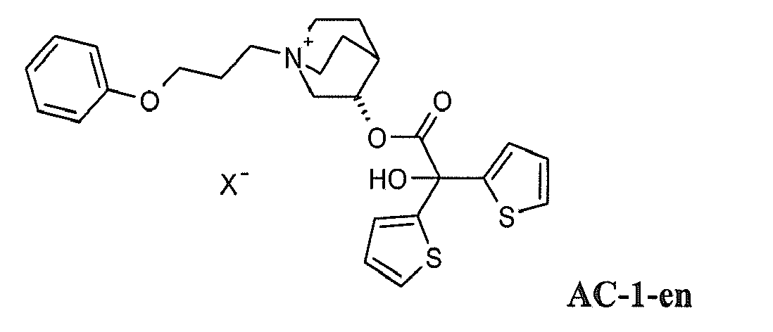

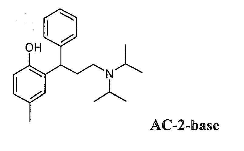
Weiterhin genannte Verbindungen sind:
- 2,2-Diphenylpropionsäuretropenolester-Methobromid
- 2,2-Diphenylpropionsäurescopinester-Methobromid
- 2-Fluor-2,2-Diphenylessigsäurescopinester-Methobromid
- 2-Fluor-2,2-Diphenylessigsäuretropenolester-Methobromid
- 3,3',4,4'-Tetrafluorbenzilsäuretropenolester-Methobromid
- 3,3',4,4'-Tetrafluorbenzilsäurescopinester-Methobromid
- 4,4'-Difluorbenzilsäuretropenolester-Methobromid
- 4,4'-Difluorbenzilsäurescopinester-Methobromid
- 3,3'-Difluorbenzilsäuretropenolester-Methobromid
- 3,3'-Difluorbenzilsäurescopinester-Methobromid
- 9-Hydroxy-fluoren-9-carbonsäuretropenolester-Methobromid
- 9-Fluor-fluoren-9-carbonsäuretropenolester-Methobromid
- 9-Hydroxy-fluoren-9-carbonsäurescopinester-Methobromid
- 9-Fluor-fluoren-9-carbonsäurescopinester-Methobromid
- 9-Methyl-fluoren-9-carbonsäuretropenolester-Methobromid
- 9-Methyl-fluoren-9-carbonsäurescopinester-Methobromid
- Benzilsäurecyclopropyltropinester-Methobromid
- 2,2-Diphenylpropionsäurecyclopropyltropinester-Methobromid
- 9-Hydroxy-xanthen-9-carbonsäurecyclopropyltropinester-Methobromid
- 9-Methyl-fluoren-9-carbonsäurecyclopropyltropinester-Methobromid
- 9-Methyl-xanthen-9-carbonsäurecyclopropyltropinester-Methobromid
- 9-Hydroxy-fluoren-9-carbonsäurecyclopropyltropinester-Methobromid
- 4,4'-Difluorbenzilsäuremethylestercyclopropyltropinester-Methobromid
- 9-Hydroxy-xanthen-9-carbonsäuretropenolester-Methobromid
- 9-Hydroxy-xanthen-9-carbonsäurescopinester-Methobromid
- 9-Methyl-xanthen-9-carbonsäuretropenolester-Methobromid
- 9-Methyl-xanthen-9-carbonsäurescopinester-Methobromid
- 9-Ethyl-xanthen-9-carbonsäuretropenolester-Methobromid
- 9-Difluormethyl-xanthen-9-carbonsäuretropenolester-Methobromid
- 9-Hydroxymethyl-xanthen-9-carbonsäurescopinester-Methobromid
- 2,2-diphenylpropionate methobromide
- 2,2-diphenylpropionate methobromide
- 2-fluoro-2,2-Diphenylessigsäurescopinester methobromide
- 2-fluoro-2,2-diphenylacetate methobromide
- 3,3 ', 4,4'-Tetrafluorbenzilsäuretropenolester methobromide
- 3,3 ', 4,4'-Tetrafluorbenzilsäurescopinester methobromide
- 4,4'-difluorobenzilate methobromide
- 4,4'-Difluorbenzilsäurescopinester methobromide
- 3,3'-difluorobenzilate methobromide
- 3,3'-Difluorbenzilsäurescopinester methobromide
- 9-hydroxy-fluorene-9-carbonsäuretropenolester methobromide
- 9-fluoro-fluorene-9-carbonsäuretropenolester methobromide
- 9-hydroxy-fluorene-9-carbonsäurescopinester methobromide
- 9-fluoro-fluorene-9-carbonsäurescopinester methobromide
- 9-methyl-fluorene-9-carbonsäuretropenolester methobromide
- 9-methyl-fluorene-9-carbonsäurescopinester methobromide
- Benzilsäurecyclopropyltropinester methobromide
- 2,2-Diphenylpropionsäurecyclopropyltropinester methobromide
- 9-hydroxy-xanthene-9-carbonsäurecyclopropyltropinester methobromide
- 9-methyl-fluorene-9-carbonsäurecyclopropyltropinester methobromide
- 9-methyl-xanthene-9-carbonsäurecyclopropyltropinester methobromide
- 9-hydroxy-fluorene-9-carbonsäurecyclopropyltropinester methobromide
- 4,4'-Difluorbenzilsäuremethylestercyclopropyltropinester methobromide
- 9-hydroxy-xanthene-9-carbonsäuretropenolester methobromide
- 9-hydroxy-xanthene-9-carbonsäurescopinester methobromide
- 9-methyl-xanthene-9-carbonsäuretropenolester methobromide
- 9-methyl-xanthene-9-carbonsäurescopinester methobromide
- 9-ethyl-xanthene-9-carbonsäuretropenolester methobromide
- 9-difluoromethyl-xanthene-9-carbonsäuretropenolester methobromide
- 9-hydroxymethyl-xanthene-9-carbonsäurescopinester methobromide
Die vorstehend genannten Verbindungen sind im Rahmen der vorliegenden Erfindung auch als Salze einsetzbar, in denen statt des Methobromids, die Salze Metho-X zur Anwendung gelangen, wobei X die vorstehend für X- genannten Bedeutungen haben kann.The abovementioned compounds can also be used in the context of the present invention as salts in which, instead of the methobromide, the salts Metho-X are used, where X may have the meanings given above for X - .
Als Corticosteroide gelangen hierbei vorzugsweise Verbindungen zur Anwendung, die ausgewählt sind aus der Gruppe bestehend aus Beclomethason, Betamethason, Budesonid, Butixocort, Ciclesonid, Deflazacort, Dexamethason, Etiprednol, Flunisolid, Fluticason,Preferred corticosteroids here are compounds which are selected from the group consisting of beclomethasone, betamethasone, budesonide, butixocort, ciclesonide, deflazacort, dexamethasone, etiprednol, flunisolide, fluticasone,
Loteprednol, Mometason, Prednisolon, Prednison, Rofleponid, Triamcinolon, RPR-106541, NS-126, ST-26 und
- 6,9-Difluor-17-[(2-furanylcarbonyl)oxy]-11-hydroxy-16-methyl-3-oxo-androsta-1,4-dien-17-carbothionsäure (S)-fluoromethylester
- 6,9-Difluor-11-hydroxy-16-methyl-3-oxo-17-propionyloxy-androsta-1,4-dien-17-carbothionsäure (S)-(2-oxo-tetrahydro-furan-3S-yl)ester,
- 6□,9□-difluoro-11□-hydroxy-16□-methyl-3-oxo-17□-(2,2,3,3-tertamethylcyclopropylcarbonyl)oxy-androsta-1,4-diene-17□-carbonsäure cyanomethyl ester
- 6,9-Difluoro-17 - [(2-furanylcarbonyl) oxy] -11-hydroxy-16-methyl-3-oxo-androsta-1,4-diene-17-carbothionic acid (S) -fluoromethyl ester
- 6,9-Difluoro-11-hydroxy-16-methyl-3-oxo-17-propionyloxy-androsta-1,4-diene-17-carbothioic acid (S) - (2-oxo-tetrahydrofuran-3S-yl) esters,
- □ 6, 9 -difluoro-11 □ □ □ -hydroxy-16 -methyl-3-oxo-17 □ - (2,2,3,3-tertamethylcyclopropylcarbonyl) oxy-androsta-1,4-diene-17-carboxylic acid □ cyanomethyl ester
Als PDE4-Inhibitoren gelangen hierbei vorzugsweise Verbindungen zur Anwendung, die ausgewählt sind aus der Gruppe bestehend aus Enprofyllin, Theophyllin, Roflumilast, Ariflo (Cilomilast), Tofimilast, Pumafentrin, Lirimilast, Arofyllin, Atizoram, D-4418, Bay-198004, BY343, CP-325,366, D-4396 (Sch-351591), AWD-12-281 (GW-842470), NCS-613, CDP-840, D-4418, PD-168787, T-440, T-2585, V-11294A, C1-1018, CDC-801, CDC-3052, D-22888, YM-58997, Z-15370 und
- N-(3,5-Dichloro-1-oxo-pyridin-4-yl)-4-difluormethoxy-3-cyclopropylmethoxybenzamid
- (-)p-[(4aR*,10bS*)-9-Ethoxy-1,2,3,4,4a,10b-hexahydro-8-methoxy-2-methylbenzo[s][1,6]naphthyridin-6-yl]-N,N-diisopropylbenzamid
- (R)-(+)-1-(4-Brombenzyl)-4-[(3-cyclopentyloxy)-4-methoxyphenyl]-2-pyrrolidon
- 3-(Cyclopentyloxy-4-methoxyphenyl)-1-(4-N'-[N-2-cyano-S-methylisothioureido]benzyl)-2-pyrrolidon
- cis[4-Cyano-4-(3-cyclopentyloxy-4-methoxyphenyl)cyclohexan-1-carbonsäure]
- 2-carbomethoxy-4-cyano-4-(3-cyclopropylmethoxy-4-difluoromethoxyphenyl)cyclohexan-1-on
- cis[4-Cyano-4-(3-cyclopropylmethoxy-4-difluormethoxyphenyl)cyclohexan-1-ol]
- (R)-(+)-Ethyl[4-(3-cyclopentyloxy-4-methoxyphenyl)pyrrolidin-2-yliden]acetat
- (S)-(-)-Ethyl[4-(3-cyclopentyloxy-4-methoxyphenyl)pyrrolidin-2-yliden]acetat
- 9-Cyclopentyl-5,6-dihydro-7-ethyl-3-(2-thienyl)-9H-pyrazolo[3,4-c]-1,2,4-triazolo[4,3-a]pyridin
- 9-Cyclopentyl-5,6-dihydro-7-ethyl-3-(tert-butyl)-9H-pyrazolo[3,4-c]-1,2,4-triazolo[4,3-a]pyridin
- N- (3,5-dichloro-1-oxo-pyridin-4-yl) -4-difluoromethoxy-3-cyclopropylmethoxybenzamid
- (-) p - [(4 a R *, 10 b S *) - 9-ethoxy-1,2,3,4,4a, 10b-hexahydro-8-methoxy-2-methylbenzo [s] [1,6 ] naphthyridin-6-yl] -N, N-diisopropylbenzamide
- (R) - (+) - 1- (4-bromobenzyl) -4 - [(3-cyclopentyloxy) -4-methoxyphenyl] -2-pyrrolidone
- 3- (cyclopentyloxy-4-methoxyphenyl) -1- (4-N '- [N-2-cyano-S-methylisothioureido] benzyl) -2-pyrrolidone
- cis [4-cyano-4- (3-cyclopentyloxy-4-methoxyphenyl) cyclohexane-1-carboxylic acid]
- 2-carbomethoxy-4-cyano-4- (3-cyclopropylmethoxy-4-difluoromethoxyphenyl) cyclohexan-1-one
- cis [4-cyano-4- (3-cyclopropylmethoxy-4-difluoromethoxyphenyl) cyclohexan-1-ol]
- (R) - (+) - ethyl [4- (3-cyclopentyloxy-4-methoxyphenyl) pyrrolidin-2-ylidene] acetate
- (S) - (-) - ethyl acetate [4- (3-cyclopentyloxy-4-methoxyphenyl) pyrrolidin-2-ylidene]
- 9-cyclopentyl-5,6-dihydro-7-ethyl-3- (2-thienyl) -9 H -pyrazolo [3,4-c] -1,2,4-triazolo [4,3-a] pyridine
- 9-Cyclopentyl-5,6-dihydro-7-ethyl-3- ( tert -butyl) -9 H -pyrazolo [3,4-c] -1,2,4-triazolo [4,3-a] pyridine
Als LTD4-Antagonisten gelangen hierbei vorzugsweise Verbindungen zur Anwendung, die ausgewählt sind aus der Gruppe bestehend aus Montelukast, Pranlukast, Zafirlukast, MCC-847 (ZD-3523), MN-001, MEN-91507 (LM-1507), VUF-5078, VUF-K-8707, L-733321 und
- 1-(((R)-(3-(2-(6,7-Difluor-2-quinolinyl)ethenyl)phenyl)-3-(2-(2-hydroxy-2-propyl)phenyl)thio)methylcyclopropan-essigsäure,
- 1-(((1(R)-3(3-(2-(2,3-Dichlorthieno[3,2-b]pyridin-5-yI)-(E)-ethenyl)phenyl)-3-(2-(1-hydroxy-1-methylethyl)phenyl)propyl)thio)methyl)cyclopropanessigsäure
- [2-[[2-(4-tert-Butyl-2-thiazolyl)-5-benzofuranyl]oxymethyl]phenyl]essigsäure
- 1 - (((R) - (3- (2- (6,7-difluoro-2-quinolinyl) ethenyl) phenyl) -3- (2- (2-hydroxy-2-propyl) phenyl) thio) methylcyclopropan- acetic acid,
- 1 - (((1 (R) -3 (3- (2- (2,3-Dichlorothieno [3,2-b] pyridin-5-yI) - (E) -ethenyl) phenyl) -3- (2 - (1-hydroxy-1-methylethyl) phenyl) propyl) thio) methyl) cyclopropane acetic acid
- [2 - [[2- (4-tert-butyl-2-thiazolyl) -5-benzofuranyl] oxymethyl] phenyl] acetic acid
Als EGFR-Hemmer gelangen hierbei vorzugsweise Verbindungen zur Anwendung, die ausgewählt sind aus der Gruppe bestehend aus Cetuximab, Trastuzumab, ABX-EGF, Mab ICR-62 und
- 4-[(3-Chlor-4-fluorphenyl)amino]-6-{[4-(morpholin-4-yl)-1-oxo-2-buten-1-yl]amino}-7-cyclopropylmethoxy-chinazolin
- 4-[(3-Chlor-4-fluorphenyl)amino]-6-{[4-(N,N-diethylamino)-1-oxo-2-buten-1-yl]amino}-7-cyclopropylmethoxy-chinazolin
- 4-[(3-Chlor-4-fluorphenyl)amino]-6-{[4-(N,N-dimethylamino)-1-oxo-2-buten-1-yl]amino}-7-cyclopropylmethoxy-chinazolin
- 4-[(R)-(1-Phenyl-ethyl)amino]-6-{[4-(morpholin-4-yl)-1-oxo-2-buten-1-yl]amino}-7-cyclopentyloxy-chinazolin
- 4-[(3-Chlor-4-fluor-phenyl)amino]-6-{[4-((R)-6-methyl-2-oxo-morpholin-4-yl)-1-oxo-2-buten-1-yl]amino}-7-cyclopropylmethoxy-chinazolin
- 4-[(3-Chlor-4-fluor-phenyl)amino]-6-{[4-((R)-6-methyl-2-oxo-morpholin-4-yl)-1-oxo-2-buten-1-yl]amino}-7-[(S)-(tetrahydrofuran-3-yl)oxy]-chinazolin
- 4-[(3-Chlor-4-fluor-phenyl)amino]-6-{[4-((R)-2-methoxymethyl-6-oxo-morpholin-4-yl)-1-oxo-2-buten-1-yl]amino}-7-cyclopropylmethoxy-chinazolin
- 4-[(3-Chlor-4-fluor-phenyl)amino]-6-[2-((S)-6-methyl-2-oxo-morpholin-4-yl)-ethoxy]-7-methoxy-chinazolin
- 4-[(3-Chlor-4-fluorphenyl)amino]-6-({4-[N-(2-methoxy-ethyl)-N-methyl-amino]-1-oxo-2-buten-1-yl}amino)-7-cyclopropylmethoxy-chinazolin
- 4-[(3-Chlor-4-fluorphenyl)amino]-6-{[4-(N,N-dimethylamino)-1-oxo-2-buten-1-yl]amino}-7-cyclopentyloxy-chinazolin
- 4-[(R)-(1-Phenyl-ethyl)amino]-6-{[4-(N,N-bis-(2-methoxy-ethyl)-amino)-1-oxo-2-buten-1-yl]amino}-7-cyclopropylmethoxy-chinazolin
- 4-[(R)-(1-Phenyl-ethyl)amino]-6-({4-[N-(2-methoxy-ethyl)-N-ethyl-amino]-1-oxo-2-buten-1-yl}amino)-7-cyclopropylmethoxy-chinazolin
- 4-[(R)-(1-Phenyl-ethyl)amino]-6-({4-[N-(2-methoxy-ethyl)-N-methyl-amino]-1-oxo-2-buten-1-yl}amino)-7-cyclopropylmethoxy-chinazolin
- 4-[(R)-(1-Phenyl-ethyl)amino]-6-({4-[N-(tetrahydropyran-4-yl)-N-methyl-amino]-1-oxo-2-buten-1-yl}amino)-7-cyclopropylmethoxy-chinazolin
- 4-[(3-Chlor-4-fluorphenyl)amino]-6-{[4-(N,N-dimethylamino)-1-oxo-2-buten-1-yl]amino}-7-((R)-tetrahydrofuran-3-yloxy)-chinazolin
- 4-[(3-Chlor-4-fluorphenyl)amino]-6-{[4-(N,N-dimethylamino)-1-oxo-2-buten-1-yl]amino}-7-((S)-tetrahydrofuran-3-yloxy)-chinazolin
- 4-[(3-Chlor-4-fluorphenyl)amino]-6-({4-[N-(2-methoxy-ethyl)-N-methyl-amino]-1-oxo-2-buten-1-yl}amino)-7-cyclopentyloxy-chinazolin
- 4-[(3-Chlor-4-fluorphenyl)amino]-6-{[4-(N-cyclopropyl-N-methyl-amino)-1-oxo-2-buten-1-yl]amino}-7-cyclopentyloxy-chinazolin
- 4-[(3-Chlor-4-fluorphenyl)amino]-6-{[4-(N,N-dimethylamino)-1-oxo-2-buten-1-yl]amino}-7-[(R)-(tetrahydrofuran-2-yl)methoxy]-chinazolin
- 4-[(3-Chlor-4-fluorphenyl)amino]-6-{[4-(N,N-dimethylamino)-1-oxo-2-buten-1-yl]amino}-7-[(S)-(tetrahydrofuran-2-yl)methoxy]-chinazolin
- 4-[(3-Ethinyl-phenyl)amino]-6,7-bis-(2-methoxy-ethoxy)-chinazolin
- 4-[(3-Chlor-4-fluorphenyl)amino]-7-[3-(morpholin-4-yl)-propyloxy]-6-[(vinylcarbonyl)amino]-chinazolin
- 4-[(R)-(1-Phenyl-ethyl)amino]-6-(4-hydroxy-phenyl)-7H-pyrrolo[2,3-d]pyrimidin
- 3-Cyano-4-[(3-chlor-4-fluorphenyl)amino]-6-{[4-(N,N-dimethylamino)-1-oxo-2-buten-1-yl]amino}-7-ethoxy-chinolin
- 4-{[3-Chlor-4-(3-fluor-benzyloxy)-phenyl]amino}-6-(5-{[(2-methansulfonylethyl)amino]methyl}-furan-2-yl)chinazolin
- 4-[(R)-(1-Phenyl-ethyl)amino]-6-{[4-((R)-6-methyl-2-oxo-morpholin-4-yl)-1-oxo-2-buten-1-yl]amino}-7-methoxy-chinazolin
- 4-[(3-Chlor-4-fluorphenyl)amino]-6-{[4-(morpholin-4-yl)-1-oxo-2-buten-1-yl]amino}-7-[(tetrahydrofuran-2-yl)methoxy]-chinazolin
- 4-[(3-Chlor-4-fluorphenyl)amino]-6-({4-[N,N-bis-(2-methoxy-ethyl)-amino]-1-oxo-2-buten-1-yl}amino)-7-[(tetrahydrofuran-2-yl)methoxy]-chinazolin
- 4-[(3-Ethinyl-phenyl)amino]-6-{[4-(5,5-dimethyl-2-oxo-morpholin-4-yl)-1-oxo-2-buten-1-yl]amino}-chinazolin
- 4-[(3-Chlor-4-fluor-phenyl)amino]-6-[2-(2,2-dimethyl-6-oxo-morpholin-4-yl)-ethoxy]-7-methoxy-chinazolin
- 4-[(3-Chlor-4-fluor-phenyl)amino]-6-[2-(2,2-dimethyl-6-oxo-morpholin-4-yl)-ethoxy]-7-[(R)-(tetrahydrofuran-2-yl)methoxy]-chinazolin
- 4-[(3-Chlor-4-fluor-phenyl)amino]-7-[2-(2,2-dimethyl-6-oxo-morpholin-4-yl)-ethoxy]-6-[(S)-(tetrahydrofuran-2-yl)methoxy]-chinazolin
- 4-[(3-Chlor-4-fluor-phenyl)amino]-6-{2-[4-(2-oxo-morpholin-4-yl)-piperidin-1-yl]-ethoxy}-7-methoxy-chinazolin
- 4-[(3-Chlor-4-fluor-phenyl)amino]-6-[1-(tert.-butyloxycarbonyl)-piperidin-4-yloxy]-7-methoxy-chinazolin
- 4-[(3-Chlor-4-fluor-phenyl)amino]-6-(trans-4-amino-cyclohexan-1-yloxy)-7-methoxychinazolin
- 4-[(3-Chlor-4-fluor-phenyl)amino]-6-(trans-4-methansulfonylamino-cyclohexan-1-yloxy)-7-methoxy-chinazolin
- 4-[(3-Chlor-4-fluor-phenyl)amino]-6-(tetrahydropyran-3-yloxy)-7-methoxy-chinazolin
- 4-[(3-Chlor-4-fluor-phenyl)amino]-6-(1-methyl-piperidin-4-yloxy)-7-methoxy-chinazolin
- 4-[(3-Chlor-4-fluor-phenyl)amino]-6-{1-[(morpholin-4-yl)carbonyl]-piperidin-4-yloxy}-7-methoxy-chinazolin
- 4-[(3-Chlor-4-fluor-phenyl)amino]-6-1-[(methoxymethyl)carbonyl]-piperidin-4-yloxy}-7-methoxy-chinazolin
- 4-[(3-Chlor-4-fluor-phenyl)amino]-6-(piperidin-3-yloxy)-7-methoxy-chinazolin
- 4-[(3-Chlor-4-fluor-phenyl)amino]-6-[1-(2-acetylamino-ethyl)-piperidin-4-yloxy]-7-methoxy-chinazolin
- 4-[(3-Chlor-4-fluor-phenyl)amino]-6-(tetrahydropyran-4-yloxy)-7-ethoxy-chinazolin
- 4-[(3-Chlor-4-fluor-phenyl)amino]-6-((S)-tetrahydrofuran-3-yloxy)-7-hydroxy-chinazolin
- 4-[(3-Chlor-4-fluor-phenyl)amino]-6-(tetrahydropyran-4-yloxy)-7-(2-methoxy-ethoxy)-chinazolin
- 4-[(3-Chlor-4-fluor-phenyl)amino]-6-{trans-4-[(dimethylamino)sulfonylamino]-cyclohexan-1-yloxy}-7-methoxy-chinazolin
- 4-[(3-Chlor-4-fluor-phenyl)amino]-6-{trans-4-[(morpholin-4-yl)carbonylamino]-cyclohexan-1-yloxy}-7-methoxy-chinazolin
- 4-[(3-Chlor-4-fluor-phenyl)amino]-6-{trans-4-[(morpholin-4-yl)sulfonylamino]-cyclohexan-1-yloxy}-7-methoxy-chinazolin
- 4-[(3-Chlor-4-fluor-phenyl)amino]-6-(tetrahydropyran-4-yloxy)-7-(2-acetylaminoethoxy)-chinazolin
- 4-[(3-Chlor-4-fluor-phenyl)amino]-6-(tetrahydropyran-4-yloxy)-7-(2-methansulfonylamino-ethoxy)-chinazolin
- 4-[(3-Chlor-4-fluor-phenyl)amino]-6-{1-[(piperidin-1-yl)carbonyl]-piperidin-4-yloxy}-7-methoxy-chinazolin
- 4-[(3-Chlor-4-fluor-phenyl)amino]-6-(1-aminocarbonylmethyl-piperidin-4-yloxy)-7-methoxy-chinazolin
- 4-[(3-Chlor-4-fluor-phenyl)amino]-6-(cis-4-{N-[(tetrahydropyran-4-yl)carbonyl]-N-methyl-amino}-cyclohexan-1-yloxy)-7-methoxy-chinazolin
- 4-[(3-Chlor-4-fluor-phenyl)amino]-6-(cis-4-{N-[(morpholin-4-yl)carbonyl]-N-methyl-amino}-cyclohexan-1-yloxy)-7-methoxy-chinazolin
- 4-[(3-Chlor-4-fluor-phenyl)amino]-6-(cis-4-{N-[(morpholin-4-yl)sulfonyl]-N-methyl-amino}-cyclohexan-1-yloxy)-7-methoxy- chinazolin
- 4-[(3-Chlor-4-fluor-phenyl)amino]-6-(trans-4-ethansulfonylamino-cyclohexan-1-yloxy)-7-methoxy-chinazolin
- 4-[(3-Chlor-4-fluor-phenyl)amino]-6-(1-methansulfonyl-piperidin-4-yloxy)-7-ethoxy-chinazolin
- 4-[(3-Chlor-4-fluor-phenyl)amino]-6-(1-methansulfonyl-piperidin-4-yloxy)-7-(2-methoxy-ethoxy)-chinazolin
- 4-[(3-Chlor-4-fluor-phenyl)amino]-6-[1-(2-methoxy-acetyl)-piperidin-4-yloxy]-7-(2-methoxy-ethoxy)-chinazolin
- 4-[(3-Chlor-4-fluor-phenyl)amino]-6-(cis-4-acetylamino-cyclohexan-1-yloxy)-7-methoxychinazolin
- 4-[(3-Ethinyl-phenyl)amino]-6-[1-(tert.-butyloxycarbonyl)-piperidin-4-yloxy]-7-methoxychinazolin
- 4-[(3-Ethinyl-phenyl)amino]-6-(tetrahydropyran-4-yloxy]-7-methoxy-chinazolin
- 4-[(3-Chlor-4-fluor-phenyl)amino]-6-(cis-4-{N-[(piperidin-1-yl)carbonyl]-N-methylamino}-cyclohexan-1-yloxy)-7-methoxy-chinazolin
- 4-[(3-Chlor-4-fluor-phenyl)amino]-6-(cis-4-{N-[(4-methyl-piperazin-1-yl)carbonyl]-N-methyl-amino}-cyclohexan-1-yloxy)-7-methoxy-chinazolin
- 4-[(3-Chlor-4-fluor-phenyl)amino]-6-{cis-4-[(morpholin-4-yl)carbonylamino]-cyclohexan-1-yloxy}-7-methoxy-chinazolin
- 4-[(3-Chlor-4-fluor-phenyl)amino]-6-{1-[2-(2-oxopyrrolidin-1-yl)ethyl]-piperidin-4-yloxy}-7-methoxy-chinazolin
- 4-[(3-Chlor-4-fluor-phenyl)amino]-6-{1-[(morpholin-4-yl)carbonyl]-piperidin-4-yloxy}-7-(2-methoxy-ethoxy)-chinazolin
- 4-[(3-Ethinyl-phenyl)amino]-6-(1-acetyl-piperidin-4-yloxy)-7-methoxy-chinazolin
- 4-[(3-Ethinyl-phenyl)amino]-6-(1-methyl-piperidin-4-yloxy)-7-methoxy-chinazolin
- 4-[(3-Ethinyl-phenyl)amino]-6-(1-methansulfonyl-piperidin-4-yloxy)-7-methoxychinazolin
- 4-[(3-Chlor-4-fluor-phenyl)amino]-6-(1-methyl-piperidin-4-yloxy)-7(2-methoxy-ethoxy)-chinazolin
- 4-[(3-Chlor-4-fluor-phenyl)amino]-6-(1-isopropyloxycarbonyl-piperidin-4-yloxy)-7-methoxy-chinazolin
- 4-[(3-Chlor-4-fluor-phenyl)amino]-6-(cis-4-methylamino-cyclohexan-1-yloxy)-7-methoxy-chinazolin
- 4-[(3-Chlor-4-fluor-phenyl)amino]-6-{cis-4-[N-(2-methoxy-acetyl)-N-methyl-amino]-cyclohexan-1-yloxy}-7-methoxy-chinazolin
- 4-[(3-Ethinyl-phenyl)amino]-6-(piperidin-4-yloxy)-7-methoxy-chinazolin
- 4-[(3-Ethinyl-phenyl)amino]-6-[1-(2-methoxy-acetyl)-piperidin-4-yloxy]-7-methoxychinazolin
- 4-[(3-Ethinyl-phenyl)amino]-6-{1-[(morpholin-4-yl)carbonyl]-piperidin-4-yloxy}-7-methoxy-chinazolin
- 4-[(3-Chlor-4-fluor-phenyl)amino]-6-{1-[(cis-2,6-dimethyl-morpholin-4-yl)carbonyl]-piperidin-4-yloxy} -7-methoxy-chinazolin
- 4-[(3-Chlor-4-fluor-phenyl)amino]-6-{1-[(2-methyl-morpholin-4-yl)carbonyl]-piperidin-4-yloxy}-7-methoxy-chinazolin
- 4-[(3-Chlor-4-fluor-phenyl)amino]-6-{1-[(S,S)-(2-oxa-5-aza-bicyclo[2.2.1]hept-5-yl)carbonyl]-piperidin-4-yloxy}-7-methoxy-chinazolin
- 4-[(3-Chlor-4-fluor-phenyl)amino]-6-{1-[(N-methyl-N-2-methoxyethyl-amino)carbonyl]-piperidin-4-yloxy}-7-methoxy-chinazolin
- 4-[(3-Chlor-4-fluor-phenyl)amino]-6-(1-ethyl-piperidin-4-yloxy)-7-methoxy-chinazolin
- 4-[(3-Chlor-4-fluor-phenyl)amino]-6-{1-[(2-methoxyethyl)carbonyl]-piperidin-4-yloxy}-7-methoxy-chinazolin
- 4-[(3-Chlor-4-fluor-phenyl)amino]-6-{1-[(3-methoxypropyl-amino)-carbonyl]-piperidin-4-yloxy}-7-methoxy-chinazolin
- 4-[(3-Chlor-4-fluor-phenyl)amino]-6-[cis-4-(N-methansulfonyl-N-methyl-amino)-cyclohexan-1-yloxy]-7-methoxy-chinazolin
- 4-[(3-Chlor-4-fluor-phenyl)amino]-6-[cis-4-(N-acetyl-N-methyl-amino)-cyclohexan-1-yloxy]-7-methoxy-chinazolin
- 4-[(3-Chlor-4-fluor-phenyl)amino]-6-(trans-4-methylamino-cyclohexan-1-yloxy)-7-methoxy-chinazolin
- 4-[(3-Chlor-4-fluor-phenyl)amino]-6-[trans-4-(N-methansulfonyl-N-methyl-amino)-cyclohexan-1-yloxy]-7-methoxy-chinazolin
- 4-[(3-Chlor-4-fluor-phenyl)amino]-6-(trans-4-dimethylamino-cyclohexan-1-yloxy)-7-methoxy-chinazolin
- 4-[(3-Chlor-4-fluor-phenyl)amino]-6-(trans-4-{N-[(morpholin-4-yl)carbonyl]-N-methylamino}-cyclohexan-1-yloxy)-7-methoxy-chinazolin
- 4-[(3-Chlor-4-fluor-phenyl)amino]-6-[2-(2,2-dimethyl-6-oxo-morpholin-4-yl)-ethoxy]-7-[(S)-(tetrahydrofuran-2-yl)methoxy]-chinazolin
- 4-[(3-Chlor-4-fluor-phenyl)amino]-6-(1-methansulfonyl-piperidin-4-yloxy)-7-methoxychinazolin
- 4-[(3-Chlor-4-fluor-phenyl)amino]-6-(1-cyano-piperidin-4-yloxy)-7-methoxy-chinazolin
- 4 - [(3-chloro-4-fluorophenyl) amino] -6 - {[4- (morpholin-4-yl) -1-oxo-2-buten-1-yl] amino} -7-cyclopropylmethoxy-quinazoline
- 4 - [(3-chloro-4-fluorophenyl) amino] -6 - {[4- (N, N-diethylamino) -1-oxo-2-buten-1-yl] amino} -7-cyclopropylmethoxy-quinazoline
- 4 - [(3-chloro-4-fluorophenyl) amino] -6 - {[4- (N, N-dimethylamino) -1-oxo-2-buten-1-yl] amino} -7-cyclopropylmethoxy-quinazoline
- 4 - [(R) - (1-phenyl-ethyl) amino] -6 - {[4- (morpholin-4-yl) -1-oxo-2-buten-1-yl] amino} -7-cyclopentyloxy- quinazoline
- 4 - [(3-chloro-4-fluoro-phenyl) amino] -6 - {[4 - ((R) -6-methyl-2-oxo-morpholin-4-yl) -1-oxo-2-butene -1-yl] amino} -7-cyclopropylmethoxy-quinazoline
- 4 - [(3-chloro-4-fluoro-phenyl) amino] -6 - {[4 - ((R) -6-methyl-2-oxo-morpholine-4-yl) -1-oxo-2-butene -1-yl] amino} -7 - [(S) - (tetrahydrofuran-3-yl) oxy] -quinazoline
- 4 - [(3-chloro-4-fluoro-phenyl) amino] -6 - {[4 - ((R) -2-methoxymethyl-6-oxo-morpholin-4-yl) -1-oxo-2-butene -1-yl] amino} -7-cyclopropylmethoxy-quinazoline
- 4 - [(3-chloro-4-fluoro-phenyl) amino] -6- [2 - ((S) -6-methyl-2-oxo-morpholin-4-yl) -ethoxy] -7-methoxy-quinazoline
- 4 - [(3-chloro-4-fluorophenyl) amino] -6 - ({4- [N- (2-methoxy-ethyl) -N-methyl-amino] -1-oxo-2-buten-1-yl } amino) -7-cyclopropylmethoxy-quinazoline
- 4 - [(3-chloro-4-fluorophenyl) amino] -6 - {[4- (N, N-dimethylamino) -1-oxo-2-buten-1-yl] amino} -7-cyclopentyloxy-quinazoline
- 4 - [(R) - (1-phenyl-ethyl) amino] -6 - {[4- (N, N-bis- (2-methoxy-ethyl) -amino) -1-oxo-2-buten-1 yl] amino} -7-cyclopropylmethoxy-quinazoline
- 4 - [(R) - (1-phenyl-ethyl) amino] -6 - ({4- [N- (2-methoxy-ethyl) -N-ethyl-amino] -1-oxo-2-buten-1 yl} amino) -7-cyclopropylmethoxy-quinazoline
- 4 - [(R) - (1-phenyl-ethyl) amino] -6 - ({4- [N- (2-methoxy-ethyl) -N-methyl-amino] -1-oxo-2-buten-1 yl} amino) -7-cyclopropylmethoxy-quinazoline
- 4 - [(R) - (1-phenyl-ethyl) amino] -6 - ({4- [N- (tetrahydropyran-4-yl) -N-methyl-amino] -1-oxo-2-buten-1 yl} amino) -7-cyclopropylmethoxy-quinazoline
- 4 - [(3-chloro-4-fluorophenyl) amino] -6 - {[4- (N, N-dimethylamino) -1-oxo-2-buten-1-yl] amino} -7 - ((R) -tetrahydrofuran-3-yloxy) -quinazoline
- 4 - [(3-chloro-4-fluorophenyl) amino] -6 - {[4- (N, N-dimethylamino) -1-oxo-2-buten-1-yl] amino} -7 - ((S) -tetrahydrofuran-3-yloxy) -quinazoline
- 4 - [(3-chloro-4-fluorophenyl) amino] -6 - ({4- [N- (2-methoxy-ethyl) -N-methyl-amino] -1-oxo-2-buten-1-yl } amino) -7-cyclopentyloxy-quinazoline
- 4 - [(3-chloro-4-fluorophenyl) amino] -6 - {[4- (N-cyclopropyl-N-methyl-amino) -1-oxo-2-buten-1-yl] amino} -7- cyclopentyloxy-quinazoline
- 4 - [(3-chloro-4-fluorophenyl) amino] -6 - {[4- (N, N-dimethylamino) -1-oxo-2-buten-1-yl] amino} -7 - [(R) - (tetrahydrofuran-2-yl) methoxy] -quinazoline
- 4 - [(3-chloro-4-fluorophenyl) amino] -6 - {[4- (N, N-dimethylamino) -1-oxo-2-buten-1-yl] amino} -7 - [(S) - (tetrahydrofuran-2-yl) methoxy] -quinazoline
- 4 - [(3-ethynyl-phenyl) amino] -6,7-bis- (2-methoxy-ethoxy) -quinazoline
- 4 - [(3-chloro-4-fluorophenyl) amino] -7- [3- (morpholin-4-yl) propyloxy] -6 - [(vinylcarbonyl) amino] -quinazoline
- 4 - [(R) - (1-phenyl-ethyl) amino] -6- (4-hydroxy-phenyl) -7H-pyrrolo [2,3-d] pyrimidine
- 3-Cyano-4 - [(3-chloro-4-fluorophenyl) amino] -6 - {[4- (N, N-dimethylamino) -1-oxo-2-buten-1-yl] amino} -7- ethoxy-quinoline
- 4 - {[3-chloro-4- (3-fluoro-benzyloxy) -phenyl] amino} -6- (5 - {[(2-methanesulfonylethyl) amino] methyl} -furan-2-yl) quinazoline
- 4 - [(R) - (1-phenyl-ethyl) amino] -6 - {[4 - ((R) -6-methyl-2-oxo-morpholin-4-yl) -1-oxo-2-butene -1-yl] amino} -7-methoxy-quinazoline
- 4 - [(3-chloro-4-fluorophenyl) amino] -6 - {[4- (morpholin-4-yl) -1-oxo-2-buten-1-yl] amino} -7 - [(tetrahydro-furan- 2-yl) methoxy] -quinazoline
- 4 - [(3-chloro-4-fluorophenyl) amino] -6 - ({4- [N, N-bis- (2-methoxy-ethyl) -amino] -1-oxo-2-buten-1-yl } amino) -7 - [(tetrahydrofuran-2yl) methoxy] -quinazoline
- 4 - [(3-ethynyl-phenyl) amino] -6 - {[4- (5,5-dimethyl-2-oxo-morpholin-4-yl) -1-oxo-2-buten-1-yl] amino } -quinazoline
- 4 - [(3-chloro-4-fluoro-phenyl) amino] -6- [2- (2,2-dimethyl-6-oxo-morpholin-4-yl) -ethoxy] -7-methoxy-quinazoline
- 4 - [(3-chloro-4-fluoro-phenyl) amino] -6- [2- (2,2-dimethyl-6-oxo-morpholin-4-yl) -ethoxy] -7 - [(R) - (tetrahydrofuran-2-yl) methoxy] -quinazoline
- 4 - [(3-chloro-4-fluoro-phenyl) amino] -7- [2- (2,2-dimethyl-6-oxo-morpholin-4-yl) -ethoxy] -6 - [(S) - (tetrahydrofuran-2-yl) methoxy] -quinazoline
- 4 - [(3-chloro-4-fluoro-phenyl) amino] -6- {2- [4- (2-oxo-morpholin-4-yl) piperidin-1-yl] -ethoxy} -7-methoxy -quinazoline
- 4 - [(3-chloro-4-fluoro-phenyl) amino] -6- [1- (tert.-butyloxycarbonyl) -piperidin-4-yloxy] -7-methoxy-quinazoline
- 4 - [(3-chloro-4-fluoro-phenyl) amino] -6- (trans-4-amino-cyclohexan-1-yloxy) -7-methoxyquinazoline
- 4 - [(3-chloro-4-fluoro-phenyl) amino] -6- (trans-4-methanesulfonylamino-cyclohexane-1-yloxy) -7-methoxy-quinazoline
- 4 - [(3-chloro-4-fluoro-phenyl) amino] -6- (tetrahydropyran-3-yloxy) -7-methoxy-quinazoline
- 4 - [(3-chloro-4-fluoro-phenyl) amino] -6- (1-methyl-piperidin-4-yloxy) -7-methoxy-quinazoline
- 4 - [(3-chloro-4-fluoro-phenyl) amino] -6- {1 - [(morpholin-4-yl) carbonyl] piperidin-4-yloxy} -7-methoxy-quinazoline
- 4 - [(3-chloro-4-fluoro-phenyl) amino] -6-1 - [(methoxymethyl) carbonyl] piperidin-4-yloxy} -7-methoxy-quinazoline
- 4 - [(3-chloro-4-fluoro-phenyl) amino] -6- (piperidin-3-yloxy) -7-methoxy-quinazoline
- 4 - [(3-chloro-4-fluoro-phenyl) amino] -6- [1- (2-acetylamino-ethyl) -piperidin-4-yloxy] -7-methoxy-quinazoline
- 4 - [(3-chloro-4-fluoro-phenyl) amino] -6- (tetrahydropyran-4-yloxy) -7-ethoxy-quinazoline
- 4 - [(3-chloro-4-fluoro-phenyl) amino] -6 - ((S) -tetrahydrofuran-3-yloxy) -7-hydroxy-quinazoline
- 4 - [(3-chloro-4-fluoro-phenyl) amino] -6- (tetrahydropyran-4-yloxy) -7- (2-methoxy-ethoxy) -quinazoline
- 4 - [(3-chloro-4-fluoro-phenyl) amino] -6- {trans-4 - [(dimethylamino) sulfonylamino] -cyclohexan-1-yloxy} -7-methoxy-quinazoline
- 4 - [(3-chloro-4-fluoro-phenyl) amino] -6- {trans-4 - [(morpholin-4-yl) carbonylamino] cyclohexane-1-yloxy} -7-methoxy-quinazoline
- 4 - [(3-chloro-4-fluoro-phenyl) amino] -6- {trans-4 - [(morpholin-4-yl) sulfonylamino] -cyclohexan-1-yloxy} -7-methoxy-quinazoline
- 4 - [(3-chloro-4-fluoro-phenyl) amino] -6- (tetrahydropyran-4-yloxy) -7- (2-acetylaminoethoxy) quinazoline
- 4 - [(3-chloro-4-fluoro-phenyl) amino] -6- (tetrahydropyran-4-yloxy) -7- (2-methanesulfonylamino-ethoxy) -quinazoline
- 4 - [(3-chloro-4-fluoro-phenyl) amino] -6- {1 - [(piperidin-1-yl) carbonyl] piperidin-4-yloxy} -7-methoxy-quinazoline
- 4 - [(3-chloro-4-fluoro-phenyl) amino] -6- (1-aminocarbonylmethyl-piperidin-4-yloxy) -7-methoxy-quinazoline
- 4 - [(3-chloro-4-fluoro-phenyl) amino] -6- (cis-4- {N - [(tetrahydropyran-4-yl) carbonyl] -N-methyl-amino} -cyclohexan-1-yloxy ) -7-methoxy-quinazoline
- 4 - [(3-chloro-4-fluoro-phenyl) amino] -6- (cis-4- {N - [(morpholin-4-yl) carbonyl] -N-methyl-amino} -cyclohexan-1-yloxy ) -7-methoxy-quinazoline
- 4 - [(3-chloro-4-fluoro-phenyl) amino] -6- (cis-4- {N - [(morpholin-4-yl) sulfonyl] -N-methyl-amino} -cyclohexan-1-yloxy ) -7-methoxy-quinazoline
- 4 - [(3-chloro-4-fluoro-phenyl) amino] -6- (trans-4-ethanesulphonylamino-cyclohexan-1-yloxy) -7-methoxy-quinazoline
- 4 - [(3-chloro-4-fluoro-phenyl) amino] -6- (1-methanesulfonyl-piperidin-4-yloxy) -7-ethoxy-quinazoline
- 4 - [(3-chloro-4-fluoro-phenyl) amino] -6- (1-methanesulfonyl-piperidin-4-yloxy) -7- (2-methoxy-ethoxy) -quinazoline
- 4 - [(3-chloro-4-fluoro-phenyl) amino] -6- [1- (2-methoxy-acetyl) -piperidin-4-yloxy] -7- (2-methoxy-ethoxy) -quinazoline
- 4 - [(3-chloro-4-fluoro-phenyl) amino] -6- (cis-4-acetylamino-cyclohexan-1-yloxy) -7-methoxyquinazoline
- 4 - [(3-ethynyl-phenyl) amino] -6- [1- (tert.-butyloxycarbonyl) -piperidin-4-yloxy] -7-methoxyquinazoline
- 4 - [(3-ethynyl-phenyl) amino] -6- (tetrahydropyran-4-yloxy] -7-methoxy-quinazoline
- 4 - [(3-chloro-4-fluoro-phenyl) amino] -6- (cis-4- {N - [(piperidin-1-yl) carbonyl] -N-methylamino} -cyclohexan-1-yloxy) - 7-methoxy-quinazoline
- 4 - [(3-chloro-4-fluoro-phenyl) amino] -6- (cis-4- {N - [(4-methyl-piperazin-1-yl) carbonyl] -N-methyl-amino} -cyclohexane -1-yloxy) -7-methoxy-quinazoline
- 4 - [(3-chloro-4-fluoro-phenyl) amino] -6- {cis-4 - [(morpholin-4-yl) carbonylamino] cyclohexane-1-yloxy} -7-methoxy-quinazoline
- 4 - [(3-chloro-4-fluoro-phenyl) amino] -6- {1- [2- (2-oxopyrrolidin-1-yl) ethyl] piperidin-4-yloxy} -7-methoxy-quinazoline
- 4 - [(3-chloro-4-fluoro-phenyl) amino] -6- {1 - [(morpholin-4-yl) carbonyl] piperidin-4-yloxy} -7- (2-methoxy-ethoxy) - quinazoline
- 4 - [(3-ethynyl-phenyl) amino] -6- (1-acetyl-piperidin-4-yloxy) -7-methoxy-quinazoline
- 4 - [(3-ethynyl-phenyl) amino] -6- (1-methyl-piperidin-4-yloxy) -7-methoxy-quinazoline
- 4 - [(3-ethynyl-phenyl) amino] -6- (1-methanesulfonyl-piperidin-4-yloxy) -7-methoxyquinazoline
- 4 - [(3-chloro-4-fluoro-phenyl) amino] -6- (1-methyl-piperidin-4-yloxy) -7 (2-methoxy-ethoxy) -quinazoline
- 4 - [(3-chloro-4-fluoro-phenyl) amino] -6- (1-isopropyloxycarbonyl-piperidin-4-yloxy) -7-methoxy-quinazoline
- 4 - [(3-chloro-4-fluoro-phenyl) amino] -6- (cis-4-methylamino-cyclohexan-1-yloxy) -7-methoxy-quinazoline
- 4 - [(3-chloro-4-fluoro-phenyl) amino] -6- {cis-4- [N- (2-methoxy-acetyl) -N-methyl-amino] cyclohexane-1-yloxy} -7 methoxy-quinazoline
- 4 - [(3-ethynyl-phenyl) amino] -6- (piperidin-4-yloxy) -7-methoxy-quinazoline
- 4 - [(3-ethynyl-phenyl) amino] -6- [1- (2-methoxy-acetyl) -piperidin-4-yloxy] -7-methoxyquinazoline
- 4 - [(3-ethynyl-phenyl) amino] -6- {1 - [(morpholin-4-yl) carbonyl] piperidin-4-yloxy} -7-methoxy-quinazoline
- 4 - [(3-chloro-4-fluoro-phenyl) -amino] -6- {1 - [(cis-2,6-dimethyl-morpholin-4-yl) -carbonyl] -piperidin-4-yloxy} -7- methoxy-quinazoline
- 4 - [(3-chloro-4-fluoro-phenyl) amino] -6- {1 - [(2-methyl-morpholin-4-yl) carbonyl] piperidin-4-yloxy} -7-methoxy-quinazoline
- 4 - [(3-chloro-4-fluoro-phenyl) amino] -6- {1 - [(S, S) - (2-oxa-5-aza-bicyclo [2.2.1] hept-5-yl) carbonyl] -piperidin-4-yloxy} -7-methoxy-quinazoline
- 4 - [(3-chloro-4-fluoro-phenyl) amino] -6- {1 - [(N-methyl-N-2-methoxyethyl-amino) carbonyl] piperidin-4-yloxy} -7-methoxy- quinazoline
- 4 - [(3-chloro-4-fluoro-phenyl) amino] -6- (1-ethyl-piperidin-4-yloxy) -7-methoxy-quinazoline
- 4 - [(3-chloro-4-fluoro-phenyl) amino] -6- {1 - [(2-methoxyethyl) carbonyl] -piperidin-4-yloxy} -7-methoxy-quinazoline
- 4 - [(3-chloro-4-fluoro-phenyl) amino] -6- {1 - [(3-methoxypropyl-amino) -carbonyl] -piperidin-4-yloxy} -7-methoxy-quinazoline
- 4 - [(3-chloro-4-fluoro-phenyl) amino] -6- [cis-4- (N-methanesulfonyl-N-methyl-amino) -cyclohexane-1-yloxy] -7-methoxy-quinazoline
- 4 - [(3-chloro-4-fluoro-phenyl) amino] -6- [cis-4- (N-acetyl-N-methyl-amino) -cyclohexane-1-yloxy] -7-methoxy-quinazoline
- 4 - [(3-chloro-4-fluoro-phenyl) amino] -6- (trans-4-methylamino-cyclohexan-1-yloxy) -7-methoxy-quinazoline
- 4 - [(3-chloro-4-fluoro-phenyl) amino] -6- [trans-4- (N-methanesulfonyl-N-methyl-amino) -cyclohexane-1-yloxy] -7-methoxy-quinazoline
- 4 - [(3-chloro-4-fluoro-phenyl) amino] -6- (trans-4-dimethylamino-cyclohexane-1-yloxy) -7-methoxy-quinazoline
- 4 - [(3-chloro-4-fluoro-phenyl) amino] -6- (trans-4- {N - [(morpholin-4-yl) carbonyl] -N-methylamino} -cyclohexan-1-yloxy) - 7-methoxy-quinazoline
- 4 - [(3-chloro-4-fluoro-phenyl) amino] -6- [2- (2,2-dimethyl-6-oxo-morpholin-4-yl) -ethoxy] -7 - [(S) - (tetrahydrofuran-2-yl) methoxy] -quinazoline
- 4 - [(3-chloro-4-fluoro-phenyl) amino] -6- (1-methanesulfonyl-piperidin-4-yloxy) -7-methoxyquinazoline
- 4 - [(3-chloro-4-fluoro-phenyl) amino] -6- (1-cyano-piperidin-4-yloxy) -7-methoxy-quinazoline
Als Dopamin-Agonisten gelangen hierbei vorzugsweise Verbindungen zur Anwendung, die ausgewählt sind aus der Gruppe bestehend aus Bromocriptin, Cabergolin, Alpha-Dihydroergocryptin, Lisurid, Pergolid, Pramipexol, Roxindol, Ropinirol, Talipexol, Tergurid und Viozan, gegebenenfalls in Form ihrer Racemate, Enantiomere, Diastereomere und gegebenenfalls in Form ihrer pharmakologisch verträglichen Säureadditionssalze, Solvate oder Hydrate. Erfindungsgemäß bevorzugt sind diese Säureadditionssalze ausgewählt aus der Gruppe bestehend aus Hydrochlorid, Hydrobromid, Hydroiodid, Hydrosulfat, Hydrophosphat, Hydromethansulfonat, Hydronitrat, Hydromaleat, Hydroacetat, Hydrocitrat, Hydrofumarat, Hydrotartrat, Hydrooxalat, Hydrosuccinat, Hydrobenzoat und Hydro-p-toluolsulfonat.Preferred dopamine agonists are compounds selected from the group consisting of bromocriptine, cabergoline, alpha-dihydroergocryptine, lisuride, pergolide, pramipexole, roxindole, ropinirole, talipexole, terguride and viozan, optionally in the form of their racemates, enantiomers , Diastereomers and optionally in the form of their pharmacologically acceptable acid addition salts, solvates or hydrates. According to the invention, these acid addition salts are selected from the group consisting of hydrochloride, hydrobromide, hydroiodide, hydrosulfate, hydrophosphate, Hydromethanesulfonate, hydronitrate, hydromaleate, hydroacetate, hydrocitrate, hydrofumarate, hydrotartrate, hydroxalate, hydrosuccinate, hydrobenzoate and hydro-p-toluenesulfonate.
Als H1-Antihistaminika gelangen hierbei vorzugsweise Verbindungen zur Anwendung, die ausgewählt sind aus der Gruppe bestehend aus Epinastin, Cetirizin, Azelastin, Fexofenadin, Levocabastin, Loratadin, Mizolastin, Ketotifen, Emedastin, Dimetinden, Clemastin, Bamipin, Cexchlorpheniramin, Pheniramin, Doxylamin, Chlorphenoxamin, Dimenhydrinat, Diphenhydramin, Promethazin, Ebastin, Desloratidin und Meclozin, gegebenenfalls in Form ihrer Racemate, Enantiomere, Diastereomere und gegebenenfalls in Form ihrer pharmakologisch verträglichen Säureadditionssalze, Solvate oder Hydrate. Erfindungsgemäß bevorzugt sind diese Säureadditionssalze ausgewählt aus der Gruppe bestehend aus Hydrochlorid, Hydrobromid, Hydroiodid, Hydrosulfat, Hydrophosphat, Hydromethansulfonat, Hydronitrat, Hydromaleat, Hydroacetat, Hydrocitrat, Hydrofumarat, Hydrotartrat, Hydrooxalat, Hydrosuccinat, Hydrobenzoat und Hydro-p-toluolsulfonat.Preferred H1 antihistamines are compounds selected from the group consisting of epinastin, cetirizine, azelastine, fexofenadine, levocabastine, loratadine, mizolastine, ketotifen, emedastine, dimetinden, clemastine, bamipine, cexchlorpheniramine, pheniramine, doxylamine, chlorphenoxamine , Dimenhydrinate, diphenhydramine, promethazine, ebastine, desloratidine and meclocine, optionally in the form of their racemates, enantiomers, diastereomers and optionally in the form of their pharmacologically acceptable acid addition salts, solvates or hydrates. According to the invention, these acid addition salts are selected from the group consisting of hydrochloride, hydrobromide, hydroiodide, hydrosulfate, hydrophosphate, hydromethanesulfonate, hydronitrate, hydromaleate, hydroacetate, hydrocitrate, hydrofumarate, hydrotartrate, hydroxalate, hydrosuccinate, hydrobenzoate and hydro-p-toluenesulfonate.
Als pharmazeutisch wirksame Substanzen, Substanzformulierungen oder Substanzmischungen werden alle inhalierbaren Verbindungen eingesetzt, wie z.B. auch inhalierbare Makromoleküle, wie in
Weiterhin kann die Verbindung aus der Gruppe der Derivate von Mutterkornalkaloiden, der Triptane, der CGRP-Hemmern, der Phosphodiesterase-V-Hemmer stammen, gegebenenfalls in Form ihrer Racemate, Enantiomere oder Diastereomere, gegebenenfalls in Form ihrer pharmakologisch verträglichen Säureadditionssalze, ihrer Solvate und/oder Hydrate.Furthermore, the compound may be derived from the group of derivatives of ergot alkaloids, triptans, CGRP inhibitors, phosphodiesterase V inhibitors, optionally in the form of their racemates, enantiomers or diastereomers, optionally in the form of their pharmacologically acceptable acid addition salts, their solvates and / or or hydrates.
Als Derivate der Mutterkornalkaloide: Dihydroergotamin, Ergotamin.As derivatives of ergot alkaloids: dihydroergotamine, ergotamine.
- 11
- Zerstäuberatomizer
- 22
- Flüssigkeitliquid
- 33
- Behältercontainer
- 44
- Beutelbag
- 55
- Druckerzeugerpressure generator
- 66
- Halterungbracket
- 77
- Antriebsfederdriving spring
- 88th
- Sperrelementblocking element
- 99
- Hohlkolbenhollow piston
- 1010
- Rückschlagventilcheck valve
- 1111
- Druckkammerpressure chamber
- 1212
- Austragsdüsedischarge nozzle
- 12a12a
- Platteplate
- 12b12b
- Platteplate
- 1313
- Mundstückmouthpiece
- 1414
- Aerosolaerosol
- 1515
- Zuluftöffnungair intake opening
- 1616
- GehäuseoberteilHousing top
- 1717
- GehäuseinnenteilHousing inner part
- 1818
- GehäuseunterteilHousing bottom
- 1919
- Halteelementretaining element
- 2020
- Feder (im Gehäuseunterteil)Spring (in the lower part of the housing)
- 2121
- Behälterbodencontainer bottom
- 2222
- Anstechelementpiercing
- 2323
- ZentralteilCentral part
- 2424
- Dichtungpoetry
- 2525
- Stützringsupport ring
- 2626
- ÜberwurfmutterNut
- 2727
- Vorfilterprefilter
- 2828
- Filterhalterfilter holder
- 2929
- Dichtungpoetry
- 3030
- Düsendichtungnozzle seal
- 3131
- Feinfilterfine filter
- 3232
- DüsenhalterInjectors
- 3333
- ÜberwurfmutterNut
- 3434
- DurchgangslochThrough Hole
- 3636
- Abstandshalterspacer
- 100100
- HochdruckkammerHigh-pressure chamber
- 123123
- ZentralteilCentral part
- 123a123a
- Grundkörperbody
- 123b123b
- zweiter Materialbereichsecond material area
- 123c123c
- Verbindungskranzconnecting ring
- 123 d123 d
- FederärmchenFederärmchen
- 126126
- Stützringsupport ring
- 126a126a
- Grundkörperbody
- 126b126b
- zweiter Materialbereichsecond material area
- 126c126c
- Verbindungselementconnecting element
- 133133
- DüsenhalterInjectors
- 133a133a
- Grundkörperbody
- 133b133b
- zweiter Materialbereichsecond material area
- 133c133c
- Verbindungselementconnecting element
- 133d133d
- Fließkanalflow channel
- 133e133e
- Positionierhilfe am DüsenhalterPositioning aid on the nozzle holder
Claims (15)
Priority Applications (5)
| Application Number | Priority Date | Filing Date | Title |
|---|---|---|---|
| EP09165311A EP2275160A1 (en) | 2009-07-13 | 2009-07-13 | High pressure chamber |
| US13/383,600 US9192734B2 (en) | 2009-07-13 | 2010-06-07 | High-pressure chamber |
| EP10724801.5A EP2453961B1 (en) | 2009-07-13 | 2010-06-07 | High-pressure chamber |
| JP2012519950A JP5895841B2 (en) | 2009-07-13 | 2010-06-07 | High pressure chamber |
| PCT/EP2010/057937 WO2011006711A1 (en) | 2009-07-13 | 2010-06-07 | High-pressure chamber |
Applications Claiming Priority (1)
| Application Number | Priority Date | Filing Date | Title |
|---|---|---|---|
| EP09165311A EP2275160A1 (en) | 2009-07-13 | 2009-07-13 | High pressure chamber |
Publications (1)
| Publication Number | Publication Date |
|---|---|
| EP2275160A1 true EP2275160A1 (en) | 2011-01-19 |
Family
ID=41111359
Family Applications (2)
| Application Number | Title | Priority Date | Filing Date |
|---|---|---|---|
| EP09165311A Ceased EP2275160A1 (en) | 2009-07-13 | 2009-07-13 | High pressure chamber |
| EP10724801.5A Active EP2453961B1 (en) | 2009-07-13 | 2010-06-07 | High-pressure chamber |
Family Applications After (1)
| Application Number | Title | Priority Date | Filing Date |
|---|---|---|---|
| EP10724801.5A Active EP2453961B1 (en) | 2009-07-13 | 2010-06-07 | High-pressure chamber |
Country Status (4)
| Country | Link |
|---|---|
| US (1) | US9192734B2 (en) |
| EP (2) | EP2275160A1 (en) |
| JP (1) | JP5895841B2 (en) |
| WO (1) | WO2011006711A1 (en) |
Cited By (3)
| Publication number | Priority date | Publication date | Assignee | Title |
|---|---|---|---|---|
| WO2012007315A1 (en) * | 2010-07-16 | 2012-01-19 | Boehringer Ingelheim International Gmbh | Filter system for use in medical devices |
| DE102012203866A1 (en) * | 2011-03-16 | 2012-09-20 | Consort Medical Plc | Fluid dispenser |
| WO2021160308A1 (en) * | 2020-02-13 | 2021-08-19 | Shl Medical Ag | Aerosol assembly for a medicament delivery device |
Families Citing this family (25)
| Publication number | Priority date | Publication date | Assignee | Title |
|---|---|---|---|---|
| EP2077132A1 (en) | 2008-01-02 | 2009-07-08 | Boehringer Ingelheim Pharma GmbH & Co. KG | Dispensing device, storage device and method for dispensing a formulation |
| US10011906B2 (en) | 2009-03-31 | 2018-07-03 | Beohringer Ingelheim International Gmbh | Method for coating a surface of a component |
| EP2432531B1 (en) | 2009-05-18 | 2019-03-06 | Boehringer Ingelheim International GmbH | Adapter, inhalation device and nebulizer |
| WO2011064163A1 (en) | 2009-11-25 | 2011-06-03 | Boehringer Ingelheim International Gmbh | Nebulizer |
| WO2011064164A1 (en) | 2009-11-25 | 2011-06-03 | Boehringer Ingelheim International Gmbh | Nebulizer |
| US10016568B2 (en) | 2009-11-25 | 2018-07-10 | Boehringer Ingelheim International Gmbh | Nebulizer |
| US9943654B2 (en) | 2010-06-24 | 2018-04-17 | Boehringer Ingelheim International Gmbh | Nebulizer |
| WO2012130757A1 (en) | 2011-04-01 | 2012-10-04 | Boehringer Ingelheim International Gmbh | Medical device comprising a container |
| US9827384B2 (en) | 2011-05-23 | 2017-11-28 | Boehringer Ingelheim International Gmbh | Nebulizer |
| AT512043B1 (en) * | 2012-03-05 | 2013-05-15 | Bhdt Gmbh | High pressure device for liquid media |
| WO2013152894A1 (en) | 2012-04-13 | 2013-10-17 | Boehringer Ingelheim International Gmbh | Atomiser with coding means |
| PL2835146T3 (en) | 2013-08-09 | 2021-04-06 | Boehringer Ingelheim International Gmbh | Nebulizer |
| US9744313B2 (en) | 2013-08-09 | 2017-08-29 | Boehringer Ingelheim International Gmbh | Nebulizer |
| AU2015257878B2 (en) | 2014-05-07 | 2019-08-08 | Boehringer Ingelheim International Gmbh | Container, nebulizer and use |
| SG10201709354PA (en) | 2014-05-07 | 2018-01-30 | Boehringer Ingelheim Int | Nebulizer, Indicator Device And Container |
| JP6559157B2 (en) | 2014-05-07 | 2019-08-14 | ベーリンガー インゲルハイム インターナショナル ゲゼルシャフト ミット ベシュレンクテル ハフツング | Nebulizer |
| KR102609055B1 (en) * | 2016-12-21 | 2023-12-06 | 베링거 인겔하임 인터내셔날 게엠베하 | Nebulizers and Cartridges |
| US11793947B2 (en) * | 2017-10-18 | 2023-10-24 | Softhale Nv | Seal for an inhalation device |
| US11944746B2 (en) | 2017-11-06 | 2024-04-02 | Microbase Technology Corp. | Fluid delivery apparatus |
| US20210008298A1 (en) * | 2017-11-27 | 2021-01-14 | Softhale Nv | Nozzle fixture for an inhalation device |
| US20200070194A1 (en) * | 2018-08-29 | 2020-03-05 | Skypath, Llc | Modified impingement spray nozzle |
| US20210030868A1 (en) * | 2019-07-29 | 2021-02-04 | Cai Gu Huang | Formulation of antibody based drugs for treating lung cancer by inhalation |
| US11445797B1 (en) * | 2021-06-18 | 2022-09-20 | APR Beauty Group, Inc. | Dispenser with a replaceable inner case |
| GB2621810A (en) * | 2022-05-16 | 2024-02-28 | Merxin Ltd | Fixing assembly |
| WO2023223197A1 (en) * | 2022-05-16 | 2023-11-23 | Merxin Ltd | A nozzle fixing assembly for a drug delivery device |
Citations (5)
| Publication number | Priority date | Publication date | Assignee | Title |
|---|---|---|---|---|
| DE1653651A1 (en) * | 1966-10-12 | 1971-07-22 | Vaporisateurs Marcel Franck | Piston pump for spraying liquids or flowable pastes |
| WO1994007607A1 (en) * | 1992-09-29 | 1994-04-14 | Boehringer Ingelheim International Gmbh | Atomising nozzle and filter and spray generating device |
| US20020176788A1 (en) * | 2001-04-27 | 2002-11-28 | Moutafis Timothy E. | High pressure pumping cartridges for medical and surgical pumping and infusion applications |
| DE102004031673A1 (en) * | 2004-06-30 | 2006-01-26 | Erbe Elektromedizin Gmbh | Medical pump |
| WO2006126014A2 (en) * | 2005-05-26 | 2006-11-30 | Incro Limited | A check valve and a split-body fluid device having such a check valve |
Family Cites Families (8)
| Publication number | Priority date | Publication date | Assignee | Title |
|---|---|---|---|---|
| WO1996019389A1 (en) * | 1994-12-22 | 1996-06-27 | Pentel Kabushiki Kaisha | Discharge container |
| JP2001346878A (en) * | 2000-06-12 | 2001-12-18 | Terumo Corp | Jetting type medicinal liquid-injecting device |
| DE10049200A1 (en) * | 2000-10-05 | 2002-04-11 | Clariant Gmbh | Process for the production of azo colorants |
| GB0106046D0 (en) * | 2001-03-12 | 2001-05-02 | Glaxo Group Ltd | Canister |
| WO2003049786A2 (en) | 2001-12-07 | 2003-06-19 | Glaxo Group Limited | Metering valve and pharmaceutical metered dose inhaler and methods thereof |
| DE10300983A1 (en) | 2003-01-14 | 2004-07-22 | Boehringer Ingelheim Pharma Gmbh & Co. Kg | Jet system for an inhaler, to deliver a mist of fluid droplets, has inner surfaces with micro- or nano-structures on the surfaces in contact with the aerosol flow to reduce precipitation |
| DE102004001451A1 (en) * | 2004-01-08 | 2005-08-11 | Boehringer Ingelheim International Gmbh | Device for holding a fluidic component |
| JP2007517529A (en) * | 2004-01-09 | 2007-07-05 | ベーリンガー インゲルハイム インターナショナル ゲゼルシャフト ミット ベシュレンクテル ハフツング | NOZZLE SYSTEM FOR LIQUID SUPPLEMENT DEVICE WITH NOZZLE, NOZZLE HOLDER AND / OR CHECK NUT |
-
2009
- 2009-07-13 EP EP09165311A patent/EP2275160A1/en not_active Ceased
-
2010
- 2010-06-07 WO PCT/EP2010/057937 patent/WO2011006711A1/en active Application Filing
- 2010-06-07 JP JP2012519950A patent/JP5895841B2/en active Active
- 2010-06-07 US US13/383,600 patent/US9192734B2/en active Active
- 2010-06-07 EP EP10724801.5A patent/EP2453961B1/en active Active
Patent Citations (5)
| Publication number | Priority date | Publication date | Assignee | Title |
|---|---|---|---|---|
| DE1653651A1 (en) * | 1966-10-12 | 1971-07-22 | Vaporisateurs Marcel Franck | Piston pump for spraying liquids or flowable pastes |
| WO1994007607A1 (en) * | 1992-09-29 | 1994-04-14 | Boehringer Ingelheim International Gmbh | Atomising nozzle and filter and spray generating device |
| US20020176788A1 (en) * | 2001-04-27 | 2002-11-28 | Moutafis Timothy E. | High pressure pumping cartridges for medical and surgical pumping and infusion applications |
| DE102004031673A1 (en) * | 2004-06-30 | 2006-01-26 | Erbe Elektromedizin Gmbh | Medical pump |
| WO2006126014A2 (en) * | 2005-05-26 | 2006-11-30 | Incro Limited | A check valve and a split-body fluid device having such a check valve |
Non-Patent Citations (1)
| Title |
|---|
| FUH-KUO CHEN ET AL: "A study of forming pressure in the tube-hydroforming process", JOURNAL OF MATERIALS PROCESSING TECHNOLOGY, ELSEVIER, NL, vol. 192-193, 1 April 2007 (2007-04-01), pages 404 - 409, XP007910052, ISSN: 0924-0136 * |
Cited By (6)
| Publication number | Priority date | Publication date | Assignee | Title |
|---|---|---|---|---|
| WO2012007315A1 (en) * | 2010-07-16 | 2012-01-19 | Boehringer Ingelheim International Gmbh | Filter system for use in medical devices |
| US9283333B2 (en) | 2010-07-16 | 2016-03-15 | Boehringer Ingelheim International Gmbh | Filter system for use in medical devices |
| US9827382B2 (en) | 2010-07-16 | 2017-11-28 | Boehringer Ingelheim International Gmbh | Filter system for use in medical devices |
| DE102012203866A1 (en) * | 2011-03-16 | 2012-09-20 | Consort Medical Plc | Fluid dispenser |
| DE102012203866B4 (en) * | 2011-03-16 | 2013-08-29 | Consort Medical Plc | Fluid dispenser |
| WO2021160308A1 (en) * | 2020-02-13 | 2021-08-19 | Shl Medical Ag | Aerosol assembly for a medicament delivery device |
Also Published As
| Publication number | Publication date |
|---|---|
| JP2012532710A (en) | 2012-12-20 |
| US20120174919A1 (en) | 2012-07-12 |
| WO2011006711A1 (en) | 2011-01-20 |
| US9192734B2 (en) | 2015-11-24 |
| JP5895841B2 (en) | 2016-03-30 |
| EP2453961A1 (en) | 2012-05-23 |
| EP2453961B1 (en) | 2017-11-08 |
Similar Documents
| Publication | Publication Date | Title |
|---|---|---|
| EP2453961B1 (en) | High-pressure chamber | |
| EP2432531B1 (en) | Adapter, inhalation device and nebulizer | |
| EP2015811B1 (en) | Atomizer and method of atomizing fluid | |
| EP2152341B1 (en) | Atomizer in the form of an inhaler for medical aerosol therapy | |
| EP2007458B1 (en) | Inhaler | |
| EP2408571B1 (en) | Reservoir and atomizer | |
| EP2173421B1 (en) | Inhalator | |
| EP2066382B1 (en) | Piston dosing pump | |
| EP2066380B1 (en) | Inhaler | |
| EP2007456B1 (en) | Mouthpiece for an inhaler | |
| DE102006043637A1 (en) | atomizer | |
| WO2007141203A1 (en) | Atomizer | |
| EP2482904A2 (en) | Powder inhaler | |
| EP2135632A1 (en) | Inhalator | |
| DE102005052898A1 (en) | Method and device for dosing medicaments | |
| WO2007141201A1 (en) | Adapter with an attachment for an atomizer | |
| EP2424603B1 (en) | Inhalation device | |
| WO2010076012A1 (en) | Component and inhaler and method for producing a component | |
| EP2198972A1 (en) | Reservoir and atomiser |
Legal Events
| Date | Code | Title | Description |
|---|---|---|---|
| PUAI | Public reference made under article 153(3) epc to a published international application that has entered the european phase |
Free format text: ORIGINAL CODE: 0009012 |
|
| AK | Designated contracting states |
Kind code of ref document: A1 Designated state(s): AT BE BG CH CY CZ DE DK EE ES FI FR GB GR HR HU IE IS IT LI LT LU LV MC MK MT NL NO PL PT RO SE SI SK SM TR |
|
| AX | Request for extension of the european patent |
Extension state: AL BA RS |
|
| STAA | Information on the status of an ep patent application or granted ep patent |
Free format text: STATUS: THE APPLICATION HAS BEEN REFUSED |
|
| 18R | Application refused |
Effective date: 20110219 |