EP2196143A1 - High-sensitivity pressure-sensing probe - Google Patents
High-sensitivity pressure-sensing probe Download PDFInfo
- Publication number
- EP2196143A1 EP2196143A1 EP09252721A EP09252721A EP2196143A1 EP 2196143 A1 EP2196143 A1 EP 2196143A1 EP 09252721 A EP09252721 A EP 09252721A EP 09252721 A EP09252721 A EP 09252721A EP 2196143 A1 EP2196143 A1 EP 2196143A1
- Authority
- EP
- European Patent Office
- Prior art keywords
- probe
- distal tip
- insertion tube
- joint
- distal end
- Prior art date
- Legal status (The legal status is an assumption and is not a legal conclusion. Google has not performed a legal analysis and makes no representation as to the accuracy of the status listed.)
- Granted
Links
- 239000000523 sample Substances 0.000 title claims abstract description 60
- 238000003780 insertion Methods 0.000 claims abstract description 50
- 230000037431 insertion Effects 0.000 claims abstract description 50
- 238000000034 method Methods 0.000 claims description 34
- 238000006073 displacement reaction Methods 0.000 claims description 20
- 230000004044 response Effects 0.000 claims description 20
- 230000008569 process Effects 0.000 claims description 8
- 230000008859 change Effects 0.000 claims description 6
- 238000012545 processing Methods 0.000 claims description 4
- 239000013013 elastic material Substances 0.000 claims description 3
- 230000001419 dependent effect Effects 0.000 claims 1
- 210000001519 tissue Anatomy 0.000 description 25
- 230000008878 coupling Effects 0.000 description 9
- 238000010168 coupling process Methods 0.000 description 9
- 238000005859 coupling reaction Methods 0.000 description 9
- 210000001174 endocardium Anatomy 0.000 description 9
- 238000002679 ablation Methods 0.000 description 7
- 230000001225 therapeutic effect Effects 0.000 description 6
- 230000006835 compression Effects 0.000 description 4
- 238000007906 compression Methods 0.000 description 4
- 238000005259 measurement Methods 0.000 description 4
- 230000000712 assembly Effects 0.000 description 3
- 238000000429 assembly Methods 0.000 description 3
- 239000000463 material Substances 0.000 description 3
- 230000007246 mechanism Effects 0.000 description 3
- 230000002792 vascular Effects 0.000 description 3
- 238000005452 bending Methods 0.000 description 2
- 230000006378 damage Effects 0.000 description 2
- 238000013461 design Methods 0.000 description 2
- 230000006870 function Effects 0.000 description 2
- 210000005003 heart tissue Anatomy 0.000 description 2
- 239000011810 insulating material Substances 0.000 description 2
- 229910001000 nickel titanium Inorganic materials 0.000 description 2
- 210000000056 organ Anatomy 0.000 description 2
- BASFCYQUMIYNBI-UHFFFAOYSA-N platinum Chemical compound [Pt] BASFCYQUMIYNBI-UHFFFAOYSA-N 0.000 description 2
- 229920005123 Celcon® Polymers 0.000 description 1
- 229910000575 Ir alloy Inorganic materials 0.000 description 1
- 229910001260 Pt alloy Inorganic materials 0.000 description 1
- 229920006362 Teflon® Polymers 0.000 description 1
- HZEWFHLRYVTOIW-UHFFFAOYSA-N [Ti].[Ni] Chemical compound [Ti].[Ni] HZEWFHLRYVTOIW-UHFFFAOYSA-N 0.000 description 1
- 229910045601 alloy Inorganic materials 0.000 description 1
- 239000000956 alloy Substances 0.000 description 1
- 210000000709 aorta Anatomy 0.000 description 1
- 210000004204 blood vessel Anatomy 0.000 description 1
- 230000000747 cardiac effect Effects 0.000 description 1
- 239000004020 conductor Substances 0.000 description 1
- 238000002405 diagnostic procedure Methods 0.000 description 1
- 229910003460 diamond Inorganic materials 0.000 description 1
- 239000010432 diamond Substances 0.000 description 1
- 238000004519 manufacturing process Methods 0.000 description 1
- 238000012986 modification Methods 0.000 description 1
- 230000004048 modification Effects 0.000 description 1
- HLXZNVUGXRDIFK-UHFFFAOYSA-N nickel titanium Chemical compound [Ti].[Ti].[Ti].[Ti].[Ti].[Ti].[Ti].[Ti].[Ti].[Ti].[Ti].[Ni].[Ni].[Ni].[Ni].[Ni].[Ni].[Ni].[Ni].[Ni].[Ni].[Ni].[Ni].[Ni].[Ni] HLXZNVUGXRDIFK-UHFFFAOYSA-N 0.000 description 1
- 230000003287 optical effect Effects 0.000 description 1
- 229920002635 polyurethane Polymers 0.000 description 1
- 239000004814 polyurethane Substances 0.000 description 1
- 238000003825 pressing Methods 0.000 description 1
- 230000035945 sensitivity Effects 0.000 description 1
- 238000002560 therapeutic procedure Methods 0.000 description 1
- 230000000451 tissue damage Effects 0.000 description 1
- 231100000827 tissue damage Toxicity 0.000 description 1
- 230000000007 visual effect Effects 0.000 description 1
Images

Classifications
-
- A—HUMAN NECESSITIES
- A61—MEDICAL OR VETERINARY SCIENCE; HYGIENE
- A61B—DIAGNOSIS; SURGERY; IDENTIFICATION
- A61B1/00—Instruments for performing medical examinations of the interior of cavities or tubes of the body by visual or photographical inspection, e.g. endoscopes; Illuminating arrangements therefor
- A61B1/00064—Constructional details of the endoscope body
- A61B1/00071—Insertion part of the endoscope body
- A61B1/0008—Insertion part of the endoscope body characterised by distal tip features
- A61B1/00097—Sensors
-
- A—HUMAN NECESSITIES
- A61—MEDICAL OR VETERINARY SCIENCE; HYGIENE
- A61B—DIAGNOSIS; SURGERY; IDENTIFICATION
- A61B18/00—Surgical instruments, devices or methods for transferring non-mechanical forms of energy to or from the body
- A61B18/04—Surgical instruments, devices or methods for transferring non-mechanical forms of energy to or from the body by heating
- A61B18/12—Surgical instruments, devices or methods for transferring non-mechanical forms of energy to or from the body by heating by passing a current through the tissue to be heated, e.g. high-frequency current
- A61B18/14—Probes or electrodes therefor
- A61B18/1492—Probes or electrodes therefor having a flexible, catheter-like structure, e.g. for heart ablation
-
- A—HUMAN NECESSITIES
- A61—MEDICAL OR VETERINARY SCIENCE; HYGIENE
- A61B—DIAGNOSIS; SURGERY; IDENTIFICATION
- A61B5/00—Measuring for diagnostic purposes; Identification of persons
- A61B5/06—Devices, other than using radiation, for detecting or locating foreign bodies ; determining position of probes within or on the body of the patient
- A61B5/065—Determining position of the probe employing exclusively positioning means located on or in the probe, e.g. using position sensors arranged on the probe
-
- A—HUMAN NECESSITIES
- A61—MEDICAL OR VETERINARY SCIENCE; HYGIENE
- A61B—DIAGNOSIS; SURGERY; IDENTIFICATION
- A61B5/00—Measuring for diagnostic purposes; Identification of persons
- A61B5/48—Other medical applications
-
- A—HUMAN NECESSITIES
- A61—MEDICAL OR VETERINARY SCIENCE; HYGIENE
- A61B—DIAGNOSIS; SURGERY; IDENTIFICATION
- A61B5/00—Measuring for diagnostic purposes; Identification of persons
- A61B5/68—Arrangements of detecting, measuring or recording means, e.g. sensors, in relation to patient
- A61B5/6846—Arrangements of detecting, measuring or recording means, e.g. sensors, in relation to patient specially adapted to be brought in contact with an internal body part, i.e. invasive
- A61B5/6885—Monitoring or controlling sensor contact pressure
-
- A—HUMAN NECESSITIES
- A61—MEDICAL OR VETERINARY SCIENCE; HYGIENE
- A61N—ELECTROTHERAPY; MAGNETOTHERAPY; RADIATION THERAPY; ULTRASOUND THERAPY
- A61N1/00—Electrotherapy; Circuits therefor
- A61N1/02—Details
- A61N1/04—Electrodes
- A61N1/05—Electrodes for implantation or insertion into the body, e.g. heart electrode
- A61N1/056—Transvascular endocardial electrode systems
-
- A—HUMAN NECESSITIES
- A61—MEDICAL OR VETERINARY SCIENCE; HYGIENE
- A61B—DIAGNOSIS; SURGERY; IDENTIFICATION
- A61B18/00—Surgical instruments, devices or methods for transferring non-mechanical forms of energy to or from the body
- A61B2018/00315—Surgical instruments, devices or methods for transferring non-mechanical forms of energy to or from the body for treatment of particular body parts
- A61B2018/00345—Vascular system
- A61B2018/00351—Heart
-
- A—HUMAN NECESSITIES
- A61—MEDICAL OR VETERINARY SCIENCE; HYGIENE
- A61B—DIAGNOSIS; SURGERY; IDENTIFICATION
- A61B34/00—Computer-aided surgery; Manipulators or robots specially adapted for use in surgery
- A61B34/20—Surgical navigation systems; Devices for tracking or guiding surgical instruments, e.g. for frameless stereotaxis
- A61B2034/2046—Tracking techniques
- A61B2034/2051—Electromagnetic tracking systems
-
- A—HUMAN NECESSITIES
- A61—MEDICAL OR VETERINARY SCIENCE; HYGIENE
- A61B—DIAGNOSIS; SURGERY; IDENTIFICATION
- A61B90/00—Instruments, implements or accessories specially adapted for surgery or diagnosis and not covered by any of the groups A61B1/00 - A61B50/00, e.g. for luxation treatment or for protecting wound edges
- A61B90/06—Measuring instruments not otherwise provided for
- A61B2090/064—Measuring instruments not otherwise provided for for measuring force, pressure or mechanical tension
- A61B2090/065—Measuring instruments not otherwise provided for for measuring force, pressure or mechanical tension for measuring contact or contact pressure
-
- A—HUMAN NECESSITIES
- A61—MEDICAL OR VETERINARY SCIENCE; HYGIENE
- A61B—DIAGNOSIS; SURGERY; IDENTIFICATION
- A61B90/00—Instruments, implements or accessories specially adapted for surgery or diagnosis and not covered by any of the groups A61B1/00 - A61B50/00, e.g. for luxation treatment or for protecting wound edges
- A61B90/39—Markers, e.g. radio-opaque or breast lesions markers
- A61B2090/3954—Markers, e.g. radio-opaque or breast lesions markers magnetic, e.g. NMR or MRI
- A61B2090/3958—Markers, e.g. radio-opaque or breast lesions markers magnetic, e.g. NMR or MRI emitting a signal
-
- A—HUMAN NECESSITIES
- A61—MEDICAL OR VETERINARY SCIENCE; HYGIENE
- A61B—DIAGNOSIS; SURGERY; IDENTIFICATION
- A61B2562/00—Details of sensors; Constructional details of sensor housings or probes; Accessories for sensors
- A61B2562/02—Details of sensors specially adapted for in-vivo measurements
- A61B2562/0247—Pressure sensors
Definitions
- the present invention relates generally to invasive medical devices, and specifically to methods and devices for sensing displacement of a joint in a probe, such as a catheter, that is applied to the body of a patient.
- a catheter is inserted into a chamber of the heart and brought into contact with the inner heart wall.
- a catheter having an electrode at its distal tip is inserted through the patient's vascular system into a chamber of the heart.
- the electrode is brought into contact with a site (or sites) on the endocardium, and RF energy is applied through the catheter to the electrode in order to ablate the heart tissue at the site.
- RF energy is applied through the catheter to the electrode in order to ablate the heart tissue at the site.
- the embodiments of the present invention that are described hereinbelow provide novel apparatus and methods for sensing displacement of a joint, by generating and sensing magnetic fields using magnetic transducers, such as coils, on opposite sides of the joint.
- a disclosed embodiment relates specifically to the use of this sort of sensing apparatus in an invasive medical probe, in which the apparatus provides an indication of pressure exerted on the tip of the probe.
- the principles of the present invention are similarly useful in applications of other sorts that require accurate sensing of joint displacement.
- a medical probe including an insertion tube, having a longitudinal axis and having a distal end.
- a distal tip is disposed at the distal end of the insertion tube and is configured to be brought into contact with a body tissue.
- a joint couples the distal tip to the distal end of the insertion tube.
- a joint sensor contained within the probe, senses a position of the distal tip relative to the distal end of the insertion tube, the joint sensor including first and second subassemblies, which are disposed within the probe on opposite, respective sides of the joint and each include one or more magnetic transducers.
- the magnetic transducers includes coils
- the first subassembly includes a first coil having a first coil axis parallel to the longitudinal axis of the insertion tube
- the second subassembly includes two or more second coils in different, respective radial locations within a section of the probe that is spaced apart axially from the first subassembly.
- the second coils have respective second coil axes that are parallel to the longitudinal axis of the insertion tube.
- the two or more second coils include at least three second coils, which are disposed within an axial plane of the probe at different, respective azimuthal angles about the longitudinal axis.
- the joint sensor is configured to generate a signal indicative of an axial displacement and an orientation of the distal tip relative to the distal end of the insertion tube.
- one of the first and second subassemblies is coupled to be driven by an electrical current to emit at least one magnetic field, and the other of the first and second subassemblies is coupled to output one or more signals in response to the at least one magnetic field, wherein the signals are indicative of the position of the distal tip relative to the distal end of the insertion tube.
- the probe includes a position sensor for sensing position coordinates of the probe relative to a frame of reference that is separate from the probe. Additionally or alternatively, the distal tip includes an electrode, which is configured to make electrical contact with the tissue.
- the joint includes a resilient member, which is configured to deform in response to pressure exerted on the distal tip when the distal tip engages the tissue.
- the resilient member may include a tubular piece of an elastic material having a helical cut therethrough along a portion of a length of the piece.
- the apparatus includes a probe, which includes an insertion tube, having a longitudinal axis and having a distal end; a distal tip, which is disposed at the distal end of the insertion tube and is configured to be brought into contact with tissue of the body; a joint, which couples the distal tip to the distal end of the insertion tube; and a joint sensor, contained within the probe, for sensing a position of the distal tip relative to the distal end of the insertion tube, the joint sensor including first and second subassemblies, which are disposed within the probe on opposite, respective sides of the joint and each include one or more magnetic transducers.
- a processor is coupled to apply a current to one of the first and second subassemblies, thereby causing the one of the subassemblies to generate at least one magnetic field, and is coupled to receive and process one or more signals output by the other of the first and second subassemblies responsively to the at least one magnetic field so as to detect changes in a position of the distal tip relative to the distal end of the insertion tube.
- the apparatus includes a magnetic field generator, for generating a further magnetic field in a vicinity of the body, and a position sensor in the probe for generating a position signal in response to the further magnetic field, wherein the processor is coupled to receive and process the position signal in order to compute coordinates of the probe relative to a frame of reference that is separate from the probe.
- the position sensor includes at least one of the magnetic transducers in one of the first and second subassemblies.
- apparatus for sensing movement of a joint in an assembly having a longitudinal axis passing through the joint.
- the apparatus includes first and second sensing subassemblies, which are disposed within the assembly on opposite, respective sides of the joint and each include one or more magnetic transducers.
- a processor is coupled to apply a current to one of the first and second assemblies, thereby causing the one of the assemblies to generate at least one magnetic field, and is coupled to receive and process one or more signals output by the other of the first and second assemblies responsively to the at least one magnetic field so as to detect changes in a disposition of the joint.
- the magnetic transducers comprise coils
- the first subassembly comprises a first coil having a first coil axis parallel to the longitudinal axis of the insertion tube
- the second subassembly comprises two or more second coils in different, respective radial locations within a section of the assembly that is spaced apart axially from the first subassembly.
- the processor is configured to detect, by processing the one or more signals, an axial compression of the joint and an angular deflection of the joint.
- the joint comprises a resilient member, which is configured to deform in response to pressure exerted on the assembly, and the processor is configured to generate, responsively to the detected changes in the disposition, an output that is indicative of the pressure exerted on the assembly.
- a method for performing a medical procedure on tissue in a body of a patient includes applying to the body a probe, which includes an insertion tube and a distal tip, which is coupled to a distal end of the insertion tube by a joint, and which includes a joint sensor, which is contained within the probe and includes first and second subassemblies, which are disposed within the probe on opposite, respective sides of the joint and each include one or more magnetic transducers.
- the probe is advanced so that the distal tip engages and applies a pressure against the tissue, so as to cause a change in a position of the distal tip relative to the distal end of the insertion tube.
- a current is applied to one of the first and second subassemblies, thereby causing the one of the subassemblies to generate at least one magnetic field.
- One or more signals output are received by the other of the first and second subassemblies responsively to the at least one magnetic field and are processed so as to detect the change in the position of the distal tip.
- advancing the probe includes bringing an electrode on the distal tip into electrical contact with the tissue.
- the method may include applying electrical energy to the electrode so as to ablate a region of the tissue that is engaged by the distal tip, wherein the position of the distal tip relative to the distal end of the insertion tube changes in response to a pressure of the distal tip against the tissue, and wherein applying the electrical energy includes controlling application of the energy responsively to the pressure, as indicated by the position of the distal tip, so that the electrical energy is applied to the electrode when the pressure is within a desired range.
- U.S. Patent Application 11/868,733 describes a catheter whose distal tip is coupled to the distal end of the catheter insertion tube by a spring-loaded joint, which deforms in response to pressure exerted on the distal tip when it engages tissue.
- a magnetic position sensing assembly within the probe comprising coils on opposite sides of the joint, senses the position of the distal tip relative to the distal end of the insertion tube. Changes in this relative position are indicative of deformation of the spring and thus give an indication of the pressure.
- Embodiments of the present invention that are described hereinbelow provide a new design of the sensing assembly, which facilitates more precise measurement of tip movement.
- the configuration of the coils in this new design permits precise sensing of very small deflections and compressions of the joint connecting the catheter tip to the insertion tube. Therefore, the pressure on the tip can be measured with enhanced accuracy, permitting the use a relatively stiffer spring in the catheter, which makes the catheter more reliable and easier to maneuver in the body.
- Fig. 1 is a schematic, pictorial illustration of a system 20 for cardiac catheterization, in accordance with an embodiment of the present invention.
- System 20 may be based, for example, on the CARTOTM system, produced by Biosense Webster Inc. (Diamond Bar, California).
- This system comprises an invasive probe in the form of a catheter 28 and a control console 34.
- catheter 28 is used in ablating endocardial tissue, as is known in the art.
- the catheter may be used, mutatis mutandis , for other therapeutic and/or diagnostic purposes in the heart or in other body organs.
- An operator 26 such as a cardiologist inserts catheter 28 through the vascular system of a patient 24 so that a distal end 30 of the catheter enters a chamber of the patient's heart 22.
- the operator advances the catheter so that the distal tip of the catheter engages endocardial tissue at a desired location or locations.
- Catheter 28 is typically connected by a suitable connector at its proximal end to console 34.
- the console may comprise a radio frequency (RF) generator, which supplies high-frequency electrical energy via the catheter for ablating tissue in the heart at the locations engaged by the distal tip.
- the catheter and system may be configured to perform other therapeutic and diagnostic procedures that are known in the art.
- Console 34 uses magnetic position sensing to determine position coordinates of distal end 30 of catheter 28 inside heart 22.
- a driver circuit 38 in console 34 drives field generators 32 to generate magnetic fields in the vicinity of the body of patient 24.
- the field generators comprise coils, which are placed below the patient's torso at known positions external to the patient. These coils generate magnetic fields within the body in a predefined working volume that contains heart 22.
- a magnetic field sensor within distal end 30 of catheter 28 (shown in Fig. 3 ) generates electrical signals in response to these magnetic fields.
- a signal processor 36 processes these signals in order to determine the position coordinates of the distal end, typically including both location and orientation coordinates.
- Processor 36 typically comprises a general-purpose computer, with suitable front end and interface circuits for receiving signals from catheter 28 and controlling the other components of console 34.
- the processor may be programmed in software to carry out the functions that are described herein.
- the software may be downloaded to console 34 in electronic form, over a network, for example, or it may be provided on tangible media, such as optical, magnetic or electronic memory media.
- some or all of the functions of processor 36 may be carried out by dedicated or programmable digital hardware components.
- processor 36 drives a display 42 to give operator 26 visual feedback regarding the position of distal end 30 in the patient's body, as well as regarding displacement of the distal tip of the catheter, and status information and guidance regarding the procedure that is in progress.
- system 20 may comprise an automated mechanism for maneuvering and operating catheter 28 within the body of patient 24.
- Such mechanisms are typically capable of controlling both the longitudinal motion (advance/retract) of the catheter and transverse motion (deflection/steering) of the distal end of the catheter.
- Some mechanisms of this sort use DC magnetic fields for this purpose, for example.
- processor 36 generates a control input for controlling the motion of the catheter based on the signals provided by the magnetic field sensor in the catheter. These signals are indicative of both the position of the distal end of the catheter and of force exerted on the distal end, as explained further hereinbelow.
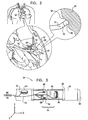
- Fig. 2 is a schematic sectional view of a chamber of a heart 22, showing distal end 30 of catheter 28 inside the heart, in accordance with an embodiment of the present invention.
- the catheter comprises an insertion tube 50, which is typically inserted into the heart percutaneously through a blood vessel, such as the vena cava or the aorta.
- An electrode 56 on a distal tip 52 of the catheter engages endocardial tissue 58. Pressure exerted by the distal tip against the endocardium deforms the endocardial tissue locally, so that electrode 56 contacts the tissue over a relatively large area.
- the electrode engages the endocardium at an angle, rather than head-on.
- Distal tip 52 therefore bends at an elastic joint 54 relative to the distal end of insertion tube 50 of the catheter. The bend facilitates optimal contact between the electrode and the endocardial tissue.
- the angle of bending and the axial displacement of the joint are proportional to the pressure exerted by tissue 58 on distal tip 52 (or equivalently, the pressure exerted by the distal tip on the tissue). Measurement of the bend angle and axial displacement thus gives an indication of this pressure.
- the pressure indication may be used by the operator of catheter 20 is ensuring that the distal tip is pressing against the endocardium firmly enough to give the desired therapeutic or diagnostic result, but not so hard as to cause undesired tissue damage.
- Fig. 3 is a schematic, sectional view of distal end 30 of catheter 28, showing details of the structure of the catheter in accordance with an embodiment of the present invention.
- Insertion tube 50 is connected to distal tip 52 by joint 54, as noted above.
- the insertion tube is covered by a flexible, insulating material 62, such as Celcon®, Teflon®, or heat-resistant polyurethane, for example.
- the area of joint 54 is covered, as well, by a flexible, insulating material, which may be the same as material 62 or may be specially adapted to permit unimpeded bending and compression of the joint. (This material is cut away in Fig.
- Distal tip 52 may be covered, at least in part, by electrode 56, which is typically made of a conductive material, such as a platinum/iridium alloy. Alternatively, other suitable materials may be used, as will be apparent to those skilled in the art. Further alternatively, for some applications, the distal tip may be made without a covering electrode. The distal tip is typically relatively rigid, by comparison with the flexible insertion tube.
- the coupling member has the form of a tubular piece of an elastic material, with a helical cut along a portion of its length.
- the coupling member may comprise a superelastic alloy, such as nickel titanium (Nitinol).
- Nitinol nickel titanium
- the helical cut causes the tubular piece to behave like a spring in response to forces exerted on distal tip 52.
- the coupling member may comprise a coil spring or any other suitable sort of resilient component with the desired flexibility and strength characteristics.
- the stiffness of coupling member 60 determines the range of relative movement between tip 52 and insertion tube 50 in response to forces exerted on the distal tip. Such forces are encountered when the distal tip is pressed against the endocardium during an ablation procedure.
- the desired pressure for good electrical contact between the distal tip and the endocardium during ablation is on the order of 20-30 grams.
- the coupling member is configured to permit axial displacement (i.e., lateral movement along the axis of catheter 28) and angular deflection of the distal tip in proportion to the pressure on the tip. Measurement of the displacement and deflection by processor 36 gives an indication of the pressure and thus helps to ensure that the correct pressure is applied during ablation.
- a joint sensing assembly comprising coils 64, 66, 68 and 70 within catheter 28, provides accurate reading of the position of distal tip 52 relative to the distal end of insertion tube 50, including axial displacement and angular deflection.
- These coils are one type of magnetic transducer that may be used in embodiments of the present invention.
- the coils in catheter 28 are divided between two subassemblies on opposite sides of joint 54:
- One subassembly comprises coil 64, which is driven by a current via a cable 74 from console 34 to generate a magnetic field.
- This field is received by a second subassembly, comprising coils 66, 68 and 70, which are located in a section of the catheter that is spaced axially apart from coil 64.
- Coils 66, 68 and 70 emit electrical signals in response to the magnetic field generated by coil 64. These signals are conveyed by cable 74 to processor 36, which processes the signals in order to measure the axial displacement and angular deflection of joint 54.
- Coils 66, 68 and 70 are fixed in catheter 28 at different radial locations.
- radial refers to coordinates relative to the catheter axis, i.e., coordinates in an X-Y plane in Fig. 3 .
- coils 66, 68 and 70 are all located in the same axial plane at different azimuthal angles about the catheter axis.
- the three coils may be spaced azimuthally 120° apart at the same radial distance from the axis.
- coils 64, 66, 68 and 70 are parallel to the catheter axis (and thus to one another, as long as joint 54 is undeflected). Consequently, coils 66, 68 and 70 will output strong signals in response to the field generated by coil 64, and the signals will vary strongly with the distances of coils 66, 68 and 70 from coil 64.
- the axis of coil 64 and/or coils 66, 68 and 70 may be angled relative to the catheter axis, as long as the coil axes have a sufficient parallel component in order to give substantial signals.
- Angular deflection of tip 52 will give rise to a differential change in the signals output by coils 66, 68 and 70, depending on the direction and magnitude of deflection, since one or two of these coils will move relatively closer to coil 64. Compressive displacement of the tip will give rise to an increase in the signals from all of coils 66, 68 and 70.
- Processor 36 analyzes the signals output by coils 66, 68 and 70 in order to measure the deflection and displacement of joint 54.
- the sum of the changes in the signals gives a measure of the compression, while the difference of the changes gives the deflection.
- the vector direction of the difference gives an indication of the bend direction.
- a suitable calibration procedure may be used to measure the precise dependence of the signals on deflection and displacement of the joint.
- coils in the sensing subassemblies may also be used, in addition to the configuration shown and described above.
- the positions of the subassemblies may be reversed, so that that field generator coil is on the proximal side of joint 54, and the sensor coils are in the distal tip.
- coils 66, 68 and 70 may be driven as field generators (using time- and/or frequency-multiplexing to distinguish the fields), while coil 64 serves as the sensor.
- the sizes and numbers of the coils in Fig. 3 are shown only by way of example, and larger or smaller numbers of coils may similarly be used, in various different positions, so long as one of the subassemblies comprises at least two coils, in different radial positions, to allow differential measurement of joint deflection.
- Prior calibration of the relation between pressure on tip 52 and movement of joint 54 may be used by processor 36 in translating the coil signals into terms of pressure.
- this pressure sensing system reads the pressure correctly regardless of whether the electrode engages the endocardium head-on or at an angle.
- the pressure reading is insensitive to temperature variations and free of drift, unlike piezoelectric sensors, for example.
- processor 36 can measure small displacements and deflections with high precision. Therefore, coupling member 60 can be made relatively stiff, and processor 36 will still be able to sense and measure accurately the pressure on tip 52. The stiffness of the coupling member makes it easier for the operator to maneuver and control the catheter.
- coils 64, 66, 68 and 70 may also be used to output signals in response to the magnetic fields generated by field generators 32, and thus serve as position sensing coils.
- Processor 36 processes these signals in order to determine the coordinates (position and orientation) of distal end 30 in the external frame of reference that is defined by the field generators.
- one or more further coils 72 may be deployed in the distal end of the catheter for this purpose.
- the position sensing coils in distal end 30 of catheter 28 enable console 34 to output both the location and orientation of the catheter in the body and the displacement and deflection of tip 52, as well as the pressure on the tip.
- a magnetic position sensing assembly and its use in sensing pressure are described above in the context of catheter-based ablation, the principles of the present invention may similarly be applied in other applications that require accurate sensing of the movement of a joint, and particularly in therapeutic and diagnostic applications that use invasive probes, both in the heart and in other organs of the body.
- the devices and techniques for position and pressure sensing that are implemented in system 20 may be applied, mutatis mutandis , in guiding and controlling the use of a catheter insertion sheath. If the position of the sheath is not properly controlled and excessive force is used in its insertion, the sheath may perforate the heart wall or vascular tissue.
- distal tip should be understood to include any sort of structure at the distal end of a probe that may be bent and/or displaced relative to the main body of the probe.
Abstract
Description
- This application is a continuation-in-part of
U.S. Patent Application 11/868,733, filed October 8, 2007 - The present invention relates generally to invasive medical devices, and specifically to methods and devices for sensing displacement of a joint in a probe, such as a catheter, that is applied to the body of a patient.
- In some diagnostic and therapeutic techniques, a catheter is inserted into a chamber of the heart and brought into contact with the inner heart wall. In such procedures, it is generally important that the distal tip of the catheter engages the endocardium with sufficient pressure to ensure good contact. Excessive pressure, however, may cause undesired damage to the heart tissue and even perforation of the heart wall.
- For example, in intracardiac radio-frequency (RF) ablation, a catheter having an electrode at its distal tip is inserted through the patient's vascular system into a chamber of the heart. The electrode is brought into contact with a site (or sites) on the endocardium, and RF energy is applied through the catheter to the electrode in order to ablate the heart tissue at the site. Proper contact between the electrode and the endocardium during ablation is necessary in order to achieve the desired therapeutic effect without excessive damage to the tissue.
- A number of patent publications describe catheters with integrated pressure sensors for sensing tissue contact. As one example,
U.S. Patent Application Publication 2007/0100332 , whose disclosure is incorporated herein by reference, describes systems and methods for assessing electrode-tissue contact for tissue ablation. An electro-mechanical sensor within the catheter shaft generates electrical signals corresponding to the amount of movement of the electrode within a distal portion of the catheter shaft. An output device receives the electrical signals for assessing a level of contact between the electrode and a tissue. - The embodiments of the present invention that are described hereinbelow provide novel apparatus and methods for sensing displacement of a joint, by generating and sensing magnetic fields using magnetic transducers, such as coils, on opposite sides of the joint. A disclosed embodiment relates specifically to the use of this sort of sensing apparatus in an invasive medical probe, in which the apparatus provides an indication of pressure exerted on the tip of the probe. The principles of the present invention, however, are similarly useful in applications of other sorts that require accurate sensing of joint displacement.
- There is therefore provided, in accordance with an embodiment of the present invention a medical probe, including an insertion tube, having a longitudinal axis and having a distal end. A distal tip is disposed at the distal end of the insertion tube and is configured to be brought into contact with a body tissue. A joint couples the distal tip to the distal end of the insertion tube. A joint sensor, contained within the probe, senses a position of the distal tip relative to the distal end of the insertion tube, the joint sensor including first and second subassemblies, which are disposed within the probe on opposite, respective sides of the joint and each include one or more magnetic transducers.
- In some embodiments, the magnetic transducers includes coils, and the first subassembly includes a first coil having a first coil axis parallel to the longitudinal axis of the insertion tube, and the second subassembly includes two or more second coils in different, respective radial locations within a section of the probe that is spaced apart axially from the first subassembly. In one embodiment, the second coils have respective second coil axes that are parallel to the longitudinal axis of the insertion tube. Additionally or alternatively, the two or more second coils include at least three second coils, which are disposed within an axial plane of the probe at different, respective azimuthal angles about the longitudinal axis.
- In a disclosed embodiment, the joint sensor is configured to generate a signal indicative of an axial displacement and an orientation of the distal tip relative to the distal end of the insertion tube. Typically one of the first and second subassemblies is coupled to be driven by an electrical current to emit at least one magnetic field, and the other of the first and second subassemblies is coupled to output one or more signals in response to the at least one magnetic field, wherein the signals are indicative of the position of the distal tip relative to the distal end of the insertion tube.
- In one embodiment, the probe includes a position sensor for sensing position coordinates of the probe relative to a frame of reference that is separate from the probe. Additionally or alternatively, the distal tip includes an electrode, which is configured to make electrical contact with the tissue.
- In some embodiments, the joint includes a resilient member, which is configured to deform in response to pressure exerted on the distal tip when the distal tip engages the tissue. The resilient member may include a tubular piece of an elastic material having a helical cut therethrough along a portion of a length of the piece.
- There is also provided, in accordance with an embodiment of the present invention, apparatus for performing a medical procedure on a body of a patient. The apparatus includes a probe, which includes an insertion tube, having a longitudinal axis and having a distal end; a distal tip, which is disposed at the distal end of the insertion tube and is configured to be brought into contact with tissue of the body; a joint, which couples the distal tip to the distal end of the insertion tube; and a joint sensor, contained within the probe, for sensing a position of the distal tip relative to the distal end of the insertion tube, the joint sensor including first and second subassemblies, which are disposed within the probe on opposite, respective sides of the joint and each include one or more magnetic transducers. A processor is coupled to apply a current to one of the first and second subassemblies, thereby causing the one of the subassemblies to generate at least one magnetic field, and is coupled to receive and process one or more signals output by the other of the first and second subassemblies responsively to the at least one magnetic field so as to detect changes in a position of the distal tip relative to the distal end of the insertion tube.
- In some embodiments, the apparatus includes a magnetic field generator, for generating a further magnetic field in a vicinity of the body, and a position sensor in the probe for generating a position signal in response to the further magnetic field, wherein the processor is coupled to receive and process the position signal in order to compute coordinates of the probe relative to a frame of reference that is separate from the probe. In a disclosed embodiment, the position sensor includes at least one of the magnetic transducers in one of the first and second subassemblies.
- There is additionally provided, in accordance with an embodiment of the present invention, apparatus for sensing movement of a joint in an assembly having a longitudinal axis passing through the joint. The apparatus includes first and second sensing subassemblies, which are disposed within the assembly on opposite, respective sides of the joint and each include one or more magnetic transducers. A processor is coupled to apply a current to one of the first and second assemblies, thereby causing the one of the assemblies to generate at least one magnetic field, and is coupled to receive and process one or more signals output by the other of the first and second assemblies responsively to the at least one magnetic field so as to detect changes in a disposition of the joint.
- Preferably, the magnetic transducers comprise coils, and the first subassembly comprises a first coil having a first coil axis parallel to the longitudinal axis of the insertion tube, and the second subassembly comprises two or more second coils in different, respective radial locations within a section of the assembly that is spaced apart axially from the first subassembly.
- Preferably, the processor is configured to detect, by processing the one or more signals, an axial compression of the joint and an angular deflection of the joint.
- Preferably, the joint comprises a resilient member, which is configured to deform in response to pressure exerted on the assembly, and the processor is configured to generate, responsively to the detected changes in the disposition, an output that is indicative of the pressure exerted on the assembly.
- There is further provided, in accordance with an embodiment of the present invention, a method for performing a medical procedure on tissue in a body of a patient. The method includes applying to the body a probe, which includes an insertion tube and a distal tip, which is coupled to a distal end of the insertion tube by a joint, and which includes a joint sensor, which is contained within the probe and includes first and second subassemblies, which are disposed within the probe on opposite, respective sides of the joint and each include one or more magnetic transducers. The probe is advanced so that the distal tip engages and applies a pressure against the tissue, so as to cause a change in a position of the distal tip relative to the distal end of the insertion tube. A current is applied to one of the first and second subassemblies, thereby causing the one of the subassemblies to generate at least one magnetic field. One or more signals output are received by the other of the first and second subassemblies responsively to the at least one magnetic field and are processed so as to detect the change in the position of the distal tip.
- In one embodiment, advancing the probe includes bringing an electrode on the distal tip into electrical contact with the tissue. The method may include applying electrical energy to the electrode so as to ablate a region of the tissue that is engaged by the distal tip, wherein the position of the distal tip relative to the distal end of the insertion tube changes in response to a pressure of the distal tip against the tissue, and wherein applying the electrical energy includes controlling application of the energy responsively to the pressure, as indicated by the position of the distal tip, so that the electrical energy is applied to the electrode when the pressure is within a desired range.
- The present invention will be more fully understood from the following detailed description of the embodiments thereof, taken together with the drawings in which:
-
-
Fig. 1 is a schematic, pictorial illustration of a catheter-based medical system, in accordance with an embodiment of the present invention; -
Fig. 2 is a schematic detail view showing the distal tip of a catheter in contact with endocardial tissue, in accordance with an embodiment of the present invention; and -
Fig. 3 is a schematic, sectional view showing details of the distal end of a catheter, in accordance with an embodiment of the present invention. - The above-mentioned
U.S. Patent Application 11/868,733 describes a catheter whose distal tip is coupled to the distal end of the catheter insertion tube by a spring-loaded joint, which deforms in response to pressure exerted on the distal tip when it engages tissue. A magnetic position sensing assembly within the probe, comprising coils on opposite sides of the joint, senses the position of the distal tip relative to the distal end of the insertion tube. Changes in this relative position are indicative of deformation of the spring and thus give an indication of the pressure. - Embodiments of the present invention that are described hereinbelow provide a new design of the sensing assembly, which facilitates more precise measurement of tip movement. The configuration of the coils in this new design permits precise sensing of very small deflections and compressions of the joint connecting the catheter tip to the insertion tube. Therefore, the pressure on the tip can be measured with enhanced accuracy, permitting the use a relatively stiffer spring in the catheter, which makes the catheter more reliable and easier to maneuver in the body.
-
Fig. 1 is a schematic, pictorial illustration of asystem 20 for cardiac catheterization, in accordance with an embodiment of the present invention.System 20 may be based, for example, on the CARTO™ system, produced by Biosense Webster Inc. (Diamond Bar, California). This system comprises an invasive probe in the form of acatheter 28 and acontrol console 34. In the embodiment described hereinbelow, it is assumed thatcatheter 28 is used in ablating endocardial tissue, as is known in the art. Alternatively, the catheter may be used, mutatis mutandis, for other therapeutic and/or diagnostic purposes in the heart or in other body organs. - An
operator 26, such as a cardiologist, insertscatheter 28 through the vascular system of a patient 24 so that adistal end 30 of the catheter enters a chamber of the patient'sheart 22. The operator advances the catheter so that the distal tip of the catheter engages endocardial tissue at a desired location or locations.Catheter 28 is typically connected by a suitable connector at its proximal end to console 34. The console may comprise a radio frequency (RF) generator, which supplies high-frequency electrical energy via the catheter for ablating tissue in the heart at the locations engaged by the distal tip. Alternatively or additionally, the catheter and system may be configured to perform other therapeutic and diagnostic procedures that are known in the art. -
Console 34 uses magnetic position sensing to determine position coordinates ofdistal end 30 ofcatheter 28 insideheart 22. For this purpose, adriver circuit 38 inconsole 34drives field generators 32 to generate magnetic fields in the vicinity of the body ofpatient 24. Typically, the field generators comprise coils, which are placed below the patient's torso at known positions external to the patient. These coils generate magnetic fields within the body in a predefined working volume that containsheart 22. A magnetic field sensor withindistal end 30 of catheter 28 (shown inFig. 3 ) generates electrical signals in response to these magnetic fields. Asignal processor 36 processes these signals in order to determine the position coordinates of the distal end, typically including both location and orientation coordinates. This method of position sensing is implemented in the above-mentioned CARTO system and is described in detail inU.S. Patents 5,391,199 ,6,690,963 ,6,484,118 ,6,239,724 ,6,618,612 and6,332,089 , inPCT Patent Publication WO 96/05768 U.S. Patent Application Publications 2002/0065455 A1 ,2003/0120150 A1 and2004/0068178 A1 , whose disclosures are all incorporated herein by reference. -
Processor 36 typically comprises a general-purpose computer, with suitable front end and interface circuits for receiving signals fromcatheter 28 and controlling the other components ofconsole 34. The processor may be programmed in software to carry out the functions that are described herein. The software may be downloaded to console 34 in electronic form, over a network, for example, or it may be provided on tangible media, such as optical, magnetic or electronic memory media. Alternatively, some or all of the functions ofprocessor 36 may be carried out by dedicated or programmable digital hardware components. Based on the signals received from the catheter and other components ofsystem 20,processor 36 drives adisplay 42 to giveoperator 26 visual feedback regarding the position ofdistal end 30 in the patient's body, as well as regarding displacement of the distal tip of the catheter, and status information and guidance regarding the procedure that is in progress. - Alternatively or additionally,
system 20 may comprise an automated mechanism for maneuvering and operatingcatheter 28 within the body ofpatient 24. Such mechanisms are typically capable of controlling both the longitudinal motion (advance/retract) of the catheter and transverse motion (deflection/steering) of the distal end of the catheter. Some mechanisms of this sort use DC magnetic fields for this purpose, for example. In such embodiments,processor 36 generates a control input for controlling the motion of the catheter based on the signals provided by the magnetic field sensor in the catheter. These signals are indicative of both the position of the distal end of the catheter and of force exerted on the distal end, as explained further hereinbelow. -
Fig. 2 is a schematic sectional view of a chamber of aheart 22, showingdistal end 30 ofcatheter 28 inside the heart, in accordance with an embodiment of the present invention. The catheter comprises aninsertion tube 50, which is typically inserted into the heart percutaneously through a blood vessel, such as the vena cava or the aorta. Anelectrode 56 on adistal tip 52 of the catheter engagesendocardial tissue 58. Pressure exerted by the distal tip against the endocardium deforms the endocardial tissue locally, so thatelectrode 56 contacts the tissue over a relatively large area. In the pictured example, the electrode engages the endocardium at an angle, rather than head-on.Distal tip 52 therefore bends at an elastic joint 54 relative to the distal end ofinsertion tube 50 of the catheter. The bend facilitates optimal contact between the electrode and the endocardial tissue. - Because of the elastic quality of joint 54, the angle of bending and the axial displacement of the joint are proportional to the pressure exerted by
tissue 58 on distal tip 52 (or equivalently, the pressure exerted by the distal tip on the tissue). Measurement of the bend angle and axial displacement thus gives an indication of this pressure. The pressure indication may be used by the operator ofcatheter 20 is ensuring that the distal tip is pressing against the endocardium firmly enough to give the desired therapeutic or diagnostic result, but not so hard as to cause undesired tissue damage. -
Fig. 3 is a schematic, sectional view ofdistal end 30 ofcatheter 28, showing details of the structure of the catheter in accordance with an embodiment of the present invention.Insertion tube 50 is connected todistal tip 52 by joint 54, as noted above. The insertion tube is covered by a flexible, insulatingmaterial 62, such as Celcon®, Teflon®, or heat-resistant polyurethane, for example. The area of joint 54 is covered, as well, by a flexible, insulating material, which may be the same asmaterial 62 or may be specially adapted to permit unimpeded bending and compression of the joint. (This material is cut away inFig. 3 in order to expose the internal structure of the catheter.)Distal tip 52 may be covered, at least in part, byelectrode 56, which is typically made of a conductive material, such as a platinum/iridium alloy. Alternatively, other suitable materials may be used, as will be apparent to those skilled in the art. Further alternatively, for some applications, the distal tip may be made without a covering electrode. The distal tip is typically relatively rigid, by comparison with the flexible insertion tube. - Joint 54 comprises a
resilient coupling member 60. In this embodiment, the coupling member has the form of a tubular piece of an elastic material, with a helical cut along a portion of its length. For example, the coupling member may comprise a superelastic alloy, such as nickel titanium (Nitinol). The helical cut causes the tubular piece to behave like a spring in response to forces exerted ondistal tip 52. Further details regarding the fabrication and characteristics of this sort of coupling member are presented inU.S. Patent Application 12/134,592, filed June 6, 2008 - The stiffness of
coupling member 60 determines the range of relative movement betweentip 52 andinsertion tube 50 in response to forces exerted on the distal tip. Such forces are encountered when the distal tip is pressed against the endocardium during an ablation procedure. The desired pressure for good electrical contact between the distal tip and the endocardium during ablation is on the order of 20-30 grams. The coupling member is configured to permit axial displacement (i.e., lateral movement along the axis of catheter 28) and angular deflection of the distal tip in proportion to the pressure on the tip. Measurement of the displacement and deflection byprocessor 36 gives an indication of the pressure and thus helps to ensure that the correct pressure is applied during ablation. - A joint sensing assembly, comprising coils 64, 66, 68 and 70 within
catheter 28, provides accurate reading of the position ofdistal tip 52 relative to the distal end ofinsertion tube 50, including axial displacement and angular deflection. These coils are one type of magnetic transducer that may be used in embodiments of the present invention. A "magnetic transducer," in the context of the present patent application and in the claims, means a device that generates a magnetic field in response to an applied electrical current and/or outputs an electrical signal in response to an applied magnetic field. Although the embodiments described herein use coils as magnetic transducers, other types of magnetic transducers may be used in alternative embodiments, as will be apparent to those skilled in the art. - The coils in
catheter 28 are divided between two subassemblies on opposite sides of joint 54: One subassembly comprisescoil 64, which is driven by a current via acable 74 fromconsole 34 to generate a magnetic field. This field is received by a second subassembly, comprising coils 66, 68 and 70, which are located in a section of the catheter that is spaced axially apart fromcoil 64. (The term "axial," as used in the context of the present patent application and in the claims, refers to the direction of the longitudinal axis ofdistal end 30 ofcatheter 28, which is identified as the Z-direction inFig. 3 . An axial plane is a plane perpendicular to this longitudinal axis, and an axial section is a portion of the catheter contained between two axial planes.)Coils coil 64. These signals are conveyed bycable 74 toprocessor 36, which processes the signals in order to measure the axial displacement and angular deflection of joint 54. -
Coils catheter 28 at different radial locations. (The term "radial" refers to coordinates relative to the catheter axis, i.e., coordinates in an X-Y plane inFig. 3 .) Specifically, in this embodiment, coils 66, 68 and 70 are all located in the same axial plane at different azimuthal angles about the catheter axis. For example, the three coils may be spaced azimuthally 120° apart at the same radial distance from the axis. - The axes of
coils coil 64, and the signals will vary strongly with the distances ofcoils coil 64. (Alternatively, the axis ofcoil 64 and/or coils 66, 68 and 70 may be angled relative to the catheter axis, as long as the coil axes have a sufficient parallel component in order to give substantial signals.) Angular deflection oftip 52 will give rise to a differential change in the signals output bycoils coil 64. Compressive displacement of the tip will give rise to an increase in the signals from all ofcoils -
Processor 36 analyzes the signals output bycoils - Various other configurations of the coils in the sensing subassemblies may also be used, in addition to the configuration shown and described above. For example, the positions of the subassemblies may be reversed, so that that field generator coil is on the proximal side of joint 54, and the sensor coils are in the distal tip. As another alternative, coils 66, 68 and 70 may be driven as field generators (using time- and/or frequency-multiplexing to distinguish the fields), while
coil 64 serves as the sensor. The sizes and numbers of the coils inFig. 3 are shown only by way of example, and larger or smaller numbers of coils may similarly be used, in various different positions, so long as one of the subassemblies comprises at least two coils, in different radial positions, to allow differential measurement of joint deflection. - Prior calibration of the relation between pressure on
tip 52 and movement of joint 54 may be used byprocessor 36 in translating the coil signals into terms of pressure. By virtue of the combined sensing of displacement and deflection, this pressure sensing system reads the pressure correctly regardless of whether the electrode engages the endocardium head-on or at an angle. The pressure reading is insensitive to temperature variations and free of drift, unlike piezoelectric sensors, for example. Because of the high sensitivity to joint motion that is afforded by the arrangement ofcoils Fig. 3 ,processor 36 can measure small displacements and deflections with high precision. Therefore,coupling member 60 can be made relatively stiff, andprocessor 36 will still be able to sense and measure accurately the pressure ontip 52. The stiffness of the coupling member makes it easier for the operator to maneuver and control the catheter. - One or more of
coils field generators 32, and thus serve as position sensing coils.Processor 36 processes these signals in order to determine the coordinates (position and orientation) ofdistal end 30 in the external frame of reference that is defined by the field generators. Additionally or alternatively, one or more further coils 72 (or other magnetic sensors) may be deployed in the distal end of the catheter for this purpose. The position sensing coils indistal end 30 ofcatheter 28 enableconsole 34 to output both the location and orientation of the catheter in the body and the displacement and deflection oftip 52, as well as the pressure on the tip. - Although the operation of a magnetic position sensing assembly and its use in sensing pressure are described above in the context of catheter-based ablation, the principles of the present invention may similarly be applied in other applications that require accurate sensing of the movement of a joint, and particularly in therapeutic and diagnostic applications that use invasive probes, both in the heart and in other organs of the body. As one example, the devices and techniques for position and pressure sensing that are implemented in
system 20 may be applied, mutatis mutandis, in guiding and controlling the use of a catheter insertion sheath. If the position of the sheath is not properly controlled and excessive force is used in its insertion, the sheath may perforate the heart wall or vascular tissue. This eventuality can be avoided by sensing the position of and pressure on the distal tip of the sheath. In this regard, the term "distal tip" as used herein should be understood to include any sort of structure at the distal end of a probe that may be bent and/or displaced relative to the main body of the probe. - It will thus be appreciated that the embodiments described above are cited by way of example, and that the present invention is not limited to what has been particularly shown and described hereinabove. Rather, the scope of the present invention includes both combinations and subcombinations of the various features described hereinabove, as well as variations and modifications thereof which would occur to persons skilled in the art upon reading the foregoing description and which are not disclosed in the prior art.
Claims (24)
- A medical probe, comprising:an insertion tube, having a longitudinal axis and having a distal end;a distal tip, which is disposed at the distal end of the insertion tube and is configured to be brought into contact with a body tissue;a joint, which couples the distal tip to the distal end of the insertion tube; anda joint sensor, contained within the probe, for sensing a position of the distal tip relative to the distal end of the insertion tube, the joint sensor comprising first and second subassemblies, which are disposed within the probe on opposite, respective sides of the joint and each comprise one or more magnetic transducers.
- The probe according to claim 1, wherein the magnetic transducers comprises coils, and wherein the first subassembly comprises a first coil having a first coil axis parallel to the longitudinal axis of the insertion tube, and wherein the second subassembly comprises two or more second coils in different, respective radial locations within a section of the probe that is spaced apart axially from the first subassembly.
- The probe according to claim 2, wherein the second coils have respective second coil axes that are parallel to the longitudinal axis of the insertion tube.
- The probe according to claim 2, wherein the two or more second coils comprise at least three second coils.
- The probe according to claim 4, wherein the at least three second coils are disposed within an axial plane of the probe at different, respective azimuthal angles about the longitudinal axis.
- The probe according to claim 1, wherein the joint sensor is configured to generate a signal indicative of an axial displacement and an orientation of the distal tip relative to the distal end of the insertion tube.
- The probe according to claim 6, wherein one of the first and second subassemblies is coupled to be driven by an electrical current to emit at least one magnetic field, and the other of the first and second subassemblies is coupled to output one or more signals in response to the at least one magnetic field, wherein the signals are indicative of the position of the distal tip relative to the distal end of the insertion tube.
- The probe according to claim 1, and comprising a position sensor for sensing position coordinates of the probe relative to a frame of reference that is separate from the probe.
- The probe according to claim 1, wherein the distal tip comprises an electrode, which is configured to make electrical contact with the tissue.
- The probe according to claim 1, wherein the joint comprises a resilient member, which is configured to deform in response to pressure exerted on the distal tip when the distal tip engages the tissue.
- The probe according to claim 10, wherein the resilient member comprises a tubular piece of an elastic material having a helical cut therethrough along a portion of a length of the piece.
- Apparatus for performing a medical procedure on a body of a patient, the apparatus comprising:a probe according to claim 1 or claim 2 or claim 10; anda processor, which is coupled to apply a current to one of the first and second subassemblies, thereby causing the one of the subassemblies to generate at least one magnetic field, and which is coupled to receive and process one or more signals output by the other of the first and second subassemblies responsively to the at least one magnetic field so as to detect changes in a position of the distal tip relative to the distal end of the insertion tube.
- The apparatus according to claim 12, wherein the changes in the position of the distal tip detected by the processor comprise an axial displacement of the distal tip and a deflection of the distal tip relative to the distal end of the insertion tube.
- The apparatus according to claim 12 when dependent upon claim 10, wherein the processor is configured to generate, responsively to the detected changes in the position, an output that is indicative of the pressure exerted on the distal tip.
- The apparatus according to claim 12, and comprising a magnetic field generator, for generating a further magnetic field in a vicinity of the body, and a position sensor in the probe for generating a position signal in response to the further magnetic field, wherein the processor is coupled to receive and process the position signal in order to compute coordinates of the probe relative to a frame of reference that is separate from the probe.
- The apparatus according to claim 15, wherein the position sensor comprises at least one of the magnetic transducers in one of the first and second subassemblies.
- A method for performing a medical procedure on tissue in a body of a patient, the method comprising:applying to the body a probe, which comprises an insertion tube and a distal tip, which is coupled to a distal end of the insertion tube by a joint, and which comprises a joint sensor, which is contained within the probe and comprises first and second subassemblies, which are disposed within the probe on opposite, respective sides of the joint and each comprise one or more magnetic transducers;advancing the probe so that the distal tip engages and applies a pressure against the tissue, so as to cause a change in a position of the distal tip relative to the distal end of the insertion tube;applying a current to one of the first and second subassemblies, thereby causing the one of the subassemblies to generate at least one magnetic field; andreceiving and processing one or more signals output by the other of the first and second subassemblies responsively to the at least one magnetic field so as to detect the change in the position of the distal tip.
- The method according to claim 17, wherein the magnetic transducers comprise coils, and wherein the first subassembly comprises a first coil having a first coil axis parallel to a longitudinal axis of the insertion tube, and wherein the second subassembly comprises two or more second coils in different, respective radial locations within a section of the probe that is spaced apart axially from the first subassembly.
- The method according to claim 17, wherein processing the one or more signals comprises detecting an axial displacement and an orientation of the distal tip relative to the distal end of the insertion tube.
- The method according to claim 17, wherein the joint comprises a resilient member, which is configured to deform in response to the pressure on the distal tip, and wherein processing the one or more signals comprises generating, responsively to the detected change in the position, an indication of the pressure exerted on the distal tip.
- The method according to claim 17, and comprising generating a further magnetic field in a vicinity of the body, and sensing a position signal output by one of the first and second subassemblies in response to the further magnetic field in order to compute coordinates of the probe relative to a frame of reference that is separate from the probe.
- The method according to claim 17, wherein advancing the probe comprises bringing an electrode on the distal tip into electrical contact with the tissue.
- The method according to claim 22, and comprising applying electrical energy to the electrode so as to ablate a region of the tissue that is engaged by the distal tip.
- The method according to claim 23, wherein the position of the distal tip relative to the distal end of the insertion tube changes in response to a pressure of the distal tip against the tissue, and wherein applying the electrical energy comprises controlling application of the energy responsively to the pressure, as indicated by the position of the distal tip, so that the electrical energy is applied to the electrode when the pressure is within a desired range.
Applications Claiming Priority (1)
| Application Number | Priority Date | Filing Date | Title |
|---|---|---|---|
| US12/327,226 US8535308B2 (en) | 2007-10-08 | 2008-12-03 | High-sensitivity pressure-sensing probe |
Publications (2)
| Publication Number | Publication Date |
|---|---|
| EP2196143A1 true EP2196143A1 (en) | 2010-06-16 |
| EP2196143B1 EP2196143B1 (en) | 2012-08-08 |
Family
ID=42026268
Family Applications (1)
| Application Number | Title | Priority Date | Filing Date |
|---|---|---|---|
| EP09252721A Active EP2196143B1 (en) | 2008-12-03 | 2009-12-02 | High-sensitivity pressure-sensing probe |
Country Status (10)
| Country | Link |
|---|---|
| US (2) | US8535308B2 (en) |
| EP (1) | EP2196143B1 (en) |
| JP (1) | JP5566672B2 (en) |
| CN (1) | CN101780303B (en) |
| AU (1) | AU2009243426B2 (en) |
| CA (1) | CA2686886C (en) |
| DK (1) | DK2196143T3 (en) |
| ES (1) | ES2392607T3 (en) |
| IL (2) | IL229292A (en) |
| RU (1) | RU2517599C2 (en) |
Cited By (16)
| Publication number | Priority date | Publication date | Assignee | Title |
|---|---|---|---|---|
| CN102327118A (en) * | 2010-06-30 | 2012-01-25 | 韦伯斯特生物官能(以色列)有限公司 | Pressure sensing for a multi-arm catheter |
| EP2505227A1 (en) * | 2011-03-30 | 2012-10-03 | Biosense Webster (Israel), Ltd. | Force measurement for large bend angles of catheter |
| US8731859B2 (en) | 2010-10-07 | 2014-05-20 | Biosense Webster (Israel) Ltd. | Calibration system for a force-sensing catheter |
| EP2749240A2 (en) * | 2012-12-31 | 2014-07-02 | Jeffrey L. Clark | Catheter with serially connected sensing structures and methods of calibration and detection |
| US8784413B2 (en) | 2007-10-08 | 2014-07-22 | Biosense Webster (Israel) Ltd. | Catheter with pressure sensing |
| US8798952B2 (en) | 2010-06-10 | 2014-08-05 | Biosense Webster (Israel) Ltd. | Weight-based calibration system for a pressure sensitive catheter |
| US8852130B2 (en) | 2009-12-28 | 2014-10-07 | Biosense Webster (Israel), Ltd. | Catheter with strain gauge sensor |
| US8900229B2 (en) | 2007-10-08 | 2014-12-02 | Biosense Webster (Israel) Ltd. | High-sensitivity pressure-sensing probe |
| US8979772B2 (en) | 2010-11-03 | 2015-03-17 | Biosense Webster (Israel), Ltd. | Zero-drift detection and correction in contact force measurements |
| US8990039B2 (en) | 2009-12-23 | 2015-03-24 | Biosense Webster (Israel) Ltd. | Calibration system for a pressure-sensitive catheter |
| US9101734B2 (en) | 2008-09-09 | 2015-08-11 | Biosense Webster, Inc. | Force-sensing catheter with bonded center strut |
| US9204820B2 (en) | 2012-12-31 | 2015-12-08 | Biosense Webster (Israel) Ltd. | Catheter with combined position and pressure sensing structures |
| US9326700B2 (en) | 2008-12-23 | 2016-05-03 | Biosense Webster (Israel) Ltd. | Catheter display showing tip angle and pressure |
| US9345533B2 (en) | 2008-06-06 | 2016-05-24 | Biosense Webster, Inc. | Catheter with bendable tip |
| US9687289B2 (en) | 2012-01-04 | 2017-06-27 | Biosense Webster (Israel) Ltd. | Contact assessment based on phase measurement |
| US10688278B2 (en) | 2009-11-30 | 2020-06-23 | Biosense Webster (Israel), Ltd. | Catheter with pressure measuring tip |
Families Citing this family (179)
| Publication number | Priority date | Publication date | Assignee | Title |
|---|---|---|---|---|
| US10835307B2 (en) * | 2001-06-12 | 2020-11-17 | Ethicon Llc | Modular battery powered handheld surgical instrument containing elongated multi-layered shaft |
| US7455666B2 (en) | 2001-07-13 | 2008-11-25 | Board Of Regents, The University Of Texas System | Methods and apparatuses for navigating the subarachnoid space |
| US8075498B2 (en) | 2005-03-04 | 2011-12-13 | Endosense Sa | Medical apparatus system having optical fiber load sensing capability |
| US8894589B2 (en) * | 2005-08-01 | 2014-11-25 | Endosense Sa | Medical apparatus system having optical fiber load sensing capability |
| US8567265B2 (en) * | 2006-06-09 | 2013-10-29 | Endosense, SA | Triaxial fiber optic force sensing catheter |
| US8622935B1 (en) | 2007-05-25 | 2014-01-07 | Endosense Sa | Elongated surgical manipulator with body position and distal force sensing |
| US9089360B2 (en) | 2008-08-06 | 2015-07-28 | Ethicon Endo-Surgery, Inc. | Devices and techniques for cutting and coagulating tissue |
| US8600472B2 (en) * | 2008-12-30 | 2013-12-03 | Biosense Webster (Israel), Ltd. | Dual-purpose lasso catheter with irrigation using circumferentially arranged ring bump electrodes |
| US8475450B2 (en) * | 2008-12-30 | 2013-07-02 | Biosense Webster, Inc. | Dual-purpose lasso catheter with irrigation |
| CA2703347C (en) * | 2009-05-08 | 2016-10-04 | Endosense Sa | Method and apparatus for controlling lesion size in catheter-based ablation treatment |
| US9393068B1 (en) * | 2009-05-08 | 2016-07-19 | St. Jude Medical International Holding S.À R.L. | Method for predicting the probability of steam pop in RF ablation therapy |
| US8663220B2 (en) | 2009-07-15 | 2014-03-04 | Ethicon Endo-Surgery, Inc. | Ultrasonic surgical instruments |
| DE102009034249A1 (en) * | 2009-07-22 | 2011-03-24 | Siemens Aktiengesellschaft | A method and apparatus for controlling ablation energy to perform an electrophysiology catheter application |
| WO2011044387A2 (en) | 2009-10-07 | 2011-04-14 | The Board Of Regents Of The University Of Texas System | Pressure-sensing medical devices, systems and methods, and methods of forming medical devices |
| US11090104B2 (en) | 2009-10-09 | 2021-08-17 | Cilag Gmbh International | Surgical generator for ultrasonic and electrosurgical devices |
| US10624553B2 (en) | 2009-12-08 | 2020-04-21 | Biosense Webster (Israel), Ltd. | Probe data mapping using contact information |
| US8920415B2 (en) * | 2009-12-16 | 2014-12-30 | Biosense Webster (Israel) Ltd. | Catheter with helical electrode |
| AU2015203487B2 (en) * | 2009-12-23 | 2017-08-24 | Biosense Webster (Israel), Ltd. | Calibration system for a pressure-sensitive catheter |
| US8374819B2 (en) * | 2009-12-23 | 2013-02-12 | Biosense Webster (Israel), Ltd. | Actuator-based calibration system for a pressure-sensitive catheter |
| US9962217B2 (en) | 2009-12-23 | 2018-05-08 | Biosense Webster (Israel) Ltd. | Estimation and mapping of ablation volume |
| US8926604B2 (en) * | 2009-12-23 | 2015-01-06 | Biosense Webster (Israel) Ltd. | Estimation and mapping of ablation volume |
| AU2015202549B2 (en) * | 2009-12-28 | 2017-03-02 | Biosense Webster (Israel), Ltd. | Catheter with strain gauge sensor |
| US8608735B2 (en) * | 2009-12-30 | 2013-12-17 | Biosense Webster (Israel) Ltd. | Catheter with arcuate end section |
| US8374670B2 (en) * | 2010-01-22 | 2013-02-12 | Biosense Webster, Inc. | Catheter having a force sensing distal tip |
| US8469981B2 (en) | 2010-02-11 | 2013-06-25 | Ethicon Endo-Surgery, Inc. | Rotatable cutting implement arrangements for ultrasonic surgical instruments |
| US8380276B2 (en) | 2010-08-16 | 2013-02-19 | Biosense Webster, Inc. | Catheter with thin film pressure sensing distal tip |
| US8532738B2 (en) | 2010-11-04 | 2013-09-10 | Biosense Webster (Israel), Ltd. | Visualization of catheter-tissue contact by map distortion |
| US20120123276A1 (en) * | 2010-11-16 | 2012-05-17 | Assaf Govari | Catheter with optical contact sensing |
| WO2012069649A1 (en) * | 2010-11-25 | 2012-05-31 | Sapiens Steering Brain Stimulation B.V. | Medical probe and a method of providing a medical probe |
| US8315696B2 (en) | 2010-12-09 | 2012-11-20 | Biosense Webster (Israel), Ltd. | Identifying critical CFAE sites using contact measurement |
| US10307205B2 (en) * | 2010-12-10 | 2019-06-04 | Biosense Webster (Israel) Ltd. | System and method for detection of metal disturbance based on orthogonal field components |
| US9211094B2 (en) * | 2010-12-10 | 2015-12-15 | Biosense Webster (Israel), Ltd. | System and method for detection of metal disturbance based on contact force measurement |
| US9044244B2 (en) * | 2010-12-10 | 2015-06-02 | Biosense Webster (Israel), Ltd. | System and method for detection of metal disturbance based on mutual inductance measurement |
| US9308041B2 (en) * | 2010-12-22 | 2016-04-12 | Biosense Webster (Israel) Ltd. | Lasso catheter with rotating ultrasound transducer |
| JP6027024B2 (en) | 2010-12-27 | 2016-11-16 | セント・ジュード・メディカル・ルクセンブルク・ホールディング・エスエーアールエル | Prediction of atrial wall electrical reconnection based on contact force measured during RF ablation |
| US8792962B2 (en) * | 2010-12-30 | 2014-07-29 | Biosense Webster, Inc. | Catheter with single axial sensors |
| JP6177230B2 (en) | 2011-04-14 | 2017-08-09 | セント・ジュード・メディカル・インターナショナル・ホールディング・エスエーアールエルSt. Jude Medical International Holding S.a,r.l. | Small force sensor for catheter |
| ITTO20110394A1 (en) * | 2011-05-05 | 2012-11-06 | Univ Pisa | CATHETER EQUIPPED WITH ELECTROMAGNETIC POSITION SENSORS, AND LOCALIZATION SYSTEM FOR CATHETER AND WIRE GUIDES |
| US8523787B2 (en) | 2011-06-03 | 2013-09-03 | Biosense Webster (Israel), Ltd. | Detection of tenting |
| US9220433B2 (en) | 2011-06-30 | 2015-12-29 | Biosense Webster (Israel), Ltd. | Catheter with variable arcuate distal section |
| US9662169B2 (en) | 2011-07-30 | 2017-05-30 | Biosense Webster (Israel) Ltd. | Catheter with flow balancing valve |
| US8900228B2 (en) * | 2011-09-01 | 2014-12-02 | Biosense Webster (Israel) Ltd. | Catheter adapted for direct tissue contact and pressure sensing |
| US10201385B2 (en) | 2011-09-01 | 2019-02-12 | Biosense Webster (Israel) Ltd. | Catheter adapted for direct tissue contact |
| US9014789B2 (en) | 2011-09-22 | 2015-04-21 | The George Washington University | Systems and methods for visualizing ablated tissue |
| WO2013044182A1 (en) | 2011-09-22 | 2013-03-28 | The George Washington University | Systems and methods for visualizing ablated tissue |
| US10791950B2 (en) | 2011-09-30 | 2020-10-06 | Biosense Webster (Israel) Ltd. | In-vivo calibration of contact force-sensing catheters using auto zero zones |
| EP2586363A1 (en) | 2011-10-24 | 2013-05-01 | VascoMed GmbH | Catheter and catheter system |
| US9050105B2 (en) * | 2012-03-20 | 2015-06-09 | Biosense Webster (Israel) Ltd. | Catheter with multiple irrigated electrodes and a force sensor |
| US9439668B2 (en) | 2012-04-09 | 2016-09-13 | Ethicon Endo-Surgery, Llc | Switch arrangements for ultrasonic surgical instruments |
| US20130294755A1 (en) * | 2012-05-03 | 2013-11-07 | United Video Properties, Inc. | Systems and methods for preventing access to a media asset segment during a fast-access playback operation |
| US20130303886A1 (en) * | 2012-05-09 | 2013-11-14 | Doron Moshe Ludwin | Locating a catheter sheath end point |
| US9226710B2 (en) | 2012-06-25 | 2016-01-05 | Biosense Webster (Israel) Ltd. | Wireless catheter with base wireless transceiver |
| US20140005705A1 (en) | 2012-06-29 | 2014-01-02 | Ethicon Endo-Surgery, Inc. | Surgical instruments with articulating shafts |
| US9393037B2 (en) | 2012-06-29 | 2016-07-19 | Ethicon Endo-Surgery, Llc | Surgical instruments with articulating shafts |
| US9408622B2 (en) | 2012-06-29 | 2016-08-09 | Ethicon Endo-Surgery, Llc | Surgical instruments with articulating shafts |
| US9326788B2 (en) | 2012-06-29 | 2016-05-03 | Ethicon Endo-Surgery, Llc | Lockout mechanism for use with robotic electrosurgical device |
| US9351754B2 (en) | 2012-06-29 | 2016-05-31 | Ethicon Endo-Surgery, Llc | Ultrasonic surgical instruments with distally positioned jaw assemblies |
| US9198714B2 (en) | 2012-06-29 | 2015-12-01 | Ethicon Endo-Surgery, Inc. | Haptic feedback devices for surgical robot |
| US9226767B2 (en) | 2012-06-29 | 2016-01-05 | Ethicon Endo-Surgery, Inc. | Closed feedback control for electrosurgical device |
| US9095367B2 (en) | 2012-10-22 | 2015-08-04 | Ethicon Endo-Surgery, Inc. | Flexible harmonic waveguides/blades for surgical instruments |
| US20140135804A1 (en) | 2012-11-15 | 2014-05-15 | Ethicon Endo-Surgery, Inc. | Ultrasonic and electrosurgical devices |
| US20140142438A1 (en) | 2012-11-19 | 2014-05-22 | Biosense Webster (Israel), Ltd. | Using location and force measurements to estimate tissue thickness |
| US20140160004A1 (en) | 2012-12-11 | 2014-06-12 | Biosense Webster (Israel), Ltd. | Use of physician eye tracking during a procedure |
| US9445725B2 (en) | 2012-12-17 | 2016-09-20 | Biosense Webster (Israel) Ltd. | Irrigated catheter tip with temperature sensor array |
| US20140171936A1 (en) | 2012-12-17 | 2014-06-19 | Biosense Webster (Israel) Ltd. | Irrigated catheter tip with temperature sensor and optic fiber arrays |
| US9295430B2 (en) | 2013-02-07 | 2016-03-29 | Biosense Webster (Israel), Ltd. | Operator controlled mixed modality feedback |
| US9775578B2 (en) | 2013-08-12 | 2017-10-03 | Biosense Webster (Israel) Ltd. | Unmapped region visualization |
| US10684986B2 (en) | 2013-08-28 | 2020-06-16 | Biosense Webster (Israel) Ltd. | Double buffering with atomic transactions for the persistent storage of real-time data flows |
| US9743991B2 (en) | 2013-10-21 | 2017-08-29 | Biosense Webster (Israel) Ltd. | Real-time estimation of tissue perforation risk during minimally invasive medical procedure |
| US10682175B2 (en) | 2013-11-06 | 2020-06-16 | Biosense Webster (Israel) Ltd. | Using catheter position and temperature measurement to detect movement from ablation point |
| WO2015069887A1 (en) | 2013-11-07 | 2015-05-14 | St. Jude Medical, Cardiology Division, Inc. | Medical device with contact force sensing tip |
| EP3071095A4 (en) | 2013-11-20 | 2017-07-26 | The George Washington University | Systems and methods for hyperspectral analysis of cardiac tissue |
| US10568686B2 (en) * | 2013-11-21 | 2020-02-25 | Biosense Webster (Israel) Ltd. | Multi-electrode balloon catheter with circumferential and point electrodes |
| US9572535B2 (en) | 2013-12-05 | 2017-02-21 | Biosense Webster (Israel) Ltd. | Dynamic mapping point filtering using a pre-acquired image |
| WO2015089173A1 (en) * | 2013-12-12 | 2015-06-18 | St. Jude Medical, Cardiology Division, Inc. | Medical device with contact force sensing tip |
| GB2521228A (en) | 2013-12-16 | 2015-06-17 | Ethicon Endo Surgery Inc | Medical device |
| US9795436B2 (en) | 2014-01-07 | 2017-10-24 | Ethicon Llc | Harvesting energy from a surgical generator |
| US9498147B2 (en) | 2014-01-30 | 2016-11-22 | Biosense Webster (Israel) Ltd. | Enhanced ECG chart presentation |
| JP2017506969A (en) * | 2014-03-12 | 2017-03-16 | コーニンクレッカ フィリップス エヌ ヴェKoninklijke Philips N.V. | Tactile feedback system and method for transesophageal echocardiographic ultrasound transducer probe |
| US9554854B2 (en) | 2014-03-18 | 2017-01-31 | Ethicon Endo-Surgery, Llc | Detecting short circuits in electrosurgical medical devices |
| US10092310B2 (en) | 2014-03-27 | 2018-10-09 | Ethicon Llc | Electrosurgical devices |
| CN103877664B (en) * | 2014-03-28 | 2016-03-23 | 上海凯旦医疗科技有限公司 | There is the intravascular intervention sense of touch probe of touch range and azimuth information feedback |
| US9737355B2 (en) | 2014-03-31 | 2017-08-22 | Ethicon Llc | Controlling impedance rise in electrosurgical medical devices |
| US9364285B2 (en) | 2014-04-01 | 2016-06-14 | Biosense Webster (Israel) Ltd. | Sealed two-way magnetic manifold |
| US9913680B2 (en) | 2014-04-15 | 2018-03-13 | Ethicon Llc | Software algorithms for electrosurgical instruments |
| US9784922B2 (en) | 2014-07-18 | 2017-10-10 | Biosense Webster (Israel) Ltd | Electro-optical connector with hot electrical contact protection |
| US10285724B2 (en) | 2014-07-31 | 2019-05-14 | Ethicon Llc | Actuation mechanisms and load adjustment assemblies for surgical instruments |
| US10582993B2 (en) * | 2014-08-13 | 2020-03-10 | Cosm Medical | Smart surgical spacer for tissue-implant interface |
| AU2015343258B2 (en) | 2014-11-03 | 2020-07-16 | 460Medical, Inc. | Systems and methods for lesion assessment |
| KR102612185B1 (en) | 2014-11-03 | 2023-12-08 | 460메디컬, 인크. | Systems and methods for assessment of contact quality |
| US10245095B2 (en) | 2015-02-06 | 2019-04-02 | Ethicon Llc | Electrosurgical instrument with rotation and articulation mechanisms |
| CN104887309B (en) * | 2015-06-26 | 2017-07-04 | 胡万宁 | Magnetic orientation microwave melt needle |
| US10034704B2 (en) | 2015-06-30 | 2018-07-31 | Ethicon Llc | Surgical instrument with user adaptable algorithms |
| US11051873B2 (en) | 2015-06-30 | 2021-07-06 | Cilag Gmbh International | Surgical system with user adaptable techniques employing multiple energy modalities based on tissue parameters |
| US10898256B2 (en) | 2015-06-30 | 2021-01-26 | Ethicon Llc | Surgical system with user adaptable techniques based on tissue impedance |
| US11129669B2 (en) | 2015-06-30 | 2021-09-28 | Cilag Gmbh International | Surgical system with user adaptable techniques based on tissue type |
| US11141213B2 (en) | 2015-06-30 | 2021-10-12 | Cilag Gmbh International | Surgical instrument with user adaptable techniques |
| WO2017010244A1 (en) * | 2015-07-16 | 2017-01-19 | オリンパス株式会社 | Endoscope system, endoscope apparatus, and insertion shape calculation method |
| US10779904B2 (en) | 2015-07-19 | 2020-09-22 | 460Medical, Inc. | Systems and methods for lesion formation and assessment |
| US10682176B2 (en) | 2015-08-25 | 2020-06-16 | Biosense Webster (Israel) Ltd. | System and method for controlling catheter power based on contact force |
| US20170065353A1 (en) | 2015-09-04 | 2017-03-09 | Biosense Webster (Israel) Ltd. | Identifying and presenting suspected map shifts |
| US11033201B2 (en) | 2015-09-04 | 2021-06-15 | Biosense Webster (Israel) Ltd. | Inconsistent field-based patch location coordinate correction |
| US10687884B2 (en) | 2015-09-30 | 2020-06-23 | Ethicon Llc | Circuits for supplying isolated direct current (DC) voltage to surgical instruments |
| CN105266763B (en) * | 2015-10-13 | 2018-10-26 | 翟敏 | A kind of probe |
| US10595930B2 (en) | 2015-10-16 | 2020-03-24 | Ethicon Llc | Electrode wiping surgical device |
| US10383543B2 (en) * | 2015-11-11 | 2019-08-20 | Biosense Webster (Israel) Ltd. | Symmetric short contact force sensor with four coils |
| US20170188905A1 (en) | 2015-12-30 | 2017-07-06 | Dexcom, Inc. | Biointerface layer for analyte sensors |
| CN108430368B (en) | 2016-01-07 | 2022-05-31 | 圣犹达医疗用品国际控股有限公司 | Medical device with multi-core optical fiber for optical sensing |
| US10709469B2 (en) | 2016-01-15 | 2020-07-14 | Ethicon Llc | Modular battery powered handheld surgical instrument with energy conservation techniques |
| US11229471B2 (en) | 2016-01-15 | 2022-01-25 | Cilag Gmbh International | Modular battery powered handheld surgical instrument with selective application of energy based on tissue characterization |
| US11129670B2 (en) | 2016-01-15 | 2021-09-28 | Cilag Gmbh International | Modular battery powered handheld surgical instrument with selective application of energy based on button displacement, intensity, or local tissue characterization |
| EP3411113B1 (en) | 2016-02-04 | 2019-11-27 | Cardiac Pacemakers, Inc. | Delivery system with force sensor for leadless cardiac device |
| US10555769B2 (en) | 2016-02-22 | 2020-02-11 | Ethicon Llc | Flexible circuits for electrosurgical instrument |
| WO2017155131A1 (en) * | 2016-03-08 | 2017-09-14 | (의료)길의료재단 | Endoscopic instrument having sensor unit and measurement unit and system comprising same |
| US10456193B2 (en) | 2016-05-03 | 2019-10-29 | Ethicon Llc | Medical device with a bilateral jaw configuration for nerve stimulation |
| US10405800B2 (en) * | 2016-07-13 | 2019-09-10 | Capsule Technologies, Inc. | Methods, systems, and apparatuses for detecting activation of an electronic device |
| US10376305B2 (en) | 2016-08-05 | 2019-08-13 | Ethicon Llc | Methods and systems for advanced harmonic energy |
| CN107789051A (en) * | 2016-08-30 | 2018-03-13 | 四川锦江电子科技有限公司 | A kind of catheter pressure detection method, and corresponding conduit |
| US20180125576A1 (en) | 2016-11-09 | 2018-05-10 | Biosense Webster (Israel) Ltd. | Multi-electrode catheter for preventing physiological fluid flow restriction |
| US11266430B2 (en) | 2016-11-29 | 2022-03-08 | Cilag Gmbh International | End effector control and calibration |
| CN108143481A (en) * | 2016-12-02 | 2018-06-12 | 四川锦江电子科技有限公司 | A kind of ablation catheter and the ablating device for including this conduit |
| US10888379B2 (en) | 2017-01-25 | 2021-01-12 | Biosense Webster (Israel) Ltd. | Analyzing and mapping ECG signals and determining ablation points to eliminate brugada syndrome |
| US10952793B2 (en) | 2017-01-25 | 2021-03-23 | Biosense Webster (Israel) Ltd. | Method and system for eliminating a broad range of cardiac conditions by analyzing intracardiac signals providing a detailed map and determining potential ablation points |
| US10893819B2 (en) | 2017-01-25 | 2021-01-19 | Biosense Webster (Israel) Ltd. | Analyzing and mapping ECG signals and determining ablation points to eliminate Brugada syndrome |
| CN108720920B (en) * | 2017-04-24 | 2019-07-09 | 四川锦江电子科技有限公司 | With the ablation catheter with tissue contact pressure detection function |
| US11497560B2 (en) | 2017-04-28 | 2022-11-15 | Biosense Webster (Israel) Ltd. | Wireless tool with accelerometer for selective power saving |
| US10578737B2 (en) | 2017-05-19 | 2020-03-03 | Biosense Webster (Israel) Ltd. | Using proximal location sensors to improve accuracy and location immunity to interference |
| US10874462B2 (en) | 2017-06-30 | 2020-12-29 | Biosense Webster (Israel) Ltd. | Network sniffer for system watchdog and diagnostic |
| US20190015003A1 (en) | 2017-07-11 | 2019-01-17 | Biosense Webster (Israel) Ltd. | Embedding visual information into ecg signal in real time |
| US10842399B2 (en) | 2017-08-17 | 2020-11-24 | Biosense Webster (Israel) Ltd. | System and method of managing ECG data for user defined map |
| US11471219B2 (en) | 2017-08-18 | 2022-10-18 | Biosense Webster (Israel) Ltd. | Catheter probe navigation method and device employing opposing transducers |
| US20190069953A1 (en) | 2017-09-06 | 2019-03-07 | Biosense Webster (Israel) Ltd. | Method and apparatus for enhancement of bronchial airways representations using vascular morphology |
| US11583249B2 (en) | 2017-09-08 | 2023-02-21 | Biosense Webster (Israel) Ltd. | Method and apparatus for performing non-fluoroscopic transseptal procedure |
| US10359464B2 (en) | 2017-09-18 | 2019-07-23 | Biosense Webster (Israel) Ltd. | Cable and associated continuity monitoring system and method |
| US10856771B2 (en) | 2017-09-29 | 2020-12-08 | Biosense Webster (Israel) Ltd. | Ablation size estimation and visual representation |
| US10542888B2 (en) | 2017-10-02 | 2020-01-28 | Biosense Webster (Israel) Ltd. | Interactive display of selected ECG channels |
| US20190117298A1 (en) | 2017-10-25 | 2019-04-25 | Biosense Webster (Israel) Ltd. | Catheter with improved temperature response |
| US11484359B2 (en) | 2017-10-31 | 2022-11-01 | Biosense Webster (Israel) Ltd. | Method and system for gap detection in ablation lines |
| US10881376B2 (en) | 2017-11-08 | 2021-01-05 | Biosense Webster (Israel) Ltd. | System and method for providing auditory guidance in medical systems |
| US11700695B2 (en) | 2017-12-07 | 2023-07-11 | Biosense Webster (Israel) Ltd. | Using encapsulated flexible substrate to link sensors and electronics in a catheter assembly |
| CN109893244A (en) * | 2017-12-08 | 2019-06-18 | Igea有限公司 | The manipulation and control system of the extensible electrode for the handpiece that electroporation process uses |
| US10932876B2 (en) | 2017-12-28 | 2021-03-02 | Biosense Webster (Israel) Ltd. | Haptic feedback device, system and method for operation of a medical tool |
| US11877840B2 (en) * | 2018-05-29 | 2024-01-23 | Biosense Webster (Israel) Ltd. | Catheter localization using current location combined with magnetic-field sensing |
| US11839460B2 (en) | 2018-06-06 | 2023-12-12 | DePuy Synthes Products, Inc. | Device and method to detect and remove blood clots for treatment of ischemic stroke using force and electromagnetic sensing |
| NL2022093B1 (en) * | 2018-11-29 | 2020-06-26 | Sirius Medical Systems B V | The present disclosure relates to a magnetic field probe for determining a disposition of an implantable magnetic marker, a detection unit comprising the probe and a method of detecting the disposition of an implantable magnetic marker. |
| US11173287B2 (en) | 2018-12-31 | 2021-11-16 | Biosense Webster (Israel) Ltd. | Adjustable balloon fixation for a sheath |
| US11172984B2 (en) | 2019-05-03 | 2021-11-16 | Biosense Webster (Israel) Ltd. | Device, system and method to ablate cardiac tissue |
| US11426126B2 (en) | 2019-05-23 | 2022-08-30 | Biosense Webster (Israel) Ltd. | Indicating electrode contact |
| US11877953B2 (en) | 2019-12-26 | 2024-01-23 | Johnson & Johnson Surgical Vision, Inc. | Phacoemulsification apparatus |
| US11779329B2 (en) | 2019-12-30 | 2023-10-10 | Cilag Gmbh International | Surgical instrument comprising a flex circuit including a sensor system |
| US11660089B2 (en) | 2019-12-30 | 2023-05-30 | Cilag Gmbh International | Surgical instrument comprising a sensing system |
| US11696776B2 (en) | 2019-12-30 | 2023-07-11 | Cilag Gmbh International | Articulatable surgical instrument |
| US11684412B2 (en) | 2019-12-30 | 2023-06-27 | Cilag Gmbh International | Surgical instrument with rotatable and articulatable surgical end effector |
| US11812957B2 (en) | 2019-12-30 | 2023-11-14 | Cilag Gmbh International | Surgical instrument comprising a signal interference resolution system |
| US11944366B2 (en) | 2019-12-30 | 2024-04-02 | Cilag Gmbh International | Asymmetric segmented ultrasonic support pad for cooperative engagement with a movable RF electrode |
| US11744636B2 (en) | 2019-12-30 | 2023-09-05 | Cilag Gmbh International | Electrosurgical systems with integrated and external power sources |
| US11911063B2 (en) | 2019-12-30 | 2024-02-27 | Cilag Gmbh International | Techniques for detecting ultrasonic blade to electrode contact and reducing power to ultrasonic blade |
| US20210196344A1 (en) | 2019-12-30 | 2021-07-01 | Ethicon Llc | Surgical system communication pathways |
| US11786291B2 (en) | 2019-12-30 | 2023-10-17 | Cilag Gmbh International | Deflectable support of RF energy electrode with respect to opposing ultrasonic blade |
| US11452525B2 (en) | 2019-12-30 | 2022-09-27 | Cilag Gmbh International | Surgical instrument comprising an adjustment system |
| US11779387B2 (en) | 2019-12-30 | 2023-10-10 | Cilag Gmbh International | Clamp arm jaw to minimize tissue sticking and improve tissue control |
| US11589916B2 (en) | 2019-12-30 | 2023-02-28 | Cilag Gmbh International | Electrosurgical instruments with electrodes having variable energy densities |
| US11937863B2 (en) | 2019-12-30 | 2024-03-26 | Cilag Gmbh International | Deflectable electrode with variable compression bias along the length of the deflectable electrode |
| US11937866B2 (en) | 2019-12-30 | 2024-03-26 | Cilag Gmbh International | Method for an electrosurgical procedure |
| US20210361481A1 (en) | 2020-05-21 | 2021-11-25 | Johnson & Johnson Surgical Vision, Inc. | Phacoemulsification probe comprising magnetic sensors and/or multiple independent piezoelectric vibrators |
| IL282631A (en) | 2020-05-04 | 2021-12-01 | Biosense Webster Israel Ltd | Device, system and method to ablate cardiac tissue |
| US20220007937A1 (en) | 2020-07-13 | 2022-01-13 | Johnson & Johnson Surgical Vision, Inc. | Probe for eye examination using a distal convex mirror |
| US20220016419A1 (en) | 2020-07-16 | 2022-01-20 | Biosense Webster (Israel) Ltd. | Apparatus for testing a cardiac catheter utilizing live cardiac cells |
| US20220183748A1 (en) | 2020-12-16 | 2022-06-16 | Biosense Webster (Israel) Ltd. | Accurate tissue proximity |
| US11864844B2 (en) | 2020-12-22 | 2024-01-09 | Biosense Webster (Israel) Ltd. | Distal end assembly guidance |
| US20220192576A1 (en) | 2020-12-22 | 2022-06-23 | Biosense Webster (Israel) Ltd. | Cardiac mapping via near-field identification from physiological signals |
| US20220370145A1 (en) | 2021-05-24 | 2022-11-24 | Biosense Webster (Israel) Ltd. | Gesture based selection of portion of catheter |
| US20220387099A1 (en) | 2021-06-07 | 2022-12-08 | Biosense Webster (Israel) Ltd. | Automatic anatomical feature identification and map segmentation |
| US20220395214A1 (en) | 2021-06-09 | 2022-12-15 | Biosense Webster (Israel) Ltd. | Wave propagation control enhancement |
| US20220395321A1 (en) | 2021-06-10 | 2022-12-15 | Biosense Webster (Israel) Ltd. | Follow wave propagation |
| US20230008606A1 (en) | 2021-07-06 | 2023-01-12 | Biosense Webster (Israel) Ltd. | Contact assessment for balloon catheter |
| US20230028867A1 (en) | 2021-07-23 | 2023-01-26 | Biosense Webster (Israel) Ltd. | Accurate tissue proximity |
| US20230157569A1 (en) | 2021-11-22 | 2023-05-25 | Biosense Webster (Israel) Ltd. | Mapping System with Real Time Electrogram Overlay |
| US20230210437A1 (en) | 2021-12-30 | 2023-07-06 | Biosense Webster (Israel) Ltd. | Intuitive Mapping System |
Citations (16)
| Publication number | Priority date | Publication date | Assignee | Title |
|---|---|---|---|---|
| US5391199A (en) | 1993-07-20 | 1995-02-21 | Biosense, Inc. | Apparatus and method for treating cardiac arrhythmias |
| WO1996005768A1 (en) | 1994-08-19 | 1996-02-29 | Biosense, Inc. | Medical diagnosis, treatment and imaging systems |
| US6063022A (en) * | 1997-01-03 | 2000-05-16 | Biosense, Inc. | Conformal catheter |
| US6239724B1 (en) | 1997-12-30 | 2001-05-29 | Remon Medical Technologies, Ltd. | System and method for telemetrically providing intrabody spatial position |
| US6272371B1 (en) * | 1997-01-03 | 2001-08-07 | Biosense Inc. | Bend-responsive catheter |
| US6332089B1 (en) | 1996-02-15 | 2001-12-18 | Biosense, Inc. | Medical procedures and apparatus using intrabody probes |
| US20020065455A1 (en) | 1995-01-24 | 2002-05-30 | Shlomo Ben-Haim | Medical diagnosis, treatment and imaging systems |
| US6484118B1 (en) | 2000-07-20 | 2002-11-19 | Biosense, Inc. | Electromagnetic position single axis system |
| US20030120150A1 (en) | 2001-12-21 | 2003-06-26 | Assaf Govari | Wireless position sensor |
| US6618612B1 (en) | 1996-02-15 | 2003-09-09 | Biosense, Inc. | Independently positionable transducers for location system |
| US20040068178A1 (en) | 2002-09-17 | 2004-04-08 | Assaf Govari | High-gradient recursive locating system |
| US20070021742A1 (en) * | 2005-07-18 | 2007-01-25 | Viswanathan Raju R | Estimation of contact force by a medical device |
| US20070100332A1 (en) | 2005-10-27 | 2007-05-03 | St. Jude Medical, Atrial Fibrillation Division, Inc. | Systems and methods for electrode contact assessment |
| US20080009750A1 (en) * | 2006-06-09 | 2008-01-10 | Endosense Sa | Catheter having tri-axial force sensor |
| US20080077049A1 (en) * | 2006-08-24 | 2008-03-27 | Boston Scientific Scimed, Inc. | Elongate medical device including deformable distal end |
| EP2130508A2 (en) * | 2008-06-06 | 2009-12-09 | Biosense Webster, Inc. | Catheter with bendable tip |
Family Cites Families (212)
| Publication number | Priority date | Publication date | Assignee | Title |
|---|---|---|---|---|
| US3841150A (en) | 1973-11-02 | 1974-10-15 | Honeywell Inc | Strain gauge transducer signal conditioning circuitry |
| US3971364A (en) | 1975-05-16 | 1976-07-27 | Nasa | Catheter tip force transducer for cardiovascular research |
| US4856993A (en) | 1985-03-29 | 1989-08-15 | Tekscan, Inc. | Pressure and contact sensor system for measuring dental occlusion |
| US4764114A (en) | 1986-01-13 | 1988-08-16 | Foster-Miller, Inc. | Analysis system |
| US4930494A (en) | 1988-03-09 | 1990-06-05 | Olympus Optical Co., Ltd. | Apparatus for bending an insertion section of an endoscope using a shape memory alloy |
| US5263493A (en) | 1992-02-24 | 1993-11-23 | Boaz Avitall | Deflectable loop electrode array mapping and ablation catheter for cardiac chambers |
| US5462527A (en) | 1993-06-29 | 1995-10-31 | C.R. Bard, Inc. | Actuator for use with steerable catheter |
| US5836894A (en) | 1992-12-21 | 1998-11-17 | Artann Laboratories | Apparatus for measuring mechanical parameters of the prostate and for imaging the prostate using such parameters |
| US5368564A (en) | 1992-12-23 | 1994-11-29 | Angeion Corporation | Steerable catheter |
| CN1119418A (en) | 1993-02-02 | 1996-03-27 | 怀达医疗公司 | Transurethral needle ablation device and method |
| US5860974A (en) | 1993-07-01 | 1999-01-19 | Boston Scientific Corporation | Heart ablation catheter with expandable electrode and method of coupling energy to an electrode on a catheter shaft |
| IL116699A (en) | 1996-01-08 | 2001-09-13 | Biosense Ltd | Method of constructing cardiac map |
| US5487757A (en) | 1993-07-20 | 1996-01-30 | Medtronic Cardiorhythm | Multicurve deflectable catheter |
| US5558091A (en) | 1993-10-06 | 1996-09-24 | Biosense, Inc. | Magnetic determination of position and orientation |
| US5673695A (en) | 1995-08-02 | 1997-10-07 | Ep Technologies, Inc. | Methods for locating and ablating accessory pathways in the heart |
| WO1995010978A1 (en) | 1993-10-19 | 1995-04-27 | Ep Technologies, Inc. | Segmented electrode assemblies for ablation of tissue |
| US5730127A (en) | 1993-12-03 | 1998-03-24 | Avitall; Boaz | Mapping and ablation catheter system |
| US5499542A (en) | 1994-04-22 | 1996-03-19 | Westinghouse Electric Corporation | Diametral force sensor |
| US5680860A (en) | 1994-07-07 | 1997-10-28 | Cardiac Pathways Corporation | Mapping and/or ablation catheter with coilable distal extremity and method for using same |
| US5876336A (en) | 1994-10-11 | 1999-03-02 | Ep Technologies, Inc. | Systems and methods for guiding movable electrode elements within multiple-electrode structure |
| US5542434A (en) | 1994-10-28 | 1996-08-06 | Intelliwire Inc. | Guide wire with deflectable tip and method |
| US5563354A (en) | 1995-04-03 | 1996-10-08 | Force Imaging Technologies, Inc. | Large area sensing cell |
| US6272672B1 (en) | 1995-09-06 | 2001-08-07 | Melvin E. Conway | Dataflow processing with events |
| US5685878A (en) | 1995-11-13 | 1997-11-11 | C.R. Bard, Inc. | Snap fit distal assembly for an ablation catheter |
| US5697377A (en) | 1995-11-22 | 1997-12-16 | Medtronic, Inc. | Catheter mapping system and method |
| US5728149A (en) | 1995-12-20 | 1998-03-17 | Medtronic, Inc. | Integral spiral band electrode for transvenous defibrillation leads |
| US6915149B2 (en) | 1996-01-08 | 2005-07-05 | Biosense, Inc. | Method of pacing a heart using implantable device |
| WO1997029679A2 (en) | 1996-02-15 | 1997-08-21 | Biosense Inc. | Precise position determination of endoscopes |
| IL125755A (en) | 1996-02-15 | 2003-05-29 | Biosense Inc | Catheter calibration and usage monitoring system |
| JP3881029B2 (en) | 1996-02-15 | 2007-02-14 | バイオセンス・インコーポレイテッド | Medical probe with field transducer |
| US5769843A (en) | 1996-02-20 | 1998-06-23 | Cormedica | Percutaneous endomyocardial revascularization |
| US6177792B1 (en) | 1996-03-26 | 2001-01-23 | Bisense, Inc. | Mutual induction correction for radiator coils of an objects tracking system |
| AU722748B2 (en) | 1996-05-06 | 2000-08-10 | Biosense, Inc. | Radiator calibration |
| EP0904127B1 (en) * | 1996-05-17 | 2005-02-23 | Biosense Webster, Inc. | Self-aligning catheter |
| US5662124A (en) | 1996-06-19 | 1997-09-02 | Wilk Patent Development Corp. | Coronary artery by-pass method |
| US5826576A (en) | 1996-08-08 | 1998-10-27 | Medtronic, Inc. | Electrophysiology catheter with multifunction wire and method for making |
| US5902248A (en) | 1996-11-06 | 1999-05-11 | Millar Instruments, Inc. | Reduced size catheter tip measurement device |
| US6048329A (en) | 1996-12-19 | 2000-04-11 | Ep Technologies, Inc. | Catheter distal assembly with pull wires |
| US5944022A (en) | 1997-04-28 | 1999-08-31 | American Cardiac Ablation Co. Inc. | Catheter positioning system |
| US5974320A (en) | 1997-05-21 | 1999-10-26 | Telefonaktiebolaget Lm Ericsson (Publ) | Providing a neighborhood zone within a mobile telecommunications network |
| US5861024A (en) | 1997-06-20 | 1999-01-19 | Cardiac Assist Devices, Inc | Electrophysiology catheter and remote actuator therefor |
| US6490474B1 (en) | 1997-08-01 | 2002-12-03 | Cardiac Pathways Corporation | System and method for electrode localization using ultrasound |
| US6123699A (en) | 1997-09-05 | 2000-09-26 | Cordis Webster, Inc. | Omni-directional steerable catheter |
| US5964757A (en) | 1997-09-05 | 1999-10-12 | Cordis Webster, Inc. | Steerable direct myocardial revascularization catheter |
| US5916147A (en) | 1997-09-22 | 1999-06-29 | Boury; Harb N. | Selectively manipulable catheter |
| JPH11221229A (en) | 1997-09-24 | 1999-08-17 | Eclipse Surgical Technol Inc | Catheter |
| US6201387B1 (en) | 1997-10-07 | 2001-03-13 | Biosense, Inc. | Miniaturized position sensor having photolithographic coils for tracking a medical probe |
| US6296615B1 (en) | 1999-03-05 | 2001-10-02 | Data Sciences International, Inc. | Catheter with physiological sensor |
| US6351549B1 (en) | 1997-10-24 | 2002-02-26 | Ultratouch Corporation | Detection head for an apparatus for detecting very small breast anomalies |
| DE19750441C2 (en) | 1997-11-14 | 2000-01-27 | Markus Becker | Device for detecting and controlling postures for therapeutic use in a sitting position |
| US6183463B1 (en) | 1997-12-01 | 2001-02-06 | Cordis Webster, Inc. | Bidirectional steerable cathether with bidirectional control handle |
| US6171277B1 (en) | 1997-12-01 | 2001-01-09 | Cordis Webster, Inc. | Bi-directional control handle for steerable catheter |
| US6120476A (en) | 1997-12-01 | 2000-09-19 | Cordis Webster, Inc. | Irrigated tip catheter |
| US5947320A (en) | 1997-12-11 | 1999-09-07 | Containers Accessories, Inc. | Molded drum, lid and ring-clamp system with enhanced containment integrity |
| US6231546B1 (en) | 1998-01-13 | 2001-05-15 | Lumend, Inc. | Methods and apparatus for crossing total occlusions in blood vessels |
| RU2145247C1 (en) * | 1998-04-10 | 2000-02-10 | Жаров Владимир Павлович | Photomatrix therapeutic device for treatment of extended pathologies |
| US6226542B1 (en) | 1998-07-24 | 2001-05-01 | Biosense, Inc. | Three-dimensional reconstruction of intrabody organs |
| US6301496B1 (en) | 1998-07-24 | 2001-10-09 | Biosense, Inc. | Vector mapping of three-dimensionally reconstructed intrabody organs and method of display |
| WO2000010456A1 (en) * | 1998-08-02 | 2000-03-02 | Super Dimension Ltd. | Intrabody navigation system for medical applications |
| US6198974B1 (en) | 1998-08-14 | 2001-03-06 | Cordis Webster, Inc. | Bi-directional steerable catheter |
| WO2000016684A1 (en) | 1998-09-24 | 2000-03-30 | Super Dimension Ltd. | System and method for determining the location of a catheter during an intra-body medical procedure |
| JP3645107B2 (en) | 1998-10-27 | 2005-05-11 | テルモ株式会社 | Medical tube |
| US6292678B1 (en) | 1999-05-13 | 2001-09-18 | Stereotaxis, Inc. | Method of magnetically navigating medical devices with magnetic fields and gradients, and medical devices adapted therefor |
| US6696844B2 (en) | 1999-06-04 | 2004-02-24 | Engineering & Research Associates, Inc. | Apparatus and method for real time determination of materials' electrical properties |
| US6892091B1 (en) * | 2000-02-18 | 2005-05-10 | Biosense, Inc. | Catheter, method and apparatus for generating an electrical map of a chamber of the heart |
| US6612992B1 (en) | 2000-03-02 | 2003-09-02 | Acuson Corp | Medical diagnostic ultrasound catheter and method for position determination |
| EP1267729A2 (en) | 2000-03-23 | 2003-01-02 | SciMed Life Systems, Inc. | Pressure sensor for therapeutic delivery device and method |
| DE10015246A1 (en) | 2000-03-28 | 2001-10-04 | Basf Ag | Continuous reaction of organic compound with hydroperoxide using catalyst involves using at least two parallel reactors |
| US6569160B1 (en) | 2000-07-07 | 2003-05-27 | Biosense, Inc. | System and method for detecting electrode-tissue contact |
| US7789876B2 (en) | 2000-08-14 | 2010-09-07 | Tyco Healthcare Group, Lp | Method and apparatus for positioning a catheter relative to an anatomical junction |
| US6584856B1 (en) | 2000-08-30 | 2003-07-01 | William J. Biter | Method of sensing strain in a material by driving an embedded magnetoelastic film-coated wire to saturation |
| US6436059B1 (en) | 2000-09-12 | 2002-08-20 | Claudio I. Zanelli | Detection of imd contact and alignment based on changes in frequency response characteristics |
| CA2333224A1 (en) | 2001-01-31 | 2002-07-31 | University Technologies International Inc. | Non-invasive diagnostic method and apparatus for musculoskeletal systems |
| US6585718B2 (en) | 2001-05-02 | 2003-07-01 | Cardiac Pacemakers, Inc. | Steerable catheter with shaft support system for resisting axial compressive loads |
| US20020193781A1 (en) | 2001-06-14 | 2002-12-19 | Loeb Marvin P. | Devices for interstitial delivery of thermal energy into tissue and methods of use thereof |
| US6737401B2 (en) * | 2001-06-28 | 2004-05-18 | Metronic Minimed, Inc. | Methods of evaluating protein formulation stability and surfactant-stabilized insulin formulations derived therefrom |
| US6835173B2 (en) | 2001-10-05 | 2004-12-28 | Scimed Life Systems, Inc. | Robotic endoscope |
| GB0126232D0 (en) | 2001-11-01 | 2002-01-02 | Renishaw Plc | Calibration of an analogue probe |
| US6741878B2 (en) | 2001-12-14 | 2004-05-25 | Biosense Webster, Inc. | Basket catheter with improved expansion mechanism |
| DE10203371A1 (en) | 2002-01-29 | 2003-08-07 | Siemens Ag | Intravascular catheter with magnetic component in tip, allows magnetic field generated to be varied after introducing catheter into patient |
| US6814733B2 (en) | 2002-01-31 | 2004-11-09 | Biosense, Inc. | Radio frequency pulmonary vein isolation |
| US6976967B2 (en) | 2002-02-19 | 2005-12-20 | Medtronic, Inc. | Apparatus and method for sensing spatial displacement in a heart |
| US20030187389A1 (en) | 2002-03-29 | 2003-10-02 | Scimed Life Systems, Inc. | Center support for steerable electrophysiology catheter |
| US6909919B2 (en) | 2002-09-06 | 2005-06-21 | Cardiac Pacemakers, Inc. | Cardiac lead incorporating strain gauge for assessing cardiac contractility |
| US6997924B2 (en) | 2002-09-17 | 2006-02-14 | Biosense Inc. | Laser pulmonary vein isolation |
| US6871085B2 (en) | 2002-09-30 | 2005-03-22 | Medtronic, Inc. | Cardiac vein lead and guide catheter |
| US7306593B2 (en) | 2002-10-21 | 2007-12-11 | Biosense, Inc. | Prediction and assessment of ablation of cardiac tissue |
| US7599730B2 (en) | 2002-11-19 | 2009-10-06 | Medtronic Navigation, Inc. | Navigation system for cardiac therapies |
| US7156816B2 (en) | 2002-11-26 | 2007-01-02 | Biosense, Inc. | Ultrasound pulmonary vein isolation |
| US6945956B2 (en) | 2002-12-23 | 2005-09-20 | Medtronic, Inc. | Steerable catheter |
| EP1589872A4 (en) | 2003-01-16 | 2009-05-06 | Galil Medical Ltd | Device, system, and method for detecting and localizing obstruction within a blood vessel |
| JP3966468B2 (en) | 2003-02-12 | 2007-08-29 | 学校法人日本大学 | Apparatus for measuring elasticity characteristics of living tissue |
| US7297116B2 (en) | 2003-04-21 | 2007-11-20 | Wisconsin Alumni Research Foundation | Method and apparatus for imaging the cervix and uterine wall |
| US7090639B2 (en) | 2003-05-29 | 2006-08-15 | Biosense, Inc. | Ultrasound catheter calibration system |
| US7235070B2 (en) | 2003-07-02 | 2007-06-26 | St. Jude Medical, Atrial Fibrillation Division, Inc. | Ablation fluid manifold for ablation catheter |
| JP4253540B2 (en) | 2003-07-24 | 2009-04-15 | オリンパス株式会社 | Medical instrument |
| US6973339B2 (en) | 2003-07-29 | 2005-12-06 | Biosense, Inc | Lasso for pulmonary vein mapping and ablation |
| US7763012B2 (en) | 2003-09-02 | 2010-07-27 | St. Jude Medical, Cardiology Division, Inc. | Devices and methods for crossing a chronic total occlusion |
| US7435232B2 (en) | 2003-09-05 | 2008-10-14 | William Marsh Rice University | Noninvasive tissue assessment |
| US7758587B2 (en) | 2003-10-08 | 2010-07-20 | Boston Scientific Scimed, Inc. | Medical device guidance from an anatomical reference |
| US7682358B2 (en) | 2003-10-30 | 2010-03-23 | Medtronic, Inc. | Steerable catheter |
| US7397364B2 (en) | 2003-11-11 | 2008-07-08 | Biosense Webster, Inc. | Digital wireless position sensor |
| US7077823B2 (en) | 2003-11-19 | 2006-07-18 | Biosense Webster, Inc. | Bidirectional steerable catheter with slidable mated puller wires |
| DE10355275B4 (en) * | 2003-11-26 | 2009-03-05 | Siemens Ag | catheter device |
| US6964205B2 (en) | 2003-12-30 | 2005-11-15 | Tekscan Incorporated | Sensor with plurality of sensor elements arranged with respect to a substrate |
| US8046049B2 (en) | 2004-02-23 | 2011-10-25 | Biosense Webster, Inc. | Robotically guided catheter |
| WO2005084542A1 (en) | 2004-03-04 | 2005-09-15 | Agency For Science, Technology And Research | Apparatus for medical and/or simulation procedures |
| DE102004017834B4 (en) | 2004-04-13 | 2011-01-27 | Siemens Ag | catheter device |
| US7311704B2 (en) | 2004-05-27 | 2007-12-25 | St. Jude Medical, Atrial Fibrillation Division, Inc. | Spring-tip, flexible electrode catheter for tissue ablation |
| US7632265B2 (en) | 2004-05-28 | 2009-12-15 | St. Jude Medical, Atrial Fibrillation Division, Inc. | Radio frequency ablation servo catheter and method |
| JP4441627B2 (en) | 2004-06-02 | 2010-03-31 | 独立行政法人産業技術総合研究所 | Pressure sensor dynamic calibration apparatus and dynamic calibration method |
| CN100518662C (en) | 2004-06-09 | 2009-07-29 | 株式会社日立医药 | Ultrasound diagnostic apparatus |
| US7377906B2 (en) | 2004-06-15 | 2008-05-27 | Biosense Webster, Inc. | Steering mechanism for bi-directional catheter |
| EP1778337A4 (en) | 2004-06-29 | 2008-04-02 | Stereotaxis Inc | Navigation of remotely actuable medical device using control variable and length |
| JP4009621B2 (en) | 2004-07-02 | 2007-11-21 | オリンパス株式会社 | Endoscope |
| US7627361B2 (en) | 2004-08-24 | 2009-12-01 | Stereotaxis, Inc. | Methods and apparatus for steering medical device in body lumens |
| JP4350004B2 (en) | 2004-08-25 | 2009-10-21 | 独立行政法人産業技術総合研究所 | 3D drag sensor |
| CN100349477C (en) | 2004-09-16 | 2007-11-14 | 华为技术有限公司 | Method for group transmittings short message |
| EP1807179B1 (en) | 2004-10-20 | 2011-11-23 | Alfa Laval Corporate AB | Permeate tube |
| WO2006052940A2 (en) | 2004-11-05 | 2006-05-18 | Asthmatx, Inc. | Medical device with procedure improvement features |
| US20060173480A1 (en) | 2005-01-31 | 2006-08-03 | Yi Zhang | Safety penetrating method and apparatus into body cavities, organs, or potential spaces |
| US8007440B2 (en) | 2005-02-08 | 2011-08-30 | Volcano Corporation | Apparatus and methods for low-cost intravascular ultrasound imaging and for crossing severe vascular occlusions |
| US7959601B2 (en) | 2005-02-14 | 2011-06-14 | Biosense Webster, Inc. | Steerable catheter with in-plane deflection |
| US8075498B2 (en) | 2005-03-04 | 2011-12-13 | Endosense Sa | Medical apparatus system having optical fiber load sensing capability |
| US8182433B2 (en) | 2005-03-04 | 2012-05-22 | Endosense Sa | Medical apparatus system having optical fiber load sensing capability |
| US7699846B2 (en) | 2005-03-04 | 2010-04-20 | Gyrus Ent L.L.C. | Surgical instrument and method |
| US7752920B2 (en) | 2005-12-30 | 2010-07-13 | Intuitive Surgical Operations, Inc. | Modular force sensor |
| US8375808B2 (en) | 2005-12-30 | 2013-02-19 | Intuitive Surgical Operations, Inc. | Force sensing for surgical instruments |
| US8128621B2 (en) | 2005-05-16 | 2012-03-06 | St. Jude Medical, Atrial Fibrillation Division, Inc. | Irrigated ablation electrode assembly and method for control of temperature |
| US7337085B2 (en) | 2005-06-10 | 2008-02-26 | Qsi Corporation | Sensor baseline compensation in a force-based touch device |
| US7465288B2 (en) | 2005-06-28 | 2008-12-16 | St. Jude Medical, Atrial Fibrillation Division, Inc. | Actuation handle for a catheter |
| US7536218B2 (en) | 2005-07-15 | 2009-05-19 | Biosense Webster, Inc. | Hybrid magnetic-based and impedance-based position sensing |
| US20080200843A1 (en) | 2005-08-09 | 2008-08-21 | Ohio Universtiy | Method and Apparatus for Measurement of Human Tissue Properties in Vivo |
| WO2007025230A2 (en) | 2005-08-25 | 2007-03-01 | Fluid Medical, Inc. | Tubular compliant mechanisms for ultrasonic imaging systems and intravascular interventional devices |
| US7756576B2 (en) | 2005-08-26 | 2010-07-13 | Biosense Webster, Inc. | Position sensing and detection of skin impedance |
| US8679109B2 (en) | 2005-10-13 | 2014-03-25 | St. Jude Medical, Atrial Fibrillation Division, Inc. | Dynamic contact assessment for electrode catheters |
| US20070106114A1 (en) * | 2005-11-09 | 2007-05-10 | Pentax Corporation | Endoscope-shape monitoring system |
| JP2007130174A (en) | 2005-11-09 | 2007-05-31 | Pentax Corp | Endoscope insertion part shape recognition system |
| BRPI0621018A2 (en) | 2005-12-06 | 2011-11-29 | St Jude Medical Atrial Fibrill Div | method and instrument for displaying catheter electrode-tissue contact in electro-anatomical mapping and navigation system |
| US8403925B2 (en) | 2006-12-06 | 2013-03-26 | St. Jude Medical, Atrial Fibrillation Division, Inc. | System and method for assessing lesions in tissue |
| US20090177111A1 (en) | 2006-12-06 | 2009-07-09 | Miller Stephan P | System and method for displaying contact between a catheter and tissue |
| US20070167818A1 (en) | 2005-12-06 | 2007-07-19 | Osborn Thomas W Iii | Device and system for in-vivo measurement of biomechanical properties of internal tissues |
| US8190238B2 (en) | 2005-12-09 | 2012-05-29 | Hansen Medical, Inc. | Robotic catheter system and methods |
| US20070197927A1 (en) | 2005-12-22 | 2007-08-23 | Physical Logic Ag | Method for detecting cardiovascular problems using micro or nano vibrations |
| US20070156114A1 (en) | 2005-12-29 | 2007-07-05 | Worley Seth J | Deflectable catheter with a flexibly attached tip section |
| US20070167740A1 (en) | 2005-12-30 | 2007-07-19 | Grunewald Debby E | Magnetic stabilization of catheter location sensor |
| US20070161882A1 (en) | 2006-01-06 | 2007-07-12 | Carlo Pappone | Electrophysiology catheter and system for gentle and firm wall contact |
| AU2007204677A1 (en) | 2006-01-09 | 2007-07-19 | Windcrest Llc | Vascular guidewire control apparatus |
| US7860553B2 (en) | 2006-02-09 | 2010-12-28 | Biosense Webster, Inc. | Two-stage calibration of medical probes |
| US7976541B2 (en) * | 2006-02-15 | 2011-07-12 | Boston Scientific Scimed, Inc. | Contact sensitive probes with indicators |
| US7662151B2 (en) | 2006-02-15 | 2010-02-16 | Boston Scientific Scimed, Inc. | Contact sensitive probes |
| US7918850B2 (en) | 2006-02-17 | 2011-04-05 | Biosense Wabster, Inc. | Lesion assessment by pacing |
| EP1986563B1 (en) | 2006-02-22 | 2012-12-26 | Hansen Medical, Inc. | System and apparatus for measuring distal forces on a working instrument |
| WO2007100107A1 (en) | 2006-03-02 | 2007-09-07 | Hitachi Medical Corporation | Automatic compression device and ultrasonograph using the device |
| JP4878513B2 (en) | 2006-03-27 | 2012-02-15 | 国立大学法人 名古屋工業大学 | Apparatus and method for measuring compressive force of flexible linear body |
| US7520858B2 (en) | 2006-06-05 | 2009-04-21 | Physical Logic Ag | Catheter with pressure sensor and guidance system |
| US20080051704A1 (en) | 2006-08-28 | 2008-02-28 | Patel Rajnikant V | Catheter and system for using same |
| WO2008053402A1 (en) | 2006-11-03 | 2008-05-08 | Koninklijke Philips Electronics N.V. | Multiple rotation c-arm |
| US7681432B2 (en) | 2006-12-12 | 2010-03-23 | Agilent Technologies, Inc. | Calibrating force and displacement sensors of mechanical probes |
| US7996057B2 (en) | 2007-01-31 | 2011-08-09 | Biosense Webster, Inc. | Ultrasound catheter calibration with enhanced accuracy |
| US8187267B2 (en) | 2007-05-23 | 2012-05-29 | St. Jude Medical, Atrial Fibrillation Division, Inc. | Ablation catheter with flexible tip and methods of making the same |
| US8517999B2 (en) | 2007-04-04 | 2013-08-27 | St. Jude Medical, Atrial Fibrillation Division, Inc. | Irrigated catheter with improved fluid flow |
| US20080249467A1 (en) | 2007-04-05 | 2008-10-09 | Daniel Rogers Burnett | Device and Method for Safe Access to a Body Cavity |
| US8577447B2 (en) | 2007-05-01 | 2013-11-05 | St. Jude Medical, Atrial Fibrillation Division, Inc. | Optic-based contact sensing assembly and system |
| US8515521B2 (en) | 2007-05-01 | 2013-08-20 | St. Jude Medical, Atrial Fibrillation Division, Inc. | Coupler assembly for catheters |
| US8989842B2 (en) | 2007-05-16 | 2015-03-24 | General Electric Company | System and method to register a tracking system with intracardiac echocardiography (ICE) imaging system |
| US8157789B2 (en) | 2007-05-24 | 2012-04-17 | Endosense Sa | Touch sensing catheter |
| US8137275B2 (en) | 2007-06-28 | 2012-03-20 | Siemens Medical Solutions Usa, Inc. | Tissue complex modulus and/or viscosity ultrasound imaging |
| US20090010021A1 (en) | 2007-07-06 | 2009-01-08 | Smith Jeffrey T | Recreational apparatus and method of making the same |
| DE102007036084A1 (en) | 2007-08-01 | 2009-02-05 | Man Turbo Ag | Method for determining emission values of a gas turbine and apparatus for carrying out the method |
| US8357152B2 (en) | 2007-10-08 | 2013-01-22 | Biosense Webster (Israel), Ltd. | Catheter with pressure sensing |
| US8535308B2 (en) | 2007-10-08 | 2013-09-17 | Biosense Webster (Israel), Ltd. | High-sensitivity pressure-sensing probe |
| EP2197377B1 (en) | 2007-11-16 | 2017-11-01 | St. Jude Medical, Atrial Fibrillation Division, Inc. | Device for real-time lesion estimation during ablation |
| JP5171535B2 (en) | 2007-12-14 | 2013-03-27 | Ntn株式会社 | Load detection device and load detection method |
| US20090158511A1 (en) | 2007-12-20 | 2009-06-25 | Maze Jack E | Male urinal |
| US7985215B2 (en) | 2007-12-28 | 2011-07-26 | St. Jude Medical, Atrial Fibrillation Division, Inc. | Deflectable catheter with distal deflectable segment |
| US20090275966A1 (en) | 2008-05-05 | 2009-11-05 | Miroslav Mitusina | Flexible inner members having flexible regions comprising a plurality of intertwined helical cuts |
| US8777870B2 (en) | 2008-05-15 | 2014-07-15 | Michel H. Malek | Functional discography catheter |
| EP2127604A1 (en) | 2008-05-30 | 2009-12-02 | Nederlandse Organisatie voor toegepast- natuurwetenschappelijk onderzoek TNO | An instrument for minimally invasive surgery |
| GB0810317D0 (en) | 2008-06-05 | 2008-07-09 | King S College London | Sensor |
| CN101347331B (en) | 2008-06-06 | 2011-09-07 | 微创医疗器械(上海)有限公司 | Method for simulating bending shape of catheter and magnetic induction catheter |
| US8882761B2 (en) | 2008-07-15 | 2014-11-11 | Catheffects, Inc. | Catheter and method for improved ablation |
| US9101734B2 (en) | 2008-09-09 | 2015-08-11 | Biosense Webster, Inc. | Force-sensing catheter with bonded center strut |
| US8394026B2 (en) | 2008-11-03 | 2013-03-12 | University Of British Columbia | Method and apparatus for determining viscoelastic parameters in tissue |
| US8083691B2 (en) | 2008-11-12 | 2011-12-27 | Hansen Medical, Inc. | Apparatus and method for sensing force |
| US20100137845A1 (en) | 2008-12-03 | 2010-06-03 | Immersion Corporation | Tool Having Multiple Feedback Devices |
| US9326700B2 (en) | 2008-12-23 | 2016-05-03 | Biosense Webster (Israel) Ltd. | Catheter display showing tip angle and pressure |
| US8374723B2 (en) | 2008-12-31 | 2013-02-12 | Intuitive Surgical Operations, Inc. | Obtaining force information in a minimally invasive surgical procedure |
| US8864757B2 (en) | 2008-12-31 | 2014-10-21 | St. Jude Medical, Atrial Fibrillation Division, Inc. | System and method for measuring force and torque applied to a catheter electrode tip |
| CA2703347C (en) | 2009-05-08 | 2016-10-04 | Endosense Sa | Method and apparatus for controlling lesion size in catheter-based ablation treatment |
| WO2011028716A1 (en) | 2009-09-01 | 2011-03-10 | Massachusetts Institute Of Technology | Nonlinear system identification technique for testing the efficacy of skin care products |
| WO2011028719A2 (en) | 2009-09-01 | 2011-03-10 | Massachusetts Institute Of Technology | Nonlinear system identification techniques and devices for discovering dynamic and static tissue properties |
| JP5665040B2 (en) | 2009-09-10 | 2015-02-04 | 学校法人上智学院 | Displacement measuring method and apparatus, and ultrasonic diagnostic apparatus |
| EP3572115B1 (en) | 2009-10-12 | 2024-02-21 | Corindus, Inc. | Catheter system with percutaneous device movement algorithm |
| US10688278B2 (en) | 2009-11-30 | 2020-06-23 | Biosense Webster (Israel), Ltd. | Catheter with pressure measuring tip |
| US8374819B2 (en) | 2009-12-23 | 2013-02-12 | Biosense Webster (Israel), Ltd. | Actuator-based calibration system for a pressure-sensitive catheter |
| US8521462B2 (en) | 2009-12-23 | 2013-08-27 | Biosense Webster (Israel), Ltd. | Calibration system for a pressure-sensitive catheter |
| US8529476B2 (en) | 2009-12-28 | 2013-09-10 | Biosense Webster (Israel), Ltd. | Catheter with strain gauge sensor |
| US8374670B2 (en) | 2010-01-22 | 2013-02-12 | Biosense Webster, Inc. | Catheter having a force sensing distal tip |
| US8798952B2 (en) | 2010-06-10 | 2014-08-05 | Biosense Webster (Israel) Ltd. | Weight-based calibration system for a pressure sensitive catheter |
| US8226580B2 (en) | 2010-06-30 | 2012-07-24 | Biosense Webster (Israel), Ltd. | Pressure sensing for a multi-arm catheter |
| US8380276B2 (en) | 2010-08-16 | 2013-02-19 | Biosense Webster, Inc. | Catheter with thin film pressure sensing distal tip |
| US8731859B2 (en) | 2010-10-07 | 2014-05-20 | Biosense Webster (Israel) Ltd. | Calibration system for a force-sensing catheter |
| US8979772B2 (en) | 2010-11-03 | 2015-03-17 | Biosense Webster (Israel), Ltd. | Zero-drift detection and correction in contact force measurements |
| US9211094B2 (en) * | 2010-12-10 | 2015-12-15 | Biosense Webster (Israel), Ltd. | System and method for detection of metal disturbance based on contact force measurement |
| US9044244B2 (en) * | 2010-12-10 | 2015-06-02 | Biosense Webster (Israel), Ltd. | System and method for detection of metal disturbance based on mutual inductance measurement |
| US10307205B2 (en) * | 2010-12-10 | 2019-06-04 | Biosense Webster (Israel) Ltd. | System and method for detection of metal disturbance based on orthogonal field components |
| US8428700B2 (en) | 2011-01-13 | 2013-04-23 | Rhythmia Medical, Inc. | Electroanatomical mapping |
| US8333103B2 (en) * | 2011-03-30 | 2012-12-18 | Biosense Webster (Israel), Ltd. | Calibration of a force measuring system for large bend angles of a catheter |
| US8523787B2 (en) | 2011-06-03 | 2013-09-03 | Biosense Webster (Israel), Ltd. | Detection of tenting |
| US20120316407A1 (en) | 2011-06-12 | 2012-12-13 | Anthony Brian W | Sonographer fatigue monitoring |
| US20130018306A1 (en) | 2011-07-13 | 2013-01-17 | Doron Moshe Ludwin | System for indicating catheter deflection |
-
2008
- 2008-12-03 US US12/327,226 patent/US8535308B2/en active Active
-
2009
- 2009-11-30 AU AU2009243426A patent/AU2009243426B2/en not_active Ceased
- 2009-12-01 IL IL229292A patent/IL229292A/en active IP Right Grant
- 2009-12-01 IL IL202451A patent/IL202451A/en active IP Right Grant
- 2009-12-02 RU RU2009144805/14A patent/RU2517599C2/en not_active IP Right Cessation
- 2009-12-02 DK DK09252721.7T patent/DK2196143T3/en active
- 2009-12-02 ES ES09252721T patent/ES2392607T3/en active Active
- 2009-12-02 EP EP09252721A patent/EP2196143B1/en active Active
- 2009-12-02 JP JP2009274173A patent/JP5566672B2/en active Active
- 2009-12-02 CA CA2686886A patent/CA2686886C/en not_active Expired - Fee Related
- 2009-12-03 CN CN200910252695.1A patent/CN101780303B/en active Active
-
2013
- 2013-08-21 US US13/971,955 patent/US8900229B2/en active Active
Patent Citations (17)
| Publication number | Priority date | Publication date | Assignee | Title |
|---|---|---|---|---|
| US5391199A (en) | 1993-07-20 | 1995-02-21 | Biosense, Inc. | Apparatus and method for treating cardiac arrhythmias |
| WO1996005768A1 (en) | 1994-08-19 | 1996-02-29 | Biosense, Inc. | Medical diagnosis, treatment and imaging systems |
| US6690963B2 (en) | 1995-01-24 | 2004-02-10 | Biosense, Inc. | System for determining the location and orientation of an invasive medical instrument |
| US20020065455A1 (en) | 1995-01-24 | 2002-05-30 | Shlomo Ben-Haim | Medical diagnosis, treatment and imaging systems |
| US6332089B1 (en) | 1996-02-15 | 2001-12-18 | Biosense, Inc. | Medical procedures and apparatus using intrabody probes |
| US6618612B1 (en) | 1996-02-15 | 2003-09-09 | Biosense, Inc. | Independently positionable transducers for location system |
| US6063022A (en) * | 1997-01-03 | 2000-05-16 | Biosense, Inc. | Conformal catheter |
| US6272371B1 (en) * | 1997-01-03 | 2001-08-07 | Biosense Inc. | Bend-responsive catheter |
| US6239724B1 (en) | 1997-12-30 | 2001-05-29 | Remon Medical Technologies, Ltd. | System and method for telemetrically providing intrabody spatial position |
| US6484118B1 (en) | 2000-07-20 | 2002-11-19 | Biosense, Inc. | Electromagnetic position single axis system |
| US20030120150A1 (en) | 2001-12-21 | 2003-06-26 | Assaf Govari | Wireless position sensor |
| US20040068178A1 (en) | 2002-09-17 | 2004-04-08 | Assaf Govari | High-gradient recursive locating system |
| US20070021742A1 (en) * | 2005-07-18 | 2007-01-25 | Viswanathan Raju R | Estimation of contact force by a medical device |
| US20070100332A1 (en) | 2005-10-27 | 2007-05-03 | St. Jude Medical, Atrial Fibrillation Division, Inc. | Systems and methods for electrode contact assessment |
| US20080009750A1 (en) * | 2006-06-09 | 2008-01-10 | Endosense Sa | Catheter having tri-axial force sensor |
| US20080077049A1 (en) * | 2006-08-24 | 2008-03-27 | Boston Scientific Scimed, Inc. | Elongate medical device including deformable distal end |
| EP2130508A2 (en) * | 2008-06-06 | 2009-12-09 | Biosense Webster, Inc. | Catheter with bendable tip |
Cited By (35)
| Publication number | Priority date | Publication date | Assignee | Title |
|---|---|---|---|---|
| US8784413B2 (en) | 2007-10-08 | 2014-07-22 | Biosense Webster (Israel) Ltd. | Catheter with pressure sensing |
| US8900229B2 (en) | 2007-10-08 | 2014-12-02 | Biosense Webster (Israel) Ltd. | High-sensitivity pressure-sensing probe |
| US9345533B2 (en) | 2008-06-06 | 2016-05-24 | Biosense Webster, Inc. | Catheter with bendable tip |
| US10357310B2 (en) | 2008-06-06 | 2019-07-23 | Biosense Webster (Israel) Ltd. | Catheter with bendable tip |
| US9101734B2 (en) | 2008-09-09 | 2015-08-11 | Biosense Webster, Inc. | Force-sensing catheter with bonded center strut |
| US9326700B2 (en) | 2008-12-23 | 2016-05-03 | Biosense Webster (Israel) Ltd. | Catheter display showing tip angle and pressure |
| US11383063B2 (en) | 2009-11-30 | 2022-07-12 | Biosense Webster (Israel) Ltd. | Catheter with pressure measuring tip |
| US10688278B2 (en) | 2009-11-30 | 2020-06-23 | Biosense Webster (Israel), Ltd. | Catheter with pressure measuring tip |
| US8990039B2 (en) | 2009-12-23 | 2015-03-24 | Biosense Webster (Israel) Ltd. | Calibration system for a pressure-sensitive catheter |
| US8852130B2 (en) | 2009-12-28 | 2014-10-07 | Biosense Webster (Israel), Ltd. | Catheter with strain gauge sensor |
| US8798952B2 (en) | 2010-06-10 | 2014-08-05 | Biosense Webster (Israel) Ltd. | Weight-based calibration system for a pressure sensitive catheter |
| US9603669B2 (en) | 2010-06-30 | 2017-03-28 | Biosense Webster (Israel) Ltd. | Pressure sensing for a multi-arm catheter |
| CN102327118B (en) * | 2010-06-30 | 2015-04-01 | 韦伯斯特生物官能(以色列)有限公司 | Pressure sensing for a multi-arm catheter |
| US9101396B2 (en) | 2010-06-30 | 2015-08-11 | Biosense Webster (Israel) Ltd. | Pressure sensing for a multi-arm catheter |
| CN102327118A (en) * | 2010-06-30 | 2012-01-25 | 韦伯斯特生物官能(以色列)有限公司 | Pressure sensing for a multi-arm catheter |
| US8731859B2 (en) | 2010-10-07 | 2014-05-20 | Biosense Webster (Israel) Ltd. | Calibration system for a force-sensing catheter |
| US8979772B2 (en) | 2010-11-03 | 2015-03-17 | Biosense Webster (Israel), Ltd. | Zero-drift detection and correction in contact force measurements |
| AU2012201841B2 (en) * | 2011-03-30 | 2015-03-12 | Biosense Webster (Israel), Ltd. | Force measurement for large bend angles of catheter |
| US8333103B2 (en) | 2011-03-30 | 2012-12-18 | Biosense Webster (Israel), Ltd. | Calibration of a force measuring system for large bend angles of a catheter |
| CN102727207A (en) * | 2011-03-30 | 2012-10-17 | 韦伯斯特生物官能(以色列)有限公司 | Force measurement for large bend angles of catheter |
| EP2505227A1 (en) * | 2011-03-30 | 2012-10-03 | Biosense Webster (Israel), Ltd. | Force measurement for large bend angles of catheter |
| US9687289B2 (en) | 2012-01-04 | 2017-06-27 | Biosense Webster (Israel) Ltd. | Contact assessment based on phase measurement |
| US9492639B2 (en) | 2012-12-31 | 2016-11-15 | Biosense Webster (Israel) Ltd. | Catheter with serially connected sensing structures and methods of calibration and detection |
| US9492104B2 (en) | 2012-12-31 | 2016-11-15 | Biosense Webster (Israel) Ltd. | Catheter with combined position and pressure sensing structures |
| US9204841B2 (en) | 2012-12-31 | 2015-12-08 | Biosense Webster (Israel) Ltd. | Catheter with serially connected sensing structures and methods of calibration and detection |
| US9861785B2 (en) | 2012-12-31 | 2018-01-09 | Biosense Webster (Israel) Ltd. | Catheter with serially connected sensing structures and methods of calibration and detection |
| US9931052B2 (en) | 2012-12-31 | 2018-04-03 | Biosense Webster (Israel) Ltd. | Catheter with combined position and pressure sensing structures |
| US10195396B2 (en) | 2012-12-31 | 2019-02-05 | Biosense Webster (Israel) Ltd. | Catheter with serially connected sensing structures and methods of calibration and detection |
| US10271761B2 (en) | 2012-12-31 | 2019-04-30 | Biosense Webster (Israel) Ltd. | Catheter with combined position and pressure sensing structures |
| US9204820B2 (en) | 2012-12-31 | 2015-12-08 | Biosense Webster (Israel) Ltd. | Catheter with combined position and pressure sensing structures |
| EP2749240A3 (en) * | 2012-12-31 | 2014-08-06 | Jeffrey L. Clark | Catheter with serially connected sensing structures and methods of calibration and detection |
| EP3673847A1 (en) * | 2012-12-31 | 2020-07-01 | Biosense Webster (Israel) Ltd. | Catheter with serially connected sensing structures |
| US11135400B2 (en) | 2012-12-31 | 2021-10-05 | Biosense Webster (Israel) Ltd. | Catheter with serially connected sensing structures and methods of calibration and detection |
| US11207000B2 (en) | 2012-12-31 | 2021-12-28 | Biosense Webster (Israel) Ltd. | Catheter with combined position and pressure sensing structures |
| EP2749240A2 (en) * | 2012-12-31 | 2014-07-02 | Jeffrey L. Clark | Catheter with serially connected sensing structures and methods of calibration and detection |
Also Published As
| Publication number | Publication date |
|---|---|
| RU2009144805A (en) | 2011-06-10 |
| RU2517599C2 (en) | 2014-05-27 |
| IL229292A (en) | 2015-07-30 |
| IL202451A (en) | 2013-11-28 |
| ES2392607T3 (en) | 2012-12-12 |
| DK2196143T3 (en) | 2012-10-29 |
| US8535308B2 (en) | 2013-09-17 |
| CA2686886C (en) | 2018-05-08 |
| IL202451A0 (en) | 2010-06-30 |
| AU2009243426A1 (en) | 2010-06-17 |
| CN101780303A (en) | 2010-07-21 |
| JP5566672B2 (en) | 2014-08-06 |
| US20090138007A1 (en) | 2009-05-28 |
| EP2196143B1 (en) | 2012-08-08 |
| JP2010131390A (en) | 2010-06-17 |
| AU2009243426B2 (en) | 2014-12-18 |
| US8900229B2 (en) | 2014-12-02 |
| US20140024969A1 (en) | 2014-01-23 |
| IL229292A0 (en) | 2013-12-31 |
| CN101780303B (en) | 2014-05-07 |
| CA2686886A1 (en) | 2010-06-03 |
Similar Documents
| Publication | Publication Date | Title |
|---|---|---|
| EP2196143B1 (en) | High-sensitivity pressure-sensing probe | |
| EP2505227B1 (en) | Force measurement for large bend angles of catheter | |
| EP2462891B1 (en) | System for detection of metal disturbance based on contact force measurement | |
| EP2462869B1 (en) | System for detection of metal disturbance based on mutual inductance measurement | |
| EP2476371B1 (en) | Catheter with pressure sensing | |
| EP2462892B1 (en) | System for detection of metal disturbance based on orthogonal field components |
Legal Events
| Date | Code | Title | Description |
|---|---|---|---|
| PUAI | Public reference made under article 153(3) epc to a published international application that has entered the european phase |
Free format text: ORIGINAL CODE: 0009012 |
|
| AK | Designated contracting states |
Kind code of ref document: A1 Designated state(s): AT BE BG CH CY CZ DE DK EE ES FI FR GB GR HR HU IE IS IT LI LT LU LV MC MK MT NL NO PL PT RO SE SI SK SM TR |
|
| AX | Request for extension of the european patent |
Extension state: AL BA RS |
|
| 17P | Request for examination filed |
Effective date: 20101122 |
|
| 17Q | First examination report despatched |
Effective date: 20110117 |
|
| GRAP | Despatch of communication of intention to grant a patent |
Free format text: ORIGINAL CODE: EPIDOSNIGR1 |
|
| RIC1 | Information provided on ipc code assigned before grant |
Ipc: A61B 19/00 20060101ALN20120120BHEP Ipc: A61B 5/06 20060101AFI20120120BHEP |
|
| GRAS | Grant fee paid |
Free format text: ORIGINAL CODE: EPIDOSNIGR3 |
|
| GRAA | (expected) grant |
Free format text: ORIGINAL CODE: 0009210 |
|
| AK | Designated contracting states |
Kind code of ref document: B1 Designated state(s): AT BE BG CH CY CZ DE DK EE ES FI FR GB GR HR HU IE IS IT LI LT LU LV MC MK MT NL NO PL PT RO SE SI SK SM TR |
|
| REG | Reference to a national code |
Ref country code: GB Ref legal event code: FG4D |
|
| REG | Reference to a national code |
Ref country code: AT Ref legal event code: REF Ref document number: 569293 Country of ref document: AT Kind code of ref document: T Effective date: 20120815 Ref country code: CH Ref legal event code: EP |
|
| REG | Reference to a national code |
Ref country code: IE Ref legal event code: FG4D |
|
| REG | Reference to a national code |
Ref country code: DE Ref legal event code: R096 Ref document number: 602009008797 Country of ref document: DE Effective date: 20121004 |
|
| REG | Reference to a national code |
Ref country code: DK Ref legal event code: T3 |
|
| REG | Reference to a national code |
Ref country code: CH Ref legal event code: NV Representative=s name: E. BLUM & CO. AG PATENT- UND MARKENANWAELTE VSP |
|
| REG | Reference to a national code |
Ref country code: NL Ref legal event code: T3 |
|
| REG | Reference to a national code |
Ref country code: SE Ref legal event code: TRGR |
|
| REG | Reference to a national code |
Ref country code: ES Ref legal event code: FG2A Ref document number: 2392607 Country of ref document: ES Kind code of ref document: T3 Effective date: 20121212 |
|
| REG | Reference to a national code |
Ref country code: AT Ref legal event code: MK05 Ref document number: 569293 Country of ref document: AT Kind code of ref document: T Effective date: 20120808 |
|
| REG | Reference to a national code |
Ref country code: LT Ref legal event code: MG4D Effective date: 20120808 |
|
| PG25 | Lapsed in a contracting state [announced via postgrant information from national office to epo] |
Ref country code: HR Free format text: LAPSE BECAUSE OF FAILURE TO SUBMIT A TRANSLATION OF THE DESCRIPTION OR TO PAY THE FEE WITHIN THE PRESCRIBED TIME-LIMIT Effective date: 20120808 Ref country code: LT Free format text: LAPSE BECAUSE OF FAILURE TO SUBMIT A TRANSLATION OF THE DESCRIPTION OR TO PAY THE FEE WITHIN THE PRESCRIBED TIME-LIMIT Effective date: 20120808 Ref country code: NO Free format text: LAPSE BECAUSE OF FAILURE TO SUBMIT A TRANSLATION OF THE DESCRIPTION OR TO PAY THE FEE WITHIN THE PRESCRIBED TIME-LIMIT Effective date: 20121108 Ref country code: CY Free format text: LAPSE BECAUSE OF FAILURE TO SUBMIT A TRANSLATION OF THE DESCRIPTION OR TO PAY THE FEE WITHIN THE PRESCRIBED TIME-LIMIT Effective date: 20120808 Ref country code: IS Free format text: LAPSE BECAUSE OF FAILURE TO SUBMIT A TRANSLATION OF THE DESCRIPTION OR TO PAY THE FEE WITHIN THE PRESCRIBED TIME-LIMIT Effective date: 20121208 Ref country code: AT Free format text: LAPSE BECAUSE OF FAILURE TO SUBMIT A TRANSLATION OF THE DESCRIPTION OR TO PAY THE FEE WITHIN THE PRESCRIBED TIME-LIMIT Effective date: 20120808 |
|
| PG25 | Lapsed in a contracting state [announced via postgrant information from national office to epo] |
Ref country code: PL Free format text: LAPSE BECAUSE OF FAILURE TO SUBMIT A TRANSLATION OF THE DESCRIPTION OR TO PAY THE FEE WITHIN THE PRESCRIBED TIME-LIMIT Effective date: 20120808 Ref country code: LV Free format text: LAPSE BECAUSE OF FAILURE TO SUBMIT A TRANSLATION OF THE DESCRIPTION OR TO PAY THE FEE WITHIN THE PRESCRIBED TIME-LIMIT Effective date: 20120808 Ref country code: GR Free format text: LAPSE BECAUSE OF FAILURE TO SUBMIT A TRANSLATION OF THE DESCRIPTION OR TO PAY THE FEE WITHIN THE PRESCRIBED TIME-LIMIT Effective date: 20121109 Ref country code: SI Free format text: LAPSE BECAUSE OF FAILURE TO SUBMIT A TRANSLATION OF THE DESCRIPTION OR TO PAY THE FEE WITHIN THE PRESCRIBED TIME-LIMIT Effective date: 20120808 Ref country code: PT Free format text: LAPSE BECAUSE OF FAILURE TO SUBMIT A TRANSLATION OF THE DESCRIPTION OR TO PAY THE FEE WITHIN THE PRESCRIBED TIME-LIMIT Effective date: 20121210 |
|
| PG25 | Lapsed in a contracting state [announced via postgrant information from national office to epo] |
Ref country code: EE Free format text: LAPSE BECAUSE OF FAILURE TO SUBMIT A TRANSLATION OF THE DESCRIPTION OR TO PAY THE FEE WITHIN THE PRESCRIBED TIME-LIMIT Effective date: 20120808 Ref country code: RO Free format text: LAPSE BECAUSE OF FAILURE TO SUBMIT A TRANSLATION OF THE DESCRIPTION OR TO PAY THE FEE WITHIN THE PRESCRIBED TIME-LIMIT Effective date: 20120808 |
|
| PG25 | Lapsed in a contracting state [announced via postgrant information from national office to epo] |
Ref country code: SK Free format text: LAPSE BECAUSE OF FAILURE TO SUBMIT A TRANSLATION OF THE DESCRIPTION OR TO PAY THE FEE WITHIN THE PRESCRIBED TIME-LIMIT Effective date: 20120808 |
|
| PLBE | No opposition filed within time limit |
Free format text: ORIGINAL CODE: 0009261 |
|
| STAA | Information on the status of an ep patent application or granted ep patent |
Free format text: STATUS: NO OPPOSITION FILED WITHIN TIME LIMIT |
|
| 26N | No opposition filed |
Effective date: 20130510 |
|
| PG25 | Lapsed in a contracting state [announced via postgrant information from national office to epo] |
Ref country code: MC Free format text: LAPSE BECAUSE OF NON-PAYMENT OF DUE FEES Effective date: 20121231 Ref country code: BG Free format text: LAPSE BECAUSE OF FAILURE TO SUBMIT A TRANSLATION OF THE DESCRIPTION OR TO PAY THE FEE WITHIN THE PRESCRIBED TIME-LIMIT Effective date: 20121108 |
|
| REG | Reference to a national code |
Ref country code: DE Ref legal event code: R097 Ref document number: 602009008797 Country of ref document: DE Effective date: 20130510 |
|
| PG25 | Lapsed in a contracting state [announced via postgrant information from national office to epo] |
Ref country code: MT Free format text: LAPSE BECAUSE OF FAILURE TO SUBMIT A TRANSLATION OF THE DESCRIPTION OR TO PAY THE FEE WITHIN THE PRESCRIBED TIME-LIMIT Effective date: 20120808 |
|
| PG25 | Lapsed in a contracting state [announced via postgrant information from national office to epo] |
Ref country code: TR Free format text: LAPSE BECAUSE OF FAILURE TO SUBMIT A TRANSLATION OF THE DESCRIPTION OR TO PAY THE FEE WITHIN THE PRESCRIBED TIME-LIMIT Effective date: 20120808 |
|
| PG25 | Lapsed in a contracting state [announced via postgrant information from national office to epo] |
Ref country code: LU Free format text: LAPSE BECAUSE OF NON-PAYMENT OF DUE FEES Effective date: 20121202 Ref country code: SM Free format text: LAPSE BECAUSE OF FAILURE TO SUBMIT A TRANSLATION OF THE DESCRIPTION OR TO PAY THE FEE WITHIN THE PRESCRIBED TIME-LIMIT Effective date: 20120808 |
|
| PG25 | Lapsed in a contracting state [announced via postgrant information from national office to epo] |
Ref country code: HU Free format text: LAPSE BECAUSE OF FAILURE TO SUBMIT A TRANSLATION OF THE DESCRIPTION OR TO PAY THE FEE WITHIN THE PRESCRIBED TIME-LIMIT Effective date: 20091202 |
|
| PG25 | Lapsed in a contracting state [announced via postgrant information from national office to epo] |
Ref country code: MK Free format text: LAPSE BECAUSE OF FAILURE TO SUBMIT A TRANSLATION OF THE DESCRIPTION OR TO PAY THE FEE WITHIN THE PRESCRIBED TIME-LIMIT Effective date: 20120808 |
|
| REG | Reference to a national code |
Ref country code: FR Ref legal event code: PLFP Year of fee payment: 8 |
|
| REG | Reference to a national code |
Ref country code: FR Ref legal event code: PLFP Year of fee payment: 9 |
|
| PGFP | Annual fee paid to national office [announced via postgrant information from national office to epo] |
Ref country code: GB Payment date: 20180725 Year of fee payment: 15 Ref country code: DK Payment date: 20181211 Year of fee payment: 10 Ref country code: CZ Payment date: 20181120 Year of fee payment: 10 Ref country code: FI Payment date: 20181210 Year of fee payment: 10 |
|
| PGFP | Annual fee paid to national office [announced via postgrant information from national office to epo] |
Ref country code: ES Payment date: 20190102 Year of fee payment: 10 |
|
| PGFP | Annual fee paid to national office [announced via postgrant information from national office to epo] |
Ref country code: IE Payment date: 20191209 Year of fee payment: 11 |
|
| PGFP | Annual fee paid to national office [announced via postgrant information from national office to epo] |
Ref country code: BE Payment date: 20191118 Year of fee payment: 11 |
|
| PGFP | Annual fee paid to national office [announced via postgrant information from national office to epo] |
Ref country code: CH Payment date: 20191213 Year of fee payment: 11 |
|
| REG | Reference to a national code |
Ref country code: FI Ref legal event code: MAE |
|
| REG | Reference to a national code |
Ref country code: DK Ref legal event code: EBP Effective date: 20191231 |
|
| REG | Reference to a national code |
Ref country code: SE Ref legal event code: EUG |
|
| PG25 | Lapsed in a contracting state [announced via postgrant information from national office to epo] |
Ref country code: FI Free format text: LAPSE BECAUSE OF NON-PAYMENT OF DUE FEES Effective date: 20191202 Ref country code: CZ Free format text: LAPSE BECAUSE OF NON-PAYMENT OF DUE FEES Effective date: 20191202 |
|
| PG25 | Lapsed in a contracting state [announced via postgrant information from national office to epo] |
Ref country code: SE Free format text: LAPSE BECAUSE OF NON-PAYMENT OF DUE FEES Effective date: 20191203 |
|
| PG25 | Lapsed in a contracting state [announced via postgrant information from national office to epo] |
Ref country code: DK Free format text: LAPSE BECAUSE OF NON-PAYMENT OF DUE FEES Effective date: 20191231 |
|
| REG | Reference to a national code |
Ref country code: ES Ref legal event code: FD2A Effective date: 20210601 |
|
| REG | Reference to a national code |
Ref country code: CH Ref legal event code: PL |
|
| PG25 | Lapsed in a contracting state [announced via postgrant information from national office to epo] |
Ref country code: ES Free format text: LAPSE BECAUSE OF NON-PAYMENT OF DUE FEES Effective date: 20191203 |
|
| REG | Reference to a national code |
Ref country code: BE Ref legal event code: MM Effective date: 20201231 |
|
| PG25 | Lapsed in a contracting state [announced via postgrant information from national office to epo] |
Ref country code: IE Free format text: LAPSE BECAUSE OF NON-PAYMENT OF DUE FEES Effective date: 20201202 |
|
| PG25 | Lapsed in a contracting state [announced via postgrant information from national office to epo] |
Ref country code: CH Free format text: LAPSE BECAUSE OF NON-PAYMENT OF DUE FEES Effective date: 20201231 Ref country code: LI Free format text: LAPSE BECAUSE OF NON-PAYMENT OF DUE FEES Effective date: 20201231 |
|
| PG25 | Lapsed in a contracting state [announced via postgrant information from national office to epo] |
Ref country code: BE Free format text: LAPSE BECAUSE OF NON-PAYMENT OF DUE FEES Effective date: 20201231 |
|
| PGFP | Annual fee paid to national office [announced via postgrant information from national office to epo] |
Ref country code: NL Payment date: 20221114 Year of fee payment: 14 |
|
| PGFP | Annual fee paid to national office [announced via postgrant information from national office to epo] |
Ref country code: GB Payment date: 20231102 Year of fee payment: 15 |
|
| PGFP | Annual fee paid to national office [announced via postgrant information from national office to epo] |
Ref country code: IT Payment date: 20231110 Year of fee payment: 15 Ref country code: FR Payment date: 20231108 Year of fee payment: 15 Ref country code: DE Payment date: 20231031 Year of fee payment: 15 |