EP2085205A1 - Method for the production of a toothbrush comprising an electric functional component - Google Patents
Method for the production of a toothbrush comprising an electric functional component Download PDFInfo
- Publication number
- EP2085205A1 EP2085205A1 EP09006215A EP09006215A EP2085205A1 EP 2085205 A1 EP2085205 A1 EP 2085205A1 EP 09006215 A EP09006215 A EP 09006215A EP 09006215 A EP09006215 A EP 09006215A EP 2085205 A1 EP2085205 A1 EP 2085205A1
- Authority
- EP
- European Patent Office
- Prior art keywords
- component
- region
- functional
- toothbrush
- soft
- Prior art date
- Legal status (The legal status is an assumption and is not a legal conclusion. Google has not performed a legal analysis and makes no representation as to the accuracy of the status listed.)
- Granted
Links
Images


Classifications
-
- A—HUMAN NECESSITIES
- A46—BRUSHWARE
- A46B—BRUSHES
- A46B13/00—Brushes with driven brush bodies or carriers
-
- A—HUMAN NECESSITIES
- A61—MEDICAL OR VETERINARY SCIENCE; HYGIENE
- A61C—DENTISTRY; APPARATUS OR METHODS FOR ORAL OR DENTAL HYGIENE
- A61C17/00—Devices for cleaning, polishing, rinsing or drying teeth, teeth cavities or prostheses; Saliva removers; Dental appliances for receiving spittle
- A61C17/16—Power-driven cleaning or polishing devices
- A61C17/22—Power-driven cleaning or polishing devices with brushes, cushions, cups, or the like
- A61C17/32—Power-driven cleaning or polishing devices with brushes, cushions, cups, or the like reciprocating or oscillating
- A61C17/34—Power-driven cleaning or polishing devices with brushes, cushions, cups, or the like reciprocating or oscillating driven by electric motor
- A61C17/3409—Power-driven cleaning or polishing devices with brushes, cushions, cups, or the like reciprocating or oscillating driven by electric motor characterized by the movement of the brush body
- A61C17/3481—Vibrating brush body, e.g. by using eccentric weights
-
- A—HUMAN NECESSITIES
- A46—BRUSHWARE
- A46B—BRUSHES
- A46B15/00—Other brushes; Brushes with additional arrangements
- A46B15/0002—Arrangements for enhancing monitoring or controlling the brushing process
-
- A—HUMAN NECESSITIES
- A46—BRUSHWARE
- A46B—BRUSHES
- A46B15/00—Other brushes; Brushes with additional arrangements
- A46B15/0002—Arrangements for enhancing monitoring or controlling the brushing process
- A46B15/0016—Arrangements for enhancing monitoring or controlling the brushing process with enhancing means
- A46B15/0036—Arrangements for enhancing monitoring or controlling the brushing process with enhancing means with a lighting means, e.g. laser, bulb
-
- A—HUMAN NECESSITIES
- A46—BRUSHWARE
- A46B—BRUSHES
- A46B5/00—Brush bodies; Handles integral with brushware
- A46B5/002—Brush bodies; Handles integral with brushware having articulations, joints or flexible portions
- A46B5/0054—Brush bodies; Handles integral with brushware having articulations, joints or flexible portions designed to allow relative positioning of the head to body
- A46B5/0062—Brush bodies; Handles integral with brushware having articulations, joints or flexible portions designed to allow relative positioning of the head to body being flexible or resilient during use
- A46B5/007—Inserts made of different material, e.g. springs, plates
-
- A—HUMAN NECESSITIES
- A46—BRUSHWARE
- A46B—BRUSHES
- A46B5/00—Brush bodies; Handles integral with brushware
- A46B5/02—Brush bodies; Handles integral with brushware specially shaped for holding by the hand
-
- A—HUMAN NECESSITIES
- A46—BRUSHWARE
- A46B—BRUSHES
- A46B7/00—Bristle carriers arranged in the brush body
- A46B7/04—Bristle carriers arranged in the brush body interchangeably removable bristle carriers
-
- A—HUMAN NECESSITIES
- A46—BRUSHWARE
- A46D—MANUFACTURE OF BRUSHES
- A46D3/00—Preparing, i.e. Manufacturing brush bodies
-
- A—HUMAN NECESSITIES
- A61—MEDICAL OR VETERINARY SCIENCE; HYGIENE
- A61C—DENTISTRY; APPARATUS OR METHODS FOR ORAL OR DENTAL HYGIENE
- A61C17/00—Devices for cleaning, polishing, rinsing or drying teeth, teeth cavities or prostheses; Saliva removers; Dental appliances for receiving spittle
- A61C17/16—Power-driven cleaning or polishing devices
- A61C17/22—Power-driven cleaning or polishing devices with brushes, cushions, cups, or the like
- A61C17/32—Power-driven cleaning or polishing devices with brushes, cushions, cups, or the like reciprocating or oscillating
- A61C17/34—Power-driven cleaning or polishing devices with brushes, cushions, cups, or the like reciprocating or oscillating driven by electric motor
-
- B—PERFORMING OPERATIONS; TRANSPORTING
- B29—WORKING OF PLASTICS; WORKING OF SUBSTANCES IN A PLASTIC STATE IN GENERAL
- B29C—SHAPING OR JOINING OF PLASTICS; SHAPING OF MATERIAL IN A PLASTIC STATE, NOT OTHERWISE PROVIDED FOR; AFTER-TREATMENT OF THE SHAPED PRODUCTS, e.g. REPAIRING
- B29C45/00—Injection moulding, i.e. forcing the required volume of moulding material through a nozzle into a closed mould; Apparatus therefor
- B29C45/16—Making multilayered or multicoloured articles
- B29C45/1671—Making multilayered or multicoloured articles with an insert
-
- B—PERFORMING OPERATIONS; TRANSPORTING
- B29—WORKING OF PLASTICS; WORKING OF SUBSTANCES IN A PLASTIC STATE IN GENERAL
- B29C—SHAPING OR JOINING OF PLASTICS; SHAPING OF MATERIAL IN A PLASTIC STATE, NOT OTHERWISE PROVIDED FOR; AFTER-TREATMENT OF THE SHAPED PRODUCTS, e.g. REPAIRING
- B29C45/00—Injection moulding, i.e. forcing the required volume of moulding material through a nozzle into a closed mould; Apparatus therefor
- B29C45/16—Making multilayered or multicoloured articles
- B29C45/1676—Making multilayered or multicoloured articles using a soft material and a rigid material, e.g. making articles with a sealing part
-
- A—HUMAN NECESSITIES
- A46—BRUSHWARE
- A46B—BRUSHES
- A46B2200/00—Brushes characterized by their functions, uses or applications
- A46B2200/10—For human or animal care
- A46B2200/1066—Toothbrush for cleaning the teeth or dentures
-
- A—HUMAN NECESSITIES
- A61—MEDICAL OR VETERINARY SCIENCE; HYGIENE
- A61C—DENTISTRY; APPARATUS OR METHODS FOR ORAL OR DENTAL HYGIENE
- A61C1/00—Dental machines for boring or cutting ; General features of dental machines or apparatus, e.g. hand-piece design
- A61C1/08—Machine parts specially adapted for dentistry
- A61C1/088—Illuminating devices or attachments
-
- B—PERFORMING OPERATIONS; TRANSPORTING
- B29—WORKING OF PLASTICS; WORKING OF SUBSTANCES IN A PLASTIC STATE IN GENERAL
- B29C—SHAPING OR JOINING OF PLASTICS; SHAPING OF MATERIAL IN A PLASTIC STATE, NOT OTHERWISE PROVIDED FOR; AFTER-TREATMENT OF THE SHAPED PRODUCTS, e.g. REPAIRING
- B29C45/00—Injection moulding, i.e. forcing the required volume of moulding material through a nozzle into a closed mould; Apparatus therefor
- B29C45/16—Making multilayered or multicoloured articles
- B29C45/1671—Making multilayered or multicoloured articles with an insert
- B29C2045/1673—Making multilayered or multicoloured articles with an insert injecting the first layer, then feeding the insert, then injecting the second layer
-
- B—PERFORMING OPERATIONS; TRANSPORTING
- B29—WORKING OF PLASTICS; WORKING OF SUBSTANCES IN A PLASTIC STATE IN GENERAL
- B29L—INDEXING SCHEME ASSOCIATED WITH SUBCLASS B29C, RELATING TO PARTICULAR ARTICLES
- B29L2031/00—Other particular articles
- B29L2031/42—Brushes
-
- B—PERFORMING OPERATIONS; TRANSPORTING
- B29—WORKING OF PLASTICS; WORKING OF SUBSTANCES IN A PLASTIC STATE IN GENERAL
- B29L—INDEXING SCHEME ASSOCIATED WITH SUBCLASS B29C, RELATING TO PARTICULAR ARTICLES
- B29L2031/00—Other particular articles
- B29L2031/42—Brushes
- B29L2031/425—Toothbrush
-
- Y—GENERAL TAGGING OF NEW TECHNOLOGICAL DEVELOPMENTS; GENERAL TAGGING OF CROSS-SECTIONAL TECHNOLOGIES SPANNING OVER SEVERAL SECTIONS OF THE IPC; TECHNICAL SUBJECTS COVERED BY FORMER USPC CROSS-REFERENCE ART COLLECTIONS [XRACs] AND DIGESTS
- Y10—TECHNICAL SUBJECTS COVERED BY FORMER USPC
- Y10S—TECHNICAL SUBJECTS COVERED BY FORMER USPC CROSS-REFERENCE ART COLLECTIONS [XRACs] AND DIGESTS
- Y10S16/00—Miscellaneous hardware, e.g. bushing, carpet fastener, caster, door closer, panel hanger, attachable or adjunct handle, hinge, window sash balance
- Y10S16/18—Composition handles
-
- Y—GENERAL TAGGING OF NEW TECHNOLOGICAL DEVELOPMENTS; GENERAL TAGGING OF CROSS-SECTIONAL TECHNOLOGIES SPANNING OVER SEVERAL SECTIONS OF THE IPC; TECHNICAL SUBJECTS COVERED BY FORMER USPC CROSS-REFERENCE ART COLLECTIONS [XRACs] AND DIGESTS
- Y10—TECHNICAL SUBJECTS COVERED BY FORMER USPC
- Y10S—TECHNICAL SUBJECTS COVERED BY FORMER USPC CROSS-REFERENCE ART COLLECTIONS [XRACs] AND DIGESTS
- Y10S16/00—Miscellaneous hardware, e.g. bushing, carpet fastener, caster, door closer, panel hanger, attachable or adjunct handle, hinge, window sash balance
- Y10S16/19—Cast or molded handles
Definitions
- the invention relates to a method for producing a toothbrush having a body comprising a grip region, a head region and a neck region located between the grip region and the head region and functional components arranged at least partially within the body, comprising an electrically operated functional unit and an electrical supply device having an energy store for the functional unit.
- the WO 99/63859 A1 describes a toothbrush in which, according to one embodiment, a LED and a switching unit for switching the LED on and off are integrated in a toothbrush handle designed as a light guide, wherein the switching unit comprises a battery, a flexible contact electrode and a flexible membrane.
- the material of the toothbrush handle is over-molded with a thin layer of material to form a protruding area.
- a toothbrush is described in which light-conducting elements are integrated.
- the light-conducting elements are integrated into the toothbrush head, which is manufactured separately from the toothbrush handle in an injection molding process and then coupled with the toothbrush handle.
- the WO 99/59462 A1 also deals with the detection of deposits on the teeth.
- a toothbrush with integrated light-conducting elements is described in the document, but the toothbrush plays only minor role in this document.
- toothbrushes In the production of such toothbrushes, it is particularly important that the arranged within the body functional components are positioned correctly and a safe and reliable operation is guaranteed. Since such toothbrushes are usually produced in large quantities, should also be possible in the context of a cost-effective and efficient mass production. Furthermore, since the external appearance of the toothbrush plays an increasingly important role in the purchase decision, the construction of the toothbrush should allow as much design freedom as possible, which must be borne in mind when manufacturing the toothbrush. It is not only important to create an ergonomically advantageous toothbrush, which "fits well in the hand", but the toothbrush must also be easy to use, can be securely held during use and have a flawless, pleasant-feeling surface, ie The user should simply like to "take the toothbrush” in his hand.
- the WO 01/28452 A1 describes the production of a toothbrush in a two- or multi-component injection molding process.
- a vibration device, connecting lines and other electronic components are inserted as a unit in a molded part molded from a first material component and then encapsulated with the second material component - or with the other material components. It does not have to be a complete overmolding. Some parts may be left exposed, which can achieve an aesthetic effect. Further details on the injection molding or the material components are not made in this document.
- the invention has for its object to provide a way to produce toothbrushes, which meets the above-mentioned requirements and in which a maximum design freedom is given at the same time with a minimum number of required injection molds and assembly steps, in particular the production of a curved neck should be possible.
- the body is made of at least one serving as strength carrier hard component and at least one soft component in the injection molding, and that at least some of the functional components during the manufacture of the body at least partially directly the plastic component forming the soft component is encapsulated.
- the invention also relates to a toothbrush according to claim 16, in which at least some functional components are at least partially encapsulated directly with the plastic forming the soft component of the toothbrush body.
- the production of the toothbrush body from at least one hard component and at least one soft component allows a high design freedom while fulfilling the stability and strength requirements of the toothbrush.
- the inventively provided direct encapsulation of the functional components with the plastic is an optimal integration of the functional components in the toothbrush body.
- the functional components can be positioned at the positions corresponding to the respective design in the body, whereby the designer is given maximum flexibility for shaping the toothbrush.
- the toothbrush production is considerably shortened and simplified by the procedure according to the invention, since injection and assembly steps can take place simultaneously or immediately one after the other.
- the functional parts are automatically fixed to the toothbrush body by the direct encapsulation with the plastic, which simplifies the carrying out of possibly required further production steps.
- the invention means a departure from the known procedure in the manufacture of toothbrushes, in which a strict separation between injection molding steps on the one hand and assembly steps on the other hand is adhered to.
- the functional components can be exposed to the pressure and temperature stresses which occur during the injection molding of plastics without the functional capability of the components being impaired.
- the embedding of at least some of the functional components in the soft component has the further advantage that the Spraying is gentler for the functional components, since the injection pressure of the soft component is lower than that of the hard component.
- the soft component also has a high flowability, so that the functional components are reliably enclosed, even if they should be formed complicated.
- Another advantage is that the functional components can be sprayed in one operation with other soft-elastic elements that are present in most toothbrushes, for example soft-elastic cleaning elements on the bristle field or an elastic zone in the neck region. Thus, no additional manufacturing step is necessary.
- the toothbrush according to the invention has the further advantage that the soft component embeds, protects and possibly seals the functional components, but because of its elastic properties enables its external actuation and communication or interaction (for example actuation, information transmission, energy transmission) with the outside world.
- the functional components in conjunction with the soft component also function as a mechanical sensor, e.g. for monitoring the plaster pressure.
- first a first, preferably hard, component is sprayed without functional components.
- This preferably has a receptacle for the functional components, for example, a cross-sectionally U-shaped recess on the toothbrush back, which can be filled before over-molding in a simple manner.
- the unit of the first component and functional components is at least partially encapsulated with at least one further, preferably soft component.
- the functional components it is advantageous that no special measures for holding on the injection mold must be made for the functional components to be molded.
- this variant offers the further advantage of special protection of the functional components to be overmoulded with the soft component, since soft components, at least in most cases, have low pressure and lower compared to the hard component Temperature can be sprayed.
- At least some functional components are positioned in an injection mold and then encapsulated with the first component prior to spraying a first component, wherein subsequently the unit of the first component and overmolded functional components are encapsulated with at least one further component. Since in this variant, the functional components are first positioned on the injection mold and therefore the mold must hold to hold the functional components of these, after spraying the first component this is provided with exemptions for the points of attack on the prepositioned functional components. When injecting the other component, these exemptions are closed, so that they are no longer recognizable on the finished product.
- At least one component initially forms a covering of the functional components at low injection pressure in a first step, and then the component in at least one further step high injection pressure is completed.
- At least one further functional component to be encapsulated is fixed prior to the injection of a further component on the unit of at least one first component and functional components to be encapsulated.
- This further functional component is in particular a e.g. pin, staple or bow-shaped contact element for producing an electrical connection between two or more other functional components.
- the functional components can be advantageously used for an additional purpose if, according to a further preferred embodiment of the invention, at least one provided for one or more functional components later cavity of a first component by at least one overmolded with the first component and / or at least one further component is sealed to overmolding functional component against another component.
- a soft component for actuating at least one electrical functional component in a cavity of a previously molded hard component depressible actuating portion is formed.
- the elastic properties of the soft component are used in an advantageous manner in order to create an actuating region, for example for applying a toothbrush body arranged in the switching element for switching on and off the toothbrush.
- a vibration damping region of the body which is located in particular in the neck region or in the region of the transition between neck region and grip region, of at least two different injection molding components.
- the damping properties of the damping region can be specifically adapted to the respective requirements. It is particularly preferred if the vibration damping region is formed by a targeted weakening of a hard component by means of a soft component.
- the vibration damping region it is preferred if, during the spraying of a hard component, it is first produced with a pattern of recesses and subsequently filled with the recesses during spraying of at least one further component, which is in particular a soft component.
- An electrical connection between a vibration device arranged in the head region or in the neck region, on the one hand, and an energy reservoir arranged in the grip region, on the other hand, can preferably be produced or interrupted via a bistable switching element, which can be interrupted by acting on two opposite ones Side of a joint region located legs between two at least substantially dimensionally stable states can be reversed.
- Such a bistable switching element which is also referred to as "frog"
- frog bistable switching element
- Such a bistable switching element can be actuated in particular by a switching region formed by a molded soft component, which can be pressed by the user into a cavity in which the frog is arranged.
- the functional components to be molded-depending on the particular construction of the toothbrush-can also be sensors (eg sensors for pressure and time measurement, plaque detection, position determination, movement detection and for the detection of chemical substances or compositions), light-emitting components , Resistors, ICs, switching devices as well as acoustic Components include.
- sensors eg sensors for pressure and time measurement, plaque detection, position determination, movement detection and for the detection of chemical substances or compositions
- light-emitting components e.g. sensors for pressure and time measurement, plaque detection, position determination, movement detection and for the detection of chemical substances or compositions
- Resistors e.g., a light-emitting components
- Resistors e.g., a light-emitting components
- Resistors e.g., a light-emitting components
- Resistors e.g., a light-emitting components
- Resistors e.g., a light-emitting components
- Resistors e.
- the functional components are fixed at the intended location, if necessary flexibly stored when using the soft elastic component and sealed in the overmolded area against the ingress of water.
- One way to make contact with the outside world is to over-spray functional components with a thin layer of the soft component that can be pierced to make a conductive connection.
- the rubber-elastic soft component has the property to seal again after removal of the pointed contactor waterproof.
- a similar principle may be employed to provide a conductive connection within the toothbrush between components which are relatively fixed relative to one another, e.g. are movable by bending the brush.
- the functional components may therefore be electronic components which may have a comparatively high sensitivity to external influences.
- the functional components may be provided with a protective coating, for example made of plastic, ceramic or metal.
- the functional components may be encapsulated with a resin or other protective material.
- the inventively preferred material is polypropylene (PP) with a flow index of MVR 4-25, in particular PP with a flow index of MVR 20 is used.
- TPE is used as the preferred material, namely at a temperature in the range of 170 ° C to 250 ° C, preferably of about 200 ° C.
- either one single injection point or a plurality of injection points can be used in each case during spraying of the components.
- its position is preferably selected such that the most sensitive functional component is located at the greatest possible distance from the injection point, so that as long as possible a plastic filling path has to be covered up to this functional component.
- both a single injection point as well as multiple injection points can also be used in each case with a time varying injection pressure.
- the pressure curve can be adjusted specifically to the particular circumstances.
- at the most sensitive function component closest injection point can with a relative low holding pressure of less than 600 bar and preferably less than 200 bar.
- a hard component of the toothbrush body e.g. Acrylic butadiene styrene (ABS), polystyrene (PS), polyethylene terephthalate (PET), styrene-acrylonitrile (SAN), polycarbonate (PC), polyamide (PA) or polymethyl methacrylate (PMMA), the preferred material being PP.
- ABS Acrylic butadiene styrene
- PS polystyrene
- PET polyethylene terephthalate
- SAN styrene-acrylonitrile
- PC polycarbonate
- PA polyamide
- PMMA polymethyl methacrylate
- the soft component it is preferable to affine one affine to the respective hard component, i. a thermoplastic elastomer (TPE) which combines with the hard component, whereby particularly suitable soft-elastic or rubber-elastic properties can be achieved.
- TPE thermoplastic elastomer
- a translucent or at least translucent plastic may be provided.
- MABS, SAN, PA, PC, PMMA, PS or PET are particularly suitable for this purpose.
- In the processing of transparent plastics is preferably carried out with a relatively high injection pressure, for which the above-mentioned variant in which initially a first component is sprayed without functional components, is particularly suitable.
- a predetermined minimum wall thickness of the plastic is not exceeded.
- the hard component preferably does not fall below a value of about 0.5 mm for this minimum wall thickness, wherein preferably the minimum wall thickness is in the range of 1 to 5 mm.
- a region where down to the minimum wall thickness is preferably the area of the neck on which the vibration device is arranged.
- the minimum layer thickness of the soft component to be overmoulded is 0.5 mm. However, this is preferably between 1 and 6 mm, so that the functional components can not optically shine through with light colors of the soft component and thus when tooth brushing a kind of damper against the partially hard (for example, metallic) functional elements.
- At least some functional components are arranged on an already sprayed plastic component, in particular a hard component, such that the functional components at least in some areas in relation to the flow direction of a further plastic component to be sprayed, in particular a soft component Shadows are at least a protective portion of the hard component.
- the functional components to be encapsulated can be protected from the influences in a particularly simple yet effective manner, in particular with respect to pressure and temperature of the component or components to be subsequently sprayed.
- the sections located upstream of the functional components are, in particular, specifically provided obstacles or protrusions of the previously sprayed component, which are anyway provided by design.
- plastic body of the toothbrush according to the invention to be sprayed is preferably designed such that sharp projections, corners and edges are avoided in the region of the functional components in order to exclude or at least minimize to a minimum risk of breakage.
- electrical lines in the form of a metallic wire are preferably used, which are preferably provided with an electrically insulating sheath at least when lines of different polarities are guided together.
- a jacket can be dispensed with, in particular, if the lines in question are routed separately and at a sufficiently great distance from one another.
- the electrical connections can be provided in the form of injection-molded, electrically conductive plastics, stamped metal sheets, metal tracks embossed on the molded plastic component or printed conductors applied by galvanic methods to the molded plastic component.
- At least those electrical connections which are guided along regions of the toothbrush which are subjected to elastic deformations, in particular the neck region, are preferably designed such that they are as flexible and resistant to breakage as possible and they do not additionally reinforce the respective ones Toothbrush region lead.
- the plastic body of the toothbrush according to the invention is designed such that electrical connections between a power source and a power consumer along a straight line as possible. Electrical cables can thereby be pulled during assembly in a particularly simple manner.
- an at least substantially rectilinear channel for electrical connection lines is preferably formed in one of the injection components of the toothbrush body.
- Fig. 1 - 8 described variant relates to a particularly preferred inventive manufacturing method, wherein initially a plastic hard component 16 of the toothbrush body is sprayed without functional components.
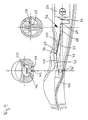
- Fig. 1 shows the ready-sprayed hard component 16, in which already a handle portion 10, a neck portion 12 and a head portion 14 are formed.
- the neck region 12 which holds the head region 14 and the grip region 10 at a distance preferably has a length in the range of 30 mm to 70 mm and in particular of approximately 50 mm.
- the neck region 12 connecting the grip region 10 and the head region 14 is tapered relative to the grip region 10 and the head region 14, as can be seen from the upper illustration of FIG Fig. 1 can be seen.
- the hard component 16 further comprises a neck 50 in cross-section U-shaped recess 50 for a vibration device.
- recesses 34 are formed, which are part of a vibration damping region 32.
- an electrical connection passage 52 extending from the front cavity 50 to the rear end region, a rear cavity 28 for an energy storage device in the form of a battery or a rechargeable accumulator of the AAA type, and a cavity 29 for actuating one are not illustrated switching element available.
- the latter cavity 29 communicates via an opening 56 with the channel 52 which has been widened in this area.
- the channel 52 extends at the bottom of the toothbrush.
- the hard component 16 further includes in the region of rear end a recess 58 for a U-shaped contact bracket.
- a functional assembly 82 is fixed to the hard component 16.
- This assembly 82 comprises a vibration device 22, an electric motor 20 and an eccentric 21 drivable by this with a length of 1.5-5 mm and a maximum diameter of 4-10 mm, which are arranged in a protective element, here a protective sleeve 23 ,
- a protective sleeve 23 With this vibration device 22, the head region 14 of the toothbrush can be excited to oscillations with a frequency of several 1000 Hz, preferably 10000-20000 Hz.
- the sleeve 23 serves on the one hand to protect the vibration device 22 against pressure and temperature effects of the subsequently to be sprayed plastic component and on the other hand to exempt the eccentric against the plastic material of this component.
- the injection-pressure-resistant sleeve 23 is made of plastic, ceramic or - preferably - metal, in particular of a nickel-plated brass alloy.
- the protective sleeve 23 may be formed by a plastic whose melting point is above the temperature of the subsequently to be sprayed plastic component. Reinforced plastics are preferably used, for example plastics reinforced with glass fibers.
- the outer length of the sleeve 23 is about 10 to 25 mm, preferably 21 mm, while the diameter of the sleeve 23 is about 2 to 10 mm, preferably 7 mm, and the wall thickness of the sleeve 23, up to 3 may be mm, preferably 0.5 mm.
- An optionally additionally attached cover lengthens the length of the protective element (sleeve and cover) by 1-4 mm, preferably 3.5 mm. If a lid is present, no pouring with resin is necessary.
- the sleeve 23 is closed after insertion of the eccentric 21 and the motor 20 either by means of a provided with passages for the power supply of the motor cover or with a liquid applied and then curing substance (eg a resin, paint or two-component glue).
- a stop is preferably provided on the sleeve 23, whereby too far advancement of the eccentric 21 is prevented during assembly. Free rotation of the eccentric is thus guaranteed.
- the assembly can be simplified with this embodiment.
- the vibration device is fixed by means of stiction or a slight interference fit in the recess of the hard component. This fixation is to be designed so that this functional element can not be washed away by the subsequently injected soft component from the intended place.
- Two electrical connection lines 42, 44 are connected to the vibration device 22. These are preferably provided in the form of a sheathed stranded or single wire made of copper, wherein the wire diameter, which may be up to 1 mm, is preferably 0.3 mm. The thickness of the sheath is in the range of 0.1 to 0.5 mm and is preferably 0.2 mm.
- the sheath is securely protected against the so-called flushing during the overmolding with the plastic, so that even if the electrical lines 42, 44 are moved due to the injection pressure, no short circuit can occur.
- An electrical lead 42 is made relatively short and extends to the aperture 56 between the widened portion of the channel 52 and the central cavity 29 (see FIG. Fig. 1 ).
- the short line 42 in this embodiment, with a designed as an axial extension of the line 42, pen ( Fig. 9 ) or platelike ( Fig. 2 ) Contact element 46 provided.
- the contact element 46 is made of metal, preferably made of a nickel-plated brass alloy. Via a switching element described in more detail elsewhere, the contact element 46 can be connected to the one pole of an energy store arranged in the rear cavity 28.
- the contact element 46 is preferably fixedly connected (eg soldered) to the short cable 42 and thus a part of the motor assembly.
- the electrical lines 42, 44 are already prefabricated as components of the prefabricated module 82 already to the required length.
- the free ends of the lines 42, 44 may also be already stripped and tinned, which is particularly advantageous if for contacting with other electrical functional components no solder joints, but non-positive connections are provided. This will be discussed in more detail below.
- the functional unit is already mounted prior to insertion into the toothbrush body and before encapsulation with the soft component.
- the contact element 46 and the U-shaped contact clip 48 are already firmly connected to the cable ends, in particular soldered. As a result, manufacturing uncertainties are excluded.
- the channel 52 is formed between the vibration damping area 34 and the extended channel area with fixing elements for the electrical connections.
- fixing elements for the electrical connections.
- the lines 42, 44 are secured against falling out and secured against train.
- channel constrictions, undercuts or separate elements made of metal or plastic can be used for fixing.
- the electrical components may be thermally and / or mechanically fused to the hard component.
- the contact pin 46 and the opening 56 are matched to one another such that the cavity 29 situated in the middle region is sealed from below by the penetration of plastic of the component subsequently to be sprayed.
- the contact clip is made of metal, preferably of a nickel-plated. Brass alloy, made. On the contact bracket is in conjunction with elsewhere Fig. 10 discussed in more detail.
- Fig. 3 shows the toothbrush according to the invention after spraying the soft component 18.
- the spraying of the soft component 18 takes place in a second cavity (mold cavity) of the injection mold into which the hard component 16 after loading with the above-described functional components (vibration device 22 from sleeve 23, eccentric 21, optionally sleeve cover and motor 20, electrical lines 42, 44, contact pin 46 and contact bracket 48) is inserted.
- the soft component 18 covers the functional components disposed on the hard component 16, i. These functional components are molded directly with the plastic component 18 forming plastic.
- the cavity 29 provided in the middle region is closed upwards.
- the soft elastic plastic of the soft component 18 here forms a pressing-in from the outside in the cavity 29 pushable switching portion 30 which is provided on its inside with two in the cavity 29 in the above switching projections 31.
- the formation of this switching region 30, which is also referred to as a switching membrane, does not take place with the aid of a illustrated mold core of the injection mold, which is introduced during the injection of the soft component 18 into the cavity 29.
- the soft elastic properties of the switching region 30 allow easy forced removal by pulling the mandrel backwards, whereby the resilient switching portion 30 is pressed over the switching projections 31 to the outside and then due to its elasticity again in Fig. 3 shown normal position occupies.
- the Shore hardness A of the switching region 30 is preferably less than 70, preferably less than 40, and is in particular about 35. In this range, the soft component has the optimum properties for the function of the damping elements, soft elastic cleaning elements and sealing elements and for the switching area for actuating the switch ,
- the vibration damping portion 32 is completed by forming the respective recesses 34 (see FIG. Fig. 1 ) of the hard component 16 are filled with the plastic of the soft component 18.
- Toothbrush body formed a circumferential sealing lip 64, which allows a waterproof attachment of a cover plate, which will be discussed in more detail elsewhere.
- the functions of the soft-elastic material are preferably realized with exactly one material from at least one injection point.
- various functions may be performed by means of various materials, e.g. with different Shore A hardnesses or colors, realized via different injection points.
- Fig. 4 from behind the switching element 36 (frog) introduced into the cavity 29.
- the frog 36 is fixed to a support portion 69 of the hard component 16 simply by plugging. This will be described below in connection with Fig. 9 discussed in more detail.
- a battery 24 in particular a battery of the AAA type (1.5 V), introduced from behind into the cavity 28 provided for this purpose.
- At the height of the spring portion are at the inside of the hard component at least one, preferably three to four elements 130 (see FIG. Fig. 19 ), which constitute a stop for the battery 24.
- the spring travel of the battery 24 can be accurately adjusted. In a fall of the brush from a greater height prevent the elements 130, the overbending of the spring element 66 by the battery.
- a lid 70 is placed on the rear end of the toothbrush body.
- the cover 70 is a preassembled module which comprises an electrically conductive contact section 72, via which, in the mounted state, an electrical connection between the other pole of the battery 24 on the one hand and the recess 58 in the hard component 16 (see FIG. Fig. 1 ) and then overmolded with the soft component 18 (cf. Fig. 3 ) Contact clip 48 is produced, whereby the electrical connection of all participating functional components is completed.
- connection between the cover 70 and the rear end of the toothbrush body with the interposition of the formed by spraying the soft component 18 sealing lip 64 takes place preferably in the manner of a bayonet closure, whereupon in conjunction with Fig. 10 and particularly Fig. 13 will be discussed in more detail.
- the connection can be made, for example, by other suitable means, such as by latching.
- the attachment of the head 76 on the head portion 14 of the hard component 16 can basically by any suitable means such as locking, gluing or welding, in particular ultrasonic welding done.
- the bristles directly to the hard component of the brush by means of a suitable bristling process.
- the brush is bristled before being filled with the electrical functional components and overmolding the soft component.
- additional soft-elastic cleaning and / or massage elements can then be attached directly to the brush head by means of the soft component.
- the bristles i.
- the placement of the head with cleaning and / or massage elements can basically be done by any process of bristling (e.g., IMT or AFT).
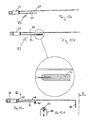
- Fig. 8 shows a previously mentioned Variant for producing an electrically conductive connection between the short electrical line 42 and the switching element (frog) 36.
- contact element 46 instead of the already in the prefabricated state fixed to the free end of the short electrical line 42 connected contact element 46 (see. Fig. 2 ) is provided according to this variant, a separate contact pin 46 ', which is introduced after attaching the prefabricated assembly 82 to the hard component 16 and before spraying the soft component 18 in a formed in this variant when spraying the hard component 16 recess, whereby an electrically conductive Connection between the contact pin 46 'and the free end of the short electrical line 42 is made. Via the contact pin 46 ', the switching element 36 can then be electrically connected to the short electrical line 42.
- This holding device may be a controlled slide which is brought into a working position during the injection process and presses the contact pin 46 'sealingly against the force of the incoming plastic mass against the boundary of the opening 56 to the upper cavity 29 or against a wall, the upper cavity 29 of the underneath lying receiving portion of the hard component 16 separates and has an opening for the contact pin 46 '.
- the fixation of the contact pin 46 ' is not effected by a slide, but simply by force-fitting pressing.
- the contact pin 46 'with holding means e.g. be provided in the form of Randrier Institute, surface roughening or Schufangept, whereby the production of an effective frictional connection is simplified. Accordingly, preferably, the insertion and fixing of the contact clip 48 in the recess 58 by non-positive pressing.
- Fig. 9 shows enlarged in the lower figure the area of the toothbrush body in which the switching element (frog) 36 is arranged.
- the frog is made of metal, preferably spring steel.
- the frog 36 has two legs 40 which are hinged together at a hinge portion 38.
- the in Fig. 9 left leg 40 serves for contacting the above-described separate contact pin 46 '(see. Fig. 8 ) or the integrated contact element 46 (cf. Fig. 2 and Fig. 4 ), for which purpose the respective leg 40 of the frog 36 can be modified, as it is, for example Fig. 4 evident.
- the contact pin is preferably an integral part of the motor assembly.
- the other leg 40 of the frog 36 is provided at its end with a plug portion 68, with which the frog 36 is slid over a dovetail-shaped in cross-section support portion 69 of the hard component 16 (see, the right enlarged detail in Fig. 9 ), whereby the frog 36 is fixed to the toothbrush body. Tooth-like projections on the insertion portion of the frog become wedged with the support portion formed from the hard component.
- the already mentioned spring portion 66 connects for contacting the one pole of the battery 24 at.
- the frog 36 can be reversed between two dimensionally stable states in order to switch the toothbrush on and off in this way.
- the in Fig. 9 shown on-state is by applying the in Fig. 9 the right leg 40 of the joint portion 38 moves downward, causing the frog 36 snaps from a certain depth of indentation and the in Fig. 9 left leg 40 jumps up and thus out of contact with the contact pin 46 'and 46 passes.
- the snapping of frog 36 is supported by parallel to in Fig. 9 right leg 40 extending arms 67, with the other, in Fig. 9 left leg 40 are connected.
- a ramp is additionally formed in the extension of the support section under the frog from the hard component (in Fig. 9 Not shown).
- FIG. 9 On the left shown enlarged detail shows in particular the means of the contact pin 46 'produced electrical connection between the free end of the short electrical line 42 and the leg 40 of the frog 36.
- the guided past the head of the contact pin 46' long electrical line 44 can be seen ,
- Fig. 10 shows a side view and a plan view of the rear end of the toothbrush body.
- the position of the recess 58 provided for the U-shaped contact clip 48 can be seen, while the left-hand side view shows how, by means of the contact clip 48 inserted into the recess 58, an electrical connection between the free end of the long electrical section Line 44 and the contact portion 72 of the lid 70, not otherwise shown here (see. Fig. 6 ) will be produced.
- the contact portion 72 of the lid 70 comprises a relative to the lid preferably resilient contact head 73 for contacting the battery 24 and a contact tongue 74, which radially via a cylindrical support portion 71 (see. Fig. 13 ), of which the contact portion 72 is held, protrudes.
- the contact tongue 74 serves on the one hand for contacting the contact clip 48 and on the other for locking the lid on the toothbrush body in the manner of a bayonet closure by the contact tongue 74, the legs of the U-shaped bracket 48 engages behind.
- the contact portion consisting of contact head and contact tongue is preferably formed in one piece and consists of metal, preferably spring steel. Of the Contact section is sunk in the lid so that the contact head can only perform a limited spring travel. After a certain, approved travel, the battery is on the cover. Thus, there is also here, as in the frog, a suspension travel limit, which prevents a fall of the brush from a greater height that the spring head can be deformed too much.
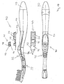
- Fig. 11 shows a preferred design of a toothbrush according to the invention produced by the method of the invention in various views.
- functional regions 60 produced in particular by spraying the soft component 18 are provided, which serve as a design feature for vibration damping and / or for a particularly good grip of the toothbrush according to the invention.
- the functional areas 60 serving as hand or finger rest are in the illustrated example on the rear side (i) in the area of the transition between the head area 14 and the neck area 12, (ii) in the grip area 12 at the level of an intermediate area between the vibration damping area 32 and the switching portion 30 and (iii) located in the region of the rear end of the handle portion 10.
- Another functional area 60 surrounds the two switching points 86 on the front side.
- Fig. 11 is the one of the Hard component and the soft component together formed vibration damping region 32 in the region of the transition between the handle portion 10 and neck portion 12, which has a reticulated geometry in this preferred design example.
- the lower plan view shows in particular the switching region 30 formed by the injected soft component with the two switching points 86, 88 for switching on (switching point 86) and switching off (switching point 88) of the toothbrush.
- the toothbrush according to the invention although it is an electrically operated toothbrush - an appealing elegant design without disturbing thickening or bulky areas on.
- the toothbrush according to the invention is provided with a neck section 12, which is particularly appealing from an aesthetic point of view and tapered with respect to the grip area.
- a slim design is made possible by the manufacturing method according to the invention, without this leading to concessions in terms of effort and time required in the manufacture of the toothbrush.
- Fig. 12a and 12b each show the prefabricated assembly 82, which is arranged in the embodiment described above prior to spraying the soft component 18 on the previously molded hard component 16 (see. Fig. 2 ). It shows Fig. 12a the variant without at the free end of the short electrical line 42 attached contact pin, ie this variant is used in conjunction with the above-described separate contact pin 46 '(see, in particular Fig. 8 ), while Fig. 12b in the Fig. 2-7 shown variant with soldered to the electrical line 42 contact pin 46 shows.
- Fig. 12c is shown another example of a motor assembly 82 which is already fully assembled prior to overmolding. Eccentric and motor are arranged in a protective sleeve 23 which is closed by a lid 23 '. Lines 42, 44 are guided by recesses in the lid 23 'to the outside. With the short line 42 of the contact pin 46 'is firmly connected, in particular soldered. The long line 44 is fixedly connected to the contact clip 48, in particular soldered.
- Fig. 12d shows a side view of the engine assembly in direction A.
- the vibration device 22 comprises in both cases the protective sleeve 23, in which the eccentric 21 and the motor 20 are arranged and which is filled after the introduction of these functional components with a resin or alternatively closed with a lid.
- Fig. 13 shows in the upper view of the toothbrush according to the invention in a closed state by means of the lid 7, while the lower view shows the toothbrush according to the invention before closing by means of the lid 70.
- the locking of the lid 70 on the toothbrush body by a bayonet closure takes place in the illustrated embodiment, the locking of the lid 70 on the toothbrush body by a bayonet closure.
- the Cover 70 is placed in an angular position with respect to the toothbrush body, in which with respect to a cylindrical support portion 71 of the lid 70 at opposite locations radially projecting contact tongue 74 of the contact portion 72 of the lid 70 is oriented so inclined to the legs of the U-shaped contact clip 48 that the contact tongue 74 inserted past the legs in the toothbrush body and the contact head 73 can come into contact with the rear pole of the battery 24.
- the contact tongue 74 engages with its two radially projecting end portions of the legs of the U-shaped contact clip 48.
- the lid 70 is securely locked and on the other hand, the electrical contact between the contact blade 74 and the contact clip 48 and thus between the long electrical line 44, the contact head 73 and the battery 24 made.
- the spring elements on the frog and contact section as well as those on the sealing lip provide an adjustable closing force for closing or opening the lid.
- a circular ring 100 made of the hard component can be formed, which engages in a corresponding groove 102 of the lid 70.
- this groove 102 may include an O-ring 104.
- the cover 70 may on its outer side for simplified opening and closing projections, ribs or recesses (not shown). These are to prevent slipping when turning.
- Fig. 14 shows a further embodiment of a toothbrush according to the invention, in which a control unit 90 is provided for the vibration device 22, which is arranged after spraying the hard component in a receiving portion 97 of the hard component and then over-molded as a whole with the soft component.
- the control unit 90 comprises a carrier 93, designed in particular as a circuit board, on which two batteries 24, for example commercially available button batteries (1.5 V), an integrated circuit 92 and a switch 91 are arranged Fig. 14 also shown separately enlarged.
- the switch 91 is in the illustrated preferred embodiment, a pulse switch, by means of which a switching operation is always triggered when the free tip end of an electrically conductive, spike-shaped switching element 95 contacts an electrically conductive mating contact 94 on the carrier or the board 93.
- the switching operations are triggered in each case by depressing an electrically conductive, deformable holder 98, to which the switching element 95 is attached and which is attached to the carrier 93.
- the switch 91 is designed such that when spraying the soft component and the space surrounding the switching element 95 is filled within the holder 98 with the plastic material of the soft component. As a result, the distance corresponding to the switching path of the switch 91 between the free contact end of the switching element 95 and the mating contact 94 is filled with plastic. At the first operation of the Switch 91, this material is pierced by the contact pin 95 and triggered a first switching operation. An automatic reset of the switching element 95 is due to the elasticity of the soft component, ie the depression of the switching element 95 via the holder 98 for triggering a switching operation takes place against the restoring force of the soft component.
- the vibration device 22 is connected to the control unit 90 via supply lines 96.
- the integrated circuit 92 may be designed to implement a wide variety of control functions. For example, it may be provided that the triggering of successive switching operations by means of the switch 91, the vibrator 22 alternately on and off. Alternatively, it can be provided, for example, that the vibration device 22 is switched on by a single actuation of the switch 91 and the circuit 92 ensures that the vibration device 22 is automatically switched off after a predetermined period of time without the switch 91 having to be actuated again for this purpose.
- the batteries 24 can be arranged offset from the control unit 90 and positioned, for example, in the rear region of the grip region and connected to the control unit 90 via additional supply lines.
- Toothbrushes described are preferably designed as disposable brushes, which are disposed of after the consumption of the batteries 24.
- the toothbrush can be designed in this way be that a removable cover portion is provided, through which the batteries 24 are accessible and can be replaced in order to use the toothbrush more frequently in this way.
- the switching area 30 is provided for actuating the switch 91 in the area of the thumb rest of the toothbrush.
- the switching region can also be arranged in the region of the rear end of the toothbrush and, for example, integrated in the rear end section of the toothbrush body or in the cover 70.
- the lid 70 is designed as a rotary switch and must be rotated relative to the toothbrush body by a predetermined angular range in order to trigger a switching operation.
- the vibration device 22 may be mounted directly on the carrier 93 of the control unit 90. This embodiment would on the one hand vibrations in the grip area result, but on the other hand could be dispensed with advantageously on supply lines between vibration device 22 and control unit 90.
- the positioning of the vibration device 22 in the vicinity of the toothbrush head according to Fig. 14 wherein the vibration damping portion 32 prevents vibrations in the grip portion of the toothbrush is preferably, the positioning of the vibration device 22 in the vicinity of the toothbrush head according to Fig. 14 wherein the vibration damping portion 32 prevents vibrations in the grip portion of the toothbrush.
- Fig. 15 shown further alternative embodiment of a toothbrush according to the invention substantially corresponds to the embodiment of Fig. 14 with the one difference that instead of a vibration device 22 another functional unit is connected to the control unit 90, namely a lighting device 22 'in the form of an LED or a light bulb.
- a lighting device 22 'in the form of an LED or a light bulb is connected to the control unit 90, namely a lighting device 22 'in the form of an LED or a light bulb.
- the illumination device 22 'in accordance with Fig. 15 merely represents a preferred example of a further functional unit and the functional unit may alternatively be provided in the form of a sensor designed for the particular desired application purpose.
- the soft-component-encased light source 22 ' can be a source of light that can be switched on and off as needed, permanently activated in the switched-on state, for illuminating the oral cavity.
- the light source 22 ' may be used as a timer which, after being turned on, flashes for a period of, for example, two minutes and then automatically turns off.
- An alternative or additional function may be to use the light source 22 'as a display means by which the user is informed of the end of the life of the toothbrush, for example by following a predetermined number of e.g. 200 turn-ons the light source 22 'e.g. no longer lit, operated with a changed flashing frequency or permanently lit, i. the end of the life is indicated by an operating mode of the light source 22 'changed from the normal state.
- Fig. 14 are all electrical components connected to the carrier 93, which is fixed by spraying the base body forming the hard component of the toothbrush by means of anchors on the body.
- the light source 22 ' may be mounted directly on the carrier 93.
- the switching path for the switching element 95 performing gap between the free end of the switching element 95 and the mating contact 94 is preferably less than 5 mm.
- the material thickness of the holder 95 carrying the switching element 98 which is preferably made of metal, for example spring steel, brass or copper, preferably has a material thickness of at least 0.5 mm in order to prevent deformation due to the injection pressure.
- the batteries 24 are preferably anchored to the support plate 93 by spot welding, so that upon injection of the soft component, the electrical contact between the batteries 24 and the support plate 93 remains secure.
- one or more batteries 24 may be mounted in parallel or in series.
- the integrated circuit 92 is preferably covered by a resinous layer to provide protection against the heat and pressure of spraying the soft component formed by a rubber-like soft elastic material.
- control unit 90 applies correspondingly to the control unit 90 of FIG Fig. 14 illustrated, a vibration device 22 instead of a light source 22 'comprehensive embodiment.
- a transparent or translucent rubber or soft elastic material is used as the soft component, which is the one of the Radiation source 22 'allows radiation to pass as freely as possible.
- Fig. 16 shows an example of a loading pallet 84, which is used in the largely automated production of the toothbrush according to the invention.
- the prefabricated assemblies 82 (cf. Fig. 12b ) are delivered in such a way that the assemblies 82 can be easily removed from the wells provided in the pallet 84 by means of a machine.
- Fig. 17 shows only schematically a plan view of an inventive for the production of trained according to the invention toothbrush assembly system, with a largely automatic handling and assembly of the individual components and components can be done.
- both a rotary table and a transfer system arrangement can be provided.
- Two or more injection molding machines are used, which are preferably provided with vertical aggregates for spraying the hard component and / or the soft component of the toothbrush body.
- the rotary table or transfer system arrangement is provided once or twice, while the injection molding machines are provided 4, 6 or 8 times, since the cycle time required for spraying is higher than the cycle time of the rotary table or transfer system arrangement.
- Deviating from the basis of Fig. 17 described procedure may, in particular depending on the specific embodiment of the toothbrush and another Order of the manufacturing steps can be provided. Furthermore, individual of these production steps can be omitted, which in particular in the case of Fig. 14 and 15 the disposable variant described is the case in which, for example, the above-mentioned step 5 of inserting the battery is omitted.
- Fig. 18a-d show further variants of a toothbrush according to the invention or its head part with a lighting device 22 '.
- Structure and function of the toothbrush correspond to the example Fig. 15 with the difference that the light source 118 (eg LED or light bulb) is placed in the head region 14.
- the arrangement of the luminous means 118 and the optical properties of the soft and hard components and optionally the bristles can be varied in order to realize different light distributions.
- the optical functional element is preferably placed so that its direction of illumination radiates between 45 ° and 90 ° from the brush head 14 and lies approximately at the center of gravity of the bristled surface. If a plurality of optical elements 118 are used, they are preferably also distributed so that the brush head surface is illuminated uniformly.
- the hard component 16 and the soft component 18 are substantially opaque, but the bristle carrier 120 and the bristles 80 are at least partially transparent.
- the light-emitting means 118 is located at a distance of preferably less than 2 mm below the bristle carrier 120 in a cavity 126. As a result, a uniform light distribution is realized.
- a brush head which is produced by the AFT method (Anchor Free Tufting).
- AFT method Anchor Free Tufting
- individual bristles or bristle bundles are passed through holes in the bristle carrier and melted on the back.
- the bristle melt 122 distributes the light evenly into the bristle tips 124, so that the bristles assume the function of light guides.
- Optional soft-elastic cleaning elements 132 may also serve for light transmission.
- Fig. 18c shows a toothbrush, in which the light emitting means 118 additionally radiates on the back 15 of the head part 14.
- the luminous means 118 is only partially encapsulated by the soft-elastic component 18.
- a translucent opening 128 on the brush head back can be used for treatment with gum and oral cavity light. With this option, the light source can be placed directly on the site to be treated. The light can thus unfold its full visual effect in the oral cavity.
- the elastic soft component seals the cavity 126 and the opening 128 below the bristle carrier 120.
- the light source 118 on the back of the brush head 15 is coated only with a thin layer of soft elastic material 18.
- the light emitted in this direction therefore assumes the color of the preferably at least partially transparent soft component 18.
- toothbrushes according to Figs. 18c and 18d they are brushes with a replaceable head (not hatched part).
- toothbrushes with optical Functional units are for example an antibacterial effect, light therapy, or the control of Aften etc.
- optical functional elements can be used, which can change their color.
- toothbrushes can be produced, which convey a special fun on brushing teeth, especially with colored lights or flashing. In the latter aspect, a combination with the sensor described below is also conceivable, eg flashing only when performing a cleaning movement.
- a separately prepared bristle carrier 120 If a separately prepared bristle carrier 120 is used, its hard component should be at least partially translucent. By a corresponding color tone different brush heads can produce different colors with the same particular white light source.
- Transparent or translucent rubber-elastic structures 132 or cleaning elements on the brush head can preferably be used to direct the light from the optical element to the intended location.
- Fig. 19 shows an example of a toothbrush, which instead of or in addition to a manually operated switch (not shown here) is equipped with a movement or pressure sensor 106, which can be used in particular as a pressure sensor.
- the sensor 106 is located between the neck region 12 and the grip region 10, is capable of interrupting or producing the power supply of the luminous means or of an acoustic element 114, and thus replaces the switching element 36 described above.
- the sensor 106 comprises a Contact plate 108 and a contact tip 110, which are each connected to a supply line 42, 44. Both contact elements 108, 110 are movable relative to one another and separated from each other by an elastic material region 116 which projects into the hard material 16 at a point into which the contact tip 110 is embedded.
- the neck portion 12 bends opposite the handle portion 10, and the contact tip 110 pierces the resilient material portion 116 to form an electrically conductive connection and close the circuit.
- the acoustic element 114 thus emits a sound when the neck area undergoes a certain critical bend.
- the line 44 is here directly connected to the carrier 93.
- the switch acts in this embodiment variant as a pressure sensor with respect to the contact pressure of the toothbrush head against the toothbrush.
- the acoustic element 114 is not overmoulded here, but is mounted like the frog and the battery after spraying the soft component.
- Fig. 19 are also the elements 130 described above, which form a stop for the battery 24 to prevent overstretching of the spring 66.
Abstract
Description
Die Erfindung betrifft ein Verfahren zur Herstellung einer Zahnbürste mit einem einen Griffbereich, einen Kopfbereich und einen zwischen dem Griffbereich und dem Kopfbereich gelegenen Halsbereich umfassenden Körper und mit zumindest teilweise innerhalb des Körpers angeordneten Funktionsbauteilen, die eine elektrisch betriebene Funktionseinheit und eine einen Energiespeicher aufweisende elektrische Versorgungseinrichtung für die Funktionseinheit umfassen.The invention relates to a method for producing a toothbrush having a body comprising a grip region, a head region and a neck region located between the grip region and the head region and functional components arranged at least partially within the body, comprising an electrically operated functional unit and an electrical supply device having an energy store for the functional unit.
Derartige Zahnbürsten sind grundsätzlich bekannt.Such toothbrushes are known in principle.
Die
In der
Die
In der
Bei der Herstellung derartiger Zahnbürsten kommt es insbesondere darauf an, dass die innerhalb des Körpers angeordneten Funktionsbauteile korrekt positioniert sind und eine sichere sowie zuverlässige Funktionsweise gewährleistet ist. Da derartige Zahnbürsten meist in großen Stückzahlen hergestellt werden, soll ferner die Herstellung im Rahmen einer kostengünstigen und effizienten Massenproduktion möglich sein. Nachdem des Weiteren das äußere Erscheinungsbild der Zahnbürste für die Kaufentscheidung zunehmend eine nicht unwesentliche Rolle spielt, soll die Konstruktion der Zahnbürste eine möglichst große Designfreiheit erlauben, welcher bei der Herstellung der Zahnbürste Rechnung getragen werden muss. Dabei kommt es nicht nur darauf an, eine ergonomisch vorteilhafte Zahnbürste zu schaffen, die "gut in der Hand liegt", sondern die Zahnbürste muss außerdem einfach bedienbar sein, während der Benutzung sicher festgehalten werden können und eine einwandfreie, sich angenehm anfühlende Oberfläche aufweisen, d.h. der Benutzer soll die Zahnbürste einfach "gerne in die Hand nehmen" wollen.In the production of such toothbrushes, it is particularly important that the arranged within the body functional components are positioned correctly and a safe and reliable operation is guaranteed. Since such toothbrushes are usually produced in large quantities, should also be possible in the context of a cost-effective and efficient mass production. Furthermore, since the external appearance of the toothbrush plays an increasingly important role in the purchase decision, the construction of the toothbrush should allow as much design freedom as possible, which must be borne in mind when manufacturing the toothbrush. It is not only important to create an ergonomically advantageous toothbrush, which "fits well in the hand", but the toothbrush must also be easy to use, can be securely held during use and have a flawless, pleasant-feeling surface, ie The user should simply like to "take the toothbrush" in his hand.
Die in
Bei dem in
Die
Der Erfindung liegt die Aufgabe zugrunde, eine Möglichkeit zur Herstellung von Zahnbürsten zu schaffen, die den eingangs erwähnten Anforderungen gerecht wird und bei der insbesondere mit einer minimalen Anzahl von erforderlichen Spritzgiesswerkzeugen und Montageschritten gleichzeitig eine maximale Designfreiheit gegeben ist, wobei insbesondere die Herstellung eines gebogenen Halsbereichs möglich sein soll.The invention has for its object to provide a way to produce toothbrushes, which meets the above-mentioned requirements and in which a maximum design freedom is given at the same time with a minimum number of required injection molds and assembly steps, in particular the production of a curved neck should be possible.
Die Lösung dieser Aufgabe erfolgt durch die Merkmale des unabhängigen Verfahrensanspruchs 1 und insbesondere dadurch, dass der Körper aus zumindest einer als Festigkeitsträger dienenden Hartkomponente sowie wenigstens einer Weichkomponente im Spritzgiessverfahren hergestellt wird, und dass wenigstens einige der Funktionsbauteile während der Herstellung des Körpers zumindest teilweise direkt mit dem die Weichkomponente bildenden Kunststoff umspritzt werden.The solution of this object is achieved by the features of the
Die Erfindung betrifft außerdem eine Zahnbürste nach Anspruch 16, bei der wenigstens einige Funktionsbauteile zumindest teilweise direkt mit dem die Weichkomponente des Zahnbürstenkörpers bildenden Kunststoff umspritzt sind.The invention also relates to a toothbrush according to
Bevorzugte Ausführungsformen der Erfindung sind in den abhängigen Ansprüchen, der Beschreibung sowie der Zeichnung angegeben.Preferred embodiments of the invention are indicated in the dependent claims, the description and the drawings.
Die Herstellung des Zahnbürstenkörpers aus wenigstens einer Hartkomponente und zumindest einer Weichkomponente ermöglicht eine hohe Designfreiheit bei gleichzeitiger Erfüllung der Stabilitäts- und Festigkeitsanforderungen an die Zahnbürste.The production of the toothbrush body from at least one hard component and at least one soft component allows a high design freedom while fulfilling the stability and strength requirements of the toothbrush.
Durch das erfindungsgemäß vorgesehene direkte Umspritzen der Funktionsbauteile mit dem Kunststoff erfolgt eine optimale Integration der Funktionsbauteile in den Zahnbürstenkörper. Somit können bereits bei der Herstellung des Körpers die Funktionsbauteile an den dem jeweiligen Design entsprechenden Stellen im Körper positioniert werden, wodurch dem Designer ein maximaler Spielraum für die Formgestaltung der Zahnbürste verliehen wird. Ferner wird durch die erfindungsgemäße Vorgehensweise die Zahnbürstenherstellung erheblich verkürzt und vereinfacht, da Spritz- und Montageschritte gleichzeitig oder unmittelbar nacheinander erfolgen können. Des Weiteren ist von Vorteil, dass die Funktionsteile durch das direkte Umspritzen mit dem Kunststoff automatisch am Zahnbürstenkörper fixiert werden, was die Durchführung ggf. erforderlicher weiterer Herstellungsschritte vereinfacht.The inventively provided direct encapsulation of the functional components with the plastic is an optimal integration of the functional components in the toothbrush body. Thus, already in the manufacture of the body, the functional components can be positioned at the positions corresponding to the respective design in the body, whereby the designer is given maximum flexibility for shaping the toothbrush. Furthermore, the toothbrush production is considerably shortened and simplified by the procedure according to the invention, since injection and assembly steps can take place simultaneously or immediately one after the other. Furthermore, it is advantageous that the functional parts are automatically fixed to the toothbrush body by the direct encapsulation with the plastic, which simplifies the carrying out of possibly required further production steps.
Von besonderem Vorteil ist außerdem, dass die Funktionsbauteile durch das Umspritzen optimal vor äußeren Einflüssen geschützt und insbesondere wasserdicht eingekapselt werden können.Of particular advantage is also that the functional components can be optimally protected by encapsulation against external influences and in particular encapsulated waterproof.
Die Erfindung bedeutet eine Abkehr von der bekannten Vorgehensweise bei der Zahnbürstenherstellung, bei der eine strenge Trennung zwischen Spritzgiessschritten einerseits und Montageschritten andererseits eingehalten wird. Erfindungsgemäß wurde festgestellt, dass grundsätzlich die Funktionsbauteile den beim Kunststoffspritzen auftretenden Druck- und Temperaturbelastungen ausgesetzt werden können, ohne dass die Funktionsfähigkeit der Bauteile beeinträchtigt wird. Das Einbetten wenigstens einiger der Funktionsbauteile in die Weichkomponente hat des weiteren den Vorteil, dass der Spritzvorgang schonender für die Funktionsbauteile ist, da der Spritzdruck der Weichkomponente geringer als der der Hartkomponente ist. Die Weichkomponente hat ausserdem eine hohe Fliessfähigkeit, so dass die Funktionsbauteile zuverlässig umschlossen werden, auch wenn sie kompliziert geformt sein sollten. Ein weiterer Vorteil ist, dass die Funktionsbauteile in einem Arbeitsgang mit weiteren, sowieso bei den meisten Zahnbürsten vorhandenen weichelastischen Elementen, z.B. weichelastische Reinigungselemente am Borstenfeld oder eine elastische Zone im Halsbereich, gespritzt werden können. Damit ist kein zusätzlicher Herstellungsschritt notwendig.The invention means a departure from the known procedure in the manufacture of toothbrushes, in which a strict separation between injection molding steps on the one hand and assembly steps on the other hand is adhered to. According to the invention, it has been found that, in principle, the functional components can be exposed to the pressure and temperature stresses which occur during the injection molding of plastics without the functional capability of the components being impaired. The embedding of at least some of the functional components in the soft component has the further advantage that the Spraying is gentler for the functional components, since the injection pressure of the soft component is lower than that of the hard component. The soft component also has a high flowability, so that the functional components are reliably enclosed, even if they should be formed complicated. Another advantage is that the functional components can be sprayed in one operation with other soft-elastic elements that are present in most toothbrushes, for example soft-elastic cleaning elements on the bristle field or an elastic zone in the neck region. Thus, no additional manufacturing step is necessary.
Die erfindungsgemässe Zahnbürste hat den weiteren Vorteil, dass die Weichkomponente die Funktionsbauteile einbettet, schützt, gegebenenfalls abdichtet, jedoch aufgrund der elastischen Eigenschaften ihre Betätigung von Aussen und Kommunikation bzw. Interaktion (z.B. Betätigung, Informationsübertragung, Energieübertragung) mit der Aussenwelt ermöglicht. In einer vorteilhaften Weiterbildung der Erfindung, die weiter unten erläutert wird, fungieren die Funktionsbauteile in Verbindung mit der Weichkomponente auch als mechanischer Sensor, z.B. zur Überwachung des Putzdrucks.The toothbrush according to the invention has the further advantage that the soft component embeds, protects and possibly seals the functional components, but because of its elastic properties enables its external actuation and communication or interaction (for example actuation, information transmission, energy transmission) with the outside world. In an advantageous embodiment of the invention, which is explained below, the functional components in conjunction with the soft component also function as a mechanical sensor, e.g. for monitoring the plaster pressure.
In einer besonders bevorzugten Variante des erfindungsgemäßen Herstellungsverfahrens wird zunächst eine erste, bevorzugt harte, Komponente ohne Funktionsbauteile gespritzt. Diese hat vorzugsweise eine Aufnahme für die Funktionsbauteile, beispielsweise eine im Querschnitt U-förmige Ausnehmung an der Zahnbürstenrückseite, die vor dem Überspritzen auf einfache Weise befüllt werden kann.In a particularly preferred variant of the production method according to the invention, first a first, preferably hard, component is sprayed without functional components. This preferably has a receptacle for the functional components, for example, a cross-sectionally U-shaped recess on the toothbrush back, which can be filled before over-molding in a simple manner.
Nach dem Spritzen der ersten Komponente werden zumindest einige Funktionsbauteile an der ersten Komponente positioniert und fixiert, wobei anschließend die Einheit aus erster Komponente und Funktionsbauteilen mit zumindest einer weiteren, bevorzugt weichen Komponente zumindest teilweise umspritzt wird. Bei dieser Variante ist von Vorteil, dass für die zu umspritzenden Funktionsbauteile keine speziellen Maßnahmen zum Festhalten am Spritzwerkzeug getroffen werden müssen. Insbesondere dann, wenn die erste Spritzkomponente eine Hartkomponente und die weitere Spritzkomponente eine Weichkomponente ist, bietet diese Variante den weiteren Vorteil einer besonderen Schonung der mit der Weichkomponente zu umspritzenden Funktionsbauteile, da Weichkomponenten zumindest in den meisten Fällen mit im Vergleich zur Hartkomponente geringem Druck und niedriger Temperatur gespritzt werden können.After spraying the first component, at least some functional components are positioned and fixed to the first component, wherein subsequently the unit of the first component and functional components is at least partially encapsulated with at least one further, preferably soft component. In this variant, it is advantageous that no special measures for holding on the injection mold must be made for the functional components to be molded. In particular, when the first injection component is a hard component and the further injection component is a soft component, this variant offers the further advantage of special protection of the functional components to be overmoulded with the soft component, since soft components, at least in most cases, have low pressure and lower compared to the hard component Temperature can be sprayed.
Gemäß einer alternativen Variante werden vor dem Spritzen einer ersten Komponente zumindest einige Funktionsbauteile in einem Spritzgiesswerkzeug positioniert und daraufhin mit der ersten Komponente umspritzt, wobei anschließend die Einheit aus erster Komponente und umspritzten Funktionsbauteilen mit zumindest einer weiteren Komponente umspritzt werden. Da bei dieser Variante die Funktionsbauteile zunächst am Spritzgiesswerkzeug positioniert werden und daher das Formwerkzeug zum Halten der Funktionsbauteile an diesen angreifen muss, ist nach dem Spritzen der ersten Komponente diese mit Freistellungen für die Angriffspunkte an den vorpositionierten Funktionsbauteilen versehen. Beim Spritzen der weiteren Komponente werden diese Freistellungen geschlossen, so dass sie am fertigen Produkt nicht mehr zu erkennen sind.According to an alternative variant, at least some functional components are positioned in an injection mold and then encapsulated with the first component prior to spraying a first component, wherein subsequently the unit of the first component and overmolded functional components are encapsulated with at least one further component. Since in this variant, the functional components are first positioned on the injection mold and therefore the mold must hold to hold the functional components of these, after spraying the first component this is provided with exemptions for the points of attack on the prepositioned functional components. When injecting the other component, these exemptions are closed, so that they are no longer recognizable on the finished product.
Um die Belastungen der Funktionsbauteile durch das Spritzen weiter zu minimieren, kann gemäß einem weiteren Ausführungsbeispiel der Erfindung vorgesehen sein, dass zumindest bei einer Komponente zunächst in einem ersten Schritt bei niedrigem Spritzdruck eine Überdeckung der Funktionsbauteile gebildet und anschließend in wenigstens einem weiteren Schritt die Komponente bei hohem Spritzdruck vervollständigt wird.In order to further minimize the stresses on the functional components by spraying, according to a further exemplary embodiment of the invention, at least one component initially forms a covering of the functional components at low injection pressure in a first step, and then the component in at least one further step high injection pressure is completed.
Des Weiteren ist in einer Variante der Erfindung vorgesehen, dass vor dem Spritzen einer weiteren Komponente an der Einheit aus zumindest einer ersten Komponente und zu umspritzenden Funktionsbauteilen wenigstens ein weiteres zu umspritzendes Funktionsbauteil fixiert wird. Bei diesem weiteren Funktionsbauteil handelt es sich insbesondere um ein z.B. stift-, klammer- oder bügelförmiges Kontaktelement zur Herstellung einer elektrischen Verbindung zwischen zwei oder mehreren anderen Funktionsbauteilen.Furthermore, it is provided in a variant of the invention that at least one further functional component to be encapsulated is fixed prior to the injection of a further component on the unit of at least one first component and functional components to be encapsulated. This further functional component is in particular a e.g. pin, staple or bow-shaped contact element for producing an electrical connection between two or more other functional components.
Die Funktionsbauteile können in vorteilhafter Weise für einen Zusatzzweck genutzt werden, wenn gemäß einer weiteren bevorzugten Ausführungsform der Erfindung wenigstens ein für ein oder mehrere später einzusetzende Funktionsbauteile vorgesehener Hohlraum einer ersten Komponente durch wenigstens ein mit der ersten Komponente umspritztes und/oder mit wenigstens einer weiteren Komponente zu umspritzendes Funktionsbauteil gegenüber einer weiteren Komponente abgedichtet wird.The functional components can be advantageously used for an additional purpose if, according to a further preferred embodiment of the invention, at least one provided for one or more functional components later cavity of a first component by at least one overmolded with the first component and / or at least one further component is sealed to overmolding functional component against another component.
Gemäß einem weiteren bevorzugten Ausführungsbeispiel der Erfindung ist vorgesehen, dass durch Spritzen einer Weichkomponente ein zum Betätigen wenigstens eines elektrischen Funktionsbauteils in einen Hohlraum einer zuvor gespritzten Hartkomponente eindrückbarer Betätigungsbereich ausgebildet wird. Hierdurch werden in vorteilhafter Weise die elastischen Eigenschaften der Weichkomponente genutzt, um einen Betätigungsbereich z.B. zum Beaufschlagen eines im Zahnbürstenkörper angeordneten Schaltelementes zum Ein- und Ausschalten der Zahnbürste zu schaffen.According to a further preferred embodiment of the invention, it is provided that by spraying a soft component for actuating at least one electrical functional component in a cavity of a previously molded hard component depressible actuating portion is formed. As a result, the elastic properties of the soft component are used in an advantageous manner in order to create an actuating region, for example for applying a toothbrush body arranged in the switching element for switching on and off the toothbrush.
Des Weiteren wird erfindungsgemäß vorgeschlagen, einen insbesondere im Halsbereich oder im Bereich des Übergangs zwischen Halsbereich und Griffbereich gelegenen Vibrationsdämpfungsbereich des Körpers aus wenigstens zwei unterschiedlichen Spritzgiesskomponenten herzustellen. Hierdurch können die Dämpfungseigenschaften des Dämpfungsbereiches gezielt an die jeweiligen Erfordernisse angepasst werden. Besonders bevorzugt ist es, wenn der Vibrationsdämpfungsbereich durch eine gezielte Schwächung einer Hartkomponente mittels einer Weichkomponente gebildet wird.Furthermore, it is proposed according to the invention to produce a vibration damping region of the body, which is located in particular in the neck region or in the region of the transition between neck region and grip region, of at least two different injection molding components. As a result, the damping properties of the damping region can be specifically adapted to the respective requirements. It is particularly preferred if the vibration damping region is formed by a targeted weakening of a hard component by means of a soft component.
Zur Bildung des Vibrationsdämpfungsbereiches ist es bevorzugt, wenn zunächst beim Spritzen einer Hartkomponente diese mit einem Muster von Ausnehmungen hergestellt wird und anschließend beim Spritzen wenigstens einer weiteren Komponente, bei der es sich insbesondere um eine Weichkomponente handelt, mit dieser die Ausnehmungen gefüllt werden.In order to form the vibration damping region, it is preferred if, during the spraying of a hard component, it is first produced with a pattern of recesses and subsequently filled with the recesses during spraying of at least one further component, which is in particular a soft component.
Eine elektrische Verbindung zwischen einer im Kopfbereich oder im Halsbereich angeordneten Vibrationseinrichtung einerseits und einem im Griffbereich angeordneten Energiespeicher andererseits ist vorzugsweise über ein bistabiles Schaltelement herstellbar bzw. unterbrechbar, das durch Beaufschlagen an zwei auf gegenüberliegenden Seiten eines Gelenkbereiches gelegenen Schenkeln zwischen zwei zumindest im Wesentlichen formstabilen Zuständen umgesteuert werden kann.An electrical connection between a vibration device arranged in the head region or in the neck region, on the one hand, and an energy reservoir arranged in the grip region, on the other hand, can preferably be produced or interrupted via a bistable switching element, which can be interrupted by acting on two opposite ones Side of a joint region located legs between two at least substantially dimensionally stable states can be reversed.
Ein derartiges bistabiles Schaltelement, das auch als "Frosch" bezeichnet wird, kann insbesondere durch einen von einer gespritzten Weichkomponente gebildeten Schaltbereich, der vom Benutzer in einen Hohlraum, in welchem der Frosch angeordnet ist, hineingedrückt werden kann, betätigt werden.Such a bistable switching element, which is also referred to as "frog", can be actuated in particular by a switching region formed by a molded soft component, which can be pressed by the user into a cavity in which the frog is arranged.
Bei den Funktionsbauteilen, die direkt mit zumindest einer Kunststoffkomponente umspritzt werden, handelt es sich insbesondere um
- eine Vibrationseinrichtung, die bevorzugt eine Anordnung aus Elektromotor und Exzenter oder einen elektromagnetisch angetriebenen Schwinganker umfasst,
- mit der Vibrationseinrichtung verbundene elektrische Leitungen,
- separate Kontaktelemente, die dazu dienen, elektrische Verbindungen zwischen den anderen Funktionsbauteilen herzustellen.
- a vibration device, which preferably comprises an arrangement of electric motor and eccentric or an electromagnetically driven oscillating armature,
- electrical lines connected to the vibration device,
- separate contact elements that serve to make electrical connections between the other functional components.
Grundsätzlich können die zu umspritzenden Funktionsbauteile - in Abhängigkeit von der jeweiligen Konstruktion der Zahnbürste - außerdem Sensoren (z.B. Sensoren zur Druck- und Zeitmessung, zum Plaque-Nachweis, zur Positionsbestimmung, zur Bewegungsermittlung sowie zur Detektion von chemischen Substanzen oder Zusammensetzungen), Licht emittierende Bauteile, Widerstände, ICs, Schalteinrichtungen sowie akustische Bauelemente umfassen. Des weiteren können Steckkontakte (Buchse), z.B. zum Aufladen der Energiequelle oder zur Strom- oder Datenübertragung, Datenträger, z.B. Mikrochips, oder ein beispielsweise zum Diebstahlschutz einsetzbarer Passivsender (Radio Frequency Identification Chip) vorhanden sein. Bei gewissen Anwendungen, z.B. bei Verwendung eines Passivsenders, ist es entbehrlich, eine Energiequelle in die Zahnbürste zu integrieren.In principle, the functional components to be molded-depending on the particular construction of the toothbrush-can also be sensors (eg sensors for pressure and time measurement, plaque detection, position determination, movement detection and for the detection of chemical substances or compositions), light-emitting components , Resistors, ICs, switching devices as well as acoustic Components include. Furthermore, plug contacts (socket), eg for charging the energy source or for power or data transmission, data carriers, eg microchips, or a passable transmitter (Radio Frequency Identification Chip) which can be used, for example, for theft protection, may be present. In certain applications, such as when using a passive transmitter, it is unnecessary to integrate an energy source in the toothbrush.
Durch das Überspritzen mit der zweiten Komponente werden die Funktionsbauteile am vorgesehenen Standort fixiert, bei Einsatz der weichelastischen Komponente falls nötig flexibel gelagert und im überspritzten Bereich gegen das Eindringen von Wasser abgedichtet. Eine Möglichkeit, mit der Aussenwelt Kontakt herzustellen, ist das Überspritzen von Funktionsbauteilen mit einer dünnen Schicht der Weichkomponente, die zur Herstellung einer leitenden Verbindung durchstochen werden kann. Die gummielastische Weichkomponente hat die Eigenschaft, sich nach dem Entfernen des spitzen Kontaktgebers wieder wasserdicht zu verschliessen. Ein ähnliches Prinzip kann eingesetzt werden, um innerhalb der Zahnbürste eine leitfähige Verbindung zwischen Komponenten herzustellen, die relativ zueinander z.B. durch Biegen der Bürste beweglich sind.By overmolding with the second component, the functional components are fixed at the intended location, if necessary flexibly stored when using the soft elastic component and sealed in the overmolded area against the ingress of water. One way to make contact with the outside world is to over-spray functional components with a thin layer of the soft component that can be pierced to make a conductive connection. The rubber-elastic soft component has the property to seal again after removal of the pointed contactor waterproof. A similar principle may be employed to provide a conductive connection within the toothbrush between components which are relatively fixed relative to one another, e.g. are movable by bending the brush.
Es kann sich bei den Funktionsbauteilen also um elektronische Bauelemente handeln, die eine vergleichsweise große Empfindlichkeit gegenüber äußeren Einflüssen aufweisen können. Die Funktionsbauteile können mit einer Schutzummantelung beispielsweise aus Kunststoff, Keramik oder Metall versehen sein. Außerdem können die Funktionsbauteile mit einem Harz oder einem anderen Schutzmaterial umgossen sein.The functional components may therefore be electronic components which may have a comparatively high sensitivity to external influences. The functional components may be provided with a protective coating, for example made of plastic, ceramic or metal. In addition, the functional components may be encapsulated with a resin or other protective material.
Um die Belastungen der zu umspritzenden Funktionsbauteile auf ein Minimum zu reduzieren, ist es erfindungsgemäß bevorzugt, wenn mit einem relativ niedrigen Spritzdruck gearbeitet wird, wobei jedoch gleichzeitig eine homogene Materialverteilung im jeweiligen Spritzgiessteil sichergestellt wird. Bevorzugt werden besonders leicht fließende Kunststoffe verwendet. Das erfindungsgemäß bevorzugte Material ist Polypropylen (PP) mit einem Fliessindex von MVR 4 - 25, wobei insbesondere PP mit einem Fließindex von MVR 20 zum Einsatz kommt.In order to minimize the loads on the functional components to be overmolded, it is preferred according to the invention to operate with a relatively low injection pressure, but at the same time a homogeneous material distribution in the respective injection-molded part is ensured. Preference is given to using particularly easily flowing plastics. The inventively preferred material is polypropylene (PP) with a flow index of MVR 4-25, in particular PP with a flow index of
Ferner sind erfindungsgemäß vorzugsweise relativ niedrige Verarbeitungstemperaturen vorgesehen. Insbesondere dann, wenn gemäß der vorstehend erwähnten besonders bevorzugten Variante zunächst eine erste Komponente ohne Funktionsbauteile gespritzt wird, wird als bevorzugtes Material TPE verwendet, und zwar bei einer Temperatur im Bereich von 170°C bis 250°C, vorzugsweise von etwa 200°C.Furthermore, according to the invention preferably relatively low processing temperatures are provided. In particular, if, according to the above-mentioned particularly preferred variant, a first component is first sprayed without functional components, TPE is used as the preferred material, namely at a temperature in the range of 170 ° C to 250 ° C, preferably of about 200 ° C.
Erfindungsgemäß kann beim Spritzen der Komponenten jeweils sowohl entweder ein einziger Anspritzpunkt oder eine Mehrzahl von Anspritzpunkten verwendet werden. Im Fall eines einzigen Anspritzpunktes wird dessen Position vorzugsweise derart gewählt, dass das empfindlichste Funktionsbauteil in einer möglichst großen Entfernung vom Anspritzpunkt gelegen ist, so dass ein möglichst langer Kunststofffüllweg bis zu diesem Funktionsbauteil zurückgelegt werden muss. Bei Verwendung sowohl eines einzigen Anspritzpunktes als auch mehrerer Anspritzpunkte kann außerdem jeweils mit einem zeitlich variierenden Spritzdruck gearbeitet werden. Der Druckverlauf kann dabei gezielt an die jeweiligen Gegebenheiten angepasst werden. Insbesondere an dem dem empfindlichsten Funktionsbauteil nächstgelegenen Anspritzpunkt kann mit einem relativ geringen Nachdruck von weniger als 600 bar und vorzugsweise von weniger als 200 bar gearbeitet werden.According to the invention, either one single injection point or a plurality of injection points can be used in each case during spraying of the components. In the case of a single injection point, its position is preferably selected such that the most sensitive functional component is located at the greatest possible distance from the injection point, so that as long as possible a plastic filling path has to be covered up to this functional component. When using both a single injection point as well as multiple injection points can also be used in each case with a time varying injection pressure. The pressure curve can be adjusted specifically to the particular circumstances. In particular, at the most sensitive function component closest injection point can with a relative low holding pressure of less than 600 bar and preferably less than 200 bar.
Was die verwendeten Kunststoffmaterialien anbetrifft, so kann für eine Hartkomponente des Zahnbürstenkörpers z.B. Acrylbutadienstyrol (ABS), Polystyrol (PS), Polyethylenterephtalat (PET), Styrol-Acrylnitril (SAN), Polycarbonat (PC), Polyamid (PA) oder PolymethylMethacrylat (PMMA) verwendet werden, wobei das bevorzugte Material PP ist. Für die Weichkomponente wird vorzugsweise ein zur jeweiligen Hartkomponente affines, d.h. ein sich mit der Hartkomponente verbindendes, thermoplastisches Elastomer (TPE) verwendet, wodurch besonders geeignete weichelastische bzw. gummielastische Eigenschaften erzielt werden können.As for the plastic materials used, for a hard component of the toothbrush body, e.g. Acrylic butadiene styrene (ABS), polystyrene (PS), polyethylene terephthalate (PET), styrene-acrylonitrile (SAN), polycarbonate (PC), polyamide (PA) or polymethyl methacrylate (PMMA), the preferred material being PP. For the soft component, it is preferable to affine one affine to the respective hard component, i. a thermoplastic elastomer (TPE) which combines with the hard component, whereby particularly suitable soft-elastic or rubber-elastic properties can be achieved.
Für zumindest eine Komponente des Zahnbürstenkörpers kann ein lichtdurchlässiger bzw. transparenter oder zumindest transluzenter Kunststoff vorgesehen sein. Hierfür kommt insbesondere MABS, SAN, PA, PC, PMMA, PS oder PET in Frage. Bei der Verarbeitung von transparenten Kunststoffen wird bevorzugt mit einem vergleichsweise hohen Spritzdruck gearbeitet, wofür die vorstehend erwähnte Variante, bei der zunächst eine erste Komponente ohne Funktionsbauteile gespritzt wird, besonders geeignet ist.For at least one component of the toothbrush body, a translucent or at least translucent plastic may be provided. MABS, SAN, PA, PC, PMMA, PS or PET are particularly suitable for this purpose. In the processing of transparent plastics is preferably carried out with a relatively high injection pressure, for which the above-mentioned variant in which initially a first component is sprayed without functional components, is particularly suitable.
Des Weiteren ist erfindungsgemäß vorzugsweise vorgesehen, dass entweder an keiner Stelle oder zumindest in solchen Regionen des Zahnbürstenkörpers, die relativ großen Kräften wie insbesondere Biege- und Torsionskräften ausgesetzt sind, eine vorgegebene Mindestwandstärke des Kunststoffs nicht unterschritten wird. Bei der Hartkomponente wird bevorzugt ein Wert von etwa 0,5 mm für diese minimale Wandstärke nicht unterschritten, wobei vorzugsweise die Mindestwandstärke im Bereich von 1 bis 5 mm liegt. Eine Region, an welcher bis auf die Mindestwandstärke herunter gegangen wird, ist vorzugsweise der Bereich des Halses, an welchem die Vibrationseinrichtung angeordnet ist.Furthermore, according to the invention it is preferably provided that either at no point or at least in those regions of the toothbrush body which are exposed to relatively large forces, in particular bending and torsional forces, a predetermined minimum wall thickness of the plastic is not exceeded. The hard component preferably does not fall below a value of about 0.5 mm for this minimum wall thickness, wherein preferably the minimum wall thickness is in the range of 1 to 5 mm. A region where down to the minimum wall thickness is preferably the area of the neck on which the vibration device is arranged.
Die minimale Schichtdicke der zu überspritzenden Weichkomponente beträgt 0,5 mm. Vorzugsweise liegt diese aber zwischen 1 - 6 mm, damit die Funktionskomponenten bei hellen Farben der Weichkomponente nicht optisch durchscheinen können und damit beim Zähneputzen eine Art Dämpfer gegen die teilweise harten (z.B. metallischen) Funktionselemente besteht.The minimum layer thickness of the soft component to be overmoulded is 0.5 mm. However, this is preferably between 1 and 6 mm, so that the functional components can not optically shine through with light colors of the soft component and thus when tooth brushing a kind of damper against the partially hard (for example, metallic) functional elements.
Gemäß einer weiteren bevorzugten Ausführungsform der Erfindung ist vorgesehen, dass zumindest einige Funktionsbauteile derart an einer bereits gespritzten Kunststoffkomponente, insbesondere einer Hartkomponente, angeordnet werden, dass sich die Funktionsbauteile bezogen auf die Strömungsrichtung einer noch zu spritzenden weiteren Kunststoffkomponente, insbesondere einer Weichkomponente, zumindest bereichsweise im Schatten wenigstens eines schützenden Abschnitts der Hartkomponente befinden.In accordance with a further preferred embodiment of the invention, it is provided that at least some functional components are arranged on an already sprayed plastic component, in particular a hard component, such that the functional components at least in some areas in relation to the flow direction of a further plastic component to be sprayed, in particular a soft component Shadows are at least a protective portion of the hard component.
Hierdurch können die zu umspritzenden Funktionsbauteile auf besonders einfache und dennoch wirkungsvolle Weise vor den Einflüssen insbesondere hinsichtlich Druck und Temperatur der anschließend zu spritzenden Komponente oder Komponenten geschützt werden. Bei den stromaufwärts der Funktionsbauteile gelegenen Abschnitten handelt es sich insbesondere um gezielt vorgesehene oder ohnehin konstruktionsbedingt vorhandene Hindernisse oder Vorsprünge der zuvor gespritzten Komponente.As a result, the functional components to be encapsulated can be protected from the influences in a particularly simple yet effective manner, in particular with respect to pressure and temperature of the component or components to be subsequently sprayed. The sections located upstream of the functional components are, in particular, specifically provided obstacles or protrusions of the previously sprayed component, which are anyway provided by design.
Des Weiteren ist der zu spritzende Kunststoffkörper der erfindungsgemäßen Zahnbürste vorzugsweise derart ausgelegt, dass im Bereich der Funktionsbauteile scharfe Vorsprünge, Ecken und Kanten vermieden werden, um eine insbesondere durch Kerbwirkung bedingte Bruchgefahr auszuschließen oder zumindest auf ein Minimum zu reduzieren.Furthermore, the plastic body of the toothbrush according to the invention to be sprayed is preferably designed such that sharp projections, corners and edges are avoided in the region of the functional components in order to exclude or at least minimize to a minimum risk of breakage.
Zur Versorgung von Funktionsbauteilen mit elektrischer Energie werden vorzugsweise elektrische Leitungen in Form eines metallischen Drahtes verwendet, die zumindest dann, wenn Leitungen unterschiedlicher Polaritäten zusammen geführt werden, bevorzugt mit einer elektrisch isolierenden Ummantelung versehen sind. Auf eine derartige Ummantelung kann insbesondere dann verzichtet werden, wenn die betreffenden Leitungen separat und in einem ausreichend großen Abstand voneinander geführt werden. Alternativ können die elektrischen Verbindungen in Form von gespritzten, elektrisch leitfähigen Kunststoffen, von gestanzten Metallblechen, von auf der gespritzten Kunststoffkomponente metallisch geprägten Leiterbahnen oder von durch galvanische Verfahren auf der gespritzten Kunststoffkomponente aufgebrachten Leiterbahnen vorgesehen sein.To supply functional components with electrical energy, electrical lines in the form of a metallic wire are preferably used, which are preferably provided with an electrically insulating sheath at least when lines of different polarities are guided together. Such a jacket can be dispensed with, in particular, if the lines in question are routed separately and at a sufficiently great distance from one another. Alternatively, the electrical connections can be provided in the form of injection-molded, electrically conductive plastics, stamped metal sheets, metal tracks embossed on the molded plastic component or printed conductors applied by galvanic methods to the molded plastic component.
Des Weiteren werden vorzugsweise zumindest diejenigen elektrischen Verbindungen, welche entlang solcher Regionen der Zahnbürste geführt werden, die wie insbesondere der Halsbereich elastischen Verformungen ausgesetzt sind, derart ausgeführt, dass sie einerseits möglichst flexibel sowie bruchresistent gegenüber Wechselbiegungen sind und andererseits nicht zu einer zusätzlichen Versteifung der betreffenden Zahnbürstenregion führen.Furthermore, at least those electrical connections which are guided along regions of the toothbrush which are subjected to elastic deformations, in particular the neck region, are preferably designed such that they are as flexible and resistant to breakage as possible and they do not additionally reinforce the respective ones Toothbrush region lead.
Vorzugsweise wird erfindungsgemäß der Kunststoffkörper der Zahnbürste derart ausgebildet, dass elektrische Verbindungen zwischen einer Stromquelle und einem Stromverbraucher entlang einer möglichst geraden Linie verlaufen. Elektrische Leitungen können hierdurch bei der Montage auf besonders einfache Weise gezogen werden. Hierzu wird bevorzugt in einer der Spritzkomponenten des Zahnbürstenkörpers ein zumindest im Wesentlichen geradlinig verlaufender Kanal für elektrische Verbindungsleitungen ausgebildet.Preferably, the plastic body of the toothbrush according to the invention is designed such that electrical connections between a power source and a power consumer along a straight line as possible. Electrical cables can thereby be pulled during assembly in a particularly simple manner. For this purpose, an at least substantially rectilinear channel for electrical connection lines is preferably formed in one of the injection components of the toothbrush body.
Die Erfindung wird im Folgenden beispielhaft unter Bezugnahme auf die Zeichnung beschrieben. Es zeigen:
- Fig. 1 - 7
- einzelne Schritte eines Verfahrens zur Herstellung einer Zahnbürste gemäß einer Ausführungsform der Erfindung,
- Fig. 8
- einen Schritt eines alternativen Herstellungsverfahrens gemäß der Erfindung,
- Fig. 9
- in einer vergrößerten Darstellung die Anordnung und Funktionsweise eines Schaltelementes einer erfindungsgemäßen Zahnbürste,
- Fig. 10
- in einer vergrößerten Darstellung eine Möglichkeit zur Herstellung einer elektrischen Verbindung an einer erfindungsgemäßen Zahnbürste,
- Fig. 11
- verschiedene Ansichten einer fertig hergestellten erfindungsgemäßen Zahnbürste,
- Fig. 12a-d
- mögliche Ausführungsformen einer vorgefertigten Baugruppe von Funktionsbauteilen für eine erfindungsgemäße Zahnbürste,
- Fig. 13
- Darstellungen einer erfindungsgemäßen Zahnbürste zur Erläuterung der Verriegelung eines Deckels,
- Fig. 14
- verschiedene Ansichten einer weiteren Ausführungsform einer erfindungsgemäßen Zahnbürste,
- Fig. 15
- verschiedene Ansichten einer weiteren Ausführungsform einer erfindungsgemäßen Zahnbürste,
- Fig. 16
- ein Beispiel für ein bei einem erfindungsgemäßen Herstellungsverfahren verwendbares Bestückungspalett,
- Fig. 17
- schematisch ein Beispiel für eine Montageanlage zur erfindungsgemäßen Herstellung einer erfindungsgemäßen Zahnbürste,
- Fig. 18a-d
- Beispiele für eine Zahnbürste mit einer optischen Funktionsgruppe,
- Fig. 19
- die Realisierung des Schaltelements als Drucksensor,
- Fig. 20
- den hinteren Griffbereich einer Zahnbürste.
- Fig. 1-7
- individual steps of a method for producing a toothbrush according to an embodiment of the invention,
- Fig. 8
- a step of an alternative manufacturing method according to the invention,
- Fig. 9
- in an enlarged view, the arrangement and operation of a switching element of a toothbrush according to the invention,
- Fig. 10
- in an enlarged view, a possibility for producing an electrical connection to a toothbrush according to the invention,
- Fig. 11
- various views of a finished toothbrush according to the invention,
- Fig. 12a-d
- possible embodiments of a prefabricated assembly of functional components for a toothbrush according to the invention,
- Fig. 13
- Representations of a toothbrush according to the invention for explaining the locking of a lid,
- Fig. 14
- different views of a further embodiment of a toothbrush according to the invention,
- Fig. 15
- different views of a further embodiment of a toothbrush according to the invention,
- Fig. 16
- an example of an assembly pallet that can be used in a production method according to the invention,
- Fig. 17
- 1 schematically an example of an assembly plant for the production according to the invention of a toothbrush according to the invention,
- Fig. 18a-d
- Examples of a toothbrush with an optical functional group,
- Fig. 19
- the realization of the switching element as a pressure sensor,
- Fig. 20
- the rear handle area of a toothbrush.
Die im Folgenden zunächst anhand der
Die Hartkomponente 16 umfasst ferner eine im Halsbereich 12 im Querschnitt U-förmig ausgebildete Ausnehmung 50 für eine Vibrationseinrichtung. Im Übergangsbereich zwischen Halsbereich 12 und Griffbereich 10 sind Ausnehmungen 34 ausgebildet, die Bestandteil eines Vibrationsdämpfungsbereiches 32 sind. Des weiteren ist ein sich von dem vorderen Hohlraum 50 bis in den Bereich des hinteren Endes erstreckender Kanal 52 für elektrische Verbindungsleitungen, ein hinterer Hohlraum 28 für einen Energiespeicher in Form einer Batterie oder eines wiederaufladbaren Akkumulators vom Typ AAA sowie ein Hohlraum 29 zur Betätigung eines nicht dargestellten Schaltelementes vorhanden. Der letztgenannte Hohlraum 29 steht über einen Durchbruch 56 mit dem in diesem Bereich erweiterten Kanal 52 in Verbindung.The
Wie insbesondere aus der unteren, eine geschnittene Seitenansicht darstellenden Abbildung hervorgeht, verläuft der Kanal 52 an der Unterseite der Zahnbürste.As can be seen in particular from the bottom, a sectional side view representing illustration, the
Die Hartkomponente 16 weist des Weiteren im Bereich des hinteren Endes eine Ausnehmung 58 für einen U-förmigen Kontaktbügel auf.The
Auf die vorstehend erwähnten Merkmale der Hartkomponente 16 sowie auf die Funktionsbauteile der erfindungsgemäßen Zahnbürste wird an anderer Stelle näher eingegangen.On the above-mentioned features of the
Gemäß
Anstatt einer Hülse können auch zwei schalenförmige Kunststoffteile, welche die Funktion von Hülse und Deckel übernehmen, eingesetzt werden. Die Montage kann mit dieser Ausgestaltungsform vereinfacht werden. Die Vibrationsvorrichtung wird mittels Haftreibung oder einem leichten Presssitz in der Ausnehmung der Hartkomponente fixiert. Diese Fixierung ist so zu gestalten, dass dieses Funktionselement durch die anschliessend eingespritzte Weichkomponente nicht vom vorgesehenen Platz weggeschwemmt werden kann.Instead of a sleeve and two cup-shaped plastic parts, which take over the function of the sleeve and cover can be used. The assembly can be simplified with this embodiment. The vibration device is fixed by means of stiction or a slight interference fit in the recess of the hard component. This fixation is to be designed so that this functional element can not be washed away by the subsequently injected soft component from the intended place.
Mit der Vibrationseinrichtung 22 verbunden sind zwei elektrische Verbindungsleitungen 42, 44. Diese sind vorzugsweise in Form eines ummantelten Litzen- oder Einzeldrahtes aus Kupfer vorgesehen, wobei der Drahtdurchmesser, der bis zu 1 mm betragen kann, bevorzugt 0,3 mm beträgt. Die Dicke der Ummantelung liegt im Bereich von 0,1 bis 0,5 mm und beträgt vorzugsweise 0,2 mm.Two
Hierdurch ist die Ummantelung sicher gegen das so genannte Abschwemmen während des Umspritzens mit dem Kunststoff geschützt, so dass selbst dann, wenn die elektrischen Leitungen 42, 44 aufgrund des Spritzdruckes verschoben werden, kein Kurzschluss auftreten kann.As a result, the sheath is securely protected against the so-called flushing during the overmolding with the plastic, so that even if the
Eine elektrische Leitung 42 ist relativ kurz ausgeführt und reicht bis zu dem Durchbruch 56 zwischen dem erweiterten Bereich des Kanals 52 und dem mittleren Hohlraum 29 (vgl.
Zur Kontaktierung mit dem anderen Pol des Energiespeichers dient die längere Verbindungsleitung 44, die bis zu der im hinteren Bereich ausgebildeten Ausnehmung 58 (vgl.
Bevorzugt sind die elektrischen Leitungen 42, 44 als Bestandteile der vorgefertigten Baugruppe 82 jeweils bereits auf die benötigte Länge vorkonfektioniert. Die freien Enden der Leitungen 42, 44 können ferner bereits abisoliert und verzinnt sein, was insbesondere dann von Vorteil ist, wenn zur Kontaktierung mit weiteren elektrischen Funktionsbauteilen keine Lötverbindungen, sondern kraftschlüssige Verbindungen vorgesehen sind. Hierauf wird nachstehend näher eingegangen.Preferably, the
Bevorzugt ist die Funktionseinheit bereits vor dem Einsetzen in den Zahnbürstenkörper und vor dem Umspritzen mit der Weichkomponente montiert. Beispielsweise sind das Kontaktelement 46 und der U-förmige Kontaktbügel 48 bereits mit den Kabelenden fest verbunden, insbesondere verlötet. Hierdurch werden Fertigungsunsicherheiten ausgeschlossen.Preferably, the functional unit is already mounted prior to insertion into the toothbrush body and before encapsulation with the soft component. For example, the
Um die Leitungen 42, 44 an der Hartkomponente 16 zu fixieren, ist der Kanal 52 zwischen dem Vibrationsdämpfungsbereich 34 und dem erweiterten Kanalbereich mit Fixierungselementen für die elektrischen Verbindungen ausgebildet. Durch diesen beispielsweise als Labyrinth 54 (vgl.
Der Kontaktstift 46 und der Durchbruch 56 (vgl.
Vor dem Spritzen der nächsten, vorzugsweise weichen Komponente wird in die am hinteren Ende ausgebildete Ausnehmung 58 der bereits erwähnte, U-förmige Kontaktbügel eingeführt, insbesondere kraftschlüssig eingepresst, wodurch die lange Verbindungsleitung 44 auch an ihrem freien Ende fixiert wird und außerdem ein elektrischer Kontakt zwischen dem freien Ende der Leitung 44 und dem Kontaktbügel hergestellt wird, ohne dass eine Lötverbindung hergestellt werden muss. Der Kontaktbügel ist aus Metall, vorzugsweise aus einer vernickelten. Messinglegierung, hergestellt. Auf den Kontaktbügel wird an anderer Stelle in Verbindung mit
Die Weichkomponente 18 überdeckt die an der Hartkomponente 16 angeordneten Funktionsbauteile, d.h. diese Funktionsbauteile werden direkt mit dem die Weichkomponente 18 bildenden Kunststoff umspritzt.The
Durch das Spritzen der Weichkomponente 18 wird der im mittleren Bereich vorgesehene Hohlraum 29 nach oben geschlossen. Der weichelastische Kunststoff der Weichkomponente 18 bildet hier einen durch Betätigung von außen in den Hohlraum 29 eindrückbaren Schaltbereich 30, der an seiner Innenseite mit zwei in den Hohlraum 29 hinein vorstehenden Schaltvorsprüngen 31 versehen ist. Die Bildung dieses auch als Schaltmembran bezeichneten Schaltbereiches 30 erfolgt mit Hilfe eines nicht dargestellten Formkerns des Spritzgiesswerkzeugs, der während des Spritzens der Weichkomponente 18 in den Hohlraum 29 eingeführt ist. Die weichelastischen Eigenschaften des Schaltbereiches 30 ermöglichen eine problemlose Zwangsentformung durch Herausziehen des Formkerns nach hinten, wodurch der nachgiebige Schaltbereich 30 über die Schaltvorsprünge 31 nach außen gedrückt wird und anschließend aufgrund seiner Elastizität wieder die in
Die Shore-Härte A des Schaltbereiches 30 liegt vorzugsweise unter 70, vorzugsweise unter 40, und beträgt insbesondere etwa 35. In diesem Bereich hat die Weichkomponente die optimalen Eigenschaften für die Funktion der Dämpfungselemente, weichelastischer Reinigungselemente und Dichtelemente sowie für den Schaltbereich zur Betätigung des Schalters.The Shore hardness A of the switching
Des Weiteren wird durch das Spritzen der Weichkomponente 18 der Vibrationsdämpfungsbereich 32 vervollständigt, indem die entsprechenden Ausnehmungen 34 (vgl.
Wie in
Ferner wird durch das Spritzen der Weichkomponente 18 an der nach hinten weisenden Stirnseite des Zahnbürstenkörpers eine umlaufende Dichtlippe 64 ausgebildet, die eine wasserdichte Anbringung eines Abschlussdeckels ermöglicht, worauf an anderer Stelle noch näher eingegangen wird.Further, by spraying the
Das Eindringen der Weichkomponente 18 in den mittleren Hohlraum 29 von unten wird durch den mit dem Ende der kurzen elektrischen Leitung 42b (vgl.
Die Funktionen des weichelastischen Materiales (Überspritzen von Funktionsbauteilen, Vibrationsdämpfung, Schaltbereich, Oberflächentextur, Dichtung, Gummielastische Reinigungselemente etc.) werden vorzugsweise mit genau einem Material ab wenigstens einem Einspritzpunkt realisiert. Alternativ und aus Kostengründen weniger bevorzugt können verschiedene Funktionen mittels verschiedener Materialien, z.B. mit verschiedenen Shore A Härten oder Farben, über verschiedene Anspritzpunkte realisiert werden.The functions of the soft-elastic material (overmolding of functional components, vibration damping, switching range, surface texture, seal, rubber-elastic cleaning elements, etc.) are preferably realized with exactly one material from at least one injection point. Alternatively, and less preferred for cost reasons, various functions may be performed by means of various materials, e.g. with different Shore A hardnesses or colors, realized via different injection points.
Anschließend wird gemäß
In einem nächsten Schritt wird gemäß
Als Längenausgleich und zur Kontaktierung des einen Batteriepoles dient ein am hinteren Ende des Frosches 36 ausgebildeter Federabschnitt 66. Auf der Höhe des Federabschnittes sind an der Innenseite der Hartkomponente mindestens ein, vorzugsweise drei bis vier Elemente 130 (vgl.
Gemäß
Die Verbindung zwischen dem Deckel 70 und dem hinteren Ende des Zahnbürstenkörpers unter Zwischenlage der durch Spritzen der Weichkomponente 18 ausgebildeten Dichtlippe 64 (vgl.
Wie
Die vorstehend erwähnte Anbringung eines komplett vorgefertigten Kopfes 76 aus einer bereits mit den Borsten 80 versehenen Plattform 78 hat den Vorteil, dass verschiedene Köpfe 76 am Kopfbereich 14 der Hartkomponente 16 angebracht werden können. So kann der anzubringende Kopf 76 alternativ mit Massageelementen anstelle von Reinigungselementen versehen sein. Auch eine Kombination von Massage- und Reinigungselementen an einem Kopf ist erfindungsgemäß möglich. In der
Grundsätzlich ist es ebenfalls möglich, die Borsten mittels eines geeigneten Beborstungsprozesses direkt an der Hartkomponente der Bürste anzubringen. Vorzugsweise wird die Bürste vor dem Befüllen mit den elektrischen Funktionsbauteilen und dem Überspritzen der Weichkomponente beborstet. während des Überspritzens der Funktionsbauteile können anschliessend mittels der Weichkomponente zusätzliche weichelastische Reinigungs- und/oder Massageelemente direkt am Bürstenkopf angebracht werden. Das Beborsten, d.h. das Bestücken des Kopfes mit Reinigungs- und/oder Massageelementen, kann grundsätzlich durch einen beliebigen Beborstungsprozess (z.B. IMT oder AFT) erfolgen.In principle, it is likewise possible to attach the bristles directly to the hard component of the brush by means of a suitable bristling process. Preferably, the brush is bristled before being filled with the electrical functional components and overmolding the soft component. During the overmolding of the functional components, additional soft-elastic cleaning and / or massage elements can then be attached directly to the brush head by means of the soft component. The bristles, i. The placement of the head with cleaning and / or massage elements can basically be done by any process of bristling (e.g., IMT or AFT).
Das Einsetzen des Kontaktstiftes 46' stellt in dieser Variante folglich einen weiteren Herstellungsschritt 2.1.) dar, der zusammen mit dem bereits vorstehend beschriebenen Einführen des U-förmigen Kontaktbügels 48 erfolgt.The insertion of the contact pin 46 'in this variant consequently represents a further production step 2.1.), Which takes place together with the insertion of the
Die während des Spritzens der Weichkomponente 18 erforderliche Fixierung des Kontaktstiftes 46' kann durch einen speziellen Schieber des Spritzgiesswerkzeugs erfolgen, durch den der Kontaktstift 46' sicher in Position gehalten wird. Bei dieser Halteeinrichtung kann es sich um einen gesteuerten Schieber handeln, der während des Spritzvorgangs in eine Arbeitsposition gebracht wird und den Kontaktstift 46' gegen die Kraft der einströmenden Kunststoffmasse abdichtend gegen die Begrenzung des Durchbruchs 56 zum oberen Hohlraum 29 bzw. gegen eine Wand drückt, die den oberen Hohlraum 29 von dem darunter liegenden Aufnahmebereich der Hartkomponente 16 trennt und eine Öffnung für den Kontaktstift 46' aufweist. Mittels des vorstehend erwähnten, im Hohlraum 29 angeordneten Formkerns kann während des Spritzens der Weichkomponente 18 eine Abstützung des Kontaktstiftes 46' erfolgen.The required during the injection of the
Vorzugsweise erfolgt die Fixierung des Kontaktstiftes 46' jedoch nicht durch einen Schieber, sondern einfach durch kraftschlüssiges Einpressen. Hierzu kann der Kontaktstift 46' mit Haltemitteln z.B. in Form von Randrierungen, Oberflächenaufrauungen oder Hinterfangungen versehen sein, wodurch das Herstellen einer wirksamen kraftschlüssigen Verbindung vereinfacht wird. Entsprechend erfolgt vorzugsweise auch das Einführen und Fixieren des Kontaktbügels 48 in die Ausnehmung 58 durch kraftschlüssiges Einpressen.Preferably, however, the fixation of the contact pin 46 'is not effected by a slide, but simply by force-fitting pressing. For this purpose, the contact pin 46 'with holding means, e.g. be provided in the form of Randrierungen, surface roughening or Hinterfangungen, whereby the production of an effective frictional connection is simplified. Accordingly, preferably, the insertion and fixing of the
Die Verwendung des separaten Kontaktstiftes 46' ist gegenüber dem Einsatz eines fest mit der kurzen elektrischen Leitung 42 verbundenen Kontaktstiftes 46 die bevorzugte Vorgehensweise.The use of the separate contact pin 46 'is compared to the use of a fixedly connected to the short
Der andere Schenkel 40 des Frosches 36 ist an seinem Ende mit einem Steckabschnitt 68 versehen, mit welchem der Frosch 36 über einen im Querschnitt schwalbenschwanzartig ausgebildeten Tragabschnitt 69 der Hartkomponente 16 geschoben wird (vgl. das rechte vergrößerte Detail in
Durch Beaufschlagen der Schenkel 40 über die an der Schaltmembran 30 ausgebildeten Schaltvorsprünge 31 kann der Frosch 36 zwischen zwei formstabilen Zuständen umgesteuert werden, um auf diese Weise die Zahnbürste ein- bzw. auszuschalten. Beispielsweise ausgehend von dem in
Das in
Der Kontaktabschnitt 72 des Deckels 70 umfasst einen gegenüber dem Deckel vorzugsweise federnden Kontaktkopf 73 zur Kontaktierung der Batterie 24 und eine Kontaktzunge 74, die radial über einen zylindrischen Tragabschnitt 71 (vgl.
Sowohl mittels des separaten Kontaktstiftes 46' (vgl.
Außerdem zu erkennen in
Die untere Draufsicht zeigt insbesondere den von der gespritzten Weichkomponente gebildeten Schaltbereich 30 mit den beiden Schaltpunkten 86, 88 zum Einschalten (Schaltpunkt 86) und Ausschalten (Schaltpunkt 88) der Zahnbürste.The lower plan view shows in particular the switching
Wie aus den Darstellungen der
Die
In
Die Vibrationseinrichtung 22 umfasst in beiden Fällen die Schutzhülse 23, in welcher der Exzenter 21 sowie der Motor 20 angeordnet sind und welche nach dem Einbringen dieser Funktionsbauteile mit einem Harz ausgefüllt oder alternativ mit einem Deckel verschlossen wird.The
Wie bereits in Verbindung mit
Wie in
Die Steuereinheit 90 umfasst einen insbesondere als Platine ausgebildeten Träger 93, auf dem zwei Batterien 24, beispielsweise handelsübliche Knopfbatterien (1,5V), eine integrierte Schaltung 92 sowie ein Schalter 91 angeordnet sind, der in
Der Schalter 91 ist in der dargestellten bevorzugten Variante ein Impulsschalter, mittels welchem immer dann ein Schaltvorgang ausgelöst wird, wenn das freie spitze Ende eines elektrisch leitfähigen, dornförmigen Schaltelementes 95 einen elektrisch leitfähigen Gegenkontakt 94 auf dem Träger bzw. der Platine 93 berührt.The
Ausgelöst werden die Schaltvorgänge jeweils durch Niederdrücken einer elektrisch leitfähigen, verformbaren Halterung 98, an welcher das Schaltelement 95 befestigt und die am Träger 93 angebracht ist.The switching operations are triggered in each case by depressing an electrically conductive,
Der Schalter 91 ist derart ausgebildet, dass beim Spritzen der Weichkomponente auch der das Schaltelement 95 umgebende Raum innerhalb der Halterung 98 mit dem Kunststoffmaterial der Weichkomponente gefüllt wird. Hierdurch wird der dem Schaltweg des Schalters 91 entsprechende Zwischenraum zwischen dem freien Kontaktende des Schaltelementes 95 und dem Gegenkontakt 94 mit Kunststoff ausgefüllt. Bei der erstmaligen Betätigung des Schalters 91 wird dieses Material vom Kontaktdorn 95 durchstochen und ein erster Schaltvorgang ausgelöst. Eine automatische Rückstellung des Schaltelementes 95 erfolgt aufgrund der Elastizität der Weichkomponente, d.h. das Herunterdrücken des Schaltelementes 95 über die Halterung 98 zum Auslösen eines Schaltvorgangs erfolgt gegen die Rückstellkraft der Weichkomponente.The
Die Vibrationseinrichtung 22, deren Aufbau der zuvor beschriebenen Vibrationseinrichtung entspricht, ist mit der Steuereinheit 90 über Versorgungsleitungen 96 verbunden. Die integrierte Schaltung 92 kann zur Realisierung der verschiedensten Steuerfunktionen ausgebildet sein. So kann beispielsweise vorgesehen sein, dass das Auslösen aufeinander folgender Schaltvorgänge mittels des Schalters 91 die Vibrationseinrichtung 22 abwechselnd ein- und ausschalten. Alternativ kann beispielsweise vorgesehen sein, dass die Vibrationseinrichtung 22 durch einmaliges Betätigen des Schalters 91 eingeschaltet wird und die Schaltung 92 dafür sorgt, dass die Vibrationseinrichtung 22 nach Ablauf einer vorgegebenen Zeitspanne automatisch abgeschaltet wird, ohne dass hierzu der Schalter 91 erneut betätigt zu werden braucht.The
In einer alternativen Ausgestaltung können die Batterien 24 abgesetzt von der Steuereinheit 90 angeordnet und beispielsweise im hinteren Bereich des Griffbereiches positioniert sowie über zusätzliche Versorgungsleitungen mit der Steuereinheit 90 verbunden sein.In an alternative embodiment, the
Die vorstehend anhand von
In der in
In einer weiteren alternativen Ausgestaltung kann abweichend von der Ausführungsform gemäß
Bevorzugt ist die Positionierung der Vibrationseinrichtung 22 in der Nähe des Zahnbürstenkopfes gemäß
Die in
Bei der mit einer Weichkomponente umspritzten Lichtquelle 22' kann es sich um eine nach Bedarf ein- und ausschaltbare, im eingeschalteten Zustand permanent aktive Lichtquelle zur Ausleuchtung der Mundhöhle handeln. Alternativ kann die Lichtquelle 22' als ein Zeitglied eingesetzt werden, das nach dem Einschalten für einen Zeitraum von beispielsweise zwei Minuten blinkt und anschließend automatisch ausgeschaltet wird. Eine alternative oder zusätzliche Funktion kann darin bestehen, die Lichtquelle 22' als ein Anzeigemittel zu verwenden, mit welchem der Benutzer über das Ende der Lebensdauer der Zahnbürste informiert wird, indem beispielsweise nach einer vorgegebenen Anzahl von z.B. 200 Einschaltvorgängen die Lichtquelle 22' z.B. überhaupt nicht mehr leuchtet, mit einer geänderten Blinkfrequenz betrieben wird oder permanent leuchtet, d.h. das Ende der Lebensdauer durch eine gegenüber dem Normalzustand geänderte Betriebsart der Lichtquelle 22' angezeigt wird.The soft-component-encased light source 22 'can be a source of light that can be switched on and off as needed, permanently activated in the switched-on state, for illuminating the oral cavity. Alternatively, the light source 22 'may be used as a timer which, after being turned on, flashes for a period of, for example, two minutes and then automatically turns off. An alternative or additional function may be to use the light source 22 'as a display means by which the user is informed of the end of the life of the toothbrush, for example by following a predetermined number of e.g. 200 turn-ons the light source 22 'e.g. no longer lit, operated with a changed flashing frequency or permanently lit, i. the end of the life is indicated by an operating mode of the light source 22 'changed from the normal state.
Wie bei der Ausführungsform gemäß
Abweichend von der Darstellung in
Die Batterien 24 werden bevorzugt auf der Trägerplatte 93 durch Punktschweißen verankert, so dass beim Spritzen der Weichkomponente der elektrische Kontakt zwischen den Batterien 24 und der Trägerplatte 93 sicher bestehen bleibt. In Abhängigkeit von den jeweils benötigten Strom- /Spannungswerten können eine oder mehrere Batterien 24 parallel oder seriell angebracht werden.The
Die integrierte Schaltung 92 ist bevorzugt durch eine Harzschicht abgedeckt, um einen Schutz gegen die Hitze und den Druck beim Spritzen der von einem gummibeziehungsweise weichelastischen Material gebildeten Weichkomponente zu schaffen.The
Die vorstehenden Ausführungen betreffend die Steuereinheit 90 gelten entsprechend für die Steuereinheit 90 der in
Bei Verwendung einer Lichtquelle 22' als Funktionseinheit ist es bevorzugt, dass als Weichkomponente ein transparentes oder transluzentes gummi- bzw. weichelastisches Material verwendet wird, welches die von der Strahlungsquelle 22' emittierte Strahlung möglichst ungehindert passieren lässt.When using a light source 22 'as a functional unit, it is preferred that a transparent or translucent rubber or soft elastic material is used as the soft component, which is the one of the Radiation source 22 'allows radiation to pass as freely as possible.
Wie ein Vergleich der
In einer bevorzugten Ausgestaltung ist die Rundtisch- bzw. Transferanlagenanordnung 1- oder 2-fach vorgesehen, während die Spritzgiessmaschinen 4-, 6- oder 8-fach vorgesehen sind, da die für das Spritzen benötigte Zykluszeit höher ist als die Taktzeit der Rundtisch- bzw. Transferanlagenanordnung.In a preferred embodiment, the rotary table or transfer system arrangement is provided once or twice, while the injection molding machines are provided 4, 6 or 8 times, since the cycle time required for spraying is higher than the cycle time of the rotary table or transfer system arrangement.
Die Herstellungsschritte sind gemäß
- 1.
Spritzen der Hartkomponente 16 - 2. Einlegen der vorkonfektionierten Baugruppe 82 in
die Hartkomponente 16 - 2.1 Einpressen des Kontaktstiftes 46'
- 3.
Spritzen der Weichkomponente 18 - 4. Montage des Schaltelementes (Frosch) 36
- 4.1 Funktionskontrolle
- 5.
Montage der Batterie 24 - 5.1 Vormontage des Verschlussdeckels 70
- 6. Montage des Verschlussdeckels 70
- 7. Montage des vorgefertigten Bürstenkopfes 76
- 8. Verpacken
- 1. Spraying the
hard component 16 - 2. Insert the
prefabricated assembly 82 into thehard component 16 - 2.1 Pressing the contact pin 46 '
- 3. Spraying the
soft component 18 - 4. Assembly of the switching element (frog) 36
- 4.1 Function check
- 5. Mounting the
battery 24 - 5.1 Pre-assembly of the sealing
cap 70 - 6. Assembly of the closure lid 70th
- 7. Assembly of the
prefabricated brush head 76 - 8. Packing
Abweichend von der anhand von
Bei in
Das Leuchtmittel 118 befindet sich in einem Abstand von vorzugsweise weniger als 2 mm unterhalb des Borstenträgers 120 in einem Hohlraum 126. Dadurch wird eine gleichmässige Lichtverteilung realisiert.At in
The light-emitting
Besonders geeignet ist ein Bürstenkopf, der mit dem AFT Verfahren (Anchor Free Tufting) hergestellt ist. Dabei werden einzelne Borsten oder Borstenbündel durch Löcher im Borstenträger geführt und auf dessen Rückseite angeschmolzen. Die Borstenschmelze 122 verteilt das Licht gleichmässig bis in die Borstenspitzen 124, so dass die Borsten Lichtleiterfunktion übernehmen. Optional vorhandene weichelastische Reinigungselemente 132 können ebenfalls zur Lichtleitung dienen.Particularly suitable is a brush head, which is produced by the AFT method (Anchor Free Tufting). In this case, individual bristles or bristle bundles are passed through holes in the bristle carrier and melted on the back. The
Beim Beispiel aus
Bei den Zahnbürsten gemäss
Einsatzmöglichkeiten von Zahnbürsten mit optischen Funktionseinheiten sind z.B. eine antibakterielle Wirkung, Lichttherapie, oder die Bekämpfung von Aften etc. Insbesondere für den Einsatz der Lichttherapie können optische Funktionselemente eingesetzt werden, welche ihre Farbe ändern können. Des weiteren können auch Zahnbürsten hergestellt werden, welche durch farbiges Leuchten oder Blinken insbesondere Kindern einen besonderen Spass am Zähneputzen vermitteln. Im letzteren Aspekt ist auch eine Kombination mit dem weiter unten beschriebenen Sensor denkbar, z.B. Blinken nur bei Ausführen einer Putzbewegung.Possible uses of toothbrushes with optical Functional units are for example an antibacterial effect, light therapy, or the control of Aften etc. In particular for the use of light therapy optical functional elements can be used, which can change their color. In addition, toothbrushes can be produced, which convey a special fun on brushing teeth, especially with colored lights or flashing. In the latter aspect, a combination with the sensor described below is also conceivable, eg flashing only when performing a cleaning movement.
Falls ein separat hergestellter Borstenträger 120 zum Einsatz kommt, sollte dessen Hartkomponente wenigstens teilweise lichtdurchlässig sein. Durch eine entsprechende farbliche Tönung können verschiedene Bürstenköpfe verschiedene Farben mit der gleichen insbesondere weissen Lichtquelle erzeugen.If a separately prepared bristle
Transparente oder transluszente gummielastische Strukturen 132 oder Reinigungselemente auf dem Bürstenkopf können bevorzugt dazu eingesetzt werden, das Licht vom optischen Element an den vorgesehenen Einsatzort zu Leiten.Transparent or translucent rubber-
In
Claims (18)
Applications Claiming Priority (3)
| Application Number | Priority Date | Filing Date | Title |
|---|---|---|---|
| DE10245086A DE10245086A1 (en) | 2002-09-27 | 2002-09-27 | Method of making a toothbrush |
| EP06024675A EP1772248A1 (en) | 2002-09-27 | 2003-09-01 | Toothbrush |
| EP03757770A EP1542848B1 (en) | 2002-09-27 | 2003-09-01 | Method for the production of a toothbrush comprising an electric functional component and toothbrush comprising an electric functional component |
Related Parent Applications (2)
| Application Number | Title | Priority Date | Filing Date |
|---|---|---|---|
| EP03757770A Division EP1542848B1 (en) | 2002-09-27 | 2003-09-01 | Method for the production of a toothbrush comprising an electric functional component and toothbrush comprising an electric functional component |
| EP06024675A Division EP1772248A1 (en) | 2002-09-27 | 2003-09-01 | Toothbrush |
Publications (2)
| Publication Number | Publication Date |
|---|---|
| EP2085205A1 true EP2085205A1 (en) | 2009-08-05 |
| EP2085205B1 EP2085205B1 (en) | 2012-08-29 |
Family
ID=31984141
Family Applications (3)
| Application Number | Title | Priority Date | Filing Date |
|---|---|---|---|
| EP03757770A Revoked EP1542848B1 (en) | 2002-09-27 | 2003-09-01 | Method for the production of a toothbrush comprising an electric functional component and toothbrush comprising an electric functional component |
| EP09006215A Expired - Lifetime EP2085205B1 (en) | 2002-09-27 | 2003-09-01 | Method for the production of a toothbrush comprising an electric functional component, and toothbrush produced accordingly |
| EP06024675A Ceased EP1772248A1 (en) | 2002-09-27 | 2003-09-01 | Toothbrush |
Family Applications Before (1)
| Application Number | Title | Priority Date | Filing Date |
|---|---|---|---|
| EP03757770A Revoked EP1542848B1 (en) | 2002-09-27 | 2003-09-01 | Method for the production of a toothbrush comprising an electric functional component and toothbrush comprising an electric functional component |
Family Applications After (1)
| Application Number | Title | Priority Date | Filing Date |
|---|---|---|---|
| EP06024675A Ceased EP1772248A1 (en) | 2002-09-27 | 2003-09-01 | Toothbrush |
Country Status (16)
| Country | Link |
|---|---|
| US (3) | US7240390B2 (en) |
| EP (3) | EP1542848B1 (en) |
| JP (1) | JP4671150B2 (en) |
| KR (1) | KR101069518B1 (en) |
| CN (1) | CN100439071C (en) |
| AT (1) | ATE385886T1 (en) |
| AU (1) | AU2003273808B2 (en) |
| BR (1) | BR0314740B1 (en) |
| CA (1) | CA2497733C (en) |
| CO (1) | CO5720981A2 (en) |
| DE (2) | DE10245086A1 (en) |
| ES (1) | ES2299722T3 (en) |
| HK (1) | HK1083327A1 (en) |
| MX (1) | MXPA05002931A (en) |
| RU (1) | RU2322940C2 (en) |
| WO (1) | WO2004030891A1 (en) |
Cited By (1)
| Publication number | Priority date | Publication date | Assignee | Title |
|---|---|---|---|---|
| DE102018127894A1 (en) * | 2018-03-09 | 2019-09-12 | Seoyon America Corp. | A soft top cowl for a vehicle door switch assembly and method of making same |
Families Citing this family (134)
| Publication number | Priority date | Publication date | Assignee | Title |
|---|---|---|---|---|
| CN1739464B (en) * | 1999-10-19 | 2013-06-19 | 特里沙控股公司 | Toothbrush with vibrating head part |
| DE10252163A1 (en) * | 2002-11-09 | 2004-05-27 | Braun Gmbh | Injection-molded component comprises a plastic base element provided with an areal decoration which is covered by a further element produced by a subsequent injection |
| US20050053895A1 (en) | 2003-09-09 | 2005-03-10 | The Procter & Gamble Company Attention: Chief Patent Counsel | Illuminated electric toothbrushes emitting high luminous intensity toothbrush |
| US20050050659A1 (en) | 2003-09-09 | 2005-03-10 | The Procter & Gamble Company | Electric toothbrush comprising an electrically powered element |
| ATE416713T1 (en) * | 2003-11-13 | 2008-12-15 | Trisa Holding Ag | TOOTHBRUSH |
| EP1796883B2 (en) * | 2004-10-04 | 2010-12-29 | BIC Violex S.A. | Vibrating wet shaver |
| DE102004057566A1 (en) * | 2004-11-30 | 2006-06-01 | Braun Gmbh | Battery powered toothbrush |
| US20060141421A1 (en) * | 2004-12-28 | 2006-06-29 | Kimberly-Clark Worldwide, Inc. | System and method for detecting substances related to oral health |
| JP2008532619A (en) | 2005-03-09 | 2008-08-21 | ザ プロクター アンド ギャンブル カンパニー | Sensor-responsive electric toothbrush and its use |
| ATE516933T1 (en) * | 2005-04-05 | 2011-08-15 | Eveready Battery Inc | RAZOR HANDLE AND PROCESS FOR PRODUCTION THEREOF |
| US7694419B2 (en) | 2005-04-27 | 2010-04-13 | The Gillette Company | Battery-operated appliances |
| TWI374025B (en) * | 2005-07-26 | 2012-10-11 | Colgate Palmolive Co | Vibrating toothbrush and method of isolating vibrations in a head of the same |
| US20070050995A1 (en) * | 2005-09-06 | 2007-03-08 | Fred Schnak | Razors |
| EP1947980B1 (en) | 2005-11-14 | 2018-08-08 | Colgate-Palmolive Company | Light-emitting oral care implement |
| EP1927454A1 (en) * | 2006-11-29 | 2008-06-04 | Trisa Holding AG | Toothbrush with partially coated surface |
| US8006342B2 (en) | 2007-04-12 | 2011-08-30 | Dr. Fresh, Inc. | Illuminated flashing toothbrush and method of use |
| NO327027B1 (en) * | 2007-04-23 | 2009-04-06 | Petosan As | Electric toothbrush |
| DE102007019908A1 (en) | 2007-04-27 | 2008-10-30 | Braun Gmbh | Device for tooth and / or mouth cleaning |
| EP2273901A2 (en) * | 2008-04-08 | 2011-01-19 | L'Oréal | Vibrating applicator |
| FI20085418L (en) * | 2008-05-07 | 2009-11-08 | Perlos Oyj | Method and arrangement including circuit board |
| JP5292913B2 (en) * | 2008-05-09 | 2013-09-18 | オムロンヘルスケア株式会社 | electric toothbrush |
| HUE031747T2 (en) * | 2008-05-16 | 2017-07-28 | Sca Hygiene Prod Ab | Two-component injection moulded dispenser part |
| PL2310179T3 (en) * | 2008-05-16 | 2016-12-30 | Dispenser part manufactured by two-component injection moulding | |
| ES2563635T3 (en) * | 2008-05-16 | 2016-03-15 | Sca Hygiene Products Ab | Two component injection molded dosing part |
| EP2318192B1 (en) | 2008-05-16 | 2015-08-12 | Sca Hygiene Products Ab | Method of making a dispenser or a part thereof |
| IL192739A (en) * | 2008-07-10 | 2015-07-30 | Scalpal Llc | Handle for surgical and dental tools |
| US8745825B2 (en) * | 2008-07-10 | 2014-06-10 | Scalpal Llc | Gripping sleeve device for precision instruments |
| US8079109B2 (en) * | 2008-09-02 | 2011-12-20 | Sunstar Americas, Inc. | Illuminated toothbrush |
| WO2010036244A1 (en) * | 2008-09-24 | 2010-04-01 | Halliburton Energy Services, Inc. | Downhole electronics with pressure transfer medium |
| EP2218559B1 (en) | 2009-02-13 | 2012-08-15 | Trisa Holding AG | Body care device |
| DK2229917T3 (en) * | 2009-03-20 | 2012-08-13 | Braun Gmbh | Electric toothbrush and method of making an electric toothbrush |
| US20110038660A1 (en) * | 2009-08-14 | 2011-02-17 | Rudolph Quinara L | Fingernail Brush and Liquid Soap Dispenser |
| US8505148B2 (en) * | 2009-09-22 | 2013-08-13 | Joshua D. Atkin | Personal hygiene brush |
| USD632484S1 (en) | 2009-12-18 | 2011-02-15 | Eduardo Jimenez | Toothbrush handle with tissue cleaner |
| USD675830S1 (en) | 2009-12-18 | 2013-02-12 | Colgate-Palmolive Company | Toothbrush |
| USD654696S1 (en) | 2009-12-18 | 2012-02-28 | Colgate-Palmolive Company | Toothbrush handle with tissue cleaner |
| USD654695S1 (en) | 2009-12-18 | 2012-02-28 | Colgate-Palmolive Company | Toothbrush |
| USD654270S1 (en) | 2009-12-18 | 2012-02-21 | Colgate-Palmolive Company | Toothbrush handle |
| JP4748267B2 (en) | 2009-12-25 | 2011-08-17 | パナソニック電工株式会社 | electric toothbrush |
| US20120104187A1 (en) * | 2010-11-02 | 2012-05-03 | Kramer Ran | Hanger device and method of producing the same |
| PL2642886T3 (en) * | 2010-11-22 | 2017-12-29 | Braun Gmbh | Toothbrush |
| CA2738262C (en) | 2010-12-03 | 2019-07-09 | Church & Dwight Co., Inc. | Toothbrush |
| MX339734B (en) | 2010-12-23 | 2016-06-07 | Colgate Palmolive Co | Oral care implement. |
| RU2589635C2 (en) * | 2010-12-28 | 2016-07-10 | Конинклейке Филипс Электроникс Н.В. | Hidden user interface panel for personal care devices and method of making same |
| WO2012105964A1 (en) * | 2011-02-01 | 2012-08-09 | Colgate-Palmolive Company | Oral care implement having a decorative member and a method of forming the same |
| JP5802398B2 (en) * | 2011-02-03 | 2015-10-28 | 株式会社サニオン | Oral cleaning tool |
| KR20130141671A (en) | 2011-03-01 | 2013-12-26 | 콜게이트-파아므올리브캄파니 | Method of manufacturing different toothbrushes with common core |
| US20120227199A1 (en) * | 2011-03-11 | 2012-09-13 | Colgate-Palmolive Company | Method of manufacturing toothbrushes with common core |
| USD689286S1 (en) | 2011-05-02 | 2013-09-10 | Colgate-Palmolive Company | Toothbrush |
| USD712155S1 (en) | 2011-05-02 | 2014-09-02 | Colgate-Palmolive Company | Toothbrush |
| US20140096332A1 (en) * | 2011-05-31 | 2014-04-10 | Panasonic Corporation | Electric toothbrush |
| EP2554353B1 (en) * | 2011-08-05 | 2017-06-07 | Trisa Holding AG | Tooth brush and method for the manufacture of a tooth brush |
| CN103099428A (en) * | 2011-11-11 | 2013-05-15 | 王文林 | Single-root brushing hair elastic body base flexible head toothbrush and manufacturing method |
| BR112014012876B1 (en) | 2011-12-02 | 2020-12-01 | Braun Gmbh | method and device for producing a brush head section for a mouth treatment device and brush head section produced by said method and / or said device |
| JP3178314U (en) * | 2012-05-29 | 2012-09-13 | ジーボックス有限会社 | Oral hygiene |
| US9044083B2 (en) | 2012-08-15 | 2015-06-02 | Children Oral Care, Llc | Illuminated multi-light flashing toothbrush and method of use |
| CN103876450B (en) * | 2012-12-21 | 2016-04-27 | 高露洁-棕榄公司 | Oral care implement with pressure sensor and forming method thereof |
| CN103876849B (en) | 2012-12-21 | 2017-05-31 | 高露洁-棕榄公司 | Oral care implement with pressure sensor and forming method thereof |
| US9060595B2 (en) * | 2013-06-13 | 2015-06-23 | L'oreal | Performance regulation for a personal care appliance |
| US9282811B2 (en) * | 2013-06-13 | 2016-03-15 | L'oreal | Indicator system for replacement of a brush portion of a power skin brush |
| CN203538668U (en) * | 2013-07-10 | 2014-04-16 | 舒美兴业股份有限公司 | Light emitting toothbrush structure |
| CN103448207B (en) * | 2013-09-18 | 2015-04-29 | 张岳平 | Production method of all-encapsulation adult sexual product |
| USD776435S1 (en) | 2013-12-19 | 2017-01-17 | Colgate-Palmolive Company | Head portion of a toothbrush |
| EP2886289B1 (en) * | 2013-12-19 | 2016-08-03 | The Gillette Company | Method to manufacture an injection molded component and injection molded component |
| USD769626S1 (en) | 2013-12-19 | 2016-10-25 | Colgate-Palmolive Company | Refill head for electric toothbrush |
| USD766581S1 (en) | 2013-12-19 | 2016-09-20 | Colgate-Palmolive Company | Electric toothbrush handle |
| CN203988461U (en) * | 2014-06-11 | 2014-12-10 | 姚军 | A kind of multifunctional electric toothbrush |
| CN111480969B (en) * | 2014-09-01 | 2022-05-17 | 狮王株式会社 | Tooth brush |
| US11291293B2 (en) | 2014-12-23 | 2022-04-05 | Colgate-Palmolive Company | Oral care implement |
| AU2014414825B2 (en) | 2014-12-23 | 2018-04-12 | Colgate-Palmolive Company | Oral care implement |
| MX2017007842A (en) | 2014-12-23 | 2017-09-19 | Colgate Palmolive Co | Oral care implement having multi-component handle. |
| EP4023106A1 (en) | 2014-12-23 | 2022-07-06 | Colgate-Palmolive Company | Oral care implement |
| RU2647813C1 (en) | 2014-12-23 | 2018-03-19 | Колгейт-Палмолив Компани | Oral care implement, having multi-component handle |
| US10660430B2 (en) | 2014-12-23 | 2020-05-26 | Colgate-Palmolive Company | Oral care implement having multi-component handle |
| US10182644B2 (en) | 2014-12-23 | 2019-01-22 | Colgate-Palmolive Company | Oral care implement |
| WO2016105372A1 (en) | 2014-12-23 | 2016-06-30 | Colgate-Palmolive Company | Oral care implement |
| AU2014414810B2 (en) | 2014-12-23 | 2018-04-05 | Colgate-Palmolive Company | Oral care implement |
| CA2970676A1 (en) | 2014-12-23 | 2016-06-30 | Colgate-Palmolive Company | Oral care implement |
| USD780457S1 (en) | 2014-12-23 | 2017-03-07 | Colgate-Palmolive Company | Oral care implement |
| MX2017007626A (en) | 2014-12-23 | 2017-09-18 | Colgate Palmolive Co | Oral care implement. |
| US9802347B2 (en) | 2015-02-02 | 2017-10-31 | Colgate-Palmolive Company | Method of forming an oral care implement |
| USD766582S1 (en) * | 2015-03-06 | 2016-09-20 | Twinklers Ltd | Toothbrush |
| US10111786B2 (en) | 2015-04-10 | 2018-10-30 | First Quality Hygienic, Inc. | Tampon applicator including beveled portion |
| US10667892B2 (en) | 2015-05-04 | 2020-06-02 | Trisa Holding Ag | Electrical appliance for personal care |
| GB2538304B (en) | 2015-05-15 | 2017-11-22 | Dyson Technology Ltd | Cleaning appliance |
| USD878587S1 (en) * | 2015-05-22 | 2020-03-17 | Paul V. Ramirez | Adjustable holder for hygienic wipes |
| USD765987S1 (en) * | 2015-05-27 | 2016-09-13 | Colgate-Palmolive Company | Oral care implement |
| DE102015211100A1 (en) * | 2015-06-17 | 2016-12-22 | Robert Bosch Gmbh | Plastic housing, method and injection molding apparatus for producing a plastic housing |
| USD776436S1 (en) * | 2015-07-23 | 2017-01-17 | Colgate-Palmolive Company | Oral care implement |
| USD777446S1 (en) | 2015-07-23 | 2017-01-31 | Colgate-Palmolive Company | Oral care implement handle |
| CN105193517A (en) * | 2015-09-11 | 2015-12-30 | 天津医科大学口腔医院 | Toothbrush containing narrow spectral LED (Light-Emitting Diode) red light |
| CH711557A1 (en) * | 2015-09-22 | 2017-03-31 | Curaden Ag | Brush head for a sonic toothbrush. |
| USD790860S1 (en) | 2015-11-25 | 2017-07-04 | Colgate-Palmolive Company | Electric toothbrush brush head |
| USD794333S1 (en) | 2015-11-25 | 2017-08-15 | Colgate-Palmolive Company | Electric toothbrush brush head |
| USD794871S1 (en) | 2016-01-15 | 2017-08-15 | Medline Industries, Inc. | Clipper |
| USD795497S1 (en) | 2016-01-15 | 2017-08-22 | Medline Industries, Inc. | Clipper |
| USD802217S1 (en) | 2016-06-10 | 2017-11-07 | Medline Industries, Inc. | Clipper head |
| USD802215S1 (en) | 2016-06-10 | 2017-11-07 | Medline Industries, Inc. | Clipper head |
| USD802214S1 (en) | 2016-06-10 | 2017-11-07 | Medline Industries, Inc. | Clipper head |
| USD802216S1 (en) | 2016-06-10 | 2017-11-07 | Medline Industries, Inc. | Clipper head |
| USD793555S1 (en) * | 2016-09-13 | 2017-08-01 | Christopher Dupre | Wound-packing instrument |
| GB2555417B (en) | 2016-10-26 | 2020-01-22 | Dyson Technology Ltd | Cleaning Appliance |
| GB2555418B (en) | 2016-10-26 | 2019-03-06 | Dyson Technology Ltd | Cleaning Appliance |
| EP3534830B1 (en) | 2016-11-03 | 2021-06-02 | Papazian, Mihran | Replacement toothbrush head assembly for toothbrushing systems |
| US10172445B2 (en) | 2016-11-07 | 2019-01-08 | Colgate-Palmolive Company | Packaged oral care implement and oral care implement thereof |
| CN106733426B (en) * | 2016-12-08 | 2019-01-29 | 深圳市同洁科技有限公司 | A kind of embedding clamp and electric toothbrush encapsulating method for electric toothbrush |
| USD887551S1 (en) * | 2017-09-15 | 2020-06-16 | Paul V. Ramirez | Attachable handle for holder for hygienic wipes |
| US11684147B2 (en) * | 2017-11-01 | 2023-06-27 | Koninklijke Philips N.V. | Oral healthcare personal appliance and brush head with integrated light guide along a hollow drive axis |
| USD893881S1 (en) | 2017-11-17 | 2020-08-25 | Colgate-Palmolive Company | Oral care apparatus |
| USD858997S1 (en) | 2017-11-17 | 2019-09-10 | Colgate-Palmolive Company | Tracking module for an oral care implement |
| USD858105S1 (en) | 2017-11-17 | 2019-09-03 | Colgate-Palmolive Company | Oral care implement |
| US10631964B2 (en) * | 2017-12-12 | 2020-04-28 | Colgate-Palmolive Company | Oral care implement |
| US10709533B2 (en) | 2017-12-12 | 2020-07-14 | Colgate-Palmolive Company | Oral care implement and handle and refill head thereof |
| EP3501333B1 (en) | 2017-12-20 | 2020-06-24 | The Gillette Company LLC | Oral care implement |
| EP3501335B1 (en) | 2017-12-20 | 2020-06-17 | The Gillette Company LLC | Oral care implement |
| EP3501334B1 (en) | 2017-12-20 | 2020-06-24 | The Gillette Company LLC | Oral care implement |
| EP3524092A1 (en) | 2018-02-09 | 2019-08-14 | The Gillette Company LLC | Connector for a manual oral care implement |
| US11388985B2 (en) | 2018-02-09 | 2022-07-19 | The Gillette Company Llc | Connector for a manual oral care implement |
| EP3524091A1 (en) | 2018-02-09 | 2019-08-14 | The Gillette Company LLC | Manual oral care implement |
| EP3524093A1 (en) * | 2018-02-09 | 2019-08-14 | The Gillette Company LLC | A method for manufacturing an oral care implement |
| US11400627B2 (en) | 2018-02-09 | 2022-08-02 | The Gillette Company Llc | Method for manufacturing an oral care implement |
| GB2575022B (en) | 2018-06-20 | 2020-09-30 | Dyson Technology Ltd | Dental treatment appliance |
| CN108943567A (en) * | 2018-07-14 | 2018-12-07 | 广东铱美实业有限公司 | A kind of the soft rubber cover beer ebonite injecting products and its processing technology of handle casing |
| US11659922B2 (en) | 2018-09-03 | 2023-05-30 | The Gillette Company, LLC. | Head for an oral-care implement and a kit comprising such head |
| PL3616561T3 (en) | 2018-09-03 | 2022-11-21 | The Gillette Company Llc | Head for an oral care implement and a kit comprising such head |
| USD891784S1 (en) | 2018-12-18 | 2020-08-04 | Colgate-Palmolive Company | Electric toothbrush handle |
| EP3714732A1 (en) | 2019-03-29 | 2020-09-30 | The Gillette Company LLC | Head for an oral care implement and oral care implement |
| EP3818904A1 (en) | 2019-11-06 | 2021-05-12 | The Gillette Company LLC | Handle for an electrically operated personal care implement |
| EP3995282A1 (en) * | 2020-11-06 | 2022-05-11 | The Gillette Company LLC | A method for manufacturing a handle for a personal care implement |
| EP3854346B1 (en) * | 2020-01-22 | 2022-09-21 | The Gillette Company LLC | Method for making a handle for an electrically operated personal care implement |
| US11812845B2 (en) | 2020-06-15 | 2023-11-14 | Church & Dwight Co., Inc. | Ionic toothbrush |
| USD1014095S1 (en) | 2020-07-02 | 2024-02-13 | The Gillette Company Llc. | Toothbrush |
| USD948872S1 (en) * | 2020-09-29 | 2022-04-19 | Todd J. Lowe | Toothbrush with floss dispenser |
| USD960582S1 (en) | 2020-12-10 | 2022-08-16 | Colgate-Palmolive Company | Oral care refill head |
Citations (13)
| Publication number | Priority date | Publication date | Assignee | Title |
|---|---|---|---|---|
| JPH09173151A (en) * | 1995-12-25 | 1997-07-08 | Matsushita Electric Works Ltd | Motor-driven toothbrush |
| WO1998001055A1 (en) | 1996-07-08 | 1998-01-15 | Trisa Bürstenfabrik Ag Triengen | Toothbrush and brush head for said toothbrush |
| DE29912420U1 (en) * | 1999-07-15 | 1999-11-18 | Trisa Holding Ag Triengen | toothbrush |
| WO1999059462A1 (en) | 1998-05-16 | 1999-11-25 | Helmut Hund Gmbh | Toothbrush with fluorescence means for locating dental plaque |
| US6000083A (en) * | 1998-09-30 | 1999-12-14 | Dr. Johns Products, Ltd. | Electric toothbrush |
| WO1999063859A1 (en) | 1998-06-09 | 1999-12-16 | Colgate-Palmolive Company | Light interactive toothbrush |
| WO2000007482A1 (en) | 1998-08-05 | 2000-02-17 | Smithkline Beecham Gmbh & Co. Kg | Toothbrush |
| DE29919053U1 (en) * | 1999-11-03 | 2000-12-21 | Trisa Holding Ag Triengen | toothbrush |
| WO2001028452A1 (en) | 1999-10-19 | 2001-04-26 | Trisa Holding Ag | Toothbrush with vibrating head part |
| WO2001047392A1 (en) | 1999-12-29 | 2001-07-05 | Gillette Canada Company | Toothbrushing technique monitoring |
| WO2001058306A1 (en) | 2000-02-09 | 2001-08-16 | Trisa Holding Ag | Method for producing a hollow handle for a teeth cleaning device |
| WO2002045919A1 (en) * | 2000-12-08 | 2002-06-13 | Braun Gmbh | Toothbrush housing |
| WO2002054906A1 (en) | 2001-01-12 | 2002-07-18 | Water Pik, Inc. | Toothbrush |
Family Cites Families (79)
| Publication number | Priority date | Publication date | Assignee | Title |
|---|---|---|---|---|
| US120991A (en) * | 1871-11-14 | Improvement in soldering-apparatus | ||
| US3135881A (en) * | 1960-12-02 | 1964-06-02 | Aesup Ets | Electrically-operated hand appliances |
| US3241168A (en) * | 1963-07-30 | 1966-03-22 | G M Lab Inc | Electrically operated portable device |
| US3349748A (en) * | 1964-10-07 | 1967-10-31 | Foxboro Co | Indicator |
| US3346748A (en) | 1965-06-07 | 1967-10-10 | Songrand Corp | Vibrator motor with self-contained cooling means |
| US3358309A (en) | 1965-12-27 | 1967-12-19 | Empire Brushes Inc | Cordless electric vibrating hair brush, or like vibrating manipulators |
| US3685080A (en) | 1969-08-28 | 1972-08-22 | Huebner Otto | Mechanically powered toothbrush |
| US3779238A (en) * | 1972-06-29 | 1973-12-18 | Vibra Spa Products Inc | Waterproof battery operated vibrator |
| US3967617A (en) * | 1974-11-25 | 1976-07-06 | Alston, Inc. | Mechanical gum massager |
| US4027348A (en) | 1976-01-12 | 1977-06-07 | Sperry Rand Corporation | Skin treatment appliance |
| CH625687A5 (en) * | 1978-01-20 | 1981-10-15 | Gimelli & Co Ag | Electric toothbrush with oscillating armature motor for mains power supply |
| US4341992A (en) * | 1980-01-21 | 1982-07-27 | Control Electronics Co., Inc. | Conductive probe cover |
| JPH0525456Y2 (en) * | 1985-11-22 | 1993-06-28 | ||
| US5071348A (en) | 1986-11-28 | 1991-12-10 | Les Produits Associates Lpa-Broxo S.A. | Brush and masseur for interproximal dental cleaning |
| DE3724476A1 (en) | 1987-06-22 | 1989-01-05 | Christian Schliebs | Toothbrush with measuring point dependent on the pressing-on force, and use thereof |
| US4837892A (en) * | 1988-03-04 | 1989-06-13 | Conair Corporation | Cushioned handle structure for personal care appliances |
| EP0458868B1 (en) * | 1989-02-20 | 1995-04-26 | Solar Wide Industrial Ltd. | Dental aid |
| JP2714462B2 (en) * | 1989-08-19 | 1998-02-16 | 松下電工株式会社 | Vibrating razor |
| JPH03222905A (en) | 1989-11-29 | 1991-10-01 | Matsushita Electric Works Ltd | Motor brush for hair growth |
| US5165131A (en) * | 1989-12-29 | 1992-11-24 | Staar Development Co., S.A. | Teeth cleaning apparatus |
| US5033150A (en) | 1990-01-29 | 1991-07-23 | Product Development (S.G.Z.) Ltd. | Motor-driven toothbrush |
| JP2542412Y2 (en) * | 1990-03-12 | 1997-07-30 | 株式会社サンギ | Electric toothbrush |
| US5123841A (en) | 1990-04-02 | 1992-06-23 | Millner Don E | Interproximal dental plaque remover |
| GB2243569A (en) | 1990-05-02 | 1991-11-06 | Andrew Langdon | Brush with timer |
| US5058230A (en) | 1990-06-04 | 1991-10-22 | Milton Hodosh | Toothbrush with replaceable tip portion |
| US5267579A (en) | 1990-06-22 | 1993-12-07 | Bushberger Todd E | Oscillating flossing implement |
| DE4032779C2 (en) | 1990-10-16 | 2000-10-26 | Wolfgang Wiedemann | Toothbrush for determining dental plaque |
| GB2250428B (en) | 1990-12-03 | 1994-07-27 | Solar Wide Ind Ltd | Vibrating toothbrush |
| CN2087500U (en) | 1991-02-05 | 1991-10-30 | 毕日恒 | Sway type automatic toothbrush |
| US5546624A (en) * | 1991-03-25 | 1996-08-20 | Sonex International Corporation | Apparatus to selectively couple ultransonic energy in a therapeutic ultransonic toothbrush |
| US5138733A (en) | 1991-03-25 | 1992-08-18 | Sonex International Corporation | Ultrasonic toothbrush |
| EP0550818B1 (en) | 1992-01-09 | 1998-03-18 | Breitschmid AG | Handle with fixing means and interdental brush for removable fitting to said fixing means |
| US5253382A (en) * | 1992-08-31 | 1993-10-19 | Janos Beny | Power operated toothbrush |
| US5718667A (en) | 1993-05-27 | 1998-02-17 | Sunstar Kabushikigaisha | Oral hygiene instrument |
| US5353460A (en) | 1993-09-24 | 1994-10-11 | Ohio Health Care Products, Inc. | Power driven toothbrush |
| DE4405765C2 (en) * | 1994-02-23 | 1996-01-18 | Braun Ag | Housing for an electrically operated device for personal use |
| CA2190147C (en) * | 1994-06-06 | 1999-07-06 | Adam B. Craft | High frequency electric toothbrush |
| EP0691107A1 (en) | 1994-06-10 | 1996-01-10 | Kitano Co., Ltd. | Electric toothbrush |
| JP3162573B2 (en) | 1994-06-10 | 2001-05-08 | サンスター株式会社 | toothbrush |
| JPH0880219A (en) * | 1994-07-15 | 1996-03-26 | Hiroshi Fukuba | Ion toothbrush |
| US5435033A (en) | 1994-07-18 | 1995-07-25 | Millner; Don E. | Interdental toothcleaner holder |
| US5471695A (en) | 1994-08-31 | 1995-12-05 | Aiyar; Sanjay | Motorized brush |
| DE4436523B4 (en) | 1994-10-13 | 2007-04-26 | Siemens Ag | Method for producing an electronic device and speed sensor with an electronic circuit |
| US5511270A (en) * | 1994-10-26 | 1996-04-30 | Eliachar; Eliahu | Hair brush |
| IL112207A (en) * | 1994-12-30 | 1999-03-12 | Eureka Technologies Innovation | Accessory device for toothbrushes |
| US5622192A (en) | 1995-12-05 | 1997-04-22 | Chiou; Shih-Kuen | Comb having spraying and massaging devices |
| US5822821A (en) * | 1996-01-12 | 1998-10-20 | Pentalpha Enterprises Ltd. | Electric toothbrush |
| US5781958A (en) * | 1996-02-14 | 1998-07-21 | Gillette Canada Inc. | Brush handle |
| US5706541A (en) | 1996-04-29 | 1998-01-13 | Black & Decker Inc. | Watertight friction fit battery cap with cam removal |
| JP2997875B2 (en) * | 1996-11-19 | 2000-01-11 | 博敏 西田 | Injection molding method for resin molding |
| DE19654319C1 (en) | 1996-12-24 | 1998-08-06 | Rowenta Werke Gmbh | Electric toothbrush |
| NZ337044A (en) * | 1997-02-14 | 2001-07-27 | Smithkline Beecham Consumer | Injection moulding process and apparatus for making tubular articles from two components, typically toothbrush, by moulding in first cavity with first core, and then moulding in second cavity with second core |
| US5735012A (en) * | 1997-04-01 | 1998-04-07 | Chesebrough-Pond's Usa Co., Division Of Conopco, Inc. | Resiliently flexible toothbrush |
| US5876207A (en) * | 1997-06-03 | 1999-03-02 | Gillette Canada Inc. | Pressure-sensing toothbrush |
| US5947912A (en) * | 1997-09-10 | 1999-09-07 | Oralgiene | Vibratory tongue conditioning implement |
| US6298516B1 (en) * | 1998-03-06 | 2001-10-09 | Gillette Canada Company | Toothbrushes |
| JPH11318952A (en) * | 1998-05-18 | 1999-11-24 | Omron Corp | Electric toothbrush |
| FR2778817B1 (en) | 1998-05-18 | 2000-06-30 | Remy Kirchdoerffer | METHOD FOR MANUFACTURING AN APPARATUS OR INSTRUMENT BY MOLDING AND APPARATUS OR INSTRUMENT THUS OBTAINED |
| US5894453A (en) * | 1998-06-23 | 1999-04-13 | Inter-Med, Llc. | Toothbrush receptacle with timing device |
| TW389684B (en) | 1998-08-20 | 2000-05-11 | Luo De Liang | Portable electric cleaning device |
| JP2000079624A (en) * | 1998-09-04 | 2000-03-21 | Shin Etsu Polymer Co Ltd | Production of two-color molded article and its molded article |
| GB2342571B (en) | 1998-10-15 | 2001-06-27 | Chen Kuo Shen | Bristled toothbrush with means for scraping between teeth |
| US6202242B1 (en) * | 1999-01-29 | 2001-03-20 | Zephyr Design, Inc. | Light emitting electric toothbrush |
| GB9912923D0 (en) * | 1999-06-03 | 1999-08-04 | Unilever Plc | Electric brush |
| US6389633B1 (en) * | 1999-12-08 | 2002-05-21 | Howard Rosen | Low cost brushing behavior reinforcement toothbrush |
| US6422867B2 (en) * | 1999-12-21 | 2002-07-23 | Water Pik, Inc. | Interproximal flosser handle |
| DE19962188A1 (en) * | 1999-12-22 | 2001-09-06 | Schiffer Fa M & C | Process for producing a brush head by injection molding |
| WO2002062174A1 (en) | 2000-08-10 | 2002-08-15 | Murat Kaisariyev | Tooth-brush with cosmetic effect |
| US6425295B1 (en) * | 2000-08-21 | 2002-07-30 | Koninklijke Philips Electronics N.V. | Three point force sensing system for a toothbrush |
| US7113738B2 (en) * | 2000-12-15 | 2006-09-26 | The Fantastic Ip Gmbh | Decision support method for planning broadcast transmissions |
| US20020100134A1 (en) | 2001-01-31 | 2002-08-01 | Steven Dunn | Suction cup toothbrush with improved characteristics |
| US6412137B1 (en) * | 2001-04-28 | 2002-07-02 | Mohammadreza Heidari | Pressure sensitive brush |
| US20020178519A1 (en) | 2001-05-16 | 2002-12-05 | Vincent Zarlengo | Electric tooth flossing and brushing apparatus |
| US20030196283A1 (en) | 2002-04-23 | 2003-10-23 | Eyal Eliav | Powered toothbrush |
| US20030226223A1 (en) | 2002-06-11 | 2003-12-11 | The Procter & Gamble Co. | High efficiency electric toothbrush |
| US7137163B2 (en) | 2002-09-27 | 2006-11-21 | Colgate-Palmolive Company | Power toothbrush and power source |
| US6966093B2 (en) | 2002-09-27 | 2005-11-22 | Colgate-Polmolive Company | Toothbrush having a movable upstanding cleaning element |
| US7140058B2 (en) | 2002-09-27 | 2006-11-28 | Colgate-Palmolive Company | Toothbrush with kinetic plate |
| US7413269B2 (en) * | 2004-08-04 | 2008-08-19 | King Slide Works Co., Ltd. | Synchronous system for a three-stage ball bearing slide |
-
2002
- 2002-09-27 DE DE10245086A patent/DE10245086A1/en not_active Withdrawn
- 2002-12-13 US US10/318,086 patent/US7240390B2/en not_active Expired - Lifetime
-
2003
- 2003-09-01 KR KR1020057005312A patent/KR101069518B1/en not_active IP Right Cessation
- 2003-09-01 ES ES03757770T patent/ES2299722T3/en not_active Expired - Lifetime
- 2003-09-01 JP JP2004540567A patent/JP4671150B2/en not_active Expired - Fee Related
- 2003-09-01 MX MXPA05002931A patent/MXPA05002931A/en active IP Right Grant
- 2003-09-01 CA CA2497733A patent/CA2497733C/en not_active Expired - Fee Related
- 2003-09-01 BR BRPI0314740-1A patent/BR0314740B1/en not_active IP Right Cessation
- 2003-09-01 CN CNB038228386A patent/CN100439071C/en not_active Expired - Lifetime
- 2003-09-01 AU AU2003273808A patent/AU2003273808B2/en not_active Ceased
- 2003-09-01 EP EP03757770A patent/EP1542848B1/en not_active Revoked
- 2003-09-01 EP EP09006215A patent/EP2085205B1/en not_active Expired - Lifetime
- 2003-09-01 DE DE50309170T patent/DE50309170D1/en not_active Expired - Lifetime
- 2003-09-01 RU RU2005112751/12A patent/RU2322940C2/en active
- 2003-09-01 EP EP06024675A patent/EP1772248A1/en not_active Ceased
- 2003-09-01 WO PCT/EP2003/009681 patent/WO2004030891A1/en active IP Right Grant
- 2003-09-01 AT AT03757770T patent/ATE385886T1/en not_active IP Right Cessation
-
2005
- 2005-04-04 CO CO05029130A patent/CO5720981A2/en active IP Right Grant
-
2006
- 2006-03-15 HK HK06103320.9A patent/HK1083327A1/en not_active IP Right Cessation
-
2007
- 2007-05-23 US US11/802,519 patent/US7713461B2/en not_active Expired - Fee Related
-
2010
- 2010-03-26 US US12/659,983 patent/US8307488B2/en not_active Expired - Lifetime
Patent Citations (14)
| Publication number | Priority date | Publication date | Assignee | Title |
|---|---|---|---|---|
| JPH09173151A (en) * | 1995-12-25 | 1997-07-08 | Matsushita Electric Works Ltd | Motor-driven toothbrush |
| WO1998001055A1 (en) | 1996-07-08 | 1998-01-15 | Trisa Bürstenfabrik Ag Triengen | Toothbrush and brush head for said toothbrush |
| EP0910258B1 (en) | 1996-07-08 | 2001-12-05 | Trisa Bürstenfabrik Ag Triengen | Toothbrush and brush head for said toothbrush |
| WO1999059462A1 (en) | 1998-05-16 | 1999-11-25 | Helmut Hund Gmbh | Toothbrush with fluorescence means for locating dental plaque |
| WO1999063859A1 (en) | 1998-06-09 | 1999-12-16 | Colgate-Palmolive Company | Light interactive toothbrush |
| WO2000007482A1 (en) | 1998-08-05 | 2000-02-17 | Smithkline Beecham Gmbh & Co. Kg | Toothbrush |
| US6000083A (en) * | 1998-09-30 | 1999-12-14 | Dr. Johns Products, Ltd. | Electric toothbrush |
| DE29912420U1 (en) * | 1999-07-15 | 1999-11-18 | Trisa Holding Ag Triengen | toothbrush |
| WO2001028452A1 (en) | 1999-10-19 | 2001-04-26 | Trisa Holding Ag | Toothbrush with vibrating head part |
| DE29919053U1 (en) * | 1999-11-03 | 2000-12-21 | Trisa Holding Ag Triengen | toothbrush |
| WO2001047392A1 (en) | 1999-12-29 | 2001-07-05 | Gillette Canada Company | Toothbrushing technique monitoring |
| WO2001058306A1 (en) | 2000-02-09 | 2001-08-16 | Trisa Holding Ag | Method for producing a hollow handle for a teeth cleaning device |
| WO2002045919A1 (en) * | 2000-12-08 | 2002-06-13 | Braun Gmbh | Toothbrush housing |
| WO2002054906A1 (en) | 2001-01-12 | 2002-07-18 | Water Pik, Inc. | Toothbrush |
Cited By (3)
| Publication number | Priority date | Publication date | Assignee | Title |
|---|---|---|---|---|
| DE102018127894A1 (en) * | 2018-03-09 | 2019-09-12 | Seoyon America Corp. | A soft top cowl for a vehicle door switch assembly and method of making same |
| US10688922B2 (en) | 2018-03-09 | 2020-06-23 | Seoyon E-Hwa Co., Ltd. | Soft upper trim for switch assembly of vehicle door and method of manufacturing the same |
| US10967783B2 (en) | 2018-03-09 | 2021-04-06 | Seoyon E-Hwa Co., Ltd. | Soft upper trim for switch assembly of vehicle door and method of manufacturing the same |
Also Published As
| Publication number | Publication date |
|---|---|
| US20110024944A1 (en) | 2011-02-03 |
| EP2085205B1 (en) | 2012-08-29 |
| ES2299722T3 (en) | 2008-06-01 |
| ATE385886T1 (en) | 2008-03-15 |
| KR20050065561A (en) | 2005-06-29 |
| HK1083327A1 (en) | 2006-06-30 |
| EP1772248A1 (en) | 2007-04-11 |
| EP1542848A1 (en) | 2005-06-22 |
| DE10245086A1 (en) | 2004-04-08 |
| US7713461B2 (en) | 2010-05-11 |
| CA2497733C (en) | 2011-02-15 |
| CO5720981A2 (en) | 2007-01-31 |
| CN1692007A (en) | 2005-11-02 |
| RU2322940C2 (en) | 2008-04-27 |
| WO2004030891A1 (en) | 2004-04-15 |
| MXPA05002931A (en) | 2005-07-01 |
| CA2497733A1 (en) | 2004-04-15 |
| US20040060138A1 (en) | 2004-04-01 |
| EP1542848B1 (en) | 2008-02-13 |
| JP2006500258A (en) | 2006-01-05 |
| CN100439071C (en) | 2008-12-03 |
| US8307488B2 (en) | 2012-11-13 |
| RU2005112751A (en) | 2006-01-10 |
| KR101069518B1 (en) | 2011-09-30 |
| BR0314740B1 (en) | 2014-03-25 |
| US7240390B2 (en) | 2007-07-10 |
| JP4671150B2 (en) | 2011-04-13 |
| BR0314740A (en) | 2005-07-26 |
| AU2003273808B2 (en) | 2009-03-12 |
| AU2003273808A1 (en) | 2004-04-23 |
| US20070222109A1 (en) | 2007-09-27 |
| DE50309170D1 (en) | 2008-03-27 |
Similar Documents
| Publication | Publication Date | Title |
|---|---|---|
| EP1542848B1 (en) | Method for the production of a toothbrush comprising an electric functional component and toothbrush comprising an electric functional component | |
| EP1715985B1 (en) | Razor, and method for the production of such a razor | |
| EP1221906B1 (en) | Toothbrush with vibrating head part | |
| EP1253839B1 (en) | Method for producing a hollow handle for a teeth cleaning device | |
| EP1726237B1 (en) | Brush and associated production method | |
| EP2632293B1 (en) | Brush and method for producing a brush | |
| EP2158872B1 (en) | Mouth cleaning device with a function element and method for its manufacture | |
| EP1494561B1 (en) | Toothbrush and method for production thereof | |
| DE10353541B4 (en) | Method and device for producing brushes with bundles of bristles and nubs |
Legal Events
| Date | Code | Title | Description |
|---|---|---|---|
| PUAI | Public reference made under article 153(3) epc to a published international application that has entered the european phase |
Free format text: ORIGINAL CODE: 0009012 |
|
| AC | Divisional application: reference to earlier application |
Ref document number: 1542848 Country of ref document: EP Kind code of ref document: P Ref document number: 1772248 Country of ref document: EP Kind code of ref document: P |
|
| AK | Designated contracting states |
Kind code of ref document: A1 Designated state(s): CH DE FR GB IT LI |
|
| 17P | Request for examination filed |
Effective date: 20100205 |
|
| 17Q | First examination report despatched |
Effective date: 20100422 |
|
| GRAP | Despatch of communication of intention to grant a patent |
Free format text: ORIGINAL CODE: EPIDOSNIGR1 |
|
| RTI1 | Title (correction) |
Free format text: METHOD FOR THE PRODUCTION OF A TOOTHBRUSH COMPRISING AN ELECTRIC FUNCTIONAL COMPONENT, AND TOOTHBRUSH PRODUCED ACCORDINGLY |
|
| GRAS | Grant fee paid |
Free format text: ORIGINAL CODE: EPIDOSNIGR3 |
|
| GRAA | (expected) grant |
Free format text: ORIGINAL CODE: 0009210 |
|
| AC | Divisional application: reference to earlier application |
Ref document number: 1542848 Country of ref document: EP Kind code of ref document: P Ref document number: 1772248 Country of ref document: EP Kind code of ref document: P |
|
| AK | Designated contracting states |
Kind code of ref document: B1 Designated state(s): CH DE FR GB IT LI |
|
| REG | Reference to a national code |
Ref country code: GB Ref legal event code: FG4D Free format text: NOT ENGLISH |
|
| REG | Reference to a national code |
Ref country code: CH Ref legal event code: NV Representative=s name: PATENTANWAELTE SCHAAD, BALASS, MENZL & PARTNER AG Ref country code: CH Ref legal event code: EP |
|
| REG | Reference to a national code |
Ref country code: DE Ref legal event code: R096 Ref document number: 50314484 Country of ref document: DE Effective date: 20121025 |
|
| PLBE | No opposition filed within time limit |
Free format text: ORIGINAL CODE: 0009261 |
|
| STAA | Information on the status of an ep patent application or granted ep patent |
Free format text: STATUS: NO OPPOSITION FILED WITHIN TIME LIMIT |
|
| 26N | No opposition filed |
Effective date: 20130530 |
|
| REG | Reference to a national code |
Ref country code: DE Ref legal event code: R097 Ref document number: 50314484 Country of ref document: DE Effective date: 20130530 |
|
| REG | Reference to a national code |
Ref country code: FR Ref legal event code: PLFP Year of fee payment: 14 |
|
| REG | Reference to a national code |
Ref country code: FR Ref legal event code: PLFP Year of fee payment: 15 |
|
| REG | Reference to a national code |
Ref country code: FR Ref legal event code: PLFP Year of fee payment: 16 |
|
| PGFP | Annual fee paid to national office [announced via postgrant information from national office to epo] |
Ref country code: GB Payment date: 20220920 Year of fee payment: 20 Ref country code: DE Payment date: 20220620 Year of fee payment: 20 |
|
| PGFP | Annual fee paid to national office [announced via postgrant information from national office to epo] |
Ref country code: FR Payment date: 20220922 Year of fee payment: 20 |
|
| PGFP | Annual fee paid to national office [announced via postgrant information from national office to epo] |
Ref country code: IT Payment date: 20220926 Year of fee payment: 20 |
|
| PGFP | Annual fee paid to national office [announced via postgrant information from national office to epo] |
Ref country code: CH Payment date: 20220928 Year of fee payment: 20 |
|
| REG | Reference to a national code |
Ref country code: DE Ref legal event code: R071 Ref document number: 50314484 Country of ref document: DE |
|
| REG | Reference to a national code |
Ref country code: CH Ref legal event code: PL |
|
| REG | Reference to a national code |
Ref country code: GB Ref legal event code: PE20 Expiry date: 20230831 |
|
| PG25 | Lapsed in a contracting state [announced via postgrant information from national office to epo] |
Ref country code: GB Free format text: LAPSE BECAUSE OF EXPIRATION OF PROTECTION Effective date: 20230831 |