EP2009682A1 - FinFET field-effect transistor isolated from the substrate - Google Patents
FinFET field-effect transistor isolated from the substrate Download PDFInfo
- Publication number
- EP2009682A1 EP2009682A1 EP08158608A EP08158608A EP2009682A1 EP 2009682 A1 EP2009682 A1 EP 2009682A1 EP 08158608 A EP08158608 A EP 08158608A EP 08158608 A EP08158608 A EP 08158608A EP 2009682 A1 EP2009682 A1 EP 2009682A1
- Authority
- EP
- European Patent Office
- Prior art keywords
- substrate
- channel
- transistor
- doping
- narrow portion
- Prior art date
- Legal status (The legal status is an assumption and is not a legal conclusion. Google has not performed a legal analysis and makes no representation as to the accuracy of the status listed.)
- Granted
Links
- 239000000758 substrate Substances 0.000 title claims abstract description 103
- 230000005669 field effect Effects 0.000 title claims description 8
- 239000000463 material Substances 0.000 claims abstract description 26
- 239000002245 particle Substances 0.000 claims abstract description 21
- 238000000034 method Methods 0.000 claims abstract description 20
- 239000004065 semiconductor Substances 0.000 claims abstract description 19
- 238000002513 implantation Methods 0.000 claims description 11
- 238000004519 manufacturing process Methods 0.000 claims description 8
- 230000015572 biosynthetic process Effects 0.000 claims description 6
- 239000002019 doping agent Substances 0.000 claims 1
- XUIMIQQOPSSXEZ-UHFFFAOYSA-N Silicon Chemical compound [Si] XUIMIQQOPSSXEZ-UHFFFAOYSA-N 0.000 abstract description 5
- 229910052710 silicon Inorganic materials 0.000 abstract description 5
- 239000010703 silicon Substances 0.000 abstract description 5
- 239000000969 carrier Substances 0.000 description 4
- 238000002955 isolation Methods 0.000 description 4
- VYPSYNLAJGMNEJ-UHFFFAOYSA-N Silicium dioxide Chemical compound O=[Si]=O VYPSYNLAJGMNEJ-UHFFFAOYSA-N 0.000 description 3
- 238000009413 insulation Methods 0.000 description 3
- 238000005530 etching Methods 0.000 description 2
- 239000000203 mixture Substances 0.000 description 2
- 229910021421 monocrystalline silicon Inorganic materials 0.000 description 2
- 229910021420 polycrystalline silicon Inorganic materials 0.000 description 2
- ZOXJGFHDIHLPTG-UHFFFAOYSA-N Boron Chemical compound [B] ZOXJGFHDIHLPTG-UHFFFAOYSA-N 0.000 description 1
- OKTJSMMVPCPJKN-UHFFFAOYSA-N Carbon Chemical compound [C] OKTJSMMVPCPJKN-UHFFFAOYSA-N 0.000 description 1
- OAICVXFJPJFONN-UHFFFAOYSA-N Phosphorus Chemical compound [P] OAICVXFJPJFONN-UHFFFAOYSA-N 0.000 description 1
- 229910000676 Si alloy Inorganic materials 0.000 description 1
- 229910000577 Silicon-germanium Inorganic materials 0.000 description 1
- 230000006978 adaptation Effects 0.000 description 1
- 229910052785 arsenic Inorganic materials 0.000 description 1
- RQNWIZPPADIBDY-UHFFFAOYSA-N arsenic atom Chemical compound [As] RQNWIZPPADIBDY-UHFFFAOYSA-N 0.000 description 1
- 229910052796 boron Inorganic materials 0.000 description 1
- 229910052799 carbon Inorganic materials 0.000 description 1
- 239000000470 constituent Substances 0.000 description 1
- 230000008021 deposition Effects 0.000 description 1
- 238000009792 diffusion process Methods 0.000 description 1
- 238000010292 electrical insulation Methods 0.000 description 1
- 239000012777 electrically insulating material Substances 0.000 description 1
- GNPVGFCGXDBREM-UHFFFAOYSA-N germanium atom Chemical compound [Ge] GNPVGFCGXDBREM-UHFFFAOYSA-N 0.000 description 1
- 239000011810 insulating material Substances 0.000 description 1
- 229910044991 metal oxide Inorganic materials 0.000 description 1
- 150000004706 metal oxides Chemical class 0.000 description 1
- 229910052757 nitrogen Inorganic materials 0.000 description 1
- 229910052698 phosphorus Inorganic materials 0.000 description 1
- 239000011574 phosphorus Substances 0.000 description 1
- 229920005591 polysilicon Polymers 0.000 description 1
- 239000002243 precursor Substances 0.000 description 1
- 239000011347 resin Substances 0.000 description 1
- 229920005989 resin Polymers 0.000 description 1
- 239000000377 silicon dioxide Substances 0.000 description 1
Images
Classifications
-
- H—ELECTRICITY
- H01—ELECTRIC ELEMENTS
- H01L—SEMICONDUCTOR DEVICES NOT COVERED BY CLASS H10
- H01L29/00—Semiconductor devices adapted for rectifying, amplifying, oscillating or switching, or capacitors or resistors with at least one potential-jump barrier or surface barrier, e.g. PN junction depletion layer or carrier concentration layer; Details of semiconductor bodies or of electrodes thereof ; Multistep manufacturing processes therefor
- H01L29/66—Types of semiconductor device ; Multistep manufacturing processes therefor
- H01L29/68—Types of semiconductor device ; Multistep manufacturing processes therefor controllable by only the electric current supplied, or only the electric potential applied, to an electrode which does not carry the current to be rectified, amplified or switched
- H01L29/76—Unipolar devices, e.g. field effect transistors
- H01L29/772—Field effect transistors
- H01L29/78—Field effect transistors with field effect produced by an insulated gate
- H01L29/785—Field effect transistors with field effect produced by an insulated gate having a channel with a horizontal current flow in a vertical sidewall of a semiconductor body, e.g. FinFET, MuGFET
- H01L29/7851—Field effect transistors with field effect produced by an insulated gate having a channel with a horizontal current flow in a vertical sidewall of a semiconductor body, e.g. FinFET, MuGFET with the body tied to the substrate
-
- H—ELECTRICITY
- H01—ELECTRIC ELEMENTS
- H01L—SEMICONDUCTOR DEVICES NOT COVERED BY CLASS H10
- H01L29/00—Semiconductor devices adapted for rectifying, amplifying, oscillating or switching, or capacitors or resistors with at least one potential-jump barrier or surface barrier, e.g. PN junction depletion layer or carrier concentration layer; Details of semiconductor bodies or of electrodes thereof ; Multistep manufacturing processes therefor
- H01L29/66—Types of semiconductor device ; Multistep manufacturing processes therefor
- H01L29/66007—Multistep manufacturing processes
- H01L29/66075—Multistep manufacturing processes of devices having semiconductor bodies comprising group 14 or group 13/15 materials
- H01L29/66227—Multistep manufacturing processes of devices having semiconductor bodies comprising group 14 or group 13/15 materials the devices being controllable only by the electric current supplied or the electric potential applied, to an electrode which does not carry the current to be rectified, amplified or switched, e.g. three-terminal devices
- H01L29/66409—Unipolar field-effect transistors
- H01L29/66477—Unipolar field-effect transistors with an insulated gate, i.e. MISFET
- H01L29/66787—Unipolar field-effect transistors with an insulated gate, i.e. MISFET with a gate at the side of the channel
- H01L29/66795—Unipolar field-effect transistors with an insulated gate, i.e. MISFET with a gate at the side of the channel with a horizontal current flow in a vertical sidewall of a semiconductor body, e.g. FinFET, MuGFET
-
- Y—GENERAL TAGGING OF NEW TECHNOLOGICAL DEVELOPMENTS; GENERAL TAGGING OF CROSS-SECTIONAL TECHNOLOGIES SPANNING OVER SEVERAL SECTIONS OF THE IPC; TECHNICAL SUBJECTS COVERED BY FORMER USPC CROSS-REFERENCE ART COLLECTIONS [XRACs] AND DIGESTS
- Y10—TECHNICAL SUBJECTS COVERED BY FORMER USPC
- Y10S—TECHNICAL SUBJECTS COVERED BY FORMER USPC CROSS-REFERENCE ART COLLECTIONS [XRACs] AND DIGESTS
- Y10S257/00—Active solid-state devices, e.g. transistors, solid-state diodes
- Y10S257/90—MOSFET type gate sidewall insulating spacer
-
- Y—GENERAL TAGGING OF NEW TECHNOLOGICAL DEVELOPMENTS; GENERAL TAGGING OF CROSS-SECTIONAL TECHNOLOGIES SPANNING OVER SEVERAL SECTIONS OF THE IPC; TECHNICAL SUBJECTS COVERED BY FORMER USPC CROSS-REFERENCE ART COLLECTIONS [XRACs] AND DIGESTS
- Y10—TECHNICAL SUBJECTS COVERED BY FORMER USPC
- Y10S—TECHNICAL SUBJECTS COVERED BY FORMER USPC CROSS-REFERENCE ART COLLECTIONS [XRACs] AND DIGESTS
- Y10S257/00—Active solid-state devices, e.g. transistors, solid-state diodes
- Y10S257/902—FET with metal source region
Definitions
- the present invention relates to a method for producing a finFET type field effect transistor (FET), as well as a transistor of the type obtained by such a method.
- FET finFET type field effect transistor
- Such a transistor comprises a channel which is oriented to conduct an electric current parallel to the surface of a circuit substrate, and which has an elongate section perpendicular to this surface of the substrate.
- Such a field effect transistor structure is adapted to form a gate which is disposed on both sides of the long sides of the channel, to allow good control of the conduction state of the transistor. It is also suitable for manufacturing a multi-channel transistor, in which neighboring channels are separated by an intermediate gate portion.
- a finFET transistor is produced from at least one narrow portion ("end" in English) of semiconductor material which is intended to form the channel of the transistor, and possibly also the source and drain zones thereof.
- This narrow portion is defined by a mask that is formed on the monocrystalline silicon substrate at the location thereof.
- the substrate material is then directionally etched outside the mask, at a given height which is larger than the width of the mask, so that the narrow portion remains under the mask, consisting of the initial material of the substrate.
- a first leakage current can flow between the source and drain regions of the finFET transistor, via the active portion of the substrate which is located in below the channel. This first leakage current, internal to each transistor, is not controlled by the gate thereof.
- the channel of the finFET transistor is also in electrical contact with the channels of other transistors of the same type via the substrate, which produces second leakage currents which circulates between different transistors, ie inter-transistor leakage currents.
- a third leakage current may also appear between the channel of each finFET transistor and a lower portion of the substrate when it is connected to a reference electrical potential terminal.
- the finFET transistor on an integrated electronic circuit substrate of the SOI type, for "Silicon On lsolator".
- a substrate comprises, on a lower part thereof, an intermediate layer of electrically insulating material which is surmounted by a crystalline layer of silicon.
- the document US 6,645,797 discloses such a method of making a finFET transistor from an SOI substrate. The transistor that is obtained is electrically isolated from the lower part of the substrate by the intermediate layer of insulating material. But the use of an SOI substrate increases the cost of the integrated electronic circuit.
- the narrow portion is first obtained and electrically doped according to a first type of doping.
- Doping particles of a second type opposite to the first type of doping are then implanted in a lower part of the narrow portion, using an oblique implantation beam which is directed obliquely towards the base of the narrow portion, starting from each side of it.
- the implantation of the doping particles in the middle and upper portions of the narrow portion must be avoided in order to maintain the electrical efficiency of the first doping in those parts which are intended to form the channel of the transistor. But, despite operative precautions, Doping particles of the second type of doping are also involuntarily implanted in the channel.
- the narrow portion is still obtained and electrically doped at first, being covered with a mask.
- Doping particles of a type opposite to those of the doping of the narrow portion are then implanted in the substrate outside the area of the surface of the substrate which is occupied by the narrow portion and obscured by the mask.
- the doping particles of the substrate are implanted by means of a beam which is directed perpendicular to the surface of the substrate, to prevent some of these particles from entering the narrow portion by the lateral sides thereof, which are perpendicular to the substrate. surface of the substrate.
- An electrical junction then appears in the active part of the substrate below the narrow portion, due to lateral diffusion of the doping particles parallel to the surface of the substrate, below the narrow portion.
- the involuntary implantation of doping particles intended for the active portion of the substrate in the lateral sides of the narrow portion causes a faceting of these sides. Such faceting prevents an interface between the channel and the gate insulation layer of the finFET transistor having a low roughness.
- An object of the present invention is therefore to provide a finFET transistor in a manner that does not have the disadvantages mentioned above.
- the aim of the invention is to propose a method for producing a finFET transistor that is compatible with the use of a bulk substrate of integrated electronic circuit, while at the same time leading to a transistor that is electrically isolated from the substrate.
- the channel which consists of a portion of the narrow portion of crystalline semiconductor material has an electrical conduction direction which is parallel to the surface of the crystalline semiconductor material. substrate. It also has a section perpendicular to this direction of conduction which is elongated perpendicular to the surface of the substrate.
- the narrow portion that forms the channel consists of a material that is deposited on the substrate in step / 2 /, and therefore does not initially belong to the substrate.
- the implantation of doping particles in the active portion of the substrate is carried out before the narrow portion is formed.
- the narrow portion, and therefore the channel of the finFET transistor that is made is completely devoid of particles for doping the active portion of the substrate.
- the electrical characteristics of the channel are not disturbed by such particles of the opposite type to the doping of the narrow portion.
- the mobility and the concentration of the electrical carriers of the channel are not reduced involuntarily.
- the roughness of the lateral sides of the narrow portion is not increased by involuntary faceting.
- the channel and the active portion of the substrate have opposite dopings and are in direct contact with each other.
- An electrical junction is thus formed to electrically insulate the channel relative to the lower part of the substrate, as well as with respect to other channels of transistors that are carried by the same substrate.
- This electrical junction also has characteristics that are reproducible. In particular, these characteristics are independent of the width of the narrow portion measured parallel to the surface of the substrate.
- the same mask is used to transversely limit the implantation of the doping particles in the active portion of the substrate and to define the dimensions of the narrow portion.
- the isolation electrical junction of the channel is limited to the area of the substrate that is occupied by the narrow portion. In this way, the electrical conductivity of the substrate remains very low outside the zone which is occupied by the narrow portion, which contributes to reducing even more possible leakage currents flowing in the substrate.
- a first advantage of a method according to the invention results from the formation of the narrow portion by epitaxial growth from the substrate. Indeed, such a method of forming material on an integrated electronic circuit is well controlled at present and allows to obtain high production yields.
- a second advantage comes from the type of electrical isolation that is created between each transistor and the substrate. This insulation is similar to that of the MOS technology (for "Metal Oxide Semiconductor” in English) with massive substrate ("bulk”). The achievements of this technology can therefore be taken over in part for a circuit that is realized in accordance with the invention.
- the narrow portion may comprise, in addition to the channel, source and drain zones of the transistor. These are then electrically isolated from the active portion of the substrate in the same way as the channel, so that no leakage current can flow in the substrate between the source and the drain of the transistor.
- a portion of the active portion of the substrate which is in contact with the narrow portion is doped according to a second type of doping opposite to the first type.
- this doped part of the active portion has a doping limit which is aligned with respect to one side of the narrow portion, perpendicular to the surface of the substrate.
- Such a finFET transistor circuit can in particular be implemented using a method as described above.
- the alignment of the doping limit of the doped portion of the active portion portion of the substrate results from the use of the same mask to selectively dope the portion of the substrate. active portion and to define the transverse dimensions of the narrow portion parallel to the surface of the substrate.
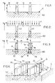
- the figures 1-3 are sectional views of an integrated electronic circuit being made from a substantially planar substrate in a cutting plane which is perpendicular to the surface of the substrate.
- N denotes a direction perpendicular to the surface of the substrate, facing outwardly thereof. This direction is repeated in all the figures.
- the terms "on”, “under”, “lower” and “higher” are used for the circuit with reference to this orientation.
- a bulk substrate of integrated electronic circuit is composed of monocrystalline silicon, weakly doped or undoped. It is referenced 100 and has an upper surface S which is flat. A portion of this substrate which is adjacent to the surface S is used to form at least one, for example two finFET transistors in proximity to each other. This portion is called the active portion of the substrate.
- a mask M is formed on the surface S of the substrate 100, which has openings at the locations of the transistors to be produced.
- these openings are denoted O1 and O2. They have widths w which can be between 10 and 100 nm (nanometer) approximately.
- M mask may be silica (SiO 2 ) chemically deposited from gaseous precursors, for example, and have a thickness e which is between 10 and 100 nm in the direction N, preferably between 60 and 100 nm.
- the O1 and O2 openings may be formed using a lithographic resin mask and a directional etching method of the M mask, for example.
- Doppler particles are then implanted in portions of the active portion of the substrate 100 which are discovered in the openings O1 and O2.
- the doping particles are accelerated in the form of a beam F which is directed against the upper surface of the circuit, parallel to the direction N and in the opposite direction to it ( figure 2 ).
- the surface of the circuit is scanned with the beam F.
- the doping particles are thus implanted in the substrate 100, selectively within portions of the active portion which are referenced 10 and 20 and which are bounded by the edges of the openings O1 and O2 parallel to the surface S of the substrate 100.
- the depth of the parts 10 and 20, in the direction N, and the concentration of the doping particles in these parts are fixed by the energy and intensity of the beam F.
- the mask M is kept on the circuit.
- Deposition of crystalline semiconductor material is then performed under conditions that are adapted to obtain epitaxial growth of material that is formed from crystalline semiconductor material already present in the circuit and which is discovered.
- monocrystalline portions 11 and 12 are formed ( figure 3 ), which are for example silicon or silicon alloy and germanium, or silicon incorporating carbon.
- the composition of the portions 11 and 12 may be selected in particular to obtain a constituent material thereof that is prestressed.
- the formation of the portions 11 and 12 is stopped before they protrude above the mask M. In this way, the portions 11 and 12 have side sides parallel to the direction N which are plane to the apices of these portions. portions.
- each doped portion 10, 20 of the substrate has two opposite boundaries which are respectively aligned with two opposite sides of portion 11, 12 corresponding, in the direction N.
- the lateral limits of the doped portion 10 of the active zone of the substrate 100 are referenced 10a and 10b, and the sides of the portion 11 are referenced 11a and 11b.
- the portions 11 and 12 each have the width w, which is common with the doped portions 10 and 20 of the substrate. Since the portions 11 and 12 have a height h in the direction N which is preferably greater than the width w, the portions 11 and 12 are called narrow portions ("fins" in English).
- Portions 11 and 12 may be doped either directly during their epitaxial formation or after their formation in a separate step.
- the doping of the portions 11 and 12 is selected to be of the opposite type to that of the portions 10 and 20 of the active portion of the substrate 100.
- the parts 10 and 20 have a p-type doping, which can be obtained with boron (B), and portions 11 and 12 have n-type doping, which can be obtained with phosphorus (P) or arsenic (As). Electrical junctions, which are noted J1 and J2 on the figure 3 , are thus obtained at the contact interfaces of the portions 11 and 12 respectively with the parts 10 and 20.
- the completion of the finFET transistors can then be continued in a manner known per se, from the narrow portions 11 and 12 ( figure 4 ).
- M mask is removed, for example using a method of selective etching of silica.
- the portions 11 and 12 can then be thermally oxidized on the surface, in order to create on them thin layers of grid insulation (not shown).
- Portions of grids 21 and 22, which may be of polysilicon (poly-Si), are then formed on top of each portion 11 and 12.
- Grid portions 21 and 22 may be in the form of bridges which overlap respectively from above. narrow portions 11 and 12, being electrically insulated from them.
- Middle portions of the portions 11 and 12, which are respectively in contact with the grid portions 21 and 22 by the internal surfaces thereof, constitute the channels of the corresponding finFET transistors.
- each narrow portion 11, 12 may have ends protruding from each side of the grid portion 21, 22 corresponding.
- each narrow portion comprises, in addition to the channel, source and drain zones of the finFET transistor obtained.
- the narrow portion 11 constitutes the channel 1 and the source areas 2 and drain 3 of the same transistor.
- the source 2 and drain 3 zones are thus located in the continuous extension of the channel 1 on each side thereof.
- L denotes the conduction direction of this transistor, which is parallel to the surface S.
- the electrical junction J1 also extends continuously under the channel 1 and under the source 2 and drain 3 zones.
- the two transistors that are obtained are denoted T1 and T2.
- the portion 11 which forms the channel and the source and drain regions of the transistor T1 is isolated from the substrate 100 by the electrical junction J1, when the portion 11 is brought to an electrical potential which is greater than that of the substrate 100.
- the portion 12 which forms the channel and the source and drain regions of the transistor T2 is isolated from the substrate 100 by the electrical junction J2.
- the following paths of leakage currents are cut by the electrical junctions J1 and J2: the path C1 which connects, for each transistor T1, T2 through the substrate 100, the source and drain zones of the same transistor, the path C2 which connects the narrow portions 11 and 12 to each other through the substrate 100, and the path C3 which connects each narrow portion 11, 12 to a lower part of the substrate 100.
- Each transistor T1, T2 is therefore electrically isolated so as to effective, so that no leakage current via the substrate 100 disrupts its operation.
- an alternative embodiment of the invention may consist in forming the material of the narrow portion with an initial composition which already comprises its electrical doping. Electrical isolation junction of the narrow portion is then directly obtained at the time of the epitaxial formation of this narrow portion.
- epitaxial growth methods of doped semiconductor materials are known to those skilled in the art, which lead directly to appropriate doping levels to form an electrical insulation junction. Once the junction is performed, the epitaxial growth process of the narrow portion can be continued under conditions that result in lower intrinsic doping.
Abstract
Description
La présente invention concerne un procédé de réalisation d'un transistor à effet de champ (FET) de type finFET, ainsi qu'un transistor du type obtenu par un tel procédé.The present invention relates to a method for producing a finFET type field effect transistor (FET), as well as a transistor of the type obtained by such a method.
De nombreux circuits électroniques intégrés sont réalisés à titre expérimental, qui incorporent un ou plusieurs transistors à effet de champ de type finFET. Un tel transistor comprend un canal qui est orienté pour conduire un courant électrique parallèlement à la surface d'un substrat du circuit, et qui possède une section allongée perpendiculairement à cette surface du substrat. Une telle structure de transistor à effet de champ est adaptée pour former une grille qui est disposée de part est d'autre de grands côtés du canal, pour permettre un bon contrôle de l'état de conduction du transistor. Elle est aussi adaptée pour fabriquer un transistor à canaux multiples, dans lequel des canaux voisins sont séparés par une portion intermédiaire de grille.Numerous integrated electronic circuits are realized on an experimental basis, which incorporate one or more finFET field effect transistors. Such a transistor comprises a channel which is oriented to conduct an electric current parallel to the surface of a circuit substrate, and which has an elongate section perpendicular to this surface of the substrate. Such a field effect transistor structure is adapted to form a gate which is disposed on both sides of the long sides of the channel, to allow good control of the conduction state of the transistor. It is also suitable for manufacturing a multi-channel transistor, in which neighboring channels are separated by an intermediate gate portion.
Un transistor finFET est élaboré à partir d'au moins une portion étroite («fin» en anglais) de matériau semiconducteur qui est destinée à former le canal du transistor, et éventuellement aussi les zones de source et de drain de celui-ci. Cette portion étroite est définie par un masque qui est formé sur le substrat de silicium monocristallin à l'emplacement de celle-ci. Le matériau du substrat est alors gravé de façon directionnelle en dehors du masque, sur une hauteur déterminée qui est plus grande que la largeur du masque, de sorte que la portion étroite reste sous le masque, en étant constituée du matériau initial du substrat.A finFET transistor is produced from at least one narrow portion ("end" in English) of semiconductor material which is intended to form the channel of the transistor, and possibly also the source and drain zones thereof. This narrow portion is defined by a mask that is formed on the monocrystalline silicon substrate at the location thereof. The substrate material is then directionally etched outside the mask, at a given height which is larger than the width of the mask, so that the narrow portion remains under the mask, consisting of the initial material of the substrate.
Mais la portion étroite de matériau semiconducteur qui est ainsi obtenue, et qui comprend le canal du transistor final, n'est pas isolée électriquement par rapport à la portion active du substrat du circuit, elle-même aussi en matériau semiconducteur cristallin. Il en résulte trois types de courants de fuite. Un premier courant de fuite peut circuler entre les zones de source et de drain du transistor finFET, via la portion active du substrat qui est située en dessous du canal. Ce premier courant de fuite, interne à chaque transistor, n'est pas contrôlé par la grille de celui-ci. Par ailleurs, le canal du transistor finFET est aussi en contact électrique avec les canaux d'autres transistors du même type via le substrat, ce qui produit des seconds courants de fuite qui circule entre des transistors différents, i.e. des courants de fuite inter-transistors. Enfin, un troisième courant de fuite peut aussi apparaître entre le canal de chaque transistor finFET et une partie inférieure du substrat lorsque celle-ci est connectée à une borne de potentiel électrique de référence.But the narrow portion of semiconductor material that is thus obtained, and which comprises the channel of the final transistor, is not electrically insulated from the active portion of the circuit substrate, itself also crystalline semiconductor material. This results in three types of leakage currents. A first leakage current can flow between the source and drain regions of the finFET transistor, via the active portion of the substrate which is located in below the channel. This first leakage current, internal to each transistor, is not controlled by the gate thereof. Moreover, the channel of the finFET transistor is also in electrical contact with the channels of other transistors of the same type via the substrate, which produces second leakage currents which circulates between different transistors, ie inter-transistor leakage currents. . Finally, a third leakage current may also appear between the channel of each finFET transistor and a lower portion of the substrate when it is connected to a reference electrical potential terminal.
Pour éviter ces courants de fuite, il est connu de réaliser le transistor finFET sur un substrat de circuit électronique intégré de type SOI, pour «Silicon On lsolator». Un tel substrat comporte, sur une partie inférieure de celui-ci, une couche intermédiaire de matériau électriquement isolant qui est surmontée d'une couche cristalline de silicium. Le document
Il est aussi connu de réaliser une jonction électrique à proximité de la surface de contact entre la portion active du substrat et la portion étroite du canal. Une telle jonction électrique, lorsqu'elle est polarisée en inverse, isole électriquement le canal du transistor par rapport à la portion active du substrat.It is also known to provide an electrical junction near the contact surface between the active portion of the substrate and the narrow portion of the channel. Such an electrical junction, when reverse biased, electrically isolates the channel of the transistor from the active portion of the substrate.
Selon une première méthode qui est couramment utilisée pour réaliser une telle jonction électrique, la portion étroite est d'abord obtenue et dopée électriquement selon un premier type de dopage. Des particules dopantes d'un second type opposé au premier type de dopage sont alors implantées dans une partie inférieure de la portion étroite, en utilisant un faisceau d'implantation oblique qui est dirigé en biais vers la base de la portion étroite, à partir de chaque côté de celle-ci. L'implantation des particules dopantes dans les parties médiane et supérieure de la portion étroite doit être évitée, pour conserver l'efficacité électrique du premier dopage dans ces parties qui sont destinées à former le canal du transistor. Mais, malgré des précautions opératoires, des particules dopantes du second type de dopage sont aussi implantées involontairement dans le canal. Elles causent alors une réduction de la mobilité des porteurs électriques du canal, ainsi que des variations involontaires de la concentration effective de ces porteurs. Les caractéristiques de conduction électrique de transistors finFET qui sont réalisés de cette façon avec des paramètres opératoires identiques varient alors de façon incontrôlée, conduisant à une faible reproductibilité des circuits électroniques obtenus.According to a first method which is commonly used to make such an electrical junction, the narrow portion is first obtained and electrically doped according to a first type of doping. Doping particles of a second type opposite to the first type of doping are then implanted in a lower part of the narrow portion, using an oblique implantation beam which is directed obliquely towards the base of the narrow portion, starting from each side of it. The implantation of the doping particles in the middle and upper portions of the narrow portion must be avoided in order to maintain the electrical efficiency of the first doping in those parts which are intended to form the channel of the transistor. But, despite operative precautions, Doping particles of the second type of doping are also involuntarily implanted in the channel. They then cause a reduction in the mobility of the electrical carriers of the channel, as well as involuntary variations in the effective concentration of these carriers. The electrical conduction characteristics of finFET transistors which are made in this way with identical operating parameters then vary in an uncontrolled manner, leading to low reproducibility of the electronic circuits obtained.
Selon une seconde méthode, la portion étroite est encore obtenue et dopée électriquement dans un premier temps, en étant recouverte d'un masque. Des particules dopantes d'un type opposé à celles du dopage de la portion étroite sont ensuite implantées dans le substrat en dehors de la zone de la surface du substrat qui est occupée par la portion étroite et occultée par le masque. Les particules dopantes du substrat sont implantées au moyen d'un faisceau qui est dirigé perpendiculairement à la surface du substrat, pour éviter que certaines de ces particules ne pénètrent dans la portion étroite par les côtés latéraux de celle-ci, qui sont perpendiculaires à la surface du substrat. Une jonction électrique apparaît alors dans la partie active du substrat en dessous de la portion étroite, du fait d'une diffusion latérale des particules dopantes parallèlement à la surface du substrat, en dessous de la portion étroite.According to a second method, the narrow portion is still obtained and electrically doped at first, being covered with a mask. Doping particles of a type opposite to those of the doping of the narrow portion are then implanted in the substrate outside the area of the surface of the substrate which is occupied by the narrow portion and obscured by the mask. The doping particles of the substrate are implanted by means of a beam which is directed perpendicular to the surface of the substrate, to prevent some of these particles from entering the narrow portion by the lateral sides thereof, which are perpendicular to the substrate. surface of the substrate. An electrical junction then appears in the active part of the substrate below the narrow portion, due to lateral diffusion of the doping particles parallel to the surface of the substrate, below the narrow portion.
Mais cette seconde méthode présente les inconvénients suivants. Tout d'abord, les caractéristiques de la jonction électrique qui est ainsi obtenue dépendent fortement de la largeur de la portion étroite. Or cette largeur n'est pas toujours contrôlée avec précision. L'isolation électrique du canal du transistor présente alors des fluctuations incontrôlées entre des transistors finFET qui sont réalisés avec des paramètres opératoires identiques. En outre, à cause d'une divergence résiduelle du faisceau d'implantation des particules dopantes de la portion active du substrat, et/ou à cause d'une inclinaison involontaire des côtés latéraux de la portion étroite, des particules dopantes destinées à la portion active du substrat sont aussi implantées dans la portion étroite. La mobilité et la concentration des porteurs électriques dans le canal présentent alors encore des variations involontaires.But this second method has the following drawbacks. First of all, the characteristics of the electrical junction which is thus obtained depend strongly on the width of the narrow portion. But this width is not always precisely controlled. The electrical isolation of the transistor channel then exhibits uncontrolled fluctuations between finFET transistors which are made with identical operating parameters. Moreover, because of a residual divergence of the implantation beam of the doping particles of the active portion of the substrate, and / or because of an involuntary inclination of the lateral sides of the narrow portion, doping particles intended for the portion active substrate are also implanted in the narrow portion. The mobility and the concentration of the electric carriers in the channel then still have involuntary variations.
En outre, dans les deux méthodes connues qui ont été rappelées ci-dessus, l'implantation involontaire de particules dopantes destinées à la portion active du substrat dans les côtés latéraux de la portion étroite provoque un facetage de ces côtés. Un tel facetage empêche d'obtenir une interface entre le canal et la couche d'isolation de grille du transistor finFET qui présente une faible rugosité.In addition, in the two known methods which have been recalled above, the involuntary implantation of doping particles intended for the active portion of the substrate in the lateral sides of the narrow portion causes a faceting of these sides. Such faceting prevents an interface between the channel and the gate insulation layer of the finFET transistor having a low roughness.
Un but de la présente invention consiste donc à réaliser un transistor finFET d'une façon qui ne présente pas les inconvénients cités ci-dessus.An object of the present invention is therefore to provide a finFET transistor in a manner that does not have the disadvantages mentioned above.
En particulier, l'invention a pour but de proposer un procédé de réalisation d'un transistor finFET qui soit compatible avec l'utilisation d'un substrat massif («bulk») de circuit électronique intégré, tout en aboutissant à un transistor qui est isolé électriquement par rapport au substrat.In particular, the aim of the invention is to propose a method for producing a finFET transistor that is compatible with the use of a bulk substrate of integrated electronic circuit, while at the same time leading to a transistor that is electrically isolated from the substrate.
Pour cela, l'invention propose un procédé de réalisation d'un transistor à effet de champ de type finFET sur un substrat de circuit électronique intégré, qui comprend les étapes suivantes :
- /1/ former un masque sur une surface du substrat, avec une ouverture du masque qui est située au dessus d'une partie exposée d'une portion active de ce substrat en matériau semiconducteur cristallin; et
- /2/ former par croissance épitaxique à partir de la partie de portion active qui est exposée dans l'ouverture du masque, une portion étroite de matériau semiconducteur cristallin qui comprend au moins le canal du transistor.
- / 1 / forming a mask on a surface of the substrate, with a mask opening which is located above an exposed portion of an active portion of said crystalline semiconductor material substrate; and
- / 2 / epitaxially growing from the active portion portion that is exposed in the mask aperture, a narrow portion of crystalline semiconductor material that comprises at least the transistor channel.
Le procédé de l'invention comprend en outre l'étape suivante, qui est effectuée entre les étapes /1/ et /2/ précédentes:
- réaliser une implantation de particules dopantes par l'ouverture du masque dans la partie exposée de la portion active du substrat, de façon à créer dans celle-ci un dopage électrique d'un second type opposé à un premier type de dopage utilisé pour le canal du transistor.
- performing implantation of doping particles by opening the mask in the exposed portion of the active portion of the substrate, so as to create therein an electrical doping of a second type opposite to a first type of doping used for the channel of the transistor.
Conformément à la structure de transistor finFET, le canal qui est constitué d'une partie de la portion étroite de matériau semiconducteur cristallin possède une direction de conduction électrique qui est parallèle à la surface du substrat. Il possède aussi une section perpendiculaire à cette direction de conduction qui est allongée perpendiculairement à la surface du substrat.In accordance with the finFET transistor structure, the channel which consists of a portion of the narrow portion of crystalline semiconductor material has an electrical conduction direction which is parallel to the surface of the crystalline semiconductor material. substrate. It also has a section perpendicular to this direction of conduction which is elongated perpendicular to the surface of the substrate.
Ainsi, selon une première caractéristique de l'invention, la portion étroite qui forme le canal est constituée d'un matériau qui est déposé sur le substrat à l'étape /2/, et qui n'appartient donc pas initialement au substrat.Thus, according to a first characteristic of the invention, the narrow portion that forms the channel consists of a material that is deposited on the substrate in step / 2 /, and therefore does not initially belong to the substrate.
Selon une seconde caractéristique de l'invention, l'implantation de particules dopantes dans la portion active du substrat est effectuée avant que la portion étroite soit formée. De cette façon, la portion étroite, et par conséquent le canal du transistor finFET qui est réalisé, est complètement dépourvue de particules destinées à doper la portion active du substrat. Les caractéristiques électriques du canal ne sont donc pas perturbées par de telles particules de type opposé au dopage de la portion étroite. En particulier, la mobilité et la concentration des porteurs électriques du canal ne sont pas réduites involontairement. En outre, la rugosité des côtés latéraux de la portion étroite n'est pas augmentée par un facetage involontaire.According to a second characteristic of the invention, the implantation of doping particles in the active portion of the substrate is carried out before the narrow portion is formed. In this way, the narrow portion, and therefore the channel of the finFET transistor that is made, is completely devoid of particles for doping the active portion of the substrate. The electrical characteristics of the channel are not disturbed by such particles of the opposite type to the doping of the narrow portion. In particular, the mobility and the concentration of the electrical carriers of the channel are not reduced involuntarily. In addition, the roughness of the lateral sides of the narrow portion is not increased by involuntary faceting.
Dans le transistor finFET qui est obtenu, le canal et la portion active du substrat ont des dopages opposés et sont directement en contact l'un avec l'autre. Une jonction électrique est ainsi formée pour isoler électriquement le canal par rapport à la partie inférieure du substrat, ainsi que par rapport à d'autres canaux de transistors qui sont portés par le même substrat. Cette jonction électrique présente en outre des caractéristiques qui sont reproductibles. Notamment, ces caractéristiques sont indépendantes de la largeur de la portion étroite mesurée parallèlement à la surface du substrat.In the finFET transistor that is obtained, the channel and the active portion of the substrate have opposite dopings and are in direct contact with each other. An electrical junction is thus formed to electrically insulate the channel relative to the lower part of the substrate, as well as with respect to other channels of transistors that are carried by the same substrate. This electrical junction also has characteristics that are reproducible. In particular, these characteristics are independent of the width of the narrow portion measured parallel to the surface of the substrate.
Par ailleurs, le même masque est utilisé pour limiter transversalement l'implantation des particules dopantes dans la portion active du substrat et pour définir les dimensions de la portion étroite. Il est résulte que la jonction électrique d'isolation du canal est limitée à la zone du substrat qui est occupée par la portion étroite. De cette façon, la conductivité électrique du substrat reste très faible en dehors de la zone qui est occupée par la portion étroite, ce qui contribue à réduire encore plus d'éventuels courants de fuite qui circuleraient dans le substrat.Furthermore, the same mask is used to transversely limit the implantation of the doping particles in the active portion of the substrate and to define the dimensions of the narrow portion. As a result, the isolation electrical junction of the channel is limited to the area of the substrate that is occupied by the narrow portion. In this way, the electrical conductivity of the substrate remains very low outside the zone which is occupied by the narrow portion, which contributes to reducing even more possible leakage currents flowing in the substrate.
Un premier avantage d'un procédé selon l'invention résulte de la formation de la portion étroite par croissance épitaxique à partir du substrat. En effet, une telle méthode de formation de matériau sur un circuit électronique intégré est bien maîtrisée actuellement et permet d'obtenir des rendements de production élevés.A first advantage of a method according to the invention results from the formation of the narrow portion by epitaxial growth from the substrate. Indeed, such a method of forming material on an integrated electronic circuit is well controlled at present and allows to obtain high production yields.
Un second avantage provient du type de l'isolation électrique qui est créée entre chaque transistor et le substrat. Cette isolation est similaire à celle de la technologie MOS (pour «Metal Oxide Semiconductor» en anglais) avec substrat massif («bulk»). Les acquis de cette technologie peuvent donc être repris en partie pour un circuit qui est réalisé conformément à l'invention.A second advantage comes from the type of electrical isolation that is created between each transistor and the substrate. This insulation is similar to that of the MOS technology (for "Metal Oxide Semiconductor" in English) with massive substrate ("bulk"). The achievements of this technology can therefore be taken over in part for a circuit that is realized in accordance with the invention.
Selon un perfectionnement de l'invention, la portion étroite peut comprendre, en plus du canal, des zones de source et de drain du transistor. Celles-ci sont alors isolées électriquement par rapport à la portion active du substrat de la même façon que le canal, de sorte qu'aucun courant de fuite ne peut circuler dans le substrat entre la source et le drain du transistor.According to an improvement of the invention, the narrow portion may comprise, in addition to the channel, source and drain zones of the transistor. These are then electrically isolated from the active portion of the substrate in the same way as the channel, so that no leakage current can flow in the substrate between the source and the drain of the transistor.
L'invention propose aussi un circuit électronique intégré qui incorpore un transistor à effet de champ de type finFET, et qui comprend :
- un substrat ayant une portion active en matériau semiconducteur cristallin ; et
- une portion étroite en matériau semiconducteur cristallin, comprenant le canal du transistor et ayant un dopage électrique d'un premier type, et étant en contact avec la portion active du substrat au niveau d'une surface de ce substrat.
- a substrate having an active portion of crystalline semiconductor material; and
- a narrow portion of crystalline semiconductor material, comprising the transistor channel and having an electrical doping of a first type, and being in contact with the active portion of the substrate at a surface of this substrate.
Dans un tel circuit selon l'invention, une partie de la portion active du substrat qui est en contact à la portion étroite est dopée selon un second type de dopage opposé au premier type. En outre, cette partie dopée de la portion active possède une limite de dopage qui est alignée par rapport à un côté de la portion étroite, perpendiculairement à la surface du substrat.In such a circuit according to the invention, a portion of the active portion of the substrate which is in contact with the narrow portion is doped according to a second type of doping opposite to the first type. In addition, this doped part of the active portion has a doping limit which is aligned with respect to one side of the narrow portion, perpendicular to the surface of the substrate.
Un tel circuit à transistor finFET peut notamment être réalisé en utilisant un procédé tel que décrit précédemment. Dans ce cas, l'alignement de la limite de dopage de la partie dopée de la partie de portion active du substrat résulte de l'utilisation du même masque pour doper sélectivement la partie de portion active et pour définir les dimensions transversales de la portion étroite parallèlement à la surface du substrat.Such a finFET transistor circuit can in particular be implemented using a method as described above. In this case, the alignment of the doping limit of the doped portion of the active portion portion of the substrate results from the use of the same mask to selectively dope the portion of the substrate. active portion and to define the transverse dimensions of the narrow portion parallel to the surface of the substrate.
D'autres particularités et avantages de la présente invention apparaîtront dans la description ci-après d'un exemple de mise en oeuvre non limitatif, en référence aux
Pour raison de clarté, les dimensions des différents éléments qui sont représentés dans ces figures ne sont pas en proportion avec des dimensions ni avec des rapports de dimensions réels. Les
Dans ce qui suit, les étapes élémentaires du procédé de réalisation d'un circuit électronique intégré qui sont connues de l'Homme du métier ne sont pas décrites en détail. On s'attache seulement à décrire une succession d'étapes élémentaires qui permet de reproduire l'invention.In the following, the basic steps of the method of producing an integrated electronic circuit which are known to those skilled in the art are not described in detail. It is only necessary to describe a succession of elementary steps which makes it possible to reproduce the invention.
Conformément à la
On forme sur la surface S du substrat 100 un masque M, qui présente des ouvertures aux emplacements des transistors à réaliser. Sur la
On réalise alors une implantation de particules dopantes dans des parties de la portion active du substrat 100 qui sont découvertes dans les ouvertures O1 et O2. Pour cela, les particules dopantes sont accélérées sous forme d'un faisceau F qui est dirigé contre la surface supérieure du circuit, parallèlement à la direction N et en sens opposé à celle-ci (
Après l'implantation des parties 10 et 20, le masque M est conservé sur le circuit. Un dépôt de matériau semiconducteur cristallin est ensuite effectué, dans des conditions qui sont adaptées pour obtenir une croissance épitaxique du matériau qui est formé à partir de matériau semiconducteur cristallin déjà présent dans le circuit et qui est découvert. De cette façon, des portions monocristallines 11 et 12 sont formées (
Du fait de l'utilisation du masque M pour effectuer l'implantation sélective des parties 10 et 20 du substrat 100 puis pour former les portions 11 et 12, chaque partie dopée 10, 20 du substrat possède deux limites opposées qui sont alignées respectivement avec deux côtés opposés de la portion 11, 12 correspondante, selon la direction N. Sur la
Les portions 11 et 12 peuvent être dopées soit directement pendant leur formation épitaxique, soit après leur formation lors d'une étape distincte. Le dopage des portions 11 et 12 est sélectionné pour être de type opposé à celui des parties 10 et 20 de la portion active du substrat 100. Par exemple, les parties 10 et 20 ont un dopage de type p, qui peut être obtenu avec du bore (B), et les portions 11 et 12 ont un dopage de type n, qui peut être obtenu avec du phosphore (P) ou de l'arsenic (As). Des jonctions électriques, qui sont notées J1 et J2 sur la
La réalisation des transistors finFET peut alors être poursuivie d'une façon qui est connue en soi, à partir des portions étroites 11 et 12 (
De préférence, chaque portion étroite 11, 12 peut posséder des extrémités qui dépassent de chaque côté de la portion de grille 21, 22 correspondante. Dans ce cas, chaque portion étroite comprend, en plus du canal, des zones de source et de drain du transistor finFET obtenu. Sur la
Les deux transistors qui sont obtenus sont notés T1 et T2. La portion 11 qui forme le canal et les zones de source et de drain du transistor T1 est isolée du substrat 100 par la jonction électrique J1, lorsque la portion 11 est portée à un potentiel électrique qui est supérieur à celui du substrat 100. De même, la portion 12 qui forme le canal et les zones de source et de drain du transistor T2 est isolée du substrat 100 par la jonction électrique J2. De cette façon, les chemins de courants de fuite suivants sont coupés par les jonctions électriques J1 et J2 : le chemin C1 qui relie, pour chaque transistor T1, T2 à travers le substrat 100, les zones de source et de drain du même transistor, le chemin C2 qui relie les portions étroites 11 et 12 entre elles à travers le substrat 100, et le chemin C3 qui relie chaque portion étroite 11, 12 à une partie inférieure du substrat 100. Chaque transistor T1, T2 est donc isolé électriquement de façon efficace, de sorte qu'aucun courant de fuite via le substrat 100 ne perturbe son fonctionnement.The two transistors that are obtained are denoted T1 and T2. The portion 11 which forms the channel and the source and drain regions of the transistor T1 is isolated from the
Il est entendu que de nombreuses adaptations de l'invention peuvent être introduites par rapport à la mise en oeuvre qui a été décrite en détail ci-dessus, tout en conservant certains au moins des avantages de celle-ci. En particulier, les dimensions et les matériaux qui ont été cités peuvent être modifiés. De plus, l'invention peut être combinée avec des méthodes déjà connues pour réduire l'épaisseur w des portions étroites de transistors finFET.It is understood that many adaptations of the invention may be introduced with respect to the implementation which has been described in detail above, while retaining at least some of the advantages thereof. In particular, the dimensions and materials that have been quoted can be modified. In addition, the invention can be combined with methods already known for reducing the thickness w of narrow portions of finFET transistors.
Enfin, un mode alternatif de mise en oeuvre de l'invention peut consister à former le matériau de la portion étroite avec une composition initiale qui comprend déjà son dopage électrique. La jonction électrique d'isolation de la portion étroite est alors directement obtenue au moment de la formation épitaxique de cette portion étroite. En effet, des procédés de croissance épitaxique de matériaux semiconducteurs dopés sont connus de l'Homme du métier, qui aboutissent directement à des niveaux de dopage appropriés pour former une jonction d'isolation électrique. Une fois que la jonction est réalisée, le procédé de croissance épitaxique de la portion étroite peut être poursuivi dans des conditions qui aboutissent à un dopage intrinsèque plus faible.Finally, an alternative embodiment of the invention may consist in forming the material of the narrow portion with an initial composition which already comprises its electrical doping. Electrical isolation junction of the narrow portion is then directly obtained at the time of the epitaxial formation of this narrow portion. Indeed, epitaxial growth methods of doped semiconductor materials are known to those skilled in the art, which lead directly to appropriate doping levels to form an electrical insulation junction. Once the junction is performed, the epitaxial growth process of the narrow portion can be continued under conditions that result in lower intrinsic doping.
Claims (7)
le transistor comprenant un canal (1) constitué d'un matériau semiconducteur dopé électriquement selon un premier type de dopage,
le canal ayant une direction de conduction électrique (L) parallèle à une surface (S) du substrat et une section perpendiculaire à ladite direction de conduction, ladite section étant allongée perpendiculairement à la surface du substrat,
le substrat (100) ayant une portion active en matériau semiconducteur cristallin exposée initialement à la surface (S) dudit substrat,
le procédé comprenant les étapes suivantes :
the transistor comprising a channel (1) made of a semiconductor material electrically doped according to a first type of doping,
the channel having an electrical conduction direction (L) parallel to a surface (S) of the substrate and a section perpendicular to said conduction direction, said section being elongated perpendicular to the surface of the substrate,
the substrate (100) having an active portion of crystalline semiconductor material initially exposed on the surface (S) of said substrate,
the method comprising the following steps:
une partie (10) de la portion active du substrat qui est en contact avec la portion étroite (11) étant dopée électriquement selon un second type de dopage opposé audit premier type,
le circuit étant caractérisé en ce qu'au moins une limite de dopage de ladite partie dopée de la portion active (10) est alignée par rapport à un côté de la portion étroite (11), perpendiculairement à la surface du substrat.An integrated electronic circuit incorporating a finFET field effect transistor (T1) and comprising:
a portion (10) of the active portion of the substrate which is in contact with the narrow portion (11) being electrically doped according to a second type of doping opposite to said first type,
the circuit being characterized in that at least one boundary doping of said doped portion of the active portion (10) is aligned with one side of the narrow portion (11) perpendicular to the substrate surface.
Applications Claiming Priority (1)
| Application Number | Priority Date | Filing Date | Title |
|---|---|---|---|
| FR0704568A FR2918211A1 (en) | 2007-06-26 | 2007-06-26 | FIELD-EFFECT FIELD EFFECT TRANSISTOR ISOLATED FROM THE SUBSTRATE |
Publications (2)
| Publication Number | Publication Date |
|---|---|
| EP2009682A1 true EP2009682A1 (en) | 2008-12-31 |
| EP2009682B1 EP2009682B1 (en) | 2011-04-06 |
Family
ID=38959679
Family Applications (1)
| Application Number | Title | Priority Date | Filing Date |
|---|---|---|---|
| EP08158608A Expired - Fee Related EP2009682B1 (en) | 2007-06-26 | 2008-06-19 | FinFET field-effect transistor isolated from the substrate |
Country Status (4)
| Country | Link |
|---|---|
| US (2) | US7781315B2 (en) |
| EP (1) | EP2009682B1 (en) |
| DE (1) | DE602008005959D1 (en) |
| FR (1) | FR2918211A1 (en) |
Families Citing this family (21)
| Publication number | Priority date | Publication date | Assignee | Title |
|---|---|---|---|---|
| US8507948B2 (en) * | 2010-12-23 | 2013-08-13 | Intel Corporation | Junctionless accumulation-mode devices on prominent architectures, and methods of making same |
| US8420459B1 (en) | 2011-10-20 | 2013-04-16 | International Business Machines Corporation | Bulk fin-field effect transistors with well defined isolation |
| CN103187286B (en) * | 2011-12-29 | 2016-08-10 | 中芯国际集成电路制造(上海)有限公司 | The manufacture method of fin formula field effect transistor |
| US9236267B2 (en) * | 2012-02-09 | 2016-01-12 | Taiwan Semiconductor Manufacturing Company, Ltd. | Cut-mask patterning process for fin-like field effect transistor (FinFET) device |
| KR20130096953A (en) * | 2012-02-23 | 2013-09-02 | 삼성전자주식회사 | Method for manufacturing semiconductor device |
| US11037923B2 (en) * | 2012-06-29 | 2021-06-15 | Intel Corporation | Through gate fin isolation |
| US8946035B2 (en) | 2012-09-27 | 2015-02-03 | Taiwan Semiconductor Manufacturing Co., Ltd. | Replacement channels for semiconductor devices and methods for forming the same using dopant concentration boost |
| US9082853B2 (en) | 2012-10-31 | 2015-07-14 | International Business Machines Corporation | Bulk finFET with punchthrough stopper region and method of fabrication |
| KR101983633B1 (en) | 2012-11-30 | 2019-05-29 | 삼성전자 주식회사 | Semiconductor device and fabricated method thereof |
| US9006055B2 (en) * | 2013-01-30 | 2015-04-14 | Globalfoundries Singapore Pte. Ltd. | High voltage FINFET structure |
| CN104078332A (en) * | 2013-03-26 | 2014-10-01 | 中国科学院微电子研究所 | Manufacturing method of fin |
| US8975168B2 (en) | 2013-05-28 | 2015-03-10 | Stmicroelectronics, Inc. | Method for the formation of fin structures for FinFET devices |
| US9793378B2 (en) | 2013-05-31 | 2017-10-17 | Stmicroelectronics, Inc. | Fin field effect transistor device with reduced overlap capacitance and enhanced mechanical stability |
| US20140374807A1 (en) * | 2013-06-19 | 2014-12-25 | International Business Machines Corporation | METHOD OF DEVICE ISOLATION IN CLADDING Si THROUGH IN SITU DOPING |
| US9000498B2 (en) * | 2013-06-28 | 2015-04-07 | Stmicroelectronics, Inc. | FinFET with multiple concentration percentages |
| US9006077B2 (en) * | 2013-08-21 | 2015-04-14 | GlobalFoundries, Inc. | Gate length independent silicon-on-nothing (SON) scheme for bulk FinFETs |
| US9418902B2 (en) | 2013-10-10 | 2016-08-16 | Globalfoundries Inc. | Forming isolated fins from a substrate |
| US9496257B2 (en) | 2014-06-30 | 2016-11-15 | International Business Machines Corporation | Removal of semiconductor growth defects |
| US20160005849A1 (en) * | 2014-07-01 | 2016-01-07 | Qualcomm Incorporated | Method and apparatus for 3d concurrent multiple parallel 2d quantum wells |
| US10276718B2 (en) * | 2017-08-31 | 2019-04-30 | Taiwan Semiconductor Manufacturing Co., Ltd. | FinFET having a relaxation prevention anchor |
| US11257932B2 (en) * | 2020-01-30 | 2022-02-22 | Taiwan Semiconductor Manufacturing Co., Ltd. | Fin field effect transistor device structure and method for forming the same |
Citations (5)
| Publication number | Priority date | Publication date | Assignee | Title |
|---|---|---|---|---|
| US20020011612A1 (en) * | 2000-07-31 | 2002-01-31 | Kabushiki Kaisha Toshiba | Semiconductor device and method for manufacturing the same |
| US6645797B1 (en) | 2002-12-06 | 2003-11-11 | Advanced Micro Devices, Inc. | Method for forming fins in a FinFET device using sacrificial carbon layer |
| US20050156202A1 (en) * | 2004-01-17 | 2005-07-21 | Hwa-Sung Rhee | At least penta-sided-channel type of FinFET transistor |
| JP2006237376A (en) * | 2005-02-25 | 2006-09-07 | Toshiba Corp | Semiconductor device and manufacturing method thereof |
| US20070102763A1 (en) * | 2003-09-24 | 2007-05-10 | Yee-Chia Yeo | Multiple-gate transistors formed on bulk substrates |
Family Cites Families (2)
| Publication number | Priority date | Publication date | Assignee | Title |
|---|---|---|---|---|
| US7009250B1 (en) * | 2004-08-20 | 2006-03-07 | Micron Technology, Inc. | FinFET device with reduced DIBL |
| US20060252191A1 (en) * | 2005-05-03 | 2006-11-09 | Advanced Micro Devices, Inc. | Methodology for deposition of doped SEG for raised source/drain regions |
-
2007
- 2007-06-26 FR FR0704568A patent/FR2918211A1/en not_active Withdrawn
-
2008
- 2008-06-19 DE DE602008005959T patent/DE602008005959D1/en active Active
- 2008-06-19 EP EP08158608A patent/EP2009682B1/en not_active Expired - Fee Related
- 2008-06-25 US US12/146,166 patent/US7781315B2/en active Active
-
2010
- 2010-07-15 US US12/837,318 patent/US7960734B2/en active Active
Patent Citations (5)
| Publication number | Priority date | Publication date | Assignee | Title |
|---|---|---|---|---|
| US20020011612A1 (en) * | 2000-07-31 | 2002-01-31 | Kabushiki Kaisha Toshiba | Semiconductor device and method for manufacturing the same |
| US6645797B1 (en) | 2002-12-06 | 2003-11-11 | Advanced Micro Devices, Inc. | Method for forming fins in a FinFET device using sacrificial carbon layer |
| US20070102763A1 (en) * | 2003-09-24 | 2007-05-10 | Yee-Chia Yeo | Multiple-gate transistors formed on bulk substrates |
| US20050156202A1 (en) * | 2004-01-17 | 2005-07-21 | Hwa-Sung Rhee | At least penta-sided-channel type of FinFET transistor |
| JP2006237376A (en) * | 2005-02-25 | 2006-09-07 | Toshiba Corp | Semiconductor device and manufacturing method thereof |
Also Published As
| Publication number | Publication date |
|---|---|
| US20090001463A1 (en) | 2009-01-01 |
| US7960734B2 (en) | 2011-06-14 |
| US7781315B2 (en) | 2010-08-24 |
| DE602008005959D1 (en) | 2011-05-19 |
| US20100276693A1 (en) | 2010-11-04 |
| EP2009682B1 (en) | 2011-04-06 |
| FR2918211A1 (en) | 2009-01-02 |
Similar Documents
| Publication | Publication Date | Title |
|---|---|---|
| EP2009682B1 (en) | FinFET field-effect transistor isolated from the substrate | |
| EP0420748B1 (en) | Process of fabricating a high-tension MIS integrated circuit | |
| EP0426251A1 (en) | Process for manufacturing a device having MIS transistors with an inverted T-shaped gate electrode | |
| FR2884052A1 (en) | Vertical impact ionization metal oxide semiconductor transistor for use as e.g. N-channel MOS transistor, has stack with semiconductor portions to form vertical PIN type diode, and gate, placed against stack, with thickness less than stack | |
| EP3012876B1 (en) | Method for manufacturing a low-noise photodiode | |
| FR2795554A1 (en) | Making silicon-on-nothing architecture for high-speed CMOS signal- and low voltage power devices, includes formation of internal passivated or insulated cavities in stacked semiconductor assemblies | |
| FR2649831A1 (en) | SOI-MOS DEVICE HAVING A CONDUCTIVE LATERAL WALL STRUCTURE AND METHOD FOR MANUFACTURING THE SAME | |
| EP3502049B1 (en) | Method for manufacturing a semiconductor device comprising one or more nanostructures | |
| WO2018100262A1 (en) | Heterojunction transistor with vertical structure | |
| EP3503175A1 (en) | Method for producing a semiconductor substrate comprising at least one portion of semiconductor subjected to compressive strain | |
| EP0577498B1 (en) | Vertical JFET transistor having an optimized operation and process for fabricating the same | |
| EP3550622B1 (en) | Integrated circuit with bipolar transistors | |
| EP3442027B1 (en) | Method for forming doped extension regions in a structure having stacked nanowires | |
| FR2819342A1 (en) | Planar heterojunction bipolar transistor | |
| FR3067516A1 (en) | IMPLEMENTING SEMICONDUCTOR REGIONS IN AN ELECTRONIC CHIP | |
| EP1507286A2 (en) | Formation process under a thin layer of a first material from portions of another material and/or from vacuum gaps | |
| FR3089213A1 (en) | Method for manufacturing an electronic component with multiple quantum islands | |
| FR2858877A1 (en) | BIPOLAR TRANSISTOR WITH HETEROJUNCTION | |
| FR2556882A1 (en) | FAST SEMICONDUCTOR COMPONENT, IN PARTICULAR DIODE PIN HIGH VOLTAGE | |
| FR3035265A1 (en) | METHOD FOR MANUFACTURING SOI TRANSISTORS FOR INCREASED INTEGRATION DENSITY | |
| EP3136429B1 (en) | Formation of ohmic contacts for a device comprising a region made of iii-v material and a region made of another semiconductor material | |
| EP0038239B1 (en) | Blockable diode and method of manufacturing the same | |
| FR2970813A1 (en) | FIELD EFFECT DEVICE PROVIDED WITH A LOCALIZED DOPING DIFFUSION BARRIER ZONE AND METHOD OF REALIZING THE SAME | |
| FR2764119A1 (en) | BIPOLAR TRANSISTOR WITH INSULATED GRID AND METHOD FOR THE PRODUCTION THEREOF | |
| EP1369909A1 (en) | Method of fabricating a MOS transistor with reduced gate length and integrated circuit comprising such transistor |
Legal Events
| Date | Code | Title | Description |
|---|---|---|---|
| PUAI | Public reference made under article 153(3) epc to a published international application that has entered the european phase |
Free format text: ORIGINAL CODE: 0009012 |
|
| AK | Designated contracting states |
Kind code of ref document: A1 Designated state(s): AT BE BG CH CY CZ DE DK EE ES FI FR GB GR HR HU IE IS IT LI LT LU LV MC MT NL NO PL PT RO SE SI SK TR |
|
| AX | Request for extension of the european patent |
Extension state: AL BA MK RS |
|
| 17P | Request for examination filed |
Effective date: 20090623 |
|
| RAP1 | Party data changed (applicant data changed or rights of an application transferred) |
Owner name: STMICROELECTRONICS (CROLLES 2) SAS Owner name: IMEC |
|
| 17Q | First examination report despatched |
Effective date: 20090715 |
|
| AKX | Designation fees paid |
Designated state(s): DE FR GB |
|
| GRAP | Despatch of communication of intention to grant a patent |
Free format text: ORIGINAL CODE: EPIDOSNIGR1 |
|
| GRAS | Grant fee paid |
Free format text: ORIGINAL CODE: EPIDOSNIGR3 |
|
| GRAA | (expected) grant |
Free format text: ORIGINAL CODE: 0009210 |
|
| AK | Designated contracting states |
Kind code of ref document: B1 Designated state(s): DE FR GB |
|
| REG | Reference to a national code |
Ref country code: GB Ref legal event code: FG4D Free format text: NOT ENGLISH |
|
| REF | Corresponds to: |
Ref document number: 602008005959 Country of ref document: DE Date of ref document: 20110519 Kind code of ref document: P |
|
| REG | Reference to a national code |
Ref country code: DE Ref legal event code: R096 Ref document number: 602008005959 Country of ref document: DE Effective date: 20110519 |
|
| PLBE | No opposition filed within time limit |
Free format text: ORIGINAL CODE: 0009261 |
|
| STAA | Information on the status of an ep patent application or granted ep patent |
Free format text: STATUS: NO OPPOSITION FILED WITHIN TIME LIMIT |
|
| 26N | No opposition filed |
Effective date: 20120110 |
|
| REG | Reference to a national code |
Ref country code: DE Ref legal event code: R097 Ref document number: 602008005959 Country of ref document: DE Effective date: 20120110 |
|
| PGFP | Annual fee paid to national office [announced via postgrant information from national office to epo] |
Ref country code: DE Payment date: 20120524 Year of fee payment: 5 |
|
| PGFP | Annual fee paid to national office [announced via postgrant information from national office to epo] |
Ref country code: FR Payment date: 20120705 Year of fee payment: 5 |
|
| GBPC | Gb: european patent ceased through non-payment of renewal fee |
Effective date: 20120619 |
|
| PG25 | Lapsed in a contracting state [announced via postgrant information from national office to epo] |
Ref country code: GB Free format text: LAPSE BECAUSE OF NON-PAYMENT OF DUE FEES Effective date: 20120619 |
|
| REG | Reference to a national code |
Ref country code: DE Ref legal event code: R119 Ref document number: 602008005959 Country of ref document: DE Effective date: 20140101 |
|
| REG | Reference to a national code |
Ref country code: FR Ref legal event code: ST Effective date: 20140228 |
|
| PG25 | Lapsed in a contracting state [announced via postgrant information from national office to epo] |
Ref country code: DE Free format text: LAPSE BECAUSE OF NON-PAYMENT OF DUE FEES Effective date: 20140101 |
|
| PG25 | Lapsed in a contracting state [announced via postgrant information from national office to epo] |
Ref country code: FR Free format text: LAPSE BECAUSE OF NON-PAYMENT OF DUE FEES Effective date: 20130701 |