EP1852848A1 - Method and apparatus for lossless encoding of a source signal using a lossy encoded data stream and a lossless extension data stream - Google Patents
Method and apparatus for lossless encoding of a source signal using a lossy encoded data stream and a lossless extension data stream Download PDFInfo
- Publication number
- EP1852848A1 EP1852848A1 EP06113576A EP06113576A EP1852848A1 EP 1852848 A1 EP1852848 A1 EP 1852848A1 EP 06113576 A EP06113576 A EP 06113576A EP 06113576 A EP06113576 A EP 06113576A EP 1852848 A1 EP1852848 A1 EP 1852848A1
- Authority
- EP
- European Patent Office
- Prior art keywords
- signal
- lossy
- lossless
- data stream
- encoded
- Prior art date
- Legal status (The legal status is an assumption and is not a legal conclusion. Google has not performed a legal analysis and makes no representation as to the accuracy of the status listed.)
- Withdrawn
Links
Images


Classifications
-
- H—ELECTRICITY
- H03—ELECTRONIC CIRCUITRY
- H03M—CODING; DECODING; CODE CONVERSION IN GENERAL
- H03M7/00—Conversion of a code where information is represented by a given sequence or number of digits to a code where the same, similar or subset of information is represented by a different sequence or number of digits
- H03M7/30—Compression; Expansion; Suppression of unnecessary data, e.g. redundancy reduction
-
- G—PHYSICS
- G10—MUSICAL INSTRUMENTS; ACOUSTICS
- G10L—SPEECH ANALYSIS OR SYNTHESIS; SPEECH RECOGNITION; SPEECH OR VOICE PROCESSING; SPEECH OR AUDIO CODING OR DECODING
- G10L19/00—Speech or audio signals analysis-synthesis techniques for redundancy reduction, e.g. in vocoders; Coding or decoding of speech or audio signals, using source filter models or psychoacoustic analysis
- G10L19/0017—Lossless audio signal coding; Perfect reconstruction of coded audio signal by transmission of coding error
-
- G—PHYSICS
- G10—MUSICAL INSTRUMENTS; ACOUSTICS
- G10L—SPEECH ANALYSIS OR SYNTHESIS; SPEECH RECOGNITION; SPEECH OR VOICE PROCESSING; SPEECH OR AUDIO CODING OR DECODING
- G10L19/00—Speech or audio signals analysis-synthesis techniques for redundancy reduction, e.g. in vocoders; Coding or decoding of speech or audio signals, using source filter models or psychoacoustic analysis
- G10L19/04—Speech or audio signals analysis-synthesis techniques for redundancy reduction, e.g. in vocoders; Coding or decoding of speech or audio signals, using source filter models or psychoacoustic analysis using predictive techniques
- G10L19/16—Vocoder architecture
- G10L19/18—Vocoders using multiple modes
- G10L19/24—Variable rate codecs, e.g. for generating different qualities using a scalable representation such as hierarchical encoding or layered encoding
-
- G—PHYSICS
- G10—MUSICAL INSTRUMENTS; ACOUSTICS
- G10L—SPEECH ANALYSIS OR SYNTHESIS; SPEECH RECOGNITION; SPEECH OR VOICE PROCESSING; SPEECH OR AUDIO CODING OR DECODING
- G10L19/00—Speech or audio signals analysis-synthesis techniques for redundancy reduction, e.g. in vocoders; Coding or decoding of speech or audio signals, using source filter models or psychoacoustic analysis
- G10L19/02—Speech or audio signals analysis-synthesis techniques for redundancy reduction, e.g. in vocoders; Coding or decoding of speech or audio signals, using source filter models or psychoacoustic analysis using spectral analysis, e.g. transform vocoders or subband vocoders
Definitions
- the invention relates to a method and to an apparatus for lossless encoding of a source signal, using a lossy encoded data stream and a lossless extension data stream which together form a lossless encoded data stream for said source signal.
- Lossy perceptual audio coding data are enhanced by extension data that enable mathematically exact (lossless) reproduction of the original audio signal waveform.
- Fig. 1 The basic principle of lossless audio coding is depicted in Fig. 1.
- the digital PCM Audio signal samples are not independent to each other.
- a signal de-correlation 11 is used to reduce this dependency before entropy coding 12. This process needs to be reversible, to be able to restore the original signal.
- Known de-correlation techniques are using Linear Predictive Filtering (also known as Linear Predictive Coding LPC), integer filter-banks and lossy based approaches.
- a PCM audio input signal S PCM passes through a lossy encoder 21 to a lossy decoder 22 and as a lossy bit stream to a lossy decoder 25 in the decoding part (right side).
- Lossy encoding and decoding is used to de-correlate the signal.
- the output signal of decoder 22 is removed from the input signal S PCM in a subtractor 23, and the resulting difference signal passes through a lossless encoder 24 as an extension bit stream to a lossless decoder 27.
- the output signals of the decoders 25 and 27 are combined 26 so as to regain the original signal S PCM .
- the PCM audio input signal S PCM passes through an analysis filter bank 31 and a quantisation 32 of sub-band samples to a coding and bit stream packing 33.
- the quantisation is controlled by a perceptual model calculator 34 that receives signal S PCM and corresponding information from the analysis filter bank 31.
- the encoded lossy bit stream enters a means 35 for de-packing the bit stream, followed by means 36 for decoding the subband samples and by a synthesis filter bank 37 that outputs the decoded lossy PCM signal S Dec . Examples for lossy encoding and decoding are described in detail in the standard ISO/IEC 11172-3 (MPEG-1 Audio).
- EP-A-0905918 the amplitude of the error signal S Diff is used with a feedback loop to the quantisation stage of the lossy encoder part in order to control the quantisation in the lossy encoder and thus to generate a better de-correlation of the error signal S Diff .
- a problem to be solved by the invention is to provide an improved lossless coding/decoding extension for lossy coding/decoding in a scalable manner, the lossy coding/decoding being based for example on mp3 (MPEG-1 Audio Layer 3).
- This problem is solved by the encoding method disclosed in claim 1 and the decoding methods in claims 3 and 5. Apparatuses that utilise these method are disclosed in claims 2, 4 and 6, respectively.
- the invention facilitates enhancing a lossy perceptual audio encoding/decoding by an extension that enables mathematically exact reproduction (i.e. lossless encoding/deco-ding) of the original waveform.
- the lossy based lossless coding makes use of enhanced de-correlation by means of spectral de-correlation build into the lossy encoder-decoder and additional temporal LPC de-correlation, where the LPC filter parameters need not be transmitted.
- the inventive lossless extension can be used to extend the widely used mp3 encoding/decoding to lossless encoding/decoding.
- the inventive encoding method is suited for lossless encoding of a source signal, using a lossy encoded data stream and a lossless extension data stream which together form a lossless encoded data stream for said source signal, said method including the steps:
- the inventive encoding apparatus is suited for lossless encoding of a source signal, using a lossy encoded data stream and a lossless extension data stream which together form a lossless encoded data stream for said source signal, said apparatus including:
- the inventive decoding method is suited for decoding a lossless encoded source signal data stream, which data stream was derived from a lossy encoded data stream and a lossless extension data stream which together form a lossless encoded data stream for said source signal, wherein said source signal was lossy encoded, said lossy encoding providing said lossy encoded data stream as well as spectral whitening data, and wherein said lossy encoded data were correspondingly lossy decoded, thereby reconstructing a standard decoded signal and, using said spectral whitening data, a superior quality decoded signal was constructed from said standard decoded signal, and wherein a difference signal between said source signal and said superior quality decoded signal was formed and lossless encoded, and wherein said lossless encoded difference signal was packed together with said spectral whitening data to form said lossless extension data stream, said method including the steps:
- the inventive decoding apparatus is suited for for decoding a lossless encoded source signal data stream, which data stream was derived from a lossy encoded data stream and a lossless extension data stream which together form a lossless encoded data stream for said source signal, wherein said source signal was lossy encoded, said lossy encoding providing said lossy encoded data stream as well as spectral whitening data, and wherein said lossy encoded data were correspondingly lossy decoded, thereby reconstructing a standard decoded signal and, using said spectral whitening data, a superior quality decoded signal was constructed from said standard decoded signal, and wherein a difference signal between said source signal and said superior quality decoded signal was formed and lossless encoded, and wherein said lossless encoded difference signal was packed together with said spectral whitening data to form said lossless extension data stream, said apparatus including:
- the further inventive decoding method is suited for decoding a lossless encoded source signal data stream, which data stream was derived from a lossy encoded data stream and a lossless extension data stream which together form a lossless encoded data stream for said source signal, wherein said source signal was lossy encoded, said lossy encoding providing said lossy encoded data stream as well as spectral whitening data, and wherein said lossy encoded data were correspondingly lossy decoded, thereby reconstructing a standard decoded signal and, using said spectral whitening data, a superior quality decoded signal was constructed from said standard decoded signal, and wherein a difference signal between said source signal and said superior quality decoded signal was formed and lossless encoded, and wherein said lossless encoded difference signal was packed together with said spectral whitening data to form said lossless extension data stream, said method including the steps:
- the further inventive decoding apparatus is suited for decoding a lossless encoded source signal data stream, which data stream was derived from a lossy encoded data stream and a lossless extension data stream which together form a lossless encoded data stream for said source signal, wherein said source signal was lossy encoded, said lossy encoding providing said lossy encoded data stream as well as spectral whitening data, and wherein said lossy encoded data were correspondingly lossy decoded, thereby reconstructing a standard decoded signal and, using said spectral whitening data, a superior quality decoded signal was constructed from said standard decoded signal, and wherein a difference signal between said source signal and said superior quality decoded signal was formed and lossless encoded, and wherein said lossless encoded difference signal was packed together with said spectral whitening data to form said lossless extension data stream, said apparatus including:
- the invention solves the problem of suboptimum de-correlation of lossy based lossless coding by making use of a modified lossy encoder like encoder 41 shown in Fig. 4. Besides of producing from the original input signal S PCM a compliant lossy bit stream 411, this encoder generates special spectral whitening data which is sent, besides other information, as side information 412 to a corresponding modified lossy decoder 42 and to a lossless encoder and packer 45 outputting a lossless extension bit stream.
- the lossy encoder 41 is shown in more detail in Fig. 6.
- the spectral whitening data are formed as explained in connection with figures 6 and 7.
- the lossy bit stream 411 is decoded and the frequency spectrum for the current frame of the input signal is restored whereby the spectral whitening data from signal 412 is added to the spectrum.
- a synthesis filter bank is applied, and a time domain error signal S Diff is calculated in a subtractor 44 by subtracting the corresponding decoder 42 output signal S' Dec from the input signal S PCM that has been correspondingly delayed by a buffer 43 in order to compensate for the required processing time in encoder 41 and decoder 42.
- the error signal S Diff now has a white (i.e. a flat) frequency power spectrum, which is equivalent to having a high de-correlation, and thus is suited for efficient entropy coding.
- Signal S Diff is fed to a lossless encoder and packer 45 which contains an entropy encoder and includes in its lossless extension stream 451 output lossy encoder side information data 412 provided from encoder 41 and lossy decoder side information data 421 provided by decoder 42.
- the modified lossy encoder 41 can reduce the amount of whitening data (and thus the related bit rate) in favour of an additional LPC filter placed inside the lossless encoder and packer 45.
- the LPC filter coefficients are determined using lossy bit stream elements like scale factors or the block spectrum in decoder 42 in the preferred embodiment, and only a very small amount of additional data needs to be transmitted to enable calculation of the filter coefficients at decoder side.
- the lossy bit stream 411 is decoded in a modified lossy decoder 51 that outputs a (known) lossy encoded and decoded output signal S Dec , e.g. a decoded mp3 signal, which may be denoted as lossy mode 1.
- a lossy mode 1 e.g. a decoded mp3 signal
- the different modes can be the lossy mode 1, a lossy mode 2 and a lossless mode 3.
- received spectral whitening data is de-packed in means 52 and is sent (among other information) as side information 521 to the lossy decoder 51, in which spectral whitening data is added to the restored spectrum and a synthesis filter-bank is applied to create the output signal S' Dec .
- S' Dec is the output signal. This is a lossy signal which is superior to signal S Dec in terms of perceptual quality and is called 'intermediate quality' in the following description. It is not necessary to decode the lossless encoded difference signal S Diff .
- the lossless extension stream 451 is further de-packed in means 52 and entropy decoding is applied therein, and an optional LPC synthesis can be applied if signalled correspondingly in the lossless extension bit stream 451.
- the LPC synthesis filter coefficients are determined using corresponding information items from lossy bit stream 411 data elements like scale factors or the spectrum of related lossy coefficient blocks in sub-band domain of the lossy decoder 51, as well as optional helper information items transmitted inside the lossless extension stream 451.
- the error signal S Diff is restored in means 52 and is synchronised to signal S' Dec .
- the error signal S Diff and the signal S' Dec i.e. the intermediate quality signal
- the lossy decoder 51 operates exactly like lossy decoder 42 in the encoding part in terms of calculation of signal S' Dec - Signal S' Dec in the decoding part and signal S' Dec in the encoding part are mathematically identical, as well as signals S Diff in the decoding part and S Diff in the encoding part.
- the lossy decoder implementations 51 and 42 and the optional LPC elements in means 52 and means 45 can be realised platform independent using integer arithmetic.
- the lossy encoder 41 of Fig. 4 is explained in more detail in connection with Fig. 6.
- the lossy decoder 51 of Fig. 5 is explained in more detail in connection with Fig. 8.
- simplifications are feasible.
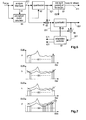
- the lossy encoder 41 includes an analysis filter-bank 61 and a perceptual model calculator 64 which both receive the original input signal S PCM .
- the output signal of filter bank 61 passes to the first input of a subtractor 65 and through a first quantisation means 62 to the second input of a first subtractor 65 and to an encoding and bit stream packing means 63 that provides the lossy bitstream 411.
- the analysis filter-bank 61 converts signal S PCM into the sub-band domain.
- An example spectrum of signal 611 is depicted in Fig. 7a, showing the amplitudes A of the spectrum versus the frequency f .
- Signal 611 is quantised in the first quantiser 62 according to the control of the perceptual model provided by calculator 64.
- An error signal 651 is calculated by subtracting the quantised sub-band samples 621 from the original sub-band samples 611. Usually the amplitude of this error signal is proportional to the masking thresholds determined in the perceptual model.
- An example error signal 651 is depicted in Fig. 7b in comparison to signal 611.
- the error signal 651 is quantised in a second quantisation means 66 in such a way that a further error signal 681 is calculated within an adaptation control loop formed by a second subtractor 68 and an adaptation controller 67, which further error signal 681 is the difference between signal 651 and the output signal of the second quantiser 66 and approaches a white spectrum, as depicted in Fig. 7c together with signals 611 and 651.
- the output signal of second quantiser 66 represents spectral whitening data 661 that is sent as part of the side information 412 to lossy decoder 42 and to lossless encoder and packer 45.
- Adaptation control 67 controls second quantiser 66 and takes care to find the right quantisation and the right bit rate for signal 661. If the bit rate exceeds a pre-determined threshold value and the error spectrum 681 is therefore not estimated 'white', within side information 412 an escape signal 671 is sent indicating that the lossless encoder and packer 45 shall use additional LPC de-correlation.
- Adaptation control 67 sets the optimum quantisation step for quantiser 66 to enable a flat noise floor, see signal 681 in Fig. 7c. This control may include a power analysis of signal 651.
- the second task of adaptation control 67 is to observe an estimation of the bit rate of the entropy encoded signal 661.
- Signal 661 is later entropy coded in step or stage 93.
- the bit rate of the entropy coded signal 661 is a main contribution to the overall rate of the ⁇ lossless' bit-stream 451. In case this bit rate estimate exceeds a threshold the escape signal 671 to use additional LPC de-correlation in time domain is sent.
- adaptation control 67 can optimise signal 661 such that signal 681 is no longer white (i.e. it uses different quantisation steps over the frequency bin axis).
- the noise floor 681 is then formed to match the characteristics of a given LPC de-correlator filter out of a dictionary of different LPC filters.
- the adaptation control process then becomes iterative in order to find the closest match of signal 681 with lowest costs (i.e. share of bit rate). This embodiment is depicted in Fig. 7d.
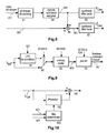
- the lossy decoder 42 shown in Fig. 8 receives lossy bit stream 411 which is de-packed in a bit stream depacker 81 and is decoded (including inverse quantiser scale factor processing if applicable) in a sub-band sample decoder 82 to create a sub-band sample signal 821 which is identical to signal 621 in the lossy encoder in Fig. 6.
- Signal 821 is transformed back to the time domain in a synthesis filter bank 83 that restores in each case a block of data values of signal S Dec .
- the spectral whitening data 661 (which is received from the lossless extension stream following de-packing) is added in a combiner 84 to signal 821, in order to form a signal 841 that has a quantisation error in the sub-band domain which is identical to the quantisation error of signal 681 in figures 6 and 7c.
- a synthesis filter bank 85 transforms signal 841 back to the time domain and restores in each case a block of data values of signal S' Dec . Because normally either signal S Dec or signal S' Dec is output, a single synthesis filter can be used that is connected to either signal 821 or signal 841, respectively.
- the lossy decoder should be realised in a platform independent manner using special integer arithmetic operations. Decoding a given bit stream to signal S' Dec within the lossless decoder at encoding or at decoding side needs to produce numerically equivalent results on every platform like ARM based, Intel Pentium based, or DSP based platforms.
- Lossy encoding and decoding induces a delay between the signals S PCM and S' Dec in Fig. 4.
- the lossy encoder is aware of this delay and will control First-In First-Out buffering in buffer 43 to guarantee sample-exact (i.e. synchronised) operation at subtractor 44 in Fig. 4.
- the buffer 43 can be replaced by using synchronisation means as described in US-B-6903664 .
- the lossy encoder will insert information items indicating the coding delay and the original file length into the auxiliary data part of the lossy bit stream of the first one or two audio frames as well as into the first frame of the lossless extension.
- the lossy decoder 42 and 51 will read this information and skip the first decoded (zero) samples indicated by the delay information.
- the lossless encoder and packer 45 of Fig. 4 is shown in more detail in Fig. 9.
- the error signal S Diff is highly de-correlated and can be entropy coded in entropy encoder 93, for which coding the preferred embodiment uses a Golomb-Rice coding.
- Spectral whitening data 661 (from bus 412) is also entropy coded in encoder 93 using a different entropy coding method, e.g. Huffman coding.
- the packer 94 forms a frame based bit stream using the entropy coded data 931 and additional information items 412 like escape signal 671 from lossy encoder 41, and outputs the lossless extension stream 451.
- the error signal S Diff can be further de-correlated using a linear prediction in an LPC de-correlator 91, which is shown in more detail in Fig. 10.
- LPC de-correlator 91 receives helper information from bus 421. The switching according to escape signal 671 (from bus 412) is performed by switch 92.
- a version passed through predictor 102 is subtracted in a subtractor 101. Its output signal is fed to switch 92.
- Predictor 102 uses a filter that is calculated using a filter determinator 103, the filter coefficients of which are derived from the helper information signal from bus 421.
- Filter determinator 103 can operate as follows:
- a set of LPC filter-coefficients is selected from a directory of LPS filter coefficient sets by adaptation controller 67. Then signal 631 becomes the directory index for the selected set of coefficients and is passed to packer 94 for transmission.
- the side information buses 412 and 421 carry data from lossy encoder 41 to lossy decoder 42 and from either one to the lossless encoder and packer 45, and these buses include the following data elements:
- the decoding is carried out using a lossy decoder 25 and a lossless decoder 27, the output signals of which are combined to regain the original input signal samples S PCM .
- the decoding can be carried out in different modes.
- the decoder can decode any compliant lossy bit stream 411 without a lossless extension stream 451 being present, and provides signal S Dec . This mode is also active when a lossless extension stream 451 is present but no permission is provided to use another mode. Preferably, the decoder will check the lossless extension stream for a matching permission ID in its rights data-base.
- This intermediate-quality mode is also enabled by a permission check in the decoder when examining the lossless extension stream data. Only the whitening data 661 is de-packed and used by the lossy decoder to provide signal S' Dec .
- the lossless mode decoding is started following a positive permission check result, and signal S PCM is output.
- the corresponding lossy decoder 51 is depicted in Fig. 8 in more detail.
- the modes of operation are signalled within side information 521 from the lossless de-packer and decoder 52. Basically, the same details apply as described for the lossy decoder 42.
- the encoded lossy bit stream 411 enters a means 81 for de-packing the bit stream, followed by means 82 for decoding the subband samples and by a synthesis filter bank 83 that outputs the decoded lossy PCM signal S Dec .
- the output signal 821 from means 82 is combined in an adder 84 with the corresponding spectral whitening data 661.
- the combined signal 841 enters a second synthesis filter bank 85 that outputs the decoded lossy PCM signal S' Dec .
- Fig. 11 shows the lossless de-packer and decoder 52 in more detail.
- the lossless de-packer 111 receives the lossless extension stream 451 which is parsed and de-packed. Control information is routed to operation controller 115 in which in case of file-to-file applications a consistency check can be performed to identify integrity with respect to the lossy bit stream 411.
- a reference fingerprint e.g. CRC data
- a current fingerprint is calculated over a certain data block of the lossy bit stream 411. If both finger prints are identical the normal operation proceeds.
- a permission check may be performed as a next step to identify the allowed mode or modes of operation.
- Corresponding information items 1151 received from an external database are used for comparison with permission identifiers of the received bit stream.
- the current mode is determined and a corresponding signal 1152 is used to send related information to the lossy decoder 51 using the side information channel 521.
- means for deciphering an encrypted lossless extension stream might also be used.
- the audio extension signal data 1111 is entropy decoded in an entropy decoder 112.
- the entropy encoded spectral whitening data items are correspondingly entropy decoded, e.g. in encoder 112.
- the decoded whitening data 661 is sent to the lossy decoder 51 and the difference signal data S Diff is sent to the combiner or summation unit 53. If escape information to apply additional LPC synthesis is identified in the bit stream 451 by de-packer 111 and operation controller 115, that controller will use signal 1153 to switch switcher 113 to the LPC synthesis path.
- the coefficients of LPC synthesis filter 114 are calculated using helper information 1141 which is provided from de-packer 111, or which can be determined from the lossy bit stream scale-factors or from the decoder sub-band signal 841 and additional information transmitted in the lossless extension bit stream 451 like missing scale-factors or spectral power information of high frequency bands not transmitted in lossy bit stream 411, or an index value pointing to a set of predefined LPC coefficients.
- the side information 521 exchanged between lossy decoder 51 and lossless de-packer and decoder 52 includes the following information and data elements:
- Frame data elements of the lossless extension bit stream bit stream are:
- a lossless extension stream file format is shown in Fig. 12.
- a file header provides side information to start the process of decoding. Following the header data, data frames of variable length containing data for reconstructing an intermediate-quality audio signal and for reconstructing a lossless-quality audio signal are arranged.
- File header data :
- the lossy bit stream 411 and the lossless extension stream 451 can be formatted for different storage or streaming applications, see Fig. 13.
- the output signals 411 and 451 of the lossy based lossless encoding 131 are fed to a bit stream formatter 132.
- the resulting output signal 1322 can be a single stream or file or can consist of two streams or two files.
- a rights management processing may be applied by supplying formatter 132 with corresponding rights management data 1321.
- a corresponding bit stream de-formatter can be used.
Abstract
In lossy based lossless coding a PCM audio signal passes through a lossy encoder (41) to a lossy decoder (42). The lossy encoder provides a lossy bit stream. The difference signal (SDiff) between the PCM signal and the lossy decoder output is lossless encoded (52), providing an extension bit stream. The invention facilitates enhancing a lossy perceptual audio encoding/decoding by an extension that enables mathematically exact reproduction of the original waveform using enhanced de-correlation, and provides additional data for reconstructing at decoder site an intermediate-quality audio signal. The lossless extension can be used to extend the widely used mp3 encoding/decoding to lossless encoding/decoding and superior quality mp3 encoding/de-coding.
Description
- The invention relates to a method and to an apparatus for lossless encoding of a source signal, using a lossy encoded data stream and a lossless extension data stream which together form a lossless encoded data stream for said source signal. Lossy perceptual audio coding data are enhanced by extension data that enable mathematically exact (lossless) reproduction of the original audio signal waveform.
- The basic principle of lossless audio coding is depicted in Fig. 1. The digital PCM Audio signal samples are not independent to each other. A
signal de-correlation 11 is used to reduce this dependency beforeentropy coding 12. This process needs to be reversible, to be able to restore the original signal. Known de-correlation techniques are using Linear Predictive Filtering (also known as Linear Predictive Coding LPC), integer filter-banks and lossy based approaches. - The basic principle of lossy based lossless coding is depicted in Fig. 2 and Fig. 3. In the encoding part (left side) in Fig. 2, a PCM audio input signal SPCM passes through a
lossy encoder 21 to alossy decoder 22 and as a lossy bit stream to alossy decoder 25 in the decoding part (right side). Lossy encoding and decoding is used to de-correlate the signal. The output signal ofdecoder 22 is removed from the input signal SPCM in asubtractor 23, and the resulting difference signal passes through alossless encoder 24 as an extension bit stream to alossless decoder 27. The output signals of thedecoders - This basic principle is disclosed for audio coding in
EP-B-0756386 andUS-B-6498811 , and is also discussed in P. Craven, M. Gerzon, "Lossless Coding for Audio Discs", J. Audio Eng. Soc., Vol.44, No.9, September 1996, and in J. Koller, Th. Sporer, K.H. Brandenburg, "Robust Coding of High Quality Audio Signals", AES 103rd Convention, Preprint 4621, August 1997. - In the lossy encoder in Fig. 3, the PCM audio input signal SPCM passes through an
analysis filter bank 31 and aquantisation 32 of sub-band samples to a coding andbit stream packing 33. The quantisation is controlled by aperceptual model calculator 34 that receives signal SPCM and corresponding information from theanalysis filter bank 31.
At decoder side, the encoded lossy bit stream enters ameans 35 for de-packing the bit stream, followed bymeans 36 for decoding the subband samples and by asynthesis filter bank 37 that outputs the decoded lossy PCM signal SDec.
Examples for lossy encoding and decoding are described in detail in the standard ISO/IEC 11172-3 (MPEG-1 Audio). - Because a lossy encoder produces an error signal SDiff that is proportional to the masking thresholds in the frequency domain, the signal is not very well de-correlated and therefore sub-optimum for entropy coding. As a consequence, the following publications focus on a special handling of the error signal SDiff. The common approach is to apply variations of LPC de-correlation schemes to the error signal SDiff:
WO-A-9953677 US-A-20040044520 ,WO-A-2005098823 . InEP-A-0905918 the amplitude of the error signal SDiff is used with a feedback loop to the quantisation stage of the lossy encoder part in order to control the quantisation in the lossy encoder and thus to generate a better de-correlation of the error signal SDiff. - When providing a lossless coding extension for lossy coding it is desirable to facilitate this in a scalable manner.
- A problem to be solved by the invention is to provide an improved lossless coding/decoding extension for lossy coding/decoding in a scalable manner, the lossy coding/decoding being based for example on mp3 (MPEG-1 Audio Layer 3). This problem is solved by the encoding method disclosed in
claim 1 and the decoding methods inclaims claims - The invention facilitates enhancing a lossy perceptual audio encoding/decoding by an extension that enables mathematically exact reproduction (i.e. lossless encoding/deco-ding) of the original waveform. The lossy based lossless coding makes use of enhanced de-correlation by means of spectral de-correlation build into the lossy encoder-decoder and additional temporal LPC de-correlation, where the LPC filter parameters need not be transmitted.
Advantageously, the inventive lossless extension can be used to extend the widely used mp3 encoding/decoding to lossless encoding/decoding. - In principle, the inventive encoding method is suited for lossless encoding of a source signal, using a lossy encoded data stream and a lossless extension data stream which together form a lossless encoded data stream for said source signal, said method including the steps:
- lossy encoding said source signal, wherein said lossy encoding provides said lossy encoded data stream as well as spectral whitening data;
- correspondingly lossy decoding said lossy encoded data, thereby reconstructing a standard decoded signal and, using said spectral whitening data, constructing from said standard decoded signal a superior quality decoded signal;
- forming a difference signal between said source signal and said superior quality decoded signal and lossless encoding said difference signal;
- packing said encoded difference signal together with said spectral whitening data to form said lossless extension data stream.
- In principle the inventive encoding apparatus is suited for lossless encoding of a source signal, using a lossy encoded data stream and a lossless extension data stream which together form a lossless encoded data stream for said source signal, said apparatus including:
- means being adapted for lossy encoding said source signal, wherein said lossy encoding provides said lossy encoded data stream as well as spectral whitening data;
- means being adapted for correspondingly lossy decoding said lossy encoded data, thereby reconstructing a standard decoded signal and, using said spectral whitening data, for constructing from said standard decoded signal a superior quality decoded signal;
- means being adapted for forming a difference signal between said source signal and said superior quality decoded signal and for lossless encoding said difference signal and for packing said encoded difference signal together with said spectral whitening data to form said lossless extension data stream.
- In principle, the inventive decoding method is suited for decoding a lossless encoded source signal data stream, which data stream was derived from a lossy encoded data stream and a lossless extension data stream which together form a lossless encoded data stream for said source signal,
wherein said source signal was lossy encoded, said lossy encoding providing said lossy encoded data stream as well as spectral whitening data,
and wherein said lossy encoded data were correspondingly lossy decoded, thereby reconstructing a standard decoded signal and, using said spectral whitening data, a superior quality decoded signal was constructed from said standard decoded signal,
and wherein a difference signal between said source signal and said superior quality decoded signal was formed and lossless encoded,
and wherein said lossless encoded difference signal was packed together with said spectral whitening data to form said lossless extension data stream,
said method including the steps: - de-packing said lossless extension data stream and decoding said lossless encoded difference signal so as to provide said difference signal and said spectral whitening data;
- lossy decoding said lossy encoded data stream, thereby reconstructing said standard decoded signal and, using said spectral whitening data, reconstructing said superior quality decoded signal from said standard decoded signal;
- forming from said decoded lossless encoded difference signal and from said superior quality decoded signal a reconstructed source signal.
- In principle the inventive decoding apparatus is suited for for decoding a lossless encoded source signal data stream, which data stream was derived from a lossy encoded data stream and a lossless extension data stream which together form a lossless encoded data stream for said source signal,
wherein said source signal was lossy encoded, said lossy encoding providing said lossy encoded data stream as well as spectral whitening data,
and wherein said lossy encoded data were correspondingly lossy decoded, thereby reconstructing a standard decoded signal and, using said spectral whitening data, a superior quality decoded signal was constructed from said standard decoded signal,
and wherein a difference signal between said source signal and said superior quality decoded signal was formed and lossless encoded,
and wherein said lossless encoded difference signal was packed together with said spectral whitening data to form said lossless extension data stream,
said apparatus including: - means being adapted for de-packing said lossless extension data stream and for decoding said lossless encoded difference signal so as to provide said difference signal and said spectral whitening data;
- means being adapted for lossy decoding said lossy encoded data stream, thereby reconstructing said standard decoded signal and, using said spectral whitening data, reconstructing said superior quality decoded signal from said standard decoded signal;
- means being adapted for forming from said decoded lossless encoded difference signal and from said superior quality decoded signal a reconstructed source signal.
- In principle, the further inventive decoding method is suited for decoding a lossless encoded source signal data stream, which data stream was derived from a lossy encoded data stream and a lossless extension data stream which together form a lossless encoded data stream for said source signal,
wherein said source signal was lossy encoded, said lossy encoding providing said lossy encoded data stream as well as spectral whitening data,
and wherein said lossy encoded data were correspondingly lossy decoded, thereby reconstructing a standard decoded signal and, using said spectral whitening data, a superior quality decoded signal was constructed from said standard decoded signal,
and wherein a difference signal between said source signal and said superior quality decoded signal was formed and lossless encoded,
and wherein said lossless encoded difference signal was packed together with said spectral whitening data to form said lossless extension data stream,
said method including the steps: - de-packing said lossless extension data stream so as to provide said spectral whitening data;
- lossy decoding said lossy encoded data stream, thereby reconstructing said standard decoded signal and, using said spectral whitening data, reconstructing said superior quality decoded signal from said standard decoded signal.
- In principle the further inventive decoding apparatus is suited for decoding a lossless encoded source signal data stream, which data stream was derived from a lossy encoded data stream and a lossless extension data stream which together form a lossless encoded data stream for said source signal,
wherein said source signal was lossy encoded, said lossy encoding providing said lossy encoded data stream as well as spectral whitening data,
and wherein said lossy encoded data were correspondingly lossy decoded, thereby reconstructing a standard decoded signal and, using said spectral whitening data, a superior quality decoded signal was constructed from said standard decoded signal,
and wherein a difference signal between said source signal and said superior quality decoded signal was formed and lossless encoded,
and wherein said lossless encoded difference signal was packed together with said spectral whitening data to form said lossless extension data stream,
said apparatus including: - means being adapted for de-packing said lossless extension data stream so as to provide said spectral whitening data;
- means being adapted for lossy decoding said lossy encoded data stream, thereby reconstructing said standard decoded signal and, using said spectral whitening data, reconstructing said superior quality decoded signal from said standard decoded signal.
- Advantageous additional embodiments of the invention are disclosed in the respective dependent claims.
- Exemplary embodiments of the invention are described with reference to the accompanying drawings, which show in:
- Fig. 1
- known principle of lossless audio signal compression;
- Fig. 2
- basic block diagram for a known lossy based lossless encoder and decoder;
- Fig. 3
- known principle operation of a lossy encoder and a lossy decoder;
- Fig. 4
- block diagram for the inventive lossy based lossless encoding;
- Fig. 5
- block diagram for the inventive lossy based lossless decoding;
- Fig. 6
- more detailed block diagram for the lossy encoder in Fig. 4;
- Fig. 7
- example signals:
- a) discrete signal spectrum in lossy encoder subband domain,
- b) error signal following perceptually controlled quantisation,
- c) error signal following whitening,
- d) spectral noise shaping to adapt to a given LPC filter signal;
- Fig. 8
- more detailed block diagram for the lossy decoder in Fig. 5;
- Fig. 9
- more detailed block diagram for the lossless encoder and packer in Fig. 4;
- Fig. 10
- LPC de-correlator;
- Fig. 11
- more detailed block diagram for the lossless de-packer and decoder in Fig. 5;
- Fig. 12
- extension file structure;
- Fig. 13
- bit stream formatting.
- The invention solves the problem of suboptimum de-correlation of lossy based lossless coding by making use of a modified lossy encoder like
encoder 41 shown in Fig. 4. Besides of producing from the original input signal SPCM a compliantlossy bit stream 411, this encoder generates special spectral whitening data which is sent, besides other information, asside information 412 to a corresponding modifiedlossy decoder 42 and to a lossless encoder andpacker 45 outputting a lossless extension bit stream. Thelossy encoder 41 is shown in more detail in Fig. 6. The spectral whitening data are formed as explained in connection with figures 6 and 7. In the modifiedlossy decoder 42 thelossy bit stream 411 is decoded and the frequency spectrum for the current frame of the input signal is restored whereby the spectral whitening data fromsignal 412 is added to the spectrum. Thereafter in decoder 42 a synthesis filter bank is applied, and a time domain error signal SDiff is calculated in asubtractor 44 by subtracting the correspondingdecoder 42 output signal S'Dec from the input signal SPCM that has been correspondingly delayed by abuffer 43 in order to compensate for the required processing time inencoder 41 anddecoder 42. The error signal SDiff now has a white (i.e. a flat) frequency power spectrum, which is equivalent to having a high de-correlation, and thus is suited for efficient entropy coding. Signal SDiff is fed to a lossless encoder andpacker 45 which contains an entropy encoder and includes in itslossless extension stream 451 output lossy encoderside information data 412 provided fromencoder 41 and lossy decoderside information data 421 provided bydecoder 42.
To increase the lossless coding efficiency, the modifiedlossy encoder 41 can reduce the amount of whitening data (and thus the related bit rate) in favour of an additional LPC filter placed inside the lossless encoder andpacker 45. The LPC filter coefficients are determined using lossy bit stream elements like scale factors or the block spectrum indecoder 42 in the preferred embodiment, and only a very small amount of additional data needs to be transmitted to enable calculation of the filter coefficients at decoder side. - In the lossy based lossless decoding in Fig. 5 the
lossy bit stream 411 is decoded in a modifiedlossy decoder 51 that outputs a (known) lossy encoded and decoded output signal SDec, e.g. a decoded mp3 signal, which may be denoted aslossy mode 1.
When receiving thelossless extension stream 451, consistency to match thelossy bit stream 411 and a permission check to allow decoding for different modes can be performed, e.g. in a lossless de-packer anddecoder 52. The different modes can be thelossy mode 1, alossy mode 2 and alossless mode 3.
If not operating inmode 1 only, received spectral whitening data is de-packed inmeans 52 and is sent (among other information) asside information 521 to thelossy decoder 51, in which spectral whitening data is added to the restored spectrum and a synthesis filter-bank is applied to create the output signal S'Dec. In lossy mode 2 S'Dec is the output signal. This is a lossy signal which is superior to signal SDec in terms of perceptual quality and is called 'intermediate quality' in the following description. It is not necessary to decode the lossless encoded difference signal SDiff.
Inlossless mode 3 thelossless extension stream 451 is further de-packed inmeans 52 and entropy decoding is applied therein, and an optional LPC synthesis can be applied if signalled correspondingly in the losslessextension bit stream 451. In a preferred embodiment the LPC synthesis filter coefficients are determined using corresponding information items fromlossy bit stream 411 data elements like scale factors or the spectrum of related lossy coefficient blocks in sub-band domain of thelossy decoder 51, as well as optional helper information items transmitted inside thelossless extension stream 451. The error signal SDiff is restored inmeans 52 and is synchronised to signal S'Dec. The error signal SDiff and the signal S'Dec (i.e. the intermediate quality signal) are combined in anadder 53 so as to regain the mathematically lossless reconstruction of the original signal SPCM. - The
lossy decoder 51 operates exactly likelossy decoder 42 in the encoding part in terms of calculation of signal S'Dec- Signal S'Dec in the decoding part and signal S'Dec in the encoding part are mathematically identical, as well as signals SDiff in the decoding part and SDiff in the encoding part.
Advantageously, thelossy decoder implementations means 52 and means 45 can be realised platform independent using integer arithmetic. - The
lossy encoder 41 of Fig. 4 is explained in more detail in connection with Fig. 6. Thelossy decoder 51 of Fig. 5 is explained in more detail in connection with Fig. 8. By combininglossy encoder 41 andlossy decoder 42 in Fig. 4, simplifications are feasible. - The
lossy encoder 41 includes an analysis filter-bank 61 and aperceptual model calculator 64 which both receive the original input signal SPCM. The output signal offilter bank 61 passes to the first input of asubtractor 65 and through a first quantisation means 62 to the second input of afirst subtractor 65 and to an encoding and bit stream packing means 63 that provides thelossy bitstream 411. The analysis filter-bank 61 converts signal SPCM into the sub-band domain.
An example spectrum ofsignal 611 is depicted in Fig. 7a, showing the amplitudes A of the spectrum versus the frequency f.
Signal 611 is quantised in thefirst quantiser 62 according to the control of the perceptual model provided bycalculator 64. Anerror signal 651 is calculated by subtracting the quantisedsub-band samples 621 from theoriginal sub-band samples 611. Usually the amplitude of this error signal is proportional to the masking thresholds determined in the perceptual model. Anexample error signal 651 is depicted in Fig. 7b in comparison to signal 611.
Theerror signal 651 is quantised in a second quantisation means 66 in such a way that afurther error signal 681 is calculated within an adaptation control loop formed by asecond subtractor 68 and anadaptation controller 67, whichfurther error signal 681 is the difference betweensignal 651 and the output signal of thesecond quantiser 66 and approaches a white spectrum, as depicted in Fig. 7c together withsignals second quantiser 66 representsspectral whitening data 661 that is sent as part of theside information 412 tolossy decoder 42 and to lossless encoder andpacker 45.Adaptation control 67 controls second quantiser 66 and takes care to find the right quantisation and the right bit rate forsignal 661. If the bit rate exceeds a pre-determined threshold value and theerror spectrum 681 is therefore not estimated 'white', withinside information 412 anescape signal 671 is sent indicating that the lossless encoder andpacker 45 shall use additional LPC de-correlation.Adaptation control 67 sets the optimum quantisation step forquantiser 66 to enable a flat noise floor, seesignal 681 in Fig. 7c. This control may include a power analysis ofsignal 651. An iterative process is not necessary.
The second task ofadaptation control 67 is to observe an estimation of the bit rate of the entropy encodedsignal 661.Signal 661 is later entropy coded in step orstage 93. The bit rate of the entropy codedsignal 661 is a main contribution to the overall rate of the `lossless' bit-stream 451. In case this bit rate estimate exceeds a threshold theescape signal 671 to use additional LPC de-correlation in time domain is sent. - In another embodiment,
adaptation control 67 can optimise signal 661 such that signal 681 is no longer white (i.e. it uses different quantisation steps over the frequency bin axis). Thenoise floor 681 is then formed to match the characteristics of a given LPC de-correlator filter out of a dictionary of different LPC filters. The adaptation control process then becomes iterative in order to find the closest match ofsignal 681 with lowest costs (i.e. share of bit rate). This embodiment is depicted in Fig. 7d. - The
lossy decoder 42 shown in Fig. 8 receiveslossy bit stream 411 which is de-packed in abit stream depacker 81 and is decoded (including inverse quantiser scale factor processing if applicable) in asub-band sample decoder 82 to create asub-band sample signal 821 which is identical to signal 621 in the lossy encoder in Fig. 6.Signal 821 is transformed back to the time domain in asynthesis filter bank 83 that restores in each case a block of data values of signal SDec. The spectral whitening data 661 (which is received from the lossless extension stream following de-packing) is added in acombiner 84 to signal 821, in order to form asignal 841 that has a quantisation error in the sub-band domain which is identical to the quantisation error ofsignal 681 in figures 6 and 7c. Asynthesis filter bank 85 transforms signal 841 back to the time domain and restores in each case a block of data values of signal S'Dec. Because normally either signal SDec or signal S'Dec is output, a single synthesis filter can be used that is connected to either signal 821 or signal 841, respectively. - The lossy decoder should be realised in a platform independent manner using special integer arithmetic operations. Decoding a given bit stream to signal S'Dec within the lossless decoder at encoding or at decoding side needs to produce numerically equivalent results on every platform like ARM based, Intel Pentium based, or DSP based platforms.
- Lossy encoding and decoding induces a delay between the signals SPCM and S'Dec in Fig. 4. When operating the lossless encoder in streaming real-time applications the lossy encoder is aware of this delay and will control First-In First-Out buffering in
buffer 43 to guarantee sample-exact (i.e. synchronised) operation atsubtractor 44 in Fig. 4. When operating the lossless encoder for file-to-file operations, e.g. converting PCM Audio files to lossless encoded files, thebuffer 43 can be replaced by using synchronisation means as described inUS-B-6903664 .
In the preferred embodiment the lossy encoder will insert information items indicating the coding delay and the original file length into the auxiliary data part of the lossy bit stream of the first one or two audio frames as well as into the first frame of the lossless extension. Thelossy decoder - The lossless encoder and
packer 45 of Fig. 4 is shown in more detail in Fig. 9. During regular operation the error signal SDiff is highly de-correlated and can be entropy coded inentropy encoder 93, for which coding the preferred embodiment uses a Golomb-Rice coding. Spectral whitening data 661 (from bus 412) is also entropy coded inencoder 93 using a different entropy coding method, e.g. Huffman coding. Thepacker 94 forms a frame based bit stream using the entropy codeddata 931 andadditional information items 412 like escape signal 671 fromlossy encoder 41, and outputs thelossless extension stream 451. If indicated bylossy encoder 41 with theescape signal 671, the error signal SDiff can be further de-correlated using a linear prediction in anLPC de-correlator 91, which is shown in more detail in Fig. 10.LPC de-correlator 91 receives helper information frombus 421. The switching according to escape signal 671 (from bus 412) is performed byswitch 92. - In the LPC de-correlator in Fig. 10, from the input signal SDiff a version passed through
predictor 102 is subtracted in asubtractor 101. Its output signal is fed to switch 92.Predictor 102 uses a filter that is calculated using afilter determinator 103, the filter coefficients of which are derived from the helper information signal frombus 421.Filter determinator 103 can operate as follows: - The scale factors of the decoder are transmitted as
signal 421 to filterdeterminator 103. These scale factors si are used to estimate the spectral power of the residual in the transform domain:
- These spectral power values are duplicated to form an even sequence S'ee (i) with i =0, ..., Nband - 1, ..., 2Nband - 1. This is done to enable a real-valued inverse FFT sequence. Thereafter the auto-correlation is calculated by iFFT(S'ee (i)). The Levison-Durbin algorithm can be used to determine the LPC coefficients.
This procedure can also be used in the lossless decoder. If relevant parts of the higher frequency spectrum are not transmitted inside the lossyencoder bit stream 411, this missinginformation 631 is sent from step/stage 63 in the lossy encoder topacker 94 for transmission, and fromde-packer 111 to filterdeterminator 103. - A set of LPC filter-coefficients is selected from a directory of LPS filter coefficient sets by
adaptation controller 67. Then signal 631 becomes the directory index for the selected set of coefficients and is passed topacker 94 for transmission. - The
side information buses lossy encoder 41 tolossy decoder 42 and from either one to the lossless encoder andpacker 45, and these buses include the following data elements: - encoded spectral whitening data 661 (sent via
bus 412 fromencoder 41 todecoder 42 and to encoder/packer 45); - an
escape signal 671 to indicate additional LPC de-correlation (sent viabus 412 fromencoder 41 to encoder/packer 45, i.e. indicating that LPC de-correlation and LPC synthesis is active; - a helper information signal (sent via
bus 421 fromdecoder 42 to encoder/packer - a
helper information 631 sent fromlossy encoder 41 toencoder packer 45/94, for transmitting missing scale factors for high frequency bands or an index to a set of predefined LPC filter coefficients; - for file-to-file applications, lossy coder delay value and/or original file length value (sent via
bus 412 fromencoder 41 todecoder 42 and to encoder/packer 45). - As already described in connection with Fig. 2, the decoding is carried out using a
lossy decoder 25 and alossless decoder 27, the output signals of which are combined to regain the original input signal samples SPCM. Advantageously, the decoding can be carried out in different modes. - The decoder can decode any compliant
lossy bit stream 411 without alossless extension stream 451 being present, and provides signal SDec. This mode is also active when alossless extension stream 451 is present but no permission is provided to use another mode. Preferably, the decoder will check the lossless extension stream for a matching permission ID in its rights data-base. - This intermediate-quality mode is also enabled by a permission check in the decoder when examining the lossless extension stream data. Only the
whitening data 661 is de-packed and used by the lossy decoder to provide signal S'Dec. - The lossless mode decoding is started following a positive permission check result, and signal SPCM is output.
- The corresponding
lossy decoder 51 is depicted in Fig. 8 in more detail. The modes of operation are signalled withinside information 521 from the lossless de-packer anddecoder 52. Basically, the same details apply as described for thelossy decoder 42. The encodedlossy bit stream 411 enters ameans 81 for de-packing the bit stream, followed bymeans 82 for decoding the subband samples and by asynthesis filter bank 83 that outputs the decoded lossy PCM signal SDec. Theoutput signal 821 from means 82 is combined in anadder 84 with the correspondingspectral whitening data 661. The combinedsignal 841 enters a secondsynthesis filter bank 85 that outputs the decoded lossy PCM signal S'Dec. - Fig. 11 shows the lossless de-packer and
decoder 52 in more detail. Thelossless de-packer 111 receives thelossless extension stream 451 which is parsed and de-packed.
Control information is routed tooperation controller 115 in which in case of file-to-file applications a consistency check can be performed to identify integrity with respect to thelossy bit stream 411. As an option, a reference fingerprint (e.g. CRC data) is extracted from thelossless extension stream 451 and a current fingerprint is calculated over a certain data block of thelossy bit stream 411. If both finger prints are identical the normal operation proceeds. A permission check may be performed as a next step to identify the allowed mode or modes of operation.Corresponding information items 1151 received from an external database are used for comparison with permission identifiers of the received bit stream. The current mode is determined and acorresponding signal 1152 is used to send related information to thelossy decoder 51 using theside information channel 521. In special embodiments, means for deciphering an encrypted lossless extension stream might also be used. Following de-packing, the audioextension signal data 1111 is entropy decoded in anentropy decoder 112. The entropy encoded spectral whitening data items are correspondingly entropy decoded, e.g. inencoder 112. The decodedwhitening data 661 is sent to thelossy decoder 51 and the difference signal data SDiff is sent to the combiner orsummation unit 53. If escape information to apply additional LPC synthesis is identified in thebit stream 451 byde-packer 111 andoperation controller 115, that controller will usesignal 1153 to switchswitcher 113 to the LPC synthesis path. The coefficients ofLPC synthesis filter 114 are calculated usinghelper information 1141 which is provided fromde-packer 111, or which can be determined from the lossy bit stream scale-factors or from the decoder sub-band signal 841 and additional information transmitted in the losslessextension bit stream 451 like missing scale-factors or spectral power information of high frequency bands not transmitted inlossy bit stream 411, or an index value pointing to a set of predefined LPC coefficients. - The
side information 521 exchanged betweenlossy decoder 51 and lossless de-packer anddecoder 52 includes the following information and data elements: - a mode indicator signal 1152 (sent to decoder 52);
- spectral whitening data 661 (sent to decoder 52);
-
helper information 1141 fromlossy decoder 42 to determine LPC filter coefficients (sent to lossless de-packer and decoder 52); - lossy coder delay value and/or original file length value for file-to-file applications (sent to decoder 52).
- The following data elements can be provided within the lossless extension bit stream as header data elements:
- a fingerprint to unambiguously identify corresponding lossy bit stream. This element is needed especially for two files applications and might be disregarded for container (one file) and streaming applications;
- mode indicators and corresponding DRM information;
- synchronisation information (lossy coding delay, original file length, file end indicator);
- PCM word size of original signal (16, 20 or 24 bits);
- cue point information enabling a faster addressing of lossless data frames inside the (variable bit rate) stream, consisting of a table of constant frame interval pointers and an frame interval length indicator.
- In file-to-file applications these information items need to be provided only once at the beginning of the lossless bit stream. In streaming applications these information items, excluding the cue- point data, need to be sent every N frames.
- Frame data elements of the lossless extension bit stream bit stream are:
- a frame boundary indicator to enable frame-synchronous operation for the lossy bit stream;
- coded spectral error (i.e. whitening) data;
- escape information indicating the use of additional LPC synthesis, and LPC helper information;
- the encoded time error signal data.
- A lossless extension stream file format is shown in Fig. 12. A file header provides side information to start the process of decoding. Following the header data, data frames of variable length containing data for reconstructing an intermediate-quality audio signal and for reconstructing a lossless-quality audio signal are arranged.
File header data: - header ID;
- header length;
- fingerprint (e.g. CRC32 data);
- mode indication information block;
- side info: codec delay, original file length, PCM word size, sample rate;
- a cue point table data block: block-length value, interval info in frames, number of table entries, pointer-table.
- sync word (optional) and frame length;
- coded spectral error (i.e. whitening) data: block-length, coded data. This is the data required to decode to intermediate quality (mode 2). Decoders operating in
mode 2 will skip the rest of the frame data if such data are present; - LPC helper information: block length value, LPC mode indicator, coded data;
- coded time error signal: block length value, coded data.
- The
lossy bit stream 411 and thelossless extension stream 451 can be formatted for different storage or streaming applications, see Fig. 13. The output signals 411 and 451 of the lossy basedlossless encoding 131 are fed to abit stream formatter 132. The resultingoutput signal 1322 can be a single stream or file or can consist of two streams or two files. A rights management processing may be applied by supplyingformatter 132 with correspondingrights management data 1321.
At decoding side, a corresponding bit stream de-formatter can be used.
Claims (15)
- Method for lossless encoding of a source signal (SPCM), using a lossy encoded data stream (411) and a lossless extension data stream (451) which together form a lossless encoded data stream (1322) for said source signal, characterised by the steps:- lossy encoding (41) said source signal, wherein said lossy encoding provides said lossy encoded data stream (411) as well as spectral whitening data (661);- correspondingly lossy decoding (42) said lossy encoded data, thereby reconstructing a standard decoded signal (SDec) and, using said spectral whitening data, constructing from said standard decoded signal a superior quality decoded signal (S'Dec);- forming (43, 44) a difference signal (SDiff) between said source signal (SPCM) and said superior quality decoded signal (S'Dec) and lossless encoding (45) said difference signal;- packing said encoded difference signal together with said spectral whitening data (661) to form said lossless extension data stream (451).
- Apparatus for lossless encoding of a source signal (SPCM), using a lossy encoded data stream (411) and a lossless extension data stream (451) which together form a lossless encoded data stream (1322) for said source signal, said apparatus including:- means (41) being adapted for lossy encoding said source signal, wherein said lossy encoding provides said lossy encoded data stream (411) as well as spectral whitening data (661);- means (42) being adapted for correspondingly lossy decoding said lossy encoded data, thereby reconstructing a standard decoded signal (SDec) and, using said spectral whitening data, for constructing from said standard decoded signal a superior quality decoded signal (S'Dec);- means (43, 44, 45) being adapted for forming a difference signal (SDiff) between said source signal (SPCM) and said superior quality decoded signal (S'Dec) and for lossless encoding said difference signal and for packing said encoded difference signal together with said spectral whitening data (661) to form said lossless extension data stream (451).
- Method for decoding a lossless encoded source signal (SPCM) data stream, which data stream was derived from a lossy encoded data stream (411) and a lossless extension data stream (451) which together form a lossless encoded data stream (1322) for said source signal,
wherein said source signal was lossy encoded (41), said lossy encoding providing said lossy encoded data stream (411) as well as spectral whitening data (661),
and wherein said lossy encoded data were correspondingly lossy decoded (42), thereby reconstructing a standard decoded signal (SDec) and, using said spectral whitening data, a superior quality decoded signal (S'Dec) was constructed from said standard decoded signal,
and wherein a difference signal (SDiff) between said source signal (SPCM) and said superior quality decoded signal (S'Dec) was formed (43, 44) and lossless encoded (45),
and wherein said lossless encoded difference signal was packed together with said spectral whitening data (661) to form said lossless extension data stream (451),
said method including the steps:- de-packing (52) said lossless extension data stream (451) and decoding (52) said lossless encoded difference signal so as to provide said difference signal (SDiff) and said spectral whitening data (661);- lossy decoding (51) said lossy encoded data stream (411), thereby reconstructing said standard decoded signal (SDec) and, using said spectral whitening data, reconstructing (51) said superior quality decoded signal (S'Dec) from said standard decoded signal;- forming (53) from said decoded lossless encoded difference signal (SDiff) and from said superior quality decoded signal (S'Dec) a reconstructed source signal (SPCM) . - Apparatus for decoding a lossless encoded source signal (SPCM) data stream, which data stream was derived from a lossy encoded data stream (411) and a lossless extension data stream (451) which together form a lossless encoded data stream (1322) for said source signal,
wherein said source signal was lossy encoded (41), said lossy encoding providing said lossy encoded data stream (411) as well as spectral whitening data (661),
and wherein said lossy encoded data were correspondingly lossy decoded (42), thereby reconstructing a standard decoded signal (SDec) and, using said spectral whitening data, a superior quality decoded signal (S'Dec) was constructed from said standard decoded signal,
and wherein a difference signal (SDiff) between said source signal (SPCM) and said superior quality decoded signal (S'Dec) was formed (43, 44) and lossless encoded (45),
and wherein said lossless encoded difference signal was packed together with said spectral whitening data (661) to form said lossless extension data stream (451),
said apparatus including:- means (52) being adapted for de-packing said lossless extension data stream (451) and for decoding said lossless encoded difference signal so as to provide said difference signal (SDiff) and said spectral whitening data (661);- means (51) being adapted for lossy decoding said lossy encoded data stream (411), thereby reconstructing said standard decoded signal (SDec) and, using said spectral whitening data, reconstructing (51) said superior quality decoded signal (S'Dec) from said standard decoded signal;- means (53) being adapted for forming from said decoded lossless encoded difference signal (SDiff) and from said superior quality decoded signal (S'Dec) a reconstructed source signal (SPCM) . - Method for decoding a lossless encoded source signal (SPCM) data stream, which data stream was derived from a lossy encoded data stream (411) and a lossless extension data stream (451) which together form a lossless encoded data stream (1322) for said source signal,
wherein said source signal was lossy encoded (41), said lossy encoding providing said lossy encoded data stream (411) as well as spectral whitening data (661),
and wherein said lossy encoded data were correspondingly lossy decoded (42), thereby reconstructing a standard decoded signal (SDec) and, using said spectral whitening data, a superior quality decoded signal (S'Dec) was constructed from said standard decoded signal,
and wherein a difference signal (SDiff) between said source signal (SPCM) and said superior quality decoded signal (S'Dec) was formed (43, 44) and lossless encoded (45),
and wherein said lossless encoded difference signal was packed together with said spectral whitening data (661) to form said lossless extension data stream (451),
said method including the steps:- de-packing (52) said lossless extension data stream (451) so as to provide said spectral whitening data (661);- lossy decoding (51) said lossy encoded data stream (411), thereby reconstructing said standard decoded signal (SDec) and, using said spectral whitening data, reconstructing (51) said superior quality decoded signal (S'Dec) from said standard decoded signal. - Apparatus for decoding a lossless encoded source signal (SPCM) data stream, which data stream was derived from a lossy encoded data stream (411) and a lossless extension data stream (451) which together form a lossless encoded data stream (1322) for said source signal,
wherein said source signal was lossy encoded (41), said lossy encoding providing said lossy encoded data stream (411) as well as spectral whitening data (661),
and wherein said lossy encoded data were correspondingly lossy decoded (42), thereby reconstructing a standard decoded signal (SDec) and, using said spectral whitening data, a superior quality decoded signal (S'Dec) was constructed from said standard decoded signal,
and wherein a difference signal (SDiff) between said source signal (SPCM) and said superior quality decoded signal (S'Dec) was formed (43, 44) and lossless encoded (45),
and wherein said lossless encoded difference signal was packed together with said spectral whitening data (661) to form said lossless extension data stream (451),
said apparatus including:- means (52) being adapted for de-packing said lossless extension data stream (451) so as to provide said spectral whitening data (661);- means (51) being adapted for lossy decoding said lossy encoded data stream (411), thereby reconstructing said standard decoded signal (SDec) and, using said spectral whitening data, reconstructing (51) said superior quality decoded signal (S'Dec) from said standard decoded signal. - Method according to one of claims 1, 3 and 5, or apparatus according to one of claims 2, 4 and 6, wherein said spectral whitening data (661) are or were, respectively, generated by:- processing said source signal (SPCM) in an analysis filter bank (61) and quantising (62) its output signal and forming (65) the difference signal (651) between the analysis filter bank output signal (611) and the quantisation output signal (621), wherein said quantising is, or was, controlled by a perceptual model calculator (64);- quantising (66) said difference signal (651) thereby controlling (67) this further quantisation such that the difference signal (681) between the input and the output of said further quantisation approaches a white spectrum, whereby the output signal of said further quantisation forms said spectral whitening data (661).
- Method or apparatus according to claim 7, wherein:- said further quantisation (66) is controlled by an adaptation controller (67) that checks the current bit rate of said spectral whitening data (661) and, if said current bit rate exceeds a pre-determined threshold value, sets an escape signal (671);- said lossless encoding of said difference signal (SDiff) uses an entropy encoder (93) the input signal of which passes through an LPC de-correlator if said escape signal is set, and, respectively,
said lossless decoding of said lossless encoded difference signal (SDiff) uses an entropy decoder (112) the output signal of which passes through an LPC synthesis 114) if said escape signal was set at encoding site. - Method according to one of claims 1, 3, 5, 7 and 8, or apparatus according to one of claims 2, 4 and 6 to 8, wherein said spectral whitening data (661) are or were, respectively, entropy encoded (93) at encoding site and, respectively, are entropy decoded (112) at decoding site.
- Method or apparatus according to claim 8 or 9, wherein said LPC de-correlator and said LPC synthesis are an LPC filter, the filter coefficients of which are determined using information items like scale factors and/or the spectrum of related coefficient blocks in the sub-band domain of said lossy bit stream (411) and/or helper information items.
- Method according to one of claims 1, 3, 5 and 7 to 10, or apparatus according to one of claims 2, 4 and 6 to 10, wherein said lossless extension data stream (451) includes- encoded spectral whitening data (661);- an escape signal (671) indicating that LPC de-correlation is active;- a helper information signal;- for file-to-file applications, a lossy coder delay value and/or an original file length value.
- Lossless extension bit stream (451) including:- entropy encoded difference signal (SDiff) data;- encoded spectral whitening data (661);- an escape signal (671) indicating that LPC de-correlation is active;- a helper information signal;- for file-to-file applications, a lossy coder delay value and/or an original file length value, which data items and signals facilitate carrying out the method according to claims 3 or 5.
- Lossless encoded bit stream (1322), including lossy encoded signal data (411), e.g. mp3 data, and the data items and signals and optionally values defined in claim 12.
- Storage medium, for example on optical disc, that contains or stores, or has recorded on it, a digital video signal encoded according to the method of one of claims 1 and 7 to 11.
- Storage medium, for example on optical disc, that contains or stores, or has recorded on it, a bit stream according to claim 12 or 13.
Priority Applications (10)
| Application Number | Priority Date | Filing Date | Title |
|---|---|---|---|
| EP06113576A EP1852848A1 (en) | 2006-05-05 | 2006-05-05 | Method and apparatus for lossless encoding of a source signal using a lossy encoded data stream and a lossless extension data stream |
| KR1020087027032A KR101404335B1 (en) | 2006-05-05 | 2007-04-18 | Method and apparatus for generating a lossless encoded data stream for an audio source signal from a lossy encoded data stream and a lossless extension data stream |
| JP2009508301A JP5135330B2 (en) | 2006-05-05 | 2007-04-18 | Method and apparatus for lossless encoding of a source signal using a lossy encoded data stream and a lossless extended data stream |
| CN2007800156126A CN101432610B (en) | 2006-05-05 | 2007-04-18 | Method and apparatus for lossless encoding of a source signal using a lossy encoded data stream and a lossless extension data stream |
| US12/226,992 US8428941B2 (en) | 2006-05-05 | 2007-04-18 | Method and apparatus for lossless encoding of a source signal using a lossy encoded data stream and a lossless extension data stream |
| DE602007005119T DE602007005119D1 (en) | 2006-05-05 | 2007-04-18 | METHOD AND DEVICE FOR LOSSELY CODING A SOURCE SIGNAL USING A LOSS-CONFIDENTATED DATA STREAM AND A LOSS-FREE EXTENSION DATA CURRENT |
| PCT/EP2007/053783 WO2007128661A1 (en) | 2006-05-05 | 2007-04-18 | Method and apparatus for lossless encoding of a source signal using a lossy encoded data stream and a lossless extension data stream |
| EP07728245A EP2016383B1 (en) | 2006-05-05 | 2007-04-18 | Method and apparatus for lossless encoding of a source signal using a lossy encoded data stream and a lossless extension data stream |
| AT07728245T ATE459868T1 (en) | 2006-05-05 | 2007-04-18 | METHOD AND DEVICE FOR LOSSLESSLY CODING A SOURCE SIGNAL USING A LOSSY CODED DATA STREAM AND A LOSSLESS EXTENSION DATA STREAM |
| BRPI0711190-8A BRPI0711190B1 (en) | 2006-05-05 | 2007-04-18 | METHOD AND APPARATUS FOR LOSS-FREE CODING OF A SIGN OF ORIGIN USING A LOSS-ENCODED DATA FLOW AND A LOSS-FREE EXTENSION DATA FLOW |
Applications Claiming Priority (1)
| Application Number | Priority Date | Filing Date | Title |
|---|---|---|---|
| EP06113576A EP1852848A1 (en) | 2006-05-05 | 2006-05-05 | Method and apparatus for lossless encoding of a source signal using a lossy encoded data stream and a lossless extension data stream |
Publications (1)
| Publication Number | Publication Date |
|---|---|
| EP1852848A1 true EP1852848A1 (en) | 2007-11-07 |
Family
ID=36694486
Family Applications (2)
| Application Number | Title | Priority Date | Filing Date |
|---|---|---|---|
| EP06113576A Withdrawn EP1852848A1 (en) | 2006-05-05 | 2006-05-05 | Method and apparatus for lossless encoding of a source signal using a lossy encoded data stream and a lossless extension data stream |
| EP07728245A Not-in-force EP2016383B1 (en) | 2006-05-05 | 2007-04-18 | Method and apparatus for lossless encoding of a source signal using a lossy encoded data stream and a lossless extension data stream |
Family Applications After (1)
| Application Number | Title | Priority Date | Filing Date |
|---|---|---|---|
| EP07728245A Not-in-force EP2016383B1 (en) | 2006-05-05 | 2007-04-18 | Method and apparatus for lossless encoding of a source signal using a lossy encoded data stream and a lossless extension data stream |
Country Status (9)
| Country | Link |
|---|---|
| US (1) | US8428941B2 (en) |
| EP (2) | EP1852848A1 (en) |
| JP (1) | JP5135330B2 (en) |
| KR (1) | KR101404335B1 (en) |
| CN (1) | CN101432610B (en) |
| AT (1) | ATE459868T1 (en) |
| BR (1) | BRPI0711190B1 (en) |
| DE (1) | DE602007005119D1 (en) |
| WO (1) | WO2007128661A1 (en) |
Cited By (2)
| Publication number | Priority date | Publication date | Assignee | Title |
|---|---|---|---|---|
| EP2355094A1 (en) * | 2010-01-29 | 2011-08-10 | QNX Software Systems Co. | Sub-band processing complexity reduction |
| US8457976B2 (en) | 2009-01-30 | 2013-06-04 | Qnx Software Systems Limited | Sub-band processing complexity reduction |
Families Citing this family (16)
| Publication number | Priority date | Publication date | Assignee | Title |
|---|---|---|---|---|
| EP1881485A1 (en) * | 2006-07-18 | 2008-01-23 | Deutsche Thomson-Brandt Gmbh | Audio bitstream data structure arrangement of a lossy encoded signal together with lossless encoded extension data for said signal |
| CN101615395B (en) | 2008-12-31 | 2011-01-12 | 华为技术有限公司 | Methods, devices and systems for encoding and decoding signals |
| EP2395505A1 (en) * | 2010-06-11 | 2011-12-14 | Thomson Licensing | Method and apparatus for searching in a layered hierarchical bit stream followed by replay, said bit stream including a base layer and at least one enhancement layer |
| TWI759223B (en) * | 2010-12-03 | 2022-03-21 | 美商杜比實驗室特許公司 | Audio decoding device, audio decoding method, and audio encoding method |
| ES2623291T3 (en) * | 2011-02-14 | 2017-07-10 | Fraunhofer-Gesellschaft zur Förderung der angewandten Forschung e.V. | Encoding a portion of an audio signal using transient detection and quality result |
| ES2534972T3 (en) | 2011-02-14 | 2015-04-30 | Fraunhofer-Gesellschaft zur Förderung der angewandten Forschung e.V. | Linear prediction based on coding scheme using spectral domain noise conformation |
| AR085361A1 (en) | 2011-02-14 | 2013-09-25 | Fraunhofer Ges Forschung | CODING AND DECODING POSITIONS OF THE PULSES OF THE TRACKS OF AN AUDIO SIGNAL |
| BR112013020482B1 (en) | 2011-02-14 | 2021-02-23 | Fraunhofer Ges Forschung | apparatus and method for processing a decoded audio signal in a spectral domain |
| GB201210373D0 (en) * | 2012-06-12 | 2012-07-25 | Meridian Audio Ltd | Doubly compatible lossless audio sandwidth extension |
| KR102204136B1 (en) * | 2012-08-22 | 2021-01-18 | 한국전자통신연구원 | Apparatus and method for encoding audio signal, apparatus and method for decoding audio signal |
| EP2770642B1 (en) * | 2013-02-26 | 2022-10-05 | Tata Consultancy Services Limited | Systems and methods for data archival |
| EP2830054A1 (en) * | 2013-07-22 | 2015-01-28 | Fraunhofer Gesellschaft zur Förderung der angewandten Forschung e.V. | Audio encoder, audio decoder and related methods using two-channel processing within an intelligent gap filling framework |
| US9286313B1 (en) * | 2014-12-27 | 2016-03-15 | Ascava, Inc. | Efficient lossless reduction of data by deriving data from prime data elements resident in a content-associative sieve |
| US10431242B1 (en) * | 2017-11-02 | 2019-10-01 | Gopro, Inc. | Systems and methods for identifying speech based on spectral features |
| KR102599743B1 (en) * | 2017-11-17 | 2023-11-08 | 프라운호퍼-게젤샤프트 추르 푀르데룽 데어 안제반텐 포르슝 에 파우 | Apparatus and method for encoding or decoding directional audio coding parameters using quantization and entropy coding |
| CN109887515B (en) * | 2019-01-29 | 2021-07-09 | 北京市商汤科技开发有限公司 | Audio processing method and device, electronic equipment and storage medium |
Citations (4)
| Publication number | Priority date | Publication date | Assignee | Title |
|---|---|---|---|---|
| DE19742201C1 (en) * | 1997-09-24 | 1999-02-04 | Fraunhofer Ges Forschung | Method of encoding time discrete audio signals, esp. for studio use |
| US20020087304A1 (en) * | 2000-11-14 | 2002-07-04 | Kristofer Kjorling | Enhancing perceptual performance of high frequency reconstruction coding methods by adaptive filtering |
| US6498811B1 (en) * | 1998-04-09 | 2002-12-24 | Koninklijke Phillips Electronics N.V. | Lossless encoding/decoding in a transmission system |
| US20040054529A1 (en) * | 2002-09-12 | 2004-03-18 | Ho-Sang Sung | Transmitter and receiver for speech coding and decoding by using additional bit allocation method |
Family Cites Families (18)
| Publication number | Priority date | Publication date | Assignee | Title |
|---|---|---|---|---|
| DK0799531T3 (en) * | 1994-12-20 | 2000-07-10 | Dolby Lab Licensing Corp | Method apparatus for using waveform prediction for subband of a coding system related to sense perception |
| JPH11109996A (en) * | 1997-10-06 | 1999-04-23 | Victor Co Of Japan Ltd | Voice coding device, voice coding method and optical recording medium recorded with voice coding information and voice decoding device |
| PL351813A1 (en) * | 2000-01-07 | 2003-06-16 | Koninkl Philips Electronics Nv | Method of deriving the coefficients to be use in an encoding device prediction filter |
| US6675148B2 (en) * | 2001-01-05 | 2004-01-06 | Digital Voice Systems, Inc. | Lossless audio coder |
| JP3636094B2 (en) * | 2001-05-07 | 2005-04-06 | ソニー株式会社 | Signal encoding apparatus and method, and signal decoding apparatus and method |
| KR100908114B1 (en) * | 2002-03-09 | 2009-07-16 | 삼성전자주식회사 | Scalable lossless audio encoding / decoding apparatus and method thereof |
| US7275036B2 (en) * | 2002-04-18 | 2007-09-25 | Fraunhofer-Gesellschaft Zur Foerderung Der Angewandten Forschung E.V. | Apparatus and method for coding a time-discrete audio signal to obtain coded audio data and for decoding coded audio data |
| US7536305B2 (en) * | 2002-09-04 | 2009-05-19 | Microsoft Corporation | Mixed lossless audio compression |
| DE102004007184B3 (en) * | 2004-02-13 | 2005-09-22 | Fraunhofer-Gesellschaft zur Förderung der angewandten Forschung e.V. | Method and apparatus for quantizing an information signal |
| US7392195B2 (en) * | 2004-03-25 | 2008-06-24 | Dts, Inc. | Lossless multi-channel audio codec |
| US20060015329A1 (en) * | 2004-07-19 | 2006-01-19 | Chu Wai C | Apparatus and method for audio coding |
| US8078474B2 (en) * | 2005-04-01 | 2011-12-13 | Qualcomm Incorporated | Systems, methods, and apparatus for highband time warping |
| KR100818268B1 (en) * | 2005-04-14 | 2008-04-02 | 삼성전자주식회사 | Apparatus and method for audio encoding/decoding with scalability |
| EP1949369B1 (en) * | 2005-10-12 | 2012-09-26 | Samsung Electronics Co., Ltd. | Method and apparatus for encoding/decoding audio data and extension data |
| US7835904B2 (en) * | 2006-03-03 | 2010-11-16 | Microsoft Corp. | Perceptual, scalable audio compression |
| US20080243518A1 (en) * | 2006-11-16 | 2008-10-02 | Alexey Oraevsky | System And Method For Compressing And Reconstructing Audio Files |
| KR101379263B1 (en) * | 2007-01-12 | 2014-03-28 | 삼성전자주식회사 | Method and apparatus for decoding bandwidth extension |
| CN101743586B (en) * | 2007-06-11 | 2012-10-17 | 弗劳恩霍夫应用研究促进协会 | Audio encoder, encoding methods, decoder, decoding method, and encoded audio signal |
-
2006
- 2006-05-05 EP EP06113576A patent/EP1852848A1/en not_active Withdrawn
-
2007
- 2007-04-18 KR KR1020087027032A patent/KR101404335B1/en active IP Right Grant
- 2007-04-18 JP JP2009508301A patent/JP5135330B2/en not_active Expired - Fee Related
- 2007-04-18 CN CN2007800156126A patent/CN101432610B/en active Active
- 2007-04-18 AT AT07728245T patent/ATE459868T1/en not_active IP Right Cessation
- 2007-04-18 US US12/226,992 patent/US8428941B2/en active Active
- 2007-04-18 EP EP07728245A patent/EP2016383B1/en not_active Not-in-force
- 2007-04-18 WO PCT/EP2007/053783 patent/WO2007128661A1/en active Application Filing
- 2007-04-18 BR BRPI0711190-8A patent/BRPI0711190B1/en not_active IP Right Cessation
- 2007-04-18 DE DE602007005119T patent/DE602007005119D1/en active Active
Patent Citations (4)
| Publication number | Priority date | Publication date | Assignee | Title |
|---|---|---|---|---|
| DE19742201C1 (en) * | 1997-09-24 | 1999-02-04 | Fraunhofer Ges Forschung | Method of encoding time discrete audio signals, esp. for studio use |
| US6498811B1 (en) * | 1998-04-09 | 2002-12-24 | Koninklijke Phillips Electronics N.V. | Lossless encoding/decoding in a transmission system |
| US20020087304A1 (en) * | 2000-11-14 | 2002-07-04 | Kristofer Kjorling | Enhancing perceptual performance of high frequency reconstruction coding methods by adaptive filtering |
| US20040054529A1 (en) * | 2002-09-12 | 2004-03-18 | Ho-Sang Sung | Transmitter and receiver for speech coding and decoding by using additional bit allocation method |
Non-Patent Citations (3)
| Title |
|---|
| ADISTAMBHA K ET AL: "An Investigation into Embedded Audio Coding using An AAC Perceptually Lossless Base Layer", PROCEEDINGS OF THE AUSTRALIAN INTERNATIONAL CONFERENCE ON SPEECH SCIENCE AND TECHNOLOGY, XX, XX, 8 December 2004 (2004-12-08), pages 227 - 230, XP002389965 * |
| JIN A ET AL: "A HIERARCHICAL LOSSLESS/LOSSY CODING SYSTEM FOR HIGH QUALITY AUDIO UP TO 192 KHZ SAMPLING 24 BIT FORMAT", IEEE TRANSACTIONS ON CONSUMER ELECTRONICS, IEEE SERVICE CENTER, NEW YORK, NY, US, vol. 49, no. 3, August 2003 (2003-08-01), pages 759 - 764, XP001172126, ISSN: 0098-3063 * |
| JIN A ET AL: "Scalable audio coder based on quantizer units of MDCT coefficients", ACOUSTICS, SPEECH, AND SIGNAL PROCESSING, 1999. PROCEEDINGS., 1999 IEEE INTERNATIONAL CONFERENCE ON PHOENIX, AZ, USA 15-19 MARCH 1999, PISCATAWAY, NJ, USA,IEEE, US, vol. 2, 15 March 1999 (1999-03-15), pages 897 - 900, XP010328465, ISBN: 0-7803-5041-3 * |
Cited By (3)
| Publication number | Priority date | Publication date | Assignee | Title |
|---|---|---|---|---|
| US8457976B2 (en) | 2009-01-30 | 2013-06-04 | Qnx Software Systems Limited | Sub-band processing complexity reduction |
| US9225318B2 (en) | 2009-01-30 | 2015-12-29 | 2236008 Ontario Inc. | Sub-band processing complexity reduction |
| EP2355094A1 (en) * | 2010-01-29 | 2011-08-10 | QNX Software Systems Co. | Sub-band processing complexity reduction |
Also Published As
| Publication number | Publication date |
|---|---|
| JP2009536363A (en) | 2009-10-08 |
| KR101404335B1 (en) | 2014-06-09 |
| CN101432610A (en) | 2009-05-13 |
| JP5135330B2 (en) | 2013-02-06 |
| BRPI0711190A2 (en) | 2011-08-23 |
| US8428941B2 (en) | 2013-04-23 |
| CN101432610B (en) | 2011-11-23 |
| WO2007128661A1 (en) | 2007-11-15 |
| EP2016383B1 (en) | 2010-03-03 |
| DE602007005119D1 (en) | 2010-04-15 |
| US20090164226A1 (en) | 2009-06-25 |
| EP2016383A1 (en) | 2009-01-21 |
| ATE459868T1 (en) | 2010-03-15 |
| KR20090007395A (en) | 2009-01-16 |
| BRPI0711190B1 (en) | 2018-01-30 |
Similar Documents
| Publication | Publication Date | Title |
|---|---|---|
| US8428941B2 (en) | Method and apparatus for lossless encoding of a source signal using a lossy encoded data stream and a lossless extension data stream | |
| KR100818268B1 (en) | Apparatus and method for audio encoding/decoding with scalability | |
| US7876966B2 (en) | Switching between coding schemes | |
| JP5123303B2 (en) | Method and apparatus for reversibly encoding an original signal using a lossy encoded data stream and a lossless decompressed data stream | |
| RU2387022C2 (en) | Lossless scalable audio codec and author tool | |
| KR101016224B1 (en) | Encoder, decoder and methods for encoding and decoding data segments representing a time-domain data stream | |
| EP2250572B1 (en) | Lossless multi-channel audio codec using adaptive segmentation with random access point (rap) capability | |
| JP4640020B2 (en) | Speech coding apparatus and method, and speech decoding apparatus and method | |
| EP2453437A2 (en) | Method and apparatus for lossless encoding of a source signal, using a lossy encoded data stream and a lossless extension data stream | |
| JPH10282999A (en) | Method and device for coding audio signal, and method and device decoding for coded audio signal | |
| KR101346358B1 (en) | Method and apparatus for encoding and decoding audio signal using band width extension technique | |
| US20110224991A1 (en) | Scalable lossless audio codec and authoring tool | |
| EP2270775B1 (en) | Lossless multi-channel audio codec | |
| JP2009544054A (en) | Bitstream data of lossy encoded signal and audio bitstream data structure arrangement of lossless extended encoded data of the above signal | |
| KR20090083069A (en) | Method and apparatus for encoding audio signal, and method and apparatus for decoding audio signal | |
| KR100955014B1 (en) | Method and apparatus for encoding and for decoding a digital information signal | |
| WO2017064264A1 (en) | Method and appratus for sinusoidal encoding and decoding | |
| KR20130007521A (en) | Method and apparatus for encoding audio signal, and method and apparatus for decoding audio signal | |
| EP3335216A1 (en) | Method and appratus for sinusoidal encoding and decoding |
Legal Events
| Date | Code | Title | Description |
|---|---|---|---|
| PUAI | Public reference made under article 153(3) epc to a published international application that has entered the european phase |
Free format text: ORIGINAL CODE: 0009012 |
|
| AK | Designated contracting states |
Kind code of ref document: A1 Designated state(s): AT BE BG CH CY CZ DE DK EE ES FI FR GB GR HU IE IS IT LI LT LU LV MC NL PL PT RO SE SI SK TR |
|
| AX | Request for extension of the european patent |
Extension state: AL BA HR MK YU |
|
| AKX | Designation fees paid | ||
| STAA | Information on the status of an ep patent application or granted ep patent |
Free format text: STATUS: THE APPLICATION IS DEEMED TO BE WITHDRAWN |
|
| 18D | Application deemed to be withdrawn |
Effective date: 20080508 |
|
| REG | Reference to a national code |
Ref country code: DE Ref legal event code: 8566 |