EP1658894A1 - Apparatus for dispersing reagent droplets below a fluid surface using non-contact dispensing - Google Patents
Apparatus for dispersing reagent droplets below a fluid surface using non-contact dispensing Download PDFInfo
- Publication number
- EP1658894A1 EP1658894A1 EP06101347A EP06101347A EP1658894A1 EP 1658894 A1 EP1658894 A1 EP 1658894A1 EP 06101347 A EP06101347 A EP 06101347A EP 06101347 A EP06101347 A EP 06101347A EP 1658894 A1 EP1658894 A1 EP 1658894A1
- Authority
- EP
- European Patent Office
- Prior art keywords
- droplet
- host fluid
- dispenser
- dispensing
- dispense
- Prior art date
- Legal status (The legal status is an assumption and is not a legal conclusion. Google has not performed a legal analysis and makes no representation as to the accuracy of the status listed.)
- Withdrawn
Links
Images


Classifications
-
- B—PERFORMING OPERATIONS; TRANSPORTING
- B01—PHYSICAL OR CHEMICAL PROCESSES OR APPARATUS IN GENERAL
- B01J—CHEMICAL OR PHYSICAL PROCESSES, e.g. CATALYSIS OR COLLOID CHEMISTRY; THEIR RELEVANT APPARATUS
- B01J19/00—Chemical, physical or physico-chemical processes in general; Their relevant apparatus
- B01J19/0046—Sequential or parallel reactions, e.g. for the synthesis of polypeptides or polynucleotides; Apparatus and devices for combinatorial chemistry or for making molecular arrays
-
- B—PERFORMING OPERATIONS; TRANSPORTING
- B82—NANOTECHNOLOGY
- B82Y—SPECIFIC USES OR APPLICATIONS OF NANOSTRUCTURES; MEASUREMENT OR ANALYSIS OF NANOSTRUCTURES; MANUFACTURE OR TREATMENT OF NANOSTRUCTURES
- B82Y30/00—Nanotechnology for materials or surface science, e.g. nanocomposites
-
- B—PERFORMING OPERATIONS; TRANSPORTING
- B01—PHYSICAL OR CHEMICAL PROCESSES OR APPARATUS IN GENERAL
- B01J—CHEMICAL OR PHYSICAL PROCESSES, e.g. CATALYSIS OR COLLOID CHEMISTRY; THEIR RELEVANT APPARATUS
- B01J2219/00—Chemical, physical or physico-chemical processes in general; Their relevant apparatus
- B01J2219/00274—Sequential or parallel reactions; Apparatus and devices for combinatorial chemistry or for making arrays; Chemical library technology
- B01J2219/00277—Apparatus
- B01J2219/00279—Features relating to reactor vessels
- B01J2219/00306—Reactor vessels in a multiple arrangement
- B01J2219/00313—Reactor vessels in a multiple arrangement the reactor vessels being formed by arrays of wells in blocks
- B01J2219/00315—Microtiter plates
-
- B—PERFORMING OPERATIONS; TRANSPORTING
- B01—PHYSICAL OR CHEMICAL PROCESSES OR APPARATUS IN GENERAL
- B01J—CHEMICAL OR PHYSICAL PROCESSES, e.g. CATALYSIS OR COLLOID CHEMISTRY; THEIR RELEVANT APPARATUS
- B01J2219/00—Chemical, physical or physico-chemical processes in general; Their relevant apparatus
- B01J2219/00274—Sequential or parallel reactions; Apparatus and devices for combinatorial chemistry or for making arrays; Chemical library technology
- B01J2219/00277—Apparatus
- B01J2219/00351—Means for dispensing and evacuation of reagents
- B01J2219/00353—Pumps
-
- B—PERFORMING OPERATIONS; TRANSPORTING
- B01—PHYSICAL OR CHEMICAL PROCESSES OR APPARATUS IN GENERAL
- B01J—CHEMICAL OR PHYSICAL PROCESSES, e.g. CATALYSIS OR COLLOID CHEMISTRY; THEIR RELEVANT APPARATUS
- B01J2219/00—Chemical, physical or physico-chemical processes in general; Their relevant apparatus
- B01J2219/00274—Sequential or parallel reactions; Apparatus and devices for combinatorial chemistry or for making arrays; Chemical library technology
- B01J2219/00277—Apparatus
- B01J2219/00351—Means for dispensing and evacuation of reagents
- B01J2219/0036—Nozzles
-
- B—PERFORMING OPERATIONS; TRANSPORTING
- B01—PHYSICAL OR CHEMICAL PROCESSES OR APPARATUS IN GENERAL
- B01J—CHEMICAL OR PHYSICAL PROCESSES, e.g. CATALYSIS OR COLLOID CHEMISTRY; THEIR RELEVANT APPARATUS
- B01J2219/00—Chemical, physical or physico-chemical processes in general; Their relevant apparatus
- B01J2219/00274—Sequential or parallel reactions; Apparatus and devices for combinatorial chemistry or for making arrays; Chemical library technology
- B01J2219/00277—Apparatus
- B01J2219/00351—Means for dispensing and evacuation of reagents
- B01J2219/00364—Pipettes
- B01J2219/00367—Pipettes capillary
- B01J2219/00369—Pipettes capillary in multiple or parallel arrangements
-
- B—PERFORMING OPERATIONS; TRANSPORTING
- B01—PHYSICAL OR CHEMICAL PROCESSES OR APPARATUS IN GENERAL
- B01J—CHEMICAL OR PHYSICAL PROCESSES, e.g. CATALYSIS OR COLLOID CHEMISTRY; THEIR RELEVANT APPARATUS
- B01J2219/00—Chemical, physical or physico-chemical processes in general; Their relevant apparatus
- B01J2219/00274—Sequential or parallel reactions; Apparatus and devices for combinatorial chemistry or for making arrays; Chemical library technology
- B01J2219/00277—Apparatus
- B01J2219/00351—Means for dispensing and evacuation of reagents
- B01J2219/00378—Piezo-electric or ink jet dispensers
-
- B—PERFORMING OPERATIONS; TRANSPORTING
- B01—PHYSICAL OR CHEMICAL PROCESSES OR APPARATUS IN GENERAL
- B01J—CHEMICAL OR PHYSICAL PROCESSES, e.g. CATALYSIS OR COLLOID CHEMISTRY; THEIR RELEVANT APPARATUS
- B01J2219/00—Chemical, physical or physico-chemical processes in general; Their relevant apparatus
- B01J2219/00274—Sequential or parallel reactions; Apparatus and devices for combinatorial chemistry or for making arrays; Chemical library technology
- B01J2219/00277—Apparatus
- B01J2219/00351—Means for dispensing and evacuation of reagents
- B01J2219/00389—Feeding through valves
- B01J2219/00409—Solenoids in combination with valves
- B01J2219/00412—In multiple arrangements
-
- B—PERFORMING OPERATIONS; TRANSPORTING
- B01—PHYSICAL OR CHEMICAL PROCESSES OR APPARATUS IN GENERAL
- B01J—CHEMICAL OR PHYSICAL PROCESSES, e.g. CATALYSIS OR COLLOID CHEMISTRY; THEIR RELEVANT APPARATUS
- B01J2219/00—Chemical, physical or physico-chemical processes in general; Their relevant apparatus
- B01J2219/00274—Sequential or parallel reactions; Apparatus and devices for combinatorial chemistry or for making arrays; Chemical library technology
- B01J2219/00277—Apparatus
- B01J2219/00497—Features relating to the solid phase supports
- B01J2219/00527—Sheets
-
- B—PERFORMING OPERATIONS; TRANSPORTING
- B01—PHYSICAL OR CHEMICAL PROCESSES OR APPARATUS IN GENERAL
- B01J—CHEMICAL OR PHYSICAL PROCESSES, e.g. CATALYSIS OR COLLOID CHEMISTRY; THEIR RELEVANT APPARATUS
- B01J2219/00—Chemical, physical or physico-chemical processes in general; Their relevant apparatus
- B01J2219/00274—Sequential or parallel reactions; Apparatus and devices for combinatorial chemistry or for making arrays; Chemical library technology
- B01J2219/00277—Apparatus
- B01J2219/0054—Means for coding or tagging the apparatus or the reagents
- B01J2219/00572—Chemical means
- B01J2219/00576—Chemical means fluorophore
-
- B—PERFORMING OPERATIONS; TRANSPORTING
- B01—PHYSICAL OR CHEMICAL PROCESSES OR APPARATUS IN GENERAL
- B01J—CHEMICAL OR PHYSICAL PROCESSES, e.g. CATALYSIS OR COLLOID CHEMISTRY; THEIR RELEVANT APPARATUS
- B01J2219/00—Chemical, physical or physico-chemical processes in general; Their relevant apparatus
- B01J2219/00274—Sequential or parallel reactions; Apparatus and devices for combinatorial chemistry or for making arrays; Chemical library technology
- B01J2219/00583—Features relative to the processes being carried out
- B01J2219/00585—Parallel processes
-
- B—PERFORMING OPERATIONS; TRANSPORTING
- B01—PHYSICAL OR CHEMICAL PROCESSES OR APPARATUS IN GENERAL
- B01J—CHEMICAL OR PHYSICAL PROCESSES, e.g. CATALYSIS OR COLLOID CHEMISTRY; THEIR RELEVANT APPARATUS
- B01J2219/00—Chemical, physical or physico-chemical processes in general; Their relevant apparatus
- B01J2219/00274—Sequential or parallel reactions; Apparatus and devices for combinatorial chemistry or for making arrays; Chemical library technology
- B01J2219/00583—Features relative to the processes being carried out
- B01J2219/00596—Solid-phase processes
-
- B—PERFORMING OPERATIONS; TRANSPORTING
- B01—PHYSICAL OR CHEMICAL PROCESSES OR APPARATUS IN GENERAL
- B01J—CHEMICAL OR PHYSICAL PROCESSES, e.g. CATALYSIS OR COLLOID CHEMISTRY; THEIR RELEVANT APPARATUS
- B01J2219/00—Chemical, physical or physico-chemical processes in general; Their relevant apparatus
- B01J2219/00274—Sequential or parallel reactions; Apparatus and devices for combinatorial chemistry or for making arrays; Chemical library technology
- B01J2219/00583—Features relative to the processes being carried out
- B01J2219/00599—Solution-phase processes
-
- B—PERFORMING OPERATIONS; TRANSPORTING
- B01—PHYSICAL OR CHEMICAL PROCESSES OR APPARATUS IN GENERAL
- B01J—CHEMICAL OR PHYSICAL PROCESSES, e.g. CATALYSIS OR COLLOID CHEMISTRY; THEIR RELEVANT APPARATUS
- B01J2219/00—Chemical, physical or physico-chemical processes in general; Their relevant apparatus
- B01J2219/00274—Sequential or parallel reactions; Apparatus and devices for combinatorial chemistry or for making arrays; Chemical library technology
- B01J2219/00583—Features relative to the processes being carried out
- B01J2219/00603—Making arrays on substantially continuous surfaces
- B01J2219/00605—Making arrays on substantially continuous surfaces the compounds being directly bound or immobilised to solid supports
- B01J2219/0061—The surface being organic
-
- B—PERFORMING OPERATIONS; TRANSPORTING
- B01—PHYSICAL OR CHEMICAL PROCESSES OR APPARATUS IN GENERAL
- B01J—CHEMICAL OR PHYSICAL PROCESSES, e.g. CATALYSIS OR COLLOID CHEMISTRY; THEIR RELEVANT APPARATUS
- B01J2219/00—Chemical, physical or physico-chemical processes in general; Their relevant apparatus
- B01J2219/00274—Sequential or parallel reactions; Apparatus and devices for combinatorial chemistry or for making arrays; Chemical library technology
- B01J2219/00583—Features relative to the processes being carried out
- B01J2219/00603—Making arrays on substantially continuous surfaces
- B01J2219/00605—Making arrays on substantially continuous surfaces the compounds being directly bound or immobilised to solid supports
- B01J2219/00612—Making arrays on substantially continuous surfaces the compounds being directly bound or immobilised to solid supports the surface being inorganic
-
- B—PERFORMING OPERATIONS; TRANSPORTING
- B01—PHYSICAL OR CHEMICAL PROCESSES OR APPARATUS IN GENERAL
- B01J—CHEMICAL OR PHYSICAL PROCESSES, e.g. CATALYSIS OR COLLOID CHEMISTRY; THEIR RELEVANT APPARATUS
- B01J2219/00—Chemical, physical or physico-chemical processes in general; Their relevant apparatus
- B01J2219/00274—Sequential or parallel reactions; Apparatus and devices for combinatorial chemistry or for making arrays; Chemical library technology
- B01J2219/00583—Features relative to the processes being carried out
- B01J2219/00603—Making arrays on substantially continuous surfaces
- B01J2219/00605—Making arrays on substantially continuous surfaces the compounds being directly bound or immobilised to solid supports
- B01J2219/00614—Delimitation of the attachment areas
- B01J2219/00621—Delimitation of the attachment areas by physical means, e.g. trenches, raised areas
-
- B—PERFORMING OPERATIONS; TRANSPORTING
- B01—PHYSICAL OR CHEMICAL PROCESSES OR APPARATUS IN GENERAL
- B01J—CHEMICAL OR PHYSICAL PROCESSES, e.g. CATALYSIS OR COLLOID CHEMISTRY; THEIR RELEVANT APPARATUS
- B01J2219/00—Chemical, physical or physico-chemical processes in general; Their relevant apparatus
- B01J2219/00274—Sequential or parallel reactions; Apparatus and devices for combinatorial chemistry or for making arrays; Chemical library technology
- B01J2219/00583—Features relative to the processes being carried out
- B01J2219/00603—Making arrays on substantially continuous surfaces
- B01J2219/00659—Two-dimensional arrays
-
- B—PERFORMING OPERATIONS; TRANSPORTING
- B01—PHYSICAL OR CHEMICAL PROCESSES OR APPARATUS IN GENERAL
- B01J—CHEMICAL OR PHYSICAL PROCESSES, e.g. CATALYSIS OR COLLOID CHEMISTRY; THEIR RELEVANT APPARATUS
- B01J2219/00—Chemical, physical or physico-chemical processes in general; Their relevant apparatus
- B01J2219/00274—Sequential or parallel reactions; Apparatus and devices for combinatorial chemistry or for making arrays; Chemical library technology
- B01J2219/00583—Features relative to the processes being carried out
- B01J2219/00603—Making arrays on substantially continuous surfaces
- B01J2219/00675—In-situ synthesis on the substrate
-
- B—PERFORMING OPERATIONS; TRANSPORTING
- B01—PHYSICAL OR CHEMICAL PROCESSES OR APPARATUS IN GENERAL
- B01J—CHEMICAL OR PHYSICAL PROCESSES, e.g. CATALYSIS OR COLLOID CHEMISTRY; THEIR RELEVANT APPARATUS
- B01J2219/00—Chemical, physical or physico-chemical processes in general; Their relevant apparatus
- B01J2219/00274—Sequential or parallel reactions; Apparatus and devices for combinatorial chemistry or for making arrays; Chemical library technology
- B01J2219/00583—Features relative to the processes being carried out
- B01J2219/00603—Making arrays on substantially continuous surfaces
- B01J2219/00677—Ex-situ synthesis followed by deposition on the substrate
-
- B—PERFORMING OPERATIONS; TRANSPORTING
- B01—PHYSICAL OR CHEMICAL PROCESSES OR APPARATUS IN GENERAL
- B01J—CHEMICAL OR PHYSICAL PROCESSES, e.g. CATALYSIS OR COLLOID CHEMISTRY; THEIR RELEVANT APPARATUS
- B01J2219/00—Chemical, physical or physico-chemical processes in general; Their relevant apparatus
- B01J2219/00274—Sequential or parallel reactions; Apparatus and devices for combinatorial chemistry or for making arrays; Chemical library technology
- B01J2219/0068—Means for controlling the apparatus of the process
- B01J2219/00686—Automatic
- B01J2219/00689—Automatic using computers
-
- B—PERFORMING OPERATIONS; TRANSPORTING
- B01—PHYSICAL OR CHEMICAL PROCESSES OR APPARATUS IN GENERAL
- B01J—CHEMICAL OR PHYSICAL PROCESSES, e.g. CATALYSIS OR COLLOID CHEMISTRY; THEIR RELEVANT APPARATUS
- B01J2219/00—Chemical, physical or physico-chemical processes in general; Their relevant apparatus
- B01J2219/00274—Sequential or parallel reactions; Apparatus and devices for combinatorial chemistry or for making arrays; Chemical library technology
- B01J2219/0068—Means for controlling the apparatus of the process
- B01J2219/00686—Automatic
- B01J2219/00691—Automatic using robots
-
- B—PERFORMING OPERATIONS; TRANSPORTING
- B01—PHYSICAL OR CHEMICAL PROCESSES OR APPARATUS IN GENERAL
- B01J—CHEMICAL OR PHYSICAL PROCESSES, e.g. CATALYSIS OR COLLOID CHEMISTRY; THEIR RELEVANT APPARATUS
- B01J2219/00—Chemical, physical or physico-chemical processes in general; Their relevant apparatus
- B01J2219/00274—Sequential or parallel reactions; Apparatus and devices for combinatorial chemistry or for making arrays; Chemical library technology
- B01J2219/0068—Means for controlling the apparatus of the process
- B01J2219/00695—Synthesis control routines, e.g. using computer programs
-
- B—PERFORMING OPERATIONS; TRANSPORTING
- B01—PHYSICAL OR CHEMICAL PROCESSES OR APPARATUS IN GENERAL
- B01J—CHEMICAL OR PHYSICAL PROCESSES, e.g. CATALYSIS OR COLLOID CHEMISTRY; THEIR RELEVANT APPARATUS
- B01J2219/00—Chemical, physical or physico-chemical processes in general; Their relevant apparatus
- B01J2219/00274—Sequential or parallel reactions; Apparatus and devices for combinatorial chemistry or for making arrays; Chemical library technology
- B01J2219/00718—Type of compounds synthesised
- B01J2219/0072—Organic compounds
- B01J2219/00722—Nucleotides
-
- B—PERFORMING OPERATIONS; TRANSPORTING
- B01—PHYSICAL OR CHEMICAL PROCESSES OR APPARATUS IN GENERAL
- B01J—CHEMICAL OR PHYSICAL PROCESSES, e.g. CATALYSIS OR COLLOID CHEMISTRY; THEIR RELEVANT APPARATUS
- B01J2219/00—Chemical, physical or physico-chemical processes in general; Their relevant apparatus
- B01J2219/00274—Sequential or parallel reactions; Apparatus and devices for combinatorial chemistry or for making arrays; Chemical library technology
- B01J2219/00718—Type of compounds synthesised
- B01J2219/0072—Organic compounds
- B01J2219/00725—Peptides
-
- C—CHEMISTRY; METALLURGY
- C40—COMBINATORIAL TECHNOLOGY
- C40B—COMBINATORIAL CHEMISTRY; LIBRARIES, e.g. CHEMICAL LIBRARIES
- C40B40/00—Libraries per se, e.g. arrays, mixtures
- C40B40/04—Libraries containing only organic compounds
- C40B40/06—Libraries containing nucleotides or polynucleotides, or derivatives thereof
-
- C—CHEMISTRY; METALLURGY
- C40—COMBINATORIAL TECHNOLOGY
- C40B—COMBINATORIAL CHEMISTRY; LIBRARIES, e.g. CHEMICAL LIBRARIES
- C40B40/00—Libraries per se, e.g. arrays, mixtures
- C40B40/04—Libraries containing only organic compounds
- C40B40/10—Libraries containing peptides or polypeptides, or derivatives thereof
-
- C—CHEMISTRY; METALLURGY
- C40—COMBINATORIAL TECHNOLOGY
- C40B—COMBINATORIAL CHEMISTRY; LIBRARIES, e.g. CHEMICAL LIBRARIES
- C40B50/00—Methods of creating libraries, e.g. combinatorial synthesis
- C40B50/08—Liquid phase synthesis, i.e. wherein all library building blocks are in liquid phase or in solution during library creation; Particular methods of cleavage from the liquid support
-
- C—CHEMISTRY; METALLURGY
- C40—COMBINATORIAL TECHNOLOGY
- C40B—COMBINATORIAL CHEMISTRY; LIBRARIES, e.g. CHEMICAL LIBRARIES
- C40B50/00—Methods of creating libraries, e.g. combinatorial synthesis
- C40B50/14—Solid phase synthesis, i.e. wherein one or more library building blocks are bound to a solid support during library creation; Particular methods of cleavage from the solid support
-
- C—CHEMISTRY; METALLURGY
- C40—COMBINATORIAL TECHNOLOGY
- C40B—COMBINATORIAL CHEMISTRY; LIBRARIES, e.g. CHEMICAL LIBRARIES
- C40B60/00—Apparatus specially adapted for use in combinatorial chemistry or with libraries
- C40B60/14—Apparatus specially adapted for use in combinatorial chemistry or with libraries for creating libraries
Definitions
- the invention relates generally to dispensing of fluid droplets and, in particular, to methods and systems of dispersing, suspending or arranging microfluidic or sub-microfluidic volumes of droplets of chemical, biological or other reagents or liquids below the surface of a cover or host fluid using non-contact dispensing for creating an assay or reaction that produces a detectable signal or a by product.
- Microfluidic liquid handling is associated with areas such as DNA microarraying, protein crystallization, high-throughput screening and combinatorial chemistry, among others. It has application in key markets such as life science research, biodiagnostics, pharmaceutical, agrochemical and materials science, among others.
- microfluidic quantities typically are in the range from the order of a nanoliter (nL) to tens of microliters ( ⁇ L) though they may be smaller, such as in the picoliter range, or larger.
- nL nanoliter
- ⁇ L microliter
- the complexity of the task is further increased when dealing with a wide variety of valuable reagents, a wide range of reagent dispense volumes and many permutations of reagents and reagent volume ratios.
- Conventional technologies are generally inefficient in precisely controlling such complex operations.
- the invention relates generally to dispensing of fluid droplets and in particular to methods and systems of dispersing, suspending or arranging microfluidic or sub-microfluidic volumes of droplets of chemical, biological or other reagents or liquids below the surface of a cover or host fluid using non-contact dispensing for creating an assay or reaction that produces a detectable signal or a by-product such as a harvestable protein crystal.
- the preferred embodiments substantially prevent evaporation of valuable reagents.
- Another advantage, in the case of miscible reagents is that the drop velocities provide good mixing.
- Yet another advantage is that, in the non-contact approach, the dispensing nozzle or tip is not immersed into the host fluid, thereby facilitating cleaning.
- a mineral oil is sometimes used as a cover layer over reagents that have been dispensed into wells of a crystallization or microtiter plate.
- the mineral oil is used as an evaporation barrier.
- the assay reagents are first dispensed into the wells followed by dispensing of the mineral oil.
- the reagents are dispensed through the mineral oil.
- 100 nanoliter (nL) drops of reagents can be dispensed through the mineral oil in a 1536 well format.
- ink jet non-contact technology is used for dispensing the various reagents though other suitable technologies may also be efficaciously used, as needed or desired.
- dispensing of reagents through the mineral oil can prevent evaporation of valuable reagents which may otherwise occur in the time frame when the reagents in the wells are exposed to possible evaporation prior to dispensing of the mineral oil.
- drops of reagents may be shot though a mineral oil cover to react with previously dispensed reagents which have been dried on the bottom wells.
- ink jet non-contact technology is used for dispensing the various reagents though other suitable technologies may also be efficaciously used, as needed or desired.
- a method is provided of arranging reagent droplets in a host fluid.
- the method comprises the step of dispensing a predetermined amount of host fluid in a receptacle such that a surface of the host fluid is exposed.
- a predetermined microfluidic or sub-microfluidic volume of a reagent in the form of a droplet is ejected from a non-contact dispenser at a controlled velocity and/or momentum onto the exposed surface of the host fluid such that the droplet penetrates the surface of the host fluid.
- the syringe pump meters a predetermined quantity or flow rate of reagent to the dispenser to regulate the quantity or flow rate of liquid reagent dispensed.
- an associated X, X-Y or X-Y-Z table is controlled so as to move a substrate in coordinated relation with the dispenser operation such that the reagent density can be controlled, for example, in terms of volume of reagent deposited per unit length of substrate substantially independently of the particular flow characteristics of the liquid reagent or the particular operating parameters of the dispenser (within a given range).
- Providing a positive displacement pump in series with the dispenser advantageously allows the quantity or flow rate of reagent to be controlled independently of the particular flow characteristics of the liquid being dispensed and/or the operating parameters of the particular dispenser.
- the size of droplets formed by a dispenser can be adjusted by changing the frequency (for a solenoid valve or piezoelectric dispenser) or by adjusting the air pressure or exit orifice size (for an air brush dispenser) without affecting the flow rate of reagent.
- the reagent flow rate can be controlled without substantial regard to the system operating parameters otherwise required to achieve stable operations.
- the quantity or flow rate of reagent dispensed is controlled or regulated independently by the positive displacement pump.
- Embodiments of the invention relate to methods and systems for high-speed precision dispensing and/or aspirating of microfluidic quantities of reagents and other liquids.
- the operation of the systems is controlled by data accessed from a customized user-defined text file.
- the use of such text file control allows high-speed precision dispensing of one or more reagents with a wide dynamic range of dispense volumes in complex combinatorial patterns, ratios and arrays onto or into multiple predetermined locations of a desired target or substrate. This is particularly advantageous when a large number of permutations of different reagent and permutations of reagent volume ratios are involved.
- the systems are operated in a high frequency modulated mode to further improve accuracy and reliability.
- Some embodiments relate generally to dispensing of fluid droplets and in particular to methods and systems of dispersing, suspending or arranging microfluidic or sub-microfluidic volumes of droplets of chemical, biological or other reagents or liquids below the surface of a cover or host fluid using non-contact dispensing for creating an assay or reaction that produces a detectable signal or a by-product such as a harvestable protein crystal.
- non-contact dispensing for creating an assay or reaction that produces a detectable signal or a by-product such as a harvestable protein crystal.
- evaporation of valuable reagents is substantially prevented or reduced.
- Another advantage, in the case of miscible reagents is that the drop velocities provide good mixing.
- Yet another advantage is that, in the non-contact dispensing scheme, the nozzle or tip is not immersed into the host fluid, thereby facilitating cleaning.
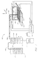
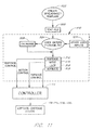
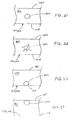
- FIG. 1 is a simplified overview which illustrates one embodiment of a dispensing apparatus 108 having certain features and advantages in accordance with the invention.
- the dispensing apparatus 108 is particularly adapted for automated high-speed precision dispensing (and aspirating) of liquids such as chemical and biological reagents, for example, DNA, cDNA, RNA, proteins, peptides, oligonucletides, other organic or inorganic compounds, among others.
- the dispensing apparatus 108 (FIG. 1) generally comprises a dispensing head or dispenser 128 having a valve or other dispensing means 204 operated by an actuator, such as a solenoid.
- the dispenser 128 is hydraulically coupled or in fluid communication with a positive displacement pump 120 for metering precise quantities of fluid or liquid 130 to or towards the dispenser 128.
- the dispenser 128 is mounted on or in association with an X-Y table or gantry 110.
- a substrate or target 111 is mounted on a carrier platform, table or carriage 112 to receive reagent or liquid dispensed from the dispenser 128.
- the target 111 can comprise one or more microtiter plates, glass slides, receptive membranes, test strips, or other suitable porous or non-porous targets such as one or more single-well receptacles, vials or tubes.
- the microtiter plates can be configured in 96, 384, 1536 and 2080 well plate formats, among other configurations.
- the X-Y table 110 may include one or more position stepper motors 123, 124 or the like, which are operable to move either the dispenser 128 and/or the carrier platform or table 112 relative to one another in the X, X-Y or X-Y-Z directions, as indicated in the drawing.
- one or more suitable robot arms may be efficaciously used, as needed or desired, to provide controlled relative motion between the dispenser 128 and the target substrate 111 and/or other components or associated components of the apparatus 108.
- FIG. 1 shows only a single dispenser 128 , in other preferred embodiments and as discussed further below, it is contemplated that multiple dispensers in linear (1 x N) or two-dimensional (M x N) arrays are used. These may be provided and operated either in parallel or in another coordinated fashion, as desired. It should be understood that any discussion herein with specific reference to the single dispenser embodiment is substantially equally applicable, with passible modifications as apparent to the skilled artisan, to multiple dispensers each connected to respective pumps or a single pump.
- the positive displacement pump 120 ( FIG. 1 ) preferably comprises a syringe pump though other direct current (DC) fluid sources may be used with efficacy.
- the syringe pump 120 is hydraulically coupled to or in fluid communication with a fluid reservoir 116 through a first one-way check valve or open-close valve 145a.
- the syringe pump 120 draws fluid 130 from the fluid reservoir 116 and provides it to the dispenser 128 through a second check valve or open-close valve 145b on a supply line or feedline 150, as shown in FIG. 1.
- the syringe pump 120 (FIG. 1) has a movable piston 118 within a syringe barrel 362 .
- the syringe pump 120 is operated by a syringe pump driver 142 comprising, for example, a stepper motor and an associated lead screw, for extending and retracting the piston 118 within the syringe barrel 362.
- a syringe pump driver 142 comprising, for example, a stepper motor and an associated lead screw, for extending and retracting the piston 118 within the syringe barrel 362.
- fluid 130 is forced to flow from the syringe barrel 362 into the dispenser 128 via the supply tube 150 , whereupon it is ejected by the dispenser 128 onto or into the target substrate 111 in the form of droplets 131 or a spray pattern.
- the fluid or liquid 130 comprises the reagent that is dispensed onto or into the target 111. That is the system (reservoir 116, pump barrel 362, dispenser 128 and other connection lines) is filled with the reagent 130 to be dispensed. This set-up is particularly advantageous when relatively large quantities of the same reagent are to be dispensed.
- the fluid or liquid 130 comprises a system fluid or backing reagent, such as distilled water, and the dispensing apparatus 108 operates in a "suck-and-spit" mode.
- the dispenser 128 is used to aspirate a predetermined amount of fluid, liquid or reagent from a source receptacle or microtiter plate and the like and then dispense the aspirated reagent onto or into the target 111.
- reagent is aspirated by retracting or decrementing the pump piston 118 with the valve 145b open to create a reduced pressure or partial vacuum to draw source reagent into the dispenser 128 via a suitable tip or nozzle thereon.
- a controller 114 oversees operation of the pump 120 , X-Y table 110 (or X, or X-Y-Z table) and the dispenser 128 , among other associated components.
- the controller 114 coordinates and controls the motion of each of the stepper motors 123, 124, and the syringe pump driver 142, as well as the opening and closing of the dispensing valve 204 to precisely dispense an amount of reagent at one or more predetermined location(s) on or in the target substrate 111.
- the controller 114 also controls and coordinates aspiration of source reagent, as and if needed.
- a computer software program is interfaced with the controller 114 ( FIG. 1 ) to guide dispensing (and/or aspirating) for different modes of operation and different applications.
- a user-defned text file is created, for example, from a spreadsheet of values or template, with lists of numbers of user-defined dispense volumes of one or more reagents and corresponding coordinates of the dispense (and/or aspirate) operation.
- the controller 114 uses this text file data in cooperation with the software program to precisely control and coordinate the operation of the dispensing apparatus 108 .
- the use of such text file control allows high-speed precision dispensing of one or more reagents with a wide dynamic range of dispense volumes in complex combinatorial patterns, ratios and arrays onto or into multiple predetermined locations of a desired target or substrate.
- This is particularly advantageous when a large number of permutations of different reagent and permutations of reagent volume ratios are involved.
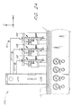
- typically, more than one dispenser (see FIGS. 2A and 2B ) or a manifold system (see FIG. 2C ) or a combination thereof is utilized to facilitate process efficiency.
- These multiple dispensers can be operated in parallel or in synchronous coordination.
- FIG. 2A is a simplified view of a dispensing apparatus 108a comprising a plurality of dispensers 128 .
- each dispenser 128 is connnected to a respective pump 120 (in FIG. 2A , the pumps 120 are part of a pump bank 120a and a reservoir bank 116a comprises the reservoirs 116 ).
- a single reagent may be dispensed by all of the dispensers 128 or multiple reagents, as needed or desired.
- reagent(s) can be first aspirated and then dispensed, as discussed above.
- relative motion is provided between the substrate or target 111 and the dispensing channels 128 .
- the dispensers 128 and/or the platform 112 are movable in the X, X-Y or X-Y-Z directions to allow for precision dispensing at predetermined locations. Multiple targets 111 may be placed on the table 112 , as needed or desired.
- the dispensers 128 can be independently moved or together in the form of a dispense head comprising multiple dispense channels 128 paced from one another by predetermined distance(s). Moreover, the dispensers 128 can be individually (serially or sequentially) operated or substantially simultaneously (parallely) or a combination thereof, as needed or desired.
- a central or main controller possibly in conjunction with sub-controllers, is used to control and coordinate the actuations of the pumps 120, dispensers 128 and relative movement between the target 111 and dispense channels 128.
- FIG. 2B is a schematic view of a dispensing apparatus 108b comprising a plurality of dispensers 128 .
- the dispensing apparatuses described herein can comprise one or more dispensers 128 arranged in a wide variety of configurations such as linear (1 x N), two-dimensional (M x N) or even three-dimensional (M x N x K) arrays.
- the array or collection of dispensers or dispenser heads 128 may be referred to as a "dispensing head" comprising multiple dispense channels 128.
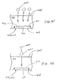
- FIG. 2C is a simplified view of a dispensing apparatus 108c comprising a manifold 109 connected to a plurality of dispensers 128 .
- the manifold generally comprises a main supply line 113 in fluid communication (hydraulically coupled) with a plurality of independent channels 115 each of which is in fluid communication (hydraulically coupled) with a respective one of the dispensers 128.
- a positive displacement syringe pump 120 is in fluid communication (hydraulically coupled) with the manifold 109 via the feedline 150.
- Reagent(s) can be first aspirated and then dispensed or a single reagent may fill the system, as discussed above.
- relative motion is provided between the substrate or target 111 and the dispensing channels 128 .
- the dispensers 128 and/or the platform 112 are movable in the X, X-Y or X-Y-Z directions to allow for precision dispensing at predetermined locations.
- Multiple targets 111 may be placed on the table 112 , as needed or desired.
- the dispensers 128 are in the form of multiple dispense channels spaced from one another by predetermined distance(s). More than one manifold may be utilized, as needed or desired.
- the dispensers 128 can be individually (serially or sequentially) operated or substantially simultaneously (parallely) or a combination thereof, as needed or desired.
- a linear (1 x N) or two-dimensional (M x N) array of dispensers 128 may be used with efficacy.
- a central or main controller 114 is used to control and coordinate the actuations of the pump 120, dispensers 128 and relative movement between the target 111 and dispense channels 128.
- Certain embodiments of a multi-channel aspirate-dispense system comprising a manifold are described in copending U.S. Patent Application No. 09/372,719, filed August 11, 1999, entitled MULTI-CHANNEL DISPENSING SYSTEM, the entirety of which is hereby incorporated by reference herein.
- the use of a manifold 109 allows only one pump 120 to meter fluid to and from a plurality of dispensers 128 . Desirably, this saves on cost. Moreover, balanced and controlled output can be achieved by adjusting the frequency and/or duty cycle of one or more of the dispensers 128 to compensate for any variations in flow resistances between channels.
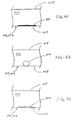
- FIG. 3A is a cross-sectional view of one embodiment of a solenoid valve dispensing head 128 for use with the dispensing (and/or aspiration) systems as described herein.
- Solenoid valve dispensers of the type shown in FIG. 3A are commonly used for inkjet printing applications and are commercially available from sources such as The Lee Company of Westbrook, Connecticut. Other suitable drop-on-demand dispensers and valves may be efficaciously used, as needed or desired.
- the drop-on-demand dispenser 128 ( FIG. 3A ) generally comprises a solenoid portion 202 , a valve portion 204 and a tube, capillary, tip or nozzle portion 205 .
- the solenoid portion 202 and the valve portion 204 in combination can be termed a drop-on-demand valve, a solenoid-actuated valve or a micro-solenoid valve 203.
- the solenoid portion 202 (FIG. 3A) comprises an electromagnetic coil or winding 206 , a static core 238 and a movable plunger 240 .
- Tne static core 238 and movable plunger 240 are disposed within a hollow cylindrical sleeve 241 and are preferably spaced at least sligbdy away from the inner walls of the sleeve 241 so as to form an annular passage 242 there between through which the reagent 130 or other liquid to be dispensed may flow.
- the static core 238 and movable plunger 240 are preferably formed of a ferrous or magnetic material, such as an iron alloy, and are separated by a small gap 244 .
- the valve portion 204 (FIG. 3A) comprises a valve seat 252, having an orifice opening 254, and a stopper 256 having a valve face 258 adapted to seal against the valve seat 252.
- the stopper 256 is in electro-mechanical communication with the plunger 240 and is spring biased toward the valve seat 252 via coil spring 260 .
- the valve 234 will open and close, accordingly, hence providing selective fluid communication with the tip 205.
- a volume of liquid is allowed to escape through the valve orifice 254. This, in conjunction with the metering of fluid by the pump 120, forms an energy pulse or pressure wave which causes a droplet of liquid to be ejected from the exit orifice 261 of the nozzle tip 259.
- the pump 120 is a positive displacement pump and is provided in series with the solenoid valve dispenser 128.
- Configuring the dispensing system in this manner has the benefit of forcing the solenoid valve dispenser 128 to admit and eject a quantity and/or flow rate of reagent as determined solely by the positive displacement pump 120, with which it is hydraulically in series.
- the syringe pump could be instructed to deliver a flow rate of 1 microliter per second of reagent to the solenoid valve dispenser 128 at a steady rate.
- the valve stopper 256 is opened and closed at a given frequency and duty cycle a series of droplets are formed which will exactly match the desired flow rate.
- the syringe pump acts as a forcing function for the entire system, ensuring that the desired flow rate is maintained regardless of the duty cycle or frequency of the dispensing valve.
- the frequency and/or velocity of the droplets can be adjusted without affecting the flow rate of reagent simply by changing the frequency aud/or duty cycle of the energizing pulses 182 ( FIG. 1 ) provided to the solenoid valve dispenser 128 .
- the frequency aud/or duty cycle of the energizing pulses 182 FIG. 1
- dispensers and valve actuation devices exist and may be used with efficacy. These may include, for example, but are not limited to piezoelectric dispensers, fluid impulse dispensers, heat actuated dispensers, air brush dispensers, and the like.
- FIG. 3B shows a cross-sectional view of a piezoelectric dispenser 128' which also has advantageous use in accordance with embodiments of the invention.
- the piezoelectric dispenser 128' generally comprises a capillary tube 270 made of glass or other suitable material and a piezoelectric constrictor 272 disposed around the capillary tube 270, as shown.
- the capillary tube 270 has a nozzle portion 274 of a reduced diameter.
- droplets 276 are formed at the exit orifice 278 of the nozzle portion 274.
- the dynamics of the piezoelectric dispenser 128' are such that it may be able to operate at even higher frequencies and shorter duty cycles than typical solenoid valve dispensers, resulting in even smaller droplets 276.
- Operation of the piezoelectric dispenser 128' in terms of adjusting droplet size, frequency, velocity and flow rates is substantially the same or similar to that described in connection with the solenoid valve dispenser 128 of FIG. 3A and, therefore, will not be repeated here.
- FIGS. 3C, 3D and 3E show different views of a non-contact dispensing capillary tip or tube 1000 having features and advantages in accordance with one embodiment of the invention.
- the dispensing tip 1000 may be incorporated into any of the dispensing systems taught or suggested herein such as the embodiments of FIGS. 1, 2A-2C and 3A-3B .
- Embodiments of such tips are disclosed in U.S. Patent Application No. 09/459,245, filed December 10, 1999, and International Application No. PCT/US99/15214, filed July 7, 1999, International Publication No. WO 00/01798, published January 13, 2000, both entitled TIP DESIGN AND RANDOM ACCESS ARRAY FOR MICROFLUIDIC TRANSFER, the entirety of each one of which is hereby incorporated by reference.
- the tip 1000 is generally cylindrical in shape and comprises a non-tapered upper portion or shank 1002 with an upper end 1003, a tapered lower portion/outer surface 1004 with a lower end 1005 and an inner lumen or through cavity 1006.
- the inner lumen 1006 is generally cylindrical in shape with a top opening 1008, a non-tapered upper portion 1010, and a tapered lower portion/inner surface 1012 to form a nozzle 1014 having an orifice or opening 1016.
- the outer taper 1004 leads to less accumulation of fluid on the tip outer surface, for example, during aspiration.
- the inner taper 1012 is a desirable shape for capillary action, and reduces fluid mixing during aspiration and reduces the precipitation of gaseous bubbles within the fluid during aspirate-dispense operations.
- the tip 1000 may further include a generally circumferential groove, slot or notch 1018 on the non-tapered upper portion 1002.
- the slot 1018 is generally V-shaped.
- the notch 1018 advantageously provides an easy break point in the case of accidental hard or jarring contact between the tip 1000 and a contacting surface of the fluid source or target.
- the tip 1000 (FIGS. 3C-3E) is fabricated from a ceramic material, and more preferably, from alumina.
- the ceramic material provides chemical inertness since alumina is inert to most chemical solvents.
- the ceramic material provides robustness, and hence can withstand extreme mechanical stress.
- the tip 1000 can be fabricated from a wide variety of materials with efficacy such as metals, alloys, and plastics, as required or desired, giving due consideration to the goals of providing chemical inertness and robustness.
- the outer surface 1019 ( FIG. 3C ) of the tip 1000 is coated with a thin film or coating that is not only chemically inert and mechanically robust but is also hydrophobic to most fluids such as aqueous reagents, DMSO, and other common solvents.
- the film helps in keeping the tip 1000 dry and also proves the microfluidic or sub-microfluidic transfer.
- the film comprises a wear-resistant material so that it has an enhanced lifetime.
- Suitable films or coatings include silicon nitride, silicon carbide, titanium nitride, among others.
- the film or coating can be applied by a variety of methods as plasma deposition and sputtering, among others, as is known in the art.
- a suitable hydrophobic coating may also be applied to selected portions of the inner surface 1021 of the tip 1000 , as needed or desired.
- the tip 200 may be dimensioned in a wide variety of manners with efficacy, as required or desired, giving due consideration to the goals of providing reliable and repeatable microfluidic and sub-microfluidic transfer of fluid.
- the tip 200 has a length of 16 mm and an internal volume of about 20 microliters ( ⁇ L).
- the inner diameter at the nozzle end of the tip 200 is in the range from about 20 to 180 microns ( ⁇ m) and the outer diameter is in the range from about 50 to 400 ⁇ m or more.
- the inner diameter at the nozzle end of the tip 200 is in the range from about 100 to 300 ⁇ m and the outer diameter is in the range from about 400 to 900 ⁇ m.
- the pump 120 is preferably a high-resolution, positive displacement syringe pump hydraulically coupled to the dispenser 128.
- pump 120 may be any one of several varieties of commercially available pumping devices for metering precise quantities of liquid.
- a syringe-type pump 120 as shown for example in FIG. 1, is preferred because of its convenience and commercial availability.
- a wide variety of other direct current fluid source means may be used, however, to achieve the benefits and advantages as disclosed herein. These may include, without limitation, rotary pumps, peristaltic pumps, squash-plate pumps, and the like, or an electronically regulated fluid current source.
- a suitable syringe pump 120 generally comprises a syringe housing 362 of a predetermined volume and a plunger 118 which is sealed against the syringe housing by O-rings or the like (not shown).
- the plunger 118 mechanically engages a plunger shaft 366 having a lead screw portion 368 adapted to thread in and out of a base Support (not shown).
- a pump driver 142 including a stepper motor ( FIG. 1 ) or other incremental or continuous actuator device is used so that the amount and/or flow rate of reagent 130 can be precisely regulated.
- syringe pumps are commercially available.
- One such syringe pump is the Bio-Dot CV1000 Syringe Pump Dispenser, available from BioDot, Inc. of Irvine, California.
- This particular syringe pump incorporates an electronically controlled stepper motor for providing precision liquid handling using a variety of syringe sizes.
- the CV1000 is powered by a single 24 DC volt power supply and is controlled via an industry-standard RS232 or RS485 bus interface.
- the syringe pump may have anywhere from 3,000-24,000 steps, although higher resolution pumps having 48,000-192,000 steps or more may also be with efficacy. Higher resolution pumps, such as piezoelectric motor driven pumps, may also be used to provide even finer resolutions as desired.
- the lead screw 368 may optionally be fitted with an optical encoder or similar device to detect any lost steps.
- the lead screw of the metering pump can be replaced with a piezoelectric slide to provide both smaller volume increments and also faster acceleration/deceleration characteristics.
- Multiple syringe pumps may also be used in parallel, for example, for delivering varying concentrations of reagent 130 and/or other liquids to the dispenser or for alternating dispensing operations between two or more reagents. This could have application, for instance, to ink jet printing using one or more colored inks or liquid toners.
- Syringe size may vary from less than 50 microliters ( ⁇ L) to 50 milliliters (mL), or more as needed.
- the minimum incremental displacement volume of the pump will depend on the pump resolution and syringe volume. For example, for a syringe housing volume of 50 ⁇ L and 192,000 step resolution pump the minimum incremental displacement volume will be about 0.260 nanoliters (nL). Minimum incremental displacement volumes from about 0.25 nanoliters to about tens of milliliters (mL) are preferred, although higher or lower incremental displacement volumes may also be used while still enjoying the benefits disclosed, taught or suggested herein.
- one or more pressure sensors 151 are provided in conjunction with the aspirate-dispense apparatuses 108 (FIG. 1), 108a (FIG. 2A), 108b (FIG. 2B) and 108c (FIG. 2C) to monitor the system pressure and provide diagnostic information about various fluid and flow parameters within the hydraulic system.
- the one or more pressure sensors 151 are provided at appropriate locations on the respective systems.
- the pressure sensors 151 are placed intermediate the syringe pump(s) 120 and the dispenser(s) 128, such as on the feedline 150 (see, for example, FIG. 1).
- the pressure sensor(s) 151 can be situated at the dispenser(s) 128 such as on the valve portion(s) 204.
- the hydraulic coupling between the pump 120 and the dispenser 128 of the aspirate-dispense system 108 provides for the situation where the input from the pump 120 exactly equals the output from the dispenser 128 under steady state conditions. Therefore, the positive displacement system uniquely determines the output volume of the system while the operational dynamics of the dispenser 128 serve to transform the output volume into ejected drop(s) having size, frequency and velocity.
- a positive displacement pump 120 in series with a dispenser 128 (FIG. 1) has the benefit of forcing the dispenser 128 to admit and eject a quantity and/or flow rate of reagent as determined solely by the positive displacement pump 120 for steady state operation.
- the syringe pump 120 acts as a forcing function for the entire system, ensuring that the desired flow rate is maintained regardless of the duty cycle, frequency or other operating parameters of the dispensing valve, such as the solenoid-actuated valve 128 (FIG. 3A) .
- the solenoid-actuated valve 128 FIG. 3A
- the trsnsitions between various modes (aspirate, dispense, purge/wash) and/or flow rates or other operating parameters can result in pressure transients and/or undesirable latent pressure conditions within the positive displacement dispense/aspirate system.
- Purge and functions usually entail active dispensing in a non-target position. In some cases, when the same reagent is to be aspirated again, several aspirate-dispense cycles can be performed before executing a purge or wash function. Also, sometimes a purge function may have to be performed during a dispense function, for example, to alleviate clogging due to the precipitation of gaseous bubbles within the system and/or source fluid. Moreover, the accumulation of these bubbles can change the system compliance over time, and hence the desired optimum dispensing pressure.
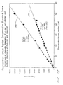
- line 910 in FIG. 5 illustrates transient dispense effects caused by initial start-up of a dispensing system 108 (FIG. 1) in which no pressure compensation scheme is utilized.
- the x-axis 903 represents the dispense number or number of dispenses and the y-axis 902 represents the dispense volume, in nanoliters (nL) of each droplet or droplets dispensed.
- Line 914 in FIG. 5 represents the target dispense volume of 100 nL.
- the non-pressure compensated (non-steady state) dispensed volume represented by line 910 is substantially smaller than the target dispense volume of 100 nL (line 914) since the system pressure at start-up is substantially lower than the desired steady state and/or predetermined pressure.
- the non-pressure compensated dispense volume (line 910 ) can be lower by a factor of about ten compared to the target dispense volume (line 914 ). Moreover, even after 23 dispenses (see FIG. 5 ) the dispensed volume (line 910 ) is still below the target volume (line 914).
- Line 912 represents a series of about 100 nL dispenses performed in accordance with one embodiment, wherein an optimized pressurizing (300 steps of the syringe plunger 118 -- shown in FIGS. 1 and 4 ) is performed prior to dispensing, that is, with the valve 204 ( FIGS. 1 and 3A ) closed.
- the pressure compensation scheme provides dispense volumes (line 912 ) which are in substantially close conformity with the target dispense volume (line 914 ) of 100 nL.
- Under-pressurization 200 steps of the syringe plunger 118
- over-pressurization 400 steps of the syringe plunger 118
- the syringe plunger 118 (FIGS. 1 and 4) is typically incremented (or possibly decremented) by a predetermined amount to build up (or reduce) pressure, as described above in connection with FIG . 5 .
- the syringe plunger 118 (FIGS. 1 and 4 ) is typically decremented (or possibly incremented) by a predetermined amount.
- pre-dispenses of reagent or system fluid in a waste position may be performed to raise or lower the system pressure, as needed or desired.
- One or more pressure sensors such as the pressure sensor(s) 151 (FIGS. 1, 2A, 2B and 2C) are used to monitor the system pressure and ensure that the correct operational pressure(s) are achieved. Any one of a number of commercially available pressure sensors may be efficaciously used.
- the pressure sensors 151 are preferably differential type devices.
- the desired steady state dispense pressure can be estimated from flow resistances and/or prior steady state pressure measurements or transient pressure measurements. A number of parameters can affect the selection of this pressure, including the desired droplet volume and system compliance, among other fluid, flow, system and operational parameters.
- the steady state pressure can also be estimated from previously formulated parametric tables or charts based on one or more fluid, system, flow and operational parameters. Regression analysis techniques may be used to estimate the optimum dispense pressure. Alternatively, or in addition, the dispense pressure may be predetermined for a given production set-up.
- the aspirate-dispense systems disclosed herein are configured to minimize the formation and accumulation of gaseous bubbles within the fluid residing in the system, and particularly in the dispensers 128 ( FIGS. 1, 2A, 2B and 2C ), feedline 150 and manifold 109 ( FIG. 2C ).
- the system components be configured such that the fluid movements within the system avoid sharp local pressure drops, and hence gaseous bubble precipitation.
- the components may be configured such that none or few "dead spots" are encountered by the fluid, thereby discouraging bubble accumulation within the system.
- These configurations can utilize suitably tapered inner cavities or lumens within the valve portion 204, tip 205 and/or nozzle 259 to provide relief from gaseous bubble precipitation and/or "dead spots.”
- a suitably configured bubble trap (not shown) is provided in fluid communication with the dispenser 128 (see, for example, FIG. 1 ).
- the trap encourages the migration of gaseous bubbles to collect within the trap and prevents undesirable bubble accumulation within the aspirate-dispense system.
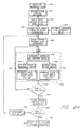
- the dispensing operation takes place on-the-fly, that is without stopping the motion of the X-Y table.
- the controller 114 calculates a phase adjustment for each dispense cycle.
- the phase adjustment is such as to advance (or retard) the timing of the valve opening and closing so that the dispensed droplet of reagent lands at the desired location on the substrate 111 (or at a desired offset location), taking into account its anticipated trajectory.
- the magnitude of the necessary or desired phase adjustment will depend, among other things, on a number of system input and output parameters and behavioral characteristics, including the desired drop offset (if any), the vertical distance between the dispenser nozzle 205 and the surface of the substrate 111 , the velocity and/or acceleration of the dispenser 128 and/or the substrate 111 relative to one another, the velocity of the dispensed droplets, ambient temperature and humidity, and other controlled and/or uncontrolled factors. While certain of these parameters or characteristics can be isolated and studied such that their impact on the necessary phase adjustment is fairly predictable, other parameters or characteristics can neither be isolated nor predicted. It is however contemplated, that precise phase adjustments can be determined experimentally for a given production set up either before or during production such that a high degree of accuracy, precision and repeatability is attained during long production runs.
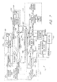
- FIG. 7 illustrates one possible embodiment of an electronic controller 114 for controlling and coordinating the operation of the aspirate-dispense apparatus 108 ( FIG. 1 ).
- this controller design is extendable and/or adaptable to control and coordinate the operations of systems comprising multiple pumps 120 and cooperating dispensers 128, as shown for example in FIGS. 2A and 2C , and/or systems comprising a manifold intermediate a single pump 120 and multiple dispensers 128 , as shown for example in FIG. 2C.
- the controller 114 should be construed in light of possible modifications and equivalents.
- the controller 114 ( FIG. 7 ) generally comprises a host CPU 402 or computer which interfaces with some form of data memory.
- the controller may be roughly divided into five basic subsystems: host CPU 402, coordinate control circuitry 404 , memory and logic circuitry 406, syringe stop count circuit 408 , and valve firing circuit 412. Each of these subsystems are illustrated schematically by phantom lines in FIG. 7 and are described in more detail below.
- each subsystem works in cooperation with the other subsystems to simultaneously control the coordinate stepper motors 123, 124 ( FIG. 1 ) the syringe pump motor 142 ( FIG. 1 ) and the solenoid valve dispenser 128 ( FIG. 1 ) to achieve the desired operation.
- the controller 114 is further adapted to control aspiration of fluid, perform wash/purge operations and refill the system with fluid from the reservoir 116 (FIG. 1) , as needed or desired.
- a host CPU 402 serves as the central controller and also the interface between the controller 114 and the user. It allows the operator to input dispensing, aspirating, motion and/or other operational data, preferably in the form of a user-defined "Text File", as discussed in greater detail below.
- the CPU 402 allows the user to control, either independently or simultaneously, each aspect of the dispensing and aspirating apparatus 108 ( FIG. 1 ).
- the host CPU 402 generally comprises a 80x86 or Pentium-based computer having a slot or bus compatible to accept a plug-in circuit board.
- the circuit board or "controller card” contains the four subsystems shown in FIG. 7.
- the controller card mounts or plugs into a computer bus providing data transfer and communication of instructions.
- the host CPU 402 also provides power to the controller card and further allows an operator to access, program and control the functions of the controller card. It is further contemplated that the host CPU 402 contains suitable computer software compatible with the host CPU and the controller card which facilitates operation of the system as described herein.
- a display device and data input means are integral with the host CPU 402 thereby providing means to input data into a memory or static RAM array 414 located on the controller card and to verify the same using the display device.
- a keyboard, mouse, trackball, light pen, capacitance touch screen, computer storage media are all acceptable data input means.
- a color video monitor or screen provides a suitable display means.
- a data entry device such as a keyboard
- an operator may enter data into the host CPU 402 in the form of a data array (or graphical bit map) to thereby instruct the electronic controller and dispensing apparatus of the desired reagent pattern and characteristyes.
- Conventional computer software may facilitate the entry of the data array (or bit map) via the host CPU 402 to the memory 414 of the controller card.
- a user-defined text file is used to provide input data to the controller 114 (FIG.7).
- the controller card is compatible with a PC-AT clone, i.e. 80x86 or Pentium-based architecture.
- the controller card form factor and bus configuiafion match a PC-104 format, thereby allowing the circuit design to be quickly and inexpensively manufactured in a circuit board format.
- the host CPU 402 utilizes a Motorola 68332 processor as the main microprocessor. However, as known by those skilled in the art, other computer systems and host CPU's may be used with equal advantage.
- a bus generally comprises an electrical connection which facilitates the exchange of information, such as address information, data information and/or instructions.
- the controller 114 (FIG. 7) includes an address bus 416 which carries address information, and a data bus 418 which carries data information.
- the data bus 418 and the address bus 416 connect to the memory and logic circuitry 406.
- the data bus 418 and the address bus 416 are bi-directional thereby allowing the transfer of data between the controller card and the memory and logic circuitry 406.
- the controller 114 may display status information from the controller card on the video display of the host CPU 402 or alternatively, write the information to a data file on a permanent storage medium.
- other types of electrical connections exist which carry electronic information and are fully contemplated for use with the embodiments disclosed, taught or suggested herein.
- the memory and logic circuitry 406 stores the data which defines the desired dispensing and aspiration pattern and characteristics. As described in further detail below, preferably, a user-defined text file is used to provide operational data to the controller 114 (FIG. 7 ).
- Other hard-wired logic circuitry such as a counter 424 and multiplexer 426, may also be used, as desired, to parse dispensing data to the other subsystems of the controller 114 or to speed up the processing of information and control data.
- the memory and logic circuitry 406 (FIG. 7) generally comprises an electronic memory 414 for storing data regarding reagent disperse, aspirate and motion parameters, a tri-state buffer 420 , a divisor 422, an address counter 424, a multiplexer 426 and various logic circuitry to assure proper operation of the electronic controller 114.
- the tri-state buffer 420 connects to the host CPU 402 via the data bus 418 and serves to isolate the CPU from the controller card.
- the buffer is adapted to rapidly accept and store data to further increase data transfer speed and free the host CPU 402 of data transfer operations.
- the tri-state buffer 420 connects to the memory module 414, preferably static ram array.
- the buffer 420 also connects to the output lines of the static ram array 414 for direct control of the syringe motor 142 (FIG. 1) and the solenoid valve dispenser 128 (FIG. 1).
- the static ram array 414 (FIG. 7) comprises an electronic memory device which stores the data in the form of a data array sent from host CPU 402 via the tri-state buffer 420.
- the data array 414 defines the reagent dispensing and/or aspiration pattern, preferably, provided at least in part by a text file, as discussed below.
- access to each value in the data array 414 corresponds to a data array address thereby allowing access to specific data in the data array.
- a 2:1 multiplexer 426 ( FIG. 7 ) connects via the address bus 416 to the host CPU 402.
- the 2:1 multiplexer 426 allows the operator to select which of the two inputs pass to the output.
- the multiplexer 426 has two inputs: a first input which connects to the output of the counter 424 and a second input which connects to the address bus 416.
- the multiplexer 426 provides a data array address from the host CPU 402 or, during steady state operation, from the output of the memory and logic circuitry counter 424 .
- the multiplexer 426 passes the counter output to the static RAM array 414, the address increments automatically by way of a stepper control chip output.
- the output of the stepper control chip 430 advantageously serves as the main clock for the controller and thereby synchronizes operation of the system 108. A more detailed discussion of the stepper control chip 430 is provided below.
- the counter output 424 (FIG. 7) provides one of the two inputs to the multiplexer 426 .
- a counter 424 comprises digital logic circuit which records input pulses to produce a binary word that increases or decreases in value by a predetermined number (preferably 1) upon each input pulse. This binary word provides the next address for retrieving data from the data array and/or directly from a user-defined text file. Thus, the counter 424 operates to increment the address of the data array 414.
- the counter 424 is preferably a resettable circuit and a reset line 425 is provided from the miscellaneous register and logic 428 to reset the counter 424 .
- the counter 424 may also be reset either automatically or manually via an interrupt (not shown) from the host CPU 402.
- the output of divisor circuitry 422 provides input to the counter 424.
- the divisor 422 provides an output after receiving N number of input pulses, where N is the number of input pulses required to trigger an output pulse.
- the divisor 422 can be user adjustable so that the value for N may be set by the operator.
- the resolution of the dispensing apparatus may be controlled by the number of pulses output by the stepper control chip 430 and the value assigned to N.
- a divisor 422 can readily be implemented using a form of a counter circuit wherein the counter circuit outputs a pulse upon receipt of a certain number of input pulses.
- the input to the divisor 422 is the main clock signal provided by the stepper control chip 430.
- the divisor circuit 422 also provides output to the syringe stop count circuit 408 and the valve firing circuit 412, described below.
- Dual output lines from the static ram array 414 connect to each of the syringe stop count circuit 408 and the valve single shot circuit 412, both of which are described in more detail below.
- the output of the static ram array 414 defines the desired syringe motor increment and the valve pulse duration and is sequentially incremented by the address counter input.
- miscellaneous registers and logic are integral with the above described componentry.
- various logic circuitry and storage registers 428 are interspersed with the componentry described herein as appropriate.
- much of the electronic hardware described herein could be embodied through the use of suitable software, as desired or appropriate.
- Coordinate control circuitry 404 moves the dispensing head 128 (FIG. 1) to each desired and/or predetermined location. While FIG. 7 only shows circuitry for X axis motion control, those skilled in the art will readily appreciate that Y axis motor control is also contemplated in embodiments of the invention to facilitate operation with an X-Y table. In another embodiment, the controller 114 may also incorporate Z axis motion to achieve compatibility with an X-Y-Z table. This provides additional control of the system by providing means to vary the distance between the dispensing head 128 and the substrate 111 (FIG. 1) . Also, one of both of the dispenser 128 and substrate may be movable in the X, X-Y or X-Y-Z. Furthermore, as indicated above, relative movement may be provided for the embodiments of FIGS. 2A-2C.
- the coordinate control circuitry 404 (FIG. 7) generally comprises a stepper control chip 430, control logic 446 and an axis motor driver 448. As discussed in greater detail below, the coordinate control circuitry 404 provides input to the divisor 422 of the memory and logic circuitry 406. The coordinate control circuitry 404 also provides control of an axis stepper motor 123 ( FIG. 1 ) and input to the syringe stop count circuit 408 and the valve firing circuit 412.
- the stepper control chip 430 (FIG. 7) generates a constant step pulse output. This step pulse output serves dual purposes. First, the step pulse provides a control signal to the axis motor drive 443 which in turn powers the stepper motor 123. The stepper motor controls the dispensing head position along the X-axis. Second, the step pulse, or a divided form thereof propagates throughout the system as the main clock pulse.
- the stepper control chip 430 is of the type often used to operate stepper motors.
- One embodiment described herein utilizes a Nippon Pulse PCL-240AK available from the Nippon Pulse Motor Co., Ltd, although other stepper motor control chips are currently available and are operational with the embodiments disclosed herein.
- the stepper control chip 430 has two outputs: a step pulse output 450 and a direction signal output 452.
- the first output, the step pulse output 450 connects to at least one logic device to regulate the operation of the step motor 123.
- the logic device comprise a dual-input AND gate 446.
- One input of the AND gate 446 connects to the step pulse output 450 from the stepper control chip 430.
- An axis enable line 453 connects to the other input of the AND gate 446.
- the axis enable signal when high, allows the step pulse output to propagate to the output of the AND gate 446.
- the memory and logic circuitry 406, described above, provides the axis enable signal to the AND gate 446 thereby providing means to cease movement of the dispensing head 128, either automatically via the data array or manually via the host CPU 402.
- the second output of the stepper control chip 430 ( FIG. 7 ), the motor direction control signal, is provided on a direction control line 452 to control the direction of the X axis stepper motor 123.
- the motor direction line 452 which carries the motor direction signal, connects directly to the axis motor driver 448 .
- the stepper motor direction signal is also fed to the syringe stop count circuit 408, described in more detail below. Changing the state or logic level of the direction line, changes the direction of the X-axis stepper motor 123. This advantageously provides for bi-directional printing which, as noted above, speeds dispensing operation.
- An axis motor driver 448 receives the output from the AND gate 446 and the stepper control chip 430.
- the axis motor driver 440 is an electronic device controlled by normal logic level signals which correlates the logic level input signals into a specialized output having increased current sourcing ability to drive a stepper motor. As is known by those of ordinary skill in the art many different axis motor drivers are available which satisfy the needs of the current invention.
- the output of the axis motor driver 448 (FIG. 7) is provided to the X-axis stepper motor 123 (FIG. 1).
- the stepper motor 123 controls movement of the dispensing head 128 in relation to the substrate 111 (FIG. 1).
- the stepper control chip 430, axis motor driver 448, and stepper motor 123 have resolution of greater than about a hundred steps per linear inch, more preferably greater than about five hundred steps per linear inch, even most preferably greater than about seven hundred fifty steps per linear inch.
- the syringe stop count circuit 408 (FIG. 7) controls the syringe pump 120 (FIG. 1) based on signals received from the stepper control chip 430 and the memory and logic circuitry 406.
- the syringe stop count circuit 408 comprises control logic, a syringe circuit divisor 455, a syringe circuit counter 456, and a syringe motor driver 458.
- the syringe stop count circuit 408 is synchronized with the other subsystems of the controller 114 to ensure precise and synchronized control over syringe motor driver 458.
- the control logic provides means to obtain manual control over the syringe and includes a direction control NOR gate 460 which has two inputs, the first of which connects to the direction line 452 of the stepper control chip 430 and the second of which connects to a syringe direction invert line 462 .
- the syringe direction invert line 462 although not shown, connects to the memory and logic circuitry 406 and is discussed in more detail below.
- the output of the direction control NOR gate 460 connects to the syringe motor driver 458 , described below. Based on the signals entering the NOR gate 460 the syringe motor driver can be made to charge the direction of the syringe stepper motor 142 ( FIG. 1 ).
- the syringe motor 142 is bi-directional thereby providing means to draw liquid into the syringe or expel liquid from the syringe 120.
- the syringe direction invert signal may be provided, for example, in accordance with data contained in the static ram array 414 and thus may operate based on initial programming.
- the motion of the syringe plunger 118 (FIG. 1) also reverses direction.
- the values in the static ram array 414 may exist to ensure bi-directional printing, that is, the level of the signal on the direction invert line 462 changes when the direction of the stepper motor 123 changes.
- aspiration, dispensing and filling of the syringe 120 are all automatically controlled via the controller 114 , associated software and user-defined inputs.
- an operator may manually control the direction of the syringe 120 (FIG. 1) through the host CPU 402 via the direction invert line 462.
- Manual control over the syringe 120 provides the operator with the ability to aspirate, dispense or fill the syringe 120 on a non-automated basis, as needed or desired.
- the syringe stop count circuit 408 also contains a syringe circuit counter 456.
- the syringe circuit counter 456 determines the number of pulses to be provided to the syringe motor during a discreet dispense operation.
- the syringe circuit counter 456 has three inputs 465, 466, 467 and an output 464.
- the first input 465 accepts the syringe increment value from the static RAM array 414.
- the syringe increment value is the number of steps the syringe motor 142 (FIG. 1) will move at a particular target location.
- the second input 466 accepts the output of the divisor 422 from the memory and logic circuitry divisor 422.
- the divisor output acts as the main clock for the syringe circuitry counter 456 thereby synchronizing the counter's output to each rising pulse of the divisor output.
- the counter's third input 467 is a tap to monitor the pulses arriving at the syringe motor driver 458 and thereby count down the value at the counter.
- the syringe circuit counter 456 obtains a value from the data array, in this case the number of steps the syringe 120 is to increment, and in response to each upward edge of the main clock signal, provides an equal number of pulses to an output 454 .
- the output 454 ( FIG. 7 ) of the counter 456 feeds to the three part logic network of the syringe stop count circuit 408 .
- the logic network synchronizes operation of the positive displacement pump 120 ( FIG. 1 ) with the position stepper motor 123 and provides manual control, as needed, for a user to inhibit operation of the syringe.
- the logic network comprises a syringe override OR gate 470, an AND gate 471, and a syringe inhibitor AND gate 472.
- the syringe override OR 470 gate has a first input connected to the counter output 454 described above.
- the syringe override OR gate 470 has a second input connected to a syringe override signal line 474, which provides means to manually operate the syringe motor 142.
- the data array in the static RAM array 414 may provide the syringe override signal, or alternatively, in manual control mode, the host CPU 402 may provide the syringe override signal via the memory and logic circuitry 406.
- the output of the syringe override OR gate 470 connects to a first input of an AND gate 471.
- the second input of the AND gate connects directly to the output of the stepper control chip 430.
- the AND gate 471 allows for syringe motor signal propagation from either the syringe override signal or, during automatic operation based on the values from the static ram array 414.
- the output of the AND gate 471 connects to a first input of a syringe inhibit AND gate 472.
- the second input to the syringe inhibit AND gate 472 comprises a syringe inhibit signal line 476, which provides means to cease operation of the syringe motor 142.
- the data array in the static RAM array 414 provides the syringe inhibit signal, or when the dispenser is under manual control, the host CPU 402 provides the syringe inhibit signal.
- the output of the syringe inhibit AND gate 472 enters a syringe circuitry divisor 455.
- the divisor 455 is substantially identical to the divisor described above in the memory and logic circuitry 406, and thus is not described in detail again.
- the divisor 455 provides an output pulse for every N number of input pulses, when N determines the resolution of the system.
- the divisor 455 provides its output to the syringe circuitry counter 467 and the input of the syringe motor driver 458.
- the syringe motor driver 458 (FIG. 7) operates substantially in accordance with the principles of the previously described axis motor driver 448 of the coordinate control circuitry 404 and therefore will not be repeated here.
- Valve firing circuit 412 controls and synchronizes operation of the dispensing head 128 (FIG. 1) in coordination with the remaining subsystems of the dispensing apparatus 108 (FIG. 1).
- the valve firing circuit 412 comprises a valve pulse counter 480, a reference clock 482, and a valve driver 484.
- the valve firing circuit 412 obtains two input signals.
- the first input, from the memory and logic circuitry 406 comprises a valve pulse value from the static RAM array 414.
- the valve pulse value is the time or number of click cycles the valve is to remain open.
- the second input comprises the main clock pulse from the output of the memory and logic circuitry divisor 422.
- the main clock pulse serves to synchronize operation of the valve with the rest of the dispensing apparatus.
- the pulse counter 480 is responsible for providing the proper pulse duration to the valve driver 484.
- valve firing circuitry includes a reference clock.
- the reference clock generates pulses of constant time duration. These pulses of constant time duration provide a known time reference on which the counter may base its operation. Since the valve pulse duration is in units of time, the reference clock 482 ensures accurate operation of the dispensing head or dispenser 128 (FIGS.1 and 3A).
- the output of the pulse counter 480 connects to a valve driver 484.
- the valve driver 484 receives the logic level input from the pulse counter 480 and provides a driving voltage for driving a solenoid or other such device to open and close the valve 204 of the solenoid valve dispenser 128 (FIG. 3A ). Accordingly, the valve driver 484 electrically communicates with the solenoid valve dispenser 128 and solenoid 202 of the valve 203.
- FIG. 8 is a simplified flow chart, in accordance with one embodiment, illustrating the basic operation of a dispenser apparatus and control system as described herein.
- the first step 604 typically comprises providing the reagent pattern and application requirements/parameters to the controller.
- the data is preferably provided or entered in the form of a text file, for example, in table format.
- the data may be in graphic form in a bit map graphic file.
- the reagent application requirements define the location and amount and the application characteristics of the dispensing (and/or aspiration) process. This may be inputted by the operator via a keyboard or graphic interface of it may be loaded directly from a storage media, such as magnetic disk or tape.
- the system translates the application requirements into syringe displacement and valve pulse duration values and anges the calculated values in a data array.
- the data array may contain data values which govern the manner in which reagent is dispensed at a particular target location.
- each data address corresponds to a target location and consequently each target location has a plurality of corresponding values which define the dispensing characteristics for that location.
- similar tables are created for each dispenser.
- the syringe displacement value and the valve pulse value for each dispense location corresponds to an address in the data array.
- the controller 114 moves the dispensing head 128 across the substrate 111, the address in the data array is sequentially incremented thereby progressing through the values in the data array.
- This provides precise control over the amount of reagent and the manner in which the reagent is provided to each location on the substrate 111. In one embodiment, all of this occurs simultaneously (“on-the-fly") with the continuous motion of the dispensing head as it travels across the substrate. In another embodiment, a "move-stop-dispense" approach is utilized.
- Adjustments may include estimated adjustments for fluid viscosity, fluid temperature, dispensing apparatus configuration, substrate composition and other parameters. Adjustments may also include compensation for the velocity of dispensing head for X-axis and/or Y-axis travel. For example, in "on-the-fly" mode, if the dispensing head is moving at a high velocity, the pulsing of the valve and syringe must be phased slightly ahead of the desired dispensing location in order to hit the desired target area given the anticipated trajectory. Likewise, a more viscous liquid may require additional phase adjustments or an increase in the valve pulse time and the syringe increment distance so that the proper amount of reagent exits the valve.
- adjustments may be determined through empirical studies and/or experimentally for a given reagent or production set-up. For example, rough adjustments can be made to the dispense data based on known or determined parametric equations or look-up tables in order to adjust for temperature, viscosity, height or speed of the dispensing head, etc. Finer adjustments can then be made experimentally for a given production set up. This can be done, for example, by programming the dispensing apparatus to dispense known patterns of crossing or parallel lines, target patterns and/or the like, at particular locations on the substrate. By inspecting the resulting patterns, certain adjustments, such as phase lead or lag, can be made to the dispense data to compensate for noted errors. The experiment can be repeated as many times as needed.
- sensors may be provided, such as temperature probes, viscosity sensing devices or other sensor devices, in order to provide real time automated feedback and adjustment of the dispenser.
- the controller 114 further comprises or is interfaced with a Finite State Machine (FSM) controller to provide suitable state-variable automated feedback control.
- FSM Finite State Machine
- Certain embodiments of a FSM controller are disclosed in copending U.S. Patent Application No. 09/575,395, filed May 22, 2000, entitled STATE-VARLABLE CONTROL SYSTEM, the entirety of which is hereby incorporated by reference herein.
- the controller aligns the reagent dispensing head in its starting position.
- the dispensing head 128 traverses the substrate.
- the controller 114 increments the syringe 120 (FIG. 1), pulses the solenoid valve dispenser 128 ( FIGS. 1 and 3A ) and successively increments the data array address to provide precision reagent dispensing.
- FIG. 9A is a flow chart illustrating, in more detail, one preferred dispensing mode of operation of a dispenser apparatus in accordance with one embodiment.
- the host CPU 402 receives data which governs the dispensing for a particular reagent and dispensing operation.
- a keyboard, hard drive, diskette, CD-ROM, or other data entry device may provide this information to the host CPU 402.
- the host CPU 402 or controller 114 also receives the value by which the main clock signal will be divided (represented above by the letter N), step 812. This generally determines the resolution of the dispensing operation in terms of the number of addressable target areas per linear distance "d".
- the host CPU 402 transfers the dispensing data to the static RAM array 414 (FIG. 7) of the electronic controller.
- the host CPU 402 in conjunction with the static RAM array 414 places the data into a data array.
- the data array contains the dispensing data for each target location 706 (FIG. 6) and is accessed via a data address location.
- the data array may also contain specific control information such as syringe inhibit, syringe override, valve inhibit, valve override and stepper motor direction, if such information is applicable, and/or various adjustments.
- the system controller 114 monitors the external sensors and/or operator input. Monitoring the external sensors may reveal additional information such as fluid viscosity and/or temperature. Based on the data from the external sensors and any final changes from the operator, the controller 114 adjusts the data array at step 820. For example, if the reagent is determined to be of higher than normal temperature, the valve duly cycle may be adjusted downward to ensure the proper amount of reagent is expelled.
- the stepper control chip 430 begins operation by outputting a series of pulses.
- the stepper control chip 430, or some other equivalent output device provides a pulse to the X axis driver 448 (FIG. 7) thereby actuating the X-axis stepper motor 123 (FIG. 1) which continuously moves the dispensing head 128 (FIG. 1) across the substrate 111.
- the dispensing head 128 assumes a site of continual steady-state motion because of the high definition of the steps.
- the divided stepper control chip output pulses serve as the main clock for the controller 114 of FIG. 7.
- the main computer clock or a divided version thereof may serve as the synchronizing signal.
- the operation of the controller 114 branches and loops, as represented by the section 834 (FIG. 9A) enclosed within the dashed line.
- the system performs several functions simultaneously, namely moving of the dispensing head 128, incrementing the syringe 120 , and opening/closing the valve 204 (FIGS. 1 and 3A) .
- the output of the stepper chip 430 increments the address of the data array at which data is stored, step 836 . This provides for automated and sequential access to the data values in the data array.
- the data in the data array may be arranged to cause the system 108 to dispense reagent 130 in a desired pattern, be it sequential or non-sequential, contiguous or non-contiguous.
- the dispensing head 128 would only dispense reagent at the specific target locations on the substrate 111 indicated by the dispense data contained in the data array.
- the multiplexer 426 (FIG. 7) and miscellaneous registers and logic (FIG. 7) access the syringe increment value 840 and the valve pulse value 844 . These values are stored in the static ram array 414 (FIG. 7) and define how the syringe 120 will move and how long the valve 204 (FIG. 3A) will remain open for a particular target location 706 (FIG. 6).
- the syringe increment value is then transferred to a syringe stop count circuit, step 848 .
- the valve pulse value is transferred to a valve firing circuit, step 852 .
- the sub-routines performed by these circuits control the operation of the syringe 120 and valve 128 (both shown in FIG. 1) respectively.
- the operation of the syringe stop count circuit 848 and the valve firing circuit 852 are described below in more detail.
- the controller 114 queries for additional X axis data at step 854. If additional X axis data exists the system returns to step 836 to increment the address of the data array and repeat the above-described process. Conversely, if no additional data exist for a particular row, the controller 114 pauses the stepper control chip output, step 856, and queries whether additional rows of reagent 130 need to be dispensed, step 860. If data corresponding to additional rows exists in the data array, then the system increments the Y axis motor to thereby advance the dispensing head 128 (FIG. 1) one row, step 862, and returns to step 828 to dispense another row of reagent 130.
- the controller 114 stops operation. The operator may then load another substrate 111, step 864, and repeat the dispensing process or input another dispensing pattern via the host CPU 402.
- the dispensing apparatus 108 (FIG. 1), if equipped with an automatic substrate feed (not shown), may automatically load another substrate 111 upon completion of the process.
- FIG. 9B illustrates, in more detail, the operation of the syringe stop count circuit 408 (FIG. 7) in accordance with one embodiment.
- the syringe stop count circuit 408, shown in hardware in FIG. 7 controls the operation of the syringe 120 based on the values in the data array and the operation of the rest of the controller 114.
- the syringe increment value obtained from the data array, loads into the syringe counter 456 (FIG. 7) , step 870. If the syringe increment value is a non-zero value, the output of the counter 456 goes high to thereby enable the operation of the syringe driver, step 872.
- Each clock pulse of the divided stepper chip output 450 (FIG. 7) simultaneously increments the syringe 120 and decrements the counter 456, step 874. In this repeating fashion, the syringe plunger 118 ( FIG. 1 ) moves or advances to thereby increase the pressure in the line 150 ( FIG. 1 ).
- step 876 the controller or host CPU queries the status of the counter 456. If the value of the counter has not reached zero, then the syringe stop count circuit 408 (FIG. 7) maintains the state of the counter output, in one embodiment high or enabled. As a result, the syringe 120 increments on the next divided main clock pulse and the counter decrements, step 874. Alternatively, if the query step determines that the counter value is zero, the output of the counter 456 is disabled, step 878, which in turn halts the advancement of the syringe 120. This completes the operation of the syringe for a particular target location. The operation of the controller 114 returns to step 848 ( FIG. 9A ), step 880. The above described process repeats for each target location 706 (FIG. 6) on the substrate 111 .
- FIG. 9C illustrates, in more detail, the operation of the valve firing circuit 412 (FIG. 7) in accordance with one embodiment.
- the dashed line 412, valve firing circuit 412, shown in hardware in FIG. 7 comprises the hardware enclosed by the dashed line.
- the transferred valve pulse value loads into the valve counter 480 (FIG. 7), step 884 . If the valve pulse duration is a non-zero value, the output of the counter 480 goes high to thereby enable the operation of the valve driver 484 (FIG. 7), shown at step 886 .
- the valve pulse counter 480 ( FIG. 7 ) operates in relation to a reference clock 482 ( FIG. 7 ) to establish the reference period for the valve operation in units of time instead of number of pulses of the stepper control chip 430 ( FIG. 7 ).
- the data array provides information on how many reference clock pulses the valve 204 ( FIG. 3A) will remain open, which corresponds to a period of time and not the distance traveled by the X-axis stepper motor 123 (FIG. 1) . For example, if each clock pulse lasts 0.001 seconds, then programming the valve to remain open for 100 reference clock pulses will result in the valve remaining open for 0. seconds or 1/10 of a second.
- the valve firing circuit 412 decrements the counter 480 on the next rising edge of the reference clock, step 888 (FIG. 9C) . This completes one clock cycle.
- step 890 a query is made regarding the status of the counter. If the value of the counter 480 is non-zero, the valve firing circuit 412 maintains the state of the counter output, that is, high or valve open. As a result, the valve 204 (FIGS. 1 and 3A) remains open and the counter 480 decrements on the next rising edge of the reference clock pulse, step 888.
- step 890 determines that the counter value equals zero
- step 892 which in turn disables the driver 484 (FIG. 7) and causes the valve 204 to close. This completes the valve operation for a particular target location 706.
- the operation of the system progresses in the fashion described in FIG. 9A, step 894 .
- the above described process repeats for each target location 706 (FIG. 6) on substrate 111.
- the invention may be configured to perform selective reagent dispensing operations.
- the system 108 instead of configuring the system 108 for continuous linear motion of the dispensing head 128, the system can also provide for random access addressing of substrate target areas.
- the dispensing apparatus 108 could, for example, dispense reagent at the upper right hand corner of a substrate 111 and then move to the lower left hand corner and dispense reagent without necessarily dispensing at any locations therebetween.
- the order and pattern of dispensing is preferably automatically controlled via the data array or optionally manually through the host CPU 402 (FIG. 7). An operator would configure the data array values to create a desired pattern of dispensed reagent 130 . This pattern could provide, for example, a symbolic or textual representation indicating the test result, or form a visible brand or trade name on the substrate 111.
- one embodiment of the invention may be configured, for example, in a software based system where one or more EPROMs could store the computer code.
- Each EPROM could connect to one or more microprocessors each of which would connect to one or more drivers to provide the appropriate signal to each electro-mechanical device.
- a dispensing apparatus constructed in accordance with one embodiment may also be mounted on any one of a number of other types of membrane placement and handling modules.
- Such dispensing platforms may be microprocessor-based and are preferably controlled through an industry standard input/output I-O controller (not shown), such as an RS232 interface.
- the dispensing apparatus may also be well suited for use with individual membrane strip handling modules and continuous reel-to-reel handling modules.
- an individual membrane strip module may incorporate only X-axis table motion for dispensing.
- the reel-to-reel platform may incorporate a constant-speed membrane transport with optional mountings attached for motion of one or more dispensers.
- a drying oven (not shown) may also be used with any of the described embodiments to increase production throughput, as desired.
- FIG. 6 shows a schematic view of a substrate 111 , including an enlarged view illustrating how individual "dots" or droplets 702 might preferably be arranged on the substrate 111.
- the substrate 111 is divided into rows (X-axis) 714 and columns (Y axis) 716 having a predetermined resolution in terms of a number of addressable target areas 706 per linear distance "d".
- a linear distance d equal to one inch (2.54 cm) of substrate 111 traveling along one axis may, for example, contain 100-500 or more individually addressable target locations.
- Each target location would correspond to a number of X-axis stepper motor increments and a number of Y-axis stepper motor increments relative to a predetermined "zero" position.
- FIG. 6 illustrates one preferred pattern of dispensing motion in relation to the substrate 111 . This pattern advantageously decreases the time to complete a particular dispensing operation.
- the dispensing head Upon executing a first linear pass 730 along a first row, the dispensing head reverses direction and executes a second pass 734 along an adjacent second row.
- Such bi-directional dispensing advantageously decreases the time required to complete a dispensing operation in comparison to a unidirectional dispensing operation. It is also envisioned that for non-sequential or intermittent dispensing the controller would speed operation by dispatching the dispensing head directly to or adjacent the next desired target location without necessarily completing each successive pass or each intervening row.
- FIG. 10A is a schematic drawing illustrating a programmed line mode of dispense operation in accordance with one embodiment of the invention.
- individual dots of the same or different amounts of fluid may be dispensed at different positions along a linear or non-linear path.
- the individual dots may or may not be colinear or evenly spaced, as desired. They may be spaced or offset from one another by a desired amount of spacing.
- This mode of operation may be useful, for example, for creating custom dot array patterns on a membrane or glass slide.
- FIG. 10B is a schematic drawing illustrating a synchronized mode of line dispense operation in accordance with one embodiment of the invention, such as for creating high-density dot arrays on a membrane or glass slide.
- This mode of dispense operation is particularly suited for dispensing reagent or other fluids into a conventional well plate array, such as illustrated in FIG. 10C, using either a single or multi-head dispenser.
- a standard 96-well (8 x 12) well plate may be filled using a multi-head dispenser having a 1 x 8 dispense head array.
- the dispenser would dispense 8 parallel lines of 12 drops each with a spacing of 9 mm between drops and a line length of 99 mm.
- the same dispenser could be used to dispense 8 parallel lines of 48 drops each with a spacing of 2.25 mm between drops and a line length of 105.75 mm.
- the line pattern would be repeated 4 times to fill the well plate.
- the same dispense mode could also be used to dispense droplet patterns onto an electronic biosensor array. These are usually fabricated using printed arrays of sensors or electrodes on a substrate. In this case the reagent is dispensed so as to match the sensor pattern. Again this can be done using a line mode similar to the case of the conventional micro-well plate as described above.
- FIG. 10D is a schematic drawing illustrating a non-synchronized mode of line dispense operation in accordance with one embodiment of the invention such as for creating continuous uniform lines on a flat substrate or for filling wells in a vision micro-well plate.
- a vision micro-well plate uses wells having an angular apex that separates each well. When dispensing a uniform continuous line of reagent the individual drops roll off the apex into the adjacent wells thus giving statistically accurate and even filling of wells.
- FIG. 10E is a schematic drawing illustrating one mode of dot array mapping in accordance with one embodiment of the invention. For example, it is often desirable to map (replicate or transform) one or more microplate arrays into a high density array on a membrane or glass slide. For instance, one could map sixteen 96-well well plates having 9 mm center-to-center well spacings into a single 1536 dot array having center-to-center spacings in the range of 100-1000 microns.
- This task can be accomplished several ways using the invention disclosed herein.
- One example would be to successively operate one head at a time of a 8-head dispenser with 9 mm center-to-center head spacing using a synchronous line dispense mode with a large spacing between drops.
- a common substrate is a standard 25 x 76 mm microscope slide.
- One can array 50 glass slides on an X-Y table and operate each of the 8 heads in succession to produce drops with a spacing in the range of 25 mm on each slide at the same position.
- the other 7 heads can be operated in linear succession with small offsets to produce an array of 8 dots on the glass slides with a small separation of between about 100-1000 microns between dots.
- this operation can be done using one head at a time or, more preferably, using all 8 heads dispensing in rapid succession with small time delays to provide the desired linear spacing.
- the dispenser can also be programmed so as to transform one or more well plate arrays into a new or different high or low density array. For example, a series of two dimensional arrays may be transformed into rows or columns of a larger high-density array, or arrays may be transposed or inverted. Direct 1:1 mapping can also be achieved by operating the dispense heads in parallel synchronous line mode to produce 8 drops on each slide with a spacing of 9 mm. Other modes and variations for the use and operation of the invention will be apparent to those skilled in the art.
- the software to control the aspirate-dispense systems 108 may be designed in a wide variety of manners.
- the dispense, aspirate and motion control software 510 (FIG. 11) utilizes AxSys software as available from Cartesian Technologies, Inc. of Irvine California.
- the software 510 executes a series of actions or functions for moving the dispense head 128 (FIG. 1) or multiple dispense heads 128 as shown in FIGS. 2A-2C to dispense (and/or aspirate) user-defined volumes of one or more reagents or other liquids. These actions are programmed by the user entering in the volume and coordinates for the dispense (or aspirate) operation(s).
- a Dispense action or function 512 (FIG. 11) and the coordinates into a Move action or function 514 (FIG. 11).
- a Loop action or function 516 (FIG. 11) is provided.
- the software 510 has an Aspirate action or function 518 (FIG. 11).
- Simple operations may be manually operated by the user through the software 510 .
- This text file format is advantageous for many applications, for example, if the user has 8 different reagents that are to be dispensed in 32,000 different combinations.
- Text files are typically ASCII or similarly encoded files, as known in the art. Such an encoding system is a convenient way for a computer to handle data while processing the text file.
- a text file "word” is typically a sequence of characters ending with one or more "word terminators” such as spaces, tabs, commas, periods and carriage returns, among others.
- the text file 520 is a white space delimited text file containing lists of numbers.
- the white space can comprise one or more tabs, spaces or carriage returns though other suitable characters may be used with efficacy.
- the numbers in the text file 520 are the source of operational parameters/requirements, for example, dispense volumes, XYZ position and loop control.
- the user first generates a spreadsheet template or a spreadsheet of values to be used by the software 520 (FIG. 11) .
- This step is labeled 522 in FIG. 11.
- the spreadsheet may be generated by a number of commercially available software packages, such as Microsoft Excel and the like, or other customized software.
- the spreadsheet contains information such as dispense and/or aspirate volumes and corresponding coordinates.
- the user then saves the spreadsheet, preferably in the form of a tab-delimited text file 520 ( FIG. 11 ) such as "PILENAMB.TXT".
- This file name is entered by the user (step 524 in FIG. 11) when running the software 510. More than one text file may be used, for instance, different files may be created for access by Aspirate, Dispense, Move and/or Loop actions.
- the spreadsheet itself may be in the form of a text file or other similar and/or compatible format, and hence may be directly input into the program 510 .
- the file 520 is read by the program 510 .
- the values from the text file 520 are accessed or read sequentially and corresponding operations performed sequentially.
- the values from the text file 520 are accessed or read in a substantially parallel (simultaneous) manner and corresponding operations performed substantially parallely (simultaneously).
- the values from the text file 520 are accessed or read and then stored in memory to create a database 528 ( FIG. 11 ), possibly, with other operational parameters or characteristics of the particular dispensing system.
- the software 510 ( FIG. 11 ) allows a dispensing system with an array of dispensing heads 128 ( FIGS. 2A-2C ) to be indexed in a manner where each head 128 would be able to dispense into each individual well of a microtiter plate.
- the program 510 within the program 510 are established one or more user-defined predetermined programmable dispense drop volumes (V d1 , V d2 , V d3 , ... V dn ), say V d1 is 100 nL in this case, which cumulatively form the total volume (V total ) to be dispensed at a particular location.
- the independent variable is the number of drops (N drop ), of volume 100 nL in this example, to be dispensed at each well location by each of the 1 x 8 dispensing heads 128 to achieve the total volume at each location. That is, N drop is equal to V total divided by V d1 .
- the use of a text file provides a method to list the desired volumes of each reagent of the 1 x 8 array to be dispensed into each of the microtiter plate wells.
- the text file 520 ( FIG. 11 ) is linked to the program 510 in a manner that as each of the 1 x 8 dispense heads 128 ( FIGS. 2A-2C ) is indexed over a specific well it reads the required volume from the text file 520 and proceeds to dispense this volume in terms of the number of drops required to for the indicated volume. The number of drops is determined by dividing the total volume by the drop size.
- text files provide a means which adds to the versatility and efficiency of dispensing (and/or aspiration) functions.
- these text files are lists of numbers that can be generated from spreadsheet programs.
- the text file data is used to control the looping structure of the program, the locations of the dispense head, and the volumes dispensed (and/or aspirated).
- spreadsheet formulas can be used to generate a list of dispense volumes and XYZ coordinates. This list is preferably saved as a tab-delimited text file. From within the program 510 (FIG.
- the user instead of the user specifying volumes, the user specifies the file name for list of volumes which the program 510 reads in a coordinated fashion and instructs the controller 114 accordingly, for example, to implement motion and dispense control of the system, for instance, as described above in connection with FIGS. 7, 8 and 9A-9C and TABLE 1.
- Text file control maybe employed with any of the embodiments disclosed, taught or suggested herein.
- this technology provides the ability to dispense programmed drop volumes in a quantitative format using a hydraulic coupling between a syringe pump 120 (FIGS. 1, 2A-2C and 4) and a micro solenoid valve 128 (FIGS. 1, 2A-2C and 3A).
- a syringe pump 120 FIGS. 1, 2A-2C and 4
- a micro solenoid valve 128 FIGS. 1, 2A-2C and 3A.
- a step and repeat motion approach (move-stop-dispense-move) is used to dispense a single drop of a programmed value, for example, 100 nL. This can be done individually or in parallel with an (M x N) dispense head array (FIGS. 2A-2C), for example, a 1 x 8 dispense head array.
- the step and repeat motion approach is performed using high speed "bursts" of drops of a given size, for example, 100 drops with a volume of 100 nL at a frequency of 200 Hz.
- each dispense head 128 ( FIGS. 1 and 2A-2C ) can dispense a given drop size with a programmed pitch, or distance between drops.
- the drop volume, pitch and number of drops (length of line) can all be individually programmed.
- One advantage of using text file control in conjunction with the aspirate-dispense systems and operations of the embodiments herein is that complex patterns of dispense location and volume can be easily achieved through, for example, a spreadsheet template. This is useful for "combinatorial" dispensing applications where "n" numbers of reagents are combined in different reagent and/or volume ratio combinations. Desirably, the user can custom design the combinatorial experiment using the text file (and/or spreadsheet format) and then easily download the experiment to the software 510 (FIG. 11) for execution.
- a wide dynamic range of volumes can be easily programmed using small volume increments.
- a 20 nL dispense volume increment can be used in a spreadsheet template to generate a list of dispense volumes in a text file from 20 nL up to 20 ⁇ L, with 20 ⁇ L resolution. These larger volumes can be rapidly dispensed, for instance, in less than 10 seconds.
- the range of volumes from 20 ⁇ L to 200 ⁇ L can be dispensed using, for example, 200 nL dispense volume increments, that is, droplet sizes.
- the software 510 can be utilized in several ways to dispense a desired programmed volume at a predetermined location.
- One embodiment utilizes the "burst" mode where a volume is read from the text file 520 (or spreadsheet) and the software 510 converts that into an appropriate number of drops and dispenses the drops at a frequency specified by the program channel parameters. This frequency can be user-defined and independently controlled in a range from about 1 Hertz (Hz) to over about 500-1000 Hz.
- the maximum frequency in the "burst" mode is generally limited to the frequency at which the micro-solenoid valve 203 (FIG. 3A) will fully close.
- a "nested do loop" within the software 510 (FIG. 11) is utilized with zero X-Y displacement between well (or location) movements, that is, the dispense head 128 is stationary during the execution of the loop.
- the software 510 dispenses the same drop volume each loop.
- the number of loops times the drop size provides the volume specified by the text file 520 (or spreadsheet).
- the frequency is typically in the range of 5-10 Hz, though it may be lower or higher.
- a given well can receive reagents of a specified volume, each with a resolution of down to 5 nL.
- the user can program the desired resolution in terms of drop size to achieve the required precision of compositional mixing.
- An example is provided below in TABLE 2 for a total well volume of 100 ⁇ L.
- the total fill time for well C5 with the recipe of TABLE 2 is about 5-6 seconds.
- the high resolution provides the ability to easily and rapidly explore the effects of very small additions to the total reagent mix.
- An example application would be to investigate the use of small additions of polymers and/or surfactants to protein based solutions where the additions are in the range of 0.5% or less.
- the text file 520 typically contains data to control the locations of the dispense head(s) 128 (FIGS. 1, 2A-2C) , the corresponding volumes to be dispensed (and/or aspirated), the looping structure of the program 510 (FIG. 11) and other associated and/or related values, parameters or system and application requirements. These associated values, parameters or system and application requirements may also be input independently by the user into the software 510, as generally labeled 526 in FIG. 11. For example, these may include incremental dispense volumes V d1 , V d2 , V d3 , ... V dn referred to earlier and also discussed further below, and the geometric configuration and/or spacing of an array of dispenser heads 128 ( FIGS. 2A-2C ).
- This simple example moves a single chamel dispenser 128 (FIG. 1) to four locations and dispenses 50 nL (0.05 ⁇ L) to each location.
- the first row of the TEXT FILE A contains the XYZ coordinates, the second row contains the dispense volume. This is repeated for the additional dispenses.
- the software 510 (FIG. 11) is programmed with a four pass Loop action 516 containing a Move action 514 and a Dispense action 512.
- the Move action 514 reads the X, Y and Z values from the TEXT FILE A and instructs the controller 114 to move the dispensing head 128 (FIG. 1) to those coordinates.
- the Dispense action 512 reads the dispense volume, and accordingly instructs the controller 114 to dispense the required volume via actuations of the pump 120 and dispenser 128, as discussed herein.
- dispensing operations are performed at a predetermined steady-state pressure.
- this steady state pressure is related to the droplet volume, that is, the steady state pressure has a different optimum value for a different desired droplet dispense volume.
- the system pressure can be adjusted by advancing or retarding the syringe plunger 118 ( FIG. 1 ) with the valve 204 ( FIG. 1 ) closed or by pre-dispensing to raise or lower the pressure, as needed or desired.
- each dispense head or channel 128 FIGS. 1 and 2A-2C ) may have to be prepared for dispensing a specific drop size. In some cases, this pressure adjustment can be time consuming and slow down the overall process efficiency.
- a single predefined volume is repeated to achieve the desired total volume.
- a dispense volume of 20 nL is dispensed twice, five times, and 15 times, respectively.
- this approach is extremely useful when using text files to dispense a wide range of volumes.
- the text file 520 (FIG. 11) containing the volume to be dispensed, it contains the number of repeats for the integral dispense volume (for example, 20 nL in the above example).
- an 8-channel dispenser ( FIGS. 2A-2C ) will dispense volumes from 0.2 ⁇ L to 5.0 ⁇ L to the 24 columns of a 384 micro-well plate.
- This dispensing recipe is shown below in TABLE 3: TABLE 3 Column Volume ( ⁇ L) 1 0.2 2 0.4 3 0.6 4 0.8 5 1 6 1.2 7 1.4 8 1.6 9 1.8 ! ! ! ! 23 4.6 24 5
- the total volume in each is composed of a series of drops using two incremental or integral droplet volumes, for instance 0.1 ⁇ L and 1 ⁇ L.
- a user-defined TEXT FILE B is created as follows (only a portion of the file is shown):
- TEXT FILE B The first row in TEXT FILE B specifies the number of 0.1 ⁇ L drops whereas the second row specifies the number 1 ⁇ L drops (the numbers are duplicated because the 8-channel dispenser must dispense twice per column to fill all wells of a 384 well plate).
- a Loop action 516 uses this TEXT FILE B as its counter. In other words, the Loop 516 executes a function that contains a Dispense action 512 of 0.1 ⁇ L the number of times denoted in the TEXT FILE B. Likewise, another Loop action 516 calls a Dispense action 512 of 1 ⁇ L the prescribed number of times.
- the 8-channel dispenser moves across the micro-well plate and dispenses a series of 0.1 ⁇ L drops into the appropriate wells.
- the 8-channel dispenser also moves across the micro-well plate a second time dispensing a series of 1 ⁇ L drops into the appropriate wells.
- sequential (serial) or substantially simultaneous (parallel) valve firing may be employed.
- the standard curve 530 generated using the dispenser (SynQuad) with text-file enabled software is compared to a manually generated curve 532 in FIG 12. (Note that the different slopes are due to the different volumes used to generate the curves).
- the FP Assay involves adding the fluorescent peptide to a protein and measuring the change in fluorescence polarization due to the binding of the peptide by the protein.
- the volume additions are shown in the following TABLE 5. Because of the wide range of dispense volumes required in this case, three drop sizes were used, namely 1 ⁇ L, 0.1 ⁇ L, 0.01 ⁇ L.
- the results of the FP Assay are shown in FIG. 13 and compared favorably with the manual assay.
- Solution A comprises a 20 nM fluorescent peptide/protein in binding buffer and Solution B comprises a 100 ⁇ M protein with 20 nM fluorescent peptide/protein in binding buffer.
- the coupled solenoid/syringe dispensing systems disclosed herein and in conjunction with text file control can perform complicated combinatorial dispensing.
- One goal is to be able to dispense "n" reagents in a combinatorial format to create both permutations of different reagents and permutations of different reagent volume ratios.
- a spreadsheet template is used to perform a transformation to develop a text format which allows the user to create a text file 520 (FIG. 11) or database 528 (FIG. 11) that describes which reagents, reagent volumes and X,Y (or X,Y,Z) coordinates for each specific mixture in the combinatorial array.
- the text file format with the software 510 allows the software 510 to read the text file 520 (and/or database 528) and translate this into one or more sub-programs or functions ( FIG. 11 ) that provide motion parameters and dispense volumes, among other things, for each dispense channel 128 ( FIGS. 1, 2A-2C ) on the machine 108 ( FIG. 1 ), 108a ( FIG. 2A ), 108b ( FIG. 2B ) or 108c ( FIG. 2C ) for a given position.
- the reagents may be supplied by reservoirs 16 see, for example, FIG. 1 ) or through an aspirate/dispense action to load the reagents into one or more dispense heads 128 .
- There are several methods of combining XY (or XYZ) step and repeat motion with dispensing including serial scans, parallel scans and random access. "On-the-fly" dispensing can be performed by line scans.
- each dispense channel 128 (FIGS. 1, 2A-2C) in the array is scanned individually over each dispense position.
- the dispense volume can vary from zero to some prescribed volume. Though this approach can be time consuming it is highly generic and versatile.
- a parallel scan be used.
- An example here would be using a dispense head with individual channels 128 (FIGS. 1 and 2A-2C) located on a grid of say 9 mm and dispensing into a microplate with wells on a 9 mm grid.
- the head is systematically scanned over the microwell array in both X and Y directions such that every dispense channel 128 is positioned over every well during the scan.
- At each position of the head there will be either be a well or no well under a dispense channel 128.
- the overlay of the head with array of dispense positions is described in the text file 520 (FIG. 11) and/or database 528 (FIG.
- each dispense channel 128 (FIGS. 1 and 2A-2C ) is moved directly to each well or target location that requires a volume from that dispense channel thereby skipping past wells or target locations that have zero volume for that particular channel.
- a line mode of dispensing can be use where drop position, pitch and volume are programmed by the user into the text file 520 , database 528 and/or the software program 510 (FIG. 11).
- This mode of dispensing is a result of synchronization of XY motion with syringe motion. This allows the drop positions to be programmed.
- a combinatorial library can be created using combination of line scans of different reagents using scans in both X and Y directions.
- the software 510 (FIG. 11) has the capability of providing several methods, as described herein and below, by which a dispense volume can be created including line mode, burst mode and modulation mode. All of these modes can be used with reagent supplied directly from reagent reservoirs 116 connected to the syringe pumps 120 or by using the aspirate/dispense mode where the reagents are supplied in a format such as a microtiter plate and the like. In the aspirate/dispense case, the dispense channels 128 aspirate up reagent from the reagent source plate followed by dispensing.
- the syringe pump 120 has 192,000 steps for full stroke motion with syringe sizes varying from about 50 ⁇ L to about 5,000 ⁇ L.
- the smallest possible drop size is one full step of the syringe which in this particular case is 0.260 nL using a 50 ⁇ L syringe.
- the largest possible single distinct drop is based on the maximum open time for the micro-solenoid valve 203 in the open/close mode of use which in one embodiment is about 4 ⁇ L.
- linear scans as described above
- An example would be the use of 8 dispense channels 128 (see, for example, FIG. 2B) on 9 mm centers to dispense drops into microtiter plates where the plate density can vary from 96 up to 9600 wells or greater.
- a practical example would be the use of a 4 or 8 channel system using 4 reagents to perform assay assembly in 1536 plate formats.
- the assay assembly in this example is the sequential dispensing of the four different reagents into all wells where each reagent could have volumes ranging from, for example, 100 nL to 3-8 ⁇ L.
- the software 510 ( FIG. 11 ) provides the ability for step and repeat motion to place the dispense channels at programmed XY (or XYZ) positions.
- drops can be delivered to a position using the "burst" mode.
- the simplest example would be one drop, which is programmed as N steps of the syringe followed by an open/close of the solenoid valve 203 (FIG. 3A) . Repeating the single drop program results in additional drops at the same position.
- the solenoid valve 203 typically fully opens and closes for each cycle.
- the actuation frequency for a typical micro-solenoid valve such that it fully opens and closes has a maximum upper limit, as the skilled artisan will recognize. In one embodiment, this maximum frequency is in the range of 1000 Hz (or a total time of about 800 ⁇ secs).
- the total cycle time includes both open time to allow fluid to flow and the close time that allows the valve plunger face 258 (FIG. 3A) to fully close the valve. As drop volume increases so does the open time required to fully move the positive displacement of the fluid volume through the valve 204 . Thus, as drop volume increases allowable operating frequency decreases.
- the operating frequency can be limited to about 15 Hz.
- the volume delivery for the burst mode has a maximum flow rate of about 60 ⁇ L/sec.
- combinatorial libraries can be done with, for example, 250 nL drop resolutions and fill rates per channel in the range from about 40-50 ⁇ L/sec. Thus, fill levels to about 500 ⁇ L can be achieved in reasonable times of tens of minutes or less per 96 wells for complex combinatorial libraries.
- the syringe positive displacement and solenoid valve 203 combination results in the syringe pump 120 determining the drop volume and the solenoid valve aiding in the ejection of a drop from the dispense channel nozzle 259 (FIG. 3A) .
- the modulation mode of operation takes place when the solenoid drive current for open/close of the valve 203 (FIG. 3A) is driven at higher frequencies than allowed for a full open and close situation.
- the valve plunger face 258 does not seal against the valve seat 252 but oscillates in the open position. This oscillation energy further facilitates the ejection of the fluid from the tip 205 and/or nozzle 259 through the orifice 261.
- the ejection format can be in the form of a continuous jet with volume oscillations to individual drops. This mode of operation can typically be operated at much higher frequencies compared to the "burst" mode since the valve does not fully close. For example, theses frequencies can be in the range of about 6000 Hz.
- the modulation mode can advantageously provide high speed dispensing of fluid using small drop sizes. This provides a robust and accurate delivery of fluid as compared to some lower frequency operations. This method also allows for selection of parameters that eliminates the need for pressure adjustment to achieve steady state dispensing between desired droplet volume changes.
- the modulation mode provides robust and accurate delivery of single drops over a wide range of ejected drop volumes, ranging from about 2 nL or less to over 100 nL.
- the modulation mode is discussed in further detail later herein.
- the reagent aspirating and dispensing technologies described herein have many fields of application including genomics (DNA microarraying), proteomics (protein crystallization), combinatorial chemistry, high-throughput screening, assaying, among others in key markets such as life science research, biodiagnostics, pharmaceutical, agrochemical and materials science, among others. Some examples of applications are described below.
- This application area is similar to combinatorial libraries except that variation in volume is not usually a variable but rather each reagent is supplied in excess followed by a process time, temperature and then a termination and clean step.
- organic compound libraries such as drug compounds where each step is the addition of a monomer that chemically reacts with an existing molecule located on a stationary solid phase located in the well.
- Another example would be for oligonucleotide synthesis where the four different base pairs can be added in prescribed sequences in each well to grow different molecules. After each base pair addition there is an incubation time followed by different chemistry steps to conclude the reaction, and a clean step to remove excess residual chemicals. These steps are repeated for each of the base pair sequences prescribed by the experiment.
- the combination of aspirate-dispense technologies and text file data processing, as described herein, provides both the ability to quickly program and produce large complex libraries with a large volume and well density range. For example it provides the ability to reduce oligonucleotide synthesis to high-density formats such as 1536, which advantageously reduces the volume requirement of very expensive reagents.
- a drop is formed by using a positive displacement from the syringe 120 (FIG. 4) followed by an opening of the valve 203 (FIG. 3A) .
- the positive displacement is ejected as a drop equal to the positive displacement.
- burst and line modes of dispensing where drops can be delivered at frequencies up to a maximum frequency (F max ).
- F max a maximum frequency generally corresponds to the upper limit at which the solenoid valve 203 can be fully opened and closed, and in one embodiment this maximum frequency is about 1000 Hz or slightly higher.
- this burst mode can be used to create a larger volume at a single position by dispensing drops at a frequency around or below F max .
- F max a frequency around or below F max .
- a line is generated composed of individual drops.
- individual drops are formed for each value actuation where the valve goes through a complete open/close cycle.
- the syringe pump 120 has a full stroke of 192,000 steps with syringe sizes ranging from about 50 ⁇ L to about 5,000 ⁇ L.
- the step volume is about 1.3 nL.
- the single drop volume becomes smaller, it can become harder to reliably dispense droplets using the full open/close valve opening such as in the burst and line modes.
- the software 510 includes software algorithms based on a selection of a number of system and operational parameters/requirements such as solenoid valve open time, syringe speed, drop volume and number of drops. This allows the solenoid valve 203 (FIG. 3A) to be used in a way denoted as "Modulation Mode".
- the system in the modulation mode, is programmed so that the syringe speed is 8 ⁇ L/sec, the single drop volume is 1.3 nL (0.0013 ⁇ L) with a total of 4 drops for a total volume of 5.2 nL, the open time for each drop is 150 ⁇ secs with a total open time of 600 ⁇ secs.
- a single drop mode valve fully opens and then closes
- the system is programmed so that the syringe speed is 8 ⁇ L/sec, the single drop volume is 5.2 nL, the open time for the drop is 150 ⁇ secs.
- the valve frequency is then determined by the upper limit F max , which in this particular case is about 1,200 Hz as determined by the minimum time for the valve to fully open and close.
- each of the above approaches is a 5.2 nL drop being ejected from the nozzle and deposited on a substrate.
- the time duration for the modulated dispensing is about 600 ⁇ secs as compared to 150 ⁇ secs for the single drop mode.
- the open/close energy input is increased by a factor of 4 for the modulation mode.
- the effective valve frequency is in the range of 6,000 Hz per drop for the modulation mode.
- valve does not truly close at this modulation mode frequency level but only partially closes each cycle thus the fluid flow through the valve is being mechanically modulated.
- the modulated fluid flow then results in a more consistent and accurate release of a drop or volume from the nozzle tip. This is probably due to an oscillation of the fluid at the orifice opening 254, tip 205, nozzle 259 and/or exit orifice 261.
- FIGS. 14A and 14B are schematic graphical representations of the valve stopper face displacement and current applied to the solenoid valve 203 ( FIG. 3A ) as a function of time for the "normal" single drop mode (valve fully opens and then closes) and the modulation mode, respectively.
- the valve 203 is operated at a lower frequency (say 500 Hz) and the valve 203 fully opens and closes, that is, the open displacement of the valve stopper 256 or stopper face 258 returns from some maximum value back to zero with a time interval where the open displacement remains zero.
- the mechanical response time is slower than the electrical frequency so that over time the open time builds up to a maximum open time but never returns to zero until the current is turned off.
- the valve 203 (that is, the valve stopper 256 or stopper face 258 ) then operates at some small displacement, delta, or oscillates relative to the maximum open displacement with a frequency equal to the drive current for the delta displacement.
- the modulation mode may be used in bursts to dispense small volumes of droplets at a fixed position to provide high resolution for a larger total dispense volume.
- the modulation mode may also be used in a line or "on-the-fly" mode with efficacy.
- T c A full modulation open cycle or time period is shown as T c in FIG. 14B. This can comprise several cycles at which the solenoid driving current is raised and lowered to zero at a sufficiently high driving frequency. This is related to the number of valve cycles in the TABLES 6-9 below.
- the modulation mode can be used to dispense volumes over about a full modulated cycle T c in the range from about 0.1 nL to about 1000 nL.
- the modulation mode is used to dispense voluanes over about a full modulated cycle T c in the range from about 1 nL to about 100 nL. More preferably, the modulation mode is used to dispense volumes over about a full modulated cycle T c in the range from about 2 nL to about 20 nL.
- TABLES 6-9 are matrices of ways to program drops based on syringe size, drop volume, flow rates and open times such that the system operates in a modulation mode. Most conditions were verified to eject well-defined drops.
- TABLE 6 shows different conditions for different syringe sizes and flow rates at a constant open time using a single syringe step. The valve is opened and closed 4 times for each drop.
- TABLE 7 is similar to TABLE 6 but using 2 syringe steps per valve opening.
- TABLE 8 is for a 250 ⁇ L syringe using a 250 ⁇ L open time but varying the syringe steps per valve opening from 1-7. In all cases good drops were dispensed.
- TABLE 9 is the an extension of Table 8 using a 250 ⁇ L syringe size but using decreasing flow rates and longer open times. In all cases drops were delivered.
- modulation mode provides a robust method of delivering small volumes such as below 50-100 nL.
- An example would be to deliver 5.2 nL with a 250 ⁇ L syringe using one syringe step (1.3 nL) with one valve actuation at 150 ⁇ S intervals repeated 4 times.
- This mode of operation provides reliable drop ejection with low coefficient of variations. These are contemplated to be due to efficient ejection of the positive displacement of fluid from the channel nozzle tip or orifice using an enhanced level of energy transfer from the solenoid valve.
- modulation mode can provide high speed volume delivery. That is, this mode of operation can deliver fluid at much higher rates, which are typically limited by syringe speeds rather than the solenoid open/close times. For example using a 5000 ⁇ L syringe with a single step volume of 0.026 ⁇ L operating at 6000 Hz the volume delivery rate of ejected fluid is in the range of 150 ⁇ L/sec.
- the modulation mode can be used to eliminate the need for pressure adjustment by building drops volumes based on the number of valve oscillations and a common syringe step size.
- FIG. 15 is a photographic view of an aspirating and dispensing apparatus comprising a dispense head with a (1 x 4) array of dispense channels and having features and advantages in accordance with one embodiment of the invention.
- FIG. 16 is a photographic close-up of the dispensing head of FIG. 15 .
- FIG. 17 is a photographic close up view of a dispensing head comprising a (8 x 12) array of dispensing channels and having features and advantages in accordance with one embodiment of the invention.
- FIG. 18 is a photographic view of an aspirating and dispensing apparatus comprising a dispense head with a (1 x 96) array of dispense channels and having features and advantages in accordance with one embodiment of the invention.
- FIG. 19 is a photographic close-up of the dispensing head of FIG. 18 .
- Some embodiments relate generally to dispensing of fluid droplets and in particular to methods and systems of dispersing, suspending or arranging microfluidic or sub-microfluidic volumes of droplets of chemical, biological or other reagents or liquids below the surface of a cover or host fluid using non-contact dispensing for creating an assay or reaction that produces a detectable signal or a by-product such as a harvestable protein crystal.
- non-contact dispensing for creating an assay or reaction that produces a detectable signal or a by-product such as a harvestable protein crystal.
- evaporation of valuable reagents is substantially prevented or reduced.
- Another advantage, in the case of miscible reagents is that the drop velocities provide good mixing.
- Yet another advantage is that, in the non-contact dispensing scheme, the nozzle or tip is not immersed into the host fluid, thereby facilitating cleaning.
- a mineral oil is sometimes used as a cover layer aver reagents that have been dispensed into wells of a crystallization or microtiter plate.
- the mineral oil is used as an evaporation barrier.
- the assay reagents are first dispensed the wells followed by dispensing of the mineral oil.
- the reagents are dispensed through the mineral oil.
- 100 nanoliter (nL) drops of reagents can be dispensed through the mineral oil in a 1536 well format.
- one or more of the arrangements of FIGS. 1-4 and 14-19 are used to dispense the drops or droplets.
- other suitable dispensing technologies some of which are disclosed, noted or suggested herein may also be efficaciously used, as needed or desired.
- dispensing of reagents through the mineral oil can prevent evaporation of valuable reagents which may otherwise occur in the time frame when the reagents in the wells are exposed to possible evaporation prior to dispensing of the mineral oil.
- drops of reagents may be shot though a mineral oil cover to react with previously dispensed reagents which have been dried on the bottom wells.
- a mineral oil cover to react with previously dispensed reagents which have been dried on the bottom wells.
- one or more of the arrangements of FIGS. 1-4 and 14-19 are used to dispense the drops or droplets.
- other dispensing technologies some of which are disclosed, noted or suggested herein may also be efficaciously used, as needed or desired.
- a method is provided of arranging reagent droplets in a host fluid.
- the method comprises the step of dispensing a predetermined amount of host fluid in a receptacle such that a surface of the host fluid is exposed.
- a predetermined microfluidic or sub-microfluidic volume of a reagent in the form of a droplet is ejected from a non-contact dispenser at a controlled velocity and/or momentum onto the exposed surface of the host fluid such that the droplet penetrates the surface of the host fluid.
- the embodiments described herein can be used to dispense droplets or drops using a wide variety of dispensers and dispensing systems. These include any of the embodiments of FIGS. 1-4 and 14-19.
- the preferred embodiments include any form of non contact ink jet dispensing using an actuator that would eject a drop from a nozzle which is part of a tip configuration (see, for example, FIGS. 3C-3E ).
- the actuator can include, without limitation, a solenoid actuator (see, for example, FIG. 3A ), a piezoelectric actuator (see, for example, FIG. 3B ) , a pneumatic solenoid actuator, a pneumatic actuator, an electrostatic actuator, a magnetic actuator, a pressure actuator, a magneto-constriction actuator, a fluid-constriction actuator, a heat-actuated actuator, a bubble-jet actuator, among others.
- a positive displacement pump (see, for example, FIG. 4) is hydraulically connected to the dispenser for metering precise and/or predetermined quantities of reagent or other liquid to the dispenser.
- the pump preferably comprises a syringe-type pump.
- DC direct current
- fluid sources or means may also be used, however, to achieve the benefits and advantages as disclosed, taught or suggested herein. These may include, without limitation, rotary pumps, peristaltic pumps, squash-plate pumps, and the like, or a pressurized fluid source electronically regulated to provide a current source pseudo-effect.
- Other types of pumps or fluid sources, such as a pressurized reservoir, and other voltage fluid sources or means may also be efficaciously used with the embodiments described herein, as needed or desired.
- a method used to substantially eliminate or reduce evaporation of reagents is to place a substantially inert, immiscible fluid with a very low vapor pressure over the reacting reagents.
- This is generally denoted herein as the "host” or “cover” fluid, liquid or reagent.
- Some examples of applications which use such a host or cover fluid to reduce evaporation are PCR reactions, small volume assays and protein crystallization.
- the host or cover fluid is designed and/or configured for purposes other than, or in addition to, prevention of evaporation.
- the cover fluid can, for example, provide a controlled rate of evaporation or transport from the "covered" reagents.
- the cover reagent may contain ingredients or components that react in a controlled way with the covered reagents.
- the cover fluids or layers are designed to be substantially fully inert or interactive with the reagent or liquid drops.
- the reagents are dispensed in the wells prior to placing the cover fluid or else dispensed using contact dispensing through the oil.
- Contact dispensing implies either contact of the dispensing nozzle or tip with the host fluid or containing surfaces.
- the contact dispense through the cover fluid can complicate the overall process because of the possible need to clean the tips and possible lack of naixing of the different assay reagents.
- the cleaning of the tips can be difficult since reagents like mineral oil are very difficult to clean.
- the mixing of the different reagents is often accomplished by using centrifuging to force the suspended fluids together in each well.
- a dispenser 128, 128' with a nozzle 259, 274, 1014 is used to dispense a microfluidic or sub-microfluidic drop or droplet 1100 at a velocity V 1 into or onto a host fluid 1102.
- the host fluid 1102 has an exposed surface 1105 and is contained in a microwell 1104 of a microtiter plate or the like or a well-less plate 1106 with a bottom containment surface 1108 .
- the drop volume is in the range from about 1 nanoliter (nL)or less to about 5,000 nL or more.
- One of the characteristics of dispensing a small drop 1100 (FIG. 20) with reasonable velocity V 1 , for example, in the range of about 10 meters/sec (m/s), into a body of fluid 1102 is that the smaller drop 1100 penetrates the exposed surface 1105 and moves through the fluid 1102 with decreasing velocity until loss of momentum due to friction causes the drop 1100 to come to rest, as schematically illustrated in FIG. 21.
- the droplet 1100 dissolves in the host liquid 1102 if the two fluids (droplet and host) are miscible. If the fluids (droplet and host) are not miscible, the small drop 1100 remains suspended in the host liquid 1102 and eventually sinks to the bottom of the well due to gravity (see FIG. 23) or rises due to buoyancy (see FIG. 24 ), depending on the densities or specific gravities of the fluids (droplet and host).
- the drop 1100 will impact the containment surface 1108 with a finite velocity V 2 and stop. If the surface tension is large and velocity V 2 relatively slow the drop 1100 will maintain its drop character and then slowly dissolve if soluble in the host fluid 1102 (see FIG. 26).
- the drop 1100 can dispense into smaller drops 1100' (see FIG. 27 ). Referring to FIG. 28 , the droplets 1100' will dissolve more quickly if soluble in the host fluid 1102 . Otherwise, the droplets 1100' can remain dispersed if insoluble in the host fluid 1102 (see FIGS. 29 and 30).
- Another characteristic of non-contact dispensing using precision motion systems is the ability to accurately place drops at precise XY positions. This provides the ability to obtain good mixing of the various reagents due a combination of superimposed positioning and kinetic energy induced mixing by serially placing drops 1100a, 1100b at the same XY position (see FIGS. 31 and 32 ).
- arrays 1110 of reagents comprising drops 1100a are created within a single confinement well of a plate 1104 or a well-less plate 1106.
- the arrays may be one-dimensional (linear), two-dimensional or other suitable configuration, as needed or desired.
- One example would be to place an array 1110 of different reagents in a well of a plate 1104 or a well-less plate 1106 filled with the host fluid 1102 (e.g. mineral oil or equivalent) and then follow with an array 1112 comprising drops 1110b of a common reagent to perform a screen of the common reagent against the library array 1110.
- the array 1110 can be located on one or more of the containment surfaces 1108 (see FIG. 33 ) or be suspended in the host fluid 1102 (see FIG. 34 ).
- yet another characteristic of non-contact dispensing in the case of an immiscible host fluid, is that the drops 1100a, 1100b will be maintained as a drop due to surface tension of the drop fluid and that interacting/contacting drops 1100a, 1100b that are miscible will contract into a single drop 1100ab.
- FIGS. 1-4 and 14-19 provide a special case of ink jet dispensing based on programmable dispense volume using positive displacement hydraulically coupled to a valve such as a solenoid valve. Drop velocities and momentum can be varied.
- some of the key characteristics of this dispensing technology include: (i) line mode dispense with programmable drop volume and pitch between drops; (ii) step and repeat with single drop or burst mode (multiple drops); (iii) precision location of dispense position; (iv) individual drop volumes in the range from about 1 nL to about 5,000 nL and larger volumes can be generated using multiple drops or burst mode; and (v) modulation mode to provide robust and accurate delivery of microfluidic and sub-microfluidic volumes.
- the drop velocity and/or momentum can be controlled by controlling the system pressure, valve frequency and/or duty cycle.
- the drop ejection velocity is about 10 m/s.
- the drop ejection velocity is in the range from about 7.5 m/s to about 15 m/s.
- the drop ejection velocity is in the range from about 5 m/s to about 20 m/s.
- the drop ejection velocity may be higher or lower, as needed or desired.
- the embodiments described herein can be used to dispense droplets or drops using a wide variety of dispensers and dispensing systems. These include any of the embodiments of FIGS. 1-4 and 14-19 .
- the preferred embodiments include any form of non contact ink jet dispensing using an actuator that would eject a drop from a nozzle which is part of a tip configuration (see, for example, FIGS. 3C-3E) .
- the actuator can include, without limitation, a solenoid actuator (see, for example, FIG. 3A ), a piezoelectric actuator (see, for example, FIG. 3B), a pneumatic solenoid actuator, a pneumatic actuator, an electrostatic actuator, a magnetic actuator, a pressure actuator, a magneto-constriction actuator, a fluid-constriction actuator, a heat-actuated actuator, a bubble-jet actuator, among others.
- a process which includes arranging drops, using non contact dispensing, into the host fluid to create a useful assay or reaction that produces a useful signal such as optical radiation that can be detected or a useful by product such as a protein crystal that can be harvested.
- the host fluid can extend from a large finite XY dimension with a finite Z thickness (small relative to XY) such as a well-less plate 1106 (see FIG. 39 ) to an array of wells 1114, each with specific XY dimension, of a microtiter plate 1104 (see FIG. 40 ).
- An example of the well array would be a microtiter plate 1104 with 96, 384, 1536 or 2080 wells 1114 .
- the dispensed drops can have sufficient energy to reach the bottom of the well or not enough so they are suspended in the host media above the bottom of the well (see, for example, FIGS. 23 and 24 ). In the latter case the drops will eventually drop to the bottom of the well if the specific gravity is greater than that of the host fluid or rise to the top if the specific gravity is less than that of the host fluid.
- the measurement or extraction of a byproduct can be made before or after gravity movement of the drops.
- one or more of the containment surfaces 1108 can be pretreated to interact in a specific way with drops 1100 that are ejected through the host fluid 1102 to the treated surface 1108.
- This can be a coating 1116 applied to the well or plate surfaces 1108 by various processes such as liquid, plasma, thin film processes, among others.
- Examples include coating the well or plate surface 1108 to make it hydrophobic or hydrophilic to subsequent drop injections to cause the drops 1100 to either wet (see FIG. 43 ) or not wet (see FIG. 43 ) the surface 1108.
- Another example is to dispense one or more components of an assay on the bottom surface 1108 followed by placing the host fluid 1102 and then ejecting drops 1100 into the covered reagents.
- another exemplary embodiment includes dispensing a first reagent 1100a of a two-reagent assay on the well or plate bottom 1108 followed by drying, application of the host fluid 1102 and then addition of a second reagent 1100b to complete the assay.
- the second reagent 1100b interacts with the first reagent 1100a to execute the assay or chemical reaction while the host fluid 1102 prevents evaporation during processes such as incubation, reading, and the like. Reading of the assay is performed through the host fluid 1102 and/or the side or bottom containment walls such as wall 1108.
- an active device is placed on the bottom 1108 of the containment well 1104 or well-less plate 1106.
- This active device can also be pre-treated with reagents to control specific properties of the device surface.
- one example includes a means of introducing a reagent into a small micro fluidic chip 1120.
- the portholes 1122 on the chip have a hydrophilic treatment but are hydrophobic relative to the host fluid 1102.
- the reagents or drops 1100 are ejected to the portholes 1122 through the host fluid 1102 and drawn into the chip 1120 via capillary action between the drop and hole surface.
- this method allows the ejection of small, precise volumes into the chip 1120 with evaporation control.
- By ejecting one or more drops 1100 of different reagents at high speed advantageously, it would be possible to mix small volumes of reagents prior to being drawn the porthole 1122 .
- another example involves the interaction of the dispensed fluids to precipitate a solid on the surface of the active device such as in protein crystallization using the Parallel Synthesis epitaxial growth chip 1130 .
- the surface 1132 of the active chip 1130 is hydrophilic, it then draws the precipitant solution or mother liquor 1100a plus protein 1100b across the surface 1132 of the chip 1130 and crystallization will occur at the appropriate epitaxial lattice spacing position while advantageously preventing evaporation.
- a number of drops 1100 are placed in sequence at the same XY position (see, for example, FIGS. 35-38 ) through the host fluid 1102.
- the drops can be collected against a containment surface such as the bottom of the well or suspended in the host fluid at some specific Z position.
- the drops collectively interact to form a single larger drop. It is also possible for the drops to interact to form a solid or new immiscible fluid component that can separate from the initial combined droplet.
- Another example involves performing an assay with a small, contained volume made up of at least two ejected drops, which is protected from evaporation by the host fluid.
- the plate holding the assays can be heated or chilled to obtain enhanced activation of physical chemistry processes and detection of the assay.
- the kinetic energy of the subsequent drops insures mixing.
- small volume assays can be performed in large well formats without the constraints that well walls might impose. For example, constraints such as bubble entrapment or detection signal scattering from walls could be substantially eliminated or minimized.
- Another example involves a method to mix small, precise volumes of reagents without evaporation that can be extracted from the host fluid or used in situ to execute some new function.
- a precipitant solution could be made using this technique followed by injection of a protein drop.
- This embodiment includes the ability to sequentially dispense drops of the same and/or different reagents and different voluanes at the same or different XYZ positions.
- burst modes are utilized which use high frequency operation of the solenoid, which increases the transfer volume momentum as compared to the single drop mode.
- a 50 nL drop can be delivered with a 4 kHz burst of 10 nL drops which means that the solenoid valve opens 5 times to deliver 50 nL rather than one time.
- the increased momentum provides greater mixing power for the volume delivery.
- drops are delivered to form XY arrays of drop combinations.
- an assay array can be performed in a given well in a liquid state using small, contained volumes.
- the array would advantageously be stable against evaporation and could be heated or chilled, as needed or desired, without evaporation.
- the host fluid can be a single or multiple component system.
- the various combinations include: (i) drop and host totally immiscible; (ii) drop and host miscible; and (iii) selective components in the drop/host are miscible in both the drop and host where the remaining components are immiscible.
- the miscibility issue is also temperature dependent. Moreover, even in the case where a drop component is miscible in both the drop solution and host fluid the thermodynamic conditions of solubility will substantially dictate whether the component will migrate from the drop to the host. In the case where thermodynamics dictates that a reagent is more stable in the host, the system can be used for selective component separations. In the extreme case the host could be permeable to some components in the drops, which allows these components to vent to atmosphere (evaporate). Note also that the host fluid could be considered as a component of the drop mixture where components from the host could diffuse into the drop to create new properties.
- the different modes of drop ejection are single drops or burst mode volil-mes. Adva-ti-tageously, there is also some flexibility to to control drop velocity and/or momentum.
- the containment walls can be treated to make the walls hydrophobic, hydrophilic or interactive (soluble, chemically active, etc.) relative to the drop touching the wall.
- the preferred embodiments presented herein provide a novel way to process the "microbatch” approach to screening a given protein against a library of precipitant reagents using non-contact dispensing.
- the " microbatch” approach is used to dispense drops of the precipitant and protein into a given well and then cover it with the mineral oil very quickly.
- the host fluid e.g: oil
- the protein can be dispensed through the host fluid (e.g. oil) with a one channel dispenser 128 (see, for example, FIG. 3A ) at very high speeds followed by dispensing of the precipitant solutions.
- a small number of channels e.g. about four or eight
- A/D precipitant aspirate-dispense
- Larger numbers of dispensing channels can be used for cases where total throughput is important, for example, ten or more channels.
- a well-less plate format is used where there is only a perimeter dam to contain the host fluid (e.g. mineral oil).
- the host fluid e.g. mineral oil
- the use of individual wells may be superfluous with the mineral oil process and the use of a well-less plate would actually be easier to apply the mineral oil to the plate.
- the mineral oil depth would be about 3-4 mm and even less with drop sizes in the range of about 50-100 nL.
- Another embodiment involves adding secondary additions to to the protein/precipitant solution in situ.
- secondary additions include the addition of ligands and/or heavy metal ions.
- the former is for studies of ligand binding and the later is for phase determination in the X-ray structure analysis.
- the thermodynamic condition of a mixture of a protein with a precipitant can now be perturbed by adding additional reagent via a non-contact drop.
- the pH could be increased by adding a small volume drop of a higher pH reagent.
- an active device is placed on the well surface where each device has a combinatorial array of lattice posts (see, for example, FIG. 46). Each post has a different one dimensional lattice structure that serves as an epitaxial protein site.
- the device is covered with the host fluid (e.g. mineral oil) followed by ejection of protein and precipitant drops onto the active device surface.
- Ligands and/or heavy metal ions can also be added as discussed above.
- liquid assays with very small volumes are made either with confining wells or well-less configurations using the host fluid method. It has been amply demonstrated that assay volumes down into the 50 nL range will work. Much of the problem has been in developing low volume plate technology compatible with liquid handling and readers.
- a conventional 96-well format with mineral oil or some other suitable host fluid can be used to perform low volume assays down the 50 nL range using the drop ejection method.
- it is also a simple step to actually perform an array of assay in a 96 flat bottom plate using this method. Again, this format can be executed without the need for separation wells.
- the well-less plate could support a 96, 384 or 1536 or other format, as needed or desired.
- attached and non-attached arrays are produced with the ejection method and then hybridized in place with ejected probe.
- the advantages here include: (i) more efficient use of the probe; and (ii) ability to geometrically place arrays configurations and probe at will.
- an array can be made of a single gene and each gene can be hybridized with a different probe, and so forth
- the reacted probe provides a discriminated signal from the unreacted probe.
- the array can be read in situ and the array can be either attached or non-attached to the surface.
- the arrays are attached and the plate washed and dried after hybridization.
- the arraying can be done with or without confining wells for subarrays.
- a combinatorial library is created using mixtures with the host fluid by the serial ejection of different drops at varying volumes in the same XY position.
- One example is the creation of protein crystallization precipitant reagent libraries.
- Another example is when the goal is to produce an inorganic solid from salts. If the host solution is volatile then the system can be directly fired to produce an array of salts on the substrate surface.
- FIGS. 47-50 show arrangements of another dispensing system having features and advantages in accordance with one embodiment.
- the apparatus generally comprises a plurality of hollow capillaries, a housing which retains the capillaries in their desired orientation and means to effect sample removal from the capillaries.
- Each capillary is open at both ends and has a defined internal volume. On contact of an open end of the capillary with a sample a defined volume of sample is drawn up into the capillary by capillary action.
- FIG. 47 shows a one-dimensional array and FIG. 48 shows a two-dimensional array.
- capillaries 1200 are retained within the housing 1202. which has two portions which form a cavity.
- a portion 1202A which retains the capillaries in their desired orientation and a portion 1202B which is provided with means supply pressurized gas to the cavity.
- Portions 1202A and 1202B are preferably separable but are capable of engaging to form a pressure tight seal.
- Pressurized gas is provided by means of a control valve 1204 and suitable pipework 1206.
- housing portions 1202A and 1202B are shown in an exploded view. Pressurized gas is supplied through orifice 1208.
Abstract
- a dispenser comprising an exit orifice;
- said receptacle comprising at least one containment surface;
- a host fluid contained in said receptacle such that said host fluid has an exposed surface not in contact with said exit orifice;
- whereby, said dispenser dispenses a droplet from said exit orifice at a velocity such that said droplet penetrates said exposed surface of said host fluid.
Description
- The invention relates generally to dispensing of fluid droplets and, in particular, to methods and systems of dispersing, suspending or arranging microfluidic or sub-microfluidic volumes of droplets of chemical, biological or other reagents or liquids below the surface of a cover or host fluid using non-contact dispensing for creating an assay or reaction that produces a detectable signal or a by product.
- Both genomics and proteomics involve the handling, transfer and assaying of microfluidic and sub-microfluidic quantities of expensive reagents and other liquids. Microfluidic liquid handling is associated with areas such as DNA microarraying, protein crystallization, high-throughput screening and combinatorial chemistry, among others. It has application in key markets such as life science research, biodiagnostics, pharmaceutical, agrochemical and materials science, among others.
- It can be a difficult task to precisely, accurately and efficiently handle, transfer and deliver accurate microfluidic quantities of liquids. These microfluidic quantities typically are in the range from the order of a nanoliter (nL) to tens of microliters (µL) though they may be smaller, such as in the picoliter range, or larger. The complexity of the task is further increased when dealing with a wide variety of valuable reagents, a wide range of reagent dispense volumes and many permutations of reagents and reagent volume ratios. Conventional technologies are generally inefficient in precisely controlling such complex operations.
- As assay volumes become smaller the issue of evaporation becomes more important. This is also the case where the volume is to be heated, for example, as in the case of a polymerase chain reaction (PCR). Conventional technologies are unable to address these issues adequately
- The invention relates generally to dispensing of fluid droplets and in particular to methods and systems of dispersing, suspending or arranging microfluidic or sub-microfluidic volumes of droplets of chemical, biological or other reagents or liquids below the surface of a cover or host fluid using non-contact dispensing for creating an assay or reaction that produces a detectable signal or a by-product such as a harvestable protein crystal. Advantageously, the preferred embodiments substantially prevent evaporation of valuable reagents. Another advantage, in the case of miscible reagents, is that the drop velocities provide good mixing. Yet another advantage is that, in the non-contact approach, the dispensing nozzle or tip is not immersed into the host fluid, thereby facilitating cleaning.
- In protein crystallization, for example, a mineral oil is sometimes used as a cover layer over reagents that have been dispensed into wells of a crystallization or microtiter plate. The mineral oil is used as an evaporation barrier. Typically, the assay reagents are first dispensed into the wells followed by dispensing of the mineral oil.
- In accordance with one embodiment, the reagents are dispensed through the mineral oil. For example, 100 nanoliter (nL) drops of reagents can be dispensed through the mineral oil in a 1536 well format. Preferably, ink jet non-contact technology is used for dispensing the various reagents though other suitable technologies may also be efficaciously used, as needed or desired. Advantageously, dispensing of reagents through the mineral oil can prevent evaporation of valuable reagents which may otherwise occur in the time frame when the reagents in the wells are exposed to possible evaporation prior to dispensing of the mineral oil.
- In accordance with another embodiment, drops of reagents may be shot though a mineral oil cover to react with previously dispensed reagents which have been dried on the bottom wells. Preferably, ink jet non-contact technology is used for dispensing the various reagents though other suitable technologies may also be efficaciously used, as needed or desired.
- In accordance with one embodiment, a method is provided of arranging reagent droplets in a host fluid. The method comprises the step of dispensing a predetermined amount of host fluid in a receptacle such that a surface of the host fluid is exposed. A predetermined microfluidic or sub-microfluidic volume of a reagent in the form of a droplet is ejected from a non-contact dispenser at a controlled velocity and/or momentum onto the exposed surface of the host fluid such that the droplet penetrates the surface of the host fluid.
- For putoses of summarizing the invention, certain aspects, advantages and novel features of the invention have been described herein above. Of course, it is to be understood that not necessarily all such advantages may be achieved in accordance with any particular embodiment of the invention. Thus, the invention may be embodied or carried out in a manner that achieves or optimizes one advantage or group of advantages as taught or suggested herein without necessarily achieving other advantages as may be taught or suggested herein.
- All of these embodiments are intended to be within the scope of the invention herein disclosed. These and other embodiments of the invention will become readily apparent to those skilled in the art from the following detailed description of the preferred embodiments having reference to the attached figures, the invention not being limited to any particular preferred embodiment(s) disclosed.
- Having thus summarized the general nature of the invention and some of its features and advantages, certain preferred embodiments and modifications thereof will become apparent to those skilled in the art from the detailed description herein having reference to the figures that follow, of which:
- FIG. 1 is a simplified view of a dispensing apparatus having features and advantages in accordance with one embodiment of the invention.
- FIG. 2A is a simplified view of a dispensing apparatus with multiple dispensers and having features and advantages in accordance with one embodiment of the invention.
- FIG. 2B is a schematic generalized illustration of a dispensing apparatus with an array of dispensers and having features and advantages in accordance with one embodiment of the invention.
- FIG. 2C is a simplified view of a dispensing apparatus with a manifold and having features and advantages in accordance with one embodiment of the invention.
- FIG. 3A is a cross-sectional view of a solenoid valve dispensing head for use in accordance with any of the embodiments of FIGS. 1, 2A, 2B or 2C.
- FIG. 3B is a cross-seelional view of a piezo electric dispensing head for use in accordance with any of the embodiments of FIGS. 1, 2A, 2B or 2C.
- FIG. 3C is a cross-sectional view of a dispensing tip for use in accordance with any of the embodiments of FIGS. 1, 2A, 2B, 2C, 3A or 3B.
- FIG. 3D is a top view of the tip of FIG. 3C.
- FIG. 3E is a top view of the tip of FIG. 3C.
- FIG. 4 is a cross-sectional view of a positive-displacement syringe pump for use in accordance with either of the embodiments of FIGS. 1, 2A, 2B or 2C.
- FIG. 5 is a graph illustrating initial (non-steady-state) dispense volumes versus target dispense volumes for a reagent dispensing method and apparatus in accordance with one embodiment of the invention and showing the effects of reagent pre-pressurization.
- FIG. 6 is a schematic drawing illustrating a method of depositing an array or pattern of reagent onto a substrate and having features and advantages in accordance with one embodiment of the invention.
- FIG. 7 is a detailed partial schematic circuit diagram of a control system for a reagent dispensing apparatus having features and advantages in accordance with one embodiment of the invention.
- FIG. 8 is a simplified flow chart illustrating one mode of operation of a dispenser apparatus having features and advantages in accordance with one embodiment of the invention.
- FIGS. 9A-9C are simplified flow charts illustrating one mode of operation of a dispenser apparatus having features and advantages in accordance with one embodiment of the invention.
- FIG. 10A is a schematic drawing illustrating an example of programmed mode line dispensing in accordance with one embodiment of the invention, such as for creating custom dot array patterns on a membrane or glass slide.
- FIG. 10B is a schematic drawing illustrating an example of synchronized line dispensing in accordance with one embodiment of the invention, such as for creating high-density dot arrays on a membrane or glass slide.
- FIG. 10C is a schematic drawing illustrating an example of synchronized line dispensing in accordance with one embodiment of the invention such as for filling conventional micro-well plates.
- FIG. 10D is a schematic drawing illustrating an example of non-synchronized line dispensing in accordance with one embodiment of the invention, such as for filling vision micro-well plates.
- FIG. 10E is a schematic drawing illustrating an example of dot array mapping in accordance with one embodiment of the invention, such as for mapping one or more micro-well plates onto a slide or other substrate.
- FIG. 11 is a simplified schematic partial representation of a software package and associated text file creation and entry for controlling and coordinating the operation of a dispensing apparatus in accordance with one embodiment of the invention.
- FIG. 12 is a graphical representation of a fluorescence versus peptide concentration standard curve formed by text file controlled dispensing in accordance with one embodiment of the invention.
- FIG. 13 is a graphical representation of a Fluorescence Polarization (FP) Assay curve formed by text file controlled dispensing in accordance with one embodiment of the invention.
- FIG. 14A is a schematic graphical representation of the valve stopper face displacement and current applied to the solenoid valve as a function of time for a "normal" single dispense mode (valve fully opens and then closes).
- FIG. 14B is a schematic graphical representation of the valve stopper face displacement and current applied to the solenoid valve as a function of time for a modulated dispense mode in accordance with one embodiment of the invention.
- FIG. 15 is a photographic view of an aspirating and dispensing apparatus comprising a dispense head with a (1 x 4) array of dispense channels and having features and advantages in accordance with one embodiment of the invention.
- FIG. 16 is a photographic close-up view of the dispensing head of FIG. 15.
- FIG. 17 is a photographic close up view of a dispensing head comprising a (8 x 12) array of dispensing channels and having features and advantages in accordance with one embodiment of the invention.
- FIG. 18 is a photographic view of an aspirating and dispensing apparatus comprising a dispense head with a (1 x 96) array of dispense channels and having features and advantages in accordance with one embodiment of the invention.
- FIG. 19 is a photographic close-up view of the dispensing head of FIG. 18.
- FIG. 20 is a simplified schematic drawing illustrating the dispensing of a droplet into a host fluid and having features and advantages in accordance with one embodiment of the invention.
- FIG. 21 is a simplified schematic drawing illustrating a suspended droplet in a host fluid and having features and advantages in accordance with one embodiment of the invention.
- FIG. 22 is a simplified schematic drawing illustrating the mixing of a suspended droplet in a host fluid and having features and advantages in accordance with one embodiment of the invention.
- FIG. 23 is a simplified schematic drawing illustrating a settled droplet in a host fluid and having features and advantages in accordance with one embodiment of the invention.
- FIG. 24 is a simplified schematic drawing illustrating a suspended droplet in a host fluid and having features and advantages in accordance with one embodiment of the invention.
- FIG. 25 is a simplified schematic drawing illustrating a droplet in a host fluid impacting a containment wall and having features and advantages in accordance with one embodiment of the invention.
- FIG. 26 is a simplified schematic drawing illustrating the mixing of a droplet in a host fluid and having features and advantages in accordance with one embodiment of the invention.
- FIG. 27 is a simplified schematic drawing illustrating the break-up of a droplet into smaller droplets in a host fluid and having features and advantages in accordance with one embodiment of the invention.
- FIG. 28 is a simplified schematic drawing illustrating the mixing of small droplets in a host fluid and having features and advantages in accordance with one embodiment of the invention.
- FIG. 29 is a simplified schematic drawing illustrating settled droplets in a host fluid and having features and advantages in accordance with one embodiment of the invention.
- FIG. 30 is a simplified schematic drawing illustrating suspended droplets in a host fluid and having features and advantages in accordance with one embodiment of the invention.
- FIG. 31 is a simplified schematic drawing illustrating the dispensing of droplets at a predetermined XY position in a host fluid and having features and advantages in accordance with one embodiment of the invention.
- FIG. 32 is a simplified schematic drawing illustrating the dispensing of droplets at a predetermined XY position in a host fluid and having features and advantages in accordance with one embodiment of the invention.
- FIG. 33 is a simplified schematic drawing illustrating the interaction of arrays of droplets in a host fluid and having features and advantages in accordance with one embodiment of the invention.
- FIG. 34 is a simplified schematic drawing illustrating the interaction of arrays of droplets in a host fluid and having features and advantages in accordance with one embodiment of the invention.
- FIGS. 35 and 36 are simplified schematic drawings illustrating the coalescence of droplets in a host fluid and having features and advantages in accordance with one embodiment of the invention.
- FIGS. 37 and 38 are simplified schematic drawings illustrating the coalescence of droplets in a host fluid and having features and advantages in accordance with one embodiment of the invention.
- FIG. 39 is a simplified schematic drawing illustrating a well-less plate having features and advantages in accordance with one embodiment of the invention.
- FIG. 40 is a simplified schematic drawing illustrating a micro-well plate having features and advantages in accordance with one embodiment of the invention.
- FIG. 41 is a simplified schematic drawing illustrating a coating on a containment surface in a host fluid and having features and advantages in accordance with one embodiment of the invention.
- FIG. 42 is a simplified schematic drawing illustrating the interaction between a droplet and a hydrophobic surface in a host fluid and having features and advantages in accordance with one embodiment of the invention.
- FIG. 43 is a simplified schematic drawing illustrating the interaction between a droplet and a hydrophilic surface in a host fluid and having features and advantages in accordance with one embodiment of the invention.
- FIG. 44 is a simplified schematic drawing illustrating the interaction between a reagent treated surface and a reagent droplet in a host fluid and having features and advantages in accordance with one embodiment of the invention.
- FIG. 45 is a simplified schematic drawing illustrating the interaction between reagent droplets and a microfluidic chip in a host fluid and having features and advantages in accordance with one embodiment of the invention.
- FIG. 46 is a simplified schematic drawing illustrating the interaction between dispensed reagents on an epitaxial growth chip in a host fluid and having features and advantages in accordance with one embodiment of the invention.
- FIGS. 47-50 are various views and arrangements of a liquid handling system having features and advantages in accordance with one embodiment of the invention.
- U.S. Patent Nos. 6,063,339, 5,916,524, 5,738,728, 5,743,960 and 5,741,554, the entirety of each one of which is hereby incorporated by reference, disclose the concept of a reagent dispensing apparatus and method in which a positive displacement syringe pump is used in combination with a liquid dispenser, such as a solenoid valve dispenser or piezoelectric dispenser, to achieve improved dispensing operations. The syringe pump meters a predetermined quantity or flow rate of reagent to the dispenser to regulate the quantity or flow rate of liquid reagent dispensed. Simultaneously, an associated X, X-Y or X-Y-Z table is controlled so as to move a substrate in coordinated relation with the dispenser operation such that the reagent density can be controlled, for example, in terms of volume of reagent deposited per unit length of substrate substantially independently of the particular flow characteristics of the liquid reagent or the particular operating parameters of the dispenser (within a given range).
- Providing a positive displacement pump in series with the dispenser advantageously allows the quantity or flow rate of reagent to be controlled independently of the particular flow characteristics of the liquid being dispensed and/or the operating parameters of the particular dispenser. For example, the size of droplets formed by a dispenser can be adjusted by changing the frequency (for a solenoid valve or piezoelectric dispenser) or by adjusting the air pressure or exit orifice size (for an air brush dispenser) without affecting the flow rate of reagent. Also, the reagent flow rate can be controlled without substantial regard to the system operating parameters otherwise required to achieve stable operations. The quantity or flow rate of reagent dispensed is controlled or regulated independently by the positive displacement pump.
- Copending U.S. Patent Application No. 09/945,388, filed August 30, 2001, Publication No. US 2002/0159919 A1, published October 31, 2002, and International Application No. PCT/US01/41964, filed August 30, 2001, International Publication No. WO 02/18053 A1, published March 7, 2002, both entitled METHOD AND APPARATUS FOR HIGH-SPEED MICROFLUIDIC DISPENSING USING TEXT FILE CONTROL, the entirety of each one of which is hereby incorporated by reference, disclose the concept of a method and apparatus for dispensing reagents and other liquids onto a target or substrate and, in particular, a method and apparatus for high-speed precision dispensing, controlled by input data from a user-defined text file, of multiple chemical or biological reagents with the ability to dispense a wide dynamic range of dispense volumes in complex combinatorial patterns, ratios and arrays onto or into a high-density microwell plate, glass slide, receptive membrane, test strip, vial or other suitable target.
- Embodiments of the invention relate to methods and systems for high-speed precision dispensing and/or aspirating of microfluidic quantities of reagents and other liquids. In some embodiments, the operation of the systems is controlled by data accessed from a customized user-defined text file. Advantageously, the use of such text file control allows high-speed precision dispensing of one or more reagents with a wide dynamic range of dispense volumes in complex combinatorial patterns, ratios and arrays onto or into multiple predetermined locations of a desired target or substrate. This is particularly advantageous when a large number of permutations of different reagent and permutations of reagent volume ratios are involved. In some embodiments, the systems are operated in a high frequency modulated mode to further improve accuracy and reliability.
- Some embodiments relate generally to dispensing of fluid droplets and in particular to methods and systems of dispersing, suspending or arranging microfluidic or sub-microfluidic volumes of droplets of chemical, biological or other reagents or liquids below the surface of a cover or host fluid using non-contact dispensing for creating an assay or reaction that produces a detectable signal or a by-product such as a harvestable protein crystal. Advantageously, evaporation of valuable reagents is substantially prevented or reduced. Another advantage, in the case of miscible reagents, is that the drop velocities provide good mixing. Yet another advantage is that, in the non-contact dispensing scheme, the nozzle or tip is not immersed into the host fluid, thereby facilitating cleaning.
- FIG. 1 is a simplified overview which illustrates one embodiment of a
dispensing apparatus 108 having certain features and advantages in accordance with the invention. The dispensingapparatus 108 is particularly adapted for automated high-speed precision dispensing (and aspirating) of liquids such as chemical and biological reagents, for example, DNA, cDNA, RNA, proteins, peptides, oligonucletides, other organic or inorganic compounds, among others. - The dispensing apparatus 108 (FIG. 1) generally comprises a dispensing head or
dispenser 128 having a valve or other dispensing means 204 operated by an actuator, such as a solenoid. Thedispenser 128 is hydraulically coupled or in fluid communication with apositive displacement pump 120 for metering precise quantities of fluid or liquid 130 to or towards thedispenser 128. Thedispenser 128 is mounted on or in association with an X-Y table organtry 110. - As shown in FIG. 1, a substrate or
target 111 is mounted on a carrier platform, table orcarriage 112 to receive reagent or liquid dispensed from thedispenser 128. Thetarget 111 can comprise one or more microtiter plates, glass slides, receptive membranes, test strips, or other suitable porous or non-porous targets such as one or more single-well receptacles, vials or tubes. The microtiter plates can be configured in 96, 384, 1536 and 2080 well plate formats, among other configurations. - Those skilled in the art will appreciate that the X-Y table 110 (FIG. 1) may include one or more
position stepper motors dispenser 128 and/or the carrier platform or table 112 relative to one another in the X, X-Y or X-Y-Z directions, as indicated in the drawing. Alternatively, or in addition, one or more suitable robot arms may be efficaciously used, as needed or desired, to provide controlled relative motion between thedispenser 128 and thetarget substrate 111 and/or other components or associated components of theapparatus 108. - Though FIG. 1 shows only a
single dispenser 128, in other preferred embodiments and as discussed further below, it is contemplated that multiple dispensers in linear (1 x N) or two-dimensional (M x N) arrays are used. These may be provided and operated either in parallel or in another coordinated fashion, as desired. It should be understood that any discussion herein with specific reference to the single dispenser embodiment is substantially equally applicable, with passible modifications as apparent to the skilled artisan, to multiple dispensers each connected to respective pumps or a single pump. - The positive displacement pump 120 (FIG. 1) preferably comprises a syringe pump though other direct current (DC) fluid sources may be used with efficacy. The
syringe pump 120 is hydraulically coupled to or in fluid communication with afluid reservoir 116 through a first one-way check valve or open-close valve 145a. Thesyringe pump 120 draws fluid 130 from thefluid reservoir 116 and provides it to thedispenser 128 through a second check valve or open-close valve 145b on a supply line orfeedline 150, as shown in FIG. 1. - The syringe pump 120 (FIG. 1) has a
movable piston 118 within asyringe barrel 362. Thesyringe pump 120 is operated by asyringe pump driver 142 comprising, for example, a stepper motor and an associated lead screw, for extending and retracting thepiston 118 within thesyringe barrel 362. Those skilled in the art will readily appreciate that when thepiston 118 is retracted,fluid 130 is drawn from thereservoir 116 into thesyringe pump 120. When thepiston 118 is again extended,fluid 130 is forced to flow from thesyringe barrel 362 into thedispenser 128 via thesupply tube 150, whereupon it is ejected by thedispenser 128 onto or into thetarget substrate 111 in the form ofdroplets 131 or a spray pattern. - In one embodiment, the fluid or liquid 130 (FIG. 1) comprises the reagent that is dispensed onto or into the
target 111. That is the system (reservoir 116,pump barrel 362,dispenser 128 and other connection lines) is filled with thereagent 130 to be dispensed. This set-up is particularly advantageous when relatively large quantities of the same reagent are to be dispensed. - In another embodiment, the fluid or liquid 130 (FIG. 1) comprises a system fluid or backing reagent, such as distilled water, and the
dispensing apparatus 108 operates in a "suck-and-spit" mode. In this embodiment, thedispenser 128 is used to aspirate a predetermined amount of fluid, liquid or reagent from a source receptacle or microtiter plate and the like and then dispense the aspirated reagent onto or into thetarget 111. As the skilled artisan will appreciate, reagent is aspirated by retracting or decrementing thepump piston 118 with thevalve 145b open to create a reduced pressure or partial vacuum to draw source reagent into thedispenser 128 via a suitable tip or nozzle thereon. - As discussed in further detail later herein, a controller 114 (FIG. 1) oversees operation of the
pump 120, X-Y table 110 (or X, or X-Y-Z table) and thedispenser 128, among other associated components. Thecontroller 114 coordinates and controls the motion of each of thestepper motors syringe pump driver 142, as well as the opening and closing of the dispensingvalve 204 to precisely dispense an amount of reagent at one or more predetermined location(s) on or in thetarget substrate 111. Thecontroller 114 also controls and coordinates aspiration of source reagent, as and if needed. - As also discussed in further detail later herein, a computer software program is interfaced with the controller 114 (FIG. 1) to guide dispensing (and/or aspirating) for different modes of operation and different applications. Preferably, a user-defned text file is created, for example, from a spreadsheet of values or template, with lists of numbers of user-defined dispense volumes of one or more reagents and corresponding coordinates of the dispense (and/or aspirate) operation. The
controller 114 uses this text file data in cooperation with the software program to precisely control and coordinate the operation of thedispensing apparatus 108. - Advantageously, the use of such text file control allows high-speed precision dispensing of one or more reagents with a wide dynamic range of dispense volumes in complex combinatorial patterns, ratios and arrays onto or into multiple predetermined locations of a desired target or substrate. This is particularly advantageous when a large number of permutations of different reagent and permutations of reagent volume ratios are involved. In such cases, typically, more than one dispenser (see FIGS. 2A and 2B) or a manifold system (see FIG. 2C) or a combination thereof is utilized to facilitate process efficiency. These multiple dispensers can be operated in parallel or in synchronous coordination.
- FIG. 2A is a simplified view of a dispensing apparatus 108a comprising a plurality of
dispensers 128. As has been described above in reference to FIG. 1, eachdispenser 128 is connnected to a respective pump 120 (in FIG. 2A, thepumps 120 are part of a pump bank 120a and a reservoir bank 116a comprises the reservoirs 116). A single reagent may be dispensed by all of thedispensers 128 or multiple reagents, as needed or desired. Moreover, reagent(s) can be first aspirated and then dispensed, as discussed above. - Still referring in particular to FIG. 2A, relative motion is provided between the substrate or
target 111 and the dispensingchannels 128. Thedispensers 128 and/or theplatform 112 are movable in the X, X-Y or X-Y-Z directions to allow for precision dispensing at predetermined locations.Multiple targets 111 may be placed on the table 112, as needed or desired. Thedispensers 128 can be independently moved or together in the form of a dispense head comprising multiple dispensechannels 128 paced from one another by predetermined distance(s). Moreover, thedispensers 128 can be individually (serially or sequentially) operated or substantially simultaneously (parallely) or a combination thereof, as needed or desired. A central or main controller, possibly in conjunction with sub-controllers, is used to control and coordinate the actuations of thepumps 120,dispensers 128 and relative movement between thetarget 111 and dispensechannels 128. - FIG. 2B is a schematic view of a dispensing apparatus 108b comprising a plurality of
dispensers 128. In general, the dispensing apparatuses described herein can comprise one ormore dispensers 128 arranged in a wide variety of configurations such as linear (1 x N), two-dimensional (M x N) or even three-dimensional (M x N x K) arrays. It should be noted that the array or collection of dispensers or dispenser heads 128 may be referred to as a "dispensing head" comprising multiple dispensechannels 128. - FIG. 2C is a simplified view of a
dispensing apparatus 108c comprising a manifold 109 connected to a plurality ofdispensers 128. The manifold generally comprises amain supply line 113 in fluid communication (hydraulically coupled) with a plurality of independent channels 115 each of which is in fluid communication (hydraulically coupled) with a respective one of thedispensers 128. A positivedisplacement syringe pump 120 is in fluid communication (hydraulically coupled) with the manifold 109 via thefeedline 150. Reagent(s) can be first aspirated and then dispensed or a single reagent may fill the system, as discussed above. - Still referring in particular to FIG. 2C, relative motion is provided between the substrate or
target 111 and the dispensingchannels 128. Thedispensers 128 and/or theplatform 112 are movable in the X, X-Y or X-Y-Z directions to allow for precision dispensing at predetermined locations.Multiple targets 111 may be placed on the table 112, as needed or desired. Thedispensers 128 are in the form of multiple dispense channels spaced from one another by predetermined distance(s). More than one manifold may be utilized, as needed or desired. - The dispensers 128 (FIG. 2C) can be individually (serially or sequentially) operated or substantially simultaneously (parallely) or a combination thereof, as needed or desired. A linear (1 x N) or two-dimensional (M x N) array of
dispensers 128 may be used with efficacy. A central ormain controller 114 is used to control and coordinate the actuations of thepump 120,dispensers 128 and relative movement between thetarget 111 and dispensechannels 128. Certain embodiments of a multi-channel aspirate-dispense system comprising a manifold are described in copending U.S. Patent Application No. 09/372,719, filed August 11, 1999, entitled MULTI-CHANNEL DISPENSING SYSTEM, the entirety of which is hereby incorporated by reference herein. - Advantageously, and as shown in FIG. 2C, the use of a manifold 109 allows only one
pump 120 to meter fluid to and from a plurality ofdispensers 128. Desirably, this saves on cost. Moreover, balanced and controlled output can be achieved by adjusting the frequency and/or duty cycle of one or more of thedispensers 128 to compensate for any variations in flow resistances between channels. - FIG. 3A is a cross-sectional view of one embodiment of a solenoid
valve dispensing head 128 for use with the dispensing (and/or aspiration) systems as described herein. Solenoid valve dispensers of the type shown in FIG. 3A are commonly used for inkjet printing applications and are commercially available from sources such as The Lee Company of Westbrook, Connecticut. Other suitable drop-on-demand dispensers and valves may be efficaciously used, as needed or desired. - The drop-on-demand dispenser 128 (FIG. 3A) generally comprises a
solenoid portion 202, avalve portion 204 and a tube, capillary, tip ornozzle portion 205. Thesolenoid portion 202 and thevalve portion 204 in combination can be termed a drop-on-demand valve, a solenoid-actuated valve or amicro-solenoid valve 203. - The solenoid portion 202 (FIG. 3A) comprises an electromagnetic coil or winding 206, a
static core 238 and amovable plunger 240. Tnestatic core 238 andmovable plunger 240 are disposed within a hollowcylindrical sleeve 241 and are preferably spaced at least sligbdy away from the inner walls of thesleeve 241 so as to form anannular passage 242 there between through which thereagent 130 or other liquid to be dispensed may flow. Thestatic core 238 andmovable plunger 240 are preferably formed of a ferrous or magnetic material, such as an iron alloy, and are separated by asmall gap 244. Those skilled in the art will appreciate that when thesolenoid coil 206 is energized, for example by a current or voltage, a magnetic field is created which draws theplunger 240 upward toward thestatic core 238, closing thegap 244 and opening the valve 234. - The valve portion 204 (FIG. 3A) comprises a
valve seat 252, having anorifice opening 254, and astopper 256 having avalve face 258 adapted to seal against thevalve seat 252. Thestopper 256 is in electro-mechanical communication with theplunger 240 and is spring biased toward thevalve seat 252 viacoil spring 260. Again, those skilled in the art will readily appreciate that as theplunger 240 moves up and down, the valve 234 will open and close, accordingly, hence providing selective fluid communication with thetip 205. Moreover, each time the valve 234 opens and closes, a volume of liquid is allowed to escape through thevalve orifice 254. This, in conjunction with the metering of fluid by thepump 120, forms an energy pulse or pressure wave which causes a droplet of liquid to be ejected from theexit orifice 261 of thenozzle tip 259. - As indicated above, preferably, the pump 120 (see, for example, FIG. 1) is a positive displacement pump and is provided in series with the
solenoid valve dispenser 128. Configuring the dispensing system in this manner has the benefit of forcing thesolenoid valve dispenser 128 to admit and eject a quantity and/or flow rate of reagent as determined solely by thepositive displacement pump 120, with which it is hydraulically in series. For example, the syringe pump could be instructed to deliver a flow rate of 1 microliter per second of reagent to thesolenoid valve dispenser 128 at a steady rate. As thevalve stopper 256 is opened and closed at a given frequency and duty cycle a series of droplets are formed which will exactly match the desired flow rate. The syringe pump acts as a forcing function for the entire system, ensuring that the desired flow rate is maintained regardless of the duty cycle or frequency of the dispensing valve. - Advantageously, within a certain operating range the frequency and/or velocity of the droplets can be adjusted without affecting the flow rate of reagent simply by changing the frequency aud/or duty cycle of the energizing pulses 182 (FIG. 1) provided to the
solenoid valve dispenser 128. Of course, there are physical limitations of valve open time or duty-cycle necessary to achieve stable droplet formation. If the open time is too short relative to the flow rate, the pressure will increase and possibly prevent thevalve dispenser 128 from functioning properly. If the open time is too long relative to the flow rate, then drop formation may be impaired or may not be uniform for each open/close cycle. Nevertheless, for a given flow rate ofreagent 130 by thesyringe pump 120 there will be a range of compatible frequencies and/or valve open times or duty-cycles in which stable dispensing operations may be achieved at the desired flow rate and droplet size. This range may be determined experimentally for a given production set up. - Certain embodiments of a solenoid actuated dispenser are described in copending U.S. Patent Application No. 09/238,285, filed January 28, 1999, and International Application No. PCT/US/99/02884, filed February 11, 1999, International Publication No. WO 99/42752, published August 26, 1999, both entitled REAGENT DISPENSING VALVE, the entirety of each one of which is hereby incorporated by reference herein.
- Those skilled in the art will recognize that other types of dispensers and valve actuation devices exist and may be used with efficacy. These may include, for example, but are not limited to piezoelectric dispensers, fluid impulse dispensers, heat actuated dispensers, air brush dispensers, and the like.
- FIG. 3B shows a cross-sectional view of a piezoelectric dispenser 128' which also has advantageous use in accordance with embodiments of the invention. The piezoelectric dispenser 128' generally comprises a
capillary tube 270 made of glass or other suitable material and apiezoelectric constrictor 272 disposed around thecapillary tube 270, as shown. Thecapillary tube 270 has anozzle portion 274 of a reduced diameter. When thecapillary tube 270 is constricted by thepiezoelectric constrictor 272,droplets 276 are formed at theexit orifice 278 of thenozzle portion 274. Advantageously, the dynamics of the piezoelectric dispenser 128' are such that it may be able to operate at even higher frequencies and shorter duty cycles than typical solenoid valve dispensers, resulting in evensmaller droplets 276. Operation of the piezoelectric dispenser 128' in terms of adjusting droplet size, frequency, velocity and flow rates is substantially the same or similar to that described in connection with thesolenoid valve dispenser 128 of FIG. 3A and, therefore, will not be repeated here. - FIGS. 3C, 3D and 3E show different views of a non-contact dispensing capillary tip or
tube 1000 having features and advantages in accordance with one embodiment of the invention. Thedispensing tip 1000 may be incorporated into any of the dispensing systems taught or suggested herein such as the embodiments of FIGS. 1, 2A-2C and 3A-3B. Embodiments of such tips are disclosed in U.S. Patent Application No. 09/459,245, filed December 10, 1999, and International Application No. PCT/US99/15214, filed July 7, 1999, International Publication No. WO 00/01798, published January 13, 2000, both entitled TIP DESIGN AND RANDOM ACCESS ARRAY FOR MICROFLUIDIC TRANSFER, the entirety of each one of which is hereby incorporated by reference. - In the illustrated embodiment of FIGS. 3C-3E, the
tip 1000 is generally cylindrical in shape and comprises a non-tapered upper portion orshank 1002 with anupper end 1003, a tapered lower portion/outer surface 1004 with alower end 1005 and an inner lumen or through cavity 1006. The inner lumen 1006 is generally cylindrical in shape with atop opening 1008, a non-taperedupper portion 1010, and a tapered lower portion/inner surface 1012 to form anozzle 1014 having an orifice oropening 1016. Advantageously, theouter taper 1004 leads to less accumulation of fluid on the tip outer surface, for example, during aspiration. Also, advantageously, theinner taper 1012 is a desirable shape for capillary action, and reduces fluid mixing during aspiration and reduces the precipitation of gaseous bubbles within the fluid during aspirate-dispense operations. - Optionally, as shown in FIG. 3C, the
tip 1000 may further include a generally circumferential groove, slot or notch 1018 on the non-taperedupper portion 1002. Theslot 1018 is generally V-shaped. Thenotch 1018 advantageously provides an easy break point in the case of accidental hard or jarring contact between thetip 1000 and a contacting surface of the fluid source or target. - Preferably, the tip 1000 (FIGS. 3C-3E) is fabricated from a ceramic material, and more preferably, from alumina. Advantageously, the ceramic material provides chemical inertness since alumina is inert to most chemical solvents. Moreover, the ceramic material provides robustness, and hence can withstand extreme mechanical stress. In other embodiments, the
tip 1000 can be fabricated from a wide variety of materials with efficacy such as metals, alloys, and plastics, as required or desired, giving due consideration to the goals of providing chemical inertness and robustness. - In one embodiment, the outer surface 1019 (FIG. 3C) of the
tip 1000 is coated with a thin film or coating that is not only chemically inert and mechanically robust but is also hydrophobic to most fluids such as aqueous reagents, DMSO, and other common solvents. The film helps in keeping thetip 1000 dry and also proves the microfluidic or sub-microfluidic transfer. Preferably, the film comprises a wear-resistant material so that it has an enhanced lifetime. Suitable films or coatings include silicon nitride, silicon carbide, titanium nitride, among others. The film or coating can be applied by a variety of methods as plasma deposition and sputtering, among others, as is known in the art. A suitable hydrophobic coating may also be applied to selected portions of theinner surface 1021 of thetip 1000, as needed or desired. - The
tip 200 may be dimensioned in a wide variety of manners with efficacy, as required or desired, giving due consideration to the goals of providing reliable and repeatable microfluidic and sub-microfluidic transfer of fluid. In one embodiment, thetip 200 has a length of 16 mm and an internal volume of about 20 microliters (µL). In some embodiments, the inner diameter at the nozzle end of thetip 200 is in the range from about 20 to 180 microns (µm) and the outer diameter is in the range from about 50 to 400 µm or more. In other embodiments, the inner diameter at the nozzle end of thetip 200 is in the range from about 100 to 300 µm and the outer diameter is in the range from about 400 to 900 µm. - Referring in particular to FIGS. 1 and 4, the
pump 120 is preferably a high-resolution, positive displacement syringe pump hydraulically coupled to thedispenser 128. Alternatively, pump 120 may be any one of several varieties of commercially available pumping devices for metering precise quantities of liquid. A syringe-type pump 120, as shown for example in FIG. 1, is preferred because of its convenience and commercial availability. A wide variety of other direct current fluid source means may be used, however, to achieve the benefits and advantages as disclosed herein. These may include, without limitation, rotary pumps, peristaltic pumps, squash-plate pumps, and the like, or an electronically regulated fluid current source. - As illustrated in FIG. 4, a
suitable syringe pump 120 generally comprises asyringe housing 362 of a predetermined volume and aplunger 118 which is sealed against the syringe housing by O-rings or the like (not shown). Theplunger 118 mechanically engages aplunger shaft 366 having alead screw portion 368 adapted to thread in and out of a base Support (not shown). Those skilled in the art will readily appreciate that as thelead screw portion 368 of theplunger shaft 366 is rotated theplunger 118 will be displaced axially, forcingreagent 130 from thesyringe housing 362 into theexit tube 370. Any number of suitable motors or mechanical actuators may be used to drive thelead screw 368. Preferably, apump driver 142 including a stepper motor (FIG. 1) or other incremental or continuous actuator device is used so that the amount and/or flow rate ofreagent 130 can be precisely regulated. - Several suitable syringe pumps are commercially available. One such syringe pump is the Bio-Dot CV1000 Syringe Pump Dispenser, available from BioDot, Inc. of Irvine, California. This particular syringe pump incorporates an electronically controlled stepper motor for providing precision liquid handling using a variety of syringe sizes. The CV1000 is powered by a single 24 DC volt power supply and is controlled via an industry-standard RS232 or RS485 bus interface. The syringe pump may have anywhere from 3,000-24,000 steps, although higher resolution pumps having 48,000-192,000 steps or more may also be with efficacy. Higher resolution pumps, such as piezoelectric motor driven pumps, may also be used to provide even finer resolutions as desired.
- The lead screw 368 (FIG. 4) may optionally be fitted with an optical encoder or similar device to detect any lost steps. Alternatively, the lead screw of the metering pump can be replaced with a piezoelectric slide to provide both smaller volume increments and also faster acceleration/deceleration characteristics. Multiple syringe pumps may also be used in parallel, for example, for delivering varying concentrations of
reagent 130 and/or other liquids to the dispenser or for alternating dispensing operations between two or more reagents. This could have application, for instance, to ink jet printing using one or more colored inks or liquid toners. - Syringe size may vary from less than 50 microliters (µL) to 50 milliliters (mL), or more as needed. The minimum incremental displacement volume of the pump will depend on the pump resolution and syringe volume. For example, for a syringe housing volume of 50 µL and 192,000 step resolution pump the minimum incremental displacement volume will be about 0.260 nanoliters (nL). Minimum incremental displacement volumes from about 0.25 nanoliters to about tens of milliliters (mL) are preferred, although higher or lower incremental displacement volumes may also be used while still enjoying the benefits disclosed, taught or suggested herein.
- Of course, a wide variety of other positive displacement or "direct current" fluid sources may also be used to achieve the benefits and advantages as disclosed herein. These may include, for example and without limitation, rotary pumps, peristaltic pumps, squash-plate pumps, pumps incorporating hydraulic or electronic feedback control and the like.
- In one embodiment, one or
more pressure sensors 151 are provided in conjunction with the aspirate-dispense apparatuses 108 (FIG. 1), 108a (FIG. 2A), 108b (FIG. 2B) and 108c (FIG. 2C) to monitor the system pressure and provide diagnostic information about various fluid and flow parameters within the hydraulic system. The one ormore pressure sensors 151 are provided at appropriate locations on the respective systems. In one embodiment, thepressure sensors 151 are placed intermediate the syringe pump(s) 120 and the dispenser(s) 128, such as on the feedline 150 (see, for example, FIG. 1). Alternatively, or in addition, the pressure sensor(s) 151 can be situated at the dispenser(s) 128 such as on the valve portion(s) 204. - It should be noted that for purposes of brevity of disclosure some of the discussion here refers to a single pump-dispenser apparatus. Of course, it should be understood that this can be suitably extrapolated to include operation of the embodiments of arrays of pump-dispenser systems, for example, the systems of FIGS. 2A and 2B. Moreover, and as one of ordinary skill in the art will appreciate, it is further extendable with some modifications to manifold systems, for example, the manifold dispensing system of FIG. 2C.
- Referring in particular to FIG. 1, the skilled artisan will recognize that the hydraulic coupling between the
pump 120 and thedispenser 128 of the aspirate-dispensesystem 108 provides for the situation where the input from thepump 120 exactly equals the output from thedispenser 128 under steady state conditions. Therefore, the positive displacement system uniquely determines the output volume of the system while the operational dynamics of thedispenser 128 serve to transform the output volume into ejected drop(s) having size, frequency and velocity. - It has been discovered, however, that within the system there exists an elastic compliance partly due to the compliance in the delivery tubing and other connectors and components, and partly due to gaseous air bubbles that may have precipitated from air or other gases dissolved in the system and/or source fluid. As a result of this elastic compliance, initial efforts to dispense small quantities of fluid resulted in gradually overcoming the system compliance and not in dispensing fluid or reagent. Once this elastic compliance was overcome, a steady state pressure was found to exist and complete dispensing occurred thereafter.
- A discussion of the theoretical predicted behavior and theoretical flow models relating to positive displacement dispensing and aspirating systems can be found in copending U.S. Patent Application No. 09/253,123, filed February 19, 1999, International Application No. PCT/US99/03677, filed February 19, 1999, International Publication No. WO 99/42804, published August 26, 1999, both entitled METHODS FOR MICROFLUIDIC ASPIRATING AND DISPENSING, copending U.S. Patent Application No. 09/372,719, filed August 11, 1999, entitled MULTI-CHANNEL DISPENSING SYSTEM, and copending U.S. Patent Application No. 09/575,395, filed May 22, 2000, entitled STATE-VARIABLE CONTROL SYSTEM, the entirety of each one of which is hereby incorporated by reference herein.
- Thus, by providing a positive displacement pump 120 (FIG. 1) in series with a dispenser 128 (FIG. 1) has the benefit of forcing the
dispenser 128 to admit and eject a quantity and/or flow rate of reagent as determined solely by thepositive displacement pump 120 for steady state operation. In essence, thesyringe pump 120 acts as a forcing function for the entire system, ensuring that the desired flow rate is maintained regardless of the duty cycle, frequency or other operating parameters of the dispensing valve, such as the solenoid-actuated valve 128 (FIG. 3A). With such configuration and at steady state operation one does not really care what the pressure in the system is because it adjusts automatically to provide the desired flow rate by virtue of having a positive displacement or direct current fluid source as a forcing function for the entire system. - However, this does not address the situation of latent and/or transient pressure variations, such as associated with initial start-up of each dispense and aspirate function. In particular, it has been discovered that the pressure in the system is of critical concern for non-steady state operation involving aspirating or dispensing of mierofluidic quantities, typically greater than about 1 nanoliter (nL) and less than about 50 microliters (µL), of liquid reagents or other fluids. Specifically, for an aspirate function it has been discovered that a system pressure close to or below zero is preferred, while for a dispense function it has been discovered that a finite and positive predetermined steady state pressure is preferred.
- The trsnsitions between various modes (aspirate, dispense, purge/wash) and/or flow rates or other operating parameters can result in pressure transients and/or undesirable latent pressure conditions within the positive displacement dispense/aspirate system. Purge and functions usually entail active dispensing in a non-target position. In some cases, when the same reagent is to be aspirated again, several aspirate-dispense cycles can be performed before executing a purge or wash function. Also, sometimes a purge function may have to be performed during a dispense function, for example, to alleviate clogging due to the precipitation of gaseous bubbles within the system and/or source fluid. Moreover, the accumulation of these bubbles can change the system compliance over time, and hence the desired optimum dispensing pressure.
- For example,
line 910 in FIG. 5 illustrates transient dispense effects caused by initial start-up of a dispensing system 108 (FIG. 1) in which no pressure compensation scheme is utilized. Thex-axis 903 represents the dispense number or number of dispenses and the y-axis 902 represents the dispense volume, in nanoliters (nL) of each droplet or droplets dispensed.Line 914 in FIG. 5 represents the target dispense volume of 100 nL. - As can be seen by the data of FIG. 5, the non-pressure compensated (non-steady state) dispensed volume represented by
line 910 is substantially smaller than the target dispense volume of 100 nL (line 914) since the system pressure at start-up is substantially lower than the desired steady state and/or predetermined pressure. The non-pressure compensated dispense volume (line 910) can be lower by a factor of about ten compared to the target dispense volume (line 914). Moreover, even after 23 dispenses (see FIG. 5) the dispensed volume (line 910) is still below the target volume (line 914). -
Line 912 represents a series of about 100 nL dispenses performed in accordance with one embodiment, wherein an optimized pressurizing (300 steps of thesyringe plunger 118 -- shown in FIGS. 1 and 4) is performed prior to dispensing, that is, with the valve 204 (FIGS. 1 and 3A) closed. The pressure compensation scheme provides dispense volumes (line 912) which are in substantially close conformity with the target dispense volume (line 914) of 100 nL. Under-pressurization (200 steps of the syringe plunger 118), as illustrated byline 916, can result in dispense volumes that are undesirably less than the target dispensevolume 914. Similarly, as illustrated byline 918, over-pressurization (400 steps of the syringe plunger 118) can result in dispense volumes that are undesirably more than the target dispensevolume 914. - Certain embodiments of pressure compensation or adjustment, for example, prior to dispense and aspirate functions, are described in copending U.S. Patent Application No. 09/253,123, filed February 19, 1999, International Application No. PCT/US99/03677, filed February 19, 1999, International Publication No. WO 99/42804, published August 26, 1999, both entitled METHODS FOR MICROFLUIDIC ASPIRATING AND DISPENSING, copending U.S. Patent Application No. 09/372,719, filed August 11, 1999, entitled MULTI-CHANNEL DISPENSING SYSTEM, and copending U.S. Patent Application No. 09/575,395, filed May 22, 2000, entitled STATE-VARIABLE CONTROL SYSTEM, the entirety of each one of which is hereby incorporated by reference herein.
- In brief, to set the system pressure to a predetermined and/or steady state dispense pressure, the syringe plunger 118 (FIGS. 1 and 4) is typically incremented (or possibly decremented) by a predetermined amount to build up (or reduce) pressure, as described above in connection with FIG. 5. Similarly, to set the pressure to a predetermined and/or steady state aspirate pressure, the syringe plunger 118 (FIGS. 1 and 4) is typically decremented (or possibly incremented) by a predetermined amount. Of course, pre-dispenses of reagent or system fluid in a waste position may be performed to raise or lower the system pressure, as needed or desired.
- One or more pressure sensors, such as the pressure sensor(s) 151 (FIGS. 1, 2A, 2B and 2C) are used to monitor the system pressure and ensure that the correct operational pressure(s) are achieved. Any one of a number of commercially available pressure sensors may be efficaciously used. The
pressure sensors 151 are preferably differential type devices. - The desired steady state dispense pressure can be estimated from flow resistances and/or prior steady state pressure measurements or transient pressure measurements. A number of parameters can affect the selection of this pressure, including the desired droplet volume and system compliance, among other fluid, flow, system and operational parameters.
- Some embodiments of methods for estimating this steady state dispense pressure are described in copending U.S. Patent Application No. 09/253,123, filed February 19, 1999, International Application No. PCT/US99/03677, filed February 19, 1999, International Publication No. WO 99/42804, published August 26, 1999, both entitled METHODS FOR MICROFLUIDIC ASPIRATING AND DISPENSING, copending U.S. Patent Application No. 09/372,719, filed August 11, 1999, entitled MULTI-CHANNEL DISPENSING SYSTEM, and copending U.S. Patent Application No. 09/575,395, filed May 22, 2000, entitled STATE-VARIABLE CONTROL SYSTEM, the entirety of each one of which is hereby incorporated by reference herein.
- The steady state pressure can also be estimated from previously formulated parametric tables or charts based on one or more fluid, system, flow and operational parameters. Regression analysis techniques may be used to estimate the optimum dispense pressure. Alternatively, or in addition, the dispense pressure may be predetermined for a given production set-up.
- In one embodiment, the aspirate-dispense systems disclosed herein are configured to minimize the formation and accumulation of gaseous bubbles within the fluid residing in the system, and particularly in the dispensers 128 (FIGS. 1, 2A, 2B and 2C),
feedline 150 and manifold 109 (FIG. 2C). For example, to minimize bubble formation, the system components be configured such that the fluid movements within the system avoid sharp local pressure drops, and hence gaseous bubble precipitation. Additionally, the components may be configured such that none or few "dead spots" are encountered by the fluid, thereby discouraging bubble accumulation within the system. These configurations can utilize suitably tapered inner cavities or lumens within thevalve portion 204,tip 205 and/ornozzle 259 to provide relief from gaseous bubble precipitation and/or "dead spots." - In one embodiment, a suitably configured bubble trap (not shown) is provided in fluid communication with the dispenser 128 (see, for example, FIG. 1). The trap encourages the migration of gaseous bubbles to collect within the trap and prevents undesirable bubble accumulation within the aspirate-dispense system.
- In one embodiment, the dispensing operation takes place on-the-fly, that is without stopping the motion of the X-Y table. To accommodate this on-the-fly dispensing without compromising accuracy, precision or repeatability, the
controller 114 calculates a phase adjustment for each dispense cycle. The phase adjustment is such as to advance (or retard) the timing of the valve opening and closing so that the dispensed droplet of reagent lands at the desired location on the substrate 111 (or at a desired offset location), taking into account its anticipated trajectory. - Those skilled in the art will recognize that the magnitude of the necessary or desired phase adjustment will depend, among other things, on a number of system input and output parameters and behavioral characteristics, including the desired drop offset (if any), the vertical distance between the
dispenser nozzle 205 and the surface of thesubstrate 111, the velocity and/or acceleration of thedispenser 128 and/or thesubstrate 111 relative to one another, the velocity of the dispensed droplets, ambient temperature and humidity, and other controlled and/or uncontrolled factors. While certain of these parameters or characteristics can be isolated and studied such that their impact on the necessary phase adjustment is fairly predictable, other parameters or characteristics can neither be isolated nor predicted. It is however contemplated, that precise phase adjustments can be determined experimentally for a given production set up either before or during production such that a high degree of accuracy, precision and repeatability is attained during long production runs. - FIG. 7 illustrates one possible embodiment of an
electronic controller 114 for controlling and coordinating the operation of the aspirate-dispense apparatus 108 (FIG. 1). Of course, and as indicated above, this controller design is extendable and/or adaptable to control and coordinate the operations of systems comprisingmultiple pumps 120 and cooperatingdispensers 128, as shown for example in FIGS. 2A and 2C, and/or systems comprising a manifold intermediate asingle pump 120 andmultiple dispensers 128, as shown for example in FIG. 2C. Thus, as the skilled artisan will appreciate, the following description of thecontroller 114 should be construed in light of possible modifications and equivalents. - The controller 114 (FIG. 7) generally comprises a
host CPU 402 or computer which interfaces with some form of data memory. In particular, the controller may be roughly divided into five basic subsystems:host CPU 402, coordinatecontrol circuitry 404, memory and logic circuitry 406, syringestop count circuit 408, andvalve firing circuit 412. Each of these subsystems are illustrated schematically by phantom lines in FIG. 7 and are described in more detail below. - Those skilled in the art will appreciate that each subsystem works in cooperation with the other subsystems to simultaneously control the coordinate
stepper motors 123, 124 (FIG. 1) the syringe pump motor 142 (FIG. 1) and the solenoid valve dispenser 128 (FIG. 1) to achieve the desired operation. Thecontroller 114 is further adapted to control aspiration of fluid, perform wash/purge operations and refill the system with fluid from the reservoir 116 (FIG. 1), as needed or desired. - A
host CPU 402 serves as the central controller and also the interface between thecontroller 114 and the user. It allows the operator to input dispensing, aspirating, motion and/or other operational data, preferably in the form of a user-defined "Text File", as discussed in greater detail below. TheCPU 402 allows the user to control, either independently or simultaneously, each aspect of the dispensing and aspirating apparatus 108 (FIG. 1). - In one embodiment, the
host CPU 402 generally comprises a 80x86 or Pentium-based computer having a slot or bus compatible to accept a plug-in circuit board. The circuit board or "controller card" contains the four subsystems shown in FIG. 7. The controller card mounts or plugs into a computer bus providing data transfer and communication of instructions. Thehost CPU 402 also provides power to the controller card and further allows an operator to access, program and control the functions of the controller card. It is further contemplated that thehost CPU 402 contains suitable computer software compatible with the host CPU and the controller card which facilitates operation of the system as described herein. - Preferably, a display device and data input means are integral with the
host CPU 402 thereby providing means to input data into a memory orstatic RAM array 414 located on the controller card and to verify the same using the display device. As is known by those of ordinary skill in the art, a keyboard, mouse, trackball, light pen, capacitance touch screen, computer storage media are all acceptable data input means. Likewise, a color video monitor or screen provides a suitable display means. - Using a data entry device, such as a keyboard, an operator may enter data into the
host CPU 402 in the form of a data array (or graphical bit map) to thereby instruct the electronic controller and dispensing apparatus of the desired reagent pattern and characteristyes. Conventional computer software may facilitate the entry of the data array (or bit map) via thehost CPU 402 to thememory 414 of the controller card. As described in further detail below, preferably, a user-defined text file is used to provide input data to the controller 114 (FIG.7). - In one embodiment, the controller card is compatible with a PC-AT clone, i.e. 80x86 or Pentium-based architecture. The controller card form factor and bus configuiafion match a PC-104 format, thereby allowing the circuit design to be quickly and inexpensively manufactured in a circuit board format. In the particular preferred embodiment shown and described above, the
host CPU 402 utilizes a Motorola 68332 processor as the main microprocessor. However, as known by those skilled in the art, other computer systems and host CPU's may be used with equal advantage. - For the purposes herein, a bus generally comprises an electrical connection which facilitates the exchange of information, such as address information, data information and/or instructions. The controller 114 (FIG. 7) includes an
address bus 416 which carries address information, and adata bus 418 which carries data information. Thedata bus 418 and theaddress bus 416 connect to the memory and logic circuitry 406. Advantageously, thedata bus 418 and theaddress bus 416 are bi-directional thereby allowing the transfer of data between the controller card and the memory and logic circuitry 406. Thus, thecontroller 114 may display status information from the controller card on the video display of thehost CPU 402 or alternatively, write the information to a data file on a permanent storage medium. As is known to those of ordinary skill in the art, other types of electrical connections exist which carry electronic information and are fully contemplated for use with the embodiments disclosed, taught or suggested herein. - Connected to the host CPU 402 (FIG. 7) is a network of circuitry referred to herein as the memory and logic circuitry 406. In general, the memory and logic circuitry 406 stores the data which defines the desired dispensing and aspiration pattern and characteristics. As described in further detail below, preferably, a user-defined text file is used to provide operational data to the controller 114 (FIG. 7). Other hard-wired logic circuitry, such as a counter 424 and
multiplexer 426, may also be used, as desired, to parse dispensing data to the other subsystems of thecontroller 114 or to speed up the processing of information and control data. - In particular, the memory and logic circuitry 406 (FIG. 7) generally comprises an
electronic memory 414 for storing data regarding reagent disperse, aspirate and motion parameters, atri-state buffer 420, a divisor 422, an address counter 424, amultiplexer 426 and various logic circuitry to assure proper operation of theelectronic controller 114. Thetri-state buffer 420 connects to thehost CPU 402 via thedata bus 418 and serves to isolate the CPU from the controller card. The buffer is adapted to rapidly accept and store data to further increase data transfer speed and free thehost CPU 402 of data transfer operations. In turn, thetri-state buffer 420 connects to thememory module 414, preferably static ram array. Thebuffer 420 also connects to the output lines of thestatic ram array 414 for direct control of the syringe motor 142 (FIG. 1) and the solenoid valve dispenser 128 (FIG. 1). - The static ram array 414 (FIG. 7) comprises an electronic memory device which stores the data in the form of a data array sent from
host CPU 402 via thetri-state buffer 420. Thedata array 414 defines the reagent dispensing and/or aspiration pattern, preferably, provided at least in part by a text file, as discussed below. Advantageously, access to each value in thedata array 414 corresponds to a data array address thereby allowing access to specific data in the data array. - A 2:1 multiplexer 426 (FIG. 7) connects via the
address bus 416 to thehost CPU 402. The 2:1multiplexer 426 allows the operator to select which of the two inputs pass to the output. Themultiplexer 426 has two inputs: a first input which connects to the output of the counter 424 and a second input which connects to theaddress bus 416. In one embodiment, themultiplexer 426 provides a data array address from thehost CPU 402 or, during steady state operation, from the output of the memory and logic circuitry counter 424. Those skilled in the art will recognize that when themultiplexer 426 passes the counter output to thestatic RAM array 414, the address increments automatically by way of a stepper control chip output. The output of thestepper control chip 430 advantageously serves as the main clock for the controller and thereby synchronizes operation of thesystem 108. A more detailed discussion of thestepper control chip 430 is provided below. - The counter output 424 (FIG. 7) provides one of the two inputs to the
multiplexer 426. As known by those of ordinary skill in the art, a counter 424 comprises digital logic circuit which records input pulses to produce a binary word that increases or decreases in value by a predetermined number (preferably 1) upon each input pulse. This binary word provides the next address for retrieving data from the data array and/or directly from a user-defined text file. Thus, the counter 424 operates to increment the address of thedata array 414. The counter 424 is preferably a resettable circuit and a reset line 425 is provided from the miscellaneous register andlogic 428 to reset the counter 424. The counter 424 may also be reset either automatically or manually via an interrupt (not shown) from thehost CPU 402. - The output of divisor circuitry 422 (FIG. 7) provides input to the counter 424. The divisor 422 provides an output after receiving N number of input pulses, where N is the number of input pulses required to trigger an output pulse. If desired, the divisor 422 can be user adjustable so that the value for N may be set by the operator. Thus, the resolution of the dispensing apparatus may be controlled by the number of pulses output by the
stepper control chip 430 and the value assigned to N. As known by those of ordinary skill in the art, a divisor 422 can readily be implemented using a form of a counter circuit wherein the counter circuit outputs a pulse upon receipt of a certain number of input pulses. The input to the divisor 422 is the main clock signal provided by thestepper control chip 430. The divisor circuit 422 also provides output to the syringestop count circuit 408 and thevalve firing circuit 412, described below. - Dual output lines from the static ram array 414 (FIG. 7) connect to each of the syringe
stop count circuit 408 and the valvesingle shot circuit 412, both of which are described in more detail below. Those skilled in the art will appreciate that the output of thestatic ram array 414 defines the desired syringe motor increment and the valve pulse duration and is sequentially incremented by the address counter input. - To facilitate operation, miscellaneous registers and logic, shown at step or block 428, are integral with the above described componentry. As known by those of ordinary skill in the art, various logic circuitry and
storage registers 428 are interspersed with the componentry described herein as appropriate. Alternatively, much of the electronic hardware described herein could be embodied through the use of suitable software, as desired or appropriate. - Coordinate control circuitry 404 (FIG. 7) moves the dispensing head 128 (FIG. 1) to each desired and/or predetermined location. While FIG. 7 only shows circuitry for X axis motion control, those skilled in the art will readily appreciate that Y axis motor control is also contemplated in embodiments of the invention to facilitate operation with an X-Y table. In another embodiment, the
controller 114 may also incorporate Z axis motion to achieve compatibility with an X-Y-Z table. This provides additional control of the system by providing means to vary the distance between the dispensinghead 128 and the substrate 111 (FIG. 1). Also, one of both of thedispenser 128 and substrate may be movable in the X, X-Y or X-Y-Z. Furthermore, as indicated above, relative movement may be provided for the embodiments of FIGS. 2A-2C. - The coordinate control circuitry 404 (FIG. 7) generally comprises a
stepper control chip 430,control logic 446 and anaxis motor driver 448. As discussed in greater detail below, the coordinatecontrol circuitry 404 provides input to the divisor 422 of the memory and logic circuitry 406. The coordinatecontrol circuitry 404 also provides control of an axis stepper motor 123 (FIG. 1) and input to the syringestop count circuit 408 and thevalve firing circuit 412. - The stepper control chip 430 (FIG. 7) generates a constant step pulse output. This step pulse output serves dual purposes. First, the step pulse provides a control signal to the axis motor drive 443 which in turn powers the
stepper motor 123. The stepper motor controls the dispensing head position along the X-axis. Second, the step pulse, or a divided form thereof propagates throughout the system as the main clock pulse. Thestepper control chip 430 is of the type often used to operate stepper motors. One embodiment described herein utilizes a Nippon Pulse PCL-240AK available from the Nippon Pulse Motor Co., Ltd, although other stepper motor control chips are currently available and are operational with the embodiments disclosed herein. - Moving now in more detail to the coordinate control circuitry, the stepper control chip 430 (FIG. 7) has two outputs: a
step pulse output 450 and adirection signal output 452. The first output, thestep pulse output 450, connects to at least one logic device to regulate the operation of thestep motor 123. In this embodiment the logic device comprise a dual-input ANDgate 446. One input of the ANDgate 446 connects to thestep pulse output 450 from thestepper control chip 430. An axis enable line 453 connects to the other input of the ANDgate 446. The axis enable signal, when high, allows the step pulse output to propagate to the output of the ANDgate 446. The memory and logic circuitry 406, described above, provides the axis enable signal to the ANDgate 446 thereby providing means to cease movement of the dispensinghead 128, either automatically via the data array or manually via thehost CPU 402. - The second output of the stepper control chip 430 (FIG. 7), the motor direction control signal, is provided on a
direction control line 452 to control the direction of the Xaxis stepper motor 123. Themotor direction line 452, which carries the motor direction signal, connects directly to theaxis motor driver 448. The stepper motor direction signal is also fed to the syringestop count circuit 408, described in more detail below. Changing the state or logic level of the direction line, changes the direction of theX-axis stepper motor 123. This advantageously provides for bi-directional printing which, as noted above, speeds dispensing operation. - An axis motor driver 448 (FIG. 7) receives the output from the AND
gate 446 and thestepper control chip 430. The axis motor driver 440 is an electronic device controlled by normal logic level signals which correlates the logic level input signals into a specialized output having increased current sourcing ability to drive a stepper motor. As is known by those of ordinary skill in the art many different axis motor drivers are available which satisfy the needs of the current invention. - The output of the axis motor driver 448 (FIG. 7) is provided to the X-axis stepper motor 123 (FIG. 1). The
stepper motor 123 controls movement of the dispensinghead 128 in relation to the substrate 111 (FIG. 1). Preferably, thestepper control chip 430,axis motor driver 448, andstepper motor 123 have resolution of greater than about a hundred steps per linear inch, more preferably greater than about five hundred steps per linear inch, even most preferably greater than about seven hundred fifty steps per linear inch. - The syringe stop count circuit 408 (FIG. 7) controls the syringe pump 120 (FIG. 1) based on signals received from the
stepper control chip 430 and the memory and logic circuitry 406. The syringestop count circuit 408 comprises control logic, asyringe circuit divisor 455, asyringe circuit counter 456, and asyringe motor driver 458. Advantageously, the syringestop count circuit 408 is synchronized with the other subsystems of thecontroller 114 to ensure precise and synchronized control oversyringe motor driver 458. - The control logic provides means to obtain manual control over the syringe and includes a direction control NOR
gate 460 which has two inputs, the first of which connects to thedirection line 452 of thestepper control chip 430 and the second of which connects to a syringe direction invert line 462. The syringe direction invert line 462, although not shown, connects to the memory and logic circuitry 406 and is discussed in more detail below. The output of the direction control NORgate 460 connects to thesyringe motor driver 458, described below. Based on the signals entering the NORgate 460 the syringe motor driver can be made to charge the direction of the syringe stepper motor 142 (FIG. 1). Advantageously, thesyringe motor 142 is bi-directional thereby providing means to draw liquid into the syringe or expel liquid from thesyringe 120. The syringe direction invert signal may be provided, for example, in accordance with data contained in thestatic ram array 414 and thus may operate based on initial programming. - If the direction of the stepper chip 430 (FIG. 7) reverses direction, then the motion of the syringe plunger 118 (FIG. 1) also reverses direction. However, the values in the
static ram array 414 may exist to ensure bi-directional printing, that is, the level of the signal on the direction invert line 462 changes when the direction of thestepper motor 123 changes. - Preferably, aspiration, dispensing and filling of the
syringe 120 are all automatically controlled via thecontroller 114, associated software and user-defined inputs. Optionally, an operator may manually control the direction of the syringe 120 (FIG. 1) through thehost CPU 402 via the direction invert line 462. Manual control over the syringe 120 (FIG. 1) provides the operator with the ability to aspirate, dispense or fill thesyringe 120 on a non-automated basis, as needed or desired. - The syringe stop count circuit 408 (FIG. 7) also contains a
syringe circuit counter 456. Thesyringe circuit counter 456 determines the number of pulses to be provided to the syringe motor during a discreet dispense operation. In the illustrated embodiment, thesyringe circuit counter 456 has threeinputs first input 465 accepts the syringe increment value from thestatic RAM array 414. The syringe increment value is the number of steps the syringe motor 142 (FIG. 1) will move at a particular target location. Thesecond input 466 accepts the output of the divisor 422 from the memory and logic circuitry divisor 422. The divisor output acts as the main clock for thesyringe circuitry counter 456 thereby synchronizing the counter's output to each rising pulse of the divisor output. The counter'sthird input 467 is a tap to monitor the pulses arriving at thesyringe motor driver 458 and thereby count down the value at the counter. Thus, thesyringe circuit counter 456 obtains a value from the data array, in this case the number of steps thesyringe 120 is to increment, and in response to each upward edge of the main clock signal, provides an equal number of pulses to anoutput 454. - The output 454 (FIG. 7) of the
counter 456 feeds to the three part logic network of the syringestop count circuit 408. In general, the logic network synchronizes operation of the positive displacement pump 120 (FIG. 1) with theposition stepper motor 123 and provides manual control, as needed, for a user to inhibit operation of the syringe. The logic network comprises a syringe override ORgate 470, an ANDgate 471, and a syringe inhibitor ANDgate 472. The syringe override OR 470 gate has a first input connected to thecounter output 454 described above. The syringe override ORgate 470 has a second input connected to a syringe override signal line 474, which provides means to manually operate thesyringe motor 142. The data array in thestatic RAM array 414 may provide the syringe override signal, or alternatively, in manual control mode, thehost CPU 402 may provide the syringe override signal via the memory and logic circuitry 406. - The output of the syringe override OR gate 470 (FIG. 7) connects to a first input of an AND
gate 471. The second input of the AND gate connects directly to the output of thestepper control chip 430. The ANDgate 471 allows for syringe motor signal propagation from either the syringe override signal or, during automatic operation based on the values from thestatic ram array 414. The output of the ANDgate 471 connects to a first input of a syringe inhibit ANDgate 472. The second input to the syringe inhibit ANDgate 472 comprises a syringe inhibitsignal line 476, which provides means to cease operation of thesyringe motor 142. The data array in thestatic RAM array 414 provides the syringe inhibit signal, or when the dispenser is under manual control, thehost CPU 402 provides the syringe inhibit signal. - The output of the syringe inhibit AND gate 472 (FIG. 7) enters a
syringe circuitry divisor 455. Thedivisor 455 is substantially identical to the divisor described above in the memory and logic circuitry 406, and thus is not described in detail again. Thedivisor 455 provides an output pulse for every N number of input pulses, when N determines the resolution of the system. Thedivisor 455 provides its output to thesyringe circuitry counter 467 and the input of thesyringe motor driver 458. - The syringe motor driver 458 (FIG. 7) operates substantially in accordance with the principles of the previously described
axis motor driver 448 of the coordinatecontrol circuitry 404 and therefore will not be repeated here. - Valve firing circuit 412 (FIG. 7) controls and synchronizes operation of the dispensing head 128 (FIG. 1) in coordination with the remaining subsystems of the dispensing apparatus 108 (FIG. 1). In this embodiment the
valve firing circuit 412 comprises avalve pulse counter 480, areference clock 482, and avalve driver 484. Thevalve firing circuit 412 obtains two input signals. The first input, from the memory and logic circuitry 406, comprises a valve pulse value from thestatic RAM array 414. The valve pulse value is the time or number of click cycles the valve is to remain open. The second input comprises the main clock pulse from the output of the memory and logic circuitry divisor 422. The main clock pulse serves to synchronize operation of the valve with the rest of the dispensing apparatus. Thepulse counter 480 is responsible for providing the proper pulse duration to thevalve driver 484. - Advantageously the valve firing circuitry includes a reference clock. The reference clock generates pulses of constant time duration. These pulses of constant time duration provide a known time reference on which the counter may base its operation. Since the valve pulse duration is in units of time, the
reference clock 482 ensures accurate operation of the dispensing head or dispenser 128 (FIGS.1 and 3A). - The output of the pulse counter 480 (FIG. 7) connects to a
valve driver 484. Thevalve driver 484 receives the logic level input from thepulse counter 480 and provides a driving voltage for driving a solenoid or other such device to open and close thevalve 204 of the solenoid valve dispenser 128 (FIG. 3A). Accordingly, thevalve driver 484 electrically communicates with thesolenoid valve dispenser 128 andsolenoid 202 of thevalve 203. - FIG. 8 is a simplified flow chart, in accordance with one embodiment, illustrating the basic operation of a dispenser apparatus and control system as described herein. The
first step 604 typically comprises providing the reagent pattern and application requirements/parameters to the controller. As mentioned above, and discussed further below, the data is preferably provided or entered in the form of a text file, for example, in table format. Optionally, the data may be in graphic form in a bit map graphic file. The reagent application requirements define the location and amount and the application characteristics of the dispensing (and/or aspiration) process. This may be inputted by the operator via a keyboard or graphic interface of it may be loaded directly from a storage media, such as magnetic disk or tape. At thenext step 608 the system translates the application requirements into syringe displacement and valve pulse duration values and anges the calculated values in a data array. - An example of the type of data contained in the data array is shown below as TABLE 1. For example, the data array may contain data values which govern the manner in which reagent is dispensed at a particular target location. Thus, each data address corresponds to a target location and consequently each target location has a plurality of corresponding values which define the dispensing characteristics for that location. Of course, for the embodiments with multiple dispensers, similar tables are created for each dispenser.
TABLE 1 DATA ADDRESS 1 2 3 4 5 6 7 8 ... SYRINGE INCREMENT VALUE VALVE PULSE VALUE X AXIS DIRECTION Y AXIS DIRECTION X AXIS VELOCITY COMPENSATION Y AXIS VELOCITY COMPENSATION SYRINGE DIRECTION INVERT SYRINGE OVERRIDE SYRINGE INHIBIT VALVE OVERRIDE PULSE INHIBIT REAGENT TEMPERATURE COMPENSATION REAGENT VISCOSITY COMPENSATION - The syringe displacement value and the valve pulse value for each dispense location corresponds to an address in the data array. Thus, as the controller 114 (FIG. 1) moves the dispensing
head 128 across thesubstrate 111, the address in the data array is sequentially incremented thereby progressing through the values in the data array. This provides precise control over the amount of reagent and the manner in which the reagent is provided to each location on thesubstrate 111. In one embodiment, all of this occurs simultaneously ("on-the-fly") with the continuous motion of the dispensing head as it travels across the substrate. In another embodiment, a "move-stop-dispense" approach is utilized. These and other different modes of operation are discussed in greater detail below. - Additional data manipulation may occur at
step 612 in order to incorporate particular dispensing requirements, parameters or adjustments to aid in the reagent dispensing or aspirating process. Adjustments may include estimated adjustments for fluid viscosity, fluid temperature, dispensing apparatus configuration, substrate composition and other parameters. Adjustments may also include compensation for the velocity of dispensing head for X-axis and/or Y-axis travel. For example, in "on-the-fly" mode, if the dispensing head is moving at a high velocity, the pulsing of the valve and syringe must be phased slightly ahead of the desired dispensing location in order to hit the desired target area given the anticipated trajectory. Likewise, a more viscous liquid may require additional phase adjustments or an increase in the valve pulse time and the syringe increment distance so that the proper amount of reagent exits the valve. - Many of these adjustments may be determined through empirical studies and/or experimentally for a given reagent or production set-up. For example, rough adjustments can be made to the dispense data based on known or determined parametric equations or look-up tables in order to adjust for temperature, viscosity, height or speed of the dispensing head, etc. Finer adjustments can then be made experimentally for a given production set up. This can be done, for example, by programming the dispensing apparatus to dispense known patterns of crossing or parallel lines, target patterns and/or the like, at particular locations on the substrate. By inspecting the resulting patterns, certain adjustments, such as phase lead or lag, can be made to the dispense data to compensate for noted errors. The experiment can be repeated as many times as needed. Optionally, sensors may be provided, such as temperature probes, viscosity sensing devices or other sensor devices, in order to provide real time automated feedback and adjustment of the dispenser.
- In one embodiment, the
controller 114 further comprises or is interfaced with a Finite State Machine (FSM) controller to provide suitable state-variable automated feedback control. Certain embodiments of a FSM controller are disclosed in copending U.S. Patent Application No. 09/575,395, filed May 22, 2000, entitled STATE-VARLABLE CONTROL SYSTEM, the entirety of which is hereby incorporated by reference herein. - Finally, at
step 616, the controller aligns the reagent dispensing head in its starting position. When the dispensing apparatus begins operation, the dispensinghead 128 traverses the substrate. Concurrently, the controller 114 (FIG. 1) increments the syringe 120 (FIG. 1), pulses the solenoid valve dispenser 128 (FIGS. 1 and 3A) and successively increments the data array address to provide precision reagent dispensing. - FIG. 9A is a flow chart illustrating, in more detail, one preferred dispensing mode of operation of a dispenser apparatus in accordance with one embodiment. At
step 804, the host CPU 402 (FIG. 7) receives data which governs the dispensing for a particular reagent and dispensing operation. A keyboard, hard drive, diskette, CD-ROM, or other data entry device may provide this information to thehost CPU 402. Thehost CPU 402 orcontroller 114 also receives the value by which the main clock signal will be divided (represented above by the letter N),step 812. This generally determines the resolution of the dispensing operation in terms of the number of addressable target areas per linear distance "d". - At step 816 (FIG. 9A) the
host CPU 402 transfers the dispensing data to the static RAM array 414 (FIG. 7) of the electronic controller. Thehost CPU 402 in conjunction with thestatic RAM array 414 places the data into a data array. The data array contains the dispensing data for each target location 706 (FIG. 6) and is accessed via a data address location. The data array may also contain specific control information such as syringe inhibit, syringe override, valve inhibit, valve override and stepper motor direction, if such information is applicable, and/or various adjustments. - At step 824 (FIG. 9A), the
system controller 114 monitors the external sensors and/or operator input. Monitoring the external sensors may reveal additional information such as fluid viscosity and/or temperature. Based on the data from the external sensors and any final changes from the operator, thecontroller 114 adjusts the data array atstep 820. For example, if the reagent is determined to be of higher than normal temperature, the valve duly cycle may be adjusted downward to ensure the proper amount of reagent is expelled. - At step 832 (FIG. 9A), the stepper control chip 430 (FIG. 7) begins operation by outputting a series of pulses. The
stepper control chip 430, or some other equivalent output device provides a pulse to the X axis driver 448 (FIG. 7) thereby actuating the X-axis stepper motor 123 (FIG. 1) which continuously moves the dispensing head 128 (FIG. 1) across thesubstrate 111. In this embodiment the dispensing head 128 (FIG. 1), assumes a site of continual steady-state motion because of the high definition of the steps. In this particular embodiment the divided stepper control chip output pulses serve as the main clock for thecontroller 114 of FIG. 7. However, other types of system synchronizers exist and are known by those of ordinary skill in the art. For example, if the invention claimed herein is embodied using computer software, the main computer clock or a divided version thereof may serve as the synchronizing signal. - Next the operation of the
controller 114 branches and loops, as represented by the section 834 (FIG. 9A) enclosed within the dashed line. Within the loop, the system performs several functions simultaneously, namely moving of the dispensinghead 128, incrementing thesyringe 120, and opening/closing the valve 204 (FIGS. 1 and 3A). To accomplish this task the output of the stepper chip 430 (FIG. 7) increments the address of the data array at which data is stored,step 836. This provides for automated and sequential access to the data values in the data array. Desirably, the data in the data array may be arranged to cause thesystem 108 to dispensereagent 130 in a desired pattern, be it sequential or non-sequential, contiguous or non-contiguous. Thus, the dispensinghead 128 would only dispense reagent at the specific target locations on thesubstrate 111 indicated by the dispense data contained in the data array. - The multiplexer 426 (FIG. 7) and miscellaneous registers and logic (FIG. 7) access the
syringe increment value 840 and thevalve pulse value 844. These values are stored in the static ram array 414 (FIG. 7) and define how thesyringe 120 will move and how long the valve 204 (FIG. 3A) will remain open for a particular target location 706 (FIG. 6). The syringe increment value is then transferred to a syringe stop count circuit,step 848. Simultaneously, the valve pulse value is transferred to a valve firing circuit,step 852. The sub-routines performed by these circuits control the operation of thesyringe 120 and valve 128 (both shown in FIG. 1) respectively. The operation of the syringestop count circuit 848 and thevalve firing circuit 852 are described below in more detail. - After the operation of the syringe
stop count circuit 848 and thevalve firing circuit 852, thecontroller 114 queries for additional X axis data atstep 854. If additional X axis data exists the system returns to step 836 to increment the address of the data array and repeat the above-described process. Conversely, if no additional data exist for a particular row, thecontroller 114 pauses the stepper control chip output,step 856, and queries whether additional rows ofreagent 130 need to be dispensed,step 860. If data corresponding to additional rows exists in the data array, then the system increments the Y axis motor to thereby advance the dispensing head 128 (FIG. 1) one row,step 862, and returns to step 828 to dispense another row ofreagent 130. - If no additional data items exist, i.e. the last X location on the last row has been dispensed, then the
controller 114 stops operation. The operator may then load anothersubstrate 111,step 864, and repeat the dispensing process or input another dispensing pattern via thehost CPU 402. Alternatively, the dispensing apparatus 108 (FIG. 1), if equipped with an automatic substrate feed (not shown), may automatically load anothersubstrate 111 upon completion of the process. - FIG. 9B illustrates, in more detail, the operation of the syringe stop count circuit 408 (FIG. 7) in accordance with one embodiment. The syringe
stop count circuit 408, shown in hardware in FIG. 7, controls the operation of thesyringe 120 based on the values in the data array and the operation of the rest of thecontroller 114. In operation, the syringe increment value, obtained from the data array, loads into the syringe counter 456 (FIG. 7),step 870. If the syringe increment value is a non-zero value, the output of thecounter 456 goes high to thereby enable the operation of the syringe driver,step 872. Each clock pulse of the divided stepper chip output 450 (FIG. 7) simultaneously increments thesyringe 120 and decrements thecounter 456,step 874. In this repeating fashion, the syringe plunger 118 (FIG. 1) moves or advances to thereby increase the pressure in the line 150 (FIG. 1). - At step 876 (FIG. 9B) the controller or host CPU queries the status of the
counter 456. If the value of the counter has not reached zero, then the syringe stop count circuit 408 (FIG. 7) maintains the state of the counter output, in one embodiment high or enabled. As a result, thesyringe 120 increments on the next divided main clock pulse and the counter decrements,step 874. Alternatively, if the query step determines that the counter value is zero, the output of thecounter 456 is disabled,step 878, which in turn halts the advancement of thesyringe 120. This completes the operation of the syringe for a particular target location. The operation of thecontroller 114 returns to step 848 (FIG. 9A),step 880. The above described process repeats for each target location 706 (FIG. 6) on thesubstrate 111. - FIG. 9C illustrates, in more detail, the operation of the valve firing circuit 412 (FIG. 7) in accordance with one embodiment. The dashed
line 412,valve firing circuit 412, shown in hardware in FIG. 7, comprises the hardware enclosed by the dashed line. In operation, the transferred valve pulse value loads into the valve counter 480 (FIG. 7),step 884. If the valve pulse duration is a non-zero value, the output of thecounter 480 goes high to thereby enable the operation of the valve driver 484 (FIG. 7), shown atstep 886. - In one embodiment, the valve pulse counter 480 (FIG. 7) operates in relation to a reference clock 482 (FIG. 7) to establish the reference period for the valve operation in units of time instead of number of pulses of the stepper control chip 430 (FIG. 7). Thus, the data array provides information on how many reference clock pulses the valve 204 (FIG. 3A) will remain open, which corresponds to a period of time and not the distance traveled by the X-axis stepper motor 123 (FIG. 1). For example, if each clock pulse lasts 0.001 seconds, then programming the valve to remain open for 100 reference clock pulses will result in the valve remaining open for 0. seconds or 1/10 of a second.
- The valve firing circuit 412 (FIG. 7) decrements the
counter 480 on the next rising edge of the reference clock, step 888 (FIG. 9C). This completes one clock cycle. Next, atstep 890, a query is made regarding the status of the counter. If the value of thecounter 480 is non-zero, thevalve firing circuit 412 maintains the state of the counter output, that is, high or valve open. As a result, the valve 204 (FIGS. 1 and 3A) remains open and thecounter 480 decrements on the next rising edge of the reference clock pulse,step 888. - Alternatively, if the query step 890 (FIG. 9C) determines that the counter value equals zero, the output of the counter 480 (FIG. 7) is disabled,
step 892, which in turn disables the driver 484 (FIG. 7) and causes thevalve 204 to close. This completes the valve operation for aparticular target location 706. The operation of the system progresses in the fashion described in FIG. 9A,step 894. The above described process repeats for each target location 706 (FIG. 6) onsubstrate 111. - In one embodiment, the invention may be configured to perform selective reagent dispensing operations. For example, instead of configuring the
system 108 for continuous linear motion of the dispensinghead 128, the system can also provide for random access addressing of substrate target areas. Thus, the dispensingapparatus 108 could, for example, dispense reagent at the upper right hand corner of asubstrate 111 and then move to the lower left hand corner and dispense reagent without necessarily dispensing at any locations therebetween. The order and pattern of dispensing is preferably automatically controlled via the data array or optionally manually through the host CPU 402 (FIG. 7). An operator would configure the data array values to create a desired pattern of dispensedreagent 130. This pattern could provide, for example, a symbolic or textual representation indicating the test result, or form a visible brand or trade name on thesubstrate 111. - Optionally, one embodiment of the invention may be configured, for example, in a software based system where one or more EPROMs could store the computer code. Each EPROM could connect to one or more microprocessors each of which would connect to one or more drivers to provide the appropriate signal to each electro-mechanical device.
- A dispensing apparatus constructed in accordance with one embodiment may also be mounted on any one of a number of other types of membrane placement and handling modules. Such dispensing platforms may be microprocessor-based and are preferably controlled through an industry standard input/output I-O controller (not shown), such as an RS232 interface. The dispensing apparatus may also be well suited for use with individual membrane strip handling modules and continuous reel-to-reel handling modules. For example, an individual membrane strip module may incorporate only X-axis table motion for dispensing. The reel-to-reel platform may incorporate a constant-speed membrane transport with optional mountings attached for motion of one or more dispensers. A drying oven (not shown) may also be used with any of the described embodiments to increase production throughput, as desired.
- FIG. 6 shows a schematic view of a
substrate 111, including an enlarged view illustrating how individual "dots" or droplets 702 might preferably be arranged on thesubstrate 111. Conceptually, thesubstrate 111 is divided into rows (X-axis) 714 and columns (Y axis) 716 having a predetermined resolution in terms of a number ofaddressable target areas 706 per linear distance "d". Thus, a linear distance d equal to one inch (2.54 cm) ofsubstrate 111 traveling along one axis may, for example, contain 100-500 or more individually addressable target locations. Each target location would correspond to a number of X-axis stepper motor increments and a number of Y-axis stepper motor increments relative to a predetermined "zero" position. - Because each
target location 706 has a unique address, a controller is able to precisely select particular target location(s) in which to to dispense predetermined quantities or droplets of reagent. FIG. 6 illustrates one preferred pattern of dispensing motion in relation to thesubstrate 111. This pattern advantageously decreases the time to complete a particular dispensing operation. Upon executing a firstlinear pass 730 along a first row, the dispensing head reverses direction and executes asecond pass 734 along an adjacent second row. Such bi-directional dispensing advantageously decreases the time required to complete a dispensing operation in comparison to a unidirectional dispensing operation. It is also envisioned that for non-sequential or intermittent dispensing the controller would speed operation by dispatching the dispensing head directly to or adjacent the next desired target location without necessarily completing each successive pass or each intervening row. - FIG. 10A is a schematic drawing illustrating a programmed line mode of dispense operation in accordance with one embodiment of the invention. In this mode, individual dots of the same or different amounts of fluid may be dispensed at different positions along a linear or non-linear path. The individual dots may or may not be colinear or evenly spaced, as desired. They may be spaced or offset from one another by a desired amount of spacing. This mode of operation may be useful, for example, for creating custom dot array patterns on a membrane or glass slide.
- FIG. 10B is a schematic drawing illustrating a synchronized mode of line dispense operation in accordance with one embodiment of the invention, such as for creating high-density dot arrays on a membrane or glass slide. This mode of dispense operation is particularly suited for dispensing reagent or other fluids into a conventional well plate array, such as illustrated in FIG. 10C, using either a single or multi-head dispenser. For example, a standard 96-well (8 x 12) well plate may be filled using a multi-head dispenser having a 1 x 8 dispense head array. The dispenser would dispense 8 parallel lines of 12 drops each with a spacing of 9 mm between drops and a line length of 99 mm. For a 1536-well (32 x 48) well plate array the same dispenser could be used to dispense 8 parallel lines of 48 drops each with a spacing of 2.25 mm between drops and a line length of 105.75 mm. The line pattern would be repeated 4 times to fill the well plate.
- The same dispense mode could also be used to dispense droplet patterns onto an electronic biosensor array. These are usually fabricated using printed arrays of sensors or electrodes on a substrate. In this case the reagent is dispensed so as to match the sensor pattern. Again this can be done using a line mode similar to the case of the conventional micro-well plate as described above.
- FIG. 10D is a schematic drawing illustrating a non-synchronized mode of line dispense operation in accordance with one embodiment of the invention such as for creating continuous uniform lines on a flat substrate or for filling wells in a vision micro-well plate. A vision micro-well plate uses wells having an angular apex that separates each well. When dispensing a uniform continuous line of reagent the individual drops roll off the apex into the adjacent wells thus giving statistically accurate and even filling of wells.
- In the non-synchronized mode of line dispense operation the valve dispense head and syringe pump operate at some harmonic of the motion stepper to produce a series of drops. For every N steps of the motion stepper one drop is dispensed. For example, if the motion stepper has a resolution of about 2 microns and the syringe pump has a resolution of 192,000 steps per full stroke then to dispense a 20.8 nL drop every 0.5 mm using a 100 uL syringe then N = 250 and M = 40. Therefore, the amount of droplets dispensed per unit of linear motion can be precisely controlled. For simultaneous X and Y motion, such as for forming a diagonal line, fairly simple adjustments can be made to the dispensing frequency to ensure the desired number of drops per unit of linear distance.
- FIG. 10E is a schematic drawing illustrating one mode of dot array mapping in accordance with one embodiment of the invention. For example, it is often desirable to map (replicate or transform) one or more microplate arrays into a high density array on a membrane or glass slide. For instance, one could map sixteen 96-well well plates having 9 mm center-to-center well spacings into a single 1536 dot array having center-to-center spacings in the range of 100-1000 microns.
- This task can be accomplished several ways using the invention disclosed herein. One example would be to successively operate one head at a time of a 8-head dispenser with 9 mm center-to-center head spacing using a synchronous line dispense mode with a large spacing between drops. For example, a common substrate is a standard 25 x 76 mm microscope slide. One can
array 50 glass slides on an X-Y table and operate each of the 8 heads in succession to produce drops with a spacing in the range of 25 mm on each slide at the same position. The other 7 heads can be operated in linear succession with small offsets to produce an array of 8 dots on the glass slides with a small separation of between about 100-1000 microns between dots. Note that this operation can be done using one head at a time or, more preferably, using all 8 heads dispensing in rapid succession with small time delays to provide the desired linear spacing. By repeating this function for all sixteen plates and using suitable offsets one can map the sixteen well plates into a single 1526 array on each glass slide. In this case the map would be a miniaturized replica of each 96 well plate located in a 4x4 array. - The dispenser can also be programmed so as to transform one or more well plate arrays into a new or different high or low density array. For example, a series of two dimensional arrays may be transformed into rows or columns of a larger high-density array, or arrays may be transposed or inverted. Direct 1:1 mapping can also be achieved by operating the dispense heads in parallel synchronous line mode to produce 8 drops on each slide with a spacing of 9 mm. Other modes and variations for the use and operation of the invention will be apparent to those skilled in the art.
- The software to control the aspirate-dispense systems 108 (FIG. 1), 108a (FIG. 2A), 108b (FIG. 2B) and 108c (FIG. 2C) may be designed in a wide variety of manners. In one embodiment, the dispense, aspirate and motion control software 510 (FIG. 11) utilizes AxSys software as available from Cartesian Technologies, Inc. of Irvine California.
- In brief, the
software 510 executes a series of actions or functions for moving the dispense head 128 (FIG. 1) or multiple dispenseheads 128 as shown in FIGS. 2A-2C to dispense (and/or aspirate) user-defined volumes of one or more reagents or other liquids. These actions are programmed by the user entering in the volume and coordinates for the dispense (or aspirate) operation(s). - For example, if the user wishes to dispense 100 nanoliters (nL) at location X = 25 mm, Y = 38 mm, Z = 20 mm, the volume is entered into a Dispense action or function 512 (FIG. 11) and the coordinates into a Move action or function 514 (FIG. 11). For looped operations, such as multiple dispense locations, a Loop action or function 516 (FIG. 11) is provided. Also, for aspirate the
software 510 has an Aspirate action or function 518 (FIG. 11). These actions contain suitable computer codes or programs so that thesoftware program 510 can thecontroller 114 with appropriate instructions or commands. - Simple operations may be manually operated by the user through the
software 510. However, for enhanced speed and complex dispensing aud/or aspirating operations, such as those involving multiple reagents which are to be combined in multiple formats, it is preferable to provide a text file 520 (FIG. 11) containing, for example, a list of dispense volumes and corresponding (X, Y, Z) coordinates. This text file format is advantageous for many applications, for example, if the user has 8 different reagents that are to be dispensed in 32,000 different combinations. - Text files are typically ASCII or similarly encoded files, as known in the art. Such an encoding system is a convenient way for a computer to handle data while processing the text file. A text file "word" is typically a sequence of characters ending with one or more "word terminators" such as spaces, tabs, commas, periods and carriage returns, among others.
- Preferably, the
text file 520 is a white space delimited text file containing lists of numbers. The white space can comprise one or more tabs, spaces or carriage returns though other suitable characters may be used with efficacy. The numbers in thetext file 520 are the source of operational parameters/requirements, for example, dispense volumes, XYZ position and loop control. - Depending on the particular application, the user first generates a spreadsheet template or a spreadsheet of values to be used by the software 520 (FIG. 11). This step is labeled 522 in FIG. 11. The spreadsheet may be generated by a number of commercially available software packages, such as Microsoft Excel and the like, or other customized software.
- The spreadsheet contains information such as dispense and/or aspirate volumes and corresponding coordinates. The user then saves the spreadsheet, preferably in the form of a tab-delimited text file 520 (FIG. 11) such as "PILENAMB.TXT". This file name is entered by the user (
step 524 in FIG. 11) when running thesoftware 510. More than one text file may be used, for instance, different files may be created for access by Aspirate, Dispense, Move and/or Loop actions. Moreover, the spreadsheet itself may be in the form of a text file or other similar and/or compatible format, and hence may be directly input into theprogram 510. - When the software 510 (FIG. 11) is run, the
file 520 is read by theprogram 510. In one embodiment, the values from thetext file 520 are accessed or read sequentially and corresponding operations performed sequentially. In another embodiment, the values from thetext file 520 are accessed or read in a substantially parallel (simultaneous) manner and corresponding operations performed substantially parallely (simultaneously). In yet another embodiment, the values from thetext file 520 are accessed or read and then stored in memory to create a database 528 (FIG. 11), possibly, with other operational parameters or characteristics of the particular dispensing system. - In one example, the software 510 (FIG. 11) allows a dispensing system with an array of dispensing heads 128 (FIGS. 2A-2C) to be indexed in a manner where each
head 128 would be able to dispense into each individual well of a microtiter plate. Preferably, and as discussed further below, within theprogram 510 are established one or more user-defined predetermined programmable dispense drop volumes (Vd1, Vd2, Vd3, ... Vdn), say Vd1 is 100 nL in this case, which cumulatively form the total volume (Vtotal) to be dispensed at a particular location. Thus, the independent variable is the number of drops (Ndrop), ofvolume 100 nL in this example, to be dispensed at each well location by each of the 1 x 8 dispensing heads 128 to achieve the total volume at each location. That is, Ndrop is equal to Vtotal divided by Vd1. - In this example, the use of a text file provides a method to list the desired volumes of each reagent of the 1 x 8 array to be dispensed into each of the microtiter plate wells. The text file 520 (FIG. 11) is linked to the
program 510 in a manner that as each of the 1 x 8 dispense heads 128 (FIGS. 2A-2C) is indexed over a specific well it reads the required volume from thetext file 520 and proceeds to dispense this volume in terms of the number of drops required to for the indicated volume. The number of drops is determined by dividing the total volume by the drop size. - Advantageously, the use of text files provides a means which adds to the versatility and efficiency of dispensing (and/or aspiration) functions. As indicated above, these text files are lists of numbers that can be generated from spreadsheet programs. The text file data is used to control the looping structure of the program, the locations of the dispense head, and the volumes dispensed (and/or aspirated). For example, spreadsheet formulas can be used to generate a list of dispense volumes and XYZ coordinates. This list is preferably saved as a tab-delimited text file. From within the program 510 (FIG. 11), instead of the user specifying volumes, the user specifies the file name for list of volumes which the
program 510 reads in a coordinated fashion and instructs thecontroller 114 accordingly, for example, to implement motion and dispense control of the system, for instance, as described above in connection with FIGS. 7, 8 and 9A-9C and TABLE 1. - Text file control maybe employed with any of the embodiments disclosed, taught or suggested herein. In general, this technology provides the ability to dispense programmed drop volumes in a quantitative format using a hydraulic coupling between a syringe pump 120 (FIGS. 1, 2A-2C and 4) and a micro solenoid valve 128 (FIGS. 1, 2A-2C and 3A). Several modes and approaches of dispensing are described herein above and further below. All of these can be controlled by information provided through one or more text files input into software interfaced with a controller to provide high-speed precision dispensing and overall operation.
- In one dispensing mode, a step and repeat motion approach (move-stop-dispense-move) is used to dispense a single drop of a programmed value, for example, 100 nL. This can be done individually or in parallel with an (M x N) dispense head array (FIGS. 2A-2C), for example, a 1 x 8 dispense head array.
- In another dispensing mode, the step and repeat motion approach is performed using high speed "bursts" of drops of a given size, for example, 100 drops with a volume of 100 nL at a frequency of 200 Hz.
- In yet another dispensing mode, an "on the fly" approach is used, for example, to dispense arrays of reagent(s). In this case, each dispense head 128 (FIGS. 1 and 2A-2C) can dispense a given drop size with a programmed pitch, or distance between drops. The drop volume, pitch and number of drops (length of line) can all be individually programmed.
- One advantage of using text file control in conjunction with the aspirate-dispense systems and operations of the embodiments herein is that complex patterns of dispense location and volume can be easily achieved through, for example, a spreadsheet template. This is useful for "combinatorial" dispensing applications where "n" numbers of reagents are combined in different reagent and/or volume ratio combinations. Desirably, the user can custom design the combinatorial experiment using the text file (and/or spreadsheet format) and then easily download the experiment to the software 510 (FIG. 11) for execution.
- Another advantage is that a wide dynamic range of volumes can be easily programmed using small volume increments. For example, a 20 nL dispense volume increment can be used in a spreadsheet template to generate a list of dispense volumes in a text file from 20 nL up to 20 µL, with 20 µL resolution. These larger volumes can be rapidly dispensed, for instance, in less than 10 seconds. In addition, the range of volumes from 20 µL to 200 µL can be dispensed using, for example, 200 nL dispense volume increments, that is, droplet sizes.
- The software 510 (FIG. 11) can be utilized in several ways to dispense a desired programmed volume at a predetermined location. One embodiment utilizes the "burst" mode where a volume is read from the text file 520 (or spreadsheet) and the
software 510 converts that into an appropriate number of drops and dispenses the drops at a frequency specified by the program channel parameters. This frequency can be user-defined and independently controlled in a range from about 1 Hertz (Hz) to over about 500-1000 Hz. The maximum frequency in the "burst" mode is generally limited to the frequency at which the micro-solenoid valve 203 (FIG. 3A) will fully close. - In another embodiment, a "nested do loop" within the software 510 (FIG. 11) is utilized with zero X-Y displacement between well (or location) movements, that is, the dispense
head 128 is stationary during the execution of the loop. In this case, thesoftware 510 dispenses the same drop volume each loop. The number of loops times the drop size provides the volume specified by the text file 520 (or spreadsheet). In this case, the frequency is typically in the range of 5-10 Hz, though it may be lower or higher. - For example, in the case of a micro-well plate, a given well can receive reagents of a specified volume, each with a resolution of down to 5 nL. Advantageously, the user can program the desired resolution in terms of drop size to achieve the required precision of compositional mixing. An example is provided below in TABLE 2 for a total well volume of 100 µL.
TABLE 2 (Well C5: 100 µL) Volume Drop Size Resolution Reagent 1: 80 µL 200 nL 0.2% Reagent 2: 0 Reagent 3: 17 µL 50 nL 0.05% Reagent 4: 2 µL 5 nL 0.005% Reagent 5: 0 Reagent 6: .8 µL 5 nL 0.005% Reagent 7: .19 µL 5 nL 0.005% Reagent 8: .01 µL 5 nL 0.005% - Referring to TABLE 2, using burst frequencies in the range of 200 Hz, the total fill time for well C5 with the recipe of TABLE 2 is about 5-6 seconds. Advantageously, the high resolution provides the ability to easily and rapidly explore the effects of very small additions to the total reagent mix. An example application would be to investigate the use of small additions of polymers and/or surfactants to protein based solutions where the additions are in the range of 0.5% or less.
- It should further be noted in general, and in specific reference to TABLE 2, that excellent absolute volume precision is obtained due to the use of a positive displacement volume control system using the pump 120 (FIGS. 1, 2A-2C and 4) in combination with the dispenser 128 (FIGS. 1, 2A-2C and 3A). Moreover, the large number of droplets with associated kinetic energy provide for good reagent mixing in the well or other target location. Additionally, splashing can be minimized by controlling the drop size relative to the fill volume. Small drops dispensed in a large volume result in little, negligible or no splashing.
- The text file 520 (FIG. 11) typically contains data to control the locations of the dispense head(s) 128 (FIGS. 1, 2A-2C), the corresponding volumes to be dispensed (and/or aspirated), the looping structure of the program 510 (FIG. 11) and other associated and/or related values, parameters or system and application requirements. These associated values, parameters or system and application requirements may also be input independently by the user into the
software 510, as generally labeled 526 in FIG. 11. For example, these may include incremental dispense volumes Vd1, Vd2, Vd3, ... Vdn referred to earlier and also discussed further below, and the geometric configuration and/or spacing of an array of dispenser heads 128 (FIGS. 2A-2C). - Some examples, without limitation, of typical text files that can be utilized by the dispensing and aspirating systems of the embodiments disclosed herein are presented next. Of course, it should be understood that these text files are merely exemplary and other suitable and/or modified text files may be efficaciously used, as needed or desired.
- This simple example moves a single chamel dispenser 128 (FIG. 1) to four locations and dispenses 50 nL (0.05 µL) to each location. The first row of the TEXT FILE A contains the XYZ coordinates, the second row contains the dispense volume. This is repeated for the additional dispenses.
-
20.5 55.8 10.4 0.05 37.8 50.4 10.4 0.05 45.6 38.2 12 0.05 85.7 65.4 11 0.05 - In this particular example, the software 510 (FIG. 11) is programmed with a four
pass Loop action 516 containing aMove action 514 and a Dispenseaction 512. With each pass through the loop, theMove action 514 reads the X, Y and Z values from the TEXT FILE A and instructs thecontroller 114 to move the dispensing head 128 (FIG. 1) to those coordinates. The Dispenseaction 512 reads the dispense volume, and accordingly instructs thecontroller 114 to dispense the required volume via actuations of thepump 120 anddispenser 128, as discussed herein. - As discussed earlier, preferably, dispensing operations are performed at a predetermined steady-state pressure. Typically, for a given fluid this steady state pressure is related to the droplet volume, that is, the steady state pressure has a different optimum value for a different desired droplet dispense volume. Also, as indicated before, the system pressure can be adjusted by advancing or retarding the syringe plunger 118 (FIG. 1) with the valve 204 (FIG. 1) closed or by pre-dispensing to raise or lower the pressure, as needed or desired. Stated differently, each dispense head or channel 128 (FIGS. 1 and 2A-2C) may have to be prepared for dispensing a specific drop size. In some cases, this pressure adjustment can be time consuming and slow down the overall process efficiency.
- Preferably, and as also stated above, to dispense different volumes with text file control, a single predefined volume is repeated to achieve the desired total volume. For example, to dispense 40 nL, 100 nL and 300 nL, a dispense volume of 20 nL is dispensed twice, five times, and 15 times, respectively. Advantageously, this approach is extremely useful when using text files to dispense a wide range of volumes. In this particular example, instead of the text file 520 (FIG. 11) containing the volume to be dispensed, it contains the number of repeats for the integral dispense volume (for example, 20 nL in the above example).
- In the following example, an 8-channel dispenser (FIGS. 2A-2C) will dispense volumes from 0.2 µL to 5.0 µL to the 24 columns of a 384 micro-well plate. This dispensing recipe is shown below in TABLE 3:
TABLE 3 Column Volume (µL) 1 0.2 2 0.4 3 0.6 4 0.8 5 1 6 1.2 7 1.4 8 1.6 9 1.8 ! ! ! ! 23 4.6 24 5 - To dispense the volumes of TABLE 3, in this example, the total volume in each is composed of a series of drops using two incremental or integral droplet volumes, for instance 0.1 µL and 1 µL. In this case, a user-defined TEXT FILE B is created as follows (only a portion of the file is shown):
-
2 2 4 4 6 6 ... 6 6 0 0 0 0 0 0 0 0 ... 4 4 5 5 - The first row in TEXT FILE B specifies the number of 0.1 µL drops whereas the second row specifies the
number 1 µL drops (the numbers are duplicated because the 8-channel dispenser must dispense twice per column to fill all wells of a 384 well plate). In one embodiment of the software 510 (FIG. 13), aLoop action 516 uses this TEXT FILE B as its counter. In other words, theLoop 516 executes a function that contains a Dispenseaction 512 of 0.1 µL the number of times denoted in the TEXT FILE B. Likewise, anotherLoop action 516 calls a Dispenseaction 512 of 1 µL the prescribed number of times. These Loops combined with Move actions 514 (which can, also use the same text file, a different one or be programmed directly into thesoftware 510 by the user) will produce a dispense recipe as shown in TABLE 3. - Thus, the 8-channel dispenser moves across the micro-well plate and dispenses a series of 0.1 µL drops into the appropriate wells. The 8-channel dispenser also moves across the micro-well plate a second time dispensing a series of 1 µL drops into the appropriate wells. Of course, other variations and modifications are possible, such as dispensing 0.1 µL from some channels while sequentially (serially) or substantially simultaneously (parallely) dispensing 1 µL form other channels. Alternatively, or in addition, either sequential (serial) or substantially simultaneous (parallel) valve firing may be employed.
- This case study uses text files to dispense reagents in a 384 well Fluorescence Polarization (FP) Assay. The volumes to generate the fluorescence versus peptide concentration standard curve, similar to the previous example, are shown below in TABLE 4.
TABLE 4 Column [Peptide](nM) Volume 50 nM Peptide (µL)Volume PBS, 0.01 % Tween 20 (µL) 1 0 0 5.00 2 2 0.2 4.80 3 4 0.4 4.60 4 6 0.6 4.40 5 8 0.8 4.20 6 10 1 4.00 7 12 1.2 3.80 8 14 1.4 3.60 9 16 1.6 3.40 10 18 1.8 3.20 11 20 2 3.00 12 22 2.2 2.80 13 24 2.4 2.60 14 26 2.6 2.40 15 28 2.8 2.20 16 30 3 2.00 17 32 3.2 1.80 18 34 3.4 1.60 19 36 3.6 1.40 20 38 3.8 1.20 21 40 4 1.00 22 42 4.2 0.80 23 44 4.4 0.60 24 46 4.6 0.40 - The
standard curve 530 generated using the dispenser (SynQuad) with text-file enabled software is compared to a manually generatedcurve 532 in FIG 12. (Note that the different slopes are due to the different volumes used to generate the curves). - The FP Assay involves adding the fluorescent peptide to a protein and measuring the change in fluorescence polarization due to the binding of the peptide by the protein. The volume additions are shown in the following TABLE 5. Because of the wide range of dispense volumes required in this case, three drop sizes were used, namely 1 µL, 0.1 µL, 0.01 µL. The results of the FP Assay are shown in FIG. 13 and compared favorably with the manual assay.
TABLE 5 Well [Protein] (µM) Solution A (µL) Solution B (µL) Binding Buffer (µL) 1 0 0 0 5 2 0.00 5 0 0 3 0.20 4.99 0.01 0 4 0.40 4.98 0.02 0 5 0.70 4.96 0.04 0 6 1.00 4.95 0.05 0 7 2.00 4.90 0.10 0 8 3.00 4.85 0.15 0 9 4.00 4.80 0.20 0 10 6.00 4.70 0.30 0 11 8.00 4.60 0.40 0 12 10.00 4.50 0.50 0 13 15.00 4.25 0.75 0 14 20.00 4.00 1.0 0 15 30.00 3.50 1.5 0 16 40.00 3.00 2.0 0 17 50.00 2.50 2.5 0 18 60.00 2.00 3.0 0 19 70.00 1.50 3.5 0 20 80.00 1.00 4.0 0 21 90.00 0.50 4.5 0 22 100.00 0 10 0 - In TABLE 5, Solution A comprises a 20 nM fluorescent peptide/protein in binding buffer and Solution B comprises a 100 µM protein with 20 nM fluorescent peptide/protein in binding buffer.
- As also discussed above, the coupled solenoid/syringe dispensing systems disclosed herein and in conjunction with text file control can perform complicated combinatorial dispensing. One goal is to be able to dispense "n" reagents in a combinatorial format to create both permutations of different reagents and permutations of different reagent volume ratios. A spreadsheet template is used to perform a transformation to develop a text format which allows the user to create a text file 520 (FIG. 11) or database 528 (FIG. 11) that describes which reagents, reagent volumes and X,Y (or X,Y,Z) coordinates for each specific mixture in the combinatorial array.
- The text file format with the
software 510 allows thesoftware 510 to read the text file 520 (and/or database 528) and translate this into one or more sub-programs or functions (FIG. 11) that provide motion parameters and dispense volumes, among other things, for each dispense channel 128 (FIGS. 1, 2A-2C) on the machine 108 (FIG. 1), 108a (FIG. 2A), 108b (FIG. 2B) or 108c (FIG. 2C) for a given position. The reagents may be supplied by reservoirs 16 see, for example, FIG. 1) or through an aspirate/dispense action to load the reagents into one or more dispense heads 128. - The software 510 (FIG. 11) can translate an array of dispense channels, typically in an M x N array, for example, where M = 1-8, N = 1-12, into a series of motions which places the individual dispense channels over the individual positions for dispensing of each volume. Other configurations such as M = 1 and N = 96 and other array configurations corresponding generally to 96, 384, 1536 and 2080 standard microtiter or microwell well plate formats may also be used with efficacy. There are several methods of combining XY (or XYZ) step and repeat motion with dispensing including serial scans, parallel scans and random access. "On-the-fly" dispensing can be performed by line scans.
- In this case, each dispense channel 128 (FIGS. 1, 2A-2C) in the array is scanned individually over each dispense position. The dispense volume can vary from zero to some prescribed volume. Though this approach can be time consuming it is highly generic and versatile.
- When specific geometric relationships exist between the dispense positions and dispense channel positions a parallel scan be used. An example here would be using a dispense head with individual channels 128 (FIGS. 1 and 2A-2C) located on a grid of
say 9 mm and dispensing into a microplate with wells on a 9 mm grid. In the parallel scan, the head is systematically scanned over the microwell array in both X and Y directions such that every dispensechannel 128 is positioned over every well during the scan. At each position of the head there will be either be a well or no well under a dispensechannel 128. The overlay of the head with array of dispense positions is described in the text file 520 (FIG. 11) and/or database 528 (FIG. 11) with the volume for each dispensechannel 128 for each position of the head array. For those positions where individual dispensechannels 128 are not positioned over a well the dispense volume is zero. Thus each position the dispense head will have a prescribed volume for each dispensechannel 128. - In this case, each dispense channel 128 (FIGS. 1 and 2A-2C) is moved directly to each well or target location that requires a volume from that dispense channel thereby skipping past wells or target locations that have zero volume for that particular channel.
- In the case where rows and/or columns of a microplate are to be filled with the same volumes of a reagent a line mode of dispensing can be use where drop position, pitch and volume are programmed by the user into the
text file 520,database 528 and/or the software program 510 (FIG. 11). This mode of dispensing is a result of synchronization of XY motion with syringe motion. This allows the drop positions to be programmed. A combinatorial library can be created using combination of line scans of different reagents using scans in both X and Y directions. - The software 510 (FIG. 11) has the capability of providing several methods, as described herein and below, by which a dispense volume can be created including line mode, burst mode and modulation mode. All of these modes can be used with reagent supplied directly from
reagent reservoirs 116 connected to the syringe pumps 120 or by using the aspirate/dispense mode where the reagents are supplied in a format such as a microtiter plate and the like. In the aspirate/dispense case, the dispensechannels 128 aspirate up reagent from the reagent source plate followed by dispensing. - Many of the embodiments of aspirate-dispense systems and methods as disclosed above are typically based on the use of a combination of syringe positive displacement combined with the action of a micro solenoid valve 203 (FIG. 3A). In one embodiment, the
syringe pump 120 has 192,000 steps for full stroke motion with syringe sizes varying from about 50 µL to about 5,000 µL. The smallest possible drop size is one full step of the syringe which in this particular case is 0.260 nL using a 50 µL syringe. The largest possible single distinct drop is based on the maximum open time for themicro-solenoid valve 203 in the open/close mode of use which in one embodiment is about 4 µL. - As also discussed above, in this dispense mode continuous motion ("on-the-fly") is used and the syringe and motion stepper motors are synchronized. This allows the ability to dispense drops in well-defined linear arrays where drops can be dispensed at a programmed volume and pitch. The start position of the first drop is also programmed. In this case the syringe motion is continuous with XY motion and the solenoid valve 203 (FIG. 3A) is opened at the appropriate number of motion motor steps. The volume of the drop that is to be dispensed determines the number of syringe motor steps.
- Using this line mode of dispensing one can use linear scans (as described above) to rapidly dispense drops of the same size in a line. An example would be the use of 8 dispense channels 128 (see, for example, FIG. 2B) on 9 mm centers to dispense drops into microtiter plates where the plate density can vary from 96 up to 9600 wells or greater. A practical example would be the use of a 4 or 8 channel system using 4 reagents to perform assay assembly in 1536 plate formats. The assay assembly in this example is the sequential dispensing of the four different reagents into all wells where each reagent could have volumes ranging from, for example, 100 nL to 3-8 µL.
- As stated above, the software 510 (FIG. 11) provides the ability for step and repeat motion to place the dispense channels at programmed XY (or XYZ) positions. In this case, drops can be delivered to a position using the "burst" mode. The simplest example would be one drop, which is programmed as N steps of the syringe followed by an open/close of the solenoid valve 203 (FIG. 3A). Repeating the single drop program results in additional drops at the same position.
- In this mode of operation the
solenoid valve 203 typically fully opens and closes for each cycle. The actuation frequency for a typical micro-solenoid valve such that it fully opens and closes has a maximum upper limit, as the skilled artisan will recognize. In one embodiment, this maximum frequency is in the range of 1000 Hz (or a total time of about 800 µsecs). The total cycle time includes both open time to allow fluid to flow and the close time that allows the valve plunger face 258 (FIG. 3A) to fully close the valve. As drop volume increases so does the open time required to fully move the positive displacement of the fluid volume through thevalve 204. Thus, as drop volume increases allowable operating frequency decreases. For example, at a drop size of 4 µL the operating frequency can be limited to about 15 Hz. These limitations apply to both burst and line modes as described above. Thus, in the above example, the volume delivery for the burst mode has a maximum flow rate of about 60 µL/sec. - Using this burst mode of operation combinatorial libraries can be done with, for example, 250 nL drop resolutions and fill rates per channel in the range from about 40-50 µL/sec. Thus, fill levels to about 500 µL can be achieved in reasonable times of tens of minutes or less per 96 wells for complex combinatorial libraries.
- As discussed above, the syringe positive displacement and
solenoid valve 203 combination results in thesyringe pump 120 determining the drop volume and the solenoid valve aiding in the ejection of a drop from the dispense channel nozzle 259 (FIG. 3A). The modulation mode of operation takes place when the solenoid drive current for open/close of the valve 203 (FIG. 3A) is driven at higher frequencies than allowed for a full open and close situation. In this case, thevalve plunger face 258 does not seal against thevalve seat 252 but oscillates in the open position. This oscillation energy further facilitates the ejection of the fluid from thetip 205 and/ornozzle 259 through theorifice 261. The ejection format can be in the form of a continuous jet with volume oscillations to individual drops. This mode of operation can typically be operated at much higher frequencies compared to the "burst" mode since the valve does not fully close. For example, theses frequencies can be in the range of about 6000 Hz. - The modulation mode can advantageously provide high speed dispensing of fluid using small drop sizes. This provides a robust and accurate delivery of fluid as compared to some lower frequency operations. This method also allows for selection of parameters that eliminates the need for pressure adjustment to achieve steady state dispensing between desired droplet volume changes.
- The modulation mode provides robust and accurate delivery of single drops over a wide range of ejected drop volumes, ranging from about 2 nL or less to over 100 nL. The modulation mode is discussed in further detail later herein.
- The reagent aspirating and dispensing technologies described herein have many fields of application including genomics (DNA microarraying), proteomics (protein crystallization), combinatorial chemistry, high-throughput screening, assaying, among others in key markets such as life science research, biodiagnostics, pharmaceutical, agrochemical and materials science, among others. Some examples of applications are described below.
- Using the different modes of dispensing one can for example produce a combinatorial array of reagents in a set of wells. If the number of reagents is 8 then any combination of reagents and volume ratios can be created in a particular well. Thus complex libraries can be produced. Examples of applications would be in materials science where one can mix different salt solutions followed by firing to produce arrays of inorganic compounds with different compositions. In these cases the experiment is designed in terms of the different mixtures and volumes of reagents for each experiment. This are formatted into a text file or other compatible database that can be read by the system software which then generates the library. The experiments can be laid out in terms of any of the dispense methods discussed above.
- In these cases generally only one reagent is placed per spot but the same reagent may be placed more than once. Another important variable is that one may want to investigate different groupings of reagents either to explore possible interactions or for convenience of analysis.
- This application area is similar to combinatorial libraries except that variation in volume is not usually a variable but rather each reagent is supplied in excess followed by a process time, temperature and then a termination and clean step. Examples would be the creation of organic compound libraries such as drug compounds where each step is the addition of a monomer that chemically reacts with an existing molecule located on a stationary solid phase located in the well. Another example would be for oligonucleotide synthesis where the four different base pairs can be added in prescribed sequences in each well to grow different molecules. After each base pair addition there is an incubation time followed by different chemistry steps to conclude the reaction, and a clean step to remove excess residual chemicals. These steps are repeated for each of the base pair sequences prescribed by the experiment. These reactions are again usually done on a solid substrate such as beads located in a filter plate. All excess reagents are washed through the filter for each set of reactions. When the collection of molecules in completed chemistries are added for cleaving the oligonucleotides and collecting them into a master plate for additional processing such as for PCR.
- The combination of aspirate-dispense technologies and text file data processing, as described herein, provides both the ability to quickly program and produce large complex libraries with a large volume and well density range. For example it provides the ability to reduce oligonucleotide synthesis to high-density formats such as 1536, which advantageously reduces the volume requirement of very expensive reagents.
- In most of the embodiments above, a drop is formed by using a positive displacement from the syringe 120 (FIG. 4) followed by an opening of the valve 203 (FIG. 3A). Under steady state conditions the positive displacement is ejected as a drop equal to the positive displacement. Also discussed above are burst and line modes of dispensing where drops can be delivered at frequencies up to a maximum frequency (Fmax). This maximum frequency generally corresponds to the upper limit at which the
solenoid valve 203 can be fully opened and closed, and in one embodiment this maximum frequency is about 1000 Hz or slightly higher. - As discussed above, in a fixed position this burst mode can be used to create a larger volume at a single position by dispensing drops at a frequency around or below Fmax. When coupled with motion, a line is generated composed of individual drops. In this burst mode individual drops are formed for each value actuation where the valve goes through a complete open/close cycle.
- In one embodiment, the
syringe pump 120 has a full stroke of 192,000 steps with syringe sizes ranging from about 50 µL to about 5,000 µL. For example, with a 250 µL syringe the step volume is about 1.3 nL. As the single drop volume becomes smaller, it can become harder to reliably dispense droplets using the full open/close valve opening such as in the burst and line modes. - As indicated above, the software 510 (FIG. 11) includes software algorithms based on a selection of a number of system and operational parameters/requirements such as solenoid valve open time, syringe speed, drop volume and number of drops. This allows the solenoid valve 203 (FIG. 3A) to be used in a way denoted as "Modulation Mode".
- For example, in the modulation mode, the system is programmed so that the syringe speed is 8 µL/sec, the single drop volume is 1.3 nL (0.0013 µL) with a total of 4 drops for a total volume of 5.2 nL, the open time for each drop is 150 µsecs with a total open time of 600 µsecs. The valve or time frequency can then be defined as 1/150µsecs = 6,667 Hz and the flow frequency can be defined as 8µL/sec/0.0013µL = 6,153 Hz.
- In a single drop mode (valve fully opens and then closes), for example, the system is programmed so that the syringe speed is 8 µL/sec, the single drop volume is 5.2 nL, the open time for the drop is 150 µsecs. The valve frequency is then determined by the upper limit Fmax, which in this particular case is about 1,200 Hz as determined by the minimum time for the valve to fully open and close.
- The end result of each of the above approaches is a 5.2 nL drop being ejected from the nozzle and deposited on a substrate. However there are three distinct differences between the above examples of modulation mode and the single drop mode (full opening and closing of valve). Firstly, the time duration for the modulated dispensing is about 600 µsecs as compared to 150 µsecs for the single drop mode. Secondly, the open/close energy input is increased by a factor of 4 for the modulation mode. Thirdly, the effective valve frequency is in the range of 6,000 Hz per drop for the modulation mode.
- It is contemplated here that the valve does not truly close at this modulation mode frequency level but only partially closes each cycle thus the fluid flow through the valve is being mechanically modulated. The modulated fluid flow then results in a more consistent and accurate release of a drop or volume from the nozzle tip. This is probably due to an oscillation of the fluid at the orifice opening 254,
tip 205,nozzle 259 and/orexit orifice 261. - FIGS. 14A and 14B are schematic graphical representations of the valve stopper face displacement and current applied to the solenoid valve 203 (FIG. 3A) as a function of time for the "normal" single drop mode (valve fully opens and then closes) and the modulation mode, respectively. For the normal mode (FIG. 14A) the
valve 203 is operated at a lower frequency (say 500 Hz) and thevalve 203 fully opens and closes, that is, the open displacement of thevalve stopper 256 orstopper face 258 returns from some maximum value back to zero with a time interval where the open displacement remains zero. - In the modulation mode (FIG. 14B), for some higher frequency (say 2000 Hz), the mechanical response time is slower than the electrical frequency so that over time the open time builds up to a maximum open time but never returns to zero until the current is turned off. The valve 203 (that is, the
valve stopper 256 or stopper face 258) then operates at some small displacement, delta, or oscillates relative to the maximum open displacement with a frequency equal to the drive current for the delta displacement. - The modulation mode may be used in bursts to dispense small volumes of droplets at a fixed position to provide high resolution for a larger total dispense volume. The modulation mode may also be used in a line or "on-the-fly" mode with efficacy.
- A full modulation open cycle or time period is shown as Tc in FIG. 14B. This can comprise several cycles at which the solenoid driving current is raised and lowered to zero at a sufficiently high driving frequency. This is related to the number of valve cycles in the TABLES 6-9 below.
- The modulation mode can be used to dispense volumes over about a full modulated cycle Tc in the range from about 0.1 nL to about 1000 nL. Preferably, the modulation mode is used to dispense voluanes over about a full modulated cycle Tc in the range from about 1 nL to about 100 nL. More preferably, the modulation mode is used to dispense volumes over about a full modulated cycle Tc in the range from about 2 nL to about 20 nL.
- TABLES 6-9 are matrices of ways to program drops based on syringe size, drop volume, flow rates and open times such that the system operates in a modulation mode. Most conditions were verified to eject well-defined drops.
- TABLE 6 shows different conditions for different syringe sizes and flow rates at a constant open time using a single syringe step. The valve is opened and closed 4 times for each drop.
TABLE 6 Syringe Volume (µL) Step Volume (nL) Syringe Steps Syringe Volume (nL) Flow Freq (Hz) Flow Rate (µL/S) Open Time (µs) Time Freq (Hz) Valve Cycles Drop Size (nL) Total Time (µS) 50 0.260 1 0.260 6144 1.6 150 6667 4 1.04 600 100 0.521 1 0.521 6144 3.2 150 6667 4 2.08 600 250 1.302 1 1.302 6144 8.0 150 6667 4 5.21 600 500 2.604 1 2.604 6144 16.0 150 6667 4 10.42 600 1000 5.208 1 5.208 6144 32.0 150 6667 4 20.83 600 2500 13.021 1 13.021 6144 80.0 150 6667 4 52.08 600 5000 26.042 1 26.042 6144 160.0 150 6667 4 104.17 600 50 0.260 1 0.260 4608 1.2 200 5000 4 1.04 800 100 0.521 1 0.521 4608 2.4 200 5000 4 2.08 800 250 1.302 1 1.302 4608 6.0 200 5000 4 5.21 800 500 2.604 1 2.604 4608 12.0 200 5000 4 10.42 800 1000 5.208 1 5.208 4608 24.0 200 5000 4 20.83 800 2500 13.021 1 13.021 4608 60.0 200 5000 4 52.08 800 5000 26.042 1 26.042 4608 120.0 200 5000 4 104.17 800 50 0.260 1 0.260 3840 1.0 250 4000 4 1.04 1000 100 0.521 1 0.521 3840 2.0 250 4000 4 2.08 1000 250 1.302 1 1.302 3840 5.0 250 4000 4 5.21 1000 500 2.604 1 2.604 3840 10.0 250 4000 4 10.42 1000 1000 5.208 1 5.208 3840 20.0 250 4000 4 20.83 1000 2500 13.021 1 13.021 3840 50.0 250 4000 4 52.08 1000 5000 26.042 1 26.042 3840 100.0 250 4000 4 104.17 1000 50 0.260 1 0.260 3072 0.8 300 3333 4 1.04 1200 100 0.521 1 0.521 2880 1.5 300 3333 4 2.08 1200 250 1.302 1 1.302 3072 4.0 300 3333 4 5.21 1200 500 2.604 1 2.604 3072 8.0 300 3333 4 10.42 1200 1000 5.208 1 5.208 3072 16.0 300 3333 4 20.83 1200 2500 13.021 1 13.021 3072 40.0 300 3333 4 52.08 1200 5000 26.042 1 26.042 3072 80.0 300 3333 4 104.17 1200 - TABLE 7 is similar to TABLE 6 but using 2 syringe steps per valve opening.
TABLE 7 Syringe Volume (µL) Step Volume (nL) Syringe Steps Syringe Volume (nL) Flow Freq (Hz) Flow Rate (µL/S) Open Time (µS) Time Freq (Hz) Valve Cycles Drop Size (nL) Total Time (µS) 50 0.260 2 0.521 3072 1.6 150 6667 2 1.04 300 100 0.521 2 1.042 3072 3.2 150 6667 2 2.08 300 250 1.302 2 2.604 3072 8.0 150 6667 2 5.21 300 500 2.604 2 5.208 3072 16.0 150 6667 2 10.42 300 1000 5.208 2 10.417 3072 32.0 150 6667 2 20.83 300 2500 13.021 2 26.042 3072 80.0 150 6667 2 52.08 300 5000 26.042 2 52.083 3072 160.0 150 6667 2 104.17 300 50 0.260 2 0.521 2304 1.2 200 5000 2 1.04 800 100 0.521 2 1.042 2304 2.4 200 5000 2 2.08 800 250 1.302 2 2.604 2304 6.0 200 5000 2 5.21 800 500 2.604 2 5.208 2304 12.0 200 5000 2 10.42 800 1000 5.208 2 10.417 2304 24.0 200 5000 2 20.83 800 2500 13.021 2 26.042 2304 60.0 200 5000 2 52.08 800 5000 26.042 2 52.083 2304 120.0 200 5000 2 104.17 800 50 0.260 2 0.521 1920 1.0 250 4000 2 1.04 1000 100 0.521 2 1.042 1920 2.0 250 4000 2 2.08 1000 250 1.302 2 2.604 1920 5.0 250 4000 2 5.21 1000 500 2.604 2 5.208 1920 10.0 250 4000 2 10.42 1000 1000 5.208 2 10.417 1920 20.0 250 4000 2 20.83 1000 2500 13.021 2 26.042 1920 50.0 250 4000 2 52.08 1000 5000 26.042 2 52.083 1920 100.0 250 4000 2 104.17 1000 50 0.260 2 0.521 1536 0.8 300 3333 2 1.04 1200 100 0.521 2 1.042 1440 1.5 300 3333 2 2.08 1200 250 1.302 2 2.604 1536 4.0 300 3333 2 5.21 1200 500 2.604 2 5.208 1536 8.0 300 3333 2 10.42 1200 1000 5.208 2 10.417 1536 16.0 300 3333 2 20.83 1200 2500 13.021 2 26.042 1536 40.0 300 3333 2 52.08 1200 5000 26.042 2 52.083 1536 80.0 300 3333 2 104.17 1200 - TABLE 8 is for a 250 µL syringe using a 250 µL open time but varying the syringe steps per valve opening from 1-7. In all cases good drops were dispensed.
TABLE 8 Syringe Volume (µL) Step Volume (nL) Syringe Steps Syringe Volume (nL) Flow Freq (Hz) Flow Rate (µL/S) Open Time (µS) Time Freq (Hz) Valve Cycles Drop Size (nL) Total Time (µS) 250 1.302 1 1.302 6144 8.0 150 6667 2 2.60 300 250 1.302 2 2.604 3072 8.0 150 6667 2 5.21 300 250 1.302 3 3.906 2048 8.0 150 6667 2 7.81 300 250 1.302 4 5.208 1536 8.0 150 6667 2 10.42 300 250 1.302 5 6.510 1229 8.0 150 6667 2 13.02 300 250 1.302 6 7.813 1024 8.0 150 6667 2 15.63 300 250 1.302 7 9.115 878 8.0 150 6667 2 18.23 300 - TABLE 9 is the an extension of Table 8 using a 250 µL syringe size but using decreasing flow rates and longer open times. In all cases drops were delivered.
TABLE 9 Syringe Volume (µL) Step Volume (nL) Syringe Steps Syringe Volume (nL) Flow Freq (Hz) Flow Rate (µL/S) Open Time (µS) Time Freq (Hz) Valve Cycles Drop Size (nL) Total Time (µS) 250 1.302 1 1.302 6144 8.0 150 6667 2 2.60 300 250 1.302 2 2.604 3072 8.0 150 6667 2 5.21 300 250 1.302 3 3.906 2048 8.0 150 6667 2 7.81 300 250 1.302 4 5.208 1536 8.0 150 6667 2 10.42 300 250 1.302 5 6.510 1229 8.0 150 6667 2 13.02 300 250 1.302 6 7.813 1024 8.0 150 6667 2 15.63 300 250 1.302 7 9.115 878 8.0 150 6667 2 18.23 300 250 1.302 1 1.302 4608 6.0 200 5000 2 2.60 800 250 1.302 2 2.604 2304 6.0 200 5000 2 5.21 800 250 1.302 3 3.906 1536 6.0 200 5000 2 7.81 800 250 1.302 4 5.208 1152 6.0 200 5000 2 10.42 800 250 1.302 5 6.510 922 6.0 200 5000 2 13.02 800 250 1.302 6 7.813 768 6.0 200 5000 2 15.63 800 250 1.302 7 9.115 658 6.0 200 5000 2 18.23 800 250 1.302 1 1.302 3840 5.0 250 4000 2 2.60 1000 250 1.302 2 2.604 1920 5.0 250 4000 2 5.21 1000 250 1.302 3 3.906 1280 5.0 250 4000 2 7.81 1000 250 1.302 4 5.208 960 5.0 250 4000 2 10.42 1000 250 1.302 5 6.510 768 5.0 250 4000 2 13.02 1000 250 1.302 6 7.813 640 5.0 250 4000 2 15.63 1000 250 1.302 7 9.115 549 5.0 250 4000 2 18.23 1000 250 1.302 1 1.302 3072 4.0 300 3333 2 2.60 1200 250 1.302 2 2.604 1536 4.0 300 3333 2 5.21 1200 250 1.302 3 3.906 1024 4.0 300 3333 2 7.81 1200 250 1.302 4 5.208 768 4.0 300 3333 2 10.42 1200 250 1.302 5 6.510 614 4.0 300 3333 2 13.02 1200 250 1.302 6 7.813 512 4.0 300 3333 2 15.63 1200 250 1.302 7 9.115 439 4.0 300 3333 2 18.23 1200 - One advantage of the modulation mode is that it provides a robust method of delivering small volumes such as below 50-100 nL. An example would be to deliver 5.2 nL with a 250 µL syringe using one syringe step (1.3 nL) with one valve actuation at 150 µS intervals repeated 4 times. This mode of operation provides reliable drop ejection with low coefficient of variations. These are contemplated to be due to efficient ejection of the positive displacement of fluid from the channel nozzle tip or orifice using an enhanced level of energy transfer from the solenoid valve.
- Another advantage of the modulation mode is that it can provide high speed volume delivery. That is, this mode of operation can deliver fluid at much higher rates, which are typically limited by syringe speeds rather than the solenoid open/close times. For example using a 5000 µL syringe with a single step volume of 0.026 µL operating at 6000 Hz the volume delivery rate of ejected fluid is in the range of 150 µL/sec.
- In the burst and line modes of operation, a change in desired drop size can result in a change in the optimum steady state pressure for quantitative delivery of drop volumes. Thus pressure adjustment may be required which can add more time and complication to the dispense process. The modulation mode can be used to eliminate the need for pressure adjustment by building drops volumes based on the number of valve oscillations and a common syringe step size.
- FIG. 15 is a photographic view of an aspirating and dispensing apparatus comprising a dispense head with a (1 x 4) array of dispense channels and having features and advantages in accordance with one embodiment of the invention. FIG. 16 is a photographic close-up of the dispensing head of FIG. 15.
- FIG. 17 is a photographic close up view of a dispensing head comprising a (8 x 12) array of dispensing channels and having features and advantages in accordance with one embodiment of the invention.
- FIG. 18 is a photographic view of an aspirating and dispensing apparatus comprising a dispense head with a (1 x 96) array of dispense channels and having features and advantages in accordance with one embodiment of the invention. FIG. 19 is a photographic close-up of the dispensing head of FIG. 18.
- Some embodiments relate generally to dispensing of fluid droplets and in particular to methods and systems of dispersing, suspending or arranging microfluidic or sub-microfluidic volumes of droplets of chemical, biological or other reagents or liquids below the surface of a cover or host fluid using non-contact dispensing for creating an assay or reaction that produces a detectable signal or a by-product such as a harvestable protein crystal. Advantageously, evaporation of valuable reagents is substantially prevented or reduced. Another advantage, in the case of miscible reagents, is that the drop velocities provide good mixing. Yet another advantage is that, in the non-contact dispensing scheme, the nozzle or tip is not immersed into the host fluid, thereby facilitating cleaning.
- In protein crystallization, for example, a mineral oil is sometimes used as a cover layer aver reagents that have been dispensed into wells of a crystallization or microtiter plate. The mineral oil is used as an evaporation barrier. Typically, the assay reagents are first dispensed the wells followed by dispensing of the mineral oil.
- In accordance with one embodiment, the reagents are dispensed through the mineral oil. For example, 100 nanoliter (nL) drops of reagents can be dispensed through the mineral oil in a 1536 well format. In some embodiments, one or more of the arrangements of FIGS. 1-4 and 14-19 are used to dispense the drops or droplets. In other embodiments, other suitable dispensing technologies some of which are disclosed, noted or suggested herein may also be efficaciously used, as needed or desired. Advantageously, dispensing of reagents through the mineral oil can prevent evaporation of valuable reagents which may otherwise occur in the time frame when the reagents in the wells are exposed to possible evaporation prior to dispensing of the mineral oil.
- In accordance with another embodiment, drops of reagents may be shot though a mineral oil cover to react with previously dispensed reagents which have been dried on the bottom wells. In some embodiments, one or more of the arrangements of FIGS. 1-4 and 14-19 are used to dispense the drops or droplets. In other embodiments, other dispensing technologies some of which are disclosed, noted or suggested herein may also be efficaciously used, as needed or desired.
- In accordance with one embodiment, a method is provided of arranging reagent droplets in a host fluid. The method comprises the step of dispensing a predetermined amount of host fluid in a receptacle such that a surface of the host fluid is exposed. A predetermined microfluidic or sub-microfluidic volume of a reagent in the form of a droplet is ejected from a non-contact dispenser at a controlled velocity and/or momentum onto the exposed surface of the host fluid such that the droplet penetrates the surface of the host fluid.
- The embodiments described herein can be used to dispense droplets or drops using a wide variety of dispensers and dispensing systems. These include any of the embodiments of FIGS. 1-4 and 14-19.
- In general, the preferred embodiments include any form of non contact ink jet dispensing using an actuator that would eject a drop from a nozzle which is part of a tip configuration (see, for example, FIGS. 3C-3E). The actuator can include, without limitation, a solenoid actuator (see, for example, FIG. 3A), a piezoelectric actuator (see, for example, FIG. 3B), a pneumatic solenoid actuator, a pneumatic actuator, an electrostatic actuator, a magnetic actuator, a pressure actuator, a magneto-constriction actuator, a fluid-constriction actuator, a heat-actuated actuator, a bubble-jet actuator, among others.
- In accordance with one embodiment, a positive displacement pump (see, for example, FIG. 4) is hydraulically connected to the dispenser for metering precise and/or predetermined quantities of reagent or other liquid to the dispenser. The pump preferably comprises a syringe-type pump. A wide variety of other direct current (DC) fluid sources or means may also be used, however, to achieve the benefits and advantages as disclosed, taught or suggested herein. These may include, without limitation, rotary pumps, peristaltic pumps, squash-plate pumps, and the like, or a pressurized fluid source electronically regulated to provide a current source pseudo-effect. Other types of pumps or fluid sources, such as a pressurized reservoir, and other voltage fluid sources or means may also be efficaciously used with the embodiments described herein, as needed or desired.
- As assay volumes become smaller the issue of evaporation becomes more important. This is also the case where the volume is to be heated, for example, as in the case of a polymerase chain reaction (PCR).
- A method used to substantially eliminate or reduce evaporation of reagents is to place a substantially inert, immiscible fluid with a very low vapor pressure over the reacting reagents. This is generally denoted herein as the "host" or "cover" fluid, liquid or reagent. Some examples of applications which use such a host or cover fluid to reduce evaporation are PCR reactions, small volume assays and protein crystallization.
- In some embodiments, the host or cover fluid is designed and/or configured for purposes other than, or in addition to, prevention of evaporation. The cover fluid can, for example, provide a controlled rate of evaporation or transport from the "covered" reagents. Alternatively, or in addition, the cover reagent may contain ingredients or components that react in a controlled way with the covered reagents. Thus, in various embodiments, the cover fluids or layers are designed to be substantially fully inert or interactive with the reagent or liquid drops.
- Typically, the reagents are dispensed in the wells prior to placing the cover fluid or else dispensed using contact dispensing through the oil. Contact dispensing implies either contact of the dispensing nozzle or tip with the host fluid or containing surfaces.
- The contact dispense through the cover fluid can complicate the overall process because of the possible need to clean the tips and possible lack of naixing of the different assay reagents. The cleaning of the tips can be difficult since reagents like mineral oil are very difficult to clean. The mixing of the different reagents is often accomplished by using centrifuging to force the suspended fluids together in each well.
- Referring in particular to FIG. 20, a
dispenser 128, 128' with anozzle droplet 1100 at a velocity V1 into or onto ahost fluid 1102. Thehost fluid 1102 has an exposedsurface 1105 and is contained in amicrowell 1104 of a microtiter plate or the like or awell-less plate 1106 with abottom containment surface 1108. The drop volume is in the range from about 1 nanoliter (nL)or less to about 5,000 nL or more. - One of the characteristics of dispensing a small drop 1100 (FIG. 20) with reasonable velocity V1, for example, in the range of about 10 meters/sec (m/s), into a body of fluid 1102 is that the
smaller drop 1100 penetrates the exposedsurface 1105 and moves through the fluid 1102 with decreasing velocity until loss of momentum due to friction causes thedrop 1100 to come to rest, as schematically illustrated in FIG. 21. - As schematically illustrated in FIG. 22, the
droplet 1100 dissolves in thehost liquid 1102 if the two fluids (droplet and host) are miscible. If the fluids (droplet and host) are not miscible, thesmall drop 1100 remains suspended in thehost liquid 1102 and eventually sinks to the bottom of the well due to gravity (see FIG. 23) or rises due to buoyancy (see FIG. 24), depending on the densities or specific gravities of the fluids (droplet and host). - In the case where the host fluid volume is contained by surfaces with dimensions smaller than the drop travel distance, for example, the length L25 in FIG. 25, the
drop 1100 will impact thecontainment surface 1108 with a finite velocity V2 and stop. If the surface tension is large and velocity V2 relatively slow thedrop 1100 will maintain its drop character and then slowly dissolve if soluble in the host fluid 1102 (see FIG. 26). - If the velocity V2 is relatively high and/or surface tension low the
drop 1100 can dispense into smaller drops 1100' (see FIG. 27). Referring to FIG. 28, the droplets 1100' will dissolve more quickly if soluble in thehost fluid 1102. Otherwise, the droplets 1100' can remain dispersed if insoluble in the host fluid 1102 (see FIGS. 29 and 30). - Another characteristic of non-contact dispensing using precision motion systems is the ability to accurately place drops at precise XY positions. This provides the ability to obtain good mixing of the various reagents due a combination of superimposed positioning and kinetic energy induced mixing by serially placing
drops 1100a, 1100b at the same XY position (see FIGS. 31 and 32). - Referring in particular to FIGS, 33 and 34,
arrays 1110 ofreagents comprising drops 1100a are created within a single confinement well of aplate 1104 or awell-less plate 1106. The arrays may be one-dimensional (linear), two-dimensional or other suitable configuration, as needed or desired. One example would be to place anarray 1110 of different reagents in a well of aplate 1104 or awell-less plate 1106 filled with the host fluid 1102 (e.g. mineral oil or equivalent) and then follow with anarray 1112 comprising drops 1110b of a common reagent to perform a screen of the common reagent against thelibrary array 1110. Thearray 1110 can be located on one or more of the containment surfaces 1108 (see FIG. 33) or be suspended in the host fluid 1102 (see FIG. 34). - Referring in particular to FIGS. 35-38, yet another characteristic of non-contact dispensing, in the case of an immiscible host fluid, is that the
drops 1100a, 1100b will be maintained as a drop due to surface tension of the drop fluid and that interacting/contactingdrops 1100a, 1100b that are miscible will contract into a single drop 1100ab. - The embodiments of FIGS. 1-4 and 14-19 provide a special case of ink jet dispensing based on programmable dispense volume using positive displacement hydraulically coupled to a valve such as a solenoid valve. Drop velocities and momentum can be varied. As discussed in detail above, some of the key characteristics of this dispensing technology include: (i) line mode dispense with programmable drop volume and pitch between drops; (ii) step and repeat with single drop or burst mode (multiple drops); (iii) precision location of dispense position; (iv) individual drop volumes in the range from about 1 nL to about 5,000 nL and larger volumes can be generated using multiple drops or burst mode; and (v) modulation mode to provide robust and accurate delivery of microfluidic and sub-microfluidic volumes.
- The drop velocity and/or momentum can be controlled by controlling the system pressure, valve frequency and/or duty cycle. In one embodiment, the drop ejection velocity is about 10 m/s. In another embodiment, the drop ejection velocity is in the range from about 7.5 m/s to about 15 m/s. In yet another embodiment, the drop ejection velocity is in the range from about 5 m/s to about 20 m/s. In other embodiments, the drop ejection velocity may be higher or lower, as needed or desired.
- As indicated above, the embodiments described herein can be used to dispense droplets or drops using a wide variety of dispensers and dispensing systems. These include any of the embodiments of FIGS. 1-4 and 14-19.
- Also as indicated above, the preferred embodiments include any form of non contact ink jet dispensing using an actuator that would eject a drop from a nozzle which is part of a tip configuration (see, for example, FIGS. 3C-3E). The actuator can include, without limitation, a solenoid actuator (see, for example, FIG. 3A), a piezoelectric actuator (see, for example, FIG. 3B), a pneumatic solenoid actuator, a pneumatic actuator, an electrostatic actuator, a magnetic actuator, a pressure actuator, a magneto-constriction actuator, a fluid-constriction actuator, a heat-actuated actuator, a bubble-jet actuator, among others.
- In accordance with one embodiment, a process is provide which includes arranging drops, using non contact dispensing, into the host fluid to create a useful assay or reaction that produces a useful signal such as optical radiation that can be detected or a useful by product such as a protein crystal that can be harvested. The host fluid can extend from a large finite XY dimension with a finite Z thickness (small relative to XY) such as a well-less plate 1106 (see FIG. 39) to an array of wells 1114, each with specific XY dimension, of a microtiter plate 1104 (see FIG. 40). An example of the well array would be a
microtiter plate 1104 with 96, 384, 1536 or 2080 wells 1114. - The dispensed drops can have sufficient energy to reach the bottom of the well or not enough so they are suspended in the host media above the bottom of the well (see, for example, FIGS. 23 and 24). In the latter case the drops will eventually drop to the bottom of the well if the specific gravity is greater than that of the host fluid or rise to the top if the specific gravity is less than that of the host fluid. The measurement or extraction of a byproduct can be made before or after gravity movement of the drops.
- In this embodiment, and referring in particular to FIG. 41, one or more of the
containment surfaces 1108 can be pretreated to interact in a specific way withdrops 1100 that are ejected through thehost fluid 1102 to the treatedsurface 1108. This can be a coating 1116 applied to the well orplate surfaces 1108 by various processes such as liquid, plasma, thin film processes, among others. - Examples include coating the well or
plate surface 1108 to make it hydrophobic or hydrophilic to subsequent drop injections to cause thedrops 1100 to either wet (see FIG. 43) or not wet (see FIG. 43) thesurface 1108. Another example is to dispense one or more components of an assay on thebottom surface 1108 followed by placing thehost fluid 1102 and then ejectingdrops 1100 into the covered reagents. - Referring in particular to FIG. 44, another exemplary embodiment includes dispensing a
first reagent 1100a of a two-reagent assay on the well orplate bottom 1108 followed by drying, application of thehost fluid 1102 and then addition of a second reagent 1100b to complete the assay. In this case, the second reagent 1100b interacts with thefirst reagent 1100a to execute the assay or chemical reaction while thehost fluid 1102 prevents evaporation during processes such as incubation, reading, and the like. Reading of the assay is performed through thehost fluid 1102 and/or the side or bottom containment walls such aswall 1108. - In this embodiment, an active device is placed on the
bottom 1108 of the containment well 1104 orwell-less plate 1106. This active device can also be pre-treated with reagents to control specific properties of the device surface. - Referring in particular to FIG. 45, one example includes a means of introducing a reagent into a small
micro fluidic chip 1120. In this case, theportholes 1122 on the chip have a hydrophilic treatment but are hydrophobic relative to thehost fluid 1102. The reagents or drops 1100 are ejected to theportholes 1122 through thehost fluid 1102 and drawn into thechip 1120 via capillary action between the drop and hole surface. Advantageously, this method allows the ejection of small, precise volumes into thechip 1120 with evaporation control. By ejecting one ormore drops 1100 of different reagents at high speed, advantageously, it would be possible to mix small volumes of reagents prior to being drawn theporthole 1122. - Referring in particular to FIG. 46, another example involves the interaction of the dispensed fluids to precipitate a solid on the surface of the active device such as in protein crystallization using the Parallel Synthesis
epitaxial growth chip 1130. In this case, if thesurface 1132 of theactive chip 1130 is hydrophilic, it then draws the precipitant solution ormother liquor 1100a plus protein 1100b across thesurface 1132 of thechip 1130 and crystallization will occur at the appropriate epitaxial lattice spacing position while advantageously preventing evaporation. - In this embodiment, a number of
drops 1100 are placed in sequence at the same XY position (see, for example, FIGS. 35-38) through thehost fluid 1102. The drops can be collected against a containment surface such as the bottom of the well or suspended in the host fluid at some specific Z position. The drops collectively interact to form a single larger drop. It is also possible for the drops to interact to form a solid or new immiscible fluid component that can separate from the initial combined droplet. - One example of the above strategy involving protein crystallization is the case where a drop of protein is mixed with precipitant solution to cause a protein crystal to form. This differs from the typical "microbatch mode" where the drops of protein and precipitant are first dispensed into a dry well and then covered with the host fluid.
- Another example involves performing an assay with a small, contained volume made up of at least two ejected drops, which is protected from evaporation by the host fluid. In this case, the plate holding the assays can be heated or chilled to obtain enhanced activation of physical chemistry processes and detection of the assay. The kinetic energy of the subsequent drops insures mixing. In the case of an assay, advantageously, small volume assays can be performed in large well formats without the constraints that well walls might impose. For example, constraints such as bubble entrapment or detection signal scattering from walls could be substantially eliminated or minimized.
- Another example involves a method to mix small, precise volumes of reagents without evaporation that can be extracted from the host fluid or used in situ to execute some new function. A precipitant solution could be made using this technique followed by injection of a protein drop.
- This embodiment includes the ability to sequentially dispense drops of the same and/or different reagents and different voluanes at the same or different XYZ positions.
- In this embodiment, burst modes (as discussed in detail above) are utilized which use high frequency operation of the solenoid, which increases the transfer volume momentum as compared to the single drop mode. For example, a 50 nL drop can be delivered with a 4 kHz burst of 10 nL drops which means that the solenoid valve opens 5 times to deliver 50 nL rather than one time. Advantageously, the increased momentum provides greater mixing power for the volume delivery.
- In this embodiment, drops are delivered to form XY arrays of drop combinations. In this manner, an assay array can be performed in a given well in a liquid state using small, contained volumes. The array would advantageously be stable against evaporation and could be heated or chilled, as needed or desired, without evaporation.
- In this embodiment, the host fluid can be a single or multiple component system. The various combinations include: (i) drop and host totally immiscible; (ii) drop and host miscible; and (iii) selective components in the drop/host are miscible in both the drop and host where the remaining components are immiscible.
- The miscibility issue is also temperature dependent. Moreover, even in the case where a drop component is miscible in both the drop solution and host fluid the thermodynamic conditions of solubility will substantially dictate whether the component will migrate from the drop to the host. In the case where thermodynamics dictates that a reagent is more stable in the host, the system can be used for selective component separations. In the extreme case the host could be permeable to some components in the drops, which allows these components to vent to atmosphere (evaporate). Note also that the host fluid could be considered as a component of the drop mixture where components from the host could diffuse into the drop to create new properties.
- In this embodiment, the different modes of drop ejection are single drops or burst mode volil-mes. Adva-ti-tageously, there is also some flexibility to to control drop velocity and/or momentum.
- In this embodiment, the containment walls can be treated to make the walls hydrophobic, hydrophilic or interactive (soluble, chemically active, etc.) relative to the drop touching the wall.
- The preferred embodiments presented herein provide a novel way to process the "microbatch" approach to screening a given protein against a library of precipitant reagents using non-contact dispensing. Typically, the " microbatch" approach is used to dispense drops of the precipitant and protein into a given well and then cover it with the mineral oil very quickly.
- Disadvantageously, this provides a slow tedious process and/or very expensive equipment using high density heads to perform the operations quickly. For example, systems that use 96 head "Hydras" that dispense the drops of protein, precipitant and mineral oil in sequence in order to minimize evaporation.
- Advantageously, with the non-contact approach of the preferred embodiments, the host fluid (e.g: oil) is first dispensed or put down and then the protein can be dispensed through the host fluid (e.g. oil) with a one channel dispenser 128 (see, for example, FIG. 3A) at very high speeds followed by dispensing of the precipitant solutions. In most cases in protein crystallization, throughput is not as critical but rather evaporation is the more major issue. In this case, a small number of channels (e.g. about four or eight) can be used for the precipitant aspirate-dispense (A/D), desirably saving on cost. Larger numbers of dispensing channels can be used for cases where total throughput is important, for example, ten or more channels.
- In accordance with one embodiment, a well-less plate format is used where there is only a perimeter dam to contain the host fluid (e.g. mineral oil). In some cases, the use of individual wells may be superfluous with the mineral oil process and the use of a well-less plate would actually be easier to apply the mineral oil to the plate. In this case, the mineral oil depth would be about 3-4 mm and even less with drop sizes in the range of about 50-100 nL.
- Another embodiment involves adding secondary additions to to the protein/precipitant solution in situ. Examples of secondary additions include the addition of ligands and/or heavy metal ions. The former is for studies of ligand binding and the later is for phase determination in the X-ray structure analysis. In the latter case, the thermodynamic condition of a mixture of a protein with a precipitant can now be perturbed by adding additional reagent via a non-contact drop. For example, the pH could be increased by adding a small volume drop of a higher pH reagent.
- In this embodiment, an active device is placed on the well surface where each device has a combinatorial array of lattice posts (see, for example, FIG. 46). Each post has a different one dimensional lattice structure that serves as an epitaxial protein site. The device is covered with the host fluid (e.g. mineral oil) followed by ejection of protein and precipitant drops onto the active device surface. Ligands and/or heavy metal ions can also be added as discussed above.
- In this embodiment, liquid assays with very small volumes are made either with confining wells or well-less configurations using the host fluid method. It has been amply demonstrated that assay volumes down into the 50 nL range will work. Much of the problem has been in developing low volume plate technology compatible with liquid handling and readers.
- In this case, a conventional 96-well format with mineral oil or some other suitable host fluid can be used to perform low volume assays down the 50 nL range using the drop ejection method. Advantageously, it is also a simple step to actually perform an array of assay in a 96 flat bottom plate using this method. Again, this format can be executed without the need for separation wells. The well-less plate could support a 96, 384 or 1536 or other format, as needed or desired.
- In this embodiment, attached and non-attached arrays are produced with the ejection method and then hybridized in place with ejected probe. The advantages here include: (i) more efficient use of the probe; and (ii) ability to geometrically place arrays configurations and probe at will. For example, an array can be made of a single gene and each gene can be hybridized with a different probe, and so forth Some embodiments are further discussed below.
- In this embodiment, the reacted probe provides a discriminated signal from the unreacted probe. In this case, the array can be read in situ and the array can be either attached or non-attached to the surface.
- In this embodiment, for the case where there is no discriminated signal, the arrays are attached and the plate washed and dried after hybridization.
- In this embodiment, the arraying can be done with or without confining wells for subarrays.
- In this embodiment, a combinatorial library is created using mixtures with the host fluid by the serial ejection of different drops at varying volumes in the same XY position. One example is the creation of protein crystallization precipitant reagent libraries. Another example is when the goal is to produce an inorganic solid from salts. If the host solution is volatile then the system can be directly fired to produce an array of salts on the substrate surface.
- FIGS. 47-50 show arrangements of another dispensing system having features and advantages in accordance with one embodiment. Copending U.S. Patent Application No. 09/637,745, filed August 11, 2000, and International Application No. PCT/GB00/03094, filed August 11, 2000, International Publication No. WO 01/13128 A1, published February 22, 2001, both entitled APPARATUS FOR LIQUID SAMPLE HANDLING, the entirety of each one of which is hereby incorporated by reference, disclose in further detail the system of FIGS. 47-50.
- The apparatus generally comprises a plurality of hollow capillaries, a housing which retains the capillaries in their desired orientation and means to effect sample removal from the capillaries. Each capillary is open at both ends and has a defined internal volume. On contact of an open end of the capillary with a sample a defined volume of sample is drawn up into the capillary by capillary action.
- In FIG. 47, the
capillaries 1200 are retained in their desired orientation by thehousing portion 1202. FIG. 47 shows a one-dimensional array and FIG. 48 shows a two-dimensional array. - In FIG. 49,
capillaries 1200 are retained within thehousing 1202. which has two portions which form a cavity. Aportion 1202A which retains the capillaries in their desired orientation and aportion 1202B which is provided with means supply pressurized gas to the cavity.Portions control valve 1204 and suitable pipework 1206. - In FIG. 50,
housing portions orifice 1208. - From the foregoing description, it will be appreciated that a novel approach for handling microfluidic and sub-microfluidic liquid volumes has been disclosed. While the components, techniques and aspects of the invention have been described with a certain degree of particularity, it is manifest that many changes may be made in the specific designs, constructions and methodology herein above described without departing from the spirit and scope of this disclosure.
- Various modifications and applications of the invention may occur to those who are skilled in the art, without departing from the true spirit or scope of the invention. It should be understood that the invention is not limited to the embodiments set forth herein for purposes of exemplification, but is to be defined only by a fair reading of the appended claims, including the full range of equivalency to which each element thereof is entitled.
Claims (69)
- A dispensing system for dispensing a liquid droplet into a receptacle, comprising:a dispenser comprising an exit orifice;said receptacle comprising at least one containment surface;a host fluid contained in said receptacle such that said host fluid has an exposed surface not in contact with said exit orifice;whereby, said dispenser dispenses a droplet from said exit orifice at a velocity such that said droplet penetrates said exposed surface of said host fluid.
- A system as claimed in claim 1, wherein said droplet is suspended in said host fluid between said exposed surface and said containment surface.
- A system as claimed in claim 1, wherein said droplet is suspended in said host fluid at said exposed surface.
- A system as claimed in claim 3, wherein a second droplet is superimposed on said droplet in said host fluid to induce mixing.
- A system as claimed in claim 3, wherein a second droplet is superimposed on said droplet in said host fluid to form one larger droplet.
- A system as claimed in claims 4 or 5, wherein an array of droplets are suspended in said host fluid at said exposed surface and a plurality of second droplets are superimposed on a respective one of said droplets of said array.
- A system as claimed in claim 1, wherein said droplet is positioned in said host fluid at said containment surface.
- A system as claimed in claim 7, wherein a second droplet is superimposed on said droplet in said host fluid to induce mixing.
- A system as claimed in claim 7, wherein a second droplet is superimposed on said droplet in said host fluid to form one larger droplet.
- A system as claimed in claims 8 or 9, wherein an array of droplets are positioned in said host fluid at said containment surface and a plurality of second droplets are superimposed on a respective one of said droplets of said array.
- A system as claimed in claims 4, 5, 8 or 9, wherein the two droplets comprise the same liquid or reagent.
- A system as claimed in claims 4, 5, 8 or 9, wherein the two droplets comprise different liquids or reagents.
- A system as claimed in claims 6 or 10, wherein the array of droplets and the plurality of droplets comprise the same liquid or reagent.
- A system as claimed in claims 6 or 10, wherein the array of droplets and the plurality of droplets comprise different liquids or reagents.
- A system as claimed in claim 1, wherein said droplet contacts said containment surface with an impact velocity and substantially stops.
- A system as claimed in claims 2, 3, 5, 7, 9 or 15, wherein said droplet dissolves in said host fluid.
- A system as claimed in claim 16, wherein said droplet disperses into a plurality of smaller droplets.
- A system as claimed in claim 17, wherein said smaller droplets are suspended in said host fluid at said exposed surface.
- A system as claimed in claim 17, wherein said smaller droplets are positioned in said host fluid at said containment surface.
- A system as claimed in claims 17, 18 or 19, wherein said smaller droplets dissolve in said host fluid.
- A system as claimed in claim 1, wherein said containment surface is treated.
- A system as claimed in claim 21, wherein said containment surface is treated with a hydrophobic coating such that when said droplet is in said host fluid at said containment surface it does not wet said containment surface.
- A system as claimed in claim 22, wherein said containment surface is treated with a hydrophilic coating such that when said droplet is in said host fluid at said containment surface it wets said containment surface.
- A system as claimed in claim 21, wherein said containment surface is treated with a first reagent and wherein said droplet comprises a second reagent.
- A system as claimed in claim 24, wherein said reagents interact to execute an assay or reaction while said host fluid prevents evaporation.
- A system as claimed in claim 1, wherein an active device is positioned on said containment surface.
- A system as claimed in claim 26, wherein said device comprises a micro fluidic chip with one or more portholes.
- A system as claimed in claim 27, wherein one or more droplets of different reagents or liquids are ejected into said host fluid such that they mix in a predetermined manner and are then drawn into selected portholes while said host fluid prevents evaporation.
- A system as claimed in claim 26, wherein said device comprises a growth chip.
- A system as claimed in claim 29, wherein second droplet is dispensed and both said droplets are drawn across a surface of said chip and interact while said host fluid prevents evaporation.
- A system as claimed in claim 30, wherein one of said droplets comprises a precipitant solution or mother liquor and the other one of said droplets comprises protein and they interact to cause protein crystallization.
- A system as claimed in claim 1, wherein said droplet has a volume in the range from about 0.1 nanoliters (nL) to about 5000 nL.
- A system as claimed in claim 1, wherein said velocity is in the range from about 5 m/s to about 20 m/s.
- A system as claimed in claim 33, wherein said velocity is in the range from about 7.5 m/s to about 15 m/s.
- A system as claimed in claim 35, wherein said velocity is about 10 m/s.
- A system as claimed in claim 1, wherein said receptacle comprises a well of an array of wells.
- A system as claimed in claim 1, wherein said receptacle comprises a welless plate.
- A system as claimed in claims 1, 2, 3, 6 or 18, wherein said exposed surface comprises an upper surface of said host fluid.
- A system as claimed in claims 1, 2, 7, 10, 15, 19, 21, 22, 23, 24 or 26, wherein said containment surface comprises a lower surface of said receptacle.
- A system as claimed in claim 1, wherein said dispenser comprises an ink jet non-contact dispenser.
- A system as claimed in claim 1, wherein said dispenser comprises a solenoid dispenser.
- A system as claimed in claim 1, wherein said dispenser comprises a piezo dispenser.
- A system as claimed in claims 40, 41 or 42, wherein said system comprises pump in series with said dispenser.
- A system as claimed in claim 43, wherein said pump comprises a positive displacement pump.
- A system as claimed in claim 1, wherein said dispenser comprises a pneumatic dispenser.
- A system as claimed in claim 1, wherein said host fluid comprises an inert liquid.
- A system as claimed in claim 1, wherein said host fluid comprises an immiscible liquid.
- A system as claimed in claim 1, wherein said host fluid comprises mineral oil.
- A system as claimed in claim 1, wherein said droplet comprises a chemical or biological reagent.
- A system as claimed in claim 1, wherein said droplet comprises a reagent selected from the group consisting of DNA, cDNA, RNA, a protein, a peptide, and an oligonucletide.
- A method of arranging reagent droplets in a host fluid, comprising the steps of:dispensing a predetermined amount of host fluid in a receptacle such that a surface of said host fluid is exposed; andejecting a predetermined microfluidic or sub-microfluidic volume of a reagent in the form of a droplet from a non-contact dispenser at a controlled velocity and/or momentum onto said surface of said host fluid such that said droplet penetrates said surface of said host fluid.
- A method as claimed in claim 51, wherein said droplet has a density greater than the density of said host fluid.
- A method as claimed in claim 51, wherein said droplet has a density less than the density of said host fluid.
- A method as claimed in claim 51, wherein said host fluid comprises an inert liquid.
- A method as claimed in claim 51, wherein said host fluid comprises an immiscible liquid.
- A method as claimed in claim 51, wherein said host fluid comprises mineral oil.
- A method as claimed in claim 51, wherein said droplet comprises a protein precipitant.
- A method as claimed in claim 51, wherein said host fluid comprises a protein.
- A method as claimed in claim 51, wherein said dispenser is an ink jet non-contact dispenser.
- A method as claimed in claim 51, wherein said dispenser is a solenoid dispenser.
- A method as claimed in claim 51, wherein said dispenser is a piezo dispenser.
- A method as claimed in claim 51, wherein said dispenser is a pneumatic dispenser.
- A method as claimed in claim 51, wherein said volume is in the range from about 0.1 nL to about 5000 nL.
- A method as claimed in claim 63, wherein said volume is in the range from about 0.1 nL to about 1000 nL.
- A method as claimed in claim 64, wherein said volume is in the range from about 1 nL to about 1000 nL.
- A method as claimed in claim 65, wherein said volume is in the range from about 0.1 nL to about 100 nL.
- A method as claimed in claim 66, wherein said volume is in the range from about 2 nL to about 50 nL.
- A method as claimed in claim 67, wherein said volume is in the range from about 5 nL to about 20 nL.
- All systems, methods, products, apparatus and/or other disclosures and any combination thereof included in the foregoing description.
Applications Claiming Priority (2)
| Application Number | Priority Date | Filing Date | Title |
|---|---|---|---|
| US35947102P | 2002-02-22 | 2002-02-22 | |
| EP03716153A EP1485204B1 (en) | 2002-02-22 | 2003-02-24 | Method and apparatus for dispersing reagent droplets below a fluid surface using non-contact dispensing |
Related Parent Applications (1)
| Application Number | Title | Priority Date | Filing Date |
|---|---|---|---|
| EP03716153A Division EP1485204B1 (en) | 2002-02-22 | 2003-02-24 | Method and apparatus for dispersing reagent droplets below a fluid surface using non-contact dispensing |
Publications (1)
| Publication Number | Publication Date |
|---|---|
| EP1658894A1 true EP1658894A1 (en) | 2006-05-24 |
Family
ID=36204183
Family Applications (1)
| Application Number | Title | Priority Date | Filing Date |
|---|---|---|---|
| EP06101347A Withdrawn EP1658894A1 (en) | 2002-02-22 | 2003-02-24 | Apparatus for dispersing reagent droplets below a fluid surface using non-contact dispensing |
Country Status (1)
| Country | Link |
|---|---|
| EP (1) | EP1658894A1 (en) |
Cited By (7)
| Publication number | Priority date | Publication date | Assignee | Title |
|---|---|---|---|---|
| WO2008089449A3 (en) * | 2007-01-19 | 2008-12-11 | Biodot Inc | Systems and methods for high speed array printing and hybridization |
| US7754439B2 (en) | 2003-06-12 | 2010-07-13 | Accupath Diagnostic Laboratories, Inc. | Method and system for the analysis of high density cells samples |
| GB2504333A (en) * | 2012-07-26 | 2014-01-29 | Ttp Labtech Ltd | Liquid dispensing device |
| US9068566B2 (en) | 2011-01-21 | 2015-06-30 | Biodot, Inc. | Piezoelectric dispenser with a longitudinal transducer and replaceable capillary tube |
| EP3677920A1 (en) * | 2019-01-04 | 2020-07-08 | Funai Electric Co., Ltd. | Volume data representation and processing for liquid dispensing devices |
| US11181448B2 (en) | 2012-11-06 | 2021-11-23 | Biodot, Inc. | Controlled printing of a cell sample for karyotyping |
| US11609241B2 (en) | 2018-01-26 | 2023-03-21 | Hewlett-Packard Development Company, L.P. | Dispenser platforms |
Citations (15)
| Publication number | Priority date | Publication date | Assignee | Title |
|---|---|---|---|---|
| US5738728A (en) | 1996-07-26 | 1998-04-14 | Bio Dot, Inc. | Precision metered aerosol dispensing apparatus |
| US5741554A (en) | 1996-07-26 | 1998-04-21 | Bio Dot, Inc. | Method of dispensing a liquid reagent |
| US5743960A (en) | 1996-07-26 | 1998-04-28 | Bio-Dot, Inc. | Precision metered solenoid valve dispenser |
| WO1998058240A1 (en) * | 1997-06-19 | 1998-12-23 | Toyota Jidosha Kabushiki Kaisha | Method of retaining fine liquid droplet, reaction generating method and reaction vessel |
| US5916524A (en) | 1997-07-23 | 1999-06-29 | Bio-Dot, Inc. | Dispensing apparatus having improved dynamic range |
| WO1999042752A1 (en) | 1998-02-20 | 1999-08-26 | Bio Dot, Inc. | Reagent dispensing valve |
| WO1999042804A2 (en) | 1998-02-20 | 1999-08-26 | Cartesian Technologies, Inc. | Methods for microfluidic aspirating and dispensing |
| WO2000001798A2 (en) | 1998-07-07 | 2000-01-13 | Cartesian Technologies, Inc. | Tip design and random access array for microfluidic transfer |
| US6063339A (en) | 1998-01-09 | 2000-05-16 | Cartesian Technologies, Inc. | Method and apparatus for high-speed dot array dispensing |
| WO2001013128A1 (en) | 1999-08-13 | 2001-02-22 | Cartesian Technologies, Inc. | Apparatus for liquid sample handling |
| WO2002018053A1 (en) | 2000-08-30 | 2002-03-07 | Cartesian Technologies, Inc. | Method and apparatus for high-speed microfluidic dispensing using text file control |
| US20020159919A1 (en) | 1998-01-09 | 2002-10-31 | Carl Churchill | Method and apparatus for high-speed microfluidic dispensing using text file control |
| US9902884B2 (en) | 2014-12-17 | 2018-02-27 | H.B. Fuller Company | Hot melt adhesive composition for bonding packs of plastic containers |
| US9903677B2 (en) | 2015-02-23 | 2018-02-27 | United Arab Emirates University | Automatic firing apparatus and method |
| US9915214B2 (en) | 2014-07-08 | 2018-03-13 | Continental Automotive France | Method for controlling a speed surge of an internal combustion engine of a moving vehicle during a gearbox ratio change |
-
2003
- 2003-02-24 EP EP06101347A patent/EP1658894A1/en not_active Withdrawn
Patent Citations (16)
| Publication number | Priority date | Publication date | Assignee | Title |
|---|---|---|---|---|
| US5741554A (en) | 1996-07-26 | 1998-04-21 | Bio Dot, Inc. | Method of dispensing a liquid reagent |
| US5743960A (en) | 1996-07-26 | 1998-04-28 | Bio-Dot, Inc. | Precision metered solenoid valve dispenser |
| US5738728A (en) | 1996-07-26 | 1998-04-14 | Bio Dot, Inc. | Precision metered aerosol dispensing apparatus |
| US6664044B1 (en) * | 1997-06-19 | 2003-12-16 | Toyota Jidosha Kabushiki Kaisha | Method for conducting PCR protected from evaporation |
| WO1998058240A1 (en) * | 1997-06-19 | 1998-12-23 | Toyota Jidosha Kabushiki Kaisha | Method of retaining fine liquid droplet, reaction generating method and reaction vessel |
| US5916524A (en) | 1997-07-23 | 1999-06-29 | Bio-Dot, Inc. | Dispensing apparatus having improved dynamic range |
| US6063339A (en) | 1998-01-09 | 2000-05-16 | Cartesian Technologies, Inc. | Method and apparatus for high-speed dot array dispensing |
| US20020159919A1 (en) | 1998-01-09 | 2002-10-31 | Carl Churchill | Method and apparatus for high-speed microfluidic dispensing using text file control |
| WO1999042804A2 (en) | 1998-02-20 | 1999-08-26 | Cartesian Technologies, Inc. | Methods for microfluidic aspirating and dispensing |
| WO1999042752A1 (en) | 1998-02-20 | 1999-08-26 | Bio Dot, Inc. | Reagent dispensing valve |
| WO2000001798A2 (en) | 1998-07-07 | 2000-01-13 | Cartesian Technologies, Inc. | Tip design and random access array for microfluidic transfer |
| WO2001013128A1 (en) | 1999-08-13 | 2001-02-22 | Cartesian Technologies, Inc. | Apparatus for liquid sample handling |
| WO2002018053A1 (en) | 2000-08-30 | 2002-03-07 | Cartesian Technologies, Inc. | Method and apparatus for high-speed microfluidic dispensing using text file control |
| US9915214B2 (en) | 2014-07-08 | 2018-03-13 | Continental Automotive France | Method for controlling a speed surge of an internal combustion engine of a moving vehicle during a gearbox ratio change |
| US9902884B2 (en) | 2014-12-17 | 2018-02-27 | H.B. Fuller Company | Hot melt adhesive composition for bonding packs of plastic containers |
| US9903677B2 (en) | 2015-02-23 | 2018-02-27 | United Arab Emirates University | Automatic firing apparatus and method |
Cited By (13)
| Publication number | Priority date | Publication date | Assignee | Title |
|---|---|---|---|---|
| US9415369B2 (en) | 2003-06-12 | 2016-08-16 | Accupath Diagnostic Laboratories, Inc. | Method and system for the analysis of high density cells samples |
| US7754439B2 (en) | 2003-06-12 | 2010-07-13 | Accupath Diagnostic Laboratories, Inc. | Method and system for the analysis of high density cells samples |
| US8323882B2 (en) | 2003-06-12 | 2012-12-04 | Biodot, Inc. | Method and system for the analysis of high density cells samples |
| US8940478B2 (en) | 2003-06-12 | 2015-01-27 | Accupath Diagnostic Laboratories, Inc. | Method and system for the analysis of high density cells samples |
| WO2008089449A3 (en) * | 2007-01-19 | 2008-12-11 | Biodot Inc | Systems and methods for high speed array printing and hybridization |
| US8920752B2 (en) | 2007-01-19 | 2014-12-30 | Biodot, Inc. | Systems and methods for high speed array printing and hybridization |
| US9068566B2 (en) | 2011-01-21 | 2015-06-30 | Biodot, Inc. | Piezoelectric dispenser with a longitudinal transducer and replaceable capillary tube |
| GB2504333A (en) * | 2012-07-26 | 2014-01-29 | Ttp Labtech Ltd | Liquid dispensing device |
| US9352319B2 (en) | 2012-07-26 | 2016-05-31 | Ttp Labtech Limited | Liquid dispensing device |
| GB2504333B (en) * | 2012-07-26 | 2016-10-05 | Ttp Labtech Ltd | Liquid dispensing device |
| US11181448B2 (en) | 2012-11-06 | 2021-11-23 | Biodot, Inc. | Controlled printing of a cell sample for karyotyping |
| US11609241B2 (en) | 2018-01-26 | 2023-03-21 | Hewlett-Packard Development Company, L.P. | Dispenser platforms |
| EP3677920A1 (en) * | 2019-01-04 | 2020-07-08 | Funai Electric Co., Ltd. | Volume data representation and processing for liquid dispensing devices |
Similar Documents
| Publication | Publication Date | Title |
|---|---|---|
| EP1485204B1 (en) | Method and apparatus for dispersing reagent droplets below a fluid surface using non-contact dispensing | |
| US20060211132A1 (en) | Method for high throughput drop dispensing of specific patterns | |
| US20040219688A1 (en) | Method and apparatus for high-speed microfluidic dispensing using text file control | |
| EP1324829B1 (en) | Method for high-speed microfluidic dispensing | |
| US6063339A (en) | Method and apparatus for high-speed dot array dispensing | |
| US9415369B2 (en) | Method and system for the analysis of high density cells samples | |
| EP1470427B1 (en) | Low volume, non-contact liquid dispensing method | |
| Rose | Microdispensing technologies in drug discovery | |
| US8920752B2 (en) | Systems and methods for high speed array printing and hybridization | |
| TWI382174B (en) | Microtray for handling biosubstances,fluid handling system and microplate | |
| US7470547B2 (en) | Methods and systems for dispensing sub-microfluidic drops | |
| WO2000001798A2 (en) | Tip design and random access array for microfluidic transfer | |
| NZ520524A (en) | Method and apparatus for dispensing a liquid into a series of wells | |
| US7294309B1 (en) | Small volume liquid handling apparatus and method | |
| EP1658894A1 (en) | Apparatus for dispersing reagent droplets below a fluid surface using non-contact dispensing | |
| US20020187478A1 (en) | Rapid pharmaceutical component screening devices and methods | |
| Hicks et al. | Modification of an automated liquid-handling system for reagent-jet, nanoliter-level dispensing | |
| Aurora Discovery, Inc. | An Interview with Peter J. Coassin |
Legal Events
| Date | Code | Title | Description |
|---|---|---|---|
| PUAI | Public reference made under article 153(3) epc to a published international application that has entered the european phase |
Free format text: ORIGINAL CODE: 0009012 |
|
| AC | Divisional application: reference to earlier application |
Ref document number: 1485204 Country of ref document: EP Kind code of ref document: P |
|
| AK | Designated contracting states |
Kind code of ref document: A1 Designated state(s): AT BE BG CH CY CZ DE DK EE ES FI FR GB GR HU IE IT LI LU MC NL PT SE SI SK TR |
|
| RIN1 | Information on inventor provided before grant (corrected) |
Inventor name: TISONE, THOMAS C. Inventor name: MORRISON, JOHN |
|
| 17P | Request for examination filed |
Effective date: 20061122 |
|
| 17Q | First examination report despatched |
Effective date: 20061222 |
|
| AKX | Designation fees paid |
Designated state(s): DE GB |
|
| STAA | Information on the status of an ep patent application or granted ep patent |
Free format text: STATUS: THE APPLICATION IS DEEMED TO BE WITHDRAWN |
|
| 18D | Application deemed to be withdrawn |
Effective date: 20150901 |